Embed Size (px)
Citation preview

Validation of Material Models for Crash Simulation of Automotive Carbon Fiber
Composite Structures (VMM)
Libby Berger (General Motors), Omar Faruque (Ford)Co-Principal Investigators
US Automotive Materials PartnershipJune 7, 2016
Project ID: LM084This presentation does not contain any proprietary, confidential, or otherwise restricted information

TIMELINE• Project start date: 6/1/2012• Project end date: 11/30/2016• Percent complete: 75%
BUDGET• Total project funding
• DOE share: $3,445,119• Contractor share : $3,445,119
• Funding received in FY15: $598,315
• Funding for FY16:• DOE share: $1,166,669• Contractor share:$1,166,669
BARRIERS Predictive Modeling Tools
– Validation of carbon fiber composites material models for crash simulation, which will be demonstrated via design, analysis, fabrication, and crash testing.
Analyses of CAE Gaps– Correlate manufacturing and assembly processes to
gaps in CAE material characterization and subsequent prediction through post-processing evaluation and NDE.
PARTNERS Northwestern University (sub-awardee) University of Michigan (sub-awardee) Wayne State University (sub-awardee) M-Tech International LLC ESI North America, Inc. Continental Structural Plastics Highwood Technology LLC Dow Automotive Shape Corp LSTC Altair Engineering AlphaSTAR Corp. Project Lead: USAMP (GM, Ford, FCA
Group)
Project Overview
2

Relevance:VMM Objective: Validation of Carbon Fiber Composite (CFC) Material Models for Crash Simulation of Automotive Structures
Project Goal:
Validate existing CFC material models in commercial crash codes and a selected number of models developed by previous Automotive Composites Consortium (ACC) projects with academic partners, which leveraged DOE funds. This will be accomplished by performing predictive crash simulations for critical high and low speed impact cases for a representative CFC Front Bumper and Crush Can (FBCC) System, fabricating CFC FBCCs, conducting the appropriate crash tests, and comparing the results.
The deliverable is a gap analysis of composite material models for crash simulations so that the analytical predictions can be more accurate in the future.
Relevance to DOE Vehicle Technologies Mission:
Successful validation of material models will enable designing light weight crashworthy automotive structures with production-feasible carbon fiber composites for significant mass savings, improved fuel economy, and environmentally friendly future vehicle development.
Accurate models will avoid overdesign and produce light weight cars that reduce greenhouse gas emissions and reduce dependence on foreign oil (A DOE goal)

Milestones for FY2015 and 2016M7 Composite FBCC Thermoset Design Complete 12/2014 Complete
M8 Composite FBCC Crash Predictions Complete 8/1/2015 Complete
M10 Tooling Complete 10/5/2015 Complete
M11 Molding Process Development Complete 11/30/2015 Complete
M12 Initial Composite FBCC Assembly Delivered to WSU for Crash Testing
12/15/2015 Complete
M13 Crash Test Fixtures for Composite FBCC Complete 1/15/2015 Complete
M14 Crash Testing of Composite FBCCs Complete 6/30/2016 On Track
M16 NDE of FBCC Composite Structures and Joints Complete
6/30/2016 On Track
M17 Health Monitoring Feasibility Analysis Complete 6/30/2016 On Track
M18 Comparison of Crash Performance of Composite FBCC to Steel FBCC and Predictions Complete
9/30/2016 On Track
M19 Final Reports 2/28/2017 On Track

Approach (per SOPO):Experimental and Analytical Characterization of Crash Testing of a Baseline
Steel FBCC A steel FBCC from a current production vehicle will be tested in both high-
speed and low-speed crash modes, and data analyzed to establish the targets for the composite design.
Design of the Composite FBCC Select carbon-fiber material and process system
Select and develop joining strategy Iteratively design a composite FBCC using commercial crash codes and
previously-developed ACC material models for analysis, with the targets from the steel FBCC crash analyses.
Manufacture and Assembly of the Composite FBCC Develop the fabrication process for the composite FBCC
Fabricate and assemble the FBCC
Approach (continued) Crash Testing of the Composite FBCC Test the composite FBCC at the determined static and dynamic load cases. Failure modes will be analyzed to determine part-to-part variability. Test data will be analyzed to obtain critical crash responses for the FBCC.
Non-Destructive Evaluation of Composite Structure Pre- and post test NDE of selected composite FBCC
NDE methods will be evaluated and developed for the selected MPS, including joints and joint strength, and the properties of the composite materials.
Evaluate NDE methods to monitor "health" of composite structure Methods will be evaluated for in-service monitoring of the composite structure. Methods selected use miniature, wireless sensors including an accelerometer and optical strain gauge.
Comparison of the Experimental Results with the Analytical Predictions Comparison of the composite FBCC crash tests with predictions from
commercial and academic codes. Correlation of Physical and Analytical Results
The crash response predictions from the commercial models and ACC models will be compared to the physical test results to determine the relative utility of these models and to define gaps and limitations.

Coupon Test Data
Code-Specific Material Input
Single Element Model
Calibration
Coupon Simulation
Hat Section Component Tests
FBCC Impact Sled Tests
1. 0o compression2. 0o flexure3. 0o tension4. 0o v-notch5. 45o compression6. 45o flexure7. 45o tension8. 45o v-notch9. 90o compression
10. 90o flexure11. 90og tension12. 90o v-notch13. cyclic tension cross-ply14. cyclic tension +45o
Fracture toughness (Size-Effect) tests from NWU
* 0o compression* 0o tension* 45o compression* 45o tension* 90o compression* 90o tension* cyclic tension cross-ply* cyclic tension +45o
NWU Microplane ModelsUM RUC Model PAM-CRASH *MAT131LS-DYNA *MAT_054
*MAT_058*MAT_261/262
RADIOSS MAT/COMPSHMAT/CHANG
ABAQUS VUMAT- Unidirectional- Woven Fabric
* 0o flexure* 0o v-notch* 45o flexure* 45o v-notch* 90o flexure* 90o v-notch
* 4-point bending* Drop tower axial crush* Adhesive/joining validation
* 35mph Flat Frontal* Rigid Offset* Left Angular* Center Pole* Low-speed Center Point* Low-speed Quarter Point
Correlation & Analysis of
Models’ Math Formulations
VMM Composite Material Characterization, Design & Validation Process
Physical Tests CAE Activity Correlation
Virtual FBCC
Concept Design/CAE
FBCC Detailed CAD
Design
* Crush Can Concept Selection* Bumper Concept Selection* Ply optimization* Performance Assessment
* Design for manufacture* Ply kit optimization* Draping simulation* Sled Fixture design
Steel FBCC Tests
* Sled/fixture set-up* Energy absorption targets* Low-speed Failure modes
Approach (continued)

Technical Accomplishments:
Task 2: Correlation Analysis of Baseline Steel Crash Tests with PredictionsCorrelation of the predictions of the crash of baseline steel FBCCs
with the crash test data for all six crash modes1. 35 mph NCAP full frontal2. 20 mph 30° Angular3. 26 mph 40% Offset4. 14 mph Center Pole5. 9 mph quarter-point pendulum6. 10 mph mid-point pendulum
Four commercial crash codes• PAM-CRASH• LS-DYNA• ABAQUS• RADIOSS
1 2
3 4
5 6

Task 3.2 Calibration of Material Models for Thermoset Materials Coupon test data developed in FY2014 used to calibrate material models for CAE simulation.
Simple shapes fabricated by Continental Structural Plastics (CSP) with Century Tool. Focus was on Cytec prepreg compression molding for initial propertiesWoven and unidirectional carbon fiber plaques and hat sections
• 0/90• Quasi-Isotropic (QI) [0/45/90/-45/-45/90/45/0]• Mixed woven and unidirectional
Calibration: • 4-pt bend of closed-end hat sections• Drop tower testing of bonded hat section/flat plaque tubes

Task 3.2 Calibration of PAM-CRASH MAT131 Material Model
Element-level correlation of PAM-CRASH MAT131 material model with Ply Type 7 shows good correlation for tension and compression, and captures the non-linearity of the stress-strain relationship in shear
Tension Compression Cyclic Shear
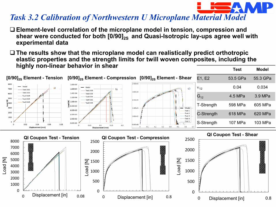
Task 3.2 Calibration of Northwestern U Microplane Material Model Element-level correlation of the microplane model in tension, compression and
shear were conducted for both [0/90]2S and Quasi-Isotropic lay-ups agree well with experimental data
The results show that the microplane model can realistically predict orthotropic elastic properties and the strength limits for twill woven composites, including the highly non-linear behavior in shear
010002000300040005000600070008000
0 0.02 0.04 0.06 0.08
QI Coupon Test - Tension
Load
[N]
Displacement [in]0
500
1000
1500
2000
2500
0 0.2 0.4 0.6 0.8Displacement [in]
QI Coupon Test - Compression
0
500
1000
1500
2000
2500
0 0.2 0.4 0.6 0.8
Load
[N]
Displacement [in]
QI Coupon Test - Shear
Load
[N]
[0/90]2S Element - Shear[0/90]2S Element - Compression[0/90]2S Element - Tension
Test Model
E1, E2 53.5 GPa 55.3 GPa
ν12 0.04 0.034
G12 4.5 MPa 3.9 MPa
T-Strength 598 MPa 605 MPa
C-Strength 618 MPa 620 MPa
S-Strength 107 MPa 103 MPa
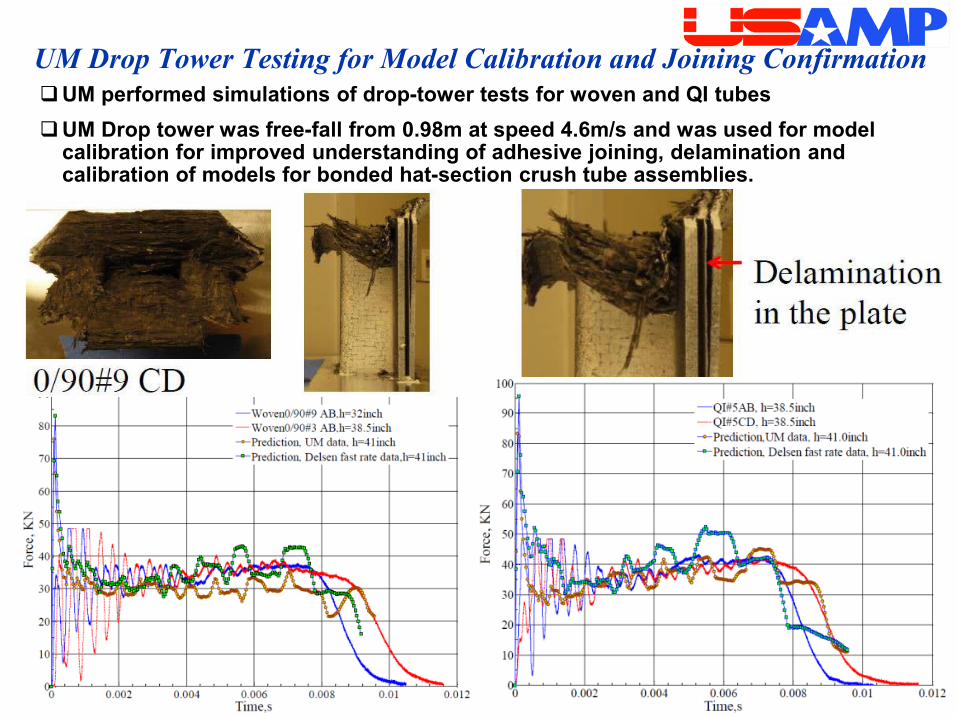
UM Drop Tower Testing for Model Calibration and Joining ConfirmationUM performed simulations of drop-tower tests for woven and QI tubesUM Drop tower was free-fall from 0.98m at speed 4.6m/s and was used for model
calibration for improved understanding of adhesive joining, delamination and calibration of models for bonded hat-section crush tube assemblies.
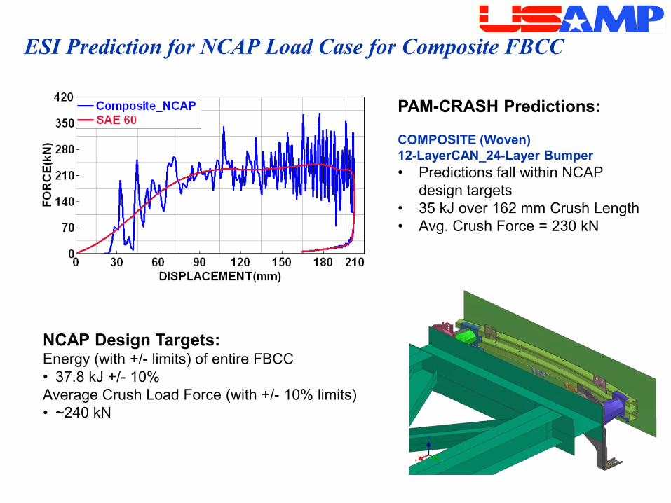
ESI Prediction for NCAP Load Case for Composite FBCC
NCAP Design Targets:Energy (with +/- limits) of entire FBCC• 37.8 kJ +/- 10%Average Crush Load Force (with +/- 10% limits) • ~240 kN
PAM-CRASH Predictions:
COMPOSITE (Woven)12-LayerCAN_24-Layer Bumper• Predictions fall within NCAP
design targets • 35 kJ over 162 mm Crush Length• Avg. Crush Force = 230 kN

Manufacturable Design of the Carbon Composite FBCC Ready FY2015
The Beam is a carbon fabric/epoxy prepreg, 24-ply QI C-channel, 5.6mm thick, with carbon SMC ribs, molded in one piece.
The Crush Cans are carbon fabric/epoxy prepreg, 12-ply QI, 2.8mm thick, with carbon SMC flanges at the front and the back.
The crush cans are bonded on the side flanges, with rivets to act as peel stoppers. The cans are bonded into SMC pockets in the beam.
Final design of the FBCC used PAM-CRASH for CAE, estimates 40% mass savings over steel.
ESI has implemented the UM’s meso-scale RUC material model in PAM-CRASH, and will release it in FY2016 for broader evaluation by industry.
Patent application filed in November 2015
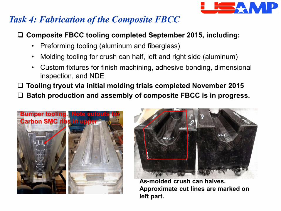
Task 4: Fabrication of the Composite FBCC Composite FBCC tooling completed September 2015, including:
• Preforming tooling (aluminum and fiberglass)• Molding tooling for crush can half, left and right side (aluminum)• Custom fixtures for finish machining, adhesive bonding, dimensional
inspection, and NDE Tooling tryout via initial molding trials completed November 2015 Batch production and assembly of composite FBCC is in progress.
Bumper tooling. Note cutouts for Carbon SMC ribs in upper
As-molded crush can halves. Approximate cut lines are marked on left part.
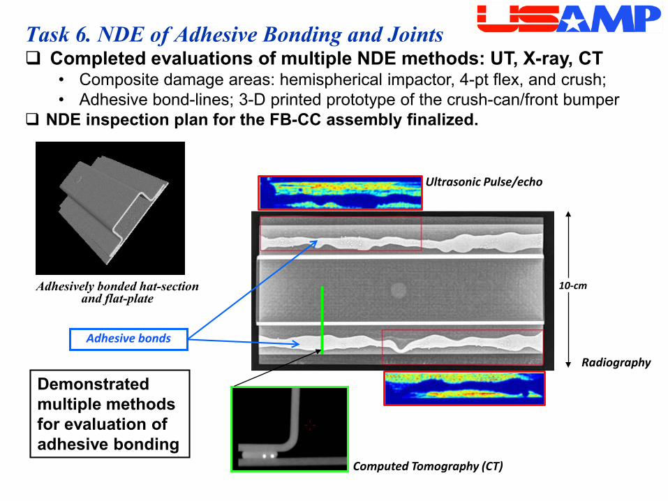
Task 6. NDE of Adhesive Bonding and Joints
Ultrasonic Pulse/echo
Radiography
10-cmAdhesively bonded hat-section and flat-plate
Computed Tomography (CT)
Adhesive bonds
Demonstrated multiple methods for evaluation of adhesive bonding
Completed evaluations of multiple NDE methods: UT, X-ray, CT• Composite damage areas: hemispherical impactor, 4-pt flex, and crush; • Adhesive bond-lines; 3-D printed prototype of the crush-can/front bumper
NDE inspection plan for the FB-CC assembly finalized.

Responses to Previous Year Reviewers’ Comments (Refer to 2015 AMR Comments, page 41-43)We appreciated the overall positive feedback last year. A few comments can be addressed.Question 1: A reviewer asked about Approach. The VMM flow chart shows the progression of increasingly complex modeling steps (coupon tests thru single element, hat and FBCC tests) that integrate the VMM project’s comprehensive material characterization outcomes to generate the needed parameters and material cards for CAE using 4 commercial and 2 academic models.Question 2: A reviewer asked about Characterization Techniques. The extensive list of material property tests and size-effect tests performed on candidate thermoset composite materials is also listed in the flow chart, and will help to identify the gaps in modeling and performance of existing commercial codes at each stage of validation.
Question 4. A reviewer asked about Non-destructive testing during future research.Non-destructive testing is being used throughout each stage of the VMM project to ensure material quality and to assess damage after mechanical and crash testing.

Collaboration and Coordination with Other InstitutionsNorthwestern University Sub-recipient. Collaboration is within the VT program. Northwestern is one of the key members of our team. Prof. Bazant has worked
with ACC on the Micro-plane RUC model. He and his team have predictively modeled the crush cans for this project, to determine if their material model can be validated in an automotive crash scenario.
University of Michigan Sub-recipient. Collaboration is within the VT program U of M is one of the key members of our team. Prof. Waas has worked with
ACC on the Meso-Scale RUC model. He and his team have predictively modeled the crush cans and bumper beam for this project, to determine if their model can be validated in an automotive crash scenario.
Wayne State University Sub-recipient. Collaboration is within the VT program Wayne State is providing the crash testing for the project, including high speed
sled tests and lower speed pendulum tests. Prof. Newaz and his team are participating with instrumentation, equipment, protocols, testing, and crash analysis. (In progress)

Collaboration with other institutions (continued)M-Tech International, LLC Vendor. Collaboration is within the VT program. M-Tech has taken over from NCMS in August 2015 as the Technical Project
Manager for the remainder of the VMM project. (In progress)
ESI Vendor. Collaboration is within the VT program. ESI is the prime vendor for application of commercial modeling codes. They are
responsible for the predictive analysis of the steel FBCC and the design and predictive analysis of the composite FBCC using four different codes. (In progress).
Continental Structural Plastics Vendor. Collaboration is within the VT program. CSP is the major composite fabrication supplier, responsible for fabrication of
plaques and simple shapes for materials evaluation, as well as the fabrication and assembly of the composite FBCC (In progress).
Highwood Technology LLC Vendor. Collaboration is within the VT program. Highwood Technologies is responsible for the development of NDE for the carbon
fiber composites. (In progress).

Dow Automotive • Vendor. Collaboration is within the VT program.• Dow is responsible for joining and final assembly of the composite FBCC (In
progress).
Shape Corp• Vendor. Collaboration is within the VT program.• Shape is leading the evaluation of Thermoplastic materials for FBCCs.
Livermore Software Technology Corp• Vendor. Collaboration is within the VT program.• LSTC is calibrating LS-DYNA models with VMM material data to deliver custom
material cards for CAE of the FBCC. (In progress).
Altair Engineering• Vendor. Collaboration is within the VT program.• Altair is calibrating RADIOSS models with VMM material data to deliver custom
material cards for CAE of the FBCC. (In progress).AlphaSTAR Corp.
• Vendor. Collaboration is within the VT program.• AlphaSTAR is calibrating GENOA-based multi-scale models with VMM material
data to deliver custom material cards for CAE of the FBCC. (In progress)
Collaboration with other institutions (continued)

Proposed Future Work
FY 2016 Complete composite FBCC crash testing. Analyze data and compare to the predictions from commercial and
academic codes. Investigate opportunities for thermoplastic materials to improve design
efficiency. Demonstrate NDE methodologies for FBCCs. Propose methods for Structural Health Monitoring (SHM) of the
composite FBCC.FY 2017 Complete final report and closeout.Final report will include remaining challenges/barriers, and provide a gap analysis on the model(s) shortcomings that identifies specifically what aspects of the model contributes to lack of agreement with data.
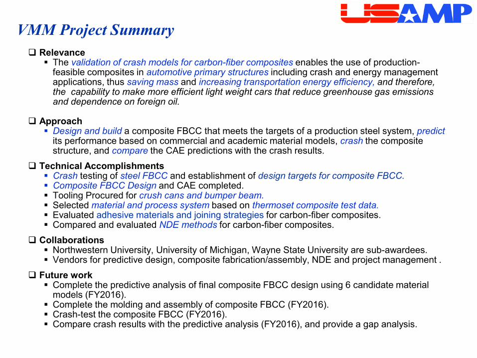
VMM Project Summary Relevance The validation of crash models for carbon-fiber composites enables the use of production-
feasible composites in automotive primary structures including crash and energy management applications, thus saving mass and increasing transportation energy efficiency, and therefore, the capability to make more efficient light weight cars that reduce greenhouse gas emissions and dependence on foreign oil.
Approach Design and build a composite FBCC that meets the targets of a production steel system, predict
its performance based on commercial and academic material models, crash the composite structure, and compare the CAE predictions with the crash results.
Technical Accomplishments Crash testing of steel FBCC and establishment of design targets for composite FBCC. Composite FBCC Design and CAE completed. Tooling Procured for crush cans and bumper beam. Selected material and process system based on thermoset composite test data. Evaluated adhesive materials and joining strategies for carbon-fiber composites. Compared and evaluated NDE methods for carbon-fiber composites.
Collaborations Northwestern University, University of Michigan, Wayne State University are sub-awardees. Vendors for predictive design, composite fabrication/assembly, NDE and project management .
Future work Complete the predictive analysis of final composite FBCC design using 6 candidate material
models (FY2016). Complete the molding and assembly of composite FBCC (FY2016). Crash-test the composite FBCC (FY2016). Compare crash results with the predictive analysis (FY2016), and provide a gap analysis.

Backup Slides
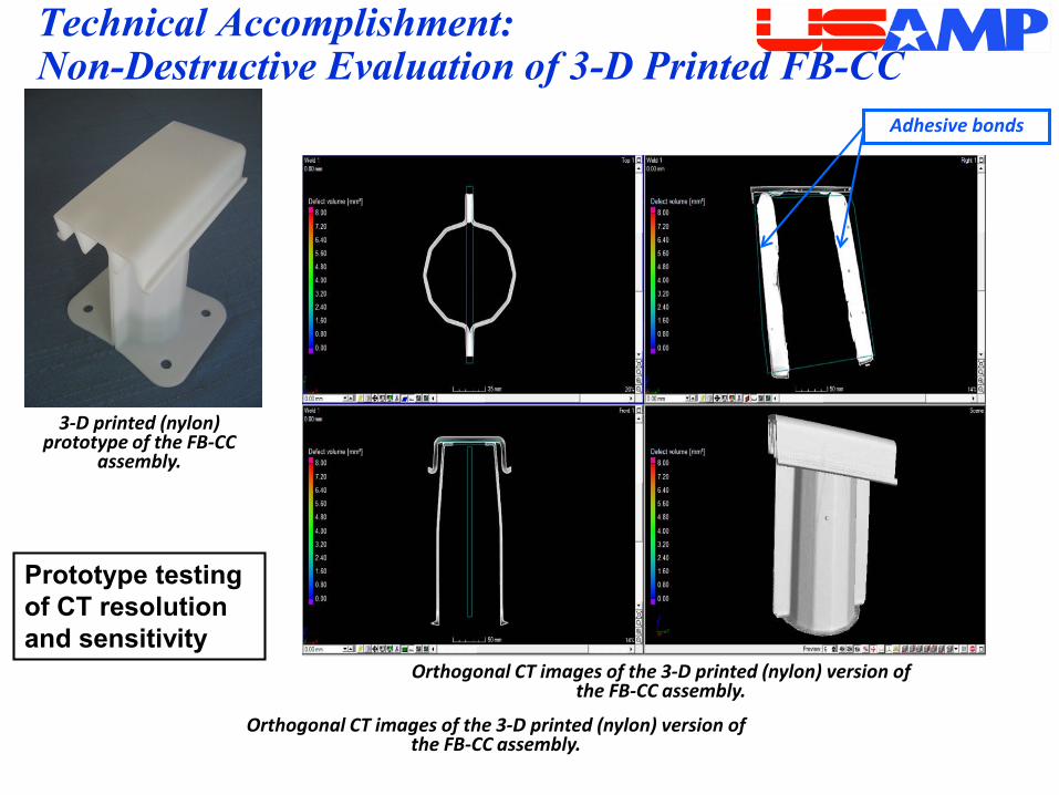
Orthogonal CT images of the 3-D printed (nylon) version of the FB-CC assembly.
Technical Accomplishment:Non-Destructive Evaluation of 3-D Printed FB-CC Section Adhesive bonds
3-D printed (nylon) prototype of the FB-CC
assembly.
Orthogonal CT images of the 3-D printed (nylon) version of the FB-CC assembly.
Prototype testing of CT resolution and sensitivity

Task 6: Non-Destructive Evaluation (NDE) of Composite FBCCs
Milestone 15: Methodology for NDE of FBCC Composite Structures and Joints
Milestone 16: NDE of FBCC Composite Structures and Joints
Milestone 17: Structural Health Monitoring (SHM) Feasibility Analysis
•Validate NDE capabilities•Detect fabrication discrepancies•Image impact damage•Calibrate defect size to strength loss
•Detect damaging impacts•Wireless sensors
crush can
crush can
Front bumper
•Verify fabrication quality•Detect impact with SHM sensors•Assess damage areas
System 2. Optical fiber Bragg grating: 8–mm strain sensors
2-3 mm
System 1. MEMS accelerometer with vibro power, RFD readout