Embed Size (px)
Citation preview

1
VALIDATION OF MATERIAL MODELS: FABRICATION AND CRUSHTESTING OF CARBON FIBER REINFORCED THERMOPLASTICCOMPOSITES FOR AUTOMOTIVE ENERGY ABSORPTIONAPPLICATIONS
Jeff McHenry, Shape Corporation
Jian Tao, FCA US LLC
Anthony Coppola, General Motors
Glen Smith, Ford Motor Company
Manish Mehta, M-Tech International LLC
AbstractThermoplastic composites are increasinglycompeting with thermosets for structuralapplications in the automotive industry becauseof advantages such as shorter cycle time,excellent toughness, and better recyclability.However, thermoplastic composites, especiallythose that are reinforced with continuouscarbon fibers, still have significant barriers toovercome before they are widely used in largeand complex automotive structural components.These include cost, development of massproduction methods, and predictive tools andtechniques for performance and processing.
Research was conducted as part of theValidation of Crash Material Models (VMM) forAutomotive Carbon-Fiber Composite Structuresvia Physical and Crash Testing project [1]. This isa $7 million U.S. DOE and USAMP CooperativeAgreement project to validate and assess theability of physics-based material models topredict crash performance of primary load-carrying carbon fiber composite automotivestructures. In this portion of the project, weexplored the use of continuous carbon fiberreinforced nylon for crush cans in a vehicle front-
end energy absorption structure. We alsoinvestigated methods to use low cost carbonfiber developed by Oak Ridge National Lab’sCarbon Fiber Technology Facility (CFTC) in thesestructures. This paper will review the design,fabrication, and testing of these materials.
Background of ProjectPurposeRecently, the need for lightweight materials inautomobiles has surged to meet the demand forincreased fuel economy. In response, compositematerials are moving from a material for high-end applications to viability in large-scaleproduction vehicles. Part of this change is theincreased monetary value placed onlightweighting when making material decisions.However, new materials and manufacturingprocesses are being developed in tandem tobring down the cost of composites and makethem more competitive.
The goal of the VMM project was to assess theability of material models to predict the crashbehavior of a structural composite system duringcrash. To accomplish this, a front bumper andcrush can (FBCC) assembly was chosen forsimulation and testing of carbon fibercomposites. While simulation was the mainfocus, one critical task was to manufacture theFBCCs and supply them to the crash team forevaluation. Materials and processes wereselected to be relevant to both current andanticipated future technologies that areavailable to the industry.

2
Design of Crush StructuresThe composite FBCC design was based on theexisting packaging space and performance of aproduction from steel system [2]. The FBCC iscomprised of five parts, including the beam andthe right- and left- hand side crush cans, whichare each composed of one “A” and one “B” half(Figure 1). The crush cans are designed as twohalves of a tapered cylinder that are joined usingflanges. The components of the FBCC are joinedusing adhesive bonding. In addition, rivets arestrategically placed on the crush can flanges toenhance bonding and mainly act as peelsstoppers. Features were designed into the beamand crush cans to facilitate the bonding process.A system of bumps and dimples along the crushcan flanges that were molded in is to align thehalves and control the bond gap (Figure 2). TheFBCC is mounted to the vehicle using four boltholes in the large flanges on the vehicle side ofthe crush cans. In the event of a frontal crash, thecrush cans are the main energy absorbers and doso by progressive crush of the composite. Bydesign, crush starts at the impacted-end of thecrush can and progresses towards the vehicle-end. While traditional metal bumper systemsabsorb energy through many deformation,composites absorb through delamination,micro-cracks, fiber fractures, and other damagesthat are generated during a dynamic loadingevent.
Figure 1: CAD image of the composite FBCC system.
a)
b)
c)
Figure 2: Details of the bonded interface for the crushcan halves. a) Zoom-in of half “A” showing the bumpsand rivet holes. b) Zoom-in of half “B” showing thereceiving dimples and matching rivet holes. c)Schematic of the assembled crush can showing thelocation of the interface. Rivets are not shown.
Thermoplastic BackgroundCurrently, there is much discussion regarding theuse of thermoset vs. thermoplastic materials fora variety of applications in the automobile.Thermosets are generally thought to be easier toprocess and result in higher strength materials,while thermoplastic materials have much higherfracture toughness and better recyclability,among many other differences. Improvementsin thermoplastic material technology and theirpotential energy absorption in crush, makesthem attractive in an FBCC system. In thisproject, we investigated both thermoset andthermoplastic materials in the crush cans andcompared them head-to-head.
Material cost is a key driver in making compositematerials competitive. Recently, new low costcarbon fibers (LCCF) developed by ORNL’s CFTF

3
have become available for evaluation, and soonon the commercial market. These fibers areadvertised as having mechanical performancecomparable with commercially availablestandard modulus carbon fibers, at a potentialcost of just $5.5/lb. This cost is significantlybelow the current market cost of over $8/lb. forsimilar fibers. Towards our goal of validating themodels using the most up-to-date materials, weincorporated these carbon fibers in the crush canfor our evaluation.
Material SelectionMaterials and Process Selection andDevelopmentThe main objective of this portion of the projectwas to demonstrate predictability during a crashevent when using a thermoplastic compositeversion of the crush can. Tooling was developedalong with a layup and flat pattern for thethermoset epoxy prepreg and polyester basedSMC materials. By using a similar strategy for thethermoplastic material, the team sought todirectly compare energy absorption of carbon-fiber/ thermoplastic composites to carbon-fiber/thermoset composites. This required partsto be molded using 2x2 twill woven carbon fabricin the can body layered in a quasi-isotropicconfiguration. Additionally a chopped carbonfiber thermoplastic was needed to fill in theflange areas of the part.
Material Offerings and AvailabilityMaterial requirements and part design limitedthe supply base immediately. After pursuing theremaining material suppliers, commercialavailability and engineering support determinedthe materials offered by Tencate PerformanceComposites and BASF would meet the need ofthe project. Additionally, Nylon 6 was thechosen thermoplastic resin system based oncompatibility with carbon fiber, low processingtemperature, and availability among the otheroptions.
The material supplied by Tencate was 200 gsm2x2 twill woven carbon fabric laminated withlayers of PA6 film. This material was based on astandard product, however, due to theperformance and molding requirement, thelaminate panels were further tailored for thisproject. This material was used in the crush canbody to serve as an equivalent to the epoxyprepreg system used previously.
Carbon fiber tape pre-impregnated with PA6supplied by BASF was used to make the flangesof the crush can. This was a standard productthat allows significant flexibility in processing. Itwas selected to mimic the characteristic of theSMC used previously in the thermoset system.Additionally, it would serve to provide someprocess friendly characteristics needed forhandling the charge during molding.
Layup Selection and Panel ProductionThe crush can design and simulation suggested aquasi-isotropic layup would produce a crushmode that was more stable and efficient than across-ply 0/90 layup [2,3]. Target laminatethickness was 2.81 mm in the can body and 5.81mm in the back flange. Panel production wascompleted using a vertical stack press forlamination (Tencate Performance Compositesdivision). Carbon fabric was alternated with PA6film to achieve desired thickness and fiberwetting. Heat was cycled to 535° F and cooledto 200° F under 100 psi of pressure to produce95 cm X 125 cm panels. Although the thermosetmanufacturing used a 12 layer laminate, thethermoplastic film thickness and viscosity limitedconsolidation to 7 layers of carbonreinforcement. Any additional layers wouldexceed the design thickness, preventing directcomparison of crash performance to models andthermoset parts construction. The final panelconstruction was 0/±45/90/±45/90/±45/0. Thisachieved a panel thickness of 2.85 mm.

4
Processing DevelopmentCrush Can Half Production ProcedureThe manufacturing of the PA6/carbon crush canrequired a different set of processing conditionsto allow use of the compression tooling. Thesecomposite charges required a design for fasttransfer into the mold to keep the PA6 resin at amolten state until mold close. These compositecharges also required an oven that would allowfor steady rise to melt temperature withoutreaching a temperature gradient that wouldcause the resin oxidation and further degradethe performance. To produce can halves fromthe laminated composite panels the followingprocedure was followed:
1. Fibersim pattern/charge laser cut fromlaminated panel for the crush can body;
2. UD carbon tape molded to proper chargedimensions for the crush can flanges;
3. Charges heated in oven;
4. Charges rapidly transferred from oven tomold;
5. Mold closes to form and cool part;
This process, described in detail below, was usedto produce the charges that were trimmed andjoined to produce crush can halves.
Draping Analysis for Preform DesignFibersim was used initially to evaluate thepreforming process for a single ply of material.Initial simulation of the preforming process forthe crush can half used a simple rectangular plydesign. This rectangular design was unable toconform to the complex geometry of the crushcan half without significant wrinkling,particularly around the edges of the ply. Figure3 shows a modified ply shape that wasdeveloped. Simulation results confirmed thatthis improved design was better able to conformto the geometry during preforming withoutwrinkles. Draping analysis was found to be a
valuable tool to workout potential preformingissues before finalizing the tool and ply-shapedesigns.
Figure 3: Based on the Fibersim predictions showingwrinkling when the kit was rectangular, a modified plydesign was developed. a) The flat pattern generatedby Fibersim used for thermoset kit and thermoplasticpattern. b) The forming simulation for Fibersim flatpattern.
Charge Pattern CuttingThe pattern used for the laminated twill wovencarbon panel was the same as used to producethe thermoset preforms. Since, thereinforcement material and layup were similar,the draping behavior was also very similar. Theflat pattern shown is Figure 3a was nested withinthe laminated panel to produce 9 pieces persheet. Although waterjet trimming is preferred,a laser was used to cut these patterns due toavailability. The resulting cut showed a heataffected zone of approximately 3 mm; however,much of this material is trimmed off duringmolding.
Flange Preform ProductionThe process flow for producing the choppedcarbon fiber charges for the flanges is shown inFigure 4. The material chosen to fill the flangesof the crush can was UD carbon tape. Thismaterial, when chopped into platelets, iscapable of flowing, yet has some challengeswhen handling and transferring during molding.The heated charge would need a carrier toprevent the chopped material from separatingduring transfer. This carrier was created bylaminating the UD tape into 1.2 mm thick 0/90panels which were cut to the net shape of each

5
flange. These laminated UD layers serve as abase to the chopped material for easiertransport. Each flange needed a measuredamount of material to fill the entire thicknessand pressurize the cavity without preventing thecan body material from reconsolidating.Combining a calculated mass into a near netshape charge ensured critical areas of the partwere filled during compression. This net shapewas produced using a steel or die that was filledfirst with the UD laminate, and second with themeasured mass of chopped material. Thisarrangement was heated to melt temperature ina radiant oven to tack all the material together.Once the material was cooled, it was removedfrom the die and set aside for molding. Duringthe compression molding, these charges werereheated to melt state to fill in the flanges of thecrush can.
Figure 4: Flange preform productions steps
Compression MoldingThe success of the molding of the crush canhalves relied heavily on the composite chargedesign, placement accuracy, and rate oftransporting the charges from oven to closedmold. Initial trials identified the proper toolorientation shown in Figure 5. Placementsequence required chopped material to beinserted prior to the can body charge. Manual
transfer and manipulation of the moltencharges, while not without error, allowedenough of the preform to clear the shear edgesbefore shutoff to completely consolidate theparts. Transfer time ranged from 18-22 secondsfrom the point of removal of the charges to startof mold close. The aluminum tooling was heatedto 150°C by steam to prevent rapid heat removalfrom the composite prior to compression. Oncethe targeted closed mold pressure was reached,the tool was held closed for 60 seconds to coolthe completed part to a state of dimensionalstability. This part and tool design did notrequire high ejection force to remove, so ademold temperature of 150°C was not aconcern. Once outside the compression moldthe part was cooled in open air at a nearby workstation. Total cycle time from removal ofcharges from oven to removal of completed partfrom the tool was approximately 2 minutes.Once cooled, the parts were measured andshipped for trimming and joining. In total, 18complete crush can sets were molded. Final partthickness averaged approximately 2.81 mm inthe can body and 5.27 mm in the base flange.
6
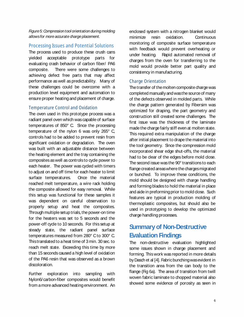
Figure 5: Compression tool orientation during moldingallows for more accurate charge placement.
Processing Issues and Potential SolutionsThe process used to produce these crush cansyielded acceptable prototype parts forevaluating crash behavior of carbon fiber/ PA6composite. There were some challenges toachieving defect free parts that may affectperformance as well as predictability. Many ofthese challenges could be overcome with aproduction level equipment and automation toensure proper heating and placement of charge.
Temperature Control and OxidationThe oven used in this prototype process was aradiant panel oven which was capable of surfacetemperatures of 850° C. Since the processingtemperature of the nylon 6 was only 265° C,controls had to be added to prevent resin fromsignificant oxidation or degradation. The ovenwas built with an adjustable distance betweenthe heating element and the tray containing thecomposites as well as controls to cycle power toeach heater. The power was cycled with timersto adjust on and off time for each heater to limitsurface temperatures. Once the materialreached melt temperature, a wire rack holdingthe composite allowed for easy removal. Whilethis setup was functional for these samples itwas dependent on careful observation toproperly setup and heat the composites.Through multiple setup trials, the power-on timefor the heaters was set to 5 seconds and thepower-off cycle to 10 seconds. For this setup atsteady state, the radiant panel surfacetemperatures measured from 280° C to 300° C.This translated to a heat time of 3 min. 30 sec. toreach melt state. Exceeding this time by morethan 15 seconds caused a high level of oxidationof the PA6 resin that was observed as a browndiscoloration.
Further exploration into sampling withNylon6/carbon-fiber composites would benefitfrom a more advanced heating environment. An
enclosed system with a nitrogen blanket wouldminimize resin oxidation. Continuousmonitoring of composite surface temperaturewith feedback would prevent overheating orunder heating. Rapid automated removal ofcharges from the oven for transferring to themold would provide better part quality andconsistency in manufacturing.
Charge OrientationThe transfer of the molten composite charge wascompleted manually and was the source of manyof the defects observed in molded parts. Whilethe charge pattern generated by Fibersim wasoptimized for draping, the part geometry andconstruction still created some challenges. Thefirst issue was the thickness of the laminatemade the charge fairly stiff even at molten state.This required extra manipulation of the chargeafter initial placement to drape the material intothe tool geometry. Since the compression moldincorporated shear edge shut-offs, the materialhad to be clear of the edges before mold close.The second issue was the 90° transitions to eachflange created areas where the charges migratedor bunched. To improve these conditions, themold should be designed with charge handlingand forming blades to hold the material in placeand aide in preforming prior to mold close. Suchfeatures are typical in production molding ofthermoplastic composites, but should also beused in prototyping to develop the optimizedcharge handling processes.
Summary of Non-DestructiveEvaluation FindingsThe non-destructive evaluation highlightedsome issues shown in charge placement andforming. This work was reported in more detailsby Dasch et al [4]. Fabric bunching was evident inthe transition area from the can body to theflange (Fig 6a). The area of transition from twillwoven fabric laminate to chopped material alsoshowed some evidence of porosity as seen in

7
Figure 6c. An additional unique characteristic ofthe thermoplastic laminate was the variations infiber density. Distinct bands of resin rich areaswere visible along the surface and toward thecenter of the laminate (Figure 6b, d). Much ofthis could be attributed to the thickness of thelaminate and the heating method used formolding. With this heat source coming fromradiant transfer, it was difficult to ensure acomplete and equal temperature distribution ofthe laminate prior to transfer and compression.
a)
b) C)
d)
Figure 6 a) Radiograph of completed PA6/Carboncrush can showing fiber bunching at base of can body.b) CT scan of crush can body showing resin rich bandswithin laminate. c) CT scan showing some porosity attransition to flange. d) Ultrasonic inspection showingunequal fiber density though thickness of twilllaminate.
Material TestingCoupon Testing and SimulationTwo materials as indicated in the section ofMaterial Selection were used to generateMAT_058 for LS_DYNA simulation. This testingconsisted of tension, compression, and shear at0°, 45°, 90° at strain rates of 0.01/s, 1.0/s, 100/s.This material card was generated to replace thethermoset material card for crash simulation butwas not initially tuned using an intermediatecrush structure due to time constraints of thisportion of the project. This data was collectedafter project extension for use in futureoptimization of simulation and part design. Thisinitial simulations done without this data isshown in Figure 7 with an overlay of an axialimpact of a single crush can at 5.14 m/s.
Figure 7: Overlay of axial crush can impact with aMAT_058 card generated without tuning.

8
AssemblyCrush Can TrimmingFollowing molding, the crush can halves weretrimmed to final dimensions using CNC milling.Custom fixtures were designed to accuratelyhold the complex parts in place during trimming.After that, the holes were drilled through theside flanges for rivets used as part of the joiningprocess.
Adhesive SelectionCoupon level testing on the adhesive wasconducted to compare several options. Threeadhesives were evaluated for use in joining thethermoset FBCC system, each with distinctmechanical properties. Only two of thoseadhesives were compatible and tested forbonding the PA6/Carbon components:
· DOW BETAMATE® 73326/73327, a 2-component epoxy adhesive, with lap shearof approximately 10 MPa and elongation ofapproximately 13%
· DOW BETAFORCE® 2850L, a 2-componentpolyurethane (PU) adhesive, with lap shearfor metal substrates of less than 11 MPaand elongation of approximately 115%
Table 1: Result Comparison of bond strengths on thePA6/Carbon System
Component JoiningThe parts were joined using adhesive bondingand riveting. The mating surfaces were primedwith Dow BETAPRIME 5406 and BETASEAL 43532then bonded with BETAFORCE 2850L. Rivets andmechanical clamping fixture held the parts inplace during cure.
While this procedure did successfully achievegeometrically-accurate and repeatable joining ofthe components, it is carried from the thermosetjoining operations due to time constraints asmentioned above. There are multipletechnologies for joining the thermoplasticcomponents through the welding process suchas hot plate, ultrasonic, IR, laser etc. that fullyleverages the resin benefits.
Physical TestingSled Testing ResultsSled tests were performed on both thethermoset- and thermoplastic-based (standardCF only, not LCCF) crush cans to compare theirbehavior. While the materials used for thethermoset and thermoplastic crush cans werenot perfect analogs, they were designed to be assimilar as available materials allowed. Acomparison of the materials is shown in Table 2.Figure 11 shows an image of a crush can readyfor testing.
Crash results showed very similar behaviorbetween the thermoset and thermoplastic crushcans (Figure 12). Thermoplastic crush cans hadslightly less total crush length and slightly higherpeak load than the thermoset crush cans.However, it is notable that the thermoplasticcrush cans contained 38% carbon fiber byvolume, whereas the thermoset crush canscontained 58% carbon fiber by volume While adetailed cost analysis has not been conducted onthe two materials, this has the potential toreduce the cost of thermoplastic-based materialcompared to the thermoset-based material.Another notable difference between the
9
behaviors of the two materials is that thethermoplastic material fractures into largerpieces and creates less dust. Post-test images ofthe crush cans show this difference very clearly(Figure 13).
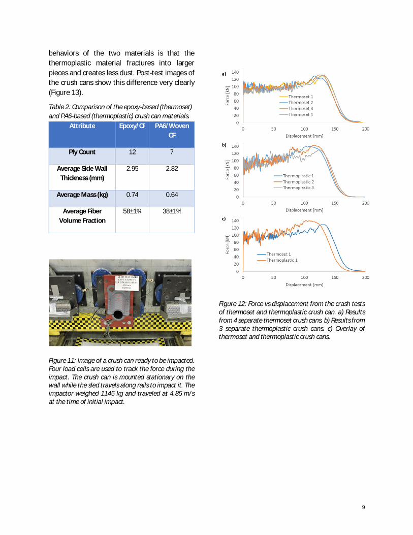
Table 2: Comparison of the epoxy-based (thermoset)and PA6-based (thermoplastic) crush can materials.
Figure 11: Image of a crush can ready to be impacted.Four load cells are used to track the force during theimpact. The crush can is mounted stationary on thewall while the sled travels along rails to impact it. Theimpactor weighed 1145 kg and traveled at 4.85 m/sat the time of initial impact.
Figure 12: Force vs displacement from the crash testsof thermoset and thermoplastic crush can. a) Resultsfrom 4 separate thermoset crush cans. b) Results from3 separate thermoplastic crush cans. c) Overlay ofthermoset and thermoplastic crush cans.
Attribute Epoxy/CF PA6/WovenCF
Ply Count 12 7
Average Side WallThickness (mm)
2.95 2.82
Average Mass (kg) 0.74 0.64
Average FiberVolume Fraction
58±1% 38±1%
10
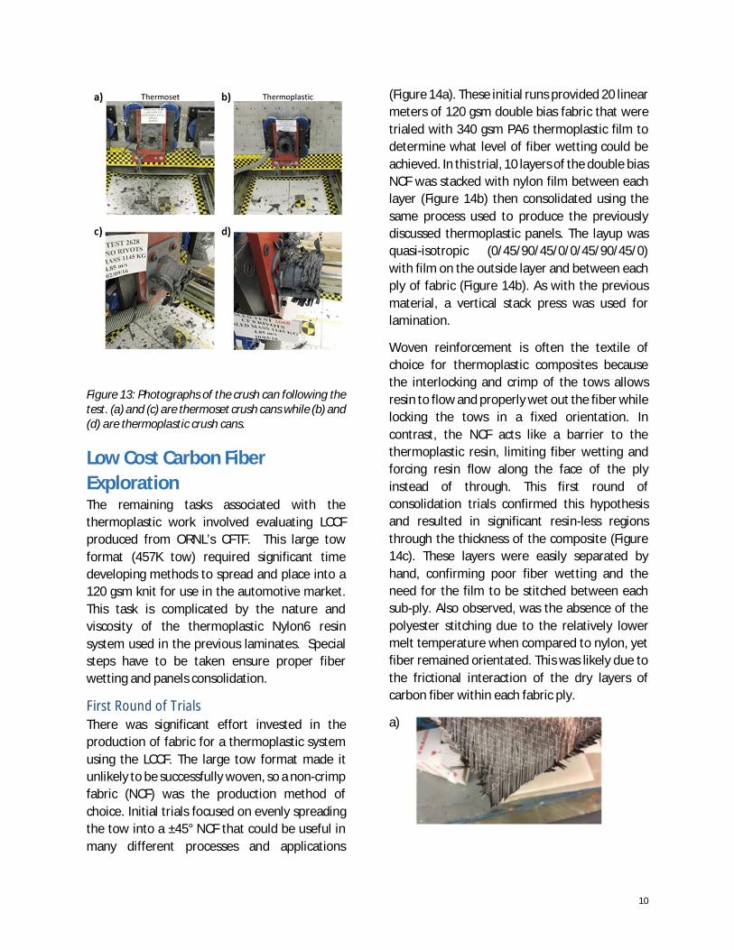
Figure 13: Photographs of the crush can following thetest. (a) and (c) are thermoset crush cans while (b) and(d) are thermoplastic crush cans.
Low Cost Carbon FiberExplorationThe remaining tasks associated with thethermoplastic work involved evaluating LCCFproduced from ORNL’s CFTF. This large towformat (457K tow) required significant timedeveloping methods to spread and place into a120 gsm knit for use in the automotive market.This task is complicated by the nature andviscosity of the thermoplastic Nylon6 resinsystem used in the previous laminates. Specialsteps have to be taken ensure proper fiberwetting and panels consolidation.
First Round of TrialsThere was significant effort invested in theproduction of fabric for a thermoplastic systemusing the LCCF. The large tow format made itunlikely to be successfully woven, so a non-crimpfabric (NCF) was the production method ofchoice. Initial trials focused on evenly spreadingthe tow into a ±45° NCF that could be useful inmany different processes and applications
(Figure 14a). These initial runs provided 20 linearmeters of 120 gsm double bias fabric that weretrialed with 340 gsm PA6 thermoplastic film todetermine what level of fiber wetting could beachieved. In this trial, 10 layers of the double biasNCF was stacked with nylon film between eachlayer (Figure 14b) then consolidated using thesame process used to produce the previouslydiscussed thermoplastic panels. The layup wasquasi-isotropic (0/45/90/45/0/0/45/90/45/0)with film on the outside layer and between eachply of fabric (Figure 14b). As with the previousmaterial, a vertical stack press was used forlamination.
Woven reinforcement is often the textile ofchoice for thermoplastic composites becausethe interlocking and crimp of the tows allowsresin to flow and properly wet out the fiber whilelocking the tows in a fixed orientation. Incontrast, the NCF acts like a barrier to thethermoplastic resin, limiting fiber wetting andforcing resin flow along the face of the plyinstead of through. This first round ofconsolidation trials confirmed this hypothesisand resulted in significant resin-less regionsthrough the thickness of the composite (Figure14c). These layers were easily separated byhand, confirming poor fiber wetting and theneed for the film to be stitched between eachsub-ply. Also observed, was the absence of thepolyester stitching due to the relatively lowermelt temperature when compared to nylon, yetfiber remained orientated. This was likely due tothe frictional interaction of the dry layers ofcarbon fiber within each fabric ply.
a)

11
b)
c)
Figure 14: a) Double bias produced from initial trialswith large tow low cost carbon fiber. b) Schematicshowing the stacking arrangement of the nylon andNCF in the first trial. c) Section of first low cost carbonpanels showing visible bands of resin and dry fiber.
Second Round of TrialsThe primary concern with the original trials wasthat the high viscosity thermoplastic film wouldnot penetrate past the carbon fibers to reach thearea between the +45° and -45° plies. To addressthis, the team modified the fabric productionprocess to stitch a layer of nylon film betweenthe +45° and -45° sub-plies. To prove the conceptwas possible with the fabric productionequipment, PA6 film was initially stitched to theoutside of the fabric (Figure 15a). After thesepromising results, the final step of stitching filmin between each sub-ply was successfullycompleted producing 20 linear meters ofmaterial (Figure 15b). The resulting material was120 gsm carbon combined with 340 gsm film toproduce a 460 gsm thermoplastic fabric kit. Thisfabric was then sent to be laminated withmultiple layers of alternating film and fabriccontaining film to achieve the target thicknessand quasi-isotropic layup (Figure 15c).
The material produced with PA6 film stitchedbetween each sub-ply was laminated into 8 layerpanels (0/45/90/45/45/90/45/0) with filmadded between each layer of fabric. This
resulted in a laminate with PA6 film betweeneach sub-ply (Figure 15c). Fiber wetting wasimproved, but fiber and resin migration was asignificant problem (Figure 15d). The defectoccurred due to the melt temperature of thepolyester stitching being well below the melttemperature of the Nylon 6 resin. This is evidentvisually in Figure 16d, as no evidence of thestitching can be seen. The result is a laminatewith a high variation in fiber orientation anddensity. This is an area that would requirefurther development to provide stitchingmaterial that would survive the thermoplasticprocessing temperatures. Additionally, the fibervolume fraction should be optimized with filmthickness to provide better laminatingcharacteristics.
a) b)
c)
d)
Figure 15: a) Early development of stitching PA6 filmto outside of carbon knit to validate process. b)Sample of final double bias with film stitched betweeneach sub-ply. Some carbon tow has been removed toshow film presence in knit. c) Schematic showing thestacking arrangement of the nylon and NCF in thesecond trial. d) Panel produced with film stitchedbetween each sub-ply showing fiber wash.

12
Comparison of Thermoplastic andThermoset Component PerformanceDrop Tower Testing ResultsDrop tower tests were performed on hat-sections (see Figure 16 for sample details)molded from carbon fiber/epoxy prepreg,woven standard carbon fiber and nylon, andNCF LCCF and nylon material for comparison ofthe materials. Note that the LCCF-basedmaterial described above had major defects tofiber alignment and spacing and results are onlyprovided for general comparison purposes.Significant improvements to the crushperformance would be expected if thesedefects were eliminated. The drop tower testswere performed by GM R&D at the WarrenTechnical center. During the test, a 276 kgweight was dropped from 84 cm. The hatsection samples were supported by placingthem approximately 1 inch into the cavity of analuminum fixture providing approximately 1-3mm of spacing around the edges and using hot-melt adhesive to hold the sample in place (
Figure16). Two bolts were added on eachflange, as shown in
Figure17, to provide additional support betweenthe two parts of the sample.
Drop tower results are shown in Figure 18 foreach of the three sample types. Overall, theepoxy-based samples had the highest peak load,while the woven-CF/nylon-based materialperforms similarly. In contrast, the LCCF/nylonmaterial showed significantly lower loadsthroughout the test, likely as a result of thedefects in the fiber architecture. Additionally,the use of an NCF for this material, rather thanweaving the carbon fiber, may have alsocontributed to these differences. However, theexperiment was not designed with the proper
controls to indicate whether the difference inNCF vs. woven, the defects in the NCF samples,or the effect of reduced fiber performance in theLCCF were a larger contributor to the poorperformance of these samples.
a)
b)
Figure 16: a) Schematic of the geometry of the tubesample. b) Photograph of the sample.
Figure 17: Image of hat section ready for drop towertesting.

13
a)
b)
c)
Figure 18: Drop tower test results for a) carbonfiber/epoxy prepreg, b) woven standard carbon fiberand nylon, and c) NCF LCCF material. Each curverepresents the results from 1 test. Only one test wasrun for the epoxy-based material under theseparticular conditions.
Summary and ConclusionsIn this portion of the VMM project, wedeveloped a manufacturing process and thenproduced thermoplastic composite parts forcrash testing of the crush can for an automotivefront energy absorption system. This includedselection of materials and measurement ofmaterial properties that were then passed ontothe design/CAE team for designing andpredicting performance of the FBCC. Significanteffort was placed in manufacturing athermoplastic carbon composite crush can fordirect comparison to an epoxy carbon system.Manufacturing is a key consideration in thedevelopment of models for predicting compositebehavior in crash events. The realities and
challenges of the molding operation result inimperfect parts containing defects. However,comparison of these two resin systems showedsignificant energy absorption potential forthermoplastics in crush can applications. If lowcost carbon fiber reaches large scale production,the automotive industry has an opportunity tobenefit with more integration of carbon fibercomposites at lower cost. Furthermore,thermoplastic composites, given the appropriateenvironment, could make a positive impact tolightweighting in higher volume applications.
AcknowledgementsThis program is supported by the U.S.Department of Energy under CooperativeAgreement Number DE-EE0005661 awarded tothe United States Automotive MaterialsPartnership. Neither the United StatesGovernment nor any agency thereof, nor any oftheir employees, makes any warranty, express orimplied, or assumes any legal liability orresponsibility for the accuracy, completeness, orusefulness of any information, apparatus,product, or process disclosed, or represents thatits use would not infringe privately owned rights.Reference herein to any specific commercialproduct, process, or service by trade name,trademark, manufacturer, or otherwise does notnecessarily constitute or imply its endorsement,recommendation, or favoring by the UnitedStates Government or any agency thereof. Theviews and opinions of authors expressed hereindo not necessarily state or reflect those of theUnited States Government or any agencythereof.
This is a collaboration involving manyresearchers and organization. The authors wouldlike to extend special thanks to, Art Cawley(Dow), Chris Mikesell (Chomarat), Bob Reynolds(Tencate), and Chris Korson (BASF).

14
References1. Coppola, A.M., L. Berger, D. Board, M.
Jones, J. Truskin, and M. Mehta.“Validation of Material Models forCrash Testing of Carbon FiberComposites: Overview,” SPE ACCE, Sept2016, Novi, MI.
2. Trameçon, A., M. Doroudian, R.Dwarampudi, P. Pasupuleti, L. Berger,O. Faruque, Y. Chen, and J. Truskin,“Validation of Material Models: Designof a Composite Bumper-Beam andAssessment of Current Composite CrashSimulation Capabilities,“ SPE ACCE, Sept2016, Novi, MI.
3. Coppola, A.M., L. Berger, G. Smith, D.Armstrong, and C.J. Dasch, “Validationof Material Models: ThermosetComposite Materials and Processing Fora Composite Bumper-Beam System,”SPE ACCE, Sept. 2016, Novi MI.
4. Dasch, C.J., G.J. Harmon, and M.H.Jones, “Validation of Material Models:Non-destructive Testing Throughout theDevelopment of a Carbon-FiberComposite Automotive Front-Bumper/Crash-Can Structure,” SPEACCE, Sept 2016, Novi, MI.