Embed Size (px)
Citation preview

Validation of Grid-Based Hex Mesheswith Computational Solid Mechanics
Steven J. Owen and Tim R. Shelton
�Sandia National Laboratories, Albuquerque, New Mexico, [email protected]
Abstract. Grid-based methods for generating all-hex meshes show tremen-dous promise in automating and speeding up turnaround for computationalsimulations for solid mechanics. Recognizing some of its inherent weaknesses,there has been hesitancy in accepting this technology as a viable option forcritical FEA. This study attempts to compare meshes generated with tra-ditional manual pave-and-sweep technologies with those generated with anautomatic overlay grid method. We use a simple torsion pin analysis to un-derstand both linear-elastic and non-linear elastic-plastic responses with grid-based meshes. This study demonstrates that in the cases tested, equivalentor superior results were achieved with grid-based meshes when compared topave-and-sweep meshes.
Keywords: grid-based, overlay grid, hexahedral mesh generation, parallelmeshing, solid mechanics, pillowing.
1 Introduction
For computational simulation in solid mechanics, the tri-linear 8-node hexelement has long been favored over its tetrahedron counterparts. In spite ofthe often enormous overhead required to generate an all-hex mesh versusgeneration of a tet mesh of similar geometry, hex meshing remains an impor-tant requirement for many analysts. The ability to automatically generatea quality all-hex mesh for an arbitrary solid model has long been a majorresearch challenge.
Most methods for all-hex meshing can be classified as either geometry-firstor mesh-first approaches. The geometry-first approaches, which may include
� Sandia is a multiprogram laboratory operated by Sandia Corporation, a Lock-heed Martin Company for the United States Department of Energy’s NationalNuclear Security Administration under contract DE-AC04-94AL85000.
J. Sarrate & M. Staten (eds.), Proceedings of the 22nd 39International Meshing Roundtable,DOI: 10.1007/978-3-319-02335-9_3, c© Springer International Publishing Switzerland 2013

40 S.J. Owen and T.R. Shelton
algorithms such as mapping[3], sweeping[17], plastering[2][18], whiskerweaving[20] and medial axis[19], involve developing a mesh using the CADboundary representation as a framework from which to build the nodes andelements of a mesh to fill the geometric domain. Mesh-first approaches, such asoverlay and octree grid-based methods[14][22][8] first construct a space-fillinggrid or mesh of nodes and elements. They then employmethods to locallymod-ify the mesh to capture features of the geometry and topology of the CADmodel.
Where geometry-first methods can successfully be employed, they willusually result in high quality hexahedral elements. Since these methodsare generally sensitive to boundary topology, mesh quality at boundariesis normally high. On the other hand, since mesh-first methods operate onnode locations near the boundary to deform elements to fit a given geom-etry, the element quality near boundaries can often suffer. Current state ofmeshing research and development has not yet yielded a fully automaticgeometry-first approach that will work for general geometries. Instead, man-ual tools[4][6][7][1][21] that provide some automation for decomposing themodel into sweepable or mappable topologies have become the staple of all-hex mesh generation practice. Meshes produced in this manner can be heroicefforts requiring the work of many analysts weeks and months of work toproduce meshes of complex assembly models.
Meanwhile, requirements for rapid design turnaround are not being metby current hex meshing practice. For example, at U.S. national labs wherecritical decisions of national security often hinge on information gained fromcomputational tools, the inability to turn around a high quality hex meshin minutes or hours has increasingly become the bottleneck. In addition,science-based engineering questions requiring vast computational resourcesare increasingly becoming the norm. With exascale computing soon to be-come a reality, current hex meshing practice will not scale to meet these needsadequately.
Because of the attractive features of geometry-first approaches the desire todevelop all-hex solutions using these methods have not waned. However, thepracticality and tractability of developing such solutions is not high. In recentyears, the authors have invested significant resources developing a mesh-first,overlay grid method called sculpt [10][9]. Sculpt has the dual objectives ofmeeting both the rapid design turnaround and scalabilty objectives of theU.S. national labs. The current path to full automation of a sculpt-based meshfor complex systems of parts appears to be within reach, whereas geometry-first approaches do not currently appear to hold similar promise. Likewise,sculpt’s parallel implementation demonstrates that scalability to massivelyparallel regimes may be tractable.
An important aspect of deploying such a tool in practice is its validationin comparison to existing meshing tools. There is a clear advantage in useroverhead required to generate a sculpt mesh versus a user-crafted pave andsweep mesh. However, the resulting mesh quality inherent with overlay grid

Validation of Grid-Based Hex Meshes 41
methods should not be overlooked. In this study we attempt to weigh bothspeed and accuracy issues using the sculpt methodology. Considering thespeed and scalability advantage for sculpt, should the meshes developed usingthe sculpt procedure produce meshes that are sufficiently accurate to answerimportant engineering design questions, it would be an enormous win. Itwould indicate that sculpt is a viable technology that could have immediateimpact on rapid-turnaround design problems that may have critical nationalsecurity implications.
Because hex meshing is particularly important for both linear and non-linear solid mechanics simulation, we focus our attention on this field. Inthis study we will attempt to assess the accuracy of solutions derived from asculpted mesh compared to a mesh derived from a more traditional pave andsweep approach using the Cubit[4] Geometry and Meshing Toolkit. Whilenot intended to be comprehensive in nature, it should illuminate some of thespeed-versus accuracy trade-offs when employing a tool such as sculpt.
2 Sculpt
The basic sculpt procedure is outlined in figure 1. Beginning with a Cartesiangrid as the base mesh, shown in figure 1(a) a geometric description is imposed.Nodes from the base grid that are near interfaces (curves and surfaces) of thegeometry are projected to the geometry, locally distorting the nearby hexcells (figure 1(b)). A pillow layer of hexes is then inserted at the surfaces byduplicating the interface nodes on either side of the interface and insertinghexes (figures 1(c) and (d)). While constraining node locations to remain onthe interfaces, smoothing procedures can now be employed to improve meshquality of nearby hexes (figure 1(e)).
Fig. 1 The procedure for generating a hex mesh using the Sculpt overlay gridmethod
Mesh-first methods are limited to capturing geometric features with theavailable resolution of the selected base mesh. For this reason, some methods[8][22] have employed refinement techniques to locally refine the base meshto better capture smaller features. However accurate and robust capture ofCAD features from a base mesh in practice remains a difficult process [11].In this study we limit the scope to analysis of overlay grid meshes with

42 S.J. Owen and T.R. Shelton
constant mesh size where no local refinement has been performed. In addition,no attempt is made to accurately capture sharp exterior features. Figure 2shows an example of a sculpt mesh of a CAD model. Note that exterior cornerfeatures are rounded, however the effect of sharp feature capture becomes lesspronounced as resolution increases as demonstrated in figures 3(a) and (b).
Fig. 2 Hex mesh generated using the Sculpt overlay grid procedure
Fig. 3 Example of same model meshed at two different resolutions
Another aspect of model preparation for computational simulation involvesgeometry cleanup and simplification. Traditional geometry-firstmeshingmeth-ods require an accurate non-manifold boundary representation before mesh

Validation of Grid-Based Hex Meshes 43
generation can begin. Small, sometimes unseen gaps, overlaps and misalign-ments can result in sliver elements or mesh failure. Tedious manual geometrysimplification and manipulation is often required before meshing cancommence. Sculpt, however employs a solution that avoids much of the geom-etry inaccuracy issues inherent in CAD design models. Using a faceted repre-sentation of the solid model, a voxel-based volume fraction representation isgenerated. Figure 4 illustrates the procedure where a CAD model serving asinput (figure 4(a)) is processed by a procedure that will generate volume frac-tion scalar data for each cell of an overlay Cartesian grid (figure 4(b)). Onevalue per material per cell is computed that represents the volume fraction ofmaterial filling the cell. A secondary geometry representation is then extractedusing an interface tracking technique from which the final hex mesh is gener-ated (figure 4(c)). While similar to its initial facet-based representation, thenew secondary geometry description developed from the volume fraction dataresults in a simplified model that tends to wash over small features and inac-curacies that are smaller than the resolution of the base cell size.
Fig. 4 A representation of the procedure used to generate a hex mesh with Sculpt
While acknowledging some loss in model fidelity in this new volume-fraction based geometric model, the advantage and time-savings to the an-alyst of being able to ignore troublesome geometry issues is enormous. Atthe same time we must quantify what additional errors we may be intro-ducing into the finite element solution when choosing to use this simplifiedvolume-fraction based model. With the current study we attempt to betterunderstand its effect on solution accuracy.
For additional details on the parallel sculpt procedure, see the authorsprevious work [10][9].
2.1 Sculpt Enhancements
One of the principal objectives of this work is the ability to produce a mesh-ing technique that will produce elements of computable quality every time.This is a vital component of both scalability and fast-turnaround for design
44 S.J. Owen and T.R. Shelton
Fig. 5 Sculpt mesh showing case of material interfaces where element quality maysuffer. Scaled Jacobian metric is ploted
objectives. Figure 5 shows one example using the unmodified sculpt approachwhere element quality may suffer. In this figure two materials meet, sharing acommon surface interface. For this case a curve definition must be extractedfrom the volume fraction representation at the boundary of the surface. Hexelements formed in this region may contain faces where 3 nodes on a singleface are constrained to the same curve. Figure 5 shows the resulting meshquality in this region where elements are colored based on the scaled Jaco-bian metric. Recognizing that overlay grid procedures will sometimes producepoor element quality, additional mesh modification solutions were also con-sidered and implemented. Two such solutions, hex-dominant and pillowingare discussed here.
2.1.1 Hex-Dominant Meshes
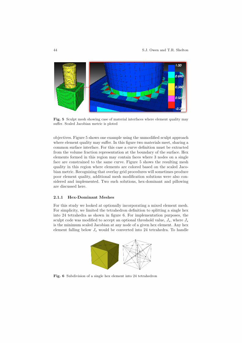
For this study we looked at optionally incorporating a mixed element mesh.For simplicity, we limited the tetrahedron definition to splitting a single hexinto 24 tetrahedra as shown in figure 6. For implementation purposes, thesculpt code was modified to accept an optional threshold value, Js, where Jsis the minimum scaled Jacobian at any node of a given hex element. Any hexelement falling below Js would be converted into 24 tetrahedra. To handle
Fig. 6 Subdivision of a single hex element into 24 tetrahedron
Validation of Grid-Based Hex Meshes 45
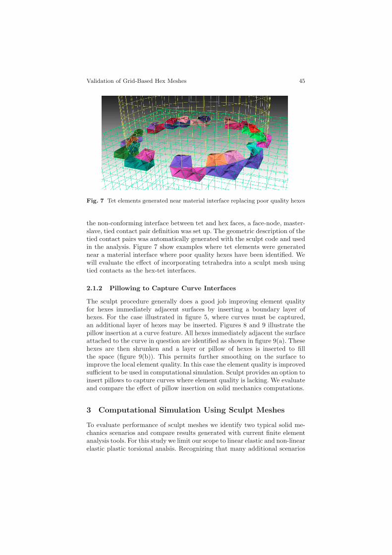
Fig. 7 Tet elements generated near material interface replacing poor quality hexes
the non-conforming interface between tet and hex faces, a face-node, master-slave, tied contact pair definition was set up. The geometric description of thetied contact pairs was automatically generated with the sculpt code and usedin the analysis. Figure 7 show examples where tet elements were generatednear a material interface where poor quality hexes have been identified. Wewill evaluate the effect of incorporating tetrahedra into a sculpt mesh usingtied contacts as the hex-tet interfaces.
2.1.2 Pillowing to Capture Curve Interfaces
The sculpt procedure generally does a good job improving element qualityfor hexes immediately adjacent surfaces by inserting a boundary layer ofhexes. For the case illustrated in figure 5, where curves must be captured,an additional layer of hexes may be inserted. Figures 8 and 9 illustrate thepillow insertion at a curve feature. All hexes immediately adjacent the surfaceattached to the curve in question are identified as shown in figure 9(a). Thesehexes are then shrunken and a layer or pillow of hexes is inserted to fillthe space (figure 9(b)). This permits further smoothing on the surface toimprove the local element quality. In this case the element quality is improvedsufficient to be used in computational simulation. Sculpt provides an option toinsert pillows to capture curves where element quality is lacking. We evaluateand compare the effect of pillow insertion on solid mechanics computations.
3 Computational Simulation Using Sculpt Meshes
To evaluate performance of sculpt meshes we identify two typical solid me-chanics scenarios and compare results generated with current finite elementanalysis tools. For this study we limit our scope to linear elastic and non-linearelastic plastic torsional analsis. Recognizing that many additional scenarios

46 S.J. Owen and T.R. Shelton
Fig. 8 Pillow inserted to capture curve feature between materials
Fig. 9 Cut-away view of figure 8 before and after pillow insertion to capture curve
Fig. 10 Sculpt mesh of torsion pin used in linear elastic simulation
may be tested, we purposely limit scope to cases critical to meet the authors’current industrial project design objectives.
For this initial study we choose a simple torsion pin shown in figure 10.In this case we model a pin fixed to a rigid body. We apply a rotational dis-placement to the end of the pin and measure the integrated torque reactionat the rigid body. Analysis is performed using the explicit quasi-static code,Sierra Solid Mechanics [16] using a linear elastic material model. Rotational

Validation of Grid-Based Hex Meshes 47
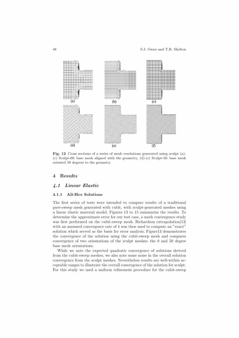
displacement is applied over a 1 second time period up to a 15 degree rota-tion. The torsion pin itself has a step down in radius at its center recognizingthat stress concentrations will develop at the re-entrant corner that must behandled by both sculpt and cubit-sweep meshes. Meshes used for this studyinclude a series of refined hex meshes generated with cubit-sweep comparedwith meshes generated with equivalent cell sizes using sculpt. The cubit-sweepmesh of the torsion pin, shown in figure 11, was generated using a decom-position plus pave and sweep approach. While there is obvious simplicity inthis model, the cubit-sweep mesh is representative of the highly user interac-tive process that is characteristic of current hex meshing practice. Figure 12shows a cross section view of the meshes generated with sculpt for this study.The sculpt meshes displayed in figure 12, show two different orientations ofthe base Cartesian grid. Figures 12(a) to (c) show the mesh aligned with theorientation of the geometry while 12(d) to (e) show a 50 degree rotation of thebase Cartesian grid with respect to the geometry. Although presumably idealto align the base Cartesian grid with the main orientation of the geometricmodel, there is no guarantee that this can be accomplished in practice. As aresult, we will look at the sensitivity of the final solution to the orientationof the base Cartesian grid. In this case we choose 10 degree increments of theCartesian grid up to 90 degrees.
Fig. 11 Series of refined meshes generated using cubit-sweep
Often expressed as one of the driving motivations for use of hexahedralelements is their ability to perform better in non-linear analysis than tetelements on similar geometry. As a result it was important to extend ourstudy to incorporate a non-linear material model that would incorporate bothelastic and plastic strain. For this case we incorporate the same test specimen,however we add additional twist to the rotational displacement up to 45degrees and decrease the time to a rapid 0.01 seconds. We also incorporatea non-linear elastic-plastic material model using an explicit solver using thesame Sierra Solid Mechanics analysis code. We measure the integrated torqueat the rigid body and compare the results at time 0.01 seconds.
48 S.J. Owen and T.R. Shelton
Fig. 12 Cross sections of a series of mesh resolutions generated using sculpt (a)-(c) Sculpt-00: base mesh aligned with the geometry, (d)-(e) Sculpt-50: base meshoriented 50 degrees to the geometry
4 Results
4.1 Linear Elastic
4.1.1 All-Hex Solutions
The first series of tests were intended to compare results of a traditionalpave-sweep mesh generated with cubit, with sculpt-generated meshes usinga linear elastic material model. Figures 13 to 15 summarize the results. Todetermine the approximate error for our test case, a mesh convergence studywas first performed on the cubit-sweep mesh. Richardson extrapolation[13]with an assumed convergence rate of 4 was then used to compute an ”exact”solution which served as the basis for error analysis. Figure13 demonstratesthe convergence of the solution using the cubit-sweep mesh and comparesconvergence of two orientations of the sculpt meshes: the 0 and 50 degreebase mesh orientations.
While we note the expected quadratic convergence of solutions derivedfrom the cubit-sweep meshes, we also note some noise in the overall solutionconvergence from the sculpt meshes. Nevertheless results are well-within ac-ceptable ranges to illustrate the overall convergence of the solution for sculpt.For this study we used a uniform refinement procedure for the cubit-sweep

Validation of Grid-Based Hex Meshes 49
Fig. 13 Log of percent error vs log ofmesh size (h) comparing mesh conver-gence for cubit-sweep mesh and two ori-entations of sculpt meshes
Fig. 14 Cross section of Von Misesstress through small diameter at reen-trant corner for linear elastic analysis
Fig. 15 Comparing percent error for integrated torque on 10 orientations of sculptmeshes with error from cubit-sweep and tet meshes
generated meshes, however used an equivalent smaller base mesh size forhigher resolutions of sculpt meshes. This may contribute to the non-uniformconvergence of the solution for sculpt meshes. The characteristic varying meshsize introduced by the insertion of the sculpt hex boundary layer may alsobe a contributing factor.
In figure 15 we record the percent error from the exact solution at time1.0, the final time step of the simulation. Results are shown for 10 orienta-tions of a sculpt mesh compared with cubit-sweep and tet meshes of similarresolution. For the results shown we utilize the coarsest mesh resolution forcubit-sweep and sculpt meshes as illustrated in figures 11(a) and 12(a),(d).For additional comparison, a tet mesh generated with Cubit’s third party
50 S.J. Owen and T.R. Shelton
tetrahedral meshing capability[5] was also generated given an input meshsize equivalent to the cubit-sweep and sculpt meshes.
We note that sculpt meshes at this resolution and for all orientations per-formed with less than about 1.25 percent error while cubit-sweep and tetmeshes performed with about 2.0 and 2.6 percent error repsectively. Al-though minimal, we also note the general trend for higher error from thesculpt meshes where the base mesh was not aligned with the maximum stressplane.
Of particular note is the superior performance of sculpt meshes for thisseries of simulations over a cubit-sweep mesh of similar resolution. We assertthat the additional resolution provided by the insertion of the sculpt bound-ary layer, provides the basis for this more accurate solution. Figure 14 showsa cross section of the computed Von Mises stress through the diameter ofthe pin at change in radius, where the x axis represents the distance fromthe cylinder axis. Computed results are overlayed for cubit-sweep, sculpt-00and sculpt-50 meshes and includes the highly refined cubit-sweep mesh forcomparison. Figure 14 illustrates that for all cases the stress gradient is high-est near the surface. Having more integration points (more elements) in thishigh gradient region produces more accurate results for the sculpt meshes ofsimilar resolution.
4.1.2 Mixed Hex-Tet Meshes
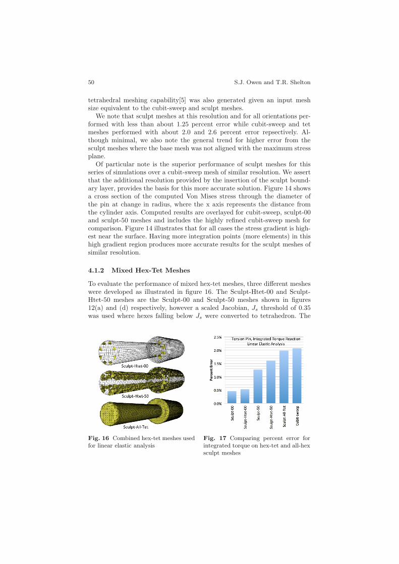
To evaluate the performance of mixed hex-tet meshes, three different mesheswere developed as illustrated in figure 16. The Sculpt-Htet-00 and Sculpt-Htet-50 meshes are the Sculpt-00 and Sculpt-50 meshes shown in figures12(a) and (d) respectively, however a scaled Jacobian, Js threshold of 0.35was used where hexes falling below Js were converted to tetrahedron. The
Fig. 16 Combined hex-tet meshes usedfor linear elastic analysis
Fig. 17 Comparing percent error forintegrated torque on hex-tet and all-hexsculpt meshes

Validation of Grid-Based Hex Meshes 51
third mesh, Sculpt-All-Tet was introduced for comparison purposes where athreshold Js of 1.0 was used, effectively converting all hexes in the mesh totets. Figure 17 shows the percent error for the three meshes at time 1.0 forthe same simulation illustrated in figure 10. Also included for comparison arethe results from Sculpt-00 and Sculpt-50 meshes and the cubit-sweep mesh.Note that in all cases, percent error fell below the results from the cubit-sweep mesh. These results indicate that minimal error is introduced into thesolution as a result of using a mixed element mesh with tied contacts over anall-hex mesh.
We should however note that even though the Sculpt-All-Tet mesh errorcame in below the cubit-sweep mesh, the mesh resolution was considerablysmaller for the Sculpt-All-Tet mesh. This is a result of the 1:24 hex to tetrefinement procedure illustrated in figure 6 where element edge lengths (h)are significantly reduced. We also observe a notable increase in run-time forthe mixed element meshes due to the tied contact interfaces and increasedresolution from the tets (figure 20).
We also note that the additional complexity of introducing tied contactsto maintain connectiveness would certainly favor an all-hex solution over amixed element solution when possible. Although not included in the cur-rent study, other alternatives such as insertion of pyramid elements [12] tomaintain connectiveness at hex-tet interfaces should also be considered.
4.1.3 Sculpt Meshes with Pillow Insertion
We also looked at the effect of introducing a pillow at an imposed surfacebetween the two radii of the pin. A cutaway of two of the meshes used in theanalysis are shown in figure 18. Results from the 10 sculpt mesh orientations
Fig. 18 Cut-away of example pillowedsculpt meshes. Two sculpt mesh orien-tations are shown.
Fig. 19 Percent error for integratedtorque on 10 orientations of pillowedsculpt meshes compared with non-pillowed meshes
52 S.J. Owen and T.R. Shelton
with pillowed surfaces are displayed in blue in figure 19. For comparison theresults from the non-pillowed sculpt meshes are also displayed in red. Wenote that in most cases, error appears to be reduced with the introduction ofthe pillowed surface and that the effect of mesh orientation on solution errorseems to be less pronounced than without the pillow.
The improved accuracy of the pillowed meshes can most likely be at-tributed to the addition of elements in the highest stress gradient region.Also, because of the case for pillowing we have selected, all orientations ofthe elements introduced by pillowing tend to align the mesh with the maxi-mum stress plane at the radius reduction in the bar. This results in a loweroverall sensitivity to base mesh orientation. The addition of pillowing in thesculpted meshes appears to provide some of the benefits of the geometry andmesh alignment obtained in the geometry-first techniques.
4.1.4 Solution Run Time
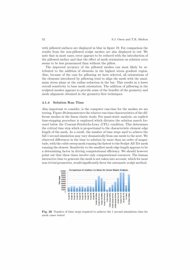
Also important to consider, is the computer run-time for the meshes we aretesting. Figure 20 demonstrates the relative run-time characteristics of the dif-ferent meshes in the linear elastic study. For quasi-static analysis, an explicittime-stepping procedure is employed which dictates the solution march for-ward below the Courant-Friedrichs-Lewy (CFL) condition. This determinesthe critical time step which is proportional to the characteristic element edgelength of the mesh. As a result, the number of time steps used to achieve thefull 1 second simulation may vary dramatically from one mesh to the next. Weobserved differences in the time to solution by more than an order of magni-tude, with the cubit-sweepmesh running the fastest to the Sculpt-All-Tet meshrunning the slowest. Sensitivity to the smallest mesh edge length appears to bea determining factor in driving computational efficiency. We should howeverpoint out that these times involve only computational resources. The humaninteractive time to generate the mesh is not taken into account, which for mostnon-trivial geometries, would significantly favor the automatic sculpt method.
Fig. 20 Number of time steps required to achieve the 1 second simulation time formesh cases tested

Validation of Grid-Based Hex Meshes 53
4.2 Non-linear Elastic-Plastic
The next step in evaluation of sculpt meshes was the introduction of a non-linear elastic-plastic material model. In this case, recognizing the singularityof the re-entrant corner on the solution, we introduced a small fillet radiusfor both the cubit-sweep and sculpt meshes as illustrated in figure 21. Resultsfrom the non-linear simulations are summarized in figures 22 to 24.
Fig. 21 Meshes used for non-linear simulations. A fillet radius is introduced at there-entrant corner to reduce effect of stress concentrations. (a) Cubit-sweep Mesh,(b) Sculpt-00, (c) Sculpt-50.
Similar to the linear-elastic case, we will define the “exact” solution us-ing Richardson extrapolation from the solutions from four uniformly refinedcubit-sweep meshes. Mesh convergence, shown in figure 22 shows reasonablebehavior where both Sculpt-00 and Sculpt-50 meshes converge at a similarrate to the Cubit-sweep generated meshes.
Figure 23 shows the error at time 0.01 with respect to the extrapolatedexact solution. Also shown is the error in the solution for the coarse cubit-sweep mesh. We note that the integrated torque at the final time step for themeshes of similar resolution were clustered within a few percentage points ofeach other. We observe that errors are considerably greater than the linear-elastic model, however seem to bracket the results from the cubit-sweep mesh.
We note that close correlation of the percent error between sculpt andcubit-sweep meshes is due to the similarity in the discretization in the interiorof the rod. Figure 24 illustrates the Von Mises stress through the cross sectionof the rod at the radius change of the bar for the coarse mesh resolutions. VonMises stress through the same cross section from the highly refined Cubit-sweep mesh is also shown for comparison. Unlike the linear-elastic case, weobserve the highest stress gradients to be concentrated on the interior wherethe discretization is the most regular for sculpt meshes. Since discretizationfor both cubit-sweep and sculpt meshes is similar on the interior, solutionresults also tend to be similar.

54 S.J. Owen and T.R. Shelton
Fig. 22 Log of percent error vs log ofmesh size (h) comparing mesh conver-gence for cubit-sweep mesh and two ori-entations of sculpt meshes for non-linearelastic-plastic analysis
Fig. 23 Comparing percent error forintegrated torque for elastic-plastic ma-terial model on 10 orientations of sculptmeshes
Fig. 24 Cross section of Von Mises stress through small diameter at radius changein bar for non-linear elastic-plastic analysis
5 Conclusions
Sculpted meshes in this study have been shown to be both usable and suffi-ciently accurate as compared to a mesh obtained through the more user inten-sive cubit-sweep mesh. Indeed we note an improvement in solution accuracyfor sculpt meshes for linear-elastic analysis due to the higher density of ele-ments near the boundary where high stress gradients are observed. In a similarmanner, we observe performance on-par for non-linear cases where high stressgradients tend to appear on the interior of the model. The sculpted mesheshave not changed the expected convergence rate as best seen in the non-linearsimulation where the discretization in the interior is virtually the same.
In this study we also observe that creation of mixed hex-tet meshes may bea viable option to avoid poor hex element quality that may result from sculpt
Validation of Grid-Based Hex Meshes 55
meshing procedures. We note that the accuracy to quantities of interest inthis study showed minimal difference over a mesh using all-hex elements. Wewould however assert that a mixed element mesh would only be requiredif positive Jacobian elements were unable to be obtained without the mixedapproach. While we limited this study to a simple 1:24 hex to tet replacement,a method that would more generally re-triangulate voids left where poorquality hexes are extracted would be advantageous. Collapsing edges of alimited number of otherwise poor quality hexes to form degenerate versionsof hex elements may also be a fruitful area to explore as demonstrated by theauthor in [15] and a reasonable alternative to mixed elements.
For the case tested we noted that the addition of pillowing in the sculptedmeshes improved element quality at the curve interfaces sufficient to producea computable quality all-hex mesh without the introduction of tet elements.As an added benefit it appeared to provide some of the advantages of thegeometry and mesh alignment obtained with a traditional pave and sweepapproach. Further generalization and improvement of the pillowing techniqueto capture curve interfaces should be explored.
Given the small variance in accuracy to cubit-sweep meshes, but virtuallyhands off mesh creation, sculpt meshes have the potential to satisfy the needsof the design community. We recognize that the range of this study covers onlya few cases for computational solid mechanics and that further work is neededto expand its scope. The current study, however indicates that the sculpt-basedmeshes, certainly provide a means for generating meshes that have fine enoughdiscretization that may require large scale computing but offer the field reso-lution required for crucial decisions.
There remains a clear case for use of precision meshing tools such as Cubit,as they offer detailed control over geometry and mesh characteristics. Indeedwe have seen highly successful and complex systems of components modeledwith such tools, however at significant cost in user time. As analysts are be-ing asked to respond more rapidly to difficult engineering design questions onlarger and more complex models, these tools cannot be counted on to scaleeffectively to meet their needs. An approach such as sculpt, that although ide-alizes andmay neglect some details of the model, has been shown to be an effec-tive alternative. Enhancements such as mixed elements as well as inclusion oflocal pillowing operations also potentially expand the effectiveness and robust-ness of the method. Because sculpt, and grid-based meshing tools in general,have the potential to be more easily generalized for parallel implementationand are more easily able to mesh arbitrarily complex geometries, results fromthis study provide additional strong motivation to expand the developmentand usage of such tools.
References
1. Ansys ICEM CFD Mesh Generation Software (2013),http://www.ansys.com/Products/Other+Products/ANSYS+ICEM+CFD

56 S.J. Owen and T.R. Shelton
2. Blacker, T.D., Meyers, R.J.: Seams and Wedges in Plastering: A 3D HexahedralMesh Generation Algorithm. Eng. with Computers 2(9), 83–93 (1993)
3. Cook, W.A., Oakes, W.R.: Mapping Methods for Generating Three-Dimensional Meshes. Computers in Mechanical Eng., 67–72 (August 1982)
4. Cubit, Geometry and Meshing Toolkit (2013), http://cubit.sandia.gov5. GHS3D: A powerful isotropic tet-mesher (2013),
http://www-roc.inria.fr/gamma/gamma/ghs3d
6. Gridgen, Reliable CFD Meshing Software (2013),http://www.pointwise.com/gridgen
7. GridPro, Superior Engineering Solutions (2013), http://www.gridpro.com8. Ito, Y., Shih, A.M., Soni, B.K.: Octree-based reasonable-quality hexahedral
mesh generation using a new set of refinement templates. International Journalfor Numerical Methods in Engineering 77(13), 1809–1833 (2009)
9. Owen, S.J.: Parallel Smoothing for Grid-Based Methods. In: 21st Int. MeshingRoundtable, Research Note (2012)
10. Owen, S.J., Staten, M.L., Sorensen, M.C.: Parallel Hex Meshing from VolumeFractions. In: Quadros, W.R. (ed.) Proceedings of the 20th International Mesh-ing Roundtable, vol. 90, pp. 161–178. Springer, Heidelberg (2011)
11. Owen, S.J., Shepherd: Embedding Features in a Cartesian Grid. In: Proc. 18thInt. Meshing Roundtable, pp. 117–138 (2009)
12. Owen, S.J., Saigal, S.: Formation of pyramid elements for hexahedra to tetra-hedra transitions. Comp. Methods in Applied Mechanics and Eng. 190(34),4505–4518 (2001)
13. Richardson, L.F.: The approximate arithmetical solution by finite differencesof physical problems including differential equations, with an application to thestresses in a masonry dam. Philosophical Transactions of the Royal Society ofLondon, Series A 210(459-470), 307–357 (1911)
14. Schneiders, R., Schindler, F., Weiler, F.: Octree-based Generation of HexahedralElement Meshes. In: Proc. 5th Int. Meshing Roundtable, pp. 205–216 (1996)
15. Shelton, T.R., Crane, N.K., Cox, J.V.: An Exploration of Accuracy and Conver-gence of the Degenerate Uniform Strain Hexahedral Element. In: Proc. ASME2013 Int. Mechanical Eng. Congress and Exposition (to appear, 2013)
16. Sierra Solid Mechanics Team, Adagio 4.22 User’s Guide, Sandia National Lab-oratories, Sandia Report SAND2011-7597 (2011)
17. Staten, M.L., Canann, S.A., Owen, S.J.: BMSWEEP: Locating Interior NodesDuring Sweeping. In: Proc. 7th Int. Meshing Roundtable, pp. 7–18 (1998)
18. Staten, M.L., Kerr, R.A., Kerr, O.S., Blacker, T.D.: Unconstrained Paving andPlastering: Progress Update. In: Proc., 15th Int. Meshing Roundtable, pp. 469–486 (2006)
19. Tam, T.K.H., Armstrong, C.G.: 2D Finite Element Mesh Generation by MedialAxis Subdivision. Advances in Eng. Software 13, 313–324 (1991)
20. Tautges, T.J., Blacker, T.D., Mitchell, S.A.: The Whisker Weaving Algorithm:A Connectivity-Based Method for Constructing All-Hex Meshes. Int. Journalfor Numerical Methods in Eng. 39, 3327–3349 (1996)
21. TrueGrid by XYZ Scientific Applications, Inc., A Mesh Generator and Pre-processor for FEA and CFD Analysis (2013), http://www.truegrid.com
22. Zhang, Y., Bajaj, C.L.: Adaptive and Quality Quadrilateral/Hexahedral Mesh-ing from Volumetric Data. Comp. Methods in Applied Mechanics and Eng. 195,942–960 (2006)


![Hexagonal Meshes with Planar Faces · 2019. 8. 30. · visual appeal[Weyl 1983]. For surface modeling in architecture, P-Hex meshes have the simplest node, since there are only three](https://img.pdfslide.us/doc/110x75/60deb57f0b7fde685a5b04f6/hexagonal-meshes-with-planar-faces-2019-8-30-visual-appealweyl-1983-for.jpg)