Embed Size (px)
Citation preview
MULTIBODY DYNAMICS 2011, ECCOMAS Thematic ConferenceJ.C. Samin, P. Fisette (eds.)
Brussels, Belgium, 4-7 July 2011
VALIDATION OF A MULTIBODY MODEL FOR AN X-BY-WIREVEHICLE PROTOTYPE THROUGH FIELD TESTING
Roland Pastorino?, Daniel Dopico?, Emilio Sanjurjo? and Miguel Ángel Naya?
?Mechanical Engineering LaboratoryUniversity of La Coruña
c/ Mendizábal, 15403 Ferrol, Spaine-mail: [email protected], [email protected], [email protected],
[email protected],web page: http://lim.ii.udc.es
Keywords: X-by-wire vehicle, vehicle prototype, MBS vehicle model, model validation, vehi-cle field testing
Abstract. Real-time simulations of full-vehicle multibody models are being successfully im-plemented in more and more cases. These simulations extend the use of multibody models tonew fields such as high-fidelity driving simulators and on-board controllers. In order to guidethe development of such multibody models, the validity of simulation’s predictions must be ex-amined. This paper intends to present and apply the first iteration step of a complete validationprocess based on the methodology developed to validate the vehicle multibody model of the Na-tional Advanced Driving Simulator. For that purpose, an X-by-wire vehicle prototype has beenbuilt to generate experimental benchmark data. After that, a self-developed real-time multibodymodel of this prototype has been programmed. In order to check the validity of this model,a self-developed driving simulator has been fed with the experimental benchmark data, thusenabling the vehicle model to repeat the test maneuvers. Comparison between experimentalbenchmark data and simulation’s predictions are very promising considering that these are thefirst validation results.
1
ISBN 978-2-8052-0116-5
Roland Pastorino, Daniel Dopico, Emilio Sanjurjo and Miguel Ángel Naya
1 INTRODUCTION
In the last decade, multibody (MBS) analysis has become a standard to speed up the devel-opment process of vehicles [1]. It is worth mentioning that multibody models in the automotiveindustry have three different purposes that imply different modeling strategies.
The first one, which is the most commonly used, is the vehicle handling analysis, where real-time execution is not required but accuracy and ease of use are essential. Numerous commercialmultibody software and self-developed multibody models have been elaborated to carry out thistask: for instance a 94 degrees of freedom model has been presented in [2], a control strategyfor vehicle trajectory tracking has been introduced in [3], flexible multibody formulations havebeen employed in [4, 5] and the gap between multibody analysis and classical vehicle dynamicshas been studied in [6].
The second purpose is related to real-time simulations. These simulations are used in Human-in-the-Loop (HITL) applications like high fidelity driving simulators or in Hardware-in-the-Loop (HIL) applications for component behavior evaluation. Real-time simulations of full-vehicle have been successfully implemented for example in the National Advanced DrivingSimulator (NADS) [7] as well as in several simulators for automotive component evaluation[8–11]. Real-time simulations are not limited to self-developed multibody models. Indeed, thecontinuous improvement of computer performance has made possible to simulate in real-timefull-vehicle multibody models using general multibody commercial software [12]. Recently, theauthors of this paper have employed real-time multibody models in automotive state observers,so extending the use of these models [13]. Even if the developed automotive observer does notrun in real-time, the research has shown that real-time automotive observers using multibodymodels will soon be available. Therefore in a near future real-time multibody models could beused on board.
The third and last purpose of multibody vehicle models is associated to crash analysis. Re-cent works have developed multibody vehicle models to study crash-worthiness [14–16].
When designing a vehicle model, reliability is a major concern. Indeed it is essential toadjust the model’s level of accuracy to the application requirements. In the automotive domain,this implies vehicle field testing to gather experimental data in order to evaluate the model’saccuracy through comparison. A. H. Hoskins claims that “Without validation of the vehicledynamics there is only speculation that a given model accurately predicts a vehicle response”[17]. Following this idea, the main aim of this research is to investigate the validity of a real-time multibody model of an X-by-wire vehicle prototype. This prototype has been developed atthe Mechanical Engineering Laboratory of the University of La Coruña with a view to its futureon board implementation with state observers. This model employs a multibody formulation(developed by this laboratory) that enables the simulation of complex systems to run in real-timewith efficiency and robustness [8].
This paper is organized as follows: Section 2 presents the vehicle field testing. In this section,the validation methodology is explained, the vehicle prototype is described and also experimen-tal data for a straight line maneuver are presented. Then, the employed multibody formulationand the self-developed vehicle model are detailed in Section 3. The driving simulator that isused to visualize the maneuvers of this model is depicted in Section 4. The first validationresults for the vehicle longitudinal dynamics are discussed in Section 5, and finally, Section 6presents the concluding remarks.
2
ISBN 978-2-8052-0116-5
Roland Pastorino, Daniel Dopico, Emilio Sanjurjo and Miguel Ángel Naya
2 FIELD TESTING USING AN X-BY-WIRE VEHICLE PROTOTYPE
2.1 The validation methodology
Simulation validity is a subjective concept that greatly depends on the objectives of the re-search. However, the general definition “A simulation will be considered to be valid if, withinsome specified operating range of the physical system, a simulation’s predictions of the system’sresponses of interest to specified input(s) agree with the actual physical system’s responses tothe same input(s) to within some specified level of accuracy”, proposed by W. R. Garrott [18],will be later applied in this research. According to this definition, it becomes clear that beforerealizing field testing with the test vehicle, the validation methodology has to be precisely de-fined. The methodology employed in this research is deeply inspired by the one developed tovalidate the NADSdyna model of the National Advanced Driving Simulator [18].
A quick summary of the three main phases of this validation methodology is given below.The first phase concerns the experimental data collection through vehicle field testing. Thedriving maneuvers have to be carefully chosen to cover a broad range of vehicle operating con-ditions: longitudinal and lateral dynamics, low and high speeds, transient and steady state, etc.Next, to discard any error due to sensor errors, external disturbances, filtering, post-processing,etc, during the measurement of vehicle dynamic responses, the experimental data can not beextracted from only one maneuver of each type. Hence, each maneuver of each type has to berepeated several times in order to average the data of each sensor, consequently increasing thequality of the experimental benchmark data. In agreement with this strategy, the test vehiclemust be properly automated to repeat the test maneuvers of interest. The set-up for automaticmaneuver repeating on the vehicle prototype developed in this research is presented in detail inSection 2.2. Aside from the improvement of the experimental benchmark data, another interest-ing advantage of data averaging over several identical maneuvers is determining the uncertaintyof the experimental testing and measurement process. According to the definition of simulationvalidity given in Section 1, this defines the maximum accuracy that the simulation’s predictionscan reach. During the first phase of this validation methodology, special attention has to be paidto maneuver repeatability. A poor repeatability would be worse than a single maneuver whilea good repeatability can greatly improve the experimental benchmark data and also define theerror zone. Finally, the last point of this first phase is an extensive post-processing that includesextraction of the desired time interval, offset removal, digital filtering, etc.
The second phase of the validation methodology focuses on the determination of vehicleparameters. Parameters related to the multibody model and also to the subsystems (brake,engine, etc) have to be identified properly. As the vehicle prototype is self-developed, thisphase is much easier than for a non self-developed vehicle.
Finally, the third phase consists in repeating the test maneuvers with the vehicle multibodymodel, in order to compare the simulation’s results with the experimental benchmark data ofthe first phase. The model has been previously configured with the parameters of the secondphase, and the model inputs are the control inputs used during the field testing. These compar-isons permit the identification of the discrepancy sources between the multibody model and thebenchmark data, with the purpose of improving the vehicle modeling and the parameter identi-fication procedures. This iterative process should be repeated until reaching the desired level ofaccuracy. The first validation results of this research are given in Section 5.
3
ISBN 978-2-8052-0116-5
Roland Pastorino, Daniel Dopico, Emilio Sanjurjo and Miguel Ángel Naya
2.2 The X-by-wire vehicle prototype
As previously mentioned, the vehicle model validation is achieved through field testing. Itcan be performed in many different ways that involve distinct vehicle types. The field testingvehicle can be a scalable vehicle, a commercial vehicle or even a vehicle prototype.
Albeit the dynamics of a scalable vehicle differ substantially from the dynamics of a full scalevehicle, its reduced cost makes it an attractive solution to evaluate MBS formulation efficiencyand MBS model accuracy.
The use of commercial vehicles might seem to be the best solution for field testing. How-ever, it carries some important drawbacks such as the difficulty to automate the vehicle forautonomous maneuvers or even the lack of information concerning the vehicle parts. To over-come these difficulties, deep modifications have to be carried out on the vehicle to instrumentit and a great amount of identification tests have to be performed on each part. All this leads toan expensive validation process.
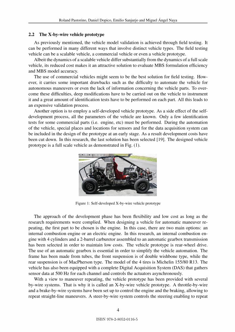
Another option is to employ a self-developed vehicle prototype. As a side effect of the self-development process, all the parameters of the vehicle are known. Only a few identificationtests for some commercial parts (i.e. engine, etc) must be performed. During the automationof the vehicle, special places and locations for sensors and for the data acquisition system canbe included in the design of the prototype at an early stage. As a result development costs havebeen cut down. In this research, the last solution has been selected [19]. The designed vehicleprototype is a full scale vehicle as demonstrated in Fig. (1).
Figure 1: Self-developed X-by-wire vehicle prototype
The approach of the development phase has been flexibility and low cost as long as theresearch requirements were complied. When designing a vehicle for automatic maneuver re-peating, the first part to be chosen is the engine. In this case, there are two main options: aninternal combustion engine or an electric engine. In this research, an internal combustion en-gine with 4 cylinders and a 2-barrel carburetor assembled to an automatic gearbox transmissionhas been selected in order to maintain low costs. The vehicle prototype is rear-wheel drive.The use of an automatic gearbox is essential in order to simplify the vehicle automation. Theframe has been made from tubes, the front suspension is of double wishbone type, while therear suspension is of MacPherson type. The model of the 4 tires is Michelin 155/80 R13. Thevehicle has also been equipped with a complete Digital Acquisition System (DAS) that gatherssensor data at 500 Hz for each channel and controls the actuators asynchronously.
With a view to maneuver repeating, the vehicle prototype has been provided with severalby-wire systems. That is why it is called an X-by-wire vehicle prototype. A throttle-by-wireand a brake-by-wire systems have been set up to control the engine and the braking, allowing torepeat straight-line maneuvers. A steer-by-wire system controls the steering enabling to repeat
4
ISBN 978-2-8052-0116-5
Roland Pastorino, Daniel Dopico, Emilio Sanjurjo and Miguel Ángel Naya
maneuvers involving the lateral dynamics of the vehicle. The choice of both the prototypecontrol inputs and the multibody model inputs are closely dependent. The multibody modelinputs can be either identical or not to the prototype control inputs depending on the objectivesof the validation.
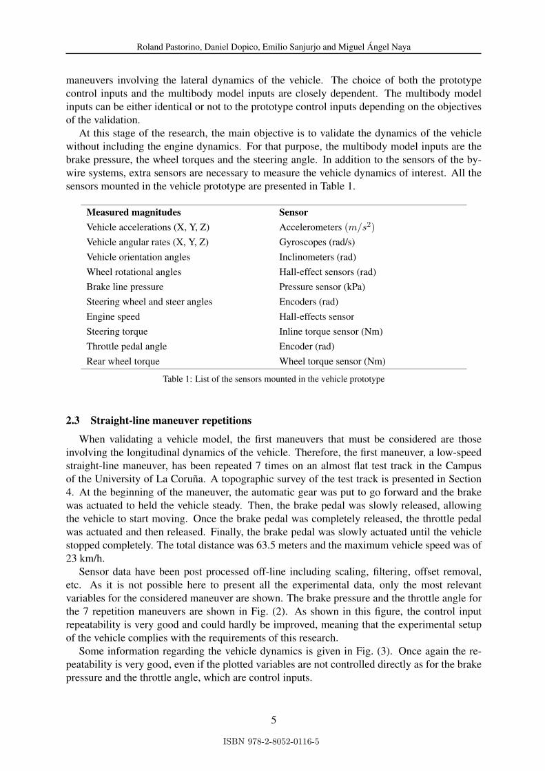
At this stage of the research, the main objective is to validate the dynamics of the vehiclewithout including the engine dynamics. For that purpose, the multibody model inputs are thebrake pressure, the wheel torques and the steering angle. In addition to the sensors of the by-wire systems, extra sensors are necessary to measure the vehicle dynamics of interest. All thesensors mounted in the vehicle prototype are presented in Table 1.
Measured magnitudes SensorVehicle accelerations (X, Y, Z) Accelerometers (m/s2)Vehicle angular rates (X, Y, Z) Gyroscopes (rad/s)Vehicle orientation angles Inclinometers (rad)Wheel rotational angles Hall-effect sensors (rad)Brake line pressure Pressure sensor (kPa)Steering wheel and steer angles Encoders (rad)Engine speed Hall-effects sensorSteering torque Inline torque sensor (Nm)Throttle pedal angle Encoder (rad)Rear wheel torque Wheel torque sensor (Nm)
Table 1: List of the sensors mounted in the vehicle prototype
2.3 Straight-line maneuver repetitions
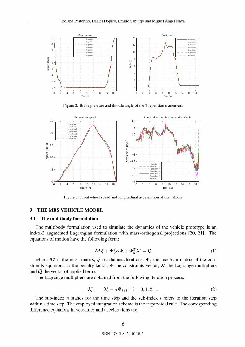
When validating a vehicle model, the first maneuvers that must be considered are thoseinvolving the longitudinal dynamics of the vehicle. Therefore, the first maneuver, a low-speedstraight-line maneuver, has been repeated 7 times on an almost flat test track in the Campusof the University of La Coruña. A topographic survey of the test track is presented in Section4. At the beginning of the maneuver, the automatic gear was put to go forward and the brakewas actuated to held the vehicle steady. Then, the brake pedal was slowly released, allowingthe vehicle to start moving. Once the brake pedal was completely released, the throttle pedalwas actuated and then released. Finally, the brake pedal was slowly actuated until the vehiclestopped completely. The total distance was 63.5 meters and the maximum vehicle speed was of23 km/h.
Sensor data have been post processed off-line including scaling, filtering, offset removal,etc. As it is not possible here to present all the experimental data, only the most relevantvariables for the considered maneuver are shown. The brake pressure and the throttle angle forthe 7 repetition maneuvers are shown in Fig. (2). As shown in this figure, the control inputrepeatability is very good and could hardly be improved, meaning that the experimental setupof the vehicle complies with the requirements of this research.
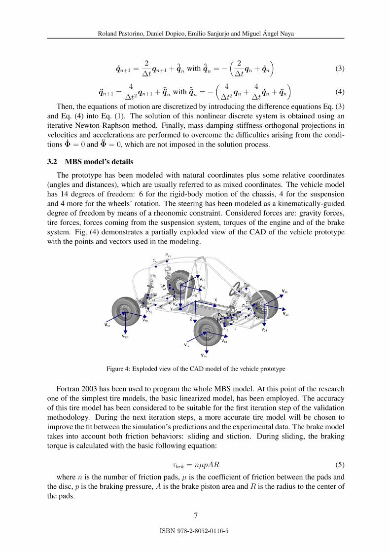
Some information regarding the vehicle dynamics is given in Fig. (3). Once again the re-peatability is very good, even if the plotted variables are not controlled directly as for the brakepressure and the throttle angle, which are control inputs.
5
ISBN 978-2-8052-0116-5
Roland Pastorino, Daniel Dopico, Emilio Sanjurjo and Miguel Ángel Naya
0 2 4 6 8 10 12 14 16 18
0
2
4
6
8
10
12
14
16
Time (s)
Pre
ssur
e (b
ars)
Brake pressure
0 2 4 6 8 10 12 14 16 18
0
2
4
6
8
10
12
14
Time (s)
Ang
le (
º)
Throttle angle
Repetition 1
Repetition 2
Repetition 3
Repetition 4
Repetition 5
Repetition 6
Repetition 7
Repetition 1
Repetition 2
Repetition 3
Repetition 4
Repetition 5
Repetition 6
Repetition 7
Figure 2: Brake pressure and throttle angle of the 7 repetition maneuvers
0 2 4 6 8 10 12 14 16 180
5
10
15
20
25
Times (s)
Spe
ed (
km/h
)
Front wheel speed
Repetition 1Repetition 2Repetition 3Repetition 4Repetition 5Repetition 6Repetition 7
0 2 4 6 8 10 12 14 16 18−3
−2.5
−2
−1.5
−1
−0.5
0
0.5
1
1.5Longitudinal acceleration of the vehicle
Time (s)
Acc
eler
atio
n (m
/s2 )
Repetition 1Repetition 2Repetition 3Repetition 4Repetition 5Repetition 6Repetition 7
Figure 3: Front wheel speed and longitudinal acceleration of the vehicle
3 THE MBS VEHICLE MODEL
3.1 The multibody formulation
The multibody formulation used to simulate the dynamics of the vehicle prototype is anindex-3 augmented Lagrangian formulation with mass-orthogonal projections [20, 21]. Theequations of motion have the following form:
Mq̈ + ΦTq αΦ + ΦT
q λ∗ = Q (1)
where M is the mass matrix, q̈ are the accelerations, Φq the Jacobian matrix of the con-straints equations, α the penalty factor, Φ the constraints vector, λ∗ the Lagrange multipliersand Q the vector of applied terms.
The Lagrange multipliers are obtained from the following iteration process:
λ∗i+1 = λ∗
i + αΦi+1 i = 0, 1, 2, ... (2)
The sub-index n stands for the time step and the sub-index i refers to the iteration stepwithin a time step. The employed integration scheme is the trapezoidal rule. The correspondingdifference equations in velocities and accelerations are:
6
ISBN 978-2-8052-0116-5
Roland Pastorino, Daniel Dopico, Emilio Sanjurjo and Miguel Ángel Naya
q̇n+1 =2
∆tqn+1 + ˆ̇qn with ˆ̇qn = −
(2
∆tqn + q̇n
)(3)
q̈n+1 =4
∆t2qn+1 + ˆ̈qn with ˆ̈qn = −
(4
∆t2qn +
4
∆tq̇n + q̈n
)(4)
Then, the equations of motion are discretized by introducing the difference equations Eq. (3)and Eq. (4) into Eq. (1). The solution of this nonlinear discrete system is obtained using aniterative Newton-Raphson method. Finally, mass-damping-stiffness-orthogonal projections invelocities and accelerations are performed to overcome the difficulties arising from the condi-tions Φ̇ = 0 and Φ̈ = 0, which are not imposed in the solution process.
3.2 MBS model’s details
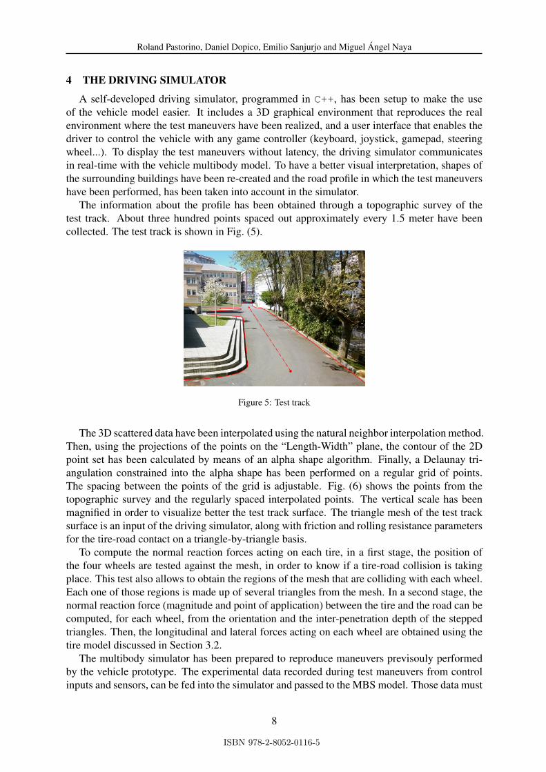
The prototype has been modeled with natural coordinates plus some relative coordinates(angles and distances), which are usually referred to as mixed coordinates. The vehicle modelhas 14 degrees of freedom: 6 for the rigid-body motion of the chassis, 4 for the suspensionand 4 more for the wheels’ rotation. The steering has been modeled as a kinematically-guideddegree of freedom by means of a rheonomic constraint. Considered forces are: gravity forces,tire forces, forces coming from the suspension system, torques of the engine and of the brakesystem. Fig. (4) demonstrates a partially exploded view of the CAD of the vehicle prototypewith the points and vectors used in the modeling.
P
V14
V22
V23
V31
Figure 4: Exploded view of the CAD model of the vehicle prototype
Fortran 2003 has been used to program the whole MBS model. At this point of the researchone of the simplest tire models, the basic linearized model, has been employed. The accuracyof this tire model has been considered to be suitable for the first iteration step of the validationmethodology. During the next iteration steps, a more accurate tire model will be chosen toimprove the fit between the simulation’s predictions and the experimental data. The brake modeltakes into account both friction behaviors: sliding and stiction. During sliding, the brakingtorque is calculated with the basic following equation:
τbrk = nµpAR (5)
where n is the number of friction pads, µ is the coefficient of friction between the pads andthe disc, p is the braking pressure, A is the brake piston area and R is the radius to the center ofthe pads.
7
ISBN 978-2-8052-0116-5
Roland Pastorino, Daniel Dopico, Emilio Sanjurjo and Miguel Ángel Naya
4 THE DRIVING SIMULATOR
A self-developed driving simulator, programmed in C++, has been setup to make the useof the vehicle model easier. It includes a 3D graphical environment that reproduces the realenvironment where the test maneuvers have been realized, and a user interface that enables thedriver to control the vehicle with any game controller (keyboard, joystick, gamepad, steeringwheel...). To display the test maneuvers without latency, the driving simulator communicatesin real-time with the vehicle multibody model. To have a better visual interpretation, shapes ofthe surrounding buildings have been re-created and the road profile in which the test maneuvershave been performed, has been taken into account in the simulator.
The information about the profile has been obtained through a topographic survey of thetest track. About three hundred points spaced out approximately every 1.5 meter have beencollected. The test track is shown in Fig. (5).
Figure 5: Test track
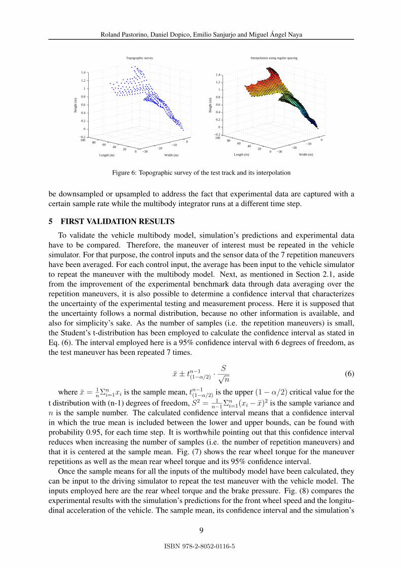
The 3D scattered data have been interpolated using the natural neighbor interpolation method.Then, using the projections of the points on the “Length-Width” plane, the contour of the 2Dpoint set has been calculated by means of an alpha shape algorithm. Finally, a Delaunay tri-angulation constrained into the alpha shape has been performed on a regular grid of points.The spacing between the points of the grid is adjustable. Fig. (6) shows the points from thetopographic survey and the regularly spaced interpolated points. The vertical scale has beenmagnified in order to visualize better the test track surface. The triangle mesh of the test tracksurface is an input of the driving simulator, along with friction and rolling resistance parametersfor the tire-road contact on a triangle-by-triangle basis.
To compute the normal reaction forces acting on each tire, in a first stage, the position ofthe four wheels are tested against the mesh, in order to know if a tire-road collision is takingplace. This test also allows to obtain the regions of the mesh that are colliding with each wheel.Each one of those regions is made up of several triangles from the mesh. In a second stage, thenormal reaction force (magnitude and point of application) between the tire and the road can becomputed, for each wheel, from the orientation and the inter-penetration depth of the steppedtriangles. Then, the longitudinal and lateral forces acting on each wheel are obtained using thetire model discussed in Section 3.2.
The multibody simulator has been prepared to reproduce maneuvers previsouly performedby the vehicle prototype. The experimental data recorded during test maneuvers from controlinputs and sensors, can be fed into the simulator and passed to the MBS model. Those data must
8
ISBN 978-2-8052-0116-5
Roland Pastorino, Daniel Dopico, Emilio Sanjurjo and Miguel Ángel Naya
−30−20
−100
020
4060
80100
−0.2
0
0.2
0.4
0.6
0.8
1
1.2
1.4
Width (m)
Interpolation using regular spacing
Length (m)
Hei
ght (
m)
−30−20
−100
020
4060
80100
−0.2
0
0.2
0.4
0.6
0.8
1
1.2
1.4
Width (m)
Topographic survey
Length (m)
Hei
ght (
m)
Figure 6: Topographic survey of the test track and its interpolation
be downsampled or upsampled to address the fact that experimental data are captured with acertain sample rate while the multibody integrator runs at a different time step.
5 FIRST VALIDATION RESULTS
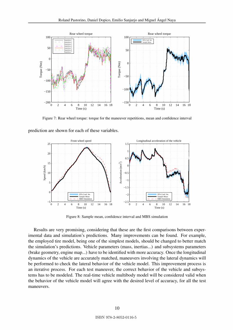
To validate the vehicle multibody model, simulation’s predictions and experimental datahave to be compared. Therefore, the maneuver of interest must be repeated in the vehiclesimulator. For that purpose, the control inputs and the sensor data of the 7 repetition maneuvershave been averaged. For each control input, the average has been input to the vehicle simulatorto repeat the maneuver with the multibody model. Next, as mentioned in Section 2.1, asidefrom the improvement of the experimental benchmark data through data averaging over therepetition maneuvers, it is also possible to determine a confidence interval that characterizesthe uncertainty of the experimental testing and measurement process. Here it is supposed thatthe uncertainty follows a normal distribution, because no other information is available, andalso for simplicity’s sake. As the number of samples (i.e. the repetition maneuvers) is small,the Student’s t-distribution has been employed to calculate the confidence interval as stated inEq. (6). The interval employed here is a 95% confidence interval with 6 degrees of freedom, asthe test maneuver has been repeated 7 times.
x̄± tn−1(1−α/2) ·
S√n
(6)
where x̄ = 1nΣn
i=1xi is the sample mean, tn−1(1−α/2) is the upper (1− α/2) critical value for the
t distribution with (n-1) degrees of freedom, S2 = 1n−1
Σni=1(xi− x̄)2 is the sample variance and
n is the sample number. The calculated confidence interval means that a confidence intervalin which the true mean is included between the lower and upper bounds, can be found withprobability 0.95, for each time step. It is worthwhile pointing out that this confidence intervalreduces when increasing the number of samples (i.e. the number of repetition maneuvers) andthat it is centered at the sample mean. Fig. (7) shows the rear wheel torque for the maneuverrepetitions as well as the mean rear wheel torque and its 95% confidence interval.
Once the sample means for all the inputs of the multibody model have been calculated, theycan be input to the driving simulator to repeat the test maneuver with the vehicle model. Theinputs employed here are the rear wheel torque and the brake pressure. Fig. (8) compares theexperimental results with the simulation’s predictions for the front wheel speed and the longitu-dinal acceleration of the vehicle. The sample mean, its confidence interval and the simulation’s
9
ISBN 978-2-8052-0116-5
Roland Pastorino, Daniel Dopico, Emilio Sanjurjo and Miguel Ángel Naya
0 2 4 6 8 10 12 14 16 18−150
−100
−50
0
50
100
Time (s)
Tor
que
(Nm
)
Rear wheel torque
0 2 4 6 8 10 12 14 16 18−200
−150
−100
−50
0
50
100
Time (s)
Tor
que
(Nm
)
Rear wheel torque
Repetition 1Repetition 2Repetition 3Repetition 4Repetition 5Repetition 6Repetition 7
95% Conf. Int.Sample Mean
Figure 7: Rear wheel torque: torque for the maneuver repetitions, mean and confidence interval
prediction are shown for each of these variables.
0 2 4 6 8 10 12 14 16 18−5
0
5
10
15
20
25
Time (s)
Spe
ed (
km/h
)
Front wheel speed
95% Conf. Int.Sample MeanMBS Simulation
0 2 4 6 8 10 12 14 16 18−2.5
−2
−1.5
−1
−0.5
0
0.5
1
1.5
Time (s)
Acc
eler
atio
n (m
/s2 )
Longitudinal acceleration of the vehicle
95% Conf. Int.Sample MeanMBS Simulation
Figure 8: Sample mean, confidence interval and MBS simulation
Results are very promising, considering that these are the first comparisons between exper-imental data and simulation’s predictions. Many improvements can be found. For example,the employed tire model, being one of the simplest models, should be changed to better matchthe simulation’s predictions. Vehicle parameters (mass, inertias...) and subsystems parameters(brake geometry, engine map...) have to be identified with more accuracy. Once the longitudinaldynamics of the vehicle are accurately matched, maneuvers involving the lateral dynamics willbe performed to check the lateral behavior of the vehicle model. This improvement process isan iterative process. For each test maneuver, the correct behavior of the vehicle and subsys-tems has to be modeled. The real-time vehicle multibody model will be considered valid whenthe behavior of the vehicle model will agree with the desired level of accuracy, for all the testmaneuvers.
10
ISBN 978-2-8052-0116-5
Roland Pastorino, Daniel Dopico, Emilio Sanjurjo and Miguel Ángel Naya
6 CONCLUSIONS
This paper focuses on the research on real-time vehicle multibody models. In order to guidethe development of such multibody models, the validity of simulation’s predictions must beexamined. This paper intends to present and apply the first iteration step of a complete validationprocess based on the methodology developed to validated the vehicle multibody model of theNational Advanced Driving Simulator. For that purpose, an X-by-wire vehicle prototype hasbeen built to generate experimental benchmark data. After that, a self-developed real-timemultibody model of this prototype has been programmed. In order to check the validity of thismodel, a self-developed driving simulator has been fed with the experimental benchmark data,thus enabling the vehicle model to repeat the test maneuvers. Comparison between experimentalbenchmark data and simulation’s predictions are very promising considering that these are thefirst validation results. Future work will focus on the improvement of the vehicle multibodymodel and its subsystems, on carrying out new test maneuvers and on the improvement of thedeveloped automotive state observers using multibody models.
7 ACKNOWLEDGMENTS
The authors would like to thank the Spanish Ministry of Science and Innovation and ERDFfunds through the grant TRA2009-09314 for its support in this research.
REFERENCES
[1] E. Fischer. Standard multi-body system software in the vehicle development process.Proceedings of the institution of mechanical engineers, part K: journal of multi-body dy-namics, 221:13–20, 2007.
[2] S. Hegazy, H. Rahnejat, and K. Hussain. Multi-body dynamics in full-vehicle handlinganalysis under transient manoeuvre. Vehicle System Dynamics, 34:1–24, July 2000.
[3] P. Antos and J. A. C. Ambrósio. A control strategy for vehicle trajectory tracking usingmultibody models. Multibody System Dynamics, 11(4):365–394, 2004.
[4] J. A. C Ambrósio and J. P. C. Goncalves. Complex flexible multibody systems with appli-cation to vehicle dynamics. Multibody System Dynamics, 6(2):163–182, 2001.
[5] J. Cuadrado, R. Gutiérrez, M. A. Naya, and M. González. Experimental validation of aflexible MBS dynamic formulation through comparison between measured and calculatedstresses on a prototype car. Multibody System Dynamics, 11(2):147–166, 2004.
[6] M. Blundell and D. Harty. The multibody systems approach to vehicle dynamics. Elsevier,September 2004.
[7] G. J. Heydinger, M. K. Salaani, W. R. Garrott, and P. A. Grygier. Vehicle dynamicsmodelling for the National Advanced Driving Simulator. In Proceedings of the institutionof mechanical engineers, part D: journal of automobile engineering, volume 216, pages307–318, 2002.
[8] M. A. Naya, D. Dopico, J. A . Pérez, and J. Cuadrado. Real-time multi-body formulationfor virtual-reality-based design and evaluation of automobile controllers. Proceedings ofthe institution of mechanical engineers, part K: journal of multi-body dynamics, 221(2):261–276, 2007.
11
ISBN 978-2-8052-0116-5
Roland Pastorino, Daniel Dopico, Emilio Sanjurjo and Miguel Ángel Naya
[9] K. Kim, J. Kim, K. S. Huh, K. Yi, and D. Cho. A real-time multi-vehicle simulator forlongitudinal controller design. Vehicle System Dynamics, 44(5):369 – 386, May 2006.
[10] S. S. Kim and W. H. Jeong. Real-time multibody vehicle model with bush complianceeffect using quasi-static analysis for hils. Multibody System Dynamics, 22(4):367–382,May 2009.
[11] W. Rulka and E. Pankiewicz. MBS approach to generate equations of motions for HiL-simulations in vehicle system dynamics. Multibody System Dynamics, 14(3-4):367–386,Dic. 2005.
[12] M. W. Sayers. Vehicle models for RTS applications. Vehicle System Dynamics, 32(4-5):421 – 438, November 1999.
[13] J. Cuadrado, D. Dopico, J. A. Pérez, and R. Pastorino. Automotive observers based onmultibody models and the Extended Kalman Filter. Multibody System Dynamics, 2011.doi: 10.1007/s11044-011-9251-1.
[14] M. Carvalho and J. A. C. Ambrósio. Identification of multibody vehicle models for crashanalysis using an optimization methodology. Multibody System Dynamics, 24(3):325–345,october 2010.
[15] J. A. C. Ambrósio. Crash analysis and dynamical behaviour of light road and rail vehicles.Vehicle System Dynamics, 43(6-7):385–411, 2005.
[16] L. Sousa, P. Verissimo, and J. Ambrósio. Development of generic multibody road vehi-cle models for crashworthiness. Multibody System Dynamics, 19(1-2):133–158, february2008.
[17] A.H. Hoskins and M. El-Gindy. Technical report: Literature survey on driving simulatorvalidation studies. International Journal of Heavy Vehicle Systems, 13(3):241 – 252, 2006.
[18] W. Riley Garrott, Paul A. Grygier, Jeffrey P. Chrstos, Gary J. Heydinger, Kamel M.Salaani, J. Gavin Howe, and Dennis A. Guenther. Methodology for validating the NationalAdvanced Driving Simulator Vehicle Dynamics (NADSdyna). SAE, 106(6):882–894, Feb.1997.
[19] R. Pastorino, Luaces A. Naya, M. A., and J. Cuadrado. X-by-wire vehicle prototype:automatic driving maneuver implementation for real-time MBS model validation. In Pro-ceedings of the 515th EUROMECH Colloquium, Blagoevgrad, Bulgaria, 2010.
[20] J. Cuadrado, R. Gutiérrez, M. A. Naya, and P. Morer. A comparison in terms of accuracyand efficiency between a MBS dynamic formulation with stress analysis and a non-linearFEA code. Int. Journal for Numerical Methods in Engineering, 51(9):1033–1052, 2001.
[21] J. Cuadrado, D. Dopico, M. A. Naya, and M. González. Penalty, semi-recursive and hybridmethods for MBS real-time dynamics in the context of structural integrators. MultibodySystem Dynamics, 12(2):117–132, 2004.
12
ISBN 978-2-8052-0116-5