Embed Size (px)
Citation preview
International Journal of Software Engineering & Applications (IJSEA), Vol.9, No.4, July 2018
DOI:10.5121/ijsea.2018.9407 101
VALIDATION AND VERIFICATION OF SYSML
ACTIVITY DIAGRAMS USING HOARE LOGIC
Yufei Yin1, Shaoying Liu1 and Yixiang Chen2
1Hosei University, Tokyo, Japan 2East China Normal University, Shanghai, China
Abstract SysML diagrams are significant medium using for supporting software lifecycle management. The existing
TBFV method is designed for error detection with full automation efficiency, only for code. For verifying
the correctness of SysML diagram, we applying TBFV method into SysML diagram. In this paper, we
propose a novel technique that makes use of Hoare Logic and testing to verify whether the SysML diagrams
meet the requirement, called TBFV-M. This research can improve the correctness of SysML diagram,
which is likely to significantly affect the reliability of the implementation. A case study is conducted to show
its feasibility and used to illustrate how the proposed method is applied; and discussion on potential
challenges to TBFV-M is also presented.
Keywords SysML activity diagrams, TBFV, test path generation, formal verification of SysML diagram.
1. INTRODUCTION
With the increasing scale of the software system, people prefer to use the Model-Based Systems Engineering (MBSE) instead of the traditional software engineering. MBSE [1] refers to an introduction to applying the modelling method into the system engineering and using the model to support activities. The systems modelling language SysML [2, 3] can support effective use of MBSE. In MBSE, SysML models are often used as the design for code. Therefore, its correctness in terms of meeting the users’ requirements becomes critical to ensure the high reliability of the code. Unfortunately, to the best of our knowledge from the literature, there are few tools to support the verification of SysML models [4, 5] in particular rigorous ways of verification. Testing-Based Formal Verification (TBFV) proposed by Liu [6-8] shows an efficient method unitizing Hoare Logic to strengthen testing for error detection for code. The superiority of TBFV to both testing and formal verification is that it can verify the correctness of all traversed paths and can be performed automatically because the derivation of invariants from iterations is no longer needed. However, the current TBFV is mainly designed for sequential code. In this paper, we discuss how the existing TBFV can be applied to SysML models for their verification and we use TBFV-M (testing-based formal verification for models) to represent the newly developed approach. Since SysML Activity Diagrams can model the systems dynamic behaviour and describe complex control and parallel activities, our discussion in this paper focuses on the activity diagrams.
International Journal of Software Engineering & Applications (IJSEA), Vol.9, No.4, July 2018
102
The essential idea of TBFV-M is as follows. All of the functional scenarios are first extracted from a given formal specification defining the users’ requirements. Meanwhile, test paths aregenerated from corresponding SysML Activity Diagrams waiting to be verified. Then, test paths are matched with functional scenarios by a given algorithm. After this, the pre-condition of the test path is automatically derived by applying the assignment axiom in Hoare logic based on the functional scenario. Finally, the implication of the pre-condition of the specification with the guard condition of the functional scenario to the derived pre-condition of the path is verified which concerns the accuracy of the activity diagram. The remainder of the article will detail the TBFV-M method. Section 2 displays related work. Section 3 and section 4 introduce testing, Hoare Logic and TBFV approach separately. And section 5 shows the main principle of TBFV-M method, which demonstrates the unique parts of TBFV-M. Section 6 uses a dedicated example to express the process. Section 7 shows the evaluation result and section 8 conclude the paper
2. Related Work
The process of putting forward TBFV-M method requires information of multiple angles. While establishing the TBFV-M method, we inquired the existing work in extensive range, including testing-based verification, requirements verification, verification using Hoare Logic and test case generation. For better understanding of our research, we list them separately.
2.1. Testing-Based Verification Considering the shortcoming of Formal verification based on Hoare logic hard to automate, Liu [6] proposed the TBFV (Testing-Based Formal Verification) method by combining specification-based testing with formal verification. This method not only has the advantages of the test which can be automated, but also the efficiency of error detection with formal verification. Liu also designed a group of algorithms [9] for test cases generation from formal specification written with SOFL [10]. A supporting tool [8] is also developed.
Franco Raimondi [11] addressed the problem of verifying planning domains written in the Planning Domain Definition Language (PDDL). First, he translated test cases into planning goals, then verified planning domains using the planner. A tool PDVer is also generated, which can produce planning goals from requirements automatically, according to coverage conditions.
2.2. Requirements Verification Stefano Marrone [12, 13] designed a Model-Driven Engineering approach, in which formal models are constructed and test cases are generated from UML model, utilizing UML profiles and model transformation algorithms, automatically. As they claimed, formal models can be used for quantitative analysis of non-functional properties, while test cases can be used for model checking.
Feng Liang [14] proposed a vVDR (Virtual Verification of Designs against Requirements) approach for verifying a system with its requirement. In his research, the system is modeled in Modelica, and requirement verification scenarios are specified in ModelicaML, an UML profile
International Journal of Software Engineering & Applications (IJSEA), Vol.9, No.4, July 2018
103
and a language extension for Modelica. However, the deficiency appears when the number of requirements and scenarios increase.
2.3. Verification Using Hoare Logic
Ralf Sasse [15] designed a tool called Java+ITP to verify a subset of the Java language. During the verification process, Maude-based continuation passing style (CPS) is used to rewrite the logical semantics of Java, and they also developed CPSbased Hoare Logic rules to justify the correctness of the rewritten fragment. Magnus O. Myreen [16] used Hoare Logic to deal with machine code. They designed a mechanized Hoare-style programming logic framework to accommodate the restrictions and features present in real machine-code, such as finite memory, data and code in the same memory space. ARM machine-code now can be verified using the proposed logic.
2.4. Test Case Generation Debasish Kundu [17] used a more abstract perspective to treat AD than ever before and they took it as corresponding use case. They first transformed the activity diagram into an activity graph and design an algorithm generating test cases from the activity graph automatically. In their article, they claimed that the disadvantage of the current algorithm is that their method can only handle one use case at a time. Jonathan Lasalle [18] established VETESS, which is a tool chain that can generate test case for embedded systems automatically. By leveraging existing test case generation and test path extraction tools, VETESS can extract valid information from UML or SysML models and execute functional test case automatedly. Chen Mingsong [19] proposed an approach to instrument a JAVA program for the specific UML activity diagram and run the instrumented JAVA program to generate test cases according to the algorithm he designed. Finally, he used the program execution result to analyze the corresponding UML activity diagram. Chen also developed a tool named UMLTGF to support the above process. For disposing of the problem of verifying SysML Activity Diagram, we consulted the TBFV method and proposed TBFV-M as a solution. TBFV approach has an advantage over formal correctness verification based on Hoare Logic in verifying the realistic program systems, because Functional scenario-based testing can make the process of error detection be automatically performed. However, it only deals with code. So, we apply the method into SysML Models, and created TBFV-M. Model is more intuitive than a formal specification because it requires less relevant background knowledge and is easier to communicate with customers.
3. INTRODUCTION OF TESTING AND HOARE LOGIC
Test Case generation technique utilize SysML modes for generating test cases for detecting programs errors. It is easy to be performed automatically, but the error may still exist in the programs. Formal verification, based Hoare Logic, provides a possibility to prove the correctness for programs. However, due to the complexity in deriving invariant, it is rarely used in the
International Journal of Software Engineering & Applications (IJSEA), Vol.9, No.4, July 2018
industry world. We put forward a novel approach to verifying a SysML Activity Diagram by combining test case generation with Hoare Logic based formal verification. In this section, we briefly introduce the relevant parts of test case discussion of the TBFV-M method.
3.1. TESTING
For make the definition of testing more clearly, this section will introduce some knowledge, including the formal definition of activity diagram, test case andhierarchically.
3.1.1. ACTIVITY DIAGRAM Activity Diagram Formal Definition [2] can be represented as: Node is a set of nodes of which definition as follow:
Node = {InitialNode; FlowFinalNode; ActivityFinalNode; ActionNode; ActivityNode; ForkNode; JoinNode; DecisionNode; MergeNode; RecieveSignalNode; SendSignalNode}
Edges defines the relationship between nodes such that:
3.1.2. TEST CASE
From a global view, test case based on the SysML activity diagram consists of test path and test data. And the definition is as followed: TC(AD) = (Path; Data) For activity diagram, test scenario consists of a series of actions and edges in the diagram. Based on the formal definition of the activity diagram given above, the test path is defined as follow:
In this formula, ai means node, ti means edge. In this case, a test path is a set of nodes, starting from node a1 and ending with node an through the transition edges t2 … tn. For activity dia1 and an represent the initial node and final node, respectively.
International Journal of Software Engineering & Applications (IJSEA), Vol.9, No.4, July 2018
industry world. We put forward a novel approach to verifying a SysML Activity Diagram by combining test case generation with Hoare Logic based formal verification. In this section, we briefly introduce the relevant parts of test case generation and Hoare Logic to pave the way for
M method.
For make the definition of testing more clearly, this section will introduce some knowledge, including the formal definition of activity diagram, test case and test coverage criteria,
Activity Diagram Formal Definition [2] can be represented as:
AD = (Node; Edge)
Node is a set of nodes of which definition as follow:
Node = {InitialNode; FlowFinalNode; ActivityFinalNode; ActionNode; ActivityNode; ForkNode; JoinNode; DecisionNode; MergeNode; RecieveSignalNode; SendSignalNode}
Edges defines the relationship between nodes such that:
From a global view, test case based on the SysML activity diagram consists of test path and test data. And the definition is as followed:
TC(AD) = (Path; Data)
For activity diagram, test scenario consists of a series of actions and edges in the diagram. Based on the formal definition of the activity diagram given above, the test path is defined as follow:
In this formula, ai means node, ti means edge. In this case, a test path is a set of nodes, starting from node a1 and ending with node an through the transition edges t2 … tn. For activity dia1 and an represent the initial node and final node, respectively.
International Journal of Software Engineering & Applications (IJSEA), Vol.9, No.4, July 2018
104
industry world. We put forward a novel approach to verifying a SysML Activity Diagram by combining test case generation with Hoare Logic based formal verification. In this section, we
generation and Hoare Logic to pave the way for
For make the definition of testing more clearly, this section will introduce some knowledge, test coverage criteria,
(1)
Node = {InitialNode; FlowFinalNode; ActivityFinalNode; ActionNode; ActivityNode; ForkNode; JoinNode; DecisionNode; MergeNode; RecieveSignalNode; SendSignalNode} (2)
(3)
From a global view, test case based on the SysML activity diagram consists of test path and test
(4)
For activity diagram, test scenario consists of a series of actions and edges in the diagram. Based on the formal definition of the activity diagram given above, the test path is defined as follow:
(5)
(6)
(7)
In this formula, ai means node, ti means edge. In this case, a test path is a set of nodes, starting from node a1 and ending with node an through the transition edges t2 … tn. For activity diagram,
International Journal of Software Engineering & Applications (IJSEA), Vol.9, No.4, July 2018
105
3.1.3. TEST COVERAGE CRITERIA
For software, the adequacy measurement of testing is reflected in the rate of coverage and effectiveness of the test case. These coverage criteria ensure the sufficiency of testing and provide implications for the test case generation algorithm. Here are four test coverage criteria used in our design, for test case generation of SysML activity diagram [19,25,26]: • Action coverage criteria: In software testing process, testers are often required to generate test cases to execute every action in the program at least once.
• Edge coverage criteria: In software testing process, testers are often required to generate test cases to pass every edge in the program at least once.
• Path coverage criteria: These coverage criteria require that all the execution paths from the programs entry to its exit are executed during testing.
• Branch coverage criteria: These coverage criteria generate test cases from each reachable decision made true by some actions and false by others. 3.2. HOARE LOGIC Hoare Logic is a formal system developed by C. A. R. Hoare [27, 28], and it is designed for the proof of partial correctness of a program. In Hoare Logic, the Hoare Triple [29] is best known and is also referenced in our method. The Hoare triple is of this form
{P} C {Q} (8) where P and Q are assertions and C is a command. P is named the pre-condition, which is a predicate expression describing the initial states and Q the post-condition, which is also a predicate expression describing the final states. Hoare also established necessary axioms to define the semantics of each program construct, including axiom of assignment, rules of consequence, axioms of composition, axioms of alternation, iteration and block. Axiom of assignment is used in our work, so we will briefly introduce it:
{Q(E\x)} x:=E {Q} (9)
where x is a variable identifier, E is an expression of a programming language without side effects, but possibly containing x, Q[E\x] is a predicate resulting from Q by substituting E for all occurrences of x in Q.
4. TBFV
TBFV combined specification-based testing and Hoare Logic-based formal verification to detect errors of programs. The essential idea is first to use specification-based testing to discover all traversed program paths and then to use Hoare logic to prove their correctness. Testing is a practical technique for detecting program errors. A strong point of testing superior to formal correctness verification is that it is much easier to be performed automatically if formal
International Journal of Software Engineering & Applications (IJSEA), Vol.9, No.4, July 2018
specifications are adopted [20], but a weak point is that existing errstill not be uncovered even if it has been traversed using a test case. Formal verification has a possibility to prove the correctness of a program. However, it not only need professional knowledge to process iterations, but also world. TBFV takes advantage of testing, realized full automation for error detection efficiency. TBFV is a specific specification-based testing approach that takes both the precondition and postconditiinto account in test case generation [21]. After acquiring all the test path of the program, Hoare Logic will help to give a formal proof for each path, which guarantees the comprehensiveness of verification.
TBFV first generates a test case from eachspecification using pre- and postspecification can be automatically transformed into an equivalent disjunction of functional scenarios and each scenario defines an independent function of the corresponding program. To precisely describe this strategy, we first need to introduce functional scenario. Spre and Spost denote the pre- and post-conditions of operation S. Let:
Gi and Di (i 1, …, n) are two predicates, called guard condition and defining condition, respectively. The definition of functional scenarios and FSF (functional scenario form) are list below:
FSF = (S
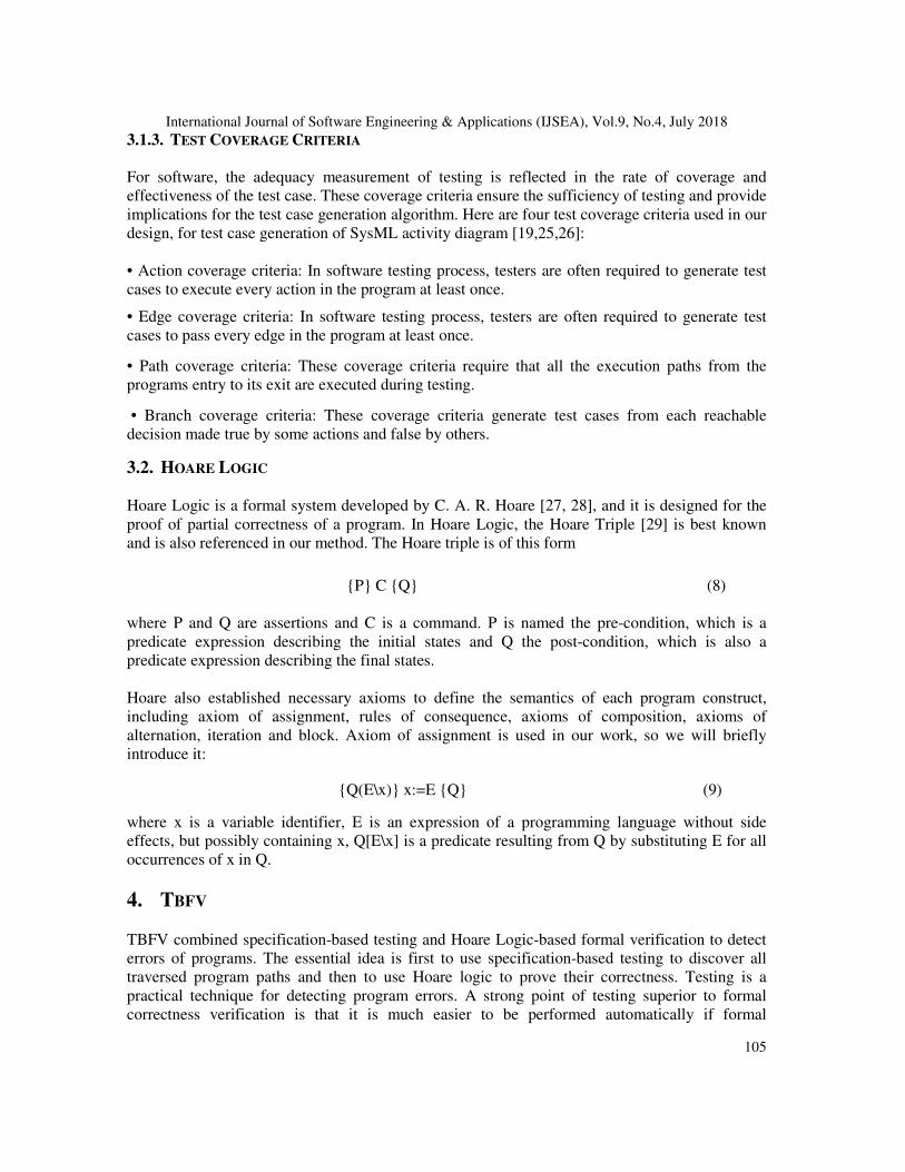
In the definition of functional scenario, Spre Gi Di is treated as a scenario, as it defines a specific condition of a program. A systematic transformation procedure, algorithm, and software tool support for deriving an FSF from a predeveloped in our previous work [22]. Let us make a small example to explain this definition more impressively. Evaluation is an operation, taking the mark as input and trying to evaluating whether it is deserved to pass thexamination. And the qualifying line is 60, which means if the mark is over 60, you pass; otherwise, you will be marked as false. The specification is written in SOFL specification language and it shows below:
International Journal of Software Engineering & Applications (IJSEA), Vol.9, No.4, July 2018
specifications are adopted [20], but a weak point is that existing errors on a program path may still not be uncovered even if it has been traversed using a test case. Formal verification has a possibility to prove the correctness of a program. However, it not only need professional knowledge to process iterations, but also consume time, which it has low usage in the industry
TBFV takes advantage of testing, realized full automation for error detection efficiency. TBFV is based testing approach that takes both the precondition and postconditi
into account in test case generation [21]. After acquiring all the test path of the program, Hoare Logic will help to give a formal proof for each path, which guarantees the comprehensiveness of
TBFV first generates a test case from each functional scenario, derived from the formal and post-conditions, to run the program. A pre-post style formal
specification can be automatically transformed into an equivalent disjunction of functional defines an independent function of the corresponding program.
To precisely describe this strategy, we first need to introduce functional scenario. Spre and Spost conditions of operation S. Let:
SPOST = (G1 D1) (G2 D2) … (GN DN)
Gi and Di (i 1, …, n) are two predicates, called guard condition and defining condition, respectively. The definition of functional scenarios and FSF (functional scenario form) are list
Functional Scenario = Spre Gi Di
FSF = (Spre G1 D1) (Spre G2 D2) … (Spre Gn Dn
In the definition of functional scenario, Spre Gi Di is treated as a scenario, as it defines a specific condition of a program. A systematic transformation procedure, algorithm, and software tool support for deriving an FSF from a pre-post style specification written in SOFL have been developed in our previous work [22].
Let us make a small example to explain this definition more impressively. Evaluation is an operation, taking the mark as input and trying to evaluating whether it is deserved to pass thexamination. And the qualifying line is 60, which means if the mark is over 60, you pass; otherwise, you will be marked as false. The specification is written in SOFL specification
International Journal of Software Engineering & Applications (IJSEA), Vol.9, No.4, July 2018
106
ors on a program path may still not be uncovered even if it has been traversed using a test case. Formal verification has a possibility to prove the correctness of a program. However, it not only need professional
consume time, which it has low usage in the industry
TBFV takes advantage of testing, realized full automation for error detection efficiency. TBFV is based testing approach that takes both the precondition and postcondition
into account in test case generation [21]. After acquiring all the test path of the program, Hoare Logic will help to give a formal proof for each path, which guarantees the comprehensiveness of
functional scenario, derived from the formal post style formal
specification can be automatically transformed into an equivalent disjunction of functional defines an independent function of the corresponding program.
To precisely describe this strategy, we first need to introduce functional scenario. Spre and Spost
(10)
Gi and Di (i 1, …, n) are two predicates, called guard condition and defining condition, respectively. The definition of functional scenarios and FSF (functional scenario form) are list
(11)
n) (12)
In the definition of functional scenario, Spre Gi Di is treated as a scenario, as it defines a specific condition of a program. A systematic transformation procedure, algorithm, and software tool
tion written in SOFL have been
Let us make a small example to explain this definition more impressively. Evaluation is an operation, taking the mark as input and trying to evaluating whether it is deserved to pass the examination. And the qualifying line is 60, which means if the mark is over 60, you pass; otherwise, you will be marked as false. The specification is written in SOFL specification
International Journal of Software Engineering & Applications (IJSEA), Vol.9, No.4, July 2018
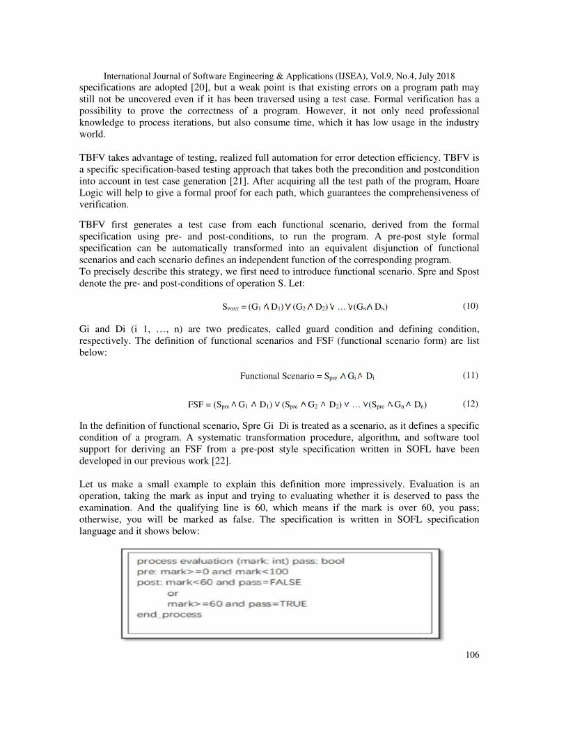
The specification states that the input mark must be in the range from 100 to 0 and the output pass is a bool type. According to the definition proposed before, three functional scenarios can be derived from this formal specification, as shown below.
The correctness of the path with respect to the preunlikely to be established by means of testing. This deficiency can be eliminated by repeatedly applying the axiom for assignment in Hoare logic. So, we need to fodefinition are below:
P is called a program segment, which consists of decision (i.e., a predicate), an assignment, a return statement, or a printing statement. It means that if the precondition Gi of the program are both true before path P is execP will be true on its termination. Finally, repeatedly apply the axiom for assignment to derive a pre-assertion, denoted by Ppre. And the correctness of the specific path is transformed into the implication Spre ∧ Gi → Ppre. If the implication can be proved, it means that no error exists on the path; otherwise, it indicates the existence of some error on the path.
5. PRINCIPLE OF TBFV- Model-Based Systems Engineering (MBSE) combines process and analysis with the last decade, the model-driven approach for software development has gained a growing interest of both industry and research communities as it promises easy automation and reduced time to market [23]. Because of the graphical notation fedge diagrams, SysML model addresses the ease of adoption amongst engineers [24].
International Journal of Software Engineering & Applications (IJSEA), Vol.9, No.4, July 2018
The specification states that the input mark must be in the range from 100 to 0 and the output pass is a bool type. According to the definition proposed before, three functional scenarios can be derived from this formal specification, as shown below.
The correctness of the path with respect to the pre-condition and the functional scenario is unlikely to be established by means of testing. This deficiency can be eliminated by repeatedly applying the axiom for assignment in Hoare logic. So, we need to form path triple and the
{SPRE GI}P { DI}
P is called a program segment, which consists of decision (i.e., a predicate), an assignment, a return statement, or a printing statement. It means that if the pre-condition Spre and the guard condition Gi of the program are both true before path P is executed, the post-condition Di of path P will be true on its termination. Finally, repeatedly apply the axiom for assignment to derive a
assertion, denoted by Ppre. And the correctness of the specific path is transformed into the pre. If the implication can be proved, it means that no error exists on
the path; otherwise, it indicates the existence of some error on the path.
-M
Based Systems Engineering (MBSE) combines process and analysis with architecture. In driven approach for software development has gained a growing
interest of both industry and research communities as it promises easy automation and reduced time to market [23]. Because of the graphical notation for defining system design as nodes and edge diagrams, SysML model addresses the ease of adoption amongst engineers [24].
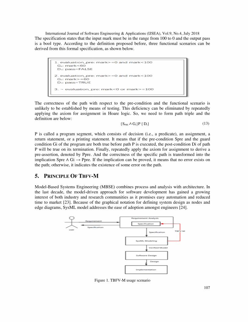
Figure 1. TBFV-M usage scenario
International Journal of Software Engineering & Applications (IJSEA), Vol.9, No.4, July 2018
107
The specification states that the input mark must be in the range from 100 to 0 and the output pass is a bool type. According to the definition proposed before, three functional scenarios can be
condition and the functional scenario is unlikely to be established by means of testing. This deficiency can be eliminated by repeatedly
rm path triple and the
(13)
P is called a program segment, which consists of decision (i.e., a predicate), an assignment, a condition Spre and the guard
condition Di of path P will be true on its termination. Finally, repeatedly apply the axiom for assignment to derive a
assertion, denoted by Ppre. And the correctness of the specific path is transformed into the pre. If the implication can be proved, it means that no error exists on
architecture. In driven approach for software development has gained a growing
interest of both industry and research communities as it promises easy automation and reduced or defining system design as nodes and
edge diagrams, SysML model addresses the ease of adoption amongst engineers [24].
International Journal of Software Engineering & Applications (IJSEA), Vol.9, No.4, July 2018
108
During the Model-Driven process, model is an important medium for the Model based system engineering development. The TBFV-M method is mainly used to verify whether SysML Activity Diagram model meets the user's requirements written in SOFL (Structured-Objectoriented-Formal Language). The TBFV-M method takes the specification describing the users’ requirements and the SysML Activity Diagram model as input and verifies the correctness of the SysML model according to the specification. The procedure of TBFV-M is illustrated in Figure2
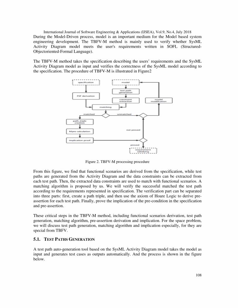
Figure 2. TBFV-M processing procedure
From this figure, we find that functional scenarios are derived from the specification, while test paths are generated from the Activity Diagram and the data constraints can be extracted from each test path. Then, the extracted data constraints are used to match with functional scenarios. A matching algorithm is proposed by us. We will verify the successful matched the test path according to the requirements represented in specification. The verification part can be separated into three parts: first, create a path triple, and then use the axiom of Hoare Logic to derive pre-assertion for each test path. Finally, prove the implication of the pre-condition in the specification and pre-assertion. These critical steps in the TBFV-M method, including functional scenarios derivation, test path generation, matching algorithm, pre-assertion derivation and implication. For the space problem, we will discuss test path generation, matching algorithm and implication especially, for they are special from TBFV.
5.1. TEST PATHS GENERATION A test path auto-generation tool based on the SysML Activity Diagram model takes the model as input and generates test cases as outputs automatically. And the process is shown in the figure below.
International Journal of Software Engineering & Applications (IJSEA), Vol.9, No.4, July 2018
109
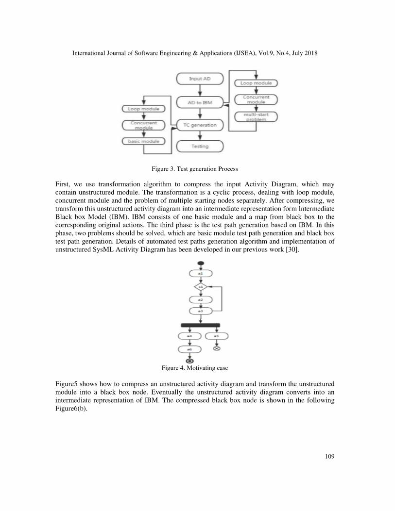
Figure 3. Test generation Process
First, we use transformation algorithm to compress the input Activity Diagram, which may contain unstructured module. The transformation is a cyclic process, dealing with loop module, concurrent module and the problem of multiple starting nodes separately. After compressing, we transform this unstructured activity diagram into an intermediate representation form Intermediate Black box Model (IBM). IBM consists of one basic module and a map from black box to the corresponding original actions. The third phase is the test path generation based on IBM. In this phase, two problems should be solved, which are basic module test path generation and black box test path generation. Details of automated test paths generation algorithm and implementation of unstructured SysML Activity Diagram has been developed in our previous work [30].
Figure 4. Motivating case
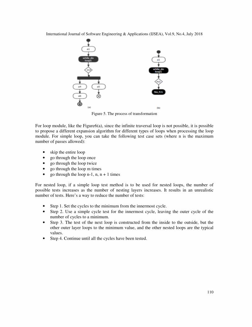
Figure5 shows how to compress an unstructured activity diagram and transform the unstructured module into a black box node. Eventually the unstructured activity diagram converts into an intermediate representation of IBM. The compressed black box node is shown in the following Figure6(b).
International Journal of Software Engineering & Applications (IJSEA), Vol.9, No.4, July 2018
110
Figure 5. The process of transformation
For loop module, like the Figure6(a), since the infinite traversal loop is not possible, it is possible to propose a different expansion algorithm for different types of loops when processing the loop module. For simple loop, you can take the following test case sets (where n is the maximum number of passes allowed):
• skip the entire loop
• go through the loop once
• go through the loop twice
• go through the loop m times
• go through the loop n-1, n, n + 1 times For nested loop, if a simple loop test method is to be used for nested loops, the number of possible tests increases as the number of nesting layers increases. It results in an unrealistic number of tests. Here’s a way to reduce the number of tests:
• Step 1. Set the cycles to the minimum from the innermost cycle.
• Step 2. Use a simple cycle test for the innermost cycle, leaving the outer cycle of the number of cycles to a minimum.
• Step 3. The test of the next loop is constructed from the inside to the outside, but the other outer layer loops to the minimum value, and the other nested loops are the typical values.
• Step 4. Continue until all the cycles have been tested.
International Journal of Software Engineering & Applications (IJSEA), Vol.9, No.4, July 2018
111
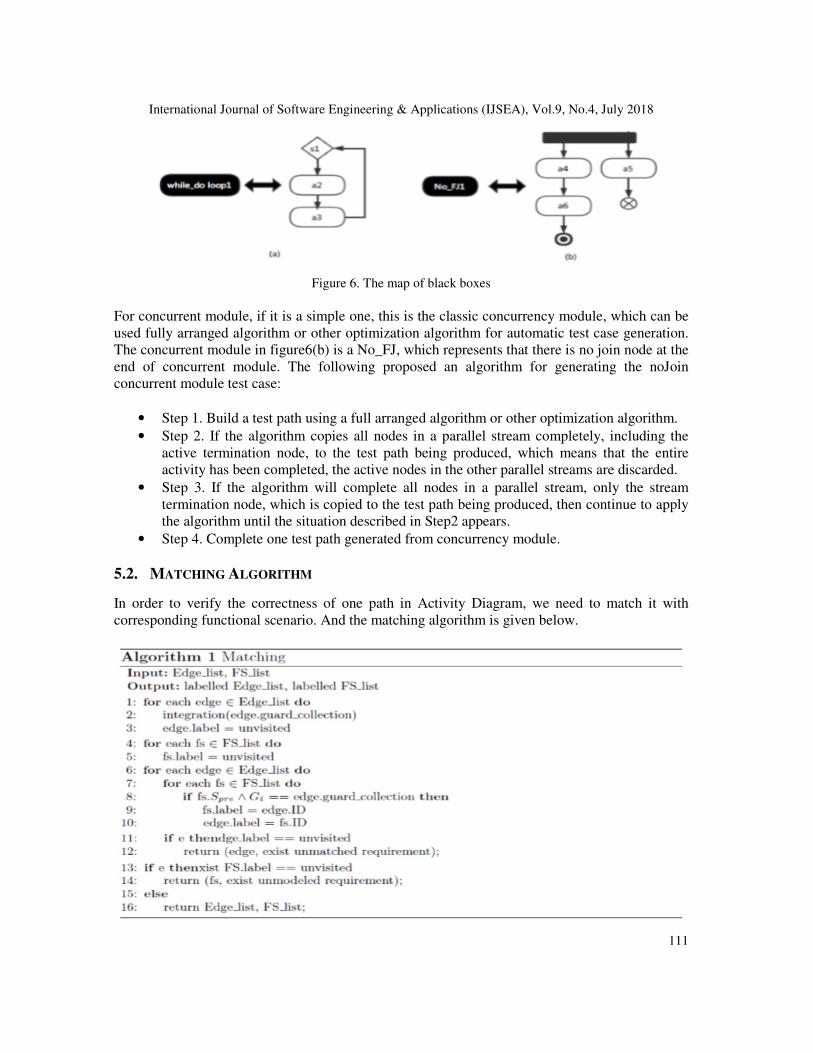
Figure 6. The map of black boxes
For concurrent module, if it is a simple one, this is the classic concurrency module, which can be used fully arranged algorithm or other optimization algorithm for automatic test case generation. The concurrent module in figure6(b) is a No_FJ, which represents that there is no join node at the end of concurrent module. The following proposed an algorithm for generating the noJoin concurrent module test case:
• Step 1. Build a test path using a full arranged algorithm or other optimization algorithm.
• Step 2. If the algorithm copies all nodes in a parallel stream completely, including the active termination node, to the test path being produced, which means that the entire activity has been completed, the active nodes in the other parallel streams are discarded.
• Step 3. If the algorithm will complete all nodes in a parallel stream, only the stream termination node, which is copied to the test path being produced, then continue to apply the algorithm until the situation described in Step2 appears.
• Step 4. Complete one test path generated from concurrency module.
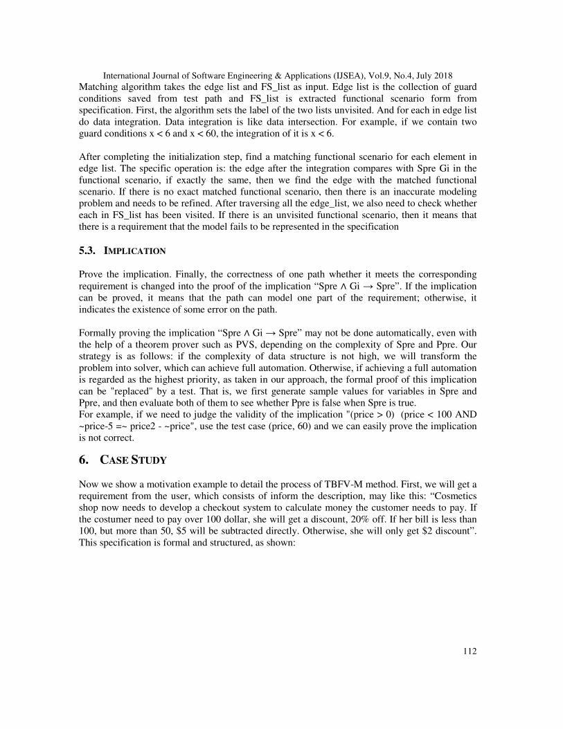
5.2. MATCHING ALGORITHM
In order to verify the correctness of one path in Activity Diagram, we need to match it with corresponding functional scenario. And the matching algorithm is given below.
International Journal of Software Engineering & Applications (IJSEA), Vol.9, No.4, July 2018
112
Matching algorithm takes the edge list and FS_list as input. Edge list is the collection of guard conditions saved from test path and FS_list is extracted functional scenario form from specification. First, the algorithm sets the label of the two lists unvisited. And for each in edge list do data integration. Data integration is like data intersection. For example, if we contain two guard conditions x < 6 and x < 60, the integration of it is x < 6. After completing the initialization step, find a matching functional scenario for each element in edge list. The specific operation is: the edge after the integration compares with Spre Gi in the functional scenario, if exactly the same, then we find the edge with the matched functional scenario. If there is no exact matched functional scenario, then there is an inaccurate modeling problem and needs to be refined. After traversing all the edge_list, we also need to check whether each in FS_list has been visited. If there is an unvisited functional scenario, then it means that there is a requirement that the model fails to be represented in the specification
5.3. IMPLICATION Prove the implication. Finally, the correctness of one path whether it meets the corresponding requirement is changed into the proof of the implication “Spre ∧ Gi → Spre”. If the implication can be proved, it means that the path can model one part of the requirement; otherwise, it indicates the existence of some error on the path. Formally proving the implication “Spre ∧ Gi → Spre” may not be done automatically, even with the help of a theorem prover such as PVS, depending on the complexity of Spre and Ppre. Our strategy is as follows: if the complexity of data structure is not high, we will transform the problem into solver, which can achieve full automation. Otherwise, if achieving a full automation is regarded as the highest priority, as taken in our approach, the formal proof of this implication can be "replaced" by a test. That is, we first generate sample values for variables in Spre and Ppre, and then evaluate both of them to see whether Ppre is false when Spre is true. For example, if we need to judge the validity of the implication "(price > 0) (price < 100 AND ~price-5 =~ price2 - ~price", use the test case (price, 60) and we can easily prove the implication is not correct.
6. CASE STUDY
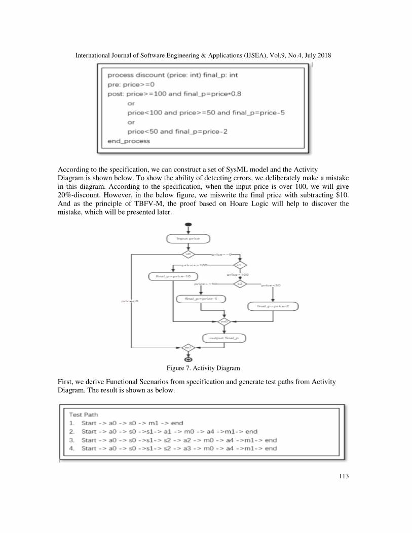
Now we show a motivation example to detail the process of TBFV-M method. First, we will get a requirement from the user, which consists of inform the description, may like this: “Cosmetics shop now needs to develop a checkout system to calculate money the customer needs to pay. If the costumer need to pay over 100 dollar, she will get a discount, 20% off. If her bill is less than 100, but more than 50, $5 will be subtracted directly. Otherwise, she will only get $2 discount”. This specification is formal and structured, as shown:
International Journal of Software Engineering & Applications (IJSEA), Vol.9, No.4, July 2018
113
According to the specification, we can construct a set of SysML model and the Activity Diagram is shown below. To show the ability of detecting errors, we deliberately make a mistake in this diagram. According to the specification, when the input price is over 100, we will give 20%-discount. However, in the below figure, we miswrite the final price with subtracting $10. And as the principle of TBFV-M, the proof based on Hoare Logic will help to discover the mistake, which will be presented later.
Figure 7. Activity Diagram
First, we derive Functional Scenarios from specification and generate test paths from Activity Diagram. The result is shown as below.
International Journal of Software Engineering & Applications (IJSEA), Vol.9, No.4, July 2018
114
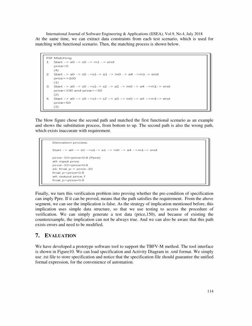
At the same time, we can extract data constraints from each test scenario, which is used for matching with functional scenario. Then, the matching process is shown below.
The blow figure chose the second path and matched the first functional scenario as an example and shows the substitution process, from bottom to up. The second path is also the wrong path, which exists inaccurate with requirement.
Finally, we turn this verification problem into proving whether the pre-condition of specification can imply Ppre. If it can be proved, means that the path satisfies the requirement. From the above segment, we can see the implication is false. As the strategy of implication mentioned before, this implication uses simple data structure, so that we use testing to access the procedure of verification. We can simply generate a test data (price,150), and because of existing the counterexample, the implication can not be always true. And we can also be aware that this path exists errors and need to be modified.
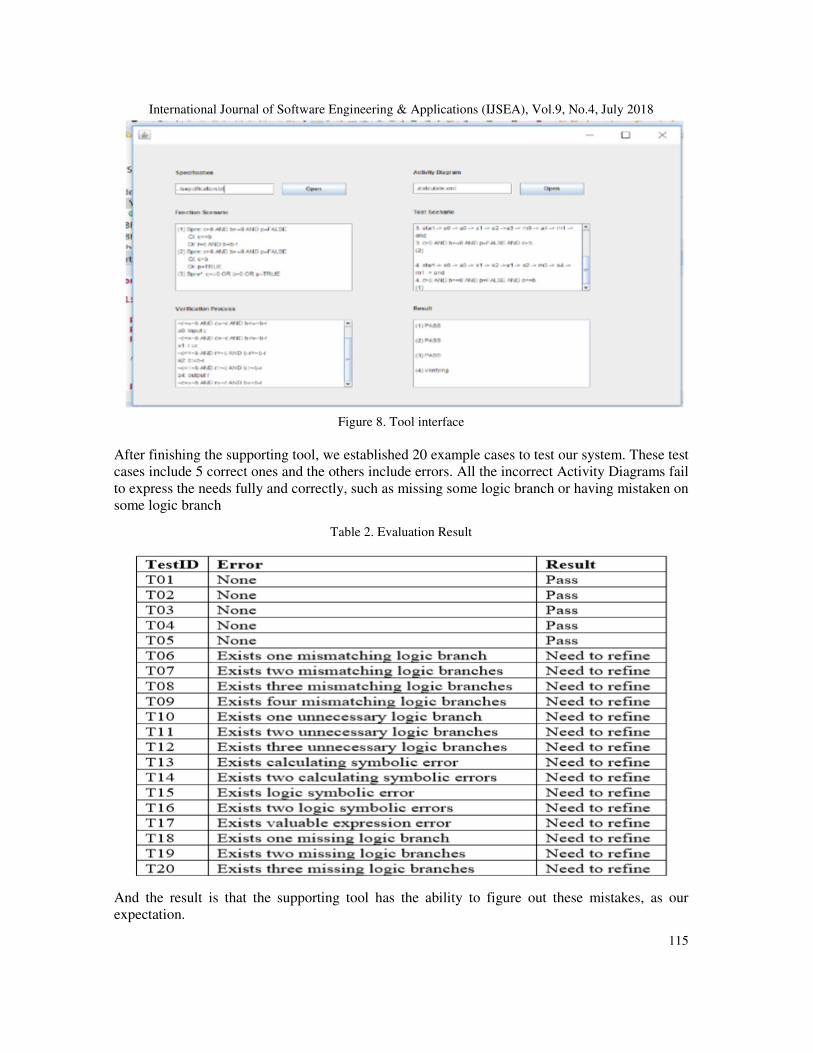
7. EVALUATION We have developed a prototype software tool to support the TBFV-M method. The tool interface is shown in Figure10. We can load specification and Activity Diagram in .xml format. We simply use .txt file to store specification and notice that the specification file should guarantee the unified formal expression, for the convenience of automation.
International Journal of Software Engineering & Applications (IJSEA), Vol.9, No.4, July 2018
115
Figure 8. Tool interface
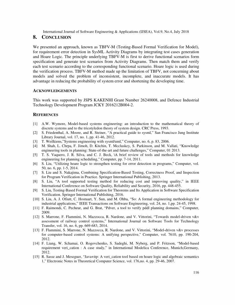
After finishing the supporting tool, we established 20 example cases to test our system. These test cases include 5 correct ones and the others include errors. All the incorrect Activity Diagrams fail to express the needs fully and correctly, such as missing some logic branch or having mistaken on some logic branch
Table 2. Evaluation Result
And the result is that the supporting tool has the ability to figure out these mistakes, as our expectation.
International Journal of Software Engineering & Applications (IJSEA), Vol.9, No.4, July 2018
116
8. CONCLUSION
We presented an approach, known as TBFV-M (Testing-Based Formal Verification for Model), for requirement error detection in SysML Activity Diagrams by integrating test cases generation and Hoare Logic. The principle underlying TBFV-M is first to derive functional scenarios form specification and generate test scenarios from Activity Diagrams. Then match them and verify each test scenario according to the corresponding functional scenario. Hoare logic is used during the verification process. TBFV-M method made up the limitation of TBFV, not concerning about models and solved the problem of inconsistent, incomplete, and inaccurate models. It has advantage in reducing the probability of system error and shortening the developing time.
ACKNOWLEDGEMENTS
This work was supported by JSPS KAKENHI Grant Number 26240008, and Defence Industrial Technology Development Program JCKY 2016212B004-2.
REFERENCES
[1] A.W. Wymore, Model-based systems engineering: an introduction to the mathematical theory of discrete systems and to the tricotyledon theory of system design. CRC Press, 1993.
[2] S. Friedenthal, A. Moore, and R. Steiner, “A practical guide to sysml,” San Francisco Jung Institute Library Journal, vol. 17, no. 1, pp. 41-46, 2012.
[3] T. Weilkiens,”Systems engineering with sysml/uml,” Computer, no. 6, p. 83, 2006. [4] M. Shah, L. Chrpa, F. Jimoh, D. Kitchin, T. Mccluskey, S. Parkinson, and M. Vallati, “Knowledge
engineering tools in planning: State-of-the-art and future challenges,” Computer, 01 2013. [5] T. S. Vaquero, J. R. Silva, and C. J. Beck, \A brief review of tools and methods for knowledge
engineering for planning scheduling," Computer, pp. 7-14, 2011. [6] S. Liu, “Utilizing hoare logic to strengthen testing for error detection in programs,” Computer, vol.
50, no. 6, pp. 1-5, 2014. [7] S. Liu and S. Nakajima, Combining Specification-Based Testing, Correctness Proof, and Inspection
for Program Verification in Practice. Springer International Publishing, 2013. [8] S. Liu, “A tool supported testing method for reducing cost and improving quality,” in IEEE
International Conference on Software Quality, Reliability and Security, 2016, pp. 448-455. [9] S. Liu, Testing-Based Formal Verification for Theorems and Its Application in Software Specification
Verification. Springer International Publishing, 2016. [10] S. Liu, A. J. Ofiutt, C. Hostuart, Y. Sun, and M. Ohba, “So: A formal engineering methodology for
industrial applications,” IEEE Transactions on Software Engineering, vol. 24, no. 1,pp. 24-45, 1998. [11] F. Raimondi, C. Pecheur, and G. Brat, “Pdver, a tool to verify pddl planning domains,” Computer,
2009. [12] S. Marrone, F. Flammini, N. Mazzocca, R. Nardone, and V. Vittorini, “Towards model-driven v&v
assessment of railway control systems,” International Journal on Software Tools for Technology Transfer, vol. 16, no. 6, pp. 669-683, 2014.
[13] F. Flammini, S. Marrone, N. Mazzocca, R. Nardone, and V. Vittorini, “Model-driven v&v processes for computer-based control systems: A unifying perspective," Computer, vol. 7610, pp. 190-204, 2012.
[14] F. Liang, W. Schamai, O. Rogovchenko, S. Sadeghi, M. Nyberg, and P. Fritzson, “Model-based requirement veri_cation : A case study,” in International Modelica Conference, Munich,Germany, 2012.
[15] R. Sasse and J. Meseguer, “Java+itp: A veri_cation tool based on hoare logic and algebraic semantics 1,” Electronic Notes in Theoretical Computer Science, vol. 176,no. 4, pp. 29-46, 2007.
International Journal of Software Engineering & Applications (IJSEA), Vol.9, No.4, July 2018
117
[16] M. O. Myreen and M. J. C. Gordon, “Hoare logic for realistically modelled machine code.” In TOOLS and Algorithms for the Construction and Analysis of Systems, International Conference, Tacas 2007, Held As, 2007, pp. 568-582.
[17] D. Kundu and D. Samanta, “A Novel Approach to Generate Test Cases from UML Activity Diagrams,” Journal of Object Technology, vol. 8, no. 3, pp. 65–83, 2009.
[18] J. Lasalle, F. Peureux, and F. Fondement, “Development of an Automated MBT Toolchain from UML/Sysml Models,” Innovations in Systems Software Engineering, vol. 7, no. 4, pp. 247–256, 2011.
[19] M. Chen, X. Qiu, and X. Li, “Automatic Test Case Generation for UML Activity Diagrams,” in International Workshop on Automation of Software Test, 2006, pp. 2–8.
[20] S. Khurshid and D. Marinov, “Testera: Speci_cation-based testing of java programs using sat, ”Automated Software Engineering, vol. 11, no. 4, pp. 403-434, 2004.
[21] S. Liu and S. Nakajima, “A decompositional approach to automatic test case generation based on formal specifications,” in International Conference on Secure Software Integration Reliability Improvement, 2010, pp. 147-155.
[22] S. Liu, T. Hayashi, K. Takahashi, K. Kimura, T. Nakayama, and S. Nakajima, “Automatic transformation from formal specifications to functional scenario forms for automatic test case generation," in New Trends in Software Methodologies, TOOLS and Techniques Proceedings of the Somet 10, September 29 October 1, 2010, Yokohama City, Japan, 2010, pp. 383-397.
[23] Kent and Stuart, Model Driven Engineering. Springer Berlin Heidelberg, 2002. [24] M. Broy, K. Havelund, R. Kumar, and B. Steffen, Towards a Unified View of Modelling and
Programming (Track Summary). Springer International Publishing, 2016. [25] G. Gay, “Generating effective test suites by combining coverage criteria,” in International
Symposium on Search Based Software Engineering, 2017, pp. 65-82. [26] A. K. Joseph, G. Radhamani, and V. Kallimani, \Improving test efficiency through multiple criteria
coverage-based test case prioritization using modified heuristic algorithm," in International Conference on Computer and Information Sciences, 2016, pp. 430-435.
[27] C. A. R. Hoare, “An axiomatic basis for computer programming,” Communications of the Acm, vol. 12, no. 1, pp. 53-56, 1969.
[28] R. W. Floyd, Assigning Meanings to Programs. Springer Netherlands, 1993. [29] V. R. Pratt, “Semantical consideration on oyo-hoare logic," in Symposium on Foundations of
Computer Science, 1976, pp. 109-121. [30] Y. Yin, Y. Xu, W. Miao, and Y. Chen, \An automated test case generation approach based on activity
diagrams of sysml," International Journal of Performability Engineering, vol. 13, no. 6, pp. 922-936, 2017.
AUTHORS Yufei Yin Master Student of East China Normal University Exchange student in Hosei University
Prof. Dr. Shaoying Liu High-Quality Software Engineering Lab Department Faculty of Computer and Information Sciences Hosei University
Prof. Dr. Yixiang Chen Software and hardware co design technology and application, director of Engineering Research Centre East China Normal University