Embed Size (px)
Citation preview
12th Annual Sucker Rod Pumping
WorkshopRenaissance Hotel
Oklahoma City, Oklahoma
September 27 – 30, 2016
Validating Vertical-Hole Diagnostic Models with Measured Sandia Data
Victoria Pons, Ph.D.
Weatherford
Introduction
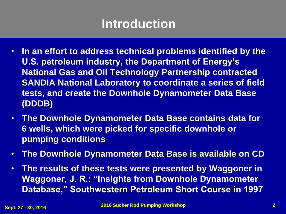
• In an effort to address technical problems identified by the
U.S. petroleum industry, the Department of Energy’s
National Gas and Oil Technology Partnership contracted
SANDIA National Laboratory to coordinate a series of field
tests, and create the Downhole Dynamometer Data Base
(DDDB)
• The Downhole Dynamometer Data Base contains data for
6 wells, which were picked for specific downhole or
pumping conditions
• The Downhole Dynamometer Data Base is available on CD
• The results of these tests were presented by Waggoner in
Waggoner, J. R.: “Insights from Downhole Dynamometer
Database,” Southwestern Petroleum Short Course in 1997
Sept. 27 - 30, 20162016 Sucker Rod Pumping Workshop 2
• In 1986, Glenn Albert developed an electronic downhole dynamometer
• Glenn Albert is the founder of Albert Engineering (Longmont, Colorado)
• The Sandia National Laboratory compiled a series of test data collected with a set of five downhole tools built by Albert Engineering under contract to Sandia National
• The necessary memory tools were deployed in the sucker rod string and equipped with sensors that were capable of measuring pressure, temperature, load and acceleration
• The position was calculated by integrating the acceleration twice, yielding a load versus position downhole dynagraph
Introduction
Sept. 27 - 30, 20162016 Sucker Rod Pumping Workshop 3
Introduction
• Up until the study, it was common practice to rely on load versus position information measured at the surface to infer stresses on the sucker rod string downhole
• Primarily, the motivation behind this research was to try to minimize sucker rod failures, which represent a significant cost to the oil recovery industry
• The downhole dynamometer is a 12-inch-long cylindrical steel probe
• Along each probe's surface is a collection of sensors including strain gauges, an accelerometer, and pressure and temperature gauges
• Several tools are deployed downhole for each well at specific key depths
• All these measurements are taken as the wells are pumping
Sept. 27 - 30, 20162016 Sucker Rod Pumping Workshop 4
Wave Equation Solution vs. SANDIA
• The Downhole Dynamometer Data Base contains data for 6
wells, which were picked for specific downhole or pumping
conditions
• Results from the current Modified-Everitt-Jennings algorithm
and from the Gibb’s method are compared to actual
dynamometer readings from SANDIA data
• The Modified Everitt-Jennings uses finite differences to solve
the wave equation while the Gibb’s method uses Fourier
Series and separation of variables
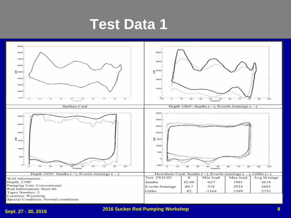
• For each well, the surface card is displayed as well as the MEJ
calculated card (solid), the Gibb’s card (dashed) and SANDIA
measured downhole card (dotted)
Sept. 27 - 30, 20162016 Sucker Rod Pumping Workshop 5
Test Data 1
• This well has a depth of 2700 ft. with a 0.75 in. API Grade
'C' steel rod string and a 1.5 in. RWA pump in 2.875 in.
tubing.
• The pumping speed is 11 SPM with a 86 in. surface stroke.
• The dynamometer tools were installed in the rod string as
follows:
1) below the pump
2) above the pump at 2708 ft.
3) at 2456 ft.
4) at 1004 ft.
5) at 2 ft.
Sept. 27 - 30, 20162016 Sucker Rod Pumping Workshop 6
Test Data 1
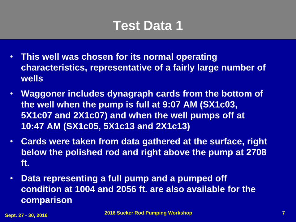
• This well was chosen for its normal operating
characteristics, representative of a fairly large number of
wells
• Waggoner includes dynagraph cards from the bottom of
the well when the pump is full at 9:07 AM (SX1c03,
5X1c07 and 2X1c07) and when the well pumps off at
10:47 AM (SX1c05, 5X1c13 and 2X1c13)
• Cards were taken from data gathered at the surface, right
below the polished rod and right above the pump at 2708
ft.
• Data representing a full pump and a pumped off
condition at 1004 and 2056 ft. are also available for the
comparison
Sept. 27 - 30, 20162016 Sucker Rod Pumping Workshop 7
Test Data 1
Sept. 27 - 30, 20162016 Sucker Rod Pumping Workshop 8
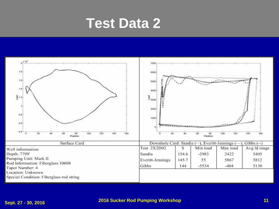
Test Data 2
• This well has a depth of 7600 ft. with a mixed fiberglass and steel
• The rod string composition is:
– 4408 ft. of 1.125 in. Norris fiberglass rods
– 3200 ft. of 1 in. API Grade ‘D’ steel rods
– 1.5 in. insert pump in 2.875 in. tubing
• The dynamometer tools were installed in the rod string as
follows:
1) below the pump
2) above the pump at 7616 ft.
3) 75 ft. above the pump in the 1 in. rods at 7539 ft.
4) at the fiberglass/steel crossover at 4412 ft.
5) 75 ft. above the crossover at 4335 ft.
Sept. 27 - 30, 20162016 Sucker Rod Pumping Workshop 9
Test Data 2
• Well production at 8.2 SPM with a 144 in. surface
stroke:
– 29 BOPD, API = 40
– 210 BWPD
• GOR = 1620
• Because the tubing anchor was set at 6168 ft. and the
seating nipple at 7655 ft., 1487 ft. of tubing below the
anchor was subject to stretch
• The rods parted in the shallow section of the well,
terminating the test after one downhole test period
and corresponding surface measurement
Sept. 27 - 30, 20162016 Sucker Rod Pumping Workshop 10
Test Data 2
Sept. 27 - 30, 20162016 Sucker Rod Pumping Workshop 11
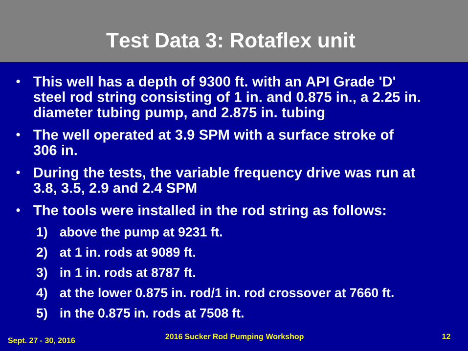
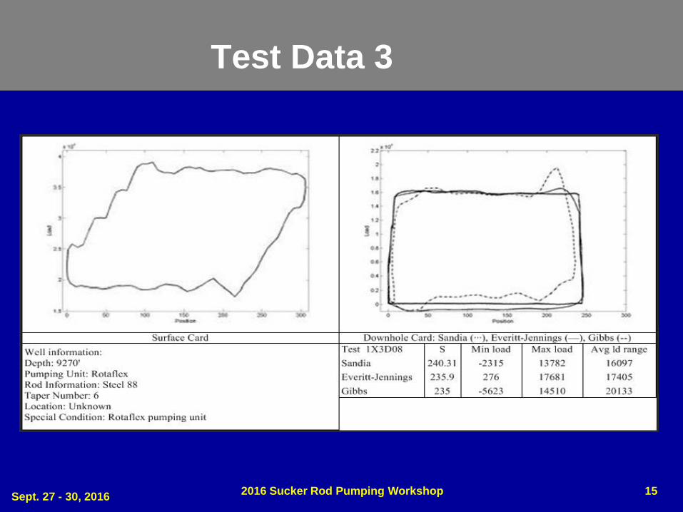
Test Data 3: Rotaflex unit
• This well has a depth of 9300 ft. with an API Grade 'D' steel rod string consisting of 1 in. and 0.875 in., a 2.25 in. diameter tubing pump, and 2.875 in. tubing
• The well operated at 3.9 SPM with a surface stroke of 306 in.
• During the tests, the variable frequency drive was run at 3.8, 3.5, 2.9 and 2.4 SPM
• The tools were installed in the rod string as follows:
1) above the pump at 9231 ft.
2) at 1 in. rods at 9089 ft.
3) in 1 in. rods at 8787 ft.
4) at the lower 0.875 in. rod/1 in. rod crossover at 7660 ft.
5) in the 0.875 in. rods at 7508 ft.
Sept. 27 - 30, 20162016 Sucker Rod Pumping Workshop 12
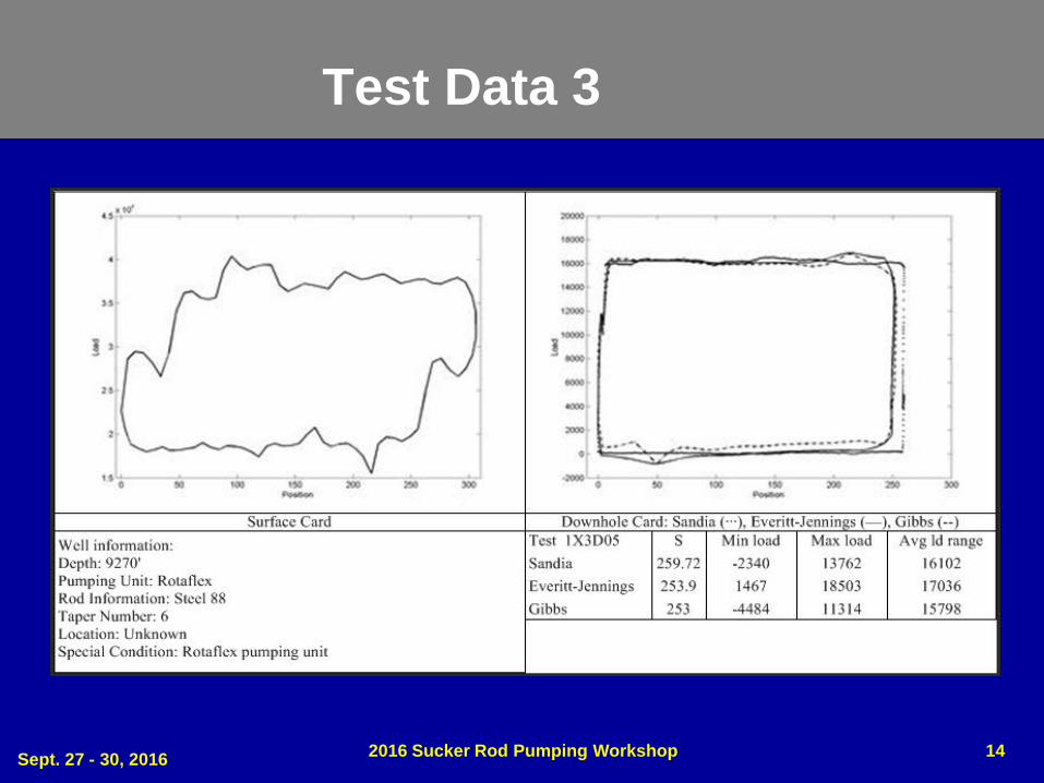
Test Data 3
• This well was chosen in an effort to observe the
dynamics of the Rotaflex pumping unit at different
pumping speeds and the dynamics of the rod string
affected by the rapid direction changes during operation
• Waggoner observed that the loads and shape of the
cards were similar
• Waggoner also observed that the downhole stroke length
was about 5% longer at the faster pumping speed
Sept. 27 - 30, 20162016 Sucker Rod Pumping Workshop 13
Test Data 3
Sept. 27 - 30, 20162016 Sucker Rod Pumping Workshop 14
Test Data 3
Sept. 27 - 30, 20162016 Sucker Rod Pumping Workshop 15
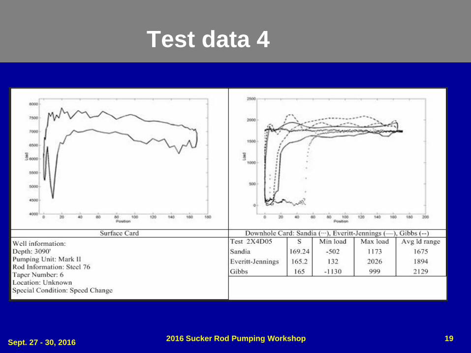
Test data 4
• This well has a depth of 3100 ft. with an API Grade 'D' steel
rod string consisting of 0.875 in. and 0.75 in. rods, with
1.25 in. sinker bars, a 1.25 in. insert pump and 2.875 in.
tubing
• Tests were conducted using pump speed of 8.8, 6.7 and
4.6 SPM with a surface stroke of 168 in.
• The tools were installed in the rod string as follows:
1) below the pump
2) above the pump at 3010 ft.
3) at the sinker bar/0.75 in. rod crossover at 2708 ft.
4) at the 0.75 in. rod/0.875 in. rod crossover at 1006 ft.
5) below the polished rod at 7508 ft.
Sept. 27 - 30, 20162016 Sucker Rod Pumping Workshop 16
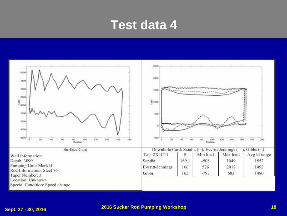
Test data 4
• This well was chosen to explore the effects of both
different pumping speeds and varying pump fillages on
the dynamics of the sucker rod string
• Waggoner observed that the dynagraph data at the
slower speed yields more regular downhole cards
• Waggoner also remarked that the downhole tools and the
surface tools were not synchronized to record data at the
same time
• The effect of this was that the strokes during this interval
were not consistent. It was observed that even though
the surface card showed about 15% pump fillage, the
downhole cards at Tool #2 and Tool #1 showed pump
fillages of 30% and 50%, respectively
Sept. 27 - 30, 20162016 Sucker Rod Pumping Workshop 17
Test data 4
Sept. 27 - 30, 20162016 Sucker Rod Pumping Workshop 18
Test data 4
Sept. 27 - 30, 20162016 Sucker Rod Pumping Workshop 19
Conclusions
• Even though the objective of the SANDIA testing was to
reduce failures in reciprocating rod lift, it provided a way to
prove the effectiveness of the wave equation solution
• Solving the wave equation with appropriate damping
provides an accurate and reliable way to compute
downhole cards
• For the above results, the damping had to be adjusted
manually since the required inputs for the iteration on
damping were not available
• The data collected for the Sandia experiment only
represents vertical wells. What about deviated wells?
Sept. 27 - 30, 20162016 Sucker Rod Pumping Workshop 20

Vertical vs. Deviated
Sept. 27 - 30, 20162016 Sucker Rod Pumping Workshop 21
???
DeviatedVertical
QUESTIONS?
Sept. 27 - 30, 20162016 Sucker Rod Pumping Workshop 22
Copyright
Rights to this presentation are owned by the company(ies) and/or author(s) listed on the title page. By submitting this presentation to the Sucker Rod Pumping Workshop, they grant to the Workshop, the Artificial Lift Research and Development Council (ALRDC), and the Southwestern Petroleum Short Course (SWPSC), rights to:
– Display the presentation at the Workshop.
– Place it on the www.alrdc.com web site, with access to the site to be as directed by the Workshop Steering Committee.
– Place it on a CD for distribution and/or sale as directed by the Workshop Steering Committee.
Other use of this presentation is prohibited without the expressed written permission of the author(s). The owner company(ies) and/or author(s) may publish this material in other journals or magazines if they refer to the Sucker Rod Pumping Workshop where it was first presented.
Sept. 27 - 30, 20162016 Sucker Rod Pumping Workshop 23
Disclaimer
The following disclaimer shall be included as the last page of a Technical Presentation or Continuing Education Course. A similar disclaimer is included on the front page of the Sucker Rod Pumping Web Site.
The Artificial Lift Research and Development Council and its officers and trustees, and the Sucker Rod Pumping Workshop Steering Committee members, and their supporting organizations and companies (here-in-after referred to as the Sponsoring Organizations), and the author(s) of this Technical Presentation or Continuing Education Training Course and their company(ies), provide this presentation and/or training material at the Sucker Rod Pumping Workshop "as is" without any warranty of any kind, express or implied, as to the accuracy of the information or the products or services referred to by any presenter (in so far as such warranties may be excluded under any relevant law) and these members and their companies will not be liable for unlawful actions and any losses or damage that may result from use of any presentation as a consequence of any inaccuracies in, or any omission from, the information which therein may be contained.
The views, opinions, and conclusions expressed in these presentations and/or training materials are those of the author and not necessarily those of the Sponsoring Organizations. The author is solely responsible for the content of the materials.
The Sponsoring Organizations cannot and do not warrant the accuracy of these documents beyond the source documents, although we do make every attempt to work from authoritative sources. The Sponsoring Organizations provide these presentations and/or training materials as a service. The Sponsoring Organizations make no representations or warranties, express or implied, with respect to the presentations and/or training materials, or any part thereof, including any warrantees of title, non-infringement of copyright or patent rights of others, merchantability, or fitness or suitability for any purpose.
Sept. 27 - 30, 20162016 Sucker Rod Pumping Workshop 24