Embed Size (px)
Citation preview
“Validating the Laser Welding Process, A Case Study”
David W. Steinmeier - microJoining Solutions &
Lisa Schaller – HealthTronics, Inc. ©2015
Page 1 of 14
Introduction
The laser welding world encompasses a wide range of applications and part sizes. Within this
unique world, competition for securing new orders and retaining existing business is always
increasing. One way to provide a competitive edge is to validate your laser welding process.
The automotive and medical device sectors have a long history of using the validation process.
To ensure consistent laser weld quality, the automotive companies require proof of laser welding
validation from their automotive sub-system suppliers. In addition, the Federal Food and Drug
Administration (FDA) requires medical device manufacturers to validate processes used to
manufacture a medical device. Both sectors essentially employ the same validation process, but
use different labels for each validation component.
This article illustrates the necessary steps and highlight considerations to successfully validate
the laser weld process.
Validation and Verification Definitions
The terms validation and verification are often used interchangeably, but have very different
meanings. Validation ensures that the right product was made. Verification ensures that the
product was made right. FDA 21CFR820.3 provides the following detailed definitions:
Validation means confirmation by examination and provision of objective evidence that the
particular requirements for a specific intended use can be consistently fullfilled1.
Verification means confirmation by examination and provision of objective evidence that the
specified requirements have been fulfilled2.
Process Validation means establishing by objective evidence that a process consistently
produces a result or product meeting its predetermined specifications3.
Why Validate?
There are four major reasons for validating the welding process:
One, for Six-Sigma oriented manufacturers, there is no laser weld monitor or checker on the
market today that can separate bad welds from good welds to a six-sigma confidence level. The
only known means of determining weld quality without destroying 100% of the finished product
is to validate the laser welding process.
Two, for medical device manufacturers, the FDA mandates that manufacturing processes that
cannot be fully verified must be validated as part of the company’s Quality System Regulation
(QSR)4.

“Validating the Laser Welding Process, A Case Study”
David W. Steinmeier - microJoining Solutions &
Lisa Schaller – HealthTronics, Inc. ©2015
Page 2 of 14
Three, the improvement to process yield through the reduction of product scrap and field failures
far outweighs the cost of validating the laser welding process.
Four, validation is a good marketing tool. Manufacturers capable of proving their laser weld
quality level to their customers have a substantial advantage over their competition.
Validation Components
The validation process consists of six main components, beginning with the Validation Plan(VP)
and ending with the Product Performance Qualification (PPQ). See Figure-1. Each component
contains its own protocol, data, and reporting documents. Manufacturers may implement these
six steps in different ways to accommodate their own unique design and manufacturing
processes. A common modification incorporates the Equipment Installation Qualification (IQ)
with the Equipment Operational Qualification (OQ). Another variation includes the Design of
Experiment (DoE) process as part of the Equipment Operational Qualification (OQ) instead of
the more traditional method of incorporating the DoE into the Process Qualification (PQ). In
either case, the goal is the same; to consistently produce a product that meets the intended
product use.
Validation Plan (VP)
Equipment Installation
Qualification (IQ)
Equipment Operational Qualification
(OQ)
Process Qualification
(PQ)
Process Validation
(PV)
Product Performance Qualification
(PPQ)
Figure 1 – Validation Components
“Validating the Laser Welding Process, A Case Study”
David W. Steinmeier - microJoining Solutions &
Lisa Schaller – HealthTronics, Inc. ©2015
Page 3 of 14
Laser Welding Validation Example
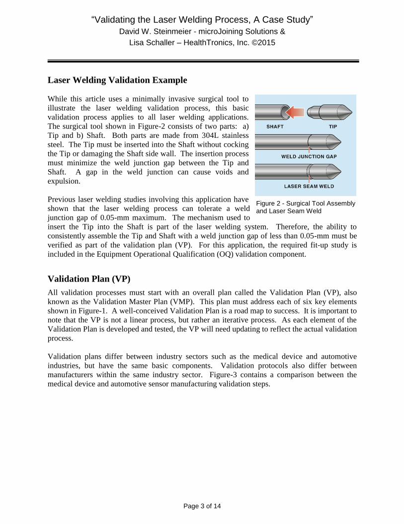
While this article uses a minimally invasive surgical tool to
illustrate the laser welding validation process, this basic
validation process applies to all laser welding applications.
The surgical tool shown in Figure-2 consists of two parts: a)
Tip and b) Shaft. Both parts are made from 304L stainless
steel. The Tip must be inserted into the Shaft without cocking
the Tip or damaging the Shaft side wall. The insertion process
must minimize the weld junction gap between the Tip and
Shaft. A gap in the weld junction can cause voids and
expulsion.
Previous laser welding studies involving this application have
shown that the laser welding process can tolerate a weld
junction gap of 0.05-mm maximum. The mechanism used to
insert the Tip into the Shaft is part of the laser welding system. Therefore, the ability to
consistently assemble the Tip and Shaft with a weld junction gap of less than 0.05-mm must be
verified as part of the validation plan (VP). For this application, the required fit-up study is
included in the Equipment Operational Qualification (OQ) validation component.
Validation Plan (VP)
All validation processes must start with an overall plan called the Validation Plan (VP), also
known as the Validation Master Plan (VMP). This plan must address each of six key elements
shown in Figure-1. A well-conceived Validation Plan is a road map to success. It is important to
note that the VP is not a linear process, but rather an iterative process. As each element of the
Validation Plan is developed and tested, the VP will need updating to reflect the actual validation
process.
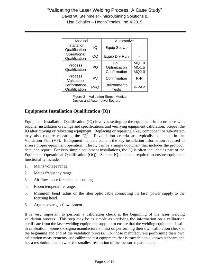
Validation plans differ between industry sectors such as the medical device and automotive
industries, but have the same basic components. Validation protocols also differ between
manufacturers within the same industry sector. Figure-3 contains a comparison between the
medical device and automotive sensor manufacturing validation steps.
Figure 2 - Surgical Tool Assembly and Laser Seam Weld
“Validating the Laser Welding Process, A Case Study”
David W. Steinmeier - microJoining Solutions &
Lisa Schaller – HealthTronics, Inc. ©2015
Page 4 of 14
Medical Automotive
Installation Qualification
IQ Equip Set Up -
Operational Qualification
OQ Equip Dry Run -
Process Qualification
PQ DoE
Optimization Confirmation
MQ1.0 MQ1.5 MQ2.0
Process Validation
PV Confirmation R-R
Performance Qualification
PPQ Environmental
Tests P-PAP
Equipment Installation Qualification (IQ)
Equipment Installation Qualification (IQ) involves setting up the equipment in accordance with
supplier installation drawings and specifications and verifying equipment calibration. Repeat the
IQ after moving or relocating equipment. Replacing or repairing a key component or sub-system
may also require repeating the IQ5. Revalidation criteria are typically contained in the
Validation Plan (VP). Equipment manuals contain the key installation information required to
ensure proper equipment operation. The IQ can be a single document that includes the protocol,
data, and report. For very simple equipment installations, the IQ is often included as part of the
Equipment Operational Qualification (OQ). Sample IQ elements required to ensure equipment
functionality include:
1. Mains voltage range.
2. Mains frequency range.
3. Air flow space for adequate cooling.
4. Room temperature range.
5. Minimum bend radius on the fiber optic cable connecting the laser power supply to the
focusing head.
6. Argon cover gas flow system.
It is very important to perform a calibration check at the beginning of the laser welding
validation process. This step may be as simple as verifying the information on a calibration
certificate from the laser welding equipment supplier to ensure that the welding equipment is still
in calibration. Some six-sigma manufacturers insist on performing their own calibration check at
the beginning and end of the validation process. For those manufacturers performing their own
calibration measurements, use calibrated test equipment that is traceable to a known standard and
has a resolution that is twice the smallest resolution of the measured parameter.
Figure 3 – Validation Steps, Medical Device and Automotive Sectors

“Validating the Laser Welding Process, A Case Study”
David W. Steinmeier - microJoining Solutions &
Lisa Schaller – HealthTronics, Inc. ©2015
Page 5 of 14
Equipment Operational Qualification (OQ)
Equipment Operational Qualification (OQ) verifies that the laser welding system meets the
manufacturer’s performance specifications. The OQ also establishes procedures and record
keeping for equipment calibration, cleaning, operation, maintenance, and operator training.
Equipment manuals contain the key specifications regarding equipment capability. Repeat the
OQ after moving or relocating equipment. Replacing or repairing a key component or sub-
system may also require repeating the OQ5. Revalidation criteria are typically contained in the
Validation Plan (VP).
For laser welding systems, the most important welding equipment parameters are weld power,
pulse duration, spot size, pulse repetition frequency, which controls weld spot overlap, and weld
spot location in all 3-Axes of the laser welding system. Verify that the entire welding system
produces the programmed laser welding parameter power over the projected operating ranges on
a repeatable basis and append the data to the OQ report. In the automotive sensor industry, the
OQ may also involve operating an automatic welding station without weld energy or parts for a
24-hour “dry run”.
Many laser welds are very sensitive to the weld junction gap (fit-up) and the weld spot location
on the weld junction in all three axes, X, Y, and Z. The laser weld shown in Figure-2 is no
exception. Therefore, Gage R&R studies must be conducted on the laser welding system to
establish capability for both the weld junction fit-up and weld spot position. Use three operators
to conduct the Gage R&R studies. For the surgical tool example shown in Figure-2, the
maximum range data from all three operators were compared against the maximum range limit
values. If available, use historical data from similar laser welding processes to set limits. If
historical data is not available, then determine limit values using the Design of Experiment
(DoE) process. For this example, the maximum range limits for both the weld junction gap and
weld spot location were derived from historical data.
Gage R&R Study Results – Weld Junction Fit-up
Maximum Range Limit Value= 0.050-mm
Actual Weld Junction Fit-up (Gap) Range = 0.025-mm < 0.05-mm, passed
Gage R&R Study Results – Weld Spot Location, worst case range value
Maximum Range Limit Value = 0.30-mm
Actual X-Axis (Shaft Axis) Range = 0.09-mm < 0.30-mm, passed
Actual Y-Axis (Shaft Diameter) Range = 0.06-mm < 0.30-mm, passed
Actual Z-Axis (Laser Focus) = 0.09-mm < 0.30-mm, passed
For the surgical tool example, both Gage R&R studies successfully established the fit-up and
laser weld spot positioning capability.

“Validating the Laser Welding Process, A Case Study”
David W. Steinmeier - microJoining Solutions &
Lisa Schaller – HealthTronics, Inc. ©2015
Page 6 of 14
Process Qualification (PQ)
The Process Qualification (PQ) follows the OQ and contains seven sub-components as shown in
Figure-4.
Select the PQ Weld Quality Metrics
PQ begins with selecting the weld quality metrics, which should represent the stresses and
physical limitations subjected on the final laser welded product by the end user. This surgical
tool is pressurized during the procedure and must be free of voids, even if the voids do not leak.
For this example, two PQ weld quality metrics were selected: a) minimum burst pressure and b)
absence of voids.
Measuring burst pressure is time consuming, expensive, and destructive. Therefore, it was
decided to add two non-destructive metrics that might correlate with the burst pressure: a) weld
spot location in relation to the weld junction centerline and b) weld width.
Conduct the Pre-DoE Study
The purpose of conducting a pre-Design of Experiment (DoE) study is to:
1. Select the variable input factors.
2. Fix certain input factors.
3. Identify input factors which represent experimental “noise”.
4. Determine the range for each variable input factor.
Select PQ Weld Quality Metrics
Conduct Pre-DoE Study
Conduct DoE
Determine Lot Run & Sample
Size
Conduct Confirmation
Run
Apply PQ Acceptance
Criteria
Optimize Welding
Parameters
Figure 4 - PQ Components

“Validating the Laser Welding Process, A Case Study”
David W. Steinmeier - microJoining Solutions &
Lisa Schaller – HealthTronics, Inc. ©2015
Page 7 of 14
Select Variable Input Factors
To determine which input factors to include as variable input factors in the DoE, examine
existing laser welding production processes. For this example, the following variable input
factors were selected:
1. Peak power
2. Pulse duration or pulse width
3. % Weld spot overlap
4. Weld spot location in relation to the weld junction
Select Fixed Input Factors
Next select what input factors to fix or hold constant. Note that Tip/Shaft Assembly rotational
speed and the frequency or pulse repetition rate control the % weld spot overlap. The easiest
parameter to vary is the pulse repetition frequency. Therefore, fix the Tip/Shaft Assembly
rotational speed. The table in Figure-5 represents the fixed input factors.
Parameter Value
Mode Single Pulse
Pulse Shape Square
Weld Spot Diameter 0.46 to 0.50-mm
Spot Focal Point Part Surface
Rotational Speed 9.0-RPM
Laser Beam Angle Perpendicular to Part Surface
Cover Gas Argon
Cover Gas Flow 30 to 35 CFH
Cover Gas Nozzle Part of Focusing Head
Noise Factor Identification
Uncontrolled input factors, which represent experimental “noise”, include variations in the weld
junction gap and the weld spot location in relation to the weld junction. The measured limits of
both noise sources are listed in the OQ section.
Variable Input Factor Range
The experimenter must know which variable input factors are important in producing the desired
output responses. A common misconception regarding DoE’s is that the DoE should produce
only perfect welds. A DoE study that produces only perfect welds does not tell the experimenter
how the variable input factors affect the output responses.
Figure 5 – Fixed Input Factors

“Validating the Laser Welding Process, A Case Study”
David W. Steinmeier - microJoining Solutions &
Lisa Schaller – HealthTronics, Inc. ©2015
Page 8 of 14
Therefore, the experimenter must conduct a series of trial and error “mini” experiments to
determine the range for each variable input factor that produces both “cold” and “hot” welds.
Visibly, “cold” laser welds produce voids or incomplete weld flow around the Shaft
circumference, and “hot” laser welds produce unacceptable weld splash and distortions in the
weld flow around the Shaft circumference. Using these definitions for “cold” and “hot” laser
welds resulted in the following variable input factor ranges for the surgical tool example shown
in Figure-2. See the table in Figure-6. Note that Overlap is really one variable where the pulse
repetition frequency (Hz) controls the Overlap %.
Parameter Cold Nominal Hot
Power (watts) 106 113 120
Pulse Duration (ms) 6.0 7.0 8.0
Location (mm) -0.15 0.00 +0.15
Overlap (%) 80 85 90
Overlap (Hz) 11 16 21
Conduct the DoE
A D-Optimal model with 4-variable input factors, 6-replicates, and 3-output responses was used.
The D-Optimal model provides 2-order interactions with excellent model strength and requires
less parts compared to using a full factorial model. The 3-ouput responses included: a) burst
pressure, b) weld width and c) void length.
Figure-7 presents the ANOVA Table for the 3-output responses. The burst pressure and weld
width model results are very strong, with Error values of 13.77% and 11.21% respectively.
Weld spot location is the primary input factor affecting the burst pressure while pulse duration in
the primary input factor affecting the weld width. With an Error value of 84.56%, the void
length model is meaningless. Correlation studies showed no correlation between the weld width
and the burst pressure. Therefore, weld width and void length can’t be used as non-destructive
PQ weld quality metrics.
Burst Weld Void
Source Pressure Width Length
% Contribution % Contribution % Contribution
Power (A) 12.31% 20.16% 7.32%
Pulse (B) 6.17% 44.81% 3.00%
Location (C) 53.95% 2.92% 3.97%
Overlap (D) 13.81% 20.90% 1.15%
Error 13.77% 11.21% 84.56%
Figure 6 – Variable Input Factor Range
Figure 7 – DoE ANOVA Results

“Validating the Laser Welding Process, A Case Study”
David W. Steinmeier - microJoining Solutions &
Lisa Schaller – HealthTronics, Inc. ©2015
Page 9 of 14
Optimize the Welding Parameters
The surgical tool shown in Figure-2 is typically pressurized during Product Performance
Qualification (PPQ) to 20.68-MPa (3.0-ksi). The product design team specified an optimized
target goal of 96.53-MPa (14-ksi) and no voids. The Marginal Means graph for burst pressure
shows that achieving the optimized value is possible. See Figure-8.
Using DoE expert prediction software produces the following optimized set of laser welding
parameters for the surgical tool. See Figure-9.
Parameter Nominal Allowable
Range
Power (watts) 117 +3, -2
Pulse Duration (ms) 7.0 ±0.1
Location (mm) 0.00 ±0.015
Overlap (°) 90 ±1.0
Overlap (Hz) 21 ±0.0
Figure 8 – Marginal Means Graph for Burst Pressure
Figure 9 – Optimized Laser Welding Parameters

“Validating the Laser Welding Process, A Case Study”
David W. Steinmeier - microJoining Solutions &
Lisa Schaller – HealthTronics, Inc. ©2015
Page 10 of 14
Determine the Lot Run and Sample Size
Recall that the most significant input factor controlling the burst pressure is the location of the
weld flow pattern (width) from the weld junction. Therefore, the PQ acceptance metric will use
the weld spot location deviation for qualifying the laser welding process. To prepare for the PQ
Confirmation Run, determine the Lot Run and Sample Size. Use Statistical software such as
Minitab® to calculate the sample size and acceptance criteria. The acceptance testing can use Z-
Test statistics or a minimum Cpk value. The acceptance criteria for a Z-Test is called the “K-
value”.
Confirmation Run Sample Size and K-Value Calculate6 ,7, 8, 9
1. Data is variable data.
2. Production lot run size is normally 2,000 pieces.
3. AQL is 0.023% (5-Sigma = Cpk=1.67).
4. RQL is 0.15% (5-Sigma = Cpk=1.67).
5. Lower limit based on the maximum deviation of the weld flow pattern from the nominal
weld junction that will absolutely prevent weld voids is -0.10-mm.
6. Upper limit based on the maximum deviation of the weld flow pattern from the nominal
weld junction that will absolutely prevent weld voids is +0.10-mm.
7. Historical standard deviation, as estimated from optical measurements of the maximum
range of the weld flow pattern from the nominal weld junction is 0.015-mm.
8. Using 1 through 7, Minitab-15® calculates a minimum sample size of (30) welded pieces
for each operator and an acceptance K-value of 3.2.
Conduct the Confirmation Run
Use three operators to make 30-samples each, for a total of 90-samples using the test conditions
defined in Figure-10 and the fixed parameters listed in Figure-5. The Confirmation Run is
conducted at two different power levels to test the use of a wide weld window during production.
Note: “X” represents the operator identification code.
Weld Number
Laser Power
(W)
Pulse Duration
(ms)
Overlap (%)
Weld Spot
Location (mm)
X-01 to X-15 115 7.0 90 0.00
X-16 to X-30 120 7.0 90 0.00
Figure 10 – PQ Challenge Laser Welding Parameters

“Validating the Laser Welding Process, A Case Study”
David W. Steinmeier - microJoining Solutions &
Lisa Schaller – HealthTronics, Inc. ©2015
Page 11 of 14
Before removing each laser welded sample from
the laser welding system, measure and record the
weld spot location deviation from the weld
junction using the following measurements as
shown in Figure-11.
1. Measure and record D1.
2. Measure and record D2.
3. Calculate and record Weld Width, D3 = D1
+ D2 (ignore the minus sign on D2).
4. Calculate and record Weld Location Error,
D4 = D1 – (D3/2).
5. Use D4 for determining PQ acceptance or
rejection.
6. After measuring the weld spot location for each sample, submit the samples for Process
Validation (PV) testing.
Apply the PQ Acceptance Criteria
Calculate the average and standard deviation of the weld spot location using the 30-sample PQ
data from each operator. Next, calculate the Z-Test statistics, Z.LSL and Z.USL for each
operator using the following formulas:
1. Z.LSL = [(Average weld location error) + (0.10-mm)] / Standard Deviation
2. Z.USL = [(0.10-mm) – (Average weld location error)] / Standard Deviation
The table in Figure-12 shows the Calculated Z.LSL and Calculated Z.USL for each operator.
Welding Operator
Calculated Z.LSL
Min Z.LSL Value
Z.LSL Pass/No
Pass
Calculated Z.USL
Min Z.USL Value
Z.USL Pass/No
Pass
A 10.50 3.2 Pass 10.46 3.2 Pass
B 17.47 3.2 Pass 16.90 3.2 Pass
C 12.50 3.2 Pass 11.32 3.2 Pass
All three operators successfully laser welded Tip/Shaft Assemblies that passed the PQ
acceptance criteria for the weld spot location and contained no voids. The worst case weld spot
location error across all three operators was ±0.025-mm. This value is four times less than the
upper/lower limit range of ±0.10-mm. Thus, the laser welding process is “qualified”, but still
requires process validation testing.
Figure 112 – Z-Test Results, PQ Confirmation Run
Figure 11 – Weld Location Measurement

“Validating the Laser Welding Process, A Case Study”
David W. Steinmeier - microJoining Solutions &
Lisa Schaller – HealthTronics, Inc. ©2015
Page 12 of 14
Process Validation (PV)
Process Validation (PV) establishes that the welding process consistently produces a part or
product meeting its predetermined specification. PV metrics must represent the stresses
encountered during product usage. PV metrics must also be different from the PQ metrics.
Process validation involves correlating the PQ data with the PV data.
For the surgical tool example shown in Figure-2, the first PV weld quality metric is a leak test
using helium gas. The entire surgical tool must not leak at a test pressure of 6.89-MPa (1.0-ksi)
over a 20-second test period. There can be no helium gas bubbles surrounding or emanating
from the laser weld.
The second PV weld quality metric is an outer diameter (OD) test across the entire surgical tool
shaft length. The OD must range between 2.36 to 2.45-mm in order to fit into a guiding tool and
not be too loose. A laser weld does not have a flat surface. The OD across the laser spot weld
width can vary, depending on the laser power and duration. All 90 PQ Confirmation samples
submitted for PV testing passed both PV weld quality tests.
21 CFR Part 820.75 (b)(2) simply states that monitoring and control methods must be
determined10
. To ensure that weld spot location is properly controlled, the worst case weld spot
location deviation from the weld junction measurement obtained within a single lot must be
recorded on the lot traveler. The limit for the weld spot location from the weld junction is
±0.095-mm in order to ensure that the actual Z.LSL and Z.USL values remain above the critical
K-value of 3.2.
Product Performance Qualification (PPQ)
PPQ establishes with documented evidence that the finished product meets all requirements for
functionality and safety. PPQ incorporates a series of environmental tests used to simulate the
operating environment of the finished product. PPQ environmental tests include, but are not
limited to: life cycling, temperature, vibration, humidity, impact, and shipping. Assuming that
no failures of any type occur, the product is considered to be validated. Should weld failures
occur during PPQ, the basic product design for weldability must be re-visited and the laser weld
re-validated.
The surgical environment is well controlled in terms of temperature and humidity. The only
impact and vibration stresses come from the shipping process, which must pass the appropriate
DOT specifications.
For the surgical tool example shown in Figure-2, the first PPQ product metric is a pressure test
using argon gas. The entire surgical tool must not leak at an operating pressure of 20.68-MPa
(3.0-ksi) during the duration of the surgery. There can be no argon gas escaping from any part of
the entire surgical tool assembly.

“Validating the Laser Welding Process, A Case Study”
David W. Steinmeier - microJoining Solutions &
Lisa Schaller – HealthTronics, Inc. ©2015
Page 13 of 14
The second PPQ product metric is a tip temperature test. The tip temperature must remain at
-80°C or lower during the surgical procedure. All 90 PQ Confirmation samples submitted for
PPQ testing passed both PPQ product tests.
Conclusion
Laser welding validation is no longer limited to the realm of medical device or automotive
sensor manufacturing. Validation is a proven systematic method to improve process and product
quality, reduce product scrap and field failures, and enhance the competitiveness of your product.
Six-sigma oriented manufacturers are quickly discovering the economic benefits of establishing
and maintaining validation over their laser welding processes.
About the Authors
David Steinmeier is a manufacturing process expert in the field of packaging and assembling
miniature and micro-miniature electronic and electro-mechanical products for the aerospace,
automotive sensor, commercial electronics and electro-mechanical, and medical device
industries. He has extensive experience in developing, optimizing, and validating laser and
resistance welding processes. David can be reached at: [email protected].
Lisa Schaller is the associate director, quality at Austin, TX–based HealthTronics Inc. A quality
expert in the medical device industry, she has extensive experience in process validation,
supplier management, and lean manufacturing techniques. She received an MS in biomedical
engineering from the University of Akron and a BS in mechanical engineering from Ohio
Northern University. She can be reached at [email protected].

“Validating the Laser Welding Process, A Case Study”
David W. Steinmeier - microJoining Solutions &
Lisa Schaller – HealthTronics, Inc. ©2015
Page 14 of 14
References: 1. FDA. 2008. Validation. Title 21—Food and Drugs, Subchapter H—Medical Devices, Part 820—
Quality System Regulation, Subpart A—General Provisions, Sec. 820.3—Definitions, CDRH, 21CFR-820.3.z.
2. FDA. 2008. Verification. Title 21—Food and Drugs, Subchapter H—Medical Devices, Part 820—Quality System Regulation, Subpart A—General Provisions, Sec. 820.3—Definitions, CDRH, 21CFR-820.3.aa.
3. FDA. 2008. Process Validation. Title 21—Food and Drugs, Subchapter H—Medical Devices, Part 820—Quality System Regulation, Subpart A—General Provisions, Sec. 820.3—Definitions, CDRH, 21CFR-820.3.z.1.
4. FDA. 2008. Quality System Regulation. Title 21—Food and Drugs, Subchapter H—Medical Devices, Part 820—Quality System Regulation, Subpart A—General Provisions, CDRH, 21CFR-820.
5. CFR Part 820.75(c) “When changes or process deviations occur, the manufacturer shall review and evaluate the process and perform revalidation where appropriate.”
6. Steinmeier, David, 2009. Weld Quality Validation – Sample Size Selection. http://www.microjoining.com/docs/1352552132_microtip_weld_quality_sample_size.pdf
7. FDA. 2008. Statistical Techniques. Title 21 – Food and Drugs; Subchapter H—Medical Devices, Part 820 – Statistical Techniques, Sec. 820.250 – Statistical techniques. CDRH, 21CFR-820.250.
8. Schilling, Edward G. PhD. 1974. Sampling by Variables. Quality Control Handbook, Third Edition, MIL-STD-414 Table, 25-18 and 25-19.
9. International Standard. 1989. Sampling Procedures and charts for inspection by variables for percent nonconforming, Second Edition, ISO-3951, 18-25.
10. 21 CFR Part 820.75(b)(2) “Each manufacturer shall establish and maintain procedures for monitoring and control of process parameters for validated processes to ensure that the specified requirements continue to be met.”