Embed Size (px)
Citation preview

Validating Avionics Conceptual Architectures with Executable Specifications
Nils FISCHER
Department of Automotive and Aeronautical Engineering, Hamburg University of Applied Sciences
Berliner Tor 5, Hamburg, 20099, Germany
and
Horst SALZWEDEL
MLDesign Technologies, Inc., 2230 St. Francis Drive,
Palo Alto, CA 94303, USA
ABSTRACT
Current avionics systems specifications, developed after
conceptual design, have a high degree of uncertainty. Since
specifications are not sufficiently validated in the early
development process and no executable specification exists at
aircraft level, system designers cannot evaluate the impact of
their design decisions at aircraft or aircraft application level. At
the end of the development process of complex systems, e. g.
aircraft, an average of about 65 per cent of all specifications
have to be changed because they are incorrect, incomplete or
too vaguely described. In this paper, a model-based design
methodology together with a virtual test environment is
described that makes complex high level system specifications
executable and testable during the very early levels of system
design. An aircraft communication system and its system
context is developed to demonstrate the proposed early
validation methodology. Executable specifications for early
conceptual system architectures enable system designers to
couple functions, architecture elements, resources and
performance parameters, often called non-functional
parameters. An integrated executable specification at Early
Conceptual Architecture Level is developed and used to
determine the impact of different system architecture decisions
on system behavior and overall performance.
Keywords: Complex systems design, Concept validation,
Executable specification, Middle-out design, Uncertainty
reduction, Virtual test bench, Avionics development, Aircraft
level design, Design space exploration.
INTRODUCTION
For many years, the development of complex networked
systems like aircraft, spacecraft or automobiles has been
characterized by high risk and product uncertainty [1].
Complexity has always been a development challenge,
especially for aircraft. In the early days of air flight, all
attempts to develop an airplane failed until the three Lilienthal
siblings developed validated models of aerodynamics through
observation of natural systems and rotating airfoil experiments
[2]. These models were further validated by wind tunnel
experiments of the Wright brothers. Over time, progress in
technology enabled engineers to develop more and more
complex aircraft. When aircraft crossed the sound barrier and
needed to be equipped with stability augmentation systems, in
order to enable pilots to fly these aircraft with rapidly changing
dynamics. The stability augmentation system dynamically
coupled aerodynamics, aircraft structure and control. Again,
many approaches failed to overcome the aero–servo–elasticity
problems. It took some time until Science Applications
International Corporation (SAIC), developed standardized
mathematical descriptions for aerodynamics, structures and
control and a common execution model which describes,
simulates and analyzes integrated and coupled aircraft
dynamics [3]. Today, we face the highest increase of new
functionality and configuration diversity within networked
systems of aircraft. The complexity and quantity of both,
functions, components and sub-systems and the complex
interaction between them are in many cases not well
understood [4]. Nearly all avionics and cabin related systems
are affected. For instance Integrated Modular Avionics (IMA),
in-flight entertainment or cabin service systems to name just a
few. Short times-to-market, strong competition, and complex
design tasks realized by different divisions and groups are
contributing to the overall risk. Different studies indicate that
most design errors are introduced in the very first levels of
systems design, during concept and specification phases.
However, most of these errors are discovered late in the
development process. Usually during integration or even when
the product is already in service. Estimates for the amount of
errors introduced during specification phase range between
60% and 70%. Figure 1 shows respective values for complex
software development. It is derived from the National Institute
of Standards & Technology Planning Report 02-3 in 2002.
Several attempts, such as Requirement-based Engineering
(RBE) and Concurrent Engineering (CE), have been made to
handle complexity and reduce development risk. Some model-
based techniques using modeling languages such as SysML or
UML have been introduced tentatively in order to improve and
validate the quality of the design. However, all of these
attempts have failed to deliver on their promise [5]. UML 2.0 is
common practice for software development [6], but it is also
capable to provide a base for integrated systems modeling and
system architecture descriptions [7]. To derive consistent,
complex and multi domain specifications however, its model
elements and many different diagram types are often not strict
enough and less formal than required to specify unambiguous
and, above all, executable specifications. SysML, a language
derived from UML, enables modeling of system requirements
and their evaluation [8]. It was created as a standardized
expansion of UML to deliver a more specialized language for
designers of complex systems. But since SysML specifications
lack the combination of functional, non-functional, resource
and mission criteria it is, at the moment, not suitable to develop
executable specifications for large scale or system-of-systems.
SYSTEMICS, CYBERNETICS AND INFORMATICS VOLUME 10 - NUMBER 4 - YEAR 201246 ISSN: 1690-4524
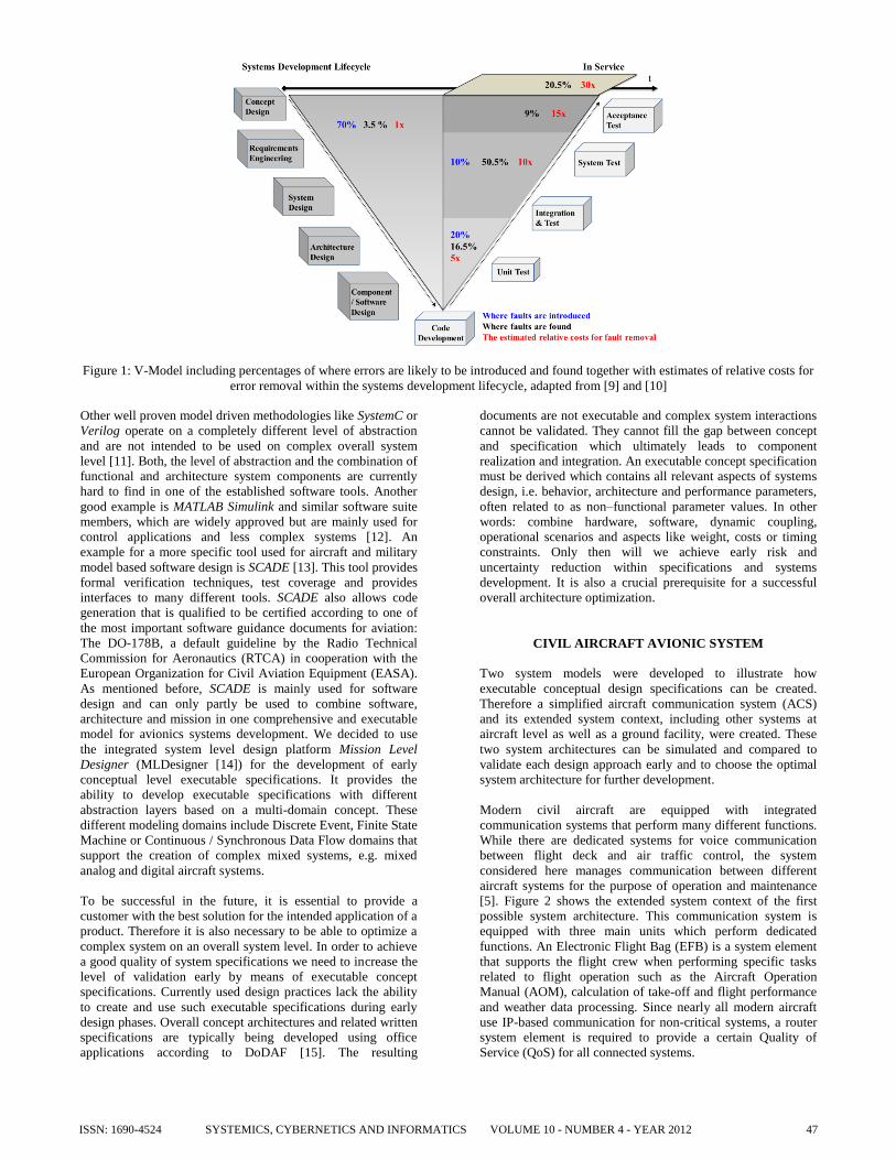
Figure 1: V-Model including percentages of where errors are likely to be introduced and found together with estimates of relative costs for
error removal within the systems development lifecycle, adapted from [9] and [10]
Other well proven model driven methodologies like SystemC or
Verilog operate on a completely different level of abstraction
and are not intended to be used on complex overall system
level [11]. Both, the level of abstraction and the combination of
functional and architecture system components are currently
hard to find in one of the established software tools. Another
good example is MATLAB Simulink and similar software suite
members, which are widely approved but are mainly used for
control applications and less complex systems [12]. An
example for a more specific tool used for aircraft and military
model based software design is SCADE [13]. This tool provides
formal verification techniques, test coverage and provides
interfaces to many different tools. SCADE also allows code
generation that is qualified to be certified according to one of
the most important software guidance documents for aviation:
The DO-178B, a default guideline by the Radio Technical
Commission for Aeronautics (RTCA) in cooperation with the
European Organization for Civil Aviation Equipment (EASA).
As mentioned before, SCADE is mainly used for software
design and can only partly be used to combine software,
architecture and mission in one comprehensive and executable
model for avionics systems development. We decided to use
the integrated system level design platform Mission Level
Designer (MLDesigner [14]) for the development of early
conceptual level executable specifications. It provides the
ability to develop executable specifications with different
abstraction layers based on a multi-domain concept. These
different modeling domains include Discrete Event, Finite State
Machine or Continuous / Synchronous Data Flow domains that
support the creation of complex mixed systems, e.g. mixed
analog and digital aircraft systems.
To be successful in the future, it is essential to provide a
customer with the best solution for the intended application of a
product. Therefore it is also necessary to be able to optimize a
complex system on an overall system level. In order to achieve
a good quality of system specifications we need to increase the
level of validation early by means of executable concept
specifications. Currently used design practices lack the ability
to create and use such executable specifications during early
design phases. Overall concept architectures and related written
specifications are typically being developed using office
applications according to DoDAF [15]. The resulting
documents are not executable and complex system interactions
cannot be validated. They cannot fill the gap between concept
and specification which ultimately leads to component
realization and integration. An executable concept specification
must be derived which contains all relevant aspects of systems
design, i.e. behavior, architecture and performance parameters,
often related to as non–functional parameter values. In other
words: combine hardware, software, dynamic coupling,
operational scenarios and aspects like weight, costs or timing
constraints. Only then will we achieve early risk and
uncertainty reduction within specifications and systems
development. It is also a crucial prerequisite for a successful
overall architecture optimization.
CIVIL AIRCRAFT AVIONIC SYSTEM
Two system models were developed to illustrate how
executable conceptual design specifications can be created.
Therefore a simplified aircraft communication system (ACS)
and its extended system context, including other systems at
aircraft level as well as a ground facility, were created. These
two system architectures can be simulated and compared to
validate each design approach early and to choose the optimal
system architecture for further development.
Modern civil aircraft are equipped with integrated
communication systems that perform many different functions.
While there are dedicated systems for voice communication
between flight deck and air traffic control, the system
considered here manages communication between different
aircraft systems for the purpose of operation and maintenance
[5]. Figure 2 shows the extended system context of the first
possible system architecture. This communication system is
equipped with three main units which perform dedicated
functions. An Electronic Flight Bag (EFB) is a system element
that supports the flight crew when performing specific tasks
related to flight operation such as the Aircraft Operation
Manual (AOM), calculation of take-off and flight performance
and weather data processing. Since nearly all modern aircraft
use IP-based communication for non-critical systems, a router
system element is required to provide a certain Quality of
Service (QoS) for all connected systems.
SYSTEMICS, CYBERNETICS AND INFORMATICS VOLUME 10 - NUMBER 4 - YEAR 2012 47ISSN: 1690-4524

Figure 2: System level and extended system context with three
dedicated system elements
Civil aircraft use so called Built-in Test equipment (BITE) to
constantly monitor connected components and report any
unusual behavior to the Centralized Maintenance System
(CMS). Most systems also require correlating maintenance data
and sending part of the information about the state of other
systems to the ground via the maintenance system element. The
second system architecture is depicted in Figure 3. In this
approach, the communication system is equipped with only two
units. The router system element is unchanged while EFB and
maintenance system element are realized within one integrated
unit.
Figure 3: System level and extended system context with two
dedicated system elements
Both system models represent identical functional behavior. All
double arrowed lines in both pictures represent communication
and data channels which are used to exchange data between
connected entities. These communication lines are also
considered as essential architecture elements of the system and
its context. Therefore, they are included in the model. In this
example, all system connections at aircraft level are considered
as IP-based networks the ground link is established via radio
link. For more in depth information on aircraft related systems,
design approaches and principles see references [16] and [17].
EARLY CONCEPTUAL MODEL-BASED DESIGN
In current approaches of complex systems design such as
aircraft, structured approaches are widely used. The design task
is decomposed through various design stages until the
remaining complexity permits to develop buildable solutions.
All these buildable solutions need to be assembled into a
complete system to solve the overall design problem. Dividing
a complex design problem into a number of less complex
problems and assembling these partial solutions is an approach
widely accepted [18], [19], [20]. Usually, system and concept
designers concentrate on operational and functional aspects of a
system under design. Physical architecture, resource
dimensioning and performance compliance is left to the
implementer or an external supplier. However, concentration
on a purely functional design without any reference to a
reasonable architecture is not sufficient [21]. Also, a holistic
design process needs to look at problems that may arise from
system integration. An overall solution which is assembled
from operative standalone sub-solutions may not work at all.
Therefore it is necessary to begin conceptual design at aircraft
level [22].
Usually, a conceptual design is generated at the very first levels
of systems design. Most concepts are derived from top-level
operational needs and customer inputs. While the concept is
steadily decomposed into sub-concepts and top-level
specifications are created, system and function designers assign
a set of attributes to each derived function. Thus, the designer
makes assumptions about a possible implementation of the
function being defined. These assumptions may also be based
on experience from previous projects and/or similar designs.
Consequently, a design decision about a functional architecture
is not based on functional aspects alone, but rather influenced
by the implicit assumptions about the physical architecture that
the designer made. The system specification however does not
explicitly state these assumptions thus making it difficult to
validate all requirements [5]. To overcome this validation gap,
executable concept specifications have been created for the two
different civil aircraft communication system architectures
using the design tool MLDesigner.
An executable concept specification binds logical behavior
(Function), architecture components (Elements) and
performance constraints and requirements as well as specific
resources in one combined multi-domain model. Resources are
either allocated to Functions, Elements or (Sub-) Systems
whereas Functions are allocated to Elements or standalone.
Simulations are used to validate the system design as early as
possible and to solve typical integration problems during
design, not during implementation and test. In a first step, a
functional model without any reference to any architecture was
created. Figure 4 shows the ACS module in MLDesigner. This
model is used as an operational baseline for the overall
concept. It is also used to show the difference between purely
functional and architectural executable specifications. General
aspects of a so called Function model block at conceptual level
are depicted in Figure 5. A Function is an MLDesigner module
that does describe logical behavior formed by different coupled
functional building blocks or C++ code. In other words, logical
behavior is composed of inputs, processing and outputs.
SYSTEMICS, CYBERNETICS AND INFORMATICS VOLUME 10 - NUMBER 4 - YEAR 201248 ISSN: 1690-4524
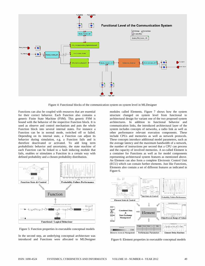
Figure 4: Functional blocks of the communication system on system level in MLDesigner
Functions can also be coupled with resources that are essential
for their correct behavior. Each Function also contains a
generic Finite State Machine (FSM). This generic FSM is
bound with the behavior of the respective Function block. It is
used as observe and control mechanism and puts the whole
Function block into several internal states. For instance a
Function can be in normal mode, switched off or failed.
Depending on its internal state, a Function can adjust its
behavior during simulation, e.g. a Function fails and is
therefore deactivated or activated. To add long term
probabilistic behavior and uncertainty, the state machine of
each Function can be linked to a fault inducing module that
fails, enables or stimulates a Function in a certain way with
defined probability and a chosen probability distribution.
Figure 5: Function properties in executable conceptual models
In the second step, an underlying conceptual architecture was
introduced and Functions were allocated to MLDesigner
modules called Elements. Figure 7 shows how the system
structure changed on system level from functional to
architectural design for variant one of the two proposed system
architectures. In addition to functional behavior and
communication links, the introduced architectural layer of the
system includes concepts of networks, a radio link as well as
other performance relevant execution components. These
include CPUs and memories as well as network protocols.
These concepts introduce additional model parameters, such as
the average latency and the maximum bandwidth of a network,
the number of instructions per second that a CPU can process
and the capacity of involved memories. A so-called Element is
a container for Functions as well as for model components
representing architectural system features as mentioned above.
An Element can also form a complete Electronic Control Unit
(ECU) which can contain further elements. Just like Functions,
Elements also contain a set of different features as indicated in
Figure 6.
Figure 6: Element properties in executable conceptual models
SYSTEMICS, CYBERNETICS AND INFORMATICS VOLUME 10 - NUMBER 4 - YEAR 2012 49ISSN: 1690-4524

Figure 7: Variant 1 of the communication systems conceptual architecture in MLDesigner containing 3 ECUs and 2 network Elements
Several, often called non-functional or quality parameters, like
cost and weight are also associated with elements. Each
Element has a set of non-functional parameters. These are used
during system simulation to calculate different non-functional
values for the whole system architecture. In order to be able to
validate a design and determine the best possible architecture
from a set of variants, so called Objectives have been
introduced. Objectives are 4-tuples of weighted parameter
values and can be used for either system validation or to
specify non-functional parameters, defining ranges instead of
single point values.
Objective = (value, lower bound, upper bound, weight)
Objectives have to be met by the overall system or a sub-set of
its Elements and Functions. Typical objectives given for
aircraft are weight, cost or timing constraints for the
completion of an important function or the Mean Time to
Restore (MTTR).
Quantifiable and adjustable shared resources like power or
bandwidth are directly coupled with Element and Function
execution for all conceptual models. Elements and Functions
specify their individual need or range for certain resources. If a
global or local resource like power is not available or does not
fulfill the demand given by an Element objective, the Element
will stop its execution and therefore the execution of all its
allocated Functions until all needed resources are available
again.
Elements also have a generic FSM based internal state control.
By default, but not limited to, an Element has four top-level
states: Normal, Failed, Off and Unpowered. In combination
with Function states it is now possible to let an element behave
normally, failed or partially failed. It can also be switched off
through stimulation by other Elements and Functions if
necessary. All generic states can be extended through
hierarchical decomposition into sub-states. For instance the
top-level Normal state could host several sub-states like
Maintenance or Test Mode, as depicted in Figure 8. If, for
example, an Element or an entire system is in Test Mode, only
a sub-set of specific functions are available to be performed.
Probabilistic fault inducing routines are used to emulate
failures as they happen in real world electronics like Line
Replaceable Units (LRUs).
Figure 8: Possible slave states of the Normal state of an
Element FSM
All Elements communicate through a defined set of
standardized data structures. This is necessary to guarantee a
consistent data particle exchange within each model. Since the
structure for all messages between Elements is known,
predefined plug-and-play model probes can be deployed for
data mining during simulation. It is also possible to use specific
delay routines within each element. These routines delay
allocated functions and data generated or processed within an
Element. Possible delay values can depend on available
bandwidth, cable length, CPU and memory execution delays to
name just a few. Precise value ranges for delays are determined
from data available for specific architecture Elements, expert
knowledge or in form of plausibility values, derived from
previous development projects or tests. During early design
SYSTEMICS, CYBERNETICS AND INFORMATICS VOLUME 10 - NUMBER 4 - YEAR 201250 ISSN: 1690-4524

levels, such aspects are often only vaguely known or unknown.
In this case, system designers can use more abstract Element
and sub-system execution delay modules in MLDesigner.
These are designed in a way to estimate the maximum amount
of delay which still enables an Element, a sub-system or the
complete system under design to perform all Functions while
simultaneously fulfilling necessary Objectives like time
constraints for the execution of a set of Functions. To do so,
executable conceptual specifications are iterated multiple
times, according to the algorithm shown in Figure 9. The
algorithm stops when a predefined maximum number of
iterations are completed or the calculated delay value for one or
more Elements has the expected accuracy. Accuracy is
determined through the number of decimal places of the
calculated delay value. Before starting a set of simulations,
different parameters can be set for the model and each
designated Element, for example:
Simulation counter: simc = max
Counter for the number of aborted simulations: x = 0
Step size for the add-on delay for each iteration: n = 1
Initial Element delay: e_delay = 0
Number of decimal places for the delay value: q = max
Last stable Element delay: s_delay = 0
Figure 9: Sequence plan for maximum valid Element delay
calculation through iteration with MLDesigner
When the algorithm has finished, delay values are available for
all Elements and/or sub-systems within a system. The
conceptual specification is complemented with these values
and validated through system execution. To validate the design,
Mission, Objectives and scenarios or use-cases are utilized
during system execution. On the one hand, calculated delay
values can be used by system designers to develop or order
fitting electronics for each Element and the respective set of
allocated Functions. On the other hand, different development
teams can also validate their detailed conceptual design for a
certain Element or a sub-system from the system under design.
Let’s say the algorithm determined a maximum delay value of
3.5 ms for the EFB Element and the Network 2 Element in
variant 1, shown in Figure 7. This means, that the complete
communication systems can perform all Functions according to
the given Objectives. It also means, the EFB Element itself can
carry out all its allocated Functions with the requested
performance, although the EFB Element delays the execution
of its Functions and the Network 2 Element delays the
transmission of data to and from the EFB Element by 3.5 ms.
The system architect of the communication system decides to
choose variant 1 and gives the executable specification to
another system designer who develops the EFB. He creates an
executable specification for the EFB and validates it with the
executable specification he has been given. His design is valid
as long as his design provides all necessary EFB Functions,
meets all Objectives and, among other constraints, provides a
maximum delay of 3.5 ms for the EFB. The same mechanism
can be applied for sub-system and network design
Both system architecture variants use a set of identical
Functions, defined by the functional model. Variant 1 allocates
EFB and Maintenance Functions to two dedicated elements
within the communication system, while variant 2 uses one
element to host all these Functions together. The same Router
Element is used in both variants to host all Routing Functions.
Accordingly, variant 1 uses five (internal and external) network
Elements and a radio link Element whereas variant 2 uses four
network Elements and a radio link to communicate with other
systems. In variant 2, network traffic from the combined EFB
and Maintenance System Element is transmitted using the same
system internal network, thus increasing the bandwidth
demand. Additionally, the CPU and memory resources must be
capable to satisfy the demand of both functions simultaneously.
VIRTUAL VALIDATION ENVIRONMENT
A global system application or mission is used to guarantee
repeatable simulations for all models and to validate each
model. To introduce features as depicted in Figure 5 and Figure
6, it was necessary to:
a) Implement an overall synchronicity method that
controls and synchronizes all model components.
b) Develop and use a consistent data base and a
standardized, coherent data exchange management
between Elements.
c) Use ranges instead of point values for parameters
during simulation to include uncertainty.
Several plug-and-play model components have been created to
help system designers to form executable conceptual
specifications with Functions and Elements. These include
several basic model components such as:
Delay modules for execution and transmission
behavior.
Probability driven failure generators.
Network components and other predefined Elements.
Objective test modules.
Resource management components.
Global and local system, Element and Function
control modules.
Evaluation probes, showing statistics and value
ranges (min, max, mean graphs).
Automation routines for maximum delay estimation
and state based coverage testing for different model
components.
On extended system level, a control module is used to
manipulate system, Element and Function behavior directly
during simulation. A prototypical graphical user interface
(GUI) was implemented to show and change the status of each
system, Element and Function.
SYSTEMICS, CYBERNETICS AND INFORMATICS VOLUME 10 - NUMBER 4 - YEAR 2012 51ISSN: 1690-4524

Figure 10: Automatically created GUI to observe (right hand side) and control (left hand side) the execution of different systems, Elements
and Functions during simulation of the communication system
The control GUI is created automatically during simulation and
according to the systems architecture. Figure 10 depicts the
GUI generated for variant 1. On the left hand side of Figure 10,
buttons where formed that can activate or deactivate a (sub-)
system, Element or Function. On the right hand side, there is an
indication for the status of each associated system component.
If any Function, Element or sub-system failure is detected it is
shown automatically. Identifiers within the GUI are created
according to the following expression:
<(S) System identifier # (E) Element identifier # (F) Function
identifier>
If for instance a whole subsystem is deactivated, all of its
functionalities fail and Elements will stop providing resources
they normally would produce. Figure 11 depicts how the
manipulation of one of the maintenance Functions and the
complete deactivation of the EFB Element dynamically affect
several systems and Elements (LRUs, networks) as well as
Functions within other areas of the conceptual system during
simulation. Small red boxes represent the number of impacted
Functions within other Elements and systems. Red network
connections indicate that the performances of nearly all
networks within the overall system are affected.
In addition, an auto execution mode is available, which will
automatically generate different state permutations during
simulation. This encloses all generic FSMs for sub-systems,
Functions and Elements. Using the possibilities of the GUI and
the possibility to control and change the state of each Function
for the example system, an over-sized periodic maintenance
Function could be determined immediately monitoring the
systems networks. The respective Function was sending data
via the radio link network too frequent, thus generating a
constant over utilization. Because of this, the performance of
other Functions and Elements of the system under design and
its interfaced systems was reduced to a non-acceptable degree.
The periodic Function was modified slightly to adjust to given
system architecture parameters thus resolving the problem at a
very early stage of design. Another important applications for
the features described are safety and reliability critical aircraft
systems. By activation / deactivation of Functions, Elements or
systems one can determine the robustness of a given system
architecture. Questions like “Will the system still work as
required if one particular Function or Element or a coupled
system fails?” or “Will all redundancy mechanisms work?” can
now be checked during simulation before system integration
has even started.
Figure 11: Impact of Function / Element deactivation on other
systems, Elements and Functions during simulation
SIMULATION AND RESULTS
Since all concept specifications are executable, it is possible to
draw conclusions from every model. The functional model
alone however, can only be used to validate, if logical
SYSTEMICS, CYBERNETICS AND INFORMATICS VOLUME 10 - NUMBER 4 - YEAR 201252 ISSN: 1690-4524

operational and functional aspects of the concept were
implemented correctly. Figure 12 shows the results for data
transmission from the cockpit to the EFB. Each dot represents a
datagram that is sent or received. This result is not very
realistic as each datagram is immediately received upon
transmission. Usually a delay would occur which is generated
by the time for data transmission through several networks,
data calculation and access operations by the EFB. This shows
that a purely functional model of a system is not sufficient for
validating system architectures.
Figure 12: Cockpit/EFB data exchange of the Functional model
The same simulation statistic used for variant 1 of the
conceptual specification produces a more realistic data
exchange diagram, shown in Figure 13.
Figure 13: Cockpit/EFB data exchange of the conceptual model
After both conceptual architecture simulations are completed, a
table with all Objective values is created and used to compare
the results for the different architectures. Table 1 lists the
results of the simulation for the two conceptual architectures.
The left row specifies all given objectives for the architecture.
Objectives beginning with a capital T mark timing objectives.
A timing Objective like T Flight Performance for instance
specifies a range from 0 ms to 4 ms. This means, that all
operations executed by different Functions to calculate data for
an aircraft function that constantly monitors the current
performance for flight shall never take longer than the upper
bound of 4 ms.
Objective Variant 1 Variant 2
T Maintenance (ms) 1,1036 1,1131
T Flight Performance (ms) 3,6616 3,6142
T AOM (ms) 5,1281 5,4920
T Weather Data (ms) 4,1515 3,7379
MTTR (h) 9,9107 9,8737
Total System Cost ($) 49500 43000
Total System Weight (kg) 101 86
Total Power Consumption (W) 2090 1810
Total System Size (MCU) 13 10
Total Heat Dissipation (units) 40,6999 31,8999
All Objectives Attainable Yes Yes
Table 1: Comparison of performance values of the two
conceptual system architectures
Other Objectives like Total System Cost are self-explanatory.
They represent non-functional parameters of the system under
design that have a huge impact on the development process.
The last line of Table 1 shows if all Objectives are attainable
for the respective design. Therefore, all table values are
compared with the given Objectives during simulation. Based
on all data, a design decision can be made. Of course, this
decision is strongly affected by the individual weights of each
Objective. However, a simple comparison is not enough when
validating system architectures. Specific properties of system
architectures, such as scalability and extensibility may also be
used to find a decision. Furthermore, the resource utilization
linked to a specific state of the system must be examined in
order to validate the dynamic behavior of the system. Different
MLDesigner modules are available to interfere with the
executable conceptual specification during simulation. A
simple slider, as depicted in Figure 14, can be used for instance
to change quantities of a certain resource like power to see the
direct impact on the system under design.
Figure 14: Slider to adjust the resource power within variant 1
Figure 15 compares the results of the simulations for data
transmission to the ground via radio link for both variants. This
result shows that the integration of several Functions into a
single Element incurs a burden on the resources that are
required to operate the system. The graph also shows that
additional delays are introduced when using the same set of
resources in one Element and that using one shared network
between different Elements increases delay for overall data
transmission.
Figure 15: Simulation results for air to ground data
transmission of variants B1 and B2
Network statistics of variant 1 and 2 for example can also be
used to determine the impact of reducing the number of internal
SYSTEMICS, CYBERNETICS AND INFORMATICS VOLUME 10 - NUMBER 4 - YEAR 2012 53ISSN: 1690-4524
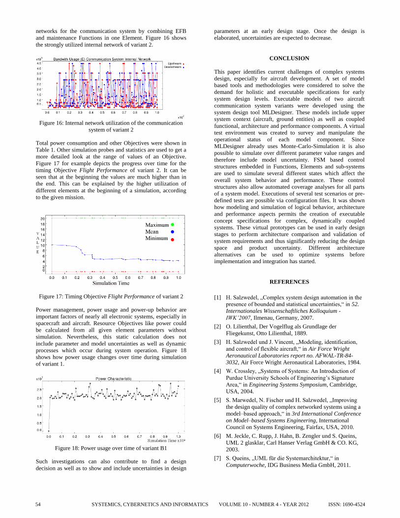
networks for the communication system by combining EFB
and maintenance Functions in one Element. Figure 16 shows
the strongly utilized internal network of variant 2.
Figure 16: Internal network utilization of the communication
system of variant 2
Total power consumption and other Objectives were shown in
Table 1. Other simulation probes and statistics are used to get a
more detailed look at the range of values of an Objective.
Figure 17 for example depicts the progress over time for the
timing Objective Flight Performance of variant 2. It can be
seen that at the beginning the values are much higher than in
the end. This can be explained by the higher utilization of
different elements at the beginning of a simulation, according
to the given mission.
Figure 17: Timing Objective Flight Performance of variant 2
Power management, power usage and power-up behavior are
important factors of nearly all electronic systems, especially in
spacecraft and aircraft. Resource Objectives like power could
be calculated from all given element parameters without
simulation. Nevertheless, this static calculation does not
include parameter and model uncertainties as well as dynamic
processes which occur during system operation. Figure 18
shows how power usage changes over time during simulation
of variant 1.
Figure 18: Power usage over time of variant B1
Such investigations can also contribute to find a design
decision as well as to show and include uncertainties in design
parameters at an early design stage. Once the design is
elaborated, uncertainties are expected to decrease.
CONCLUSION
This paper identifies current challenges of complex systems
design, especially for aircraft development. A set of model
based tools and methodologies were considered to solve the
demand for holistic and executable specifications for early
system design levels. Executable models of two aircraft
communication system variants were developed using the
system design tool MLDesigner. These models include upper
system context (aircraft, ground entities) as well as coupled
functional, architecture and performance components. A virtual
test environment was created to survey and manipulate the
operational status of each model component. Since
MLDesigner already uses Monte-Carlo-Simulation it is also
possible to simulate over different parameter value ranges and
therefore include model uncertainty. FSM based control
structures embedded in Functions, Elements and sub-systems
are used to simulate several different states which affect the
overall system behavior and performance. These control
structures also allow automated coverage analyses for all parts
of a system model. Executions of several test scenarios or pre-
defined tests are possible via configuration files. It was shown
how modeling and simulation of logical behavior, architecture
and performance aspects permits the creation of executable
concept specifications for complex, dynamically coupled
systems. These virtual prototypes can be used in early design
stages to perform architecture comparison and validation of
system requirements and thus significantly reducing the design
space and product uncertainty. Different architecture
alternatives can be used to optimize systems before
implementation and integration has started.
REFERENCES
[1] H. Salzwedel, „Complex system design automation in the
presence of bounded and statistical uncertainties,“ in 52.
Internationales Wissenschaftliches Kolloquium -
IWK’2007, Ilmenau, Germany, 2007.
[2] O. Lilienthal, Der Vogelflug als Grundlage der
Fliegekunst, Otto Lilienthal, 1889.
[3] H. Salzwedel und J. Vincent, „Modeling, identification,
and control of flexible aircraft,“ in Air Force Wright
Aeronautical Laboratories report no. AFWAL-TR-84-
3032, Air Force Wright Aeronautical Laboratories, 1984.
[4] W. Crossley, „Systems of Systems: An Introduction of
Purdue University Schools of Engineering’s Signature
Area,“ in Engineering Systems Symposium, Cambridge,
USA, 2004.
[5] S. Marwedel, N. Fischer und H. Salzwedel, „Improving
the design quality of complex networked systems using a
model–based approach,“ in 3rd International Conference
on Model–based Systems Engineering, International
Council on Systems Engineering, Fairfax, USA, 2010.
[6] M. Jeckle, C. Rupp, J. Hahn, B. Zengler und S. Queins,
UML 2 glasklar, Carl Hanser Verlag GmbH & CO. KG,
2003.
[7] S. Queins, „UML für die Systemarchitektur,“ in
Computerwoche, IDG Business Media GmbH, 2011.
SYSTEMICS, CYBERNETICS AND INFORMATICS VOLUME 10 - NUMBER 4 - YEAR 201254 ISSN: 1690-4524

[8] J. Holt und S. Perry, SysML for Systems Engineering
(Professional Applications of Computing), Institution of
Engineering and Technology, 2007.
[9] National Institute of Standards & Technology (NIST),
„The Economic Impacts of Inadequate Infrastructure for
Software Testing, pp.91 ff.,“ in Planning Report 02-3,
2002.
[10] P. H. Feiler, Model-based Engineering of Software-reliant
Systems with AADL, Pittsburgh, PA, USA: Software
Engineering Institute, Carnegie Mellon University , 2010.
[11] C. Grimm, Languages for System Specification: Selected
Contributions on UML, SystemC, System Verilog, Mixed-
Signal Systems, and Property Specifications from FDL'03,
Springer Netherlands, 2004.
[12] A. Angermann, M. Beuschel, M. Rau und U. Wohlfarth,
MATLAB - Simulink - Stateflow: Grundlagen,
Toolboxen, Beispiele, Oldenbourg Wissenschaftsverlag,
2009.
[13] [Online]. Available: http://www.esterel-technologies.com.
[Zugriff am May 2011].
[14] [Online]. Available: http://www.mldesigner.com. [Zugriff
am January 2012].
[15] Department of Defense, DOD Architecture Framework
(DoDAF) V1.5, Vols I, II, and III, Version 1.5 ed., USA,
2007.
[16] I. Moir und A. G. Seabridge, Civil Avionics Systems,
John Wiley & Sons, Ltd., 2006.
[17] I. Moir und A. G. Seabridge, Aircraft Systems:
Mechanical, Electrical and Avionics Subsystems
Integration, 3rd Edition, John Wiley & Sons, Ltd., 2008.
[18] B. S. Blanchard und W. B. Fabrycky, Systems
Engineering and Analysis 4th ed., Prentice Hall, 2005.
[19] D. Buede, The Engineering Design of Systems: Models
and Methods, John Wiley & Sons, 2000.
[20] A. P. Sage und J. E. Armstrong, Introduction to Systems
Engineering, John Wiley & Sons, 2000.
[21] N. Fischer, Design of a Plug-and-Play Development
Environment for Optimizing Avionics Systems
Architectures, Thesis: Ilmenau University of Technology,
2007.
[22] H. Salzwedel, N. Fischer und T. Baumann, „Aircraft level
optimization of avionics architectures,“ in 27th Digital
Avionics Conference – DASC 2008, St. Paul, USA.
SYSTEMICS, CYBERNETICS AND INFORMATICS VOLUME 10 - NUMBER 4 - YEAR 2012 55ISSN: 1690-4524