Embed Size (px)
Citation preview
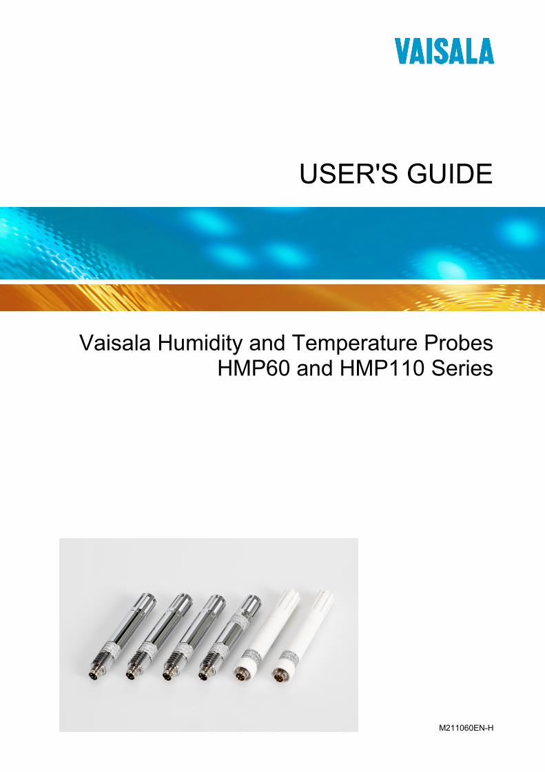
USER'S GUIDE
Vaisala Humidity and Temperature Probes HMP60 and HMP110 Series
M211060EN-H
PUBLISHED BY
Vaisala Oyj Street address: Vanha Nurmijärventie 21, FI-01670 Vantaa, Finland Mailing address: P.O. Box 26, FI-00421 Helsinki, Finland Phone: +358 9 8949 1 Fax: +358 9 8949 2227
Visit our Internet pages at www.vaisala.com
© Vaisala 2017
No part of this manual may be reproduced, published or publicly displayed in any form or by any means, electronic or mechanical (including photocopying), nor may its contents be modified, translated, adapted, sold or disclosed to a third party without prior written permission of the copyright holder. Translated manuals and translated portions of multilingual documents are based on the original English versions. In ambiguous cases, the English versions are applicable, not the translations.
The contents of this manual are subject to change without prior notice.
Local rules and regulations may vary and they shall take precedence over the information contained in this manual. Vaisala makes no representations on this manual’s compliance with the local rules and regulations applicable at any given time, and hereby disclaims any and all responsibilities related thereto.
This manual does not create any legally binding obligations for Vaisala towards customers or end users. All legally binding obligations and agreements are included exclusively in the applicable supply contract or the General Conditions of Sale and General Conditions of Service of Vaisala.
_________________________________________________________________________________
VAISALA _________________________________________________________________________ 1
Table of Contents
CHAPTER 1 GENERAL INFORMATION ............................................................................ 5
About This Manual ................................................................... 5 Contents of This Manual ....................................................... 5 Version Information ............................................................... 6 Related Manuals ................................................................... 6 Documentation Conventions ................................................. 7
Safety ......................................................................................... 7 ESD Protection ......................................................................... 7 Recycling .................................................................................. 8 Regulatory Compliances ......................................................... 8 Trademarks ............................................................................... 9 License Agreement .................................................................. 9 Warranty .................................................................................... 9
CHAPTER 2 PRODUCT OVERVIEW ................................................................................ 10
Introduction to HMP60 and HMP110 Series......................... 10 Basic Features and Options .................................................. 12
Output Options .................................................................... 13 Filter Options ....................................................................... 14
Installation Accessories (Optional) ...................................... 15 Probe Mounting Clamp ....................................................... 15 Probe Mounting Flange ....................................................... 17 Plastic Locking Bushing for HMP63 and HMP113 .............. 17 Duct Installation Kit for HMP60, HMP110, and HMP110T .. 18 Loop Power Converter ........................................................ 19 Cables ................................................................................. 20
CHAPTER 3 INSTALLATION ............................................................................................ 21
Dimensions for HMP60, HMP110, and HMP110T ................ 21 Dimensions for HMP63 and HMP113 .................................... 22 Mounting the HMP60, HMP110, and HMP110T Probes ....... 23
Probe Assembly with Duct Installation Kit ..................... 23 Drilling Instructions for Duct Installation Kit ................... 24
Mounting the HMP63 and HMP113 Probes .......................... 25 Wiring ...................................................................................... 26
Wiring Multiple Digital Devices ............................................ 27 Wiring with the Loop Power Converter ............................... 29 Power Supply Requirements ............................................... 30
Recommendations ......................................................... 30 CHAPTER 4 OPERATION ................................................................................................. 31
Getting Started ....................................................................... 31
User's Guide _______________________________________________________________________
2 ____________________________________________________________________ M211060EN-H
Serial Line Communication ................................................... 31 Connecting to the Serial Interface ....................................... 31 Installing the Driver for the USB Cable ................................ 33 Terminal Application Settings for Digital Probes ................. 34 Accessing Serial Line Command Interface (RS-485 Mode) from Analog or Modbus Mode ................... 36
Modbus Communication ........................................................ 37 Using Multiple Devices over RS-485 ................................... 38
List of Serial Commands ....................................................... 39 Device Information and Status .............................................. 40
View Device Information ...................................................... 40 View Calibration Information ............................................... 41 Enter Calibration Information ............................................... 41 View Order Code ................................................................. 41 View Serial Number ............................................................. 42 View Software Version ........................................................ 42
Serial Line Output Commands .............................................. 42 Start Measurement Output .................................................. 42 Stop Measurement Output .................................................. 43 Output the Measurement Message Once ........................... 43
Configuring Serial Line Operation ........................................ 43 Set Serial Line Settings ....................................................... 43 Set Serial Interface Mode .................................................... 44 Set Output Interval ............................................................... 45 Set Measurement Filtering .................................................. 45 Set Probe Address .............................................................. 46 Set Serial Interface Delay .................................................... 46 Set Measurement Units ....................................................... 47
Calibration Commands .......................................................... 48 Calibrate Humidity Measurement ........................................ 48 Clear Adjustment of RH Measurement ................................ 49 Calibrate Temperature Measurement ................................. 49 Clear Adjustment of T Measurement ................................... 50 View User Adjustment Parameters ..................................... 50
Other Commands.................................................................... 51 Set Analog Output Mode ..................................................... 51 Set Analog Output Parameters and Scaling........................ 52 Set Analog Output Error Indication Level ............................ 53 Extend Analog Output Range .............................................. 54 Extend Maximum RH Reading ............................................ 54 Display Command List......................................................... 55 Display the Currently Active Errors ..................................... 55 Connect to the Probe in POLL Mode .................................. 55 Close the Connection in POLL Mode .................................. 56 Reset the Probe ................................................................... 56 Restore Factory Settings ..................................................... 56
CHAPTER 5 MAINTENANCE ............................................................................................ 57
Periodic Maintenance ............................................................. 57 Cleaning .............................................................................. 57 Changing the Filter .............................................................. 57
Calibration Procedure ............................................................ 58 Adjustment Procedure Using Serial Line (HMP110 and HMP113) ........................................................... 58
_________________________________________________________________________________
VAISALA _________________________________________________________________________ 3
One-Point Adjustment of RH Measurement (HMP110 and HMP113) ...................................................... 58 Two-Point Adjustment of RH Measurement (HMP110 and HMP113) ...................................................... 60 One-Point Adjustment of T Measurement (HMP110, HMP113, and HMP110T) .................................. 61
Adjustment Procedure Using MI70 Indicator (HMP110 and HMP113) ........................................................... 63
One-Point Adjustment of RH Measurement (HMP110 and HMP113) ...................................................... 63 One-Point Adjustment of Temperature Measurement ........ 64
Repair Maintenance ............................................................... 65 Changing the INTERCAP® Sensor (HMP60 and HMP63) .......................................................... 65 Changing the HUMICAP® 180R/180V Sensor (HMP110 and HMP113) ...................................................... 66
CHAPTER 6 TROUBLESHOOTING ................................................................................. 67
Analog Output Error Notification .......................................... 67 Solving Typical Problems...................................................... 67 Technical Support .................................................................. 68
CHAPTER 7 TECHNICAL DATA ...................................................................................... 69
Specifications ......................................................................... 69 Performance (HMP60 and HMP63) .................................... 69
Relative Humidity ........................................................... 69 Temperature ................................................................... 69 Dewpoint ........................................................................ 69
Performance (HMP110) ...................................................... 70 Relative Humidity ........................................................... 70 Temperature ................................................................... 70 Dewpoint ........................................................................ 70
Performance (HMP113) ...................................................... 71 Relative Humidity ........................................................... 71 Temperature ................................................................... 71 Dewpoint ........................................................................ 71
Performance (HMP110T) .................................................... 71 Temperature ................................................................... 71
Operating Environment ....................................................... 72 Inputs and Outputs .............................................................. 72 Mechanics (HMP60, HMP110, and HMP110T) .................. 73 Mechanics (HMP63 and HMP113) ..................................... 73
Options and Accessories ...................................................... 74 APPENDIX A MODBUS REFERENCE ............................................................................... 75
Supported Modbus Functions .............................................. 75 Modbus Register Map ............................................................ 76 Device Identification Objects ................................................ 78 Communication Test Registers ............................................ 78
User's Guide _______________________________________________________________________
4 ____________________________________________________________________ M211060EN-H
List of Figures
Figure 1 HMP60 and HMP110 Series Probes ........................................ 11 Figure 2 Filters for HMP60, HMP110, and HMP110T ............................ 14 Figure 3 Filters for HMP63 and HMP113 ................................................ 14 Figure 4 Probe Mounting Clamp in Use .................................................. 15 Figure 5 Aligning Mounting Clamp Slots ................................................. 15 Figure 6 Sliding the Lower Clamp Part ................................................... 16 Figure 7 Securing the Upper Clamp Part ................................................ 16 Figure 8 Probe Mounting Flange ............................................................ 17 Figure 9 HMP113 with Plastic Locking Bushing ..................................... 17 Figure 10 Probe Installation with the Duct Installation Kit ........................ 18 Figure 11 Loop Power Converter .............................................................. 19 Figure 12 Cable with Threaded Connector ............................................... 20 Figure 13 USB Serial Interface Cable ....................................................... 20 Figure 14 HMP60, HMP110, and HMP110T Dimensions ........................ 21 Figure 15 Installation with Plastic M12 Nuts, Dimensions ........................ 21 Figure 16 HMP63 and HMP113 Dimensions ............................................ 22 Figure 17 HMP63 and HMP113 with Plastic Locking Bushing,
Dimensions ............................................................................... 22 Figure 18 Assembly of the Probe with Duct Installation Kit ...................... 23 Figure 19 Drilling Instructions ................................................................... 24 Figure 20 Wiring of Analog Output ........................................................... 26 Figure 21 Wiring of Digital Output ............................................................. 26 Figure 22 Wiring Multiple Devices Using Local Power Supply ................. 27 Figure 23 Wiring Multiple Devices Using Common Power Supply ........... 28 Figure 24 Wiring with the Loop Power Converter Module ........................ 29 Figure 25 PuTTY Terminal Application ..................................................... 35 Figure 26 INTERCAP® Sensor ................................................................ 65 Figure 27 Removing the Sensor ............................................................... 65 Figure 28 HUMICAP® 180R Sensor ........................................................ 66
List of Tables Table 1 Manual Revisions ....................................................................... 6 Table 2 Related Manuals ......................................................................... 6 Table 3 Parameters Measured by HMP60 and HMP110 Series ........... 10 Table 4 HMP60 and HMP110 Series Output Options ........................... 13 Table 5 Grounding Methods .................................................................. 26 Table 6 Pinout of the Probe Connector ................................................. 27 Table 7 Operating Voltage Ranges ....................................................... 30 Table 8 Default Serial Communication Settings .................................... 32 Table 9 Default Modbus Communication Settings ................................ 37 Table 10 Serial Line Configuration Commands for Modbus RTU ........... 37 Table 11 List of Serial Commands (software version 2.0.7) .................... 39 Table 12 Additional Commands for Probes with RS-485 Output ............ 40 Table 13 Serial Interface Modes .............................................................. 44 Table 14 Troubleshooting Table .............................................................. 67 Table 15 Options and Accessories .......................................................... 74 Table 16 Connection Cables ................................................................... 74 Table 17 Supported Function Codes ....................................................... 75 Table 18 Modbus Register Map (Measurement Values and Settings) .... 76 Table 19 Device Identification Objects .................................................... 78 Table 20 Communication Test Registers ................................................ 78
Chapter 1 _________________________________________________________ General Information
VAISALA _________________________________________________________________________ 5
CHAPTER 1
GENERAL INFORMATION
This chapter provides general notes for the manual and the HMP60 and HMP110 series probes.
About This Manual This manual provides information for installing, operating, and maintaining HMP60 and HMP110 series probes.
Contents of This Manual This manual consists of the following chapters:
- Chapter 1, General Information, provides general notes for the manual and the HMP60 and HMP110 series probes.
- Chapter 2, Product Overview, introduces the features and options of the HMP60 and HMP110 series probes.
- Chapter 3, Installation, provides you with information that is intended to help you install the HMP60 and HMP110 series probes.
- Chapter 4, Operation, contains information that is needed to operate the HMP60 and HMP110 series probes.
- Chapter 5, Maintenance, provides information that is needed in basic maintenance of the HMP60 and HMP110 series probes.
- Chapter 6, Troubleshooting, describes common problems, their probable causes and remedies, and contact information for technical support.
- Chapter 7, Technical Data, provides the technical data of the HMP60 and HMP110 series probes.
User's Guide _______________________________________________________________________
6 ____________________________________________________________________ M211060EN-H
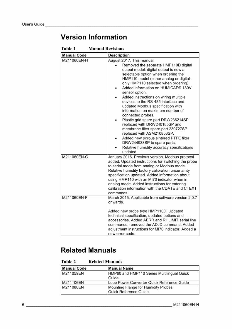
Version Information Table 1 Manual Revisions Manual Code Description M211060EN-H August 2017. This manual.
• Removed the separate HMP110D digital output model: digital output is now a selectable option when ordering the HMP110 model (either analog or digital-only HMP110 selected when ordering).
• Added information on HUMICAP® 180V sensor option.
• Added instructions on wiring multiple devices to the RS-485 interface and updated Modbus specification with information on maximum number of connected probes.
• Plastic grid spare part DRW236214SP replaced with DRW240185SP and membrane filter spare part 230727SP replaced with ASM210856SP.
• Added new porous sintered PTFE filter DRW244938SP to spare parts.
• Relative humidity accuracy specifications updated
M211060EN-G January 2016. Previous version. Modbus protocol added. Updated instructions for switching the probe to serial mode from analog or Modbus mode. Relative humidity factory calibration uncertainty specification updated. Added information about using HMP110 with an MI70 indicator when in analog mode. Added instructions for entering calibration information with the CDATE and CTEXT commands.
M211060EN-F March 2015. Applicable from software version 2.0.7 onwards. Added new probe type HMP110D. Updated technical specification, updated options and accessories. Added AERR and RHLIMIT serial line commands, removed the ADJD command. Added adjustment instructions for MI70 indicator. Added a new error code.
Related Manuals Table 2 Related Manuals Manual Code Manual Name M211059EN HMP60 and HMP110 Series Multilingual Quick
Guide M211106EN Loop Power Converter Quick Reference Guide M211080EN Mounting Flange for Humidity Probes
Quick Reference Guide
Chapter 1 _________________________________________________________ General Information
VAISALA _________________________________________________________________________ 7
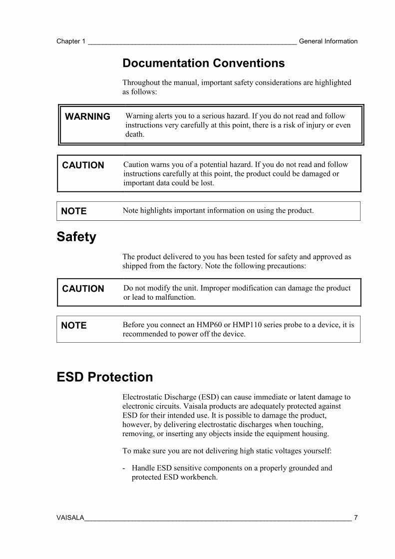
Documentation Conventions Throughout the manual, important safety considerations are highlighted as follows:
WARNING Warning alerts you to a serious hazard. If you do not read and follow instructions very carefully at this point, there is a risk of injury or even death.
CAUTION Caution warns you of a potential hazard. If you do not read and follow instructions carefully at this point, the product could be damaged or important data could be lost.
NOTE Note highlights important information on using the product.
Safety The product delivered to you has been tested for safety and approved as shipped from the factory. Note the following precautions:
CAUTION Do not modify the unit. Improper modification can damage the product or lead to malfunction.
NOTE Before you connect an HMP60 or HMP110 series probe to a device, it is recommended to power off the device.
ESD Protection Electrostatic Discharge (ESD) can cause immediate or latent damage to electronic circuits. Vaisala products are adequately protected against ESD for their intended use. It is possible to damage the product, however, by delivering electrostatic discharges when touching, removing, or inserting any objects inside the equipment housing.
To make sure you are not delivering high static voltages yourself:
- Handle ESD sensitive components on a properly grounded and protected ESD workbench.
User's Guide _______________________________________________________________________
8 ____________________________________________________________________ M211060EN-H
- When an ESD workbench is not available, ground yourself to the equipment chassis with a wrist strap and a resistive connection cord.
- If you are unable to take either of the above precautions, touch a conductive part of the equipment chassis with your other hand before touching ESD sensitive components.
- Always hold component boards by the edges and avoid touching the component contacts.
Recycling
Recycle all applicable material.
Do not dispose of with regular household refuse.
Regulatory Compliances HMP60 and HMP110 series probes are in conformity with the provisions of the following EU directive(s):
ROHS Directive EMC Directive
The electromagnetic compatibility of HMP60, HMP110, HMP110T, and HMP110REF has been tested according to the following product family standards:
- EN 61326-1: Electrical equipment for measurement, control and laboratory use - EMC requirements – for use in industrial locations.
- EN 55022 Class B: Information technology equipment - Radio disturbance characteristics - Limits and methods of measurement.
The electromagnetic compatibility of HMP63 and HMP113 has been tested according to the following product family standards:
- EN 61326-1: Electrical equipment for measurement, control and laboratory use - EMC requirements – Basic immunity test requirements.
- EN 55022 Class B: Information technology equipment - Radio disturbance characteristics - Limits and methods of measurement.
Chapter 1 _________________________________________________________ General Information
VAISALA _________________________________________________________________________ 9
Trademarks Vaisala INTERCAP® and Vaisala HUMICAP® are registered trademarks of Vaisala Oyj.
Windows® is a registered trademark of Microsoft Corporation in the United States and/or other countries.
License Agreement All rights to any software are held by Vaisala or third parties. The customer is allowed to use the software only to the extent that is provided by the applicable supply contract or Software License Agreement.
Warranty Visit our Internet pages for more information and our standard warranty terms and conditions: www.vaisala.com/warranty.
Please observe that any such warranty may not be valid in case of damage due to normal wear and tear, exceptional operating conditions, negligent handling or installation, or unauthorized modifications. Please see the applicable supply contract or Conditions of Sale for details of the warranty for each product.
User's Guide _______________________________________________________________________
10 ___________________________________________________________________ M211060EN-H
CHAPTER 2
PRODUCT OVERVIEW
This chapter introduces the features and options of the HMP60 and HMP110 series probes.
Introduction to HMP60 and HMP110 Series Vaisala Humidity and Temperature Probes HMP60 and HMP110 Series are simple and cost-effective humidity transmitters suitable for various volume applications:
- Integration into other manufacturers’ equipment. - Incubators. - Glove boxes. - Greenhouses. - Fermentation chambers. - Data loggers. - Hand-held meters.
HMP60 series probes use the interchangeable Vaisala INTERCAP® sensor. No recalibration is required after sensor replacement.
HMP110 series probes use the Vaisala HUMICAP® 180R sensor for increased accuracy. For applications where H2O2 (for example, vaporized hydrogen peroxide (VHP)) is present, HMP110 series probes can also be ordered with the HUMICAP® 180V catalytic sensor. HMP110 series probes require calibration after sensor replacement. This can be done on the serial line using the optional Vaisala USB cable.
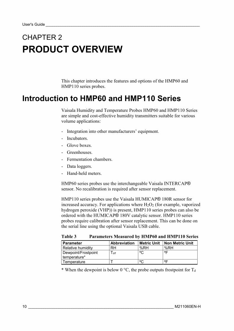
Table 3 Parameters Measured by HMP60 and HMP110 Series Parameter Abbreviation Metric Unit Non Metric Unit Relative humidity RH %RH %RH Dewpoint/Frostpoint temperature*
Td/f ºC ºF
Temperature T ºC ºF
* When the dewpoint is below 0 °C, the probe outputs frostpoint for Td
Chapter 2 ___________________________________________________________ Product Overview
VAISALA ________________________________________________________________________ 11
1210-009
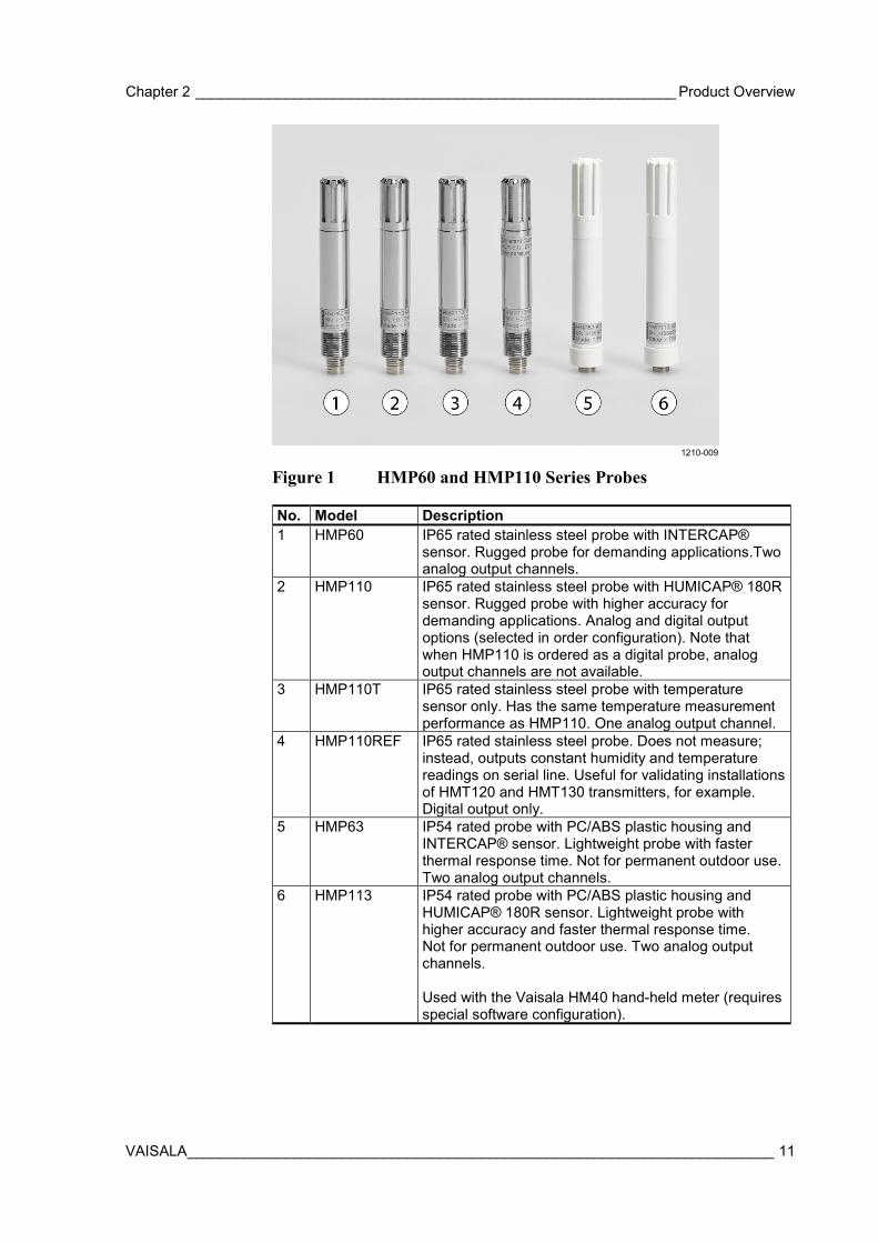
Figure 1 HMP60 and HMP110 Series Probes
No. Model Description 1 HMP60 IP65 rated stainless steel probe with INTERCAP®
sensor. Rugged probe for demanding applications.Two analog output channels.
2 HMP110 IP65 rated stainless steel probe with HUMICAP® 180R sensor. Rugged probe with higher accuracy for demanding applications. Analog and digital output options (selected in order configuration). Note that when HMP110 is ordered as a digital probe, analog output channels are not available.
3 HMP110T IP65 rated stainless steel probe with temperature sensor only. Has the same temperature measurement performance as HMP110. One analog output channel.
4 HMP110REF IP65 rated stainless steel probe. Does not measure; instead, outputs constant humidity and temperature readings on serial line. Useful for validating installations of HMT120 and HMT130 transmitters, for example. Digital output only.
5 HMP63 IP54 rated probe with PC/ABS plastic housing and INTERCAP® sensor. Lightweight probe with faster thermal response time. Not for permanent outdoor use. Two analog output channels.
6 HMP113 IP54 rated probe with PC/ABS plastic housing and HUMICAP® 180R sensor. Lightweight probe with higher accuracy and faster thermal response time. Not for permanent outdoor use. Two analog output channels. Used with the Vaisala HM40 hand-held meter (requires special software configuration).
User's Guide _______________________________________________________________________
12 ___________________________________________________________________ M211060EN-H
Basic Features and Options - Analog and digital output options:
- HMP60, HMP63, HMP110 and HMP113 analog output mode: two analog output channels, selectable from 0 ... 1 V / 0 ... 2.5 V / 0 ... 5 V / 1 ... 5 V.
- HMP110 digital output option (Modbus, RS-485, or VDIGI, selected when ordering): for permanent digital output installations, no analog output.
- HMP110T analog output mode: single analog output channel (CH1), selectable from 0 ... 1 V / 0 ... 2.5 V / 0 ... 5 V / 1 ... 5 V.
- RS-485 interface available for all models (Modbus RTU and temporary service access with Vaisala Industrial Protocol serial line communication).
- Small size. - Low power consumption. - IP65 stainless steel body on HMP60 and HMP110 models. - IP54 lightweight plastic body on HMP63 and HMP113 models. - Options and accessories:
- Several filter options; see section Filter Options on page 14. - Probe mounting clamp. - Probe mounting flange. - Duct installation kit for HMP60, HMP110, and HMP110T. - One channel loop power converter 4 ... 20 mA (separate module,
compatible with humidity accuracy only). - Shielded 0.3 m and 3.0 m connection cables with threaded
connector for probe connection, open end wires on the other end. - Plastic M12 installation nuts for HMP60, HMP110, and HMP110T. - Plastic locking bushing for HMP63 and HMP113 (for use with
Vaisala products, for example HM40 hand-held meter).
Chapter 2 ___________________________________________________________ Product Overview
VAISALA ________________________________________________________________________ 13
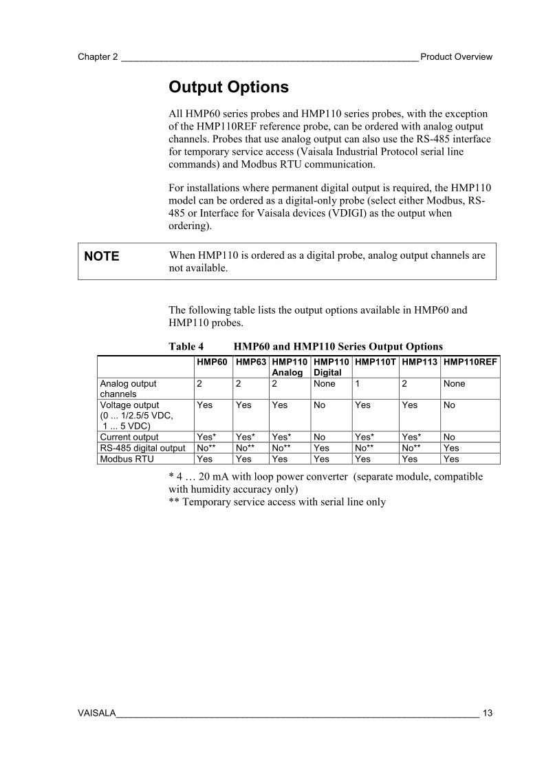
Output Options All HMP60 series probes and HMP110 series probes, with the exception of the HMP110REF reference probe, can be ordered with analog output channels. Probes that use analog output can also use the RS-485 interface for temporary service access (Vaisala Industrial Protocol serial line commands) and Modbus RTU communication.
For installations where permanent digital output is required, the HMP110 model can be ordered as a digital-only probe (select either Modbus, RS-485 or Interface for Vaisala devices (VDIGI) as the output when ordering).
NOTE When HMP110 is ordered as a digital probe, analog output channels are not available.
The following table lists the output options available in HMP60 and HMP110 probes.
Table 4 HMP60 and HMP110 Series Output Options HMP60 HMP63 HMP110
Analog HMP110 Digital
HMP110T HMP113 HMP110REF
Analog output channels
2 2 2 None 1 2 None
Voltage output (0 ... 1/2.5/5 VDC, 1 ... 5 VDC)
Yes Yes Yes No Yes Yes No
Current output Yes* Yes* Yes* No Yes* Yes* No RS-485 digital output No** No** No** Yes No** No** Yes Modbus RTU Yes Yes Yes Yes Yes Yes Yes
* 4 … 20 mA with loop power converter (separate module, compatible with humidity accuracy only) ** Temporary service access with serial line only
User's Guide _______________________________________________________________________
14 ___________________________________________________________________ M211060EN-H
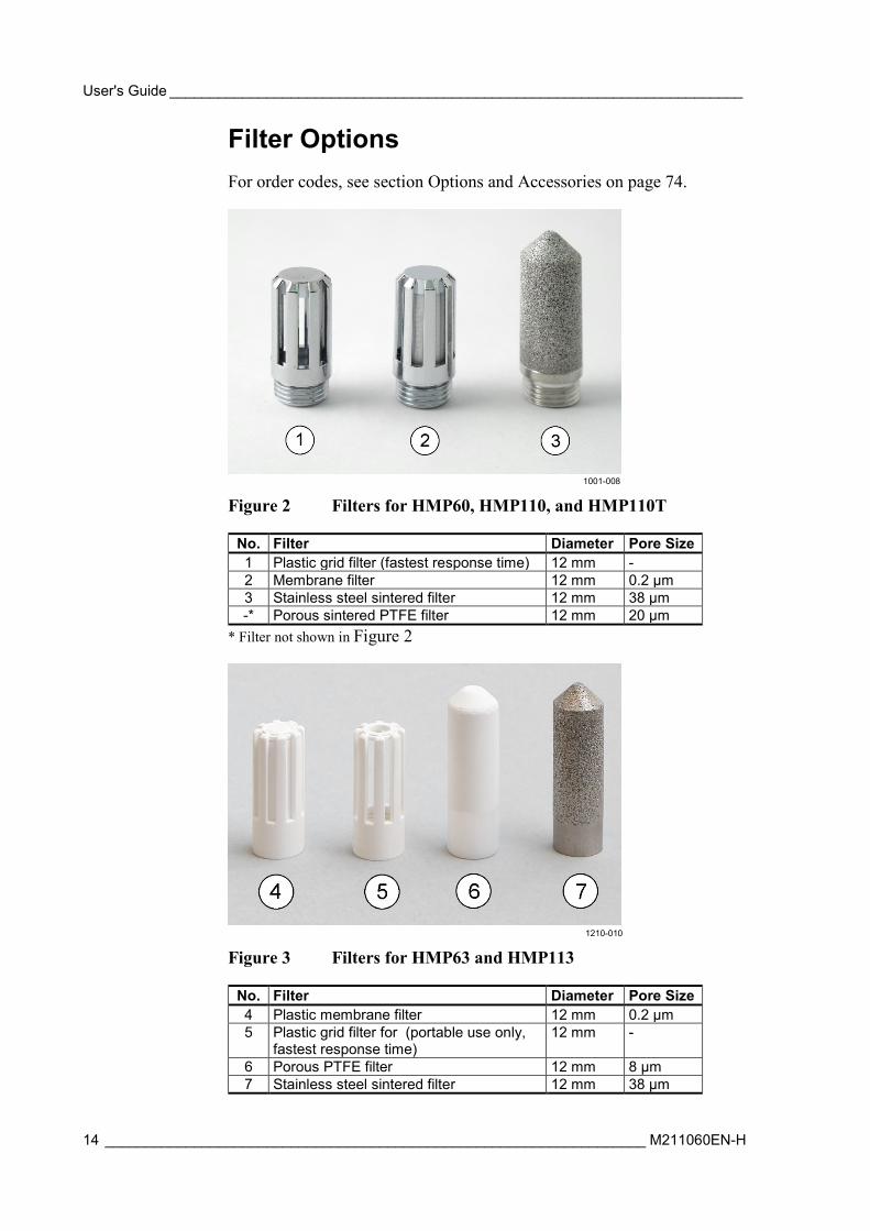
Filter Options For order codes, see section Options and Accessories on page 74.
1001-008
Figure 2 Filters for HMP60, HMP110, and HMP110T
No. Filter Diameter Pore Size 1 Plastic grid filter (fastest response time) 12 mm - 2 Membrane filter 12 mm 0.2 µm 3 Stainless steel sintered filter 12 mm 38 µm -* Porous sintered PTFE filter 12 mm 20 µm
* Filter not shown in Figure 2
1210-010
Figure 3 Filters for HMP63 and HMP113
No. Filter Diameter Pore Size 4 Plastic membrane filter 12 mm 0.2 µm 5 Plastic grid filter for (portable use only,
fastest response time) 12 mm -
6 Porous PTFE filter 12 mm 8 µm 7 Stainless steel sintered filter 12 mm 38 µm
Chapter 2 ___________________________________________________________ Product Overview
VAISALA ________________________________________________________________________ 15
Installation Accessories (Optional) For order codes, see section Options and Accessories on page 74.
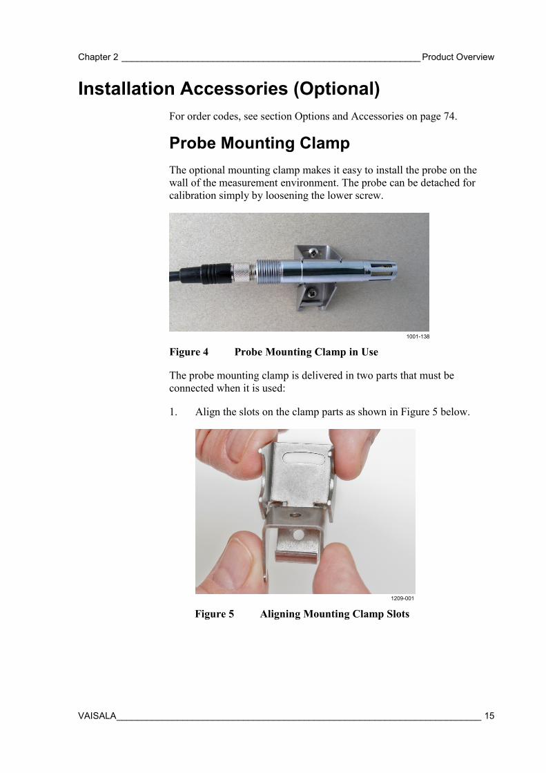
Probe Mounting Clamp The optional mounting clamp makes it easy to install the probe on the wall of the measurement environment. The probe can be detached for calibration simply by loosening the lower screw.
1001-138
Figure 4 Probe Mounting Clamp in Use
The probe mounting clamp is delivered in two parts that must be connected when it is used:
1. Align the slots on the clamp parts as shown in Figure 5 below.
1209-001
Figure 5 Aligning Mounting Clamp Slots
User's Guide _______________________________________________________________________
16 ___________________________________________________________________ M211060EN-H
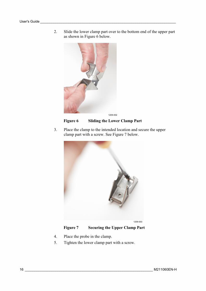
2. Slide the lower clamp part over to the bottom end of the upper part as shown in Figure 6 below.
1209-002
Figure 6 Sliding the Lower Clamp Part
3. Place the clamp to the intended location and secure the upper clamp part with a screw. See Figure 7 below.
1209-003
Figure 7 Securing the Upper Clamp Part
4. Place the probe in the clamp. 5. Tighten the lower clamp part with a screw.
Chapter 2 ___________________________________________________________ Product Overview
VAISALA ________________________________________________________________________ 17
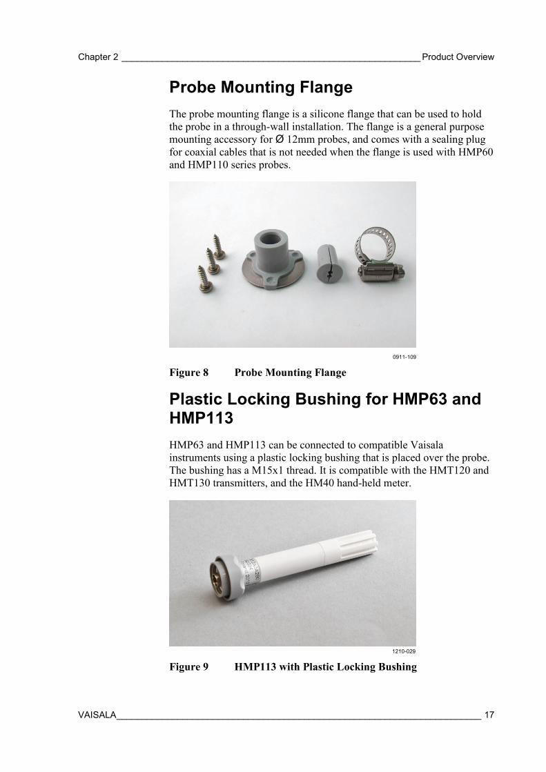
Probe Mounting Flange The probe mounting flange is a silicone flange that can be used to hold the probe in a through-wall installation. The flange is a general purpose mounting accessory for Ø 12mm probes, and comes with a sealing plug for coaxial cables that is not needed when the flange is used with HMP60 and HMP110 series probes.
0911-109
Figure 8 Probe Mounting Flange
Plastic Locking Bushing for HMP63 and HMP113 HMP63 and HMP113 can be connected to compatible Vaisala instruments using a plastic locking bushing that is placed over the probe. The bushing has a M15x1 thread. It is compatible with the HMT120 and HMT130 transmitters, and the HM40 hand-held meter.
1210-029
Figure 9 HMP113 with Plastic Locking Bushing
User's Guide _______________________________________________________________________
18 ___________________________________________________________________ M211060EN-H
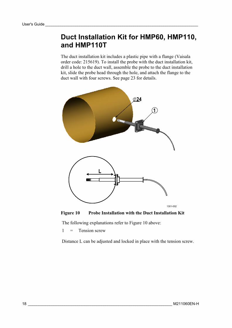
Duct Installation Kit for HMP60, HMP110, and HMP110T The duct installation kit includes a plastic pipe with a flange (Vaisala order code: 215619). To install the probe with the duct installation kit, drill a hole to the duct wall, assemble the probe to the duct installation kit, slide the probe head through the hole, and attach the flange to the duct wall with four screws. See page 23 for details.
1301-002
Figure 10 Probe Installation with the Duct Installation Kit
The following explanations refer to Figure 10 above:
1 = Tension screw Distance L can be adjusted and locked in place with the tension screw.
Chapter 2 ___________________________________________________________ Product Overview
VAISALA ________________________________________________________________________ 19
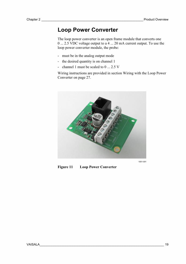
Loop Power Converter The loop power converter is an open frame module that converts one 0 ... 2.5 VDC voltage output to a 4 ... 20 mA current output. To use the loop power converter module, the probe:
- must be in the analog output mode - the desired quantity is on channel 1 - channel 1 must be scaled to 0 ... 2.5 V
Wiring instructions are provided in section Wiring with the Loop Power Converter on page 27.
1001-001
Figure 11 Loop Power Converter
User's Guide _______________________________________________________________________
20 ___________________________________________________________________ M211060EN-H
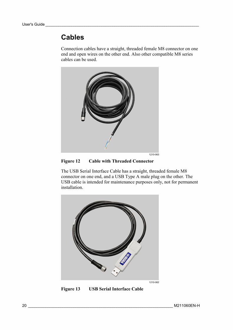
Cables Connection cables have a straight, threaded female M8 connector on one end and open wires on the other end. Also other compatible M8 series cables can be used.
1210-063
Figure 12 Cable with Threaded Connector
The USB Serial Interface Cable has a straight, threaded female M8 connector on one end, and a USB Type A male plug on the other. The USB cable is intended for maintenance purposes only, not for permanent installation.
1210-062
Figure 13 USB Serial Interface Cable
Chapter 3 ________________________________________________________________ Installation
VAISALA ________________________________________________________________________ 21
CHAPTER 3
INSTALLATION
This chapter provides you with information that is intended to help you install the HMP60 and HMP110 series probes.
NOTE Before you connect an HMP60 or HMP110 series probe to a device, it is recommended to power off the device.
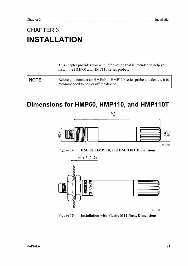
Dimensions for HMP60, HMP110, and HMP110T
0912-103
Figure 14 HMP60, HMP110, and HMP110T Dimensions
0912-102
Figure 15 Installation with Plastic M12 Nuts, Dimensions
User's Guide _______________________________________________________________________
22 ___________________________________________________________________ M211060EN-H
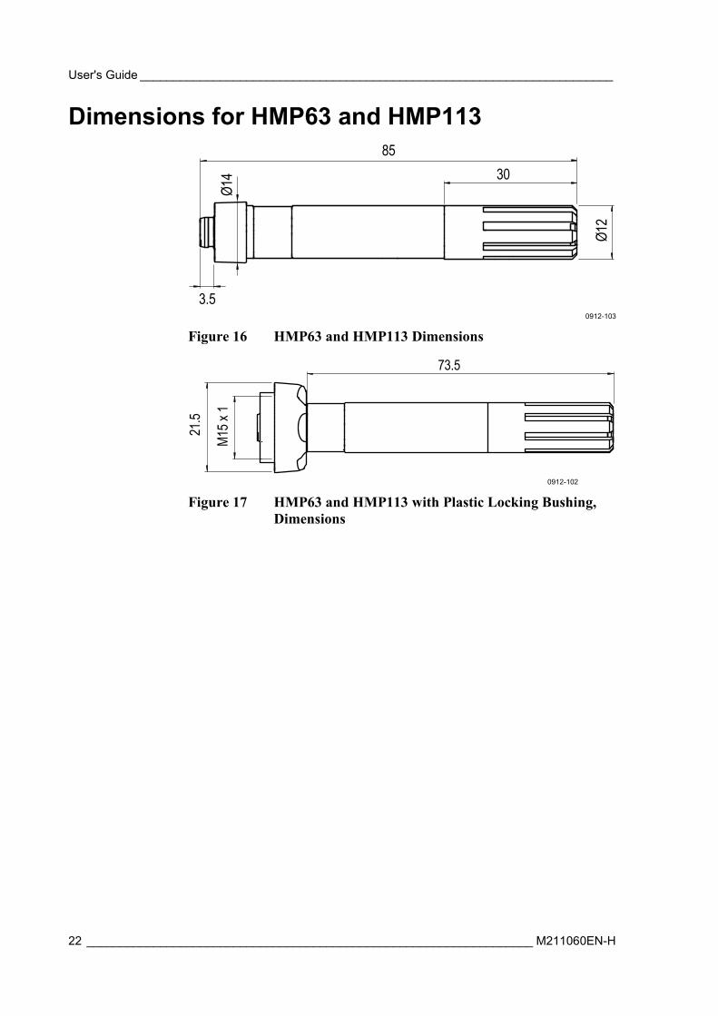
Dimensions for HMP63 and HMP113
0912-103
Figure 16 HMP63 and HMP113 Dimensions
0912-102
Figure 17 HMP63 and HMP113 with Plastic Locking Bushing, Dimensions
85
Ø12
30
Ø14
3.5
M15x
1
73.5
21.5
Chapter 3 ________________________________________________________________ Installation
VAISALA ________________________________________________________________________ 23
Mounting the HMP60, HMP110, and HMP110T Probes
HMP60, HMP110, and HMP110T are designed to be mounted from the M12 thread on the probe body or from the smooth part of the probe body. For a convenient installation, use the optional installation accessories:
- Use the plastic mounting nuts to hold the probe in a through-wall installation.
- Use the probe mounting clamp to hold the probe on a wall.
- Use the probe mounting flange to hold the probe in a through-wall installation.
NOTE Avoid placing the probe in a place where condensation can run onto the sensor.
Probe Assembly with Duct Installation Kit
0505-177
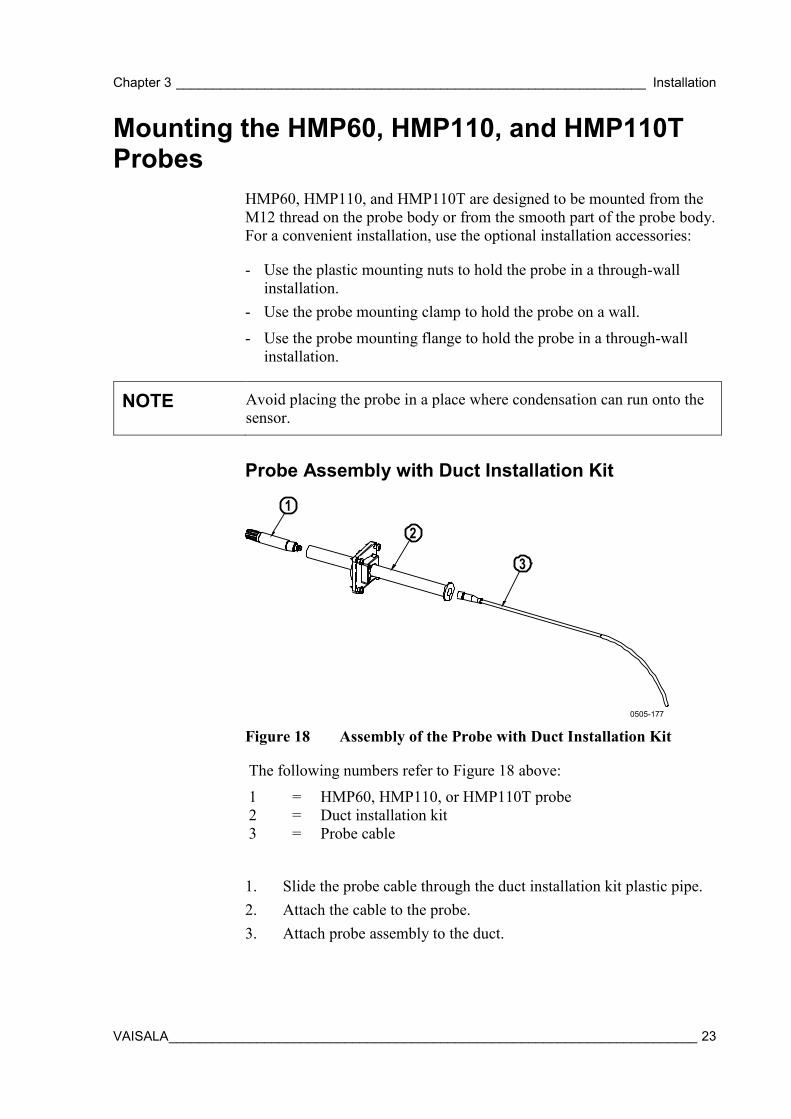
Figure 18 Assembly of the Probe with Duct Installation Kit
The following numbers refer to Figure 18 above:
1 = HMP60, HMP110, or HMP110T probe 2 = Duct installation kit 3 = Probe cable
1. Slide the probe cable through the duct installation kit plastic pipe. 2. Attach the cable to the probe. 3. Attach probe assembly to the duct.
2
1
3
User's Guide _______________________________________________________________________
24 ___________________________________________________________________ M211060EN-H
Drilling Instructions for Duct Installation Kit
0505-178
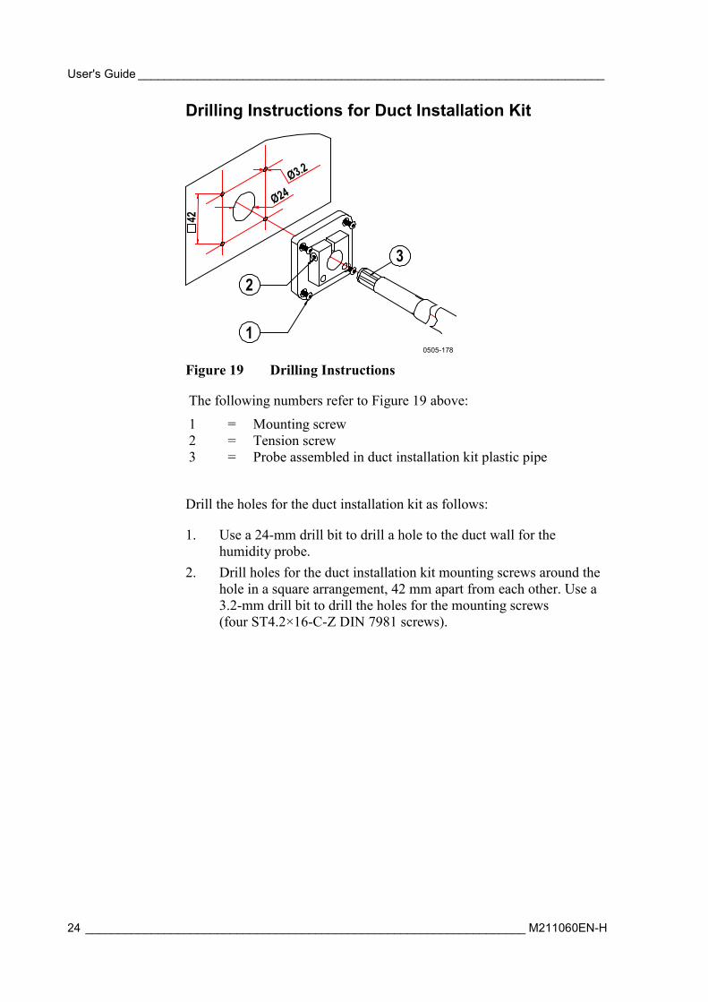
Figure 19 Drilling Instructions
The following numbers refer to Figure 19 above:
1 = Mounting screw 2 = Tension screw 3 = Probe assembled in duct installation kit plastic pipe
Drill the holes for the duct installation kit as follows:
1. Use a 24-mm drill bit to drill a hole to the duct wall for the humidity probe.
2. Drill holes for the duct installation kit mounting screws around the hole in a square arrangement, 42 mm apart from each other. Use a 3.2-mm drill bit to drill the holes for the mounting screws (four ST4.2×16-C-Z DIN 7981 screws).
42
1
23
Ø24Ø3.2
Chapter 3 ________________________________________________________________ Installation
VAISALA ________________________________________________________________________ 25
Mounting the HMP63 and HMP113 Probes HMP63 and HMP113 probes do not have a thread on the probe body. For a convenient installation, use the optional installation accessories:
- Use the probe mounting clamp to hold the probe on a wall.
- Use the probe mounting flange to hold the probe in a through-wall installation.
- If you are using the probe with a HMT120, HMT130, or HM40 hand-held meter, use the plastic locking bushing.
For information on these accessories, see section Installation Accessories (Optional) on page 15.
NOTE Avoid placing the probe in a place where condensation can run onto the sensor.
User's Guide _______________________________________________________________________
26 ___________________________________________________________________ M211060EN-H
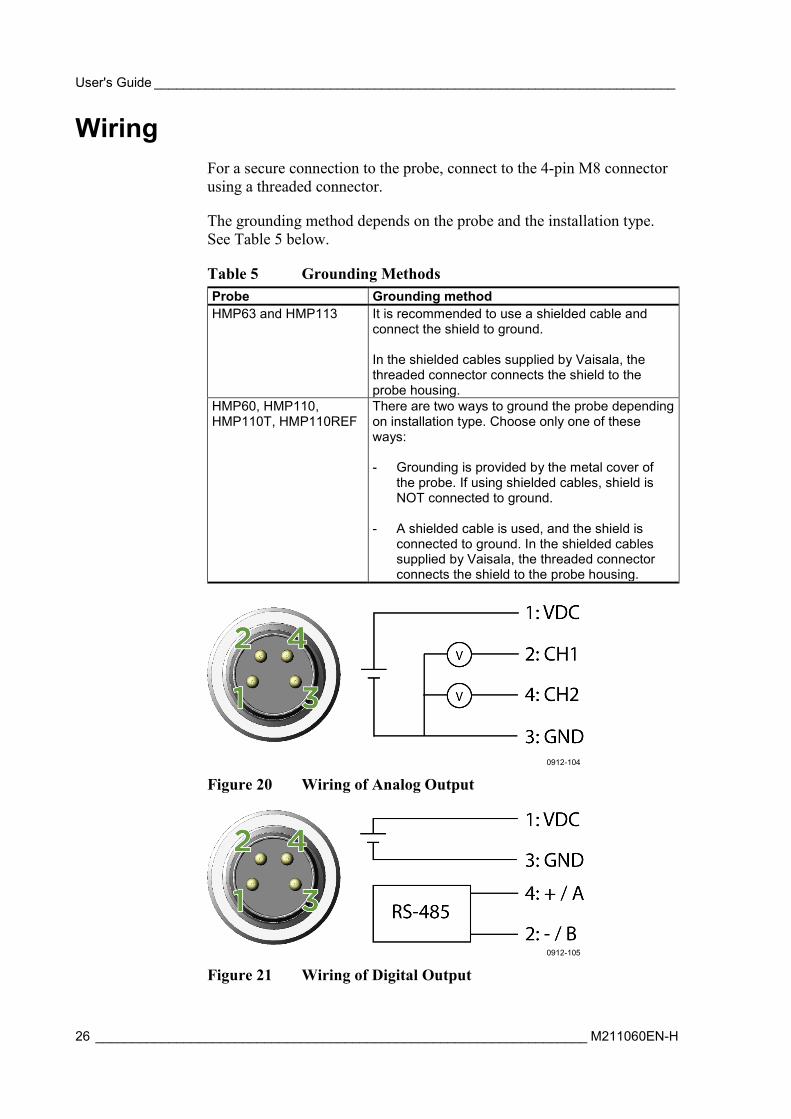
Wiring For a secure connection to the probe, connect to the 4-pin M8 connector using a threaded connector.
The grounding method depends on the probe and the installation type. See Table 5 below.
Table 5 Grounding Methods Probe Grounding method HMP63 and HMP113 It is recommended to use a shielded cable and
connect the shield to ground. In the shielded cables supplied by Vaisala, the threaded connector connects the shield to the probe housing.
HMP60, HMP110, HMP110T, HMP110REF
There are two ways to ground the probe depending on installation type. Choose only one of these ways: - Grounding is provided by the metal cover of
the probe. If using shielded cables, shield is NOT connected to ground.
- A shielded cable is used, and the shield is connected to ground. In the shielded cables supplied by Vaisala, the threaded connector connects the shield to the probe housing.
0912-104
Figure 20 Wiring of Analog Output
0912-105
Figure 21 Wiring of Digital Output
Chapter 3 ________________________________________________________________ Installation
VAISALA ________________________________________________________________________ 27
Table 6 Pinout of the Probe Connector Pin HMP60 / HMP63 / HMP110 analog /
HMP113 / HMP110T HMP110REF / HMP110 digital
Wire color
1 5 ... 28 VDC (Vout 0 ...1 / 0 ... 2.5 V) 8 ... 28 VDC (Vout 0 ... 5 / 1 ... 5 V)
5 ... 28 VDC Brown
2 Channel 1: RH / Td / T 0 ... 1 / 2.5 / 5 V, 1 ... 5 V
RS485: - / B White
3 GND / AGND GND Blue 4 Channel 2: RH / Td / T
0 ... 1 / 2.5 / 5 V, 1 ... 5 V * RS485: + / A Black
* HMP110T has no output on channel 2.
Wiring Multiple Digital Devices The maximum number of HMP60/HMP110 probes that can be connected to a system over the RS-485 interface is 32 when the communication speed is 19200 bps or lower. RS-485 termination must not be used with HMP60/HMP110 series probes.
NOTE Connecting other devices can decrease the maximum number of HMP60/HMP110 probes. If other devices require the use of termination, HMP60/HMP110 probes must be connected using an RS-485 repeater.
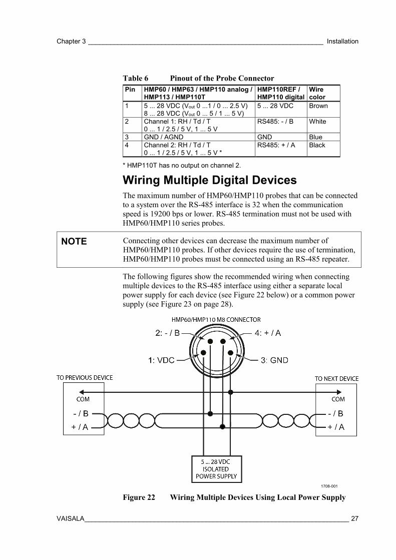
The following figures show the recommended wiring when connecting multiple devices to the RS-485 interface using either a separate local power supply for each device (see Figure 22 below) or a common power supply (see Figure 23 on page 28).
1708-001
Figure 22 Wiring Multiple Devices Using Local Power Supply
User's Guide _______________________________________________________________________
28 ___________________________________________________________________ M211060EN-H
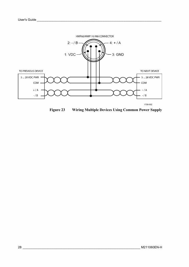
1708-002
Figure 23 Wiring Multiple Devices Using Common Power Supply
Chapter 3 ________________________________________________________________ Installation
VAISALA ________________________________________________________________________ 29
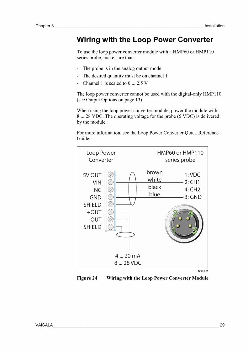
Wiring with the Loop Power Converter To use the loop power converter module with a HMP60 or HMP110 series probe, make sure that:
- The probe is in the analog output mode - The desired quantity must be on channel 1 - Channel 1 is scaled to 0 ... 2.5 V
The loop power converter cannot be used with the digital-only HMP110 (see Output Options on page 13).
When using the loop power converter module, power the module with 8 ... 28 VDC. The operating voltage for the probe (5 VDC) is delivered by the module.
For more information, see the Loop Power Converter Quick Reference Guide.
1210-031
Figure 24 Wiring with the Loop Power Converter Module
User's Guide _______________________________________________________________________
30 ___________________________________________________________________ M211060EN-H
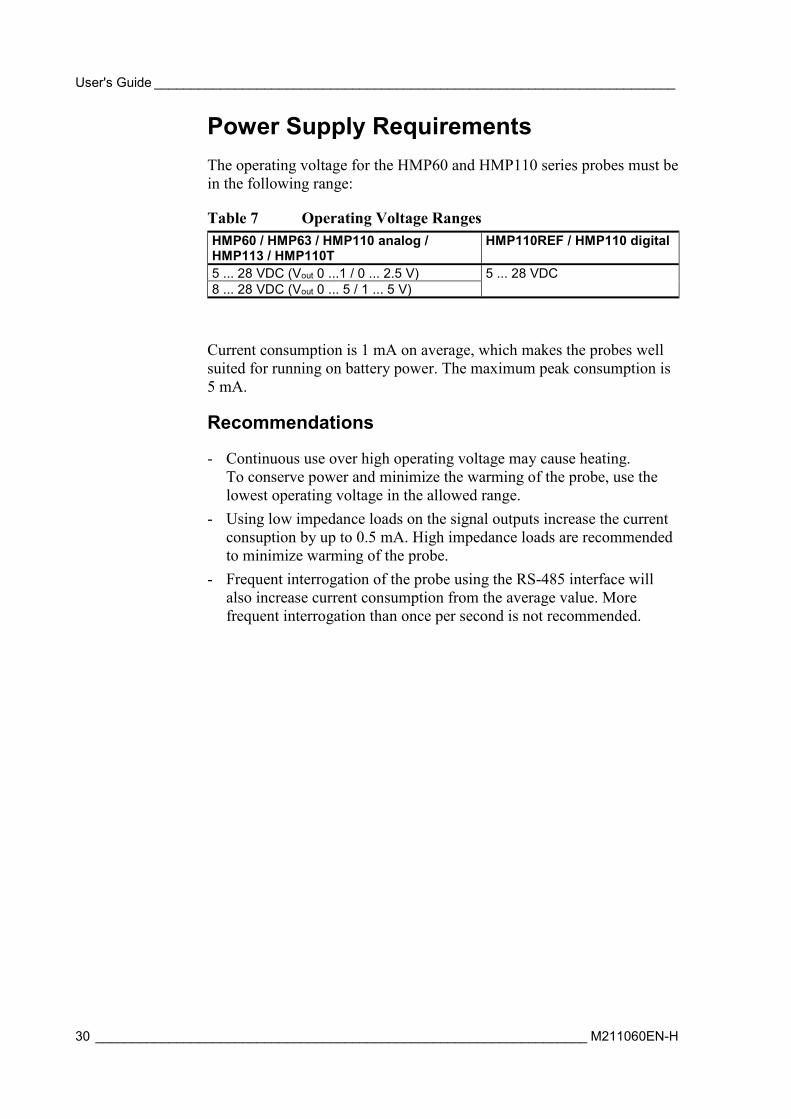
Power Supply Requirements The operating voltage for the HMP60 and HMP110 series probes must be in the following range:
Table 7 Operating Voltage Ranges HMP60 / HMP63 / HMP110 analog / HMP113 / HMP110T
HMP110REF / HMP110 digital
5 ... 28 VDC (Vout 0 ...1 / 0 ... 2.5 V) 5 ... 28 VDC 8 ... 28 VDC (Vout 0 ... 5 / 1 ... 5 V)
Current consumption is 1 mA on average, which makes the probes well suited for running on battery power. The maximum peak consumption is 5 mA.
Recommendations
- Continuous use over high operating voltage may cause heating. To conserve power and minimize the warming of the probe, use the lowest operating voltage in the allowed range.
- Using low impedance loads on the signal outputs increase the current consuption by up to 0.5 mA. High impedance loads are recommended to minimize warming of the probe.
- Frequent interrogation of the probe using the RS-485 interface will also increase current consumption from the average value. More frequent interrogation than once per second is not recommended.
Chapter 4 _________________________________________________________________ Operation
VAISALA ________________________________________________________________________ 31
CHAPTER 4
OPERATION
This chapter contains information that is needed to operate the HMP60 and HMP110 series probes.
Getting Started
NOTE Before you connect an HMP60 or HMP110 series probe to a device, it is recommended to power off the device.
When the probe is connected to a power supply, there is a delay as the probe starts up and the analog output stabilizes. The delay depends on the output type, and on the operating voltage that is supplied to the probe:
- Probes with analog output: - 4 s at operating voltage 13.5 ... 16.5 VDC - 2 s at other valid operating voltages
- Probes with digital output: 1 s
Serial Line Communication
NOTE In analog probes, serial line communication is intended for service use only.
HMP60 and HMP110 series probes support two-wire RS-485 communication. The RS-485 interface is non-isolated and offers a maximum communications rate of 57600 bits/s.
There is no internal termination for the RS-485 on the probe. Use of termination resistors is not recommended. If the resistors are used, the possible increase in current consumption should be taken into account.
Connecting to the Serial Interface The connection to the serial interface is via the 4-pin connector on the probe: see Wiring on page 26.
User's Guide _______________________________________________________________________
32 ___________________________________________________________________ M211060EN-H
For temporary use of the serial interface (for example, calibration), you can use the optional USB cable (Vaisala order code: 219690). Before you can use the USB cable, you must install the provided USB driver on your PC: see Installing the Driver for the USB Cable on page 32.
NOTE The Vaisala USB cable is not designed for permanent installations. When using the USB cable, no separate power unit is needed. The probe is powered through the USB port.
For permanent interfacing to a host system, use a shielded cable with a threaded connector. For a list of available cables,see Options and Accessories on page 74. The probe does not echo typed characters back to the terminal screen. To see the commands you type, you need to enable the "local echo" setting in your terminal program.
A new command cannot be received while the probe is sending data out. Wait until the instrument has completed its response before entering the next command.
Table 8 Default Serial Communication Settings Parameter Value Baud rate 19200 Parity None Data bits 8 Stop bits 1 Flow control None
You can change the serial settings and operate in RUN, STOP, POLL and MODBUS modes.
After power-up the probe (in STOP mode) outputs the software version and the command prompt.
- In RUN mode, a measurement output starts immediately after power-up.
- In POLL mode, the probe does not output anything after power-up. It must be accessed with an addressed command.
- In MODBUS mode, the probe does not output anything after power-up: serial line commands are not in use and the probe must be used with the Modbus protocol. For instructions on returning to serial mode, see Accessing Serial Line Command Interface (RS-485 Mode) from Analog or Modbus Mode on page 36.
For a description of the modes and the SMODE command that is used to change the mode, see section Set Serial Interface Mode on page 44.

Chapter 4 _________________________________________________________________ Operation
VAISALA ________________________________________________________________________ 33
Installing the Driver for the USB Cable Before taking the USB cable into use, you must install the provided USB driver on your PC. When installing the driver, you must acknowledge any security prompts that may appear.
1. Check that the USB cable is not connected. Disconnect the cable if you have already connected it.
2. Insert the media that came with the cable, or download the latest driver from www.vaisala.com/software.
3. Execute the USB driver installation program (setup.exe), and accept the installation defaults. The installation of the driver may take several minutes.
4. After the driver has been installed, connect the USB cable to a USB port on your PC. Windows will detect the new device, and use the driver automatically.
5. The installation has reserved a COM port for the cable. Verify the port number, and the status of the cable, using the Vaisala USB Instrument Finder program that has been installed in the Windows Start menu. The reserved ports are also visible in the Ports section of the Windows Device Manager.
Remember to use the correct port in the settings of your terminal program. Windows will recognize each individual cable as a different device, and reserve a new COM port.
There is no reason to uninstall the driver for normal use. However, if you wish to remove the driver files and all Vaisala USB cable devices, you can do so by uninstalling the entry for Vaisala USB Instrument Driver from the Programs and Features menu in the Windows Control Panel. In Windows XP and earlier Windows versions the menu is called Add or Remove Programs.
User's Guide _______________________________________________________________________
34 ___________________________________________________________________ M211060EN-H
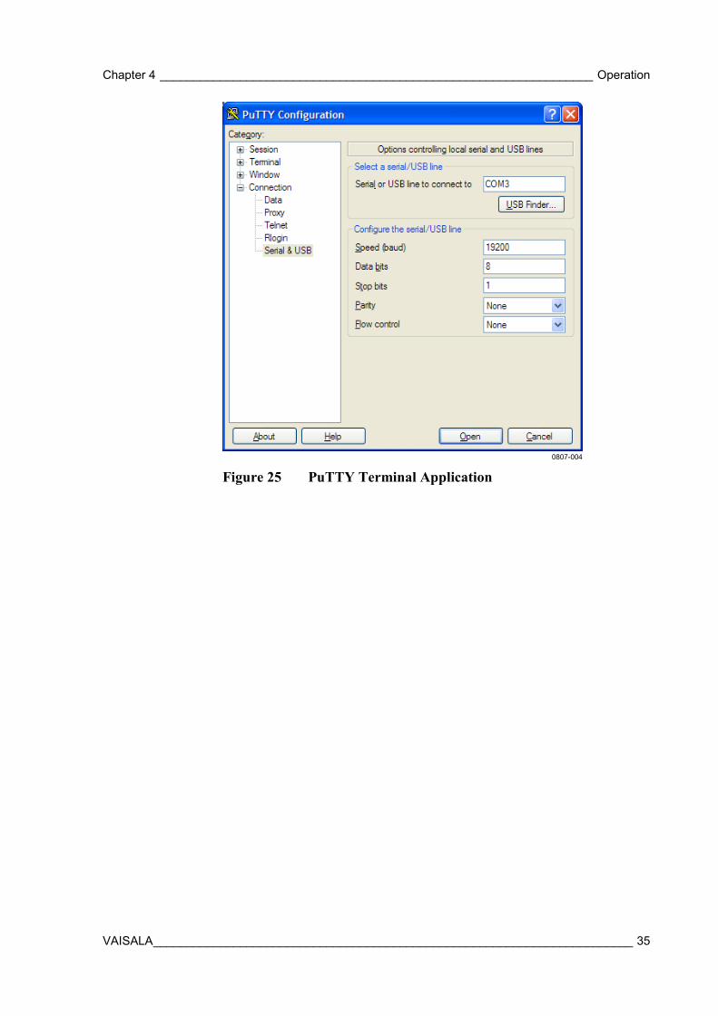
Terminal Application Settings for Digital Probes The steps below describe how to connect to digital probes using the PuTTY terminal application for Windows (available for download at http://www.vaisala.com/software) and the USB serial interface.
If you have an analog probe, you can still connect to the serial line by following the instructions in section Accessing Serial Line Command Interface (RS-485 Mode) from Analog or Modbus Mode on page 36.
1. Connect the USB serial interface cable between your PC and the probe.
2. Start the PuTTY application. 3. Select the Serial settings category, and check that the correct COM
port is selected in the Serial line to connect to field. You can check which port the USB cable is using with the Vaisala USB Instrument Finder program that has been installed in the Windows Start menu.
4. Check that the other serial settings are correct for your connection, and change if necessary. Refer to Table 8 on page 32 for the default serial line settings of the probe.
5. Click the Open button to open the connection window and start using the serial line. If PuTTY is unable to open the serial port you selected, it will show you an error message instead. If this happens, restart PuTTY and check the settings.
6. You may need to adjust the Local echo setting in the Terminal category to see what you are typing on the serial line. To access the configuration screen while a session is running, click the right mouse button over the session window, and select Change Settings... from the pop-up menu.
If the probe is in Modbus mode, to access the serial port command interface, follow the instructions in Accessing Serial Line Command Interface (RS-485 Mode) from Analog or Modbus Mode on page 36.
Chapter 4 _________________________________________________________________ Operation
VAISALA ________________________________________________________________________ 35
0807-004
Figure 25 PuTTY Terminal Application
User's Guide _______________________________________________________________________
36 ___________________________________________________________________ M211060EN-H
Accessing Serial Line Command Interface (RS-485 Mode) from Analog or Modbus Mode Follow the steps below to connect to the serial line when the probe is in analog or Modbus mode, or if you have entered incorrect communication settings, for example, with Modbus configuration registers and the settings need to be restored using the serial interface. You must use the Vaisala USB cable (Vaisala order code: 219690) in this case.
1. Connect the USB cable to the PC and install the driver, if necessary. Do not connect the cable to the probe yet.
2. Open the terminal program and open a connection to the corresponding COM port using the default settings 19200, 8, N, 1, no flow control.
3. Select the Serial settings category, and check that the correct COM port is selected in the Serial line to connect to field. You can check which port the USB cable is using with the Vaisala USB Instrument Finder program that has been installed in the Windows Start menu.
4. Click the Open button to open the connection window and start using the serial line.
5. Keep the Enter key pressed down and connect the other end of the USB cable to the probe. This will cause the probe to start in RS-485 mode, using the default serial settings. You can now use the probe with the terminal program (for information on available serial commands, see List of Serial Commands on page 39).
6. To prevent the analog or Modbus mode from being restored on the next power-up, select a different serial mode with the smode command (see Set Serial Interface Mode on page 44).
7. To switch back to analog mode or Modbus mode from the serial mode, use the smode analog command or the smode modbus command to select analog or Modbus mode. Reset or power cycle the probe to restart in the selected mode.
NOTE The probe cannot be used with the MI70 hand-held indicator when the probe is in analog mode. To use the probe with MI70, enable the serial mode as instructed above.
Chapter 4 _________________________________________________________________ Operation
VAISALA ________________________________________________________________________ 37
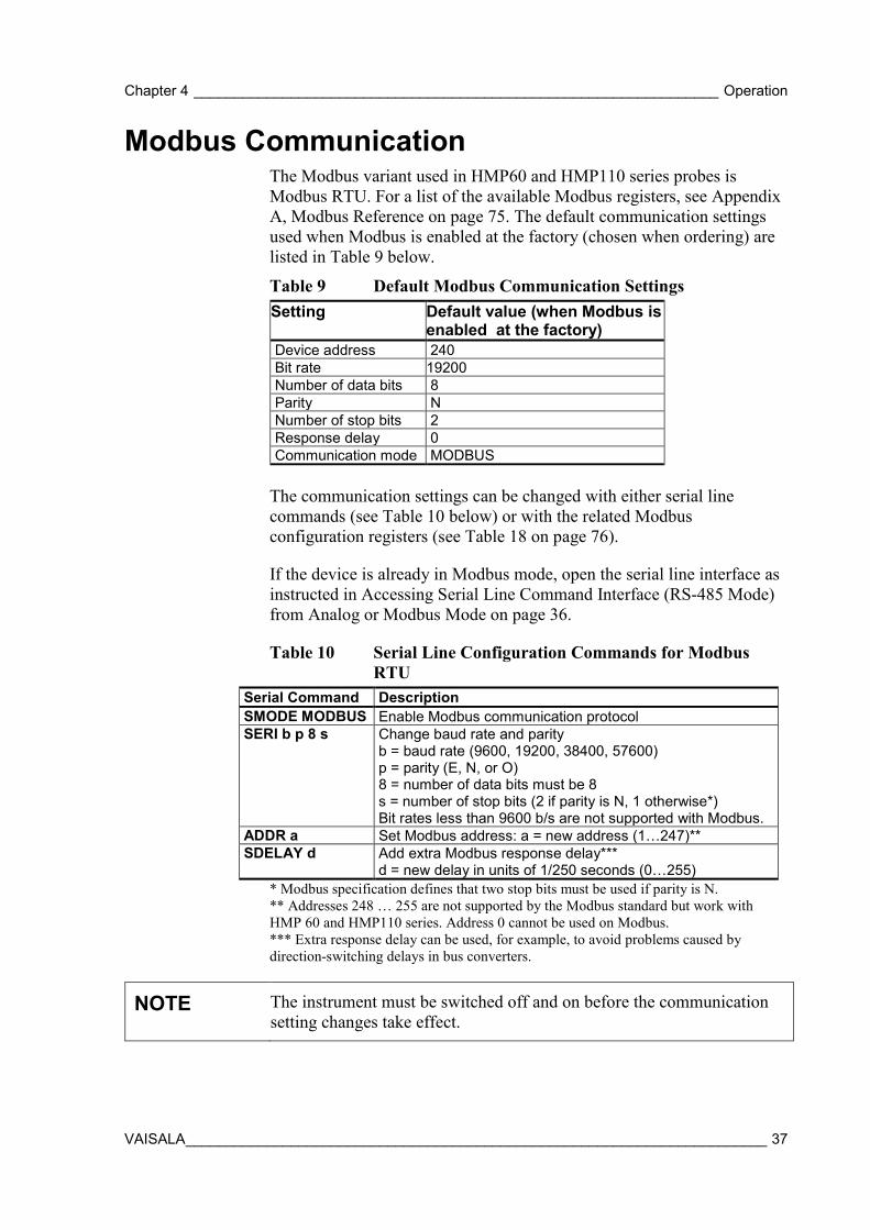
Modbus Communication The Modbus variant used in HMP60 and HMP110 series probes is Modbus RTU. For a list of the available Modbus registers, see Appendix A, Modbus Reference on page 75. The default communication settings used when Modbus is enabled at the factory (chosen when ordering) are listed in Table 9 below.
Table 9 Default Modbus Communication Settings Setting Default value (when Modbus is
enabled at the factory) Device address 240 Bit rate 19200 Number of data bits 8 Parity N Number of stop bits 2 Response delay 0 Communication mode MODBUS
The communication settings can be changed with either serial line commands (see Table 10 below) or with the related Modbus configuration registers (see Table 18 on page 76).
If the device is already in Modbus mode, open the serial line interface as instructed in Accessing Serial Line Command Interface (RS-485 Mode) from Analog or Modbus Mode on page 36.
Table 10 Serial Line Configuration Commands for Modbus RTU
Serial Command Description SMODE MODBUS Enable Modbus communication protocol SERI b p 8 s Change baud rate and parity
b = baud rate (9600, 19200, 38400, 57600) p = parity (E, N, or O) 8 = number of data bits must be 8 s = number of stop bits (2 if parity is N, 1 otherwise*) Bit rates less than 9600 b/s are not supported with Modbus.
ADDR a Set Modbus address: a = new address (1…247)** SDELAY d Add extra Modbus response delay***
d = new delay in units of 1/250 seconds (0…255) * Modbus specification defines that two stop bits must be used if parity is N. ** Addresses 248 … 255 are not supported by the Modbus standard but work with HMP 60 and HMP110 series. Address 0 cannot be used on Modbus. *** Extra response delay can be used, for example, to avoid problems caused by direction-switching delays in bus converters.
NOTE The instrument must be switched off and on before the communication setting changes take effect.
User's Guide _______________________________________________________________________
38 ___________________________________________________________________ M211060EN-H
Using Multiple Devices over RS-485 When you use HMP60/HMP110 series probes for Modbus communication over the RS-485 interface, the maximum number of HMP60/HMP110 probes that can be connected to a system is 32 (with a communication speed of 19200 bps or lower).
NOTE RS-485 termination must not be used with HMP60/HMP110 series probes.
NOTE Connecting other devices can decrease the maximum number of HMP60/HMP110 probes that can be connected. If other devices require the use of termination, HMP60/HMP110 series probes must be connected using an RS-485 repeater.
For information on the recommended wiring when connecting multiple devices, see Wiring Multiple Digital Devices on page 27.
Chapter 4 _________________________________________________________________ Operation
VAISALA ________________________________________________________________________ 39
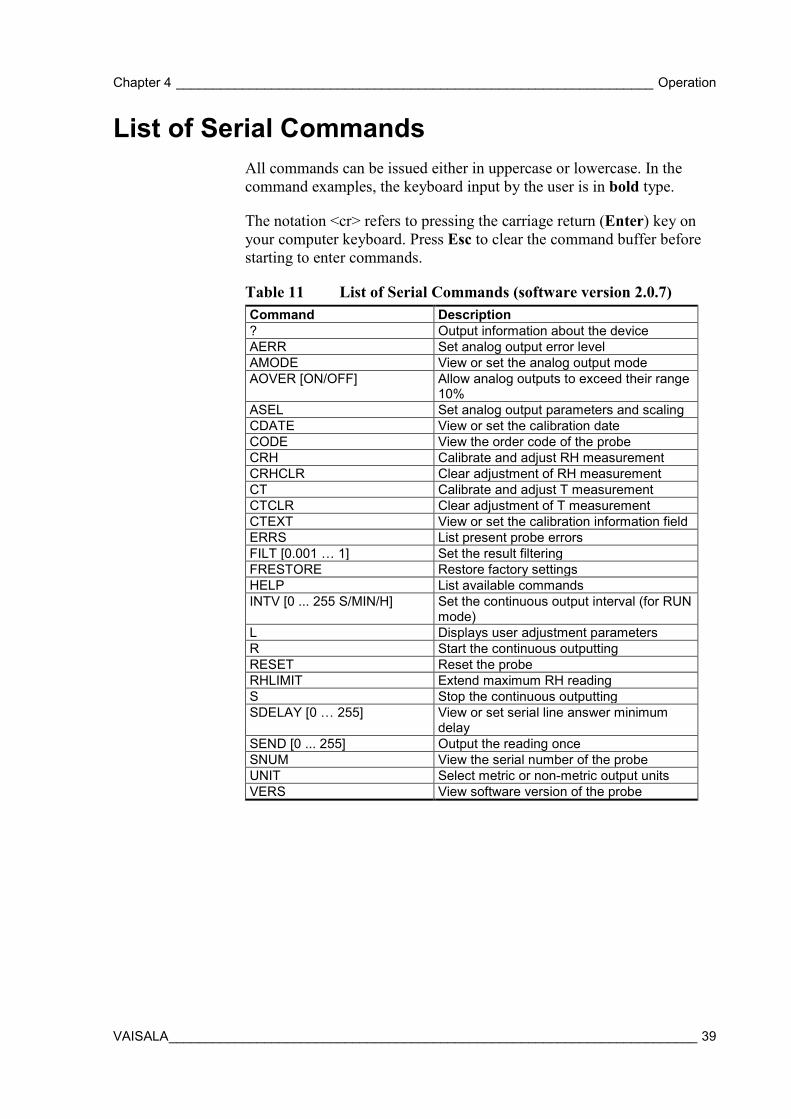
List of Serial Commands All commands can be issued either in uppercase or lowercase. In the command examples, the keyboard input by the user is in bold type.
The notation <cr> refers to pressing the carriage return (Enter) key on your computer keyboard. Press Esc to clear the command buffer before starting to enter commands.
Table 11 List of Serial Commands (software version 2.0.7) Command Description ? Output information about the device AERR Set analog output error level AMODE View or set the analog output mode AOVER [ON/OFF] Allow analog outputs to exceed their range
10% ASEL Set analog output parameters and scaling CDATE View or set the calibration date CODE View the order code of the probe CRH Calibrate and adjust RH measurement CRHCLR Clear adjustment of RH measurement CT Calibrate and adjust T measurement CTCLR Clear adjustment of T measurement CTEXT View or set the calibration information field ERRS List present probe errors FILT [0.001 … 1] Set the result filtering FRESTORE Restore factory settings HELP List available commands INTV [0 ... 255 S/MIN/H] Set the continuous output interval (for RUN
mode) L Displays user adjustment parameters R Start the continuous outputting RESET Reset the probe RHLIMIT Extend maximum RH reading S Stop the continuous outputting SDELAY [0 … 255] View or set serial line answer minimum
delay SEND [0 ... 255] Output the reading once SNUM View the serial number of the probe UNIT Select metric or non-metric output units VERS View software version of the probe
User's Guide _______________________________________________________________________
40 ___________________________________________________________________ M211060EN-H
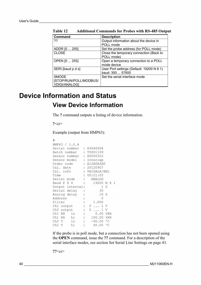
Table 12 Additional Commands for Probes with RS-485 Output Command Description ?? Output information about the device in
POLL mode ADDR [0 ... 255] Set the probe address (for POLL mode) CLOSE Close the temporary connection (Back to
POLL mode) OPEN [0 ... 255] Open a temporary connection to a POLL
mode device SERI [baud p d s] User Port settings (Default: 19200 N 8 1)
baud: 300 ... 57600 SMODE [STOP/RUN/POLL/MODBUS/VDIGI/ANALOG]
Set the serial interface mode
Device Information and Status View Device Information The ? command outputs a listing of device information.
?<cr>
Example (output from HMP63):
? HMP63 / 1.0.4 Serial number : H3640004 Batch number : T0001109 Sensor number : H0000322 Sensor model : Intercap Order code : A12A0A2B0 Cal. date : 20120907 Cal. info : VAISALA/HEL Time : 00:21:05 Serial mode : ANALOG Baud P D S : 19200 N 8 1 Output interval: 1 S Serial delay : 30 Analog delay : 10 S Address : 0 Filter : 1.000 Ch1 output : 0 ... 1 V Ch2 output : 0 ... 1 V Ch1 RH lo : 0.00 %RH Ch1 RH hi : 100.00 %RH Ch2 T lo : -40.00 'C Ch2 T hi : 60.00 'C If the probe is in poll mode, but a connection has not been opened using the OPEN command, issue the ?? command. For a description of the serial interface modes, see section Set Serial Line Settings on page 43.
??<cr>
Chapter 4 _________________________________________________________________ Operation
VAISALA ________________________________________________________________________ 41
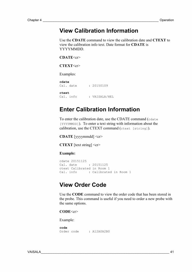
View Calibration Information Use the CDATE command to view the calibration date and CTEXT to view the calibration info text. Date format for CDATE is YYYYMMDD.
CDATE<cr>
CTEXT<cr>
Examples:
cdate Cal. date : 20150109 ctext Cal. info : VAISALA/HEL
Enter Calibration Information To enter the calibration date, use the CDATE command (cdate [YYYYMMDD]). To enter a text string with information about the calibration, use the CTEXT command (ctext [string]).
CDATE [yyyymmdd] <cr>
CTEXT [text string] <cr>
Example:
cdate 20151125 Cal. date : 20151125 ctext Calibrated in Room 1 Cal. info : Calibrated in Room 1
View Order Code Use the CODE command to view the order code that has been stored in the probe. This command is useful if you need to order a new probe with the same options.
CODE<cr>
Example:
code Order code : A12A0A2B0
User's Guide _______________________________________________________________________
42 ___________________________________________________________________ M211060EN-H
View Serial Number Use the SNUM command to view the serial number of the probe.
SNUM<cr>
Example:
snum Serial number : H3640004
View Software Version Use the VERS command to display the software version of the probe.
VERS<cr>
Example:
vers HMP63 / 1.0.4
Serial Line Output Commands Start Measurement Output Use the R command to start the continuous outputting of measurement values as an ASCII text string to the serial line.
For HMP60 and HMP110, the output always includes readings for temperature, RH and Td. For HMP110T, the output includes only temperature.
R<cr>
Example (HMP60 and HMP110):
r T= 22.6 'C RH= 22.8 %RH Td= 0.3 'C T= 22.6 'C RH= 22.5 %RH Td= 0.2 'C T= 22.6 'C RH= 22.5 %RH Td= 0.2 'C … Example (HMP110T):
r T= 22.6 'C T= 22.6 'C T= 22.6 'C …
Chapter 4 _________________________________________________________________ Operation
VAISALA ________________________________________________________________________ 43
Outputting the results continues in intervals issued with the command INTV. You can stop the output by entering the S command.
Stop Measurement Output Use the S command or press the Esc key to stop the continuous measurement output.
S<cr>
Output the Measurement Message Once Use the SEND command to output the measurement values once. If the probe is in POLL mode and the line is not open for commands, specify the address of the probe to receive the measurement message.
SEND [aaa]<cr>
where
aaa = Address of the probe, range 0 ... 255. Set with the ADDR command.
Example (probe in STOP mode, no address needed):
send T= 22.7 'C RH= 20.0 %RH Td= -1.5 'C Example (probe in POLL mode, with address 10):
send 10 T= 22.8 'C RH= 20.1 %RH Td= -1.3 'C
Configuring Serial Line Operation Set Serial Line Settings Use the SERI command to show or set the serial line settings. The new settings will be taken into use when the probe is reset or powered up.
SERI [b p d s]<cr> where
b = baud rate (300, 600, 1200, 2400, 4800, 9600, 19200, 38400, 57600)
p = parity (n = none, e = even, o = odd) d = data bits (7 or 8) s = stop bits (1 or 2)
User's Guide _______________________________________________________________________
44 ___________________________________________________________________ M211060EN-H
Example (shows default settings):7
seri Baud P D S : 19200 N 8 1
Set Serial Interface Mode Use the SMODE command to set the operation mode of the serial interface. The new mode is applied when probe is reset.
SMODE [xxx]<cr>
where
xxx = Operation mode of the serial interface. See Table 13 below. Table 13 Serial Interface Modes Mode Description STOP Probe outputs only when a command is issued. Any command
can be used. RUN Probe automatically outputs measurement messages on the
serial line. Only command S or the Esc key can be used to stop the output.
POLL Probe outputs only when a command is issued. Probes communicate one at a time when the specific address is called on the serial line, which is useful when more than one probe is connected to one serial bus. Any command can be used after the line has been opened using the OPEN command. See descriptions of the commands ADDR on page 46 and OPEN on page 55.
MODBUS Measurement outputs must be read from the transmitter using the Modbus protocol. For more information on Modbus, see Modbus Communication on page 37 and Appendix A, Modbus Reference on page 75.
VDIGI Special serial interface mode that is only used for interoperability with Vaisala devices such as HMT120, HMT130, and HM40. This mode is set at Vaisala for probes that are ordered for such use.
ANALOG No serial line, analog outputs active. For instructions on how to enter the serial line when in analog mode, see section Accessing Serial Line Command Interface (RS-485 Mode) from Analog or Modbus Mode on page 36. Note that analog output channels are not available in the digital-only HMP110. See Output Options on page 13.
Example (check current mode): smode Serial mode : STOP ? Example (change mode to POLL mode): smode poll Serial mode : POLL
Chapter 4 _________________________________________________________________ Operation
VAISALA ________________________________________________________________________ 45
NOTE In the RUN mode, the probe may send the measurement data message right as you are typing the S command to stop the sending. Therefore, you may need to repeat the S command. This must be noted especially when designing computer programs to access the probe.
NOTE The digital-only HMP110 probe option cannot be set to analog mode.
Set Output Interval Use the INTV command to show or set the output interval of the serial line measurement messages (applies when R command or RUN mode is used). The shortest output interval is one second. This command has no effect on the operation of the analog output.
INTV [n xxx]<cr>
where
n = Time interval in range 1 ... 255 xxx = time unit = "S", "MIN", or "H" Example:
intv 1 s Value : 1 Unit : S
Set Measurement Filtering Use the FILT command to view or set the speed at which the latest measurement result is integrated into the humidity and temperature readings. The command affects both analog output and serial line output.
FILT [a.aaa]<cr>
where
a.aaa = Range 0.001 ... 1.0. 1.0 = No filtering, latest measurement is output without averaging 0.5 = Average of last two measurements 0.1 = Average of approximately 16 measurements
Example (default setting, no filtering):
User's Guide _______________________________________________________________________
46 ___________________________________________________________________ M211060EN-H
filt Filter : 1.000 ?
Example (set filtering to 0.5):
filt 0.5 Filter : 0.500
Set Probe Address Use the ADDR command to view or set the probe address. To operate in the POLL mode, the probe must have an address. If multiple probes share the same serial line, each probe must have a different address.
For a description of the serial interface modes, see section Set Serial Line Settings on page 43.
ADDR [nn]<cr>
where
nn = address (0 ... 255)
Example:
addr Address : 0
Set Serial Interface Delay Use the SDELAY command to view or set the serial interface answer minimum delay.
SDELAY [delay]<cr>
where
delay = Range 0 ... 255. Value corresponds to four milliseconds (for example, 5 = 0.020 second minimum answer delay)
Example:
sdelay Serial delay : 30 sdelay 50 Serial delay : 50
Chapter 4 _________________________________________________________________ Operation
VAISALA ________________________________________________________________________ 47
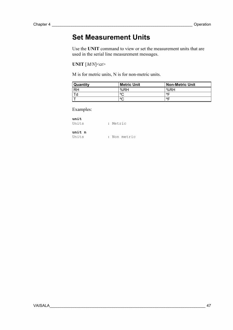
Set Measurement Units Use the UNIT command to view or set the measurement units that are used in the serial line measurement messages.
UNIT [M/N]<cr>
M is for metric units, N is for non-metric units.
Quantity Metric Unit Non-Metric Unit RH %RH %RH Td ºC ºF T ºC ºF
Examples:
unit Units : Metric unit n Units : Non metric
User's Guide _______________________________________________________________________
48 ___________________________________________________________________ M211060EN-H
Calibration Commands Calibrate Humidity Measurement Use the CRH command to perform a one-point or two-point correction to the capacitance measurement of the probe. This command changes the offset and/or gain of the humidity measurement, depending on the calibration and reference:
- one-point calibration with a single < 50 %RH reference will adjust the offset of the capacitance measurement
- one-point calibration with a single > 50 %RH reference will adjust the gain of the capacitance measurement
- two-point calibration will adjust both offset and gain. The first point requires a < 50 %RH humidity reference, the second point must be > 50 %RH. There must also be at least 30 percentage point difference between the references.
CRH [reference]<cr>
This command is not available on the HMP110T.
When performing a one-point calibration, you need to place the probe in the reference humidity and wait for 20 – 40 minutes for the humidity to stabilize. To apply the adjustment, enter the CRH command with the reference %RH as a parameter.
Example: one-point calibration (LiCl reference, 11 %RH):
crh 11 OK Example: one-point calibration with NaCl reference (75 %RH):
crh 75 OK
Giving the command without parameters starts the two-point calibration. Remember to allow the humidity to stabilize for 20 - 40 minutes after changing the reference.
Example: two-point calibration with LiCl (11 %RH) and NaCL (75 %RH) references:
crh RH : 11.2684 1. ref ? 11 Press any key when ready ... RH : 75.0612 2. ref ? 75 OK
Chapter 4 _________________________________________________________________ Operation
VAISALA ________________________________________________________________________ 49
Clear Adjustment of RH Measurement Use the CRHCLR command to clear the adjustment of RH measurement that has been done using the CRH command. This command is not available on the HMP110T.
CRHCLR<cr>
Example: crhclr OK
Calibrate Temperature Measurement Use the CT command to perform a one-point or two-point temperature (T) calibration. One-point calibration adjusts the offset for the measurement, two-point calibration adjusts offset and gain.
CT [reference]<cr>
When performing a one-point calibration, you need to place the probe in a single temperature reference and wait for 20 – 40 minutes for the temperature to stabilize. To apply the adjustment, enter the CT command with the reference temperature as a parameter.
Example: one-point calibration
ct 23.5 OK
Giving the command without parameters starts the two-point calibration. Remember to allow the temperature to stabilize for 20 - 40 minutes after changing the reference. The first reference point must be smaller than the second point, and the difference between the reference points must be more than 30 ºC. To update the measured value while the command is running, press enter without inputting a value.
Example: two-point calibration
ct T : 22.03 Ref1 ? 22 Press any key when ready ... T : 55.12 Ref2 ? 55 OK
User's Guide _______________________________________________________________________
50 ___________________________________________________________________ M211060EN-H
Clear Adjustment of T Measurement Use the CTCLR command to clear the adjustment of temperature measurement that has been done using the CT command.
CTCLR<cr>
Example: ctclr OK
View User Adjustment Parameters Use the L command to view the current user adjustment parameters. This command is useful for checking the currently applied customer calibration.
L<cr>
The output values are as follows:
- Cp offset and gain: capacitance, calibrated using the CRH command - T offset and gain: calibrated using the CT command
Example (shows default values, no user calibration done):
l Cp offset : 0.00000000E+00 Cp gain : 1.00000000E+00 T offset : 0.00000000E+00 T gain : 1.00000000E+00
Chapter 4 _________________________________________________________________ Operation
VAISALA ________________________________________________________________________ 51
Other Commands Set Analog Output Mode Use the AMODE command to show or set the operation mode of the analog output. This command is not in use in the digital-only HMP110 probe option.
AMODE [ch1] [ch2]<cr>
where
ch1
= Analog output mode for channel 1, range 0 ...3. The options are:
0 (0 ... 1 V) 1 (0 ... 2.5 V) 2 (0 ... 5 V) 3 (1 ... 5 V)
ch2 = Analog output mode for channel 2, range 0 ...3. The options are the same as for channel 1.
Example (show current output modes):
amode Ch1 output : 0 ... 1 V Ch2 output : 0 ... 1 V
Example (set channel 1 to 0 ... 1 V and channel 2 to 0 ... 5 V):
amode 0 2 Ch1 output : 0 ... 1 V Ch2 output : 0 ... 5 V
User's Guide _______________________________________________________________________
52 ___________________________________________________________________ M211060EN-H
Set Analog Output Parameters and Scaling Use the ASEL command to show or set the output parameters and scaling of the analog outputs. This command is not in use in the digital-only HMP110 probe option.
ASEL [ch1 ch2] [ch1low ch1high ch2low ch2high]<cr>
where
ch1
= Output parameter for channel 1. The options are: RH = Relative humidity TD = Dewpoint temperature T = Temperature
ch2 = Output parameters for channel 2. The options are same as for channel 1.
ch1low = Low limit for channel 1 output scaling. ch1high = High limit for channel 1 output scaling. ch2low = Low limit for channel 2 output scaling. ch2high = High limit for channel 2 output scaling.
Example (show current output parameters and scaling):
asel ? Ch1 RH lo : 0.00 %RH ? Ch1 RH hi : 100.00 %RH ? Ch2 T lo : -20.00 'C ? Ch2 T hi : 80.00 'C ?
Example (change channel 1 to output dewpoint temperature, adjust scaling to -40 ... 60 °C for channel 1 and to -20 ... 80 °C for channel 2):
asel td t -40 60 -20 80 Ch1 Td lo : -40.00 'C Ch1 Td hi : 60.00 'C Ch2 T lo : -20.00 'C Ch2 T hi : 80.00 'C Example (change channel 1 to output temperature and channel 2 to output relative humidity, adjust scaling for channel 1 to -40 ... 60 °C when prompted):
asel t rh Ch1 T lo : -20.00 'C ? -40 Ch1 T hi : 80.00 'C ? 60 Ch2 RH lo : 0.00 %RH ? Ch2 RH hi : 100.00 %RH ?
Chapter 4 _________________________________________________________________ Operation
VAISALA ________________________________________________________________________ 53
Set Analog Output Error Indication Level If the device is malfunctioning, the analog output is set to a specified level. This overrides the normal measurement output of the channel. The default error level is 0 V, or another value predefined by the customer when ordering the device. You can set the level using the AERR command. This command is not in use in the digital-only HMP110 probe option.
AERR [ch1 ch2] <cr>
where
ch1 = Error level of the analog output for channel 1. The available range depends on the output mode (check with AMODE command).
ch2 = Error level of the analog output for channel 2. The available range depends on the output mode (check with AMODE command).
Example (show present output modes):
amode Ch1 output : 0 ... 1 V Ch2 output : 0 ... 1 V Example (check present analog output error level):
aerr Ch1 error out: 0.000V ? Ch2 error out: 0.000V ? Example (set analog output error level to 1 V on both channels):
aerr 1 1 Ch1 error out: 1.000V ? Ch2 error out: 1.000V ?
NOTE The error output value is displayed only when there are minor electrical faults such as humidity sensor damage. When there is a severe device malfunction, the error output value is not necessarily shown.
User's Guide _______________________________________________________________________
54 ___________________________________________________________________ M211060EN-H
Extend Analog Output Range Use the AOVER command to allow the analog output channels to exceed their specified range by 10%. The scaling of the quantity remains as before; the extra range is used for additional measurement range in the wet end. This command is not in use in the digital-only HMP110 probe option.
AOVER [ON/OFF]<cr>
The following example illustrates how the analog output is affected. Channel 1 outputs Td with voltage output 0 … 5 V (-40 °C … +60 °C). After giving the AOVER ON command, the range is 0 … 5.5 V (-40 °C … +70 °C). Note that the +60 °C Td point is still at 5 V.
Example:
aover on AOVER : ON
Extend Maximum RH Reading With digital output, use the RHLIMIT command to set the maximum RH reading from 100% (default) up to 120%.
With analog output, the RHLIMIT command allows you to extend the high limit of the analog output scaling up to 120%. This command does not change the scaling automatically. To change the scaling, use the ASEL command (see Set Analog Output Parameters and Scaling on page 52).
RHLIMIT [max_rh]<cr>
where
max_rh = Maximum reading of the RH parameter. The possible values are 100.0 … 120.0. The default value is 100.0.
Example (extend the maximum RH reading to 120%):
rhlimit 120 Max. RH % : 120.0 %RH
Chapter 4 _________________________________________________________________ Operation
VAISALA ________________________________________________________________________ 55
Example (on analog output, extend the maximum RH reading to 120% and scale the RH output on channel 2 from (0…1 V) 0...100% to (0…1 V) 0…120%):
rhlimit 120 Max. RH % : 120.0 %RH asel ? Ch1 T lo : -20.00 'C ? Ch1 T hi : 80.00 'C ? Ch2 RH lo : 0.00 %RH ? Ch2 RH hi : 100.00 %RH ? 120
Display Command List Use the HELP command to display a list of the currently available commands.
HELP<cr>
Display the Currently Active Errors Use the ERRS command to display the currently active error codes. For troubleshooting active errors, see Table 14 on page 67.
ERRS<cr>
Example (no active errors):
errs 0000h No errors
Connect to the Probe in POLL Mode Use the OPEN command to connect to a probe that is in POLL mode.
OPEN [aa]<cr>
where
aa = address (0 ... 255)
Example:
open 1 HMP110 1 line opened for operator commands
User's Guide _______________________________________________________________________
56 ___________________________________________________________________ M211060EN-H
Close the Connection in POLL Mode The CLOSE command closes the connection to the probe.
CLOSE<cr>
Example:
close line closed
Reset the Probe Use the RESET command to reset the probe. Upon reset or power-up, the probe enters the serial mode that has been set with the SMODE command.
RESET<cr>
Example (probe set to serial mode STOP, will output probe model and software version at reset):
reset HMP60 / 1.00.0 Example (probe set to serial mode RUN, will start to output measurement messages at reset):
reset T= 23.6 'C RH= 20.2 %RH Td= -0.5 'C T= 23.6 'C RH= 20.2 %RH Td= -0.5 'C T= 23.3 'C RH= 20.2 %RH Td= -0.8 'C ...
Restore Factory Settings Use the FRESTORE command to restore the factory settings to the probe. All user settings, including the user-performed calibration corrections, will be lost. The probe will revert back to the factory calibrated settings.
FRESTORE<cr>
Example:
frestore Factory settings restored
Chapter 5 _______________________________________________________________ Maintenance
VAISALA ________________________________________________________________________ 57
CHAPTER 5
MAINTENANCE
This chapter provides information that is needed in basic maintenance of the HMP60 and HMP110 series probes.
Periodic Maintenance The humidity measurement accuracy of the HMP60 and HMP110 series probes should be calibrated yearly. When calibration indicates that accuracy is not within specification:
- HMP60 and HMP63: change the INTERCAP® sensor. - HMP110 and HMP113: adjust the measurement yourself, or have it
adjusted at a Vaisala Service Center. Light cleaning of the probe, and replacement of the filter should be done only when necessary.
Cleaning The probe body can be wiped clean with a soft, lint-free cloth moistened with mild detergent. Do not use solvents or compressed air.
Note that wiping the membrane filter or stainless steel sintered filter may block its pores and/or deposit residue on the filter. If the filter is heavily contaminated, replace it.
Changing the Filter The filter on the probe should be replaced when it is damaged or dirty.
1. Turn the filter counter-clockwise to loosen it. 2. Remove the filter from the probe. Be careful not to touch the
sensors with the filter. Without the filter in place, the sensors are easily damaged – handle the probe carefully.
3. Install a new filter on the probe, and tighten it so it is finger-tight. Make sure the filter sits straight and meets the threads properly.
New filters can be ordered from Vaisala. For available filters, see section Filter Options on page 14. The order codes of the filters are listed in section Options and Accessories on page 74.
User's Guide _______________________________________________________________________
58 ___________________________________________________________________ M211060EN-H
Calibration Procedure To calibrate your probe, you need a known stable humidity or temperature reference, and a way to read the output of the probe (analog output, serial output, or the MI70 indicator). As a humidity reference you can use, for example, the Vaisala Humidity Calibrator HMK15.
NOTE The probe cannot be used with the MI70 hand-held indicator when the probe is in analog mode. To use the probe with MI70, enable the serial mode as instructed in Accessing Serial Line Command Interface (RS-485 Mode) from Analog or Modbus Mode on page 36. To return to analog mode, use the smode analog serial line command (see Set Serial Interface Mode on page 44).
Refer to chapter Technical Data on page 69 for accuracy specifications of the probes.
1. Connect the power/signal cable or MI70 connection cable to the probe, but do not power it up yet.
2. Remove the filter from the probe and place the probe in the reference environment. For example, you can use a NaCl salt chamber (75 %RH) as the humidity reference.
3. Wait for 20 – 40 minutes for the reading to stabilize. 4. Power up the probe and wait for one minute. 5. Check the measurement reading, and compare it with the reading
that the reference should produce.
Adjustment Procedure Using Serial Line (HMP110 and HMP113)
NOTE If you are adjusting a probe that is in the analog output mode, see section Accessing Serial Line Command Interface (RS-485 Mode) from Analog or Modbus Mode on page 36 for instructions on how to start the probe in RS-485 mode.
One-Point Adjustment of RH Measurement (HMP110 and HMP113) To perform a one-point adjustment to the capacitance measurement of the HMP110 or HMP113 using serial line, you need:
- The Vaisala USB cable (Vaisala order code: 219690)
Chapter 5 _______________________________________________________________ Maintenance
VAISALA ________________________________________________________________________ 59
- PC with a terminal application. - One humidity reference. One-point adjustment with a single
< 50 %RH reference will adjust the offset parameter of the measurement. One-point adjustment with a single > 50 %RH reference will adjust the gain parameter of the measurement.
The procedure below uses the HMK15 Humidity Calibrator. LiCl salt (11 %RH) is used as the reference point.
1. Connect the USB cable to the PC, but do not connect it to the probe yet.
2. Remove the filter from the probe and insert the probe in the LiCl salt chamber of the humidity calibrator (11 %RH).
3. Start a terminal application and set the correct connection settings. The default serial settings are 19200 8 N 1. Remember to check which COM port the USB cable is using.
4. Wait for 20 – 40 minutes for the humidity to stabilize. 5. Start the terminal session and connect the USB cable to the probe.
If your probe is in the analog output mode, you need to press Enter a few times to start it in RS-485 mode.
6. Verify that the connection works by giving the ? command: ? If the probe does not respond with device information:
- Disconnect the USB cable from the probe and retry. If your probe is in the analog output mode, press Enter a few times immediately after connecting the USB cable.
- Try the ?? command in case the probe is in POLL mode, open the line using OPEN command if necessary.
- Check your serial line settings and cable connections. 7. When your serial connection is working, use the L command to see
the current user adjustment parameters. l
8. Use the ERRS command to see that no errors are active: errs
9. Give the CRH command, with the %RH value of the reference as a parameter (in this case 11 for LiCl): crh 11 OK
10. Check with the L command that the user adjustment parameters have changed.
User's Guide _______________________________________________________________________
60 ___________________________________________________________________ M211060EN-H
If you wish to remove the effects of RH calibration (returning the RH measurement of the probe to the factory calibrated state), see section Clear Adjustment of RH Measurement on page 49.
Two-Point Adjustment of RH Measurement (HMP110 and HMP113) To perform a two-point adjustment to the capacitance measurement of the HMP110 or HMP113 using serial line you need:
- The Vaisala USB cable (Vaisala order code: 219690) - PC with a terminal application. - Two humidity references. The first point requires a < 50 %RH
humidity reference, the second point must be > 50 %RH. There must also be at least 30 %RH difference between the references.
The procedure below uses the HMK15 Humidity Calibrator. LiCl salt (11 %RH) is used as the first reference point, NaCl (75 %RH) as the second.
1. Connect the USB cable to the PC, but do not connect it to the probe yet.
2. Remove the filter from the probe and insert the probe in the LiCl salt chamber of the humidity calibrator (11 %RH).
3. Start a terminal application and set the correct connection settings. The default serial settings are 19200 8 N 1. Remember to check which COM port the USB cable is using.
4. Wait for 20 – 40 minutes for the humidity to stabilize. 5. Start the terminal session and connect the USB cable to the probe.
If your probe is in the analog output mode, you need to press Enter a few times to start it in RS-485 mode.
6. Verify that the connection works by giving the ? command: ? If the probe does not respond with device information:
- Disconnect the USB cable from the probe and retry. If your probe is in the analog output mode, press Enter a few times immediately after connecting the USB cable.
- Try the ?? command in case the probe is in POLL mode, open the line using OPEN command if necessary.
- Check your serial line settings and cable connections. 7. When your serial connection is working, use the L command to see
the current user adjustment parameters. l
Chapter 5 _______________________________________________________________ Maintenance
VAISALA ________________________________________________________________________ 61
8. Use the ERRS command to see that no errors are active: errs
9. Use the SEND command to verify the currently measured RH value: send T= 22.9 'C RH= 11.1 %RH Td= -8.0 'C
10. Give the CRH command with the RH value of the humidity reference as a parameter: crh 11 OK
11. After entering the correction, unplug the USB cable from the probe. Insert the probe in the NaCl salt chamber (75 %RH) and wait for 20 – 40 minutes for humidity and temperature to stabilize.
12. Connect the USB cable to the probe and use the SEND command to see the currently measured value.
13. Give the CRH command with the RH value of the humidity reference as a parameter:
crh 75 OK
14. Check with the L command that the user adjustment parameters have changed. If you wish to remove the effects of RH calibration (returning the RH measurement of the probe to the factory calibrated state), see section Clear Adjustment of RH Measurement on page 49.
One-Point Adjustment of T Measurement (HMP110, HMP113, and HMP110T) To perform a one-point adjustment to the temperature measurement of the HMP110, HMP113, or HMP110T using serial line, you need:
- The Vaisala USB cable (Vaisala order code: 219690) - PC with a terminal application. - One known and stable temperature reference.
1. Connect the USB cable to the PC, but do not connect it to the probe
yet. 2. Remove the filter from the probe and insert the probe in the
temperature reference.
User's Guide _______________________________________________________________________
62 ___________________________________________________________________ M211060EN-H
3. Start a terminal application and set the correct connection settings. The default serial settings are 19200 8 N 1. Remember to check which COM port the USB cable is using.
4. Wait for 20 – 40 minutes for the temperature to stabilize. 5. Start the terminal session and connect the USB cable to the probe.
If your probe is in the analog output mode, you need to press Enter a few times to start it in RS-485 mode.
6. Verify that the connection works by giving the ? command: ? If the probe does not respond with device information:
- Disconnect the USB cable from the probe and retry. If your probe is in the analog output mode, press Enter a few times immediately after connecting the USB cable.
- Try the ?? command in case the probe is in POLL mode, open the line using OPEN command if necessary.
- Check your serial line settings and cable connections. 7. When your serial connection is working, use the L command to see
the current user adjustment parameters. l
8. Use the ERRS command to see that no errors are active: errs
9. Give the CT command, with the temperature value of the reference as a parameter: ct 23.5 OK
10. Check with the L command that the user adjustment parameters have changed. If you wish to remove the effects of T calibration (returning the T measurement of the probe to the factory calibrated state), see section Clear Adjustment of T Measurement on page 50.
Chapter 5 _______________________________________________________________ Maintenance
VAISALA ________________________________________________________________________ 63
Adjustment Procedure Using MI70 Indicator (HMP110 and HMP113)
NOTE The probe cannot be used with the MI70 hand-held indicator when the probe is in analog mode. To use the probe with MI70, enable the serial mode as instructed in Accessing Serial Line Command Interface (RS-485 Mode) from Analog or Modbus Mode on page 36. To return to analog mode, use the smode analog serial line command (see Set Serial Interface Mode on page 44).
One-Point Adjustment of RH Measurement (HMP110 and HMP113)
NOTE If you want to perform a two-point adjustment instead of a one-point adjustment, use the serial line. See Two-Point Adjustment of RH Measurement (HMP110 and HMP113) on page 60.
To perform a one-point adjustment to the capacitance measurement of the HMP110 or HMP113 using the MI70 indicator, you need:
- MI70 indicator. - Connection cable for MI70 indicator (219980). - One humidity reference. One-point adjustment with a single
< 50 %RH reference will adjust the offset parameter of the measurement. One-point adjustment with a single > 50 %RH reference will adjust the gain parameter of the measurement.
The procedure below uses the HMK15 Humidity Calibrator. LiCl salt (11 %RH) is used as the reference point.
1. Connect the probe to Port I of the MI70 indicator. 2. Turn on the MI70 indicator. 3. Start the adjustment sequence from Main menu > Functions >
Adjustments. 4. MI70 notifies you that automatic power off is disabled during
adjustment mode, press OK to acknowledge. 5. Select the RH parameter when prompted. 6. Now the adjustment mode is on, press ADJUST to select the
adjustment method. 7. Select 1-point adjustment, press SELECT. Press OK to continue.
User's Guide _______________________________________________________________________
64 ___________________________________________________________________ M211060EN-H
8. Insert the probe in the LiCl salt chamber of the humidity calibrator (11 %RH). You can follow the stabilization from the GRAPH display. Press READY when the reading is stabilized.
9. Give the reference humidity value by using the arrow buttons. Press OK.
10. Confirm the adjustment, press YES (by pressing NO you return to adjustment mode display and no changes are made).
11. Adjustment has been carried out. Press BACK to exit the adjustment mode, and press EXIT to return to the basic display.
One-Point Adjustment of Temperature Measurement Temperature adjustment can be done if there is reason to believe that the adjustment is changed. In a 1-point adjustment, make sure the reference condition represents the measuring environment.
To perform a one-point adjustment to the temperature measurement of the HMP110 or HMP113 using the MI70 indicator, you need:
- MI70 indicator. - Connection cable for MI70 indicator (219980). - One known and stable temperature reference.
1. Connect the probe to Port I of the MI70 indicator. 2. Turn on the MI70 indicator. 3. Start the adjustment sequence from Main menu > Functions >
Adjustments. 4. MI70 notifies you that automatic power off is disabled during
adjustment mode, press OK to acknowledge. 5. Select the T parameter when prompted. 6. Now the adjustment mode is on, press ADJUST to select the
adjustment method. 7. Select 1-point adjustment, press SELECT. 8. Set the probe to a reference temperature. You can follow the
stabilization from the GRAPH display. Press READY when the reading is stabilized in the reference.
9. Give the reference temperature value by using the arrow buttons. Press OK.
10. Confirm the adjustment, press YES (by pressing NO you return to adjustment mode display and no changes are made).
11. Calibration is carried out. Press BACK to exit the adjustment mode and EXIT to return to the basic display.
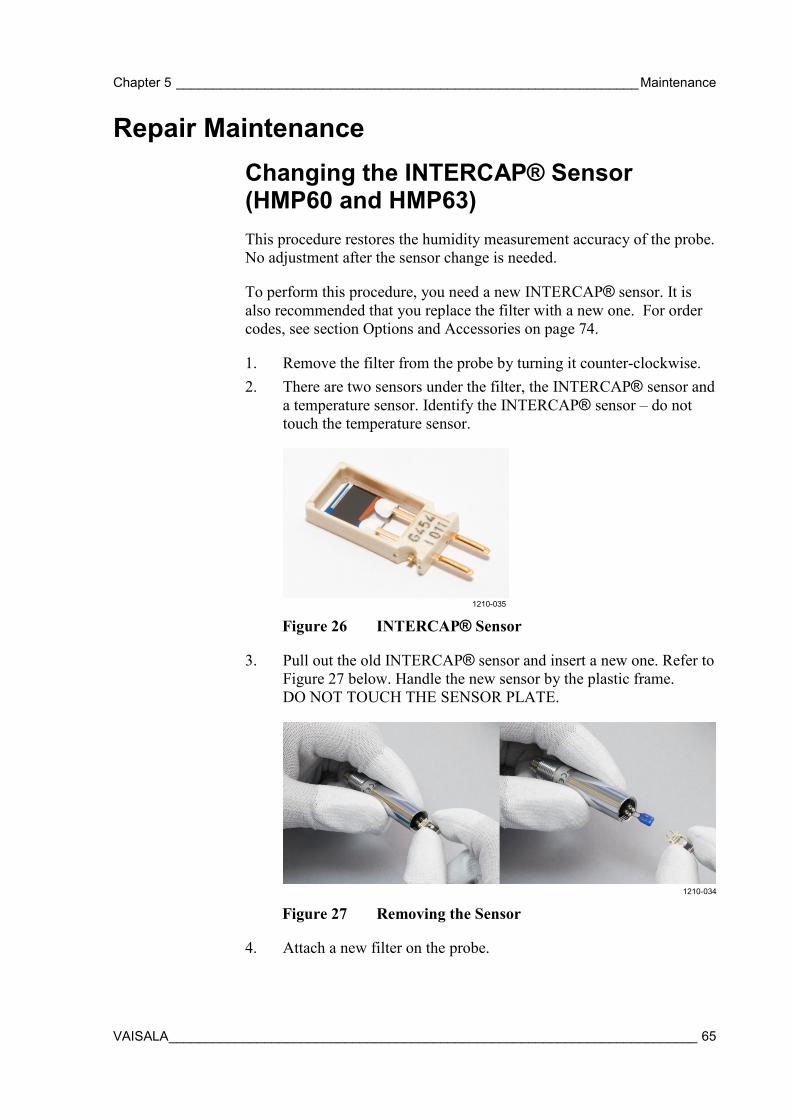
Chapter 5 _______________________________________________________________ Maintenance
VAISALA ________________________________________________________________________ 65
Repair Maintenance Changing the INTERCAP® Sensor (HMP60 and HMP63) This procedure restores the humidity measurement accuracy of the probe. No adjustment after the sensor change is needed.
To perform this procedure, you need a new INTERCAP® sensor. It is also recommended that you replace the filter with a new one. For order codes, see section Options and Accessories on page 74.
1. Remove the filter from the probe by turning it counter-clockwise. 2. There are two sensors under the filter, the INTERCAP® sensor and
a temperature sensor. Identify the INTERCAP® sensor – do not touch the temperature sensor.
1210-035
Figure 26 INTERCAP® Sensor
3. Pull out the old INTERCAP® sensor and insert a new one. Refer to Figure 27 below. Handle the new sensor by the plastic frame. DO NOT TOUCH THE SENSOR PLATE.
1210-034
Figure 27 Removing the Sensor
4. Attach a new filter on the probe.
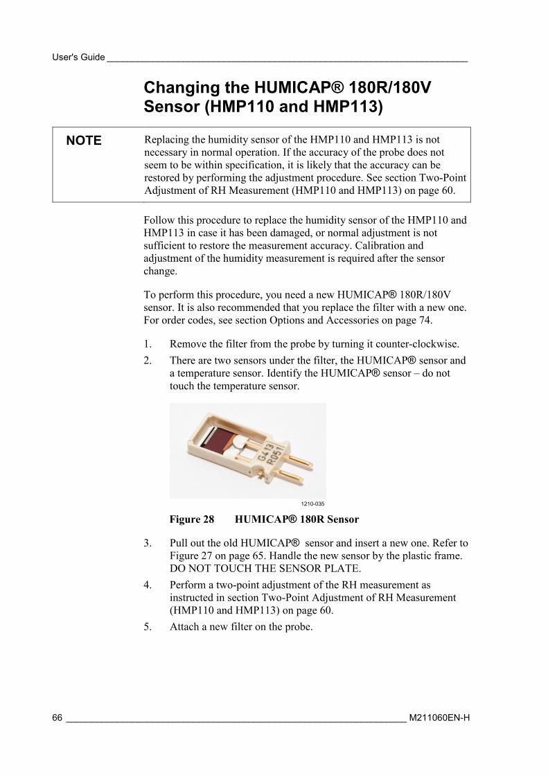
User's Guide _______________________________________________________________________
66 ___________________________________________________________________ M211060EN-H
Changing the HUMICAP® 180R/180V Sensor (HMP110 and HMP113)
NOTE Replacing the humidity sensor of the HMP110 and HMP113 is not necessary in normal operation. If the accuracy of the probe does not seem to be within specification, it is likely that the accuracy can be restored by performing the adjustment procedure. See section Two-Point Adjustment of RH Measurement (HMP110 and HMP113) on page 60.
Follow this procedure to replace the humidity sensor of the HMP110 and HMP113 in case it has been damaged, or normal adjustment is not sufficient to restore the measurement accuracy. Calibration and adjustment of the humidity measurement is required after the sensor change.
To perform this procedure, you need a new HUMICAP® 180R/180V sensor. It is also recommended that you replace the filter with a new one. For order codes, see section Options and Accessories on page 74.
1. Remove the filter from the probe by turning it counter-clockwise. 2. There are two sensors under the filter, the HUMICAP® sensor and
a temperature sensor. Identify the HUMICAP® sensor – do not touch the temperature sensor.
1210-035
Figure 28 HUMICAP® 180R Sensor
3. Pull out the old HUMICAP® sensor and insert a new one. Refer to Figure 27 on page 65. Handle the new sensor by the plastic frame. DO NOT TOUCH THE SENSOR PLATE.
4. Perform a two-point adjustment of the RH measurement as instructed in section Two-Point Adjustment of RH Measurement (HMP110 and HMP113) on page 60.
5. Attach a new filter on the probe.
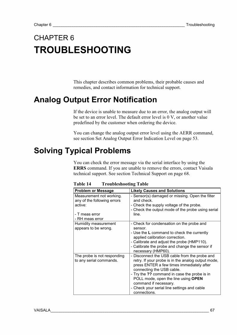
Chapter 6 ____________________________________________________________ Troubleshooting
VAISALA ________________________________________________________________________ 67
CHAPTER 6
TROUBLESHOOTING
This chapter describes common problems, their probable causes and remedies, and contact information for technical support.
Analog Output Error Notification If the device is unable to measure due to an error, the analog output will be set to an error level. The default error level is 0 V, or another value predefined by the customer when ordering the device.
You can change the analog output error level using the AERR command, see section Set Analog Output Error Indication Level on page 53.
Solving Typical Problems You can check the error message via the serial interface by using the ERRS command. If you are unable to remove the errors, contact Vaisala technical support. See section Technical Support on page 68.
Table 14 Troubleshooting Table Problem or Message Likely Causes and Solutions Measurement not working. any of the following errors active: - T meas error - RH meas error
- Sensor(s) damaged or missing. Open the filter and check.
- Check the supply voltage of the probe. - Check the output mode of the probe using serial
line.
Humidity measurement appears to be wrong.
- Check for condensation on the probe and sensor.
- Use the L command to check the currently applied calibration correction.
- Calibrate and adjust the probe (HMP110). - Calibrate the probe and change the sensor if
necessary (HMP60). The probe is not responding to any serial commands.
- Disconnect the USB cable from the probe and retry. If your probe is in the analog output mode, press ENTER a few times immediately after connecting the USB cable.
- Try the ?? command in case the probe is in POLL mode, open the line using OPEN command if necessary.
- Check your serial line settings and cable connections.
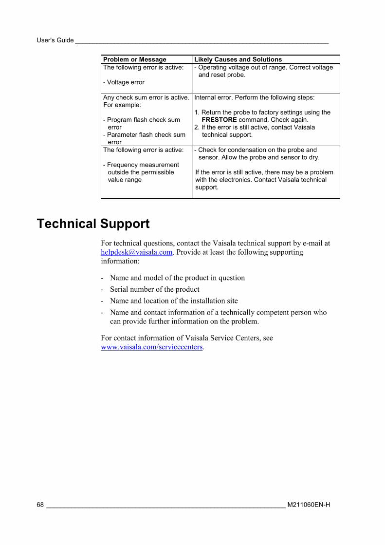
User's Guide _______________________________________________________________________
68 ___________________________________________________________________ M211060EN-H
Problem or Message Likely Causes and Solutions The following error is active: - Voltage error
- Operating voltage out of range. Correct voltage and reset probe.
Any check sum error is active. For example: - Program flash check sum
error - Parameter flash check sum
error
Internal error. Perform the following steps: 1. Return the probe to factory settings using the
FRESTORE command. Check again. 2. If the error is still active, contact Vaisala
technical support.
The following error is active: - Frequency measurement
outside the permissible value range
- Check for condensation on the probe and sensor. Allow the probe and sensor to dry.
If the error is still active, there may be a problem with the electronics. Contact Vaisala technical support.
Technical Support For technical questions, contact the Vaisala technical support by e-mail at [email protected]. Provide at least the following supporting information:
- Name and model of the product in question - Serial number of the product - Name and location of the installation site - Name and contact information of a technically competent person who
can provide further information on the problem.
For contact information of Vaisala Service Centers, see www.vaisala.com/servicecenters.
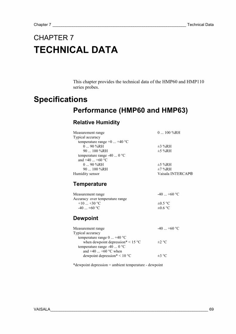
Chapter 7 _____________________________________________________________ Technical Data
VAISALA ________________________________________________________________________ 69
CHAPTER 7
TECHNICAL DATA
This chapter provides the technical data of the HMP60 and HMP110 series probes.
Specifications Performance (HMP60 and HMP63) Relative Humidity Measurement range 0 ... 100 %RH Typical accuracy temperature range +0 ... +40 °C 0 ... 90 %RH ±3 %RH 90 ... 100 %RH ±5 %RH temperature range -40 ... 0 °C and +40 ... +60 °C 0 ... 90 %RH ±5 %RH 90 ... 100 %RH ±7 %RH Humidity sensor Vaisala INTERCAP®
Temperature Measurement range -40 ... +60 °C Accuracy over temperature range +10 ... +30 °C ±0.5 °C -40 ... +60 °C ±0.6 °C
Dewpoint Measurement range -40 ... +60 °C Typical accuracy temperature range 0 ... +40 °C when dewpoint depression* < 15 °C ±2 °C temperature range -40 ... 0 °C and +40 ... +60 °C when dewpoint depression* < 10 °C ±3 °C *dewpoint depression = ambient temperature - dewpoint
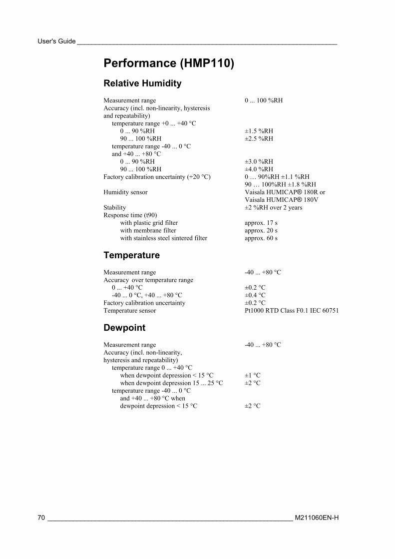
User's Guide _______________________________________________________________________
70 ___________________________________________________________________ M211060EN-H
Performance (HMP110) Relative Humidity Measurement range 0 ... 100 %RH Accuracy (incl. non-linearity, hysteresis and repeatability) temperature range +0 ... +40 °C 0 ... 90 %RH ±1.5 %RH 90 ... 100 %RH ±2.5 %RH temperature range -40 ... 0 °C and +40 ... +80 °C 0 ... 90 %RH ±3.0 %RH 90 ... 100 %RH ±4.0 %RH Factory calibration uncertainty (+20 °C) 0 … 90%RH ±1.1 %RH
90 … 100%RH ±1.8 %RH Humidity sensor Vaisala HUMICAP® 180R or
Vaisala HUMICAP® 180V Stability ±2 %RH over 2 years Response time (t90) with plastic grid filter approx. 17 s with membrane filter approx. 20 s with stainless steel sintered filter approx. 60 s
Temperature Measurement range -40 ... +80 °C Accuracy over temperature range 0 ... +40 °C ±0.2 °C -40 ... 0 °C, +40 ... +80 °C ±0.4 °C Factory calibration uncertainty ±0.2 °C Temperature sensor Pt1000 RTD Class F0.1 IEC 60751
Dewpoint Measurement range -40 ... +80 °C Accuracy (incl. non-linearity, hysteresis and repeatability) temperature range 0 ... +40 °C when dewpoint depression < 15 °C ±1 °C when dewpoint depression 15 ... 25 °C ±2 °C temperature range -40 ... 0 °C and +40 ... +80 °C when dewpoint depression < 15 °C ±2 °C
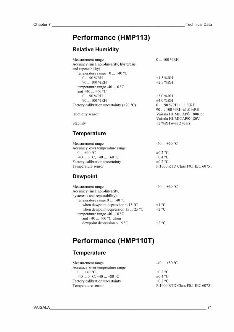
Chapter 7 _____________________________________________________________ Technical Data
VAISALA ________________________________________________________________________ 71
Performance (HMP113) Relative Humidity Measurement range 0 ... 100 %RH Accuracy (incl. non-linearity, hysteresis and repeatability) temperature range +0 ... +40 °C 0 ... 90 %RH ±1.5 %RH 90 ... 100 %RH ±2.5 %RH temperature range -40 ... 0 °C and +40 ... +60 °C 0 ... 90 %RH ±3.0 %RH 90 ... 100 %RH ±4.0 %RH Factory calibration uncertainty (+20 °C) 0 … 90 %RH ±1.1 %RH
90 … 100 %RH ±1.8 %RH Humidity sensor Vaisala HUMICAP® 180R or
Vaisala HUMICAP® 180V Stability ±2 %RH over 2 years
Temperature Measurement range -40 ... +60 °C Accuracy over temperature range 0 ... +40 °C ±0.2 °C -40 ... 0 °C, +40 ... +60 °C ±0.4 °C Factory calibration uncertainty ±0.2 °C Temperature sensor Pt1000 RTD Class F0.1 IEC 60751
Dewpoint Measurement range -40 ... +60 °C Accuracy (incl. non-linearity, hysteresis and repeatability) temperature range 0 ... +40 °C when dewpoint depression < 15 °C ±1 °C when dewpoint depression 15 ... 25 °C ±2 °C temperature range -40 ... 0 °C and +40 ... +60 °C when dewpoint depression < 15 °C ±2 °C
Performance (HMP110T) Temperature Measurement range -40 ... +80 °C Accuracy over temperature range 0 ... +40 °C ±0.2 °C -40 ... 0 °C, +40 ... +80 °C ±0.4 °C Factory calibration uncertainty ±0.2 °C Temperature sensor Pt1000 RTD Class F0.1 IEC 60751
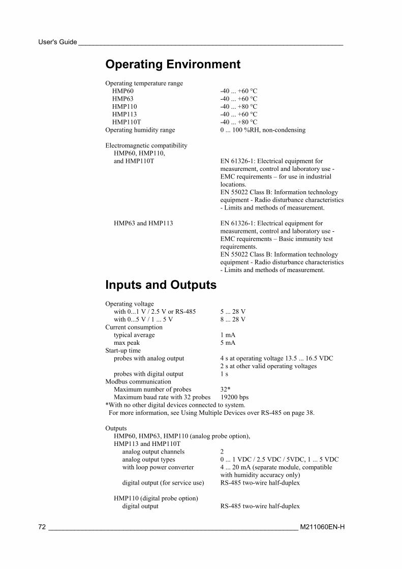
User's Guide _______________________________________________________________________
72 ___________________________________________________________________ M211060EN-H
Operating Environment Operating temperature range HMP60 -40 ... +60 °C HMP63 -40 ... +60 °C HMP110 -40 ... +80 °C HMP113 -40 ... +60 °C HMP110T -40 ... +80 °C Operating humidity range 0 ... 100 %RH, non-condensing Electromagnetic compatibility HMP60, HMP110, and HMP110T EN 61326-1: Electrical equipment for
measurement, control and laboratory use - EMC requirements – for use in industrial locations.
EN 55022 Class B: Information technology equipment - Radio disturbance characteristics - Limits and methods of measurement.
HMP63 and HMP113 EN 61326-1: Electrical equipment for
measurement, control and laboratory use - EMC requirements – Basic immunity test requirements.
EN 55022 Class B: Information technology equipment - Radio disturbance characteristics - Limits and methods of measurement.
Inputs and Outputs Operating voltage with 0...1 V / 2.5 V or RS-485 5 ... 28 V with 0...5 V / 1 ... 5 V 8 ... 28 V Current consumption typical average 1 mA max peak 5 mA Start-up time probes with analog output 4 s at operating voltage 13.5 ... 16.5 VDC 2 s at other valid operating voltages probes with digital output 1 s Modbus communication Maximum number of probes 32* Maximum baud rate with 32 probes 19200 bps *With no other digital devices connected to system. For more information, see Using Multiple Devices over RS-485 on page 38.
Outputs HMP60, HMP63, HMP110 (analog probe option), HMP113 and HMP110T analog output channels 2 analog output types 0 ... 1 VDC / 2.5 VDC / 5VDC, 1 ... 5 VDC with loop power converter 4 ... 20 mA (separate module, compatible
with humidity accuracy only) digital output (for service use) RS-485 two-wire half-duplex HMP110 (digital probe option) digital output RS-485 two-wire half-duplex
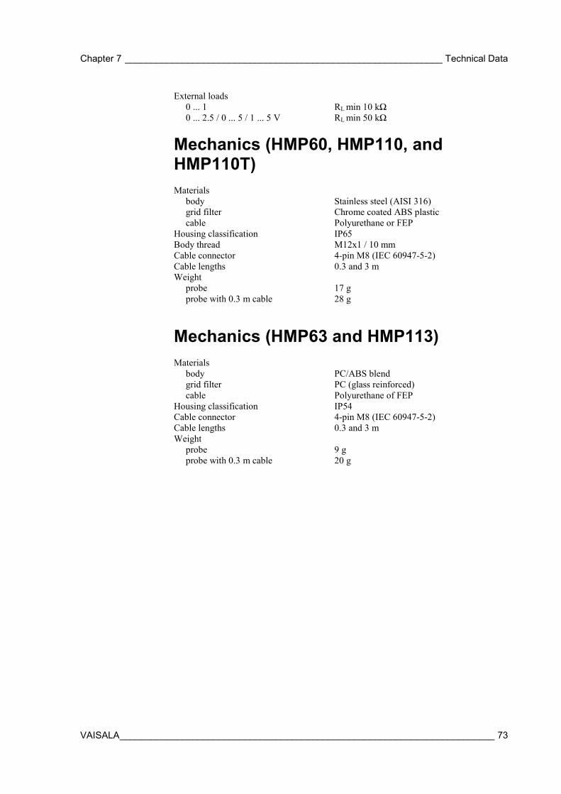
Chapter 7 _____________________________________________________________ Technical Data
VAISALA ________________________________________________________________________ 73
External loads 0 ... 1 RL min 10 kΩ 0 ... 2.5 / 0 ... 5 / 1 ... 5 V RL min 50 kΩ
Mechanics (HMP60, HMP110, and HMP110T) Materials body Stainless steel (AISI 316) grid filter Chrome coated ABS plastic cable Polyurethane or FEP Housing classification IP65 Body thread M12x1 / 10 mm Cable connector 4-pin M8 (IEC 60947-5-2) Cable lengths 0.3 and 3 m Weight probe 17 g probe with 0.3 m cable 28 g
Mechanics (HMP63 and HMP113) Materials body PC/ABS blend grid filter PC (glass reinforced) cable Polyurethane of FEP Housing classification IP54 Cable connector 4-pin M8 (IEC 60947-5-2) Cable lengths 0.3 and 3 m Weight probe 9 g probe with 0.3 m cable 20 g
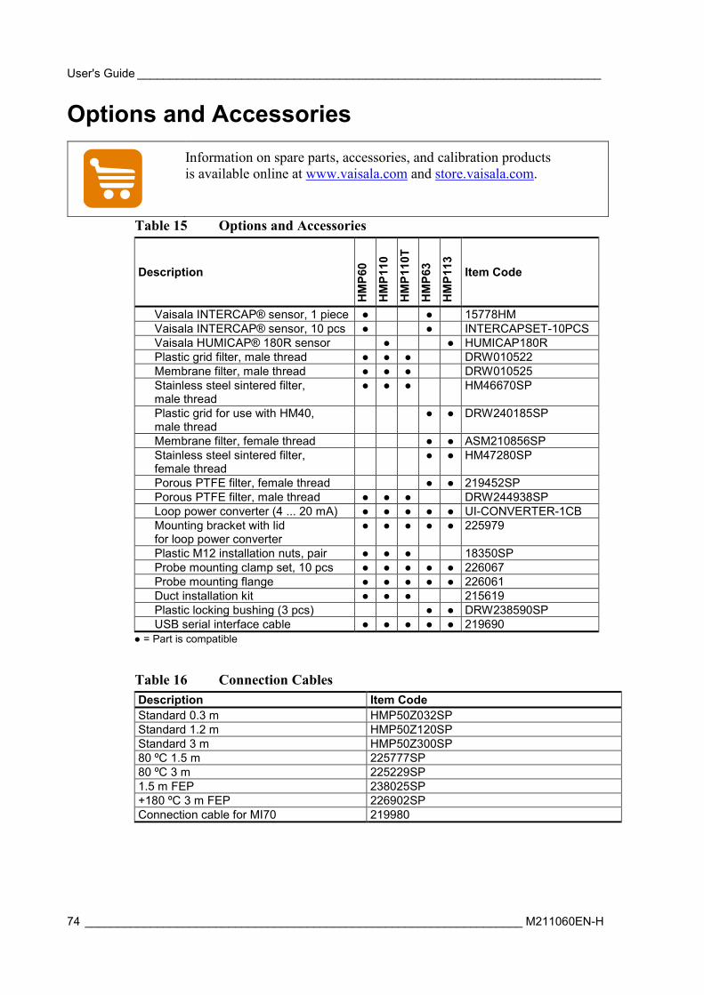
User's Guide _______________________________________________________________________
74 ___________________________________________________________________ M211060EN-H
Options and Accessories
Information on spare parts, accessories, and calibration products is available online at www.vaisala.com and store.vaisala.com.
Table 15 Options and Accessories
Description
HM
P60
HM
P110
HM
P110
T
HM
P63
HM
P113
Item Code
Vaisala INTERCAP® sensor, 1 piece 15778HM Vaisala INTERCAP® sensor, 10 pcs INTERCAPSET-10PCS Vaisala HUMICAP® 180R sensor HUMICAP180R Plastic grid filter, male thread DRW010522 Membrane filter, male thread DRW010525 Stainless steel sintered filter, male thread
HM46670SP
Plastic grid for use with HM40, male thread
DRW240185SP
Membrane filter, female thread ASM210856SP Stainless steel sintered filter, female thread
HM47280SP
Porous PTFE filter, female thread 219452SP Porous PTFE filter, male thread DRW244938SP Loop power converter (4 ... 20 mA) UI-CONVERTER-1CB Mounting bracket with lid for loop power converter
225979
Plastic M12 installation nuts, pair 18350SP Probe mounting clamp set, 10 pcs 226067 Probe mounting flange 226061 Duct installation kit 215619 Plastic locking bushing (3 pcs) DRW238590SP USB serial interface cable 219690
= Part is compatible
Table 16 Connection Cables Description Item Code Standard 0.3 m HMP50Z032SP Standard 1.2 m HMP50Z120SP Standard 3 m HMP50Z300SP 80 ºC 1.5 m 225777SP 80 ºC 3 m 225229SP 1.5 m FEP 238025SP +180 ºC 3 m FEP 226902SP Connection cable for MI70 219980
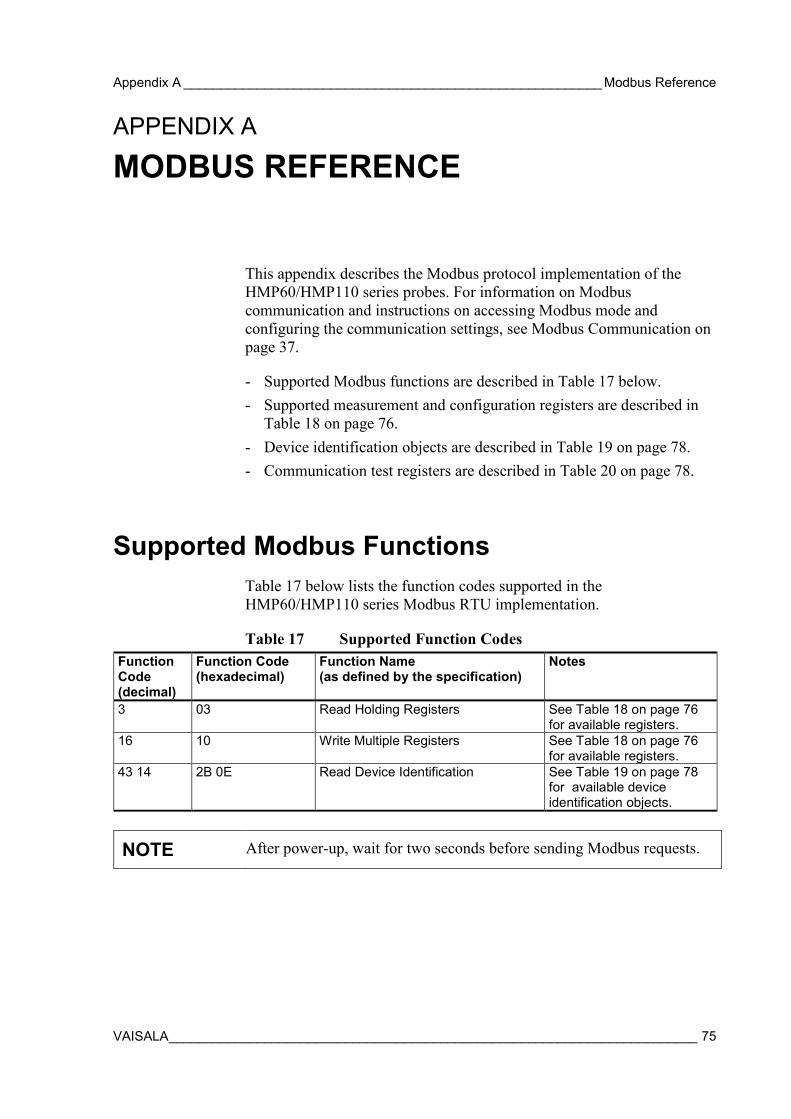
Appendix A _________________________________________________________ Modbus Reference
VAISALA ________________________________________________________________________ 75
APPENDIX A
MODBUS REFERENCE
This appendix describes the Modbus protocol implementation of the HMP60/HMP110 series probes. For information on Modbus communication and instructions on accessing Modbus mode and configuring the communication settings, see Modbus Communication on page 37.
- Supported Modbus functions are described in Table 17 below. - Supported measurement and configuration registers are described in
Table 18 on page 76. - Device identification objects are described in Table 19 on page 78. - Communication test registers are described in Table 20 on page 78.
Supported Modbus Functions Table 17 below lists the function codes supported in the HMP60/HMP110 series Modbus RTU implementation.
Table 17 Supported Function Codes Function Code (decimal)
Function Code (hexadecimal)
Function Name (as defined by the specification)
Notes
3 03 Read Holding Registers See Table 18 on page 76 for available registers.
16 10 Write Multiple Registers See Table 18 on page 76 for available registers.
43 14 2B 0E Read Device Identification See Table 19 on page 78 for available device identification objects.
NOTE After power-up, wait for two seconds before sending Modbus requests.
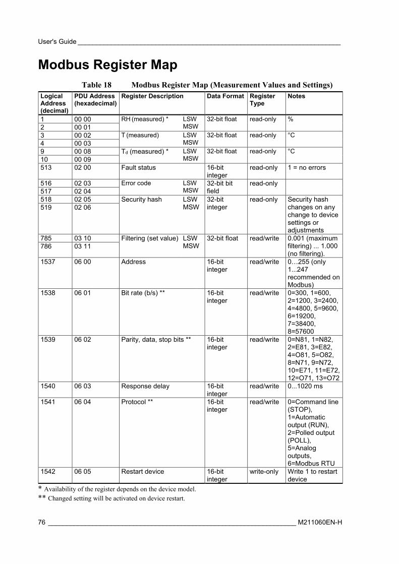
User's Guide _______________________________________________________________________
76 ___________________________________________________________________ M211060EN-H
Modbus Register Map Table 18 Modbus Register Map (Measurement Values and Settings)
Logical Address (decimal)
PDU Address (hexadecimal)
Register Description Data Format Register Type
Notes
1 00 00 RH (measured) * LSW MSW
32-bit float read-only % 2 00 01 3 00 02 T (measured) LSW
MSW 32-bit float read-only °C
4 00 03 9 00 08 Td (measured) * LSW
MSW 32-bit float read-only °C
10 00 09 513 02 00 Fault status 16-bit
integer read-only 1 = no errors
516 02 03 Error code LSW MSW
32-bit bit field
read-only 517 02 04 518 02 05 Security hash LSW
MSW 32-bit integer
read-only Security hash changes on any change to device settings or adjustments
519 02 06
785 03 10 Filtering (set value) LSW MSW
32-bit float read/write 0.001 (maximum filtering) ... 1.000 (no filtering).
786 03 11
1537 06 00 Address 16-bit integer
read/write 0…255 (only 1...247 recommended on Modbus)
1538 06 01 Bit rate (b/s) ** 16-bit integer
read/write 0=300, 1=600, 2=1200, 3=2400, 4=4800, 5=9600, 6=19200, 7=38400, 8=57600
1539 06 02 Parity, data, stop bits ** 16-bit integer
read/write 0=N81, 1=N82, 2=E81, 3=E82, 4=O81, 5=O82, 8=N71, 9=N72, 10=E71, 11=E72, 12=O71, 13=O72
1540 06 03 Response delay 16-bit integer
read/write 0...1020 ms
1541 06 04 Protocol ** 16-bit integer
read/write 0=Command line (STOP), 1=Automatic output (RUN), 2=Polled output (POLL), 5=Analog outputs, 6=Modbus RTU
1542 06 05 Restart device 16-bit integer
write-only Write 1 to restart device
* Availability of the register depends on the device model. ** Changed setting will be activated on device restart.
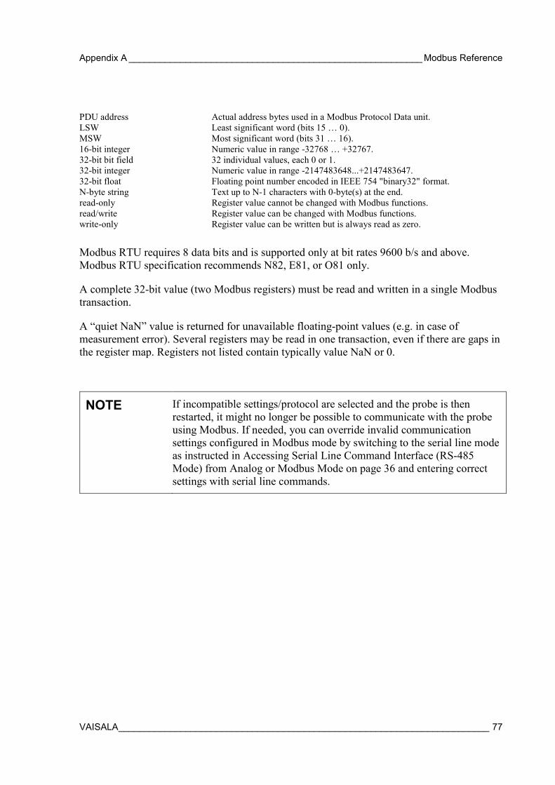
Appendix A _________________________________________________________ Modbus Reference
VAISALA ________________________________________________________________________ 77
PDU address Actual address bytes used in a Modbus Protocol Data unit. LSW Least significant word (bits 15 … 0). MSW Most significant word (bits 31 … 16). 16-bit integer Numeric value in range -32768 … +32767. 32-bit bit field 32 individual values, each 0 or 1. 32-bit integer Numeric value in range -2147483648...+2147483647. 32-bit float Floating point number encoded in IEEE 754 "binary32" format. N-byte string Text up to N-1 characters with 0-byte(s) at the end. read-only Register value cannot be changed with Modbus functions. read/write Register value can be changed with Modbus functions. write-only Register value can be written but is always read as zero.
Modbus RTU requires 8 data bits and is supported only at bit rates 9600 b/s and above. Modbus RTU specification recommends N82, E81, or O81 only.
A complete 32-bit value (two Modbus registers) must be read and written in a single Modbus transaction.
A “quiet NaN” value is returned for unavailable floating-point values (e.g. in case of measurement error). Several registers may be read in one transaction, even if there are gaps in the register map. Registers not listed contain typically value NaN or 0.
NOTE If incompatible settings/protocol are selected and the probe is then restarted, it might no longer be possible to communicate with the probe using Modbus. If needed, you can override invalid communication settings configured in Modbus mode by switching to the serial line mode as instructed in Accessing Serial Line Command Interface (RS-485 Mode) from Analog or Modbus Mode on page 36 and entering correct settings with serial line commands.
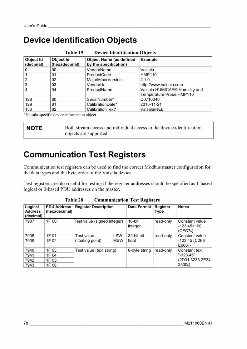
User's Guide _______________________________________________________________________
78 ___________________________________________________________________ M211060EN-H
Device Identification Objects Table 19 Device Identification Objects
Object Id (decimal)
Object Id (hexadecimal)
Object Name (as defined by the specification)
Example
0 00 VendorName Vaisala 1 01 ProductCode HMP110 2 02 MajorMinorVersion 2.1.0 3 03 VendorUrl http://www.vaisala.com 4 04 ProductName Vaisala HUMICAP® Humidity and
Temperature Probe HMP110 128 80 SerialNumber* D0710040 129 81 CalibrationDate* 2015-11-21 130 82 CalibrationText* Vaisala/HEL
* Vaisala-specific device information object
NOTE Both stream access and individual access to the device identification objects are supported.
Communication Test Registers Communication test registers can be used to find the correct Modbus master configuration for the data types and the byte order of the Vaisala device.
Test registers are also useful for testing if the register addresses should be specified as 1-based logical or 0-based PDU addresses on the master.
Table 20 Communication Test Registers Logical Address (decimal)
PDU Address (hexadecimal)
Register Description Data Format Register Type
Notes
7937 1F 00 Test value (signed integer) 16-bit integer
read-only Constant value -123.45×100 (CFC7h)
7938 1F 01 Test value (floating point)
LSW MSW
32-bit bit float
read-only Constant value -123.45 (C2F6 E666h)
7939 1F 02
7940 1F 03 Test value (text string) 8-byte string read-only
Constant text "-123.45" (2D31 3233 2E34 3500h)
7941 1F 04 7942 1F 05 7943 1F 06

www.vaisala.com
*M211060EN*