Embed Size (px)
Citation preview

2181063 A - December 2013
Installation and operating
instructions
VADODigital Electric
Installers please note these InstructIons are to be left wIth the user
CONTENTS Page
Important safety information .......................................................... 1
Introduction ................................................................................... 2
Specification ................................................................................... 2
Advice to users ............................................................................... 2
Main components .......................................................................... 3
Electrical requirements ................................................................. 4 − 5
Water requirements ........................................................................ 6
Siting of the shower ..................................................................... 7 − 8
Fitting the remote pack .............................................................. 9 − 10
Plumbing connections ............................................................... 11 − 13
Fitting the bulkhead................................................................... 14 − 15
Electrical connections .................................................................... 16
Fitting the control panel bracket .................................................... 17
Fitting the control panel ................................................................ 18
Fitting the remote pack cover ........................................................ 18
Commissioning .......................................................................... 19 − 20
Operating the shower ............................................................... 21 − 22
Operating functions ................................................................... 23 − 24
Cleaning ....................................................................................... 24
Cleaning the filter .......................................................................... 25
Spare parts ................................................................................ 26 − 27
Fault finding .............................................................................. 28 − 29
Guarantee, service policy, etc. ...................................................rear cover
VADO Digital Electric
To check the product suitability for commercial and multiple installations, please contact Vado`s specification advisory service before installation.
Telephone: 0844 980 0748
WARNINGThis appliance can be used by children aged from 8 years and above and persons with reduced physical, sensory or mental capabilities or lack of experience or knowledge if
they have been given supervision or instruction concerning use of the appliance in a safe way and understand the hazards involved. Children may not play with the appliance.
Cleaning and user maintenance shall not be made by children without supervision.

1
Products manufactured by Vado are safe and without risk provided they are installed, used and maintained in good working order in accordance with our instructions and recommendations.WARNING: DO NOT operate shower if frozen, or suspected of being frozen. It must thaw out before using.DO NOT operate the unit if the showerhead or spray hose becomes damaged.DO NOT restrict flow out of shower by placing showerhead in direct contact with your body.DO NOT operate the shower if water ceases to flow during use or if water has entered inside the unit because of an incorrectly fitted cover.
PLEASE READ THIS IMPORTANT SAFETY INFORMATION
1 GENERAL1.1 Isolate the electrical and water supplies before
removing the cover.1.2 Read all of these instructions and retain them
for later use.1.3 DO NOT take risks with plumbing or electrical
equipment.1.4 Isolate electrical and water supplies before
proceeding with the installation.1.5 The unit must be mounted onto the finished
wall surface (on top of the tiles). DO NOT tile up to or seal around ANY PART of the unit using silicone sealer after fixing to the wall. Special care must be taken NOT TO BLOCK OR SEAL ANY PRD VENTS ON THE UNIT.
1.6 Contact Customer Service (see back page), if any of the following occur:
a) If it is intended to operate the shower at pressures above the maximum or below the minimum stated.
b) If the unit shows a distinct change in performance.c) If the shower is frozen.1.7 If it is intended to operate the shower in areas
of hard water (above 200 ppm temporary hardness), a scale inhibitor may have to be fitted. For advice on the Scale Inhibitor, contact Customer Service.
1.8 The showerhead must be cleaned regularly with descalent to remove scale and debris, otherwise restrictions to the flow on the outlet of the unit will result in higher temperatures and could also cause the (PRD) Pressure Relief Device in the unit to operate.
1.9 This product is not suitable for mounting into steam rooms or steam cubicles.
2 PLUMBING2.1 The plumbing installation must comply with
Water Regulations, Building Regulations or any particular regulations as specified by Local Water Company or Water Undertakers and should be in accordance with BS EN 806.
2.2 The supply pipe must be flushed to clear debris before connecting to the shower unit.
2.3 DO NOT solder pipes or fittings within 300mm of the shower unit, as heat can transfer along the pipework and damage components.
2.4 DO NOT fit any form of outlet flow control as the outlet acts as a vent for the heater can.
2.5 DO NOT use excessive force when making connections to the flexible hose or showerhead, finger tight is sufficient.
2.6 All plumbing connections must be completed before making the electrical connections.
2.7 This appliance MUST not be connected to the inlet supply by a hose-set.
3 ELECTRICAL3.1 The installation must comply with BS 7671
‘Requirements for electrical installations’ (IEE wiring regulations), building regulations or any particular regulations as specified by the local Electrical Supply Company.
3.2 This appliance MUST be earthed.3.3 In accordance with ‘The Plugs and Sockets etc.
(Safety) Regulations 1994’, this appliance is intended to be permanently connected to the fixed wiring of the electrical mains system.
3.4 Make sure all electrical connections are tight to prevent overheating.
3.5 A 30mA residual current device (RCD) MUST be installed in all UK electric and pumped shower circuits. This may be part of the consumer unit or a separate unit.
3.6 Switch off immediately at isolating switch if water ceases to flow during use.
3.7 Other electrical equipment i.e. extractor fans, pumps must not be connected to the circuits within the unit.
3.8 Switch off at isolating switch when not in use. This is a safety procedure recommended with all electrical appliances.
3.9 As with all electrical appliances it is recommended to have the shower and installation checked at least every two years by a competent electrician to ensure there is no deterioration due to age and usage.

2
VADO Digital Electric
ADVICE TO USERS
The following points will help you understand how the shower operates:
a. The electric heating elements operate at a constant rate at your chosen power setting. It is the rate of the water passing through the heater unit which determines the shower temperature at a given setting. (The slower the flow the hotter the water becomes, and the faster the flow the cooler the water).
b. During the winter the cold water supply will be cooler than in the summer months. Therefore, the temperature of the water will vary from season to season on any one setting of the control buttons, e.g. if you have chosen 'Economy' power for your preferred shower temperature in the summer, you will have to select the 'High' setting and adjust the temperature control during the winter months.
c. The stabiliser valve minimises variations in shower temperature during mains water pressure changes. If changes in shower temperature are experienced during normal use, it will most likely be caused by the water pressure falling near to or below the minimum level. The drop in pressure may be due to water being drawn off at other points in the house while the shower is in use. If pressure drops appreciably below the minimum, the heating elements will automatically cut out.
If ever the water becomes too hot and you cannot obtain cooler water, first check the showerhead has not become blocked.
INTRODUCTIONThis book contains all the necessary fitting and operating instructions for your remote electric shower – please read them carefully.
The shower installation must be carried out by a suitably qualified person and in the sequence of this instruction book.
Care taken during the installation will give a long, trouble-free life from your shower.
SPECIFICATIONSElectrical Nominal power Nominal power rating at 240V rating at 230V 8.5kW – (40A MCB rating) 7.8kW – (40A MCB rating) 9.5kW – (40A MCB rating) 8.7kW – (40A MCB rating)
Water Inlet connection – 15 mm diameter. Outlet connection – ½” BSP male thread.
Entry Points Water – Right: back, bottom.
Cable – Right: back, top.Materials External parts - Electroplated Backplate, cover, controls, showerhead – ABS. Sprayplate – Acetal. Elements – Minerally insulated corrosion resistant metal sheathing.Dimensions (in mm) control panel remote pack Height 235 338 Width 180 208 Depth 40 98
Standards and Approvals Splashproof rating IPX4.
Complies with the requirements of current British and European safety standards for household and similar electrical appliances.
Complies with the requirements for the BEAB mark.
Meets with Compliance with European Community Directives (CE).Replacement parts can be ordered from Vado Customer Service. See ‘spare parts’ for details.
Due to continuous improvement and updating, specification may be altered without prior notice.
IMPORTANT: When first installed (or following replacement of the PRD), the unit will be empty. It is essential the heater assembly contains water before the elements are switched on. As this unit has electronic control, it is vital that the commissioning procedure is followed. Failure to carry out this operation will result in damage to the unit and will invalidate the guarantee.
ELECTROMAGNETIC COMPATIBILITY This product is intended for domestic use.
This product may temporarily be affected by electromagnetic disturbance near to the installation that could cause temporary operation of the low pressure indicator together with switching to the cold power selection. If problems persist, contact Vado Customer Service (see rear page).

3
VADO Digital Electric
MAIN COMPONENTSRemote pack (Fig.1)
1 Top cable entry
2 Bottom pipe entry
3 Rear pipe entry area
4 Rear cable entry area
5 Wall screw fixing
6 Terminal block
7 Printed circuit board
8 Stabilising valve
9 Solenoid valve
10 Guide pockets
11 Can and element assembly
12 Thermal safety cut-out (main)
13 Earth connection
14 Control cable clamp
15 Thermal cut-out (outlet)
16 Outlet pipe
17 Transformer
18 Connector socket
19 Stepper motor
20 Trimplate
Control panel (Fig.2)
21 Control cable exit
22 Access plate
Pack contents
Control panel
Remote pack
Heated water tube (white)
PRD tube (clear)
Connecting cable
Five position showerhead
Bulkhead fittings
Instructions, guarantee, template etc.
Riser rail kit boxed separately
338 mm
68 mm
145 mm
208 mm
47 mm
Fig.1
Fig.2
10
22
8
19
18
17
20
16
15
14
13
12
11
9
7 4
3
2
6
5
1
10
10
5
21

4
W-006-AWARNING!THIS APPLIANCE MUST BE EARTHED
Meter Incomingsupplyfuse
Metertails
Consumerunit
Pull cordisolating switch
Showerunit
Fuse orMCB
RCD(can be part ofconsumer unit)
80A or 100Amain switch
Table A
MCB
30/32A
32A
40A
40A
40A
40/45A
45A
cartridgefuse
30A
35A
35A
45A
45A
45A
45A
unit rating
7.0kW
7.5kW
8.0kW
8.5kW
9.0kW
9.5kW
10.5kW
CIRCUIT PROTECTION
Fig.4 Schematic of installation circuit
ELECTRICAL REQUIREMENTS
The installation, supply cable and circuit protection must conform with BS 7671 (IEE wiring regulations) and be suf�cient for the amperage required.The following notes are for guidance only:1 The shower must only be connected to a
230-240V ac supply. If you are installing a shower with a kilowatt rating above 9kW, it is advisable to contact the local electricity supply company.
1.1 The electrical rating of the shower is shown on the rating label (Fig.3) within the unit.
2 Before making any sort of electrical connection within the installation make sure that no terminal is live. If in any doubt, switch off the whole installation at the mains supply and remove the correct fuse.
3 The shower must be connected to its own independent electrical circuit. IT MUST NOT be connected to a ring main, spur, socket outlet, lighting circuit or cooker circuit.
3.1 The electrical supply must be adequate for the loading of the unit and existing circuits.
4 Check your consumer unit (main fuse box) has a main switch rating of 80A or above and that it has a spare fuse way which will take the fuse or Miniature Circuit Breaker (MCB) necessary for the shower (Fig.4).
4.1 If your consumer unit has a rating below 80A or if there is no spare fuse way, then the installation will not be straightforward and may require a new consumer unit serving the house or just the shower.
4.2 You will need to contact the local electricity company. They will check the supply and carry out what is necessary.
5 For close circuit protection DO NOT use a rewireable fuse. Instead use a suitably rated Miniature Circuit Breaker (MCB) or cartridge fuse (see Table A).
5.1 A 30mA residual current device (RCD) MUST be installed in all UK electric and pumped shower circuits. This may be part of the consumer unit or a separate unit.
Fig.3 VadoWedmore Road, CheddarSomerset, BS27 3EB
RATED PRESSUREMODEL No. 00000000SERIAL No. 00000000
MAX. PRESSURE
MIN. PRESSURE

5
Table B
Note: Cable selection is dependent on derating factors
Twin and earth PVC insulated cableCurrent carrying capacity
In conduittrunking
6mm²38A
10mm²52A
16mm²69A
Installed in an insulated wall
6mm²32A
10mm²43A
16mm²57A
Clipped director buried in a non-insulated
wall
6mm²46A
10mm²63A
16mm²85A
6mm2 10mm2 16mm2
*The method below may be used by installers to determine the approximate
size of the incoming cable.
1. Measure the width of an individual strand, and half that measurment to find (r), e.g: 1.34mm ÷ 2 = (r) 0.67mm
2. Multiply (r) x (r) x 3.14, e.g: (r) 0.67 x (r) 0.67 x 3.14 = 1.41mm2
3. Multiply this by the number of wire strands (usually 7), e.g: 1.41mm2 x 7 = 9.87mm2.
4. The number obtained would suggest 10mm2 wiring.
*PLEASE NOTE: If unsure, consult a qualified Electrician.
6 A 45 amp double pole isolating switch with a minimum contact gap of 3 mm in both poles must be incorporated in the circuit.
6.1 It must have a mechanical indicator showing when the switch is in the OFF position, and the wiring must be connected to the switch without the use of a plug or socket outlet.
6.2 The switch must be accessible and clearly identifiable, but out of reach of a person using a fixed bath or shower, except for the cord of a cord operated switch, and should be placed so that it is not possible to touch the switch body while standing in a bath or shower cubicle. It should be readily accessible to switch off after using the shower.
7 Where shower cubicles are located in any rooms other than bathrooms, all socket outlets in those rooms must be protected by a 30mA RCD.
8 The current carrying capacity of the cable must be at least that of the shower circuit protection (see Table B).
8.1 To obtain full advantage of the power provided by the shower, use the shortest cable route possible from the consumer unit to the shower.
8.2 It is also necessary to satisfy the disconnection time and thermal constraints which means that for any given combination of current demand, voltage drop and cable size, there is a maximum permissible circuit length.
9 The shower circuit should be separated from other circuits by at least twice the diameter of the cable or conduit.
9.1 The current rating will be reduced if the cabling is bunched with others, surrounded by thermal loft or wall insulation or placed in areas where the ambient temperature is above 30°C. Under these conditions, derating factors apply and it is necessary to select a larger cable size.
9.2 In the majority of installations, the cable will unavoidably be placed in one or more of the above conditions. This being so, it is strongly recommended to use a minimum of 10mm cabling throughout the shower installation.
9.3 In any event, it is essential that individual site conditions are assessed by a competent electrician in order to determine the correct cable size and permissible circuit length.

6
WATER REQUIREMENTSThe installation must be in accordance with Water Regulations/Bylaws. To guarantee activation of the heating elements, the shower must be connected to a mains water supply with a minimum running pressure of 100kPa (1.0 bar) at a minimum flow rate of eight litres per minute for the 8.5kW rated model and nine litres per minute for the 9.5kW rated model.
For all units the maximum static pressure must be no greater than 1 000kPa (10 bar).
If in any doubt, the pressure should be checked.
Note: If the stated flow rate is not available, it may not be possible to achieve optimum performance from the unit throughout the year.
The water supply can be taken from a cold water storage cistern provided there is a minimum head of ten metres. Minimum head is the vertical distance from the base of the cistern to the showerhead. It must be an independent supply to the shower only.
If it is intended to operate the shower at pressures above the maximum or below the minimum stated, contact Customer Service for advice.
Fig.5 shows a typical system layout.
Isolating stopvalve
Remote Pack
Double pole
isolating switch
Separate permanently connected supply
from consumer unit
Mains water supply
Control Panel
Heated water pipe
Control cable
Mains electric supply (via double pole switch)
Fig.5 Diagrammatic view (not to scale)

7
SITING OF THE SHOWER
IMPORTANT: If installing onto a tiled wall always mount the unit on the surface of the tiles. NEVER tile up to the unit.
The heated water pipe and control cable are both 3.5 metres in length, so position the remote pack within this distance from the control panel and bulkhead.
Note: The control cable is supplied with protective dust covers fitted at either end. DO NOT remove them until all installation work is complete and ready for the final connection to the control panel and remote pack.
Refer to Fig.6 for correct siting of shower.
Position the control panel where it will NOT be in direct contact with water from the showerhead. Position the remote pack vertically and accessible for maintenance purposes.
Note: Water Regulations requires that the showerhead be ‘constrained by a fixed or sliding attachment so that it can only discharge water at a point not less than 25mm above the spill-over level of the relevant bath, shower tray or other fixed appliance’ (Fig.6). The use of the supplied soap dish will usually meet this requirement, but if the showerhead can be placed within a bath, basin or shower tray, then a double check valve, or a similar device, must be fitted in the supply pipework to prevent back-flow.
Pressure relief safety deviceA pressure relief device (PRD) is designed into the shower unit which complies with European standards. The PRD (Fig.7) provides a level of appliance protection should an excessive build up of pressure occur within the shower.
If the PRD operates, then water will eject from the clear PRD tube, so make sure the tube, when eventually installed, is routed carefully to waste.
WARNING!
The shower must not be positioned where it will be subjected to freezing
conditions.
Outline of bath or shower tray
Bulkhead can be mounted either
side of riser rail
25 mm minimum
Soap dish retaining
ring
Heated water pipe
Control cable
Mains cold water supply. Bottom entry
can be surface mounted.
All other entries must be from rear.
Spillover level
Height of showerheadto suit user'srequirement
Control panel
must not be within
1 metre from base
Fig.6 Diagrammatic view (not to scale)
WARNING!
Under no circumstance should the control cable be extended or shortened, or the heated water
pipe extended. This will impair the performance of the shower and
invalidate the guarantee.
Outlet pipe
Can
PRD
Fig.7

8
In the event of the PRD operating, turn off the electricity-and water supplies to the shower at the isolating switch and stopvalve. Contact Customer Service for advice on replacing the PRD.
DO NOT operate the shower with a damaged or kinked shower hose, or a blocked showerhead which can cause the PRD to operate.
When commissioning, the showerhead must be removed from the flexible hose. If not removed, it may cause the PRD to operate.
Routing control cable and heated waterpipeAfter deciding the position of the riser rail and control panel, you may wish first to channel a route for the semi-rigid heated water pipe and the control cable from the remote pack position to the control panel and bulkhead position.
The control cable must exit the shower cubicle wall through a 15 mm hole, marked ‘B’ on the supplied fixing template (Fig.8 shows an example). Place the template on the wall and mark the position of the 15 mm hole.
Drill and channel a route as required. Place and position the control cable between the remote pack and control panel. Make sure there is enough slack cable at the remote pack end for the control panel to be removed should the need arise for future maintenance
Within the shower cubicle, the end of the control cable outer sleeve must be flush with the finished wall surface to allow easy installation, and the inner cable should be loose and able to slide through the outer sleeve when finally installing the control panel.
It is advisable to seal the outer sleeve in the hole using a silicon seal.
Make good the wall, including any tiling, as all the units must be screwed to the finished wall surface.
IMPORTANT: In the shower area the control cable linking the remote pack and control panel must be secured by routing through conduit, trunking or capping if embedding in the wall. It must NOT be surface clipped.
A A
A
B
A
Fig.8
400mmapprox
250mmapprox
Fig.9
9
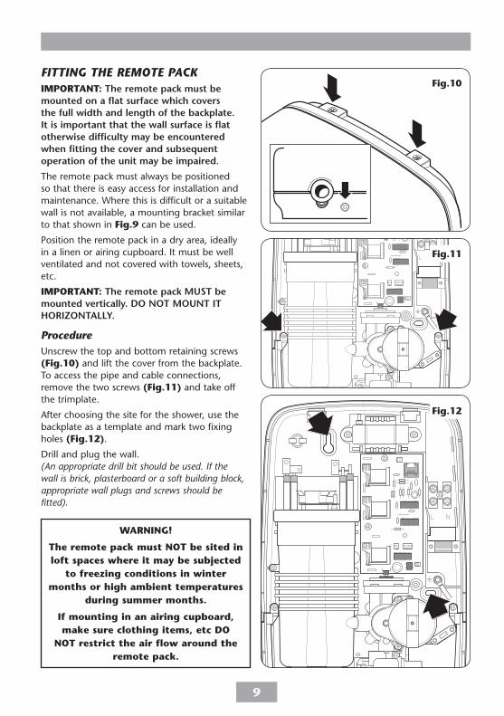
FITTING THE REMOTE PACKIMPORTANT: The remote pack must be mounted on a flat surface which covers the full width and length of the backplate. It is important that the wall surface is flat otherwise difficulty may be encountered when fitting the cover and subsequent operation of the unit may be impaired.
The remote pack must always be positioned so that there is easy access for installation and maintenance. Where this is difficult or a suitable wall is not available, a mounting bracket similar to that shown in Fig.9 can be used.
Position the remote pack in a dry area, ideally in a linen or airing cupboard. It must be well ventilated and not covered with towels, sheets, etc.
IMPORTANT: The remote pack MUST be mounted vertically. DO NOT MOUNT IT HORIZONTALLY.
ProcedureUnscrew the top and bottom retaining screws (Fig.10) and lift the cover from the backplate. To access the pipe and cable connections, remove the two screws (Fig.11) and take off the trimplate.
After choosing the site for the shower, use the backplate as a template and mark two fixing holes (Fig.12).
Drill and plug the wall.(An appropriate drill bit should be used. If the wall is brick, plasterboard or a soft building block, appropriate wall plugs and screws should be fitted).
WARNING!
The remote pack must NOT be sited in loft spaces where it may be subjected
to freezing conditions in winter months or high ambient temperatures
during summer months.
If mounting in an airing cupboard, make sure clothing items, etc DO
NOT restrict the air flow around the remote pack.
Fig.10
Fig.11
Fig.12

10
Screw top fixing screw into position leaving the base of the screw head protruding 6 mm out from the wall.
Entry positions for the mains water are from the bottom or from the rear.
Cable entry is via the top or rear.
Note: Deviations from the designated entry points will invalidate product approvals.
If a bottom surface entry is required for the mains cold water then the necessary hole will need to be cut out in the trimplate and cover (Fig.13).
If a surface cable entry from the top is required then the relevant hole in the backplate will need to be cut out (Fig.14).
Hook the backplate over the top screw and fit the bottom fixing screw into position.
Do not fully tighten the screws at this stage, as the fixing holes are elongated to allow for out of square adjustment after the plumbing connections have been completed.
remove
Bottom View
remove
wall
Top view
Fig.14
Fig.13

11
PLUMBING CONNECTIONSPlumbing to be carried out before wiring
DO NOT use jointing compounds on any pipe fittings for the installation.
DO NOT use solder fittings near the shower unit as heat can transfer along the pipework and damage components.
Compression fittings MUST be used to connect to the inlet of the remote pack (push-on fittings must not be used as the remote pack inlet may not fully enter this type of fitting to provide a watertight seal).
Note: An additional stopvalve, complying with Water Regulations, MUST be fitted in the mains water supply to the remote pack as an independent means of isolating the water supply should maintenance or servicing be necessary.
IMPORTANT: Before completing the connection of the water supply to the inlet of the remote pack, flush out the pipework to remove all swarf and system debris. To do this connect a hose to the pipework and turn on the mains water supply long enough to clear the debris to waste.
ProcedureTurn off the water supply either at the mains stopvalve or the isolating stopvalve. Connect the mains water supply to the inlet of the remote pack via a 15mm x 15mm elbow compression fitting (not supplied).
If installing a feed pipe from the rear or bottom, the centre of the inlet valve to the wall surface is 20mm (fig.15).
Note: If entry is from the rear, the nut of the compression fitting will be partially behind the surface of the wall (fig.15). This area must be left clear when plastering over the pipework in order to make the nut accessible for future adjustments.
WARNING!
The outlet of the shower acts as a vent and must not be connected to anything other than the hose and
showerhead supplied.20 mm
Fig.15
12
Make sure the backplate is square on the wall and tighten the two retaining screws which hold it to the wall.
Turn on the mains water supply and check for leaks in the pipework connection to the remote pack.
Note: At this stage no water can flow through the unit.
The remote pack is connected to the bulkhead outlet by means of a semi-rigid white 10 mm plastic water pipe which carries the heated water. This pipe can be channelled in a wall, plumbed through a wall or hidden behind a studded wall. The pipe can be run up to 3.5 metres away from the remote pack. Any surplus can be cut off as required.
Note: The water outlet does not need to be vertically above or below the control panel. If required the outlet adaptor and control panel can be placed on different walls as long as the control panel is not in the direct line of any spray when in use.
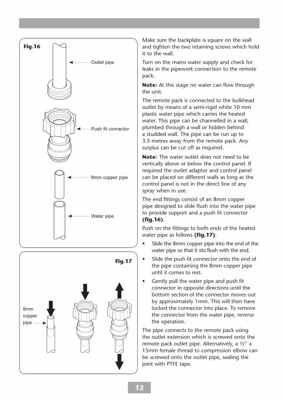
The end fittings consist of an 8mm copper pipe designed to slide flush into the water pipe to provide support and a push fit connector (fig.16).
Push on the fittings to both ends of the heated water pipe as follows (fig.17):
• Slide the 8mm copper pipe into the end of the water pipe so that it sits flush with the end.
• Slide the push fit connector onto the end of the pipe containing the 8mm copper pipe until it comes to rest.
• Gently pull the water pipe and push fit connector in opposite directions until the bottom section of the connector moves out by approximately 1mm. This will then have locked the connector into place. To remove the connector from the water pipe, reverse the operation.
The pipe connects to the remote pack using the outlet extension which is screwed onto the remote pack outlet pipe. Alternatively, a ½” x 15mm female thread to compression elbow can be screwed onto the outlet pipe, sealing the joint with PTFE tape.
Outlet pipe
Push fit connector
8mm copper pipe
Water pipe
8mm copper pipe
Fig.16
Fig.17

13
Fit the clear plastic PRD tube through the can outlet pipe boss situated at the rear of the outlet pipe (fig.26) and push firmly on to the PRD outlet.
The other end of the PRD tube needs to be directed to a suitable and visible waste.
Note: Check the correct tubes have been used as they are similar in diameter and length (the PRD tube is clear).
IMPORTANT: Do not bend either the PRD tube or heated water pipe sharply as they will kink and restrict the water flow. If a tight bend is required in the heated water pipe cut the pipe and rejoin with standard 10 mm elbow compression fittings.
Insert a 25 mm length of 8 mm copper pipe (four are supplied, but more may be required) to provide support for the plastic pipe under the olive ring. If possible, the connections should be accessible so that adjustment can be carried out when required.
Outletpipe
Pipeboss
Can
PRDoutlet
PRD tube
Fig.18

14
FITTING THE BULKHEADRoute the heated water pipe to the outlet position and push on the fittings as shown in Fig.16. Connect the heated water pipe to a ½” BSP x 15mm female thread elbow or straight coupler compression fitting (Fig.19).
Note: This fitting is not supplied as variations in installations requires selection of the most suitable fitting.
Screw the supplied male-thread connector into the female fitting (Fig.20) using PTFE tape to give a watertight joint.
Note: The male-thread connector supplied has a shoulder. If fitting into a flush wall, make an additional 8 mm allowance for this shoulder at the finished surface. The connector can be cut to size if required.
The threaded connector should protrude from the wall surface between 8 mm and 13 mm.
Make good the wall.
The bulkhead and its cover are supplied assembled. Separate the two halves by carefully prising apart at the smaller of the two elbow apertures.
Secure the elbow to the bulkhead body with the three screws supplied (Fig.21).
Screw the bulkhead assembly onto the threaded connector temporarily. Mark the position of the two fixing holes (Fig.22) securing the bulkhead to the wall.
Note: If screw thread protrudes too far out of the wall, it can be be cut to the correct length using a hacksaw.
Unscrew and remove the bulkhead assembly. Check the location of the pipe in the wall before drilling.
Fig.21
Fig.22
8mm − 13mm
Finished surface
Appropriatefitting
Heated waterpipe
Fig.19
Fig.20
15
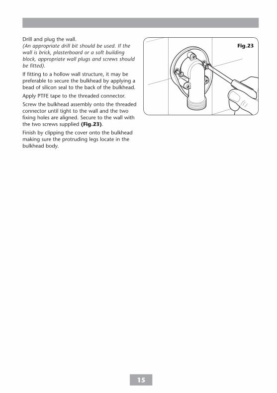
Drill and plug the wall.(An appropriate drill bit should be used. If the wall is brick, plasterboard or a soft building block, appropriate wall plugs and screws should be fitted).
If fitting to a hollow wall structure, it may be preferable to secure the bulkhead by applying a bead of silicon seal to the back of the bulkhead.
Apply PTFE tape to the threaded connector.
Screw the bulkhead assembly onto the threaded connector until tight to the wall and the two fixing holes are aligned. Secure to the wall with the two screws supplied (Fig.23).
Finish by clipping the cover onto the bulkhead making sure the protruding legs locate in the bulkhead body.
Fig.23

16
ELECTRICAL CONNECTIONSSWITCH OFF THE ELECTRICITY SUPPLY AT THE MAINS.
Fig.24 shows a schematic wiring diagram.
The cable entry points are shown in Fig.1.
The cable can be surface clipped, hidden or via 20 mm conduit.
Note: Conduit entry can only be from rear.
Route the cable into the shower unit and connect to the terminal block (Fig.25) as follows:
Earth cable to terminal marked E
Neutral cable to terminal marked N
Live cable to terminal marked L
IMPORTANT: Fully tighten the terminal block screws and check that no cable insulation is trapped under the screws. Loose connections can result in cable overheating.
Note: The supply cable earth conductor must be sleeved. The outer sheath of the supply cable must be stripped back to the minimum.
The supply cable must be secured either by routing through conduit or in trunking or by embedding in the wall, in accordance with current IEE regulations.
The use of connections within the unit, or other points in the shower circuit, to supply power to other equipment i.e. extractor fans, pumps etc. will invalidate the guarantee.
LN E
T300si
12
3
5
7
6
4
inletoutlet
9
8
10
11
Terminalblock
Fig.24
Fig.25
1 Terminal block 2 Earth post 3 Transformer 4 Motor 5 Thermal cut-out (main) 6 Control panel PCB
7 Remote pack PCB 8 Control cable 9 Elements 10 Solenoid valve 11 Thermal cut-out
(outlet)
Note: The elements on UK models are to 240V specification and will give a lower kW rating if the voltage supply is below 240V.

17
FITTING THE CONTROL PANEL BRACKET
Align the supplied fixing template (Fig.8) with the 15 mm control cable hole already drilled. Mark the four fixing holes marked ‘A’ on the template. Drill and plug using the plugs supplied, or suitable cavity fixings.Using the screws supplied, secure the mounting bracket to the wall (Fig.26).
Note: The mounting bracket must be fitted on the surface of the tiles.
The control panel is connected to the remote pack by means of a supplied length of control cable complete with a plug at either end. Either end of the cable can be plugged to the remote pack PCB (Fig.27) or the control panel PCB.
Cable entry into the control panel is via the opening on the back of the main body of the control panel. Remove the two screws and remove the access panel (Fig.28) to reveal the connector socket.
Cable entry into the remote pack is through one of the built in cut-outs.
Remove the protective dust covers from both ends of the control cable.
Once the cable has been plugged into the socket inside the control panel, refit the access panel, making sure the cable exits through the slot at the bottom corner of the access panel (Fig.29).
IMPORTANT: Leave enough free play in the cable to allow for future removal of the control panel for servicing purposes.
Make sure the cable clamp in the remote pack is used to secure the control cable (Fig.30).
DO NOT switch on the electricity supply until the cover on the remote pack and control panel have been fitted.
WARNING!
Under no circumstance should the control cable be extended or
shortened, as not only will it impair the performance of the shower but will also invalidate the guarantee.
Socketfor controlcable
Controlcableclamp
Controlcable exit
Fig.27
Fig.28
Fig.29
Fig.26

18
FITTING THE CONTROL PANELHook the control panel over the lugs on the mounting bracket (Fig.31) and slide down into place, making sure the control cable does not get trapped.
Secure in place with the single screw at the bottom of the control panel (Fig.32).
Note: To remove the panel once fitted, remove the single retaining screw, and lift off from the wall bracket lugs.
FITTING THE REMOTE PACK COVERRefit the trimplate and secure with the two screws.
Before replacing the cover, check on the PCB that the purge pin is located on its two pins – the factory set position, see Fig.34.
Locate the tags on the cover into the holes on the backplate and guide into position. Secure the cover in position with the three retaining screws.
Note: DO NOT fully tighten at this stage as the remote pack cover is fitted temporarily in order to carry out the commissioning procedure.
Fig.31
Fig.32
Socketfor controlcable
Controlcableclamp
Fig.30
WARNINGCOVER RETAINING SCREWS
ONLY the SUPPLIED SCREWS should be used. The use of none supplied screws WILL invalidate product specifications & warranty.

19
COMMISSIONING
The first operation of the shower is intended to flush out any remaining debris and to make sure the heater unit contains water before the elements are switched on. This operation must be carried out with the flexible hose screwed to the bulkhead outlet but WITHOUT the showerhead attached.
Make sure the outlet of the flexible hose is directed to waste.
Partially turn on the water supply to the shower and then turn on the electricity supply at the mains supply and to the shower at the isolating switch.
The Start/Stop button surround immediately lights up and remains lit while all four LED indicators will light up in sequence alternating between the ‘high’, ‘economy’, ‘cold’ and ‘low pressure’. This flashing sequence lasts about twenty seconds. All lights will then go out except the Start/Stop surround indicating the power is on to the unit.
Press the Start/Stop button (Fig.33) and the ‘cold’ indicator will light, while at the same time the ‘low pressure’ indicator will flash. Water will start to flow from the flexible hose.
It will take about thirty seconds for a smooth flow of water to be obtained while air and any debris is being flushed from the shower.
When a smooth flow of water is achieved, turn the water supply fully on and allow it to run for about two minutes.
Once the flushing out has been completed, press the Start/Stop button and SWITCH OFF THE ELECTRICITY SUPPLY to the shower at the isolating switch.
Fig.33
WARNING!
Before normal operation of the shower it is essential that the commissioning and purge pin
procedures are correctly completed.
20
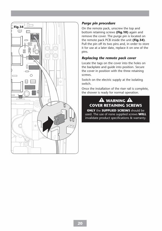
Purge pin procedureOn the remote pack, unscrew the top and bottom retaining screws (Fig.10) again and remove the cover. The purge pin is located on the remote pack PCB inside the unit (Fig.34). Pull the pin off its two pins and, in order to store it for use at a later date, replace it on one of the pins.
Replacing the remote pack coverLocate the tags on the cover into the holes on the backplate and guide into position. Secure the cover in position with the three retaining screws.
Switch on the electric supply at the isolating switch.
Once the installation of the riser rail is complete, the shower is ready for normal operation.
Fig.34
WARNINGCOVER RETAINING SCREWS
ONLY the SUPPLIED SCREWS should be used. The use of none supplied screws WILL invalidate product specifications & warranty.

21
OPERATING THE SHOWER IMPORTANT: Make sure the commissioning procedure has been carried out. Failure to do so will damage the unit and invalidate the guarantee.
When the electricity supply to the shower is switched on via the double pole isolating switch, the Start/Stop button surround immediately lights up and remains lit while the shower runs through a start-up routine.
All four LED indicators will light up in sequence alternating between the ‘high’, ‘economy’, ‘cold’ and ‘low pressure’. This flashing sequence lasts about twenty seconds and will occur every time the power is switched on at the isolating switch. All lights will go out except the Start/Stop surround indicating that power is on to the unit. The shower is now ready for normal operation.
To start the showerPress the Start/Stop button and immediately the high button LED will light and water will begin to flow.
To stop the showerPress the Start/Stop button. The phased shutdown will start and water will cease to flow after a few seconds. Note the button surround will still be lit.
To use the control buttonsThere are three control buttons − high, cold and economy − as shown in Fig.35.
The upper button is a high power setting which allows the highest flow achievable for your preferred temperature. This setting should normally be regarded as optimum shower performance throughout the year. Temperature adjustment at this setting is via the temperature control.
The centre button is an economy setting for using less power when the ambient mains water temperature is high during hot months. Temperature adjustment at this setting is via the temperature control.
Start/stop button
High power button
Economy power button
Cold only button
Temperature control
WARNING!
After any servicing of mains water supply, always make sure the unit is started on COLD in order to purge
any air in the pipework.
Fig.35

22
Note: If the stated flow rate required for the unit cannot be met due to low water pressure, it will be necessary to operate the unit on this setting during the warmer months because of flow rate limitations entering the unit.
The lower button is for cold water only. Adjusting the temperature control at this setting will only change the force of the water from the shower-head (it will not alter the water temperature).
To adjust the shower temperatureThe water temperature is altered by increasing or decreasing the flow rate of the water through the shower using the temperature control (Fig.35).
After obtaining your preferred showering temperature, the number can be remembered and left as the normal setting and should only need to be adjusted for seasonal changes in ambient water temperature.
Note: The preferred number on ‘economy’ will give a different temperature to the same number position on ‘high’.
To decrease the shower temperatureTurn the temperature control anti-clockwise (Fig.36). This will increase the flow of water through the shower and is indicated by lower numbers.
To increase the shower temperatureTurn the temperature control clockwise (Fig.37). This will decrease the flow of water through the shower and is indicated by higher numbers.
CAUTION: It is advisable to be certain that the showering temperature is satisfactory by testing with your hand before stepping under the showerhead. There will always be a time delay of a few seconds between selecting a flow rate and the water reaching the stable temperature for that flow rate.
CAUTION: It is recommended that persons who may have difficulty understanding or operating the shower controls should not be left unattended while showering. Special consideration should be given to young children and the less able bodied.
Fig.36
Fig.37
WARNING:
The shower will ALWAYS start on the “HIGH” setting even if it was last used and switched off on the “ECONOMY” setting.
When the shower is in use, DO NOT STOP and then RESTART the shower while under the showerhead. The shower will default to the “HIGH” setting and a slug of HOT water will be discharged from the showerhead.

23
OPERATING FUNCTIONS
Power on indicator (Fig.38)
When the electricity supply to the shower is switched on at the isolating switch, the start/stop button surround will light.
Low pressure indicator (Fig.38)
If this indicator flashes, it means the water pressure has fallen below the minimum required for correct operation of the shower, resulting in the low pressure cut-out operating. This switches off power to the heating elements preventing any maintained temperature rises (water will continue to flow) while at the same time the ‘cold’ indicator will light.
When enough water pressure returns, the ‘low pressure’ and ‘cold’ indicators both extinguish and the power will automatically be restored to the power setting at the time of interruption.
Selector mode indicators (Fig.38)
Next to each control button there is an LED which lights up when the button is pressed, visually showing which shower mode is in operation.
Phased shutdownIn use, when the Start/Stop button is pressed, power is switched off to the elements. Water continues to flow for a few seconds, flushing out the system.
Note: The shower should always be switched off in this manner before isolating at the double pole isolating switch.
Overheat cut-outDuring normal operation if an overheat temperature is sensed, power to the elements will be reduced. Water will continue to flow. When the temperature has cooled sufficiently, power to the elements will be automatically restored to the previous setting at the time of interruption.
Note: In normal use, it is in order to leave the water supply permanently on to the shower unit, but as with most electrical appliances, the unit must be switched off at the isolating switch when not in use.
Start/stop button
High power button
Economy power button
Cold only button
Temperature control
Fig.38

24
Safety cut-outThe unit is fitted with a non-resettable over-temperature safety device. In the event of abnormal operation which could cause unsafe temperatures within the unit, the device will disconnect the heating elements. It will require a visit from a qualified engineer to determine the nature of the fault and replace the safety device, once the unit has been repaired.
CLEANINGDo not use abrasive or solvent cleaning fluids. The shower unit, riser rail, hose, etc. should be cleaned using a soft cloth and warm water.
Before cleaning, turn the unit off at the isolation switch, to avoid the unit being accidentally switched on.
IT IS IMPORTANT TO KEEP THE SHOWERHEAD CLEAN TO MAINTAIN THE PERFORMANCE OF THE SHOWER. The hardness of the water will determine the frequency of cleaning. For example, if the shower is used every day in a very hard water area, it may be necessary to clean the showerhead on a weekly basis.
Before replacing the showerhead on the hose, it is advisable to direct the hose to waste, turn the temperature control fully anti-clockwise and press the COLD button. This operation will flush out any loose scale deposits in the unit. Stop after about thirty seconds and replace the showerhead.
WARNING!
DO NOT use ‘powerful’ abrasive or solvent cleaning fluids when
cleaning the shower as they may damage the plastic fittings.

25
Inletfilter
Fig.39
INSTRUCTIONS FOR INSTALLERS AND SERVICE ENGINEERS ONLY
Cleaning the filterIt is recommended that the filter is periodically cleaned in order to maintain the performance of the shower. It is essential that this operation is carried out by a competent person.
SWITCH OFF THE ELECTRICITY SUPPLY AT THE MAINS.
The inlet filter is situated inside the solenoid inlet (Fig.39).
To gain access to the filter remove the cover then disconnect and remove the compression fitting. Also, depending on the incoming pipework arrangements, if there is not enough slack in the pipework, it could mean the removal of the unit from the wall.
When cleaning the filter, DO NOT use a sharp object, as it will cause damage. It is preferable to use an old toothbrush or similar.

26
SPARE PARTS Ref. Description Part No.
1 Terminal block 8.5kW & 9.5kW 82200930
2 Transformer 22005020
3 PCB − remote pack 8.5kW & 9.5kW 7072570
4 Thermal cut-out (main) 22009860
5 Heater can assembly 8.5kW P84500300 9.5kW P84500290
6 Stabiliser valve assembly 82600780
7 Stepper motor 82300170
8 Control cable clamp 7051655
9 Solenoid valve 83304130
10 Outlet pipe assembly 85000130
11 Trimplate 7051754
12 PRD & ‘O’ ring 83301330
13 Remote pack cover 85200030
14 PCB control panel 7072569
1
13
2
34
5
6
7
8
9
10 11
14
12

27
SPARE PARTS Ref. Description Part No.
15 Control panel assembly chrome 87400040
16 All thread fitting 7032915
17 Control panel mounting bracket 7012512
18 Bulkhead 85500230
19 Female Coupler 22010200
− 25mm Copper Pipe 7021272
− PRD tube (clear) 22001310
− Heated water pipe 22010200
− Inter-connecting cable 82300900
− Wire set 83306410
18
17
16
15
19
20

28
1 Shower inoperable, no water flow.
2 Water too hot.
3 Water temperature cycling hot/cool at intervals.
4 Water too cool or cold.
1.1 Interrupted power supply.
1.2 Unit malfunction.
2.1 Not enough water flowing through the shower.
2.2 Blockage in supply.
2.3 Increase in ambient water temperature.
3.1 Heater cycling on outlet thermal cut- out.
4.1 Too much flow.
4.2 Water pressure below minimum stated on rating label.
1.1.1 Blown fuse or circuit breaker. Check supply. Renew or reset fuse or circuit breaker. If it fails again, consult a qualified electrician.1.1.2 Power cut? Check other appliances and if necessary, contact local Electricity Supply Company.
1.2.1 Have unit checked. Ring Customer Service.
2.1.1 Increase the flow rate via temperature control.2.1.2 Blocked showerhead − clean or replace blocked sprayplate / cartridge.
2.2.1 Check if stop taps are fully open. Check if blockage in inlet filter.
2.3.1 Switch to economy power setting and readjust flow rate to give required temperature.
3.1.1 See 'Water too hot' causes 2.1, 2.2 and 2.3 and their action/cures. If it continues, contact Customer Service.
4.1.1 Reduce the flow rate via temperature control.
4.2.1 Check low pressure indicator. If lit, continue with remainder of checks. If not lit, see 4.1 & 4.4.4.2.2 Is water supply mains or tank fed ?4.2.3 If tank fed, replumb to mains water supply or see 4.2.5.4.2.4 If mains fed, make sure that mains stopvalve is fully open and that there are no other restrictions in the supply while shower is in use, or see 4.2.5.4.2.5 Fit a pump to give minimum pressure – contact Customer Service for advice.
FAULT FINDINGIMPORTANT: Switch OFF the electricity at the mains supply and remove the circuit fuse before attempting any fault finding inside the unit.
Problem/Symptom Cause Action/cure

29
Note: Identify cause of operation before fitting new PRD unit. When fitting a new PRD, follow the commissioning procedure.
It is advised all electrical maintenance/repairs to the shower should be carried out by a suitably qualified person.
5 Cold indicator light on and low pressure indicator light flashing.
6 Temperature varies from normal to cold intermittently during showering.
7 Pressure relief device has operated (water ejected from PRD tube).
4.3 Reduction in ambient water temperature.
4.4 Electrical malfunction or safety cut-out has operated.
5.1 Purge pin not placed correctly.
5.2 Low water pressure.
6.1 Water pressure dropped below minimum required (indicator flashing).
7.1 Blocked showerhead.
7.2 Twisted/blocked flexible shower hose.
7.3 Showerhead not removed while commissioning.
4.3.1 Switch to full power setting and readjust the flow rate via the temperature control to give required temperature.
4.4.1 Have unit checked by suitably qualified electrician or contact Customer Service.
5.1.1 Isolate the electricity supply. Remove remote pack cover and place purge pin on one pin only.
5.2.1 Wait until the water pressure resumes to normal (low pressure indicator extinguishes).5.2.2 Check if stop taps are fully open. Check if blockage in supply pipe.
6.1.1 Wait until the water pressure resumes to normal (low pressure indicator extinguishes).
7.1.1 Clean or replace blocked sprayplate or cartridge and then fit a new PRD.
7.2.1 Check for free passage through hose. Replace hose if necessary and then fit new PRD.
7.3.1 Fit new PRD. Commission unit with showerhead removed.
FAULT FINDING (continued)
Problem/Symptom Cause Action/cure

Vado Wedmore Road Cheddar Somerset BS27 3EB
Vado is a division of Norcros Group (Holdings) Limited
VADO reserve the right to change product specification without prior notice. E&OE. © VADO 2013
Customer Service: 0844 980 0748
www.vado-uk.com
Extended Warranty AVAILABLE NOW. Call 0844 980 0748 for more details.
VADO STANDARD GUARANTEE
UK SERVICE POLICYIn the event of a product fault or complaint occurring, the following procedure should be followed:1. Telephone Customer Service on 0844 980 0748 having available,
your details including post code, the model number and power rating of the product, together with the date of purchase and, where applicable, details of the particular fault.
2. If required, the Customer Service Advisor will arrange for a quali�ed engineer to call.
3. All products attended to by a Vado service engineer must be installed in full accordance with the Vado installation guide applicable to the product. (Every product pack contains an installation guide, however, they can also be bought via our Customer Service Spares Department).
4. Our engineer will require local parking and if a permit is required this must be available to the engineer on arrival at the call.
5. It is essential that you or an appointed representative (who must be over 18 years of age) is present for the duration of the service engineer's visit. If the product is in guarantee you must produce proof of purchase.
6. Where a call under the terms of guarantee has been booked and the failure is not product related (i.e. scaling and furring, incorrect water pressure, pressure relief device operation or electrical/plumbing installation fault) a charge will be made. A charge will also be issued if nobody is at home when the service engineer calls or adequate parking/permit is not available.
7. If the product is no longer covered by the guarantee an up front �xed fee will be charged before the site visit.
8. Should proof of purchase not be available on an “in-guarantee” call, or should the service engineer �nd that the product is no longer under guarantee, the engineer will charge the same �xed price and the customer will be expected to pay the engineer before he leaves. If payment is not made on the day an administration charge will be added to the �xed charge.
9. If a debt is outstanding from a previous visit, or from any other Vado purchase, Vado reserves the right to withhold service until the debt has been settled.
10. Vado takes the health, safety and wellbeing of its employees very seriously and expects customers to treat all staff members with respect. Should any employee feel threatened or receive abuse, either verbally or physically, Vado reserves the right to withhold service and will support the employee with a legal prosecution.
Replacement Parts PolicyAvailability: It is the policy of the manufacturer to maintain parts availability for the duration of production and a period of �ve years thereafter, in accordance with industry standards.Spare parts are available via our website, www.vado-uk.com, or by telephoning Vado Customer Service Spares Department. Payment should be made by credit/debit card (excluding American Express or Diners Card). Payment can also be made by pre-payment of a pro forma invoice by cheque or money order. Telephone orders are based on information given during of the call. Before contacting Vado, please verify your requirements using the information contained in the supplied user guide. Vado cannot accept liability for incorrect part identi�cation.
For the latest Terms & Conditions, please see: www.vado-uk.com
With the exception of accessories, Vado guarantee the product against all manufacturing defects for a period of 2 years for domestic use only, from the date of purchase, provided that it has been installed by a competent person in full accordance with the �tting instructions.
All accessories such as shower heads, hoses and riser rails carry a 1 year parts only guarantee against manufacturing defects.
Any part found to be defective during this guarantee period we undertake to repair or replace at our option without charge so long as it has been properly maintained and operated in accordance with the operating instructions, and has not been subject to misuse or damage. This product must not be taken apart, modi�ed or repaired except by a person authorised by Vado. This guarantee applies only to products installed within the United Kingdom and does not apply to products used commercially. This guarantee does not affect your statutory rights.
What is not covered:1. Breakdown due to: a) use other than domestic use by you or your resident family; b) wilful act or neglect; c) any malfunction resulting from the incorrect use or quality of electricity, gas or water or incorrect setting of controls; d) failure to install in accordance with the installation guide.
2. Claims for missing parts once the product has been installed.
3. Repair costs for damage caused by foreign objects or substances.
4. Total loss of the product due to non-availability of parts.
5. Compensation for loss of use of the product or consequential loss of any kind.
6. Call out charges where no fault has been found with the appliance.
7. The cost of repair or replacement of pressure relief devices, showerheads, hoses, riser rails and/or wall brackets, isolating switches, electrical cable, fuses and/or circuit breakers or any other accessories installed at the same time.
8. The cost of routine maintenance, adjustments, overhaul modi�cations or loss or damage arising there from, including the cost of repairing damage, breakdown, malfunction caused by corrosion, furring.
9. Call out charges where the water supply cannot be isolated, this includes consequential losses arising from unserviceable supply valves.