Embed Size (px)
Citation preview
VACUUM SYSTEMS FOR
THE COLLECTION OF SOLID WASTES
PETER H. LUITEN. P. E. Engineering-Science, Inc.
Arcadia, California
ABSTRACT
This presentation is intended to provide some background on the history, technical aspects and experience with vacuum systems for refuse collection. Emphasis is placed on the differences in purpose, engineering design and performance of the basic types available. Engagement of a qualified consultant is recommended.
GENERAL DISCUSSION
Historically, almost 80% of the mul ti-billion dollar solid waste management cost in the U.S. has been spent on collection of the waste, the balance being the cost of the actual disposal. The disposal costs may be wholly or partially defrayed by new technologies in recycling, but optimized collection is of equal importance to reduce collection costs and to improve the environment at specific facilities or building complexes.
A new collection method introduced in recent years is the vacuum collection system that automatically transports refuse to a central terminal or treatment facility. The advantages of these systems over conventional trash collection are conspicuous wherever large quantities of trash are generated. Local trash accumulation areas are no longer needed and the appearance, hygiene, traffic patterns and general environment of the facilities are greatly improved. Their annual cost is almost inflationproof because the systems do not depend on manual labor for the transport of bags, cans or trash
469
bins to storage areas or compactors. With these convincing arguments, one might ex
pect every new development to acquire such an installation without delay along with the sewer system, the water supply and other standard utilities. Indeed, thousands of enthusiastic initial inquiries are made but, in many cases, the capital investment cost of a substantial system becomes an obstacle. The procurement does not materialize, or the installation is made with cost-saving compromises that later make it impossible for the system to live up to its expectations.
Residerrtial system applications require a large high-density project and a long-term concern with the facilities served. So far, such systems have been acquired only by builders who plan to own and operate the development for many years. In Europe, this own-and-operate practice prevails and dozens of these collection systems now exist in apartment complexes of 1000 to SOOO dwelling units. Most U.S. developers of apartment complexes have been private enterprises who plan to sell the complex shortly after occupancy. Initial costs are the prime consideration and they are not interested in investing capital funds to reduce future operating costs for someone else.
Most vacuum collection systems in the U.S. have, so far, been installed in hospitals. With waste generation averaging almost 7 kg (IS lbs) per bed per day, the systems become in teresting for even a few hundred beds. For 400 to 1000-bed hospital complexes, the operating cost savings become extremely attractive. Besides, the hygienic improve-
ments and reduced labor-dependency heavily favor the systems's use for hospitals.
Commercial applications must have a short payout period, preferably combined with a lease-back arrangement to obtain tax advantages. Long-term capital recovery is acceptable only when the system greatly enhances the esthetics and design freedom, such as in large recreational parks or futuristic commercial developments.
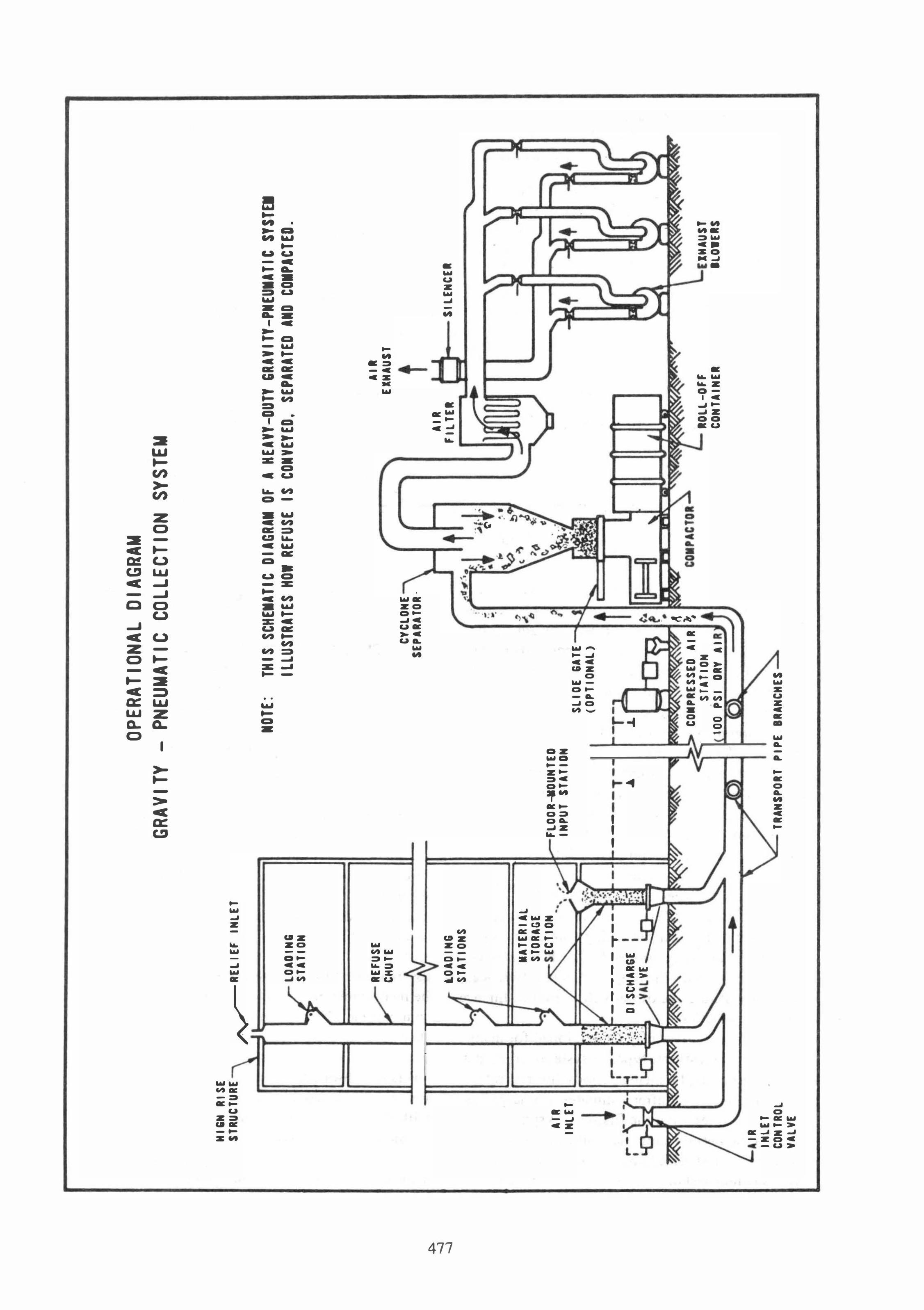
General descriptions of vacuum refuse collection systems are available in manufacturers' brochures and in published magazine articles such as Refs. [1,2,3,4,5 & 6]. This presentation intends to review the technical aspects of these systems. To simplify the discussion, they have been grouped into two categories, one being the multi-purpose, light-duty, full-vacuum systems originally developed in the u.s. for laundry collection. The other group includes the larger, heavy-duty, gravity-pneumatic systems developed in Sweden for th� collection of loose refuse. Competing system suppliers tend to "borrow" ideas from each other and the system concepts may overlap at times, but the grouping is historically factual and emphasizes that different systems are needed for different purposes.
The U.S. developed systems were originally introduced by Eastern Cyclone Industries, Fairfield, New Jersey. Other companies offering various versions of this light-duty system include Montgomery Industries, Inc., Jacksonville, Florida; the Automatic Tube Co., San Rafael, California, and a few other emerging competitors. The systems pased on the original Swedish concept are marketed in the U.S. by A V AC Systems Inc., of Mountainside, N.J. (which company acquired the product line in 1975 from a division of Aerojet-General Corporation), and by S. F. Air Control, Inc., Greenwich, Conn.
LIGHT-DUTY SYSTEMS
Vacuum systems to collect hospital laundry were developed in the United States during the late 1950's. These systems consist of lateral and vertical sheet-metal chutes with the air intakes at the tops of the chutes. They are referred to as fullvacuum systems when all chutes are exposed to the negative pressure.
Double-door loading stations at random locations on various floors permit loading a bag of laundry between the inner door and the outer door. Upon activation of the system, the bags enter the transfer chute, one at a time, by the
automatic opening of the inner station-door. Each bag is transported to a central collector from which it drops out by the opening of hinged doors. The re-closing of these doors prepares the system
for transporting the next bag, and so on. During the past eight years, many variations
have been added to permit the use of these systems for solid waste collection, to increase the transport capacity, to reduce the waiting time for janitorial personnel at loading stations, to enable their use with standard vertical chutes as a gravityvacuum system, and to combine them with material-handling fans for shredded waste transport. They generally utilize 400 mm (16-inch) dialJleter sheet-metal transfer chutes with wall thicknesses sometimes as low as 18 U.S. gauge (1.2 mm. or 0.05 inch), and have inexpensive, box-type, material collectors. They use high-volume, low-pressure, high-horsepower suction fans and provide nominal filtration of the discharged air.
It is estimated that some 60 of these systems have been installed in U.S. hospitals to handle laundry, or laundry and waste. In the earlier versions of this system, the laundry bags and packages of trash were transmitted through the same transfer station and chutes. Pushing of a control button at the station would program a branch-line diverter valve downstream, which would direct the laundry or the trash bags to their respective collectors through separate branch lines. This practice caused problems by human errors, diverter-valve sticking and breakage of trash bags. It is now generally avoided by using separate stations, chutes and ducts for laundry and trash.
Maximum loads are normally specified as bags not exceeding 50 cm x 75 cm (20-inch x 30-inch) when flat, with a weight maximum of 13.6 Kg (30 lbs). Transfer distances are limited by the vacuum levels of the single-stage fans and the permissible vacuum on the sheet metal ducts. Transfer lengths exceeding 300 meters (1000 feet) will require larger duct diameters and heavier wall thicknesses than usually specified.
During the past two years, installation contracts have also been awarded for apartment buildings and a State-Government complex. Their acceptance has been positively influenced by the relatively low acquisition cost.
HEAVY-DUTY SYSTEMS
In the early 1960's, the prinCiples of vacuum
transport were applied for the first time to the col-
470
lection of unclassified solid waste in a multi-story hospital at Solleftea, Sweden. The success of the system prompted the development of a large vacuum collection system for residential refuse in a new 11 OO-unit, multi-story housing complex at Sundbyberg, a suburb of Stockholm, Sweden, which was activated in 1967.
Since that time, some 55 heavy-duty systems of this type have been installed in the Scandinavian countries as well as in England, Germany, France, Australia, Venezuela, Russia and the United States. They include multi-million dollar residential systems collecting the waste from thousands of apartments with up to 110 gravity chutes per system; a recreational park system with two miles of transfer piping; systems that daily handle many tons of federal Government paper waste; a system collecting broken glass in a beer brewery and a number of systems collecting hospital wastes. Power requirements have ranged from 75 to 600 hp. . In these gravity-pneumatic type systems, waste
material is dropped without restrictions into singledoor loading stations of standard gravity-type chutes. The system automatically accepts the refuse that accumulates at the bottom of each chute by the intermittent opening of a specially designed slide-valve below the chute. This permits the material to drop into the air stream of the transfer pipe below. The systems can serve a large number of gravity chutes in sequence, at intervals as short as 20 seconds. The resulting high transfer capacity permits programming the operation of such systems for a number of short periods each day. This is particularly beneficial for energy conservation and for installations with peak-hour demands.
The heavy-duty systems will accept unsorted household, hospital or commercial trash including broken glass, metal cans and other abrasive components, without packaging or bagging. The crosssection of the transported material is limited by the dimensions of the loading doors, and by the diameter of the chute valves and transfer piping which has averaged 500 mm. (20 inches).
The lateral transfer piping network is generally branched with each branch having a normally closed air-intake valve at its most remote point. Sequential automatic opening of each air intake establishes air flow in the particular branch, which permits evacuation of the chutes on that branch.
The systems are characterized by their long lifeexpectancy, low maintenance requirements, large transfer capacity and minimum power consump�ion. Coated-and-wrapped welded steel, or cast
iron transfer piping is used for inaccessible or buried locations. Special fittings and elbows assure smooth material flow and provide long-term resistance against internal erosion. Multi-stage blowers create the relatively high vacuum levels required for the refuse transport over distances up to several miles and the high performance discharge-air filters. Their initial cost is bound to be higher than for light-duty systems.
Collection terminals are designed to retain, or to automatically transfer, the entire quantity of loose refuse collected within one operating cycle without interruption of the collection process itself. The terminal may include incinerators or other waste treatment equipment but, in most cases, the collected refuse is automatically compacted into rolloff containers for transport to ultimate disposal facilities. For the large residential systems, remotely controlled container positioning and transfer equipment is provided as part of the total installation.
ENGINEERING PRINCIPLES
Pneumatic conveying of homogeneous materials in relatively small particle sizes has been an industrial practice for many decades. Fields of application have included the transport of hundreds of different materials ranging from grains, cement, wood chips, sand and minerals to uniform scrap from light industrial processes. Engineering standards for positive-pressure, negative-pressure or combined systems are well known and available in engineering handbooks or publications [Ref. 7, 8 & 9].
For refuse collection use, the negative-pressure or vacuum systems are the most applicable because of their ease of loading and because the purpose of the system is to transport material from multiple loading points to a central collection terminal. Engineering principles are similar to other pneumatic conveying systems in that the system power demand is calculated by combining the air pressure drop with refuse friction-and-acceleration factors. However, velocities, vertical transport aspects and components design must be adjusted to cope with the extreme variety in densities, shapes, dimensions and loading methods of wastes. In contrast with
471
the pneumatic transport of homogeneous materials, the collection systems for loose refuse may be considered to move the material in three different ways, all of which may occur sim�ltaneously:
I) Low-density components are separated from
the load by the air stream and are carried forward at velocities approaching the air velocity.
2) Bulky, medium-density items including ref--
use in bags, are transported at lower speeds by the differential-pressure force of the air that bypasses the bulky object. Bags that essentially fill the transfer pipe will be subjected to an accelerating force equal to the cross-sectional area of the pipe multiplied by the negative-pressure at which the blower operates under throttled air flow. This transport mode has been typical for the light-duty type systems.
3) Loose, heavy components in the trash will not travel by normal air velocities but will be pushed towards the collector intermittently by other materials that pile up against them and create a temporary throttling of the air flow. Their transport to the collection terminal may take several operating cycles but it is readily accomplished with proper system design. Rocks, tools, and even Christmas trees and construction wastes have been successfully collected when mixed with the other refuse handled by the heavy-duty systems.
Air velocities for these types of systems have averaged around 24 meters per second (80 ft/sec.). The light-duty systems recently seem to have used higher velocities, possibly to compensate for the limited vacuum levels that can be tolerated. In the heavy-duty systems the air velocities are often decreased to reduce erosion, or whenever the systems are used for the collection of material with predictable characteristics such as laundry.
Other operational differences relate to the method of refuse loading. With the light-duty systems, refuse is introduced at low loading rates. Even in the gravity-vacuum version of these systems, the loading from the gravity chutes is accomplished by a metering device that limits the loading rate to match the transfer and collecting capacity of the system. For systems with high peak-loads such as in residential complexes, low loading-rates are impractical or require excessive operating time and power costs.
In the heavy-duty gravity-pneumatic systems a slug of material weighing up to two-hundred pounds is charged into the air stream within a few seconds by the opening of the chute valve, intermittently followed by similar chute-loads while the first load is still traveling within the transfer piping. The rapid acceleration of such loads from the atmospheric chutes into the pipe is made possible by maintaining a minimum vacuum level at all points of the transfer piping of about 25 mm (1
472
inch) Hg-column during an operating cycle. Where chutes are close to the end of a transfer line this is accomplished by throttling the air intakes. The pressure differential also permits the use of short branch lines to the main transfer line without needing separate air inlets for these branches.
Conversely, piping vacuum levels below loading chutes at the downstream ends of long branches will become too high for convenient unloading of the chutes. For instance, for a transfer distance of 3.2 km (2 miles), which is a reasonably practical transfer distance limit for this system, the operating vacuum of the multi-stage blower may well approach one-half atmosphere to compensate for the air-and-material pressure drop. To operate such chutes, auxiliary air intakes are provided in the transfer pipe nearby to prevent excessive vacuum levels. The programmed opening of these air intakes also throttles the air discharge at the terminal to assure that the blowers will operate in their normal capacity range, and to avoid excessive fluctuations in air flow and power consumption.
In systems handling loose trash, the light-weight components such as newspapers, computer printouts and broken plastic bags float like "gossamers" and must be prevented from being sucked into the air filters or the blowers. They will readily block even large exhaust-air screens in the collector which would decrease the transport air velocity to where the refuse can no longer be carried by the air stream. Effective modified-cyclone separators are mandatory to prevent this from happening.
For extensive systems with large peak-load demands the rates of refuse depositing in the chutes must be determined and correlated with I) the number of chutes, 2) the chute-unloading frequencies, 3) the refuse travel-distances in the transfer pipes, 4) the system capacity in terms of refuse loads traveling simultaneously and 5) the refuse holding capacity, or the refuse-transfer rate to the compactor, at the terminal. When waste generation rates are established, all other factors are subject to change by trade-off analyses. For systems serving over 60 chutes and transferring more than 6 tons per hour over distances averaging 1.6 km (1 mile) or more, dual terminal equipment will be recommended serving two half-size subsystems simultaneously. Such dual equipment would be arranged so that each assembly could serve either subsystem, as stand-by.
The systems use an average of 300 cubic meter (10,000 cubic feet) of transport air per minute which requires correctly located outside air intakes.
Some light-duty hospital systems withdraw this air directly from the loading areas to reduce the system cost. This may disrupt the ventilating balance of the building and cause a waste of conditioned air. Independent air supplies are much preferred. In addition, relief-air dampers must be provided for enclosures that are periodically exposed to the system vacuum, such as chute-discharge valve rooms.
The waste storage sections of the chutes should be located at basement or service floor levels that permit access for manual trash removal in case the system operation is temporarily interrupted for any reason. The sections should have easily removeable access panels.
SYSTEM LIMITATIONS
The material to be collected must be relatively dry. Materials such as food wastes and wet garbage tend to stick to the loading station and the chute wall which will cause unsanitary conditions or requires daily cleaning. Food wastes, therefore, should be packaged in paper or plastiC strong enough to survive the initial drop into the loading chute.
Once the waste enters the lateral transfer pipes, breakage of the package is not important as the pipe walls are self-cleaning due to the scouring action of the high-speed refuse. After several years of operation, a typical residential waste system pipe interior has a dark metallic surface, has no objectionable odor and shows a narrow, sugar-like trail of small glass particles at the pipe bottom.
Correct design of fittings, joints, and pipe slopes as well as a built-in assurance of air-flow continuity will prevent system clogging, but inadequate construction supervision and system abuses have caused problems in the past and must be anticipated. Manholes are provided in the transfer pipe near critical fittings to allow access to pipe blockages should these occur. Such obstructions are removed by breaking them up with a pipe-rodding tool and re-establishing the air flow, similar to the methods and equipment used for restoring flow in sewer lines.
Very light wastes in sealed plastic bags may not drop down through vertical chute when the valve opens because the slight vacuum exposure may balloon the bag to where it hangs up on the side walls. The added weight of other trash, or cutting a hole in the bag before loading will remedy this.
Wet garbage may well weigh ten to fifteen times
473
as much as the equivalent volume of ordinary refuse so a chute load of garbage would create a slug too heavy to accelerate properly. The same applies to large quantities of broken glass, metals or similar high-density wastes. Cafeteria or restaurant kitchen wastes generated in large quantities should be loaded together with lighter refuse to prevent excessive load densities.
Pneumatic transfer of garbage mixed with dry refuse has been well demonstrated at a large recreational park installation, but this system required early replacement of the collector air-exhaust screens which corroded away due to the acidity of airborne liquids such as soft drinks.
Proper housekeeping at the collection terminal, and periodic cleaning of compactors and other components that are exposed to stationary garbage, is recommended. Organic refuse will ferment and cause odors if it remains too long in a container. Chemical additives may delay this process, but one most effective solution at a hospital system has been to maintain a low temperature at the terminal where waste accumulates for several days before the container is full enough for removal.
The size of certain waste items such as card board boxes, and crates is a definite system limitation. Attempts to force them will result in blocking the loading chute or the waste valve. If these types of refuse are to be handled, special loading-stationj shredder combinations are recommended. They use a low-speed, high-torque shredder that cuts and tears the material into smaller pieces. Such stations can be conveniently included to serve the specific areas where bulky wastes are generated. They could be connected by smaIler diameter branch lines.
OPERATIONAL CONTROLS
Trouble-free operation of a well-designed and properly installed system depends for the greater part on the automated control system. This starts the cycles as programmed and sequences all operations at the optimum time intervals. It prevents the next step from occurring if the previous step has not been completed correctly, or if something interferes with a forthcoming functioning of a system component. It announces such program interruptions audibly and visibly.
The control system may monitor from ten to a hundred conditions, depending on the size of the coIlection system. It relies on pressure, vacuum and flow-measuring devices for transport air control
and includes many micro-switches to indicate positions and conditions of waste valves, air valves, access doors, pneumatic cylinders, compactors, containers and other components. Monitoring examples are 1) proper closing of chute valves, 2) adequate air flow in pipe branch, 3) trash levels in chutes and cyclone, 4) adequate utility air pressure for pneumatic operators,S) closed position of any system access doors, 6) air-filter pressure drop, and similar functions.
A novel control system feature is used in the operation of systems having vertical chutes with diameters larger than the chute-valve. This will occasionally create loads too large to pass freely through the valve. When the control system senses that the valve is obstructed and can not close again, it re-opens the valve while simultaneously throttling the remote transport air intake to the pipe. Consequently, the waste load now is subjected to a large vacuum force which rapidly pulls the load into the pipe and the airstream. The valve closes again and the normal air intake is restored automatically. If the obstruction is too_solid to deform into the smaller opening, the control will try this procedure three times. If the obstruction remains, the controls will shut down the operation and announce at the central control panel that the cycle interruption needs personal attention.
Control system programming equipment should be very flexible and easily adjustable. Programs always have to be revised after system activation to suite the operational requirements. Multiple discharges of specific chutes may be required within one operating cycle for chutes with high wasteloading patterns. Alternate program tapes or patchpanels may be provided to adjust the cycle for recurring variations in operational demands.
Fire hazards are very low. All chutes, cyclones and storage silos are provided with automatic sprinklers. Chute valves should permit fire water drainage externally from the system, to a floor drain. In some hospital systems, the loading chutes have sensors that activate the collection cycle upon detection of smoke, so that smoldering material is removed automatically before flames occur. Wastes will not burn during transport and may even be completely extinguished in the pipe due to the cooling action of the high-velocity air.
EROSION EXPERIENCE WITH LOOSE,
UNSORTED REFUSE
Erosion of the transfer piping has not been evidenced with nonabrasive wastes, or when bottles,
cans and other abrasive components are separated from the waste before �ystem transport, or when unclassified refuse is deposited in heavy-wall (0.15 mm or 0.006 inch) plastic bags that are strong enough to survive the high-speed transfer. This bag· ging also simplifies the collector design because there is no need to separate light-weight, loose trash pieces from th.e air transport stream at the terminal.
However, the operational cost difference between this "survivable bagging" practice and transporting the refuse loose or in light-weight bags becomes enormous for large systems. For instance, for a residential collection system collecting one bag per day from say 2,000 apartments, some 730,000 bags are used each year. If substituting of special bags for the usual light-weight bags costs say $0.20 extra per bag, the annual operating cost ,would increase by $150,000 a year at current prices. This cost difference may well triple over the next 20 years with nominal inflation. If such a collection system would have a capital cost of say $1.5 million, this special bagging requirement alone would have the effect of doubling or tripling the actual cost of the system when the additional an· nual operating costs are capitalized as Present Worth. The same applies for hospitals, which use at least 2 bags per bed per day.
Thus, features such as erosion resistance, and the ability to effectively separate the transport air from light-weight refuse, are cost-effective investments for systems in large residential and hospital complexes because they eliminate the need for ex· pensive special bagging.
Abrasive erosion of the pipe wall was not anticipated initially but became evident at the first residential system when a transfer pipe elbow failed in 1969, after about two years of operation in Sweden. The failure was due to a combination of circumstances but evidence of severe internal erosion was found during repair of the fitting.
This prompted initiation of a program to measure progressive erosion by periodic ultra-sonic measurements of the wall thickness at critical piping system elbows. The elbows had been fabricated from mild steel plate pieces welded together, each piece having been forged and pressed from steel plate of 6 mm. (0.25 inch) nominal thickness.
Cumulative erosion measurements at a specific section of a 3-diameter bend-radius elbow in a Swedish housing complex are illustrated in Figure 1. In October, 1971, the maximum wall erosion measured was 3.1 mm. (0.12 inch) corresponding
474
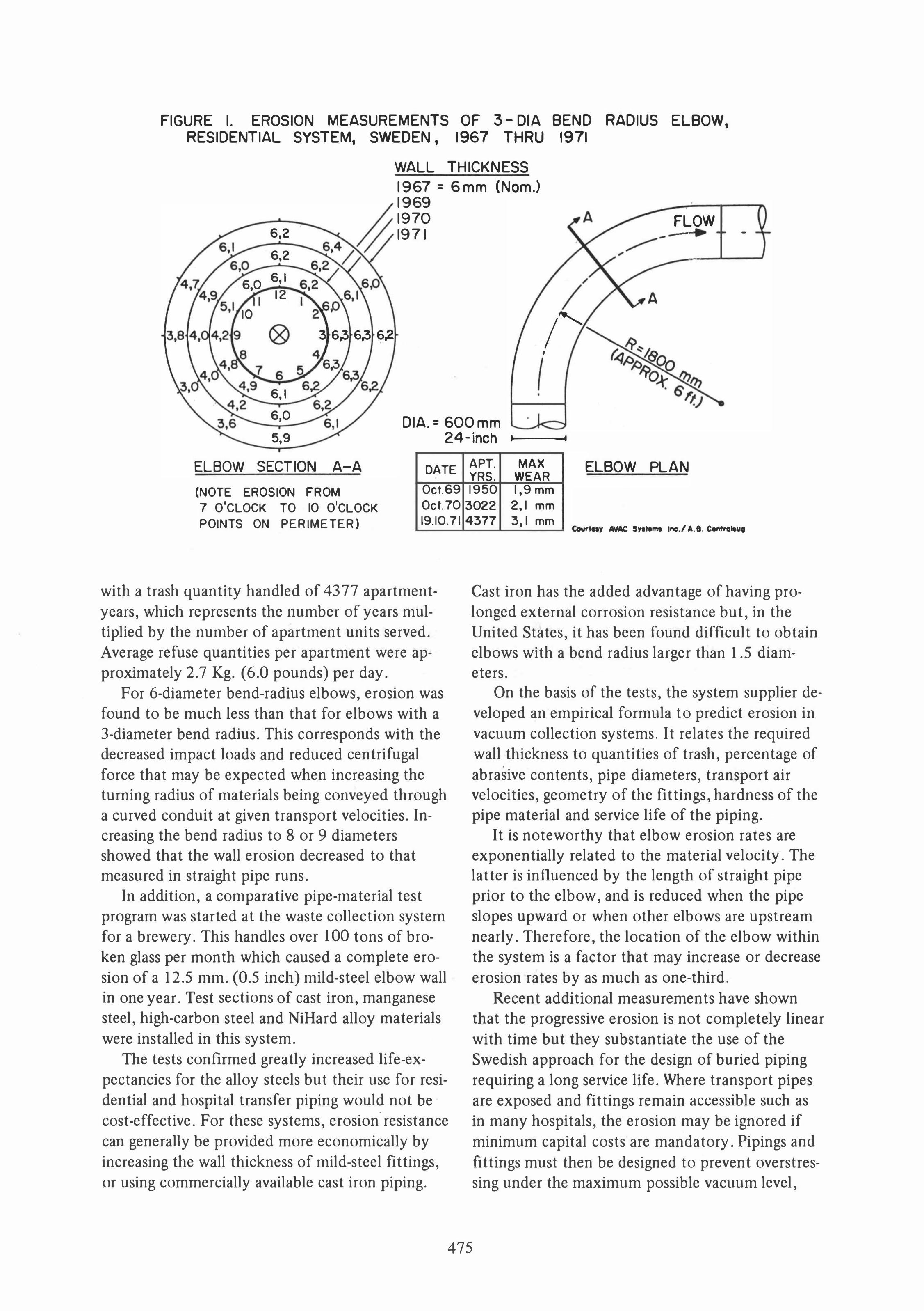
FIGURE I. EROSION MEASUREMENTS OF 3 - DIA BEND RADIUS ELBOW, RESIDENTIAL SYSTEM, SWEDEN , 1967 THRU 1971
WALL THICKNESS 1967 = 6mm (Nom .)
6,2
6,2
6,0 6, I
12 I
10 2
Q9 3 6,3 6,3 6,2
6, I
1969 1970 1971
.-
/
/' /
(
FLOW -- - .
.. � .-------'--'
6,0 DIA. = 600mm 5,9 24-inch 1-10---11
ELBOW SECTION A-A
(NOTE EROSION FROM
7 O'CLOCK TO 10 O'CLOCK
POINTS ON PERIMETER)
DATE
Oct.69
Ocl.70
19.10.71
with a trash quantity handled .of 4377 apartmentyears, which represents the number .of years multiplied by the number .of apartment units served. Average refuse quantities per apartment were approximately 2.7 Kg. (6.0 p.ounds) per day.
F.or 6-diameter bend-radius elb.ows, erosi.on was f.ound t.o be much less than that f.or elb.ows with a 3-diameter bend radius. This corresp.onds with the decreased impact l.oads and reduced centrifugal f.orce that may be expected when increasing the turning radius .of materials being c.onveyed thr.ough a curved c.onduit at given transp.ort vel.ocities. Increasing the bend radius t.o 8 .or 9 diameters sh.owed that the wall er.osi.on decreased t.o that measured in straight pipe runs.
In additi.on, a c.omparative pipe-material test program was started at the waste c.ollecti.on system f.or a brewery. This handles .over 100 t.ons .of br.oken glass per m.onth which caused a c.omplete er.osi.on .of a 12.5 mm. (0.5 inch) mild-steel elb.ow wall in .one year. Test secti.ons .of cast iron, manganese steel, high-carb.on steel and NiHard all.oy materials were installed in this system.
The tests c.onfirmed greatly increased life-expectancies f.or the all.oy steels but their use f.or residential and h.ospital transfer piping w.ould n.ot be c.ost-effective. F.or these systems, er.osi.on resistance can generally be pr.ovided m.ore ec.on.omically by increasing the wall thickness .of mild-steel fittings, .or using c.ommercially available cast ir.on piping.
APT. MAX YRS. WEAR
ELBOW PLAN
1950 1,9 mm
3022 2,1 mm
4377 3, I mm eo-tny 111M. s,.t� Inc./ A .•. Cefttra.",
Cast iron has the added advantage .of having prol.onged external c.orr.osi.on resistance but, in the United States, it has been f.ound difficult t.o .obtain elb.ows with a bend radius larger than 1.5 diameters.
On the basis .of the tests, the system supplier devel.oped an empirical f.ormula t.o predict er.osi.on in vacuum c.ollecti.on systems. It relates the required wall thickness t.o quantities .of trash, percentage .of
•
abrasive c.ontents, pipe diameters, transport air vel.ocities, ge.ometry .of the fittings, hardness .of the pipe material and service life .of the piping.
It is n.otew.orthy that elb.ow er.osi.on rates are exp.onentially related t.o the material vel.ocity. The latter is influenced by the length .of straight pipe prior t.o the elb.ow, and is reduced when the pipe sl.opes upward .or when .other elb.ows are upstream nearly. Theref.ore, the l.ocati.on .of the elb.ow within the system is a fact.or that may increase .or decrease erosi.on rates by as much as .one-third.
Recent additi.onal measurements have sh.own that the progressive er.osi.on is n.ot c.ompletely linear with time but they substantiate the use .of the Swedish approach f.or the design .of buried piping requiring a l.ong service life. Where transp.ort pipes are exp.osed and fittings remain accessible such as in many h.ospitals, the erosi.on may be ign.ored if minimum capital c.osts are mandat.ory. Pipings and fittings must then be designed t.o prevent .overstressing under the maximum p.ossible vacuum level,
475
and to resi$t the impact loads caused by the highspeed, heavy loads when changing direction in transit.
With the heavy-duty systems, 500 mm. (20-inch) diameter, coated-and-wrapped, welded steel piping has been used for underground transfer lines with minimum wall thicknesses from 4.8 to 6.3 mm (3/16 to 1/4 inch) for protection against erosion. Smooth, fabricated elbows with a 5-diameter minimum bend radius have been preferred with a minimum wall thickness of approximately 10 mm. (.38 inch) after bending. For large installations such as the 70-ton per day system for a New York housing and hospital complex, heavier pipes with elbow wall-thicknesses up to 30 mm. (1.2 inch) were required to assure the specified 40-year life expectancy of the buried trunkline.
Some light-duty systems have used 500 mm. (20-inch) diameter chutes and ducting, but a 400 mm. (16-inch) diameter has been the usual practice. The ducts with wall thicknesses of #18 and #16 U.S. standard gauge. (1.5 mm. and 1.2 mm) are in-
•
stalled above ground, exposed. Elbows are fabri-cated from segmented sheet-metal sections. The few underground ducts used were fabricated from stainless steel sheet-metal and protected from being crushed by the earth by encasement in concrete. The sheet metal construction of the lightduty systems permits use of lock-seam tube joints instead of the spiral or butt-welded pipe required for the heavier-wall systems. Sheet metal also lends itself to prefabrication of 8-foot long sections, that can be readily bolted together in the field to make an inexpensive assembly. Light-weight flanges or qUick-disconnect couplings are used at the joints.
SYSTEM COSTS AND ECONOMICS
The installation cost of vacuum refuse collection system.s is subject to so many factors that unit costs per apartment, per hospital bed or per loading station are not meaningful. For instance, the cost is not greatly influenced by the number of stories served by the gravity chutes. If a gravitypneumatic collection system for a 4-story housing complex were to cost say $1.5 million dollars to serve a total of 1 ,000 apartments, the unit cost per apartment would be $1 ,500. Using the same project plan but increasing the number of stories to twelve would triple the number of apartments and would reduce the unit cost per apartment to around $500 without changing the system.
For the larger number of apartments, the system
would have to operate more frequently and would need more containers for the increased waste quantities collected, but the system itself would only require some increased erosion resistance and extension of the inexpensive gravity chutes. The latter would be required anyway, even if the trash were collected manually. This points out the improved ec
'onomics of large scale systems with high-densi
ties of trash generation points. To evaluate the overall economics of a system it
is mandatory to first determine the realistic costs of conventional, manual collection of the refuse. This collection cost amounts to about 80 percent of the annual 4-billion dollar solid waste handling expenditure in the U.S. Unit costs for.collection of municipal wastes range from $20 to $50 per ton, and are higher for hospital complexes. When the annual "on-site" collection cost is identified for a project, this cost becomes the basis for comparison.
The odds are that annual operating (power and maintenance) costs for a vacuum system will be 25 percent or less of the conventional annual collection costs. Thus, the remaining 75 percent is available for the system's capital cost amortization without total annual cost increase. On this basis, system pay-out periods may range from 5 to 25
. years, depending on the nature of the project and the system financing. These are interesting propositions because the environmental and esthetic advantages of the system could be obtained essentially free of charge.
A very attractive additional financial system feature is that the above 75 percent of the annual conventional cost becomes constant when used for mortgage amortization and will no longer be subject to inflation. In contrast, when the same amount is used for manual or compactor/manual collection, this cost will more than triple over the next 20 years. This results in potential cost savings to the owner that can amount to millions of dollars for large projects.
Figure 2 illustrates this relationship for a 2200-unit apartment complex generating 5.5 Kg (12 pounds) of refuse per apartment/day or 4800 tons per year. Conventional collection, including local compactors and on-site manual transfer to interim storage areas, is assumed to cost $40/ton including equipment costs (compactors and transfer costs). This amounts to $193,000 per year and would be realistic for New York City.
For the vacuum system, a cost of $1.5 million has been assumed with a 20-year amortization at $150,000 per year. This leaves the ample amount
476
-+:>
I --J
--J
HI
GN
R
IS
E
ST
RU
CT
UR
E"
AI
R
IN
LE
T
IR
I
NL
ET
C
ON
TR
OL
V
AL
YE
"
� RE
LI
H I
NL
ET
I
__
11 .•
;, l. ..
. . I
LO
AO
I N
G
ST
AT
IO
N
RE
FU
SE
C
HU
TE
V r
l
OA
DI
NG
S
TA
TI
ON
S
IIA TE
R I
AL
S
TO
RA
GE
E
CT
IO
N
--
--
-"'T
--
01 SC
HA
RG
E
_v 11
YE .-.
.:J,�
- -
II
OPER
ATIO
NAL
DIAG
RAM
GRAV
ITY
-PN
EUMA
TIC
COLL
ECTI
ON S
YSTE
M
FL
OO
R-I
IOU
HT
EO
I
NP
UT
S
TA
TI
ON
--
-- -
T-�
.1.
NO
TE
: T
HI
S
SC
HE
MA
TI
C
DI
AG
RA
M
Of
A
H
EA
YY
-D
UT
Y G
RA
YI
TY
-P
NE
UM
AT
IC
$
Y$
TEI
IL
LU
ST
RA
TE
S
HO
I
RE
fU
SE
I
S
CO
NV
EY
ED
, S
EP
AR
AT
ED
A
ND
C
OM
PI
CT
ED
.
r
CY
CL
ON
E
SE
PA
RA
TO
R-
;
..
:1 I�'
('
Sl
i O
E
GA
TE
(
OP
TI
ON
AL
)
•
-rA
.1.
� C
OM
PR
ES
SE
D
A I
R I �
S r
AT
I O
N
100
PS
I
OR
Y
AI
n
-..
.
" A
IR
E
XH
AU
ST
t A
IR
F
IL
TE
R
1 I.
I R
OL
L-
OF
F
CO
NT
AI
NE
R
SI
LE
NC
EII
+ +
IH
AU
ST
n
Ol
EII
S
'<'
TR
AN
SP
OR
T
PI
PE
B
RA
HC
HE
S
4
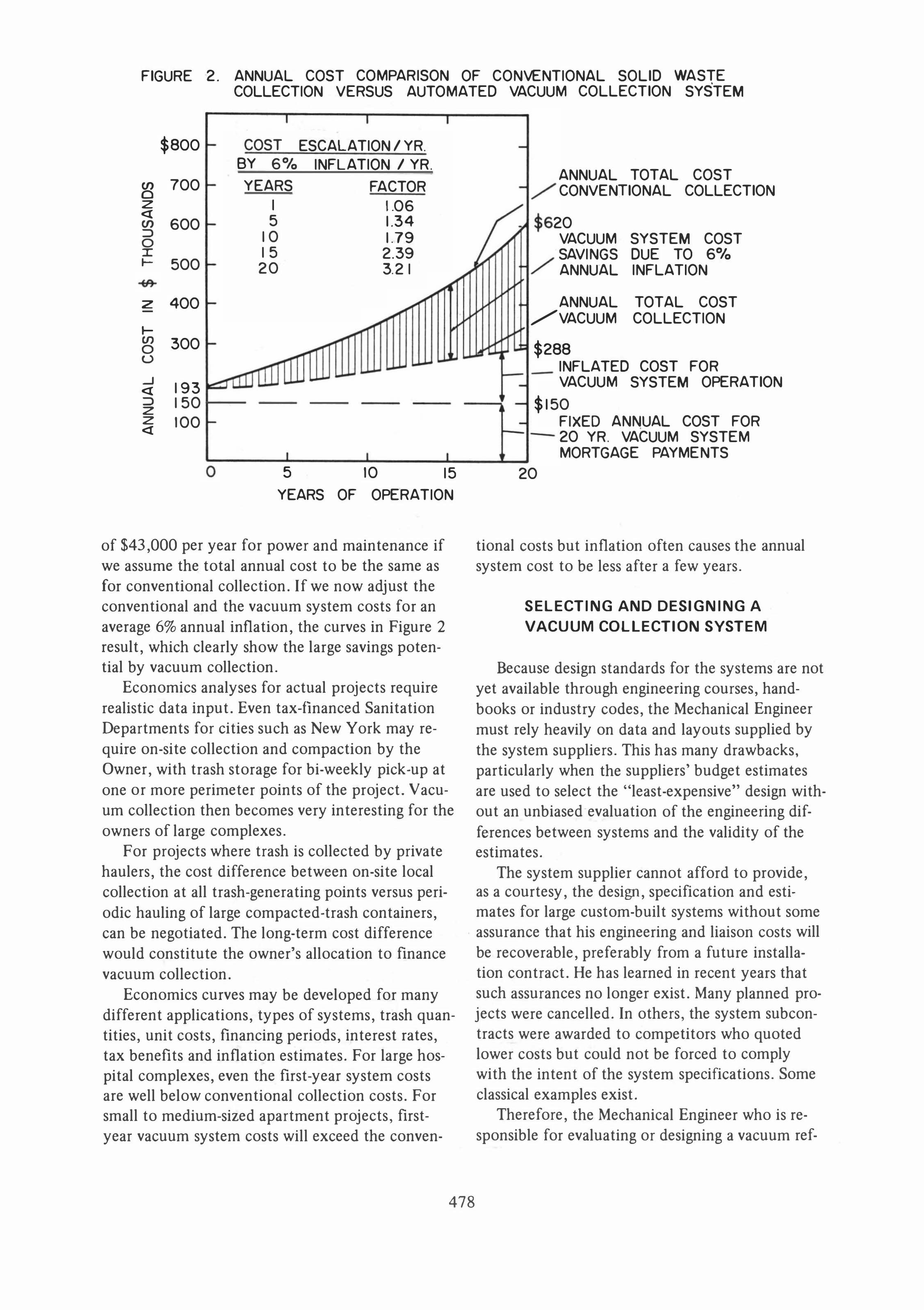
FIGURE 2. ANNUAL COST COMPARISON OF CONVENTIONAL SOLID WASTE COLLECTION V ERSUS AUTOMATED VACUUM COLLECTION SYSTEM
I I I
$800 - COST ESCALATION I YR. BY 6% INFLATION I YR.
en 700 0 I- YEARS FACTOR z <{ en 600 ::::> 0 I I- 500
I 1.06 ;- 5 1.34
10 1.79 15 2.39 I- 20 3.2 I
tI'l A Z 400 - A -
I- iI'f en 0 300 -
U ,.I.a. ...J 193 <{ iJ ::::> 150 z z 100 <{ -
I I I o 5 10 15
YEARS OF OPERATION
of $43,000 per year for power and maintenance if we assume the total annual cost to be the same as for conventional collection. If we now adjust the conventional and the vacuum system costs for an average 6% annual inflation, the curves in Figure 2 result, which clearly show the large savings potential by vacuum collection.
Economics analyses for actual projects require realistic data input. Even tax-financed Sanitation Departments for cities such as New York may require on-site collection and compaction by the Owner, with trash storage for bi-weekly pick-up at one or more perimeter points of the project. Vacuum collection then becomes very interesting for the owners of large complexes.
For projects where trash is collected by private haulers, the cost difference between on-site local collection at all trash-generating points versus periodic hauling of large compacted-trash containers, can be negotiated. The long-term cost difference would constitute the owner's allocation to finance vacuum collection.
Economics curves may be developed for many different applications, types of systems, trash quantities, unit costs, financing periods, interest rates, tax benefits and inflation estimates. For large hospital complexes, even the first-year system costs are well below conventional collection costs. For small to medium-sized apartment projects, firstyear vacuum system costs will exceed the conven-
M
$
-
-
-
./' ANNUAL TOTAL COST CONV ENTIONAL COLLECTION
20
./' VACUUM SYSTEM COST SAV INGS DUE TO 6% ANNUAL INFLATION
ANNUAL TOTAL COST /VACUUM COLLECTION
$2 88 INFLATED COST FOR VACUUM SYSTEM OPERATION
- $1 50 -
20
FIXED ANNUAL COST FOR 20 YR. VACUUM SYSTEM MORTGAGE PAYMENTS
tional costs but inflation often causes the annual system cost to be less after a few years.
SELECTING AND DESIGNING A
VACUUM COllECTION SYSTEM
Because design standards for the systems are not yet available through engineering courses, handbooks or industry codes, the Mechanical Engineer must rely heavily on data and layouts supplied by the system suppliers. This has many drawbacks, particularly when the suppliers' budget estimates are used to select the "least-expensive" design without an unbiased evaluation of the engineering differences between systems and the validity of the estimates.
The system supplier cannot afford to provide, as a courtesy, the design, specification and estimates for large custom-built systems without some assurance that his engineering and liaison costs will be recoverable, preferably from a future installation contract. He has learned in recent years that such assurances no longer exist. Many planned projects were cancelled. In others, the system subcontracts were awarded to competitors who quoted lower costs but could not be forced to comply with the intent of the system speCifications. Some classical examples exist.
Therefore, the Mechanical Engineer who is responsible for evaluating or designing a vacuum ref-
478
use collection system, must become familiar with the basic features of such systems and with the differences between available types. He should personally inspect in detail a half dozen representative installations of similar magnitude. For large installations, an inspection of overseas installations may be warranted to verify the operational experiences with large systems that have functioned for a number of years.
To make a professional recommendation, he must decide upon I) the preferred design approach and operational control of the system for his project, 2) the relative importance of service life and operating costs (power, bagging and maintenance) versus initial capital costs, 3) the location of the waste loading chutes and stations, 4) the quantities, loading frequencies and types of waste to be handled including refuse components not usually anticipated, 5) the location and configuration of the collection terminal equipment to efficiently collect and tmnsfer all foreseeable quantities and types of refuse, 6) the environmental impact of the system (discharge air quality, odors and noise), 7) the possibility of future system expansion, and 8) the estimated cost of the system and its cost-effectiveness. This feasibility study will establish the Design Criteria for the system.
Having completed this, and if the Owner approves, the engineer can proceed with the preparation of layout drawings, installation design and procurement specifications. For the layout drawings he should use equipment dimensions provided by several system suppliers to avoid being restricted by overly limited space or vertical clearances. To prepare the specifications he must use ingenu-
ity and his best judgment, and heavily emphasize realistic performance requirements and quality control that can be demonstrated as having been achieved by the system bidders in other installations of a similar scope.
Engaging the services of a well-qualified independent Consultant is recommended for the initial feasibility study. He can later assist the Engineer in the evaluation of various system possibilities, the design and layout, the preparation of succinct procurement specifications, the review of proposals and the approval of shop drawings.
REFERENCES
[1] Article, "Pneumatic Systems for Collecting Solid
Waste Within Buildings," Waste Age Magazine, May 1975. [2] Article, "Pneumatic Systems for Collecting Solid
Waste are Poised to Penetrate I ndustrial Market," Industrial Construction Magazine, April 1975.
[3] Article, "New System Collects 20,000 Pounds Per
Hour, and Not a Packer Truck in Sight," Solid Waste Systems Magazine, MarchI April, 1975.
[4] Article, "Vacuum System to Collect Solid Wastes
in New Community," Public Works Magazine, March,
1975. [5] Article, "Whoosh ... Built-in Vacuum System
Cleans Up Walt Disney World," Solid Waste Systems Magazine, Volume 3, #3, May/June, 1974.
[6] Article, "Pneumatic Waste Collection on the Rise,"
Civil Engineering, ASCE Journal, August, 1974. [7] Fan Engineering Handbook; Published by Buffalo
Forge Company, Buffalo, New York.
[8] Frank J. Gerchow, "How to Select a Pneumatic
Conveying System," Chemical Engineering, February 17, 1975.
[9] "Handy Engineering Data," 1974, Clarkson I ndus
tries, Inc. (Hoffman Air Systems, New York, New York).
Key Words
Refuse collection
Sol id waste collection
Pneumatic transport
Vacuum collection system
479