Embed Size (px)
Citation preview
Vacuum Pumps
PM2600
Use and maintenance manual
S
MORO USA, INC.
Email: [email protected] www.morousa.com
PITTSBURGH, PA OFFICE SALES OFFICE (800) 383-6304 (412) 787-8400
Fax: (412) 787-8444
ST. LOUIS, MO OFFICE Po Box 424
Union, MO 63084 (866) 383-6304
Fax: (636) 583-2044
2
ENGLISH
PRESENTATION
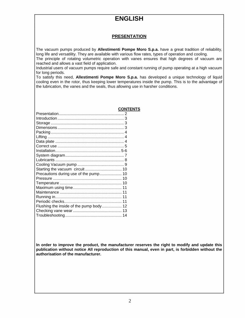
The vacuum pumps produced by Allestimenti Pompe Moro S.p.a. have a great tradition of reliability, long life and versatility. They are available with various flow rates, types of operation and cooling. The principle of rotating volumetric operation with vanes ensures that high degrees of vacuum are reached and allows a vast field of application. Industrial users of vacuum pumps require safe and constant running of pump operating at a high vacuum for long periods. To satisfy this need, Allestimenti Pompe Moro S.p.a. has developed a unique technology of liquid cooling even in the rotor, thus keeping lower temperatures inside the pump. This is to the advantage of the lubrication, the vanes and the seals, thus allowing use in harsher conditions.
CONTENTS Presentation ........................................................... 2 Introduction ............................................................ 3 Storage .................................................................. 3 Dimensions ............................................................ 3 Packing .................................................................. 4 Lifting ..................................................................... 4 Data plate .............................................................. 4 Correct use ............................................................ 5 Installation ........................................................... 5-6 System diagram ..................................................... 7 Lubricants .............................................................. 8 Cooling Vacuum pump .......................................... 9 Starting the vacuum circuit ................................. 10 Precautions during use of the pump .................... 10 Pressure .............................................................. 10 Temperature ........................................................ 10 Maximum using time ............................................ 11 Maintenance ........................................................ 11 Running in ............................................................ 11 Periodic checks.................................................... 11 Flushing the inside of the pump body .................. 12 Checking vane wear ............................................ 13 Troubleshooting ................................................... 14
In order to improve the product, the manufacturer reserves the right to modify and update this publication without notice All reproduction of this manual, even in part, is forbidden without the authorisation of the manufacturer.
3
INTRODUCTION For good operation of the vacuum pump, carefully read these instructions for use. This manual can help you solve all the problems that arise during assembly and use of the vacuum pump. We recommend that you always keep the manual in the vicinity of the vacuum pump. This manual is an integral part of the product.
KEEP THIS MANUAL WITH CARE FOR FUTURE CONSULTATION.
The user of the vacuum pump must be informed of the contents of this manual.
The manufacturer cannot be held responsible for any damage due to incorrect, erroneous or unreasonable use.
STORAGE To store the vacuum pump correctly, it must be stored as follows: - indoors, sheltered from external atmospheric agents; - in a horizontal position, standing on its four feet. During inspection, the vacuum pumps are lubricated in our factory with a particular oil which guarantees conservation of the various internal components for about 6 months. In the event of prolonged storage, we advise flushing the inside of the pump with Diesel fuel and oil (see page 11), checking and, if necessary, changing the gaskets.
PERFORMANCE
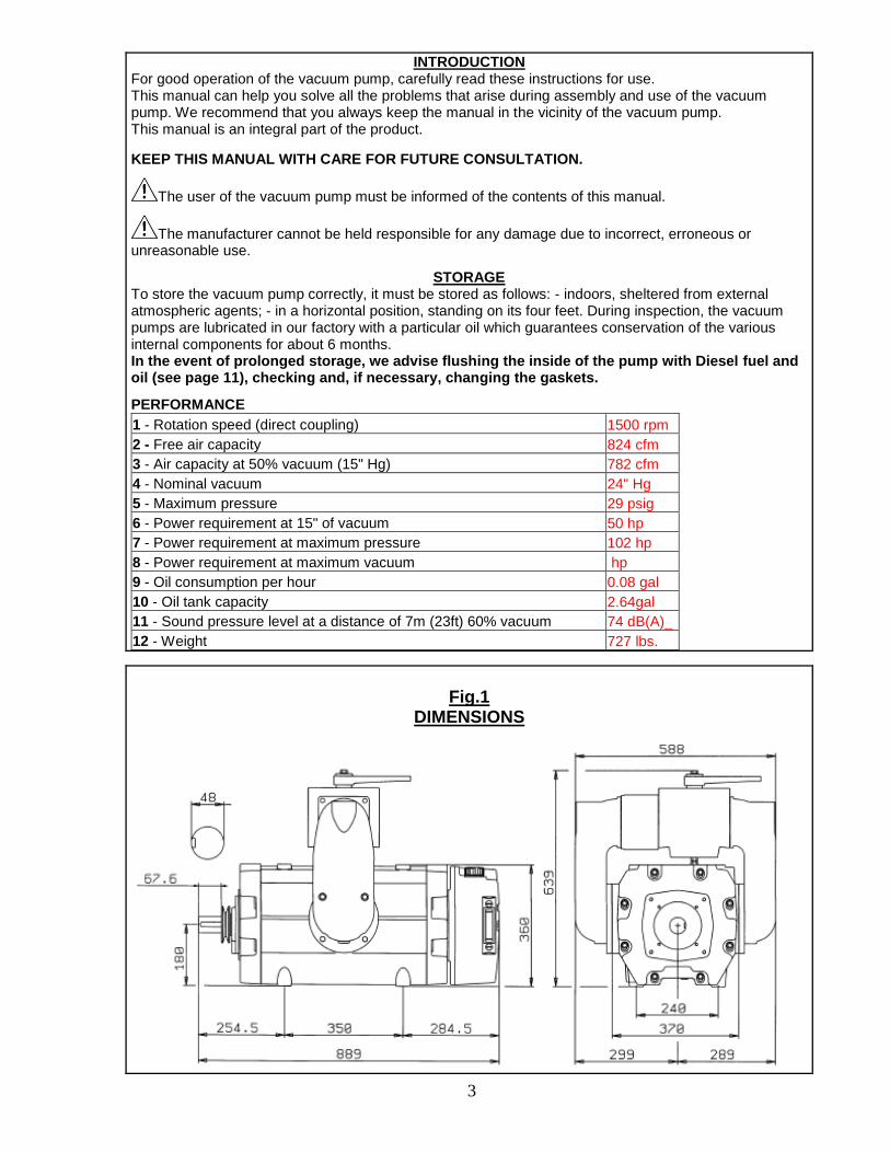
1 - Rotation speed (direct coupling) 1500 rpm
2 - Free air capacity 824 cfm
3 - Air capacity at 50% vacuum (15" Hg) 782 cfm
4 - Nominal vacuum 24" Hg
5 - Maximum pressure 29 psig
6 - Power requirement at 15" of vacuum 50 hp
7 - Power requirement at maximum pressure 102 hp
8 - Power requirement at maximum vacuum hp
9 - Oil consumption per hour 0.08 gal
10 - Oil tank capacity 2.64gal
11 - Sound pressure level at a distance of 7m (23ft) 60% vacuum 74 dB(A)_
12 - Weight 727 lbs.
Fig.1
DIMENSIONS
4
PACKING
The vacuum pump is supplied without packing. Special packing may be supplied on request, such as: - cardboard box; - wooden bed and shrink-wrap for single packages; - wooden pallet and shrink-wrap; - wooden crates and shrink-wrap. The packing components (bags, boxes, nails, etc.) must not be left within reach of children as they are potential sources of danger.
LIFTING
Lift the vacuum pump only by the eyebolts, see page 10. WEIGHT: See table on page 3.
ATTENTION: Do not damage the lines and oilers when lifting. GENERAL PRECAUTIONS
The warnings marked with this symbol indicate danger to personal safety.
The warnings marked with this symbol indicate danger to environmental safety.
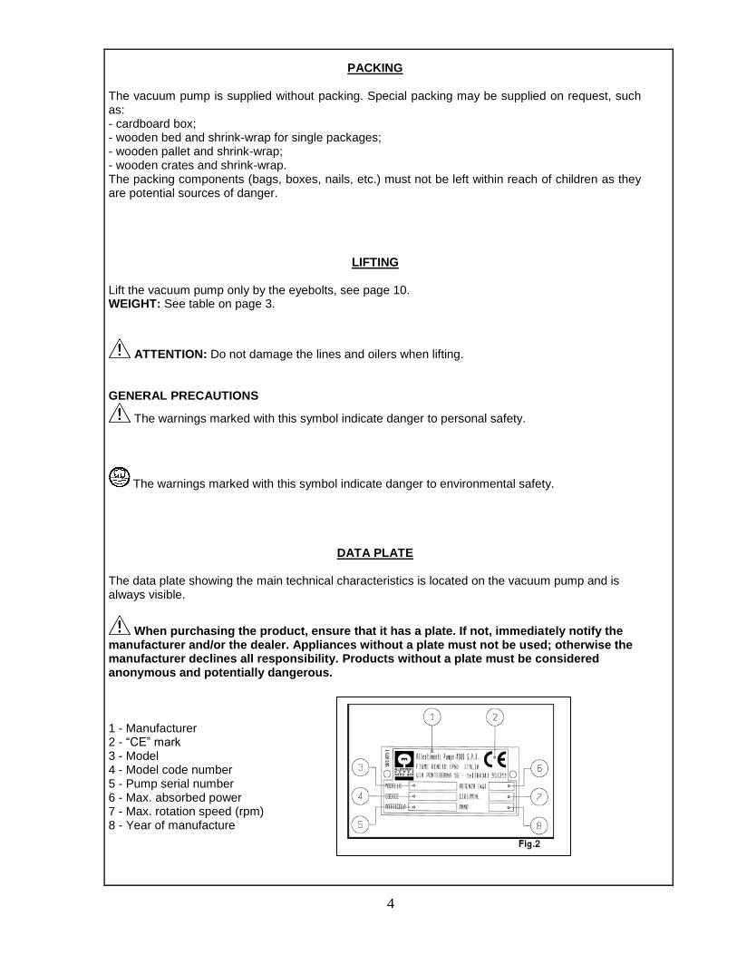
DATA PLATE
The data plate showing the main technical characteristics is located on the vacuum pump and is always visible.
When purchasing the product, ensure that it has a plate. If not, immediately notify the manufacturer and/or the dealer. Appliances without a plate must not be used; otherwise the manufacturer declines all responsibility. Products without a plate must be considered anonymous and potentially dangerous. 1 - Manufacturer 2 - “CE” mark 3 - Model 4 - Model code number 5 - Pump serial number 6 - Max. absorbed power 7 - Max. rotation speed (rpm) 8 - Year of manufacture
5
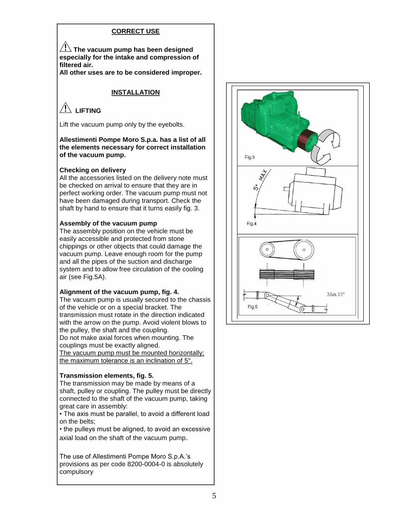
CORRECT USE
The vacuum pump has been designed especially for the intake and compression of filtered air. All other uses are to be considered improper.
INSTALLATION
LIFTING
Lift the vacuum pump only by the eyebolts. Allestimenti Pompe Moro S.p.a. has a list of all the elements necessary for correct installation of the vacuum pump. Checking on delivery All the accessories listed on the delivery note must be checked on arrival to ensure that they are in perfect working order. The vacuum pump must not have been damaged during transport. Check the shaft by hand to ensure that it turns easily fig. 3. Assembly of the vacuum pump The assembly position on the vehicle must be easily accessible and protected from stone chippings or other objects that could damage the vacuum pump. Leave enough room for the pump and all the pipes of the suction and discharge system and to allow free circulation of the cooling air (see Fig.5A). Alignment of the vacuum pump, fig. 4. The vacuum pump is usually secured to the chassis of the vehicle or on a special bracket. The transmission must rotate in the direction indicated with the arrow on the pump. Avoid violent blows to the pulley, the shaft and the coupling. Do not make axial forces when mounting. The couplings must be exactly aligned. The vacuum pump must be mounted horizontally; the maximum tolerance is an inclination of 5°. Transmission elements, fig. 5. The transmission may be made by means of a shaft, pulley or coupling. The pulley must be directly connected to the shaft of the vacuum pump, taking great care in assembly: • The axis must be parallel, to avoid a different load on the belts; • the pulleys must be aligned, to avoid an excessive
axial load on the shaft of the vacuum pump.
The use of Allestimenti Pompe Moro S.p.A.’s provisions as per code 8200-0004-0 is absolutely compulsory
6
The pump pulley cannot be used as a drive for other mechanisms.
Use only V-belts with profiles SPA, SPB, SPX.
For transmission with a shaft, do not exceed the max. shaft inclination of 15°. • The transmission parts must not be coupled by hammering them.
Suction pipes Avoid installing pipes subject to internal corrosion. When assembled, the pipe must be clean on the inside; accurately remove all welding slag, filings, rust or other foreign bodies.
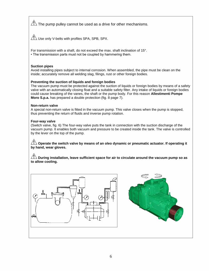
Preventing the suction of liquids and foreign bodies The vacuum pump must be protected against the suction of liquids or foreign bodies by means of a safety valve with an automatically closing float and a suitable safety filter. Any intake of liquids or foreign bodies could cause breaking of the vanes, the shaft or the pump body. For this reason Allestimenti Pompe Moro S.p.a. has prepared a double protection (fig. 8 page 7).
Non-return valve A special non-return valve is fitted in the vacuum pump. This valve closes when the pump is stopped, thus preventing the return of fluids and inverse pump rotation.
Four-way valve (Switch valve, fig. 6) The four-way valve puts the tank in connection with the suction discharge of the vacuum pump. It enables both vacuum and pressure to be created inside the tank. The valve is controlled by the lever on the top of the pump.
Operate the switch valve by means of an oleo dynamic or pneumatic actuator. If operating it by hand, wear gloves.
During installation, leave sufficient space for air to circulate around the vacuum pump so as to allow cooling.
7
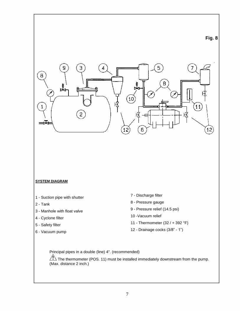
Fig. 8
SYSTEM DIAGRAM
1 - Suction pipe with shutter
2 - Tank
3 - Manhole with float valve
4 - Cyclone filter
5 - Safety filter
6 - Vacuum pump
7 - Discharge filter
8 - Pressure gauge
9 - Pressure relief (14.5 psi)
10 -Vacuum relief
11 - Thermometer (32 / + 392 °F)
12 - Drainage cocks (3/8” - 1”)
Principal pipes in a double (line) 4". (recommended)
The thermometer (POS. 11) must be installed immediately downstream from the pump. (Max. distance 2 inch.)
8
LUBRICANTS
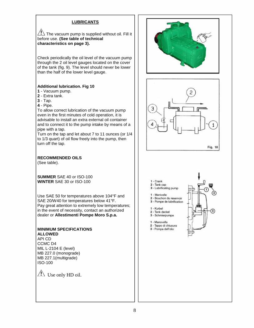
The vacuum pump is supplied without oil. Fill it before use. (See table of technical characteristics on page 3).
Check periodically the oil level of the vacuum pump through the 2 oil level gauges located on the cover of the tank (fig. 9). The level should never be lower than the half of the lower level gauge.
Additional lubrication. Fig 10 1 - Vacuum pump. 2 - Extra tank. 3 - Tap. 4 - Pipe. To allow correct lubrication of the vacuum pump even in the first minutes of cold operation, it is advisable to install an extra external oil container and to connect it to the pump intake by means of a pipe with a tap. Turn on the tap and let about 7 to 11 ounces (or 1/4 to 1/3 quart) of oil flow freely into the pump, then turn off the tap.
RECOMMENDED OILS (See table).
SUMMER SAE 40 or ISO-100 WINTER SAE 30 or ISO-100
Use SAE 50 for temperatures above 104°F and SAE 20/W40 for temperatures below 41°F. Pay great attention to extremely low temperatures; in the event of necessity, contact an authorized dealer or Allestimenti Pompe Moro S.p.a.
MINIMUM SPECIFICATIONS ALLOWED API CD CCMC D4 MIL L-2104 E (level) MB 227.0 (monograde) MB 227.1(multigrade) ISO-100
Use only HD oil.
9
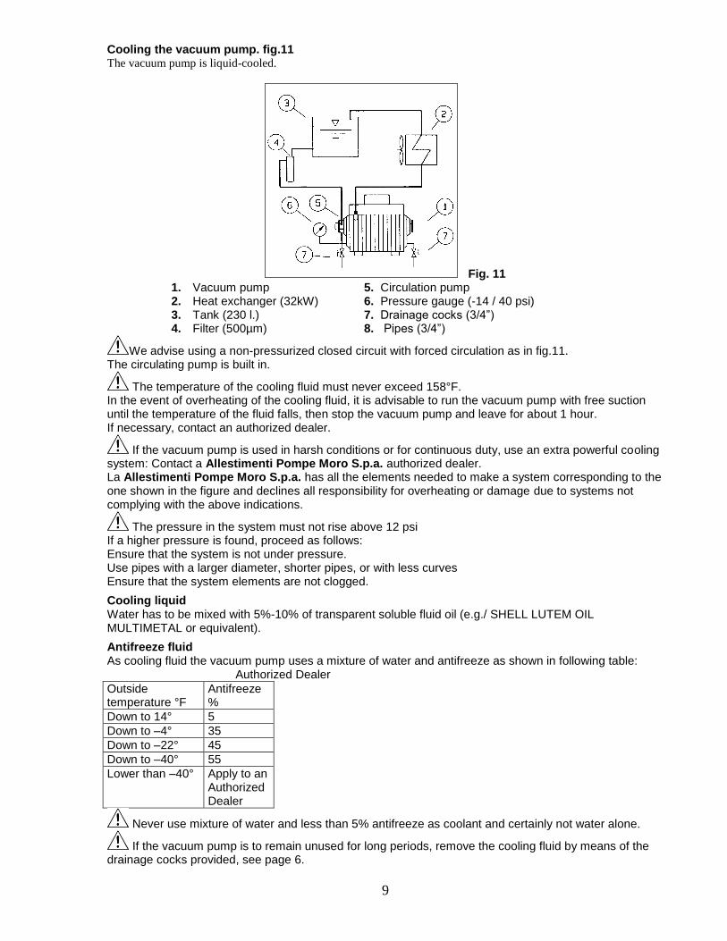
Cooling the vacuum pump. fig.11 The vacuum pump is liquid-cooled.
Fig. 11 1. Vacuum pump 5. Circulation pump 2. Heat exchanger (32kW) 6. Pressure gauge (-14 / 40 psi) 3. Tank (230 l.) 7. Drainage cocks (3/4”) 4. Filter (500µm) 8. Pipes (3/4”)
We advise using a non-pressurized closed circuit with forced circulation as in fig.11. The circulating pump is built in.
The temperature of the cooling fluid must never exceed 158°F. In the event of overheating of the cooling fluid, it is advisable to run the vacuum pump with free suction until the temperature of the fluid falls, then stop the vacuum pump and leave for about 1 hour. If necessary, contact an authorized dealer.
If the vacuum pump is used in harsh conditions or for continuous duty, use an extra powerful cooling system: Contact a Allestimenti Pompe Moro S.p.a. authorized dealer. La Allestimenti Pompe Moro S.p.a. has all the elements needed to make a system corresponding to the one shown in the figure and declines all responsibility for overheating or damage due to systems not complying with the above indications.
The pressure in the system must not rise above 12 psi If a higher pressure is found, proceed as follows: Ensure that the system is not under pressure. Use pipes with a larger diameter, shorter pipes, or with less curves Ensure that the system elements are not clogged.
Cooling liquid Water has to be mixed with 5%-10% of transparent soluble fluid oil (e.g./ SHELL LUTEM OIL MULTIMETAL or equivalent).
Antifreeze fluid As cooling fluid the vacuum pump uses a mixture of water and antifreeze as shown in following table: Authorized Dealer
Outside temperature °F
Antifreeze %
Down to 14° 5
Down to –4° 35
Down to –22° 45
Down to –40° 55
Lower than –40° Apply to an Authorized Dealer
Never use mixture of water and less than 5% antifreeze as coolant and certainly not water alone.
If the vacuum pump is to remain unused for long periods, remove the cooling fluid by means of the drainage cocks provided, see page 6.
10
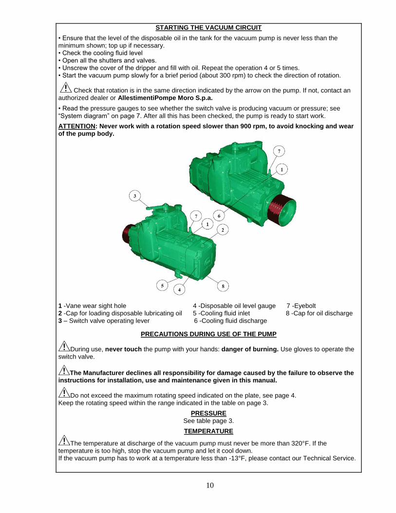
STARTING THE VACUUM CIRCUIT
• Ensure that the level of the disposable oil in the tank for the vacuum pump is never less than the minimum shown; top up if necessary. • Check the cooling fluid level • Open all the shutters and valves. • Unscrew the cover of the dripper and fill with oil. Repeat the operation 4 or 5 times. • Start the vacuum pump slowly for a brief period (about 300 rpm) to check the direction of rotation.
Check that rotation is in the same direction indicated by the arrow on the pump. If not, contact an authorized dealer or AllestimentiPompe Moro S.p.a.
• Read the pressure gauges to see whether the switch valve is producing vacuum or pressure; see “System diagram” on page 7. After all this has been checked, the pump is ready to start work.
ATTENTION: Never work with a rotation speed slower than 900 rpm, to avoid knocking and wear of the pump body.
1 -Vane wear sight hole 4 -Disposable oil level gauge 7 -Eyebolt 2 -Cap for loading disposable lubricating oil 5 -Cooling fluid inlet 8 -Cap for oil discharge 3 – Switch valve operating lever 6 -Cooling fluid discharge
PRECAUTIONS DURING USE OF THE PUMP
During use, never touch the pump with your hands: danger of burning. Use gloves to operate the switch valve.
The Manufacturer declines all responsibility for damage caused by the failure to observe the
instructions for installation, use and maintenance given in this manual.
Do not exceed the maximum rotating speed indicated on the plate, see page 4. Keep the rotating speed within the range indicated in the table on page 3.
PRESSURE See table page 3.
TEMPERATURE
The temperature at discharge of the vacuum pump must never be more than 320°F. If the temperature is too high, stop the vacuum pump and let it cool down. If the vacuum pump has to work at a temperature less than -13°F, please contact our Technical Service.
11
MAXIMUM USING TIME (MINUTES)
The maximum time of the pump employment in conditions of maximum vacuum depends on the type of application, from installation characteristics, and from pre-set cooling circuit. As a rule are valid the following prescriptions on cooling circuit in order to avoid excessive overheating. Without heat exchanger: max 40 minutes of continuous work with maximum vacuum. Heat exchanger with capacity till to 36,700 BTV/h: max 2 hours of continuous work with max vacuum. Heat exchanger with capacity till to 79,400 BTV/h: no limits at the continuous work with max vacuum. IMPORTANT The time indicated refers to normal working conditions with intermittent duty. For harsh conditions or for continuous duty, contact a Allestimenti Pompe Moro S.p.a. authorized dealer.
MAINTENANCE ONLY THE MAINTENANCE JOBS AUTHORIZED IN THIS INSTRUCTIONS MANUAL MAY BE CARRIED OUT BY THE USER. ALL OTHER OPERATIONS ARE FORBIDDEN.
RUNNING IN
The first 50 hours of actual operation of the pump are the run-in period. During this period, regularly check the consumption of oil, the discharge temperature and the wear of the vanes. Vane wear should be minimum or negligible. If it is excessive, wear must be checked at regular frequent intervals and the phenomenon should be notified to an authorized dealer. In any case, replace the vanes when wear is 10 mm or more (see page 13).
It is forbidden to use a pump with more than 10 mm vane wear. Failure to follow this warning relieves the manufacturer of all responsibility.
PERIODIC CHECKS
Periodic checks and maintenance of the machinery are recommended:
Several times a day: Check the dripping of oil from the oiler. Check the maximum temperature at discharge. Check the maximum temperature of the cooling fluid. Check the pressure in the cooling circuit.
Daily: Check the vacuum and the pressure during operation.
Daily: Check the level of the oil.
Weekly: Clean the filtering elements of all the filters.
Weekly: Clean the filtering elements of all the filters. Clean the heat exchanger in the cooling circuit Check the safety valve.
Monthly (or every 100 working hours): Check vane wear.
IMPORTANT: The times indicated refer to normal working conditions. For harsh conditions, decrease the intervals for each operation. Keep the pump clean in order to allow better cooling.
12
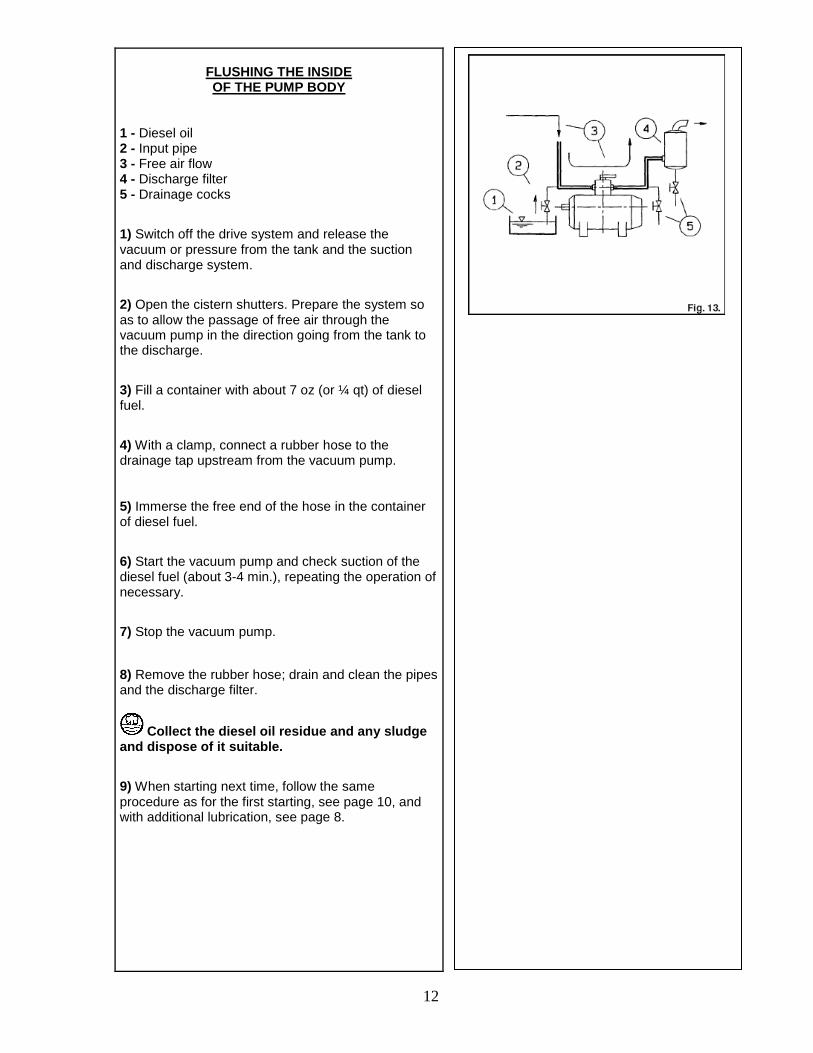
FLUSHING THE INSIDE OF THE PUMP BODY
1 - Diesel oil 2 - Input pipe 3 - Free air flow 4 - Discharge filter 5 - Drainage cocks
1) Switch off the drive system and release the vacuum or pressure from the tank and the suction and discharge system.
2) Open the cistern shutters. Prepare the system so as to allow the passage of free air through the vacuum pump in the direction going from the tank to the discharge.
3) Fill a container with about 7 oz (or ¼ qt) of diesel fuel.
4) With a clamp, connect a rubber hose to the drainage tap upstream from the vacuum pump. 5) Immerse the free end of the hose in the container of diesel fuel.
6) Start the vacuum pump and check suction of the diesel fuel (about 3-4 min.), repeating the operation of necessary.
7) Stop the vacuum pump.
8) Remove the rubber hose; drain and clean the pipes and the discharge filter.
Collect the diesel oil residue and any sludge and dispose of it suitable.
9) When starting next time, follow the same procedure as for the first starting, see page 10, and with additional lubrication, see page 8.
13
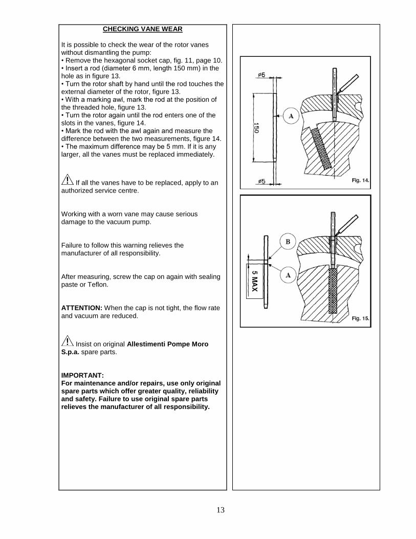
CHECKING VANE WEAR It is possible to check the wear of the rotor vanes without dismantling the pump: • Remove the hexagonal socket cap, fig. 11, page 10. • Insert a rod (diameter 6 mm, length 150 mm) in the hole as in figure 13. • Turn the rotor shaft by hand until the rod touches the external diameter of the rotor, figure 13. • With a marking awl, mark the rod at the position of the threaded hole, figure 13. • Turn the rotor again until the rod enters one of the slots in the vanes, figure 14. • Mark the rod with the awl again and measure the difference between the two measurements, figure 14. • The maximum difference may be 5 mm. If it is any larger, all the vanes must be replaced immediately.
If all the vanes have to be replaced, apply to an authorized service centre. Working with a worn vane may cause serious damage to the vacuum pump. Failure to follow this warning relieves the manufacturer of all responsibility. After measuring, screw the cap on again with sealing paste or Teflon. ATTENTION: When the cap is not tight, the flow rate and vacuum are reduced.
Insist on original Allestimenti Pompe Moro S.p.a. spare parts. IMPORTANT: For maintenance and/or repairs, use only original spare parts which offer greater quality, reliability and safety. Failure to use original spare parts relieves the manufacturer of all responsibility.
14
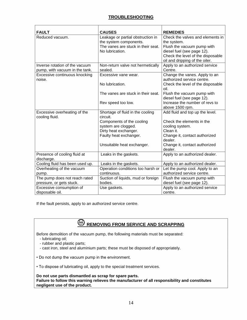
TROUBLESHOOTING
FAULT
CAUSES
REMEDIES
Reduced vacuum. Leakage or partial obstruction in the system components. The vanes are stuck in their seat. No lubrication.
Check the valves and elements in the system. Flush the vacuum pump with diesel fuel (see page 12). Check the level of the disposable oil and dripping of the oiler.
Inverse rotation of the vacuum pump, with vacuum in the tank.
Non-return valve not hermetically sealed.
Apply to an authorized service Centre.
Excessive continuous knocking noise.
Excessive vane wear. No lubrication. The vanes are stuck in their seat. Rev speed too low.
Change the vanes. Apply to an authorized service centre. Check the level of the disposable oil. Flush the vacuum pump with diesel fuel (see page 12). Increase the number of revs to above 1500 rpm.
Excessive overheating of the cooling fluid.
Shortage of fluid in the cooling circuit. Components of the cooling system are clogged. Dirty heat exchanger. Faulty heat exchanger. Unsuitable heat exchanger.
Add fluid and top up the level. Check the elements in the cooling system. Clean it. Change it, contact authorized dealer. Change it, contact authorized dealer.
Presence of cooling fluid at discharge.
Leaks in the gaskets. Apply to an authorized dealer.
Cooling fluid has been used up. Leaks in the gaskets. Apply to an authorized dealer.
Overheating of the vacuum pump.
Operation conditions too harsh or continuous.
Let the pump cool. Apply to an authorized service centre.
The pump does not reach rated pressure, or gets stuck.
Suction of liquids, mud or foreign bodies.
Flush the vacuum pump with diesel fuel (see page 12).
Excessive consumption of disposable oil.
Use gaskets. Apply to an authorized service centre.
If the fault persists, apply to an authorized service centre.
REMOVING FROM SERVICE AND SCRAPPING Before demolition of the vacuum pump, the following materials must be separated: - lubricating oil; - rubber and plastic parts; - cast iron, steel and aluminium parts; these must be disposed of appropriately. • Do not dump the vacuum pump in the environment. • To dispose of lubricating oil, apply to the special treatment services. Do not use parts dismantled as scrap for spare parts. Failure to follow this warning relieves the manufacturer of all responsibility and constitutes negligent use of the product.