Embed Size (px)
Citation preview
INSTALLATION AND OPERATION MANUAL
Vacuum Products Division
DRAFT 3/27/11Model RGC-150
Series Digital Vacuum
GaugeRGC-150 Ranges.001 to 760 Torr
.001 to 1013 millibar.001 to 101.3 kilopascal
Manual No. RGC150MRevision AMay 2010
Copyright 2010Agilent, Inc.
DRAFT 3/27/11
Agilent Model RGC-150 Series Digital Vacuum Gauge
iii
Model RGC-150 Series Digital Vacuum Gauge
Warranty
Products manufactured by Seller are warranted against defects in materials and workmanship for twelve (12) months from date of shipment thereof to Customer, and Seller’s liability under valid warranty claims is limited, at the option of Seller, to repair, to replace, or refund of an equitable portion of the pur-chase price of the Product. Items expendable in nor-mal use are not covered by this warranty. All warranty replacement or repair of parts shall be lim-ited to equipment malfunctions which, in the sole opinion of Seller, are due or traceable to defects in original materials or workmanship. All obligations of Seller under this warranty shall cease in the event of abuse, accident, alteration, misuse, or neglect of the equipment. In-warranty repaired or replaced parts are warranted only for the remaining unexpired por-tion of the original warranty period applicable to the repaired or replaced parts. After expiration of the applicable warranty period, Customer shall be charged at the then current prices for parts, labor, and transportation.
Reasonable care must be used to avoid hazards. Seller expressly disclaims responsibility for loss or damage caused by use of its Products other than in accordance with proper operating procedures.
Except as stated herein, Seller makes no warranty, express or implied (either in fact or by operation of law), statutory or otherwise; and, except as stated herein, Seller shall have no liability under any war-ranty, express or implied (either in fact or by opera-tion of law), statutory or otherwise. Statements made by any person, including representatives of Seller, which are inconsistent or in conflict with the terms of this warranty shall not be binding upon Seller unless reduced to writing and approved by an officer of Seller.
Warranty Replacement and Adjustment
All claims under warranty must be made promptly after occurrence of circumstances giving rise thereto, and must be received within the applicable warranty period by Seller or its authorized represen-tative. Such claims should include the Product serial number, the date of shipment, and a full description of the circumstances giving rise to the claim. Before any Products are returned for repair and/or adjust-ment, written authorization from Seller or its autho-rized representative for the return and instructions as to how and where these Products should be returned must be obtained. Any Product returned to Seller for examination shall be prepaid via the means of trans-portation indicated as acceptable by Seller. Seller reserves the right to reject any warranty claim not promptly reported and any warranty claim on any item that has been altered or has been returned by non-acceptable means of transportation. When any Product is returned for examination and inspection, or for any other reason, Customer shall be responsi-ble for all damage resulting from improper packing or handling, and for loss in transit, notwithstanding any defect or non-conformity in the Product. In all cases, Seller has the sole responsibility for determin-ing the cause and nature of failure, and Seller’s determination with regard thereto shall be final.
If it is found that Seller’s Product has been returned without cause and is still serviceable, Customer will be notified and the Product returned at Customer’s expense; in addition, a charge for testing and exam-ination may be made on Products so returned.
3/1/00

Model RGC-150 Series Digital Vacuum Gauge
This page intentionally left blank.
Model RGC-150 Series Digital Vacuum Gauge
DR
AF
T 3
/27
/11
v
Contents
Description and Principle Of Operation........................................................................................ 1 Construction................................................................................................................................. 1 Unpacking and Inspection............................................................................................................ 2Installation..................................................................................................................................... 2Operation ...................................................................................................................................... 5Servicing and Maintenance........................................................................................................... 6
Gauge Tube Servicing ............................................................................................................ 6Maintenance............................................................................................................................ 6Factory Repair and Calibration ............................................................................................... 6Field Calibration ...................................................................................................................... 7
Notes on Calibration ..................................................................................................................... 7Understanding Torr ....................................................................................................................... 8Accessories and Modifications...................................................................................................... 8
Special Requirements ............................................................................................................. 8Specifications................................................................................................................................ 9

Model RGC-150 Series Digital Vacuum Gauge
This page intentionally left blank.
DR
AF
T 3
/27
/11
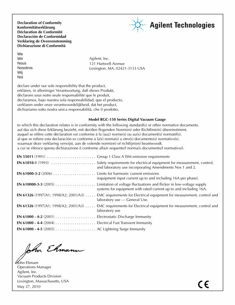
John EhmamOperations Manager
Vacuum Products DivisionAgilent, Inc.
Agilent, Inc.
declare under our sole responsibility that the product,erklären, in alleniniger Verantwortung, daß dieses Produkt,déclarons sous notre seule responsabilité que le produit,declaramos, bajo nuestra sola responsabilidad, que el producto,verklaren onder onze verantwoordelijkheid, dat het product,dichiariamo sotto nostra unica responsabilità, che il prodotto,
Declaration of ConformityKonformitätserklärungDéclaration de ConformitéDeclaración de ConformidadVerklaring de OvereenstemmingDichiarazione di Conformità
to which this declaration relates is in conformity with the following standard(s) or other normative documents.auf das sich diese Erklärung bezieht, mit der/den flogenden Norm(en) oder Richtlinie(n) übereinstimmt.auquel se réfère cette déclaration est conforme à la (auz) norme(s) ou au(x) document(s) normatif(s).al que se refiere esta declaración es conforme a la(s) norma(s) u otro(s) documento(s) normativo(s).waamaar deze verklaring verwijst, aan de volende norm(en) of richtlijn(en) beantwoodt.a cui se rifersce questa dichiarazione è conforme alla/e sequente/I norma/o documento/I normativo/i.
WeWirNousNosotrosWijNoi
Lexington, MA, 02421-3133 USA 121 Hartwell Avenue
Lexington, Massachusetts, USA
Model RGC-150 Series Digital Vacuum Gauge
EN 55011 (1991) . . . . . . . . . . . . . . . . . . . . . . . Group 1 Class A ISM emission requirements
EN 61010-1 (1993) . . . . . . . . . . . . . . . . . . . . . Safety requirements for electrical equipment for measurement, control, and laboratory use incorporating Amendments Nos 1 and 2.
EN 61000-3-2 (2006) . . . . . . . . . . . . . . . . . . . . Limits for harmonic current emissions(equipment input current up to and including 16A per phase).
EN 610000-3-3 (2005) . . . . . . . . . . . . . . . . . . . Limitation of voltage fluctuations and flicker in low-voltage supply systems for equipment with rated current up to and including 16A.
EN 61326 (1997/A1; 1998/A2; 2001/A3) . . . . . EMC requirements for Electrical equipment for measurement, control and laboratory use — General Use.
EN 61326 (1997/A1; 1998/A2; 2001/A3) . . . . . EMC requirements for Electrical equipment for measurement, control and laboratory use
EN 61000 - 4-2 (2001) . . . . . . . . . . . . . . . . . . . Electrostatic Discharge Immunity
EN 61000 - 4-4 (2004) . . . . . . . . . . . . . . . . . . . Electrical Fast Transient Immunity
EN 61000 - 4-5 (2005) . . . . . . . . . . . . . . . . . . . AC Lightning Surge Immunity
May 27, 2010
Model RGC-150 Series Digital Vacuum Gauge
DR
AF
T 3
/27
/11
viii
Preface
Hazard and Safety Information
This manual uses the following standard safety protocols:
WARNING The warning messages are for attracting the attention of the operator to a particular procedure or practice which, if not followed correctly, could lead to serious injury.
CAUTION The caution messages are displayed before procedures, which if not followed, could cause damage to the equipment.
NOTE The notes contain important information.
This product must only be operated and maintained by trained personnel. Board installation/replacement requires a properly trained service technician.
Before operating or servicing equipment, read and thoroughly understand all operation/maintenance manuals provided by Agilent. Be aware of the hazards associated with this equipment, know how to recognize potentially hazardous conditions, and how to avoid them. Read carefully and strictly observe all cautions and warnings. The consequences of unskilled, improper, or careless operation of the equipment can be serious.
In addition, consult local, state, and national agencies regarding specific requirements and regulations. Address any safety, operation, and/or maintenance questions to your nearest Agilent office.
1
Model RGC-150 Series Digital Vacuum Gauge
DR
AF
T 3
/27
/11
Description and Principle Of Operation
The Agilent RGC-150 series gauge is a compact digital vacuum sensing instrument. It uses a thermocouple gauge tube to sense vacuum and display the reading in either milliTorr, mbar or kilopascal. The Agilent Model RGC-150 can either be panel mounted or sit on a bench top, and comes standard with 2 SPDT controls, analog output and RS232 data. The Agilent Model RGC-150 is designed to be used with the Agilent 531 thermocouple gauge tubes. If in doubt about what gauge sensor you have, consult the Agilent packing list that came with your instrument for positive identification.
Consult the Agilent website www.Agilentinc.com for information about other Agilent vacuum instruments and controllers.
The Agilent Model RGC-150 operates by measuring the temperature rise of an electrically heated thermocouple exposed to a vacuum. As vacuum increases, or more correctly, as absolute pressure decreases, fewer and fewer molecules of gas are available to cool the thermocouple. With fewer molecules in the vacuum space, the air temperature rises and the thermocouple gauge thus senses the vacuum. A precision reference inside the Agilent in conjunction with an integrated circuit amplifier controls the electrical excitation of the sensor filament. The voltage response of the thermocouple is piped through a CPU and is translated to the current vacuum reading.
Construction
The RGC-150 consists of the indicating and controlling instrument, the gauge tube, the gauge tube cable, interfaces for the 2 control connections, analog out, RS232 and an AC power adapter.
The instrument is housed in a rugged free-standing plastic enclosure. It can either be placed on a suitable surface, or can be mounted in a 1/8 DIN panel cutout. The gauge tube houses the various thermocouple sensing, heating and compensating elements and terminates in an octal connector. On this model, the connector wiring terminates at the instrument with a 6 position RJ24. Regulating circuitry in the Agilent provides proper current for gauge tube excitation, and thus compensates for resistance in the probe leads.
Model RGC-150 Series Digital Vacuum Gauge
2
DR
AF
T 3
/27
/11
Unpacking and Inspection
After the Agilent RGC-150 is received, carefully unpack and inspect it for damage during shipment and for completeness. In the event of a loss during shipment, immediately make a claim to the common carrier or the postal service, as applicable. The Agilent warranty pertains only to the instrument, and does not cover losses in shipping.
Each RGC-150 comes with:
❑ Display controller (black box with front panel buttons)
❑ Universal Plug - Power supply
❑ Gauge Tube Cable
❑ Agilent 531 gauge tube
❑ Mounting Brackets and four (4) rubber feet
❑ Quick Start Guide
❑ Ferrite for gauge tube cable
Installation
Locate the instrument in a clean, dry environment for best results. The unit can be panel mounted with the hardware provided in a 1/8” DIN panel cutout (3.64" x 1.78" [92mm x 45 mm]). Alternatively, the unit can be placed on a desktop by placing the 4 rubber feet included with your gauge on the underside of the unit. Identify the gauge tube cable by wire tags or markings specific to your environment.
Thermocouple gauge tubes must be installed in a thread-down orientation in a clean, dry vacuum system. While threading the gauge tube in to the manifold, disconnect the gauge tube cable to avoid damage. In this way, twisting of the cable and the octal socket on the tube is avoided. Exercise care to install the tubes in a dry part of the system. Since the instrument works on the principle of temperature rise, the probes will not work if they become filled with a liquid such as vacuum or diffusion pump oil. Protect the gauge tube against oil and other contaminants by installing it in such a way to protect it. A good practice is to mount the gauge tube in the most vertically distant place from oil and other contaminants as applicable. Mount the gauge tube in the most stable pressure region of the vessel to be measured. For example, install the gauge tube on a tank rather than on the pipe that is directly connected to a vacuum pump. In the event of contamination, see “Servicing and Maintenance” on page 6 for gauge tube cleaning instructions.
Model RGC-150 Series Digital Vacuum Gauge
DR
AF
T 3
/27
/11
3
If the gauge is used in a Neon sign processing facility, the following is recommended to protect the gauge from bombarding damage:
❑ Isolate the gauge tube from the system with a stopcock. Close the stopcock when bombarding.
❑ There must be at least two (2) feet of tubing between the electrode and the Instrument. For best results, use metal the tubing.
❑ In extreme cases, the gauge can be absolutely protected by installing a normally open solenoid valve between the gauge tube and the system. Place the solenoid valve coil in parallel with the bombarding transformer. In this way, the solenoid is closed and the gauge tube is positively protected whenever bombarding.
❑ If a gauge is damaged by bombarding, it can generally be brought back to operating condition by replacing the Op amp which controls the gauge tube current. Consult Agilent.
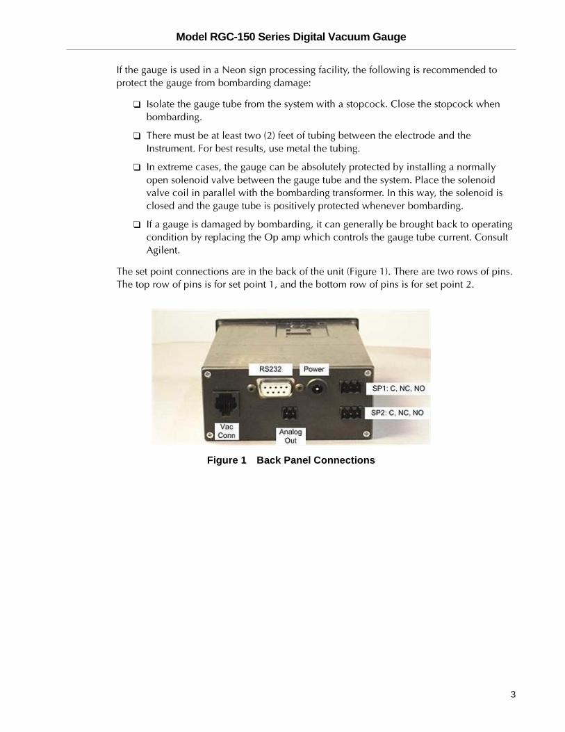
The set point connections are in the back of the unit (Figure 1). There are two rows of pins. The top row of pins is for set point 1, and the bottom row of pins is for set point 2.
Figure 1 Back Panel Connections
Model RGC-150 Series Digital Vacuum Gauge
4
DR
AF
T 3
/27
/11
The top 3 pins are in the order:
Common The common line of a switch.
N.C. Normally closed. This means that above the set point value there is a current path between the common and the N.C. terminal. Put another way the switch is ON between these 2 terminals. At the set point value and below (higher vacuum, lower pressure) the con-nection is open. Put another way, the switch is OFF between the common and the N.C. connection at higher vacuum (a lower pres-sure reading).
N.O. Normally open. This means that above the set point value there is no current path between the common and N.O. connection. Put another way the switch is OFF between these 2 terminals. When the vacuum indication goes below the set point value (higher vac-uum, lower pressure) the current path closes. Put another way the switch is ON between the common and N.O. connections at abso-lute pressure readings below the set point value.
Ensure that the wire connections are made fast, and the voltage and current does not exceed 250V or 7A. If you need to control a device that draws more power, consider another relay in between the Agilent output and the device to be controlled
The Analog output is located in the center of the back panel, and must be connected to a high impedance input. The output impedance is 1KÙ.
The RS232 connection can be made to a PLC or computer via a male DB9 cable connection to the female DB9 connection on the Agilent. The Agilent acts as a DCE, so a straight serial connection is appropriate.
Use the supplied 5V AC adapter with your Instrument. This adapter provides clean short protected power to protect and insure proper functioning of the internal circuitry.
Model RGC-150 Series Digital Vacuum Gauge
DR
AF
T 3
/27
/11
5
Operation
After installation, the Agilent AGC-150 is ready for immediate operation. The unit normally provides accurate readings immediately, however occasionally a gauge tube may have absorbed material during storage, and may require as much as 24 hours of operation before accurate readings are attained. It is recommended that the AGC-150 be energized continuously during vacuum system operation. In this way, the hot filament does not allow contaminants to condense.
In cases where the system has contaminants, as is often the case with metalizing and coating equipment, it is often effective to isolate the gauge tube with a solenoid or manual valve during periods when contamination is most active.
The Agilent controller can be easily set to the desired units on the fly:
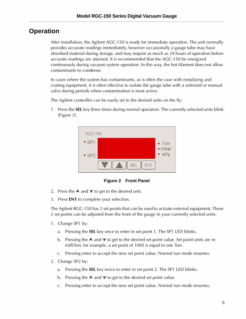
1. Press the SEL key three times during normal operation. The currently selected units blink (Figure 2).
Figure 2 Front Panel
2. Press the ���� and ���� to get to the desired unit.
3. Press ENT to complete your selection.
The Agilent RGC-150 has 2 set points that can be used to actuate external equipment. These 2 set points can be adjusted from the front of the gauge in your currently selected units.
1. Change SP1 by:
a. Pressing the SEL key once to enter in set point 1. The SP1 LED blinks.
b. Pressing the ���� and ���� to get to the desired set point value. Set point units are in milliTorr, for example, a set point of 1000 is equal to one Torr.
c. Pressing enter to accept the new set point value. Normal run mode resumes.
2. Change SP2 by:
a. Pressing the SEL key twice to enter in set point 2. The SP1 LED blinks.
b. Pressing the ���� and ���� to get to the desired set point value.
c. Pressing enter to accept the new set point value. Normal run mode resumes.
Model RGC-150 Series Digital Vacuum Gauge
6
DR
AF
T 3
/27
/11
NOTE If you don’t want the set points to actuate or the LEDs to illuminate at all, set the set point for 000.
One of the units LEDs, to the right of the display, is always lit during normal operation to
indicate which pressure range the display is indicating.
The Instrument has additional outputs which can be used:
❑ RS232 – The instrument puts out a standard RS232 serial stream with settings 9600,
8, N, and 1. The unit transmits but does not receive, and displays the current vacuum indication in the current units.
❑ Analog out – This output reads from 0 to 5 Volts from a pressure of 1 micron all the
way up to 5 Torr. There is a graduation of 1 milliVolt per milliTorr. Therefore, 10 milliVolts = 10 milliTorr, and 4 Volts = 4 Torr.
Servicing and Maintenance
Gauge Tube Servicing
In many cases, a gauge tube may become fouled with oil or other foreign matter. It is often possible to restore the functionality of contaminated probes with cleaning. If the
contaminant is known, fill the tube with a fluid that is known to be a solvent to that
contaminant. As an example, ether is often effective in removing residues of some oils. Commercial carburetor cleaners are very powerful solvents and are highly effective against
some contaminants.
After cleaning with solvents, completely dry or flush the gauge tube with a volatile solvent to assure that it is dry prior to re-installing it. If this is not done, contamination of the system
may result.
Maintenance
Your vacuum instrument should give you many years of trouble free service. There are no
regularly scheduled maintenance intervals. If consistent accuracy is required, it is recommended that the gauge, tube, cable and power supply be returned for a yearly
calibration check.
Factory Repair and Calibration
The vacuum gauge assembly is designed to provide years of trouble-free service, and the
liberal internal use of plug-in components make it easily repairable. No field servicing of the unit is recommended, other than replacement of the gauge tube, but factory servicing and
calibration are available at a nominal cost and fast turn-around times.
Model RGC-150 Series Digital Vacuum Gauge
DR
AF
T 3
/27
/11
7
Field Calibration
Each Agilent vacuum gauge controller is calibrated to the particular vacuum gauge sensor that is shipped with the unit. While changing the gauge tube is possible, it results in a slightly different reading as all gauge tubes are not created equal. Although it is preferable that all calibration be performed at Agilent, field calibration can be accomplished.
Before re-calibrating the instrument, ascertain if the instrument is in fact incorrect. In many cases, the problem is with a fouled tube, or a system that is operating improperly. It is recommended that a spare tube be kept on hand and stored in a clean, dry place. Then, in cases of suspect readings, change the tube before proceeding further.
If adjustments are to be made, proceed as follows:
1. Remove the Instrument from the panel.
2. Remove the unit from the plastic case and locate the two calibration potentiometers.
3. Operate the vacuum system at the lowest attainable pressure, and allow the system and the gauge tube to stabilize for several minutes. Factory zero setting is done at a pressure of .1 milliTorr (.1 micron) or less.
4. Adjust the zero setting potentiometer so the unit reads zero. Make sure not to under span. Allow the measurement standard to rise to 1 milliTorr and make sure the gauge reading also reads 1 milliTorr.
5. Check the operation of the gauge at other pressures. Normally, slight adjustments of the zero will not be interactive with the readings of the instrument at higher pressures.
The ATM adjustment is normally not necessary, if necessary:
1. Adjust the span with the ATM potentiometer.
2. Set the vacuum level to Atmosphere (approximately 760 Torr) for the RGC-150, and slowly turn the potentiometer on the right until the RGC-150 reads 760 Torr, being careful not to over span.
3. If you adjust the span, recheck the zero, then the span, and the zero one last time.
Notes on Calibration
The instrument is calibrated in nitrogen, which has thermal properties virtually identical to air. Other gasses affect the readings by an amount proportional to the thermal conductivity of the gases. In most cases, the gases present in a vacuum system are air, nitrogen, or oxygen, and no appreciable errors occur.
Certain other gases, however, have thermal conductivity significantly greater than air and cause the instrument to read higher than the actual amount of pressure. Examples of such gasses are water vapor, fluorocarbon refrigerants, and acetone. Conversely, other gasses have thermal conductivity significantly lower than air and cause the instrument to read lower than actual pressure. Examples of such gasses include helium, oxygen and to a lesser extent, CO2.
Model RGC-150 Series Digital Vacuum Gauge
8
DR
AF
T 3
/27
/11
When interpreting readings using gasses other than air, remember that the Agilent AGC-150 reads Torr, which is a measure of absolute pressure - that is the opposite of vacuum. Thus, a lower numerical reading actually is a higher level of vacuum. For more information, refer to “Understanding Torr” on page 8. When in doubt, consult Agilent.
Understanding Torr
The Agilent AGC-150 and many similar instruments are calibrated in microns or milliTorr. It is appropriate to discuss what microns are and to relate microns to other measures of pressure and vacuum. Microns are not really a measure of vacuum at all, but rather of absolute pressure. The pressure of the atmosphere is 14.696 or approximately 14.7 pounds per square inch at sea level. This pressure is due to the weight of all of the air in the earth's atmosphere above any particular square inch. This 14.696 psi is equivalent to the pressure produced by a mercury column of approximately 29.92 inches high or .76 meters (about 3/4 of a yard) or 760 millimeters of mercury. Atmospheric pressure varies greatly with altitude. It decreases approximately 1 inch of mercury per thousand feet of altitude. It also varies widely with local weather conditions. (Variations of one half inch in a single day are common.) The word vacuum means pressure lower than atmospheric or suction, but, in describing negative pressure, the atmosphere is only a satisfactory reference if we are dealing with values of vacuum down to about 27 inches of mercury. Below that, it is much more useful to talk in terms of absolute pressure, starting from absolute zero. The RGC-150 and all similar instruments do just this.
One TORR, a commonly used unit, is an absolute pressure of one millimeter of mercury. A milliTorr is equal to one thousandth of a TORR. A MICRON is the same as a milliTorr.
Accessories and Modifications
Consult the product guide and website for the latest available accessories. We also offer this gauge with Ethernet capability that allows the user to log vacuum data to a web browser.
Special Requirements
It is the policy of the Agilent Company to customize instruments for specialized requirements whenever it is economically feasible to do so. We encourage inquiries about your special needs.
Model RGC-150 Series Digital Vacuum Gauge
DR
AF
T 3
/27
/11
9
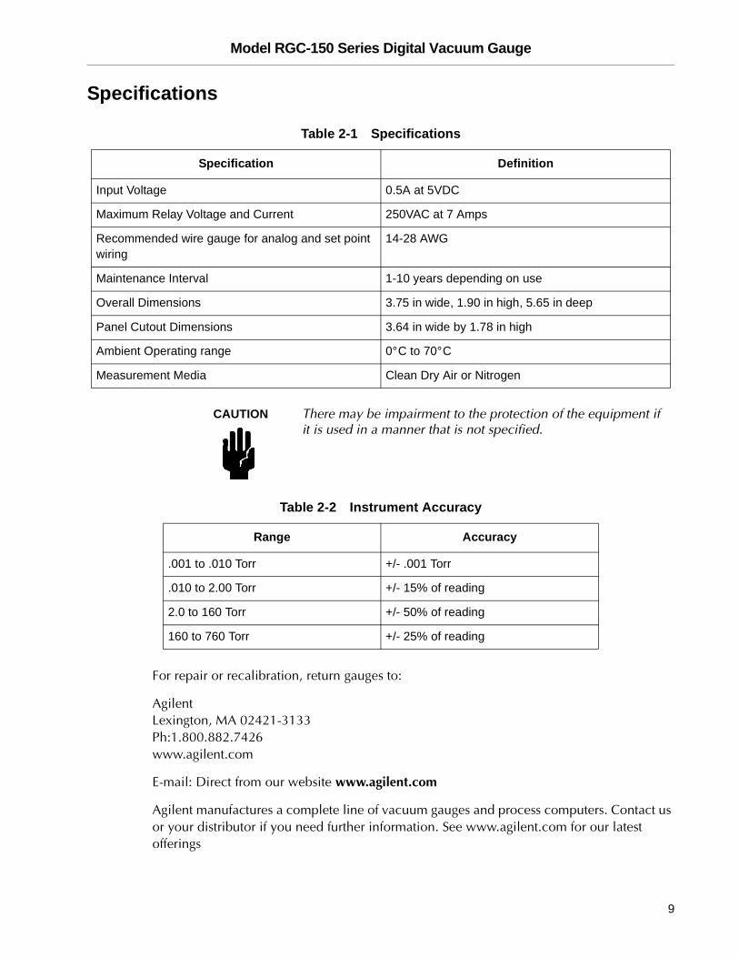
Specifications
CAUTION There may be impairment to the protection of the equipment if it is used in a manner that is not specified.
For repair or recalibration, return gauges to:
AgilentLexington, MA 02421-3133
Ph:1.800.882.7426
www.agilent.com
E-mail: Direct from our website www.agilent.com
Agilent manufactures a complete line of vacuum gauges and process computers. Contact us
or your distributor if you need further information. See www.agilent.com for our latest offerings
Table 2-1 Specifications
Specification Definition
Input Voltage 0.5A at 5VDC
Maximum Relay Voltage and Current 250VAC at 7 Amps
Recommended wire gauge for analog and set point wiring
14-28 AWG
Maintenance Interval 1-10 years depending on use
Overall Dimensions 3.75 in wide, 1.90 in high, 5.65 in deep
Panel Cutout Dimensions 3.64 in wide by 1.78 in high
Ambient Operating range 0° C to 70° C
Measurement Media Clean Dry Air or Nitrogen
Table 2-2 Instrument Accuracy
Range Accuracy
.001 to .010 Torr +/- .001 Torr
.010 to 2.00 Torr +/- 15% of reading
2.0 to 160 Torr +/- 50% of reading
160 to 760 Torr +/- 25% of reading

Model RGC-150 Series Digital Vacuum Gauge
This page intentionally left blank.
DR
AF
T 3
/27
/11
Model RGC-150 Series Digital Vacuum Gauge
This page intentionally left blank.
Pg 1/3
NORTH AMERICA:
Fax: 1 781 860 9252
Toll Free: 800 882 7426, Option 3
PACIFIC RIM:
please visit our website for individual
office information
http://www. .com
EUROPE:
Fax: 00 39 011 9979 330
Fax Free: 00 800 345 345 00
Toll Free: 00 800 234 234 00
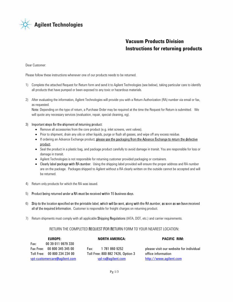
Vacuum Products Division
Instructions for returning products
Dear Customer:
Please follow these instructions whenever one of our products needs to be returned.
1) Complete the attached Request for Return form and send it to Agilent Technologies (see below), taking particular care to identify
all products that have pumped or been exposed to any toxic or hazardous materials.
2) After evaluating the information, Agilent Technologies will provide you with a Return Authorization (RA) number via email or fax,
as requested.
Note: Depending on the type of return, a Purchase Order may be required at the time the Request for Return is submitted. We
will quote any necessary services (evaluation, repair, special cleaning, eg).
3) Important steps for the shipment of returning product:
Remove all accessories from the core product (e.g. inlet screens, vent valves).
Prior to shipment, drain any oils or other liquids, purge or flush all gasses, and wipe off any excess residue.
If ordering an Advance Exchange product, please use the packaging from the Advance Exchange to return the defective
product.
Seal the product in a plastic bag, and package product carefully to avoid damage in transit. You are responsible for loss or
damage in transit.
Agilent Technologies is not responsible for returning customer provided packaging or containers.
Clearly label package with RA number. Using the shipping label provided will ensure the proper address and RA number
are on the package. Packages shipped to Agilent without a RA clearly written on the outside cannot be accepted and will
be returned.
4) Return only products for which the RA was issued.
5) Product being returned under a RA must be received within 15 business days.
6) Ship to the location specified on the printable label, which will be sent, along with the RA number, as soon as we have received
all of the required information. Customer is responsible for freight charges on returning product.
7) Return shipments must comply with all applicable Shipping Regulations (IATA, DOT, etc.) and carrier requirements.
RETURN THE COMPLETED REQUEST FOR RETURN FORM TO YOUR NEAREST LOCATION:
Req
uest for Return Health and Safety Certification
Model RGC-150 Series Digital Vacuum Gauge
This page intentionally left blank.
Pg 2/3
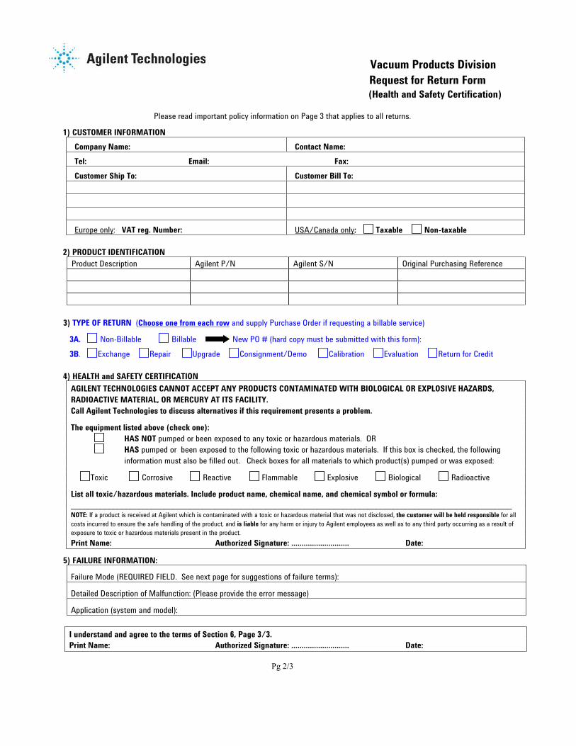
Vacuum Products Division
Request for Return Form
(Health and Safety Certification)
Please read important policy information on Page 3 that applies to all returns.
1) CUSTOMER INFORMATION
Company Name: Contact Name:
Tel: Email: Fax:
Customer Ship To: Customer Bill To:
Europe only: VAT reg. Number: USA/Canada only: Taxable Non-taxable
2) PRODUCT IDENTIFICATION
Product Description Agilent P/N Agilent S/N Original Purchasing Reference
3) TYPE OF RETURN (Choose one from each row and supply Purchase Order if requesting a billable service)
3A. Non-Billable Billable New PO # (hard copy must be submitted with this form):
3B. Exchange Repair Upgrade Consignment/Demo Calibration Evaluation Return for Credit
4) HEALTH and SAFETY CERTIFICATION
AGILENT TECHNOLOGIES CANNOT ACCEPT ANY PRODUCTS CONTAMINATED WITH BIOLOGICAL OR EXPLOSIVE HAZARDS,
RADIOACTIVE MATERIAL, OR MERCURY AT ITS FACILITY.
Call Agilent Technologies to discuss alternatives if this requirement presents a problem.
The equipment listed above (check one):
HAS NOT pumped or been exposed to any toxic or hazardous materials. OR
HAS pumped or been exposed to the following toxic or hazardous materials. If this box is checked, the following
information must also be filled out. Check boxes for all materials to which product(s) pumped or was exposed:
Toxic Corrosive Reactive Flammable Explosive Biological Radioactive
List all toxic/hazardous materials. Include product name, chemical name, and chemical symbol or formula:
________________________________________________________________________________________________________NOTE: If a product is received at Agilent which is contaminated with a toxic or hazardous material that was not disclosed, the customer will be held responsible for all
costs incurred to ensure the safe handling of the product, and is liable for any harm or injury to Agilent employees as well as to any third party occurring as a result of
exposure to toxic or hazardous materials present in the product.
Print Name: Authorized Signature: ………………………. Date:
5) FAILURE INFORMATION:
Failure Mode (REQUIRED FIELD. See next page for suggestions of failure terms):
Detailed Description of Malfunction: (Please provide the error message)
Application (system and model):
I understand and agree to the terms of Section 6, Page 3/3.
Print Name: Authorized Signature: ………………………. Date:
Model RGC-150 Series Digital Vacuum Gauge
This page intentionally left blank.
Pg 3/3
Vacuum Products Division
Request for Return Form
(Health and Safety Certification)
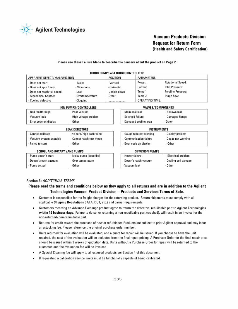
Please use these Failure Mode to describe the concern about the product on Page 2.
TURBO PUMPS and TURBO CONTROLLERS
APPARENT DEFECT/MALFUNCTION POSITION PARAMETERS
- Does not start - Noise - Vertical Power: Rotational Speed:
- Does not spin freely - Vibrations -Horizontal Current: Inlet Pressure:
- Does not reach full speed -Leak -Upside-down Temp 1: Foreline Pressure:
- Mechanical Contact -Overtemperature -Other: Temp 2: Purge flow:
- Cooling defective -Clogging …………………. OPERATING TIME:
ION PUMPS/CONTROLLERS VALVES/COMPONENTS
- Bad feedthrough - Poor vacuum - Main seal leak - Bellows leak
- Vacuum leak - High voltage problem - Solenoid failure - Damaged flange
- Error code on display - Other - Damaged sealing area -Other
LEAK DETECTORS INSTRUMENTS
- Cannot calibrate -No zero/high backround - Gauge tube not working - Display problem
- Vacuum system unstable - Cannot reach test mode - Communication failure - Degas not working
- Failed to start - Other - Error code on display - Other
SCROLL AND ROTARY VANE PUMPS DIFFUSION PUMPS
- Pump doesn’t start - Noisy pump (describe) - Heater failure - Electrical problem
- Doesn’t reach vacuum - Over temperature - Doesn’t reach vacuum - Cooling coil damage
- Pump seized - Other - Vacuum leak - Other
Section 6) ADDITIONAL TERMS
Please read the terms and conditions below as they apply to all returns and are in addition to the Agilent
Technologies Vacuum Product Division – Products and Services Terms of Sale.
Customer is responsible for the freight charges for the returning product. Return shipments must comply with all
applicable Shipping Regulations (IATA, DOT, etc.) and carrier requirements.
Customers receiving an Advance Exchange product agree to return the defective, rebuildable part to Agilent Technologies
within 15 business days. Failure to do so, or returning a non-rebuildable part (crashed), will result in an invoice for the
non-returned/non-rebuildable part.
Returns for credit toward the purchase of new or refurbished Products are subject to prior Agilent approval and may incur
a restocking fee. Please reference the original purchase order number.
Units returned for evaluation will be evaluated, and a quote for repair will be issued. If you choose to have the unit
repaired, the cost of the evaluation will be deducted from the final repair pricing. A Purchase Order for the final repair price
should be issued within 3 weeks of quotation date. Units without a Purchase Order for repair will be returned to the
customer, and the evaluation fee will be invoiced.
A Special Cleaning fee will apply to all exposed products per Section 4 of this document.
If requesting a calibration service, units must be functionally capable of being calibrated.

Model RGC-150 Series Digital Vacuum Gauge
This page intentionally left blank.

Agilent TechnologiesVacuum Product Division
United States & CanadaAgilent Technologies Vacuum Products Division 121 Hartwell Avenue Lexington, MA 02421 USA Tel: +1 781 861 7200Toll-Free: +1 800 882 7426 Fax: +1 871 860 5437
Benelux Agilent Technologies Vacuum Products Division Herculesweg 8 4338 PL MiddelburgTHE NETHERLANDS Tel: +31 118 671570Fax: +31 118 671569
China Agilent Technologies Vacuum Products Division Room 1648Central Tower South Wing Beijing Junefield Plaza No. 10 XuanWuMenWai Street Beijing 100052 P.R. CHINA Tel.: +86 (10) 6310 8550Toll-Free: 800 820 6556 Fax: +86 (10) 6310 0141
France Agilent Technologies Vacuum Products Division 7 avenue des Tropiques Z.A. de Courtaboeuf - B.P. 12 91941 Les Ulis cedex FRANCE Tel.: +33 (0) 1 69 86 38 84 Fax: +33 (0) 1 69 86 29 88
Germany & Austria Agilent Technologies Vacuum Products Division Alsfelder Strasse 6 Postfach 11 14 3564289 Darmstadt GERMANY Tel.: +49 (0) 6151 703 353Fax: +49 (0) 6151 703 302
India Agilent TechnologiesVacuum Product Division 205-A, “A” wing of Galleria,2nd floor, Hiranandani Gardens,Powai, Mumbai-400 076, IndiaTel.: +91 22-2570 8595 / 8597Fax: +91 22- 2570 8599
Italy Agilent Technologies Vacuum Products Division via F.lli Varian 54 10040 Leini, (Torino) ITALY Tel.: +39 011 997 9111Toll-Free: 00 800 234 234 00Fax: +39 011 997 9350
Japan Agilent Technologies Vacuum Products Division Sumitomo Shibaura Building 4-16-368th Floor4-16-36 Shibaura Minato-ku Tokyo 108 JAPAN Tel.: +81 3 5232 1253Toll-Free: 0120 655 040Fax: +81 3 5232 1710
Korea Agilent Technologies Vacuum Products Division Shinsa 2nd Bldg. 2F 966-5 Daechi-dong Kangnam-gu, Seoul KOREA 135-280 Tel.: +82 2 3452 2452Toll-Free: 080 222 2452Fax: +82 2 3452 2451
Mexico Agilent Technologies Vacuum Products Division Concepcion Beistegui No 109 Col Del Valle C.P. 03100 MEXICO, D.F. Tel.: +52 5 523 9465Fax: +52 5 523 9472
Southeast Asia Agilent Technologies Vacuum Products Division South East Asia (SEA) - Alex HoH/P: +601 2213 1253 Fax: +603 6733 8121
Singapore Agilent TechnologiesVacuum Products Division SingaporeUnit 10-04 HeliosBiopolis @ one-north11 Biopolis Way, 138667SingaporeH/P.: +65 92364988Fax: +65 64789603
Taiwan Agilent Technologies Vacuum Products Division 14F-6, No. 77, Hsin Tai Wu Road,Sec. 1Hsi chih, Taipei Hsien, Taiwan,R.O.C.Tel.: +886 2 2698 9555Toll Free: 0800 051 342Fax: +886 2 2698 9678
UK & Ireland Agilent Technologies Vacuum Products Division 6 Mead Road Oxford Industrial Park Tel.: +44 (0) 1865 291570Fax: +44 (0) 1865 291571