Embed Size (px)
Citation preview
Vacuum and air hose replacement -- replacing all the old, crusty air and vacuum hoses under and around
the intake manifold. Requires removing the intake manifold. While you've got the intake manifold off, it would be
good to do the PCV valve and the knock sensors. Both are much more difficult to replace when the intake manifold
is installed.
Throttle body and intake manifold removal
I suggest first removing the throttle body. The intake manifold+throttle body are pretty heavy, so I removed the
throttle body first. The FSM says to remove the alternator, but I don't recall having to do that. Keep track of where
all the hoses and bolts go as you remove parts.
1) Drain fuel from fuel rail as described in the FSM (see next page).
2) Remove throttle cable and cruise control cable.
3) Remove air intake pipe and place some protection over the MAF inlet so nothing damages the MAF.
4) Disconnect all hoses attaching to the throttle body. There are several air hoses and two water hoses. The hoses
are usually stuck pretty good. I found that in almost all cases, I was able to unstick the hoses by gently twisting the
hoses on the pipe with a pair of regular pliers.
5) Disconnect TPS electrical plug.
4) Remove the bolts securing the throttle body to the intake manifold.
6) As you pull the throttle body away, disconnect the IAC electrical plug from the bottom of the throttle body.
7) Disconnect the electrical plugs on the fuel injectors, the plug on the sensor going to the PS pump, and the plug for
the EGR sensor at the back left (as you face the motor) of the intake manifold.
8) Remove the fpr. The screws can be difficult to loosen. Be careful not to strip the screws.
9) Disconnect the EGR tube from the passenger side rear of the intake manifold.
10) Disconnect the hose going to the PCV valve. You can disconnect it at the crank case.
11) Pull the vacuum line going to the brake booster. Pull it at the intake manifold.
12) Disconnect the electrical plug that goes to the aux air controller on the driver side of the engine under the intake
manifold.
13) Remove all the bolts holding the metal fuel lines to the fuel rails. There are three sets of two bolts.
14) Disconnect the fuel lines and vapor line attaching to the intake manifold on the driver side of the intake
manifold.
15) Disconnect the vapor lines going to the charcoal canister. Disconnect the lines at the intake manifold.
16) Disconnect the plugs between the fuel injector harness and the main wiring harness. There are two plugs. These
are at the back of the engine on the passenger side.
17) Disconnect the two vacuum hoses that go from the EGR system to the metal vacuum lines at the passenger side
rear of the intake manifold.
18) Remove a bolt at the passenger side rear of the engine that secures the metal fuel lines to the cylinder head.
19) Remove the bolt securing the thick metal bracket to the driver side front of the intake manifold. The bracket
links the intake manifold and the AC compressor.
20) Remove the bolts securing the intake manifold to the risers. The intake manifold bolt at the driver side front of
the intake manifold will be difficult to reach. If you like, you can do as the FSM suggests and move the AC
compressor forward.
The intake manifold + metal fuel/air lines + injector wiring harness will all come off as one piece. You'll have to
slightly bend the metal fuel line to clear the air conditioner pipe at the driver side front of the intake manifold.
You'll probably have to reposition the injector wiring harness as you lift off the intake manifold. Take care not to
get any dirt/debris into the fuel rails on the engine or into the fuel pipes on the manifold! Any small amount
of debris can clog fuel injectors.
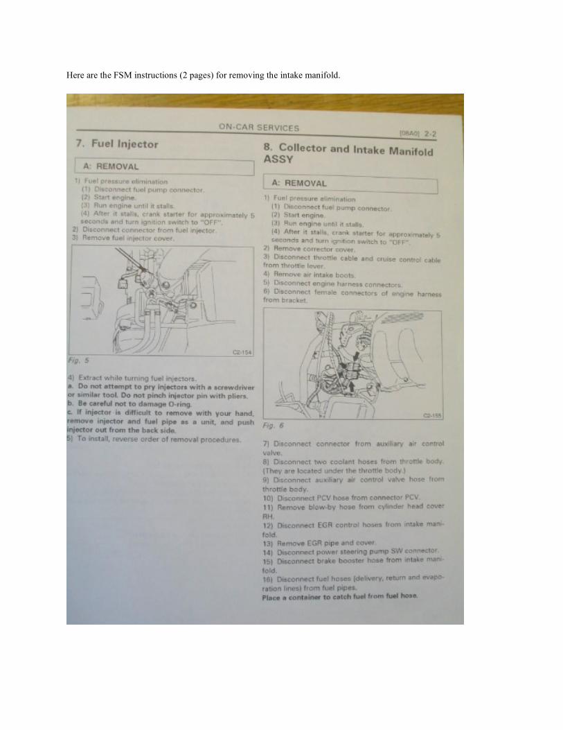
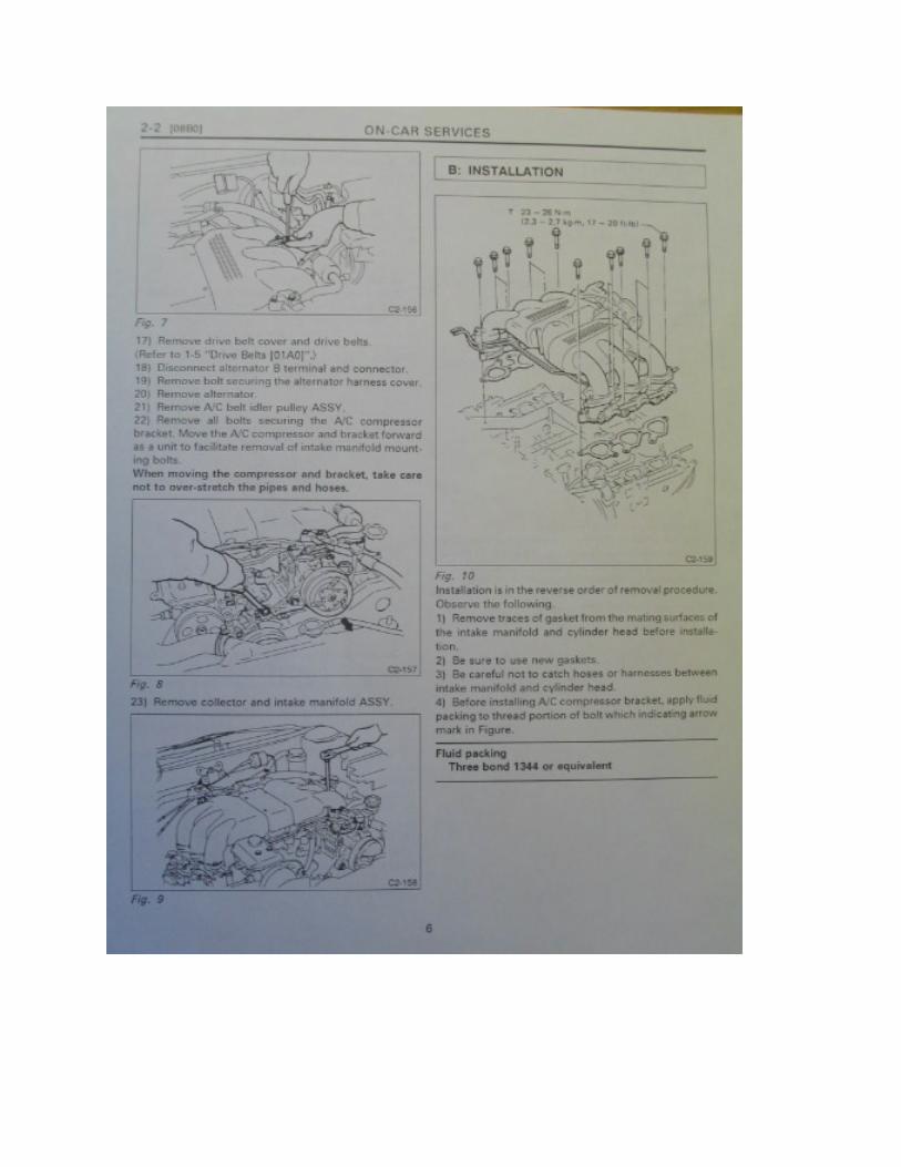
Here are the FSM instructions (2 pages) for removing the intake manifold.
Replacing the hoses
The hoses are usually stuck pretty good to the metal and plastic piping. I found that in almost all cases, I was able to
unstick the hoses by gently twisting the hoses on the pipe with a pair of regular pliers. Gently grip the hose where it
attaches to a pipe, and try gently twisting the hose. Spraying a little silicone lube would probably help too. Be very
careful when removing hose from the solenoids with plastic nipples. That plastic can and will break if too much
force is applied. It may be necessary to slice the hose lengthwise and peel it off the nipple. Below are two pictures
showing all the vacuum lines that I replaced under the manifold and on top of the engine.
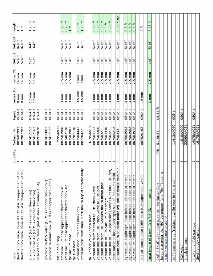
If you want, you can use non-Subaru hose to replace the 3 mm vacuum lines. It will save you quite a bit of money.
I went with viton rubber tubing which is rated to much higher operating temperatures (400F) than standard nitrile
rubber tubing (250F) sold at auto parts stores. I have listed a viton hose supplier in the table at the end of the
document.
As the end of this document, there is a list of hoses and other replaceable items with their part numbers.
Replacing other items
This would also be a good time to replace the PCV valve and the knock sensors. Both are very easy to access while
the intake manifold is off, while almost impossible to reach when the intake manifold is on. Knock sensors and
PCV valve are shown in the pictures below. Use teflon pipe tape when installing the new PCV valve.
Knock sensor torque value: 31 ft-lbs
The PCV valve has pipe threads.
It would also be good to replace the fuel rail o-rings. I have listed the part number for these in the table at the end of
the document.
Obtaining parts
I recommend buying your OEM Subaru parts from 1stsubaruparts.com. They are located in the Seattle area. They
have the best prices of any Subaru dealer. Their shipping prices are also the best. 1-866-528-5282. Ask for Jason
in Parts.
Installation of intake manifold
Installation is pretty much in the reverse order. Use new intake manifold and throttle body gaskets. The intake
manifold gaskets have little tabs that can be bent down to hold the gasket to the intake risers. Be sure that you've
installed all the hoses correctly and that all the electrical plugs have been reinstalled. After getting the manifold
reinstalled and everything buttoned up, flush the fuel rails with gasoline by turning the ignition to "on" but not
starting the car. Leave it at "on" for a few minutes.
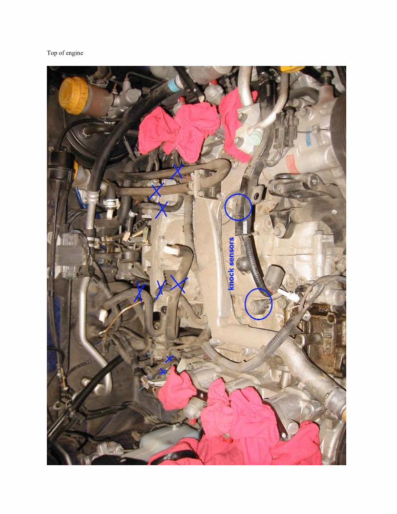
Top of engine
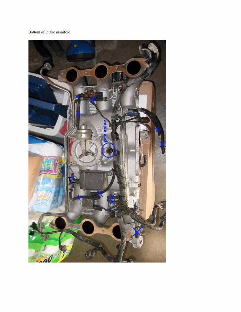
Bottom of intake manifold.
item
quantity
Subaru
PN
figure
m
etr
ic I
D
metr
ic O
D
SAE I
D
SAE O
D
length
thro
ttle
body w
ate
r hose #
1 (
OEM
is c
heaper
than v
iton)
1
807607992
063A-1
8 m
m
14 m
m
5/1
6"
9/1
6"
1 ft
thro
ttle
body w
ate
r hose #
2 (
OEM
is c
heaper
than v
iton)
1
807907202
063A-1
8 m
m
14 m
m
5/1
6"
9/1
6"
1 ft
aux a
ir h
ose #
1 (
OEM
is c
heaper
than v
iton)
1
807412152
036A-1
12 m
m
17 m
m
1/2
" 3/4
" 1.2
5 ft
aux a
ir h
ose #
2 (
OEM
is c
heaper
than v
iton)
1
807412162
036A-1
12 m
m
17 m
m
1/2
" 3/4
" 1.2
5 ft
hose c
lam
p f
or
hose (
not
in s
tock a
t Subaru
USA)
2
805919070
036A-1
pcv h
ose t
o P
CV v
alv
e (
OEM
is c
heaper
than v
iton)
1
807415082
082A-1
pcv h
ose t
o inta
ke b
ox (
OEM
is c
heaper
than v
iton)
1
807412172
082A-1
fuel pip
e o
-rin
g
3
17595AA000
061A-1
sm
all v
acuum
hose u
pper
rear
thro
ttle
body #
1
2
807503900
061A-1
3 m
m
7.5
mm
1/8
" 5/1
6"
0.7
5 ft
sm
all v
acuum
hose u
pper
rear
thro
ttle
body #
2
1
807403130
061A-1
3 m
m
7.5
mm
1/8
" 5/1
6"
0.7
5 ft
fpr
vacuum
hose
1
807503982
061A-1
3 m
m
7.5
mm
1/8
" 5/1
6"
1 ft
fpr
fuel hose
1
807707130
061A-1
vacuum
hose into
sm
all b
lack b
ox
1
807504442
061A-1
3.5
mm
9 m
m
1/8
" 3/8
" 0.5
ft
sm
all a
ir h
ose fro
m s
mall b
lack b
ox t
o t
op o
f th
rott
le b
ody
1
807204221
061A-1
3.5
mm
9 m
m
1/8
" 3/8
" 1.2
5 ft
IRIS
check v
alv
e (
not
a h
ose)
1
16195AA030
vacuum
lin
e fro
m m
anifold
to I
RIS
check v
alv
e
1
807503112
061A-1
3 m
m
7.5
mm
1/8
" 5/1
6"
0.2
5 ft
vacuum
lin
e fro
m I
RIS
check v
alv
e t
o I
RIS
box
1
807503360
061A-1
3 m
m
7.5
mm
1/8
" 5/1
6"
0.2
5 ft
vacuum
lin
e fro
m I
RIS
vacuum
box t
o m
eta
l pip
e
1
807503211
061A-1
3 m
m
7.5
mm
1/8
" 5/1
6"
0.2
5 ft
vacuum
lin
e t
o I
RIS
vacuum
dia
phra
gm
1
807503440
061A-1
3 m
m
7.5
mm
1/8
" 5/1
6"
0.5
ft
vacuum
lin
e t
o I
RIS
contr
oller
(sam
e P
N a
s into
IRIS
box)
1
807503211
061A-1
3 m
m
7.5
mm
1/8
" 5/1
6"
0.2
5 ft
short
fuel vent
hose u
nder
right
sid
e o
f in
take m
anifold
1
807505212
061A-1
vacuum
hose t
o s
ole
noid
under
left
sid
e o
f in
take m
anifold
2
807503431
061A-1
3 m
m
7.5
mm
1/8
" 5/1
6"
0.2
5 ft
x2
egr
vacuum
dia
phra
gm
hose b
ehin
d left
sid
e o
f m
oto
r 1
807503952
061A-1
3 m
m
7.5
mm
1/8
" 5/1
6"
0.5
ft
egr
vacuum
dia
phra
gm
hose b
ehin
d left
sid
e o
f m
oto
r 1
807503962
061A-1
3 m
m
7.5
mm
1/8
" 5/1
6"
0.5
ft
egr
vacuum
dia
phra
gm
hose b
ehin
d left
sid
e o
f m
oto
r 1
807503972
061A-1
3 m
m
7.5
mm
1/8
" 5/1
6"
0.5
ft
idle
air c
ontr
ol hose (
OEM
hose is c
heaper
than v
iton)
1
807520162
050A-1
19 m
m
2 ft
tota
l le
ngth
of 3 m
m I
D x
7.5
OD
mm
tubin
g
3 m
m
7.5
mm
1/8
" 5/1
6"
8.2
5 ft
1/8
" x 5
/16"
viton h
ose s
upplier:
M
cM
aste
r-C
arr
PN
: 5119K
31
$5.3
4/f
t
Be s
ure
to o
rder
the "
60"
duro
mete
r (a
ka "
firm
") t
ubin
g!!
htt
p:/
/ww
w.m
cm
aste
r.com
/
bell h
ousin
g p
lug (
repla
ce it
while y
our
in t
he a
rea)
1
11413AA040
005-1
PCV v
alv
e
1
11810AA000
050A-1
knock s
ensors
2
22060AA031
inta
ke m
anifold
gaskets
2
14075AA021
050A-1
thro
ttle
body g
asket
1
16175AA091


![INTAKE AIR SYSTEM HOSE ROUTING DIAGRAM [LF] · PDF fileINTAKE AIR SYSTEM HOSE ROUTING DIAGRAM [LF] Fig. 1: Identifying Intake Air System Hose Routing Diagram Courtesy of MAZDA MOTORS](https://img.pdfslide.us/doc/110x75/5abd7b367f8b9a7e418bb09e/intake-air-system-hose-routing-diagram-lf-air-system-hose-routing-diagram-lf.jpg)


![INTAKE AIR SYSTEM HOSE ROUTING DIAGRAM [LF]](https://img.pdfslide.us/doc/110x75/61da0a0704842a1ca1008100/intake-air-system-hose-routing-diagram-lf.jpg)