Embed Size (px)
Citation preview
user manualresolver option board
optbc
ac drivesvacon® nx

Local contacts: http://drives.danfoss.com/danfoss-drives/local-contacts/
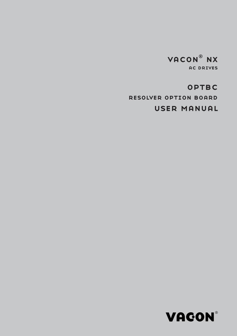
Table of contents Document code: DPD01362C
Date: 20.02.2018
1. Resolver option board OPT-BC ........................................................................................... 4
1.1 Note about absolute angle and different HW and SW versions ............................................... 4 1.2 Resolver basics ........................................................................................................................ 4 1.3 Resolver to digital conversion basics ....................................................................................... 5 1.4 Compatible resolver types........................................................................................................ 6 1.5 Resolver board features ........................................................................................................... 6
2. Configuration ..................................................................................................................... 7
2.1 Board parameters and monitoring values ............................................................................... 7 2.2 Connectors and jumpers .......................................................................................................... 8
3. Installation ....................................................................................................................... 14
3.1 Installing the option board ..................................................................................................... 14 3.2 Installing the resolver ............................................................................................................ 16 3.3 Additional cabling instructions ............................................................................................... 16
4. Diagnostics and troubleshooting ...................................................................................... 17
4.1 Fault handling ......................................................................................................................... 17 4.2 LED indicators ........................................................................................................................ 18 4.3 OPTBC Resolver error register bits ....................................................................................... 18
NOTE! You can download the English and French product manuals with applicable safety, warning
and caution information from http://drives.danfoss.com/knowledge-center/technical-
documentation/.
REMARQUE Vous pouvez télécharger les versions anglaise et française des manuels produit
sur le site http://drives.danfoss.com/knowledge-center/technical-documentation/.
4 Installation
Local contacts: http://drives.danfoss.com/danfoss-drives/local-contacts/
1
1. RESOLVER OPTION BOARD OPT-BC
This manual is valid for board versions VB00339i or later. The Resolver option board OPT-BC
provides the user with an interface to use resolvers as feedback device to VACON® NXP Drive. The
interface provides speed and position data. The OPT-BC includes also encoder simulation output
(HTL level) and secondary encoder input (HTL-level).
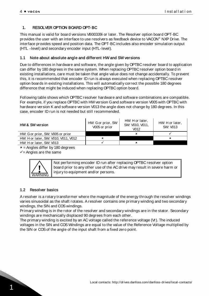
1.1 Note about absolute angle and different HW and SW versions
Due to differences in hardware and software, the angle given by OPTBC resolver board to application
can differ by 180 degrees in the same system. When replacing OPTBC resolver option board in
existing installations, care must be taken that angle value does not change accidentally. To prevent
this, it is recommended that encoder ID run is always executed when replacing OPTBC resolver
option boards in existing installations. This will automatically correct the possible 180 degrees
difference that might be induced when replacing OPTBC option board.
Following table shows which OPTBC resolver hardware and software combinations are compatible.
For example, if you replace OPTBC with HW version G and software version V005 with OPTBC with
hardware version K and software version V013 the angle does not change by 180 degrees. In this
case, encoder ID run is not needed but still recommended.
HW & SW version HW: G or prior, SW
V005 or prior
HW: H or later,
SW: V010, V011,
V012
HW: H or later,
SW: V013
HW: G or prior, SW: V005 or prior ✓
HW: H or later, SW: V010, V011, V012
HW: H or later, SW: V013 ✓
= Angles differ by 180 degrees
✓= Angles are the same
WARNING
Not performing encoder ID run after replacing OPTBC resolver option
board prior to any other use of the AC drive may result in severe harm or
injury to equipment and/or persons.
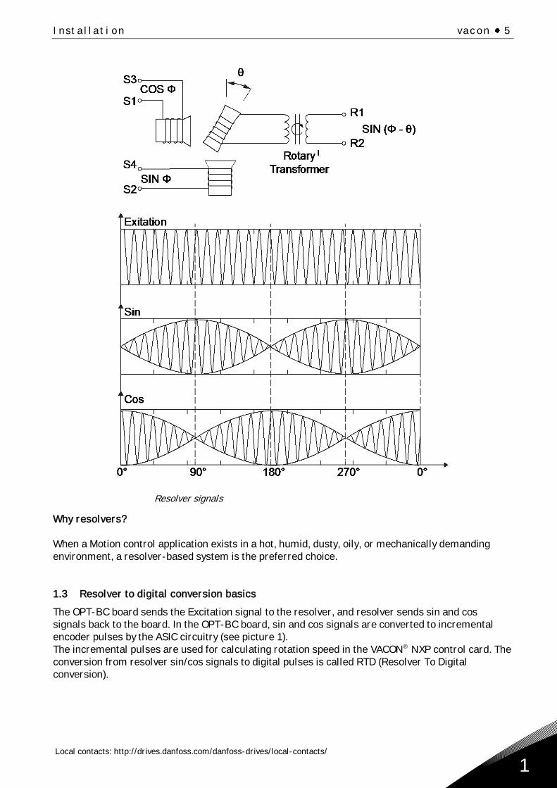
1.2 Resolver basics
A resolver is a rotary transformer where the magnitude of the energy through the resolver windings
varies sinusoidal as the shaft rotates. A resolver contains one primary winding and two secondary
windings, the SIN and COS windings.
Primary winding is in the rotor of the resolver and secondary windings are in the stator. Secondary
windings are mechanically displaced 90 degrees from each other.
The primary winding is excited by an AC voltage called the reference voltage (Vr). The induced
voltages in the SIN and COS Windings are equal to the value of the Reference Voltage multiplied by
the SIN or COS of the angle of the input shaft from a fixed zero point.
!
Installation vacon 5
Local contacts: http://drives.danfoss.com/danfoss-drives/local-contacts/
1
Resolver signals
Why resolvers?
When a Motion control application exists in a hot, humid, dusty, oily, or mechanically demanding
environment, a resolver-based system is the preferred choice.
1.3 Resolver to digital conversion basics
The OPT-BC board sends the Excitation signal to the resolver, and resolver sends sin and cos
signals back to the board. In the OPT-BC board, sin and cos signals are converted to incremental
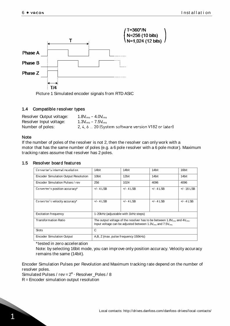
encoder pulses by the ASIC circuitry (see picture 1).
The incremental pulses are used for calculating rotation speed in the VACON® NXP control card. The
conversion from resolver sin/cos signals to digital pulses is called RTD (Resolver To Digital
conversion).
6 Installation
Local contacts: http://drives.danfoss.com/danfoss-drives/local-contacts/
1
Picture 1 Simulated encoder signals from RTD ASIC
1.4 Compatible resolver types
Resolver Output voltage: 1.8Vrms 4.0Vrms
Resolver Input voltage: 1.3Vrms 7.5Vrms
Number of poles:
Note
If the number of poles of the resolver is not 2, then the resolver can only work with a
motor that has the same number of poles (e.g. a 6 pole resolver with a 6 pole motor). Maximum
tracking rates assume that resolver has 2 poles.
NOTE
1.5 Resolver board features
14bit 14bit 14bit 16bit
Encoder Simulation Output Resolution 10bit 12bit 14bit 14bit
Encoder Simulation Pulses / rev 256 1024 4096 4096
osition accuracy* +/- 4 LSB +/- 4 LSB +/- 4 LSB +/- 16 LSB
elocity accuracy* +/- 4 LSB +/- 4 LSB +/- 4 LSB +/- 4 LSB
Excitation frequency 1-20kHz (adjustable with 1kHz steps)
Transformation Ratio The output voltage of the resolver has to be between 1.8Vrms and 4Vrms.
Input voltage can be adjusted between 1.3Vrms and 7.5Vrms.
Slots C
Encoder Simulation Output A,B, Z (max. pulse frequency 150kHz)
*tested in zero acceleration
Note: by selecting 16bit mode, you can improve only position accuracy. Velocity accuracy
remains the same (14bit).
Encoder Simulation Pulses per Revolution and Maximum tracking rate depend on the number of
resolver poles.
Simulated Pulses / rev = 2R ∙ Resolver_Poles / 8
R = Encoder simulation output resolution
Installation vacon 7
Local contacts: http://drives.danfoss.com/danfoss-drives/local-contacts/
2
2. CONFIGURATION
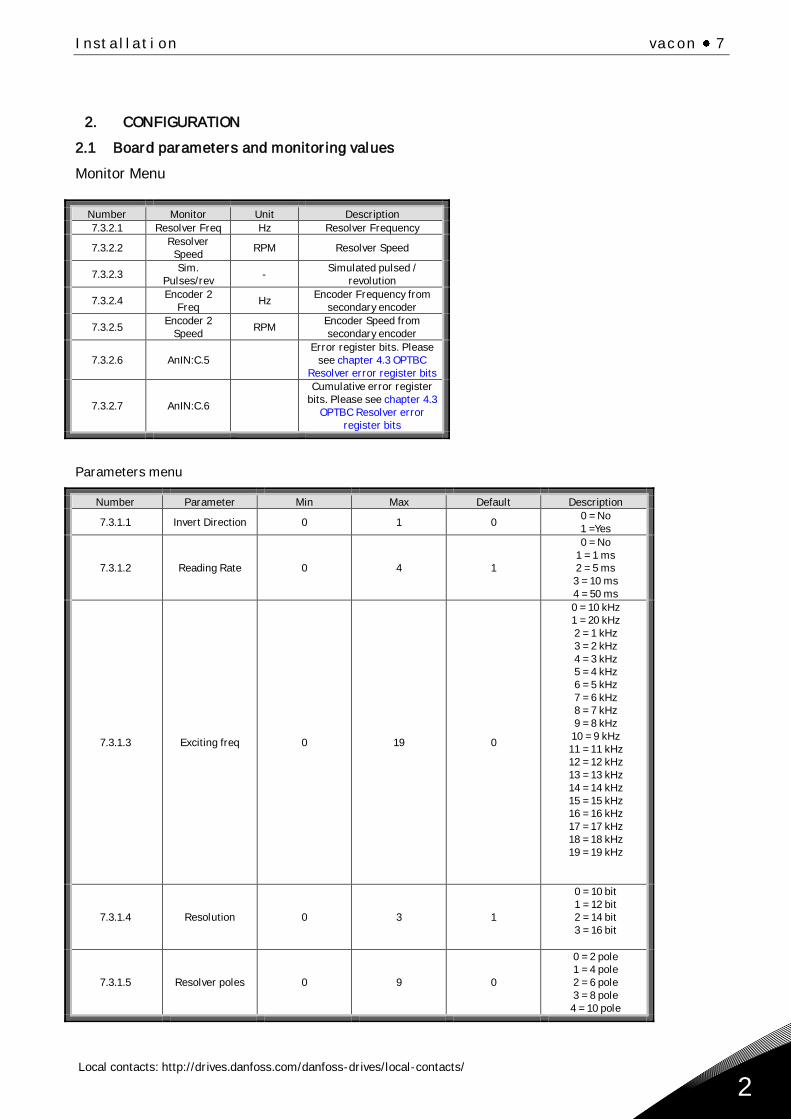
2.1 Board parameters and monitoring values
Monitor Menu
Number Monitor Unit Description
7.3.2.1 Resolver Freq Hz Resolver Frequency
7.3.2.2 Resolver
Speed RPM Resolver Speed
7.3.2.3 Sim.
Pulses/rev -
Simulated pulsed /
revolution
7.3.2.4 Encoder 2
Freq Hz
Encoder Frequency from
secondary encoder
7.3.2.5 Encoder 2
Speed RPM
Encoder Speed from
secondary encoder
7.3.2.6 AnIN:C.5
Error register bits. Please
see chapter 4.3 OPTBC
Resolver error register bits
7.3.2.7 AnIN:C.6
Cumulative error register
bits. Please see chapter 4.3
OPTBC Resolver error
register bits
Parameters menu
Number Parameter Min Max Default Description
7.3.1.1 Invert Direction 0 1 0 0 = No
1 =Yes
7.3.1.2 Reading Rate 0 4 1
0 = No
1 = 1 ms
2 = 5 ms
3 = 10 ms
4 = 50 ms
7.3.1.3 Exciting freq 0 19 0
0 = 10 kHz
1 = 20 kHz
2 = 1 kHz
3 = 2 kHz
4 = 3 kHz
5 = 4 kHz
6 = 5 kHz
7 = 6 kHz
8 = 7 kHz
9 = 8 kHz
10 = 9 kHz
11 = 11 kHz
12 = 12 kHz
13 = 13 kHz
14 = 14 kHz
15 = 15 kHz
16 = 16 kHz
17 = 17 kHz
18 = 18 kHz
19 = 19 kHz
7.3.1.4 Resolution 0 3 1
0 = 10 bit
1 = 12 bit
2 = 14 bit
3 = 16 bit
7.3.1.5 Resolver poles 0 9 0
0 = 2 pole
1 = 4 pole
2 = 6 pole
3 = 8 pole
4 = 10 pole
8 Installation
Local contacts: http://drives.danfoss.com/danfoss-drives/local-contacts/
2
5 = 12 pole
6 = 14 pole
7 = 16 pole
8 = 18 pole
9 = 20 pole
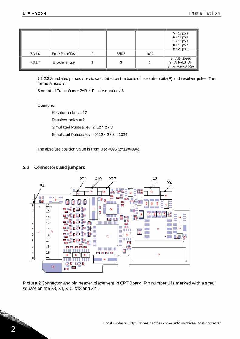
7.3.1.6 Enc 2 Pulse/Rev 0 65535 1024
7.3.1.7 Encoder 2 Type 1 3 1
1 = A,B=Speed
2 = A=Ref,B=Dir
3 = A=Forw,B=Rev
7.3.2.3 Simulated pulses / rev is calculated on the basis of resolution bits(R) and resolver poles. The
formula used is:
Simulated Pulses/rev = 2^R * Resolver poles / 8
.
Example:
Resolution bits = 12
Resolver poles = 2
Simulated Pulses/rev=2^12 * 2 / 8
Simulated Pulses/rev = 2^12 * 2 / 8 = 1024
The absolute position value is from 0 to 4095 (2^12=4096).
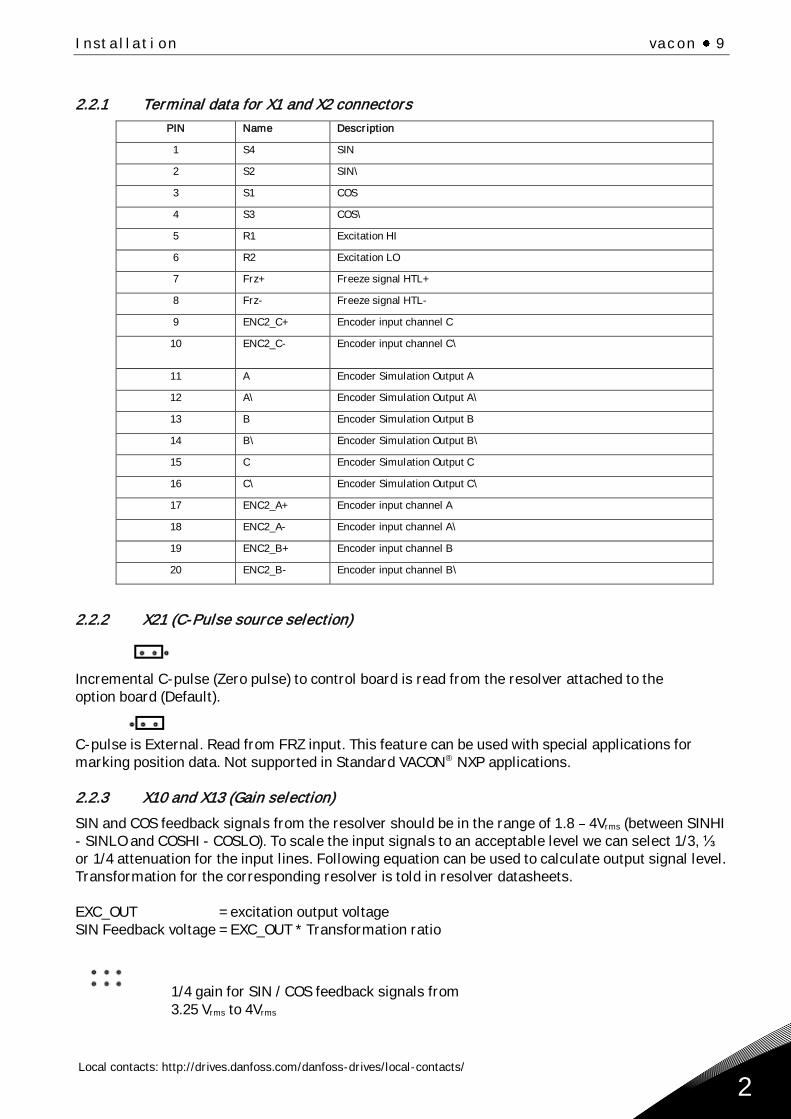
2.2 Connectors and jumpers
Picture 2 Connector and pin header placement in OPT Board. Pin number 1 is marked with a small
square on the X3, X4, X10, X13 and X21.
1
2
3
4
5
6
7
8
9
10
X1
X21 X10 X13 X3 X4
11
12
13
14
15
16
17
18
19
20
Installation vacon 9
Local contacts: http://drives.danfoss.com/danfoss-drives/local-contacts/
2
2.2.1 Terminal data for X1 and X2 connectors
PIN Name Description
1 S4 SIN
2 S2 SIN\
3 S1 COS
4 S3 COS\
5 R1 Excitation HI
6 R2 Excitation LO
7 Frz+ Freeze signal HTL+
8 Frz- Freeze signal HTL-
9 ENC2_C+ Encoder input channel C
10 ENC2_C- Encoder input channel C\
11 A Encoder Simulation Output A
12 A\ Encoder Simulation Output A\
13 B Encoder Simulation Output B
14 B\ Encoder Simulation Output B\
15 C Encoder Simulation Output C
16 C\ Encoder Simulation Output C\
17 ENC2_A+ Encoder input channel A
18 ENC2_A- Encoder input channel A\
19 ENC2_B+ Encoder input channel B
20 ENC2_B- Encoder input channel B\
2.2.2 X21 (C-Pulse source selection)
Incremental C-pulse (Zero pulse) to control board is read from the resolver attached to the
option board (Default).
C-pulse is External. Read from FRZ input. This feature can be used with special applications for
marking position data. Not supported in Standard VACON® NXP applications.
2.2.3 X10 and X13 (Gain selection)
SIN and COS feedback signals from the resolver should be in the range of 1.8 4Vrms (between SINHI
- SINLO and COSHI - COSLO). To scale the input signals to an acceptable level we can select 1/3, ⅓
or 1/4 attenuation for the input lines. Following equation can be used to calculate output signal level.
Transformation for the corresponding resolver is told in resolver datasheets.
EXC_OUT = excitation output voltage
SIN Feedback voltage = EXC_OUT * Transformation ratio
1/4 gain for SIN / COS feedback signals from
3.25 Vrms to 4Vrms
10 Installation
Local contacts: http://drives.danfoss.com/danfoss-drives/local-contacts/
2
1/3 gain for SIN / COS feedback signals from
2.4 Vrms to 3.24Vrms
1/2 gain for SIN / COS feedback signals from
1.8 Vrms to 2.39Vrms
X13 sets SIN attenuation and X10 sets COS attenuation. SIN and COS input pairs should all have the
same attenuation to keep signals symmetrical.
For example, a resolver that is rated for 5.6Vrms excitation and has a transformation ratio of 0.485
gives output voltage of 2.72Vrms. Excitation voltage and corresponding settings are selected from the
table 1 in chapter 2.2.4. In this case exact match is found. Resolver output voltage of 2.72V Vrms fits to
the signal range of 1/3 attenuation.
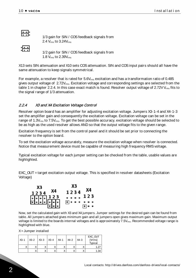
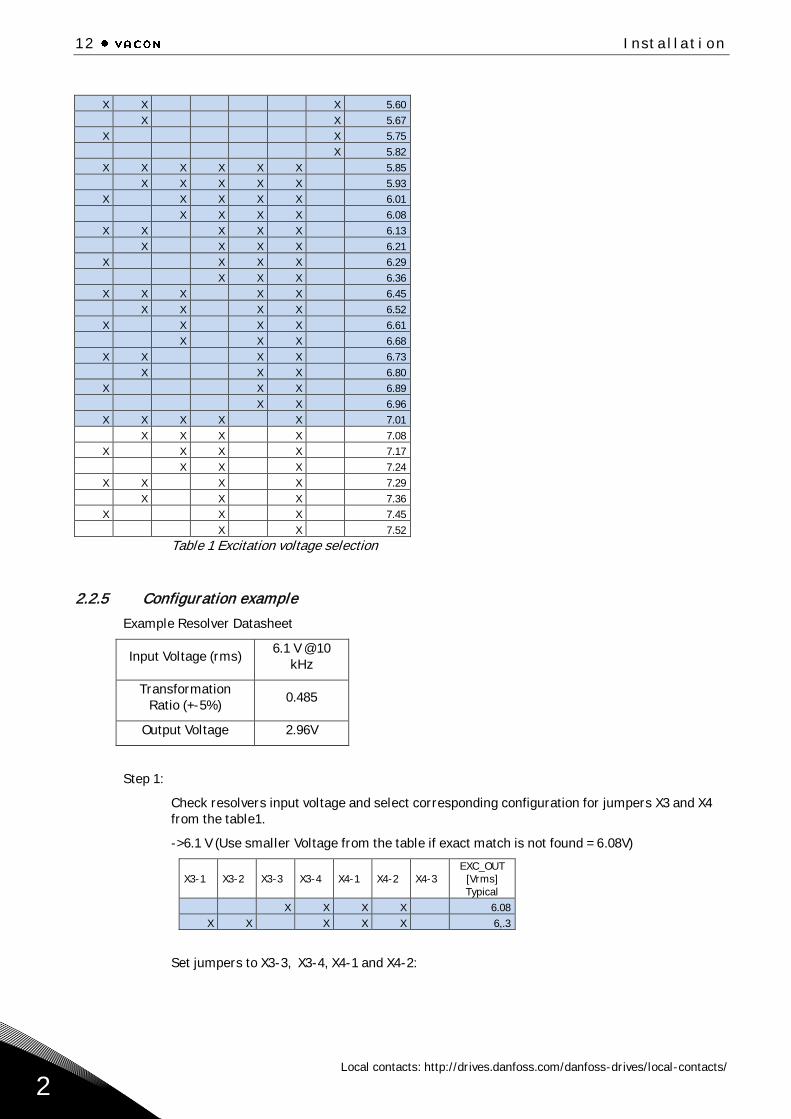
2.2.4 X3 and X4 Excitation Voltage Control
Resolver option board has an amplifier for adjusting excitation voltage. Jumpers X3-1-4 and X4-1-3
set the amplifier gain and consequently the excitation voltage. Excitation voltage can be set in the
range of 1.3Vrms to 7.5Vrms. To get the best possible accuracy, excitation voltage should be selected to
be as high as the used resolver allows AND so that the output voltage fits to the given range.
Excitation frequency is set from the control panel and it should be set prior to connecting the
resolver to the option board.
To set the excitation voltage accurately, measure the excitation voltage when resolver is connected.
Notice that measurement device must be capable of measuring high frequency RMS voltage.
Typical excitation voltage for each jumper setting can be checked from the table, usable values are
highlighted.
EXC_OUT = target excitation output voltage. This is specified in resolver datasheets (Excitation
Voltage)
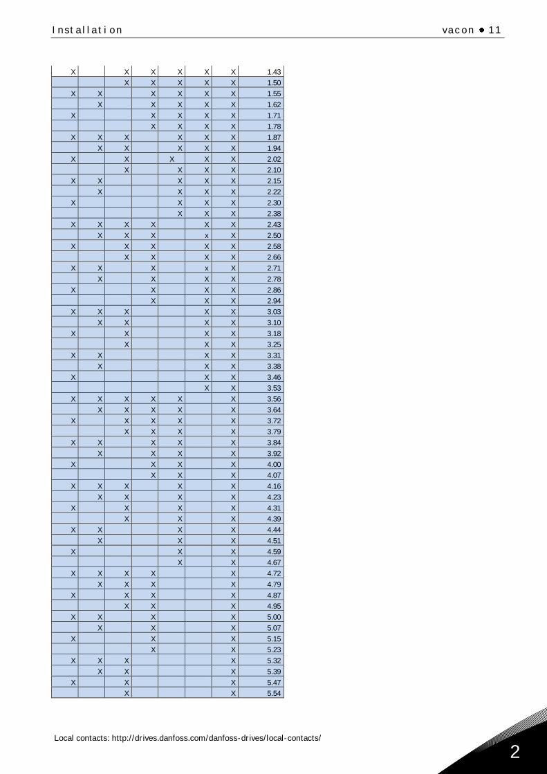
Now, set the calculated gain with X3 and X4 jumpers. Jumper settings for the desired gain can be found from
table. All jumpers attached gives minimum gain and all jumpers open gives maximum gain. Maximum output
voltage is limited to the boards internal voltages and is approximately 7.5Vrms. Recommended voltage range is
highlighted with blue.
X = Jumper installed
X3-1
X3-2
X3-3
X3-4
X4-1
X4-2
X4-3
EXC_OUT
[Vrms]
Typical
X X X X X X X 1.27
X X X X X X 1.34
Installation vacon 11
Local contacts: http://drives.danfoss.com/danfoss-drives/local-contacts/
2
X X X X X X 1.43
X X X X X 1.50
X X X X X X 1.55
X X X X X 1.62
X X X X X 1.71
X X X X 1.78
X X X X X X 1.87
X X X X X 1.94
X X X X X 2.02
X X X X 2.10
X X X X X 2.15
X X X X 2.22
X X X X 2.30
X X X 2.38
X X X X X X 2.43
X X X x X 2.50
X X X X X 2.58
X X X X 2.66
X X X x X 2.71
X X X X 2.78
X X X X 2.86
X X X 2.94
X X X X X 3.03
X X X X 3.10
X X X X 3.18
X X X 3.25
X X X X 3.31
X X X 3.38
X X X 3.46
X X 3.53
X X X X X X 3.56
X X X X X 3.64
X X X X X 3.72
X X X X 3.79
X X X X X 3.84
X X X X 3.92
X X X X 4.00
X X X 4.07
X X X X X 4.16
X X X X 4.23
X X X X 4.31
X X X 4.39
X X X X 4.44
X X X 4.51
X X X 4.59
X X 4.67
X X X X X 4.72
X X X X 4.79
X X X X 4.87
X X X 4.95
X X X X 5.00
X X X 5.07
X X X 5.15
X X 5.23
X X X X 5.32
X X X 5.39
X X X 5.47
X X 5.54
12 Installation
Local contacts: http://drives.danfoss.com/danfoss-drives/local-contacts/
2
X X X 5.60
X X 5.67
X X 5.75
X 5.82
X X X X X X
5.85
X X X X X
5.93
X X X X X
6.01
X X X X
6.08
X X X X X
6.13
X X X X
6.21
X X X X
6.29
X X X
6.36
X X X X X
6.45
X X X X
6.52
X X X X
6.61
X X X
6.68
X X X X
6.73
X X X
6.80
X X X
6.89
X X
6.96
X X X X X
7.01
X X X X
7.08
X X X X
7.17
X X X
7.24
X X X X
7.29
X X X
7.36
X X X
7.45
X X
7.52
Table 1 Excitation voltage selection
2.2.5 Configuration example
Example Resolver Datasheet
Input Voltage (rms) 6.1 V @ 10
kHz
Transformation
Ratio (+-5%) 0.485
Output Voltage 2.96V
Step 1:
Check resolvers input voltage and select corresponding configuration for jumpers X3 and X4
from the table1.
->6.1 V (Use smaller Voltage from the table if exact match is not found = 6.08V)
X3-1
X3-2
X3-3
X3-4
X4-1
X4-2
X4-3
EXC_OUT
[Vrms]
Typical
X X X X
6.08
X X X X X
6,.3
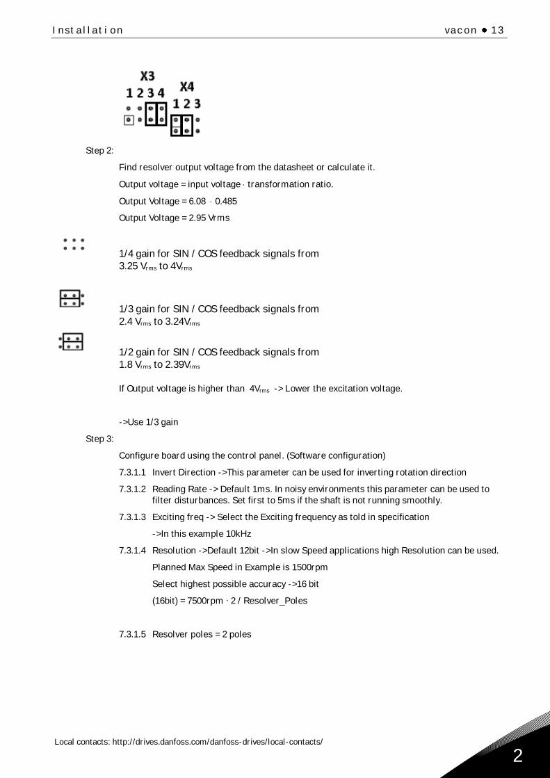
Set jumpers to X3-3, X3-4, X4-1 and X4-2:
Installation vacon 13
Local contacts: http://drives.danfoss.com/danfoss-drives/local-contacts/
2
Step 2:
Find resolver output voltage from the datasheet or calculate it.
Output voltage = input voltage transformation ratio.
Output Voltage = 6.08 0.485
Output Voltage = 2.95 Vrms
1/4 gain for SIN / COS feedback signals from
3.25 Vrms to 4Vrms
1/3 gain for SIN / COS feedback signals from
2.4 Vrms to 3.24Vrms
1/2 gain for SIN / COS feedback signals from
1.8 Vrms to 2.39Vrms
If Output voltage is higher than 4Vrms -> Lower the excitation voltage.
->Use 1/3 gain
Step 3:
Configure board using the control panel. (Software configuration)
7.3.1.1 Invert Direction ->This parameter can be used for inverting rotation direction
7.3.1.2 Reading Rate -> Default 1ms. In noisy environments this parameter can be used to
filter disturbances. Set first to 5ms if the shaft is not running smoothly.
7.3.1.3 Exciting freq -> Select the Exciting frequency as told in specification
->In this example 10kHz
7.3.1.4 Resolution ->Default 12bit ->In slow Speed applications high Resolution can be used.
Planned Max Speed in Example is 1500rpm
Select highest possible accuracy ->16 bit
(16bit) = 7500rpm ∙ 2 / Resolver_Poles
7.3.1.5 Resolver poles = 2 poles
14 Installation
Local contacts: http://drives.danfoss.com/danfoss-drives/local-contacts/
3
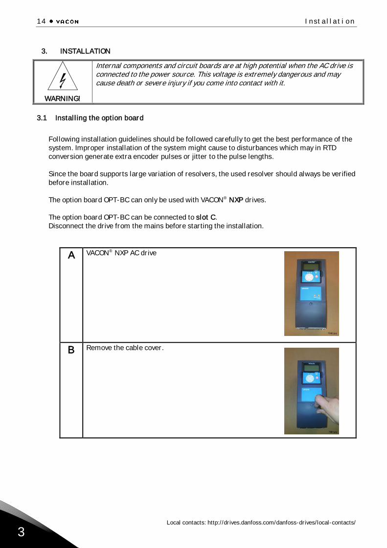
3. INSTALLATION
WARNING!
Internal components and circuit boards are at high potential when the AC drive is connected to the power source. This voltage is extremely dangerous and may cause death or severe injury if you come into contact with it.
3.1 Installing the option board
Following installation guidelines should be followed carefully to get the best performance of the
system. Improper installation of the system might cause to disturbances which may in RTD
conversion generate extra encoder pulses or jitter to the pulse lengths.
Since the board supports large variation of resolvers, the used resolver should always be verified
before installation.
The option board OPT-BC can only be used with VACON® NXP drives.
The option board OPT-BC can be connected to slot C.
Disconnect the drive from the mains before starting the installation.
A VACON® NXP AC drive
B Remove the cable cover.
Installation vacon 15
Local contacts: http://drives.danfoss.com/danfoss-drives/local-contacts/
3
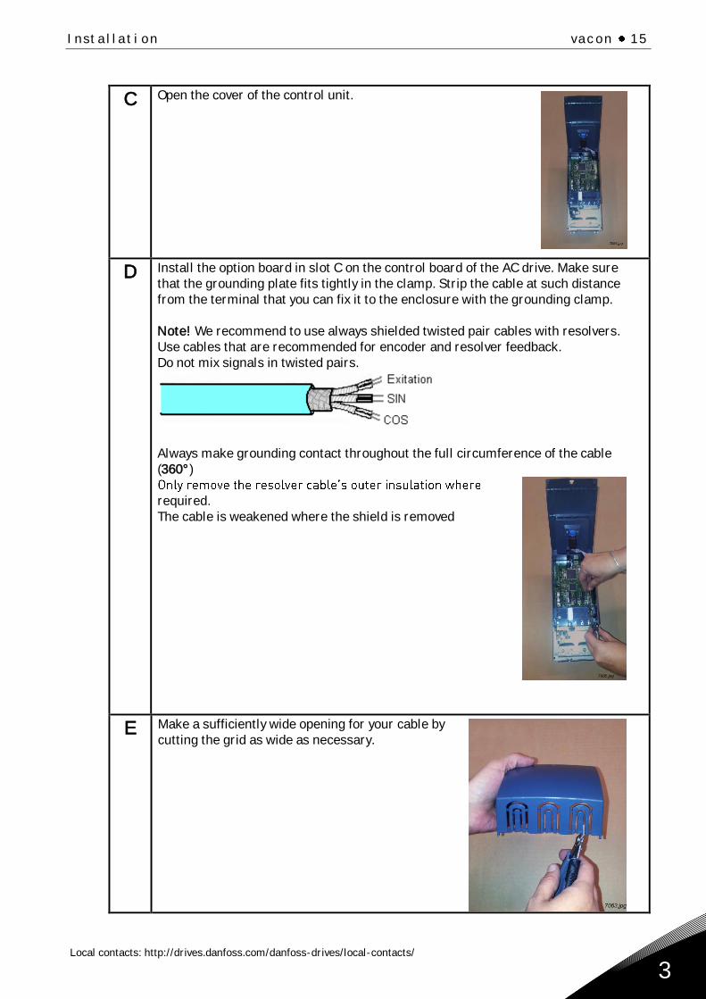
C Open the cover of the control unit.
D Install the option board in slot C on the control board of the AC drive. Make sure
that the grounding plate fits tightly in the clamp. Strip the cable at such distance
from the terminal that you can fix it to the enclosure with the grounding clamp.
Note! We recommend to use always shielded twisted pair cables with resolvers.
Use cables that are recommended for encoder and resolver feedback.
Do not mix signals in twisted pairs.
Always make grounding contact throughout the full circumference of the cable
(360°)
required.
The cable is weakened where the shield is removed
E Make a sufficiently wide opening for your cable by
cutting the grid as wide as necessary.
16 Installation
Local contacts: http://drives.danfoss.com/danfoss-drives/local-contacts/
3
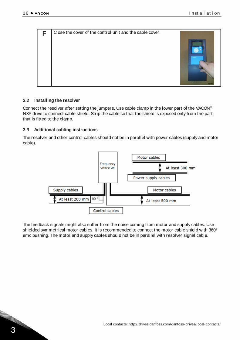
F Close the cover of the control unit and the cable cover.
3.2 Installing the resolver
Connect the resolver after setting the jumpers. Use cable clamp in the lower part of the VACON®
NXP drive to connect cable shield. Strip the cable so that the shield is exposed only from the part
that is fitted to the clamp.
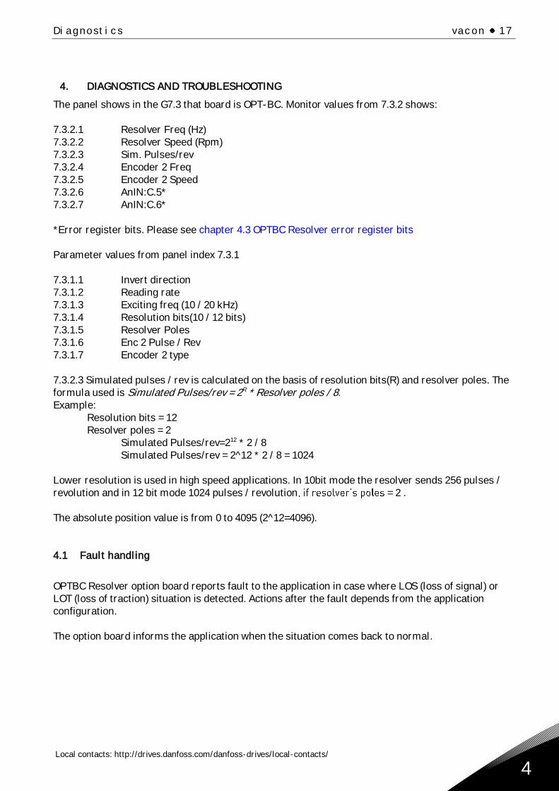
3.3 Additional cabling instructions
The resolver and other control cables should not be in parallel with power cables (supply and motor
cable).
The feedback signals might also suffer from the noise coming from motor and supply cables. Use
shielded symmetrical motor cables. It is recommended to connect the motor cable shield with 360°
emc bushing. The motor and supply cables should not be in parallel with resolver signal cable.
Diagnostics vacon 17
Local contacts: http://drives.danfoss.com/danfoss-drives/local-contacts/
4
4. DIAGNOSTICS AND TROUBLESHOOTING
The panel shows in the G7.3 that board is OPT-BC. Monitor values from 7.3.2 shows:
7.3.2.1 Resolver Freq (Hz)
7.3.2.2 Resolver Speed (Rpm)
7.3.2.3 Sim. Pulses/rev
7.3.2.4 Encoder 2 Freq
7.3.2.5 Encoder 2 Speed
7.3.2.6 AnIN:C.5*
7.3.2.7 AnIN:C.6*
*Error register bits. Please see chapter 4.3 OPTBC Resolver error register bits
Parameter values from panel index 7.3.1
7.3.1.1 Invert direction
7.3.1.2 Reading rate
7.3.1.3 Exciting freq (10 / 20 kHz)
7.3.1.4 Resolution bits(10 / 12 bits)
7.3.1.5 Resolver Poles
7.3.1.6 Enc 2 Pulse / Rev
7.3.1.7 Encoder 2 type
7.3.2.3 Simulated pulses / rev is calculated on the basis of resolution bits(R) and resolver poles. The
formula used is Simulated Pulses/rev = 2R * Resolver poles / 8.
Example:
Resolution bits = 12
Resolver poles = 2
Simulated Pulses/rev=212 * 2 / 8
Simulated Pulses/rev = 2^12 * 2 / 8 = 1024
Lower resolution is used in high speed applications. In 10bit mode the resolver sends 256 pulses /
revolution and in 12 bit mode 1024 pulses / revolution = 2 .
The absolute position value is from 0 to 4095 (2^12=4096).
4.1 Fault handling
OPTBC Resolver option board reports fault to the application in case where LOS (loss of signal) or
LOT (loss of traction) situation is detected. Actions after the fault depends from the application
configuration.
The option board informs the application when the situation comes back to normal.
18 Diagnostics
Local contacts: http://drives.danfoss.com/danfoss-drives/local-contacts/
4
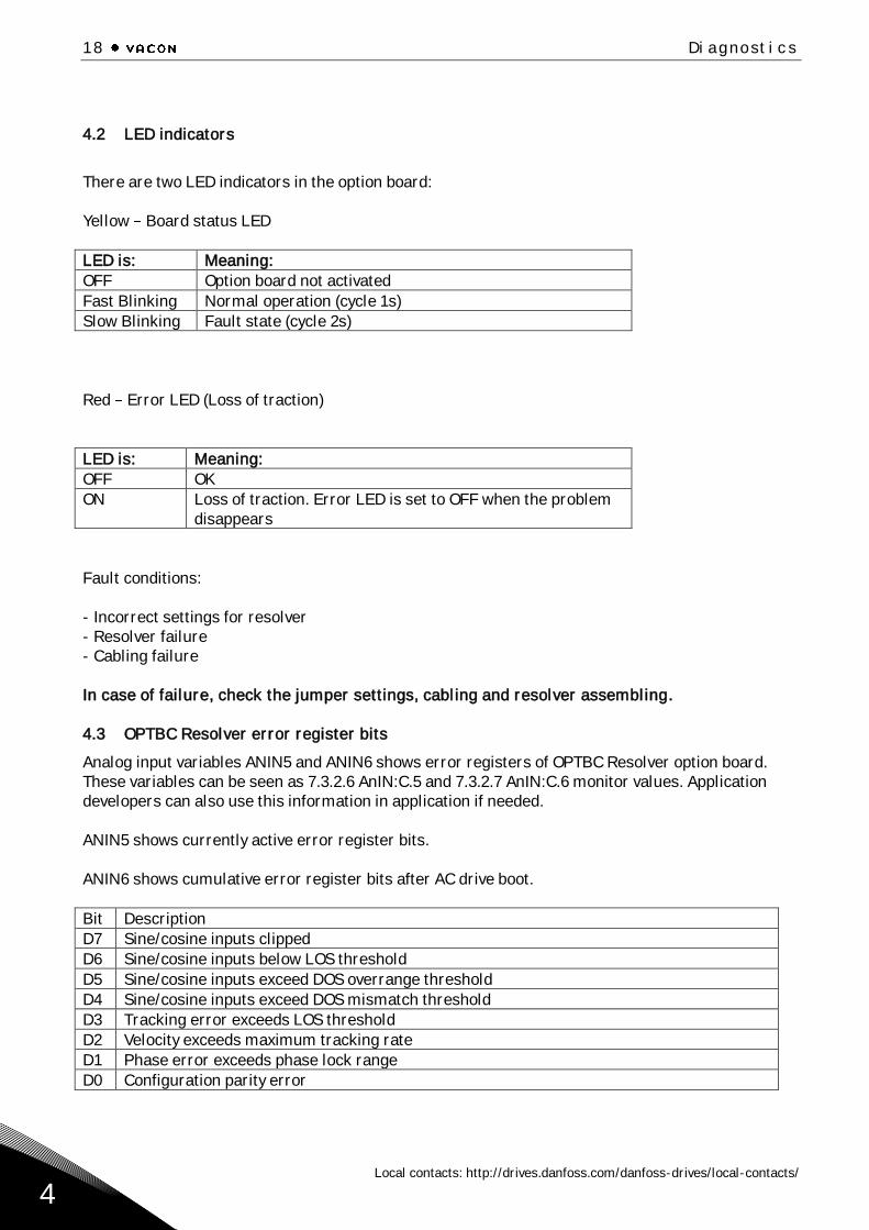
4.2 LED indicators
There are two LED indicators in the option board:
Yellow Board status LED
LED is: Meaning:
OFF Option board not activated
Fast Blinking Normal operation (cycle 1s)
Slow Blinking Fault state (cycle 2s)
Red Error LED (Loss of traction)
LED is: Meaning:
OFF OK
ON Loss of traction. Error LED is set to OFF when the problem
disappears
Fault conditions:
- Incorrect settings for resolver
- Resolver failure
- Cabling failure
In case of failure, check the jumper settings, cabling and resolver assembling.
4.3 OPTBC Resolver error register bits
Analog input variables ANIN5 and ANIN6 shows error registers of OPTBC Resolver option board.
These variables can be seen as 7.3.2.6 AnIN:C.5 and 7.3.2.7 AnIN:C.6 monitor values. Application
developers can also use this information in application if needed.
ANIN5 shows currently active error register bits.
ANIN6 shows cumulative error register bits after AC drive boot.
Bit Description
D7 Sine/cosine inputs clipped
D6 Sine/cosine inputs below LOS threshold
D5 Sine/cosine inputs exceed DOS overrange threshold
D4 Sine/cosine inputs exceed DOS mismatch threshold
D3 Tracking error exceeds LOS threshold
D2 Velocity exceeds maximum tracking rate
D1 Phase error exceeds phase lock range
D0 Configuration parity error

Document ID:
DPD01362CRev. C
Sales code: DOC-OPTBC+DLUK
Vacon LtdMember of the Danfoss GroupRunsorintie 765380 VaasaFinland
www.danfoss.com