Embed Size (px)
Citation preview

ac drivesvacon® 100 x
vacon® 100 industrial
application manual

PREFACEDOCUMENT DETAILS
Document ID: DPD00927J
Date: 17.5.2017
Software version: FW0072V026
ABOUT THIS MANUAL
This manual is copyright of Vacon Ltd. All Rights Reserved. The manual is subject to changewithout prior notice. The original language of these instructions is English.
In this manual, you can read about the functions of the VACON® AC drive and how to use thedrive. The manual has the same structure than the menu of the drive (chapters 1 and 4-8).
Chapter 1, Quick Startup Guide
• How to start the work with the control panel.
Chapter 2, Wizards
• Making a selection of the application configuration.• Setting up an application quickly.• The different applications with examples.
Chapter 3, User Interfaces
• The display types and how to use the control panel.• The PC tool VACON® Live.• The functions of the fieldbus.
Chapter 4, Monitoring menu
• Data on the monitoring values.
Chapter 5, Parameter menu
• A list of all the parameters of the drive.
Chapter 6, Diagnostics menu
Chapter 7, I/O and Hardware menu
Chapter 8, User settings, favourites and user level menus
Chapter 9, Monitoring value descriptions
Chapter 10, Parameter descriptions
PREFACE VACON · 3
LOCAL CONTACTS: HTTP://DRIVES.DANFOSS.COM/DANFOSS-DRIVES/LOCAL-CONTACTS/
• How to use the parameters.• Digital and analogue input programming.• Application-specific functions.
Chapter 11, Fault tracing
• The faults and their causes.• Resetting the faults.
Chapter 12, Appendix 1
• Data on the different default values of the applications.
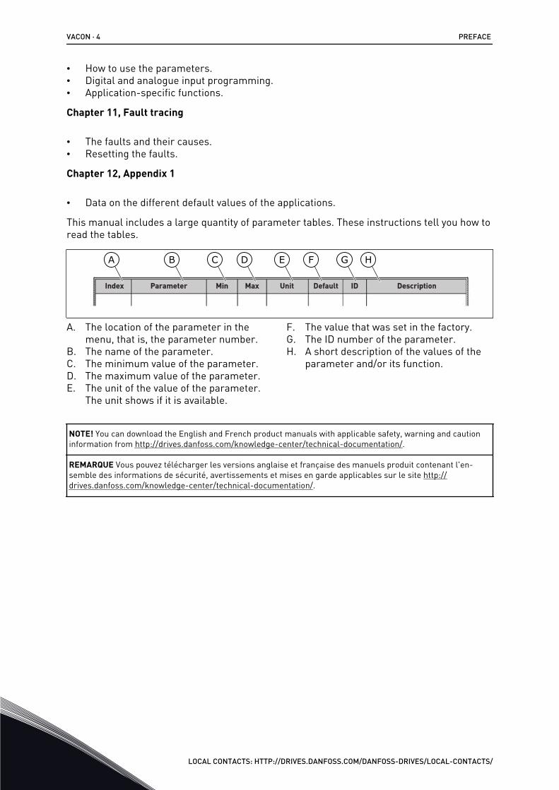
This manual includes a large quantity of parameter tables. These instructions tell you how toread the tables.
Index Min Max Unit Default ID DescriptionParameter
A B C D E F G H
A. The location of the parameter in themenu, that is, the parameter number.
B. The name of the parameter.C. The minimum value of the parameter.D. The maximum value of the parameter.E. The unit of the value of the parameter.
The unit shows if it is available.
F. The value that was set in the factory.G. The ID number of the parameter.H. A short description of the values of the
parameter and/or its function.
NOTE! You can download the English and French product manuals with applicable safety, warning and cautioninformation from http://drives.danfoss.com/knowledge-center/technical-documentation/.
REMARQUE Vous pouvez télécharger les versions anglaise et française des manuels produit contenant l'en-semble des informations de sécurité, avertissements et mises en garde applicables sur le site http://drives.danfoss.com/knowledge-center/technical-documentation/.
VACON · 4 PREFACE
LOCAL CONTACTS: HTTP://DRIVES.DANFOSS.COM/DANFOSS-DRIVES/LOCAL-CONTACTS/
FUNCTIONS OF THE VACON® AC DRIVE
• You can select one of the preset applications for your process: Standard, Local/Remote,Multi-step speed, PID control, Multi-purpose or Motor potentiometer. The driveautomatically makes some of the necessary settings, which makes the commissioningeasy.
• Wizards for the first startup and the Fire mode.• Wizards for each application: Standard, Local/Remote, Multi-step speed, PID control,
Multi-purpose or Motor potentiometer.• The FUNCT button for an easy change between the local and the remote control place.
The remote control place can be I/O or fieldbus. You can make a selection of the remotecontrol place with a parameter.
• 8 preset frequencies.• Motor pontentiometer functions.• A joystick control.• A jogging function.• 2 programmable ramp times, 2 supervisions and 3 ranges of prohibited frequencies.• A forced stop.• A control page to operate and monitor of the most important values quickly.• A fieldbus data mapping.• An automatic reset.• Different pre-heat modes to prevent condensation problems.• A maximum output frequency of 320 Hz.• A Real time clock and timer functions (an optional battery is necessary). It is possible to
program 3 time channels to get different functions on the drive.• An external PID controller is available. You can use it, for example, to control a valve with
the I/O of the AC drive.• A sleep mode function that automatically enables and disables the operation of the drive
to save energy.• A 2-zone PID controller with 2 different feedback signals: minimum and maximum
control.• 2 setpoint sources for the PID control. You can make the selection with a digital input.• A function for PID setpoint boost.• A feedforward function to make the response to the process changes better.• A process value supervision.• A Multi-pump control.• A maintenance counter.• Pump control functions: priming pump control, jockey pump control, pump impeller
auto-cleaning, pump input pressure supervision and frost protection function.
PREFACE VACON · 5
LOCAL CONTACTS: HTTP://DRIVES.DANFOSS.COM/DANFOSS-DRIVES/LOCAL-CONTACTS/

VACON · 6
LOCAL CONTACTS: HTTP://DRIVES.DANFOSS.COM/DANFOSS-DRIVES/LOCAL-CONTACTS/
TABLE OF CONTENTSPreface
Document details 3About this manual 3Functions of the VACON® AC drive 5
1 Quick Startup Guide 121.1 Control panel and keypad 121.2 The displays 121.3 First start-up 131.4 Description of the applications 15
1.4.1 Standard application 151.4.2 Local/Remote application 211.4.3 Multi-step speed application 271.4.4 PID control application 331.4.5 Multi-purpose application 391.4.6 Motor potentiometer application 46
2 Wizards 532.1 Standard application wizard 532.2 Local/Remote application wizard 542.3 Multi-step speed application wizard 552.4 PID control application wizard 562.5 Multi-purpose application wizard 582.6 Motor potentiometer application wizard 592.7 Multi-pump wizard 602.8 Fire mode wizard 62
3 User interfaces 643.1 Navigation on the keypad 643.2 Using the graphical display 66
3.2.1 Editing the values 663.2.2 Resetting a fault 693.2.3 The FUNCT button 693.2.4 Copying the parameters 733.2.5 Comparing the parameters 743.2.6 Help texts 763.2.7 Using the Favourites menu 77
3.3 Using the text display 773.3.1 Editing the values 783.3.2 Resetting a fault 793.3.3 The FUNCT button 79
3.4 Menu structure 833.4.1 Quick setup 843.4.2 Monitor 84
3.5 VACON® Live 86
TABLE OF CONTENTS VACON · 7
LOCAL CONTACTS: HTTP://DRIVES.DANFOSS.COM/DANFOSS-DRIVES/LOCAL-CONTACTS/
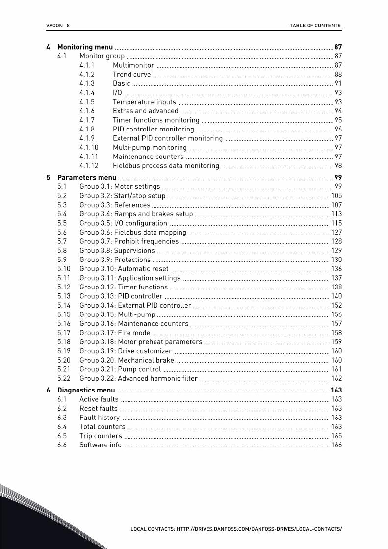
4 Monitoring menu 874.1 Monitor group 87
4.1.1 Multimonitor 874.1.2 Trend curve 884.1.3 Basic 914.1.4 I/O 934.1.5 Temperature inputs 934.1.6 Extras and advanced 944.1.7 Timer functions monitoring 954.1.8 PID controller monitoring 964.1.9 External PID controller monitoring 974.1.10 Multi-pump monitoring 974.1.11 Maintenance counters 974.1.12 Fieldbus process data monitoring 98
5 Parameters menu 995.1 Group 3.1: Motor settings 995.2 Group 3.2: Start/stop setup 1055.3 Group 3.3: References 1075.4 Group 3.4: Ramps and brakes setup 1135.5 Group 3.5: I/O configuration 1155.6 Group 3.6: Fieldbus data mapping 1275.7 Group 3.7: Prohibit frequencies 1285.8 Group 3.8: Supervisions 1295.9 Group 3.9: Protections 1305.10 Group 3.10: Automatic reset 1365.11 Group 3.11: Application settings 1375.12 Group 3.12: Timer functions 1385.13 Group 3.13: PID controller 1405.14 Group 3.14: External PID controller 1525.15 Group 3.15: Multi-pump 1565.16 Group 3.16: Maintenance counters 1575.17 Group 3.17: Fire mode 1585.18 Group 3.18: Motor preheat parameters 1595.19 Group 3.19: Drive customizer 1605.20 Group 3.20: Mechanical brake 1605.21 Group 3.21: Pump control 1615.22 Group 3.22: Advanced harmonic filter 162
6 Diagnostics menu 1636.1 Active faults 1636.2 Reset faults 1636.3 Fault history 1636.4 Total counters 1636.5 Trip counters 1656.6 Software info 166
VACON · 8 TABLE OF CONTENTS
LOCAL CONTACTS: HTTP://DRIVES.DANFOSS.COM/DANFOSS-DRIVES/LOCAL-CONTACTS/
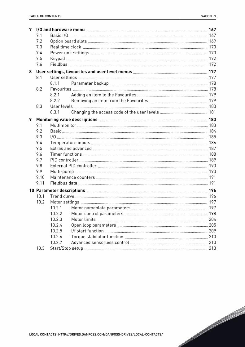
7 I/O and hardware menu 1677.1 Basic I/O 1677.2 Option board slots 1697.3 Real time clock 1707.4 Power unit settings 1707.5 Keypad 1727.6 Fieldbus 172
8 User settings, favourites and user level menus 1778.1 User settings 177
8.1.1 Parameter backup 1788.2 Favourites 178
8.2.1 Adding an item to the Favourites 1798.2.2 Removing an item from the Favourites 179
8.3 User levels 1808.3.1 Changing the access code of the user levels 181
9 Monitoring value descriptions 1839.1 Multimonitor 1839.2 Basic 1849.3 I/O 1859.4 Temperature inputs 1869.5 Extras and advanced 1879.6 Timer functions 1889.7 PID controller 1899.8 External PID controller 1909.9 Multi-pump 1909.10 Maintenance counters 1919.11 Fieldbus data 191
10 Parameter descriptions 19610.1 Trend curve 19610.2 Motor settings 197
10.2.1 Motor nameplate parameters 19710.2.2 Motor control parameters 19810.2.3 Motor limits 20410.2.4 Open loop parameters 20510.2.5 I/f start function 20910.2.6 Torque stabilator function 21010.2.7 Advanced sensorless control 210
10.3 Start/Stop setup 213
TABLE OF CONTENTS VACON · 9
LOCAL CONTACTS: HTTP://DRIVES.DANFOSS.COM/DANFOSS-DRIVES/LOCAL-CONTACTS/
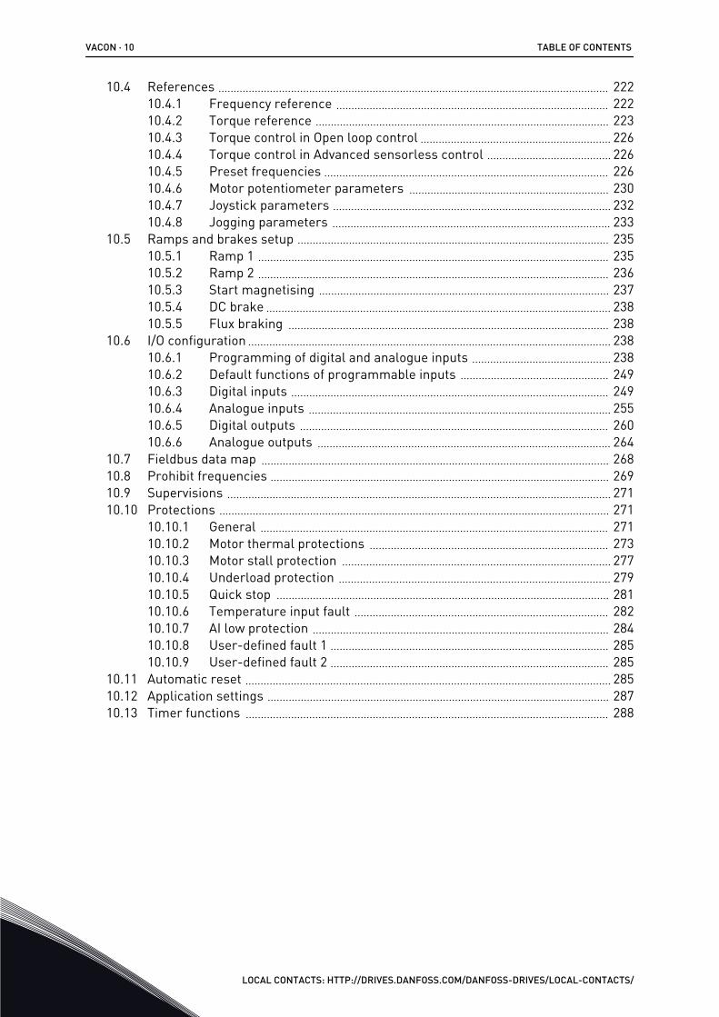
10.4 References 22210.4.1 Frequency reference 22210.4.2 Torque reference 22310.4.3 Torque control in Open loop control 22610.4.4 Torque control in Advanced sensorless control 22610.4.5 Preset frequencies 22610.4.6 Motor potentiometer parameters 23010.4.7 Joystick parameters 23210.4.8 Jogging parameters 233
10.5 Ramps and brakes setup 23510.5.1 Ramp 1 23510.5.2 Ramp 2 23610.5.3 Start magnetising 23710.5.4 DC brake 23810.5.5 Flux braking 238
10.6 I/O configuration 23810.6.1 Programming of digital and analogue inputs 23810.6.2 Default functions of programmable inputs 24910.6.3 Digital inputs 24910.6.4 Analogue inputs 25510.6.5 Digital outputs 26010.6.6 Analogue outputs 264
10.7 Fieldbus data map 26810.8 Prohibit frequencies 26910.9 Supervisions 27110.10 Protections 271
10.10.1 General 27110.10.2 Motor thermal protections 27310.10.3 Motor stall protection 27710.10.4 Underload protection 27910.10.5 Quick stop 28110.10.6 Temperature input fault 28210.10.7 AI low protection 28410.10.8 User-defined fault 1 28510.10.9 User-defined fault 2 285
10.11 Automatic reset 28510.12 Application settings 28710.13 Timer functions 288
VACON · 10 TABLE OF CONTENTS
LOCAL CONTACTS: HTTP://DRIVES.DANFOSS.COM/DANFOSS-DRIVES/LOCAL-CONTACTS/
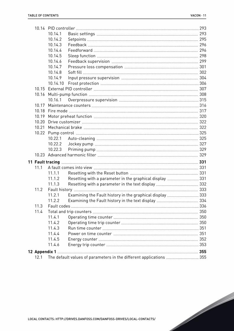
10.14 PID controller 29310.14.1 Basic settings 29310.14.2 Setpoints 29510.14.3 Feedback 29610.14.4 Feedforward 29610.14.5 Sleep function 29810.14.6 Feedback supervision 29910.14.7 Pressure loss compensation 30110.14.8 Soft fill 30210.14.9 Input pressure supervision 30410.14.10 Frost protection 306
10.15 External PID controller 30710.16 Multi-pump function 308
10.16.1 Overpressure supervision 31510.17 Maintenance counters 31610.18 Fire mode 31710.19 Motor preheat function 32010.20 Drive customizer 32210.21 Mechanical brake 32210.22 Pump control 325
10.22.1 Auto-cleaning 32510.22.2 Jockey pump 32710.22.3 Priming pump 329
10.23 Advanced harmonic filter 32911 Fault tracing 331
11.1 A fault comes into view 33111.1.1 Resetting with the Reset button 33111.1.2 Resetting with a parameter in the graphical display 33111.1.3 Resetting with a parameter in the text display 332
11.2 Fault history 33311.2.1 Examining the Fault history in the graphical display 33311.2.2 Examining the Fault history in the text display 334
11.3 Fault codes 33611.4 Total and trip counters 350
11.4.1 Operating time counter 35011.4.2 Operating time trip counter 35011.4.3 Run time counter 35111.4.4 Power on time counter 35111.4.5 Energy counter 35211.4.6 Energy trip counter 353
12 Appendix 1 35512.1 The default values of parameters in the different applications 355
TABLE OF CONTENTS VACON · 11
LOCAL CONTACTS: HTTP://DRIVES.DANFOSS.COM/DANFOSS-DRIVES/LOCAL-CONTACTS/
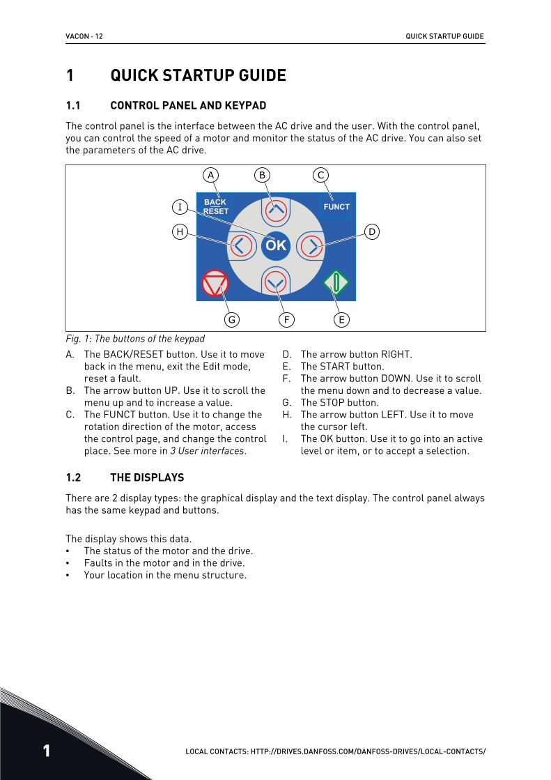
1 QUICK STARTUP GUIDE1.1 CONTROL PANEL AND KEYPAD
The control panel is the interface between the AC drive and the user. With the control panel,you can control the speed of a motor and monitor the status of the AC drive. You can also setthe parameters of the AC drive.
A B C
I
H D
G F E
Fig. 1: The buttons of the keypadA. The BACK/RESET button. Use it to move
back in the menu, exit the Edit mode,reset a fault.
B. The arrow button UP. Use it to scroll themenu up and to increase a value.
C. The FUNCT button. Use it to change therotation direction of the motor, accessthe control page, and change the controlplace. See more in 3 User interfaces.
D. The arrow button RIGHT.E. The START button.F. The arrow button DOWN. Use it to scroll
the menu down and to decrease a value.G. The STOP button.H. The arrow button LEFT. Use it to move
the cursor left.I. The OK button. Use it to go into an active
level or item, or to accept a selection.
1.2 THE DISPLAYS
There are 2 display types: the graphical display and the text display. The control panel alwayshas the same keypad and buttons.
The display shows this data.• The status of the motor and the drive.• Faults in the motor and in the drive.• Your location in the menu structure.
VACON · 12 QUICK STARTUP GUIDE
1 LOCAL CONTACTS: HTTP://DRIVES.DANFOSS.COM/DANFOSS-DRIVES/LOCAL-CONTACTS/
STOP READY I/O
Main Menu
A B C D E
F
H
GQuick Setup( 17 )Monitor( 5 )
Parameters( 12 )
M1ID:
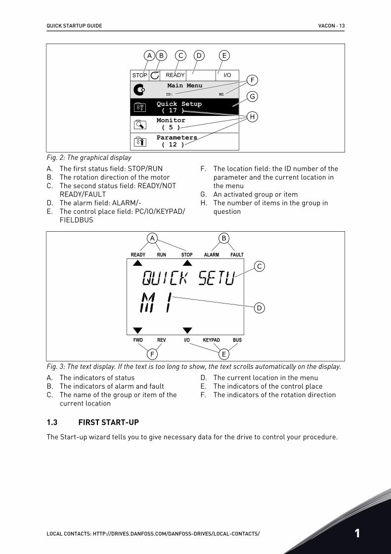
Fig. 2: The graphical displayA. The first status field: STOP/RUNB. The rotation direction of the motorC. The second status field: READY/NOT
READY/FAULTD. The alarm field: ALARM/-E. The control place field: PC/IO/KEYPAD/
FIELDBUS
F. The location field: the ID number of theparameter and the current location inthe menu
G. An activated group or itemH. The number of items in the group in
question
A B
F
C
D
E
Fig. 3: The text display. If the text is too long to show, the text scrolls automatically on the display.A. The indicators of statusB. The indicators of alarm and faultC. The name of the group or item of the
current location
D. The current location in the menuE. The indicators of the control placeF. The indicators of the rotation direction
1.3 FIRST START-UP
The Start-up wizard tells you to give necessary data for the drive to control your procedure.
QUICK STARTUP GUIDE VACON · 13
LOCAL CONTACTS: HTTP://DRIVES.DANFOSS.COM/DANFOSS-DRIVES/LOCAL-CONTACTS/ 1
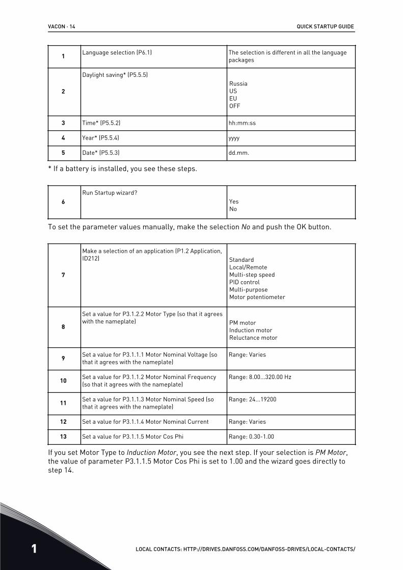
1 Language selection (P6.1) The selection is different in all the languagepackages
2
Daylight saving* (P5.5.5)RussiaUSEUOFF
3 Time* (P5.5.2) hh:mm:ss
4 Year* (P5.5.4) yyyy
5 Date* (P5.5.3) dd.mm.
* If a battery is installed, you see these steps.
6Run Startup wizard?
YesNo
To set the parameter values manually, make the selection No and push the OK button.
7
Make a selection of an application (P1.2 Application,ID212) Standard
Local/RemoteMulti-step speedPID controlMulti-purposeMotor potentiometer
8
Set a value for P3.1.2.2 Motor Type (so that it agreeswith the nameplate) PM motor
Induction motorReluctance motor
9 Set a value for P3.1.1.1 Motor Nominal Voltage (sothat it agrees with the nameplate)
Range: Varies
10 Set a value for P3.1.1.2 Motor Nominal Frequency(so that it agrees with the nameplate)
Range: 8.00...320.00 Hz
11 Set a value for P3.1.1.3 Motor Nominal Speed (sothat it agrees with the nameplate)
Range: 24...19200
12 Set a value for P3.1.1.4 Motor Nominal Current Range: Varies
13 Set a value for P3.1.1.5 Motor Cos Phi Range: 0.30-1.00
If you set Motor Type to Induction Motor, you see the next step. If your selection is PM Motor,the value of parameter P3.1.1.5 Motor Cos Phi is set to 1.00 and the wizard goes directly tostep 14.
VACON · 14 QUICK STARTUP GUIDE
1 LOCAL CONTACTS: HTTP://DRIVES.DANFOSS.COM/DANFOSS-DRIVES/LOCAL-CONTACTS/
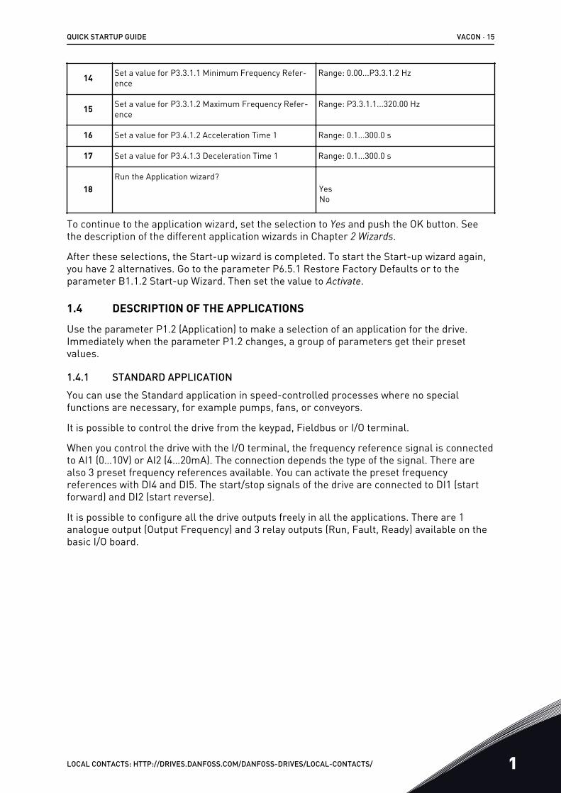
14 Set a value for P3.3.1.1 Minimum Frequency Refer-ence
Range: 0.00...P3.3.1.2 Hz
15 Set a value for P3.3.1.2 Maximum Frequency Refer-ence
Range: P3.3.1.1...320.00 Hz
16 Set a value for P3.4.1.2 Acceleration Time 1 Range: 0.1...300.0 s
17 Set a value for P3.4.1.3 Deceleration Time 1 Range: 0.1...300.0 s
18Run the Application wizard?
YesNo
To continue to the application wizard, set the selection to Yes and push the OK button. Seethe description of the different application wizards in Chapter 2 Wizards.
After these selections, the Start-up wizard is completed. To start the Start-up wizard again,you have 2 alternatives. Go to the parameter P6.5.1 Restore Factory Defaults or to theparameter B1.1.2 Start-up Wizard. Then set the value to Activate.
1.4 DESCRIPTION OF THE APPLICATIONS
Use the parameter P1.2 (Application) to make a selection of an application for the drive.Immediately when the parameter P1.2 changes, a group of parameters get their presetvalues.
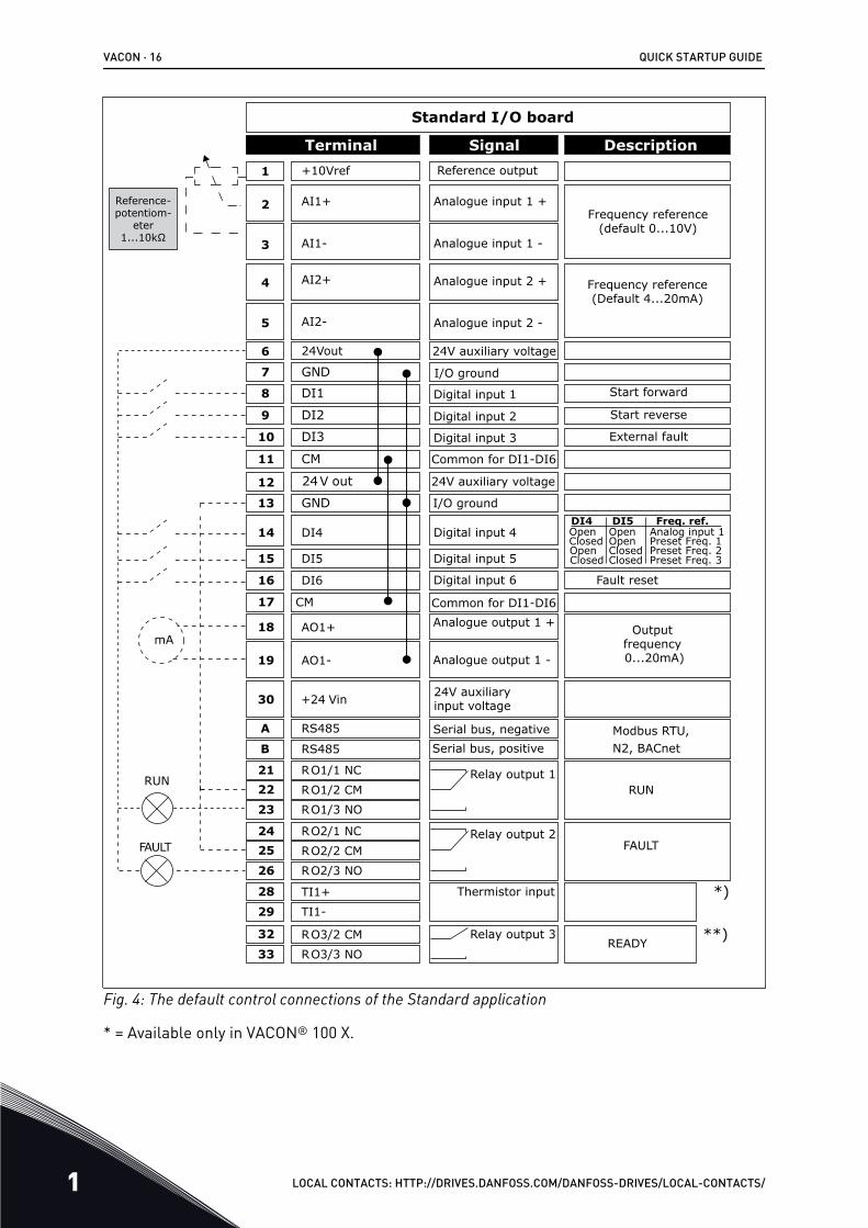
1.4.1 STANDARD APPLICATIONYou can use the Standard application in speed-controlled processes where no specialfunctions are necessary, for example pumps, fans, or conveyors.
It is possible to control the drive from the keypad, Fieldbus or I/O terminal.
When you control the drive with the I/O terminal, the frequency reference signal is connectedto AI1 (0…10V) or AI2 (4…20mA). The connection depends the type of the signal. There arealso 3 preset frequency references available. You can activate the preset frequencyreferences with DI4 and DI5. The start/stop signals of the drive are connected to DI1 (startforward) and DI2 (start reverse).
It is possible to configure all the drive outputs freely in all the applications. There are 1analogue output (Output Frequency) and 3 relay outputs (Run, Fault, Ready) available on thebasic I/O board.
QUICK STARTUP GUIDE VACON · 15
LOCAL CONTACTS: HTTP://DRIVES.DANFOSS.COM/DANFOSS-DRIVES/LOCAL-CONTACTS/ 1
DI4 DI5
**)
*)
Modbus RTU, N2, BACnet
1
6
2
3
4
5
18
19
30
12
7
13
8
9
10
14
15
16
212223
11
17
A
B
2425
26
32
33
28
29
mA
FAULT
RUNRUN
AO1-
+24 Vin
24V out
GND
GND
DI1
DI2
DI3
DI4
DI5
DI6
RO1/1 NC
RO1/2 CMRO1/3 NO
CM
CM
RS485
RS485
RO2/1 NC
RO2/2 CM
RO2/3 NO
RO3/2 CM
RO3/3 NO
Standard I/O board
Terminal Signal Description+10Vref
AI1+
AI1-
AI2+
AI2-
24Vout
Reference output
Analogue input 1 +
Analogue input 1 -
Analogue input 2 +
Analogue input 2 -
24V auxiliary voltage
I/O ground
Digital input 1
Digital input 2
Digital input 3
Digital input 4
Digital input 5
Digital input 6
Common for DI1-DI6
Common for DI1-DI6
24V auxiliary voltage
I/O ground
Analogue output 1 +
Analogue output 1 -
24V auxiliaryinput voltage
Output frequency 0...20mA)
READY
Serial bus, negativeSerial bus, positive
Relay output 1
Relay output 2
Relay output 3
FAULT
Fault reset
AO1+
Frequency reference (default 0...10V)
Frequency reference (Default 4...20mA)
Start forward
Start reverse
External fault
Freq. ref.OpenClosedOpenClosed
OpenOpenClosedClosed
Analog input 1Preset Freq. 1Preset Freq. 2Preset Freq. 3
Reference-potentiom-
eter 1...10kΩ
TI1+
TI1-
Thermistor input
Fig. 4: The default control connections of the Standard application
* = Available only in VACON® 100 X.
VACON · 16 QUICK STARTUP GUIDE
1 LOCAL CONTACTS: HTTP://DRIVES.DANFOSS.COM/DANFOSS-DRIVES/LOCAL-CONTACTS/

** = For the DIP switch configurations in VACON® 100 X, see the VACON® 100 X Installationmanual.
AB
C
Fig. 5: The DIP switchA. Digital input DIP switchB. Floating
C. Connected to GND (Default)
Table 2: M1.1 Wizards
Index Parameter Min Max Unit Default ID Description
1.1.1 Startup wizard 0 1 0 1170
0 = Do not activate1 = Activate
The selection Activatestarts the Start-up wiz-ard (see Chapter 1.3 First start-up.
1.1.3 Multi-pump Wizard 0 1 0 1671
The selection Activatestarts the Multi-pumpwizard (see Chapter2.7 Multi-pump wizard).
1.1.4 Fire mode Wizard 0 1 0 1672
The selection Activatestarts the Fire modewizard (see Chapter2.8 Fire mode wizard).
QUICK STARTUP GUIDE VACON · 17
LOCAL CONTACTS: HTTP://DRIVES.DANFOSS.COM/DANFOSS-DRIVES/LOCAL-CONTACTS/ 1

Table 3: M1 Quick Setup
Index Parameter Min Max Unit Default ID Description
1.2 Application 0 5 0 212
0 = Standard1 = Local/Remote2 = Multi-Step Speed3 = PID Control4 = Multi-Purpose5 = Motor Potentiome-ter
1.3 Minimum FrequencyReference 0.00 P1.4 Hz 0.0 101
1.4 Maximum FrequencyReference P1.3 320.0 Hz 50.0 /
60.0 102
1.5 Acceleration Time 1 0.1 300.0 s 5.0 103
1.6 Deceleration Time 1 0.1 300.0 s 5.0 104
1.7 Motor Current Limit IH*0.1 IS A Varies 107
1.8 Motor Type 0 2 0 6500 = Induction Motor1 = Permanent MagnetMotor2 = Reluctance Motor
1.9 Motor Nominal Volt-age Varies Varies V Varies 110
Find this value Un onthe nameplate of themotor.
NOTE!Find out if the motorconnection is Delta orStar.
1.10 Motor Nominal Fre-quency 8.0 320.0 Hz 50 / 60 111
Find this value fn onthe nameplate of themotor.
1.11 Motor NominalSpeed 24 19200 Rpm Varies 112
Find this value nn onthe nameplate of themotor.
1.12 Motor Nominal Cur-rent IH * 0.1 IH * 2 A Varies 113
Find this value In onthe nameplate of themotor.
1.13 Motor Cos Phi(Power Factor) 0.30 1.00 Varies 120
Find this value on thenameplate of themotor.
VACON · 18 QUICK STARTUP GUIDE
1 LOCAL CONTACTS: HTTP://DRIVES.DANFOSS.COM/DANFOSS-DRIVES/LOCAL-CONTACTS/

Table 3: M1 Quick Setup
Index Parameter Min Max Unit Default ID Description
1.14 Energy Optimization 0 1 0 666 0 = Disabled1 = Enabled
1.15 Identification 0 2 0 631 0 = No action1 = At standstill2 = With rotation
1.16 Start Function 0 1 0 505 0 = Ramping1 = Flying Start
1.17 Stop Function 0 1 0 506 0 = Coasting1 = Ramping
1.18 Automatic Reset 0 1 0 731 0 = Disabled1 = Enabled
1.19 Response to ExternalFault 0 3 2 701
0 = No action1 = Alarm2 = Fault (Stop accord-ing to stop mode)3 = Fault (Stop bycoasting)
1.20 Response to AI LowFault 0 5 0 700
0 = No action1 = Alarm2 = Alarm+preset faultfrequency (P3.9.1.13)3 = Alarm + previousfrequency4 = Fault (Stop accord-ing to stop mode)5 = Fault (Stop bycoasting)
1.21 Remote ControlPlace 0 1 0 172 0 = I/O control
1 = Fieldbus control
QUICK STARTUP GUIDE VACON · 19
LOCAL CONTACTS: HTTP://DRIVES.DANFOSS.COM/DANFOSS-DRIVES/LOCAL-CONTACTS/ 1

Table 3: M1 Quick Setup
Index Parameter Min Max Unit Default ID Description
1.22 I/O Control Refer-ence A Selection 0 9 5 117
0 = Preset Frequency 01 = Keypad Reference2 = Fieldbus3 = AI14 = AI25 = AI1+AI26 = PID Reference7 = Motor Potentiome-ter8 = Joystick Reference9 = Jogging Reference10 = Block Out.111 = Block Out.212 = Block Out.313 = Block Out.414 = Block Out.515 = Block Out.616 = Block Out.717 = Block Out.818 = Block Out.919 = Block Out.10
1.23 Keypad Control Ref-erence Selection 0 9 1 121 See P1.22.
1.24 Fieldbus ControlReference Selection 0 9 2 122 See P1.22.
1.25 AI1 Signal Range 0 1 0 379 0= 0..10V / 0..20mA1= 2..10V / 4..20mA
1.26 AI2 Signal Range 0 1 1 390 0= 0..10V / 0..20mA1= 2..10V / 4..20mA
1.27 RO1 Function 0 61 2 11001 See P3.5.3.2.1
1.28 RO2 Function 0 56 3 11004 See P3.5.3.2.1
1.29 RO3 Function 0 56 1 11007 See P3.5.3.2.1
1.30 AO1 Function 0 31 2 10050 See P3.5.4.1.1
VACON · 20 QUICK STARTUP GUIDE
1 LOCAL CONTACTS: HTTP://DRIVES.DANFOSS.COM/DANFOSS-DRIVES/LOCAL-CONTACTS/
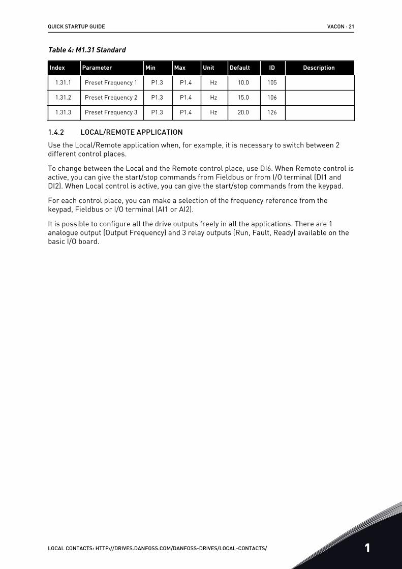
Table 4: M1.31 Standard
Index Parameter Min Max Unit Default ID Description
1.31.1 Preset Frequency 1 P1.3 P1.4 Hz 10.0 105
1.31.2 Preset Frequency 2 P1.3 P1.4 Hz 15.0 106
1.31.3 Preset Frequency 3 P1.3 P1.4 Hz 20.0 126
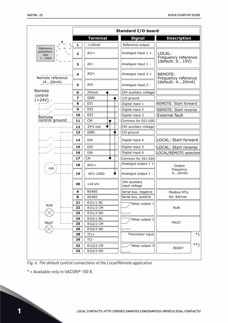
1.4.2 LOCAL/REMOTE APPLICATIONUse the Local/Remote application when, for example, it is necessary to switch between 2different control places.
To change between the Local and the Remote control place, use DI6. When Remote control isactive, you can give the start/stop commands from Fieldbus or from I/O terminal (DI1 andDI2). When Local control is active, you can give the start/stop commands from the keypad.
For each control place, you can make a selection of the frequency reference from thekeypad, Fieldbus or I/O terminal (AI1 or AI2).
It is possible to configure all the drive outputs freely in all the applications. There are 1analogue output (Output Frequency) and 3 relay outputs (Run, Fault, Ready) available on thebasic I/O board.
QUICK STARTUP GUIDE VACON · 21
LOCAL CONTACTS: HTTP://DRIVES.DANFOSS.COM/DANFOSS-DRIVES/LOCAL-CONTACTS/ 1
1
6
2
3
4
5
18
19
30
12
7
13
8
9
10
14
15
16
212223
11
17
A
B
2425
26
32
33
Modbus RTU, N2, BACnet
28
29*)
**)
mA
FAULT
RUNRUN
AO1-/GND
+24 Vin
24V out
GND
GND
DI1
DI2
DI3
DI4
DI5
DI6
RO1/1 NC
RO1/2 CMRO1/3 NO
CM
CM
RS485
RS485
RO2/1 NC
RO2/2 CM
RO2/3 NO
RO3/2 CM
RO3/3 NO
Standard I/O board
Terminal Signal Description+10Vref
AI1+
AI1-
AI2+
AI2-
24Vout
Reference output
Analogue input 1 +
Analogue input 1 -
Analogue input 2 +
Analogue input 2 -
24V auxiliary voltage
I/O ground
Digital input 1
Digital input 2
Digital input 3
Digital input 4
Digital input 5
Digital input 6
Common for DI1-DI6
Common for DI1-DI6
24V auxiliary voltage
I/O ground
Analogue output 1 +
Analogue output 1 -
24V auxiliaryinput voltage
Output frequency 0...20mA)
READY
Serial bus, negativeSerial bus, positive
Relay output 1
Relay output 2
Relay output 3
FAULT
AO1+
Reference potentiom-
eter 1...10kΩ
Remote reference (4...20mA)
Remote control (+24V)
Remote control ground
REMOTE: Frequency reference (default: 4...20mA)
LOCAL: Frequency reference (default: 0...10V)
REMOTE: Start forward
REMOTE: Start reverseExternal fault
LOCAL: Start forward
LOCAL: Start reverseLOCAL/REMOTE selection
TI1+
TI1-
Thermistor input
Fig. 6: The default control connections of the Local/Remote application
* = Available only in VACON® 100 X.
VACON · 22 QUICK STARTUP GUIDE
1 LOCAL CONTACTS: HTTP://DRIVES.DANFOSS.COM/DANFOSS-DRIVES/LOCAL-CONTACTS/

** = For the DIP switch configurations in VACON® 100 X, see the VACON® 100 X Installationmanual.
AB
C
Fig. 7: The DIP switchA. Digital input DIP switchB. Floating
C. Connected to GND (Default)
Table 5: M1.1 Wizards
Index Parameter Min Max Unit Default ID Description
1.1.1 Startup wizard 0 1 0 1170
0 = Do not activate1 = Activate
The selection Activatestarts the Start-up wiz-ard (see Chapter 1.3 First start-up.
1.1.3 Multi-pump Wizard 0 1 0 1671
The selection Activatestarts the Multi-pumpwizard (see Chapter2.7 Multi-pump wizard).
1.1.4 Fire mode Wizard 0 1 0 1672
The selection Activatestarts the Fire modewizard (see Chapter2.8 Fire mode wizard).
QUICK STARTUP GUIDE VACON · 23
LOCAL CONTACTS: HTTP://DRIVES.DANFOSS.COM/DANFOSS-DRIVES/LOCAL-CONTACTS/ 1

Table 6: M1 Quick Setup
Index Parameter Min Max Unit Default ID Description
1.2 Application 0 5 1 212
0 = Standard1 = Local/Remote2 = Multi-Step Speed3 = PID Control4 = Multi-Purpose5 = Motor Potentiome-ter
1.3 Minimum FrequencyReference 0.00 P1.4 Hz 0.0 101
1.4 Maximum FrequencyReference P1.3 320.0 Hz 50.0 /
60.0 102
1.5 Acceleration Time 1 0.1 300.0 s 5.0 103
1.6 Deceleration Time 1 0.1 300.0 s 5.0 104
1.7 Motor Current Limit IH*0.1 IS A Varies 107
1.8 Motor Type 0 2 0 6500 = Induction Motor1 = Permanent MagnetMotor2 = Reluctance Motor
1.9 Motor Nominal Volt-age Varies Varies V Varies 110
Find this value Un onthe nameplate of themotor.
NOTE!Find out if the motorconnection is Delta orStar.
1.10 Motor Nominal Fre-quency 8.0 320.0 Hz 50 / 60 111
Find this value fn onthe nameplate of themotor.
1.11 Motor NominalSpeed 24 19200 Rpm Varies 112
Find this value nn onthe nameplate of themotor.
1.12 Motor Nominal Cur-rent IH * 0.1 IH * 2 A Varies 113
Find this value In onthe nameplate of themotor.
1.13 Motor Cos Phi(Power Factor) 0.30 1.00 Varies 120
Find this value on thenameplate of themotor.
VACON · 24 QUICK STARTUP GUIDE
1 LOCAL CONTACTS: HTTP://DRIVES.DANFOSS.COM/DANFOSS-DRIVES/LOCAL-CONTACTS/
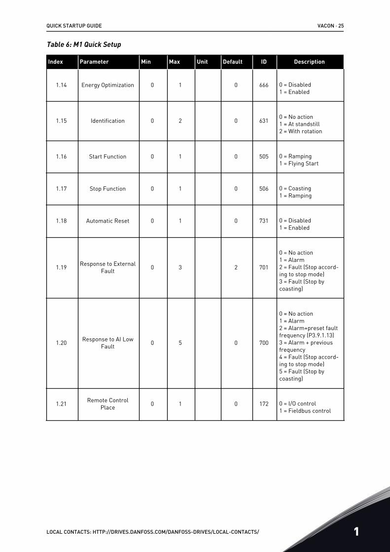
Table 6: M1 Quick Setup
Index Parameter Min Max Unit Default ID Description
1.14 Energy Optimization 0 1 0 666 0 = Disabled1 = Enabled
1.15 Identification 0 2 0 631 0 = No action1 = At standstill2 = With rotation
1.16 Start Function 0 1 0 505 0 = Ramping1 = Flying Start
1.17 Stop Function 0 1 0 506 0 = Coasting1 = Ramping
1.18 Automatic Reset 0 1 0 731 0 = Disabled1 = Enabled
1.19 Response to ExternalFault 0 3 2 701
0 = No action1 = Alarm2 = Fault (Stop accord-ing to stop mode)3 = Fault (Stop bycoasting)
1.20 Response to AI LowFault 0 5 0 700
0 = No action1 = Alarm2 = Alarm+preset faultfrequency (P3.9.1.13)3 = Alarm + previousfrequency4 = Fault (Stop accord-ing to stop mode)5 = Fault (Stop bycoasting)
1.21 Remote ControlPlace 0 1 0 172 0 = I/O control
1 = Fieldbus control
QUICK STARTUP GUIDE VACON · 25
LOCAL CONTACTS: HTTP://DRIVES.DANFOSS.COM/DANFOSS-DRIVES/LOCAL-CONTACTS/ 1

Table 6: M1 Quick Setup
Index Parameter Min Max Unit Default ID Description
1.22 I/O Control Refer-ence A Selection 0 9 3 117
0 = Preset Frequency 01 = Keypad Reference2 = Fieldbus3 = AI14 = AI25 = AI1+AI26 = PID Reference7 = Motor Potentiome-ter8 = Joystick Reference9 = Jogging Reference10 = Block Out.111 = Block Out.212 = Block Out.313 = Block Out.414 = Block Out.515 = Block Out.616 = Block Out.717 = Block Out.818 = Block Out.919 = Block Out.10
1.23 Keypad Control Ref-erence Selection 0 9 1 121 See P1.22.
1.24 Fieldbus ControlReference Selection 0 9 2 122 See P1.22.
1.25 AI1 Signal Range 0 1 0 379 0= 0..10V / 0..20mA1= 2..10V / 4..20mA
1.26 AI2 Signal Range 0 1 1 390 0= 0..10V / 0..20mA1= 2..10V / 4..20mA
1.27 RO1 Function 0 61 2 11001 See P3.5.3.2.1
1.28 RO2 Function 0 56 3 11004 See P3.5.3.2.1
1.29 RO3 Function 0 56 1 11007 See P3.5.3.2.1
1.30 AO1 Function 0 31 2 10050 See P3.5.4.1.1
VACON · 26 QUICK STARTUP GUIDE
1 LOCAL CONTACTS: HTTP://DRIVES.DANFOSS.COM/DANFOSS-DRIVES/LOCAL-CONTACTS/
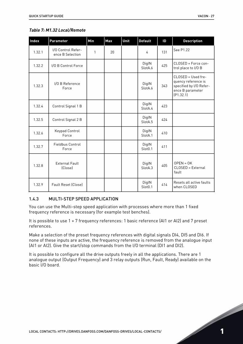
Table 7: M1.32 Local/Remote
Index Parameter Min Max Unit Default ID Description
1.32.1 I/O Control Refer-ence B Selection 1 20 4 131 See P1.22
1.32.2 I/O B Control Force DigINSlotA.6 425 CLOSED = Force con-
trol place to I/O B
1.32.3 I/O B ReferenceForce
DigINSlotA.6 343
CLOSED = Used fre-quency reference isspecified by I/O Refer-ence B parameter(P1.32.1)
1.32.4 Control Signal 1 B DigINSlotA.4 423
1.32.5 Control Signal 2 B DigINSlotA.5 424
1.32.6 Keypad ControlForce
DigINSlotA.1 410
1.32.7 Fieldbus ControlForce
DigINSlot0.1 411
1.32.8 External Fault(Close)
DigINSlotA.3 405 OPEN = OK
CLOSED = Externalfault
1.32.9 Fault Reset (Close) DigINSlot0.1 414 Resets all active faults
when CLOSED
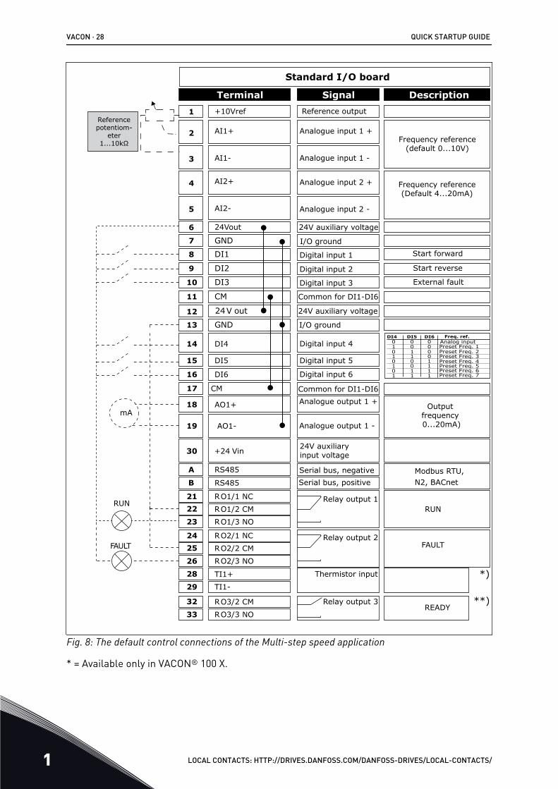
1.4.3 MULTI-STEP SPEED APPLICATIONYou can use the Multi-step speed application with processes where more than 1 fixedfrequency reference is necessary (for example test benches).
It is possible to use 1 + 7 frequency references: 1 basic reference (AI1 or AI2) and 7 presetreferences.
Make a selection of the preset frequency references with digital signals DI4, DI5 and DI6. Ifnone of these inputs are active, the frequency reference is removed from the analogue input(AI1 or AI2). Give the start/stop commands from the I/O terminal (DI1 and DI2).
It is possible to configure all the drive outputs freely in all the applications. There are 1analogue output (Output Frequency) and 3 relay outputs (Run, Fault, Ready) available on thebasic I/O board.
QUICK STARTUP GUIDE VACON · 27
LOCAL CONTACTS: HTTP://DRIVES.DANFOSS.COM/DANFOSS-DRIVES/LOCAL-CONTACTS/ 1
DI4 DI5
1
DI60 0 0
0 0
10
01
1
11
11
1
00
0
001
1
1
1
6
2
3
4
5
18
19
30
12
7
13
8
9
10
14
15
16
212223
11
17
A
B
2425
26
32
33
Modbus RTU, N2, BACnet
28
29*)
**)
mA
FAULT
RUNRUN
AO1-
+24 Vin
24V out
GND
GND
DI1
DI2
DI3
DI4
DI5
DI6
RO1/1 NC
RO1/2 CMRO1/3 NO
CM
CM
RS485
RS485
RO2/1 NC
RO2/2 CM
RO2/3 NO
RO3/2 CM
RO3/3 NO
Standard I/O board
Terminal Signal Description+10Vref
AI1+
AI1-
AI2+
AI2-
24Vout
Reference output
Analogue input 1 +
Analogue input 1 -
Analogue input 2 +
Analogue input 2 -
24V auxiliary voltage
I/O ground
Digital input 1
Digital input 2
Digital input 3
Digital input 4
Digital input 5
Digital input 6
Common for DI1-DI6
Common for DI1-DI6
24V auxiliary voltage
I/O ground
Analogue output 1 +
Analogue output 1 -
24V auxiliaryinput voltage
Output frequency 0...20mA)
READY
Serial bus, negativeSerial bus, positive
Relay output 1
Relay output 2
Relay output 3
FAULT
AO1+
Frequency reference (default 0...10V)
Frequency reference (Default 4...20mA)
Start forward
Start reverse
External fault
Analog inputPreset Freq. 1Preset Freq. 2Preset Freq. 3Preset Freq. 4Preset Freq. 5Preset Freq. 6Preset Freq. 7
Freq. ref.
TI1+
TI1-
Thermistor input
Reference potentiom-
eter 1...10kΩ
Fig. 8: The default control connections of the Multi-step speed application
* = Available only in VACON® 100 X.
VACON · 28 QUICK STARTUP GUIDE
1 LOCAL CONTACTS: HTTP://DRIVES.DANFOSS.COM/DANFOSS-DRIVES/LOCAL-CONTACTS/
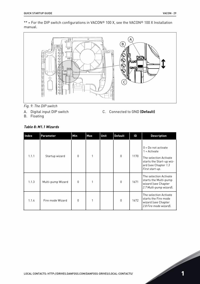
** = For the DIP switch configurations in VACON® 100 X, see the VACON® 100 X Installationmanual.
AB
C
Fig. 9: The DIP switchA. Digital input DIP switchB. Floating
C. Connected to GND (Default)
Table 8: M1.1 Wizards
Index Parameter Min Max Unit Default ID Description
1.1.1 Startup wizard 0 1 0 1170
0 = Do not activate1 = Activate
The selection Activatestarts the Start-up wiz-ard (see Chapter 1.3 First start-up.
1.1.3 Multi-pump Wizard 0 1 0 1671
The selection Activatestarts the Multi-pumpwizard (see Chapter2.7 Multi-pump wizard).
1.1.4 Fire mode Wizard 0 1 0 1672
The selection Activatestarts the Fire modewizard (see Chapter2.8 Fire mode wizard).
QUICK STARTUP GUIDE VACON · 29
LOCAL CONTACTS: HTTP://DRIVES.DANFOSS.COM/DANFOSS-DRIVES/LOCAL-CONTACTS/ 1
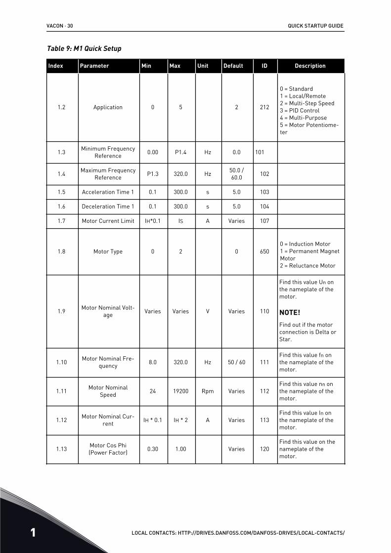
Table 9: M1 Quick Setup
Index Parameter Min Max Unit Default ID Description
1.2 Application 0 5 2 212
0 = Standard1 = Local/Remote2 = Multi-Step Speed3 = PID Control4 = Multi-Purpose5 = Motor Potentiome-ter
1.3 Minimum FrequencyReference 0.00 P1.4 Hz 0.0 101
1.4 Maximum FrequencyReference P1.3 320.0 Hz 50.0 /
60.0 102
1.5 Acceleration Time 1 0.1 300.0 s 5.0 103
1.6 Deceleration Time 1 0.1 300.0 s 5.0 104
1.7 Motor Current Limit IH*0.1 IS A Varies 107
1.8 Motor Type 0 2 0 6500 = Induction Motor1 = Permanent MagnetMotor2 = Reluctance Motor
1.9 Motor Nominal Volt-age Varies Varies V Varies 110
Find this value Un onthe nameplate of themotor.
NOTE!Find out if the motorconnection is Delta orStar.
1.10 Motor Nominal Fre-quency 8.0 320.0 Hz 50 / 60 111
Find this value fn onthe nameplate of themotor.
1.11 Motor NominalSpeed 24 19200 Rpm Varies 112
Find this value nn onthe nameplate of themotor.
1.12 Motor Nominal Cur-rent IH * 0.1 IH * 2 A Varies 113
Find this value In onthe nameplate of themotor.
1.13 Motor Cos Phi(Power Factor) 0.30 1.00 Varies 120
Find this value on thenameplate of themotor.
VACON · 30 QUICK STARTUP GUIDE
1 LOCAL CONTACTS: HTTP://DRIVES.DANFOSS.COM/DANFOSS-DRIVES/LOCAL-CONTACTS/

Table 9: M1 Quick Setup
Index Parameter Min Max Unit Default ID Description
1.14 Energy Optimization 0 1 0 666 0 = Disabled1 = Enabled
1.15 Identification 0 2 0 631 0 = No action1 = At standstill2 = With rotation
1.16 Start Function 0 1 0 505 0 = Ramping1 = Flying Start
1.17 Stop Function 0 1 0 506 0 = Coasting1 = Ramping
1.18 Automatic Reset 0 1 0 731 0 = Disabled1 = Enabled
1.19 Response to ExternalFault 0 3 2 701
0 = No action1 = Alarm2 = Fault (Stop accord-ing to stop mode)3 = Fault (Stop bycoasting)
1.20 Response to AI LowFault 0 5 0 700
0 = No action1 = Alarm2 = Alarm+preset faultfrequency (P3.9.1.13)3 = Alarm + previousfrequency4 = Fault (Stop accord-ing to stop mode)5 = Fault (Stop bycoasting)
1.21 Remote ControlPlace 0 1 0 172 0 = I/O control
1 = Fieldbus control
QUICK STARTUP GUIDE VACON · 31
LOCAL CONTACTS: HTTP://DRIVES.DANFOSS.COM/DANFOSS-DRIVES/LOCAL-CONTACTS/ 1
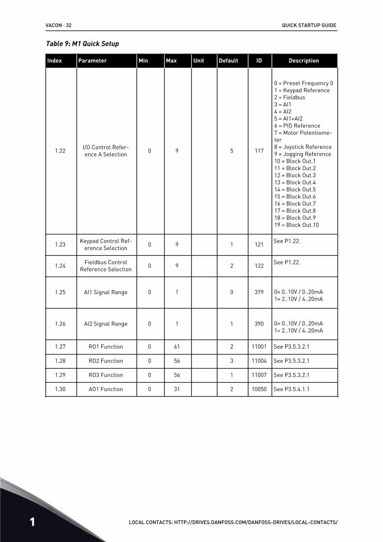
Table 9: M1 Quick Setup
Index Parameter Min Max Unit Default ID Description
1.22 I/O Control Refer-ence A Selection 0 9 5 117
0 = Preset Frequency 01 = Keypad Reference2 = Fieldbus3 = AI14 = AI25 = AI1+AI26 = PID Reference7 = Motor Potentiome-ter8 = Joystick Reference9 = Jogging Reference10 = Block Out.111 = Block Out.212 = Block Out.313 = Block Out.414 = Block Out.515 = Block Out.616 = Block Out.717 = Block Out.818 = Block Out.919 = Block Out.10
1.23 Keypad Control Ref-erence Selection 0 9 1 121 See P1.22.
1.24 Fieldbus ControlReference Selection 0 9 2 122 See P1.22.
1.25 AI1 Signal Range 0 1 0 379 0= 0..10V / 0..20mA1= 2..10V / 4..20mA
1.26 AI2 Signal Range 0 1 1 390 0= 0..10V / 0..20mA1= 2..10V / 4..20mA
1.27 RO1 Function 0 61 2 11001 See P3.5.3.2.1
1.28 RO2 Function 0 56 3 11004 See P3.5.3.2.1
1.29 RO3 Function 0 56 1 11007 See P3.5.3.2.1
1.30 AO1 Function 0 31 2 10050 See P3.5.4.1.1
VACON · 32 QUICK STARTUP GUIDE
1 LOCAL CONTACTS: HTTP://DRIVES.DANFOSS.COM/DANFOSS-DRIVES/LOCAL-CONTACTS/
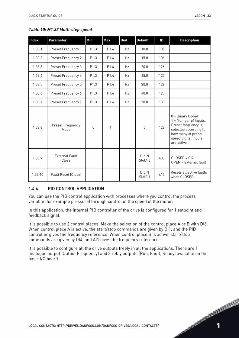
Table 10: M1.33 Multi-step speed
Index Parameter Min Max Unit Default ID Description
1.33.1 Preset Frequency 1 P1.3 P1.4 Hz 10.0 105
1.33.2 Preset Frequency 2 P1.3 P1.4 Hz 15.0 106
1.33.3 Preset Frequency 3 P1.3 P1.4 Hz 20.0 126
1.33.4 Preset Frequency 4 P1.3 P1.4 Hz 25.0 127
1.33.5 Preset Frequency 5 P1.3 P1.4 Hz 30.0 128
1.33.6 Preset Frequency 6 P1.3 P1.4 Hz 40.0 129
1.33.7 Preset Frequency 7 P1.3 P1.4 Hz 50.0 130
1.33.8 Preset FrequencyMode 0 1 0 128
0 = Binary Coded1 = Number of inputs.Preset frequency isselected according tohow many of presetspeed digital inputsare active.
1.33.9 External Fault(Close)
DigINSlotA.3 405 CLOSED = OK
OPEN = External fault
1.33.10 Fault Reset (Close) DigINSlot0.1 414 Resets all active faults
when CLOSED
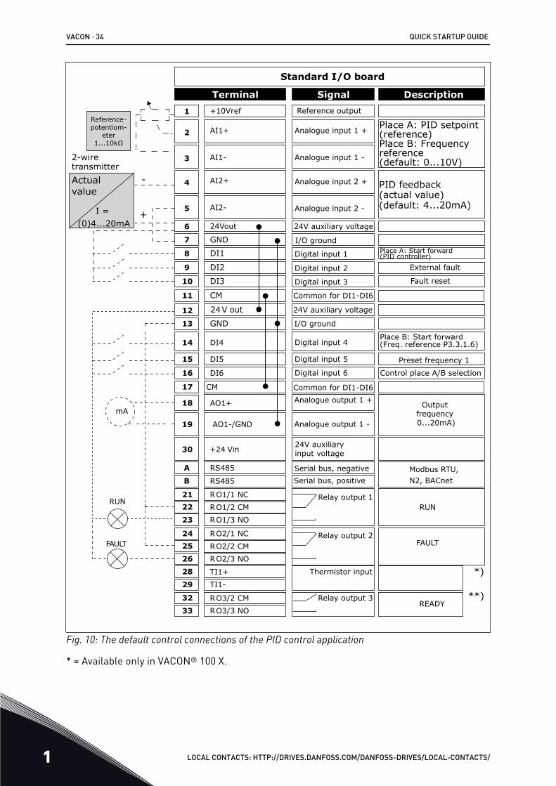
1.4.4 PID CONTROL APPLICATIONYou can use the PID control application with processes where you control the processvariable (for example pressure) through control of the speed of the motor.
In this application, the internal PID controller of the drive is configured for 1 setpoint and 1feedback signal.
It is possible to use 2 control places. Make the selection of the control place A or B with DI6.When control place A is active, the start/stop commands are given by DI1, and the PIDcontroller gives the frequency reference. When control place B is active, start/stopcommands are given by DI4, and AI1 gives the frequency reference.
It is possible to configure all the drive outputs freely in all the applications. There are 1analogue output (Output Frequency) and 3 relay outputs (Run, Fault, Ready) available on thebasic I/O board.
QUICK STARTUP GUIDE VACON · 33
LOCAL CONTACTS: HTTP://DRIVES.DANFOSS.COM/DANFOSS-DRIVES/LOCAL-CONTACTS/ 1
1
6
2
3
4
5
18
19
30
12
7
13
8
9
10
14
15
16
212223
11
17
A
B
2425
26
32
33
Modbus RTU, N2, BACnet
28
29
+
-
*)
**)
mA
FAULT
RUNRUN
AO1-/GND
+24 Vin
24V out
GND
GND
DI1
DI2
DI3
DI4
DI5
DI6
RO1/1 NC
RO1/2 CMRO1/3 NO
CM
CM
RS485
RS485
RO2/1 NC
RO2/2 CM
RO2/3 NO
RO3/2 CM
RO3/3 NO
Standard I/O board
Terminal Signal Description+10Vref
AI1+
AI1-
AI2+
AI2-
24Vout
Reference output
Analogue input 1 +
Analogue input 1 -
Analogue input 2 +
Analogue input 2 -
24V auxiliary voltage
I/O ground
Digital input 1
Digital input 2
Digital input 3
Digital input 4
Digital input 5
Digital input 6
Common for DI1-DI6
Common for DI1-DI6
24V auxiliary voltage
I/O ground
Analogue output 1 +
Analogue output 1 -
24V auxiliaryinput voltage
Output frequency 0...20mA)
READY
Serial bus, negativeSerial bus, positive
Relay output 1
Relay output 2
Relay output 3
FAULT
Fault reset
AO1+
Place A: PID setpoint (reference) Place B: Frequency reference (default: 0...10V)
PID feedback (actual value) (default: 4...20mA)
Place A: Start forward (PID controller)
External fault
Control place A/B selection
Reference-potentiom-
eter 1...10kΩ
Preset frequency 1
I = (0)4...20mA
Actual value
2-wire transmitter
Place B: Start forward (Freq. reference P3.3.1.6)
TI1+
TI1-
Thermistor input
Fig. 10: The default control connections of the PID control application
* = Available only in VACON® 100 X.
VACON · 34 QUICK STARTUP GUIDE
1 LOCAL CONTACTS: HTTP://DRIVES.DANFOSS.COM/DANFOSS-DRIVES/LOCAL-CONTACTS/

** = For the DIP switch configurations in VACON® 100 X, see the VACON® 100 X Installationmanual.
AB
C
Fig. 11: The DIP switchA. Digital input DIP switchB. Floating
C. Connected to GND (Default)
Table 11: M1.1 Wizards
Index Parameter Min Max Unit Default ID Description
1.1.1 Startup wizard 0 1 0 1170
0 = Do not activate1 = Activate
The selection Activatestarts the Start-up wiz-ard (see Chapter 1.3 First start-up.
1.1.3 Multi-pump Wizard 0 1 0 1671
The selection Activatestarts the Multi-pumpwizard (see Chapter2.7 Multi-pump wizard).
1.1.4 Fire mode Wizard 0 1 0 1672
The selection Activatestarts the Fire modewizard (see Chapter2.8 Fire mode wizard).
QUICK STARTUP GUIDE VACON · 35
LOCAL CONTACTS: HTTP://DRIVES.DANFOSS.COM/DANFOSS-DRIVES/LOCAL-CONTACTS/ 1

Table 12: M1 Quick Setup
Index Parameter Min Max Unit Default ID Description
1.2 Application 0 5 3 212
0 = Standard1 = Local/Remote2 = Multi-Step Speed3 = PID Control4 = Multi-Purpose5 = Motor Potentiome-ter
1.3 Minimum FrequencyReference 0.00 P1.4 Hz 0.0 101
1.4 Maximum FrequencyReference P1.3 320.0 Hz 50.0 /
60.0 102
1.5 Acceleration Time 1 0.1 300.0 s 5.0 103
1.6 Deceleration Time 1 0.1 300.0 s 5.0 104
1.7 Motor Current Limit IH*0.1 IS A Varies 107
1.8 Motor Type 0 2 0 6500 = Induction Motor1 = Permanent MagnetMotor2 = Reluctance Motor
1.9 Motor Nominal Volt-age Varies Varies V Varies 110
Find this value Un onthe nameplate of themotor.
NOTE!Find out if the motorconnection is Delta orStar.
1.10 Motor Nominal Fre-quency 8.0 320.0 Hz 50 / 60 111
Find this value fn onthe nameplate of themotor.
1.11 Motor NominalSpeed 24 19200 Rpm Varies 112
Find this value nn onthe nameplate of themotor.
1.12 Motor Nominal Cur-rent IH * 0.1 IH * 2 A Varies 113
Find this value In onthe nameplate of themotor.
1.13 Motor Cos Phi(Power Factor) 0.30 1.00 Varies 120
Find this value on thenameplate of themotor.
VACON · 36 QUICK STARTUP GUIDE
1 LOCAL CONTACTS: HTTP://DRIVES.DANFOSS.COM/DANFOSS-DRIVES/LOCAL-CONTACTS/

Table 12: M1 Quick Setup
Index Parameter Min Max Unit Default ID Description
1.14 Energy Optimization 0 1 0 666 0 = Disabled1 = Enabled
1.15 Identification 0 2 0 631 0 = No action1 = At standstill2 = With rotation
1.16 Start Function 0 1 0 505 0 = Ramping1 = Flying Start
1.17 Stop Function 0 1 0 506 0 = Coasting1 = Ramping
1.18 Automatic Reset 0 1 0 731 0 = Disabled1 = Enabled
1.19 Response to ExternalFault 0 3 2 701
0 = No action1 = Alarm2 = Fault (Stop accord-ing to stop mode)3 = Fault (Stop bycoasting)
1.20 Response to AI LowFault 0 5 0 700
0 = No action1 = Alarm2 = Alarm+preset faultfrequency (P3.9.1.13)3 = Alarm + previousfrequency4 = Fault (Stop accord-ing to stop mode)5 = Fault (Stop bycoasting)
1.21 Remote ControlPlace 0 1 0 172 0 = I/O control
1 = Fieldbus control
QUICK STARTUP GUIDE VACON · 37
LOCAL CONTACTS: HTTP://DRIVES.DANFOSS.COM/DANFOSS-DRIVES/LOCAL-CONTACTS/ 1
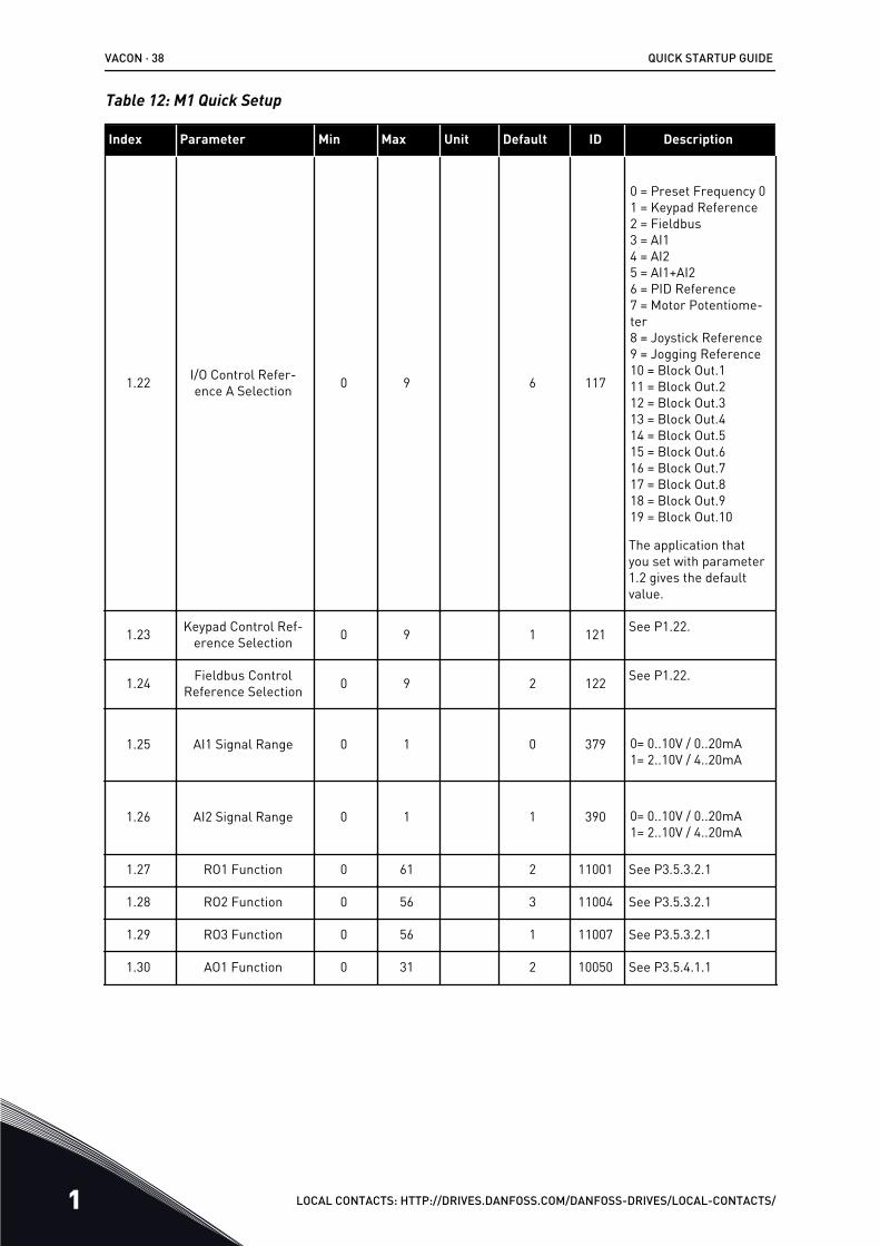
Table 12: M1 Quick Setup
Index Parameter Min Max Unit Default ID Description
1.22 I/O Control Refer-ence A Selection 0 9 6 117
0 = Preset Frequency 01 = Keypad Reference2 = Fieldbus3 = AI14 = AI25 = AI1+AI26 = PID Reference7 = Motor Potentiome-ter8 = Joystick Reference9 = Jogging Reference10 = Block Out.111 = Block Out.212 = Block Out.313 = Block Out.414 = Block Out.515 = Block Out.616 = Block Out.717 = Block Out.818 = Block Out.919 = Block Out.10
The application thatyou set with parameter1.2 gives the defaultvalue.
1.23 Keypad Control Ref-erence Selection 0 9 1 121 See P1.22.
1.24 Fieldbus ControlReference Selection 0 9 2 122 See P1.22.
1.25 AI1 Signal Range 0 1 0 379 0= 0..10V / 0..20mA1= 2..10V / 4..20mA
1.26 AI2 Signal Range 0 1 1 390 0= 0..10V / 0..20mA1= 2..10V / 4..20mA
1.27 RO1 Function 0 61 2 11001 See P3.5.3.2.1
1.28 RO2 Function 0 56 3 11004 See P3.5.3.2.1
1.29 RO3 Function 0 56 1 11007 See P3.5.3.2.1
1.30 AO1 Function 0 31 2 10050 See P3.5.4.1.1
VACON · 38 QUICK STARTUP GUIDE
1 LOCAL CONTACTS: HTTP://DRIVES.DANFOSS.COM/DANFOSS-DRIVES/LOCAL-CONTACTS/
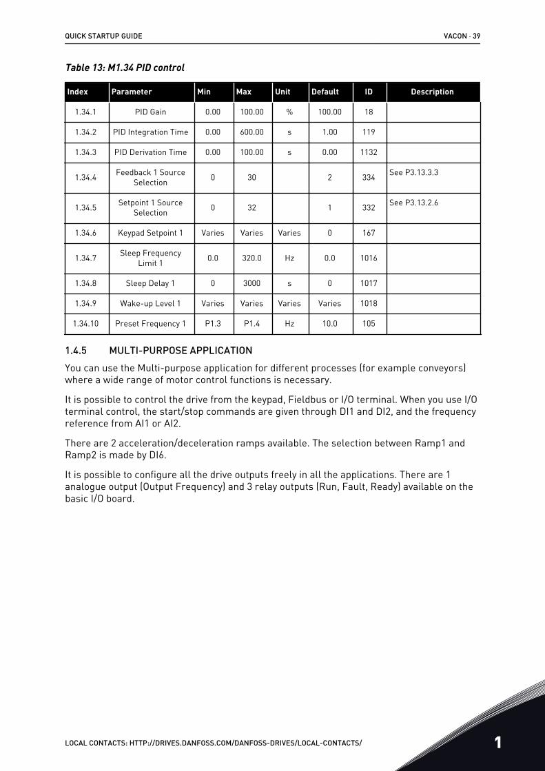
Table 13: M1.34 PID control
Index Parameter Min Max Unit Default ID Description
1.34.1 PID Gain 0.00 100.00 % 100.00 18
1.34.2 PID Integration Time 0.00 600.00 s 1.00 119
1.34.3 PID Derivation Time 0.00 100.00 s 0.00 1132
1.34.4 Feedback 1 SourceSelection 0 30 2 334 See P3.13.3.3
1.34.5 Setpoint 1 SourceSelection 0 32 1 332 See P3.13.2.6
1.34.6 Keypad Setpoint 1 Varies Varies Varies 0 167
1.34.7 Sleep FrequencyLimit 1 0.0 320.0 Hz 0.0 1016
1.34.8 Sleep Delay 1 0 3000 s 0 1017
1.34.9 Wake-up Level 1 Varies Varies Varies Varies 1018
1.34.10 Preset Frequency 1 P1.3 P1.4 Hz 10.0 105
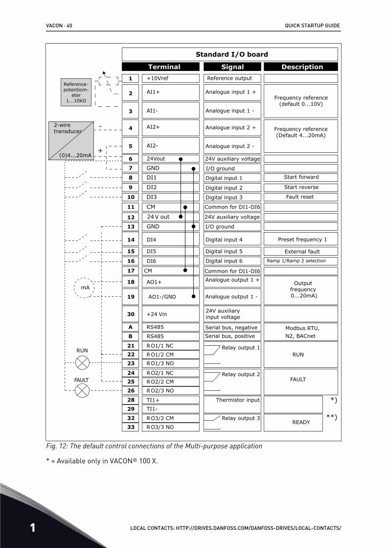
1.4.5 MULTI-PURPOSE APPLICATIONYou can use the Multi-purpose application for different processes (for example conveyors)where a wide range of motor control functions is necessary.
It is possible to control the drive from the keypad, Fieldbus or I/O terminal. When you use I/Oterminal control, the start/stop commands are given through DI1 and DI2, and the frequencyreference from AI1 or AI2.
There are 2 acceleration/deceleration ramps available. The selection between Ramp1 andRamp2 is made by DI6.
It is possible to configure all the drive outputs freely in all the applications. There are 1analogue output (Output Frequency) and 3 relay outputs (Run, Fault, Ready) available on thebasic I/O board.
QUICK STARTUP GUIDE VACON · 39
LOCAL CONTACTS: HTTP://DRIVES.DANFOSS.COM/DANFOSS-DRIVES/LOCAL-CONTACTS/ 1
1
6
2
3
4
5
18
19
30
12
7
13
8
9
10
14
15
16
212223
11
17
A
B
2425
26
32
33
Modbus RTU, N2, BACnet
28
29
(0)4...20mA+
-
*)
**)
mA
FAULT
RUNRUN
AO1-/GND
+24 Vin
24V out
GND
GND
DI1
DI2
DI3
DI4
DI5
DI6
RO1/1 NC
RO1/2 CMRO1/3 NO
CM
CM
RS485
RS485
RO2/1 NC
RO2/2 CM
RO2/3 NO
RO3/2 CM
RO3/3 NO
Standard I/O board
Terminal Signal Description+10Vref
AI1+
AI1-
AI2+
AI2-
24Vout
Reference output
Analogue input 1 +
Analogue input 1 -
Analogue input 2 +
Analogue input 2 -
24V auxiliary voltage
I/O ground
Digital input 1
Digital input 2
Digital input 3
Digital input 4
Digital input 5
Digital input 6
Common for DI1-DI6
Common for DI1-DI6
24V auxiliary voltage
I/O ground
Analogue output 1 +
Analogue output 1 -
24V auxiliaryinput voltage
Output frequency 0...20mA)
READY
Serial bus, negativeSerial bus, positive
Relay output 1
Relay output 2
Relay output 3
FAULT
Fault reset
AO1+
Frequency reference (default 0...10V)
Frequency reference (Default 4...20mA)
Start forward
Start reverse
External fault
Ramp 1/Ramp 2 selection
Reference-potentiom-
eter 1...10kΩ
Preset frequency 1
2-wiretransducer
TI1+
TI1-
Thermistor input
Fig. 12: The default control connections of the Multi-purpose application
* = Available only in VACON® 100 X.
VACON · 40 QUICK STARTUP GUIDE
1 LOCAL CONTACTS: HTTP://DRIVES.DANFOSS.COM/DANFOSS-DRIVES/LOCAL-CONTACTS/

** = For the DIP switch configurations in VACON® 100 X, see the VACON® 100 X Installationmanual.
AB
C
Fig. 13: The DIP switchA. Digital input DIP switchB. Floating
C. Connected to GND (Default)
Table 14: M1.1 Wizards
Index Parameter Min Max Unit Default ID Description
1.1.1 Startup wizard 0 1 0 1170
0 = Do not activate1 = Activate
The selection Activatestarts the Start-up wiz-ard (see Chapter 1.3 First start-up.
1.1.3 Multi-pump Wizard 0 1 0 1671
The selection Activatestarts the Multi-pumpwizard (see Chapter2.7 Multi-pump wizard).
1.1.4 Fire mode Wizard 0 1 0 1672
The selection Activatestarts the Fire modewizard (see Chapter2.8 Fire mode wizard).
QUICK STARTUP GUIDE VACON · 41
LOCAL CONTACTS: HTTP://DRIVES.DANFOSS.COM/DANFOSS-DRIVES/LOCAL-CONTACTS/ 1

Table 15: M1 Quick Setup
Index Parameter Min Max Unit Default ID Description
1.2 Application 0 5 4 212
0 = Standard1 = Local/Remote2 = Multi-Step Speed3 = PID Control4 = Multi-Purpose5 = Motor Potentiome-ter
1.3 Minimum FrequencyReference 0.00 P1.4 Hz 0.0 101
1.4 Maximum FrequencyReference P1.3 320.0 Hz 50.0 /
60.0 102
1.5 Acceleration Time 1 0.1 300.0 s 5.0 103
1.6 Deceleration Time 1 0.1 300.0 s 5.0 104
1.7 Motor Current Limit IH*0.1 IS A Varies 107
1.8 Motor Type 0 2 0 6500 = Induction Motor1 = Permanent MagnetMotor2 = Reluctance Motor
1.9 Motor Nominal Volt-age Varies Varies V Varies 110
Find this value Un onthe nameplate of themotor.
NOTE!Find out if the motorconnection is Delta orStar.
1.10 Motor Nominal Fre-quency 8.0 320.0 Hz 50 / 60 111
Find this value fn onthe nameplate of themotor.
1.11 Motor NominalSpeed 24 19200 Rpm Varies 112
Find this value nn onthe nameplate of themotor.
1.12 Motor Nominal Cur-rent IH * 0.1 IH * 2 A Varies 113
Find this value In onthe nameplate of themotor.
1.13 Motor Cos Phi(Power Factor) 0.30 1.00 Varies 120
Find this value on thenameplate of themotor.
VACON · 42 QUICK STARTUP GUIDE
1 LOCAL CONTACTS: HTTP://DRIVES.DANFOSS.COM/DANFOSS-DRIVES/LOCAL-CONTACTS/

Table 15: M1 Quick Setup
Index Parameter Min Max Unit Default ID Description
1.14 Energy Optimization 0 1 0 666 0 = Disabled1 = Enabled
1.15 Identification 0 2 0 631 0 = No action1 = At standstill2 = With rotation
1.16 Start Function 0 1 0 505 0 = Ramping1 = Flying Start
1.17 Stop Function 0 1 0 506 0 = Coasting1 = Ramping
1.18 Automatic Reset 0 1 0 731 0 = Disabled1 = Enabled
1.19 Response to ExternalFault 0 3 2 701
0 = No action1 = Alarm2 = Fault (Stop accord-ing to stop mode)3 = Fault (Stop bycoasting)
1.20 Response to AI LowFault 0 5 0 700
0 = No action1 = Alarm2 = Alarm+preset faultfrequency (P3.9.1.13)3 = Alarm + previousfrequency4 = Fault (Stop accord-ing to stop mode)5 = Fault (Stop bycoasting)
1.21 Remote ControlPlace 0 1 0 172 0 = I/O control
1 = Fieldbus control
QUICK STARTUP GUIDE VACON · 43
LOCAL CONTACTS: HTTP://DRIVES.DANFOSS.COM/DANFOSS-DRIVES/LOCAL-CONTACTS/ 1

Table 15: M1 Quick Setup
Index Parameter Min Max Unit Default ID Description
1.22 I/O Control Refer-ence A Selection 0 9 5 117
0 = Preset Frequency 01 = Keypad Reference2 = Fieldbus3 = AI14 = AI25 = AI1+AI26 = PID Reference7 = Motor Potentiome-ter8 = Joystick Reference9 = Jogging Reference10 = Block Out.111 = Block Out.212 = Block Out.313 = Block Out.414 = Block Out.515 = Block Out.616 = Block Out.717 = Block Out.818 = Block Out.919 = Block Out.10
The application thatyou set with parameter1.2 gives the defaultvalue.
1.23 Keypad Control Ref-erence Selection 0 9 1 121 See P1.22.
1.24 Fieldbus ControlReference Selection 0 9 2 122 See P1.22.
1.25 AI1 Signal Range 0 1 0 379 0= 0..10V / 0..20mA1= 2..10V / 4..20mA
1.26 AI2 Signal Range 0 1 0 390 0= 0..10V / 0..20mA1= 2..10V / 4..20mA
1.27 RO1 Function 0 61 2 11001 See P3.5.3.2.1
1.28 RO2 Function 0 56 3 11004 See P3.5.3.2.1
1.29 RO3 Function 0 56 1 11007 See P3.5.3.2.1
1.30 AO1 Function 0 31 2 10050 See P3.5.4.1.1
VACON · 44 QUICK STARTUP GUIDE
1 LOCAL CONTACTS: HTTP://DRIVES.DANFOSS.COM/DANFOSS-DRIVES/LOCAL-CONTACTS/
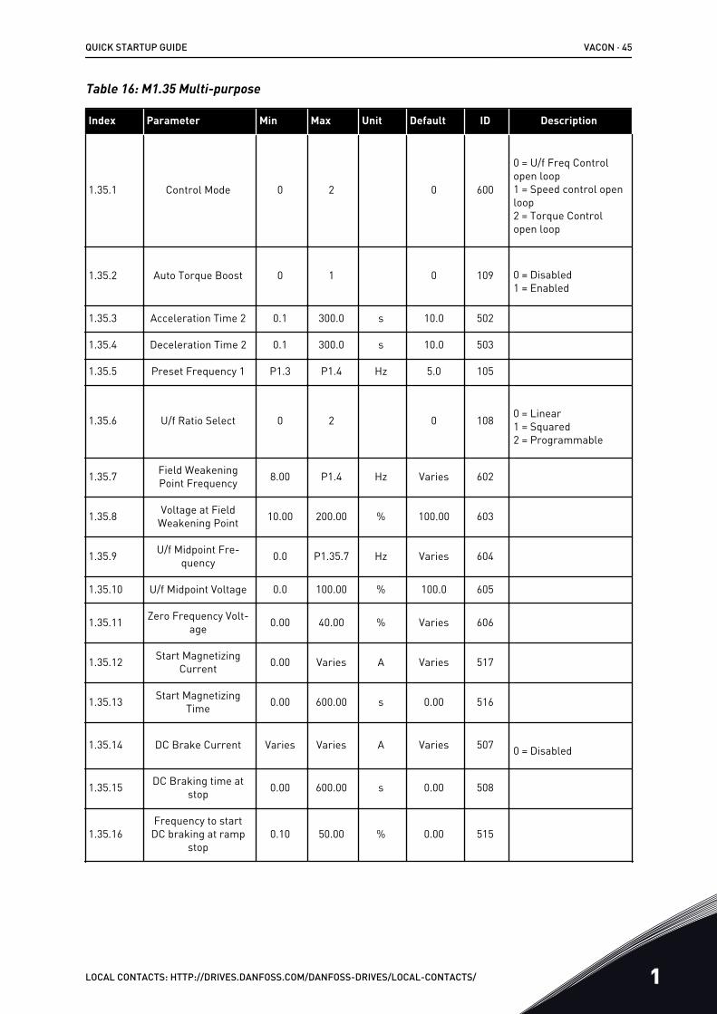
Table 16: M1.35 Multi-purpose
Index Parameter Min Max Unit Default ID Description
1.35.1 Control Mode 0 2 0 600
0 = U/f Freq Controlopen loop1 = Speed control openloop2 = Torque Controlopen loop
1.35.2 Auto Torque Boost 0 1 0 109 0 = Disabled1 = Enabled
1.35.3 Acceleration Time 2 0.1 300.0 s 10.0 502
1.35.4 Deceleration Time 2 0.1 300.0 s 10.0 503
1.35.5 Preset Frequency 1 P1.3 P1.4 Hz 5.0 105
1.35.6 U/f Ratio Select 0 2 0 108 0 = Linear1 = Squared2 = Programmable
1.35.7 Field WeakeningPoint Frequency 8.00 P1.4 Hz Varies 602
1.35.8 Voltage at FieldWeakening Point 10.00 200.00 % 100.00 603
1.35.9 U/f Midpoint Fre-quency 0.0 P1.35.7 Hz Varies 604
1.35.10 U/f Midpoint Voltage 0.0 100.00 % 100.0 605
1.35.11 Zero Frequency Volt-age 0.00 40.00 % Varies 606
1.35.12 Start MagnetizingCurrent 0.00 Varies A Varies 517
1.35.13 Start MagnetizingTime 0.00 600.00 s 0.00 516
1.35.14 DC Brake Current Varies Varies A Varies 507 0 = Disabled
1.35.15 DC Braking time atstop 0.00 600.00 s 0.00 508
1.35.16Frequency to start
DC braking at rampstop
0.10 50.00 % 0.00 515
QUICK STARTUP GUIDE VACON · 45
LOCAL CONTACTS: HTTP://DRIVES.DANFOSS.COM/DANFOSS-DRIVES/LOCAL-CONTACTS/ 1
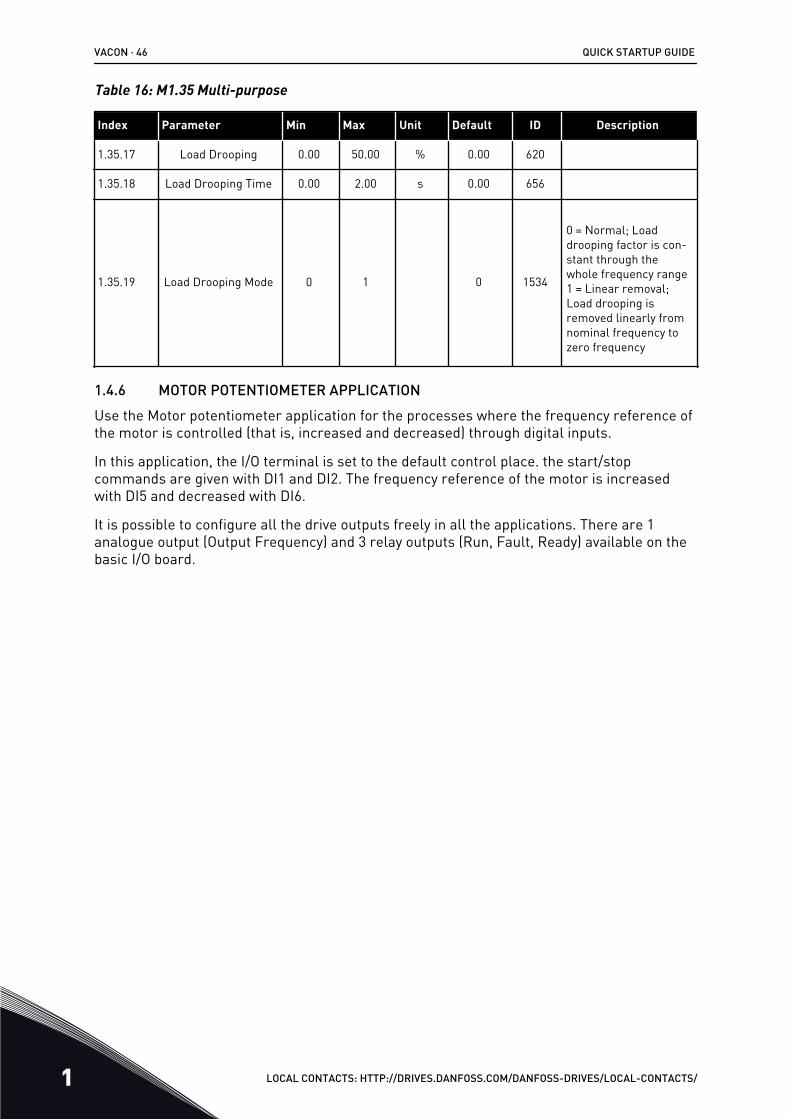
Table 16: M1.35 Multi-purpose
Index Parameter Min Max Unit Default ID Description
1.35.17 Load Drooping 0.00 50.00 % 0.00 620
1.35.18 Load Drooping Time 0.00 2.00 s 0.00 656
1.35.19 Load Drooping Mode 0 1 0 1534
0 = Normal; Loaddrooping factor is con-stant through thewhole frequency range1 = Linear removal;Load drooping isremoved linearly fromnominal frequency tozero frequency
1.4.6 MOTOR POTENTIOMETER APPLICATIONUse the Motor potentiometer application for the processes where the frequency reference ofthe motor is controlled (that is, increased and decreased) through digital inputs.
In this application, the I/O terminal is set to the default control place. the start/stopcommands are given with DI1 and DI2. The frequency reference of the motor is increasedwith DI5 and decreased with DI6.
It is possible to configure all the drive outputs freely in all the applications. There are 1analogue output (Output Frequency) and 3 relay outputs (Run, Fault, Ready) available on thebasic I/O board.
VACON · 46 QUICK STARTUP GUIDE
1 LOCAL CONTACTS: HTTP://DRIVES.DANFOSS.COM/DANFOSS-DRIVES/LOCAL-CONTACTS/
1
6
2
3
4
5
18
19
30
12
7
13
8
9
10
14
15
16
212223
11
17
A
B
2425
26
32
33
28
29*)
**)
mA
FAULT
RUNRUN
AO1-/GND
+24 Vin
24V out
GND
GND
DI1
DI2
DI3
DI4
DI5
DI6
RO1/1 NC
RO1/2 CMRO1/3 NO
CM
CM
RS485
RS485
RO2/1 NC
RO2/2 CM
RO2/3 NO
RO3/2 CM
RO3/3 NO
Standard I/O board
Terminal Signal Description+10Vref
AI1+
AI1-
AI2+
AI2-
24Vout
Reference output
Analogue input 1 +
Analogue input 1 -
Analogue input 2 +
Analogue input 2 -
Not used
Not used
24V auxiliary voltage
I/O ground
Digital input 1
Digital input 2
Digital input 3
Digital input 4
Digital input 5
Digital input 6
Start forward
Start reverse
External fault
Common for DI1-DI6
Common for DI1-DI6
24V auxiliary voltage
I/O ground
Analogue output 1 +
Analogue output 1 -
24V auxiliaryinput voltage
Output frequency 0...20mA)
Modbus, RTU, BACnet, N2
READY
Serial bus, negativeSerial bus, positive
Relay output 1
Relay output 2
Relay output 3
FAULT
Preset frequency 1
Frequency reference UP
Frequency reference DOWN
AO1+
TI1+
TI1-
Thermistor input
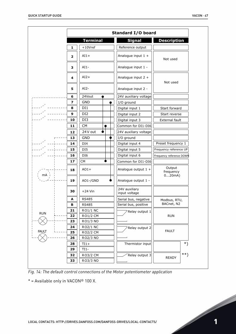
Fig. 14: The default control connections of the Motor potentiometer application
* = Available only in VACON® 100 X.
QUICK STARTUP GUIDE VACON · 47
LOCAL CONTACTS: HTTP://DRIVES.DANFOSS.COM/DANFOSS-DRIVES/LOCAL-CONTACTS/ 1
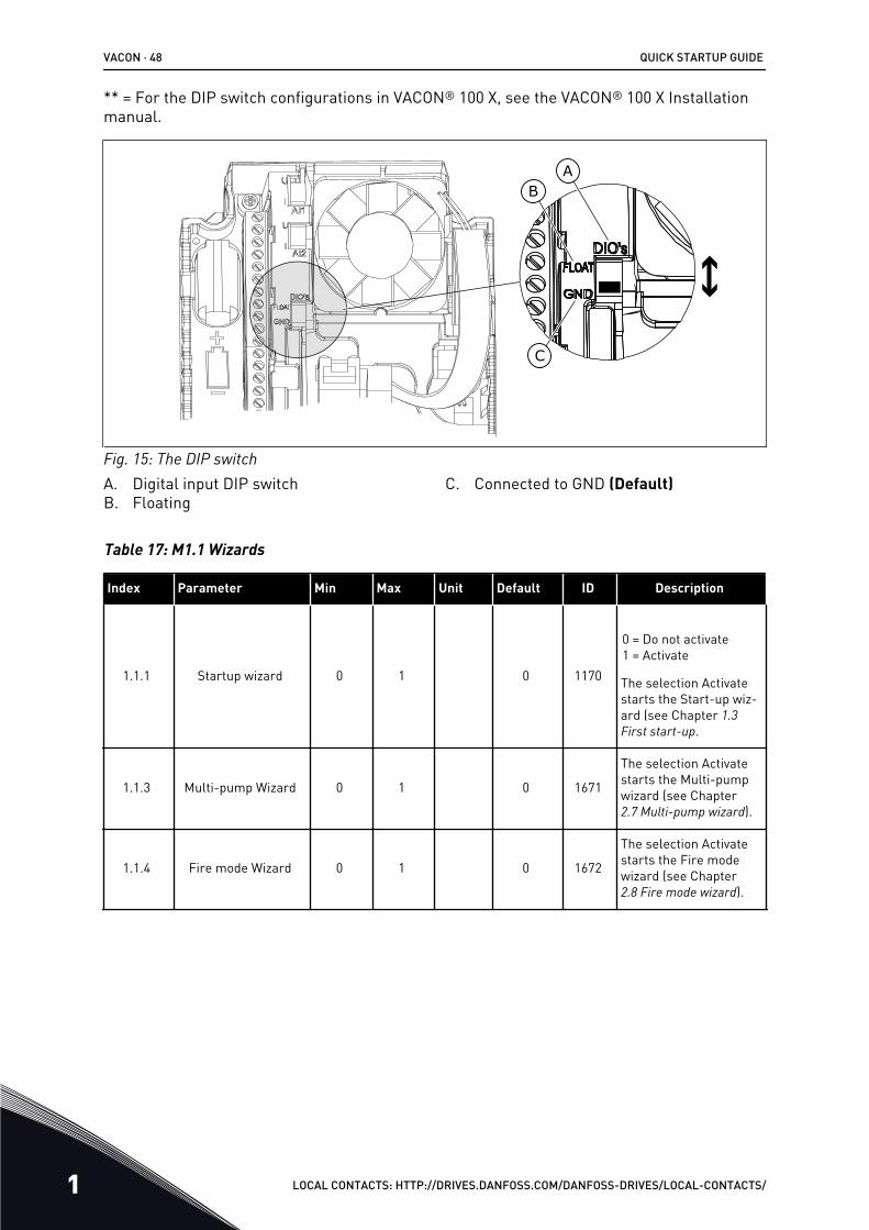
** = For the DIP switch configurations in VACON® 100 X, see the VACON® 100 X Installationmanual.
AB
C
Fig. 15: The DIP switchA. Digital input DIP switchB. Floating
C. Connected to GND (Default)
Table 17: M1.1 Wizards
Index Parameter Min Max Unit Default ID Description
1.1.1 Startup wizard 0 1 0 1170
0 = Do not activate1 = Activate
The selection Activatestarts the Start-up wiz-ard (see Chapter 1.3 First start-up.
1.1.3 Multi-pump Wizard 0 1 0 1671
The selection Activatestarts the Multi-pumpwizard (see Chapter2.7 Multi-pump wizard).
1.1.4 Fire mode Wizard 0 1 0 1672
The selection Activatestarts the Fire modewizard (see Chapter2.8 Fire mode wizard).
VACON · 48 QUICK STARTUP GUIDE
1 LOCAL CONTACTS: HTTP://DRIVES.DANFOSS.COM/DANFOSS-DRIVES/LOCAL-CONTACTS/
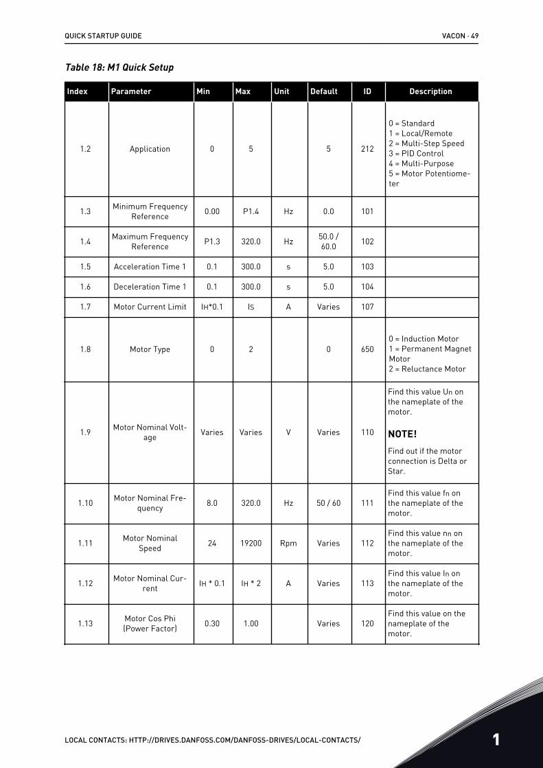
Table 18: M1 Quick Setup
Index Parameter Min Max Unit Default ID Description
1.2 Application 0 5 5 212
0 = Standard1 = Local/Remote2 = Multi-Step Speed3 = PID Control4 = Multi-Purpose5 = Motor Potentiome-ter
1.3 Minimum FrequencyReference 0.00 P1.4 Hz 0.0 101
1.4 Maximum FrequencyReference P1.3 320.0 Hz 50.0 /
60.0 102
1.5 Acceleration Time 1 0.1 300.0 s 5.0 103
1.6 Deceleration Time 1 0.1 300.0 s 5.0 104
1.7 Motor Current Limit IH*0.1 IS A Varies 107
1.8 Motor Type 0 2 0 6500 = Induction Motor1 = Permanent MagnetMotor2 = Reluctance Motor
1.9 Motor Nominal Volt-age Varies Varies V Varies 110
Find this value Un onthe nameplate of themotor.
NOTE!Find out if the motorconnection is Delta orStar.
1.10 Motor Nominal Fre-quency 8.0 320.0 Hz 50 / 60 111
Find this value fn onthe nameplate of themotor.
1.11 Motor NominalSpeed 24 19200 Rpm Varies 112
Find this value nn onthe nameplate of themotor.
1.12 Motor Nominal Cur-rent IH * 0.1 IH * 2 A Varies 113
Find this value In onthe nameplate of themotor.
1.13 Motor Cos Phi(Power Factor) 0.30 1.00 Varies 120
Find this value on thenameplate of themotor.
QUICK STARTUP GUIDE VACON · 49
LOCAL CONTACTS: HTTP://DRIVES.DANFOSS.COM/DANFOSS-DRIVES/LOCAL-CONTACTS/ 1
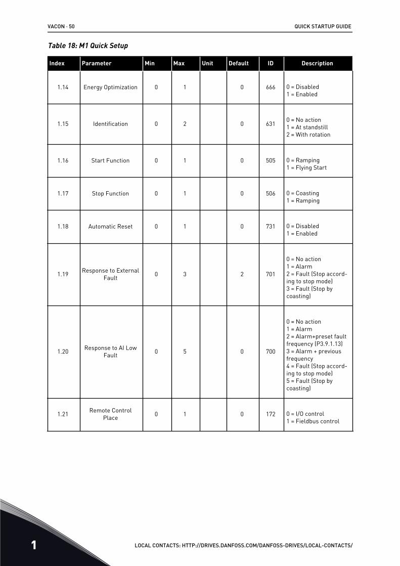
Table 18: M1 Quick Setup
Index Parameter Min Max Unit Default ID Description
1.14 Energy Optimization 0 1 0 666 0 = Disabled1 = Enabled
1.15 Identification 0 2 0 631 0 = No action1 = At standstill2 = With rotation
1.16 Start Function 0 1 0 505 0 = Ramping1 = Flying Start
1.17 Stop Function 0 1 0 506 0 = Coasting1 = Ramping
1.18 Automatic Reset 0 1 0 731 0 = Disabled1 = Enabled
1.19 Response to ExternalFault 0 3 2 701
0 = No action1 = Alarm2 = Fault (Stop accord-ing to stop mode)3 = Fault (Stop bycoasting)
1.20 Response to AI LowFault 0 5 0 700
0 = No action1 = Alarm2 = Alarm+preset faultfrequency (P3.9.1.13)3 = Alarm + previousfrequency4 = Fault (Stop accord-ing to stop mode)5 = Fault (Stop bycoasting)
1.21 Remote ControlPlace 0 1 0 172 0 = I/O control
1 = Fieldbus control
VACON · 50 QUICK STARTUP GUIDE
1 LOCAL CONTACTS: HTTP://DRIVES.DANFOSS.COM/DANFOSS-DRIVES/LOCAL-CONTACTS/
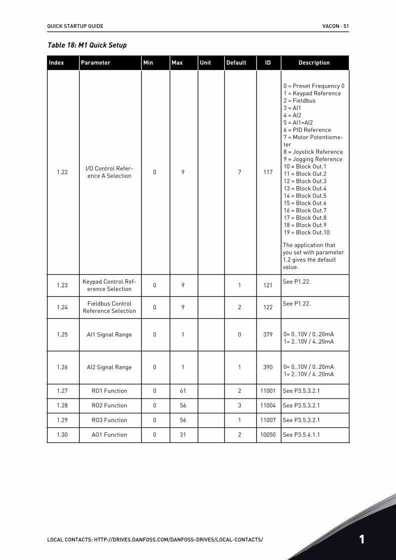
Table 18: M1 Quick Setup
Index Parameter Min Max Unit Default ID Description
1.22 I/O Control Refer-ence A Selection 0 9 7 117
0 = Preset Frequency 01 = Keypad Reference2 = Fieldbus3 = AI14 = AI25 = AI1+AI26 = PID Reference7 = Motor Potentiome-ter8 = Joystick Reference9 = Jogging Reference10 = Block Out.111 = Block Out.212 = Block Out.313 = Block Out.414 = Block Out.515 = Block Out.616 = Block Out.717 = Block Out.818 = Block Out.919 = Block Out.10
The application thatyou set with parameter1.2 gives the defaultvalue.
1.23 Keypad Control Ref-erence Selection 0 9 1 121 See P1.22.
1.24 Fieldbus ControlReference Selection 0 9 2 122 See P1.22.
1.25 AI1 Signal Range 0 1 0 379 0= 0..10V / 0..20mA1= 2..10V / 4..20mA
1.26 AI2 Signal Range 0 1 1 390 0= 0..10V / 0..20mA1= 2..10V / 4..20mA
1.27 RO1 Function 0 61 2 11001 See P3.5.3.2.1
1.28 RO2 Function 0 56 3 11004 See P3.5.3.2.1
1.29 RO3 Function 0 56 1 11007 See P3.5.3.2.1
1.30 AO1 Function 0 31 2 10050 See P3.5.4.1.1
QUICK STARTUP GUIDE VACON · 51
LOCAL CONTACTS: HTTP://DRIVES.DANFOSS.COM/DANFOSS-DRIVES/LOCAL-CONTACTS/ 1

Table 19: M1.36 Motor Potentiometer
Index Parameter Min Max Unit Default ID Description
1.36.1 Motor PotentiometerRamp Time 0.1 500.0 Hz/s 10.0 331
1.31.2 Motor PotentiometerReset 0 2 1 367
0 = No reset1 = Reset if stopped2 = Reset if powereddown
1.31.2 Preset Frequency 1 P1.3 P1.4 Hz 10.0 105
VACON · 52 QUICK STARTUP GUIDE
1 LOCAL CONTACTS: HTTP://DRIVES.DANFOSS.COM/DANFOSS-DRIVES/LOCAL-CONTACTS/
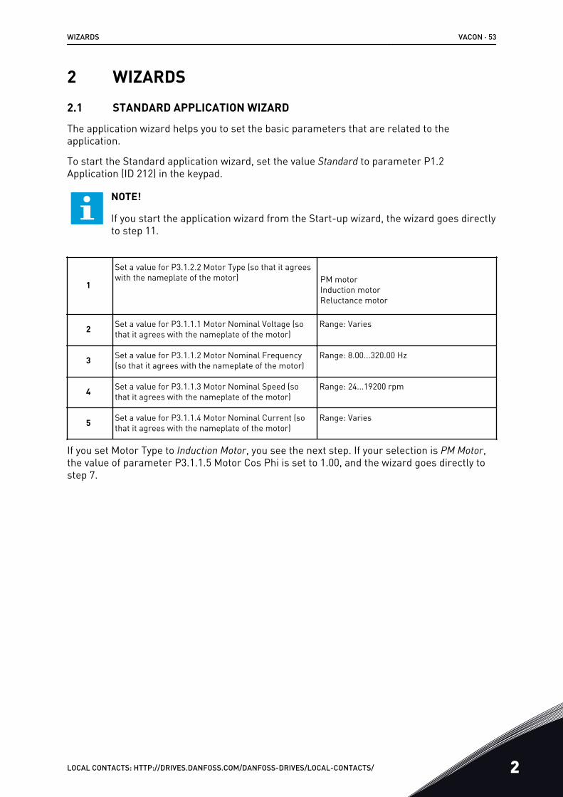
2 WIZARDS2.1 STANDARD APPLICATION WIZARD
The application wizard helps you to set the basic parameters that are related to theapplication.
To start the Standard application wizard, set the value Standard to parameter P1.2Application (ID 212) in the keypad.
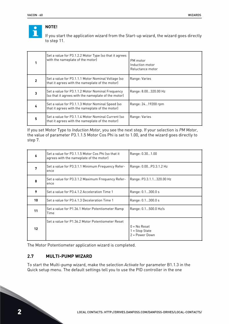
NOTE!
If you start the application wizard from the Start-up wizard, the wizard goes directlyto step 11.
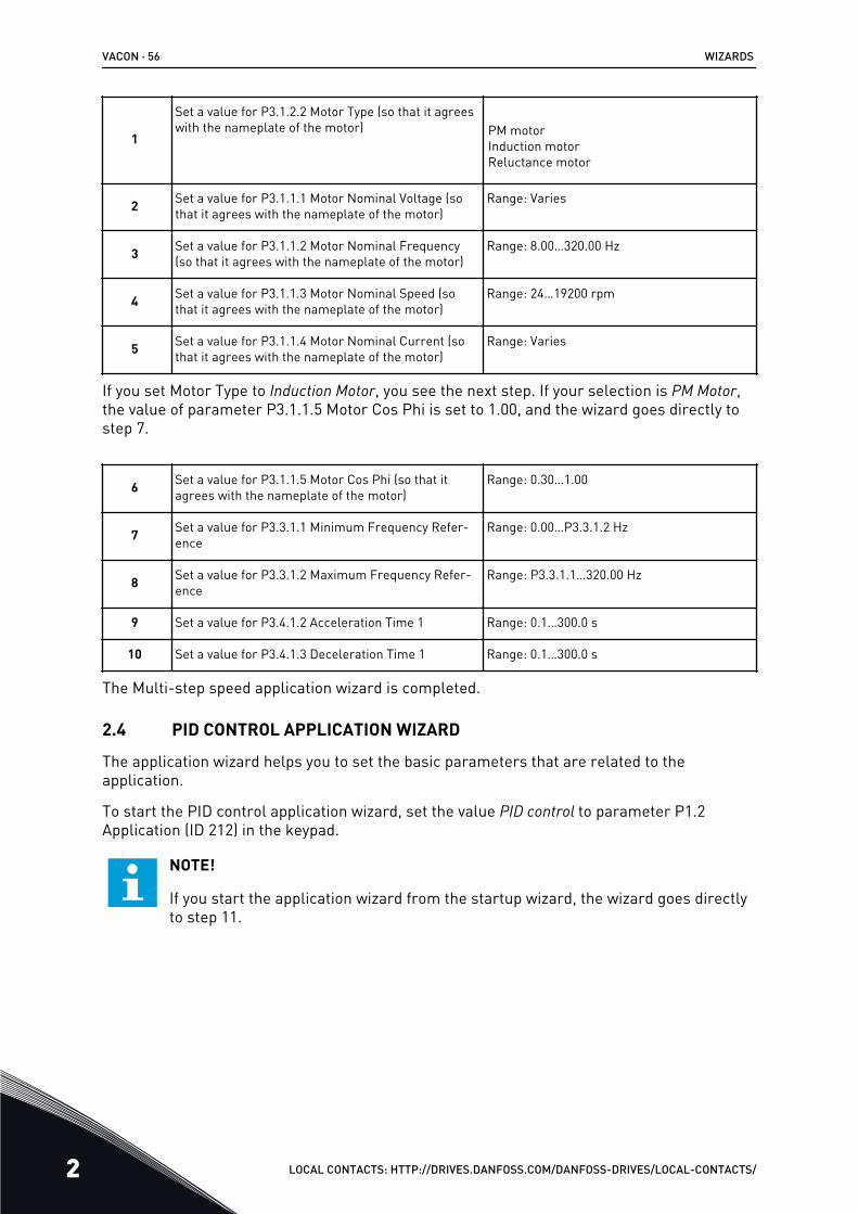
1
Set a value for P3.1.2.2 Motor Type (so that it agreeswith the nameplate of the motor) PM motor
Induction motorReluctance motor
2 Set a value for P3.1.1.1 Motor Nominal Voltage (sothat it agrees with the nameplate of the motor)
Range: Varies
3 Set a value for P3.1.1.2 Motor Nominal Frequency(so that it agrees with the nameplate of the motor)
Range: 8.00...320.00 Hz
4 Set a value for P3.1.1.3 Motor Nominal Speed (sothat it agrees with the nameplate of the motor)
Range: 24...19200 rpm
5 Set a value for P3.1.1.4 Motor Nominal Current (sothat it agrees with the nameplate of the motor)
Range: Varies
If you set Motor Type to Induction Motor, you see the next step. If your selection is PM Motor,the value of parameter P3.1.1.5 Motor Cos Phi is set to 1.00, and the wizard goes directly tostep 7.
WIZARDS VACON · 53
LOCAL CONTACTS: HTTP://DRIVES.DANFOSS.COM/DANFOSS-DRIVES/LOCAL-CONTACTS/ 2
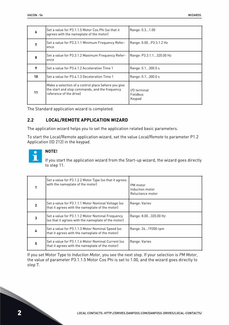
6 Set a value for P3.1.1.5 Motor Cos Phi (so that itagrees with the nameplate of the motor)
Range: 0.3...1.00
7 Set a value for P3.3.1.1 Minimum Frequency Refer-ence
Range: 0.00...P3.3.1.2 Hz
8 Set a value for P3.3.1.2 Maximum Frequency Refer-ence
Range: P3.3.1.1...320.00 Hz
9 Set a value for P3.4.1.2 Acceleration Time 1 Range: 0.1...300.0 s
10 Set a value for P3.4.1.3 Deceleration Time 1 Range: 0.1...300.0 s
11
Make a selection of a control place (where you givethe start and stop commands, and the frequencyreference of the drive)
I/O terminalFieldbusKeypad
The Standard application wizard is completed.
2.2 LOCAL/REMOTE APPLICATION WIZARD
The application wizard helps you to set the application related basic parameters.
To start the Local/Remote application wizard, set the value Local/Remote to parameter P1.2Application (ID 212) in the keypad.
NOTE!
If you start the application wizard from the Start-up wizard, the wizard goes directlyto step 11.
1
Set a value for P3.1.2.2 Motor Type (so that it agreeswith the nameplate of the motor) PM motor
Induction motorReluctance motor
2 Set a value for P3.1.1.1 Motor Nominal Voltage (sothat it agrees with the nameplate of the motor)
Range: Varies
3 Set a value for P3.1.1.2 Motor Nominal Frequency(so that it agrees with the nameplate of the motor)
Range: 8.00...320.00 Hz
4 Set a value for P3.1.1.3 Motor Nominal Speed (sothat it agrees with the nameplate of the motor)
Range: 24...19200 rpm
5 Set a value for P3.1.1.4 Motor Nominal Current (sothat it agrees with the nameplate of the motor)
Range: Varies
If you set Motor Type to Induction Motor, you see the next step. If your selection is PM Motor,the value of parameter P3.1.1.5 Motor Cos Phi is set to 1.00, and the wizard goes directly tostep 7.
VACON · 54 WIZARDS
2 LOCAL CONTACTS: HTTP://DRIVES.DANFOSS.COM/DANFOSS-DRIVES/LOCAL-CONTACTS/
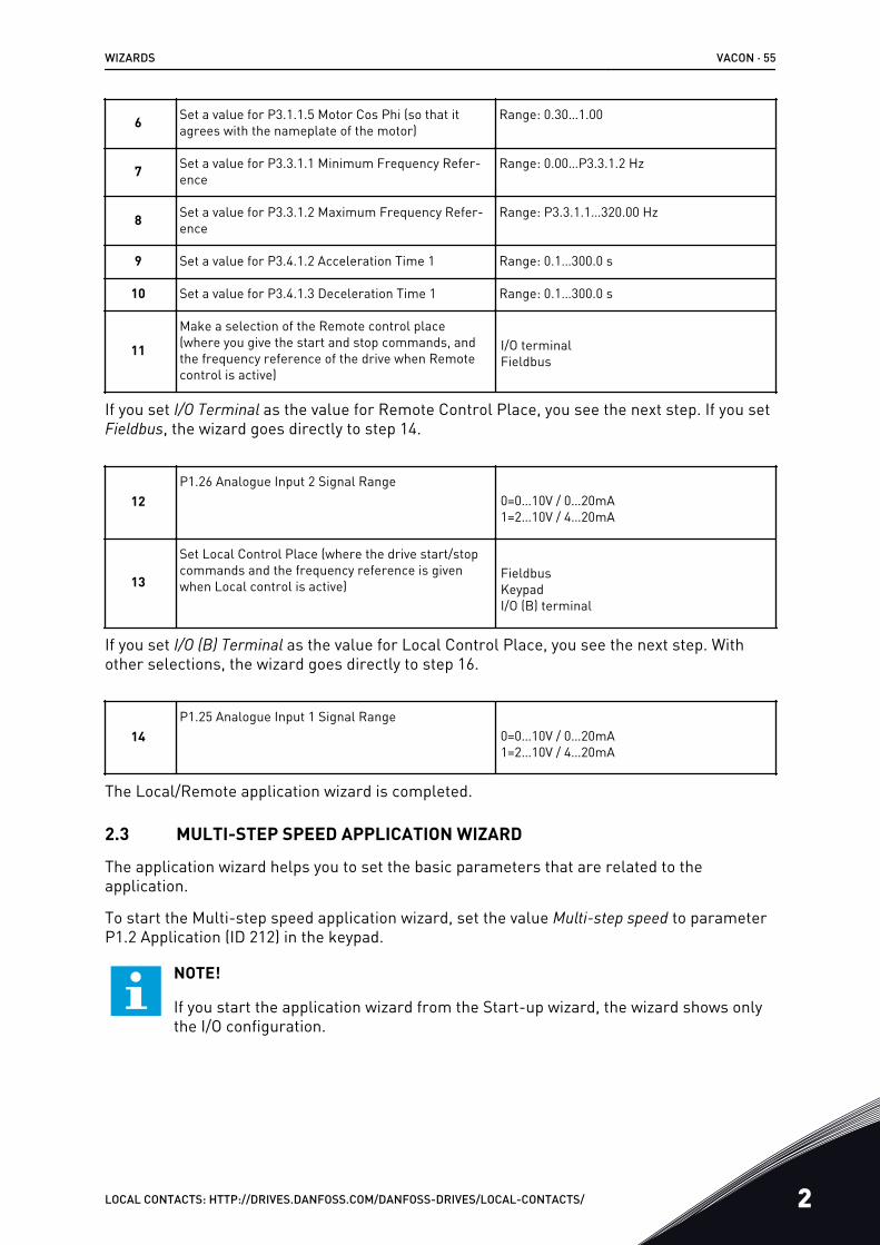
6 Set a value for P3.1.1.5 Motor Cos Phi (so that itagrees with the nameplate of the motor)
Range: 0.30…1.00
7 Set a value for P3.3.1.1 Minimum Frequency Refer-ence
Range: 0.00…P3.3.1.2 Hz
8 Set a value for P3.3.1.2 Maximum Frequency Refer-ence
Range: P3.3.1.1…320.00 Hz
9 Set a value for P3.4.1.2 Acceleration Time 1 Range: 0.1…300.0 s
10 Set a value for P3.4.1.3 Deceleration Time 1 Range: 0.1…300.0 s
11
Make a selection of the Remote control place(where you give the start and stop commands, andthe frequency reference of the drive when Remotecontrol is active)
I/O terminalFieldbus
If you set I/O Terminal as the value for Remote Control Place, you see the next step. If you setFieldbus, the wizard goes directly to step 14.
12P1.26 Analogue Input 2 Signal Range
0=0…10V / 0…20mA1=2…10V / 4…20mA
13
Set Local Control Place (where the drive start/stopcommands and the frequency reference is givenwhen Local control is active)
FieldbusKeypadI/O (B) terminal
If you set I/O (B) Terminal as the value for Local Control Place, you see the next step. Withother selections, the wizard goes directly to step 16.
14P1.25 Analogue Input 1 Signal Range
0=0…10V / 0…20mA1=2…10V / 4…20mA
The Local/Remote application wizard is completed.
2.3 MULTI-STEP SPEED APPLICATION WIZARD
The application wizard helps you to set the basic parameters that are related to theapplication.
To start the Multi-step speed application wizard, set the value Multi-step speed to parameterP1.2 Application (ID 212) in the keypad.
NOTE!
If you start the application wizard from the Start-up wizard, the wizard shows onlythe I/O configuration.
WIZARDS VACON · 55
LOCAL CONTACTS: HTTP://DRIVES.DANFOSS.COM/DANFOSS-DRIVES/LOCAL-CONTACTS/ 2
1
Set a value for P3.1.2.2 Motor Type (so that it agreeswith the nameplate of the motor) PM motor
Induction motorReluctance motor
2 Set a value for P3.1.1.1 Motor Nominal Voltage (sothat it agrees with the nameplate of the motor)
Range: Varies
3 Set a value for P3.1.1.2 Motor Nominal Frequency(so that it agrees with the nameplate of the motor)
Range: 8.00…320.00 Hz
4 Set a value for P3.1.1.3 Motor Nominal Speed (sothat it agrees with the nameplate of the motor)
Range: 24…19200 rpm
5 Set a value for P3.1.1.4 Motor Nominal Current (sothat it agrees with the nameplate of the motor)
Range: Varies
If you set Motor Type to Induction Motor, you see the next step. If your selection is PM Motor,the value of parameter P3.1.1.5 Motor Cos Phi is set to 1.00, and the wizard goes directly tostep 7.
6 Set a value for P3.1.1.5 Motor Cos Phi (so that itagrees with the nameplate of the motor)
Range: 0.30…1.00
7 Set a value for P3.3.1.1 Minimum Frequency Refer-ence
Range: 0.00…P3.3.1.2 Hz
8 Set a value for P3.3.1.2 Maximum Frequency Refer-ence
Range: P3.3.1.1…320.00 Hz
9 Set a value for P3.4.1.2 Acceleration Time 1 Range: 0.1…300.0 s
10 Set a value for P3.4.1.3 Deceleration Time 1 Range: 0.1…300.0 s
The Multi-step speed application wizard is completed.
2.4 PID CONTROL APPLICATION WIZARD
The application wizard helps you to set the basic parameters that are related to theapplication.
To start the PID control application wizard, set the value PID control to parameter P1.2Application (ID 212) in the keypad.
NOTE!
If you start the application wizard from the startup wizard, the wizard goes directlyto step 11.
VACON · 56 WIZARDS
2 LOCAL CONTACTS: HTTP://DRIVES.DANFOSS.COM/DANFOSS-DRIVES/LOCAL-CONTACTS/
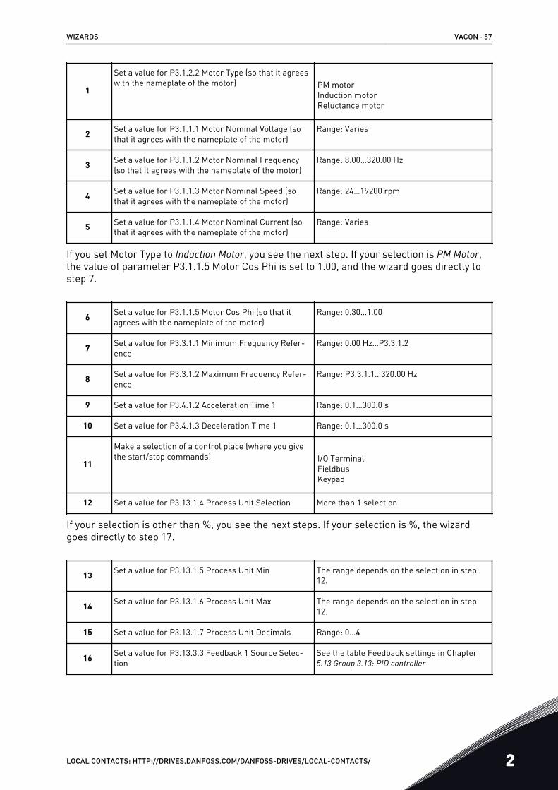
1
Set a value for P3.1.2.2 Motor Type (so that it agreeswith the nameplate of the motor) PM motor
Induction motorReluctance motor
2 Set a value for P3.1.1.1 Motor Nominal Voltage (sothat it agrees with the nameplate of the motor)
Range: Varies
3 Set a value for P3.1.1.2 Motor Nominal Frequency(so that it agrees with the nameplate of the motor)
Range: 8.00…320.00 Hz
4 Set a value for P3.1.1.3 Motor Nominal Speed (sothat it agrees with the nameplate of the motor)
Range: 24…19200 rpm
5 Set a value for P3.1.1.4 Motor Nominal Current (sothat it agrees with the nameplate of the motor)
Range: Varies
If you set Motor Type to Induction Motor, you see the next step. If your selection is PM Motor,the value of parameter P3.1.1.5 Motor Cos Phi is set to 1.00, and the wizard goes directly tostep 7.
6 Set a value for P3.1.1.5 Motor Cos Phi (so that itagrees with the nameplate of the motor)
Range: 0.30…1.00
7 Set a value for P3.3.1.1 Minimum Frequency Refer-ence
Range: 0.00 Hz…P3.3.1.2
8 Set a value for P3.3.1.2 Maximum Frequency Refer-ence
Range: P3.3.1.1…320.00 Hz
9 Set a value for P3.4.1.2 Acceleration Time 1 Range: 0.1…300.0 s
10 Set a value for P3.4.1.3 Deceleration Time 1 Range: 0.1…300.0 s
11
Make a selection of a control place (where you givethe start/stop commands) I/O Terminal
FieldbusKeypad
12 Set a value for P3.13.1.4 Process Unit Selection More than 1 selection
If your selection is other than %, you see the next steps. If your selection is %, the wizardgoes directly to step 17.
13 Set a value for P3.13.1.5 Process Unit Min The range depends on the selection in step12.
14 Set a value for P3.13.1.6 Process Unit Max The range depends on the selection in step12.
15 Set a value for P3.13.1.7 Process Unit Decimals Range: 0…4
16 Set a value for P3.13.3.3 Feedback 1 Source Selec-tion
See the table Feedback settings in Chapter5.13 Group 3.13: PID controller
WIZARDS VACON · 57
LOCAL CONTACTS: HTTP://DRIVES.DANFOSS.COM/DANFOSS-DRIVES/LOCAL-CONTACTS/ 2
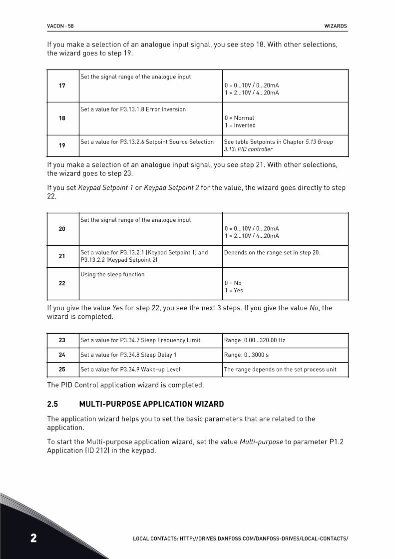
If you make a selection of an analogue input signal, you see step 18. With other selections,the wizard goes to step 19.
17Set the signal range of the analogue input
0 = 0…10V / 0…20mA1 = 2…10V / 4…20mA
18Set a value for P3.13.1.8 Error Inversion
0 = Normal1 = Inverted
19 Set a value for P3.13.2.6 Setpoint Source Selection See table Setpoints in Chapter 5.13 Group 3.13: PID controller
If you make a selection of an analogue input signal, you see step 21. With other selections,the wizard goes to step 23.
If you set Keypad Setpoint 1 or Keypad Setpoint 2 for the value, the wizard goes directly to step22.
20Set the signal range of the analogue input
0 = 0…10V / 0…20mA1 = 2…10V / 4…20mA
21 Set a value for P3.13.2.1 (Keypad Setpoint 1) andP3.13.2.2 (Keypad Setpoint 2)
Depends on the range set in step 20.
22Using the sleep function
0 = No1 = Yes
If you give the value Yes for step 22, you see the next 3 steps. If you give the value No, thewizard is completed.
23 Set a value for P3.34.7 Sleep Frequency Limit Range: 0.00…320.00 Hz
24 Set a value for P3.34.8 Sleep Delay 1 Range: 0…3000 s
25 Set a value for P3.34.9 Wake-up Level The range depends on the set process unit
The PID Control application wizard is completed.
2.5 MULTI-PURPOSE APPLICATION WIZARD
The application wizard helps you to set the basic parameters that are related to theapplication.
To start the Multi-purpose application wizard, set the value Multi-purpose to parameter P1.2Application (ID 212) in the keypad.
VACON · 58 WIZARDS
2 LOCAL CONTACTS: HTTP://DRIVES.DANFOSS.COM/DANFOSS-DRIVES/LOCAL-CONTACTS/
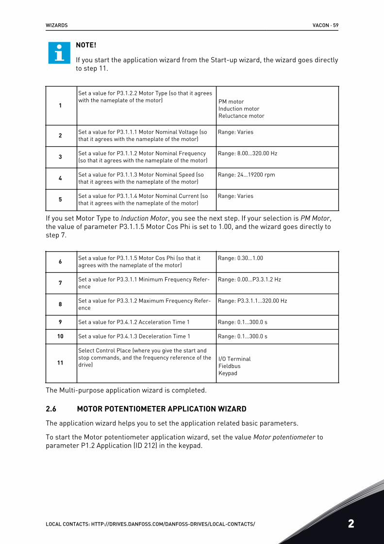
NOTE!
If you start the application wizard from the Start-up wizard, the wizard goes directlyto step 11.
1
Set a value for P3.1.2.2 Motor Type (so that it agreeswith the nameplate of the motor) PM motor
Induction motorReluctance motor
2 Set a value for P3.1.1.1 Motor Nominal Voltage (sothat it agrees with the nameplate of the motor)
Range: Varies
3 Set a value for P3.1.1.2 Motor Nominal Frequency(so that it agrees with the nameplate of the motor)
Range: 8.00…320.00 Hz
4 Set a value for P3.1.1.3 Motor Nominal Speed (sothat it agrees with the nameplate of the motor)
Range: 24…19200 rpm
5 Set a value for P3.1.1.4 Motor Nominal Current (sothat it agrees with the nameplate of the motor)
Range: Varies
If you set Motor Type to Induction Motor, you see the next step. If your selection is PM Motor,the value of parameter P3.1.1.5 Motor Cos Phi is set to 1.00, and the wizard goes directly tostep 7.
6 Set a value for P3.1.1.5 Motor Cos Phi (so that itagrees with the nameplate of the motor)
Range: 0.30…1.00
7 Set a value for P3.3.1.1 Minimum Frequency Refer-ence
Range: 0.00…P3.3.1.2 Hz
8 Set a value for P3.3.1.2 Maximum Frequency Refer-ence
Range: P3.3.1.1…320.00 Hz
9 Set a value for P3.4.1.2 Acceleration Time 1 Range: 0.1…300.0 s
10 Set a value for P3.4.1.3 Deceleration Time 1 Range: 0.1…300.0 s
11
Select Control Place (where you give the start andstop commands, and the frequency reference of thedrive)
I/O TerminalFieldbusKeypad
The Multi-purpose application wizard is completed.
2.6 MOTOR POTENTIOMETER APPLICATION WIZARD
The application wizard helps you to set the application related basic parameters.
To start the Motor potentiometer application wizard, set the value Motor potentiometer toparameter P1.2 Application (ID 212) in the keypad.
WIZARDS VACON · 59
LOCAL CONTACTS: HTTP://DRIVES.DANFOSS.COM/DANFOSS-DRIVES/LOCAL-CONTACTS/ 2
NOTE!
If you start the application wizard from the Start-up wizard, the wizard goes directlyto step 11.
1
Set a value for P3.1.2.2 Motor Type (so that it agreeswith the nameplate of the motor) PM motor
Induction motorReluctance motor
2 Set a value for P3.1.1.1 Motor Nominal Voltage (sothat it agrees with the nameplate of the motor)
Range: Varies
3 Set a value for P3.1.1.2 Motor Nominal Frequency(so that it agrees with the nameplate of the motor)
Range: 8.00…320.00 Hz
4 Set a value for P3.1.1.3 Motor Nominal Speed (sothat it agrees with the nameplate of the motor)
Range: 24…19200 rpm
5 Set a value for P3.1.1.4 Motor Nominal Current (sothat it agrees with the nameplate of the motor)
Range: Varies
If you set Motor Type to Induction Motor, you see the next step. If your selection is PM Motor,the value of parameter P3.1.1.5 Motor Cos Phi is set to 1.00, and the wizard goes directly tostep 7.
6 Set a value for P3.1.1.5 Motor Cos Phi (so that itagrees with the nameplate of the motor)
Range: 0.30…1.00
7 Set a value for P3.3.1.1 Minimum Frequency Refer-ence
Range: 0.00…P3.3.1.2 Hz
8 Set a value for P3.3.1.2 Maximum Frequency Refer-ence
Range: P3.3.1.1…320.00 Hz
9 Set a value for P3.4.1.2 Acceleration Time 1 Range: 0.1…300.0 s
10 Set a value for P3.4.1.3 Deceleration Time 1 Range: 0.1…300.0 s
11 Set a value for P1.36.1 Motor Potentiometer RampTime
Range: 0.1…500.0 Hz/s
12
Set a value for P1.36.2 Motor Potentiometer Reset0 = No Reset1 = Stop State2 = Power Down
The Motor Potentiometer application wizard is completed.
2.7 MULTI-PUMP WIZARD
To start the Multi-pump wizard, make the selection Activate for parameter B1.1.3 in theQuick setup menu. The default settings tell you to use the PID controller in the one
VACON · 60 WIZARDS
2 LOCAL CONTACTS: HTTP://DRIVES.DANFOSS.COM/DANFOSS-DRIVES/LOCAL-CONTACTS/
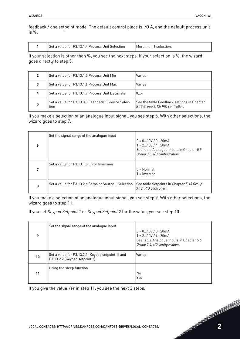
feedback / one setpoint mode. The default control place is I/O A, and the default process unitis %.
1 Set a value for P3.13.1.4 Process Unit Selection More than 1 selection.
If your selection is other than %, you see the next steps. If your selection is %, the wizardgoes directly to step 5.
2 Set a value for P3.13.1.5 Process Unit Min Varies
3 Set a value for P3.13.1.6 Process Unit Max Varies
4 Set a value for P3.13.1.7 Process Unit Decimals 0...4
5 Set a value for P3.13.3.3 Feedback 1 Source Selec-tion
See the table Feedback settings in Chapter5.13 Group 3.13: PID controller.
If you make a selection of an analogue input signal, you see step 6. With other selections, thewizard goes to step 7.
6
Set the signal range of the analogue input0 = 0…10V / 0…20mA1 = 2…10V / 4…20mASee table Analogue inputs in Chapter 5.5 Group 3.5: I/O configuration.
7Set a value for P3.13.1.8 Error Inversion
0 = Normal1 = Inverted
8 Set a value for P3.13.2.6 Setpoint Source 1 Selection See table Setpoints in Chapter 5.13 Group 3.13: PID controller.
If you make a selection of an analogue input signal, you see step 9. With other selections, thewizard goes to step 11.
If you set Keypad Setpoint 1 or Keypad Setpoint 2 for the value, you see step 10.
9
Set the signal range of the analogue input0 = 0…10V / 0…20mA1 = 2…10V / 4…20mASee table Analogue inputs in Chapter 5.5 Group 3.5: I/O configuration.
10 Set a value for P3.13.2.1 (Keypad setpoint 1) andP3.13.2.2 (Keypad setpoint 2)
Varies
11Using the sleep function
NoYes
If you give the value Yes in step 11, you see the next 3 steps.
WIZARDS VACON · 61
LOCAL CONTACTS: HTTP://DRIVES.DANFOSS.COM/DANFOSS-DRIVES/LOCAL-CONTACTS/ 2
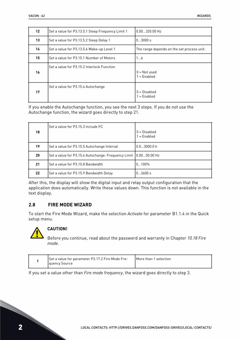
12 Set a value for P3.13.5.1 Sleep Frequency Limit 1 0.00...320.00 Hz
13 Set a value for P3.13.5.2 Sleep Delay 1 0...3000 s
14 Set a value for P3.13.5.6 Wake-up Level 1 The range depends on the set process unit.
15 Set a value for P3.15.1 Number of Motors 1...6
16Set a value for P3.15.2 Interlock Function
0 = Not used1 = Enabled
17Set a value for P3.15.4 Autochange
0 = Disabled1 = Enabled
If you enable the Autochange function, you see the next 3 steps. If you do not use theAutochange function, the wizard goes directly to step 21.
18Set a value for P3.15.3 Include FC
0 = Disabled1 = Enabled
19 Set a value for P3.15.5 Autochange Interval 0.0...3000.0 h
20 Set a value for P3.15.6 Autochange: Frequency Limit 0.00...50.00 Hz
21 Set a value for P3.15.8 Bandwidth 0...100%
22 Set a value for P3.15.9 Bandwidth Delay 0...3600 s
After this, the display will show the digital input and relay output configuration that theapplication does automatically. Write these values down. This function is not available in thetext display.
2.8 FIRE MODE WIZARD
To start the Fire Mode Wizard, make the selection Activate for parameter B1.1.4 in the Quicksetup menu.
CAUTION!
Before you continue, read about the password and warranty in Chapter 10.18 Fire mode.
1 Set a value for parameter P3.17.2 Fire Mode Fre-quency Source
More than 1 selection
If you set a value other than Fire mode frequency, the wizard goes directly to step 3.
VACON · 62 WIZARDS
2 LOCAL CONTACTS: HTTP://DRIVES.DANFOSS.COM/DANFOSS-DRIVES/LOCAL-CONTACTS/
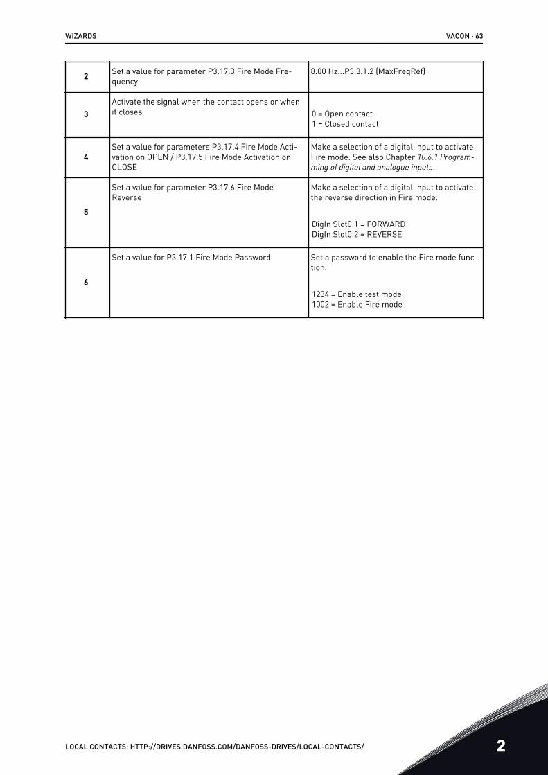
2 Set a value for parameter P3.17.3 Fire Mode Fre-quency
8.00 Hz...P3.3.1.2 (MaxFreqRef)
3Activate the signal when the contact opens or whenit closes 0 = Open contact
1 = Closed contact
4Set a value for parameters P3.17.4 Fire Mode Acti-vation on OPEN / P3.17.5 Fire Mode Activation onCLOSE
Make a selection of a digital input to activateFire mode. See also Chapter 10.6.1 Program-ming of digital and analogue inputs.
5
Set a value for parameter P3.17.6 Fire ModeReverse
Make a selection of a digital input to activatethe reverse direction in Fire mode.
DigIn Slot0.1 = FORWARDDigIn Slot0.2 = REVERSE
6
Set a value for P3.17.1 Fire Mode Password Set a password to enable the Fire mode func-tion.
1234 = Enable test mode1002 = Enable Fire mode
WIZARDS VACON · 63
LOCAL CONTACTS: HTTP://DRIVES.DANFOSS.COM/DANFOSS-DRIVES/LOCAL-CONTACTS/ 2

3 USER INTERFACES3.1 NAVIGATION ON THE KEYPAD
The data of the AC drive is in menus and submenus. To move between the menus, use thearrow buttons Up and Down in the keypad. To go into a group or an item, push the OK button.To go back to the level where you were before, push the Back/Reset button.
On the display, you see your current location in the menu, for example M3.2.1. You also seethe name of the group or item in your current location.
VACON · 64 USER INTERFACES
3 LOCAL CONTACTS: HTTP://DRIVES.DANFOSS.COM/DANFOSS-DRIVES/LOCAL-CONTACTS/
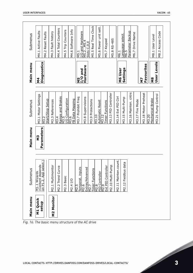
Mai
n m
enu
Sub
men
usSub
men
usSub
men
usM
ain
men
uM
ain
men
u
M2
Mon
itor
M1
Qu
ick
setu
pM
1.1
Wiz
ards
(C
onte
nt d
epen
ds
on P
1.2,
App
sel
ect.
)
M2.
1 M
ultim
onito
r
M3.
1 M
otor
Set
tings
M3.
2 Sta
rt/S
top
Set
up
M3.
3 Re
fere
nces
M3.
4 Ram
ps a
nd B
rake
sM
3.5
I/O
Con
figur
atio
nM
3.6
FB D
ata
Map
ping
M3.
10
Aut
omat
ic R
eset
M3.
12Ti
mer
Fun
ctio
ns
M3.
20
Mec
hani
cal B
rake
M3.
13 P
ID C
ontr
olle
r
M3.
14 E
xt P
ID C
trl
M3.
15 M
ulti-
Pum
p
M3.
16 M
aint
en.
cntr
s
M3.
17 F
ire
Mod
e
M3.
21 P
ump
Con
trol
M3.
18 M
otor
Pre
heat
M3.
7 Pr
ohib
it Fr
eq
M3.
8 Sup
ervi
sion
s
M3.
9 Pr
otec
tions
M2.
2 Tr
end
Cur
ve
M2.
3 Bas
ic
M2.
4 I/
O
M2.
5 Te
mpe
rat.
inpu
tsM
2.6
Extr
as/A
dvan
ced
M2.
7 Ti
mer
Fun
ctio
nsM
2.8
PID
Con
trol
ler
M2.
9 Ex
t PI
D C
ontr
olle
rM
2.10
Mul
ti-Pu
mp
M2.
11 M
aint
en.c
ount
.
M2.
12 F
ield
bus
data
M3
P
aram
eter
s
M8
U
ser
Leve
ls
M7
Fa
vou
rite
s
M4
Dia
gn
osti
cs
M5
I/
O a
nd
H
ard
war
e
M6
Use
r S
etti
ng
s
M4.
1 Act
ive
Faul
ts
M4.
2 Re
set
Faul
ts
M4.
3 Fa
ult
hist
ory
M4.
4 To
tal C
ount
ers
M4.
5 Tr
ip C
ount
ers
M4.
6 Sof
twar
e In
fo
M5.
1 I/
O a
nd H
ardw
are
M5.
2...
M5.
4 Slo
ts C
,D,E
M5.
5 Re
al T
ime
Clo
ck
M5.
6 Po
wer
uni
t se
tt.
M5.
7 Ke
ypad
M5.
8 RS-4
85
M6.
1 La
ngua
ge s
elec
t.M
6.5
Para
met
er B
acku
pM
6.7
Drive
Nam
e
M8.
1 U
ser
Leve
l
M8.
2 Acc
ess
Cod
e
Fig. 16: The basic menu structure of the AC drive
USER INTERFACES VACON · 65
LOCAL CONTACTS: HTTP://DRIVES.DANFOSS.COM/DANFOSS-DRIVES/LOCAL-CONTACTS/ 3
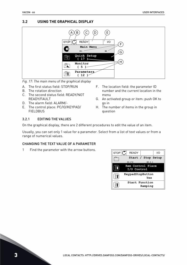
3.2 USING THE GRAPHICAL DISPLAY
STOP READY I/O
Main Menu
A B C D E
F
H
GQuick Setup( 17 )Monitor( 5 )
Parameters( 12 )
M1ID:
Fig. 17: The main menu of the graphical displayA. The first status field: STOP/RUNB. The rotation directionC. The second status field: READY/NOT
READY/FAULTD. The alarm field: ALARM/-E. The control place: PC/IO/KEYPAD/
FIELDBUS
F. The location field: the parameter IDnumber and the current location in themenu
G. An activated group or item: push OK togo in
H. The number of items in the group inquestion
3.2.1 EDITING THE VALUESOn the graphical display, there are 2 different procedures to edit the value of an item.
Usually, you can set only 1 value for a parameter. Select from a list of text values or from arange of numerical values.
CHANGING THE TEXT VALUE OF A PARAMETER1 Find the parameter with the arrow buttons.
STOP READY I/O
Rem Control PlaceI/O Control
KeypadStopButtonYes
Start FunctionRamping
Start / Stop SetupM3.2.1ID:172
VACON · 66 USER INTERFACES
3 LOCAL CONTACTS: HTTP://DRIVES.DANFOSS.COM/DANFOSS-DRIVES/LOCAL-CONTACTS/
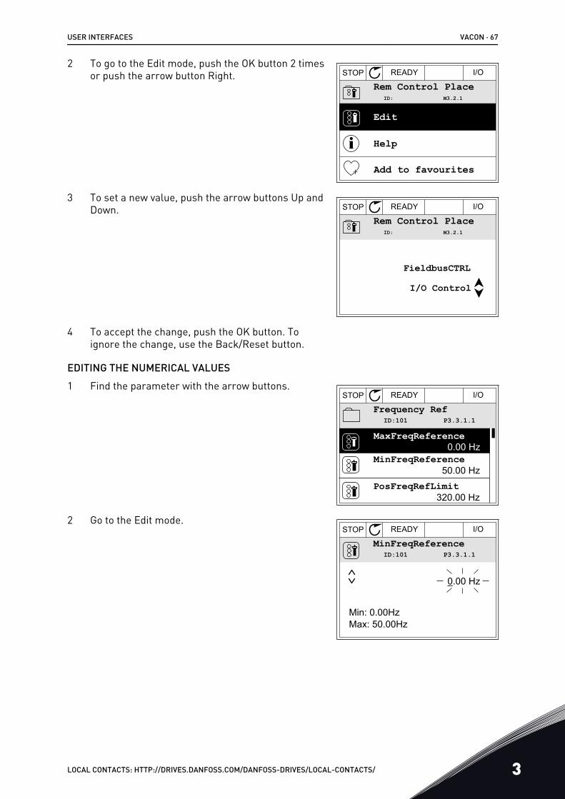
2 To go to the Edit mode, push the OK button 2 timesor push the arrow button Right. STOP READY I/O
Rem Control PlaceM3.2.1ID:
Edit
Help
Add to favourites
3 To set a new value, push the arrow buttons Up andDown. STOP READY I/O
Rem Control PlaceM3.2.1ID:
FieldbusCTRL
I/O Control
4 To accept the change, push the OK button. Toignore the change, use the Back/Reset button.
EDITING THE NUMERICAL VALUES1 Find the parameter with the arrow buttons.
STOP READY I/O
Frequency RefP3.3.1.1ID:101
MaxFreqReference0.00 Hz
MinFreqReference50.00 Hz
PosFreqRefLimit320.00 Hz
2 Go to the Edit mode.STOP READY I/O
MinFreqReferenceP3.3.1.1ID:101
0.00 Hz
Min: 0.00HzMax: 50.00Hz
USER INTERFACES VACON · 67
LOCAL CONTACTS: HTTP://DRIVES.DANFOSS.COM/DANFOSS-DRIVES/LOCAL-CONTACTS/ 3
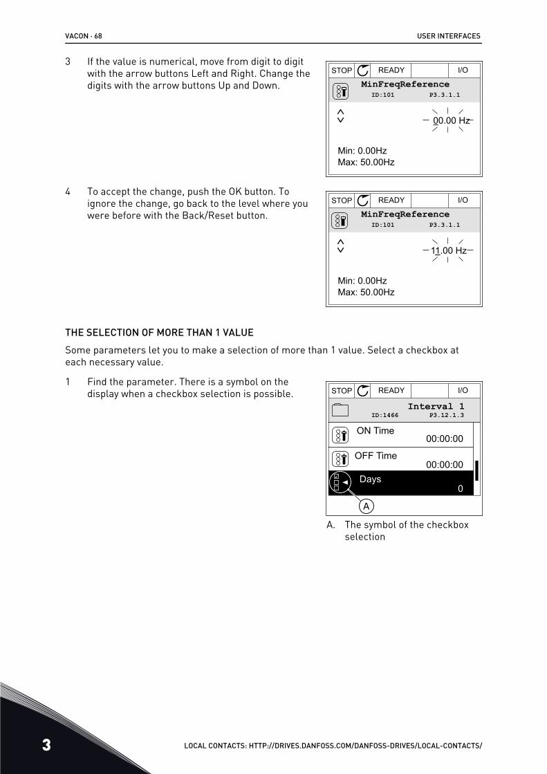
3 If the value is numerical, move from digit to digitwith the arrow buttons Left and Right. Change thedigits with the arrow buttons Up and Down.
STOP READY I/O
MinFreqReferenceP3.3.1.1ID:101
00.00 Hz
Min: 0.00HzMax: 50.00Hz
4 To accept the change, push the OK button. Toignore the change, go back to the level where youwere before with the Back/Reset button.
STOP READY I/O
MinFreqReferenceP3.3.1.1ID:101
11.00 Hz
Min: 0.00HzMax: 50.00Hz
THE SELECTION OF MORE THAN 1 VALUESome parameters let you to make a selection of more than 1 value. Select a checkbox ateach necessary value.
1 Find the parameter. There is a symbol on thedisplay when a checkbox selection is possible. STOP READY I/O
P3.12.1.3ID:1466Interval 1
00:00:00
00:00:00ON Time
OFF Time
Days0
A
A. The symbol of the checkboxselection
VACON · 68 USER INTERFACES
3 LOCAL CONTACTS: HTTP://DRIVES.DANFOSS.COM/DANFOSS-DRIVES/LOCAL-CONTACTS/
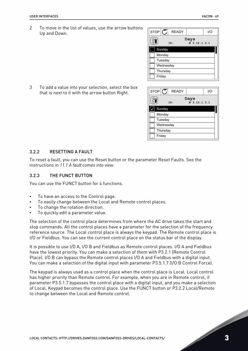
2 To move in the list of values, use the arrow buttonsUp and Down. STOP READY I/O
M 3.12.1.3.1ID:Days
MondayTuesdayWednesday
ThursdayFriday
Sunday
3 To add a value into your selection, select the boxthat is next to it with the arrow button Right. STOP READY I/O
M 3.12.1.3.1ID:Days
MondayTuesdayWednesday
ThursdayFriday
Sunday
3.2.2 RESETTING A FAULTTo reset a fault, you can use the Reset button or the parameter Reset Faults. See theinstructions in 11.1 A fault comes into view.
3.2.3 THE FUNCT BUTTONYou can use the FUNCT button for 4 functions.
• To have an access to the Control page.• To easily change between the Local and Remote control places.• To change the rotation direction.• To quickly edit a parameter value.
The selection of the control place determines from where the AC drive takes the start andstop commands. All the control places have a parameter for the selection of the frequencyreference source. The Local control place is always the keypad. The Remote control place isI/O or Fieldbus. You can see the current control place on the status bar of the display.
It is possible to use I/O A, I/O B and Fieldbus as Remote control places. I/O A and Fieldbushave the lowest priority. You can make a selection of them with P3.2.1 (Remote ControlPlace). I/O B can bypass the Remote control places I/O A and Fieldbus with a digital input.You can make a selection of the digital input with parameter P3.5.1.7 (I/O B Control Force).
The keypad is always used as a control place when the control place is Local. Local controlhas higher priority than Remote control. For example, when you are in Remote control, ifparameter P3.5.1.7 bypasses the control place with a digital input, and you make a selectionof Local, Keypad becomes the control place. Use the FUNCT button or P3.2.2 Local/Remoteto change between the Local and Remote control.
USER INTERFACES VACON · 69
LOCAL CONTACTS: HTTP://DRIVES.DANFOSS.COM/DANFOSS-DRIVES/LOCAL-CONTACTS/ 3
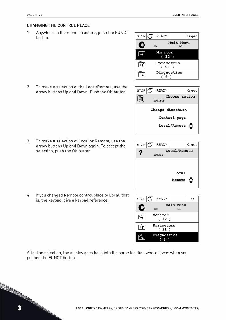
CHANGING THE CONTROL PLACE1 Anywhere in the menu structure, push the FUNCT
button. STOP READY Keypad
ID: M1Main Menu
Monitor( 12 )
( 21 )
( 6 )
Parameters
Diagnostics
2 To make a selection of the Local/Remote, use thearrow buttons Up and Down. Push the OK button. STOP READY Keypad
ID:1805Choose action
Control page
Change direction
Local/Remote
3 To make a selection of Local or Remote, use thearrow buttons Up and Down again. To accept theselection, push the OK button.
STOP READY Keypad
ID:211Local/Remote
RemoteLocal
4 If you changed Remote control place to Local, thatis, the keypad, give a keypad reference. STOP READY I/O
ID: M1Main Menu
( 21 )
( 6 )
Parameters( 12 )
Monitor
Diagnostics
After the selection, the display goes back into the same location where it was when youpushed the FUNCT button.
VACON · 70 USER INTERFACES
3 LOCAL CONTACTS: HTTP://DRIVES.DANFOSS.COM/DANFOSS-DRIVES/LOCAL-CONTACTS/
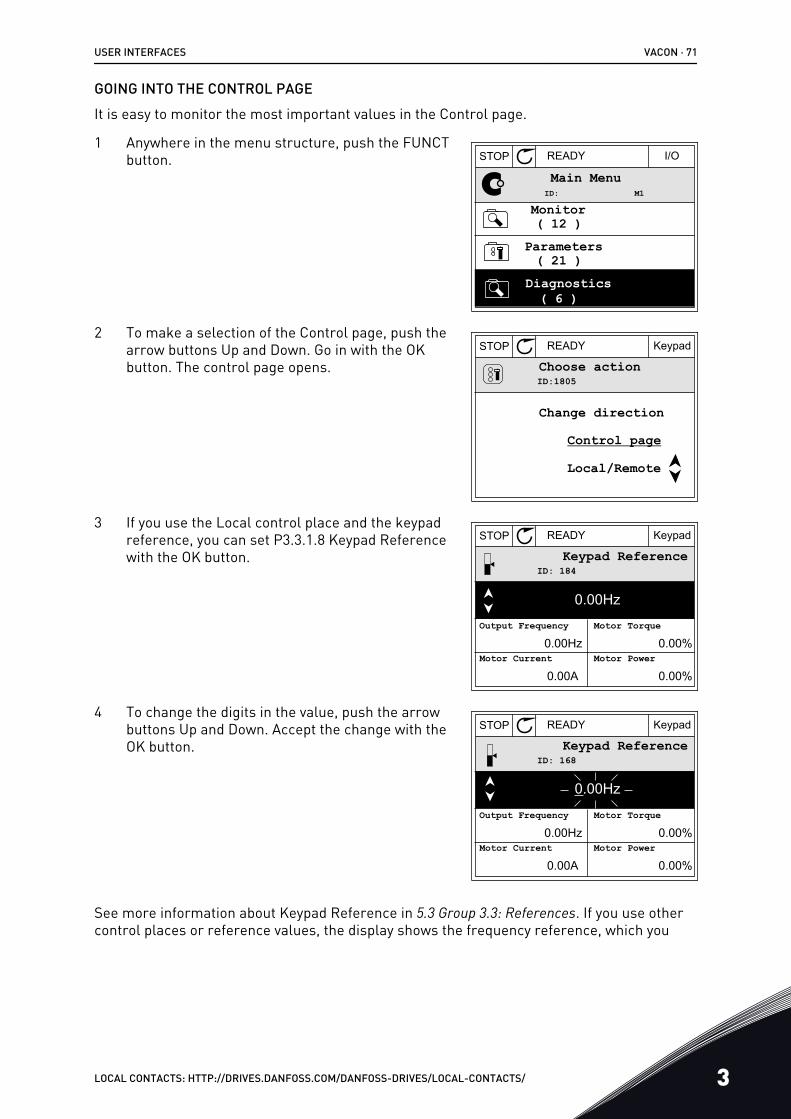
GOING INTO THE CONTROL PAGEIt is easy to monitor the most important values in the Control page.
1 Anywhere in the menu structure, push the FUNCTbutton. STOP READY I/O
Main Menu
( 21 )
( 6 )
Parameters( 12 )Monitor
Diagnostics
M1ID:
2 To make a selection of the Control page, push thearrow buttons Up and Down. Go in with the OKbutton. The control page opens.
STOP READY Keypad
ID:1805 Choose action
Control page
Change direction
Local/Remote
3 If you use the Local control place and the keypadreference, you can set P3.3.1.8 Keypad Referencewith the OK button.
STOP READY Keypad
ID: 184Keypad Reference
0.00Hz
Output Frequency
Motor Current
Motor Torque
Motor Power0.00Hz
0.00A
0.00%
0.00%
4 To change the digits in the value, push the arrowbuttons Up and Down. Accept the change with theOK button.
STOP READY Keypad
ID: 168Keypad Reference
0.00Hz
Output Frequency
Motor Current
Motor Torque
Motor Power0.00Hz
0.00A
0.00%
0.00%
See more information about Keypad Reference in 5.3 Group 3.3: References. If you use othercontrol places or reference values, the display shows the frequency reference, which you
USER INTERFACES VACON · 71
LOCAL CONTACTS: HTTP://DRIVES.DANFOSS.COM/DANFOSS-DRIVES/LOCAL-CONTACTS/ 3
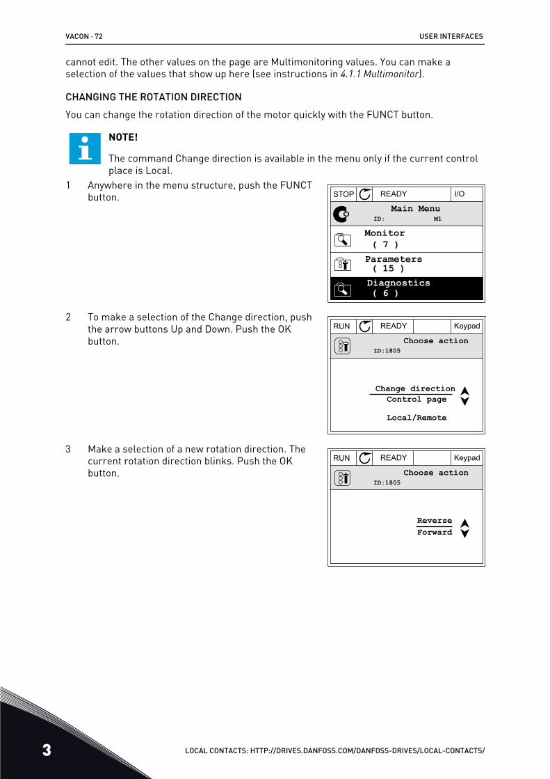
cannot edit. The other values on the page are Multimonitoring values. You can make aselection of the values that show up here (see instructions in 4.1.1 Multimonitor).
CHANGING THE ROTATION DIRECTIONYou can change the rotation direction of the motor quickly with the FUNCT button.
NOTE!
The command Change direction is available in the menu only if the current controlplace is Local.
1 Anywhere in the menu structure, push the FUNCTbutton. STOP READY I/O
ID: M1Main Menu
Monitor( 7 )
Parameters( 15 )Diagnostics( 6 )
2 To make a selection of the Change direction, pushthe arrow buttons Up and Down. Push the OKbutton.
RUN READY Keypad
ID:1805Choose action
Control pageChange direction
Local/Remote
3 Make a selection of a new rotation direction. Thecurrent rotation direction blinks. Push the OKbutton.
RUN READY Keypad
ID:1805Choose action
ForwardReverse
VACON · 72 USER INTERFACES
3 LOCAL CONTACTS: HTTP://DRIVES.DANFOSS.COM/DANFOSS-DRIVES/LOCAL-CONTACTS/
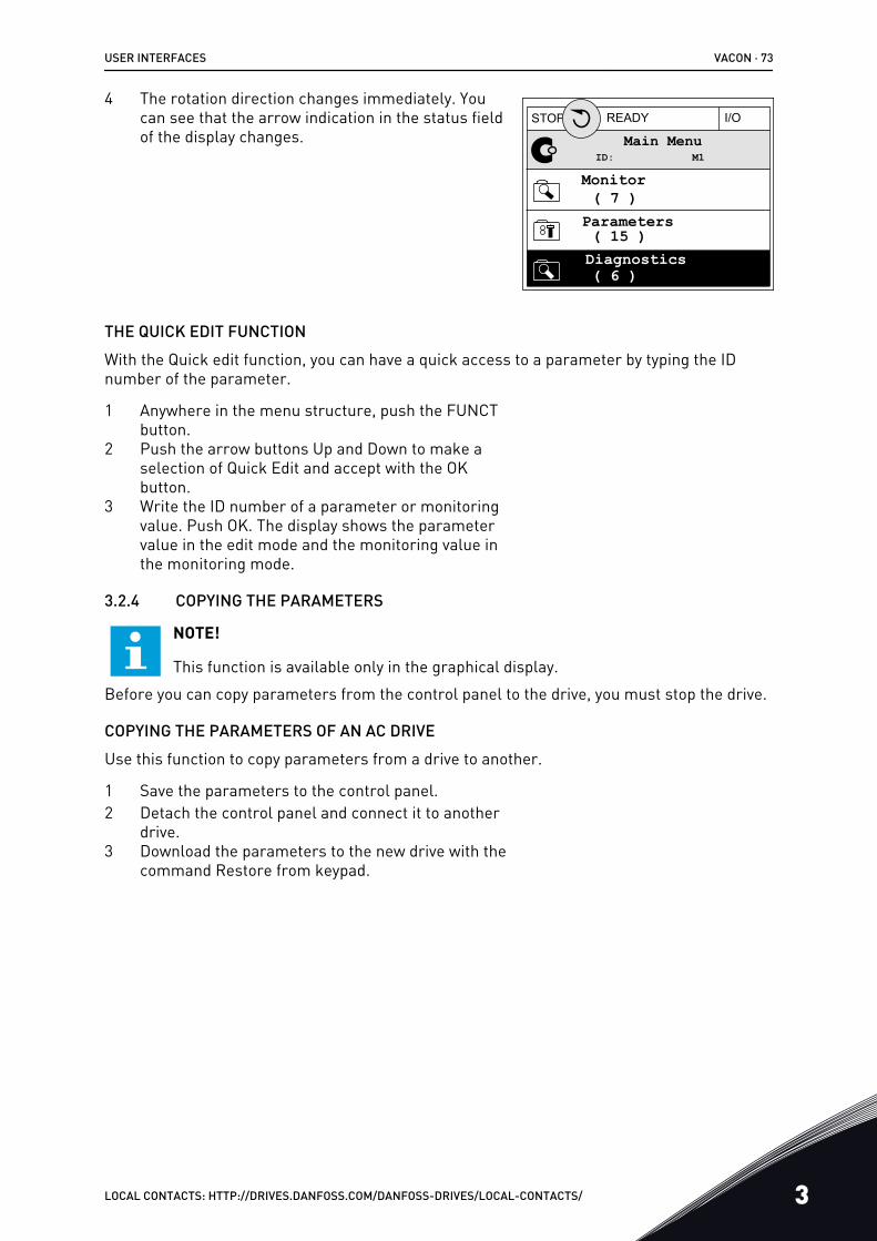
4 The rotation direction changes immediately. Youcan see that the arrow indication in the status fieldof the display changes.
STOP READY I/O
ID: M1Main Menu
Monitor( 7 )
Parameters( 15 )Diagnostics( 6 )
THE QUICK EDIT FUNCTIONWith the Quick edit function, you can have a quick access to a parameter by typing the IDnumber of the parameter.
1 Anywhere in the menu structure, push the FUNCTbutton.
2 Push the arrow buttons Up and Down to make aselection of Quick Edit and accept with the OKbutton.
3 Write the ID number of a parameter or monitoringvalue. Push OK. The display shows the parametervalue in the edit mode and the monitoring value inthe monitoring mode.
3.2.4 COPYING THE PARAMETERS
NOTE!
This function is available only in the graphical display.Before you can copy parameters from the control panel to the drive, you must stop the drive.
COPYING THE PARAMETERS OF AN AC DRIVEUse this function to copy parameters from a drive to another.
1 Save the parameters to the control panel.2 Detach the control panel and connect it to another
drive.3 Download the parameters to the new drive with the
command Restore from keypad.
USER INTERFACES VACON · 73
LOCAL CONTACTS: HTTP://DRIVES.DANFOSS.COM/DANFOSS-DRIVES/LOCAL-CONTACTS/ 3
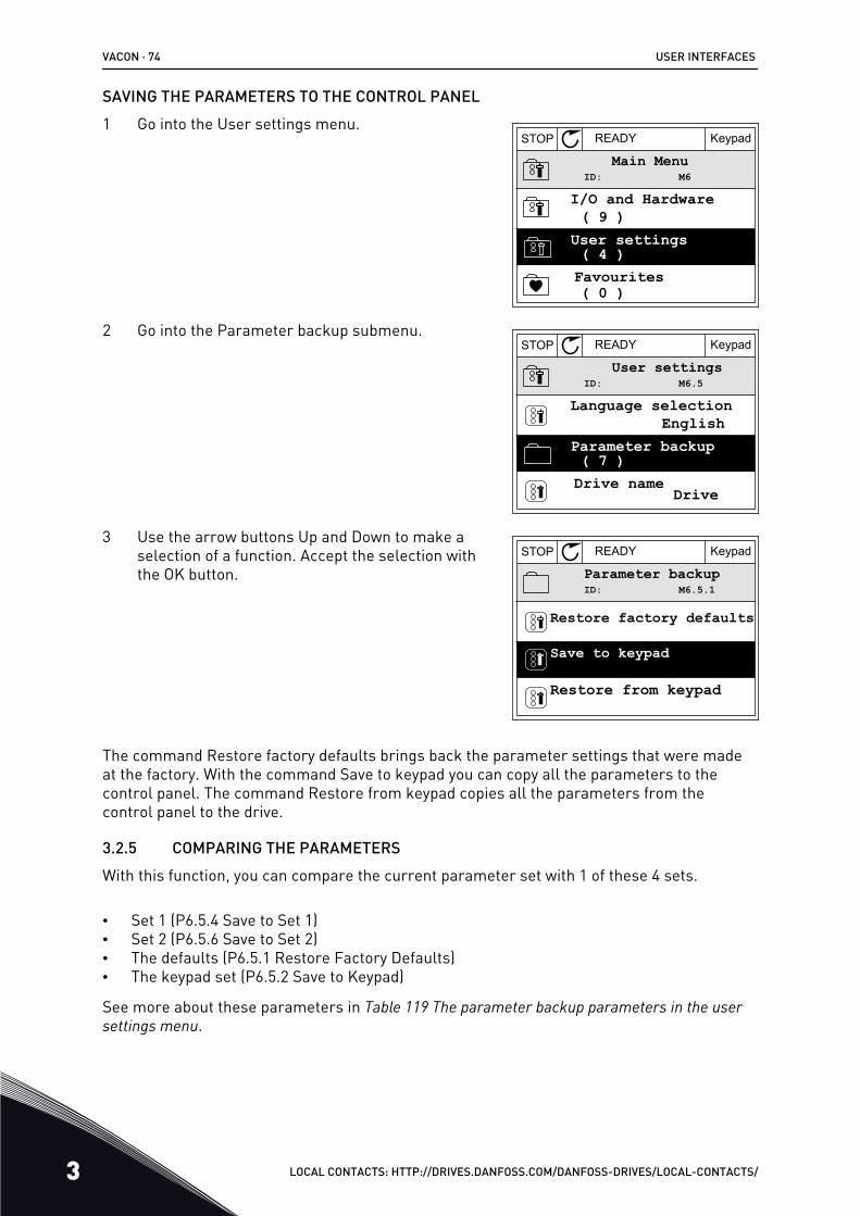
SAVING THE PARAMETERS TO THE CONTROL PANEL1 Go into the User settings menu.
STOP READY Keypad
ID: M6Main Menu
I/O and Hardware( 9 )
User settings( 4 )Favourites( 0 )
2 Go into the Parameter backup submenu.STOP READY Keypad
ID: M6.5User settings
Language selectionEnglish
Parameter backup( 7 )Drive name Drive
3 Use the arrow buttons Up and Down to make aselection of a function. Accept the selection withthe OK button.
STOP READY Keypad
ID: M6.5.1Parameter backup
Restore factory defaults
Save to keypad
Restore from keypad
The command Restore factory defaults brings back the parameter settings that were madeat the factory. With the command Save to keypad you can copy all the parameters to thecontrol panel. The command Restore from keypad copies all the parameters from thecontrol panel to the drive.
3.2.5 COMPARING THE PARAMETERSWith this function, you can compare the current parameter set with 1 of these 4 sets.
• Set 1 (P6.5.4 Save to Set 1)• Set 2 (P6.5.6 Save to Set 2)• The defaults (P6.5.1 Restore Factory Defaults)• The keypad set (P6.5.2 Save to Keypad)
See more about these parameters in Table 119 The parameter backup parameters in the user settings menu.
VACON · 74 USER INTERFACES
3 LOCAL CONTACTS: HTTP://DRIVES.DANFOSS.COM/DANFOSS-DRIVES/LOCAL-CONTACTS/
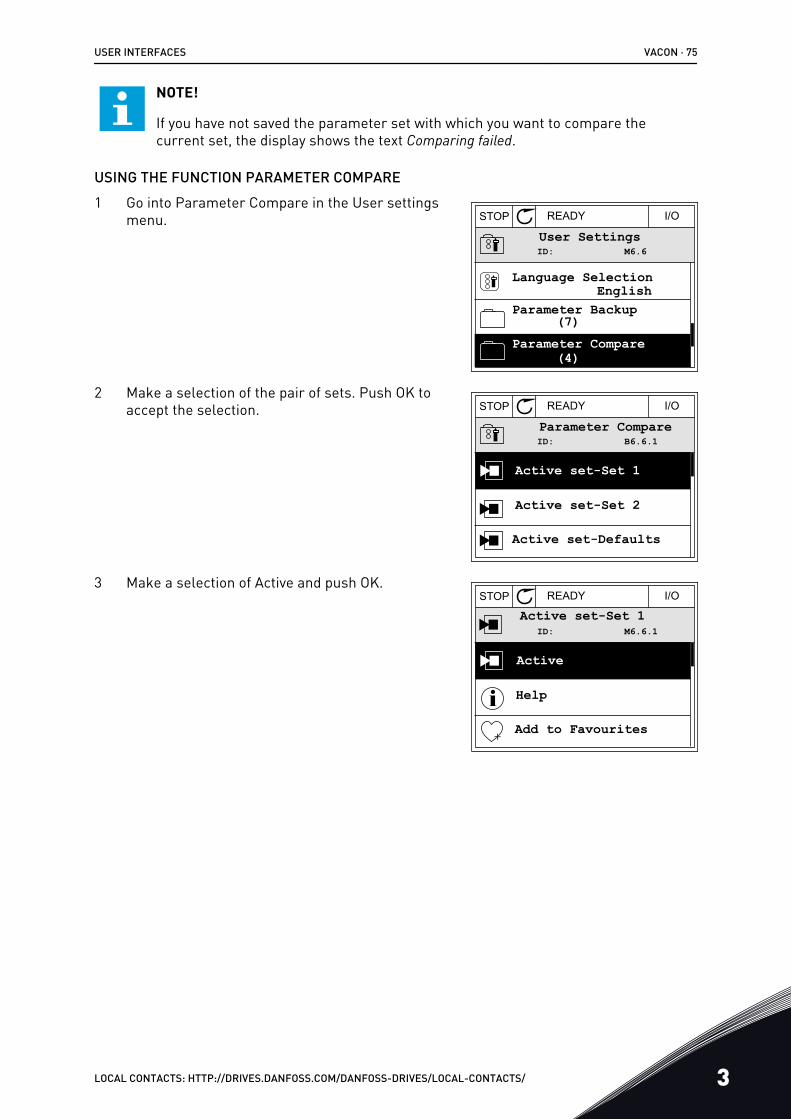
NOTE!
If you have not saved the parameter set with which you want to compare thecurrent set, the display shows the text Comparing failed.
USING THE FUNCTION PARAMETER COMPARE1 Go into Parameter Compare in the User settings
menu. STOP READY I/O
ID: M6.6User Settings
Language Selection
Parameter Backup
Parameter Compare
English
(4)
(7)
2 Make a selection of the pair of sets. Push OK toaccept the selection. STOP READY I/O
ID: B6.6.1Parameter Compare
Active set-Set 1
Active set-Set 2
Active set-Defaults
3 Make a selection of Active and push OK.STOP READY I/O
ID: M6.6.1Active set-Set 1
Active
Help
Add to Favourites
USER INTERFACES VACON · 75
LOCAL CONTACTS: HTTP://DRIVES.DANFOSS.COM/DANFOSS-DRIVES/LOCAL-CONTACTS/ 3
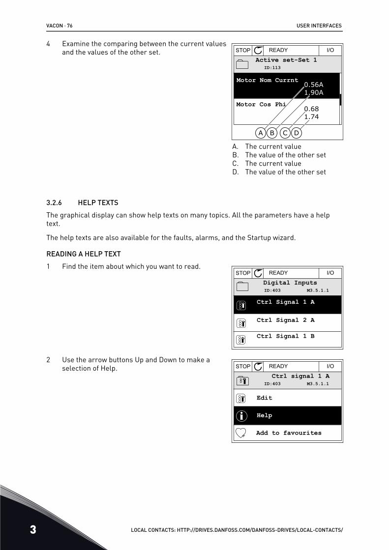
4 Examine the comparing between the current valuesand the values of the other set. STOP READY I/O
ID:113Active set-Set 1
Motor Nom Currnt
Motor Cos Phi
0.56A1.90A
0.681.74
A B C D
A. The current valueB. The value of the other setC. The current valueD. The value of the other set
3.2.6 HELP TEXTSThe graphical display can show help texts on many topics. All the parameters have a helptext.
The help texts are also available for the faults, alarms, and the Startup wizard.
READING A HELP TEXT1 Find the item about which you want to read.
STOP READY I/O
ID:403 M3.5.1.1Digital Inputs
Ctrl Signal 1 A
Ctrl Signal 2 A
Ctrl Signal 1 B
2 Use the arrow buttons Up and Down to make aselection of Help. STOP READY I/O
ID:403 M3.5.1.1Ctrl signal 1 A
Edit
Help
Add to favourites
VACON · 76 USER INTERFACES
3 LOCAL CONTACTS: HTTP://DRIVES.DANFOSS.COM/DANFOSS-DRIVES/LOCAL-CONTACTS/
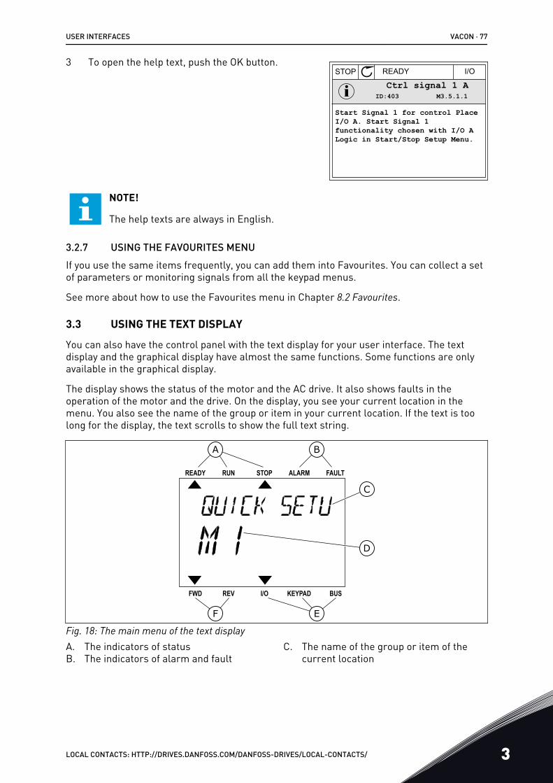
3 To open the help text, push the OK button.STOP READY I/O
ID:403 M3.5.1.1Ctrl signal 1 A
Start Signal 1 for control Place I/O A. Start Signal 1functionality chosen with I/O ALogic in Start/Stop Setup Menu.
NOTE!
The help texts are always in English.
3.2.7 USING THE FAVOURITES MENUIf you use the same items frequently, you can add them into Favourites. You can collect a setof parameters or monitoring signals from all the keypad menus.
See more about how to use the Favourites menu in Chapter 8.2 Favourites.
3.3 USING THE TEXT DISPLAY
You can also have the control panel with the text display for your user interface. The textdisplay and the graphical display have almost the same functions. Some functions are onlyavailable in the graphical display.
The display shows the status of the motor and the AC drive. It also shows faults in theoperation of the motor and the drive. On the display, you see your current location in themenu. You also see the name of the group or item in your current location. If the text is toolong for the display, the text scrolls to show the full text string.
A B
F
C
D
E
Fig. 18: The main menu of the text displayA. The indicators of statusB. The indicators of alarm and fault
C. The name of the group or item of thecurrent location
USER INTERFACES VACON · 77
LOCAL CONTACTS: HTTP://DRIVES.DANFOSS.COM/DANFOSS-DRIVES/LOCAL-CONTACTS/ 3
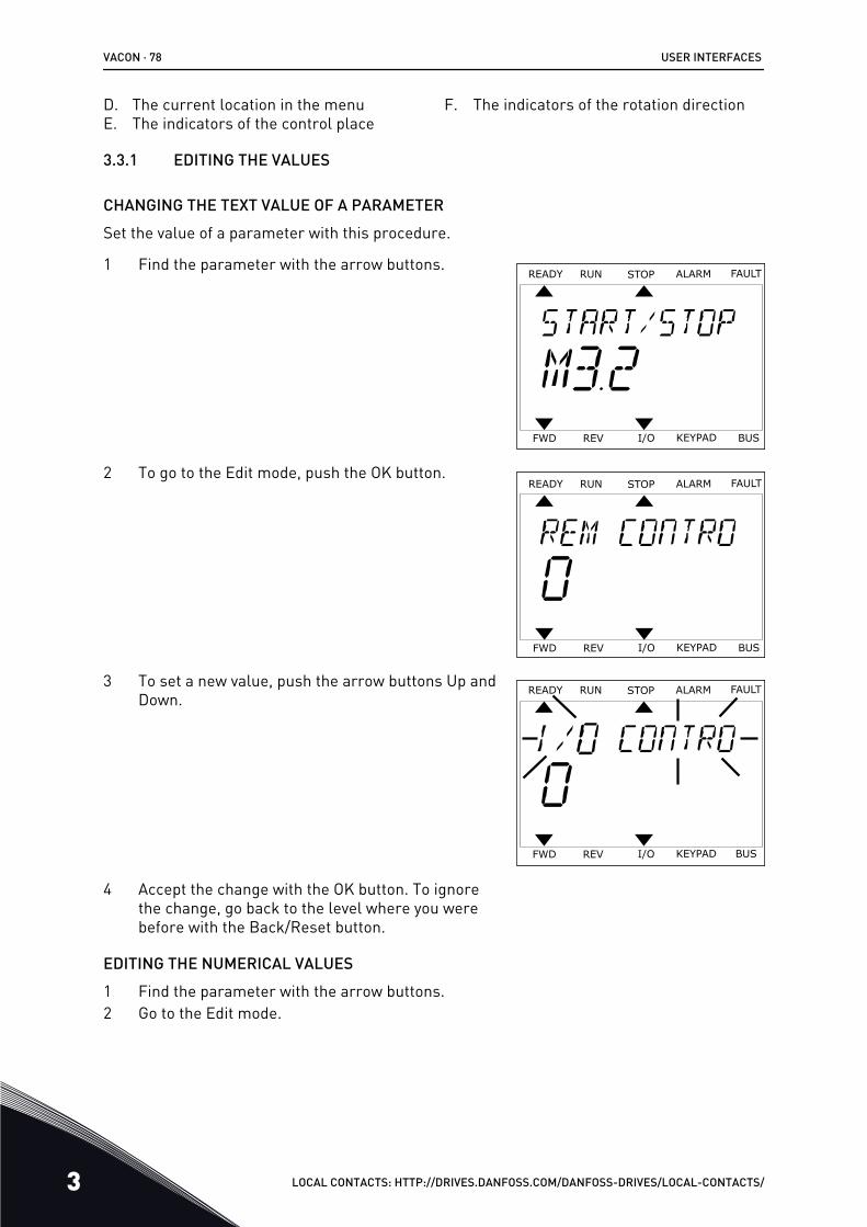
D. The current location in the menuE. The indicators of the control place
F. The indicators of the rotation direction
3.3.1 EDITING THE VALUES
CHANGING THE TEXT VALUE OF A PARAMETERSet the value of a parameter with this procedure.
1 Find the parameter with the arrow buttons.READY FAULTALARMSTOPRUN
BUSKEYPADI/OREVFWD
2 To go to the Edit mode, push the OK button.READY FAULTALARMSTOPRUN
BUSKEYPADI/OREVFWD
3 To set a new value, push the arrow buttons Up andDown.
READY FAULTALARMSTOPRUN
KEYPADI/OREVFWD BUS
4 Accept the change with the OK button. To ignorethe change, go back to the level where you werebefore with the Back/Reset button.
EDITING THE NUMERICAL VALUES1 Find the parameter with the arrow buttons.2 Go to the Edit mode.
VACON · 78 USER INTERFACES
3 LOCAL CONTACTS: HTTP://DRIVES.DANFOSS.COM/DANFOSS-DRIVES/LOCAL-CONTACTS/
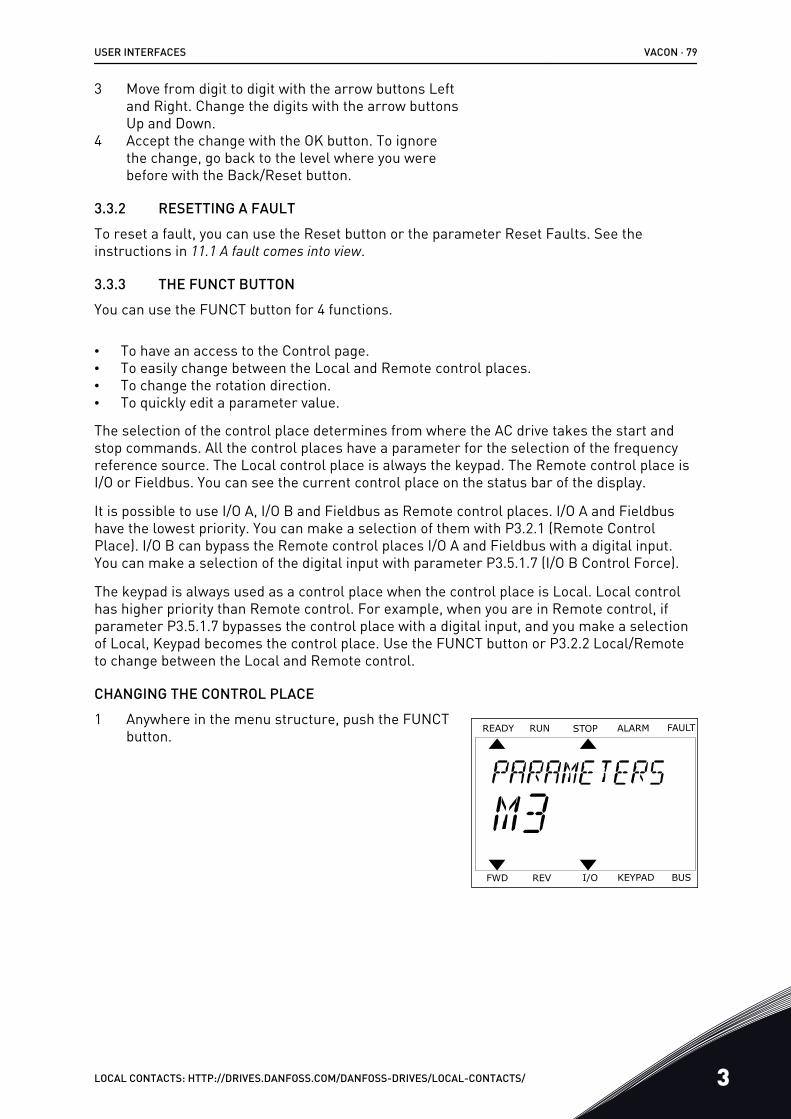
3 Move from digit to digit with the arrow buttons Leftand Right. Change the digits with the arrow buttonsUp and Down.
4 Accept the change with the OK button. To ignorethe change, go back to the level where you werebefore with the Back/Reset button.
3.3.2 RESETTING A FAULTTo reset a fault, you can use the Reset button or the parameter Reset Faults. See theinstructions in 11.1 A fault comes into view.
3.3.3 THE FUNCT BUTTONYou can use the FUNCT button for 4 functions.
• To have an access to the Control page.• To easily change between the Local and Remote control places.• To change the rotation direction.• To quickly edit a parameter value.
The selection of the control place determines from where the AC drive takes the start andstop commands. All the control places have a parameter for the selection of the frequencyreference source. The Local control place is always the keypad. The Remote control place isI/O or Fieldbus. You can see the current control place on the status bar of the display.
It is possible to use I/O A, I/O B and Fieldbus as Remote control places. I/O A and Fieldbushave the lowest priority. You can make a selection of them with P3.2.1 (Remote ControlPlace). I/O B can bypass the Remote control places I/O A and Fieldbus with a digital input.You can make a selection of the digital input with parameter P3.5.1.7 (I/O B Control Force).
The keypad is always used as a control place when the control place is Local. Local controlhas higher priority than Remote control. For example, when you are in Remote control, ifparameter P3.5.1.7 bypasses the control place with a digital input, and you make a selectionof Local, Keypad becomes the control place. Use the FUNCT button or P3.2.2 Local/Remoteto change between the Local and Remote control.
CHANGING THE CONTROL PLACE1 Anywhere in the menu structure, push the FUNCT
button. READY FAULTALARMSTOPRUN
KEYPADI/OREVFWD BUS
USER INTERFACES VACON · 79
LOCAL CONTACTS: HTTP://DRIVES.DANFOSS.COM/DANFOSS-DRIVES/LOCAL-CONTACTS/ 3
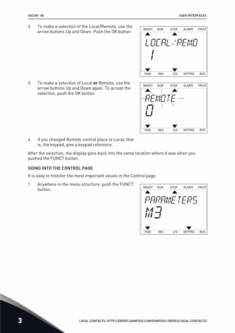
2 To make a selection of the Local/Remote, use thearrow buttons Up and Down. Push the OK button. READY FAULTALARMSTOPRUN
KEYPADI/OREVFWD BUS
3 To make a selection of Local or Remote, use thearrow buttons Up and Down again. To accept theselection, push the OK button.
READY FAULTALARMSTOPRUN
KEYPADI/OREVFWD BUS
4 If you changed Remote control place to Local, thatis, the keypad, give a keypad reference.
After the selection, the display goes back into the same location where it was when youpushed the FUNCT button.
GOING INTO THE CONTROL PAGEIt is easy to monitor the most important values in the Control page.
1 Anywhere in the menu structure, push the FUNCTbutton. READY FAULTALARMSTOPRUN
KEYPADI/OREVFWD BUS
VACON · 80 USER INTERFACES
3 LOCAL CONTACTS: HTTP://DRIVES.DANFOSS.COM/DANFOSS-DRIVES/LOCAL-CONTACTS/
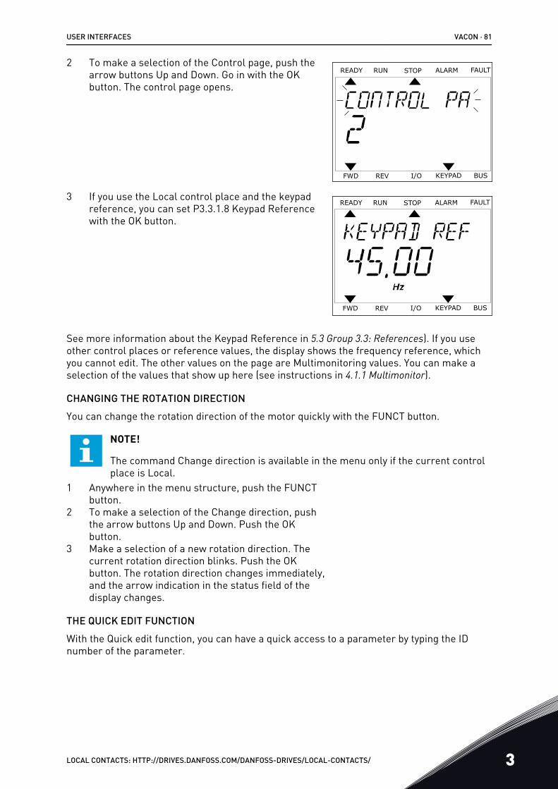
2 To make a selection of the Control page, push thearrow buttons Up and Down. Go in with the OKbutton. The control page opens.
READY FAULTALARMSTOPRUN
KEYPADI/OREVFWD BUS
3 If you use the Local control place and the keypadreference, you can set P3.3.1.8 Keypad Referencewith the OK button.
READY FAULTALARMSTOPRUN
KEYPADI/OREVFWD BUS
See more information about the Keypad Reference in 5.3 Group 3.3: References). If you useother control places or reference values, the display shows the frequency reference, whichyou cannot edit. The other values on the page are Multimonitoring values. You can make aselection of the values that show up here (see instructions in 4.1.1 Multimonitor).
CHANGING THE ROTATION DIRECTIONYou can change the rotation direction of the motor quickly with the FUNCT button.
NOTE!
The command Change direction is available in the menu only if the current controlplace is Local.
1 Anywhere in the menu structure, push the FUNCTbutton.
2 To make a selection of the Change direction, pushthe arrow buttons Up and Down. Push the OKbutton.
3 Make a selection of a new rotation direction. Thecurrent rotation direction blinks. Push the OKbutton. The rotation direction changes immediately,and the arrow indication in the status field of thedisplay changes.
THE QUICK EDIT FUNCTIONWith the Quick edit function, you can have a quick access to a parameter by typing the IDnumber of the parameter.
USER INTERFACES VACON · 81
LOCAL CONTACTS: HTTP://DRIVES.DANFOSS.COM/DANFOSS-DRIVES/LOCAL-CONTACTS/ 3

1 Anywhere in the menu structure, push the FUNCTbutton.
2 Push the arrow buttons Up and Down to make aselection of Quick Edit and accept with the OKbutton.
3 Write the ID number of a parameter or monitoringvalue. Push OK. The display shows the parametervalue in the edit mode and the monitoring value inthe monitoring mode.
VACON · 82 USER INTERFACES
3 LOCAL CONTACTS: HTTP://DRIVES.DANFOSS.COM/DANFOSS-DRIVES/LOCAL-CONTACTS/
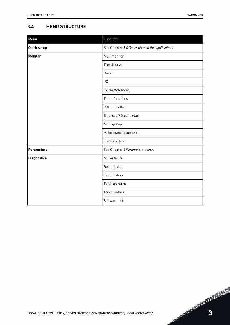
3.4 MENU STRUCTURE
Menu Function
Quick setup See Chapter 1.4 Description of the applications.
Monitor Multimonitor
Trend curve
Basic
I/O
Extras/Advanced
Timer functions
PID controller
External PID controller
Multi-pump
Maintenance counters
Fieldbus data
Parameters See Chapter 5 Parameters menu.
Diagnostics Active faults
Reset faults
Fault history
Total counters
Trip counters
Software info
USER INTERFACES VACON · 83
LOCAL CONTACTS: HTTP://DRIVES.DANFOSS.COM/DANFOSS-DRIVES/LOCAL-CONTACTS/ 3
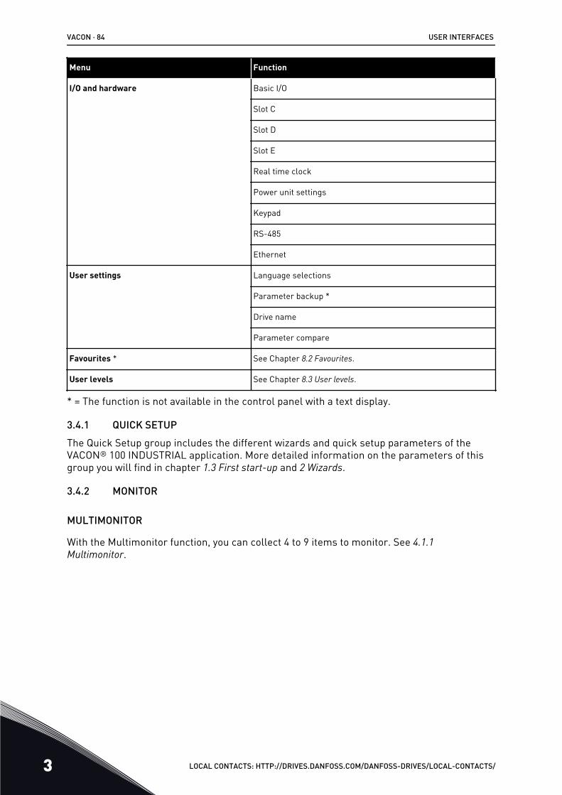
Menu Function
I/O and hardware Basic I/O
Slot C
Slot D
Slot E
Real time clock
Power unit settings
Keypad
RS-485
Ethernet
User settings Language selections
Parameter backup *
Drive name
Parameter compare
Favourites * See Chapter 8.2 Favourites.
User levels See Chapter 8.3 User levels.
* = The function is not available in the control panel with a text display.
3.4.1 QUICK SETUPThe Quick Setup group includes the different wizards and quick setup parameters of theVACON® 100 INDUSTRIAL application. More detailed information on the parameters of thisgroup you will find in chapter 1.3 First start-up and 2 Wizards.
3.4.2 MONITOR
MULTIMONITOR
With the Multimonitor function, you can collect 4 to 9 items to monitor. See 4.1.1 Multimonitor.
VACON · 84 USER INTERFACES
3 LOCAL CONTACTS: HTTP://DRIVES.DANFOSS.COM/DANFOSS-DRIVES/LOCAL-CONTACTS/
NOTE!
The Multimonitor menu is not available in the text display.
TREND CURVE
The Trend Curve function is a graphical presentation of 2 monitor values at the same time.See 4.1.2 Trend curve.
BASIC
The basic monitoring values can include statuses, measurements, and the actual values ofparameters and signals. See 4.1.3 Basic.
I/O
It is possible to monitor the statuses and levels of the values of input and output signals. See4.1.4 I/O.
EXTRAS/ADVANCED
You can monitor different advanced values, for example fieldbus values. See 4.1.6 Extras and advanced.
TIMER FUNCTIONS
With this function, you can monitor the timer functions and the Real Time Clock. See 4.1.7 Timer functions monitoring.
PID CONTROLLER
With this function, you can monitor the PID controller values. See 4.1.8 PID controller monitoring.
EXTERNAL PID CONTROLLER
Monitor the values that are related to the external PID controller. See 4.1.9 External PID controller monitoring.
MULTI-PUMP
Use this function to monitor the values that are related to the operation of more than 1 drive.See 4.1.10 Multi-pump monitoring.
MAINTENANCE COUNTERS
Monitor the values related to the maintenance counters. See 4.1.11 Maintenance counters.
FIELDBUS DATA
With this function, you see the fieldbus data as monitor values. Use this function, forexample, for monitoring during the fieldbus commissioning. See 4.1.12 Fieldbus process data monitoring.
USER INTERFACES VACON · 85
LOCAL CONTACTS: HTTP://DRIVES.DANFOSS.COM/DANFOSS-DRIVES/LOCAL-CONTACTS/ 3
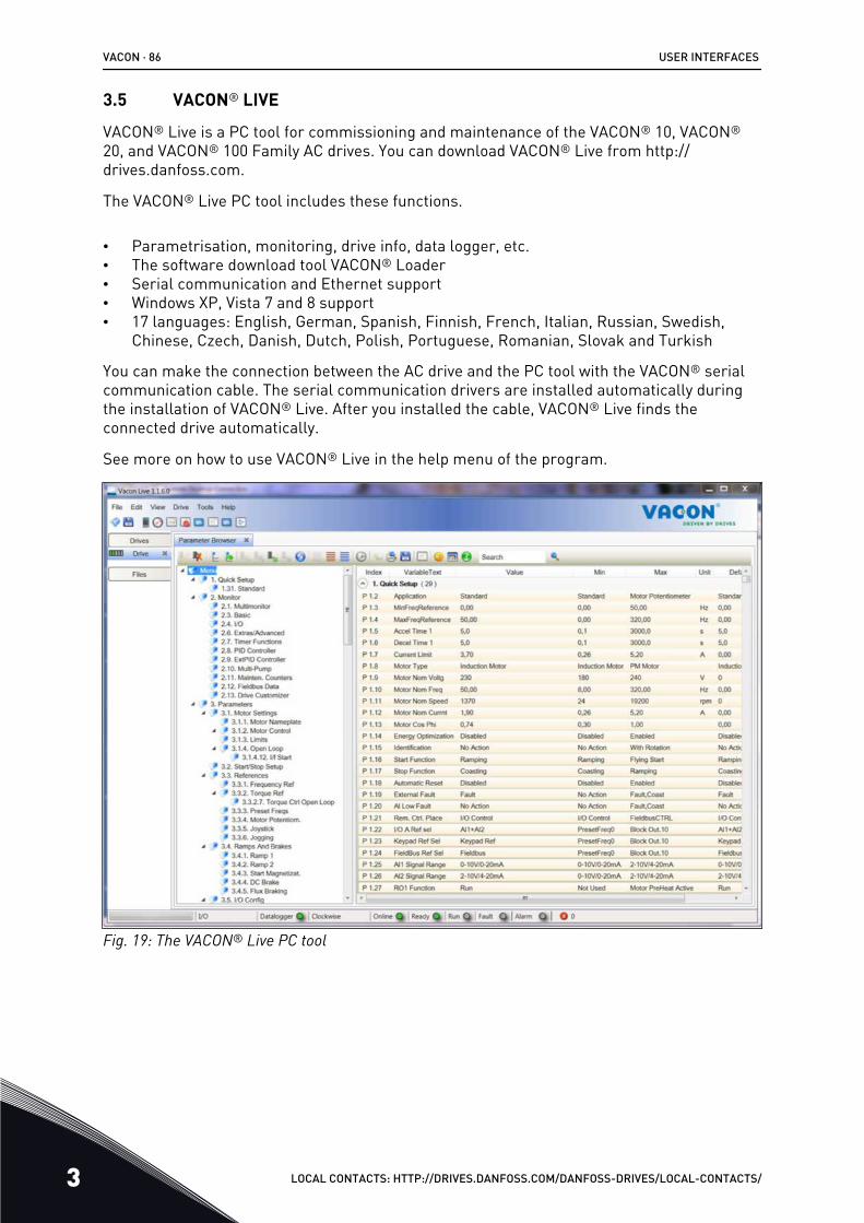
3.5 VACON® LIVE
VACON® Live is a PC tool for commissioning and maintenance of the VACON® 10, VACON®
20, and VACON® 100 Family AC drives. You can download VACON® Live from http://drives.danfoss.com.
The VACON® Live PC tool includes these functions.
• Parametrisation, monitoring, drive info, data logger, etc.• The software download tool VACON® Loader• Serial communication and Ethernet support• Windows XP, Vista 7 and 8 support• 17 languages: English, German, Spanish, Finnish, French, Italian, Russian, Swedish,
Chinese, Czech, Danish, Dutch, Polish, Portuguese, Romanian, Slovak and Turkish
You can make the connection between the AC drive and the PC tool with the VACON® serialcommunication cable. The serial communication drivers are installed automatically duringthe installation of VACON® Live. After you installed the cable, VACON® Live finds theconnected drive automatically.
See more on how to use VACON® Live in the help menu of the program.
Fig. 19: The VACON® Live PC tool
VACON · 86 USER INTERFACES
3 LOCAL CONTACTS: HTTP://DRIVES.DANFOSS.COM/DANFOSS-DRIVES/LOCAL-CONTACTS/
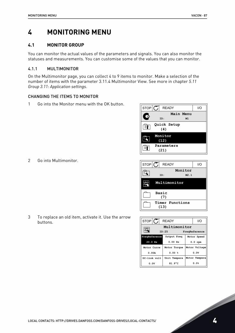
4 MONITORING MENU4.1 MONITOR GROUP
You can monitor the actual values of the parameters and signals. You can also monitor thestatuses and measurements. You can customise some of the values that you can monitor.
4.1.1 MULTIMONITOROn the Multimonitor page, you can collect 4 to 9 items to monitor. Make a selection of thenumber of items with the parameter 3.11.4 Multimonitor View. See more in chapter 5.11 Group 3.11: Application settings.
CHANGING THE ITEMS TO MONITOR1 Go into the Monitor menu with the OK button.
STOP READY I/O
ID: M1Main Menu
Monitor(12)
Quick Setup(4)
Parameters(21)
2 Go into Multimonitor.STOP READY I/O
ID: M2.1Monitor
Multimonitor
Timer Functions
Basic
(13)
(7)
3 To replace an old item, activate it. Use the arrowbuttons. STOP READY I/O
ID:25 FreqReferenceMultimonitor
20.0 Hz
Motor Curre
0.00ADC-link volt
0.0V
Output Freq
0.00 HzMotor Speed
0.0 rpmMotor Voltage
0.0VMotor Tempera
0.0%
Motor Torque
0.00 %Unit Tempera
81.9°C
FreqReference
MONITORING MENU VACON · 87
LOCAL CONTACTS: HTTP://DRIVES.DANFOSS.COM/DANFOSS-DRIVES/LOCAL-CONTACTS/ 4
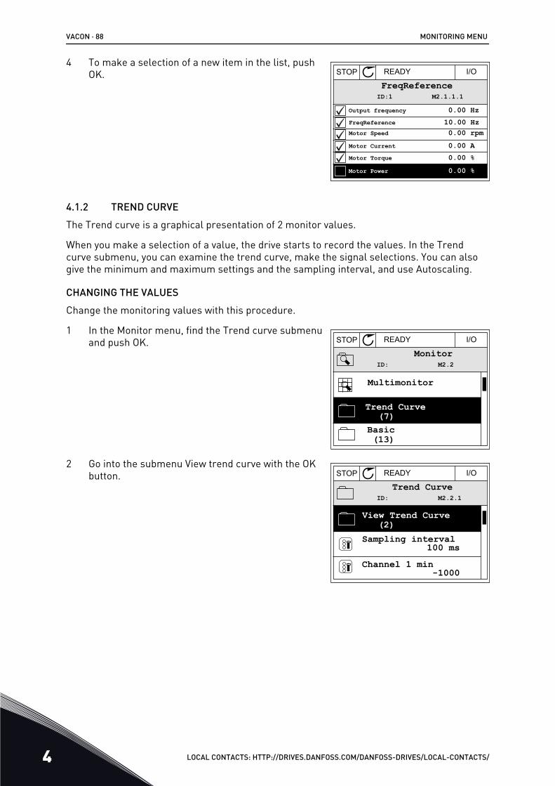
4 To make a selection of a new item in the list, pushOK. STOP READY I/O
ID:1 M2.1.1.1FreqReference
0.00 %Motor Power
Output frequencyFreqReferenceMotor Speed
Motor CurrentMotor Torque
0.00 Hz10.00 Hz0.00 rpm0.00 A0.00 %
4.1.2 TREND CURVEThe Trend curve is a graphical presentation of 2 monitor values.
When you make a selection of a value, the drive starts to record the values. In the Trendcurve submenu, you can examine the trend curve, make the signal selections. You can alsogive the minimum and maximum settings and the sampling interval, and use Autoscaling.
CHANGING THE VALUESChange the monitoring values with this procedure.
1 In the Monitor menu, find the Trend curve submenuand push OK. STOP READY I/O
ID: M2.2Monitor
Multimonitor
Basic
Trend Curve
(13)
(7)
2 Go into the submenu View trend curve with the OKbutton. STOP READY I/O
ID: M2.2.1Trend Curve
Channel 1 min
View Trend Curve
-1000
Sampling interval100 ms
(2)
VACON · 88 MONITORING MENU
4 LOCAL CONTACTS: HTTP://DRIVES.DANFOSS.COM/DANFOSS-DRIVES/LOCAL-CONTACTS/
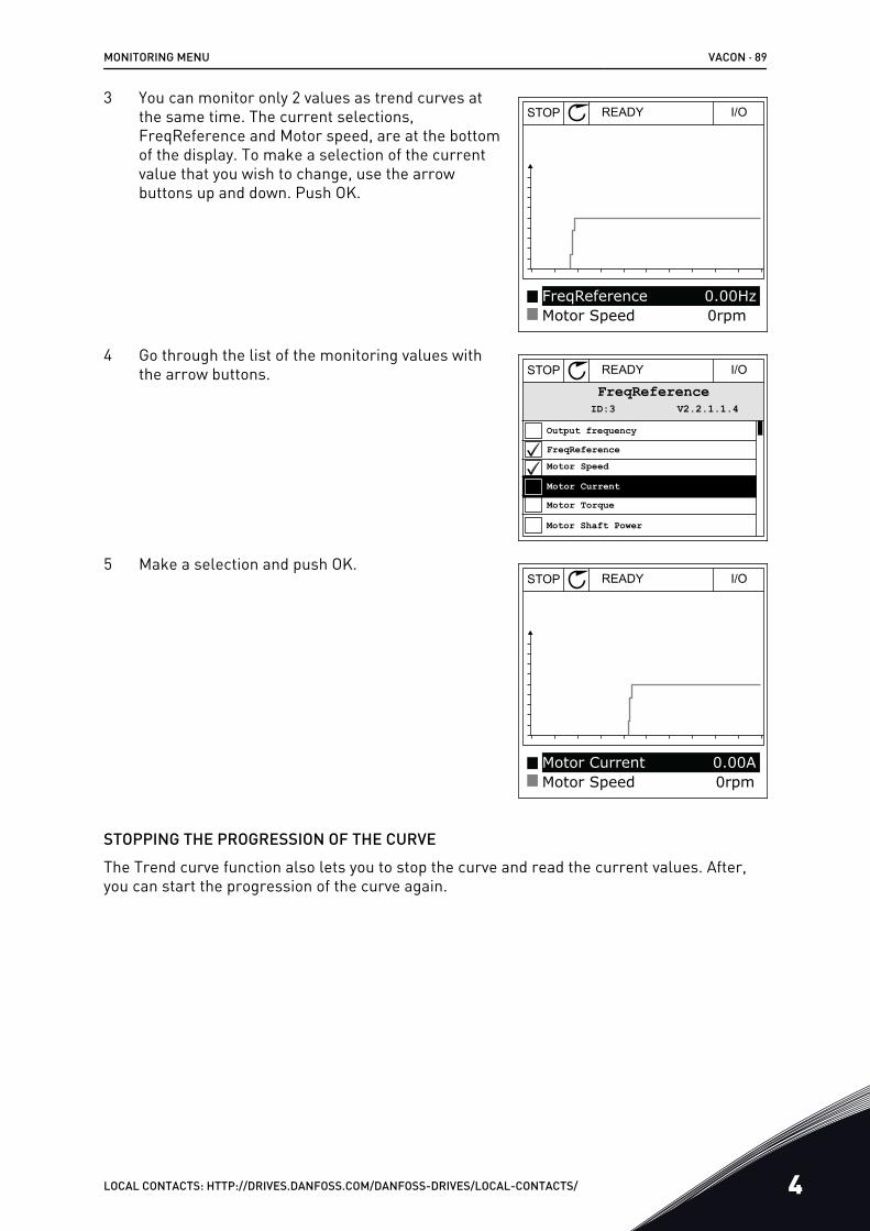
3 You can monitor only 2 values as trend curves atthe same time. The current selections,FreqReference and Motor speed, are at the bottomof the display. To make a selection of the currentvalue that you wish to change, use the arrowbuttons up and down. Push OK.
STOP READY I/O
FreqReferenceMotor Speed
0.00Hz0rpm
4 Go through the list of the monitoring values withthe arrow buttons. STOP READY I/O
ID:3 V2.2.1.1.4FreqReference
Motor Shaft Power
Output frequencyFreqReferenceMotor Speed
Motor CurrentMotor Torque
5 Make a selection and push OK.STOP READY I/O
Motor CurrentMotor Speed
0.00A0rpm
STOPPING THE PROGRESSION OF THE CURVEThe Trend curve function also lets you to stop the curve and read the current values. After,you can start the progression of the curve again.
MONITORING MENU VACON · 89
LOCAL CONTACTS: HTTP://DRIVES.DANFOSS.COM/DANFOSS-DRIVES/LOCAL-CONTACTS/ 4
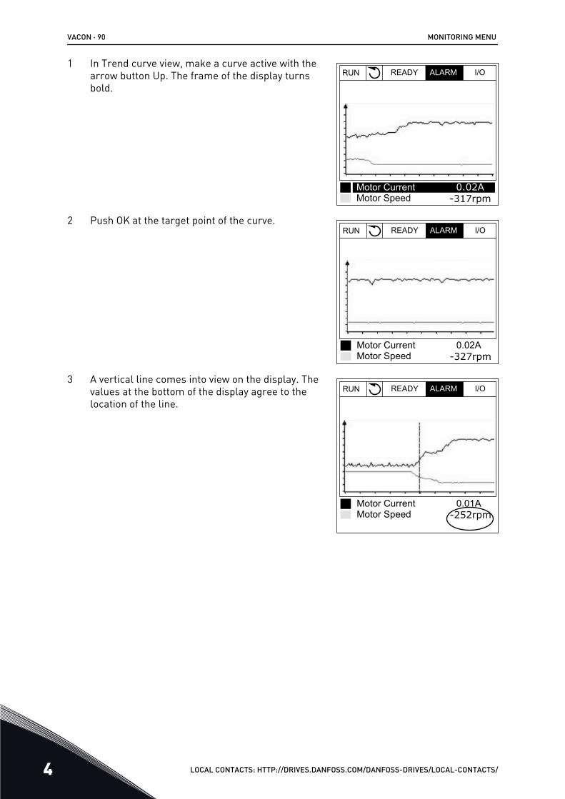
1 In Trend curve view, make a curve active with thearrow button Up. The frame of the display turnsbold.
RUN READY ALARM I/O
Motor CurrentMotor Speed
0.02A-317rpm
2 Push OK at the target point of the curve.RUN READY ALARM I/O
Motor CurrentMotor Speed
0.02A-327rpm
3 A vertical line comes into view on the display. Thevalues at the bottom of the display agree to thelocation of the line.
RUN READY ALARM I/O
Motor CurrentMotor Speed
0.01A-252rpm
VACON · 90 MONITORING MENU
4 LOCAL CONTACTS: HTTP://DRIVES.DANFOSS.COM/DANFOSS-DRIVES/LOCAL-CONTACTS/
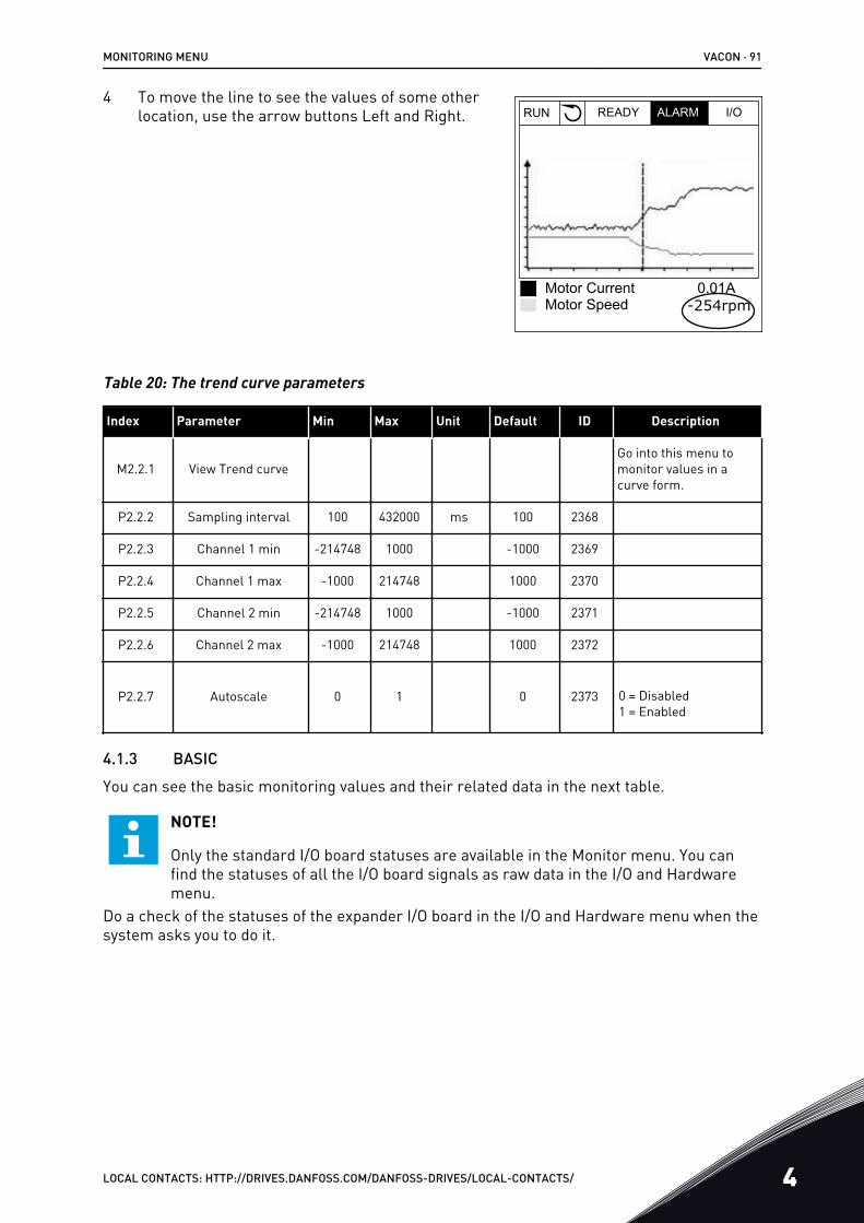
4 To move the line to see the values of some otherlocation, use the arrow buttons Left and Right. RUN READY ALARM I/O
Motor CurrentMotor Speed
0.01A-254rpm
Table 20: The trend curve parameters
Index Parameter Min Max Unit Default ID Description
M2.2.1 View Trend curveGo into this menu tomonitor values in acurve form.
P2.2.2 Sampling interval 100 432000 ms 100 2368
P2.2.3 Channel 1 min -214748 1000 -1000 2369
P2.2.4 Channel 1 max -1000 214748 1000 2370
P2.2.5 Channel 2 min -214748 1000 -1000 2371
P2.2.6 Channel 2 max -1000 214748 1000 2372
P2.2.7 Autoscale 0 1 0 2373 0 = Disabled1 = Enabled
4.1.3 BASICYou can see the basic monitoring values and their related data in the next table.
NOTE!
Only the standard I/O board statuses are available in the Monitor menu. You canfind the statuses of all the I/O board signals as raw data in the I/O and Hardwaremenu.
Do a check of the statuses of the expander I/O board in the I/O and Hardware menu when thesystem asks you to do it.
MONITORING MENU VACON · 91
LOCAL CONTACTS: HTTP://DRIVES.DANFOSS.COM/DANFOSS-DRIVES/LOCAL-CONTACTS/ 4
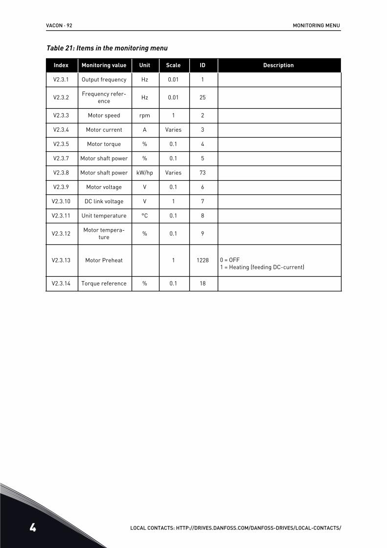
Table 21: Items in the monitoring menu
Index Monitoring value Unit Scale ID Description
V2.3.1 Output frequency Hz 0.01 1
V2.3.2 Frequency refer-ence Hz 0.01 25
V2.3.3 Motor speed rpm 1 2
V2.3.4 Motor current A Varies 3
V2.3.5 Motor torque % 0.1 4
V2.3.7 Motor shaft power % 0.1 5
V2.3.8 Motor shaft power kW/hp Varies 73
V2.3.9 Motor voltage V 0.1 6
V2.3.10 DC link voltage V 1 7
V2.3.11 Unit temperature °C 0.1 8
V2.3.12 Motor tempera-ture % 0.1 9
V2.3.13 Motor Preheat 1 1228 0 = OFF1 = Heating (feeding DC-current)
V2.3.14 Torque reference % 0.1 18
VACON · 92 MONITORING MENU
4 LOCAL CONTACTS: HTTP://DRIVES.DANFOSS.COM/DANFOSS-DRIVES/LOCAL-CONTACTS/
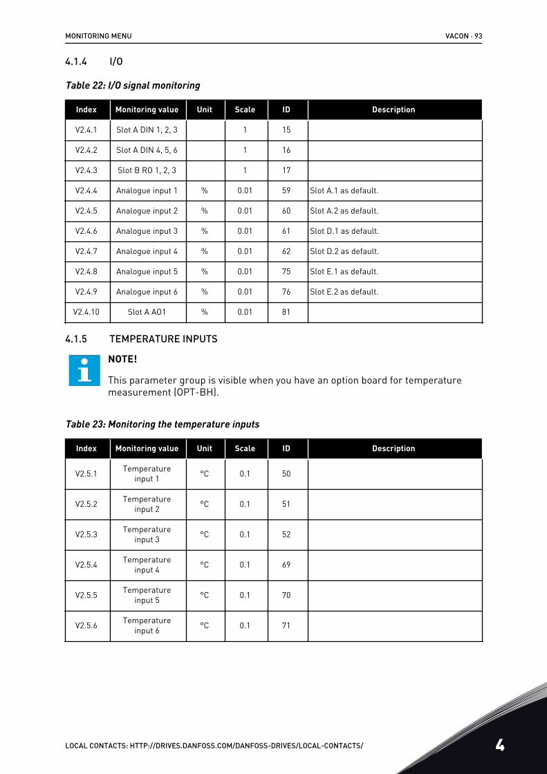
4.1.4 I/O
Table 22: I/O signal monitoring
Index Monitoring value Unit Scale ID Description
V2.4.1 Slot A DIN 1, 2, 3 1 15
V2.4.2 Slot A DIN 4, 5, 6 1 16
V2.4.3 Slot B RO 1, 2, 3 1 17
V2.4.4 Analogue input 1 % 0.01 59 Slot A.1 as default.
V2.4.5 Analogue input 2 % 0.01 60 Slot A.2 as default.
V2.4.6 Analogue input 3 % 0.01 61 Slot D.1 as default.
V2.4.7 Analogue input 4 % 0.01 62 Slot D.2 as default.
V2.4.8 Analogue input 5 % 0.01 75 Slot E.1 as default.
V2.4.9 Analogue input 6 % 0.01 76 Slot E.2 as default.
V2.4.10 Slot A AO1 % 0.01 81
4.1.5 TEMPERATURE INPUTS
NOTE!
This parameter group is visible when you have an option board for temperaturemeasurement (OPT-BH).
Table 23: Monitoring the temperature inputs
Index Monitoring value Unit Scale ID Description
V2.5.1 Temperatureinput 1 °C 0.1 50
V2.5.2 Temperatureinput 2 °C 0.1 51
V2.5.3 Temperatureinput 3 °C 0.1 52
V2.5.4 Temperatureinput 4 °C 0.1 69
V2.5.5 Temperatureinput 5 °C 0.1 70
V2.5.6 Temperatureinput 6 °C 0.1 71
MONITORING MENU VACON · 93
LOCAL CONTACTS: HTTP://DRIVES.DANFOSS.COM/DANFOSS-DRIVES/LOCAL-CONTACTS/ 4
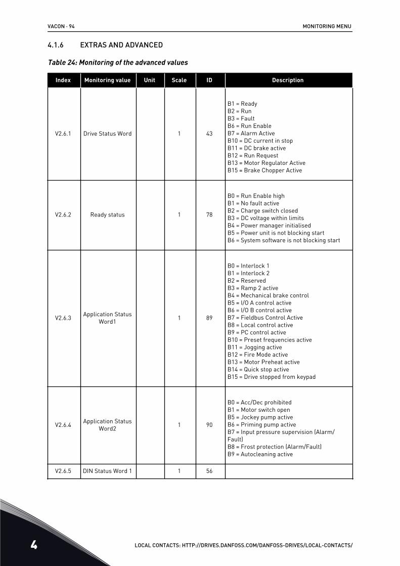
4.1.6 EXTRAS AND ADVANCED
Table 24: Monitoring of the advanced values
Index Monitoring value Unit Scale ID Description
V2.6.1 Drive Status Word 1 43
B1 = ReadyB2 = RunB3 = FaultB6 = Run EnableB7 = Alarm ActiveB10 = DC current in stopB11 = DC brake activeB12 = Run RequestB13 = Motor Regulator ActiveB15 = Brake Chopper Active
V2.6.2 Ready status 1 78
B0 = Run Enable highB1 = No fault activeB2 = Charge switch closedB3 = DC voltage within limitsB4 = Power manager initialisedB5 = Power unit is not blocking startB6 = System software is not blocking start
V2.6.3 Application StatusWord1 1 89
B0 = Interlock 1B1 = Interlock 2B2 = ReservedB3 = Ramp 2 activeB4 = Mechanical brake controlB5 = I/O A control activeB6 = I/O B control activeB7 = Fieldbus Control ActiveB8 = Local control activeB9 = PC control activeB10 = Preset frequencies activeB11 = Jogging activeB12 = Fire Mode activeB13 = Motor Preheat activeB14 = Quick stop activeB15 = Drive stopped from keypad
V2.6.4 Application StatusWord2 1 90
B0 = Acc/Dec prohibitedB1 = Motor switch openB5 = Jockey pump activeB6 = Priming pump activeB7 = Input pressure supervision (Alarm/Fault)B8 = Frost protection (Alarm/Fault)B9 = Autocleaning active
V2.6.5 DIN Status Word 1 1 56
VACON · 94 MONITORING MENU
4 LOCAL CONTACTS: HTTP://DRIVES.DANFOSS.COM/DANFOSS-DRIVES/LOCAL-CONTACTS/
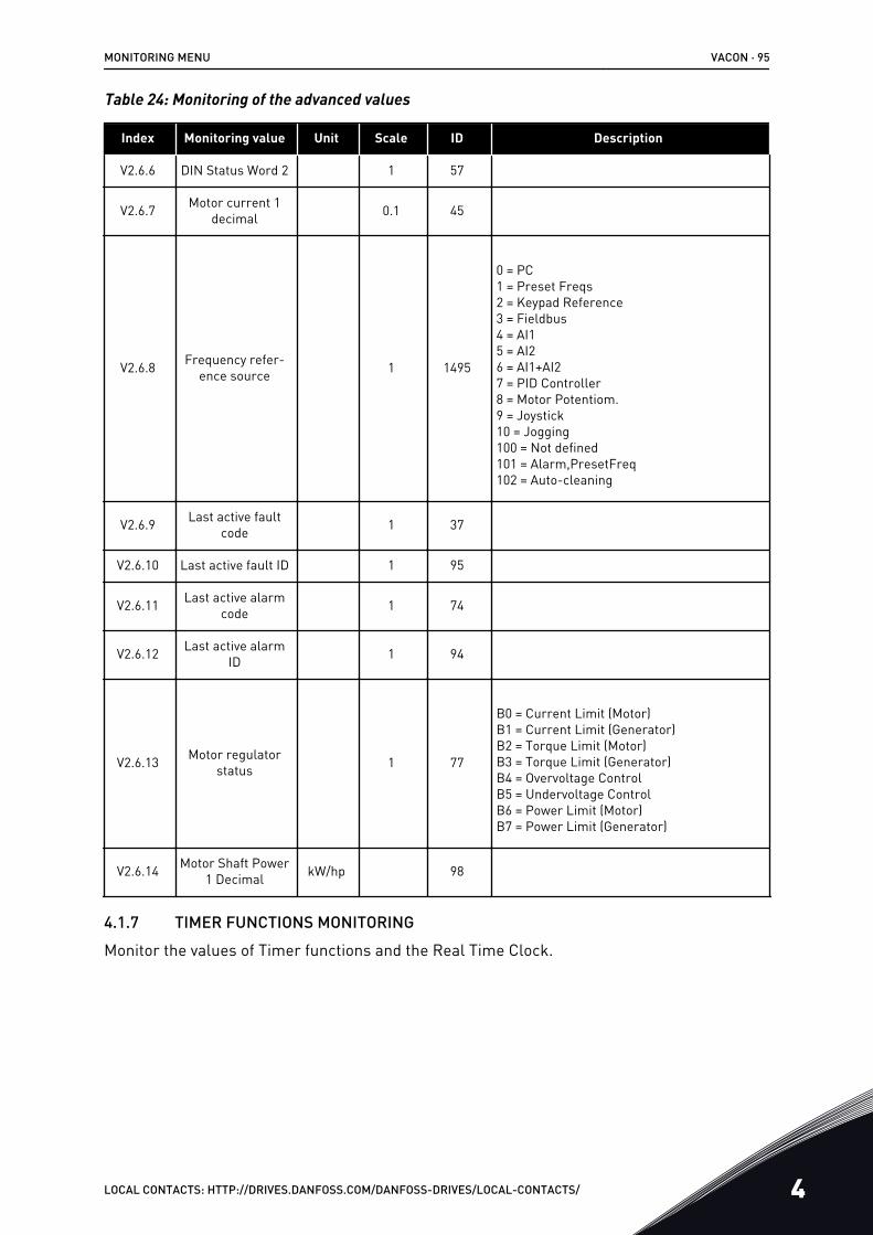
Table 24: Monitoring of the advanced values
Index Monitoring value Unit Scale ID Description
V2.6.6 DIN Status Word 2 1 57
V2.6.7 Motor current 1decimal 0.1 45
V2.6.8 Frequency refer-ence source 1 1495
0 = PC1 = Preset Freqs2 = Keypad Reference3 = Fieldbus4 = AI15 = AI26 = AI1+AI27 = PID Controller8 = Motor Potentiom.9 = Joystick10 = Jogging100 = Not defined101 = Alarm,PresetFreq102 = Auto-cleaning
V2.6.9 Last active faultcode 1 37
V2.6.10 Last active fault ID 1 95
V2.6.11 Last active alarmcode 1 74
V2.6.12 Last active alarmID 1 94
V2.6.13 Motor regulatorstatus 1 77
B0 = Current Limit (Motor)B1 = Current Limit (Generator)B2 = Torque Limit (Motor)B3 = Torque Limit (Generator)B4 = Overvoltage ControlB5 = Undervoltage ControlB6 = Power Limit (Motor)B7 = Power Limit (Generator)
V2.6.14 Motor Shaft Power1 Decimal kW/hp 98
4.1.7 TIMER FUNCTIONS MONITORINGMonitor the values of Timer functions and the Real Time Clock.
MONITORING MENU VACON · 95
LOCAL CONTACTS: HTTP://DRIVES.DANFOSS.COM/DANFOSS-DRIVES/LOCAL-CONTACTS/ 4
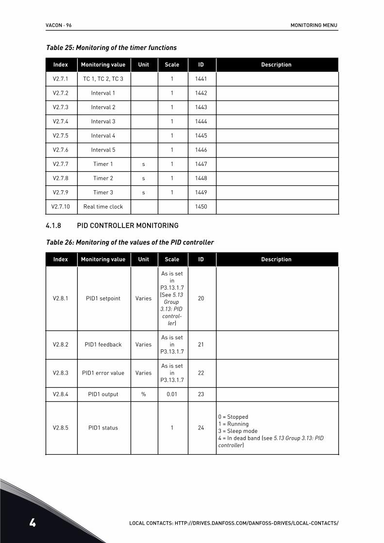
Table 25: Monitoring of the timer functions
Index Monitoring value Unit Scale ID Description
V2.7.1 TC 1, TC 2, TC 3 1 1441
V2.7.2 Interval 1 1 1442
V2.7.3 Interval 2 1 1443
V2.7.4 Interval 3 1 1444
V2.7.5 Interval 4 1 1445
V2.7.6 Interval 5 1 1446
V2.7.7 Timer 1 s 1 1447
V2.7.8 Timer 2 s 1 1448
V2.7.9 Timer 3 s 1 1449
V2.7.10 Real time clock 1450
4.1.8 PID CONTROLLER MONITORING
Table 26: Monitoring of the values of the PID controller
Index Monitoring value Unit Scale ID Description
V2.8.1 PID1 setpoint Varies
As is setin
P3.13.1.7(See 5.13
Group 3.13: PID control-
ler)
20
V2.8.2 PID1 feedback VariesAs is set
inP3.13.1.7
21
V2.8.3 PID1 error value VariesAs is set
inP3.13.1.7
22
V2.8.4 PID1 output % 0.01 23
V2.8.5 PID1 status 1 24
0 = Stopped1 = Running3 = Sleep mode4 = In dead band (see 5.13 Group 3.13: PID controller)
VACON · 96 MONITORING MENU
4 LOCAL CONTACTS: HTTP://DRIVES.DANFOSS.COM/DANFOSS-DRIVES/LOCAL-CONTACTS/

4.1.9 EXTERNAL PID CONTROLLER MONITORING
Table 27: Monitoring of the values of the external PID controller
Index Monitoring value Unit Scale ID Description
V2.9.1 ExtPID Setpoint Varies
As set inP3.14.1.1
0 (See5.14
Group 3.14:
External PID con-troller)
83
V2.9.2 ExtPID Feedback VariesAs set inP3.14.1.1
084
V2.9.3 ExtPID Error VariesAs set inP3.14.1.1
085
V2.9.4 ExtPID Output % 0.01 86
V2.9.5 ExtPID Status 1 87
0=Stopped1=Running2=In dead band (see 5.14 Group 3.14: External PID controller)
4.1.10 MULTI-PUMP MONITORING
Table 28: Multi-pump monitoring
Index Monitoring value Unit Scale ID Description
V2.10.1 Motors running 1 30
V2.10.2 Autochange 1 1114
4.1.11 MAINTENANCE COUNTERS
Table 29: Maintenance counter monitoring
Index Monitoring value Unit Scale ID Description
V2.11.1 Maintenancecounter 1 h/ kRev Varies 1101
MONITORING MENU VACON · 97
LOCAL CONTACTS: HTTP://DRIVES.DANFOSS.COM/DANFOSS-DRIVES/LOCAL-CONTACTS/ 4
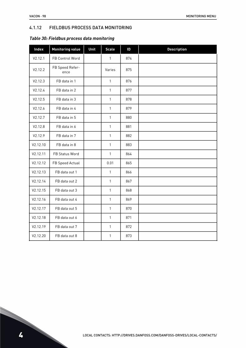
4.1.12 FIELDBUS PROCESS DATA MONITORING
Table 30: Fieldbus process data monitoring
Index Monitoring value Unit Scale ID Description
V2.12.1 FB Control Word 1 874
V2.12.2 FB Speed Refer-ence Varies 875
V2.12.3 FB data in 1 1 876
V2.12.4 FB data in 2 1 877
V2.12.5 FB data in 3 1 878
V2.12.6 FB data in 4 1 879
V2.12.7 FB data in 5 1 880
V2.12.8 FB data in 6 1 881
V2.12.9 FB data in 7 1 882
V2.12.10 FB data in 8 1 883
V2.12.11 FB Status Word 1 864
V2.12.12 FB Speed Actual 0.01 865
V2.12.13 FB data out 1 1 866
V2.12.14 FB data out 2 1 867
V2.12.15 FB data out 3 1 868
V2.12.16 FB data out 4 1 869
V2.12.17 FB data out 5 1 870
V2.12.18 FB data out 6 1 871
V2.12.19 FB data out 7 1 872
V2.12.20 FB data out 8 1 873
VACON · 98 MONITORING MENU
4 LOCAL CONTACTS: HTTP://DRIVES.DANFOSS.COM/DANFOSS-DRIVES/LOCAL-CONTACTS/
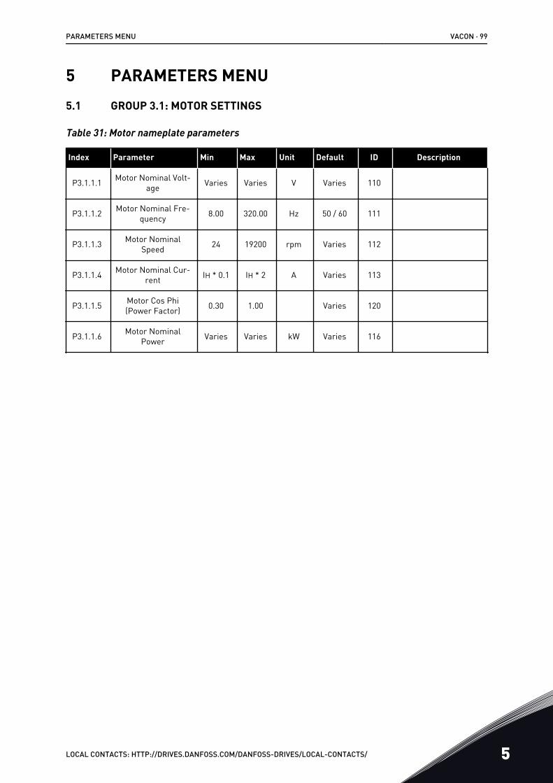
5 PARAMETERS MENU5.1 GROUP 3.1: MOTOR SETTINGS
Table 31: Motor nameplate parameters
Index Parameter Min Max Unit Default ID Description
P3.1.1.1 Motor Nominal Volt-age Varies Varies V Varies 110
P3.1.1.2 Motor Nominal Fre-quency 8.00 320.00 Hz 50 / 60 111
P3.1.1.3 Motor NominalSpeed 24 19200 rpm Varies 112
P3.1.1.4 Motor Nominal Cur-rent IH * 0.1 IH * 2 A Varies 113
P3.1.1.5 Motor Cos Phi(Power Factor) 0.30 1.00 Varies 120
P3.1.1.6 Motor NominalPower Varies Varies kW Varies 116
PARAMETERS MENU VACON · 99
LOCAL CONTACTS: HTTP://DRIVES.DANFOSS.COM/DANFOSS-DRIVES/LOCAL-CONTACTS/ 5
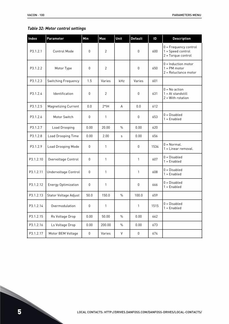
Table 32: Motor control settings
Index Parameter Min Max Unit Default ID Description
P3.1.2.1 Control Mode 0 2 0 6000 = Frequency control1 = Speed control2 = Torque control
P3.1.2.2 Motor Type 0 2 0 6500 = Induction motor1 = PM motor2 = Reluctance motor
P3.1.2.3 Switching Frequency 1.5 Varies kHz Varies 601
P3.1.2.4 Identification 0 2 0 6310 = No action1 = At standstill2 = With rotation
P3.1.2.5 Magnetizing Current 0.0 2*IH A 0.0 612
P3.1.2.6 Motor Switch 0 1 0 653 0 = Disabled1 = Enabled
P3.1.2.7 Load Drooping 0.00 20.00 % 0.00 620
P3.1.2.8 Load Drooping Time 0.00 2.00 s 0.00 656
P3.1.2.9 Load Drooping Mode 0 1 0 1534 0 = Normal.1 = Linear removal.
P3.1.2.10 Overvoltage Control 0 1 1 607 0 = Disabled1 = Enabled
P3.1.2.11 Undervoltage Control 0 1 1 608 0 = Disabled1 = Enabled
P3.1.2.12 Energy Optimization 0 1 0 666 0 = Disabled1 = Enabled
P3.1.2.13 Stator Voltage Adjust 50.0 150.0 % 100.0 659
P3.1.2.14 Overmodulation 0 1 1 1515 0 = Disabled1 = Enabled
P3.1.2.15 Rs Voltage Drop 0.00 50.00 % 0.00 662
P3.1.2.16 Ls Voltage Drop 0.00 200.00 % 0.00 673
P3.1.2.17 Motor BEM Voltage 0 Varies V 0 674
VACON · 100 PARAMETERS MENU
5 LOCAL CONTACTS: HTTP://DRIVES.DANFOSS.COM/DANFOSS-DRIVES/LOCAL-CONTACTS/
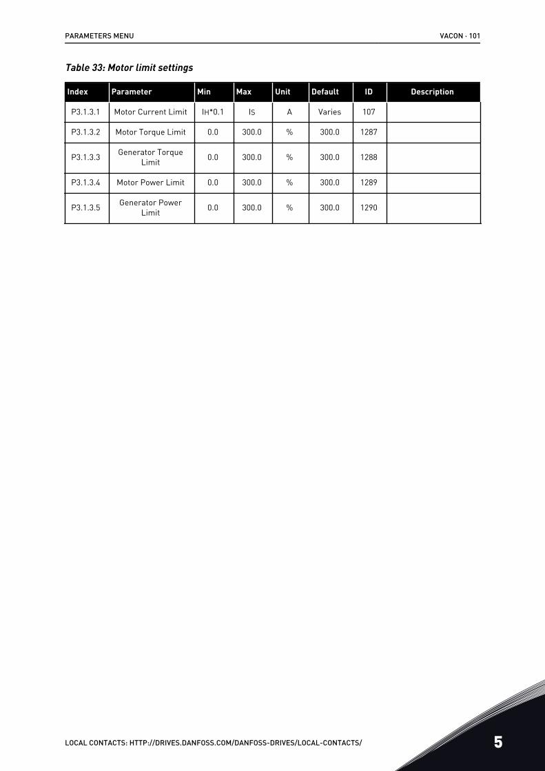
Table 33: Motor limit settings
Index Parameter Min Max Unit Default ID Description
P3.1.3.1 Motor Current Limit IH*0.1 IS A Varies 107
P3.1.3.2 Motor Torque Limit 0.0 300.0 % 300.0 1287
P3.1.3.3 Generator TorqueLimit 0.0 300.0 % 300.0 1288
P3.1.3.4 Motor Power Limit 0.0 300.0 % 300.0 1289
P3.1.3.5 Generator PowerLimit 0.0 300.0 % 300.0 1290
PARAMETERS MENU VACON · 101
LOCAL CONTACTS: HTTP://DRIVES.DANFOSS.COM/DANFOSS-DRIVES/LOCAL-CONTACTS/ 5
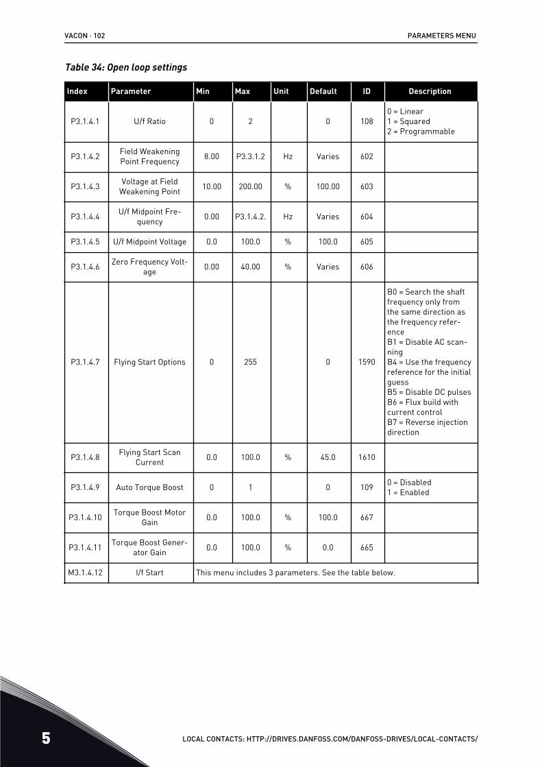
Table 34: Open loop settings
Index Parameter Min Max Unit Default ID Description
P3.1.4.1 U/f Ratio 0 2 0 1080 = Linear1 = Squared2 = Programmable
P3.1.4.2 Field WeakeningPoint Frequency 8.00 P3.3.1.2 Hz Varies 602
P3.1.4.3 Voltage at FieldWeakening Point 10.00 200.00 % 100.00 603
P3.1.4.4 U/f Midpoint Fre-quency 0.00 P3.1.4.2. Hz Varies 604
P3.1.4.5 U/f Midpoint Voltage 0.0 100.0 % 100.0 605
P3.1.4.6 Zero Frequency Volt-age 0.00 40.00 % Varies 606
P3.1.4.7 Flying Start Options 0 255 0 1590
B0 = Search the shaftfrequency only fromthe same direction asthe frequency refer-enceB1 = Disable AC scan-ningB4 = Use the frequencyreference for the initialguessB5 = Disable DC pulsesB6 = Flux build withcurrent controlB7 = Reverse injectiondirection
P3.1.4.8 Flying Start ScanCurrent 0.0 100.0 % 45.0 1610
P3.1.4.9 Auto Torque Boost 0 1 0 109 0 = Disabled1 = Enabled
P3.1.4.10 Torque Boost MotorGain 0.0 100.0 % 100.0 667
P3.1.4.11 Torque Boost Gener-ator Gain 0.0 100.0 % 0.0 665
M3.1.4.12 I/f Start This menu includes 3 parameters. See the table below.
VACON · 102 PARAMETERS MENU
5 LOCAL CONTACTS: HTTP://DRIVES.DANFOSS.COM/DANFOSS-DRIVES/LOCAL-CONTACTS/
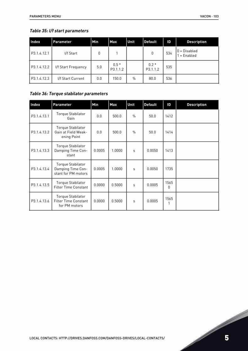
Table 35: I/f start parameters
Index Parameter Min Max Unit Default ID Description
P3.1.4.12.1 I/f Start 0 1 0 534 0 = Disabled1 = Enabled
P3.1.4.12.2 I/f Start Frequency 5.0 0.5 *P3.1.1.2
0.2 *P3.1.1.2 535
P3.1.4.12.3 I/f Start Current 0.0 150.0 % 80.0 536
Table 36: Torque stabilator parameters
Index Parameter Min Max Unit Default ID Description
P3.1.4.13.1 Torque StabilatorGain 0.0 500.0 % 50.0 1412
P3.1.4.13.2Torque Stabilator
Gain at Field Weak-ening Point
0.0 500.0 % 50.0 1414
P3.1.4.13.3Torque Stabilator
Damping Time Con-stant
0.0005 1.0000 s 0.0050 1413
P3.1.4.13.4Torque Stabilator
Damping Time Con-stant for PM motors
0.0005 1.0000 s 0.0050 1735
P3.1.4.13.5 Torque StabilatorFilter Time Constant 0.0000 0.5000 s 0.0005 1565
0
P3.1.4.13.6Torque Stabilator
Filter Time Constantfor PM motors
0.0000 0.5000 s 0.0005 15651
PARAMETERS MENU VACON · 103
LOCAL CONTACTS: HTTP://DRIVES.DANFOSS.COM/DANFOSS-DRIVES/LOCAL-CONTACTS/ 5
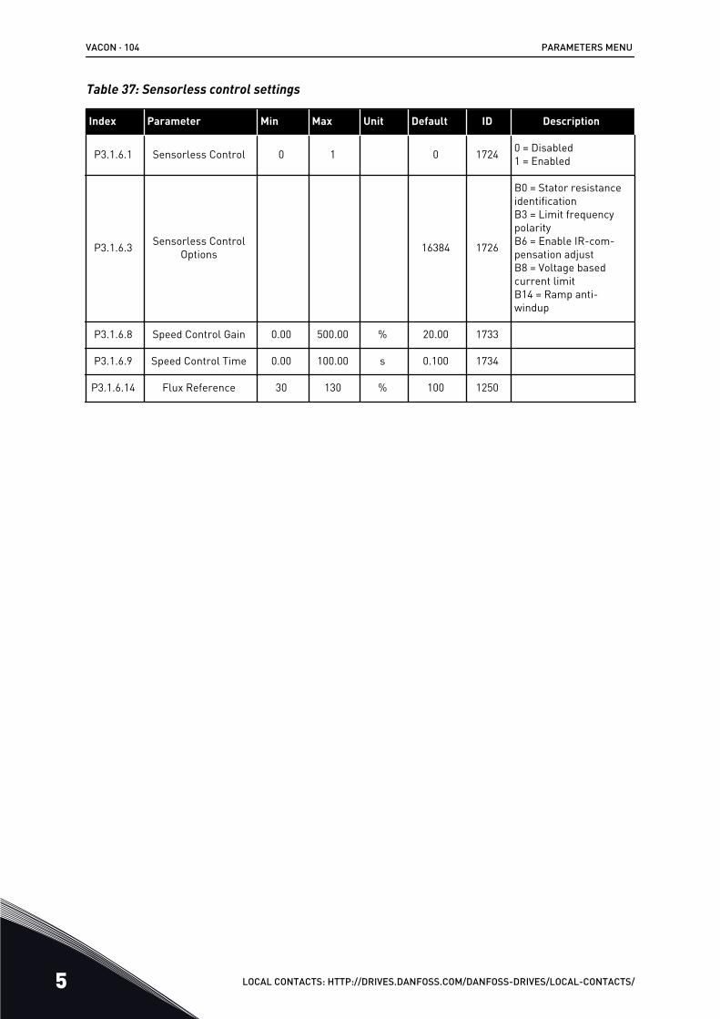
Table 37: Sensorless control settings
Index Parameter Min Max Unit Default ID Description
P3.1.6.1 Sensorless Control 0 1 0 1724 0 = Disabled1 = Enabled
P3.1.6.3 Sensorless ControlOptions 16384 1726
B0 = Stator resistanceidentificationB3 = Limit frequencypolarityB6 = Enable IR-com-pensation adjustB8 = Voltage basedcurrent limitB14 = Ramp anti-windup
P3.1.6.8 Speed Control Gain 0.00 500.00 % 20.00 1733
P3.1.6.9 Speed Control Time 0.00 100.00 s 0.100 1734
P3.1.6.14 Flux Reference 30 130 % 100 1250
VACON · 104 PARAMETERS MENU
5 LOCAL CONTACTS: HTTP://DRIVES.DANFOSS.COM/DANFOSS-DRIVES/LOCAL-CONTACTS/
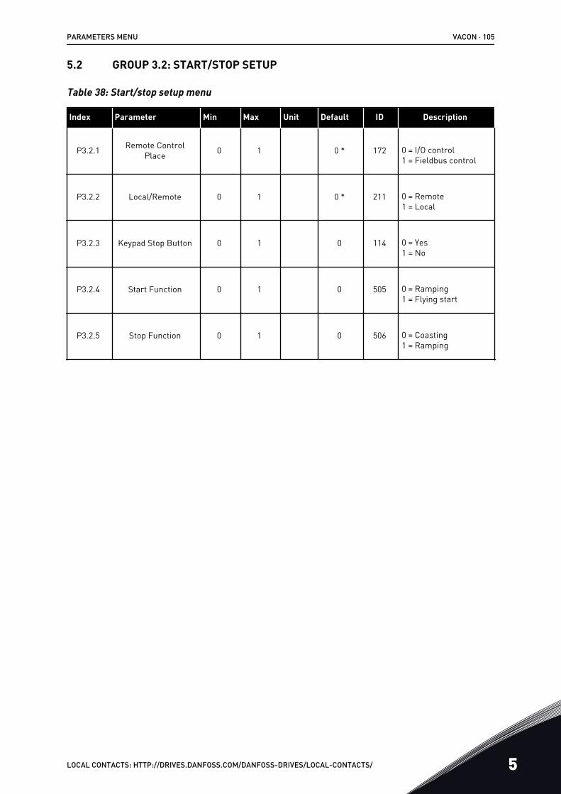
5.2 GROUP 3.2: START/STOP SETUP
Table 38: Start/stop setup menu
Index Parameter Min Max Unit Default ID Description
P3.2.1 Remote ControlPlace 0 1 0 * 172 0 = I/O control
1 = Fieldbus control
P3.2.2 Local/Remote 0 1 0 * 211 0 = Remote1 = Local
P3.2.3 Keypad Stop Button 0 1 0 114 0 = Yes1 = No
P3.2.4 Start Function 0 1 0 505 0 = Ramping1 = Flying start
P3.2.5 Stop Function 0 1 0 506 0 = Coasting1 = Ramping
PARAMETERS MENU VACON · 105
LOCAL CONTACTS: HTTP://DRIVES.DANFOSS.COM/DANFOSS-DRIVES/LOCAL-CONTACTS/ 5
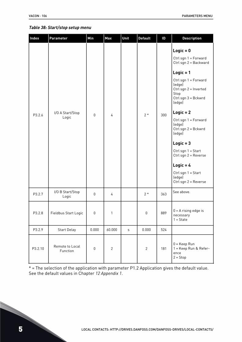
Table 38: Start/stop setup menu
Index Parameter Min Max Unit Default ID Description
P3.2.6 I/O A Start/StopLogic 0 4 2 * 300
Logic = 0Ctrl sgn 1 = ForwardCtrl sgn 2 = Backward
Logic = 1Ctrl sgn 1 = Forward(edge)Ctrl sgn 2 = InvertedStopCtrl sgn 3 = Bckwrd(edge)
Logic = 2Ctrl sgn 1 = Forward(edge)Ctrl sgn 2 = Bckwrd(edge)
Logic = 3Ctrl sgn 1 = StartCtrl sgn 2 = Reverse
Logic = 4Ctrl sgn 1 = Start(edge)Ctrl sgn 2 = Reverse
P3.2.7 I/O B Start/StopLogic 0 4 2 * 363 See above.
P3.2.8 Fieldbus Start Logic 0 1 0 889 0 = A rising edge isnecessary1 = State
P3.2.9 Start Delay 0.000 60.000 s 0.000 524
P3.2.10 Remote to LocalFunction 0 2 2 181
0 = Keep Run1 = Keep Run & Refer-ence2 = Stop
* = The selection of the application with parameter P1.2 Application gives the default value.See the default values in Chapter 12 Appendix 1.
VACON · 106 PARAMETERS MENU
5 LOCAL CONTACTS: HTTP://DRIVES.DANFOSS.COM/DANFOSS-DRIVES/LOCAL-CONTACTS/
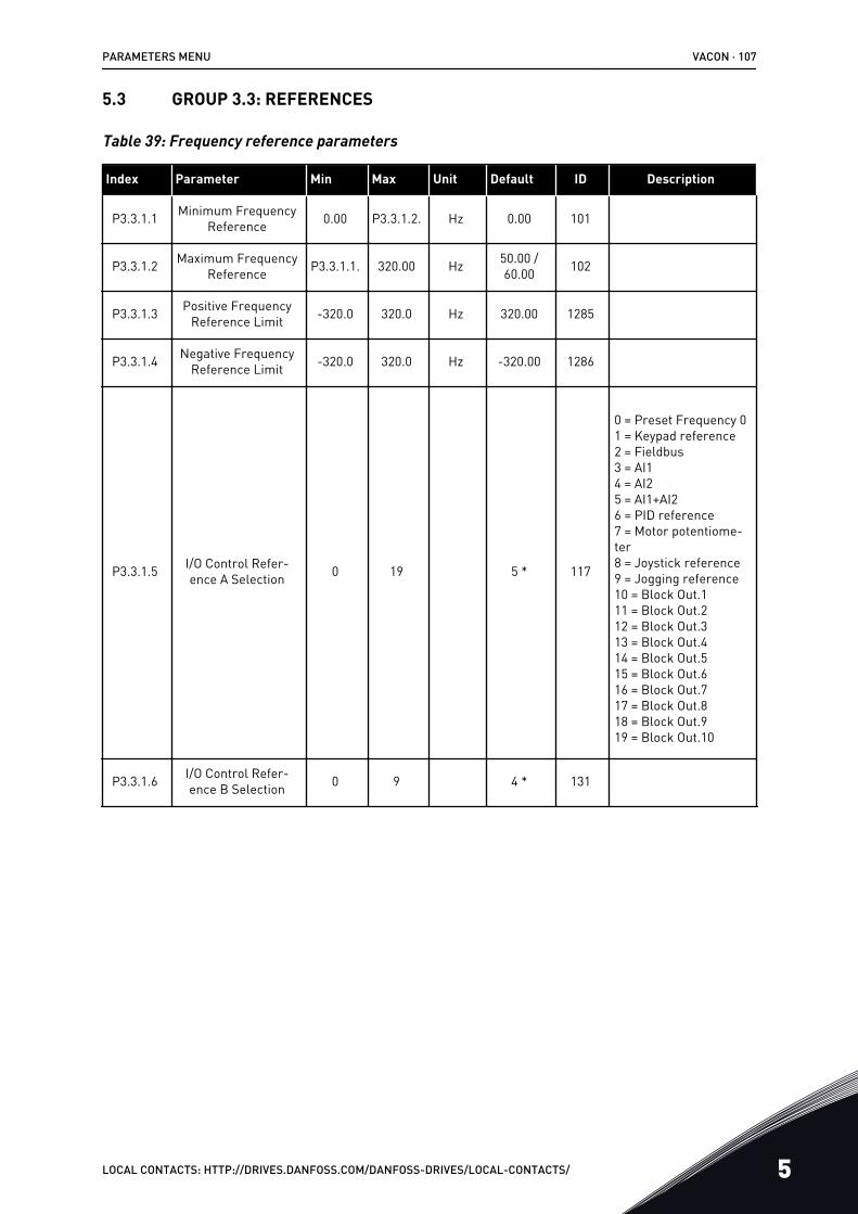
5.3 GROUP 3.3: REFERENCES
Table 39: Frequency reference parameters
Index Parameter Min Max Unit Default ID Description
P3.3.1.1 Minimum FrequencyReference 0.00 P3.3.1.2. Hz 0.00 101
P3.3.1.2 Maximum FrequencyReference P3.3.1.1. 320.00 Hz 50.00 /
60.00 102
P3.3.1.3 Positive FrequencyReference Limit -320.0 320.0 Hz 320.00 1285
P3.3.1.4 Negative FrequencyReference Limit -320.0 320.0 Hz -320.00 1286
P3.3.1.5 I/O Control Refer-ence A Selection 0 19 5 * 117
0 = Preset Frequency 01 = Keypad reference2 = Fieldbus3 = AI14 = AI25 = AI1+AI26 = PID reference7 = Motor potentiome-ter8 = Joystick reference9 = Jogging reference10 = Block Out.111 = Block Out.212 = Block Out.313 = Block Out.414 = Block Out.515 = Block Out.616 = Block Out.717 = Block Out.818 = Block Out.919 = Block Out.10
P3.3.1.6 I/O Control Refer-ence B Selection 0 9 4 * 131
PARAMETERS MENU VACON · 107
LOCAL CONTACTS: HTTP://DRIVES.DANFOSS.COM/DANFOSS-DRIVES/LOCAL-CONTACTS/ 5
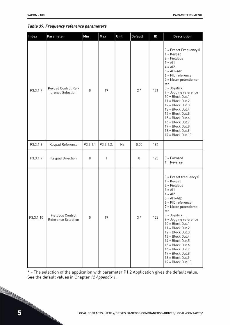
Table 39: Frequency reference parameters
Index Parameter Min Max Unit Default ID Description
P3.3.1.7 Keypad Control Ref-erence Selection 0 19 2 * 121
0 = Preset Frequency 01 = Keypad2 = Fieldbus3 = AI14 = AI25 = AI1+AI26 = PID reference7 = Motor potentiome-ter8 = Joystick9 = Jogging reference10 = Block Out.111 = Block Out.212 = Block Out.313 = Block Out.414 = Block Out.515 = Block Out.616 = Block Out.717 = Block Out.818 = Block Out.919 = Block Out.10
P3.3.1.8 Keypad Reference P3.3.1.1 P3.3.1.2. Hz 0.00 184
P3.3.1.9 Keypad Direction 0 1 0 123 0 = Forward1 = Reverse
P3.3.1.10 Fieldbus ControlReference Selection 0 19 3 * 122
0 = Preset frequency 01 = Keypad2 = Fieldbus3 = AI14 = AI25 = AI1+AI26 = PID reference7 = Motor potentiome-ter8 = Joystick9 = Jogging reference10 = Block Out.111 = Block Out.212 = Block Out.313 = Block Out.414 = Block Out.515 = Block Out.616 = Block Out.717 = Block Out.818 = Block Out.919 = Block Out.10
* = The selection of the application with parameter P1.2 Application gives the default value.See the default values in Chapter 12 Appendix 1.
VACON · 108 PARAMETERS MENU
5 LOCAL CONTACTS: HTTP://DRIVES.DANFOSS.COM/DANFOSS-DRIVES/LOCAL-CONTACTS/
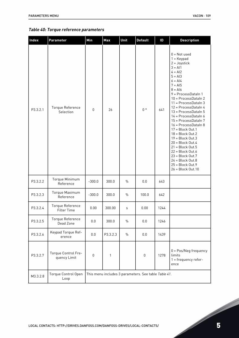
Table 40: Torque reference parameters
Index Parameter Min Max Unit Default ID Description
P3.3.2.1 Torque ReferenceSelection 0 26 0 * 641
0 = Not used1 = Keypad2 = Joystick3 = AI14 = AI25 = AI36 = AI47 = AI58 = AI69 = ProcessDataIn 110 = ProcessDataIn 211 = ProcessDataIn 312 = ProcessDataIn 413 = ProcessDataIn 514 = ProcessDataIn 615 = ProcessDataIn 716 = ProcessDataIn 817 = Block Out.118 = Block Out.219 = Block Out.320 = Block Out.421 = Block Out.522 = Block Out.623 = Block Out.724 = Block Out.825 = Block Out.926 = Block Out.10
P3.3.2.2 Torque MinimumReference -300.0 300.0 % 0.0 643
P3.3.2.3 Torque MaximumReference -300.0 300.0 % 100.0 642
P3.3.2.4 Torque ReferenceFilter Time 0.00 300.00 s 0.00 1244
P3.3.2.5 Torque ReferenceDead Zone 0.0 300.0 % 0.0 1246
P3.3.2.6 Keypad Torque Ref-erence 0.0 P3.3.2.3 % 0.0 1439
P3.3.2.7 Torque Control Fre-quency Limit 0 1 0 1278
0 = Pos/Neg frequencylimits1 = frequency refer-ence
M3.3.2.8 Torque Control OpenLoop
This menu includes 3 parameters. See table Table 41.
PARAMETERS MENU VACON · 109
LOCAL CONTACTS: HTTP://DRIVES.DANFOSS.COM/DANFOSS-DRIVES/LOCAL-CONTACTS/ 5
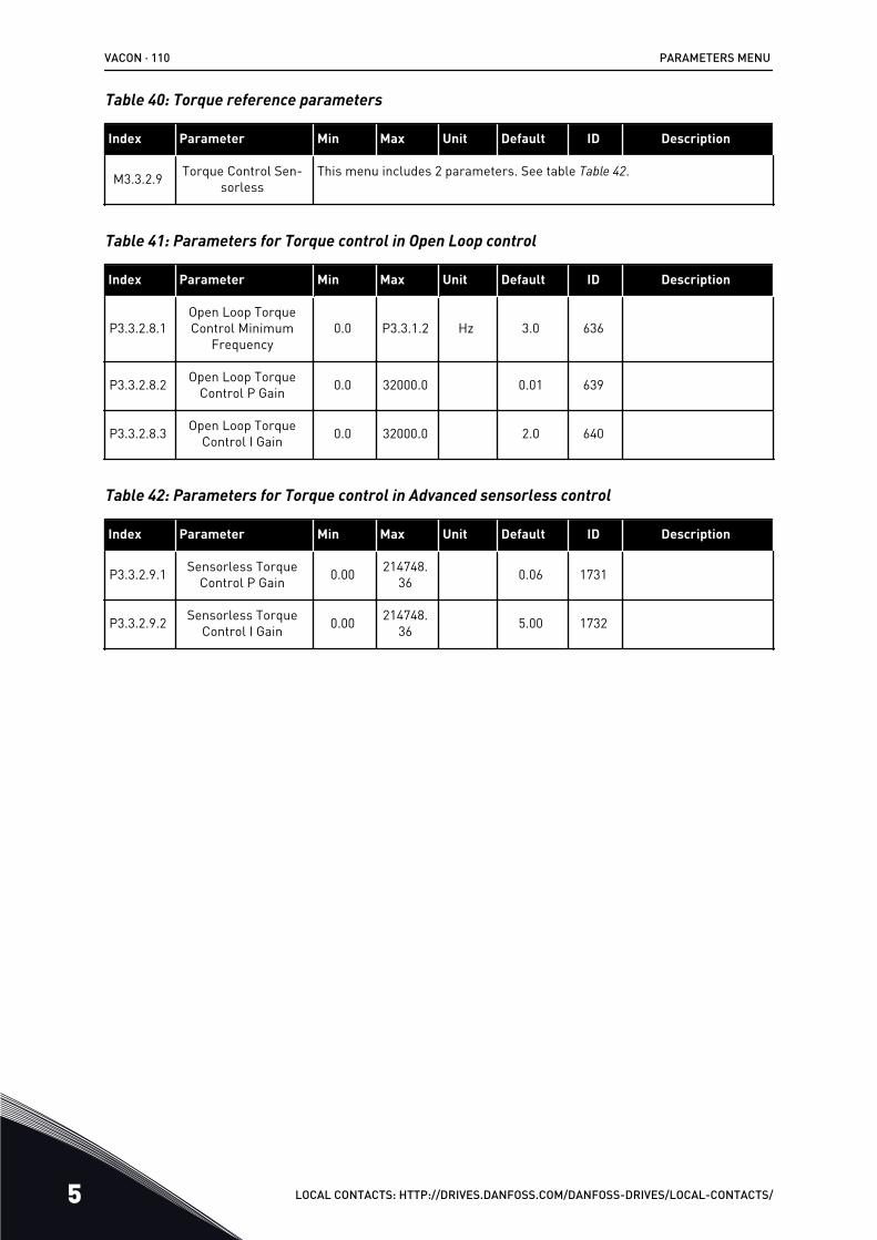
Table 40: Torque reference parameters
Index Parameter Min Max Unit Default ID Description
M3.3.2.9 Torque Control Sen-sorless
This menu includes 2 parameters. See table Table 42.
Table 41: Parameters for Torque control in Open Loop control
Index Parameter Min Max Unit Default ID Description
P3.3.2.8.1Open Loop TorqueControl Minimum
Frequency0.0 P3.3.1.2 Hz 3.0 636
P3.3.2.8.2 Open Loop TorqueControl P Gain 0.0 32000.0 0.01 639
P3.3.2.8.3 Open Loop TorqueControl I Gain 0.0 32000.0 2.0 640
Table 42: Parameters for Torque control in Advanced sensorless control
Index Parameter Min Max Unit Default ID Description
P3.3.2.9.1 Sensorless TorqueControl P Gain 0.00 214748.
36 0.06 1731
P3.3.2.9.2 Sensorless TorqueControl I Gain 0.00 214748.
36 5.00 1732
VACON · 110 PARAMETERS MENU
5 LOCAL CONTACTS: HTTP://DRIVES.DANFOSS.COM/DANFOSS-DRIVES/LOCAL-CONTACTS/
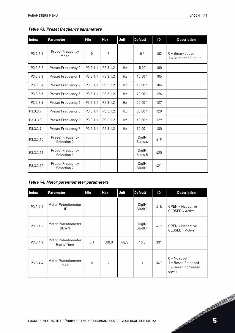
Table 43: Preset frequency parameters
Index Parameter Min Max Unit Default ID Description
P3.3.3.1 Preset FrequencyMode 0 1 0 * 182 0 = Binary coded
1 = Number of inputs
P3.3.3.2 Preset Frequency 0 P3.3.1.1 P3.3.1.2 Hz 5.00 180
P3.3.3.3 Preset Frequency 1 P3.3.1.1 P3.3.1.2 Hz 10.00 * 105
P3.3.3.4 Preset Frequency 2 P3.3.1.1 P3.3.1.2 Hz 15.00 * 106
P3.3.3.5 Preset Frequency 3 P3.3.1.1 P3.3.1.2 Hz 20.00 * 126
P3.3.3.6 Preset Frequency 4 P3.3.1.1 P3.3.1.2 Hz 25.00 * 127
P3.3.3.7 Preset Frequency 5 P3.3.1.1 P3.3.1.2 Hz 30.00 * 128
P3.3.3.8 Preset Frequency 6 P3.3.1.1 P3.3.1.2 Hz 40.00 * 129
P3.3.3.9 Preset Frequency 7 P3.3.1.1 P3.3.1.2 Hz 50.00 * 130
P3.3.3.10 Preset FrequencySelection 0
DigINSlotA.4 419
P3.3.3.11 Preset FrequencySelection 1
DigINSlotA.5 420
P3.3.3.12 Preset FrequencySelection 2
DigINSlot0.1 421
Table 44: Motor potentiometer parameters
Index Parameter Min Max Unit Default ID Description
P3.3.4.1 Motor PotentiometerUP
DigINSlot0.1 418 OPEN = Not active
CLOSED = Active
P3.3.4.2 Motor PotentiometerDOWN
DigINSlot0.1 417 OPEN = Not active
CLOSED = Active
P3.3.4.3 Motor PotentiometerRamp Time 0.1 500.0 Hz/s 10.0 331
P3.3.4.4 Motor PotentiometerReset 0 2 1 367
0 = No reset1 = Reset if stopped2 = Reset if powereddown
PARAMETERS MENU VACON · 111
LOCAL CONTACTS: HTTP://DRIVES.DANFOSS.COM/DANFOSS-DRIVES/LOCAL-CONTACTS/ 5
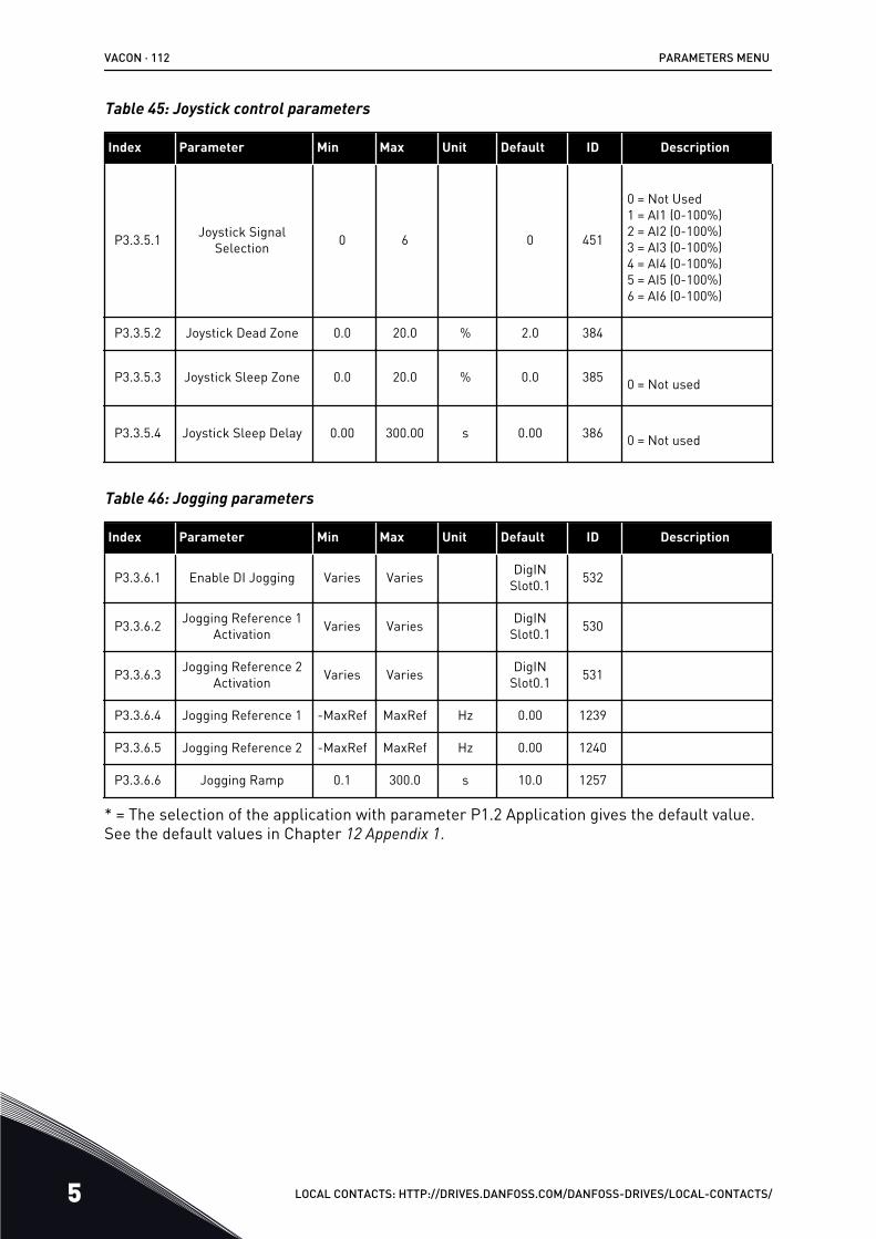
Table 45: Joystick control parameters
Index Parameter Min Max Unit Default ID Description
P3.3.5.1 Joystick SignalSelection 0 6 0 451
0 = Not Used1 = AI1 (0-100%)2 = AI2 (0-100%)3 = AI3 (0-100%)4 = AI4 (0-100%)5 = AI5 (0-100%)6 = AI6 (0-100%)
P3.3.5.2 Joystick Dead Zone 0.0 20.0 % 2.0 384
P3.3.5.3 Joystick Sleep Zone 0.0 20.0 % 0.0 385 0 = Not used
P3.3.5.4 Joystick Sleep Delay 0.00 300.00 s 0.00 386 0 = Not used
Table 46: Jogging parameters
Index Parameter Min Max Unit Default ID Description
P3.3.6.1 Enable DI Jogging Varies Varies DigINSlot0.1 532
P3.3.6.2 Jogging Reference 1Activation Varies Varies DigIN
Slot0.1 530
P3.3.6.3 Jogging Reference 2Activation Varies Varies DigIN
Slot0.1 531
P3.3.6.4 Jogging Reference 1 -MaxRef MaxRef Hz 0.00 1239
P3.3.6.5 Jogging Reference 2 -MaxRef MaxRef Hz 0.00 1240
P3.3.6.6 Jogging Ramp 0.1 300.0 s 10.0 1257
* = The selection of the application with parameter P1.2 Application gives the default value.See the default values in Chapter 12 Appendix 1.
VACON · 112 PARAMETERS MENU
5 LOCAL CONTACTS: HTTP://DRIVES.DANFOSS.COM/DANFOSS-DRIVES/LOCAL-CONTACTS/
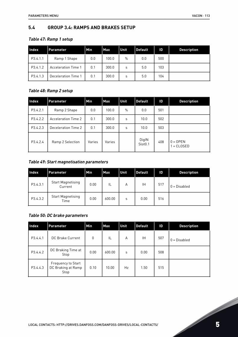
5.4 GROUP 3.4: RAMPS AND BRAKES SETUP
Table 47: Ramp 1 setup
Index Parameter Min Max Unit Default ID Description
P3.4.1.1 Ramp 1 Shape 0.0 100.0 % 0.0 500
P3.4.1.2 Acceleration Time 1 0.1 300.0 s 5.0 103
P3.4.1.3 Deceleration Time 1 0.1 300.0 s 5.0 104
Table 48: Ramp 2 setup
Index Parameter Min Max Unit Default ID Description
P3.4.2.1 Ramp 2 Shape 0.0 100.0 % 0.0 501
P3.4.2.2 Acceleration Time 2 0.1 300.0 s 10.0 502
P3.4.2.3 Deceleration Time 2 0.1 300.0 s 10.0 503
P3.4.2.4 Ramp 2 Selection Varies Varies DigINSlot0.1 408 0 = OPEN
1 = CLOSED
Table 49: Start magnetisation parameters
Index Parameter Min Max Unit Default ID Description
P3.4.3.1 Start MagnetisingCurrent 0.00 IL A IH 517 0 = Disabled
P3.4.3.2 Start MagnetisingTime 0.00 600.00 s 0.00 516
Table 50: DC brake parameters
Index Parameter Min Max Unit Default ID Description
P3.4.4.1 DC Brake Current 0 IL A IH 507 0 = Disabled
P3.4.4.2 DC Braking Time atStop 0.00 600.00 s 0.00 508
P3.4.4.3Frequency to Start
DC Braking at RampStop
0.10 10.00 Hz 1.50 515
PARAMETERS MENU VACON · 113
LOCAL CONTACTS: HTTP://DRIVES.DANFOSS.COM/DANFOSS-DRIVES/LOCAL-CONTACTS/ 5

Table 51: Flux braking parameters
Index Parameter Min Max Unit Default ID Description
P3.4.5.1 Flux Braking 0 1 0 520 0 = Disabled1 = Enabled
P3.4.5.2 Flux Braking Current 0 IL A IH 519
VACON · 114 PARAMETERS MENU
5 LOCAL CONTACTS: HTTP://DRIVES.DANFOSS.COM/DANFOSS-DRIVES/LOCAL-CONTACTS/
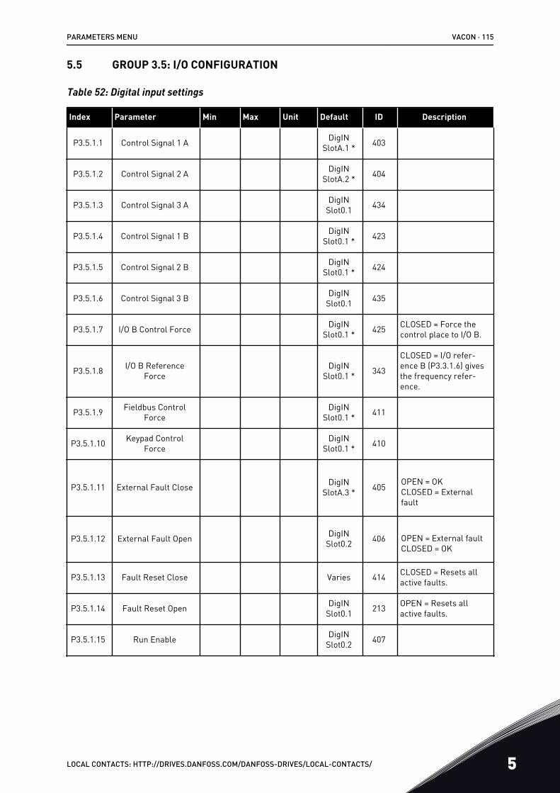
5.5 GROUP 3.5: I/O CONFIGURATION
Table 52: Digital input settings
Index Parameter Min Max Unit Default ID Description
P3.5.1.1 Control Signal 1 A DigINSlotA.1 * 403
P3.5.1.2 Control Signal 2 A DigINSlotA.2 * 404
P3.5.1.3 Control Signal 3 A DigINSlot0.1 434
P3.5.1.4 Control Signal 1 B DigINSlot0.1 * 423
P3.5.1.5 Control Signal 2 B DigINSlot0.1 * 424
P3.5.1.6 Control Signal 3 B DigINSlot0.1 435
P3.5.1.7 I/O B Control Force DigINSlot0.1 * 425 CLOSED = Force the
control place to I/O B.
P3.5.1.8 I/O B ReferenceForce
DigINSlot0.1 * 343
CLOSED = I/O refer-ence B (P3.3.1.6) givesthe frequency refer-ence.
P3.5.1.9 Fieldbus ControlForce
DigINSlot0.1 * 411
P3.5.1.10 Keypad ControlForce
DigINSlot0.1 * 410
P3.5.1.11 External Fault Close DigINSlotA.3 * 405 OPEN = OK
CLOSED = Externalfault
P3.5.1.12 External Fault Open DigINSlot0.2 406 OPEN = External fault
CLOSED = OK
P3.5.1.13 Fault Reset Close Varies 414 CLOSED = Resets allactive faults.
P3.5.1.14 Fault Reset Open DigINSlot0.1 213 OPEN = Resets all
active faults.
P3.5.1.15 Run Enable DigINSlot0.2 407
PARAMETERS MENU VACON · 115
LOCAL CONTACTS: HTTP://DRIVES.DANFOSS.COM/DANFOSS-DRIVES/LOCAL-CONTACTS/ 5
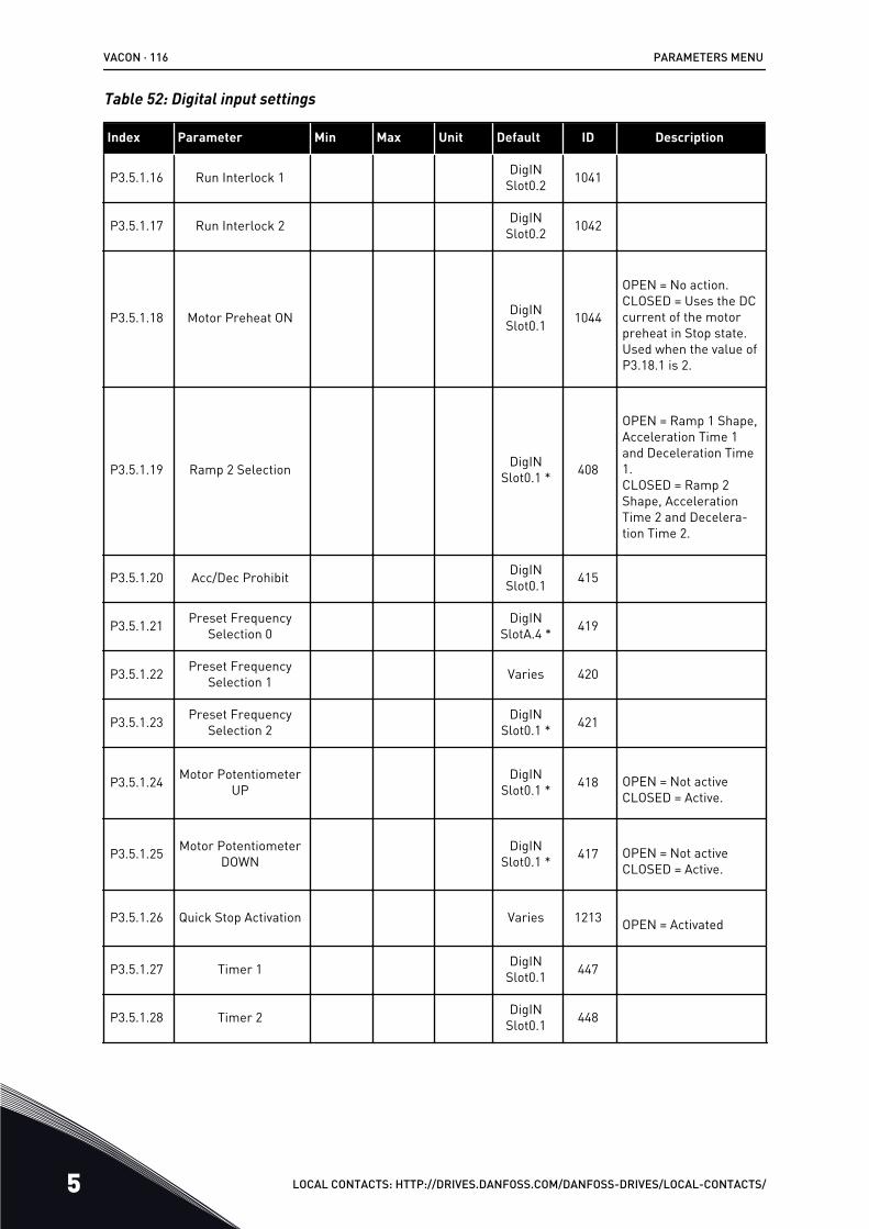
Table 52: Digital input settings
Index Parameter Min Max Unit Default ID Description
P3.5.1.16 Run Interlock 1 DigINSlot0.2 1041
P3.5.1.17 Run Interlock 2 DigINSlot0.2 1042
P3.5.1.18 Motor Preheat ON DigINSlot0.1 1044
OPEN = No action.CLOSED = Uses the DCcurrent of the motorpreheat in Stop state.Used when the value ofP3.18.1 is 2.
P3.5.1.19 Ramp 2 Selection DigINSlot0.1 * 408
OPEN = Ramp 1 Shape,Acceleration Time 1and Deceleration Time1.CLOSED = Ramp 2Shape, AccelerationTime 2 and Decelera-tion Time 2.
P3.5.1.20 Acc/Dec Prohibit DigINSlot0.1 415
P3.5.1.21 Preset FrequencySelection 0
DigINSlotA.4 * 419
P3.5.1.22 Preset FrequencySelection 1 Varies 420
P3.5.1.23 Preset FrequencySelection 2
DigINSlot0.1 * 421
P3.5.1.24 Motor PotentiometerUP
DigINSlot0.1 * 418 OPEN = Not active
CLOSED = Active.
P3.5.1.25 Motor PotentiometerDOWN
DigINSlot0.1 * 417 OPEN = Not active
CLOSED = Active.
P3.5.1.26 Quick Stop Activation Varies 1213 OPEN = Activated
P3.5.1.27 Timer 1 DigINSlot0.1 447
P3.5.1.28 Timer 2 DigINSlot0.1 448
VACON · 116 PARAMETERS MENU
5 LOCAL CONTACTS: HTTP://DRIVES.DANFOSS.COM/DANFOSS-DRIVES/LOCAL-CONTACTS/
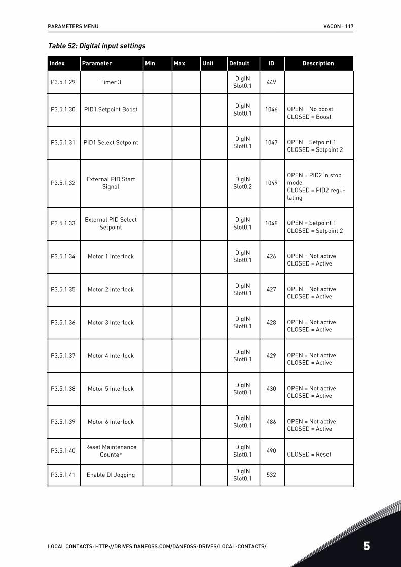
Table 52: Digital input settings
Index Parameter Min Max Unit Default ID Description
P3.5.1.29 Timer 3 DigINSlot0.1 449
P3.5.1.30 PID1 Setpoint Boost DigINSlot0.1 1046 OPEN = No boost
CLOSED = Boost
P3.5.1.31 PID1 Select Setpoint DigINSlot0.1 1047 OPEN = Setpoint 1
CLOSED = Setpoint 2
P3.5.1.32 External PID StartSignal
DigINSlot0.2 1049
OPEN = PID2 in stopmodeCLOSED = PID2 regu-lating
P3.5.1.33 External PID SelectSetpoint
DigINSlot0.1 1048 OPEN = Setpoint 1
CLOSED = Setpoint 2
P3.5.1.34 Motor 1 Interlock DigINSlot0.1 426 OPEN = Not active
CLOSED = Active
P3.5.1.35 Motor 2 Interlock DigINSlot0.1 427 OPEN = Not active
CLOSED = Active
P3.5.1.36 Motor 3 Interlock DigINSlot0.1 428 OPEN = Not active
CLOSED = Active
P3.5.1.37 Motor 4 Interlock DigINSlot0.1 429 OPEN = Not active
CLOSED = Active
P3.5.1.38 Motor 5 Interlock DigINSlot0.1 430 OPEN = Not active
CLOSED = Active
P3.5.1.39 Motor 6 Interlock DigINSlot0.1 486 OPEN = Not active
CLOSED = Active
P3.5.1.40 Reset MaintenanceCounter
DigINSlot0.1 490 CLOSED = Reset
P3.5.1.41 Enable DI Jogging DigINSlot0.1 532
PARAMETERS MENU VACON · 117
LOCAL CONTACTS: HTTP://DRIVES.DANFOSS.COM/DANFOSS-DRIVES/LOCAL-CONTACTS/ 5
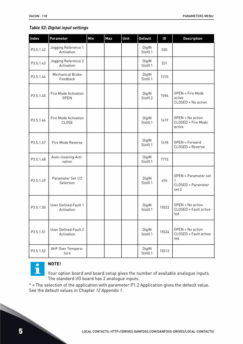
Table 52: Digital input settings
Index Parameter Min Max Unit Default ID Description
P3.5.1.42 Jogging Reference 1Activation
DigINSlot0.1 530
P3.5.1.43 Jogging Reference 2Activation
DigINSlot0.1 531
P3.5.1.44 Mechanical BrakeFeedback
DigINSlot0.1 1210
P3.5.1.45 Fire Mode ActivationOPEN
DigINSlot0.2 1596 OPEN = Fire Mode
activeCLOSED = No action
P3.5.1.46 Fire Mode ActivationCLOSE
DigINSlot0.1 1619 OPEN = No action
CLOSED = Fire Modeactive
P3.5.1.47 Fire Mode Reverse DigINSlot0.1 1618 OPEN = Forward
CLOSED = Reverse
P3.5.1.48 Auto-cleaning Acti-vation
DigINSlot0.1 1715
P3.5.1.49 Parameter Set 1/2Selection
DigINSlot0.1 496
OPEN = Parameter set1CLOSED = Parameterset 2
P3.5.1.50 User Defined Fault 1Activation
DigINSlot0.1 15523 OPEN = No action
CLOSED = Fault activa-ted
P3.5.1.51 User Defined Fault 2Activation
DigINSlot0.1 15524 OPEN = No action
CLOSED = Fault activa-ted
P3.5.1.52 AHF Over Tempera-ture
DigINSlot0.1 15513
NOTE!
Your option board and board setup gives the number of available analogue inputs.The standard I/O board has 2 analogue inputs.
* = The selection of the application with parameter P1.2 Application gives the default value.See the default values in Chapter 12 Appendix 1.
VACON · 118 PARAMETERS MENU
5 LOCAL CONTACTS: HTTP://DRIVES.DANFOSS.COM/DANFOSS-DRIVES/LOCAL-CONTACTS/
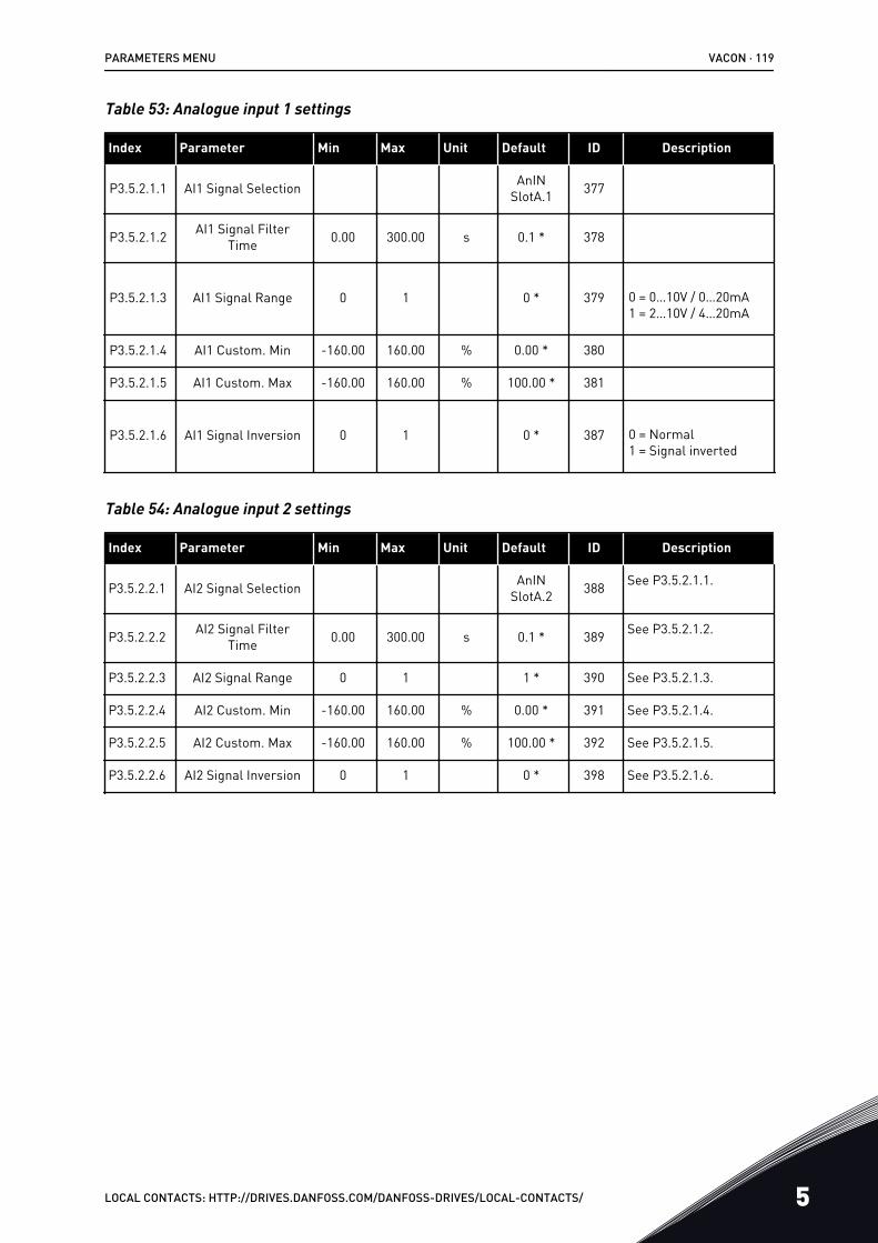
Table 53: Analogue input 1 settings
Index Parameter Min Max Unit Default ID Description
P3.5.2.1.1 AI1 Signal Selection AnINSlotA.1 377
P3.5.2.1.2 AI1 Signal FilterTime 0.00 300.00 s 0.1 * 378
P3.5.2.1.3 AI1 Signal Range 0 1 0 * 379 0 = 0…10V / 0…20mA1 = 2…10V / 4…20mA
P3.5.2.1.4 AI1 Custom. Min -160.00 160.00 % 0.00 * 380
P3.5.2.1.5 AI1 Custom. Max -160.00 160.00 % 100.00 * 381
P3.5.2.1.6 AI1 Signal Inversion 0 1 0 * 387 0 = Normal1 = Signal inverted
Table 54: Analogue input 2 settings
Index Parameter Min Max Unit Default ID Description
P3.5.2.2.1 AI2 Signal Selection AnINSlotA.2 388 See P3.5.2.1.1.
P3.5.2.2.2 AI2 Signal FilterTime 0.00 300.00 s 0.1 * 389 See P3.5.2.1.2.
P3.5.2.2.3 AI2 Signal Range 0 1 1 * 390 See P3.5.2.1.3.
P3.5.2.2.4 AI2 Custom. Min -160.00 160.00 % 0.00 * 391 See P3.5.2.1.4.
P3.5.2.2.5 AI2 Custom. Max -160.00 160.00 % 100.00 * 392 See P3.5.2.1.5.
P3.5.2.2.6 AI2 Signal Inversion 0 1 0 * 398 See P3.5.2.1.6.
PARAMETERS MENU VACON · 119
LOCAL CONTACTS: HTTP://DRIVES.DANFOSS.COM/DANFOSS-DRIVES/LOCAL-CONTACTS/ 5
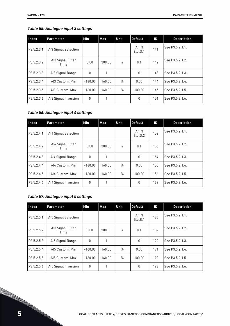
Table 55: Analogue input 3 settings
Index Parameter Min Max Unit Default ID Description
P3.5.2.3.1 AI3 Signal Selection AnINSlotD.1 141 See P3.5.2.1.1.
P3.5.2.3.2 AI3 Signal FilterTime 0.00 300.00 s 0.1 142 See P3.5.2.1.2.
P3.5.2.3.3 AI3 Signal Range 0 1 0 143 See P3.5.2.1.3.
P3.5.2.3.4 AI3 Custom. Min -160.00 160.00 % 0.00 144 See P3.5.2.1.4.
P3.5.2.3.5 AI3 Custom. Max -160.00 160.00 % 100.00 145 See P3.5.2.1.5.
P3.5.2.3.6 AI3 Signal Inversion 0 1 0 151 See P3.5.2.1.6.
Table 56: Analogue input 4 settings
Index Parameter Min Max Unit Default ID Description
P3.5.2.4.1 AI4 Signal Selection AnINSlotD.2 152 See P3.5.2.1.1.
P3.5.2.4.2 AI4 Signal FilterTime 0.00 300.00 s 0.1 153 See P3.5.2.1.2.
P3.5.2.4.3 AI4 Signal Range 0 1 0 154 See P3.5.2.1.3.
P3.5.2.4.4 AI4 Custom. Min -160.00 160.00 % 0.00 155 See P3.5.2.1.4.
P3.5.2.4.5 AI4 Custom. Max -160.00 160.00 % 100.00 156 See P3.5.2.1.5.
P3.5.2.4.6 AI4 Signal Inversion 0 1 0 162 See P3.5.2.1.6.
Table 57: Analogue input 5 settings
Index Parameter Min Max Unit Default ID Description
P3.5.2.5.1 AI5 Signal Selection AnINSlotE.1 188 See P3.5.2.1.1.
P3.5.2.5.2 AI5 Signal FilterTime 0.00 300.00 s 0.1 189 See P3.5.2.1.2.
P3.5.2.5.3 AI5 Signal Range 0 1 0 190 See P3.5.2.1.3.
P3.5.2.5.4 AI5 Custom. Min -160.00 160.00 % 0.00 191 See P3.5.2.1.4.
P3.5.2.5.5 AI5 Custom. Max -160.00 160.00 % 100.00 192 See P3.5.2.1.5.
P3.5.2.5.6 AI5 Signal Inversion 0 1 0 198 See P3.5.2.1.6.
VACON · 120 PARAMETERS MENU
5 LOCAL CONTACTS: HTTP://DRIVES.DANFOSS.COM/DANFOSS-DRIVES/LOCAL-CONTACTS/
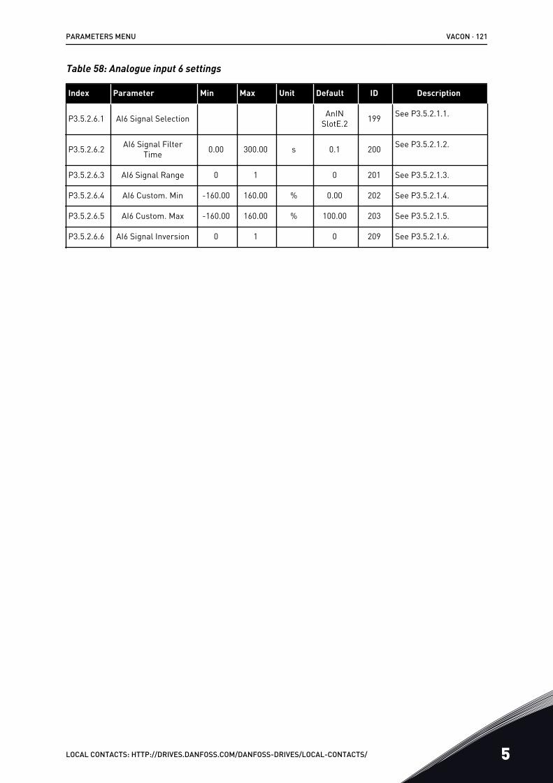
Table 58: Analogue input 6 settings
Index Parameter Min Max Unit Default ID Description
P3.5.2.6.1 AI6 Signal Selection AnINSlotE.2 199 See P3.5.2.1.1.
P3.5.2.6.2 AI6 Signal FilterTime 0.00 300.00 s 0.1 200 See P3.5.2.1.2.
P3.5.2.6.3 AI6 Signal Range 0 1 0 201 See P3.5.2.1.3.
P3.5.2.6.4 AI6 Custom. Min -160.00 160.00 % 0.00 202 See P3.5.2.1.4.
P3.5.2.6.5 AI6 Custom. Max -160.00 160.00 % 100.00 203 See P3.5.2.1.5.
P3.5.2.6.6 AI6 Signal Inversion 0 1 0 209 See P3.5.2.1.6.
PARAMETERS MENU VACON · 121
LOCAL CONTACTS: HTTP://DRIVES.DANFOSS.COM/DANFOSS-DRIVES/LOCAL-CONTACTS/ 5
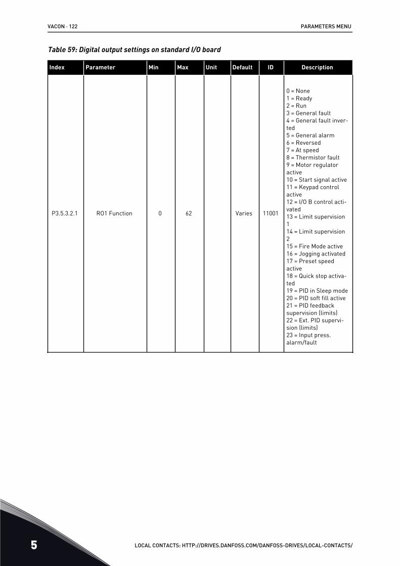
Table 59: Digital output settings on standard I/O board
Index Parameter Min Max Unit Default ID Description
P3.5.3.2.1 RO1 Function 0 62 Varies 11001
0 = None1 = Ready2 = Run3 = General fault4 = General fault inver-ted5 = General alarm6 = Reversed7 = At speed8 = Thermistor fault9 = Motor regulatoractive10 = Start signal active11 = Keypad controlactive12 = I/O B control acti-vated13 = Limit supervision114 = Limit supervision215 = Fire Mode active16 = Jogging activated17 = Preset speedactive18 = Quick stop activa-ted19 = PID in Sleep mode20 = PID soft fill active21 = PID feedbacksupervision (limits)22 = Ext. PID supervi-sion (limits)23 = Input press.alarm/fault
VACON · 122 PARAMETERS MENU
5 LOCAL CONTACTS: HTTP://DRIVES.DANFOSS.COM/DANFOSS-DRIVES/LOCAL-CONTACTS/
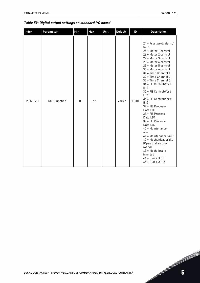
Table 59: Digital output settings on standard I/O board
Index Parameter Min Max Unit Default ID Description
P3.5.3.2.1 RO1 Function 0 62 Varies 11001
24 = Frost prot. alarm/fault25 = Motor 1 control26 = Motor 2 control27 = Motor 3 control28 = Motor 4 control29 = Motor 5 control30 = Motor 6 control31 = Time Channel 132 = Time Channel 233 = Time Channel 334 = FB ControlWordB1335 = FB ControlWordB1436 = FB ControlWordB1537 = FB Process-Data1.B038 = FB Process-Data1.B139 = FB Process-Data1.B240 = Maintenancealarm41 = Maintenance fault42 = Mechanical brake(Open brake com-mand)43 = Mech. brakeinverted44 = Block Out.145 = Block Out.2
PARAMETERS MENU VACON · 123
LOCAL CONTACTS: HTTP://DRIVES.DANFOSS.COM/DANFOSS-DRIVES/LOCAL-CONTACTS/ 5
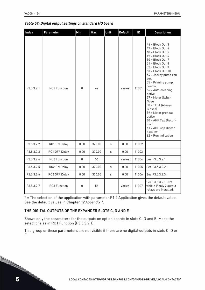
Table 59: Digital output settings on standard I/O board
Index Parameter Min Max Unit Default ID Description
P3.5.3.2.1 RO1 Function 0 62 Varies 11001
46 = Block Out.347 = Block Out.448 = Block Out.549 = Block Out.650 = Block Out.751 = Block Out.852 = Block Out.953 = Block Out.1054 = Jockey pump con-trol55 = Priming pumpcontrol56 = Auto-cleaningactive57 = Motor SwitchOpen58 = TEST (AlwaysClosed)59 = Motor preheatactive60 = AHF Cap Discon-nect61 = AHF Cap Discon-nect Inv62 = Run Indication
P3.5.3.2.2 RO1 ON Delay 0.00 320.00 s 0.00 11002
P3.5.3.2.3 RO1 OFF Delay 0.00 320.00 s 0.00 11003
P3.5.3.2.4 RO2 Function 0 56 Varies 11004 See P3.5.3.2.1.
P3.5.3.2.5 RO2 ON Delay 0.00 320.00 s 0.00 11005 See P3.5.3.2.2.
P3.5.3.2.6 RO2 OFF Delay 0.00 320.00 s 0.00 11006 See P3.5.3.2.3.
P3.5.3.2.7 RO3 Function 0 56 Varies 11007See P3.5.3.2.1. Notvisible if only 2 outputrelays are installed.
* = The selection of the application with parameter P1.2 Application gives the default value.See the default values in Chapter 12 Appendix 1.
THE DIGITAL OUTPUTS OF THE EXPANDER SLOTS C, D AND E
Shows only the parameters for the outputs on option boards in slots C, D and E. Make theselections as in RO1 Function (P3.5.3.2.1).
This group or these parameters are not visible if there are no digital outputs in slots C, D orE.
VACON · 124 PARAMETERS MENU
5 LOCAL CONTACTS: HTTP://DRIVES.DANFOSS.COM/DANFOSS-DRIVES/LOCAL-CONTACTS/
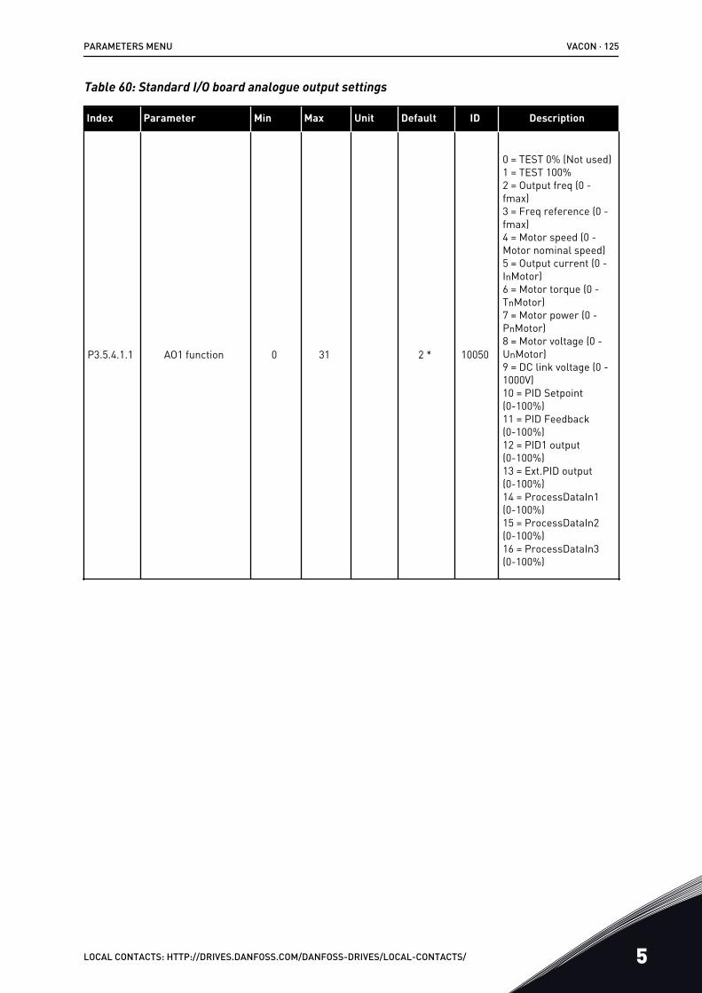
Table 60: Standard I/O board analogue output settings
Index Parameter Min Max Unit Default ID Description
P3.5.4.1.1 AO1 function 0 31 2 * 10050
0 = TEST 0% (Not used)1 = TEST 100%2 = Output freq (0 -fmax)3 = Freq reference (0 -fmax)4 = Motor speed (0 -Motor nominal speed)5 = Output current (0 -InMotor)6 = Motor torque (0 -TnMotor)7 = Motor power (0 -PnMotor)8 = Motor voltage (0 -UnMotor)9 = DC link voltage (0 -1000V)10 = PID Setpoint(0-100%)11 = PID Feedback(0-100%)12 = PID1 output(0-100%)13 = Ext.PID output(0-100%)14 = ProcessDataIn1(0-100%)15 = ProcessDataIn2(0-100%)16 = ProcessDataIn3(0-100%)
PARAMETERS MENU VACON · 125
LOCAL CONTACTS: HTTP://DRIVES.DANFOSS.COM/DANFOSS-DRIVES/LOCAL-CONTACTS/ 5
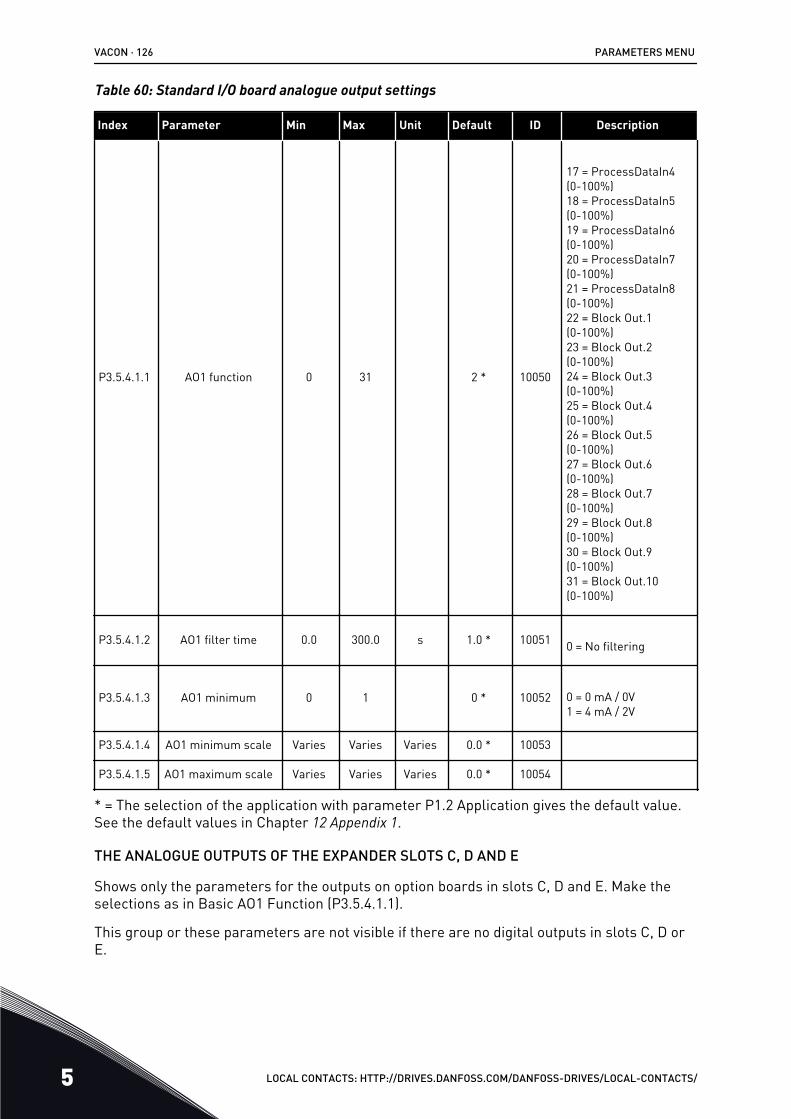
Table 60: Standard I/O board analogue output settings
Index Parameter Min Max Unit Default ID Description
P3.5.4.1.1 AO1 function 0 31 2 * 10050
17 = ProcessDataIn4(0-100%)18 = ProcessDataIn5(0-100%)19 = ProcessDataIn6(0-100%)20 = ProcessDataIn7(0-100%)21 = ProcessDataIn8(0-100%)22 = Block Out.1(0-100%)23 = Block Out.2(0-100%)24 = Block Out.3(0-100%)25 = Block Out.4(0-100%)26 = Block Out.5(0-100%)27 = Block Out.6(0-100%)28 = Block Out.7(0-100%)29 = Block Out.8(0-100%)30 = Block Out.9(0-100%)31 = Block Out.10(0-100%)
P3.5.4.1.2 AO1 filter time 0.0 300.0 s 1.0 * 10051 0 = No filtering
P3.5.4.1.3 AO1 minimum 0 1 0 * 10052 0 = 0 mA / 0V1 = 4 mA / 2V
P3.5.4.1.4 AO1 minimum scale Varies Varies Varies 0.0 * 10053
P3.5.4.1.5 AO1 maximum scale Varies Varies Varies 0.0 * 10054
* = The selection of the application with parameter P1.2 Application gives the default value.See the default values in Chapter 12 Appendix 1.
THE ANALOGUE OUTPUTS OF THE EXPANDER SLOTS C, D AND E
Shows only the parameters for the outputs on option boards in slots C, D and E. Make theselections as in Basic AO1 Function (P3.5.4.1.1).
This group or these parameters are not visible if there are no digital outputs in slots C, D orE.
VACON · 126 PARAMETERS MENU
5 LOCAL CONTACTS: HTTP://DRIVES.DANFOSS.COM/DANFOSS-DRIVES/LOCAL-CONTACTS/
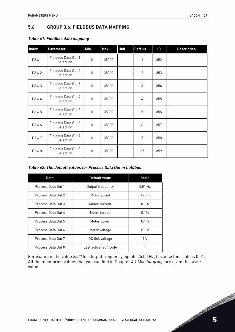
5.6 GROUP 3.6: FIELDBUS DATA MAPPING
Table 61: Fieldbus data mapping
Index Parameter Min Max Unit Default ID Description
P3.6.1 Fieldbus Data Out 1Selection 0 35000 1 852
P3.6.2 Fieldbus Data Out 2Selection 0 35000 2 853
P3.6.3 Fieldbus Data Out 3Selection 0 35000 3 854
P3.6.4 Fieldbus Data Out 4Selection 0 35000 4 855
P3.6.5 Fieldbus Data Out 5Selection 0 35000 5 856
P3.6.6 Fieldbus Data Out 6Selection 0 35000 6 857
P3.6.7 Fieldbus Data Out 7Selection 0 35000 7 858
P3.6.8 Fieldbus Data Out 8Selection 0 35000 37 859
Table 62: The default values for Process Data Out in fieldbus
Data Default value Scale
Process Data Out 1 Output frequency 0.01 Hz
Process Data Out 2 Motor speed 1 rpm
Process Data Out 3 Motor current 0.1 A
Process Data Out 4 Motor torque 0.1%
Process Data Out 5 Motor power 0.1%
Process Data Out 6 Motor voltage 0.1 V
Process Data Out 7 DC link voltage 1 V
Process Data Out 8 Last active fault code 1
For example, the value 2500 for Output frequency equals 25.00 Hz, because the scale is 0.01.All the monitoring values that you can find in Chapter 4.1 Monitor group are given the scalevalue.
PARAMETERS MENU VACON · 127
LOCAL CONTACTS: HTTP://DRIVES.DANFOSS.COM/DANFOSS-DRIVES/LOCAL-CONTACTS/ 5
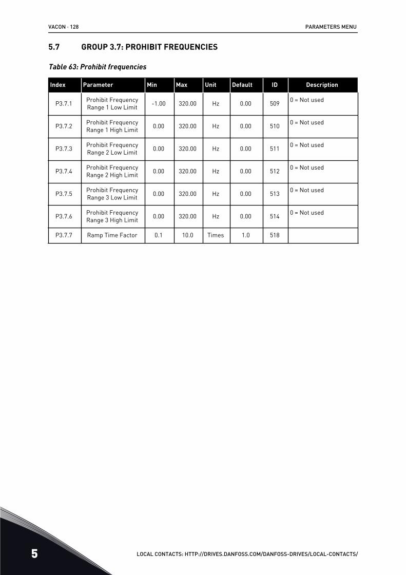
5.7 GROUP 3.7: PROHIBIT FREQUENCIES
Table 63: Prohibit frequencies
Index Parameter Min Max Unit Default ID Description
P3.7.1 Prohibit FrequencyRange 1 Low Limit -1.00 320.00 Hz 0.00 509 0 = Not used
P3.7.2 Prohibit FrequencyRange 1 High Limit 0.00 320.00 Hz 0.00 510 0 = Not used
P3.7.3 Prohibit FrequencyRange 2 Low Limit 0.00 320.00 Hz 0.00 511 0 = Not used
P3.7.4 Prohibit FrequencyRange 2 High Limit 0.00 320.00 Hz 0.00 512 0 = Not used
P3.7.5 Prohibit FrequencyRange 3 Low Limit 0.00 320.00 Hz 0.00 513 0 = Not used
P3.7.6 Prohibit FrequencyRange 3 High Limit 0.00 320.00 Hz 0.00 514 0 = Not used
P3.7.7 Ramp Time Factor 0.1 10.0 Times 1.0 518
VACON · 128 PARAMETERS MENU
5 LOCAL CONTACTS: HTTP://DRIVES.DANFOSS.COM/DANFOSS-DRIVES/LOCAL-CONTACTS/
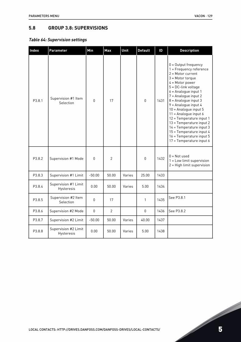
5.8 GROUP 3.8: SUPERVISIONS
Table 64: Supervision settings
Index Parameter Min Max Unit Default ID Description
P3.8.1 Supervision #1 ItemSelection 0 17 0 1431
0 = Output frequency1 = Frequency reference2 = Motor current3 = Motor torque4 = Motor power5 = DC-link voltage6 = Analogue input 17 = Analogue input 28 = Analogue input 39 = Analogue input 410 = Analogue input 511 = Analogue input 612 = Temperature input 113 = Temperature input 214 = Temperature input 315 = Temperature input 416 = Temperature input 517 = Temperature input 6
P3.8.2 Supervision #1 Mode 0 2 0 1432 0 = Not used1 = Low limit supervision2 = High limit supervision
P3.8.3 Supervision #1 Limit -50.00 50.00 Varies 25.00 1433
P3.8.4 Supervision #1 LimitHysteresis 0.00 50.00 Varies 5.00 1434
P3.8.5 Supervision #2 ItemSelection 0 17 1 1435 See P3.8.1
P3.8.6 Supervision #2 Mode 0 2 0 1436 See P3.8.2
P3.8.7 Supervision #2 Limit -50.00 50.00 Varies 40.00 1437
P3.8.8 Supervision #2 LimitHysteresis 0.00 50.00 Varies 5.00 1438
PARAMETERS MENU VACON · 129
LOCAL CONTACTS: HTTP://DRIVES.DANFOSS.COM/DANFOSS-DRIVES/LOCAL-CONTACTS/ 5
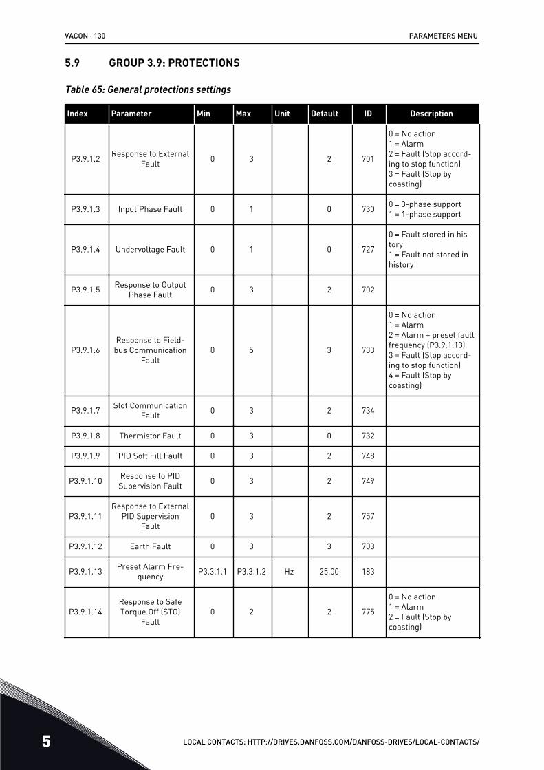
5.9 GROUP 3.9: PROTECTIONS
Table 65: General protections settings
Index Parameter Min Max Unit Default ID Description
P3.9.1.2 Response to ExternalFault 0 3 2 701
0 = No action1 = Alarm2 = Fault (Stop accord-ing to stop function)3 = Fault (Stop bycoasting)
P3.9.1.3 Input Phase Fault 0 1 0 730 0 = 3-phase support1 = 1-phase support
P3.9.1.4 Undervoltage Fault 0 1 0 727
0 = Fault stored in his-tory1 = Fault not stored inhistory
P3.9.1.5 Response to OutputPhase Fault 0 3 2 702
P3.9.1.6Response to Field-
bus CommunicationFault
0 5 3 733
0 = No action1 = Alarm2 = Alarm + preset faultfrequency (P3.9.1.13)3 = Fault (Stop accord-ing to stop function)4 = Fault (Stop bycoasting)
P3.9.1.7 Slot CommunicationFault 0 3 2 734
P3.9.1.8 Thermistor Fault 0 3 0 732
P3.9.1.9 PID Soft Fill Fault 0 3 2 748
P3.9.1.10 Response to PIDSupervision Fault 0 3 2 749
P3.9.1.11Response to External
PID SupervisionFault
0 3 2 757
P3.9.1.12 Earth Fault 0 3 3 703
P3.9.1.13 Preset Alarm Fre-quency P3.3.1.1 P3.3.1.2 Hz 25.00 183
P3.9.1.14Response to SafeTorque Off (STO)
Fault0 2 2 775
0 = No action1 = Alarm2 = Fault (Stop bycoasting)
VACON · 130 PARAMETERS MENU
5 LOCAL CONTACTS: HTTP://DRIVES.DANFOSS.COM/DANFOSS-DRIVES/LOCAL-CONTACTS/

Table 65: General protections settings
Index Parameter Min Max Unit Default ID Description
P3.9.1.15 Startup PreventedFault 0 1 0 15593 0 = Fault
1 = No action
Table 66: Motor thermal protection settings
Index Parameter Min Max Unit Default ID Description
P3.9.2.1 Motor Thermal Pro-tection 0 3 2 704
0 = No action1 = Alarm2 = Fault (Stop by stopmode)3 = Fault (Stop bycoasting)
P3.9.2.2 Ambient Tempera-ture -20.0 100.0 °C 40.0 705
P3.9.2.3 Zero Speed CoolingFactor 5.0 150.0 % Varies 706
P3.9.2.4 Motor Thermal TimeConstant 1 200 min Varies 707
P3.9.2.5 Motor Thermal Load-ability 10 150 % 100 708
Table 67: Motor stall protection settings
Index Parameter Min Max Unit Default ID Description
P3.9.3.1 Motor Stall Fault 0 3 0 709
0 = No action1 = Alarm2 = Fault (Stop accord-ing to stop mode)3 = Fault (Stop bycoasting)
P3.9.3.2 Stall Current 0.00 5.2 A 3.7 710
P3.9.3.3 Stall Time Limit 1.00 120.00 s 15.00 711
P3.9.3.4 Stall Frequency Limit 1.00 P3.3.1.2 Hz 25.00 712
PARAMETERS MENU VACON · 131
LOCAL CONTACTS: HTTP://DRIVES.DANFOSS.COM/DANFOSS-DRIVES/LOCAL-CONTACTS/ 5
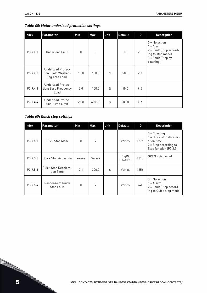
Table 68: Motor underload protection settings
Index Parameter Min Max Unit Default ID Description
P3.9.4.1 Underload Fault 0 3 0 713
0 = No action1 = Alarm2 = Fault (Stop accord-ing to stop mode)3 = Fault (Stop bycoasting)
P3.9.4.2Underload Protec-tion: Field Weaken-
ing Area Load10.0 150.0 % 50.0 714
P3.9.4.3Underload Protec-
tion: Zero FrequencyLoad
5.0 150.0 % 10.0 715
P3.9.4.4 Underload Protec-tion: Time Limit 2.00 600.00 s 20.00 716
Table 69: Quick stop settings
Index Parameter Min Max Unit Default ID Description
P3.9.5.1 Quick Stop Mode 0 2 Varies 1276
0 = Coasting1 = Quick stop deceler-ation time2 = Stop according toStop function (P3.2.5)
P3.9.5.2 Quick Stop Activation Varies Varies DigINSlot0.2 1213 OPEN = Activated
P3.9.5.3 Quick Stop Decelera-tion Time 0.1 300.0 s Varies 1256
P3.9.5.4 Response to QuickStop Fault 0 2 Varies 744
0 = No action1 = Alarm2 = Fault (Stop accord-ing to Quick stop mode)
VACON · 132 PARAMETERS MENU
5 LOCAL CONTACTS: HTTP://DRIVES.DANFOSS.COM/DANFOSS-DRIVES/LOCAL-CONTACTS/
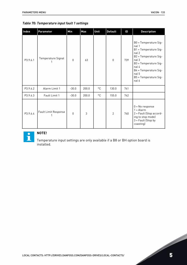
Table 70: Temperature input fault 1 settings
Index Parameter Min Max Unit Default ID Description
P3.9.6.1 Temperature Signal1 0 63 0 739
B0 = Temperature Sig-nal 1B1 = Temperature Sig-nal 2B2 = Temperature Sig-nal 3B3 = Temperature Sig-nal 4B4 = Temperature Sig-nal 5B5 = Temperature Sig-nal 6
P3.9.6.2 Alarm Limit 1 -30.0 200.0 °C 130.0 741
P3.9.6.3 Fault Limit 1 -30.0 200.0 °C 155.0 742
P3.9.6.4 Fault Limit Response1 0 3 2 740
0 = No response1 = Alarm2 = Fault (Stop accord-ing to stop mode)3 = Fault (Stop bycoasting)
NOTE!
Temperature input settings are only available if a B8 or BH option board isinstalled.
PARAMETERS MENU VACON · 133
LOCAL CONTACTS: HTTP://DRIVES.DANFOSS.COM/DANFOSS-DRIVES/LOCAL-CONTACTS/ 5
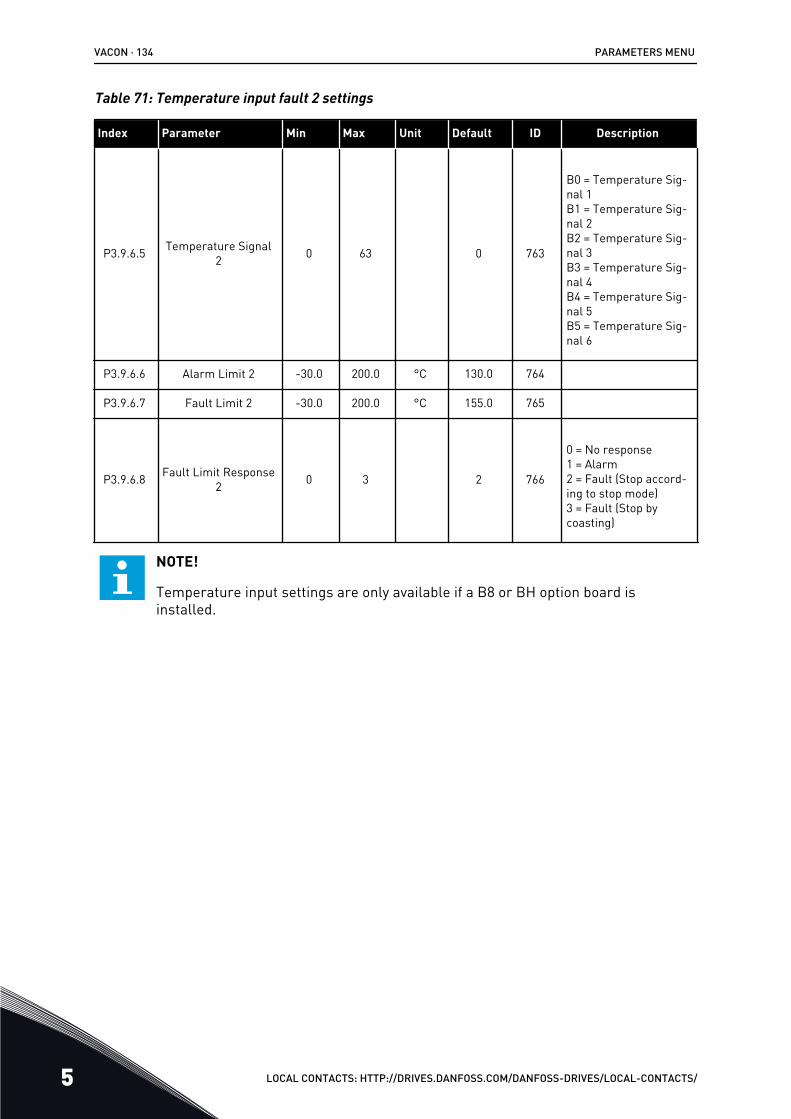
Table 71: Temperature input fault 2 settings
Index Parameter Min Max Unit Default ID Description
P3.9.6.5 Temperature Signal2 0 63 0 763
B0 = Temperature Sig-nal 1B1 = Temperature Sig-nal 2B2 = Temperature Sig-nal 3B3 = Temperature Sig-nal 4B4 = Temperature Sig-nal 5B5 = Temperature Sig-nal 6
P3.9.6.6 Alarm Limit 2 -30.0 200.0 °C 130.0 764
P3.9.6.7 Fault Limit 2 -30.0 200.0 °C 155.0 765
P3.9.6.8 Fault Limit Response2 0 3 2 766
0 = No response1 = Alarm2 = Fault (Stop accord-ing to stop mode)3 = Fault (Stop bycoasting)
NOTE!
Temperature input settings are only available if a B8 or BH option board isinstalled.
VACON · 134 PARAMETERS MENU
5 LOCAL CONTACTS: HTTP://DRIVES.DANFOSS.COM/DANFOSS-DRIVES/LOCAL-CONTACTS/
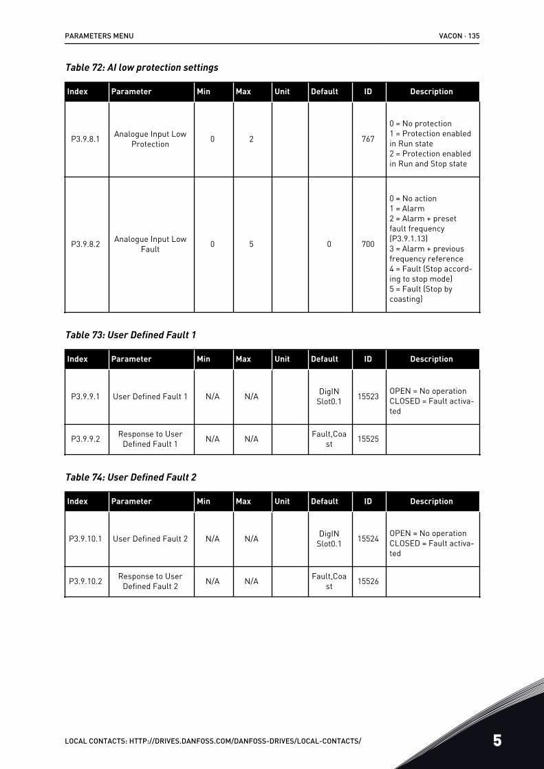
Table 72: AI low protection settings
Index Parameter Min Max Unit Default ID Description
P3.9.8.1 Analogue Input LowProtection 0 2 767
0 = No protection1 = Protection enabledin Run state2 = Protection enabledin Run and Stop state
P3.9.8.2 Analogue Input LowFault 0 5 0 700
0 = No action1 = Alarm2 = Alarm + presetfault frequency(P3.9.1.13)3 = Alarm + previousfrequency reference4 = Fault (Stop accord-ing to stop mode)5 = Fault (Stop bycoasting)
Table 73: User Defined Fault 1
Index Parameter Min Max Unit Default ID Description
P3.9.9.1 User Defined Fault 1 N/A N/A DigINSlot0.1 15523 OPEN = No operation
CLOSED = Fault activa-ted
P3.9.9.2 Response to UserDefined Fault 1 N/A N/A Fault,Coa
st 15525
Table 74: User Defined Fault 2
Index Parameter Min Max Unit Default ID Description
P3.9.10.1 User Defined Fault 2 N/A N/A DigINSlot0.1 15524 OPEN = No operation
CLOSED = Fault activa-ted
P3.9.10.2 Response to UserDefined Fault 2 N/A N/A Fault,Coa
st 15526
PARAMETERS MENU VACON · 135
LOCAL CONTACTS: HTTP://DRIVES.DANFOSS.COM/DANFOSS-DRIVES/LOCAL-CONTACTS/ 5
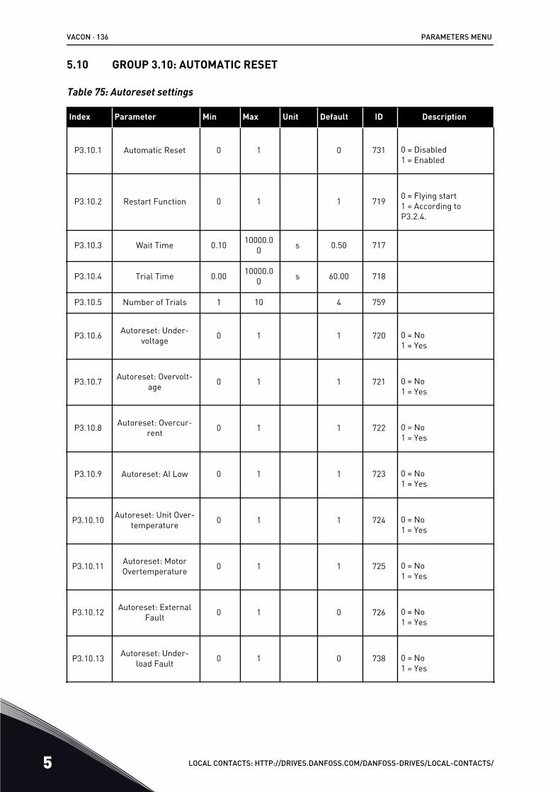
5.10 GROUP 3.10: AUTOMATIC RESET
Table 75: Autoreset settings
Index Parameter Min Max Unit Default ID Description
P3.10.1 Automatic Reset 0 1 0 731 0 = Disabled1 = Enabled
P3.10.2 Restart Function 0 1 1 719 0 = Flying start1 = According toP3.2.4.
P3.10.3 Wait Time 0.10 10000.00 s 0.50 717
P3.10.4 Trial Time 0.00 10000.00 s 60.00 718
P3.10.5 Number of Trials 1 10 4 759
P3.10.6 Autoreset: Under-voltage 0 1 1 720 0 = No
1 = Yes
P3.10.7 Autoreset: Overvolt-age 0 1 1 721 0 = No
1 = Yes
P3.10.8 Autoreset: Overcur-rent 0 1 1 722 0 = No
1 = Yes
P3.10.9 Autoreset: AI Low 0 1 1 723 0 = No1 = Yes
P3.10.10 Autoreset: Unit Over-temperature 0 1 1 724 0 = No
1 = Yes
P3.10.11 Autoreset: MotorOvertemperature 0 1 1 725 0 = No
1 = Yes
P3.10.12 Autoreset: ExternalFault 0 1 0 726 0 = No
1 = Yes
P3.10.13 Autoreset: Under-load Fault 0 1 0 738 0 = No
1 = Yes
VACON · 136 PARAMETERS MENU
5 LOCAL CONTACTS: HTTP://DRIVES.DANFOSS.COM/DANFOSS-DRIVES/LOCAL-CONTACTS/
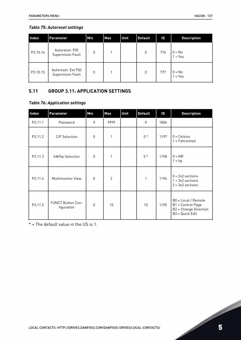
Table 75: Autoreset settings
Index Parameter Min Max Unit Default ID Description
P3.10.14 Autoreset: PIDSupervision Fault 0 1 0 776 0 = No
1 = Yes
P3.10.15 Autoreset: Ext PIDSupervision Fault 0 1 0 777 0 = No
1 = Yes
5.11 GROUP 3.11: APPLICATION SETTINGS
Table 76: Application settings
Index Parameter Min Max Unit Default ID Description
P3.11.1 Password 0 9999 0 1806
P3.11.2 C/F Selection 0 1 0 * 1197 0 = Celsius1 = Fahrenheit
P3.11.3 kW/hp Selection 0 1 0 * 1198 0 = kW1 = hp
P3.11.4 Multimonitor View 0 2 1 1196 0 = 2x2 sections1 = 3x2 sections2 = 3x3 sections
P3.11.5 FUNCT Button Con-figuration 0 15 15 1195
B0 = Local / RemoteB1 = Control PageB2 = Change DirectionB3 = Quick Edit
* = The default value in the US is 1.
PARAMETERS MENU VACON · 137
LOCAL CONTACTS: HTTP://DRIVES.DANFOSS.COM/DANFOSS-DRIVES/LOCAL-CONTACTS/ 5
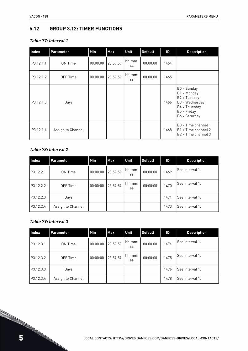
5.12 GROUP 3.12: TIMER FUNCTIONS
Table 77: Interval 1
Index Parameter Min Max Unit Default ID Description
P3.12.1.1 ON Time 00:00:00 23:59:59 hh:mm:ss 00:00:00 1464
P3.12.1.2 OFF Time 00:00:00 23:59:59 hh:mm:ss 00:00:00 1465
P3.12.1.3 Days 1466
B0 = SundayB1 = MondayB2 = TuesdayB3 = WednesdayB4 = ThursdayB5 = FridayB6 = Saturday
P3.12.1.4 Assign to Channel 1468B0 = Time channel 1B1 = Time channel 2B2 = Time channel 3
Table 78: Interval 2
Index Parameter Min Max Unit Default ID Description
P3.12.2.1 ON Time 00:00:00 23:59:59 hh:mm:ss 00:00:00 1469 See Interval 1.
P3.12.2.2 OFF Time 00:00:00 23:59:59 hh:mm:ss 00:00:00 1470 See Interval 1.
P3.12.2.3 Days 1471 See Interval 1.
P3.12.2.4 Assign to Channel 1473 See Interval 1.
Table 79: Interval 3
Index Parameter Min Max Unit Default ID Description
P3.12.3.1 ON Time 00:00:00 23:59:59 hh:mm:ss 00:00:00 1474 See Interval 1.
P3.12.3.2 OFF Time 00:00:00 23:59:59 hh:mm:ss 00:00:00 1475 See Interval 1.
P3.12.3.3 Days 1476 See Interval 1.
P3.12.3.4 Assign to Channel 1478 See Interval 1.
VACON · 138 PARAMETERS MENU
5 LOCAL CONTACTS: HTTP://DRIVES.DANFOSS.COM/DANFOSS-DRIVES/LOCAL-CONTACTS/
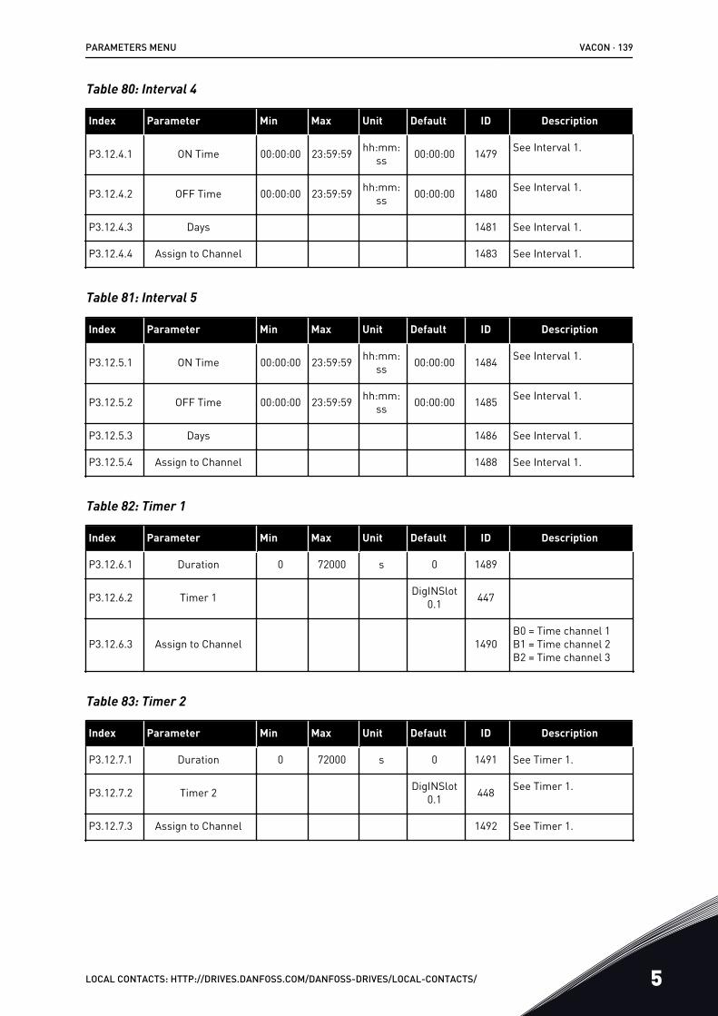
Table 80: Interval 4
Index Parameter Min Max Unit Default ID Description
P3.12.4.1 ON Time 00:00:00 23:59:59 hh:mm:ss 00:00:00 1479 See Interval 1.
P3.12.4.2 OFF Time 00:00:00 23:59:59 hh:mm:ss 00:00:00 1480 See Interval 1.
P3.12.4.3 Days 1481 See Interval 1.
P3.12.4.4 Assign to Channel 1483 See Interval 1.
Table 81: Interval 5
Index Parameter Min Max Unit Default ID Description
P3.12.5.1 ON Time 00:00:00 23:59:59 hh:mm:ss 00:00:00 1484 See Interval 1.
P3.12.5.2 OFF Time 00:00:00 23:59:59 hh:mm:ss 00:00:00 1485 See Interval 1.
P3.12.5.3 Days 1486 See Interval 1.
P3.12.5.4 Assign to Channel 1488 See Interval 1.
Table 82: Timer 1
Index Parameter Min Max Unit Default ID Description
P3.12.6.1 Duration 0 72000 s 0 1489
P3.12.6.2 Timer 1 DigINSlot0.1 447
P3.12.6.3 Assign to Channel 1490B0 = Time channel 1B1 = Time channel 2B2 = Time channel 3
Table 83: Timer 2
Index Parameter Min Max Unit Default ID Description
P3.12.7.1 Duration 0 72000 s 0 1491 See Timer 1.
P3.12.7.2 Timer 2 DigINSlot0.1 448 See Timer 1.
P3.12.7.3 Assign to Channel 1492 See Timer 1.
PARAMETERS MENU VACON · 139
LOCAL CONTACTS: HTTP://DRIVES.DANFOSS.COM/DANFOSS-DRIVES/LOCAL-CONTACTS/ 5
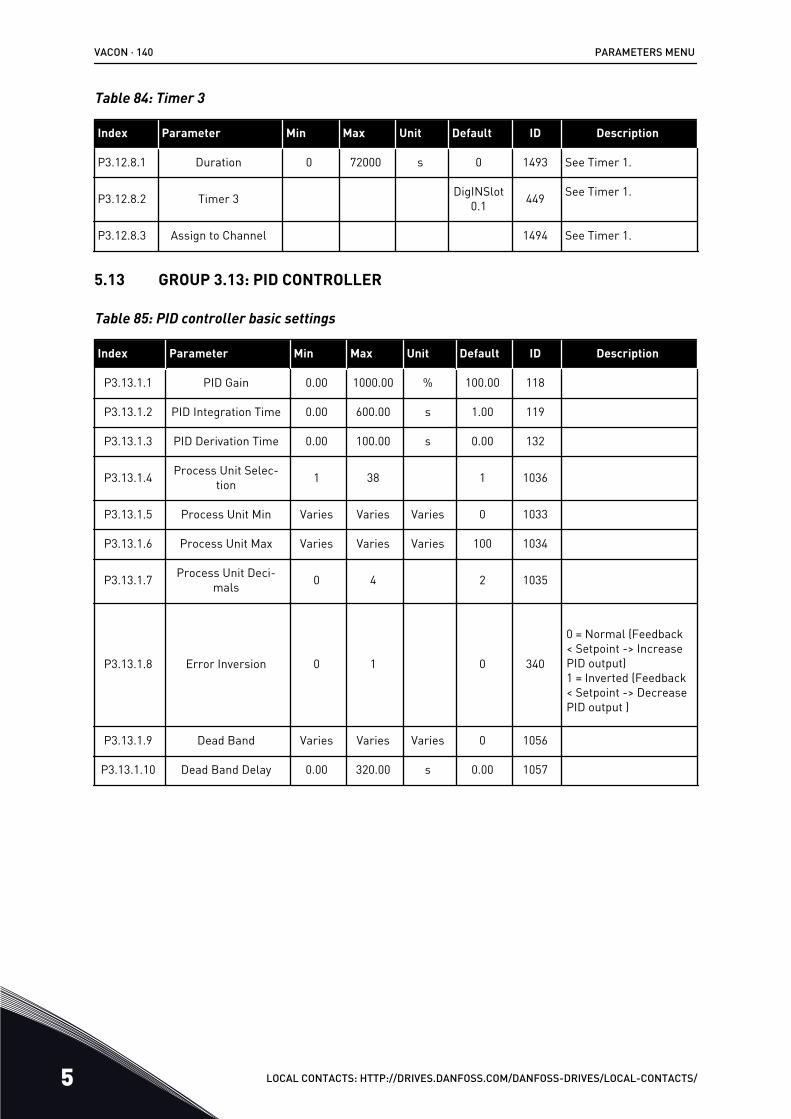
Table 84: Timer 3
Index Parameter Min Max Unit Default ID Description
P3.12.8.1 Duration 0 72000 s 0 1493 See Timer 1.
P3.12.8.2 Timer 3 DigINSlot0.1 449 See Timer 1.
P3.12.8.3 Assign to Channel 1494 See Timer 1.
5.13 GROUP 3.13: PID CONTROLLER
Table 85: PID controller basic settings
Index Parameter Min Max Unit Default ID Description
P3.13.1.1 PID Gain 0.00 1000.00 % 100.00 118
P3.13.1.2 PID Integration Time 0.00 600.00 s 1.00 119
P3.13.1.3 PID Derivation Time 0.00 100.00 s 0.00 132
P3.13.1.4 Process Unit Selec-tion 1 38 1 1036
P3.13.1.5 Process Unit Min Varies Varies Varies 0 1033
P3.13.1.6 Process Unit Max Varies Varies Varies 100 1034
P3.13.1.7 Process Unit Deci-mals 0 4 2 1035
P3.13.1.8 Error Inversion 0 1 0 340
0 = Normal (Feedback< Setpoint -> IncreasePID output)1 = Inverted (Feedback< Setpoint -> DecreasePID output )
P3.13.1.9 Dead Band Varies Varies Varies 0 1056
P3.13.1.10 Dead Band Delay 0.00 320.00 s 0.00 1057
VACON · 140 PARAMETERS MENU
5 LOCAL CONTACTS: HTTP://DRIVES.DANFOSS.COM/DANFOSS-DRIVES/LOCAL-CONTACTS/
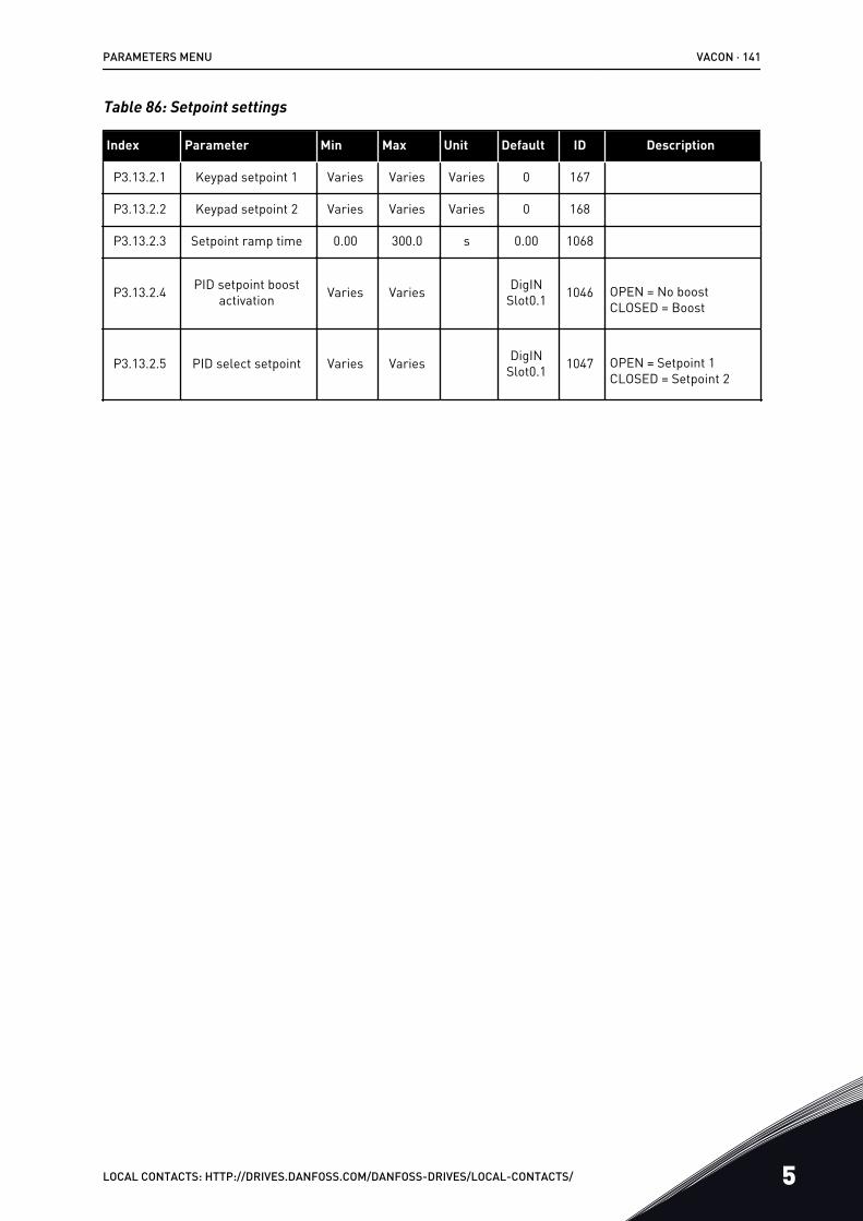
Table 86: Setpoint settings
Index Parameter Min Max Unit Default ID Description
P3.13.2.1 Keypad setpoint 1 Varies Varies Varies 0 167
P3.13.2.2 Keypad setpoint 2 Varies Varies Varies 0 168
P3.13.2.3 Setpoint ramp time 0.00 300.0 s 0.00 1068
P3.13.2.4 PID setpoint boostactivation Varies Varies DigIN
Slot0.1 1046 OPEN = No boostCLOSED = Boost
P3.13.2.5 PID select setpoint Varies Varies DigINSlot0.1 1047 OPEN = Setpoint 1
CLOSED = Setpoint 2
PARAMETERS MENU VACON · 141
LOCAL CONTACTS: HTTP://DRIVES.DANFOSS.COM/DANFOSS-DRIVES/LOCAL-CONTACTS/ 5
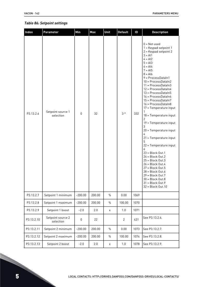
Table 86: Setpoint settings
Index Parameter Min Max Unit Default ID Description
P3.13.2.6 Setpoint source 1selection 0 32 3 * 332
0 = Not used1 = Keypad setpoint 12 = Keypad setpoint 23 = AI14 = AI25 = AI36 = AI47 = AI58 = AI69 = ProcessDataIn110 = ProcessDataIn211 = ProcessDataIn312 = ProcessDataIn413 = ProcessDataIn514 = ProcessDataIn615 = ProcessDataIn716 = ProcessDataIn817 = Temperature input118 = Temperature input219 = Temperature input320 = Temperature input421 = Temperature input522 = Temperature input623 = Block Out.124 = Block Out.225 = Block Out.326 = Block Out.427 = Block Out.528 = Block Out.629 = Block Out.730 = Block Out.831 = Block Out.932 = Block Out.10
P3.13.2.7 Setpoint 1 minimum -200.00 200.00 % 0.00 1069
P3.13.2.8 Setpoint 1 maximum -200.00 200.00 % 100.00 1070
P3.13.2.9 Setpoint 1 boost -2.0 2.0 x 1.0 1071
P3.13.2.10 Setpoint source 2selection 0 22 2 431 See P3.13.2.6.
P3.13.2.11 Setpoint 2 minimum -200.00 200.00 % 0.00 1073 See P3.13.2.7.
P3.13.2.12 Setpoint 2 maximum -200.00 200.00 % 100.00 1074 See P3.13.2.8.
P3.13.2.13 Setpoint 2 boost -2.0 2.0 x 1.0 1078 See P3.13.2.9.
VACON · 142 PARAMETERS MENU
5 LOCAL CONTACTS: HTTP://DRIVES.DANFOSS.COM/DANFOSS-DRIVES/LOCAL-CONTACTS/

* = The selection of the application with parameter P1.2 Application gives the default value.See the default values in Chapter 12 Appendix 1.
PARAMETERS MENU VACON · 143
LOCAL CONTACTS: HTTP://DRIVES.DANFOSS.COM/DANFOSS-DRIVES/LOCAL-CONTACTS/ 5
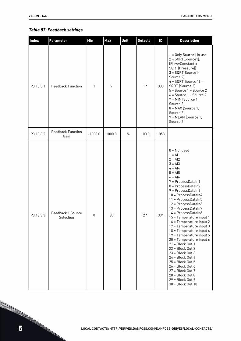
Table 87: Feedback settings
Index Parameter Min Max Unit Default ID Description
P3.13.3.1 Feedback Function 1 9 1 * 333
1 = Only Source1 in use2 = SQRT(Source1);(Flow=Constant xSQRT(Pressure))3 = SQRT(Source1-Source 2)4 = SQRT(Source 1) +SQRT (Source 2)5 = Source 1 + Source 26 = Source 1 - Source 27 = MIN (Source 1,Source 2)8 = MAX (Source 1,Source 2)9 = MEAN (Source 1,Source 2)
P3.13.3.2 Feedback FunctionGain -1000.0 1000.0 % 100.0 1058
P3.13.3.3 Feedback 1 SourceSelection 0 30 2 * 334
0 = Not used1 = AI12 = AI23 = AI34 = AI45 = AI56 = AI67 = ProcessDataIn18 = ProcessDataIn29 = ProcessDataIn310 = ProcessDataIn411 = ProcessDataIn512 = ProcessDataIn613 = ProcessDataIn714 = ProcessDataIn815 = Temperature input 116 = Temperature input 217 = Temperature input 318 = Temperature input 419 = Temperature input 520 = Temperature input 621 = Block Out.122 = Block Out.223 = Block Out.324 = Block Out.425 = Block Out.526 = Block Out.627 = Block Out.728 = Block Out.829 = Block Out.930 = Block Out.10
VACON · 144 PARAMETERS MENU
5 LOCAL CONTACTS: HTTP://DRIVES.DANFOSS.COM/DANFOSS-DRIVES/LOCAL-CONTACTS/
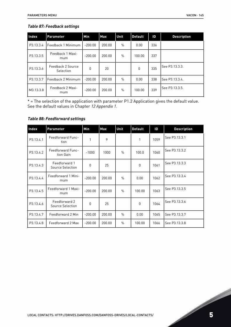
Table 87: Feedback settings
Index Parameter Min Max Unit Default ID Description
P3.13.3.4 Feedback 1 Minimum -200.00 200.00 % 0.00 336
P3.13.3.5 Feedback 1 Maxi-mum -200.00 200.00 % 100.00 337
P3.13.3.6 Feedback 2 SourceSelection 0 20 0 335 See P3.13.3.3.
P3.13.3.7 Feedback 2 Minimum -200.00 200.00 % 0.00 338 See P3.13.3.4.
M3.13.3.8 Feedback 2 Maxi-mum -200.00 200.00 % 100.00 339 See P3.13.3.5.
* = The selection of the application with parameter P1.2 Application gives the default value.See the default values in Chapter 12 Appendix 1.
Table 88: Feedforward settings
Index Parameter Min Max Unit Default ID Description
P3.13.4.1 Feedforward Func-tion 1 9 1 1059 See P3.13.3.1
P3.13.4.2 Feedforward Func-tion Gain -1000 1000 % 100.0 1060 See P3.13.3.2
P3.13.4.3 Feedforward 1Source Selection 0 25 0 1061 See P3.13.3.3
P3.13.4.4 Feedforward 1 Mini-mum -200.00 200.00 % 0.00 1062 See P3.13.3.4
P3.13.4.5 Feedforward 1 Maxi-mum -200.00 200.00 % 100.00 1063 See P3.13.3.5
P3.13.4.6 Feedforward 2Source Selection 0 25 0 1064 See P3.13.3.6
P3.13.4.7 Feedforward 2 Min -200.00 200.00 % 0.00 1065 See P3.13.3.7
P3.13.4.8 Feedforward 2 Max -200.00 200.00 % 100.00 1066 See P3.13.3.8
PARAMETERS MENU VACON · 145
LOCAL CONTACTS: HTTP://DRIVES.DANFOSS.COM/DANFOSS-DRIVES/LOCAL-CONTACTS/ 5
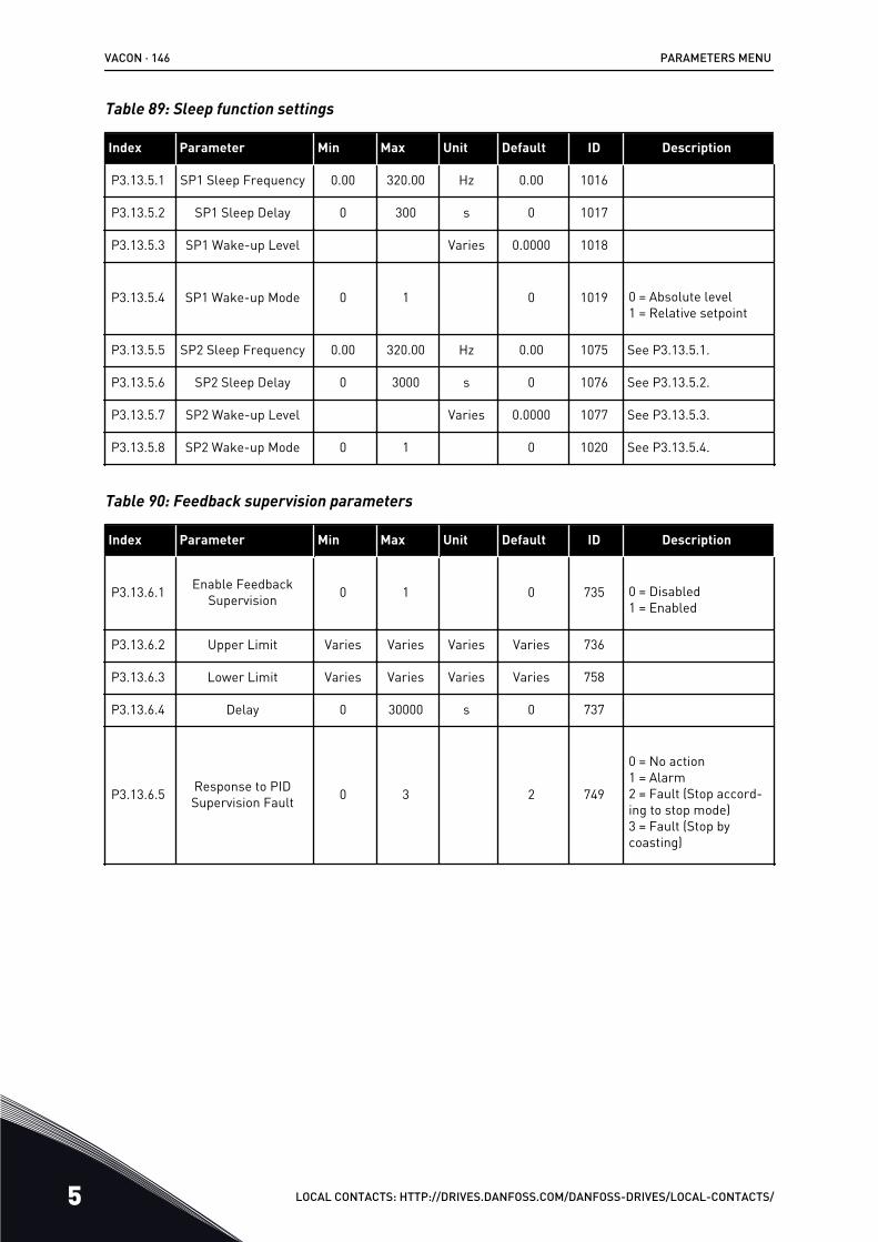
Table 89: Sleep function settings
Index Parameter Min Max Unit Default ID Description
P3.13.5.1 SP1 Sleep Frequency 0.00 320.00 Hz 0.00 1016
P3.13.5.2 SP1 Sleep Delay 0 300 s 0 1017
P3.13.5.3 SP1 Wake-up Level Varies 0.0000 1018
P3.13.5.4 SP1 Wake-up Mode 0 1 0 1019 0 = Absolute level1 = Relative setpoint
P3.13.5.5 SP2 Sleep Frequency 0.00 320.00 Hz 0.00 1075 See P3.13.5.1.
P3.13.5.6 SP2 Sleep Delay 0 3000 s 0 1076 See P3.13.5.2.
P3.13.5.7 SP2 Wake-up Level Varies 0.0000 1077 See P3.13.5.3.
P3.13.5.8 SP2 Wake-up Mode 0 1 0 1020 See P3.13.5.4.
Table 90: Feedback supervision parameters
Index Parameter Min Max Unit Default ID Description
P3.13.6.1 Enable FeedbackSupervision 0 1 0 735 0 = Disabled
1 = Enabled
P3.13.6.2 Upper Limit Varies Varies Varies Varies 736
P3.13.6.3 Lower Limit Varies Varies Varies Varies 758
P3.13.6.4 Delay 0 30000 s 0 737
P3.13.6.5 Response to PIDSupervision Fault 0 3 2 749
0 = No action1 = Alarm2 = Fault (Stop accord-ing to stop mode)3 = Fault (Stop bycoasting)
VACON · 146 PARAMETERS MENU
5 LOCAL CONTACTS: HTTP://DRIVES.DANFOSS.COM/DANFOSS-DRIVES/LOCAL-CONTACTS/
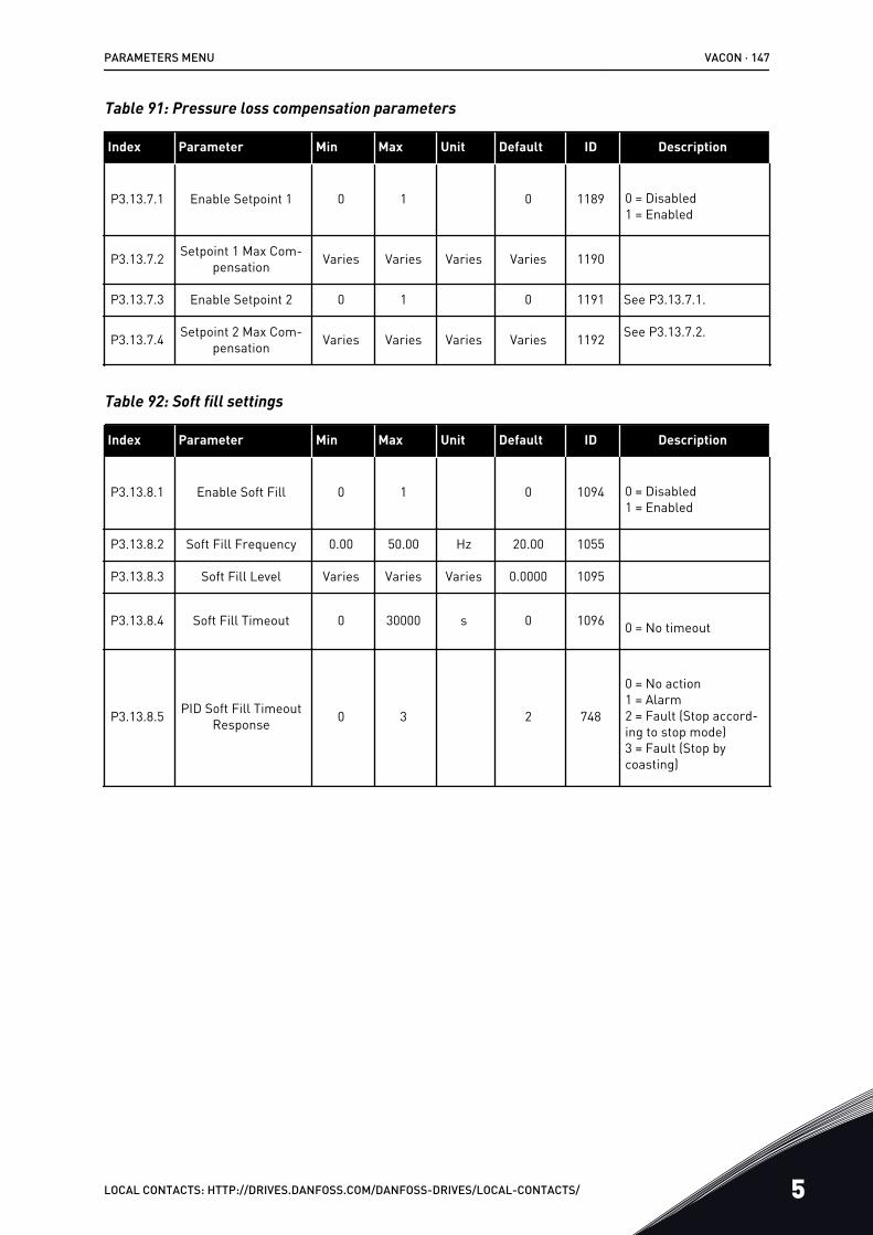
Table 91: Pressure loss compensation parameters
Index Parameter Min Max Unit Default ID Description
P3.13.7.1 Enable Setpoint 1 0 1 0 1189 0 = Disabled1 = Enabled
P3.13.7.2 Setpoint 1 Max Com-pensation Varies Varies Varies Varies 1190
P3.13.7.3 Enable Setpoint 2 0 1 0 1191 See P3.13.7.1.
P3.13.7.4 Setpoint 2 Max Com-pensation Varies Varies Varies Varies 1192 See P3.13.7.2.
Table 92: Soft fill settings
Index Parameter Min Max Unit Default ID Description
P3.13.8.1 Enable Soft Fill 0 1 0 1094 0 = Disabled1 = Enabled
P3.13.8.2 Soft Fill Frequency 0.00 50.00 Hz 20.00 1055
P3.13.8.3 Soft Fill Level Varies Varies Varies 0.0000 1095
P3.13.8.4 Soft Fill Timeout 0 30000 s 0 1096 0 = No timeout
P3.13.8.5 PID Soft Fill TimeoutResponse 0 3 2 748
0 = No action1 = Alarm2 = Fault (Stop accord-ing to stop mode)3 = Fault (Stop bycoasting)
PARAMETERS MENU VACON · 147
LOCAL CONTACTS: HTTP://DRIVES.DANFOSS.COM/DANFOSS-DRIVES/LOCAL-CONTACTS/ 5
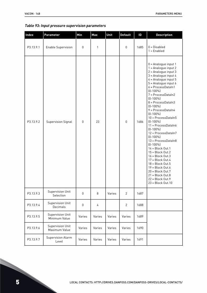
Table 93: Input pressure supervision parameters
Index Parameter Min Max Unit Default ID Description
P3.13.9.1 Enable Supervision 0 1 0 1685 0 = Disabled1 = Enabled
P3.13.9.2 Supervision Signal 0 23 0 1686
0 = Analogue input 11 = Analogue input 22 = Analogue input 33 = Analogue input 44 = Analogue input 55 = Analogue input 66 = ProcessDataIn1(0-100%)7 = ProcessDataIn2(0-100%)8 = ProcessDataIn3(0-100%)9 = ProcessDataIn4(0-100%)10 = ProcessDataIn5(0-100%)11 = ProcessDataIn6(0-100%)12 = ProcessDataIn7(0-100%)13 = ProcessDataIn8(0-100%)14 = Block Out.115 = Block Out.216 = Block Out.317 = Block Out.418 = Block Out.519 = Block Out.620 = Block Out.721 = Block Out.822 = Block Out.923 = Block Out.10
P3.13.9.3 Supervision UnitSelection 0 8 Varies 2 1687
P3.13.9.4 Supervision UnitDecimals 0 4 2 1688
P3.13.9.5 Supervision UnitMinimum Value Varies Varies Varies Varies 1689
P3.13.9.6 Supervision UnitMaximum Value Varies Varies Varies Varies 1690
P3.13.9.7 Supervision AlarmLevel Varies Varies Varies Varies 1691
VACON · 148 PARAMETERS MENU
5 LOCAL CONTACTS: HTTP://DRIVES.DANFOSS.COM/DANFOSS-DRIVES/LOCAL-CONTACTS/

Table 93: Input pressure supervision parameters
Index Parameter Min Max Unit Default ID Description
P3.13.9.8 Supervision FaultLevel Varies Varies Varies Varies 1692
P3.13.9.9 Supervision FaultDelay 0.00 60.00 s 5.00 1693
P3.13.9.10 PID Setpoint Reduc-tion 0.0 100.0 % 10.0 1694
V3.13.9.11 Input Pressure Varies Varies Varies Varies 1695
This monitoring valueshows the actual valueof the pump inputpressure.
PARAMETERS MENU VACON · 149
LOCAL CONTACTS: HTTP://DRIVES.DANFOSS.COM/DANFOSS-DRIVES/LOCAL-CONTACTS/ 5
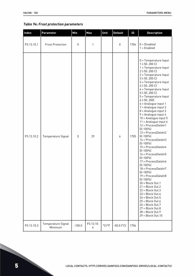
Table 94: Frost protection parameters
Index Parameter Min Max Unit Default ID Description
P3.13.10.1 Frost Protection 0 1 0 1704 0 = Disabled1 = Enabled
P3.13.10.2 Temperature Signal 0 29 6 1705
0 = Temperature Input1 (-50..200 C)1 = Temperature Input2 (-50..200 C)2 = Temperature Input3 (-50..200 C)3 = Temperature Input4 (-50..200 C)4 = Temperature Input5 (-50..200 C)5 = Temperature Input6 (-50..200)6 = Analogue input 17 = Analogue input 28 = Analogue input 39 = Analogue input 410 = Analogue input 511 = Analogue input 612 = ProcessDataIn1(0-100%)13 = ProcessDataIn2(0-100%)14 = ProcessDataIn3(0-100%)15 = ProcessDataIn4(0-100%)16 = ProcessDataIn5(0-100%)17 = ProcessDataIn6(0-100%)18 = ProcessDataIn7(0-100%)19 = ProcessDataIn8(0-100%)20 = Block Out.121 = Block Out.222 = Block Out.323 = Block Out.424 = Block Out.525 = Block Out.626 = Block Out.727 = Block Out.828 = Block Out.929 = Block Out.10
P3.13.10.3 Temperature SignalMinimum -100.0 P3.13.10.
4 °C/°F -50.0 (°C) 1706
VACON · 150 PARAMETERS MENU
5 LOCAL CONTACTS: HTTP://DRIVES.DANFOSS.COM/DANFOSS-DRIVES/LOCAL-CONTACTS/
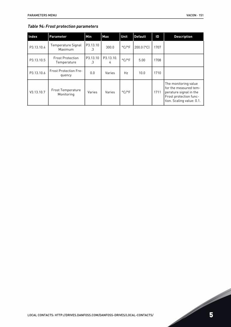
Table 94: Frost protection parameters
Index Parameter Min Max Unit Default ID Description
P3.13.10.4 Temperature SignalMaximum
P3.13.10.3 300.0 °C/°F 200.0 (°C) 1707
P3.13.10.5 Frost ProtectionTemperature
P3.13.10.3
P3.13.10.4 °C/°F 5.00 1708
P3.13.10.6 Frost Protection Fre-quency 0.0 Varies Hz 10.0 1710
V3.13.10.7 Frost TemperatureMonitoring Varies Varies °C/°F 1711
The monitoring valuefor the measured tem-perature signal in theFrost protection func-tion. Scaling value: 0.1.
PARAMETERS MENU VACON · 151
LOCAL CONTACTS: HTTP://DRIVES.DANFOSS.COM/DANFOSS-DRIVES/LOCAL-CONTACTS/ 5

5.14 GROUP 3.14: EXTERNAL PID CONTROLLER
Table 95: Basic settings for the external PID controller
Index Parameter Min Max Unit Default ID Description
P3.14.1.1 Enable External PID 0 1 0 1630 0 = Disabled1 = Enabled
P3.14.1.2 Start Signal DigINSlot0.2 1049
OPEN = PID2 in stopmodeCLOSED = PID2 regu-lating
P3.14.1.3 Output in Stop 0.0 100.0 % 0.0 1100
P3.14.1.4 PID Gain 0.00 1000.00 % 100.00 1631 See P3.13.1.1
P3.14.1.5 PID Integration Time 0.00 600.00 s 1.00 1632 See P3.13.1.2
P3.14.1.6 PID Derivation Time 0.00 100.00 s 0.00 1633 See P3.13.1.3
P3.14.1.7 Process Unit Selec-tion 0 37 0 1635 See P3.13.1.4
P3.14.1.8 Process Unit Min Varies Varies Varies 0 1664 See P3.13.1.5
P3.14.1.9 Process Unit Max Varies Varies Varies 100 1665 See P3.13.1.6
P3.14.1.10 Process Unit Deci-mals 0 4 2 1666 See P3.13.1.7
P3.14.1.11 Error Inversion 0 1 0 1636 See P3.13.1.8
P3.14.1.12 Dead Band Varies Varies Varies 0.0 1637 See P3.13.1.9
P3.14.1.13 Dead Band Delay 0.00 320.00 s 0.00 1638 See P3.13.1.10
VACON · 152 PARAMETERS MENU
5 LOCAL CONTACTS: HTTP://DRIVES.DANFOSS.COM/DANFOSS-DRIVES/LOCAL-CONTACTS/
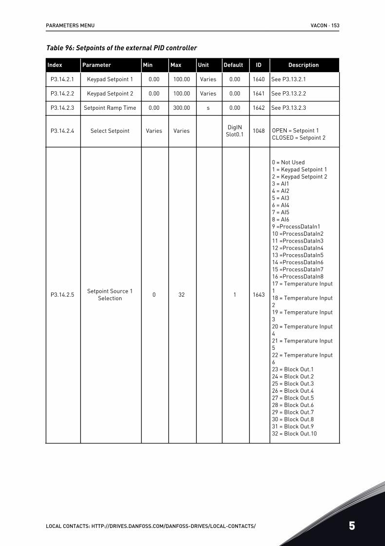
Table 96: Setpoints of the external PID controller
Index Parameter Min Max Unit Default ID Description
P3.14.2.1 Keypad Setpoint 1 0.00 100.00 Varies 0.00 1640 See P3.13.2.1
P3.14.2.2 Keypad Setpoint 2 0.00 100.00 Varies 0.00 1641 See P3.13.2.2
P3.14.2.3 Setpoint Ramp Time 0.00 300.00 s 0.00 1642 See P3.13.2.3
P3.14.2.4 Select Setpoint Varies Varies DigINSlot0.1 1048 OPEN = Setpoint 1
CLOSED = Setpoint 2
P3.14.2.5 Setpoint Source 1Selection 0 32 1 1643
0 = Not Used1 = Keypad Setpoint 12 = Keypad Setpoint 23 = AI14 = AI25 = AI36 = AI47 = AI58 = AI69 =ProcessDataIn110 =ProcessDataIn211 =ProcessDataIn312 =ProcessDataIn413 =ProcessDataIn514 =ProcessDataIn615 =ProcessDataIn716 =ProcessDataIn817 = Temperature Input118 = Temperature Input219 = Temperature Input320 = Temperature Input421 = Temperature Input522 = Temperature Input623 = Block Out.124 = Block Out.225 = Block Out.326 = Block Out.427 = Block Out.528 = Block Out.629 = Block Out.730 = Block Out.831 = Block Out.932 = Block Out.10
PARAMETERS MENU VACON · 153
LOCAL CONTACTS: HTTP://DRIVES.DANFOSS.COM/DANFOSS-DRIVES/LOCAL-CONTACTS/ 5
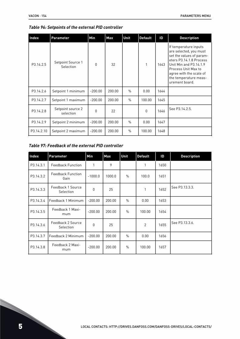
Table 96: Setpoints of the external PID controller
Index Parameter Min Max Unit Default ID Description
P3.14.2.5 Setpoint Source 1Selection 0 32 1 1643
If temperature inputsare selected, you mustset the values of param-eters P3.14.1.8 ProcessUnit Min and P3.14.1.9Process Unit Max toagree with the scale ofthe temperature meas-urement board.
P3.14.2.6 Setpoint 1 minimum -200.00 200.00 % 0.00 1644
P3.14.2.7 Setpoint 1 maximum -200.00 200.00 % 100.00 1645
P3.14.2.8 Setpoint source 2selection 0 22 0 1646 See P3.14.2.5.
P3.14.2.9 Setpoint 2 minimum -200.00 200.00 % 0.00 1647
P3.14.2.10 Setpoint 2 maximum -200.00 200.00 % 100.00 1648
Table 97: Feedback of the external PID controller
Index Parameter Min Max Unit Default ID Description
P3.14.3.1 Feedback Function 1 9 1 1650
P3.14.3.2 Feedback FunctionGain -1000.0 1000.0 % 100.0 1651
P3.14.3.3 Feedback 1 SourceSelection 0 25 1 1652 See P3.13.3.3.
P3.14.3.4 Feedback 1 Minimum -200.00 200.00 % 0.00 1653
P3.14.3.5 Feedback 1 Maxi-mum -200.00 200.00 % 100.00 1654
P3.14.3.6 Feedback 2 SourceSelection 0 25 2 1655 See P3.13.3.6.
P3.14.3.7 Feedback 2 Minimum -200.00 200.00 % 0.00 1656
P3.14.3.8 Feedback 2 Maxi-mum -200.00 200.00 % 100.00 1657
VACON · 154 PARAMETERS MENU
5 LOCAL CONTACTS: HTTP://DRIVES.DANFOSS.COM/DANFOSS-DRIVES/LOCAL-CONTACTS/
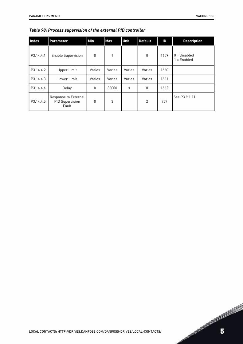
Table 98: Process supervision of the external PID controller
Index Parameter Min Max Unit Default ID Description
P3.14.4.1 Enable Supervision 0 1 0 1659 0 = Disabled1 = Enabled
P3.14.4.2 Upper Limit Varies Varies Varies Varies 1660
P3.14.4.3 Lower Limit Varies Varies Varies Varies 1661
P3.14.4.4 Delay 0 30000 s 0 1662
P3.14.4.5Response to External
PID SupervisionFault
0 3 2 757See P3.9.1.11.
PARAMETERS MENU VACON · 155
LOCAL CONTACTS: HTTP://DRIVES.DANFOSS.COM/DANFOSS-DRIVES/LOCAL-CONTACTS/ 5
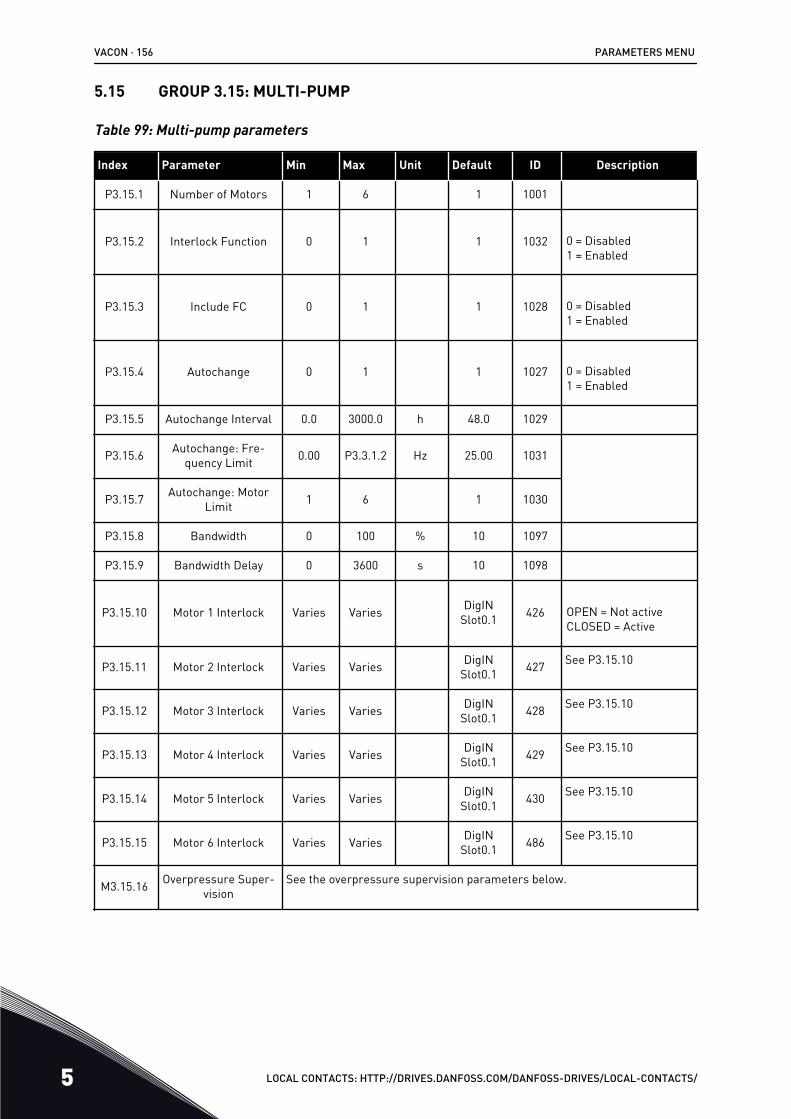
5.15 GROUP 3.15: MULTI-PUMP
Table 99: Multi-pump parameters
Index Parameter Min Max Unit Default ID Description
P3.15.1 Number of Motors 1 6 1 1001
P3.15.2 Interlock Function 0 1 1 1032 0 = Disabled1 = Enabled
P3.15.3 Include FC 0 1 1 1028 0 = Disabled1 = Enabled
P3.15.4 Autochange 0 1 1 1027 0 = Disabled1 = Enabled
P3.15.5 Autochange Interval 0.0 3000.0 h 48.0 1029
P3.15.6 Autochange: Fre-quency Limit 0.00 P3.3.1.2 Hz 25.00 1031
P3.15.7 Autochange: MotorLimit 1 6 1 1030
P3.15.8 Bandwidth 0 100 % 10 1097
P3.15.9 Bandwidth Delay 0 3600 s 10 1098
P3.15.10 Motor 1 Interlock Varies Varies DigINSlot0.1 426 OPEN = Not active
CLOSED = Active
P3.15.11 Motor 2 Interlock Varies Varies DigINSlot0.1 427 See P3.15.10
P3.15.12 Motor 3 Interlock Varies Varies DigINSlot0.1 428 See P3.15.10
P3.15.13 Motor 4 Interlock Varies Varies DigINSlot0.1 429 See P3.15.10
P3.15.14 Motor 5 Interlock Varies Varies DigINSlot0.1 430 See P3.15.10
P3.15.15 Motor 6 Interlock Varies Varies DigINSlot0.1 486 See P3.15.10
M3.15.16 Overpressure Super-vision
See the overpressure supervision parameters below.
VACON · 156 PARAMETERS MENU
5 LOCAL CONTACTS: HTTP://DRIVES.DANFOSS.COM/DANFOSS-DRIVES/LOCAL-CONTACTS/
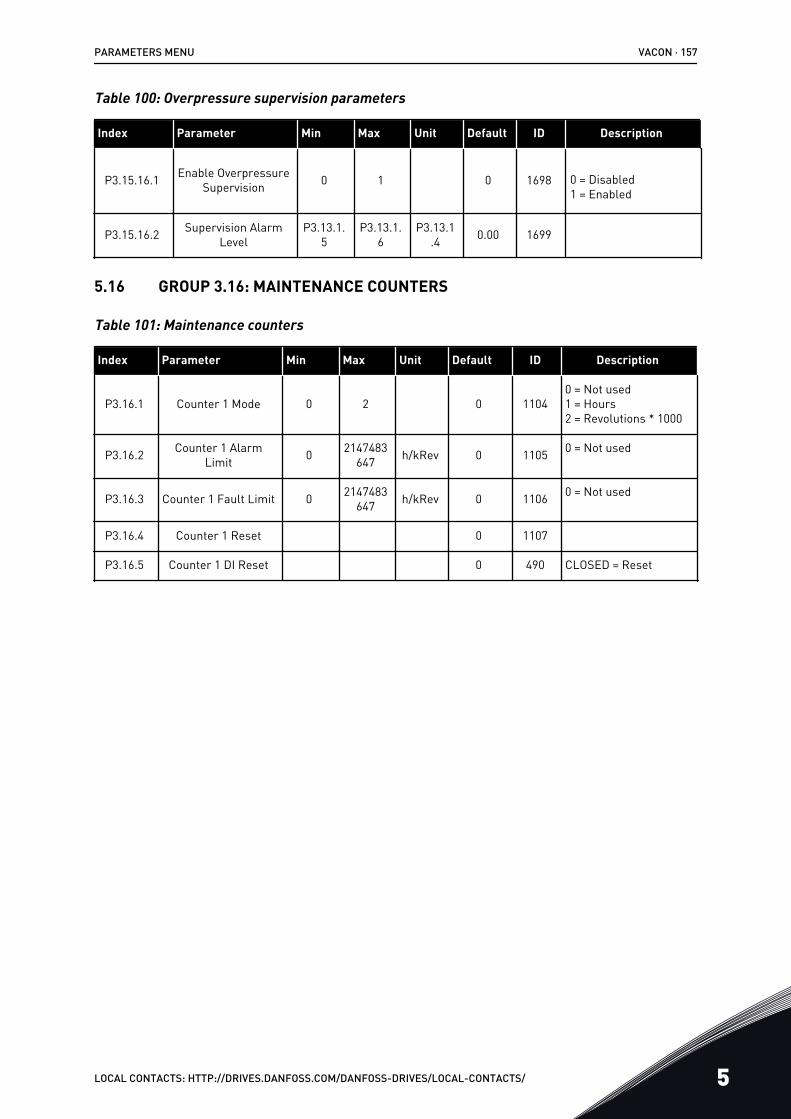
Table 100: Overpressure supervision parameters
Index Parameter Min Max Unit Default ID Description
P3.15.16.1 Enable OverpressureSupervision 0 1 0 1698 0 = Disabled
1 = Enabled
P3.15.16.2 Supervision AlarmLevel
P3.13.1.5
P3.13.1.6
P3.13.1.4 0.00 1699
5.16 GROUP 3.16: MAINTENANCE COUNTERS
Table 101: Maintenance counters
Index Parameter Min Max Unit Default ID Description
P3.16.1 Counter 1 Mode 0 2 0 11040 = Not used1 = Hours2 = Revolutions * 1000
P3.16.2 Counter 1 AlarmLimit 0 2147483
647 h/kRev 0 1105 0 = Not used
P3.16.3 Counter 1 Fault Limit 0 2147483647 h/kRev 0 1106 0 = Not used
P3.16.4 Counter 1 Reset 0 1107
P3.16.5 Counter 1 DI Reset 0 490 CLOSED = Reset
PARAMETERS MENU VACON · 157
LOCAL CONTACTS: HTTP://DRIVES.DANFOSS.COM/DANFOSS-DRIVES/LOCAL-CONTACTS/ 5
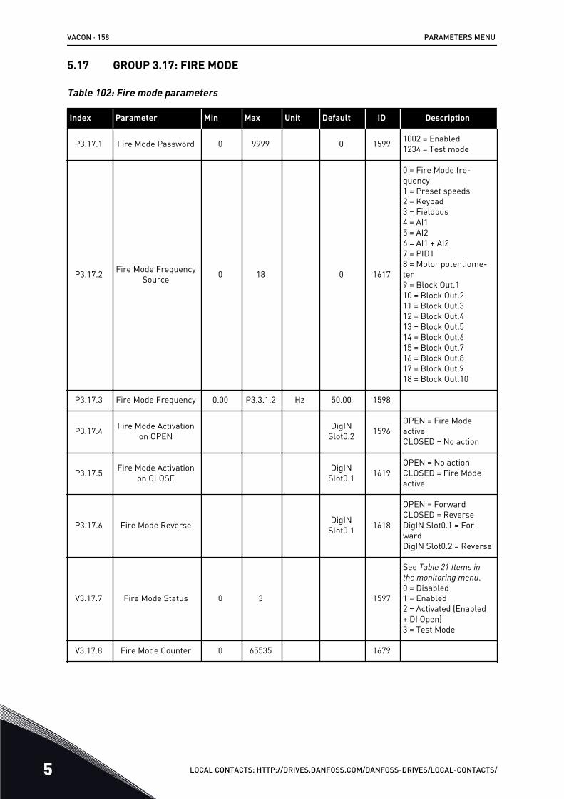
5.17 GROUP 3.17: FIRE MODE
Table 102: Fire mode parameters
Index Parameter Min Max Unit Default ID Description
P3.17.1 Fire Mode Password 0 9999 0 1599 1002 = Enabled1234 = Test mode
P3.17.2 Fire Mode FrequencySource 0 18 0 1617
0 = Fire Mode fre-quency1 = Preset speeds2 = Keypad3 = Fieldbus4 = AI15 = AI26 = AI1 + AI27 = PID18 = Motor potentiome-ter9 = Block Out.110 = Block Out.211 = Block Out.312 = Block Out.413 = Block Out.514 = Block Out.615 = Block Out.716 = Block Out.817 = Block Out.918 = Block Out.10
P3.17.3 Fire Mode Frequency 0.00 P3.3.1.2 Hz 50.00 1598
P3.17.4 Fire Mode Activationon OPEN
DigINSlot0.2 1596
OPEN = Fire ModeactiveCLOSED = No action
P3.17.5 Fire Mode Activationon CLOSE
DigINSlot0.1 1619
OPEN = No actionCLOSED = Fire Modeactive
P3.17.6 Fire Mode Reverse DigINSlot0.1 1618
OPEN = ForwardCLOSED = ReverseDigIN Slot0.1 = For-wardDigIN Slot0.2 = Reverse
V3.17.7 Fire Mode Status 0 3 1597
See Table 21 Items in the monitoring menu.0 = Disabled1 = Enabled2 = Activated (Enabled+ DI Open)3 = Test Mode
V3.17.8 Fire Mode Counter 0 65535 1679
VACON · 158 PARAMETERS MENU
5 LOCAL CONTACTS: HTTP://DRIVES.DANFOSS.COM/DANFOSS-DRIVES/LOCAL-CONTACTS/
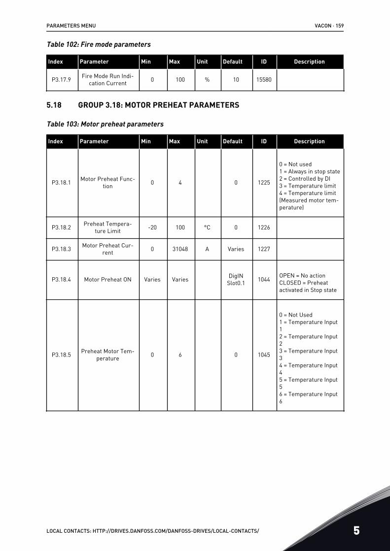
Table 102: Fire mode parameters
Index Parameter Min Max Unit Default ID Description
P3.17.9 Fire Mode Run Indi-cation Current 0 100 % 10 15580
5.18 GROUP 3.18: MOTOR PREHEAT PARAMETERS
Table 103: Motor preheat parameters
Index Parameter Min Max Unit Default ID Description
P3.18.1 Motor Preheat Func-tion 0 4 0 1225
0 = Not used1 = Always in stop state2 = Controlled by DI3 = Temperature limit4 = Temperature limit(Measured motor tem-perature)
P3.18.2 Preheat Tempera-ture Limit -20 100 °C 0 1226
P3.18.3 Motor Preheat Cur-rent 0 31048 A Varies 1227
P3.18.4 Motor Preheat ON Varies Varies DigINSlot0.1 1044 OPEN = No action
CLOSED = Preheatactivated in Stop state
P3.18.5 Preheat Motor Tem-perature 0 6 0 1045
0 = Not Used1 = Temperature Input12 = Temperature Input23 = Temperature Input34 = Temperature Input45 = Temperature Input56 = Temperature Input6
PARAMETERS MENU VACON · 159
LOCAL CONTACTS: HTTP://DRIVES.DANFOSS.COM/DANFOSS-DRIVES/LOCAL-CONTACTS/ 5
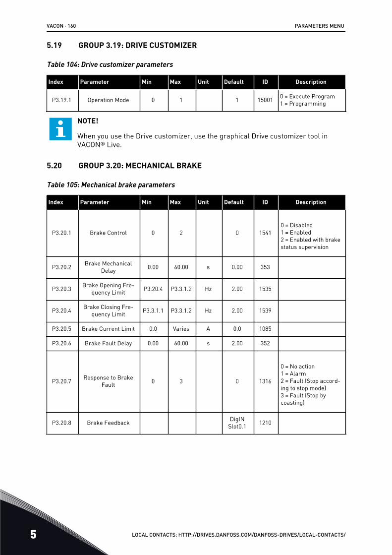
5.19 GROUP 3.19: DRIVE CUSTOMIZER
Table 104: Drive customizer parameters
Index Parameter Min Max Unit Default ID Description
P3.19.1 Operation Mode 0 1 1 15001 0 = Execute Program1 = Programming
NOTE!
When you use the Drive customizer, use the graphical Drive customizer tool inVACON® Live.
5.20 GROUP 3.20: MECHANICAL BRAKE
Table 105: Mechanical brake parameters
Index Parameter Min Max Unit Default ID Description
P3.20.1 Brake Control 0 2 0 15410 = Disabled1 = Enabled2 = Enabled with brakestatus supervision
P3.20.2 Brake MechanicalDelay 0.00 60.00 s 0.00 353
P3.20.3 Brake Opening Fre-quency Limit P3.20.4 P3.3.1.2 Hz 2.00 1535
P3.20.4 Brake Closing Fre-quency Limit P3.3.1.1 P3.3.1.2 Hz 2.00 1539
P3.20.5 Brake Current Limit 0.0 Varies A 0.0 1085
P3.20.6 Brake Fault Delay 0.00 60.00 s 2.00 352
P3.20.7 Response to BrakeFault 0 3 0 1316
0 = No action1 = Alarm2 = Fault (Stop accord-ing to stop mode)3 = Fault (Stop bycoasting)
P3.20.8 Brake Feedback DigINSlot0.1 1210
VACON · 160 PARAMETERS MENU
5 LOCAL CONTACTS: HTTP://DRIVES.DANFOSS.COM/DANFOSS-DRIVES/LOCAL-CONTACTS/
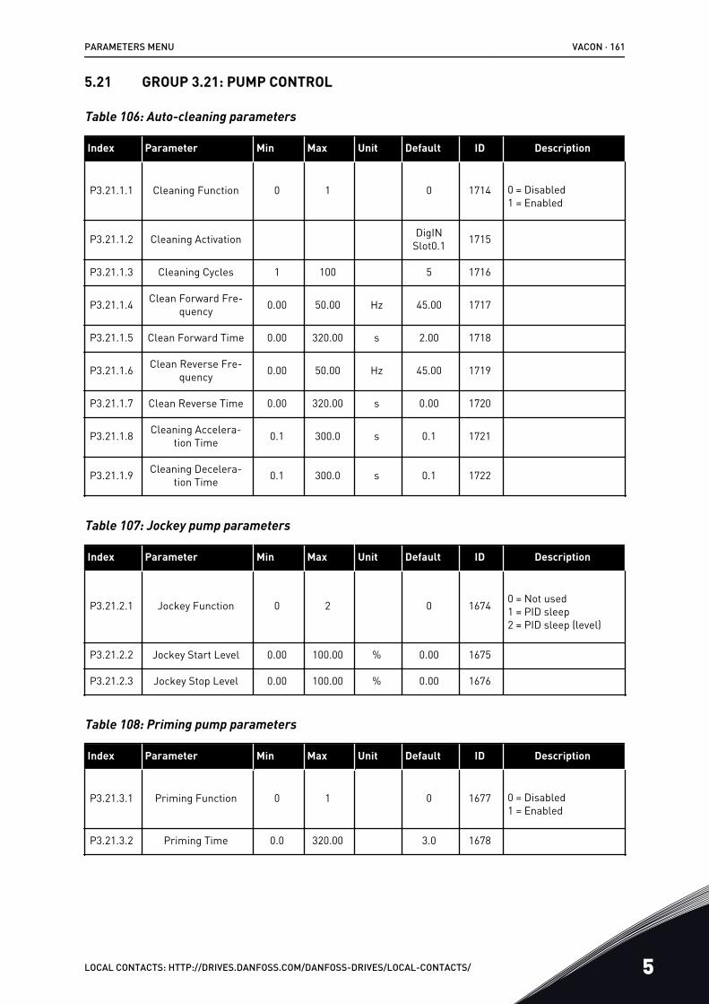
5.21 GROUP 3.21: PUMP CONTROL
Table 106: Auto-cleaning parameters
Index Parameter Min Max Unit Default ID Description
P3.21.1.1 Cleaning Function 0 1 0 1714 0 = Disabled1 = Enabled
P3.21.1.2 Cleaning Activation DigINSlot0.1 1715
P3.21.1.3 Cleaning Cycles 1 100 5 1716
P3.21.1.4 Clean Forward Fre-quency 0.00 50.00 Hz 45.00 1717
P3.21.1.5 Clean Forward Time 0.00 320.00 s 2.00 1718
P3.21.1.6 Clean Reverse Fre-quency 0.00 50.00 Hz 45.00 1719
P3.21.1.7 Clean Reverse Time 0.00 320.00 s 0.00 1720
P3.21.1.8 Cleaning Accelera-tion Time 0.1 300.0 s 0.1 1721
P3.21.1.9 Cleaning Decelera-tion Time 0.1 300.0 s 0.1 1722
Table 107: Jockey pump parameters
Index Parameter Min Max Unit Default ID Description
P3.21.2.1 Jockey Function 0 2 0 1674 0 = Not used1 = PID sleep2 = PID sleep (level)
P3.21.2.2 Jockey Start Level 0.00 100.00 % 0.00 1675
P3.21.2.3 Jockey Stop Level 0.00 100.00 % 0.00 1676
Table 108: Priming pump parameters
Index Parameter Min Max Unit Default ID Description
P3.21.3.1 Priming Function 0 1 0 1677 0 = Disabled1 = Enabled
P3.21.3.2 Priming Time 0.0 320.00 3.0 1678
PARAMETERS MENU VACON · 161
LOCAL CONTACTS: HTTP://DRIVES.DANFOSS.COM/DANFOSS-DRIVES/LOCAL-CONTACTS/ 5
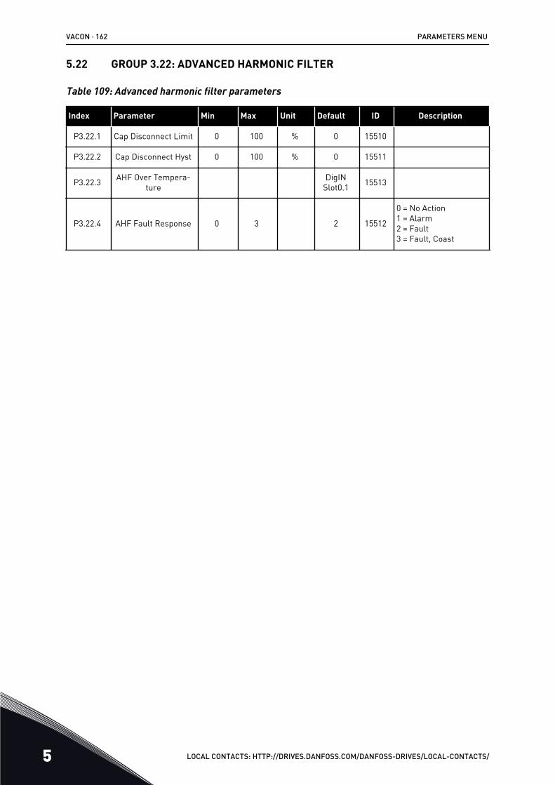
5.22 GROUP 3.22: ADVANCED HARMONIC FILTER
Table 109: Advanced harmonic filter parameters
Index Parameter Min Max Unit Default ID Description
P3.22.1 Cap Disconnect Limit 0 100 % 0 15510
P3.22.2 Cap Disconnect Hyst 0 100 % 0 15511
P3.22.3 AHF Over Tempera-ture
DigINSlot0.1 15513
P3.22.4 AHF Fault Response 0 3 2 15512
0 = No Action1 = Alarm2 = Fault3 = Fault, Coast
VACON · 162 PARAMETERS MENU
5 LOCAL CONTACTS: HTTP://DRIVES.DANFOSS.COM/DANFOSS-DRIVES/LOCAL-CONTACTS/
6 DIAGNOSTICS MENU6.1 ACTIVE FAULTS
When there is a fault or many faults, the display shows the name of the fault and blinks. PushOK to go back to the Diagnostics menu. The submenu Active faults shows the number offaults. To see the fault-time data, make a selection of a fault and push OK.
The fault stays active until you reset it. There are 5 ways to reset a fault.
• Push the Reset button for 2 s.• Go into the submenu Reset faults and use the parameter Reset Faults.• Give a reset signal in the I/O terminal.• Give a reset signal with the fieldbus.• Give a reset signal in VACON® Live.
The Active faults submenu can keep a storage of maximum 10 faults. The submenu showsthe faults in the sequence in which they occurred.
6.2 RESET FAULTS
In this menu, you can reset faults. See instructions in Chapter 11.1 A fault comes into view.
CAUTION!
Before you reset the fault, remove the external Control signal to prevent that yourestart the drive accidentally.
6.3 FAULT HISTORY
You can see 40 faults in the Fault history.
To see the details of a fault, go into Fault history, find the fault and push OK.
6.4 TOTAL COUNTERS
If you read a counter value through fieldbus, see Chapter 11.4 Total and trip counters.
DIAGNOSTICS MENU VACON · 163
LOCAL CONTACTS: HTTP://DRIVES.DANFOSS.COM/DANFOSS-DRIVES/LOCAL-CONTACTS/ 6
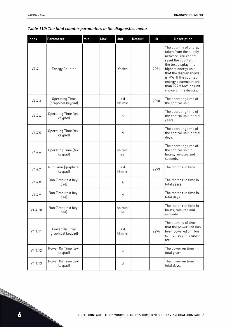
Table 110: The total counter parameters in the diagnostics menu
Index Parameter Min Max Unit Default ID Description
V4.4.1 Energy Counter Varies 2291
The quantity of energytaken from the supplynetwork. You cannotreset the counter. Inthe text display: thehighest energy unitthat the display showsis MW. If the countedenergy becomes morethan 999.9 MW, no unitshows on the display.
V4.4.3 Operating Time(graphical keypad)
a dhh:min 2298 The operating time of
the control unit.
V4.4.4 Operating Time (textkeypad) a
The operating time ofthe control unit in totalyears.
V4.4.5 Operating Time (textkeypad) d
The operating time ofthe control unit in totaldays.
V4.4.6 Operating Time (textkeypad)
hh:min:ss
The operating time ofthe control unit inhours, minutes andseconds.
V4.4.7 Run Time (graphicalkeypad)
a dhh:min 2293 The motor run time.
V4.4.8 Run Time (text key-pad) a The motor run time in
total years.
V4.4.9 Run Time (text key-pad) d The motor run time in
total days.
V4.4.10 Run Time (text key-pad)
hh:min:ss
The motor run time inhours, minutes andseconds.
V4.4.11 Power On Time(graphical keypad)
a dhh:min 2294
The quantity of timethat the power unit hasbeen powered on. Youcannot reset the coun-ter.
V4.4.12 Power On Time (textkeypad) a The power on time in
total years.
V4.4.13 Power On Time (textkeypad) d The power on time in
total days.
VACON · 164 DIAGNOSTICS MENU
6 LOCAL CONTACTS: HTTP://DRIVES.DANFOSS.COM/DANFOSS-DRIVES/LOCAL-CONTACTS/
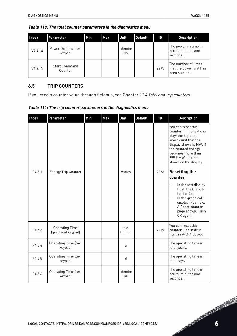
Table 110: The total counter parameters in the diagnostics menu
Index Parameter Min Max Unit Default ID Description
V4.4.14 Power On Time (textkeypad)
hh:min:ss
The power on time inhours, minutes andseconds.
V4.4.15 Start CommandCounter 2295
The number of timesthat the power unit hasbeen started.
6.5 TRIP COUNTERS
If you read a counter value through fieldbus, see Chapter 11.4 Total and trip counters.
Table 111: The trip counter parameters in the diagnostics menu
Index Parameter Min Max Unit Default ID Description
P4.5.1 Energy Trip Counter Varies 2296
You can reset thiscounter. In the text dis-play: the highestenergy unit that thedisplay shows is MW. Ifthe counted energybecomes more than999.9 MW, no unitshows on the display.
Resetting thecounter• In the text display:
Push the OK but-ton for 4 s.
• In the graphicaldisplay: Push OK.A Reset counterpage shows. PushOK again.
P4.5.3 Operating Time(graphical keypad)
a dhh:min 2299
You can reset thiscounter. See instruc-tions in P4.5.1 above.
P4.5.4 Operating Time (textkeypad) a The operating time in
total years.
P4.5.5 Operating Time (textkeypad) d The operating time in
total days.
P4.5.6 Operating Time (textkeypad)
hh:min:ss
The operating time inhours, minutes andseconds.
DIAGNOSTICS MENU VACON · 165
LOCAL CONTACTS: HTTP://DRIVES.DANFOSS.COM/DANFOSS-DRIVES/LOCAL-CONTACTS/ 6
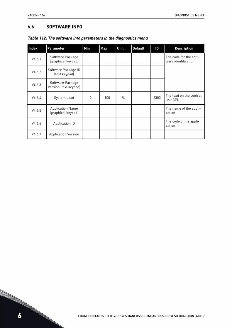
6.6 SOFTWARE INFO
Table 112: The software info parameters in the diagnostics menu
Index Parameter Min Max Unit Default ID Description
V4.6.1 Software Package(graphical keypad)
The code for the soft-ware identification
V4.6.2 Software Package ID(text keypad)
V4.6.3 Software PackageVersion (text keypad)
V4.6.4 System Load 0 100 % 2300 The load on the controlunit CPU
V4.6.5 Application Name(graphical keypad)
The name of the appli-cation
V4.6.6 Application ID The code of the appli-cation
V4.6.7 Application Version
VACON · 166 DIAGNOSTICS MENU
6 LOCAL CONTACTS: HTTP://DRIVES.DANFOSS.COM/DANFOSS-DRIVES/LOCAL-CONTACTS/

7 I/O AND HARDWARE MENUIn the I/O and Hardware menu, there are different settings that are related to the options.The values in this menu are raw values, that is, they are not scaled by the application.
7.1 BASIC I/O
In the Basic I/O menu, you can monitor the statuses of the inputs and the outputs.
I/O AND HARDWARE MENU VACON · 167
LOCAL CONTACTS: HTTP://DRIVES.DANFOSS.COM/DANFOSS-DRIVES/LOCAL-CONTACTS/ 7
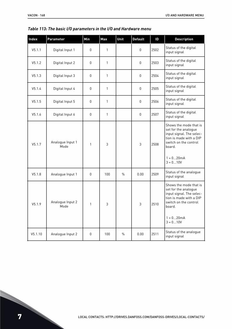
Table 113: The basic I/O parameters in the I/O and Hardware menu
Index Parameter Min Max Unit Default ID Description
V5.1.1 Digital Input 1 0 1 0 2502 Status of the digitalinput signal
V5.1.2 Digital Input 2 0 1 0 2503 Status of the digitalinput signal
V5.1.3 Digital Input 3 0 1 0 2504 Status of the digitalinput signal
V5.1.4 Digital Input 4 0 1 0 2505 Status of the digitalinput signal
V5.1.5 Digital Input 5 0 1 0 2506 Status of the digitalinput signal
V5.1.6 Digital Input 6 0 1 0 2507 Status of the digitalinput signal
V5.1.7 Analogue Input 1Mode 1 3 3 2508
Shows the mode that isset for the analogueinput signal. The selec-tion is made with a DIPswitch on the controlboard.
1 = 0...20mA3 = 0...10V
V5.1.8 Analogue Input 1 0 100 % 0.00 2509 Status of the analogueinput signal
V5.1.9 Analogue Input 2Mode 1 3 3 2510
Shows the mode that isset for the analogueinput signal. The selec-tion is made with a DIPswitch on the controlboard.
1 = 0...20mA3 = 0...10V
V5.1.10 Analogue Input 2 0 100 % 0.00 2511 Status of the analogueinput signal
VACON · 168 I/O AND HARDWARE MENU
7 LOCAL CONTACTS: HTTP://DRIVES.DANFOSS.COM/DANFOSS-DRIVES/LOCAL-CONTACTS/
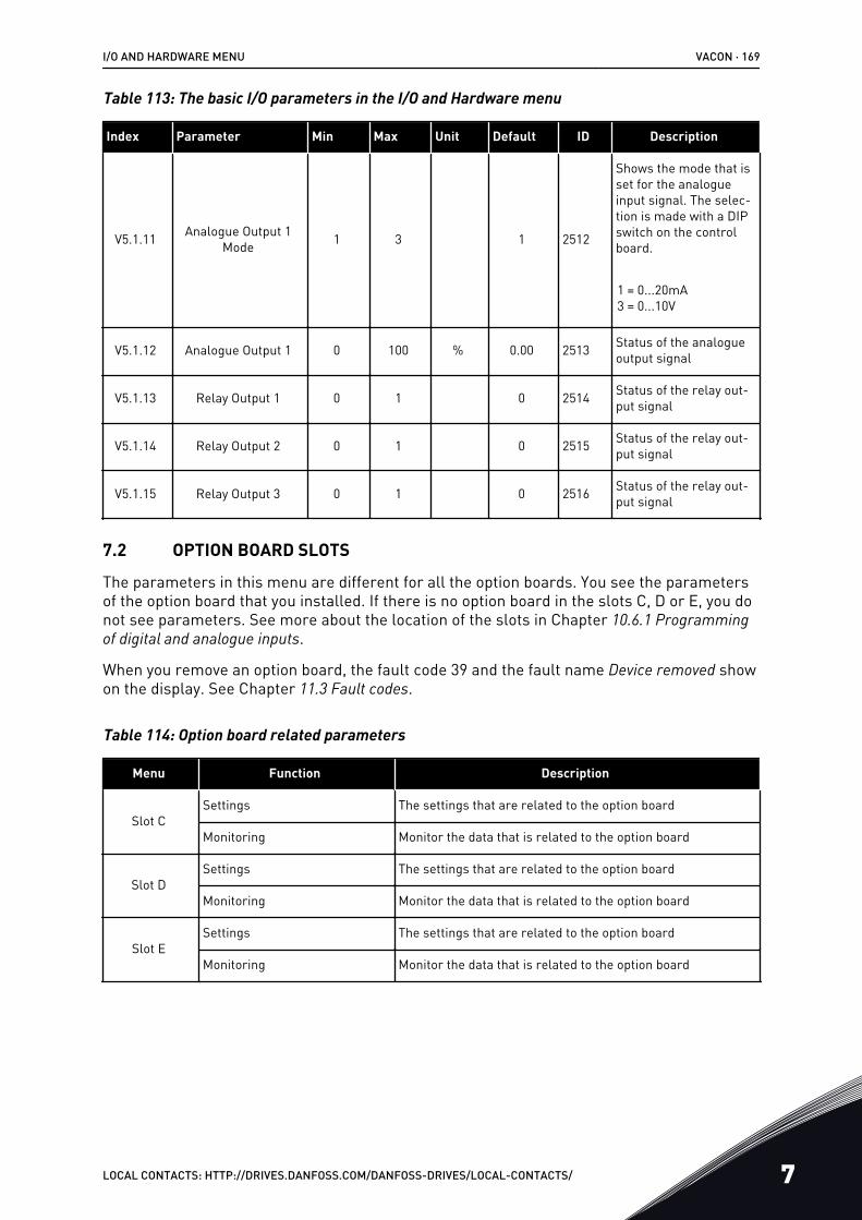
Table 113: The basic I/O parameters in the I/O and Hardware menu
Index Parameter Min Max Unit Default ID Description
V5.1.11 Analogue Output 1Mode 1 3 1 2512
Shows the mode that isset for the analogueinput signal. The selec-tion is made with a DIPswitch on the controlboard.
1 = 0...20mA3 = 0...10V
V5.1.12 Analogue Output 1 0 100 % 0.00 2513 Status of the analogueoutput signal
V5.1.13 Relay Output 1 0 1 0 2514 Status of the relay out-put signal
V5.1.14 Relay Output 2 0 1 0 2515 Status of the relay out-put signal
V5.1.15 Relay Output 3 0 1 0 2516 Status of the relay out-put signal
7.2 OPTION BOARD SLOTS
The parameters in this menu are different for all the option boards. You see the parametersof the option board that you installed. If there is no option board in the slots C, D or E, you donot see parameters. See more about the location of the slots in Chapter 10.6.1 Programming of digital and analogue inputs.
When you remove an option board, the fault code 39 and the fault name Device removed showon the display. See Chapter 11.3 Fault codes.
Table 114: Option board related parameters
Menu Function Description
Slot CSettings The settings that are related to the option board
Monitoring Monitor the data that is related to the option board
Slot DSettings The settings that are related to the option board
Monitoring Monitor the data that is related to the option board
Slot ESettings The settings that are related to the option board
Monitoring Monitor the data that is related to the option board
I/O AND HARDWARE MENU VACON · 169
LOCAL CONTACTS: HTTP://DRIVES.DANFOSS.COM/DANFOSS-DRIVES/LOCAL-CONTACTS/ 7
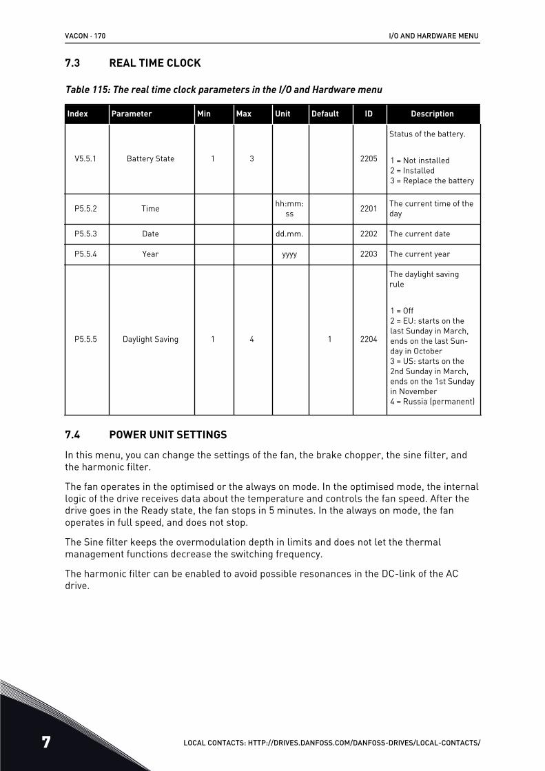
7.3 REAL TIME CLOCK
Table 115: The real time clock parameters in the I/O and Hardware menu
Index Parameter Min Max Unit Default ID Description
V5.5.1 Battery State 1 3 2205
Status of the battery.
1 = Not installed2 = Installed3 = Replace the battery
P5.5.2 Time hh:mm:ss 2201 The current time of the
day
P5.5.3 Date dd.mm. 2202 The current date
P5.5.4 Year yyyy 2203 The current year
P5.5.5 Daylight Saving 1 4 1 2204
The daylight savingrule
1 = Off2 = EU: starts on thelast Sunday in March,ends on the last Sun-day in October3 = US: starts on the2nd Sunday in March,ends on the 1st Sundayin November4 = Russia (permanent)
7.4 POWER UNIT SETTINGS
In this menu, you can change the settings of the fan, the brake chopper, the sine filter, andthe harmonic filter.
The fan operates in the optimised or the always on mode. In the optimised mode, the internallogic of the drive receives data about the temperature and controls the fan speed. After thedrive goes in the Ready state, the fan stops in 5 minutes. In the always on mode, the fanoperates in full speed, and does not stop.
The Sine filter keeps the overmodulation depth in limits and does not let the thermalmanagement functions decrease the switching frequency.
The harmonic filter can be enabled to avoid possible resonances in the DC-link of the ACdrive.
VACON · 170 I/O AND HARDWARE MENU
7 LOCAL CONTACTS: HTTP://DRIVES.DANFOSS.COM/DANFOSS-DRIVES/LOCAL-CONTACTS/

Table 116: Power unit settings
Index Parameter Min Max Unit Default ID Description
P5.6.1.1 Fan Control Mode 0 1 1 2377 0 = Always on1 = Optimised
P5.6.2.1 Brake Chopper Mode 0 3 0
0 = Disabled1 = Enabled (Run)2 = Enabled (Run &Stop)3 = Enabled (Run, notesting)
P5.6.4.1 Sine Filter 0 1 0 0 = Not used1 = In use
P5.6.5.1 Harmonic Filter 0 1 0 0 = Not used1 = In use
I/O AND HARDWARE MENU VACON · 171
LOCAL CONTACTS: HTTP://DRIVES.DANFOSS.COM/DANFOSS-DRIVES/LOCAL-CONTACTS/ 7
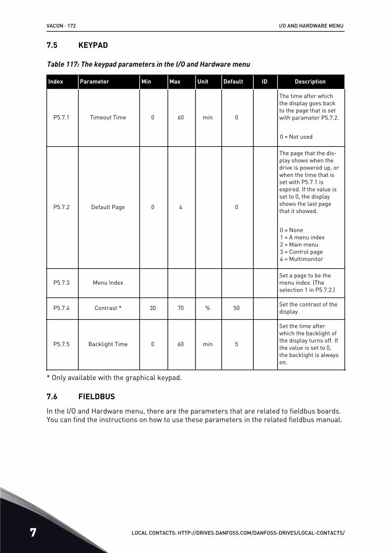
7.5 KEYPAD
Table 117: The keypad parameters in the I/O and Hardware menu
Index Parameter Min Max Unit Default ID Description
P5.7.1 Timeout Time 0 60 min 0
The time after whichthe display goes backto the page that is setwith parameter P5.7.2.
0 = Not used
P5.7.2 Default Page 0 4 0
The page that the dis-play shows when thedrive is powered up, orwhen the time that isset with P5.7.1 isexpired. If the value isset to 0, the displayshows the last pagethat it showed.
0 = None1 = A menu index2 = Main menu3 = Control page4 = Multimonitor
P5.7.3 Menu IndexSet a page to be themenu index. (Theselection 1 in P5.7.2.)
P5.7.4 Contrast * 30 70 % 50 Set the contrast of thedisplay.
P5.7.5 Backlight Time 0 60 min 5
Set the time afterwhich the backlight ofthe display turns off. Ifthe value is set to 0,the backlight is alwayson.
* Only available with the graphical keypad.
7.6 FIELDBUS
In the I/O and Hardware menu, there are the parameters that are related to fieldbus boards.You can find the instructions on how to use these parameters in the related fieldbus manual.
VACON · 172 I/O AND HARDWARE MENU
7 LOCAL CONTACTS: HTTP://DRIVES.DANFOSS.COM/DANFOSS-DRIVES/LOCAL-CONTACTS/
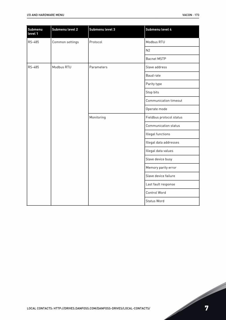
Submenulevel 1
Submenu level 2 Submenu level 3 Submenu level 4
RS-485 Common settings Protocol Modbus RTU
N2
Bacnet MSTP
RS-485 Modbus RTU Parameters Slave address
Baud rate
Parity type
Stop bits
Communication timeout
Operate mode
Monitoring Fieldbus protocol status
Communication status
Illegal functions
Illegal data addresses
Illegal data values
Slave device busy
Memory parity error
Slave device failure
Last fault response
Control Word
Status Word
I/O AND HARDWARE MENU VACON · 173
LOCAL CONTACTS: HTTP://DRIVES.DANFOSS.COM/DANFOSS-DRIVES/LOCAL-CONTACTS/ 7

Submenulevel 1
Submenu level 2 Submenu level 3 Submenu level 4
RS-485 N2 Parameters Slave address
Communication timeout
Monitoring Fieldbus protocol status
Communication status
Invalid data
Invalid commands
Command not accepted
Control word
Status word
RS-485 Bacnet MSTP Parameters Baud rate
Autobauding
MAC address
Instance number
Communication timeout
Monitoring Fieldbus protocol status
Communication status
Actual instance number
Fault code
Control word
Status word
Ethernet Common settings IP address mode
Fixed IP IP address
Subnet mask
Default gateway
IP address
Subnet mask
Default gateway
MAC address
VACON · 174 I/O AND HARDWARE MENU
7 LOCAL CONTACTS: HTTP://DRIVES.DANFOSS.COM/DANFOSS-DRIVES/LOCAL-CONTACTS/
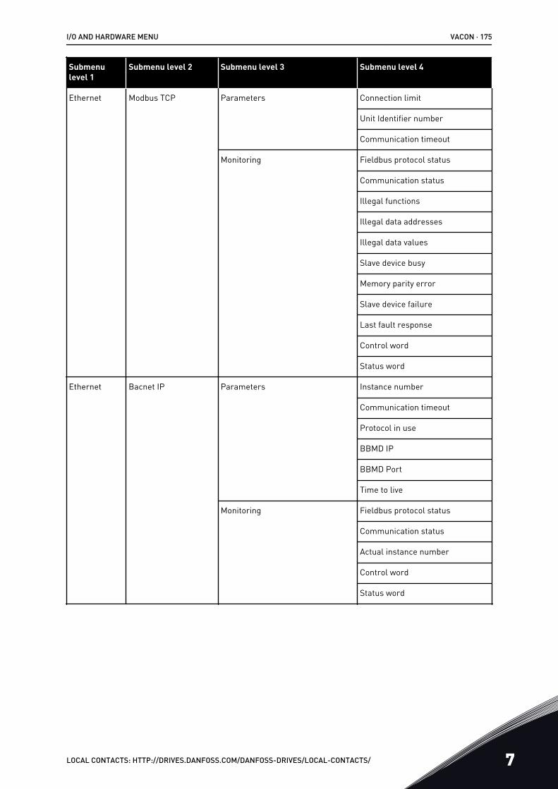
Submenulevel 1
Submenu level 2 Submenu level 3 Submenu level 4
Ethernet Modbus TCP Parameters Connection limit
Unit Identifier number
Communication timeout
Monitoring Fieldbus protocol status
Communication status
Illegal functions
Illegal data addresses
Illegal data values
Slave device busy
Memory parity error
Slave device failure
Last fault response
Control word
Status word
Ethernet Bacnet IP Parameters Instance number
Communication timeout
Protocol in use
BBMD IP
BBMD Port
Time to live
Monitoring Fieldbus protocol status
Communication status
Actual instance number
Control word
Status word
I/O AND HARDWARE MENU VACON · 175
LOCAL CONTACTS: HTTP://DRIVES.DANFOSS.COM/DANFOSS-DRIVES/LOCAL-CONTACTS/ 7
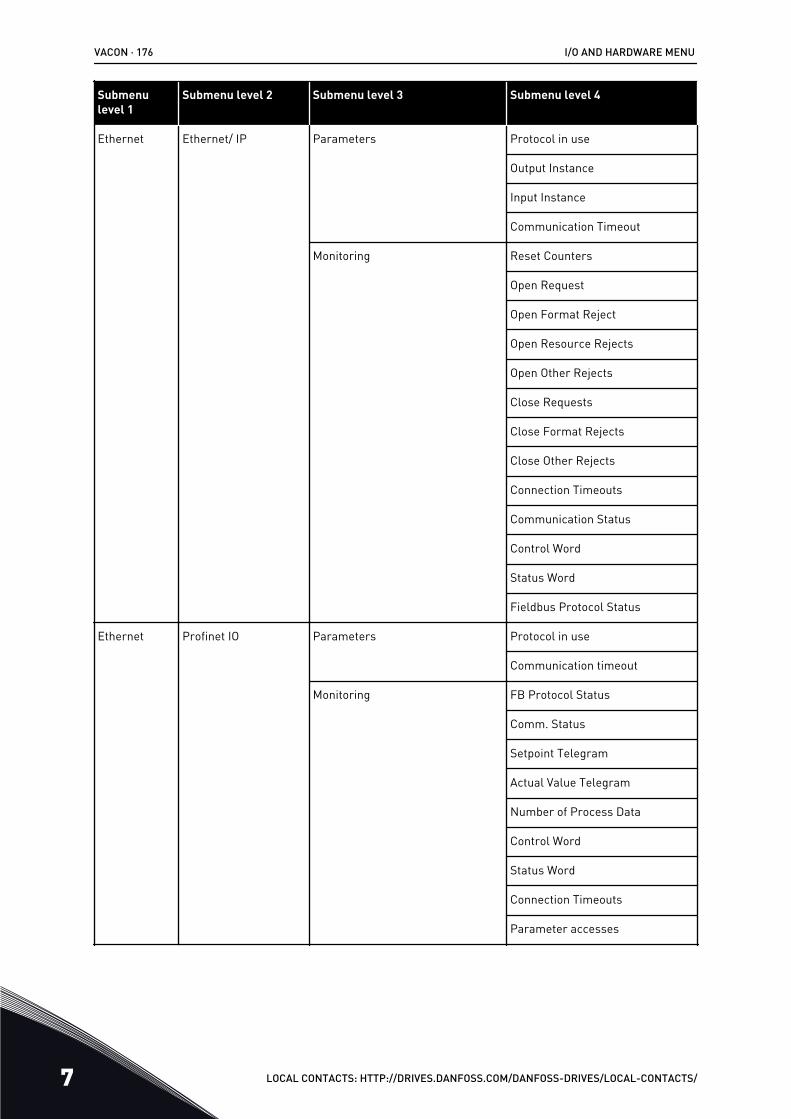
Submenulevel 1
Submenu level 2 Submenu level 3 Submenu level 4
Ethernet Ethernet/ IP Parameters Protocol in use
Output Instance
Input Instance
Communication Timeout
Monitoring Reset Counters
Open Request
Open Format Reject
Open Resource Rejects
Open Other Rejects
Close Requests
Close Format Rejects
Close Other Rejects
Connection Timeouts
Communication Status
Control Word
Status Word
Fieldbus Protocol Status
Ethernet Profinet IO Parameters Protocol in use
Communication timeout
Monitoring FB Protocol Status
Comm. Status
Setpoint Telegram
Actual Value Telegram
Number of Process Data
Control Word
Status Word
Connection Timeouts
Parameter accesses
VACON · 176 I/O AND HARDWARE MENU
7 LOCAL CONTACTS: HTTP://DRIVES.DANFOSS.COM/DANFOSS-DRIVES/LOCAL-CONTACTS/
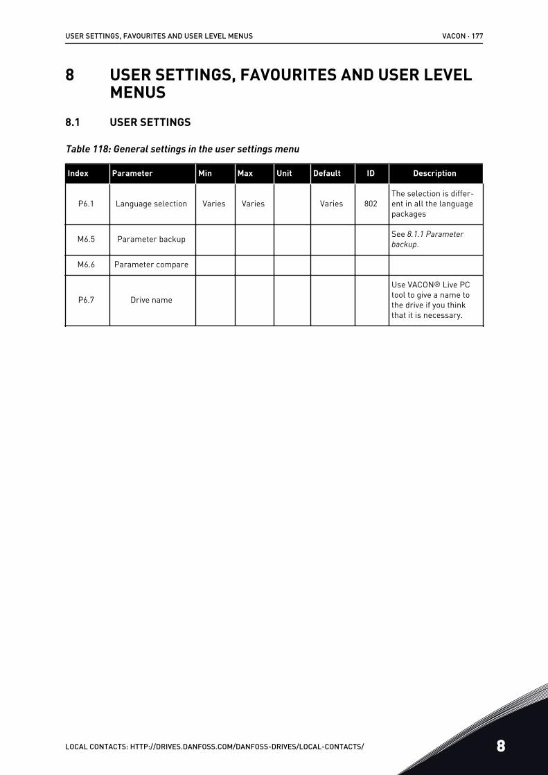
8 USER SETTINGS, FAVOURITES AND USER LEVELMENUS
8.1 USER SETTINGS
Table 118: General settings in the user settings menu
Index Parameter Min Max Unit Default ID Description
P6.1 Language selection Varies Varies Varies 802The selection is differ-ent in all the languagepackages
M6.5 Parameter backup See 8.1.1 Parameter backup.
M6.6 Parameter compare
P6.7 Drive name
Use VACON® Live PCtool to give a name tothe drive if you thinkthat it is necessary.
USER SETTINGS, FAVOURITES AND USER LEVEL MENUS VACON · 177
LOCAL CONTACTS: HTTP://DRIVES.DANFOSS.COM/DANFOSS-DRIVES/LOCAL-CONTACTS/ 8
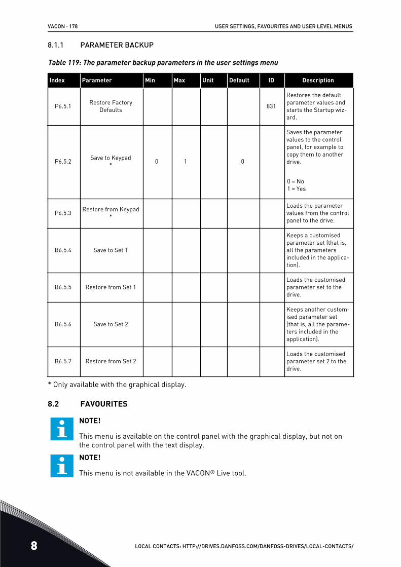
8.1.1 PARAMETER BACKUP
Table 119: The parameter backup parameters in the user settings menu
Index Parameter Min Max Unit Default ID Description
P6.5.1 Restore FactoryDefaults 831
Restores the defaultparameter values andstarts the Startup wiz-ard.
P6.5.2 Save to Keypad* 0 1 0
Saves the parametervalues to the controlpanel, for example tocopy them to anotherdrive.
0 = No1 = Yes
P6.5.3 Restore from Keypad*
Loads the parametervalues from the controlpanel to the drive.
B6.5.4 Save to Set 1
Keeps a customisedparameter set (that is,all the parametersincluded in the applica-tion).
B6.5.5 Restore from Set 1Loads the customisedparameter set to thedrive.
B6.5.6 Save to Set 2
Keeps another custom-ised parameter set(that is, all the parame-ters included in theapplication).
B6.5.7 Restore from Set 2Loads the customisedparameter set 2 to thedrive.
* Only available with the graphical display.
8.2 FAVOURITES
NOTE!
This menu is available on the control panel with the graphical display, but not onthe control panel with the text display.NOTE!
This menu is not available in the VACON® Live tool.
VACON · 178 USER SETTINGS, FAVOURITES AND USER LEVEL MENUS
8 LOCAL CONTACTS: HTTP://DRIVES.DANFOSS.COM/DANFOSS-DRIVES/LOCAL-CONTACTS/
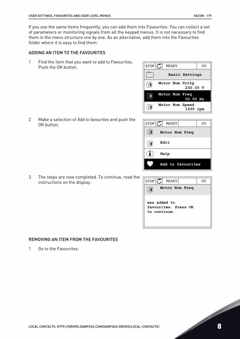
If you use the same items frequently, you can add them into Favourites. You can collect a setof parameters or monitoring signals from all the keypad menus. It is not necessary to findthem in the menu structure one by one. As an alternative, add them into the Favouritesfolder where it is easy to find them.
ADDING AN ITEM TO THE FAVOURITES
1 Find the item that you want to add to Favourites.Push the OK button. STOP READY I/O
Basic Settings
Motor Nom Freq
Motor Nom Speed
Motor Nom Voltg230.00 V
50.00 Hz
1430 rpm
2 Make a selection of Add to favourites and push theOK button. STOP READY I/O
Motor Nom Freq
Edit
Help
Add to favourites
3 The steps are now completed. To continue, read theinstructions on the display. STOP READY I/O
Motor Nom Freq
was added tofavourites. Press OKto continue.
REMOVING AN ITEM FROM THE FAVOURITES
1 Go to the Favourites.
USER SETTINGS, FAVOURITES AND USER LEVEL MENUS VACON · 179
LOCAL CONTACTS: HTTP://DRIVES.DANFOSS.COM/DANFOSS-DRIVES/LOCAL-CONTACTS/ 8
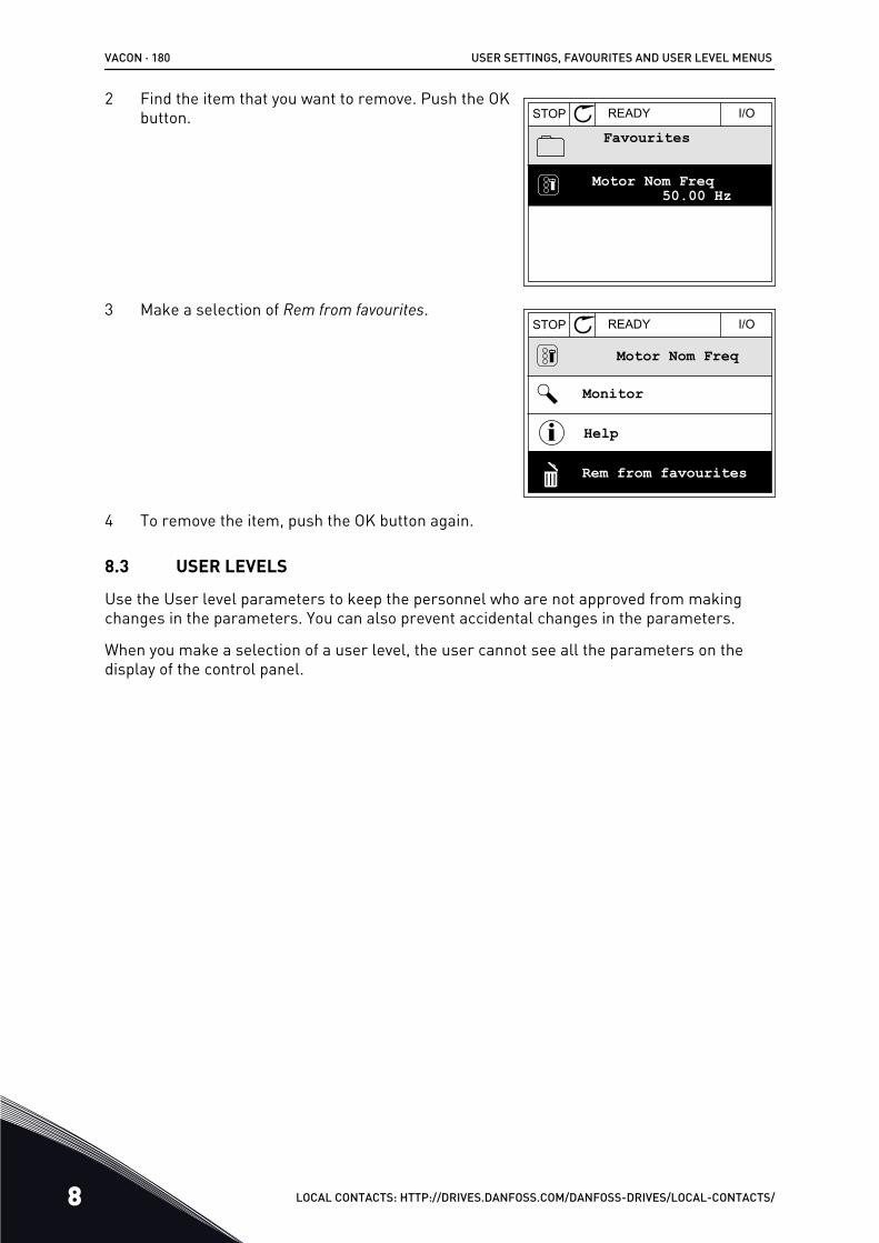
2 Find the item that you want to remove. Push the OKbutton. STOP READY I/O
Favourites
Motor Nom Freq50.00 Hz
3 Make a selection of Rem from favourites.STOP READY I/O
Motor Nom Freq
Rem from favourites
Help
Monitor
4 To remove the item, push the OK button again.
8.3 USER LEVELS
Use the User level parameters to keep the personnel who are not approved from makingchanges in the parameters. You can also prevent accidental changes in the parameters.
When you make a selection of a user level, the user cannot see all the parameters on thedisplay of the control panel.
VACON · 180 USER SETTINGS, FAVOURITES AND USER LEVEL MENUS
8 LOCAL CONTACTS: HTTP://DRIVES.DANFOSS.COM/DANFOSS-DRIVES/LOCAL-CONTACTS/
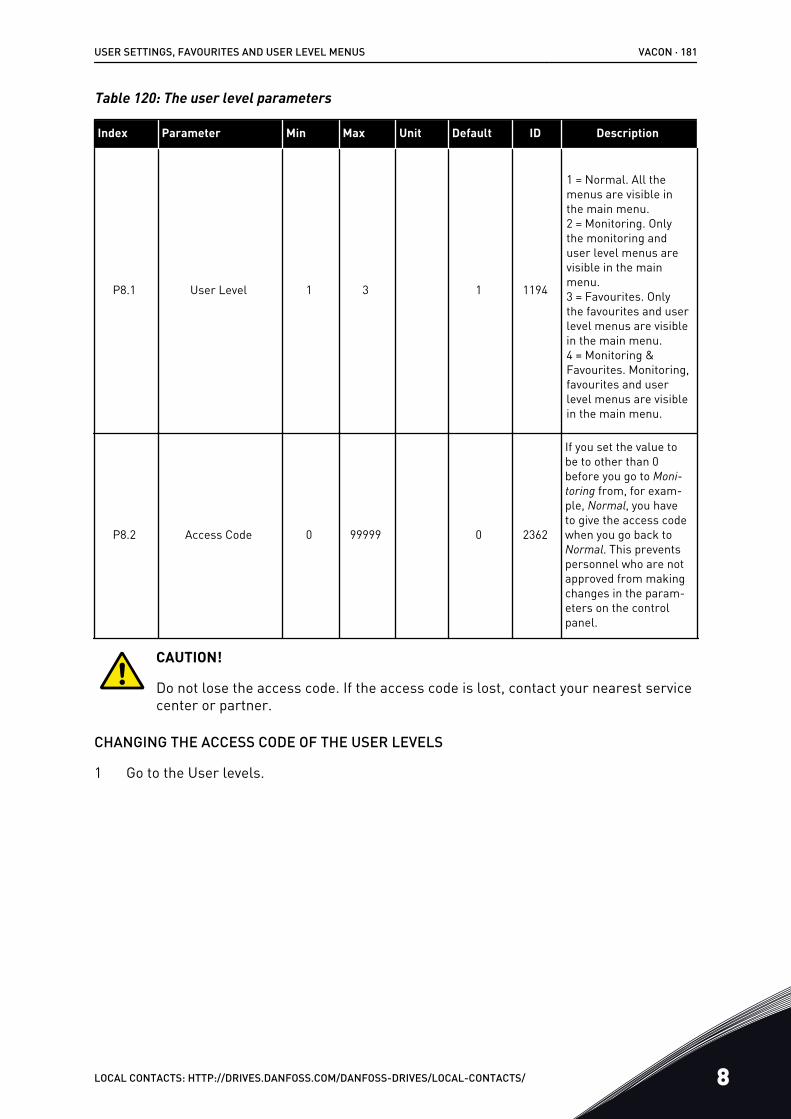
Table 120: The user level parameters
Index Parameter Min Max Unit Default ID Description
P8.1 User Level 1 3 1 1194
1 = Normal. All themenus are visible inthe main menu.2 = Monitoring. Onlythe monitoring anduser level menus arevisible in the mainmenu.3 = Favourites. Onlythe favourites and userlevel menus are visiblein the main menu.4 = Monitoring &Favourites. Monitoring,favourites and userlevel menus are visiblein the main menu.
P8.2 Access Code 0 99999 0 2362
If you set the value tobe to other than 0before you go to Moni-toring from, for exam-ple, Normal, you haveto give the access codewhen you go back toNormal. This preventspersonnel who are notapproved from makingchanges in the param-eters on the controlpanel.
CAUTION!
Do not lose the access code. If the access code is lost, contact your nearest servicecenter or partner.
CHANGING THE ACCESS CODE OF THE USER LEVELS
1 Go to the User levels.
USER SETTINGS, FAVOURITES AND USER LEVEL MENUS VACON · 181
LOCAL CONTACTS: HTTP://DRIVES.DANFOSS.COM/DANFOSS-DRIVES/LOCAL-CONTACTS/ 8
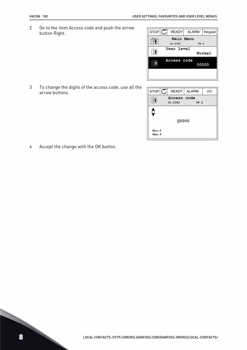
2 Go to the item Access code and push the arrowbutton Right. STOP READY ALARM Keypad
Main Menu
NormalUser level
00000Access code
P8.2ID:2362
3 To change the digits of the access code, use all thearrow buttons. STOP READY ALARM I/O
ID:2362 P8.2Access code
Min:0Max:9
00000
4 Accept the change with the OK button.
VACON · 182 USER SETTINGS, FAVOURITES AND USER LEVEL MENUS
8 LOCAL CONTACTS: HTTP://DRIVES.DANFOSS.COM/DANFOSS-DRIVES/LOCAL-CONTACTS/
9 MONITORING VALUE DESCRIPTIONSThis chapter gives you the basic descriptions of all monitoring values.
9.1 MULTIMONITOR
V2.1.1 FREQUENCY REFERENCE (ID 25)
This monitoring value shows the actual frequency reference to the motor control.The value is updated at 10 ms interval.
V2.1.2 OUTPUT FREQUENCY (ID 1)
This monitoring value shows the actual output frequency to the motor.
V2.1.3 MOTOR CURRENT (ID 3)
This monitoring value shows the measured current of the motor.The scaling of the value is different for different drive sizes.
V2.1.4 MOTOR SPEED (ID 2)
This monitoring value shows the actual speed of the motor in rpm (calculated value).
V2.1.5 MOTOR TORQUE (ID 4)
This monitoring value shows the actual torque of the motor (calculated value).
V2.1.6 MOTOR POWER (ID 5)
This monitoring value shows the actual shaft power of the motor (calculated value) as apercentage of the motor nominal power.
V2.1.7 MOTOR VOLTAGE (ID 6)
This monitoring value shows the actual output voltage to the motor.
V2.1.8 DC-LINK VOLTAGE (ID 7)
This monitoring value shows the measured voltage in the DC-link of the drive.
V2.1.9 UNIT TEMPERATURE (ID 8)
This monitoring value shows the measured heatsink temperature of the drive.The unit of measurement is degrees celsius or fahrenheit, depending on the 'C/F Selection'parameter value.
MONITORING VALUE DESCRIPTIONS VACON · 183
LOCAL CONTACTS: HTTP://DRIVES.DANFOSS.COM/DANFOSS-DRIVES/LOCAL-CONTACTS/ 9
9.2 BASIC
V2.3.1 OUTPUT FREQUENCY (ID 1)
This monitoring value shows the actual output frequency to the motor.
V2.3.2 FREQUENCY REFERENCE (ID 25)
This monitoring value shows the actual frequency reference to the motor control.The value is updated at 10 ms interval.
V2.3.3 MOTOR SPEED (ID 2)
This monitoring value shows the actual speed of the motor in rpm (calculated value).
V2.3.4 MOTOR CURRENT (ID 3)
This monitoring value shows the measured current of the motor.The scaling of the value is different for different drive sizes.
V2.3.5 MOTOR TORQUE (ID 4)
This monitoring value shows the actual torque of the motor (calculated value).
V2.3.7 MOTOR SHAFT POWER (ID 5)
This monitoring value shows the actual shaft power of the motor (calculated value) as apercentage of the motor nominal power.
V2.3.8 MOTOR SHAFT POWER (ID 73)
This monitoring value shows the actual shaft power of the motor (calculated value).The unit of measurement is kW or hp, depending on the 'kW/hp Selection' parameter value.
The amount of decimals in the value of this monitoring value varies depending on the size ofthe AC drive. In fieldbus control ID 15592 can be mapped as Process Data Out to determinehow many decimals are used. The last significant digit tells the amount of decimals.
V2.3.9 MOTOR VOLTAGE (ID 6)
This monitoring value shows the actual output voltage to the motor.
V2.3.10 DC LINK VOLTAGE (ID 7)
This monitoring value shows the measured voltage in the DC-link of the drive.
V2.3.11 UNIT TEMPERATURE (ID 8)
This monitoring value shows the measured heatsink temperature of the drive.The unit of the monitoring value is celsius degrees or fahrenheit degrees, depending on the'C/F Selection' parameter value.
VACON · 184 MONITORING VALUE DESCRIPTIONS
9 LOCAL CONTACTS: HTTP://DRIVES.DANFOSS.COM/DANFOSS-DRIVES/LOCAL-CONTACTS/
V2.3.12 MOTOR TEMPERATURE (ID 9)
This monitoring value shows the calculated motor temperature in percentage of the nominalworking temperature.When the value rises above 105%, motor thermal protection fault occurs.
V2.3.13 MOTOR PREHEAT (ID 1228)
This monitoring value shows the status of the motor preheat function.
V2.3.14 TORQUE REFERENCE (ID 18)
This monitoring value shows the final torque reference for motor control.
9.3 I/O
V2.4.1 SLOTA DIN 1,2,3 (ID 15)
This monitoring value shows the status of the digital inputs 1-3 in slot A (standard I/O).
V2.4.2 SLOTA DIN 4,5,6 (ID 16)
This monitoring value shows the status of the digital inputs 4-6 in slot A (standard I/O).
V2.4.3 SLOTB RO 1,2,3 (ID 17)
This monitoring value shows the status of the relay outputs 1-3 in slot B.
V2.4.4 ANALOG INPUT 1 (ID 59)
This monitoring value shows the value of the analogue input signal as a percentage of theused range.
V2.4.5 ANALOG INPUT 2 (ID 60)
This monitoring value shows the value of the analogue input signal as a percentage of theused range.
V2.4.6 ANALOG INPUT 3 (ID 61)
This monitoring value shows the value of the analogue input signal as a percentage of theused range.
V2.4.7 ANALOG INPUT 4 (ID 62)
This monitoring value shows the value of the analogue input signal as a percentage of theused range.
V2.4.8 ANALOG INPUT 5 (ID 75)
This monitoring value shows the value of the analogue input signal as a percentage of theused range.
MONITORING VALUE DESCRIPTIONS VACON · 185
LOCAL CONTACTS: HTTP://DRIVES.DANFOSS.COM/DANFOSS-DRIVES/LOCAL-CONTACTS/ 9
V2.4.9 ANALOG INPUT 6 (ID 76)
This monitoring value shows the value of the analogue input signal as a percentage of theused range.
V2.4.10 SLOTA AO 1 (ID 81)
This monitoring value shows the value of the analogue output as a percentage of the usedrange.
9.4 TEMPERATURE INPUTS
The monitoring values related to temperature input settings are only available if a B8 or BHoption board is installed.
V2.5.1 TEMPERATURE INPUT 1 (ID 50)
This monitoring value shows the measured value of the temperature.The unit of the monitoring value is celsius degrees or fahrenheit degrees, depending on the'C/F Selection' parameter value.
NOTE!
The list of temperature inputs is made of the first 6 available temperature inputs.The list starts from slot A and ends in slot E. If an input is available but no sensor isconnected, the list shows the maximum value because the measured resistance isendless. To make the value go to its minimum value, hardwire the input.
V2.5.2 TEMPERATURE INPUT 2 (ID 51)
This monitoring value shows the measured value of the temperature.The unit of the monitoring value is celsius degrees or fahrenheit degrees, depending on the'C/F Selection' parameter value.
V2.5.3 TEMPERATURE INPUT 3 (ID 52)
This monitoring value shows the measured value of the temperature.The unit of the monitoring value is celsius degrees or fahrenheit degrees, depending on the'C/F Selection' parameter value.
V2.5.4 TEMPERATURE INPUT 4 (ID 69)
This monitoring value shows the measured value of the temperature.The unit of the monitoring value is celsius degrees or fahrenheit degrees, depending on the'C/F Selection' parameter value.
V2.5.5 TEMPERATURE INPUT 5 (ID 70)
This monitoring value shows the measured value of the temperature.The unit of the monitoring value is celsius degrees or fahrenheit degrees, depending on the'C/F Selection' parameter value.
VACON · 186 MONITORING VALUE DESCRIPTIONS
9 LOCAL CONTACTS: HTTP://DRIVES.DANFOSS.COM/DANFOSS-DRIVES/LOCAL-CONTACTS/
V2.5.6 TEMPERATURE INPUT 6 (ID 71)
This monitoring value shows the measured value of the temperature.The unit of the monitoring value is celsius degrees or fahrenheit degrees, depending on the'C/F Selection' parameter value.
9.5 EXTRAS AND ADVANCED
V2.6.1 DRIVE STATUS WORD (ID 43)
This monitoring value shows the bit-coded status of drive.
V2.6.2 READY STATUS (ID 78)
This monitoring value shows the bit-coded data about the Ready criteria of the drive.This data is useful for monitoring when the drive is not in the Ready state.
NOTE!
The values are visible as checkboxes on the graphical display. If a box is selected,the value is active.
V2.6.3 APPLICATION STATUS WORD 1 (ID 89)
This monitoring value shows the bit-coded statuses of the application.
NOTE!
The values are visible as checkboxes on the graphical display. If a box is selected,the value is active.
V2.6.4 APPLICATION STATUS WORD 2 (ID 90)
This monitoring value shows the bit-coded statuses of the application.
NOTE!
The values are visible as checkboxes on the graphical display. If a box is selected,the value is active.
V2.6.5 DIN STATUS WORD 1 (ID 56)
This monitoring value shows the bit-coded status of the digital input signals.The monitoring value is a 16 bit word, where each bit shows the status of 1 digital input.From each slot, 6 digital inputs are read. Word 1 starts from the input 1 in slot A (bit0) andends with input 4 in slot C (bit15).
V2.6.6 DIN STATUS WORD 2 (ID 57)
This monitoring value shows the bit-coded status of the digital input signals.
MONITORING VALUE DESCRIPTIONS VACON · 187
LOCAL CONTACTS: HTTP://DRIVES.DANFOSS.COM/DANFOSS-DRIVES/LOCAL-CONTACTS/ 9
The monitoring value is a 16 bit word, where each bit shows the status of 1 digital input.From each slot, 6 digital inputs are read. Word 2 starts from the input 5 in slot C (bit0) andends with input 6 in slot E (bit13).
V2.6.7 MOTOR CURRENT 1 DECI (ID 45)
This monitoring value shows the measured current of the motor with the fixed number ofdecimals and that is less filtered.This monitoring value can be used for example with fieldbus to get the correct value so thatthe enclosure size does not have an effect, or for monitoring when less filtering time isneeded for the motor current.
V2.6.8 FREQUENCY REFERENCE SOURCE (ID 1495)
This monitoring value shows the momentary frequency reference source.
V2.6.9 LAST ACTIVE FAULT CODE (ID 37)
This monitoring value shows the fault code of latest activated fault that is not reset.
V2.6.10 LAST ACTIVE FAULT ID (ID 95)
This monitoring value shows the fault ID of latest activated fault that is not reset.
V2.6.11 LAST ACTIVE ALARM CODE (ID 74)
This monitoring value shows the alarm code of latest activated alarm that is not reset.
V2.6.12 LAST ACTIVE ALARM ID (ID 94)
This monitoring value shows the alarm ID of latest activated alarm that is not reset.
V2.6.13 MOTOR REGULATOR STATUS (ID 77)
This monitoring value shows the bit-coded status of the motor limit controllers.
NOTE!
The values are visible as checkboxes on the graphical display. If a box is selected,the limit controller is active.
V2.6.14 MOTOR SHAFT POWER 1 DECIMAL (ID 98)
This monitoring value shows the actual shaft power of the motor (calculated value with onedecimal). The unit of measurement is kW or hp, depending on the 'kW/hp Selection'parameter value.
9.6 TIMER FUNCTIONS
V2.7.1 TC 1, TC 2, TC 3 (ID 1441)
This monitoring value shows the status of the time channels 1, 2 and 3.
VACON · 188 MONITORING VALUE DESCRIPTIONS
9 LOCAL CONTACTS: HTTP://DRIVES.DANFOSS.COM/DANFOSS-DRIVES/LOCAL-CONTACTS/
V2.7.2 INTERVAL 1 (ID 1442)
This monitoring value shows the status of the interval function.
V2.7.3 INTERVAL 2 (ID 1443)
This monitoring value shows the status of the interval function.
V2.7.4 INTERVAL 3 (ID 1444)
This monitoring value shows the status of the interval function.
V2.7.5 INTERVAL 4 (ID 1445)
This monitoring value shows the status of the interval function.
V2.7.6 INTERVAL 5 (ID 1446)
This monitoring value shows the status of the interval function.
V2.7.7 TIMER 1 (ID 1447)
The monitoring value shows the remaining time on the timer if the timer is active.
V2.7.8 TIMER 2 (ID 1448)
The monitoring value shows the remaining time on the timer if the timer is active.
V2.7.9 TIMER 3 (ID 1449)
The monitoring value shows the remaining time on the timer if the timer is active.
V2.7.10 REAL TIME CLOCK (ID 1450)
This monitoring value shows the actual time of the real time clock in a format of hh:mm:ss.
9.7 PID CONTROLLER
V2.8.1 PID SETPOINT (ID 20)
This monitoring value shows the value of the PID setpoint signal in process units.You can use the parameter P3.13.1.7 to select the process unit (See 10.14.1 Basic settings).
V2.8.2 PID FEEDBACK (ID 21)
This monitoring value shows the value of the PID feedback signal in process units.You can use the parameter P3.13.1.7 to select the process unit (See 10.14.1 Basic settings).
V2.8.3 PID ERROR (ID 22)
This monitoring value shows the error value of the PID controller.The error value is the deviation of PID feedback from the PID setpoint in process unit.You can use the parameter P3.13.1.7 to select the process unit (See 10.14.1 Basic settings).
MONITORING VALUE DESCRIPTIONS VACON · 189
LOCAL CONTACTS: HTTP://DRIVES.DANFOSS.COM/DANFOSS-DRIVES/LOCAL-CONTACTS/ 9
V2.8.4 PID OUTPUT (ID 23)
This monitoring value shows the output of the PID controller as a percentage (0-100%).You can give this value to the motor control (frequency reference) or to an analogue output.
V2.8.5 PID STATUS (ID 24)
This monitoring value shows the state of the PID controller.
9.8 EXTERNAL PID CONTROLLER
V2.9.1 EXTPID SETPOINT (ID 83)
This monitoring value shows the value of the PID setpoint signal in process units.You can use the parameter P3.14.1.10 to select the process unit (See 10.14.1 Basic settings).
V2.9.2 EXTPID FEEDBACK (ID 84)
This monitoring value shows the value of the PID feedback signal in process units.You can use the parameter P3.14.1.10 to select the process unit (See 10.14.1 Basic settings).
V2.9.3 EXTPID ERROR (ID 85)
This monitoring value shows the error value of the PID controller.The error value is the deviation of PID feedback from the PID setpoint in process unit.You can use the parameter P3.14.1.10 to select the process unit (See 10.14.1 Basic settings).
V2.9.4 EXTPID OUTPUT (ID 86)
This monitoring value shows the output of the PID controller as a percentage (0-100%).You can give this value to, for example, the analogue output.
V2.9.5 EXTPID STATUS (ID 87)
This monitoring value shows the state of the PID controller.
9.9 MULTI-PUMP
V2.10.1 MOTORS RUNNING (ID 30)
This monitoring value shows the actual number of motors that operate in the Multi-pumpsystem.
V2.10.2 AUTOCHANGE (ID 1114)
This monitoring value shows the status of the autochange requested.
VACON · 190 MONITORING VALUE DESCRIPTIONS
9 LOCAL CONTACTS: HTTP://DRIVES.DANFOSS.COM/DANFOSS-DRIVES/LOCAL-CONTACTS/
9.10 MAINTENANCE COUNTERS
V2.11.1 MAINTENANCE COUNTER 1 (ID 1101)
This monitoring value shows the status of the maintenance counter.The status of the maintenance counter is shown as revolutions multiplied by 1000, or inhours. For the configuration and activation of this counter, see 10.17 Maintenance counters.
9.11 FIELDBUS DATA
V2.12.1 FB CONTROL WORD (ID 874)
This monitoring value shows the status of the fieldbus control word that the application usesin bypass mode.Depending on the fieldbus type or profile, the data that is received from the fieldbus can bemodified before it is sent to the application.
MONITORING VALUE DESCRIPTIONS VACON · 191
LOCAL CONTACTS: HTTP://DRIVES.DANFOSS.COM/DANFOSS-DRIVES/LOCAL-CONTACTS/ 9
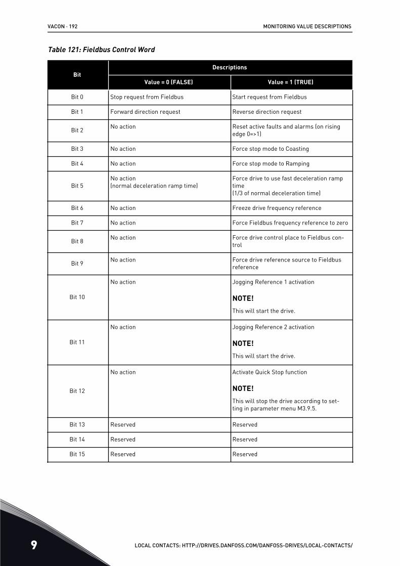
Table 121: Fieldbus Control Word
BitDescriptions
Value = 0 (FALSE) Value = 1 (TRUE)
Bit 0 Stop request from Fieldbus Start request from Fieldbus
Bit 1 Forward direction request Reverse direction request
Bit 2 No action Reset active faults and alarms (on risingedge 0=>1)
Bit 3 No action Force stop mode to Coasting
Bit 4 No action Force stop mode to Ramping
Bit 5No action(normal deceleration ramp time)
Force drive to use fast deceleration ramptime(1/3 of normal deceleration time)
Bit 6 No action Freeze drive frequency reference
Bit 7 No action Force Fieldbus frequency reference to zero
Bit 8 No action Force drive control place to Fieldbus con-trol
Bit 9 No action Force drive reference source to Fieldbusreference
Bit 10
No action Jogging Reference 1 activation
NOTE!This will start the drive.
Bit 11
No action Jogging Reference 2 activation
NOTE!This will start the drive.
Bit 12
No action Activate Quick Stop function
NOTE!This will stop the drive according to set-ting in parameter menu M3.9.5.
Bit 13 Reserved Reserved
Bit 14 Reserved Reserved
Bit 15 Reserved Reserved
VACON · 192 MONITORING VALUE DESCRIPTIONS
9 LOCAL CONTACTS: HTTP://DRIVES.DANFOSS.COM/DANFOSS-DRIVES/LOCAL-CONTACTS/
V2.12.2 FB SPEED REFERENCE (ID 875)
This monitoring value shows the fieldbus frequency reference as a percentage of minimumfrequency to maximum frequency.The speed reference information is scaled between the minimum and the maximumfrequency at the moment when the application received it. You can change the minimum andthe maximum frequencies after the application received the reference without an effect onthe reference.
V2.12.3 FB DATA IN 1 (ID 876)
This monitoring value shows the raw value of process data in a 32-bit signed format.
V2.12.4 FB DATA IN 2 (ID 877)
This monitoring value shows the raw value of process data in a 32-bit signed format.
V2.12.5 FB DATA IN 3 (ID 878)
This monitoring value shows the raw value of process data in a 32-bit signed format.
V2.12.6 FB DATA IN 4 (ID 879)
This monitoring value shows the raw value of process data in a 32-bit signed format.
V2.12.7 FB DATA IN 5 (ID 880)
This monitoring value shows the raw value of process data in a 32-bit signed format.
V2.12.8 FB DATA IN 6 (ID 881)
This monitoring value shows the raw value of process data in a 32-bit signed format.
V2.12.9 FB DATA IN 7 (ID 882)
This monitoring value shows the raw value of process data in a 32-bit signed format.
V2.12.10 FB DATA IN 8 (ID 883)
This monitoring value shows the raw value of process data in a 32-bit signed format.
V2.12.11 FB STATUS WORD (ID 864)
This monitoring value shows the status of the fieldbus status word that the application usesin bypass mode.Depending on the fieldbus type or profile, the data can be modified before it is sent to thefieldbus.
MONITORING VALUE DESCRIPTIONS VACON · 193
LOCAL CONTACTS: HTTP://DRIVES.DANFOSS.COM/DANFOSS-DRIVES/LOCAL-CONTACTS/ 9
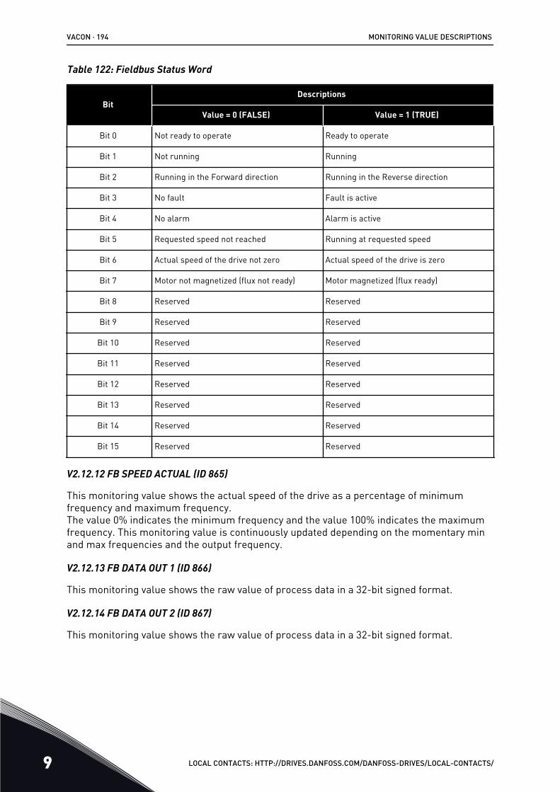
Table 122: Fieldbus Status Word
BitDescriptions
Value = 0 (FALSE) Value = 1 (TRUE)
Bit 0 Not ready to operate Ready to operate
Bit 1 Not running Running
Bit 2 Running in the Forward direction Running in the Reverse direction
Bit 3 No fault Fault is active
Bit 4 No alarm Alarm is active
Bit 5 Requested speed not reached Running at requested speed
Bit 6 Actual speed of the drive not zero Actual speed of the drive is zero
Bit 7 Motor not magnetized (flux not ready) Motor magnetized (flux ready)
Bit 8 Reserved Reserved
Bit 9 Reserved Reserved
Bit 10 Reserved Reserved
Bit 11 Reserved Reserved
Bit 12 Reserved Reserved
Bit 13 Reserved Reserved
Bit 14 Reserved Reserved
Bit 15 Reserved Reserved
V2.12.12 FB SPEED ACTUAL (ID 865)
This monitoring value shows the actual speed of the drive as a percentage of minimumfrequency and maximum frequency.The value 0% indicates the minimum frequency and the value 100% indicates the maximumfrequency. This monitoring value is continuously updated depending on the momentary minand max frequencies and the output frequency.
V2.12.13 FB DATA OUT 1 (ID 866)
This monitoring value shows the raw value of process data in a 32-bit signed format.
V2.12.14 FB DATA OUT 2 (ID 867)
This monitoring value shows the raw value of process data in a 32-bit signed format.
VACON · 194 MONITORING VALUE DESCRIPTIONS
9 LOCAL CONTACTS: HTTP://DRIVES.DANFOSS.COM/DANFOSS-DRIVES/LOCAL-CONTACTS/
V2.12.15 FB DATA OUT 3 (ID 868)
This monitoring value shows the raw value of process data in a 32-bit signed format.
V2.12.16 FB DATA OUT 4 (ID 869)
This monitoring value shows the raw value of process data in a 32-bit signed format.
V2.12.17 FB DATA OUT 5 (ID 870)
This monitoring value shows the raw value of process data in a 32-bit signed format.
V2.12.18 FB DATA OUT 6 (ID 871)
This monitoring value shows the raw value of process data in a 32-bit signed format.
V2.12.19 FB DATA OUT 7 (ID 872)
This monitoring value shows the raw value of process data in a 32-bit signed format.
V2.12.20 FB DATA OUT 8 (ID 873)
This monitoring value shows the raw value of process data in a 32-bit signed format.
MONITORING VALUE DESCRIPTIONS VACON · 195
LOCAL CONTACTS: HTTP://DRIVES.DANFOSS.COM/DANFOSS-DRIVES/LOCAL-CONTACTS/ 9
10 PARAMETER DESCRIPTIONSIn this chapter, you can find information on all the parameters of your VACON® 100application. If other information is necessary, see chapter 5 Parameters menu or contact yournearest distributor.
P1.2 APPLICATION (ID212)
Use this parameter to select the application configuration for the drive.The applications include preset application configurations, that is, sets of predefinedparameters. The selection of the application makes the commissioning of the drive easy andreduces the manual work with the parameters.
When the value of this parameter changes, a group of parameteres get their preset values.You can change the value of this parameter when you make the start up or thecommissioning of the drive.
If you use the control panel to change this parameter, an application wizard starts and helpsyou to set the basic parameters related to the application. The wizard does not start, if youuse the PC tool to change this parameter. You can find data about the application wizards inChapter 2 Wizards.
These applications are available:
0 = Standard1 = Local/Remote2 = Multi-step speed3 = PID control4 = Multi-purpose5 = Motor potentiometer
NOTE!
When you change the application, the contents of the Quick Setup menu change.
10.1 TREND CURVE
P2.2.2 SAMPLING INTERVAL (ID 2368)
Use this parameter to set the sampling interval.
P2.2.3 CHANNEL 1 MIN (ID 2369)
This parameter is used in scaling by default.Adjustments can be necessary.
P2.2.4 CHANNEL 1 MAX (ID 2370)
This parameter is used in scaling by default.Adjustments can be necessary.
VACON · 196 PARAMETER DESCRIPTIONS
10 LOCAL CONTACTS: HTTP://DRIVES.DANFOSS.COM/DANFOSS-DRIVES/LOCAL-CONTACTS/
P2.2.5 CHANNEL 2 MIN (ID 2371)
This parameter is used in scaling by default.Adjustments can be necessary.
P2.2.6 CHANNEL 2 MAX (ID 2372)
This parameter is used in scaling by default.Adjustments can be necessary.
P2.2.7 AUTOSCALE (ID 2373)
Use this parameter to set autoscaling on or off.If autoscaling is enabled, the signal is automatically scaled between the minimum andmaximum values.
10.2 MOTOR SETTINGS
10.2.1 MOTOR NAMEPLATE PARAMETERS
P3.1.1.1 MOTOR NOMINAL VOLTAGE (ID 110)
Find the value Un on the nameplate of the motor.Find out whether the motor connection is Delta or Star.
P3.1.1.2 MOTOR NOMINAL FREQUENCY (ID 111)
Find the value fn on the nameplate of the motor.When this parameter changes, parameters P3.1.4.2 Field Weakening Point Frequency andP3.1.4.3 Voltage at Field Weakening Point start automatically. The 2 parameters havedifferent values for each motor type. See the tables in P3.1.2.2 Motor Type (ID 650).
P3.1.1.3 MOTOR NOMINAL SPEED (ID 112)
Find the value nn on the nameplate of the motor.
P3.1.1.4 MOTOR NOMINAL CURRENT (ID 113)
Find the value In on the nameplate of the motor.
P3.1.1.5 MOTOR COS PHI (ID 120)
Find the value on the nameplate of the motor.
P3.1.1.6 MOTOR NOMINAL POWER (ID 116)
Find the value Pn on the nameplate of the motor.
PARAMETER DESCRIPTIONS VACON · 197
LOCAL CONTACTS: HTTP://DRIVES.DANFOSS.COM/DANFOSS-DRIVES/LOCAL-CONTACTS/ 10
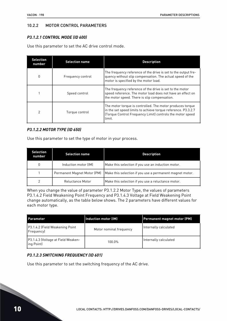
10.2.2 MOTOR CONTROL PARAMETERS
P3.1.2.1 CONTROL MODE (ID 600)
Use this parameter to set the AC drive control mode.
Selectionnumber Selection name Description
0 Frequency controlThe frequency reference of the drive is set to the output fre-quency without slip compensation. The actual speed of themotor is specified by the motor load.
1 Speed controlThe frequency reference of the drive is set to the motorspeed reference. The motor load does not have an effect onthe motor speed. There is slip compensation.
2 Torque control
The motor torque is controlled. The motor produces torquein the set speed limits to achieve torque reference. P3.3.2.7(Torque Control Frequency Limit) controls the motor speedlimit.
P3.1.2.2 MOTOR TYPE (ID 650)
Use this parameter to set the type of motor in your process.
Selectionnumber Selection name Description
0 Induction motor (IM) Make this selection if you use an induction motor.
1 Permanent Magnet Motor (PM) Make this selection if you use a permanent magnet motor.
2 Reluctance Motor Make this selection if you use a reluctance motor.
When you change the value of parameter P3.1.2.2 Motor Type, the values of parametersP3.1.4.2 Field Weakening Point Frequency and P3.1.4.3 Voltage at Field Weakening Pointchange automatically, as the table below shows. The 2 parameters have different values foreach motor type.
Parameter Induction motor (IM) Permanent magnet motor (PM)
P3.1.4.2 (Field Weakening PointFrequency) Motor nominal frequency Internally calculated
P3.1.4.3 (Voltage at Field Weaken-ing Point) 100.0% Internally calculated
P3.1.2.3 SWITCHING FREQUENCY (ID 601)
Use this parameter to set the switching frequency of the AC drive.
VACON · 198 PARAMETER DESCRIPTIONS
10 LOCAL CONTACTS: HTTP://DRIVES.DANFOSS.COM/DANFOSS-DRIVES/LOCAL-CONTACTS/
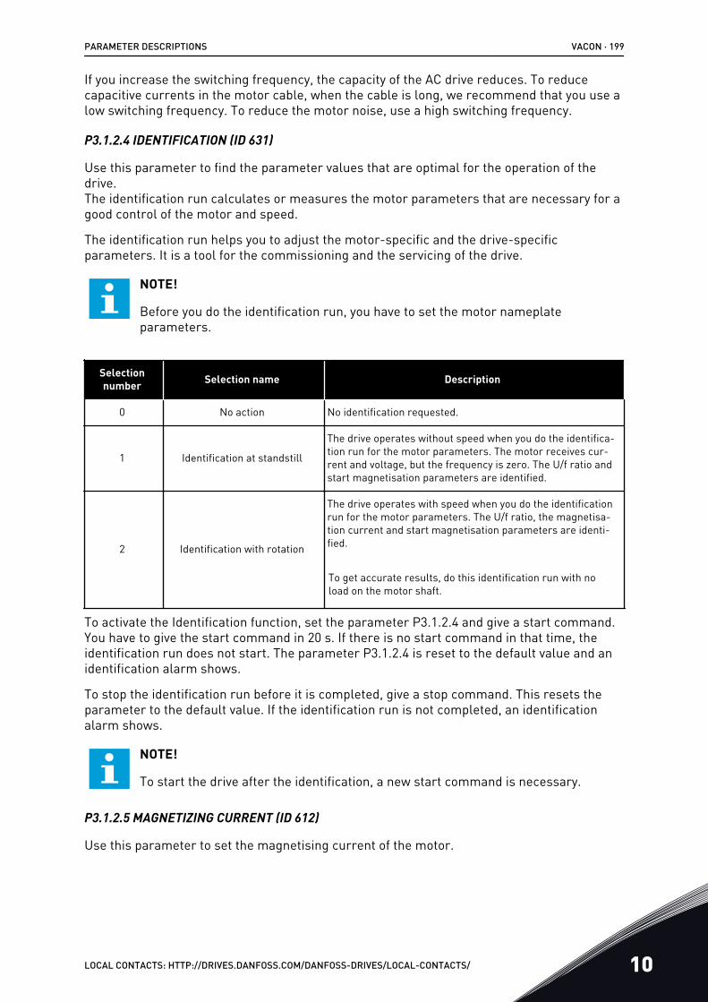
If you increase the switching frequency, the capacity of the AC drive reduces. To reducecapacitive currents in the motor cable, when the cable is long, we recommend that you use alow switching frequency. To reduce the motor noise, use a high switching frequency.
P3.1.2.4 IDENTIFICATION (ID 631)
Use this parameter to find the parameter values that are optimal for the operation of thedrive.The identification run calculates or measures the motor parameters that are necessary for agood control of the motor and speed.
The identification run helps you to adjust the motor-specific and the drive-specificparameters. It is a tool for the commissioning and the servicing of the drive.
NOTE!
Before you do the identification run, you have to set the motor nameplateparameters.
Selectionnumber Selection name Description
0 No action No identification requested.
1 Identification at standstill
The drive operates without speed when you do the identifica-tion run for the motor parameters. The motor receives cur-rent and voltage, but the frequency is zero. The U/f ratio andstart magnetisation parameters are identified.
2 Identification with rotation
The drive operates with speed when you do the identificationrun for the motor parameters. The U/f ratio, the magnetisa-tion current and start magnetisation parameters are identi-fied.
To get accurate results, do this identification run with noload on the motor shaft.
To activate the Identification function, set the parameter P3.1.2.4 and give a start command.You have to give the start command in 20 s. If there is no start command in that time, theidentification run does not start. The parameter P3.1.2.4 is reset to the default value and anidentification alarm shows.
To stop the identification run before it is completed, give a stop command. This resets theparameter to the default value. If the identification run is not completed, an identificationalarm shows.
NOTE!
To start the drive after the identification, a new start command is necessary.
P3.1.2.5 MAGNETIZING CURRENT (ID 612)
Use this parameter to set the magnetising current of the motor.
PARAMETER DESCRIPTIONS VACON · 199
LOCAL CONTACTS: HTTP://DRIVES.DANFOSS.COM/DANFOSS-DRIVES/LOCAL-CONTACTS/ 10
The magnetising current (no-load current) of the motor identifies the values of the U/fparameters if they are given before the identification run. If the value is set to 0, themagnetising current is calculated internally.
P3.1.2.6 MOTOR SWITCH (ID 653)
Use this parameter to enable the Motor Switch function.You can use the Motor Switch function, if the cable that connects the motor and the drive hasa motor switch. The operation of the motor switch makes sure that the motor is isolatedfrom the voltage source and does not start during the servicing.
To activate the function, set the parameter P3.1.2.6 to the value Enabled. The drive stopsautomatically when the motor switch is opened, and the drive starts automatically when themotor switch is closed. The drive does not trip when you use the Motor switch function.
0 1
B
A
Fig. 20: The motor switch between the drive and the motorA. The motor switch B. Mains
P3.1.2.7 LOAD DROOPING (ID 620)
Use this parameter to enable the Load Drooping function.The Load drooping function enables a speed drop as a function of load. You can use thisfunction when a balanced load is necessary for mechanically connected motors. This iscalled static drooping. You can also use the function when a dynamic drooping is necessarybecause the load changes. In static drooping, the Load Drooping Time is set to 0, so that thedrooping cannot decay. In dynamic drooping, the Load Drooping Time is set. The load ismomentarily drooped with energy from the system inertia. This decreases the current torquespikes when the load changes suddenly.
If the motor has a nominal frequency of 50 Hz, the motor is loaded with the nominal load(100% of the torque), and Load Drooping is set to 10%, the output frequency is let to decrease5 Hz from the frequency reference.
VACON · 200 PARAMETER DESCRIPTIONS
10 LOCAL CONTACTS: HTTP://DRIVES.DANFOSS.COM/DANFOSS-DRIVES/LOCAL-CONTACTS/
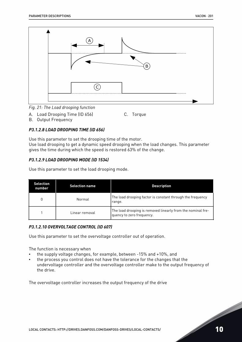
A
B
C
Fig. 21: The Load drooping functionA. Load Drooping Time (ID 656)B. Output Frequency
C. Torque
P3.1.2.8 LOAD DROOPING TIME (ID 656)
Use this parameter to set the drooping time of the motor.Use load drooping to get a dynamic speed drooping when the load changes. This parametergives the time during which the speed is restored 63% of the change.
P3.1.2.9 LOAD DROOPING MODE (ID 1534)
Use this parameter to set the load drooping mode.
Selectionnumber Selection name Description
0 Normal The load drooping factor is constant through the frequencyrange.
1 Linear removal The load drooping is removed linearly from the nominal fre-quency to zero frequency.
P3.1.2.10 OVERVOLTAGE CONTROL (ID 607)
Use this parameter to set the overvoltage controller out of operation.
The function is necessary when• the supply voltage changes, for example, between -15% and +10%, and• the process you control does not have the tolerance for the changes that the
undervoltage controller and the overvoltage controller make to the output frequency ofthe drive.
The overvoltage controller increases the output frequency of the drive
PARAMETER DESCRIPTIONS VACON · 201
LOCAL CONTACTS: HTTP://DRIVES.DANFOSS.COM/DANFOSS-DRIVES/LOCAL-CONTACTS/ 10
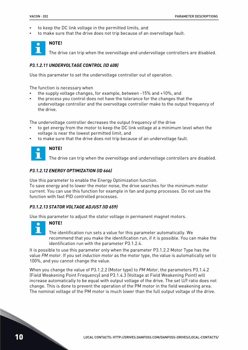
• to keep the DC link voltage in the permitted limits, and• to make sure that the drive does not trip because of an overvoltage fault.
NOTE!
The drive can trip when the overvoltage and undervoltage controllers are disabled.
P3.1.2.11 UNDERVOLTAGE CONTROL (ID 608)
Use this parameter to set the undervoltage controller out of operation.
The function is necessary when• the supply voltage changes, for example, between -15% and +10%, and• the process you control does not have the tolerance for the changes that the
undervoltage controller and the overvoltage controller make to the output frequency ofthe drive.
The undervoltage controller decreases the output frequency of the drive• to get energy from the motor to keep the DC link voltage at a minimum level when the
voltage is near the lowest permitted limit, and• to make sure that the drive does not trip because of an undervoltage fault.
NOTE!
The drive can trip when the overvoltage and undervoltage controllers are disabled.
P3.1.2.12 ENERGY OPTIMIZATION (ID 666)
Use this parameter to enable the Energy Optimization function.To save energy and to lower the motor noise, the drive searches for the minimum motorcurrent. You can use this function for example in fan and pump processes. Do not use thefunction with fast PID controlled processes.
P3.1.2.13 STATOR VOLTAGE ADJUST (ID 659)
Use this parameter to adjust the stator voltage in permanent magnet motors.NOTE!
The identification run sets a value for this parameter automatically. Werecommend that you make the identification run, if it is possible. You can make theidentification run with the parameter P3.1.2.4.
It is possible to use this parameter only when the parameter P3.1.2.2 Motor Type has thevalue PM motor. If you set induction motor as the motor type, the value is automatically set to100%, and you cannot change the value.
When you change the value of P3.1.2.2 (Motor type) to PM Motor, the parameters P3.1.4.2(Field Weakening Point Frequency) and P3.1.4.3 (Voltage at Field Weakening Point) willincrease automatically to be equal with output voltage of the drive. The set U/f ratio does notchange. This is done to prevent the operation of the PM motor in the field weakening area.The nominal voltage of the PM motor is much lower than the full output voltage of the drive.
VACON · 202 PARAMETER DESCRIPTIONS
10 LOCAL CONTACTS: HTTP://DRIVES.DANFOSS.COM/DANFOSS-DRIVES/LOCAL-CONTACTS/
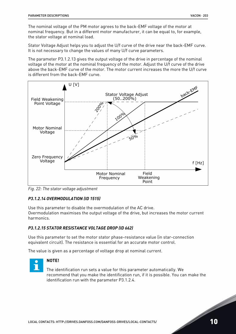
The nominal voltage of the PM motor agrees to the back-EMF voltage of the motor atnominal frequency. But in a different motor manufacturer, it can be equal to, for example,the stator voltage at nominal load.
Stator Voltage Adjust helps you to adjust the U/f curve of the drive near the back-EMF curve.It is not necessary to change the values of many U/f curve parameters.
The parameter P3.1.2.13 gives the output voltage of the drive in percentage of the nominalvoltage of the motor at the nominal frequency of the motor. Adjust the U/f curve of the driveabove the back-EMF curve of the motor. The motor current increases the more the U/f curveis different from the back-EMF curve.
FieldWeakening
Point
Field WeakeningPoint Voltage
Motor NominalVoltage
Motor NominalFrequency
Stator Voltage Adjust back-EMF
Zero FrequencyVoltage
(50..200%)20
0%
100%
50%
f [Hz]
U [V]
Fig. 22: The stator voltage adjustment
P3.1.2.14 OVERMODULATION (ID 1515)
Use this parameter to disable the overmodulation of the AC drive.Overmodulation maximises the output voltage of the drive, but increases the motor currentharmonics.
P3.1.2.15 STATOR RESISTANCE VOLTAGE DROP (ID 662)
Use this parameter to set the motor stator phase-resistance value (in star-connectionequivalent circuit). The resistance is essential for an accurate motor control.
The value is given as a percentage of voltage drop at nominal current.
NOTE!
The identification run sets a value for this parameter automatically. Werecommend that you make the identification run, if it is possible. You can make theidentification run with the parameter P3.1.2.4.
PARAMETER DESCRIPTIONS VACON · 203
LOCAL CONTACTS: HTTP://DRIVES.DANFOSS.COM/DANFOSS-DRIVES/LOCAL-CONTACTS/ 10
P3.1.2.16 STATOR INDUCTANCE VOLTAGE DROP (ID 673)
Use this parameter to set the motor stator phase-inductance value (in star-connectionequivalent circuit). The value is the transient inductance (for induction motors) or the line-to-neutral inductance (for permanent magnet and reluctance motors).
The value is given as a percentage of voltage drop at nominal current and nominal frequency.
NOTE!
The identification run sets a value for this parameter automatically. Werecommend that you make the identification run, if it is possible. You can make theidentification run with the parameter P3.1.2.4.
P3.1.2.17 MOTOR BEM VOLTAGE (ID 674)
Use this parameter to set the back electromotive force (back-EMF) voltage of a permanentmagnet motor. The value of this parameter is the motor terminal voltage when the motorcurrent is zero.
The value is given as line-to-line RMS voltage at nominal operating frequency. Identificationat standstill uses this parameter to set U/f curve in open loop control mode. The back-EMFvalue that is identified in Identification with rotation overwrites the existing parameter value.
10.2.3 MOTOR LIMITS
P3.1.3.1 MOTOR CURRENT LIMIT (ID 107)
Use this parameter to set the maximum motor current from the AC drive.The range of values for the parameter is different for each enclosure size of the drive.
When the current limit is active, the drive output frequency decreases.
NOTE!
The Motor Current Limit is not an overcurrent trip limit.
P3.1.3.2 MOTOR TORQUE LIMIT (ID 1287)
Use this parameter to set the maximum torque limit of the motoring side.The range of values for the parameter is different for each enclosure size of the drive.
P3.1.3.3 GENERATOR TORQUE LIMIT (ID 1288)
Use this parameter to set the maximum torque limit of the generating side.The range of values for the parameter is different for each enclosure size of the drive.
P3.1.3.4 MOTOR POWER LIMIT (ID 1289)
Use this parameter to set the maximum power limit of the motoring side.The range of values for the parameter is different for each enclosure size of the drive.
VACON · 204 PARAMETER DESCRIPTIONS
10 LOCAL CONTACTS: HTTP://DRIVES.DANFOSS.COM/DANFOSS-DRIVES/LOCAL-CONTACTS/
P3.1.3.5 GENERATOR POWER LIMIT (ID 1290)
Use this parameter to set the maximum power limit of the generating side.The range of values for the parameter is different for each enclosure size of the drive.
10.2.4 OPEN LOOP PARAMETERS
P3.1.4.1 U/F RATIO (ID 108)
Use this parameter to set the type of the U/f curve between zero frequency and the fieldweakening point.
Selectionnumber Selection name Description
0 Linear
The voltage of the motor changes linearly as a function of theoutput frequency. The voltage changes from the value ofP3.1.4.6 (Zero Frequency Voltage) to the value of P3.1.4.3(Voltage at Field Weakening Point) at a frequency set inP3.1.4.2 (Field Weakening Point Frequency). Use this defaultsetting if a different setting is not necessary.
1 Squared
The voltage of the motor changes from the value of P3.1.4.6(Zero Frequency Voltage) to the value of P3.1.4.2 (FieldWeakening Point Frequency) at a squared curve. The motoroperates undermagnetised below the field weakening pointand produces less torque. You can use the squared U/f ratioin applications where the torque demand is in relation to thesquare of the speed, for example in centrifugal fans andpumps.
2 Programmable
It is possible to program the U/f curve with 3 different points:the zero frequency voltage (P1), the midpoint voltage/frequency (P2), and the field weakening point (P3). You canuse the programmable U/f curve at low frequencies if it isnecessary to have more torque. You can find the optimal set-tings automatically with an identification run (P3.1.2.4).
PARAMETER DESCRIPTIONS VACON · 205
LOCAL CONTACTS: HTTP://DRIVES.DANFOSS.COM/DANFOSS-DRIVES/LOCAL-CONTACTS/ 10
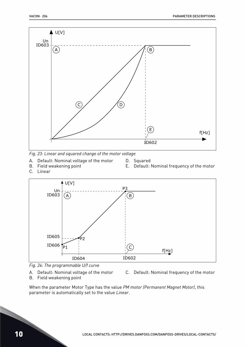
C
B
E
D
A
Un
U[V]
f[Hz]
ID603
ID602
Fig. 23: Linear and squared change of the motor voltageA. Default: Nominal voltage of the motorB. Field weakening pointC. Linear
D. SquaredE. Default: Nominal frequency of the motor
C
BA
P1
P2
P3
ID604
ID605
ID606
UnID603
ID602
U[V]
f[Hz]
Fig. 24: The programmable U/f curveA. Default: Nominal voltage of the motorB. Field weakening point
C. Default: Nominal frequency of the motor
When the parameter Motor Type has the value PM motor (Permanent Magnet Motor), thisparameter is automatically set to the value Linear.
VACON · 206 PARAMETER DESCRIPTIONS
10 LOCAL CONTACTS: HTTP://DRIVES.DANFOSS.COM/DANFOSS-DRIVES/LOCAL-CONTACTS/
When the parameter Motor Type has the value Induction Motor, and when this parameter ischanged, these parameters are set to their default values.• P3.1.4.2 Field Weakening Point Frequency• P3.1.4.3 Voltage at Field Weakening Point• P3.1.4.4 U/f Midpoint Frequency• P3.1.4.5 U/f Midpoint Voltage• P3.1.4.6 Zero Frequency Voltage
P3.1.4.2 FIELD WEAKENING POINT FREQUENCY (ID 602)
Use this parameter to set the output frequency at which the output voltage reaches the fieldweakening point voltage.
P3.1.4.3 VOLTAGE AT FIELD WEAKENING POINT (ID 603)
Use this parameter to set the voltage at the field weakening point as a percentage of themotor nominal voltage.Above the frequency at the field weakening point, the output voltage stays at the setmaximum value. Below the frequency at the field weakening point, the U/f curve parameterscontrol the output voltage. See the U/f parameters P3.1.4.1, P3.1.4.4 and P3.1.4.5.
When you set the parameters P3.1.1.1 (Motor nominal voltage) and P3.1.1.2 (Motor nominalfrequency), the parameters P3.1.4.2 and P3.1.4.3 automatically receive related values. Tohave different values for P3.1.4.2 and P3.1.4.3, change these parameters only after you setthe parameters P3.1.1.1 and P3.1.1.2.
P3.1.4.4 U/F MIDPOINT FREQUENCY (ID 604)
Use this parameter to set the middle point frequency of the U/f curve.
NOTE!
This parameter gives the middle point frequency of the curve if the value of P3.1.4.1is programmable.
P3.1.4.5 U/F MIDPOINT VOLTAGE (ID 605)
Use this parameter to set the middle point voltage of the U/f curve.
NOTE!
This parameter gives the middle point voltage of the curve if the value of P3.1.4.1 isprogrammable.
P3.1.4.6 ZERO FREQUENCY VOLTAGE (ID 606)
Use this parameter to set the zero frequency voltage of the U/f curve.The default value for the parameter is different for each unit size.
P3.1.4.7 FLYING START OPTIONS (ID 1590)
Use this parameter to set the flying start options.The parameter Flying Start Options has a checkbox selection of values.
PARAMETER DESCRIPTIONS VACON · 207
LOCAL CONTACTS: HTTP://DRIVES.DANFOSS.COM/DANFOSS-DRIVES/LOCAL-CONTACTS/ 10
The bits can receive these values.• Search the shaft frequency only from the same direction as the frequency reference• Disable the AC scanning• Use the frequency reference for an initial guess• Disable the DC pulses• Flux build with current control
The bit B0 controls the search direction. When you set the bit to 0, the shaft frequency issearched in 2 directions, the positive and the negative. When you set the bit to 1, the shaftfrequency is searched only in the frequency reference direction. This prevents the shaftmovements for the other direction.
The bit B1 controls the AC scanning that premagnetises the motor. In the AC scanning, thesystem sweeps the frequency from the maximum towards zero frequency. The AC scanningstops when an adaptation to the shaft frequency occurs. To disable the AC scanning, set thebit B1 to 1. If the value of Motor Type is permanent magnet motor, the AC scanning isdisabled automatically.
With the bit B5 you can disable the DC pulses. The primary function of the DC pulses is topremagnetise the motor and examine the rotation of the motor. If the DC pulses and the ACscanning are enabled, the slip frequency tells which procedure is applied. If the slipfrequency is less than 2 Hz, or the motor type is PM motor, the DC pulses are disabledautomatically.
The bit B7 controls the rotation direction of the injected high frequency signal, which is usedin the flying start of synchronous reluctance machines. Signal injection is used to detect thefrequency of the rotor. If the rotor is in a blind angle when the signal is injected, the rotorfrequency is undetectable. Reversing the rotation direction of the injection signal solves thisproblem.
P3.1.4.8 FLYING START SCAN CURRENT (ID 1610)
Use this parameter to set the flying start scan current as a percentage of the motor nominalcurrent.
P3.1.4.9 AUTOMATIC TORQUE BOOST (ID 109)
Use this parameter with a process that has a high starting torque because of friction.
The voltage to the motor changes in relation to the necessary torque. This makes the motorgive more torque at the start and when the motor operates at low frequencies.
The torque boost has an effect with a linear U/f curve. You can get the best result when youhave done the identification run and activated the programmable U/f curve.
P3.1.4.10 TORQUE BOOST MOTOR GAIN (ID 667)
Use this parameter to set the scaling factor for the motoring side IR-compensation when thetorque boost is used.
P3.1.4.11 TORQUE BOOST GENERATOR GAIN (ID 665)
Use this parameter to set the scaling factor for the generating side IR-compensation whenthe torque boost is used.
VACON · 208 PARAMETER DESCRIPTIONS
10 LOCAL CONTACTS: HTTP://DRIVES.DANFOSS.COM/DANFOSS-DRIVES/LOCAL-CONTACTS/
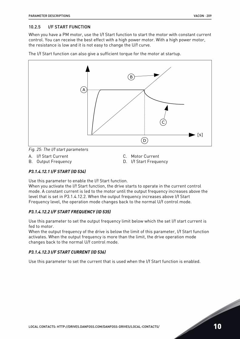
10.2.5 I/F START FUNCTIONWhen you have a PM motor, use the I/f Start function to start the motor with constant currentcontrol. You can receive the best effect with a high power motor. With a high power motor,the resistance is low and it is not easy to change the U/f curve.
The I/f Start function can also give a sufficient torque for the motor at startup.
C
B
D
A
[s]
Fig. 25: The I/f start parametersA. I/f Start CurrentB. Output Frequency
C. Motor CurrentD. I/f Start Frequency
P3.1.4.12.1 I/F START (ID 534)
Use this parameter to enable the I/f Start function.When you activate the I/f Start function, the drive starts to operate in the current controlmode. A constant current is led to the motor until the output frequency increases above thelevel that is set in P3.1.4.12.2. When the output frequency increases above I/f StartFrequency level, the operation mode changes back to the normal U/f control mode.
P3.1.4.12.2 I/F START FREQUENCY (ID 535)
Use this parameter to set the output frequency limit below which the set I/f start current isfed to motor.When the output frequency of the drive is below the limit of this parameter, I/f Start functionactivates. When the output frequency is more than the limit, the drive operation modechanges back to the normal U/f control mode.
P3.1.4.12.3 I/F START CURRENT (ID 536)
Use this parameter to set the current that is used when the I/f Start function is enabled.
PARAMETER DESCRIPTIONS VACON · 209
LOCAL CONTACTS: HTTP://DRIVES.DANFOSS.COM/DANFOSS-DRIVES/LOCAL-CONTACTS/ 10
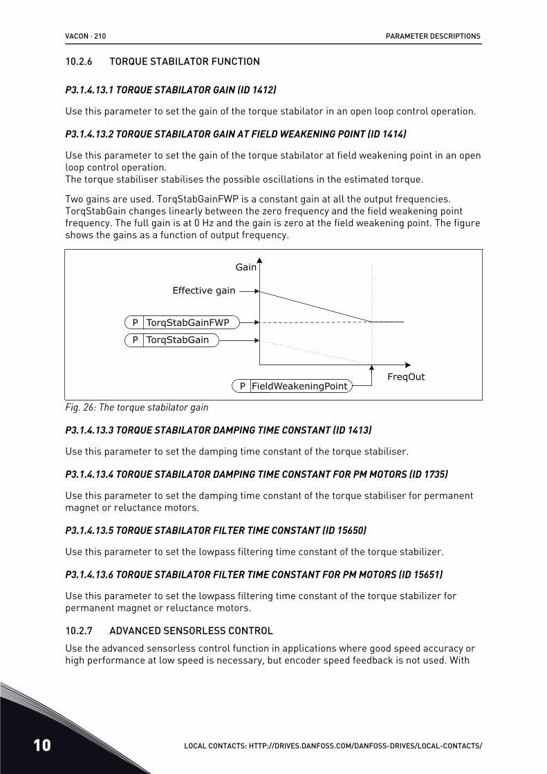
10.2.6 TORQUE STABILATOR FUNCTION
P3.1.4.13.1 TORQUE STABILATOR GAIN (ID 1412)
Use this parameter to set the gain of the torque stabilator in an open loop control operation.
P3.1.4.13.2 TORQUE STABILATOR GAIN AT FIELD WEAKENING POINT (ID 1414)
Use this parameter to set the gain of the torque stabilator at field weakening point in an openloop control operation.The torque stabiliser stabilises the possible oscillations in the estimated torque.
Two gains are used. TorqStabGainFWP is a constant gain at all the output frequencies.TorqStabGain changes linearly between the zero frequency and the field weakening pointfrequency. The full gain is at 0 Hz and the gain is zero at the field weakening point. The figureshows the gains as a function of output frequency.
P FieldWeakeningPoint
P TorqStabGainFWP
Effective gain
FreqOut
Gain
P TorqStabGain
Fig. 26: The torque stabilator gain
P3.1.4.13.3 TORQUE STABILATOR DAMPING TIME CONSTANT (ID 1413)
Use this parameter to set the damping time constant of the torque stabiliser.
P3.1.4.13.4 TORQUE STABILATOR DAMPING TIME CONSTANT FOR PM MOTORS (ID 1735)
Use this parameter to set the damping time constant of the torque stabiliser for permanentmagnet or reluctance motors.
P3.1.4.13.5 TORQUE STABILATOR FILTER TIME CONSTANT (ID 15650)
Use this parameter to set the lowpass filtering time constant of the torque stabilizer.
P3.1.4.13.6 TORQUE STABILATOR FILTER TIME CONSTANT FOR PM MOTORS (ID 15651)
Use this parameter to set the lowpass filtering time constant of the torque stabilizer forpermanent magnet or reluctance motors.
10.2.7 ADVANCED SENSORLESS CONTROLUse the advanced sensorless control function in applications where good speed accuracy orhigh performance at low speed is necessary, but encoder speed feedback is not used. With
VACON · 210 PARAMETER DESCRIPTIONS
10 LOCAL CONTACTS: HTTP://DRIVES.DANFOSS.COM/DANFOSS-DRIVES/LOCAL-CONTACTS/
the advanced sensorless control, a simple closed loop motor control can be replaced with ahigh-performance open loop motor control. An example of a possible application is anextruder.
The advanced sensorless control function is not supported when a sine filter or a harmonicfilter is used.
This control mode is sensitive about accurate motor parameterisation and requires expertknowledge in the commissioning. We strongly recommend you NOT to enable this mode forregular open loop motor control applications or when expert knowledge is not available.
The advanced sensorless control has a similar control structure to the closed loop controlbut with voltage vector control. The selection between frequency, speed and torque control isstill done with P3.1.2.1 Control Mode.
When you are commissioning the sensorless control function, always do these steps:
• Do identification with rotation (P1.15/P3.1.2.4 = 2).• Set reasonable minimum frequencies (P3.3.1.1-3.3.1.4).• Use motor stall protection (P3.9.3.1-3.9.3.4).
With an induction motor, always use start magnetisation to build up rotor flux. With a PMmotor, using start magnetisation is highly recommended to make sure that the rotoralignment is correct.
The identification with rotation is necessary because the advanced sensorless control issensitive about accurate motor parameterisation. We recommend you to use minimumfrequencies because continuous operation at or near zero frequency can cause instability ofcontrol and should be prevented. The motor stall protection function protects the motor incase of instability at low frequency that can cause continuous high current that increases themotor temperature.
In the speed control mode with an IM motor, especially the generator side must be taken intoaccount because the flux frequency is smaller than the shaft frequency because of the slipfrequency.
NOTE!
The characteristics of the application have an effect on the optimal settings of thecontrol mode parameters.
P3.1.6.1 SENSORLESS CONTROL (ID 1724)
Use this parameter to enable the sensorless control function.
P3.1.6.3 SENSORLESS CONTROL OPTIONS (ID 1726)
Use this parameter to set the options of the advanced sensorless control. The parameter hasa checkbox selection of values.
PARAMETER DESCRIPTIONS VACON · 211
LOCAL CONTACTS: HTTP://DRIVES.DANFOSS.COM/DANFOSS-DRIVES/LOCAL-CONTACTS/ 10
Selectionnumber Selection name Description
B0 Stator resistance identification Identify the stator resistance during the start magnetisation.
B3 Limit frequency polarity
B6 Enable IR-compensation adjust
B8 Voltage based current limit
B14 Ramp anti-windup Use the ramp anti-windup control.
The bit B0 enables stator resistance identification at each start. It cannot be used when astart is made to a rotating motor. It is recommended when a start is always made fromstandstill.
The temperature has an effect on the stator resistance value. A correct resistance value isnecessary for the advanced sensorless control, especially at low frequencies. Thetemperature effect is mitigated, when instead of using a value that was identified in the firstidentification run, the resistance is identified at each start.
When you set the bit to 1, the stator resistance is identified during the start magnetisation.For this to happen, enable the start magnetisation function with P3.4.3.1 Start MagnetisingCurrent and P3.4.3.2 Start Magnetising Time. For induction motors, start magnetising isenabled already when the identification run is made.
Bit B3 can be used to improve the robustness in applications that require high torque at lowspeeds but that do not require speed reversals with full load and also do not operate withsubstantial load on the generator side at low frequencies. An example of a suitableapplication is an extruder.
When you select bit B3, the sign (+ or -) of the output frequency is limited according to thesign of the user frequency reference. When positive frequency reference is used, the outputfrequency is limited to positive values. When negative frequency reference is used, onlynegative output frequency is allowed. As a result, the operation is limited in an area whereany parameter fault has the most significant effect. This improves the robustness of thecontrol.
Bit B6 is targeted to enable robustness improvement in applications that do not require hightorque at low frequencies.
When bit B6 is activated, you can adjust the IR compensation in the same way as in a normalopen loop control using parameter P3.1.4.10 Torque Boost Motor Gain. When the gain valueis reduced, sensitivity against parameter faults is also reduced and robustness is improved.Reducing the gain value also reduces torque capability at low frequencies.
Bit B8 activates a function that reduces the risk of the control system getting stuck in thecurrent limit at low frequencies by limiting the motor voltage. This could occur because oferrors in the parameter settings. The function is active only when the output frequency isless than 1.0 Hz.
Use the bit B8 only if the nature of the process allows it, because otherwise it can lead to lossof performance due to limited voltage. Bit B8 can be used if there is no need to run against
VACON · 212 PARAMETER DESCRIPTIONS
10 LOCAL CONTACTS: HTTP://DRIVES.DANFOSS.COM/DANFOSS-DRIVES/LOCAL-CONTACTS/
current or torque limit or handle high loads at low frequencies in normal operation. Anexample of a situation when the bit should not be used is operation against a locked rotor.
The bit B14 defines the reaction of the ramp output during the limit control functions. Bydefault, the limit controls have no effect on the ramp output. This causes the motor toaccelerate with maximum torque (against the current limit) to the speed reference when thelimit control deactivates.
By activating bit B14, the ramp output follows the actual frequency/speed with a defined gap.Thus, when the limit control deactivates, the motor accelerates to the speed reference withthe defined ramp time. The default value of the gap frequency is 3.0 Hz.
P3.1.6.8 SPEED CONTROL GAIN (ID 1733)
The speed controller is always active in advanced sensorless control. Depending on thedesired response and the total inertia, it is possible that the speed controller requires sometuning.
P3.1.6.9 SPEED CONTROL TIME (ID 1734)
The speed controller is always active in advanced sensorless control. Depending on thedesired response and the total inertia, it is possible that the speed controller requires sometuning.
P3.1.6.14 FLUX REFERENCE
Use this parameter to adjust the flux reference. The value 100% means a nominal flux.
10.3 START/STOP SETUP
You must give the start and stop commands differently in each control place.
REMOTE CONTROL PLACE (I/O A)
Use the parameters P3.5.1.1 (Control signal 1 A), P3.5.1.2 (Control signal 2 A) and P3.5.1.3(Control signal 3 A) to make a selection of digital inputs. These digital inputs control thestart, stop and reverse commands. Then make a selection of a logic for these inputs withP3.2.6 I/O A Logic.
REMOTE CONTROL PLACE (I/O B)
Use the parameters P3.5.1.4 (Control signal 1 B), P3.5.1.5 (Control signal 2 B) and P3.5.1.6(Control signal 3 B) to make a selection of digital inputs. These digital inputs control thestart, stop and reverse commands. Then make a selection of a logic for these inputs withP3.2.7 I/O B Logic.
LOCAL CONTROL PLACE (KEYPAD)
The start and stop commands come from the keypad buttons. The direction of the rotation isset with parameter P3.3.1.9 Keypad direction.
REMOTE CONTROL PLACE (FIELDBUS)
Start, stop and reverse commands come from the fieldbus.
PARAMETER DESCRIPTIONS VACON · 213
LOCAL CONTACTS: HTTP://DRIVES.DANFOSS.COM/DANFOSS-DRIVES/LOCAL-CONTACTS/ 10
P3.2.1 REMOTE CONTROL PLACE (ID 172)
Use this parameter to select the remote control place (start/stop).Use this parameter to change back to remote control from VACON® Live, for example if thecontrol panel is broken.
P3.2.2 LOCAL/REMOTE (ID 211)
Use this parameter to switch between the local and remote control places.Local control place is always keypad control. The remote control place can be I/O orFieldbus, depending on the 'Remote Control Place' parameter value.
P3.2.3 KEYPAD STOP BUTTON (ID 114)
Use this parameter to enable the keypad stop button.When this function is enabled, a press of keypad stop button always stops the drive(regardless of the control place). When this function is disabled, a press of keypad stopbutton stops the drive in local control only.
Selectionnumber Selection name Description
0 Yes The keypad stop button is always enabled.
1 No Limited function of the keypad stop button.
P3.2.4 START FUNCTION (ID 505)
Use this parameter to select the type of the start function.
Selectionnumber Selection name Description
0 Ramping The drive accelerates from 0 frequency to frequency refer-ence.
1 Flying start The drive detects the actual speed of the motor and acceler-ates from that speed to frequency reference.
P3.2.5 STOP FUNCTION (ID 506)
Use this parameter to select the type of the stop function.
Selectionnumber Selection name Description
0 CoastingThe motor stops on its inertia. When the stop command isgiven, the control by the drive stops and the current from thedrive goes to 0.
1 Ramp After the stop command, the speed of the motor is decreasedto zero speed according to the deceleration parameters.
VACON · 214 PARAMETER DESCRIPTIONS
10 LOCAL CONTACTS: HTTP://DRIVES.DANFOSS.COM/DANFOSS-DRIVES/LOCAL-CONTACTS/
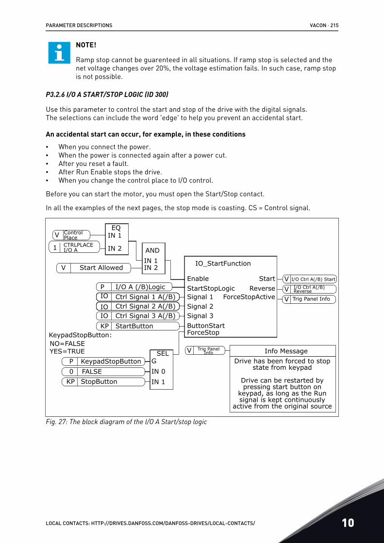
NOTE!
Ramp stop cannot be guarenteed in all situations. If ramp stop is selected and thenet voltage changes over 20%, the voltage estimation fails. In such case, ramp stopis not possible.
P3.2.6 I/O A START/STOP LOGIC (ID 300)
Use this parameter to control the start and stop of the drive with the digital signals.The selections can include the word 'edge' to help you prevent an accidental start.
An accidental start can occur, for example, in these conditions
• When you connect the power.• When the power is connected again after a power cut.• After you reset a fault.• After Run Enable stops the drive.• When you change the control place to I/O control.
Before you can start the motor, you must open the Start/Stop contact.
In all the examples of the next pages, the stop mode is coasting. CS = Control signal.
Info Message
IO
IOP
P
IO
SELGIN 0IN 1
KP
VEQ
IN 1
IN 2 ANDIN 1IN 2V
NO=FALSEYES=TRUE
IO_StartFunction
Ctrl Signal 1 A(/B)Ctrl Signal 2 A(/B)
I/O A (/B)Logic
KeypadStopButton
StopButtonFALSE
StartStopLogicSignal 1
ForceStop
Signal 2
ButtonStartSignal 3
StartEnableReverse
ForceStopActive
StartButtonKeypadStopButton:
Ctrl Signal 3 A(/B)
Control PlaceCTRLPLACE I/O A
Start Allowed
1
0KP
V I/O Ctrl A(/B) Start
Trig Panel Info
I/O Ctrl A(/B) ReverseV
V
Trig Panel InfoV
Drive has been forced to stop state from keypad
Drive can be restarted by pressing start button on
keypad, as long as the Run signal is kept continuously
active from the original source
Fig. 27: The block diagram of the I/O A Start/stop logic
PARAMETER DESCRIPTIONS VACON · 215
LOCAL CONTACTS: HTTP://DRIVES.DANFOSS.COM/DANFOSS-DRIVES/LOCAL-CONTACTS/ 10
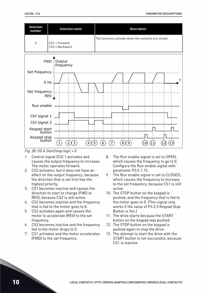
Selectionnumber Selection name Description
0 CS1 = ForwardCS2 = Backward
The functions activate when the contacts are closed.
t
Outputfrequency
FWD
REV
Ctrl signal 2
Ctrl signal 1
Run enable
Set frequency
Set frequency
0 Hz
Keypad stopbutton
Keypad startbutton
1 2 3 4 5 6 7 8 9 10 11 12 13
Fig. 28: I/O A Start/stop logic = 01. Control signal (CS) 1 activates and
causes the output frequency to increase.The motor operates forward.
2. CS2 activates, but it does not have aneffect on the output frequency, becausethe direction that is set first has thehighest priority.
3. CS1 becomes inactive and causes thedirection to start to change (FWD toREV), because CS2 is still active.
4. CS2 becomes inactive and the frequencythat is fed to the motor goes to 0.
5. CS2 activates again and causes themotor to accelerate (REV) to the setfrequency.
6. CS2 becomes inactive and the frequencyfed to the motor drops to 0.
7. CS1 activates and the motor accelerates(FWD) to the set frequency
8. The Run enable signal is set to OPEN,which causes the frequency to go to 0.Configure the Run enable signal withparameter P3.5.1.15.
9. The Run enable signal is set to CLOSED,which causes the frequency to increaseto the set frequency, because CS1 is stillactive.
10. The STOP button on the keypad ispushed, and the frequency that is fed tothe motor goes to 0. (This signal onlyworks if the value of P3.2.3 Keypad StopButton is Yes.)
11. The drive starts because the STARTbutton on the keypad was pushed.
12. The STOP button on the keypad ispushed again to stop the drive.
13. The attempt to start the drive with theSTART button is not successful, becauseCS1 is inactive.
VACON · 216 PARAMETER DESCRIPTIONS
10 LOCAL CONTACTS: HTTP://DRIVES.DANFOSS.COM/DANFOSS-DRIVES/LOCAL-CONTACTS/
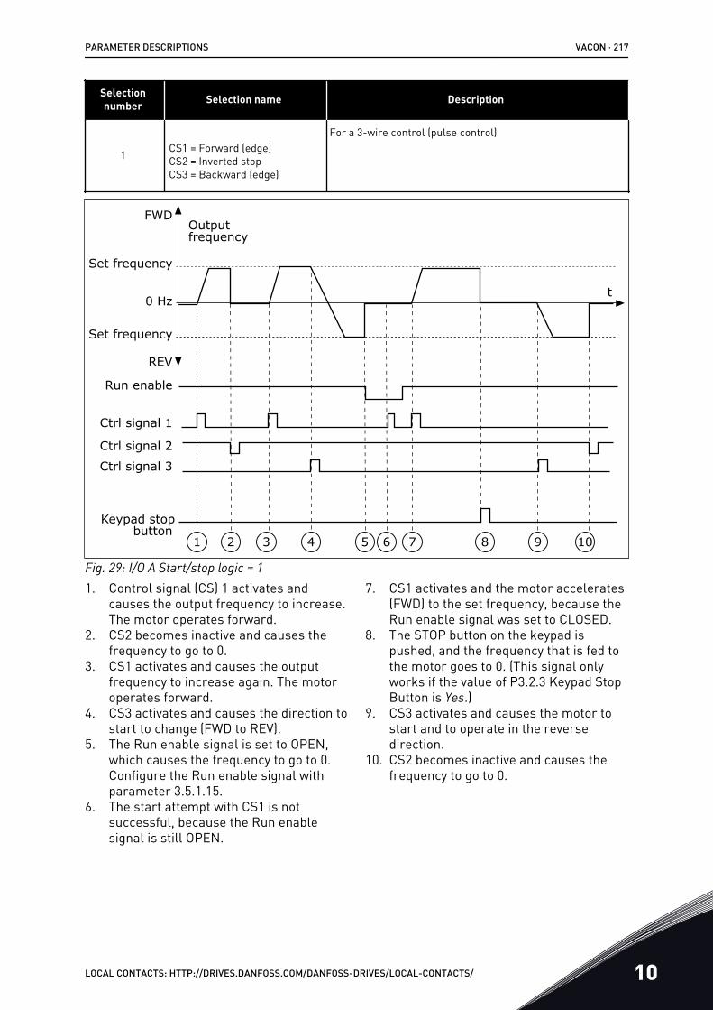
Selectionnumber Selection name Description
1 CS1 = Forward (edge)CS2 = Inverted stopCS3 = Backward (edge)
For a 3-wire control (pulse control)
Set frequency
0 Hz
Keypad stopbutton
Ctrl signal 3
t
Outputfrequency
FWD
REV
Ctrl signal 2
Ctrl signal 1
Run enable
Set frequency
1 2 3 4 5 6 7 98 10
Fig. 29: I/O A Start/stop logic = 11. Control signal (CS) 1 activates and
causes the output frequency to increase.The motor operates forward.
2. CS2 becomes inactive and causes thefrequency to go to 0.
3. CS1 activates and causes the outputfrequency to increase again. The motoroperates forward.
4. CS3 activates and causes the direction tostart to change (FWD to REV).
5. The Run enable signal is set to OPEN,which causes the frequency to go to 0.Configure the Run enable signal withparameter 3.5.1.15.
6. The start attempt with CS1 is notsuccessful, because the Run enablesignal is still OPEN.
7. CS1 activates and the motor accelerates(FWD) to the set frequency, because theRun enable signal was set to CLOSED.
8. The STOP button on the keypad ispushed, and the frequency that is fed tothe motor goes to 0. (This signal onlyworks if the value of P3.2.3 Keypad StopButton is Yes.)
9. CS3 activates and causes the motor tostart and to operate in the reversedirection.
10. CS2 becomes inactive and causes thefrequency to go to 0.
PARAMETER DESCRIPTIONS VACON · 217
LOCAL CONTACTS: HTTP://DRIVES.DANFOSS.COM/DANFOSS-DRIVES/LOCAL-CONTACTS/ 10
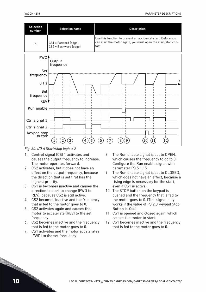
Selectionnumber Selection name Description
2 CS1 = Forward (edge)CS2 = Backward (edge)
Use this function to prevent an accidental start. Before youcan start the motor again, you must open the start/stop con-tact.
1 2 3 4 5 6 7 8 9 10 11 12
t
Outputfrequency
FWD
REV
Ctrl signal 2
Ctrl signal 1
Run enable
Set frequency
Set frequency
0 Hz
Keypad stop button
Fig. 30: I/O A Start/stop logic = 21. Control signal (CS) 1 activates and
causes the output frequency to increase.The motor operates forward.
2. CS2 activates, but it does not have aneffect on the output frequency, becausethe direction that is set first has thehighest priority.
3. CS1 is becomes inactive and causes thedirection to start to change (FWD toREV), because CS2 is still active.
4. CS2 becomes inactive and the frequencythat is fed to the motor goes to 0.
5. CS2 activates again and causes themotor to accelerate (REV) to the setfrequency.
6. CS2 becomes inactive and the frequencythat is fed to the motor goes to 0.
7. CS1 activates and the motor accelerates(FWD) to the set frequency.
8. The Run enable signal is set to OPEN,which causes the frequency to go to 0.Configure the Run enable signal withparameter P3.5.1.15.
9. The Run enable signal is set to CLOSED,which does not have an effect, because arising edge is necessary for the start,even if CS1 is active.
10. The STOP button on the keypad ispushed and the frequency that is fed tothe motor goes to 0. (This signal onlyworks if the value of P3.2.3 Keypad StopButton is Yes.)
11. CS1 is opened and closed again, whichcauses the motor to start.
12. CS1 becomes inactive and the frequencythat is fed to the motor goes to 0.
VACON · 218 PARAMETER DESCRIPTIONS
10 LOCAL CONTACTS: HTTP://DRIVES.DANFOSS.COM/DANFOSS-DRIVES/LOCAL-CONTACTS/
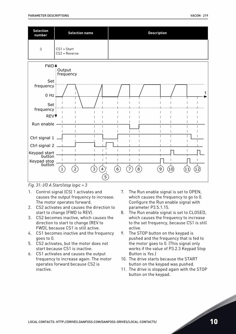
Selectionnumber Selection name Description
3 CS1 = StartCS2 = Reverse
1 2 3 4 6 7 8 9 10 11 12
5
t
Outputfrequency
FWD
REV
Ctrl signal 2
Ctrl signal 1
Run enable
Set frequency
Set frequency
0 Hz
Keypad stop button
Keypad start button
Fig. 31: I/O A Start/stop logic = 31. Control signal (CS) 1 activates and
causes the output frequency to increase.The motor operates forward.
2. CS2 activates and causes the direction tostart to change (FWD to REV).
3. CS2 becomes inactive, which causes thedirection to start to change (REV toFWD), because CS1 is still active.
4. CS1 becomes inactive and the frequencygoes to 0.
5. CS2 activates, but the motor does notstart because CS1 is inactive.
6. CS1 activates and causes the outputfrequency to increase again. The motoroperates forward because CS2 isinactive.
7. The Run enable signal is set to OPEN,which causes the frequency to go to 0.Configure the Run enable signal withparameter P3.5.1.15.
8. The Run enable signal is set to CLOSED,which causes the frequency to increaseto the set frequency, because CS1 is stillactive.
9. The STOP button on the keypad ispushed and the frequency that is fed tothe motor goes to 0. (This signal onlyworks if the value of P3.2.3 Keypad StopButton is Yes.)
10. The drive starts because the STARTbutton on the keypad was pushed.
11. The drive is stopped again with the STOPbutton on the keypad.
PARAMETER DESCRIPTIONS VACON · 219
LOCAL CONTACTS: HTTP://DRIVES.DANFOSS.COM/DANFOSS-DRIVES/LOCAL-CONTACTS/ 10
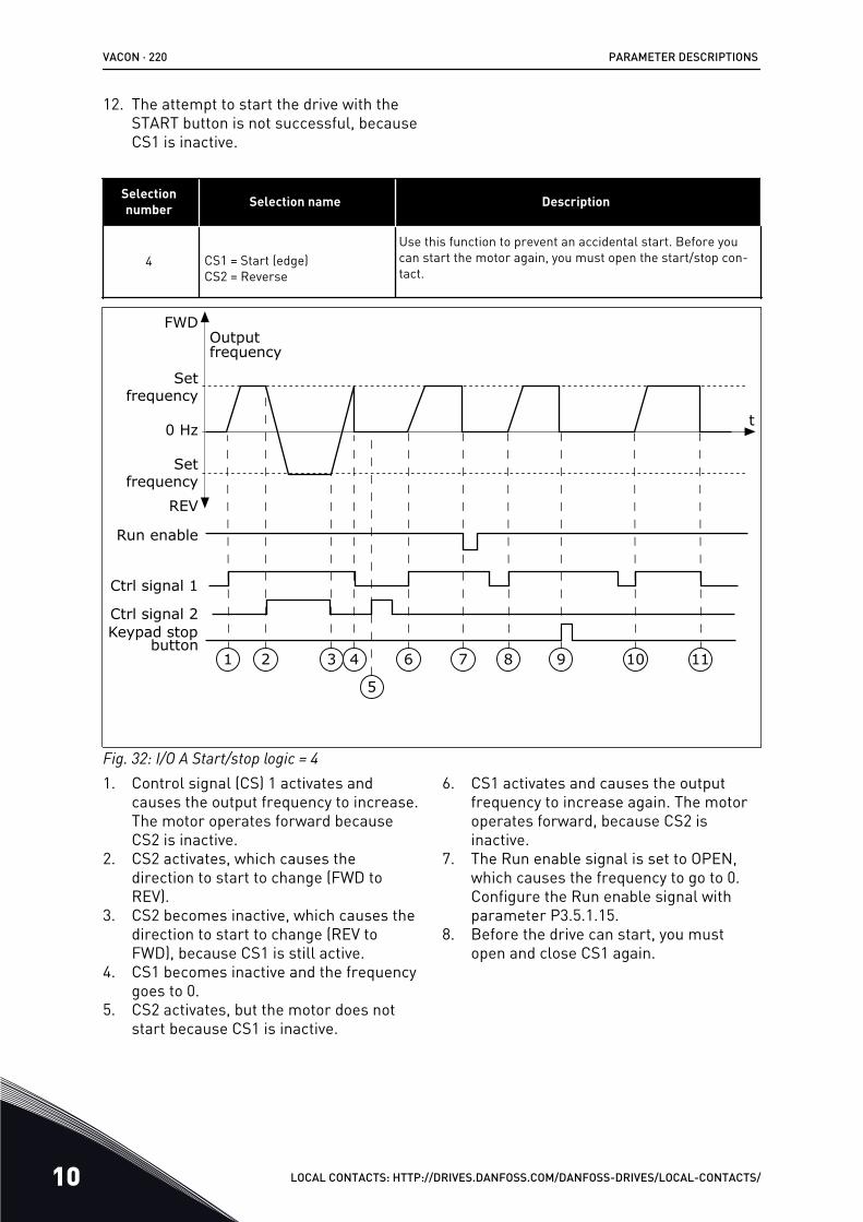
12. The attempt to start the drive with theSTART button is not successful, becauseCS1 is inactive.
Selectionnumber Selection name Description
4 CS1 = Start (edge)CS2 = Reverse
Use this function to prevent an accidental start. Before youcan start the motor again, you must open the start/stop con-tact.
1 2 3 4 6 7 8 9 10 11
5
t
Outputfrequency
FWD
REV
Ctrl signal 2
Ctrl signal 1
Run enable
Set frequency
Set frequency
0 Hz
Keypad stop button
Fig. 32: I/O A Start/stop logic = 41. Control signal (CS) 1 activates and
causes the output frequency to increase.The motor operates forward becauseCS2 is inactive.
2. CS2 activates, which causes thedirection to start to change (FWD toREV).
3. CS2 becomes inactive, which causes thedirection to start to change (REV toFWD), because CS1 is still active.
4. CS1 becomes inactive and the frequencygoes to 0.
5. CS2 activates, but the motor does notstart because CS1 is inactive.
6. CS1 activates and causes the outputfrequency to increase again. The motoroperates forward, because CS2 isinactive.
7. The Run enable signal is set to OPEN,which causes the frequency to go to 0.Configure the Run enable signal withparameter P3.5.1.15.
8. Before the drive can start, you mustopen and close CS1 again.
VACON · 220 PARAMETER DESCRIPTIONS
10 LOCAL CONTACTS: HTTP://DRIVES.DANFOSS.COM/DANFOSS-DRIVES/LOCAL-CONTACTS/
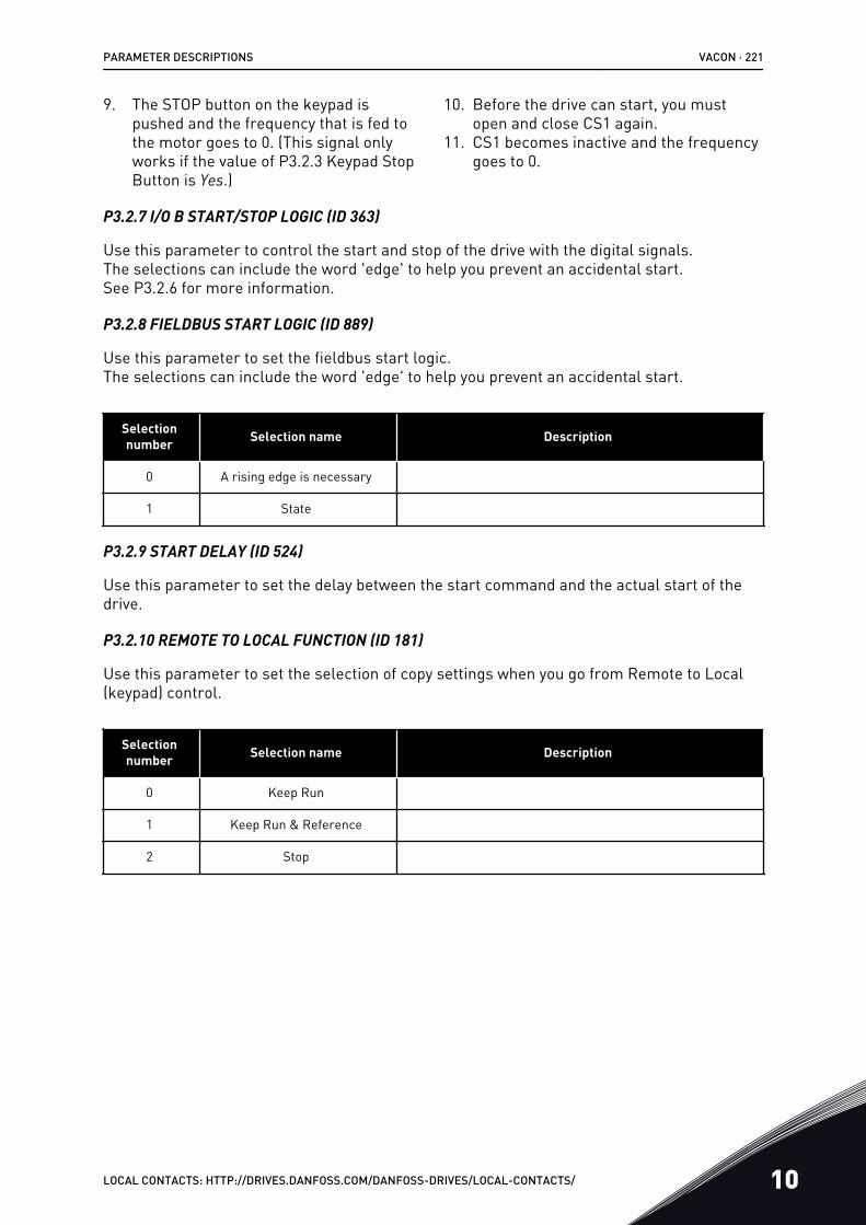
9. The STOP button on the keypad ispushed and the frequency that is fed tothe motor goes to 0. (This signal onlyworks if the value of P3.2.3 Keypad StopButton is Yes.)
10. Before the drive can start, you mustopen and close CS1 again.
11. CS1 becomes inactive and the frequencygoes to 0.
P3.2.7 I/O B START/STOP LOGIC (ID 363)
Use this parameter to control the start and stop of the drive with the digital signals.The selections can include the word 'edge' to help you prevent an accidental start.See P3.2.6 for more information.
P3.2.8 FIELDBUS START LOGIC (ID 889)
Use this parameter to set the fieldbus start logic.The selections can include the word 'edge' to help you prevent an accidental start.
Selectionnumber Selection name Description
0 A rising edge is necessary
1 State
P3.2.9 START DELAY (ID 524)
Use this parameter to set the delay between the start command and the actual start of thedrive.
P3.2.10 REMOTE TO LOCAL FUNCTION (ID 181)
Use this parameter to set the selection of copy settings when you go from Remote to Local(keypad) control.
Selectionnumber Selection name Description
0 Keep Run
1 Keep Run & Reference
2 Stop
PARAMETER DESCRIPTIONS VACON · 221
LOCAL CONTACTS: HTTP://DRIVES.DANFOSS.COM/DANFOSS-DRIVES/LOCAL-CONTACTS/ 10
10.4 REFERENCES
10.4.1 FREQUENCY REFERENCEIt is possible to program the source of the frequency reference in all the control places,except the PC tool. If you use your PC, it always takes the frequency reference from the PCtool.
REMOTE CONTROL PLACE (I/O A)
To set the source of the frequency reference for I/O A, use the parameter P3.3.1.5 .
REMOTE CONTROL PLACE (I/O B)
To set the source of the frequency reference for I/O B, use the parameter P3.3.1.6.
LOCAL CONTROL PLACE (KEYPAD)
If you use the default value keypad for the parameter P3.3.1.7, the reference that you set forP3.3.1.8 Keypad Reference applies.
REMOTE CONTROL PLACE (FIELDBUS)
If you keep the default value fieldbus for the parameter P3.3.1.10, the frequency referencecomes from fieldbus.
P3.3.1.1 MINIMUM FREQUENCY REFERENCE (ID 101)
Use this parameter to set the minimum frequency reference.
P3.3.1.2 MAXIMUM FREQUENCY REFERENCE (ID 102)
Use this parameter to set the maximum frequency reference.
P3.3.1.3 POSITIVE FREQUENCY REFERENCE LIMIT (ID 1285)
Use this parameter to set the final frequency reference limit for the positive direction.
P3.3.1.4 NEGATIVE FREQUENCY REFERENCE LIMIT (ID 1286)
Use this parameter to set the final frequency reference limit for the negative direction.Use this parameter for example to prevent the motor from running in the reverse direction.
P3.3.1.5 I/O CONTROL REFERENCE A SELECTION (ID 117)
Use this parameter to select the reference source when the control place is I/O A.The application that you set with parameter 1.2 gives the default value.
P3.3.1.6 I/O CONTROL REFERENCE B SELECTION (ID 131)
Use this parameter to select the reference source when the control place is I/O B.See P3.3.1.5 for more information. You can force the I/O B control place to be active only witha digital input (P3.5.1.7).
VACON · 222 PARAMETER DESCRIPTIONS
10 LOCAL CONTACTS: HTTP://DRIVES.DANFOSS.COM/DANFOSS-DRIVES/LOCAL-CONTACTS/
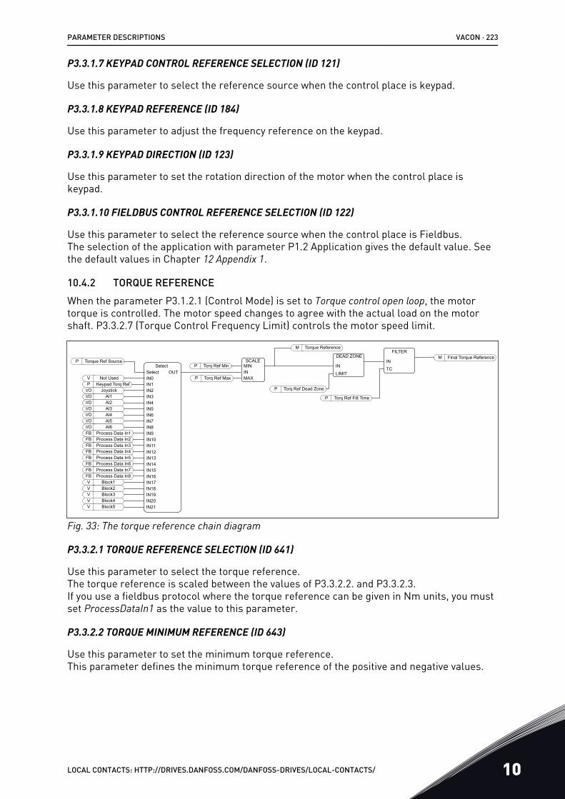
P3.3.1.7 KEYPAD CONTROL REFERENCE SELECTION (ID 121)
Use this parameter to select the reference source when the control place is keypad.
P3.3.1.8 KEYPAD REFERENCE (ID 184)
Use this parameter to adjust the frequency reference on the keypad.
P3.3.1.9 KEYPAD DIRECTION (ID 123)
Use this parameter to set the rotation direction of the motor when the control place iskeypad.
P3.3.1.10 FIELDBUS CONTROL REFERENCE SELECTION (ID 122)
Use this parameter to select the reference source when the control place is Fieldbus.The selection of the application with parameter P1.2 Application gives the default value. Seethe default values in Chapter 12 Appendix 1.
10.4.2 TORQUE REFERENCEWhen the parameter P3.1.2.1 (Control Mode) is set to Torque control open loop, the motortorque is controlled. The motor speed changes to agree with the actual load on the motorshaft. P3.3.2.7 (Torque Control Frequency Limit) controls the motor speed limit.
AIAIAIAIAIAI
123456
Process Data InProcess Data InProcess Data InProcess Data InProcess Data InProcess Data InProcess Data InProcess Data In
Not UsedKeypad Torq Ref
Joystick
SelectSelect
Torque Ref Source SCALETorq Ref Min
Torq Ref Max
Torq Ref Dead Zone
DEAD ZONEFILTER
Torq Ref Filt Time
Final Torque Reference
Torque ReferenceM
M
P
IN
TCIN
LIMIT
PMININMAX
P
P
P
I/OI/OI/OI/OI/OI/OFB 1FB 2FB 3FB 4FB 5FB 6FB 7FB 8V Block1V Block2V Block3V Block4V Block5
VP
I/O
IN0IN1IN2IN3IN4IN5IN6IN7IN8IN9IN10IN11IN12IN13IN14IN15IN16IN17IN18IN19IN20IN21
OUT
Fig. 33: The torque reference chain diagram
P3.3.2.1 TORQUE REFERENCE SELECTION (ID 641)
Use this parameter to select the torque reference.The torque reference is scaled between the values of P3.3.2.2. and P3.3.2.3.If you use a fieldbus protocol where the torque reference can be given in Nm units, you mustset ProcessDataIn1 as the value to this parameter.
P3.3.2.2 TORQUE MINIMUM REFERENCE (ID 643)
Use this parameter to set the minimum torque reference.This parameter defines the minimum torque reference of the positive and negative values.
PARAMETER DESCRIPTIONS VACON · 223
LOCAL CONTACTS: HTTP://DRIVES.DANFOSS.COM/DANFOSS-DRIVES/LOCAL-CONTACTS/ 10
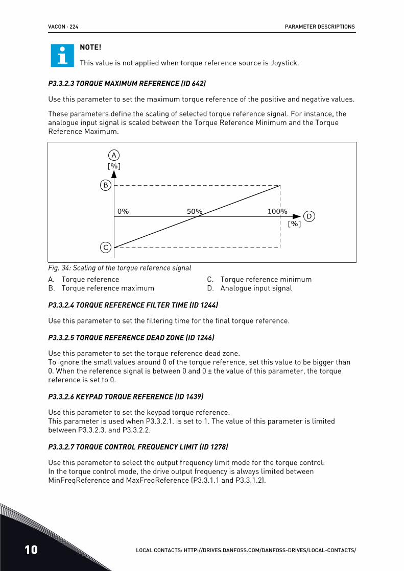
NOTE!
This value is not applied when torque reference source is Joystick.
P3.3.2.3 TORQUE MAXIMUM REFERENCE (ID 642)
Use this parameter to set the maximum torque reference of the positive and negative values.
These parameters define the scaling of selected torque reference signal. For instance, theanalogue input signal is scaled between the Torque Reference Minimum and the TorqueReference Maximum.
100%0% 50%
C
B
D
A[%]
[%]
Fig. 34: Scaling of the torque reference signalA. Torque referenceB. Torque reference maximum
C. Torque reference minimumD. Analogue input signal
P3.3.2.4 TORQUE REFERENCE FILTER TIME (ID 1244)
Use this parameter to set the filtering time for the final torque reference.
P3.3.2.5 TORQUE REFERENCE DEAD ZONE (ID 1246)
Use this parameter to set the torque reference dead zone.To ignore the small values around 0 of the torque reference, set this value to be bigger than0. When the reference signal is between 0 and 0 ± the value of this parameter, the torquereference is set to 0.
P3.3.2.6 KEYPAD TORQUE REFERENCE (ID 1439)
Use this parameter to set the keypad torque reference.This parameter is used when P3.3.2.1. is set to 1. The value of this parameter is limitedbetween P3.3.2.3. and P3.3.2.2.
P3.3.2.7 TORQUE CONTROL FREQUENCY LIMIT (ID 1278)
Use this parameter to select the output frequency limit mode for the torque control.In the torque control mode, the drive output frequency is always limited betweenMinFreqReference and MaxFreqReference (P3.3.1.1 and P3.3.1.2).
VACON · 224 PARAMETER DESCRIPTIONS
10 LOCAL CONTACTS: HTTP://DRIVES.DANFOSS.COM/DANFOSS-DRIVES/LOCAL-CONTACTS/
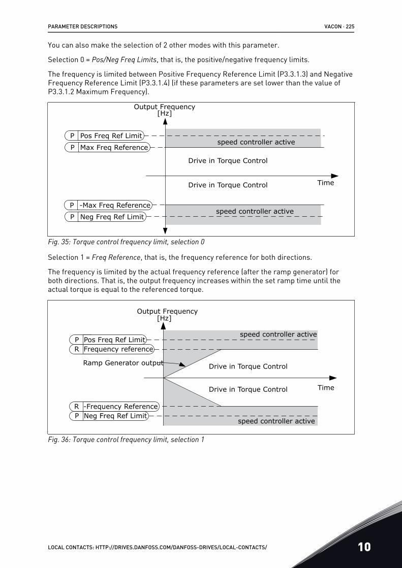
You can also make the selection of 2 other modes with this parameter.
Selection 0 = Pos/Neg Freq Limits, that is, the positive/negative frequency limits.
The frequency is limited between Positive Frequency Reference Limit (P3.3.1.3) and NegativeFrequency Reference Limit (P3.3.1.4) (if these parameters are set lower than the value ofP3.3.1.2 Maximum Frequency).
speed controller active
speed controller active
P Max Freq Reference
P -Max Freq Reference
Time
Drive in Torque Control
Drive in Torque Control
Output Frequency[Hz]
P Pos Freq Ref Limit
P Neg Freq Ref Limit
Fig. 35: Torque control frequency limit, selection 0
Selection 1 = Freq Reference, that is, the frequency reference for both directions.
The frequency is limited by the actual frequency reference (after the ramp generator) forboth directions. That is, the output frequency increases within the set ramp time until theactual torque is equal to the referenced torque.
speed controller active
speed controller active
Ramp Generator output
P Pos Freq Ref Limit
P Neg Freq Ref Limit
R Frequency reference
R -Frequency Reference
Output Frequency
Drive in Torque Control
Drive in Torque Control Time
[Hz]
Fig. 36: Torque control frequency limit, selection 1
PARAMETER DESCRIPTIONS VACON · 225
LOCAL CONTACTS: HTTP://DRIVES.DANFOSS.COM/DANFOSS-DRIVES/LOCAL-CONTACTS/ 10
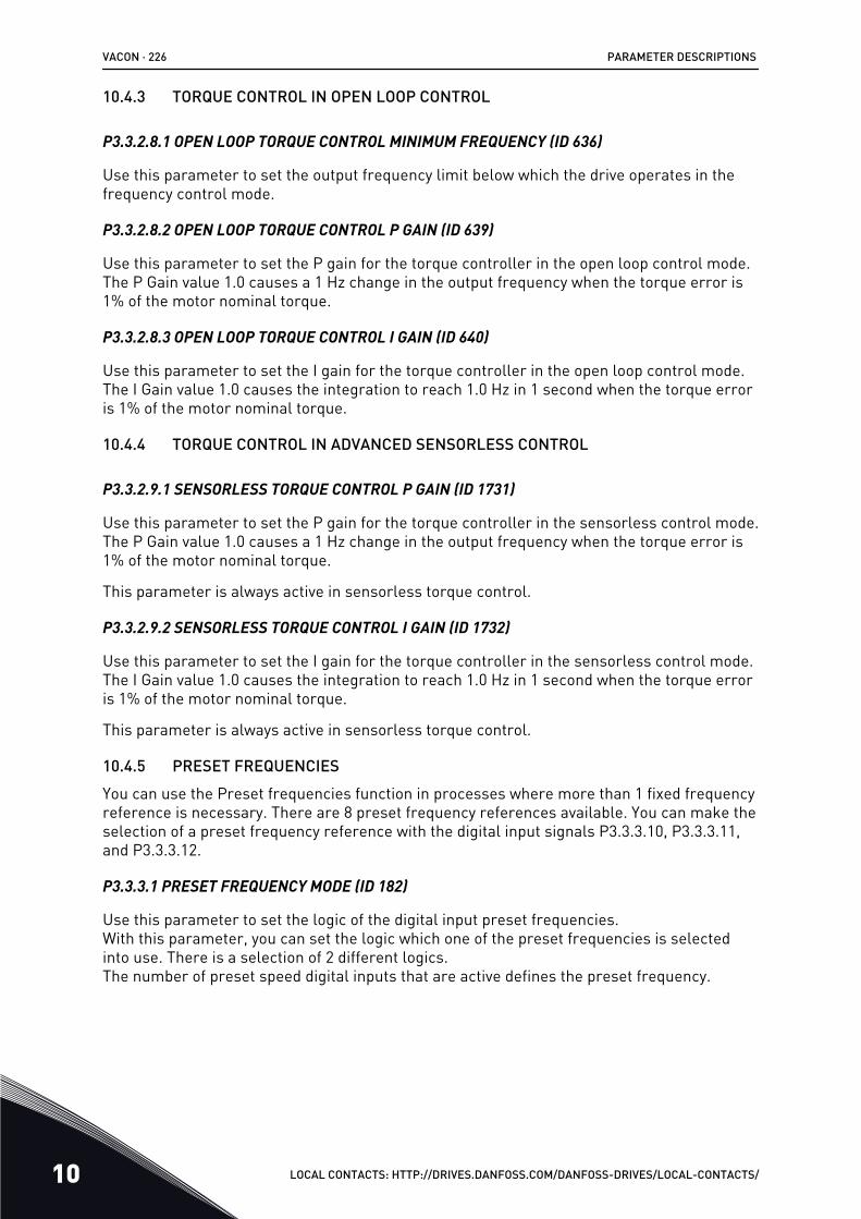
10.4.3 TORQUE CONTROL IN OPEN LOOP CONTROL
P3.3.2.8.1 OPEN LOOP TORQUE CONTROL MINIMUM FREQUENCY (ID 636)
Use this parameter to set the output frequency limit below which the drive operates in thefrequency control mode.
P3.3.2.8.2 OPEN LOOP TORQUE CONTROL P GAIN (ID 639)
Use this parameter to set the P gain for the torque controller in the open loop control mode.The P Gain value 1.0 causes a 1 Hz change in the output frequency when the torque error is1% of the motor nominal torque.
P3.3.2.8.3 OPEN LOOP TORQUE CONTROL I GAIN (ID 640)
Use this parameter to set the I gain for the torque controller in the open loop control mode.The I Gain value 1.0 causes the integration to reach 1.0 Hz in 1 second when the torque erroris 1% of the motor nominal torque.
10.4.4 TORQUE CONTROL IN ADVANCED SENSORLESS CONTROL
P3.3.2.9.1 SENSORLESS TORQUE CONTROL P GAIN (ID 1731)
Use this parameter to set the P gain for the torque controller in the sensorless control mode.The P Gain value 1.0 causes a 1 Hz change in the output frequency when the torque error is1% of the motor nominal torque.
This parameter is always active in sensorless torque control.
P3.3.2.9.2 SENSORLESS TORQUE CONTROL I GAIN (ID 1732)
Use this parameter to set the I gain for the torque controller in the sensorless control mode.The I Gain value 1.0 causes the integration to reach 1.0 Hz in 1 second when the torque erroris 1% of the motor nominal torque.
This parameter is always active in sensorless torque control.
10.4.5 PRESET FREQUENCIESYou can use the Preset frequencies function in processes where more than 1 fixed frequencyreference is necessary. There are 8 preset frequency references available. You can make theselection of a preset frequency reference with the digital input signals P3.3.3.10, P3.3.3.11,and P3.3.3.12.
P3.3.3.1 PRESET FREQUENCY MODE (ID 182)
Use this parameter to set the logic of the digital input preset frequencies.With this parameter, you can set the logic which one of the preset frequencies is selectedinto use. There is a selection of 2 different logics.The number of preset speed digital inputs that are active defines the preset frequency.
VACON · 226 PARAMETER DESCRIPTIONS
10 LOCAL CONTACTS: HTTP://DRIVES.DANFOSS.COM/DANFOSS-DRIVES/LOCAL-CONTACTS/
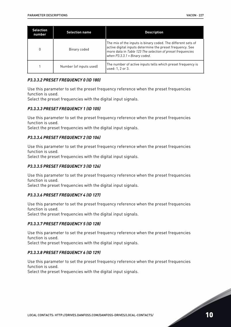
Selectionnumber Selection name Description
0 Binary coded
The mix of the inputs is binary coded. The different sets ofactive digital inputs determine the preset frequency. Seemore data in Table 123 The selection of preset frequencies when P3.3.3.1 = Binary coded.
1 Number (of inputs used) The number of active inputs tells which preset frequency isused: 1, 2 or 3.
P3.3.3.2 PRESET FREQUENCY 0 (ID 180)
Use this parameter to set the preset frequency reference when the preset frequenciesfunction is used.Select the preset frequencies with the digital input signals.
P3.3.3.3 PRESET FREQUENCY 1 (ID 105)
Use this parameter to set the preset frequency reference when the preset frequenciesfunction is used.Select the preset frequencies with the digital input signals.
P3.3.3.4 PRESET FREQUENCY 2 (ID 106)
Use this parameter to set the preset frequency reference when the preset frequenciesfunction is used.Select the preset frequencies with the digital input signals.
P3.3.3.5 PRESET FREQUENCY 3 (ID 126)
Use this parameter to set the preset frequency reference when the preset frequenciesfunction is used.Select the preset frequencies with the digital input signals.
P3.3.3.6 PRESET FREQUENCY 4 (ID 127)
Use this parameter to set the preset frequency reference when the preset frequenciesfunction is used.Select the preset frequencies with the digital input signals.
P3.3.3.7 PRESET FREQUENCY 5 (ID 128)
Use this parameter to set the preset frequency reference when the preset frequenciesfunction is used.Select the preset frequencies with the digital input signals.
P3.3.3.8 PRESET FREQUENCY 6 (ID 129)
Use this parameter to set the preset frequency reference when the preset frequenciesfunction is used.Select the preset frequencies with the digital input signals.
PARAMETER DESCRIPTIONS VACON · 227
LOCAL CONTACTS: HTTP://DRIVES.DANFOSS.COM/DANFOSS-DRIVES/LOCAL-CONTACTS/ 10
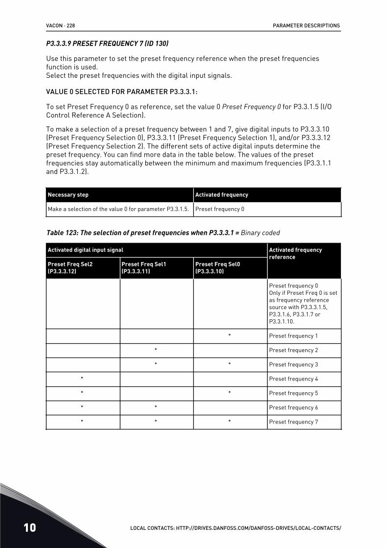
P3.3.3.9 PRESET FREQUENCY 7 (ID 130)
Use this parameter to set the preset frequency reference when the preset frequenciesfunction is used.Select the preset frequencies with the digital input signals.
VALUE 0 SELECTED FOR PARAMETER P3.3.3.1:
To set Preset Frequency 0 as reference, set the value 0 Preset Frequency 0 for P3.3.1.5 (I/OControl Reference A Selection).
To make a selection of a preset frequency between 1 and 7, give digital inputs to P3.3.3.10(Preset Frequency Selection 0), P3.3.3.11 (Preset Frequency Selection 1), and/or P3.3.3.12(Preset Frequency Selection 2). The different sets of active digital inputs determine thepreset frequency. You can find more data in the table below. The values of the presetfrequencies stay automatically between the minimum and maximum frequencies (P3.3.1.1and P3.3.1.2).
Necessary step Activated frequency
Make a selection of the value 0 for parameter P3.3.1.5. Preset frequency 0
Table 123: The selection of preset frequencies when P3.3.3.1 = Binary coded
Activated digital input signal Activated frequencyreference
Preset Freq Sel2(P3.3.3.12)
Preset Freq Sel1(P3.3.3.11)
Preset Freq Sel0(P3.3.3.10)
Preset frequency 0Only if Preset Freq 0 is setas frequency referencesource with P3.3.3.1.5,P3.3.1.6, P3.3.1.7 orP3.3.1.10.
* Preset frequency 1
* Preset frequency 2
* * Preset frequency 3
* Preset frequency 4
* * Preset frequency 5
* * Preset frequency 6
* * * Preset frequency 7
VACON · 228 PARAMETER DESCRIPTIONS
10 LOCAL CONTACTS: HTTP://DRIVES.DANFOSS.COM/DANFOSS-DRIVES/LOCAL-CONTACTS/
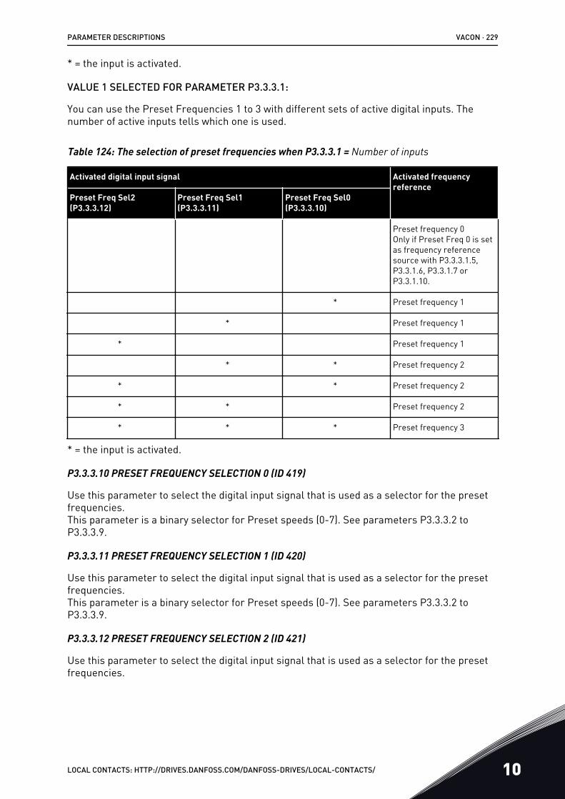
* = the input is activated.
VALUE 1 SELECTED FOR PARAMETER P3.3.3.1:
You can use the Preset Frequencies 1 to 3 with different sets of active digital inputs. Thenumber of active inputs tells which one is used.
Table 124: The selection of preset frequencies when P3.3.3.1 = Number of inputs
Activated digital input signal Activated frequencyreference
Preset Freq Sel2(P3.3.3.12)
Preset Freq Sel1(P3.3.3.11)
Preset Freq Sel0(P3.3.3.10)
Preset frequency 0Only if Preset Freq 0 is setas frequency referencesource with P3.3.3.1.5,P3.3.1.6, P3.3.1.7 orP3.3.1.10.
* Preset frequency 1
* Preset frequency 1
* Preset frequency 1
* * Preset frequency 2
* * Preset frequency 2
* * Preset frequency 2
* * * Preset frequency 3
* = the input is activated.
P3.3.3.10 PRESET FREQUENCY SELECTION 0 (ID 419)
Use this parameter to select the digital input signal that is used as a selector for the presetfrequencies.This parameter is a binary selector for Preset speeds (0-7). See parameters P3.3.3.2 toP3.3.3.9.
P3.3.3.11 PRESET FREQUENCY SELECTION 1 (ID 420)
Use this parameter to select the digital input signal that is used as a selector for the presetfrequencies.This parameter is a binary selector for Preset speeds (0-7). See parameters P3.3.3.2 toP3.3.3.9.
P3.3.3.12 PRESET FREQUENCY SELECTION 2 (ID 421)
Use this parameter to select the digital input signal that is used as a selector for the presetfrequencies.
PARAMETER DESCRIPTIONS VACON · 229
LOCAL CONTACTS: HTTP://DRIVES.DANFOSS.COM/DANFOSS-DRIVES/LOCAL-CONTACTS/ 10
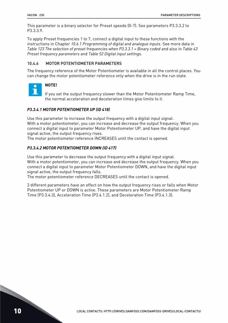
This parameter is a binary selector for Preset speeds (0-7). See parameters P3.3.3.2 toP3.3.3.9.
To apply Preset frequencies 1 to 7, connect a digital input to these functions with theinstructions in Chapter 10.6.1 Programming of digital and analogue inputs. See more data inTable 123 The selection of preset frequencies when P3.3.3.1 = Binary coded and also in Table 43 Preset frequency parameters and Table 52 Digital input settings.
10.4.6 MOTOR POTENTIOMETER PARAMETERSThe frequency reference of the Motor Potentiometer is available in all the control places. Youcan change the motor potentiometer reference only when the drive is in the run state.
NOTE!
If you set the output frequency slower than the Motor Potentiometer Ramp Time,the normal acceleration and deceleration times give limits to it.
P3.3.4.1 MOTOR POTENTIOMETER UP (ID 418)
Use this parameter to increase the output frequency with a digital input signal.With a motor potentiometer, you can increase and decrease the output frequency. When youconnect a digital input to parameter Motor Potentiometer UP, and have the digital inputsignal active, the output frequency rises.The motor potentiometer reference INCREASES until the contact is opened.
P3.3.4.2 MOTOR POTENTIOMETER DOWN (ID 417)
Use this parameter to decrease the output frequency with a digital input signal.With a motor potentiometer, you can increase and decrease the output frequency. When youconnect a digital input to parameter Motor Potentiometer DOWN, and have the digital inputsignal active, the output frequency falls.The motor potentiometer reference DECREASES until the contact is opened.
3 different parameters have an effect on how the output frequency rises or falls when MotorPotentiometer UP or DOWN is active. These parameters are Motor Potentiometer RampTime (P3.3.4.3), Acceleration Time (P3.4.1.2), and Deceleration Time (P3.4.1.3).
VACON · 230 PARAMETER DESCRIPTIONS
10 LOCAL CONTACTS: HTTP://DRIVES.DANFOSS.COM/DANFOSS-DRIVES/LOCAL-CONTACTS/
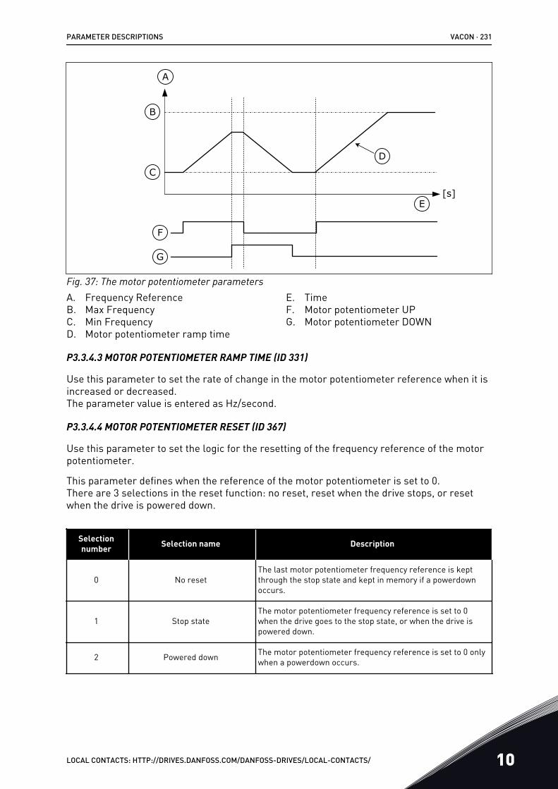
C
B
F
D
A
G
E[s]
Fig. 37: The motor potentiometer parametersA. Frequency ReferenceB. Max FrequencyC. Min FrequencyD. Motor potentiometer ramp time
E. TimeF. Motor potentiometer UPG. Motor potentiometer DOWN
P3.3.4.3 MOTOR POTENTIOMETER RAMP TIME (ID 331)
Use this parameter to set the rate of change in the motor potentiometer reference when it isincreased or decreased.The parameter value is entered as Hz/second.
P3.3.4.4 MOTOR POTENTIOMETER RESET (ID 367)
Use this parameter to set the logic for the resetting of the frequency reference of the motorpotentiometer.
This parameter defines when the reference of the motor potentiometer is set to 0.There are 3 selections in the reset function: no reset, reset when the drive stops, or resetwhen the drive is powered down.
Selectionnumber Selection name Description
0 No resetThe last motor potentiometer frequency reference is keptthrough the stop state and kept in memory if a powerdownoccurs.
1 Stop stateThe motor potentiometer frequency reference is set to 0when the drive goes to the stop state, or when the drive ispowered down.
2 Powered down The motor potentiometer frequency reference is set to 0 onlywhen a powerdown occurs.
PARAMETER DESCRIPTIONS VACON · 231
LOCAL CONTACTS: HTTP://DRIVES.DANFOSS.COM/DANFOSS-DRIVES/LOCAL-CONTACTS/ 10
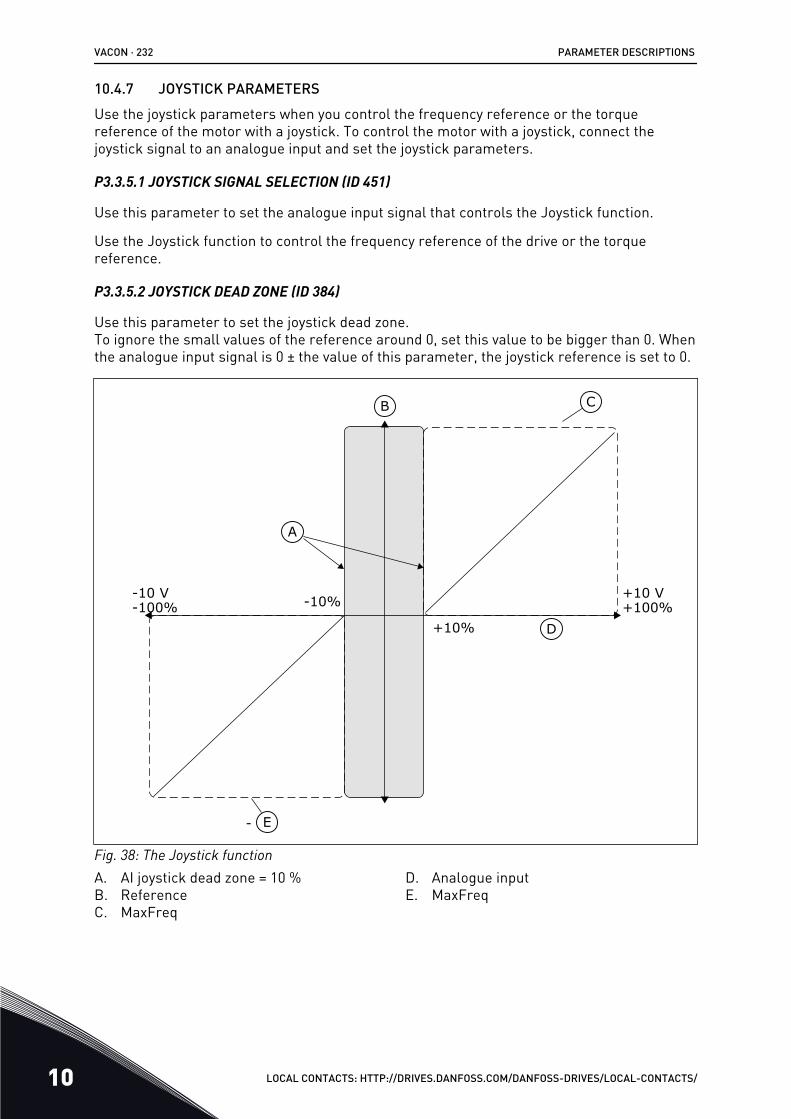
10.4.7 JOYSTICK PARAMETERSUse the joystick parameters when you control the frequency reference or the torquereference of the motor with a joystick. To control the motor with a joystick, connect thejoystick signal to an analogue input and set the joystick parameters.
P3.3.5.1 JOYSTICK SIGNAL SELECTION (ID 451)
Use this parameter to set the analogue input signal that controls the Joystick function.
Use the Joystick function to control the frequency reference of the drive or the torquereference.
P3.3.5.2 JOYSTICK DEAD ZONE (ID 384)
Use this parameter to set the joystick dead zone.To ignore the small values of the reference around 0, set this value to be bigger than 0. Whenthe analogue input signal is 0 ± the value of this parameter, the joystick reference is set to 0.
-
CB
D
A
E
-10 V +10 V-100% +100%-10%
+10%
Fig. 38: The Joystick functionA. AI joystick dead zone = 10 %B. ReferenceC. MaxFreq
D. Analogue inputE. MaxFreq
VACON · 232 PARAMETER DESCRIPTIONS
10 LOCAL CONTACTS: HTTP://DRIVES.DANFOSS.COM/DANFOSS-DRIVES/LOCAL-CONTACTS/
P3.3.5.3 JOYSTICK SLEEP ZONE (ID 385)
Use this parameter to set the joystick sleep zone.The AC drive stops if the joystick reference stays in the sleep zone for longer than the timeperiod defined in parameter P3.3.5.4 Joystick Sleep Delay.
NOTE!
The Sleep function is available only if you use the joystick to control the frequencyreference.
P3.3.5.4 JOYSTICK SLEEP DELAY (ID 386)
Use this parameter to set the joystick sleep delay.If the joystick reference stays in the set sleep zone for longer than the sleep delay, the drivestops and the sleep mode is activated.
NOTE!
The Joystick sleep function is disabled when the value of this parameter is set to 0.
10.4.8 JOGGING PARAMETERSUse the Jogging function to override the normal control momentarily. You can use thisfunction, for example, to control the process slowly to a special status or position duringmaintenance. You do not have to change the control place or other parameters.
Only when the drive is in stop state, it is possible to activate the Jogging function. You canuse 2 bi-directional frequency references. You can activate the Jogging function from thefieldbus or by digital input signals. The Jogging function has a ramp time that is used alwayswhen jogging is active.
The Jogging function starts the drive at the set reference. A new start command is notnecessary. The control place does not have an effect on this.
You can activate the Jogging function from the fieldbus in bypass mode with Control Wordbits 10 and 11.
PARAMETER DESCRIPTIONS VACON · 233
LOCAL CONTACTS: HTTP://DRIVES.DANFOSS.COM/DANFOSS-DRIVES/LOCAL-CONTACTS/ 10
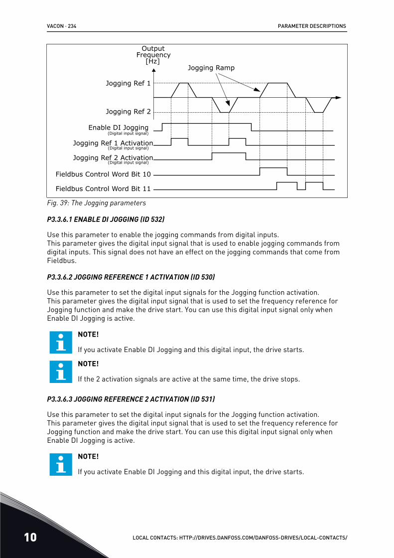
Jogging Ref 1
OutputFrequency
[Hz]
Jogging Ref 2
Jogging Ref 2 Activation(Digital input signal)
Jogging Ref 1 Activation(Digital input signal)
Enable DI Jogging(Digital input signal)
Jogging Ramp
Fieldbus Control Word Bit 11
Fieldbus Control Word Bit 10
Fig. 39: The Jogging parameters
P3.3.6.1 ENABLE DI JOGGING (ID 532)
Use this parameter to enable the jogging commands from digital inputs.This parameter gives the digital input signal that is used to enable jogging commands fromdigital inputs. This signal does not have an effect on the jogging commands that come fromFieldbus.
P3.3.6.2 JOGGING REFERENCE 1 ACTIVATION (ID 530)
Use this parameter to set the digital input signals for the Jogging function activation.This parameter gives the digital input signal that is used to set the frequency reference forJogging function and make the drive start. You can use this digital input signal only whenEnable DI Jogging is active.
NOTE!
If you activate Enable DI Jogging and this digital input, the drive starts.
NOTE!
If the 2 activation signals are active at the same time, the drive stops.
P3.3.6.3 JOGGING REFERENCE 2 ACTIVATION (ID 531)
Use this parameter to set the digital input signals for the Jogging function activation.This parameter gives the digital input signal that is used to set the frequency reference forJogging function and make the drive start. You can use this digital input signal only whenEnable DI Jogging is active.
NOTE!
If you activate Enable DI Jogging and this digital input, the drive starts.
VACON · 234 PARAMETER DESCRIPTIONS
10 LOCAL CONTACTS: HTTP://DRIVES.DANFOSS.COM/DANFOSS-DRIVES/LOCAL-CONTACTS/
NOTE!
If the 2 activation signals are active at the same time, the drive stops.
P3.3.6.4 JOGGING REFERENCE 1 (ID 1239)
Use this parameter to set the frequency references for the jogging function.With the parameters P3.3.6.4 and P3.3.6.5, you can set the frequency references for thejogging function. The references are bi-directional. A reverse command does not have aneffect on the direction of the jogging references. The reference for the forward direction hasa positive value, and the reference for the reverse direction has a negative value. You canactivate the jogging function with digital input signals or from Fieldbus in bypass mode withControl Word bits 10 and 11.
P3.3.6.5 JOGGING REFERENCE 2 (ID 1240)
Use this parameter to set the frequency references for the jogging function.With the parameters P3.3.6.4 and P3.3.6.5, you can set the frequency references for thejogging function. The references are bi-directional. A reverse command does not have aneffect on the direction of the jogging references. The reference for the forward direction hasa positive value, and the reference for the reverse direction has a negative value. You canactivate the jogging function with digital input signals or from Fieldbus in bypass mode withControl Word bits 10 and 11.
P3.3.6.6 JOGGING RAMP (ID 1257)
Use this parameter to set the ramp time when jogging is active.This parameter gives the acceleration and deceleration times when the Jogging function isactive.
10.5 RAMPS AND BRAKES SETUP
10.5.1 RAMP 1
P3.4.1.1 RAMP 1 SHAPE (ID 500)
Use this parameter to make the start and the end of the acceleration and deceleration rampssmoother.With the parameters Ramp 1 Shape and Ramp 2 Shape, you can make smoother the startand the end of the acceleration and deceleration ramps. If you set the value to 0.0%, you geta linear ramp shape. The acceleration and deceleration act immediately to the changes inthe reference signal.
When you set the value between 1.0% and 100.0%, you get an S-shaped acceleration ordeceleration ramp. Use this function to reduce mechanical erosion of the parts and currentspikes when the reference changes. You can modify the acceleration time with parametersP3.4.1.2 (Acceleration Time 1) and P3.4.1.3 (Deceleration Time 1).
PARAMETER DESCRIPTIONS VACON · 235
LOCAL CONTACTS: HTTP://DRIVES.DANFOSS.COM/DANFOSS-DRIVES/LOCAL-CONTACTS/ 10
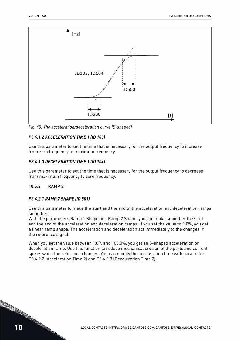
[t]
[Hz]
ID103, ID104
ID500
ID500
Fig. 40: The acceleration/deceleration curve (S-shaped)
P3.4.1.2 ACCELERATION TIME 1 (ID 103)
Use this parameter to set the time that is necessary for the output frequency to increasefrom zero frequency to maximum frequency.
P3.4.1.3 DECELERATION TIME 1 (ID 104)
Use this parameter to set the time that is necessary for the output frequency to decreasefrom maximum frequency to zero frequency.
10.5.2 RAMP 2
P3.4.2.1 RAMP 2 SHAPE (ID 501)
Use this parameter to make the start and the end of the acceleration and deceleration rampssmoother.With the parameters Ramp 1 Shape and Ramp 2 Shape, you can make smoother the startand the end of the acceleration and deceleration ramps. If you set the value to 0.0%, you geta linear ramp shape. The acceleration and deceleration act immediately to the changes inthe reference signal.
When you set the value between 1.0% and 100.0%, you get an S-shaped acceleration ordeceleration ramp. Use this function to reduce mechanical erosion of the parts and currentspikes when the reference changes. You can modify the acceleration time with parametersP3.4.2.2 (Acceleration Time 2) and P3.4.2.3 (Deceleration Time 2).
VACON · 236 PARAMETER DESCRIPTIONS
10 LOCAL CONTACTS: HTTP://DRIVES.DANFOSS.COM/DANFOSS-DRIVES/LOCAL-CONTACTS/
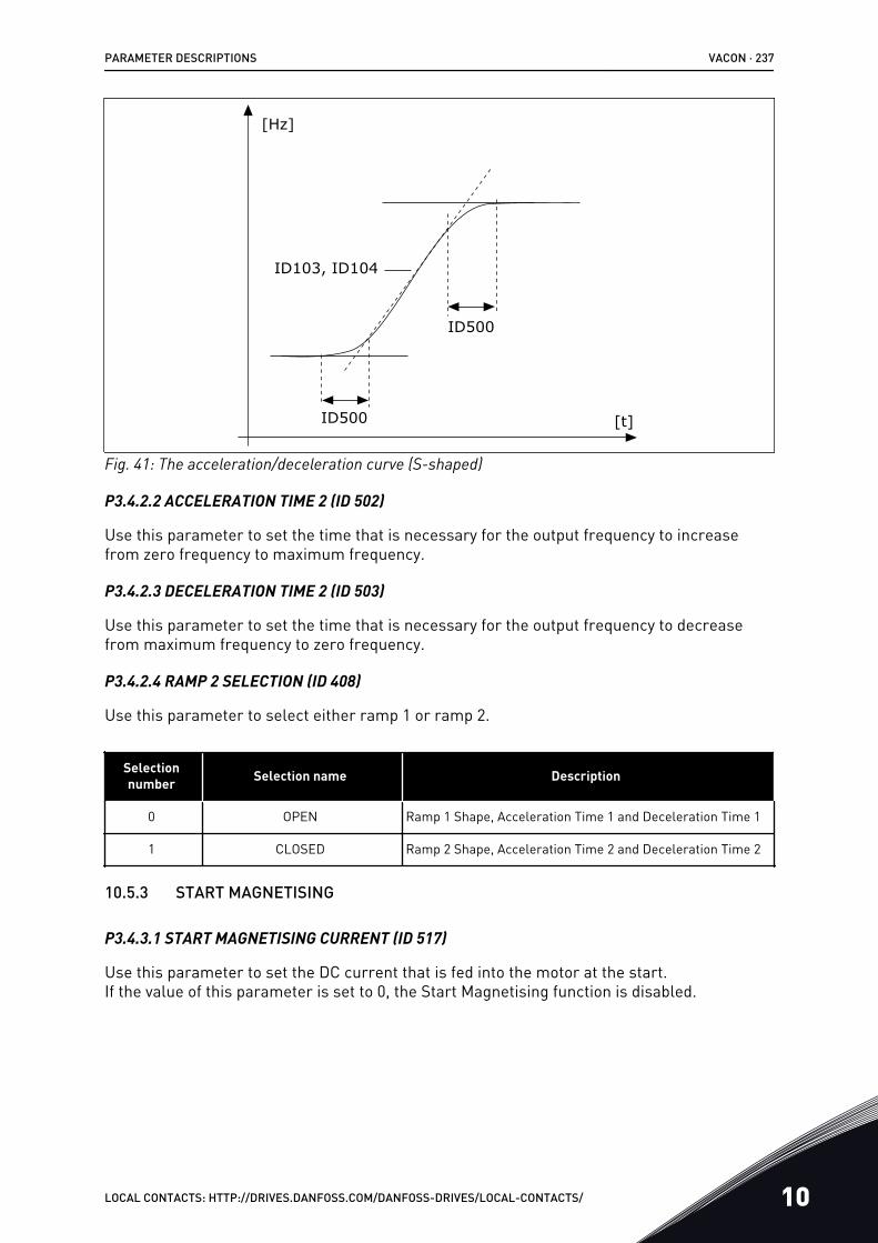
[t]
[Hz]
ID103, ID104
ID500
ID500
Fig. 41: The acceleration/deceleration curve (S-shaped)
P3.4.2.2 ACCELERATION TIME 2 (ID 502)
Use this parameter to set the time that is necessary for the output frequency to increasefrom zero frequency to maximum frequency.
P3.4.2.3 DECELERATION TIME 2 (ID 503)
Use this parameter to set the time that is necessary for the output frequency to decreasefrom maximum frequency to zero frequency.
P3.4.2.4 RAMP 2 SELECTION (ID 408)
Use this parameter to select either ramp 1 or ramp 2.
Selectionnumber Selection name Description
0 OPEN Ramp 1 Shape, Acceleration Time 1 and Deceleration Time 1
1 CLOSED Ramp 2 Shape, Acceleration Time 2 and Deceleration Time 2
10.5.3 START MAGNETISING
P3.4.3.1 START MAGNETISING CURRENT (ID 517)
Use this parameter to set the DC current that is fed into the motor at the start.If the value of this parameter is set to 0, the Start Magnetising function is disabled.
PARAMETER DESCRIPTIONS VACON · 237
LOCAL CONTACTS: HTTP://DRIVES.DANFOSS.COM/DANFOSS-DRIVES/LOCAL-CONTACTS/ 10
P3.4.3.2 START MAGNETISING TIME (ID 516)
Use this parameter to set the time during which the DC current is fed to the motor before theacceleration starts.
10.5.4 DC BRAKE
P3.4.4.1 DC BRAKE CURRENT (ID 507)
Use this parameter to set the current that is fed into the motor during DC braking.If the value of this parameter is set to 0, the DC Brake function is disabled.
P3.4.4.2 DC BRAKING TIME AT STOP (ID 508)
Use this parameter to set the braking is ON or OFF and to give the braking time when themotor stops.If the value of this parameter is set to 0, the DC Brake function is disabled.
P3.4.4.3 FREQUENCY TO START DC BRAKING AT RAMP STOP (ID 515)
Use this parameter to set the output frequency at which the DC braking starts.
10.5.5 FLUX BRAKING
P3.4.5.1 FLUX BRAKING (ID 520)
Use this parameter to enable Flux Braking.You can use flux braking as an alternative to DC braking. Flux braking increases the brakingcapacity in conditions where additional brake resistors are not necessary.
When braking is necessary, the system decreases the frequency and increases the flux in themotor. This increases the capacity of the motor to brake. The motor speed is controlledduring braking.
CAUTION!
Use the braking only intermittently. Flux braking converts energy into heat and cancause damage to the motor.
P3.4.5.2 FLUX BRAKING CURRENT (ID 519)
Use this parameter to set the current level for the flux braking.
10.6 I/O CONFIGURATION
10.6.1 PROGRAMMING OF DIGITAL AND ANALOGUE INPUTSThe programming of inputs of the AC drive is flexible. You can freely use the available inputsof the standard and optional I/O for different functions.
VACON · 238 PARAMETER DESCRIPTIONS
10 LOCAL CONTACTS: HTTP://DRIVES.DANFOSS.COM/DANFOSS-DRIVES/LOCAL-CONTACTS/
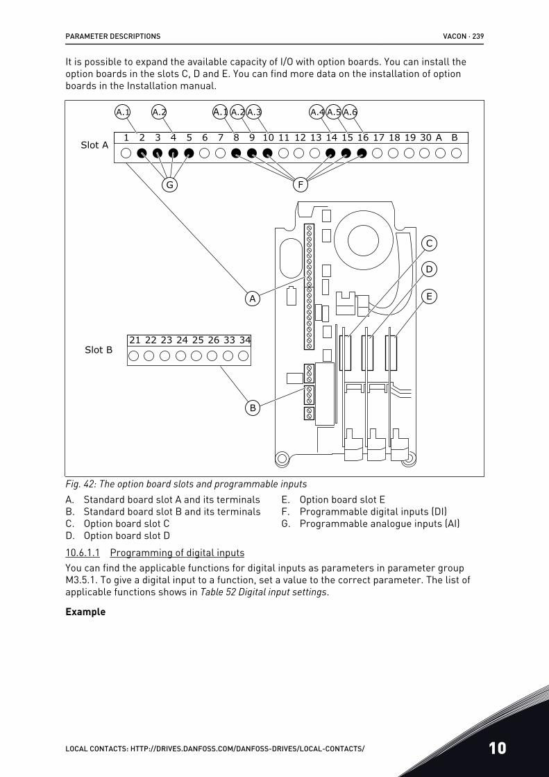
It is possible to expand the available capacity of I/O with option boards. You can install theoption boards in the slots C, D and E. You can find more data on the installation of optionboards in the Installation manual.
21 3 4 5 6 7 8 9 10 11 12 13 14 15 16 17 18 19 30 A B
21 22 23 24 25 26 33 34
Slot A
Slot B
C
A
B
D
E
A.1
G F
A.2 A.1 A.2 A.3 A.4 A.5 A.6
Fig. 42: The option board slots and programmable inputsA. Standard board slot A and its terminalsB. Standard board slot B and its terminalsC. Option board slot CD. Option board slot D
E. Option board slot EF. Programmable digital inputs (DI)G. Programmable analogue inputs (AI)
10.6.1.1 Programming of digital inputsYou can find the applicable functions for digital inputs as parameters in parameter groupM3.5.1. To give a digital input to a function, set a value to the correct parameter. The list ofapplicable functions shows in Table 52 Digital input settings.
Example
PARAMETER DESCRIPTIONS VACON · 239
LOCAL CONTACTS: HTTP://DRIVES.DANFOSS.COM/DANFOSS-DRIVES/LOCAL-CONTACTS/ 10
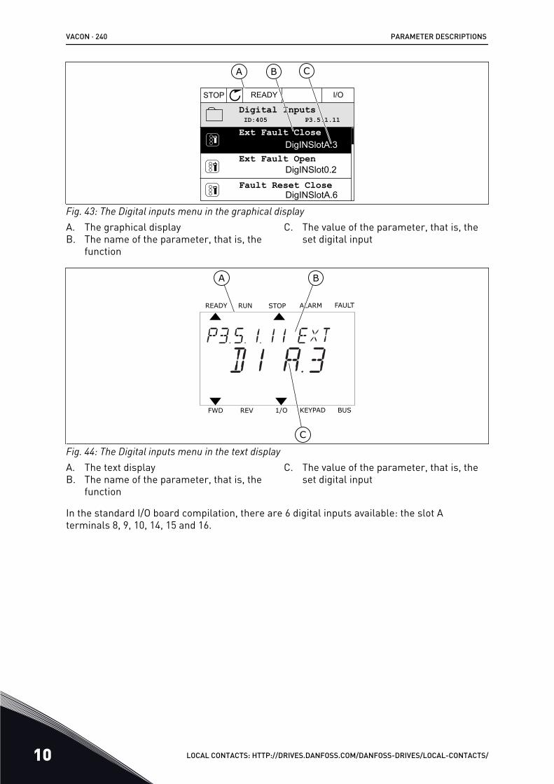
STOP READY I/O
ID:405 P3.5.1.11Digital Inputs
BA C
DigINSlotA.3
DigINSlot0.2
DigINSlotA.6Fault Reset Close
Ext Fault Open
Ext Fault Close
Fig. 43: The Digital inputs menu in the graphical displayA. The graphical displayB. The name of the parameter, that is, the
function
C. The value of the parameter, that is, theset digital input
READY FAULTALARMSTOPRUN
KEYPAD1/OREVFWD BUS
A B
C
Fig. 44: The Digital inputs menu in the text displayA. The text displayB. The name of the parameter, that is, the
function
C. The value of the parameter, that is, theset digital input
In the standard I/O board compilation, there are 6 digital inputs available: the slot Aterminals 8, 9, 10, 14, 15 and 16.
VACON · 240 PARAMETER DESCRIPTIONS
10 LOCAL CONTACTS: HTTP://DRIVES.DANFOSS.COM/DANFOSS-DRIVES/LOCAL-CONTACTS/
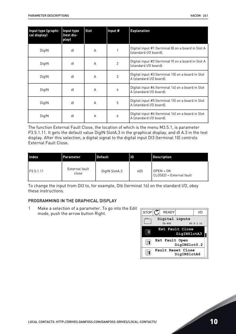
Input type (graphi-cal display)
Input type(text dis-play)
Slot Input # Explanation
DigIN dI A 1 Digital input #1 (terminal 8) on a board in Slot A(standard I/O board).
DigIN dI A 2 Digital input #2 (terminal 9) on a board in Slot A(standard I/O board).
DigIN dI A 3 Digital input #3 (terminal 10) on a board in SlotA (standard I/O board).
DigIN dI A 4 Digital input #4 (terminal 14) on a board in SlotA (standard I/O board).
DigIN dI A 5 Digital input #5 (terminal 15) on a board in SlotA (standard I/O board).
DigIN dI A 6 Digital input #6 (terminal 16) on a board in SlotA (standard I/O board).
The function External Fault Close, the location of which is the menu M3.5.1, is parameterP3.5.1.11. It gets the default value DigIN SlotA.3 in the graphical display, and dI A.3 in the textdisplay. After this selection, a digital signal to the digital input DI3 (terminal 10) controlsExternal Fault Close.
Index Parameter Default ID Description
P3.5.1.11 External faultclose DigIN SlotA.3 405 OPEN = OK
CLOSED = External fault
To change the input from DI3 to, for example, DI6 (terminal 16) on the standard I/O, obeythese instructions.
PROGRAMMING IN THE GRAPHICAL DISPLAY1 Make a selection of a parameter. To go into the Edit
mode, push the arrow button Right. STOP READY I/O
Digital inputs
Ext Fault Open
Fault Reset Close
DigINSlotA3
DigINSlot0.2
DigINSlotA6
Ext Fault CloseP3.5.1.11ID:405
PARAMETER DESCRIPTIONS VACON · 241
LOCAL CONTACTS: HTTP://DRIVES.DANFOSS.COM/DANFOSS-DRIVES/LOCAL-CONTACTS/ 10
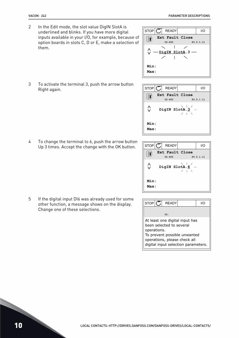
2 In the Edit mode, the slot value DigIN SlotA isunderlined and blinks. If you have more digitalinputs available in your I/O, for example, because ofoption boards in slots C, D or E, make a selection ofthem.
STOP READY I/O
Ext Fault CloseP3.5.1.11ID:405
Min:Max:
DigIN SlotA.3
3 To activate the terminal 3, push the arrow buttonRight again. STOP READY I/O
Ext Fault CloseP3.5.1.11ID:405
Min:Max:
DigIN SlotA.3
4 To change the terminal to 6, push the arrow buttonUp 3 times. Accept the change with the OK button. STOP READY I/O
Ext Fault CloseP3.5.1.11ID:405
Min:Max:
DigIN SlotA.6
5 If the digital input DI6 was already used for someother function, a message shows on the display.Change one of these selections.
STOP READY I/O
ID:
At least one digital input has been selected to several operations.To prevent possible unwanted operations, please check all digital input selection parameters.
VACON · 242 PARAMETER DESCRIPTIONS
10 LOCAL CONTACTS: HTTP://DRIVES.DANFOSS.COM/DANFOSS-DRIVES/LOCAL-CONTACTS/
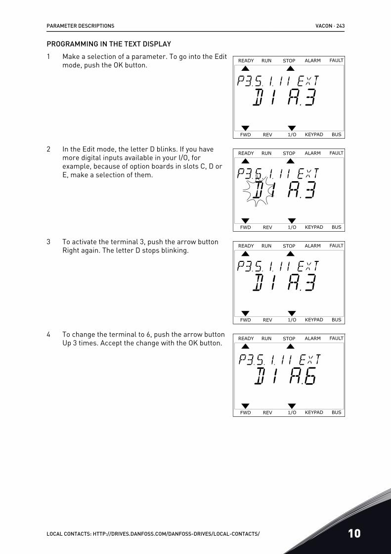
PROGRAMMING IN THE TEXT DISPLAY1 Make a selection of a parameter. To go into the Edit
mode, push the OK button.READY FAULTALARMSTOPRUN
KEYPAD1/OREVFWD BUS
2 In the Edit mode, the letter D blinks. If you havemore digital inputs available in your I/O, forexample, because of option boards in slots C, D orE, make a selection of them.
READY FAULTALARMSTOPRUN
KEYPAD1/OREVFWD BUS
3 To activate the terminal 3, push the arrow buttonRight again. The letter D stops blinking.
READY FAULTALARMSTOPRUN
KEYPAD1/OREVFWD BUS
4 To change the terminal to 6, push the arrow buttonUp 3 times. Accept the change with the OK button.
READY FAULTALARMSTOPRUN
KEYPAD1/OREVFWD BUS
PARAMETER DESCRIPTIONS VACON · 243
LOCAL CONTACTS: HTTP://DRIVES.DANFOSS.COM/DANFOSS-DRIVES/LOCAL-CONTACTS/ 10
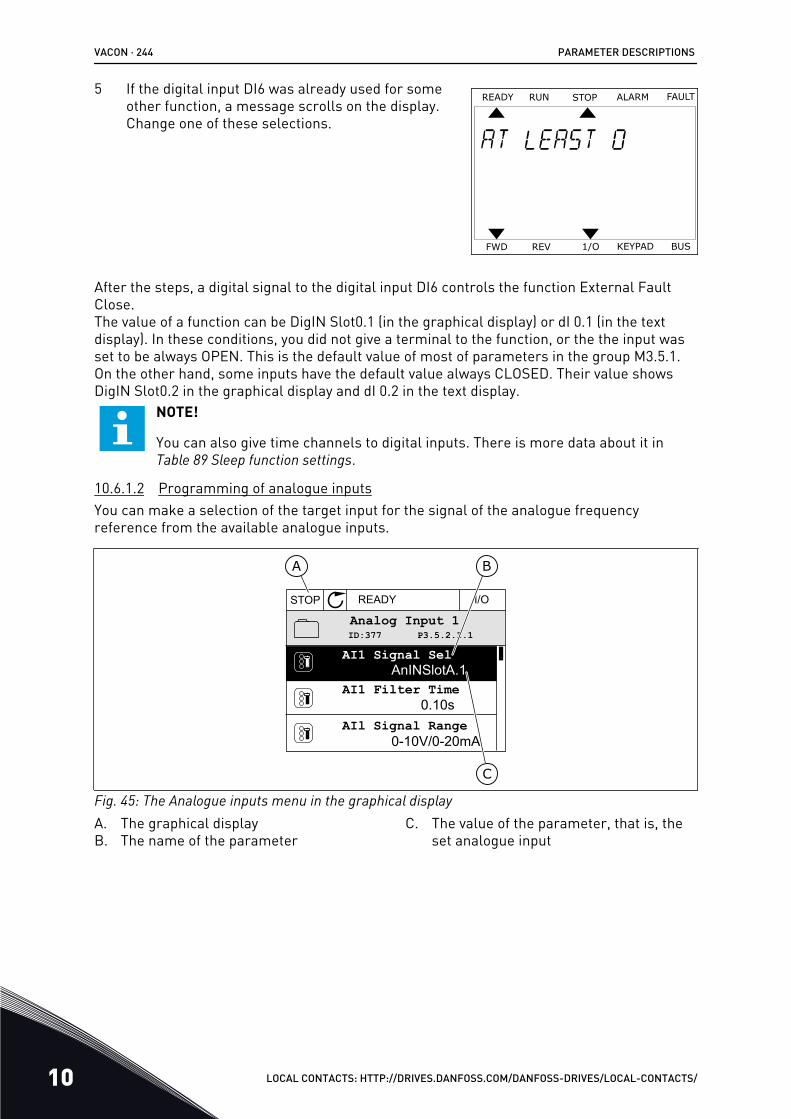
5 If the digital input DI6 was already used for someother function, a message scrolls on the display.Change one of these selections.
READY FAULTALARMSTOPRUN
KEYPAD1/OREVFWD BUS
After the steps, a digital signal to the digital input DI6 controls the function External FaultClose.The value of a function can be DigIN Slot0.1 (in the graphical display) or dI 0.1 (in the textdisplay). In these conditions, you did not give a terminal to the function, or the the input wasset to be always OPEN. This is the default value of most of parameters in the group M3.5.1.On the other hand, some inputs have the default value always CLOSED. Their value showsDigIN Slot0.2 in the graphical display and dI 0.2 in the text display.
NOTE!
You can also give time channels to digital inputs. There is more data about it inTable 89 Sleep function settings.
10.6.1.2 Programming of analogue inputsYou can make a selection of the target input for the signal of the analogue frequencyreference from the available analogue inputs.
STOP READY I/O
ID:377 P3.5.2.1.1Analog Input 1
AI1 Signal Sel
AI1 Filter TimeAnINSlotA.1
0.10s
0-10V/0-20mAAIl Signal Range
A B
C
Fig. 45: The Analogue inputs menu in the graphical displayA. The graphical displayB. The name of the parameter
C. The value of the parameter, that is, theset analogue input
VACON · 244 PARAMETER DESCRIPTIONS
10 LOCAL CONTACTS: HTTP://DRIVES.DANFOSS.COM/DANFOSS-DRIVES/LOCAL-CONTACTS/
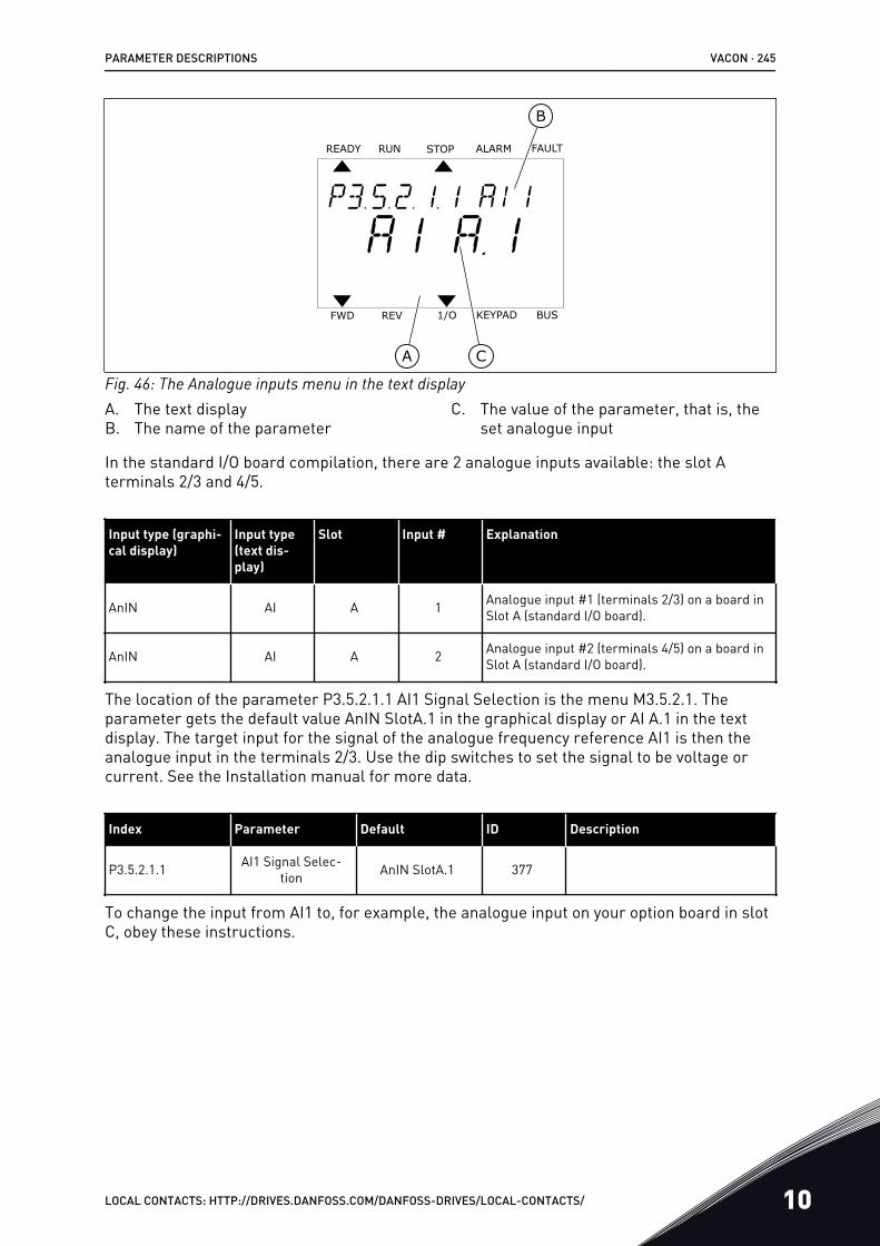
READY FAULTALARMSTOPRUN
KEYPAD1/OREVFWD BUS
A
B
C
Fig. 46: The Analogue inputs menu in the text displayA. The text displayB. The name of the parameter
C. The value of the parameter, that is, theset analogue input
In the standard I/O board compilation, there are 2 analogue inputs available: the slot Aterminals 2/3 and 4/5.
Input type (graphi-cal display)
Input type(text dis-play)
Slot Input # Explanation
AnIN AI A 1 Analogue input #1 (terminals 2/3) on a board inSlot A (standard I/O board).
AnIN AI A 2 Analogue input #2 (terminals 4/5) on a board inSlot A (standard I/O board).
The location of the parameter P3.5.2.1.1 AI1 Signal Selection is the menu M3.5.2.1. Theparameter gets the default value AnIN SlotA.1 in the graphical display or AI A.1 in the textdisplay. The target input for the signal of the analogue frequency reference AI1 is then theanalogue input in the terminals 2/3. Use the dip switches to set the signal to be voltage orcurrent. See the Installation manual for more data.
Index Parameter Default ID Description
P3.5.2.1.1 AI1 Signal Selec-tion AnIN SlotA.1 377
To change the input from AI1 to, for example, the analogue input on your option board in slotC, obey these instructions.
PARAMETER DESCRIPTIONS VACON · 245
LOCAL CONTACTS: HTTP://DRIVES.DANFOSS.COM/DANFOSS-DRIVES/LOCAL-CONTACTS/ 10
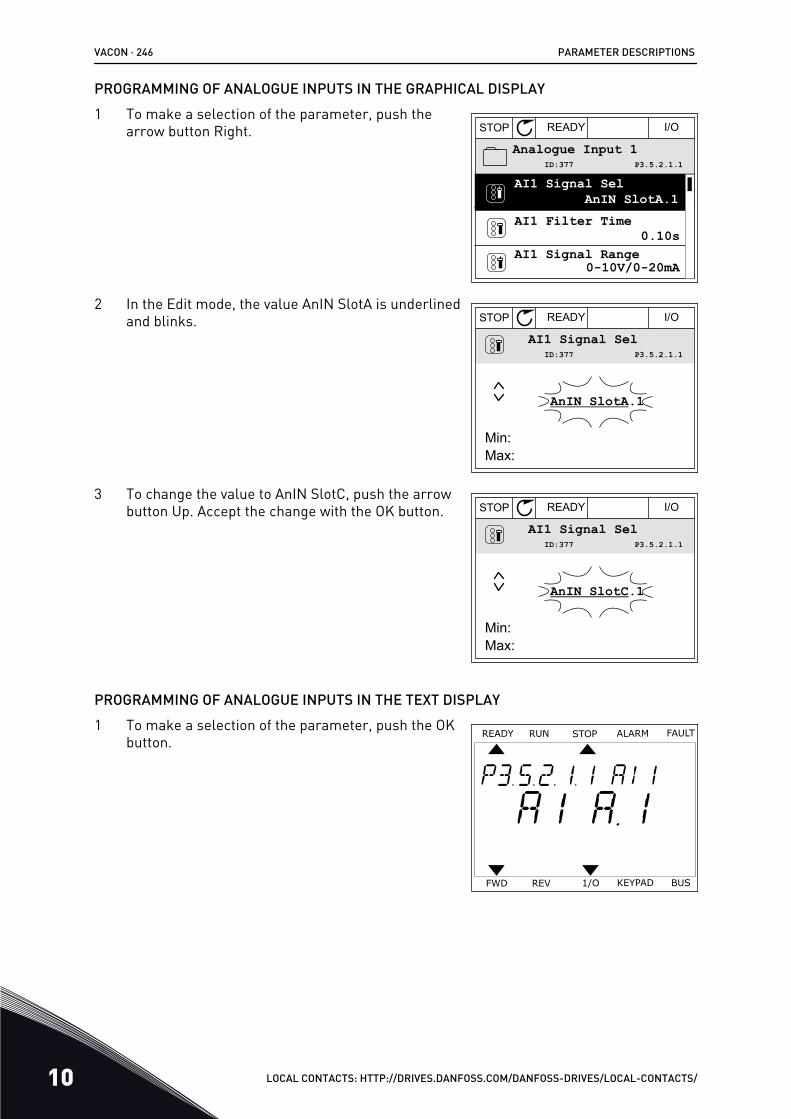
PROGRAMMING OF ANALOGUE INPUTS IN THE GRAPHICAL DISPLAY1 To make a selection of the parameter, push the
arrow button Right. STOP READY I/O
Analogue Input 1
AI1 Filter Time
AI1 Signal Range
AnIN SlotA.1
0.10s
0-10V/0-20mA
AI1 Signal SelP3.5.2.1.1ID:377
2 In the Edit mode, the value AnIN SlotA is underlinedand blinks. STOP READY I/O
AI1 Signal Sel
AnIN SlotA.1
P3.5.2.1.1ID:377
Min:Max:
3 To change the value to AnIN SlotC, push the arrowbutton Up. Accept the change with the OK button. STOP READY I/O
AI1 Signal Sel
AnIN SlotC.1
P3.5.2.1.1ID:377
Min:Max:
PROGRAMMING OF ANALOGUE INPUTS IN THE TEXT DISPLAY1 To make a selection of the parameter, push the OK
button.READY FAULTALARMSTOPRUN
KEYPAD1/OREVFWD BUS
VACON · 246 PARAMETER DESCRIPTIONS
10 LOCAL CONTACTS: HTTP://DRIVES.DANFOSS.COM/DANFOSS-DRIVES/LOCAL-CONTACTS/
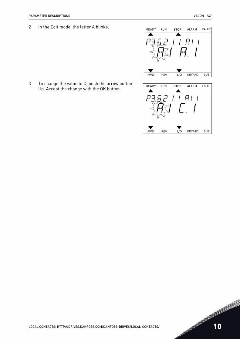
2 In the Edit mode, the letter A blinks.READY FAULTALARMSTOPRUN
KEYPAD1/OREVFWD BUS
3 To change the value to C, push the arrow buttonUp. Accept the change with the OK button.
READY FAULTALARMSTOPRUN
KEYPAD1/OREVFWD BUS
PARAMETER DESCRIPTIONS VACON · 247
LOCAL CONTACTS: HTTP://DRIVES.DANFOSS.COM/DANFOSS-DRIVES/LOCAL-CONTACTS/ 10
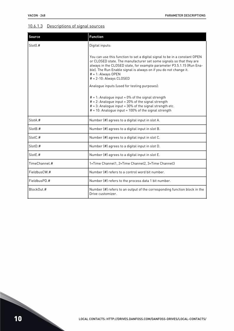
10.6.1.3 Descriptions of signal sources
Source Function
Slot0.# Digital inputs:
You can use this function to set a digital signal to be in a constant OPENor CLOSED state. The manufacturer set some signals so that they arealways in the CLOSED state, for example parameter P3.5.1.15 (Run Ena-ble). The Run Enable signal is always on if you do not change it.# = 1: Always OPEN# = 2-10: Always CLOSED
Analogue inputs (used for testing purposes):
# = 1: Analogue input = 0% of the signal strength# = 2: Analogue input = 20% of the signal strength# = 3: Analogue input = 30% of the signal strength etc.# = 10: Analogue input = 100% of the signal strength
SlotA.# Number (#) agrees to a digital input in slot A.
SlotB.# Number (#) agrees to a digital input in slot B.
SlotC.# Number (#) agrees to a digital input in slot C.
SlotD.# Number (#) agrees to a digital input in slot D.
SlotE.# Number (#) agrees to a digital input in slot E.
TimeChannel.# 1=Time Channel1, 2=Time Channel2, 3=Time Channel3
FieldbusCW.# Number (#) refers to a control word bit number.
FieldbusPD.# Number (#) refers to the process data 1 bit number.
BlockOut.# Number (#) refers to an output of the corresponding function block in theDrive customizer.
VACON · 248 PARAMETER DESCRIPTIONS
10 LOCAL CONTACTS: HTTP://DRIVES.DANFOSS.COM/DANFOSS-DRIVES/LOCAL-CONTACTS/
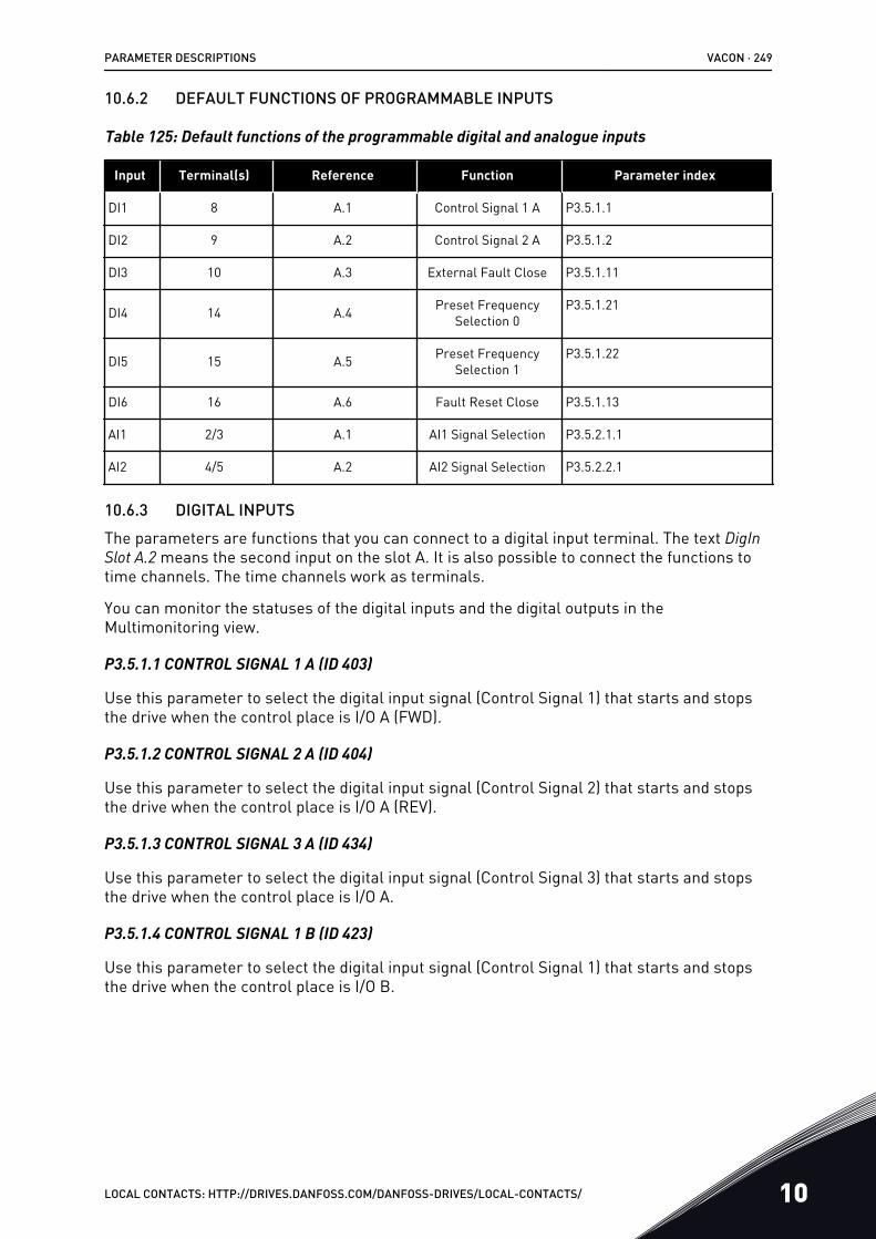
10.6.2 DEFAULT FUNCTIONS OF PROGRAMMABLE INPUTS
Table 125: Default functions of the programmable digital and analogue inputs
Input Terminal(s) Reference Function Parameter index
DI1 8 A.1 Control Signal 1 A P3.5.1.1
DI2 9 A.2 Control Signal 2 A P3.5.1.2
DI3 10 A.3 External Fault Close P3.5.1.11
DI4 14 A.4 Preset FrequencySelection 0
P3.5.1.21
DI5 15 A.5 Preset FrequencySelection 1
P3.5.1.22
DI6 16 A.6 Fault Reset Close P3.5.1.13
AI1 2/3 A.1 AI1 Signal Selection P3.5.2.1.1
AI2 4/5 A.2 AI2 Signal Selection P3.5.2.2.1
10.6.3 DIGITAL INPUTSThe parameters are functions that you can connect to a digital input terminal. The text DigInSlot A.2 means the second input on the slot A. It is also possible to connect the functions totime channels. The time channels work as terminals.
You can monitor the statuses of the digital inputs and the digital outputs in theMultimonitoring view.
P3.5.1.1 CONTROL SIGNAL 1 A (ID 403)
Use this parameter to select the digital input signal (Control Signal 1) that starts and stopsthe drive when the control place is I/O A (FWD).
P3.5.1.2 CONTROL SIGNAL 2 A (ID 404)
Use this parameter to select the digital input signal (Control Signal 2) that starts and stopsthe drive when the control place is I/O A (REV).
P3.5.1.3 CONTROL SIGNAL 3 A (ID 434)
Use this parameter to select the digital input signal (Control Signal 3) that starts and stopsthe drive when the control place is I/O A.
P3.5.1.4 CONTROL SIGNAL 1 B (ID 423)
Use this parameter to select the digital input signal (Control Signal 1) that starts and stopsthe drive when the control place is I/O B.
PARAMETER DESCRIPTIONS VACON · 249
LOCAL CONTACTS: HTTP://DRIVES.DANFOSS.COM/DANFOSS-DRIVES/LOCAL-CONTACTS/ 10
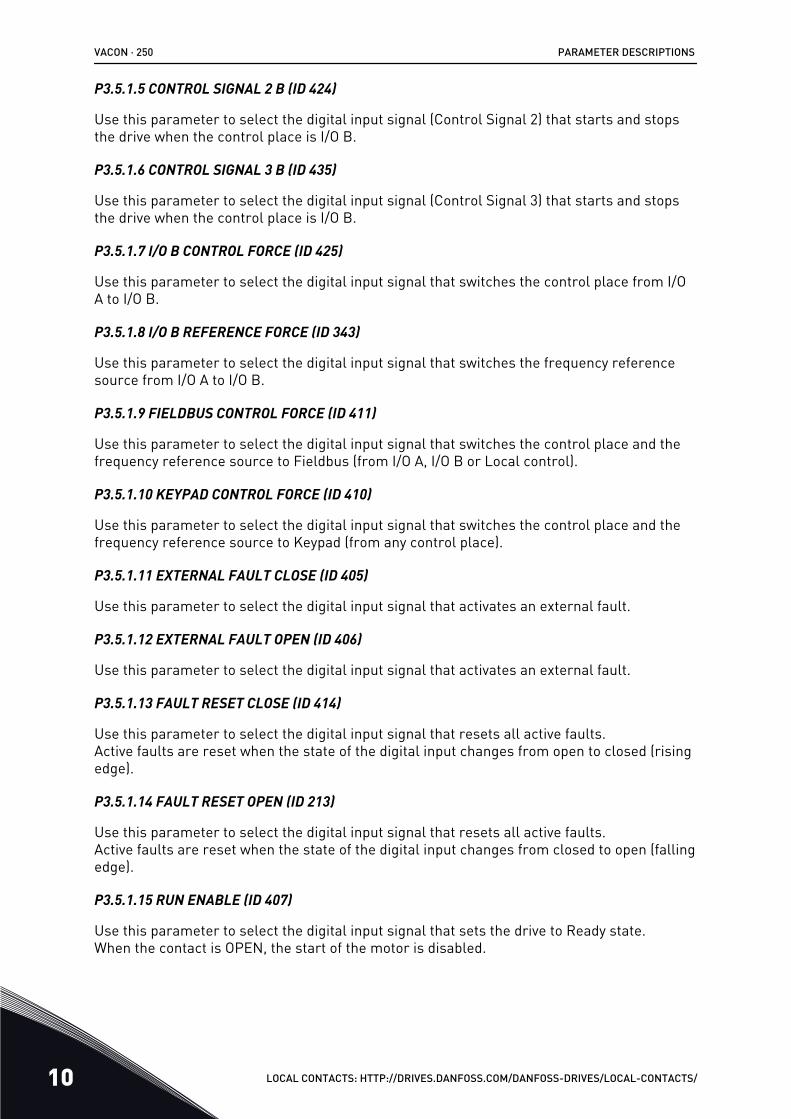
P3.5.1.5 CONTROL SIGNAL 2 B (ID 424)
Use this parameter to select the digital input signal (Control Signal 2) that starts and stopsthe drive when the control place is I/O B.
P3.5.1.6 CONTROL SIGNAL 3 B (ID 435)
Use this parameter to select the digital input signal (Control Signal 3) that starts and stopsthe drive when the control place is I/O B.
P3.5.1.7 I/O B CONTROL FORCE (ID 425)
Use this parameter to select the digital input signal that switches the control place from I/OA to I/O B.
P3.5.1.8 I/O B REFERENCE FORCE (ID 343)
Use this parameter to select the digital input signal that switches the frequency referencesource from I/O A to I/O B.
P3.5.1.9 FIELDBUS CONTROL FORCE (ID 411)
Use this parameter to select the digital input signal that switches the control place and thefrequency reference source to Fieldbus (from I/O A, I/O B or Local control).
P3.5.1.10 KEYPAD CONTROL FORCE (ID 410)
Use this parameter to select the digital input signal that switches the control place and thefrequency reference source to Keypad (from any control place).
P3.5.1.11 EXTERNAL FAULT CLOSE (ID 405)
Use this parameter to select the digital input signal that activates an external fault.
P3.5.1.12 EXTERNAL FAULT OPEN (ID 406)
Use this parameter to select the digital input signal that activates an external fault.
P3.5.1.13 FAULT RESET CLOSE (ID 414)
Use this parameter to select the digital input signal that resets all active faults.Active faults are reset when the state of the digital input changes from open to closed (risingedge).
P3.5.1.14 FAULT RESET OPEN (ID 213)
Use this parameter to select the digital input signal that resets all active faults.Active faults are reset when the state of the digital input changes from closed to open (fallingedge).
P3.5.1.15 RUN ENABLE (ID 407)
Use this parameter to select the digital input signal that sets the drive to Ready state.When the contact is OPEN, the start of the motor is disabled.
VACON · 250 PARAMETER DESCRIPTIONS
10 LOCAL CONTACTS: HTTP://DRIVES.DANFOSS.COM/DANFOSS-DRIVES/LOCAL-CONTACTS/
When the contact is CLOSED, the start of the motor is enabled.
NOTE!
The state of the drive remains in 'Not Ready' if the state of this signal is 'opened'.If the Run Enable signal is used for stopping the drive, the drive will always coast tostop regardless of the selection in parameter P3.2.5 Stop Function.
P3.5.1.16 RUN INTERLOCK 1 (ID 1041)
Use this parameter to select the digital input signal that prevents to start the drive.The drive can be ready but start is not possible when the state of the interlock signal is 'open'(damper interlock).
P3.5.1.17 RUN INTERLOCK 2 (ID 1042)
Use this parameter to select the digital input signal that prevents to start the drive.The drive can be ready but start is not possible when the state of the interlock signal is 'open'(damper interlock).
If an interlock is active, the drive cannot start.
You can use this function to prevent the start of the drive when the damper is closed. If youactivate an interlock during the operation of the drive, the drive stops.
P3.5.1.18 MOTOR PREHEAT ON (ID 1044)
Use this parameter to select the digital input signal that activates Motor Preheat function.The Motor Preheat function feeds DC-current to the motor when the drive is in the stop state.
P3.5.1.19 RAMP 2 SELECTION (ID 408)
Use this parameter to select the digital input signal that selects the ramp time to be used.
P3.5.1.20 ACC/DEC PROHIBIT (ID 415)
Use this parameter to select the digital input signal that prevents the acceleration and thedeceleration of the drive.No acceleration or deceleration is possible until the contact is open.
P3.5.1.21 PRESET FREQUENCY SELECTION 0 (ID 419)
Use this parameter to set the digital input signal that selects the preset frequencies.
P3.5.1.22 PRESET FREQUENCY SELECTION 1 (ID 420)
Use this parameter to set the digital input signal that selects the preset frequencies.
P3.5.1.23 PRESET FREQUENCY SELECTION 2 (ID 421)
Use this parameter to set the digital input signal that selects the preset frequencies.
PARAMETER DESCRIPTIONS VACON · 251
LOCAL CONTACTS: HTTP://DRIVES.DANFOSS.COM/DANFOSS-DRIVES/LOCAL-CONTACTS/ 10
P3.5.1.24 MOTOR POTENTIOMETER UP (ID 418)
Use this parameter to increase the output frequency with a digital input signal.The motor potentiometer reference INCREASES until the contact is open.
P3.5.1.25 MOTOR POTENTIOMETER DOWN (ID 417)
Use this parameter to decrease the output frequency with a digital input signal.The motor potentiometer reference DECREASES until the contact is open.
P3.5.1.26 QUICK STOP ACTIVATION (ID 1213)
Use this parameter to select the digital input signal that activates a Quick Stop function. TheQuick Stop function stops the drive regardless of the control place or the state of the controlsignals.
P3.5.1.27 TIMER 1 (ID 447)
Use this parameter to select the digital input signal that starts the timer.The timer starts when this signal is deactivated (falling edge). The output is deactivated whenthe time defined in the duration parameter has elapsed.
P3.5.1.28 TIMER 2 (ID 448)
Use this parameter to select the digital input signal that starts the timer.The timer starts when this signal is deactivated (falling edge). The output is deactivated whenthe time defined in the duration parameter has elapsed.
P3.5.1.29 TIMER 3 (ID 449)
Use this parameter to select the digital input signal that starts the timer.The timer starts when this signal is deactivated (falling edge). The output is deactivated whenthe time defined in the duration parameter has elapsed.
P3.5.1.30 PID SETPOINT BOOST (ID 1046)
Use this parameter to select the digital input signal that activates the boost for the PIDsetpoint value.The timer starts when this signal is deactivated (falling edge). The output is deactivated whenthe time defined in the duration parameter has elapsed.
P3.5.1.31 PID SETPOINT SELECTION (ID 1047)
Use this parameter to set the digital input signal that selects the PID setpoint value to beused.
P3.5.1.32 EXTERNAL PID START SIGNAL (ID 1049)
Use this parameter to select the digital input signal that starts and stops the external PIDcontroller.
VACON · 252 PARAMETER DESCRIPTIONS
10 LOCAL CONTACTS: HTTP://DRIVES.DANFOSS.COM/DANFOSS-DRIVES/LOCAL-CONTACTS/
NOTE!
This parameter has no effect if the external PID controller is not enabled in Group3.14.
P3.5.1.33 EXTERNAL PID SETPOINT SELECTION (ID 1048)
Use this parameter to set the digital input signal that selects the PID setpoint value to beused.
P3.5.1.34 MOTOR 1 INTERLOCK (ID 426)
Use this parameter to select the digital input signal that is used as interlock signal for theMulti-Pump system.
P3.5.1.35 MOTOR 2 INTERLOCK (ID 427)
Use this parameter to select the digital input signal that is used as interlock signal for theMulti-Pump system.
P3.5.1.36 MOTOR 3 INTERLOCK (ID 428)
Use this parameter to select the digital input signal that is used as interlock signal for theMulti-Pump system.
P3.5.1.37 MOTOR 4 INTERLOCK (ID 429)
Use this parameter to select the digital input signal that is used as interlock signal for theMulti-Pump system.
P3.5.1.38 MOTOR 5 INTERLOCK (ID 430)
Use this parameter to select the digital input signal that is used as interlock signal for theMulti-Pump system.
P3.5.1.39 MOTOR 6 INTERLOCK (ID 486)
Use this parameter to select the digital input signal that is used as interlock signal for theMulti-Pump system.
P3.5.1.40 RESET MAINTENANCE COUNTER (ID 490)
Use this parameter to select the digital input that reset the value of the MaintenanceCounter.
P3.5.1.41 ENABLE DI JOGGING (ID 532)
Use this parameter to enable the jogging commands from digital inputs.This parameter has no effect on the jogging from fieldbus.
P3.5.1.42 JOGGING REFERENCE 1 ACTIVATION (ID 530)
Use this parameter to set the digital input signals that activate the Jogging function.
PARAMETER DESCRIPTIONS VACON · 253
LOCAL CONTACTS: HTTP://DRIVES.DANFOSS.COM/DANFOSS-DRIVES/LOCAL-CONTACTS/ 10
NOTE!
If the input is activated, the drive starts.
P3.5.1.43 JOGGING REFERENCE 2 ACTIVATION (ID 531)
Use this parameter to set the digital input signals that activate the Jogging function.
NOTE!
If the input is activated, the drive starts.
P3.5.1.44 MECHANICAL BRAKE FEEDBACK (ID 1210)
Use this parameter to set the brake status feedback signal from mechanical brake.Connect this input signal to the auxiliary contact of the mechanical brake. If the contact is notclosed within the given time, the drive shows a fault.
P3.5.1.45 FIRE MODE ACTIVATION OPEN (ID 1596)
Use this parameter to select the digital input signal that activates the Fire Mode function.This parameter activates the Fire Mode if it is enabled with a correct password.
P3.5.1.46 FIRE MODE ACTIVATION CLOSE (ID 1619)
Use this parameter to select the digital input signal that activates the Fire Mode function.This parameter activates the Fire Mode if it is enabled with a correct password.
P3.5.1.47 FIRE MODE REVERSE (ID 1618)
Use this parameter to select the digital input signal that gives a command for reverserotation direction during the Fire Mode.This function has no effect in normal operation.
P3.5.1.48 AUTO-CLEANING ACTIVATION (ID 1715)
Use this parameter to select the digital input signal that starts the Auto-cleaning.The Auto-cleaning stops if the activation signal is removed before the process is complete.
NOTE!
If the input is activated, the drive starts.
P3.5.1.49 PARAMETER SET 1/2 SELECTION (ID 496)
Use this parameter to set the digital input that selects the parameter set to be used.This function is enabled if any other slot than ‘DigIN Slot0’ is selected to this parameter. Theparameter set selection is allowed only when the drive is stopped.
Contact Open = Parameter Set 1 is loaded as the active setContact Closed = Parameter Set 2 is loaded as the active set
VACON · 254 PARAMETER DESCRIPTIONS
10 LOCAL CONTACTS: HTTP://DRIVES.DANFOSS.COM/DANFOSS-DRIVES/LOCAL-CONTACTS/
NOTE!
Parameter values are stored to Set 1 and Set 2 by parameters B6.5.4 Save to Set 1and B6.5.4 Save to Set 2. These parameters can be used either from keypad orVACON® Live PC tool.
P3.5.1.50 (P3.9.9.1) USER DEFINED FAULT 1 ACTIVATION (ID 15523)
Use this parameter to set the digital input signal that activates User Defined Fault 1 (Fault ID1114).
P3.5.1.51 (P3.9.10.1) USER DEFINED FAULT 2 ACTIVATION (ID 15524)
Use this parameter to set the digital input signal that activates User Defined Fault 2 (Fault ID1115).
10.6.4 ANALOGUE INPUTS
P3.5.2.1.1 AI1 SIGNAL SELECTION (ID 377)
Use this parameter to connect the AI signal to the analogue input of your choice.This parameter is programmable. See Table 125 Default functions of the programmable digital and analogue inputs.
P3.5.2.1.2 AI1 SIGNAL FILTER TIME (ID 378)
Use this parameter to filter out disturbances in the analogue input signal.To activate this parameter, enter a value greater than 0.
NOTE!
A long filter time makes the regulation response slow.
PARAMETER DESCRIPTIONS VACON · 255
LOCAL CONTACTS: HTTP://DRIVES.DANFOSS.COM/DANFOSS-DRIVES/LOCAL-CONTACTS/ 10
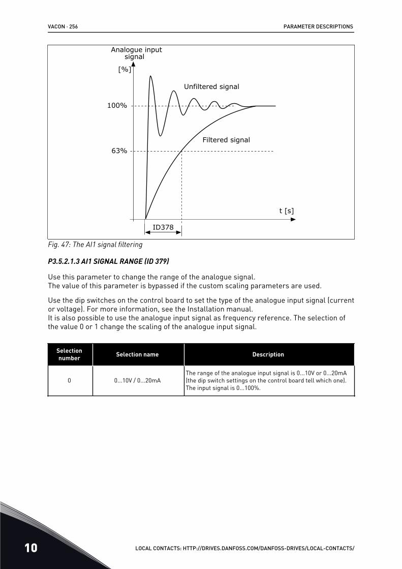
[%]
100%
63%
ID378
t [s]
Filtered signal
Unfiltered signal
Analogue inputsignal
Fig. 47: The AI1 signal filtering
P3.5.2.1.3 AI1 SIGNAL RANGE (ID 379)
Use this parameter to change the range of the analogue signal.The value of this parameter is bypassed if the custom scaling parameters are used.
Use the dip switches on the control board to set the type of the analogue input signal (currentor voltage). For more information, see the Installation manual.It is also possible to use the analogue input signal as frequency reference. The selection ofthe value 0 or 1 change the scaling of the analogue input signal.
Selectionnumber Selection name Description
0 0...10V / 0...20mAThe range of the analogue input signal is 0...10V or 0...20mA(the dip switch settings on the control board tell which one).The input signal is 0...100%.
VACON · 256 PARAMETER DESCRIPTIONS
10 LOCAL CONTACTS: HTTP://DRIVES.DANFOSS.COM/DANFOSS-DRIVES/LOCAL-CONTACTS/
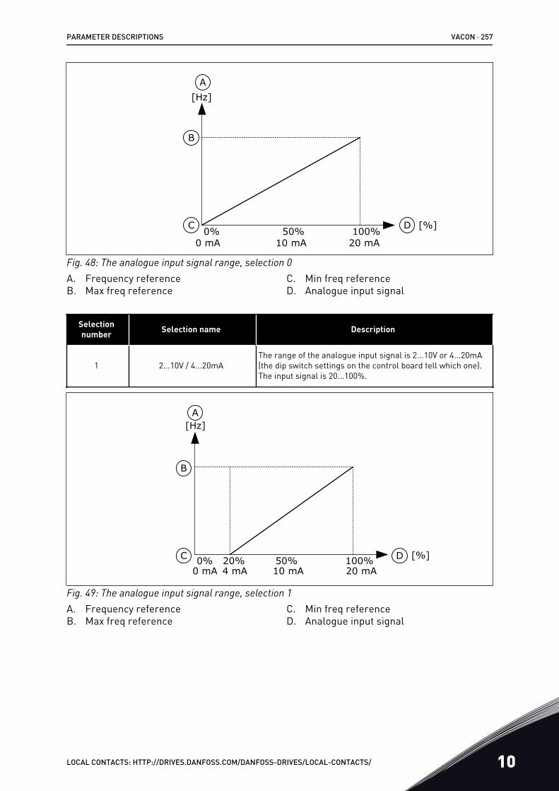
0% 100%50%C
B
A
D
0 mA 20 mA10 mA
[Hz]
[%]
Fig. 48: The analogue input signal range, selection 0A. Frequency referenceB. Max freq reference
C. Min freq referenceD. Analogue input signal
Selectionnumber Selection name Description
1 2...10V / 4...20mAThe range of the analogue input signal is 2...10V or 4...20mA(the dip switch settings on the control board tell which one).The input signal is 20...100%.
0% 100%50%20%C
B
A
D
[Hz]
[%]0 mA 20 mA10 mA4 mA
Fig. 49: The analogue input signal range, selection 1A. Frequency referenceB. Max freq reference
C. Min freq referenceD. Analogue input signal
PARAMETER DESCRIPTIONS VACON · 257
LOCAL CONTACTS: HTTP://DRIVES.DANFOSS.COM/DANFOSS-DRIVES/LOCAL-CONTACTS/ 10
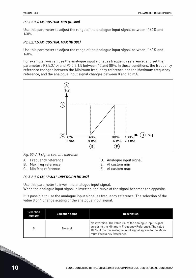
P3.5.2.1.4 AI1 CUSTOM. MIN (ID 380)
Use this parameter to adjust the range of the analogue input signal between -160% and160%.
P3.5.2.1.5 AI1 CUSTOM. MAX (ID 381)
Use this parameter to adjust the range of the analogue input signal between -160% and160%.
For example, you can use the analogue input signal as frequency reference, and set theparameters P3.5.2.1.4 and P3.5.2.1.5 between 40 and 80%. In these conditions, the frequencyreference changes between the Minimum frequency reference and the Maximum frequencyreference, and the analogue input signal changes between 8 and 16 mA.
0% 100%80%40%C
B
A
D
E F
0 mA 20 mA16 mA8 mA
[Hz]
[%]
Fig. 50: AI1 signal custom. min/maxA. Frequency referenceB. Max freq referenceC. Min freq reference
D. Analogue input signalE. AI custom minF. AI custom max
P3.5.2.1.6 AI1 SIGNAL INVERSION (ID 387)
Use this parameter to invert the analogue input signal.When the analogue input signal is inverted, the curve of the signal becomes the opposite.
It is possible to use the analogue input signal as frequency reference. The selection of thevalue 0 or 1 change scaling of the analogue input signal.
Selectionnumber Selection name Description
0 Normal
No inversion. The value 0% of the analogue input signalagrees to the Minimum Frequency Reference. The value100% of the the analogue input signal agrees to the Maxi-mum Frequency Reference.
VACON · 258 PARAMETER DESCRIPTIONS
10 LOCAL CONTACTS: HTTP://DRIVES.DANFOSS.COM/DANFOSS-DRIVES/LOCAL-CONTACTS/

0% 100%50%C
B
A
D
[Hz]
[%]
0 mA 20 mA10 mA
Fig. 51: AI1 signal inversion, selection 0A. Frequency referenceB. Max freq reference
C. Min freq referenceD. Analogue input signal
Selectionnumber Selection name Description
1 Inverted
Signal inversion. The value 0% of the analogue input signalagrees to the Maximum Frequency Reference. The value100% of the analogue input signal agrees to the MinimumFrequency Reference.
0% 100%50%C
B
A
D
[Hz]
[%]0 mA 20 mA10 mA
Fig. 52: AI1 signal inversion, selection 1A. Frequency referenceB. Max freq reference
C. Min freq referenceD. Analogue input signal
PARAMETER DESCRIPTIONS VACON · 259
LOCAL CONTACTS: HTTP://DRIVES.DANFOSS.COM/DANFOSS-DRIVES/LOCAL-CONTACTS/ 10

10.6.5 DIGITAL OUTPUTS
P3.5.3.2.1 RO1 FUNCTION (ID 11001)
Use this parameter to select a function or a signal that is connected to the relay output.
VACON · 260 PARAMETER DESCRIPTIONS
10 LOCAL CONTACTS: HTTP://DRIVES.DANFOSS.COM/DANFOSS-DRIVES/LOCAL-CONTACTS/
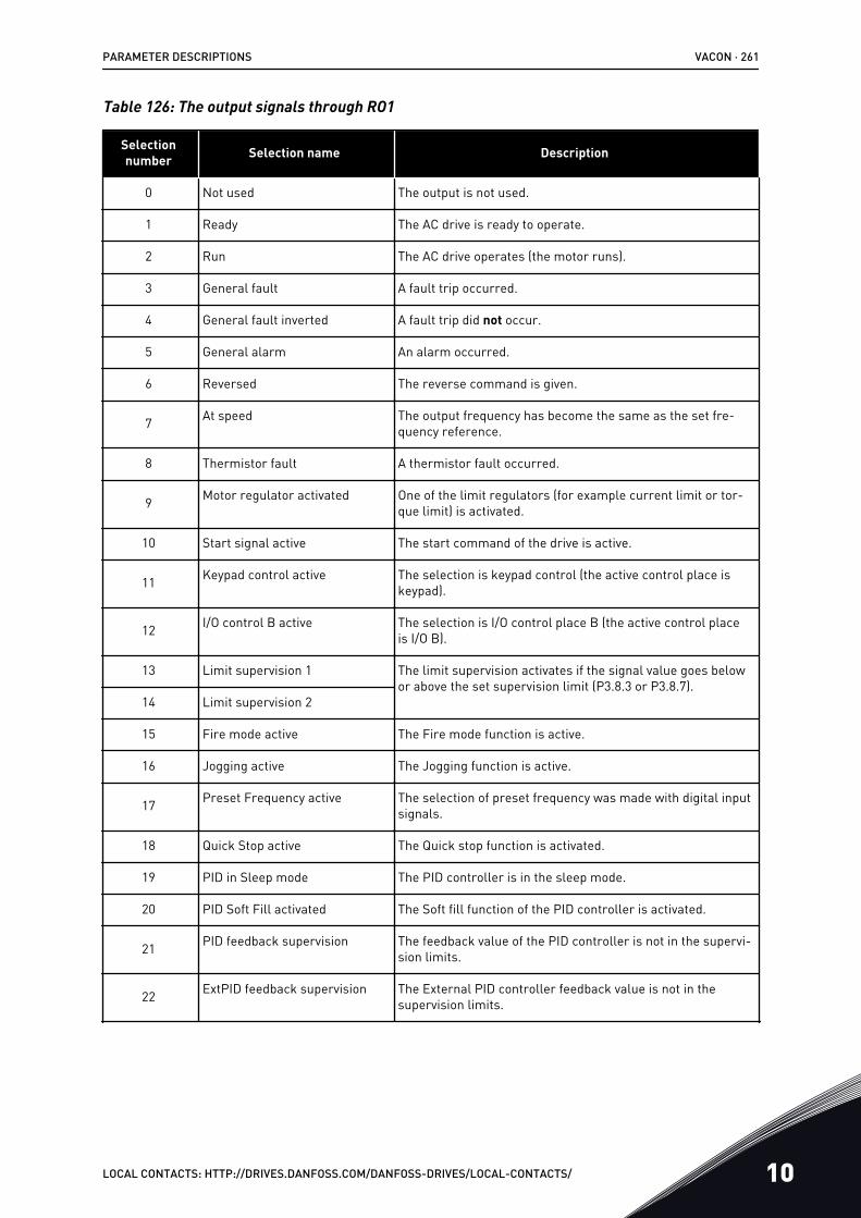
Table 126: The output signals through RO1
Selectionnumber Selection name Description
0 Not used The output is not used.
1 Ready The AC drive is ready to operate.
2 Run The AC drive operates (the motor runs).
3 General fault A fault trip occurred.
4 General fault inverted A fault trip did not occur.
5 General alarm An alarm occurred.
6 Reversed The reverse command is given.
7 At speed The output frequency has become the same as the set fre-quency reference.
8 Thermistor fault A thermistor fault occurred.
9 Motor regulator activated One of the limit regulators (for example current limit or tor-que limit) is activated.
10 Start signal active The start command of the drive is active.
11 Keypad control active The selection is keypad control (the active control place iskeypad).
12 I/O control B active The selection is I/O control place B (the active control placeis I/O B).
13 Limit supervision 1 The limit supervision activates if the signal value goes belowor above the set supervision limit (P3.8.3 or P3.8.7).
14 Limit supervision 2
15 Fire mode active The Fire mode function is active.
16 Jogging active The Jogging function is active.
17 Preset Frequency active The selection of preset frequency was made with digital inputsignals.
18 Quick Stop active The Quick stop function is activated.
19 PID in Sleep mode The PID controller is in the sleep mode.
20 PID Soft Fill activated The Soft fill function of the PID controller is activated.
21 PID feedback supervision The feedback value of the PID controller is not in the supervi-sion limits.
22 ExtPID feedback supervision The External PID controller feedback value is not in thesupervision limits.
PARAMETER DESCRIPTIONS VACON · 261
LOCAL CONTACTS: HTTP://DRIVES.DANFOSS.COM/DANFOSS-DRIVES/LOCAL-CONTACTS/ 10
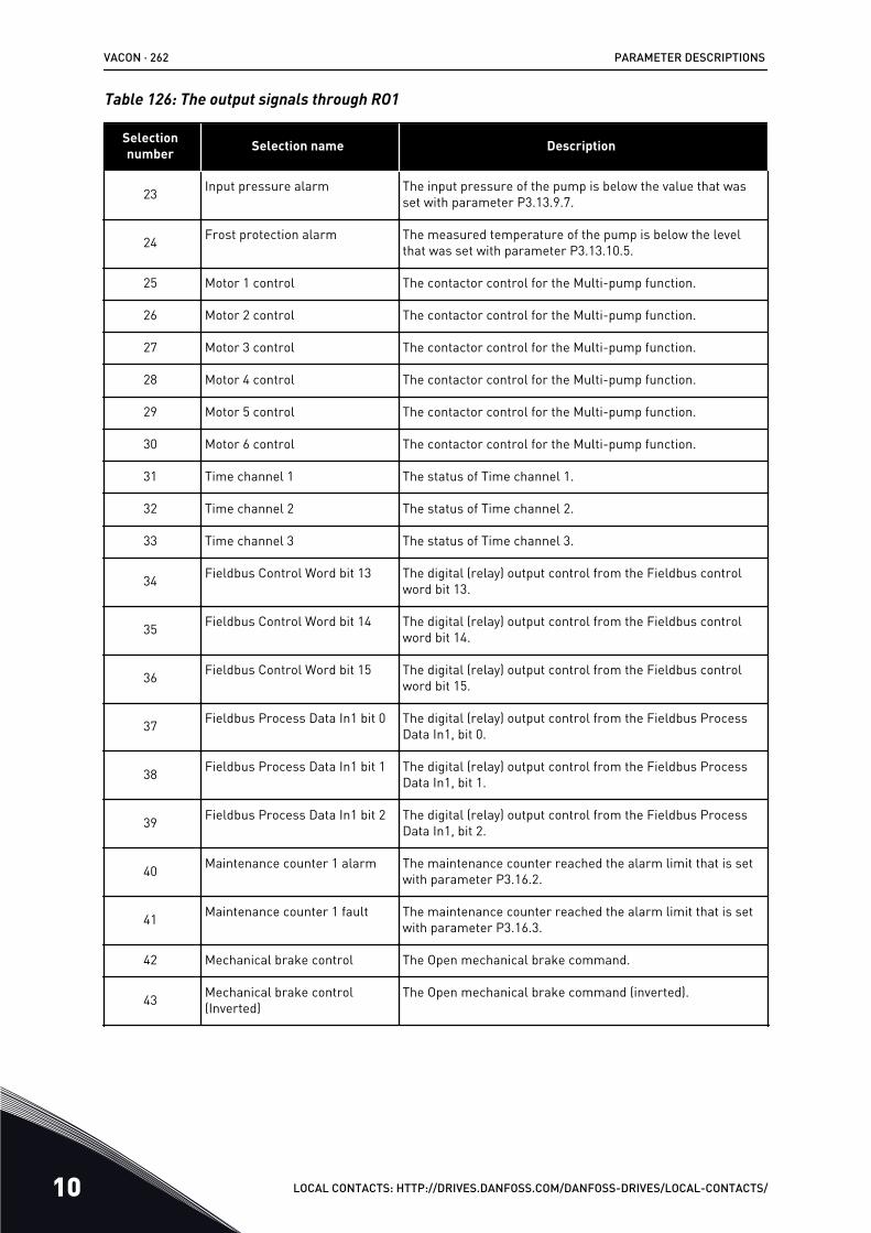
Table 126: The output signals through RO1
Selectionnumber Selection name Description
23 Input pressure alarm The input pressure of the pump is below the value that wasset with parameter P3.13.9.7.
24 Frost protection alarm The measured temperature of the pump is below the levelthat was set with parameter P3.13.10.5.
25 Motor 1 control The contactor control for the Multi-pump function.
26 Motor 2 control The contactor control for the Multi-pump function.
27 Motor 3 control The contactor control for the Multi-pump function.
28 Motor 4 control The contactor control for the Multi-pump function.
29 Motor 5 control The contactor control for the Multi-pump function.
30 Motor 6 control The contactor control for the Multi-pump function.
31 Time channel 1 The status of Time channel 1.
32 Time channel 2 The status of Time channel 2.
33 Time channel 3 The status of Time channel 3.
34 Fieldbus Control Word bit 13 The digital (relay) output control from the Fieldbus controlword bit 13.
35 Fieldbus Control Word bit 14 The digital (relay) output control from the Fieldbus controlword bit 14.
36 Fieldbus Control Word bit 15 The digital (relay) output control from the Fieldbus controlword bit 15.
37 Fieldbus Process Data In1 bit 0 The digital (relay) output control from the Fieldbus ProcessData In1, bit 0.
38 Fieldbus Process Data In1 bit 1 The digital (relay) output control from the Fieldbus ProcessData In1, bit 1.
39 Fieldbus Process Data In1 bit 2 The digital (relay) output control from the Fieldbus ProcessData In1, bit 2.
40 Maintenance counter 1 alarm The maintenance counter reached the alarm limit that is setwith parameter P3.16.2.
41 Maintenance counter 1 fault The maintenance counter reached the alarm limit that is setwith parameter P3.16.3.
42 Mechanical brake control The Open mechanical brake command.
43 Mechanical brake control(Inverted)
The Open mechanical brake command (inverted).
VACON · 262 PARAMETER DESCRIPTIONS
10 LOCAL CONTACTS: HTTP://DRIVES.DANFOSS.COM/DANFOSS-DRIVES/LOCAL-CONTACTS/
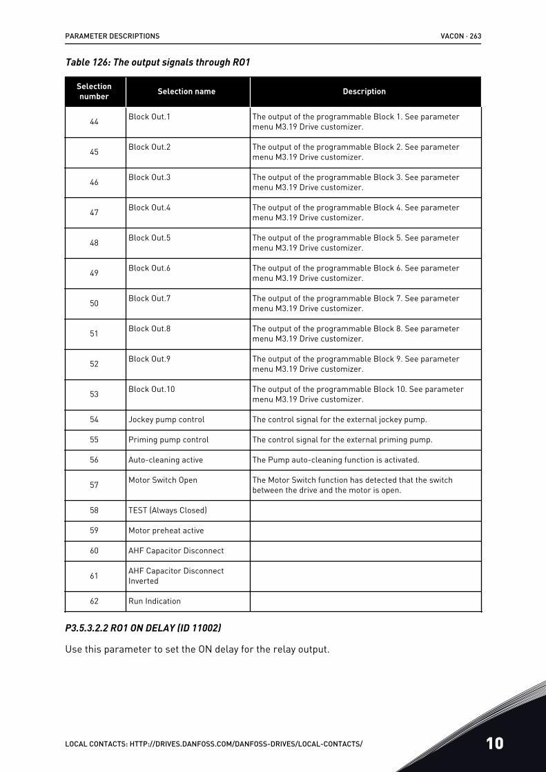
Table 126: The output signals through RO1
Selectionnumber Selection name Description
44 Block Out.1 The output of the programmable Block 1. See parametermenu M3.19 Drive customizer.
45 Block Out.2 The output of the programmable Block 2. See parametermenu M3.19 Drive customizer.
46 Block Out.3 The output of the programmable Block 3. See parametermenu M3.19 Drive customizer.
47 Block Out.4 The output of the programmable Block 4. See parametermenu M3.19 Drive customizer.
48 Block Out.5 The output of the programmable Block 5. See parametermenu M3.19 Drive customizer.
49 Block Out.6 The output of the programmable Block 6. See parametermenu M3.19 Drive customizer.
50 Block Out.7 The output of the programmable Block 7. See parametermenu M3.19 Drive customizer.
51 Block Out.8 The output of the programmable Block 8. See parametermenu M3.19 Drive customizer.
52 Block Out.9 The output of the programmable Block 9. See parametermenu M3.19 Drive customizer.
53 Block Out.10 The output of the programmable Block 10. See parametermenu M3.19 Drive customizer.
54 Jockey pump control The control signal for the external jockey pump.
55 Priming pump control The control signal for the external priming pump.
56 Auto-cleaning active The Pump auto-cleaning function is activated.
57 Motor Switch Open The Motor Switch function has detected that the switchbetween the drive and the motor is open.
58 TEST (Always Closed)
59 Motor preheat active
60 AHF Capacitor Disconnect
61 AHF Capacitor DisconnectInverted
62 Run Indication
P3.5.3.2.2 RO1 ON DELAY (ID 11002)
Use this parameter to set the ON delay for the relay output.
PARAMETER DESCRIPTIONS VACON · 263
LOCAL CONTACTS: HTTP://DRIVES.DANFOSS.COM/DANFOSS-DRIVES/LOCAL-CONTACTS/ 10

P3.5.3.2.3 RO1 OFF DELAY (ID 11003)
Use this parameter to set the OFF delay for the relay output.
10.6.6 ANALOGUE OUTPUTS
P3.5.4.1.1 AO1 FUNCTION (ID 10050)
Use this parameter to select a function or a signal that is connected to the analogue output.The contents of the analogue output signal 1 are specified in this parameter. The scaling ofthe analogue output signal depends on the signal.
VACON · 264 PARAMETER DESCRIPTIONS
10 LOCAL CONTACTS: HTTP://DRIVES.DANFOSS.COM/DANFOSS-DRIVES/LOCAL-CONTACTS/
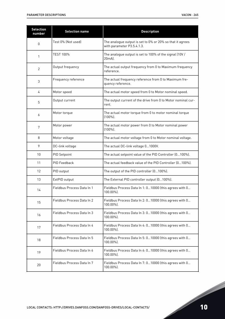
Selectionnumber Selection name Description
0 Test 0% (Not used) The analogue output is set to 0% or 20% so that it agreeswith parameter P3.5.4.1.3.
1 TEST 100% The analogue output is set to 100% of the signal (10V /20mA).
2 Output frequency The actual output frequency from 0 to Maximum frequencyreference.
3 Frequency reference The actual frequency reference from 0 to Maximum fre-quency reference.
4 Motor speed The actual motor speed from 0 to Motor nominal speed.
5 Output current The output current of the drive from 0 to Motor nominal cur-rent.
6 Motor torque The actual motor torque from 0 to motor nominal torque(100%).
7 Motor power The actual motor power from 0 to Motor nominal power(100%).
8 Motor voltage The actual motor voltage from 0 to Motor nominal voltage.
9 DC-link voltage The actual DC-link voltage 0…1000V.
10 PID Setpoint The actual setpoint value of the PID Controller (0…100%).
11 PID Feedback The actual feedback value of the PID Controller (0…100%).
12 PID output The output of the PID controller (0…100%).
13 ExtPID output The External PID controller output (0…100%).
14 Fieldbus Process Data In 1 Fieldbus Process Data In 1: 0…10000 (this agrees with 0…100.00%).
15 Fieldbus Process Data In 2 Fieldbus Process Data In 2: 0…10000 (this agrees with 0…100.00%).
16 Fieldbus Process Data In 3 Fieldbus Process Data In 3: 0…10000 (this agrees with 0…100.00%).
17 Fieldbus Process Data In 4 Fieldbus Process Data In 4: 0…10000 (this agrees with 0…100.00%).
18 Fieldbus Process Data In 5 Fieldbus Process Data In 5: 0…10000 (this agrees with 0…100.00%).
19 Fieldbus Process Data In 6 Fieldbus Process Data In 6: 0…10000 (this agrees with 0…100.00%).
20 Fieldbus Process Data In 7 Fieldbus Process Data In 7: 0…10000 (this agrees with 0…100.00%).
PARAMETER DESCRIPTIONS VACON · 265
LOCAL CONTACTS: HTTP://DRIVES.DANFOSS.COM/DANFOSS-DRIVES/LOCAL-CONTACTS/ 10
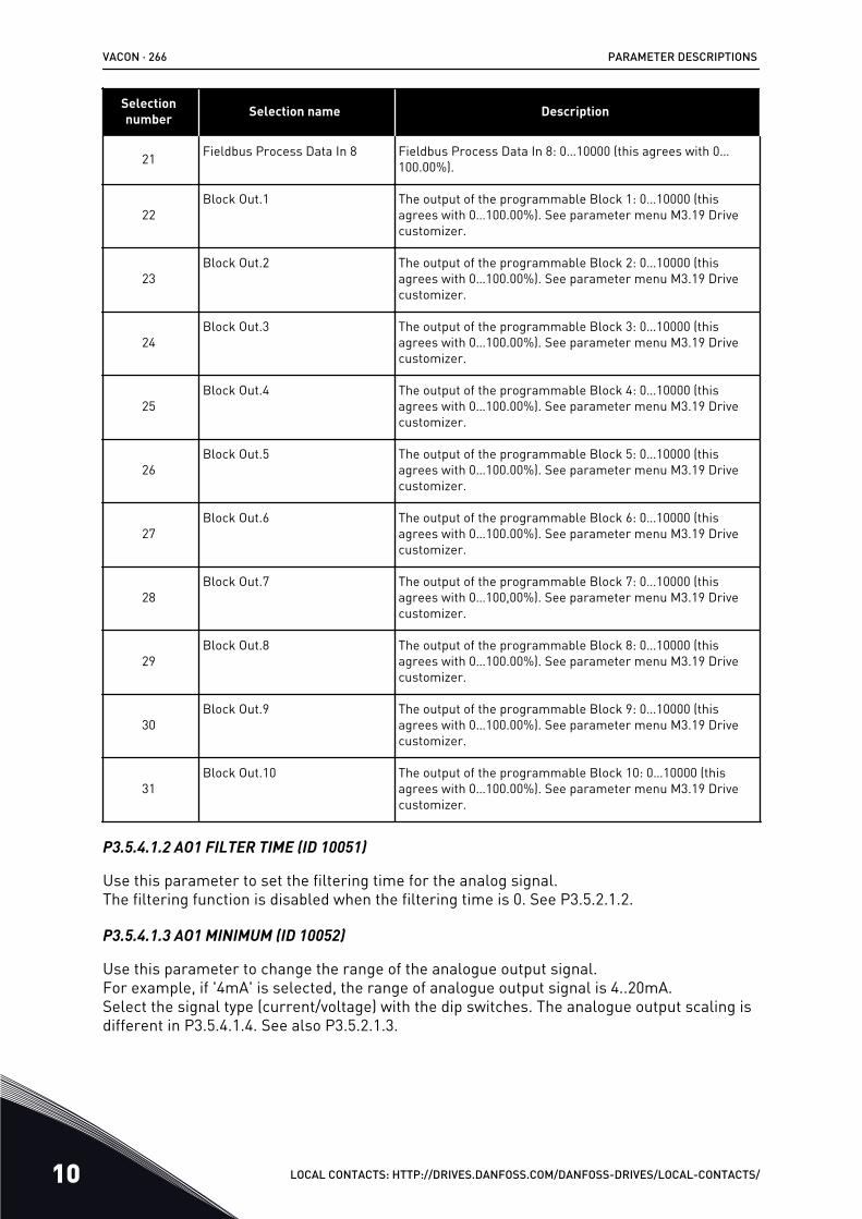
Selectionnumber Selection name Description
21 Fieldbus Process Data In 8 Fieldbus Process Data In 8: 0…10000 (this agrees with 0…100.00%).
22Block Out.1 The output of the programmable Block 1: 0…10000 (this
agrees with 0…100.00%). See parameter menu M3.19 Drivecustomizer.
23Block Out.2 The output of the programmable Block 2: 0…10000 (this
agrees with 0…100.00%). See parameter menu M3.19 Drivecustomizer.
24Block Out.3 The output of the programmable Block 3: 0…10000 (this
agrees with 0…100.00%). See parameter menu M3.19 Drivecustomizer.
25Block Out.4 The output of the programmable Block 4: 0…10000 (this
agrees with 0…100.00%). See parameter menu M3.19 Drivecustomizer.
26Block Out.5 The output of the programmable Block 5: 0…10000 (this
agrees with 0…100.00%). See parameter menu M3.19 Drivecustomizer.
27Block Out.6 The output of the programmable Block 6: 0…10000 (this
agrees with 0…100.00%). See parameter menu M3.19 Drivecustomizer.
28Block Out.7 The output of the programmable Block 7: 0…10000 (this
agrees with 0…100,00%). See parameter menu M3.19 Drivecustomizer.
29Block Out.8 The output of the programmable Block 8: 0…10000 (this
agrees with 0…100.00%). See parameter menu M3.19 Drivecustomizer.
30Block Out.9 The output of the programmable Block 9: 0…10000 (this
agrees with 0…100.00%). See parameter menu M3.19 Drivecustomizer.
31Block Out.10 The output of the programmable Block 10: 0…10000 (this
agrees with 0…100.00%). See parameter menu M3.19 Drivecustomizer.
P3.5.4.1.2 AO1 FILTER TIME (ID 10051)
Use this parameter to set the filtering time for the analog signal.The filtering function is disabled when the filtering time is 0. See P3.5.2.1.2.
P3.5.4.1.3 AO1 MINIMUM (ID 10052)
Use this parameter to change the range of the analogue output signal.For example, if '4mA' is selected, the range of analogue output signal is 4..20mA.Select the signal type (current/voltage) with the dip switches. The analogue output scaling isdifferent in P3.5.4.1.4. See also P3.5.2.1.3.
VACON · 266 PARAMETER DESCRIPTIONS
10 LOCAL CONTACTS: HTTP://DRIVES.DANFOSS.COM/DANFOSS-DRIVES/LOCAL-CONTACTS/
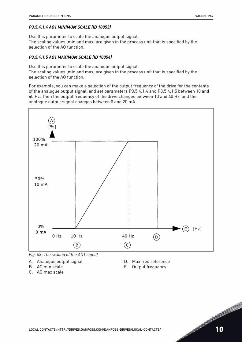
P3.5.4.1.4 AO1 MINIMUM SCALE (ID 10053)
Use this parameter to scale the analogue output signal.The scaling values (min and max) are given in the process unit that is specified by theselection of the AO function.
P3.5.4.1.5 AO1 MAXIMUM SCALE (ID 10054)
Use this parameter to scale the analogue output signal.The scaling values (min and max) are given in the process unit that is specified by theselection of the AO function.
For example, you can make a selection of the output frequency of the drive for the contentsof the analogue output signal, and set parameters P3.5.4.1.4 and P3.5.4.1.5 between 10 and40 Hz. Then the output frequency of the drive changes between 10 and 40 Hz, and theanalogue output signal changes between 0 and 20 mA.
0%
100%
50%
CB
A
D
E0 mA
20 mA
10 mA
[Hz]
[%]
10 Hz 40 Hz0 Hz
Fig. 53: The scaling of the AO1 signalA. Analogue output signalB. AO min scaleC. AO max scale
D. Max freq referenceE. Output frequency
PARAMETER DESCRIPTIONS VACON · 267
LOCAL CONTACTS: HTTP://DRIVES.DANFOSS.COM/DANFOSS-DRIVES/LOCAL-CONTACTS/ 10
10.7 FIELDBUS DATA MAP
P3.6.1 FB DATAOUT 1 SELECTION (ID 852)
Use this parameter to select the data that is sent to the fieldbus with the ID number of theparameter or monitor value.The data is scaled to an unsigned 16-bit format according to the format on the control panel.For example, value 25.5 on the display equals 255.
P3.6.2 FB DATAOUT 2 SELECTION (ID 853)
Use this parameter to select the data that is sent to the fieldbus with the ID number of theparameter or monitor value.The data is scaled to an unsigned 16-bit format according to the format on the control panel.For example, value 25.5 on the display equals 255.
P3.6.3 FB DATAOUT 3 SELECTION (ID 854)
Use this parameter to select the data that is sent to the fieldbus with the ID number of theparameter or monitor value.The data is scaled to an unsigned 16-bit format according to the format on the control panel.For example, value 25.5 on the display equals 255.
P3.6.4 FB DATAOUT 4 SELECTION (ID 855)
Use this parameter to select the data that is sent to the fieldbus with the ID number of theparameter or monitor value.The data is scaled to an unsigned 16-bit format according to the format on the control panel.For example, value 25.5 on the display equals 255.
P3.6.5 FB DATAOUT 5 SELECTION (ID 856)
Use this parameter to select the data that is sent to the fieldbus with the ID number of theparameter or monitor value.The data is scaled to an unsigned 16-bit format according to the format on the control panel.For example, value 25.5 on the display equals 255.
P3.6.6 FB DATAOUT 6 SELECTION (ID 857)
Use this parameter to select the data that is sent to the fieldbus with the ID number of theparameter or monitor value.The data is scaled to an unsigned 16-bit format according to the format on the control panel.For example, value 25.5 on the display equals 255.
P3.6.7 FB DATAOUT 7 SELECTION (ID 858)
Use this parameter to select the data that is sent to the fieldbus with the ID number of theparameter or monitor value.The data is scaled to an unsigned 16-bit format according to the format on the control panel.For example, value 25.5 on the display equals 255.
VACON · 268 PARAMETER DESCRIPTIONS
10 LOCAL CONTACTS: HTTP://DRIVES.DANFOSS.COM/DANFOSS-DRIVES/LOCAL-CONTACTS/
P3.6.8 FB DATAOUT 8 SELECTION (ID 859)
Use this parameter to select the data that is sent to the fieldbus with the ID number of theparameter or monitor value.The data is scaled to an unsigned 16-bit format according to the format on the control panel.For example, value 25.5 on the display equals 255.
10.8 PROHIBIT FREQUENCIES
In some processes it can be necessary to avoid some frequencies because they makeproblems of mechanical resonance. With the Prohibit frequencies function, it is possible toprevent the usage of these frequencies. When the input frequency reference increases, theinternal frequency reference stays at the low limit, until the input frequency reference isabove the high limit.
P3.7.1 PROHIBIT FREQUENCY RANGE 1 LOW LIMIT (ID 509)
Use this parameter to prevent the drive operating on the prohibited frequencies.In some processes it can be necessary to avoid some frequencies because they causemechanical resonance.
P3.7.2 PROHIBIT FREQUENCY RANGE 1 HIGH LIMIT (ID 510)
Use this parameter to prevent the drive operating on the prohibited frequencies.In some processes it can be necessary to avoid some frequencies because they causemechanical resonance.
P3.7.3 PROHIBIT FREQUENCY RANGE 2 LOW LIMIT (ID 511)
Use this parameter to prevent the drive operating on the prohibited frequencies.In some processes it can be necessary to avoid some frequencies because they causemechanical resonance.
P3.7.4 PROHIBIT FREQUENCY RANGE 2 HIGH LIMIT (ID 512)
Use this parameter to prevent the drive operating on the prohibited frequencies.In some processes it can be necessary to avoid some frequencies because they causemechanical resonance.
P3.7.5 PROHIBIT FREQUENCY RANGE 3 LOW LIMIT (ID 513)
Use this parameter to prevent the drive operating on the prohibited frequencies.In some processes it can be necessary to avoid some frequencies because they causemechanical resonance.
P3.7.6 PROHIBIT FREQUENCY RANGE 3 HIGH LIMIT (ID 514)
Use this parameter to prevent the drive operating on the prohibited frequencies.In some processes it can be necessary to avoid some frequencies because they causemechanical resonance.
PARAMETER DESCRIPTIONS VACON · 269
LOCAL CONTACTS: HTTP://DRIVES.DANFOSS.COM/DANFOSS-DRIVES/LOCAL-CONTACTS/ 10
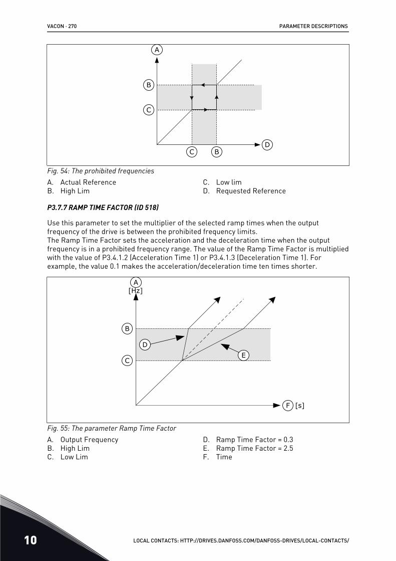
D
A
B
C
C B
Fig. 54: The prohibited frequenciesA. Actual ReferenceB. High Lim
C. Low limD. Requested Reference
P3.7.7 RAMP TIME FACTOR (ID 518)
Use this parameter to set the multiplier of the selected ramp times when the outputfrequency of the drive is between the prohibited frequency limits.The Ramp Time Factor sets the acceleration and the deceleration time when the outputfrequency is in a prohibited frequency range. The value of the Ramp Time Factor is multipliedwith the value of P3.4.1.2 (Acceleration Time 1) or P3.4.1.3 (Deceleration Time 1). Forexample, the value 0.1 makes the acceleration/deceleration time ten times shorter.
A
B
C
DE
F [s]
[Hz]
Fig. 55: The parameter Ramp Time FactorA. Output FrequencyB. High LimC. Low Lim
D. Ramp Time Factor = 0.3E. Ramp Time Factor = 2.5F. Time
VACON · 270 PARAMETER DESCRIPTIONS
10 LOCAL CONTACTS: HTTP://DRIVES.DANFOSS.COM/DANFOSS-DRIVES/LOCAL-CONTACTS/
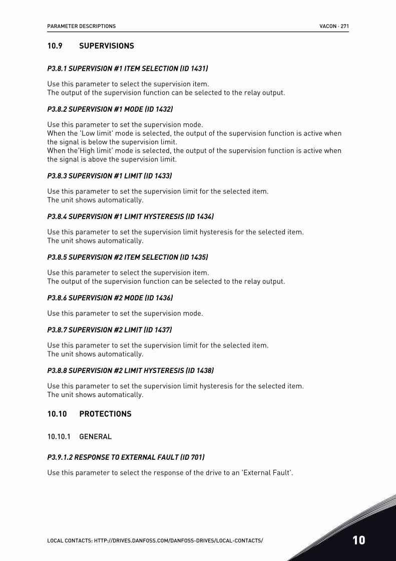
10.9 SUPERVISIONS
P3.8.1 SUPERVISION #1 ITEM SELECTION (ID 1431)
Use this parameter to select the supervision item.The output of the supervision function can be selected to the relay output.
P3.8.2 SUPERVISION #1 MODE (ID 1432)
Use this parameter to set the supervision mode.When the 'Low limit' mode is selected, the output of the supervision function is active whenthe signal is below the supervision limit.When the'High limit' mode is selected, the output of the supervision function is active whenthe signal is above the supervision limit.
P3.8.3 SUPERVISION #1 LIMIT (ID 1433)
Use this parameter to set the supervision limit for the selected item.The unit shows automatically.
P3.8.4 SUPERVISION #1 LIMIT HYSTERESIS (ID 1434)
Use this parameter to set the supervision limit hysteresis for the selected item.The unit shows automatically.
P3.8.5 SUPERVISION #2 ITEM SELECTION (ID 1435)
Use this parameter to select the supervision item.The output of the supervision function can be selected to the relay output.
P3.8.6 SUPERVISION #2 MODE (ID 1436)
Use this parameter to set the supervision mode.
P3.8.7 SUPERVISION #2 LIMIT (ID 1437)
Use this parameter to set the supervision limit for the selected item.The unit shows automatically.
P3.8.8 SUPERVISION #2 LIMIT HYSTERESIS (ID 1438)
Use this parameter to set the supervision limit hysteresis for the selected item.The unit shows automatically.
10.10 PROTECTIONS
10.10.1 GENERAL
P3.9.1.2 RESPONSE TO EXTERNAL FAULT (ID 701)
Use this parameter to select the response of the drive to an 'External Fault'.
PARAMETER DESCRIPTIONS VACON · 271
LOCAL CONTACTS: HTTP://DRIVES.DANFOSS.COM/DANFOSS-DRIVES/LOCAL-CONTACTS/ 10
If a fault occurs, the drive can show a notification of it on the display of the drive.An external fault is activated with a digital input signal. The default digital input is DI3. Youcan also program the response data into a relay output.
P3.9.1.3 INPUT PHASE FAULT (ID 730)
Use this parameter to select the supply phase configuration of the drive.
NOTE!
If you use the 1-phase supply, the value of this parameter must be set to '1-phasesupport'.
P3.9.1.4 UNDERVOLTAGE FAULT (ID 727)
Use this parameter to select if undervoltage faults are saved to the fault history or not.
P3.9.1.5 RESPONSE TO OUTPUT PHASE FAULT (ID 702)
Use this parameter to select the response of the drive to an 'Output Phase' fault.If the measurement of the motor current detects that there is no current in 1 motor phase,an output phase fault occurs.See P3.9.1.2.
P3.9.1.6 RESPONSE TO FIELDBUS COMMUNICATION FAULT (ID 733)
Use this parameter to select the response of the drive to a 'Fieldbus Timeout' fault.If the data connection between the master and the fieldbus board is defective, a fieldbus faultoccurs.
P3.9.1.7 SLOT COMMUNICATION FAULT (ID 734)
Use this parameter to select the response of the drive to a 'Slot Communication' fault.If the drive detects a defective option board, a slot communication fault occurs.See P3.9.1.2.
P3.9.1.8 THERMISTOR FAULT (ID 732)
Use this parameter to select the response of the drive to a 'Thermistor' fault.If the thermistor detects too high temperature, a thermistor fault occurs.See P3.9.1.2.
P3.9.1.9 PID SOFT FILL FAULT (ID 748)
Use this parameter to select the response of the drive to a 'PID Soft Fill' fault.If the PIDFeedback value does not reach the set level within the time limit, a soft fill faultoccurs.See P3.9.1.2.
P3.9.1.10 RESPONSE TO PID SUPERVISION FAULT (ID 749)
Use this parameter to select the response of the drive to a 'PID Supervision' fault.
VACON · 272 PARAMETER DESCRIPTIONS
10 LOCAL CONTACTS: HTTP://DRIVES.DANFOSS.COM/DANFOSS-DRIVES/LOCAL-CONTACTS/
If the PID feedback value is not within the supervision limits for longer than the supervisiondelay, a PID supervision fault occurs.See P3.9.1.2.
P3.9.1.11 RESPONSE TO EXTERNAL PID SUPERVISION FAULT (ID 757)
Use this parameter to select the response of the drive to a 'PID Supervision' fault.If the PID feedback value is not within the supervision limits for longer than the supervisiondelay, a PID supervision fault occurs.See P3.9.1.2.
P3.9.1.12 EARTH FAULT (ID 703)
Use this parameter to select the response of the drive to an 'Earth Fault'.If the measurement of the current detects that the sum of the motor phase currents is not 0,an earth fault occurs.See P3.9.1.2.
NOTE!
You can configure this fault only in enclosure sizes MR7, MR8, and MR9.
P3.9.1.13 PRESET ALARM FREQUENCY (ID 183)
Use this parameter to set the frequency of the drive when a fault is active and the responseto the fault is set to 'Alarm + Preset Frequency'.
P3.9.1.14 RESPONSE TO SAFE TORQUE OFF (STO) FAULT (ID 775)
Use this parameter to select the response of the drive to a 'STO Fault'.
This parameter defines drive operation when Safe Torque Off (STO) function is activated (e.g.emergency stop button has been pressed or some other STO operation has been activated).See P3.9.1.2.
P3.9.1.15 STARTUP PREVENTED FAULT (ID 15593)
Use this parameter to select the response of the AC drive to a "Startup prevented" fault.
10.10.2 MOTOR THERMAL PROTECTIONSThe motor thermal protection prevents the motor from becoming too hot.
The AC drive can supply a current that is higher than the nominal current. The high currentcan be necessary to the load, and it must be used. In these conditions, there is a risk of athermal overload. Low frequencies have a higher risk. At low frequencies, the cooling effectand the capacity of the motor decrease. If the motor has an external fan, the load reductionat low frequencies is small.
The motor thermal protection is based on calculations. The protection function uses theoutput current of the drive to know what is the load on the motor. If the control board is notenergised, the calculations are reset.
PARAMETER DESCRIPTIONS VACON · 273
LOCAL CONTACTS: HTTP://DRIVES.DANFOSS.COM/DANFOSS-DRIVES/LOCAL-CONTACTS/ 10
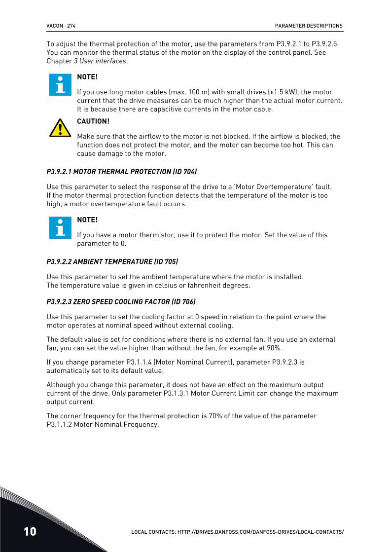
To adjust the thermal protection of the motor, use the parameters from P3.9.2.1 to P3.9.2.5.You can monitor the thermal status of the motor on the display of the control panel. SeeChapter 3 User interfaces.
NOTE!
If you use long motor cables (max. 100 m) with small drives (≤1.5 kW), the motorcurrent that the drive measures can be much higher than the actual motor current.It is because there are capacitive currents in the motor cable.CAUTION!
Make sure that the airflow to the motor is not blocked. If the airflow is blocked, thefunction does not protect the motor, and the motor can become too hot. This cancause damage to the motor.
P3.9.2.1 MOTOR THERMAL PROTECTION (ID 704)
Use this parameter to select the response of the drive to a 'Motor Overtemperature' fault.If the motor thermal protection function detects that the temperature of the motor is toohigh, a motor overtemperature fault occurs.
NOTE!
If you have a motor thermistor, use it to protect the motor. Set the value of thisparameter to 0.
P3.9.2.2 AMBIENT TEMPERATURE (ID 705)
Use this parameter to set the ambient temperature where the motor is installed.The temperature value is given in celsius or fahrenheit degrees.
P3.9.2.3 ZERO SPEED COOLING FACTOR (ID 706)
Use this parameter to set the cooling factor at 0 speed in relation to the point where themotor operates at nominal speed without external cooling.
The default value is set for conditions where there is no external fan. If you use an externalfan, you can set the value higher than without the fan, for example at 90%.
If you change parameter P3.1.1.4 (Motor Nominal Current), parameter P3.9.2.3 isautomatically set to its default value.
Although you change this parameter, it does not have an effect on the maximum outputcurrent of the drive. Only parameter P3.1.3.1 Motor Current Limit can change the maximumoutput current.
The corner frequency for the thermal protection is 70% of the value of the parameterP3.1.1.2 Motor Nominal Frequency.
VACON · 274 PARAMETER DESCRIPTIONS
10 LOCAL CONTACTS: HTTP://DRIVES.DANFOSS.COM/DANFOSS-DRIVES/LOCAL-CONTACTS/
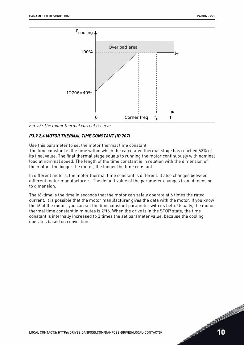
ffn
ID706=40%
0
IT100%
Overload area
Pcooling
Corner freq
Fig. 56: The motor thermal current IT curve
P3.9.2.4 MOTOR THERMAL TIME CONSTANT (ID 707)
Use this parameter to set the motor thermal time constant.The time constant is the time within which the calculated thermal stage has reached 63% ofits final value. The final thermal stage equals to running the motor continuously with nominalload at nominal speed. The length of the time constant is in relation with the dimension ofthe motor. The bigger the motor, the longer the time constant.
In different motors, the motor thermal time constant is different. It also changes betweendifferent motor manufacturers. The default value of the parameter changes from dimensionto dimension.
The t6-time is the time in seconds that the motor can safely operate at 6 times the ratedcurrent. It is possible that the motor manufacturer gives the data with the motor. If you knowthe t6 of the motor, you can set the time constant parameter with its help. Usually, the motorthermal time constant in minutes is 2*t6. When the drive is in the STOP state, the timeconstant is internally increased to 3 times the set parameter value, because the coolingoperates based on convection.
PARAMETER DESCRIPTIONS VACON · 275
LOCAL CONTACTS: HTTP://DRIVES.DANFOSS.COM/DANFOSS-DRIVES/LOCAL-CONTACTS/ 10
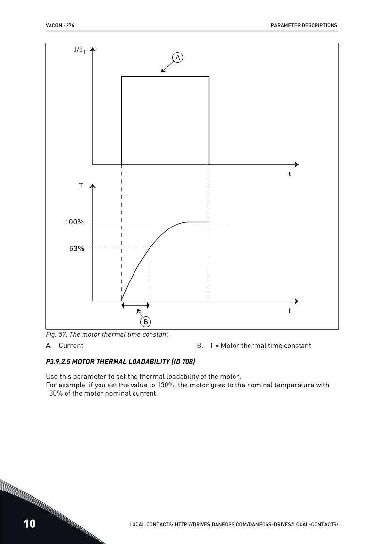
I/IT
100%
63%
T
t
t
A
B
Fig. 57: The motor thermal time constantA. Current B. T = Motor thermal time constant
P3.9.2.5 MOTOR THERMAL LOADABILITY (ID 708)
Use this parameter to set the thermal loadability of the motor.For example, if you set the value to 130%, the motor goes to the nominal temperature with130% of the motor nominal current.
VACON · 276 PARAMETER DESCRIPTIONS
10 LOCAL CONTACTS: HTTP://DRIVES.DANFOSS.COM/DANFOSS-DRIVES/LOCAL-CONTACTS/
t
t
I/I
T
105%
A
C
B
D80%100%130%
Fig. 58: The calculation of the motor temperatureA. CurrentB. Fault/Alarm
C. Trip areaD. Loadability
10.10.3 MOTOR STALL PROTECTIONThe motor stall protection function gives protection to the motor against short overloads. Anoverload can be caused, for example, by a stalled shaft. It is possible to set the reaction timeof the stall protection shorter than that of the motor thermal protection.
The stall status of the motor is specified with parameters P3.9.3.2 Stall Current and P3.9.3.4Stall Frequency Limit. If the current is higher than the limit, and the output frequency islower than the limit, the motor is in a stall status.
The stall protection is a type of overcurrent protection.
NOTE!
If you use long motor cables (max. 100 m) with small drives (≤1.5 kW), the motorcurrent that the drive measures can be much higher than the actual motor current.It is because there are capacitive currents in the motor cable.
PARAMETER DESCRIPTIONS VACON · 277
LOCAL CONTACTS: HTTP://DRIVES.DANFOSS.COM/DANFOSS-DRIVES/LOCAL-CONTACTS/ 10
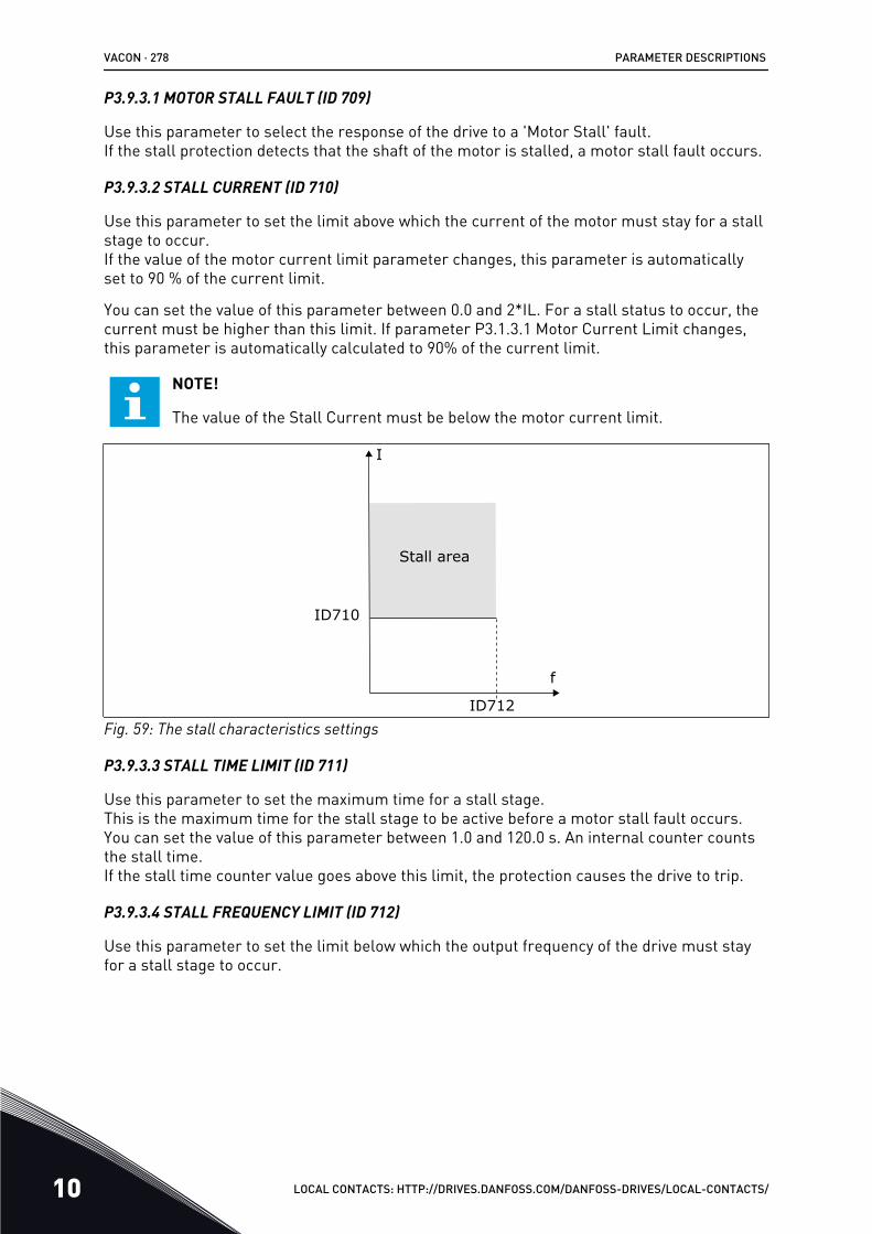
P3.9.3.1 MOTOR STALL FAULT (ID 709)
Use this parameter to select the response of the drive to a 'Motor Stall' fault.If the stall protection detects that the shaft of the motor is stalled, a motor stall fault occurs.
P3.9.3.2 STALL CURRENT (ID 710)
Use this parameter to set the limit above which the current of the motor must stay for a stallstage to occur.If the value of the motor current limit parameter changes, this parameter is automaticallyset to 90 % of the current limit.
You can set the value of this parameter between 0.0 and 2*IL. For a stall status to occur, thecurrent must be higher than this limit. If parameter P3.1.3.1 Motor Current Limit changes,this parameter is automatically calculated to 90% of the current limit.
NOTE!
The value of the Stall Current must be below the motor current limit.
f
I
ID710
ID712
Stall area
Fig. 59: The stall characteristics settings
P3.9.3.3 STALL TIME LIMIT (ID 711)
Use this parameter to set the maximum time for a stall stage.This is the maximum time for the stall stage to be active before a motor stall fault occurs.You can set the value of this parameter between 1.0 and 120.0 s. An internal counter countsthe stall time.If the stall time counter value goes above this limit, the protection causes the drive to trip.
P3.9.3.4 STALL FREQUENCY LIMIT (ID 712)
Use this parameter to set the limit below which the output frequency of the drive must stayfor a stall stage to occur.
VACON · 278 PARAMETER DESCRIPTIONS
10 LOCAL CONTACTS: HTTP://DRIVES.DANFOSS.COM/DANFOSS-DRIVES/LOCAL-CONTACTS/
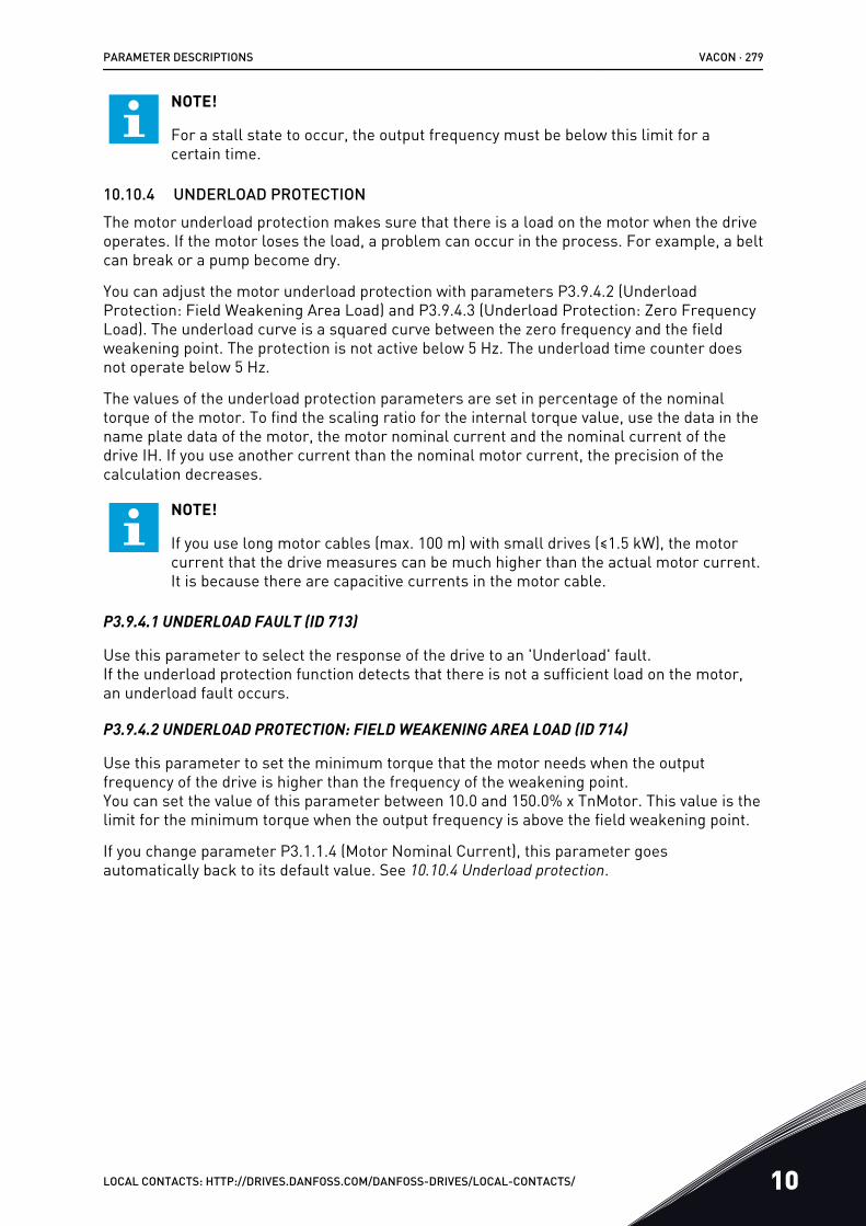
NOTE!
For a stall state to occur, the output frequency must be below this limit for acertain time.
10.10.4 UNDERLOAD PROTECTIONThe motor underload protection makes sure that there is a load on the motor when the driveoperates. If the motor loses the load, a problem can occur in the process. For example, a beltcan break or a pump become dry.
You can adjust the motor underload protection with parameters P3.9.4.2 (UnderloadProtection: Field Weakening Area Load) and P3.9.4.3 (Underload Protection: Zero FrequencyLoad). The underload curve is a squared curve between the zero frequency and the fieldweakening point. The protection is not active below 5 Hz. The underload time counter doesnot operate below 5 Hz.
The values of the underload protection parameters are set in percentage of the nominaltorque of the motor. To find the scaling ratio for the internal torque value, use the data in thename plate data of the motor, the motor nominal current and the nominal current of thedrive IH. If you use another current than the nominal motor current, the precision of thecalculation decreases.
NOTE!
If you use long motor cables (max. 100 m) with small drives (≤1.5 kW), the motorcurrent that the drive measures can be much higher than the actual motor current.It is because there are capacitive currents in the motor cable.
P3.9.4.1 UNDERLOAD FAULT (ID 713)
Use this parameter to select the response of the drive to an 'Underload' fault.If the underload protection function detects that there is not a sufficient load on the motor,an underload fault occurs.
P3.9.4.2 UNDERLOAD PROTECTION: FIELD WEAKENING AREA LOAD (ID 714)
Use this parameter to set the minimum torque that the motor needs when the outputfrequency of the drive is higher than the frequency of the weakening point.You can set the value of this parameter between 10.0 and 150.0% x TnMotor. This value is thelimit for the minimum torque when the output frequency is above the field weakening point.
If you change parameter P3.1.1.4 (Motor Nominal Current), this parameter goesautomatically back to its default value. See 10.10.4 Underload protection.
PARAMETER DESCRIPTIONS VACON · 279
LOCAL CONTACTS: HTTP://DRIVES.DANFOSS.COM/DANFOSS-DRIVES/LOCAL-CONTACTS/ 10
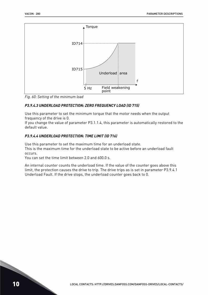
ID714
ID715
f
5 Hz
Underload area
Torque
Field weakeningpoint
Fig. 60: Setting of the minimum load
P3.9.4.3 UNDERLOAD PROTECTION: ZERO FREQUENCY LOAD (ID 715)
Use this parameter to set the minimum torque that the motor needs when the outputfrequency of the drive is 0.If you change the value of parameter P3.1.1.4, this parameter is automatically restored to thedefault value.
P3.9.4.4 UNDERLOAD PROTECTION: TIME LIMIT (ID 716)
Use this parameter to set the maximum time for an underload state.This is the maximum time for the underload state to be active before an underload faultoccurs.You can set the time limit between 2.0 and 600.0 s.
An internal counter counts the underload time. If the value of the counter goes above thislimit, the protection causes the drive to trip. The drive trips as is set in parameter P3.9.4.1Underload Fault. If the drive stops, the underload counter goes back to 0.
VACON · 280 PARAMETER DESCRIPTIONS
10 LOCAL CONTACTS: HTTP://DRIVES.DANFOSS.COM/DANFOSS-DRIVES/LOCAL-CONTACTS/
ID716
A
B
C
DE
F
Fig. 61: The Underload time counter functionA. Underload time counterB. Trip areaC. Trip/warning ID713
D. TimeE. UnderloadF. No underload
10.10.5 QUICK STOP
P3.9.5.1 QUICK STOP MODE (ID 1276)
Use this parameter to select how the drive stops when the quick stop command is given fromDI or Fieldbus.
P3.9.5.2 QUICK STOP ACTIVATION (ID 1213)
Use this parameter to select the digital input signal that activates a Quick Stop function.The Quick Stop function stops the drive regardless of the control place or the state of thecontrol signals.
P3.9.5.3 QUICK STOP DECELERATION TIME (ID 1256)
Use this parameter to set the time that is necessary for the output frequency to decreasefrom maximum frequency to 0 when a quick stop command is given.The value of this parameter is applied only when the quick stop mode parameter is set to'Quick Stop Deceleration time'.
P3.9.5.4 RESPONSE TO QUICK STOP FAULT (ID 744)
Use this parameter to select the response of the drive to a 'Quick Stop' fault.If the quick stop command is given from DI or Fieldbus, a quick stop fault occurs.
With the quick stop function, you can stop the drive in an unusual procedure from I/O orFieldbus in unusual conditions. When the quick stop function is active, you can make thedrive decelerate and stop. It is possible to program an alarm or fault to put a mark in thefault history that there was a request for a quick stop.
PARAMETER DESCRIPTIONS VACON · 281
LOCAL CONTACTS: HTTP://DRIVES.DANFOSS.COM/DANFOSS-DRIVES/LOCAL-CONTACTS/ 10
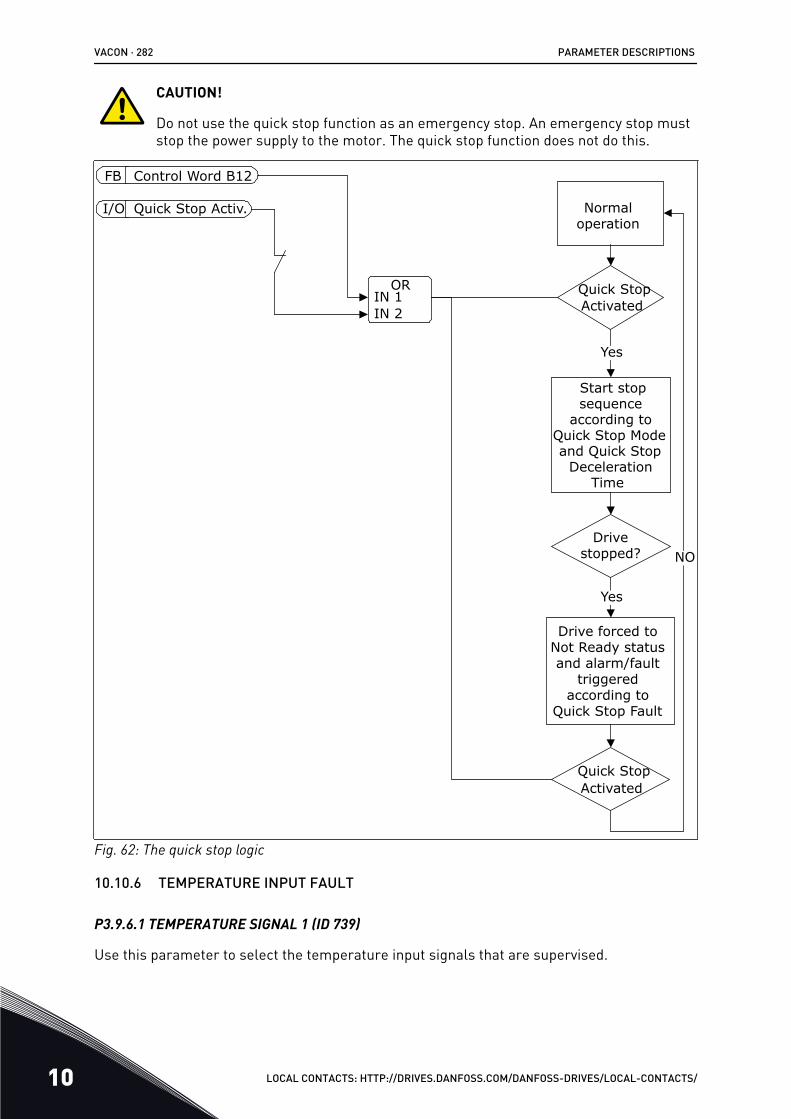
CAUTION!
Do not use the quick stop function as an emergency stop. An emergency stop muststop the power supply to the motor. The quick stop function does not do this.
ORIN 1IN 2
FB
I/O
Yes
Control Word B12
Quick Stop Activ. Normal operation
Start stopsequence
according toQuick Stop Modeand Quick Stop
DecelerationTime
Quick StopActivated
Quick StopActivated
NODrive
stopped?
Yes
Drive forced to Not Ready status and alarm/fault
triggered according to
Quick Stop Fault
Fig. 62: The quick stop logic
10.10.6 TEMPERATURE INPUT FAULT
P3.9.6.1 TEMPERATURE SIGNAL 1 (ID 739)
Use this parameter to select the temperature input signals that are supervised.
VACON · 282 PARAMETER DESCRIPTIONS
10 LOCAL CONTACTS: HTTP://DRIVES.DANFOSS.COM/DANFOSS-DRIVES/LOCAL-CONTACTS/
The maximum value is taken from the set signals and used for alarm and fault triggering.
NOTE!
Only the 6 first temperature inputs are supported (the boards from slot A to slot E).
P3.9.6.2 ALARM LIMIT 1 (ID 741)
Use this parameter to set the temperature alarm limit.
Only the inputs that are set with parameter P3.9.6.1 are compared.
P3.9.6.3 FAULT LIMIT 1 (ID 742)
Use this parameter to set the temperature fault limit.
Only the inputs that are set with parameter P3.9.6.1 are compared.
P3.9.6.4 FAULT LIMIT RESPONSE 1 (ID 740)
Use this parameter to select the response of the drive to 'Temperature' fault.
P3.9.6.5 TEMPERATURE SIGNAL 2 (ID 763)
Use this parameter to select the temperature input signals that are supervised.
The maximum value is taken from the set signals and used for alarm and fault triggering.
NOTE!
Only the 6 first temperature inputs are supported (the boards from slot A to slot E).
P3.9.6.6 ALARM LIMIT 2 (ID 764)
Use this parameter to set the temperature alarm limit.
Only the inputs that are set with parameter P3.9.6.5 are compared.
P3.9.6.7 FAULT LIMIT 2 (ID 765)
Use this parameter to set the temperature fault limit.
Only the inputs that are set with parameter P3.9.6.5 are compared.
P3.9.6.8 FAULT LIMIT RESPONSE 2 (ID 766)
Use this parameter to select the response of the drive to 'Temperature' fault.
NOTE!
Temperature input settings are only available if a B8 or BH option board isinstalled.
PARAMETER DESCRIPTIONS VACON · 283
LOCAL CONTACTS: HTTP://DRIVES.DANFOSS.COM/DANFOSS-DRIVES/LOCAL-CONTACTS/ 10
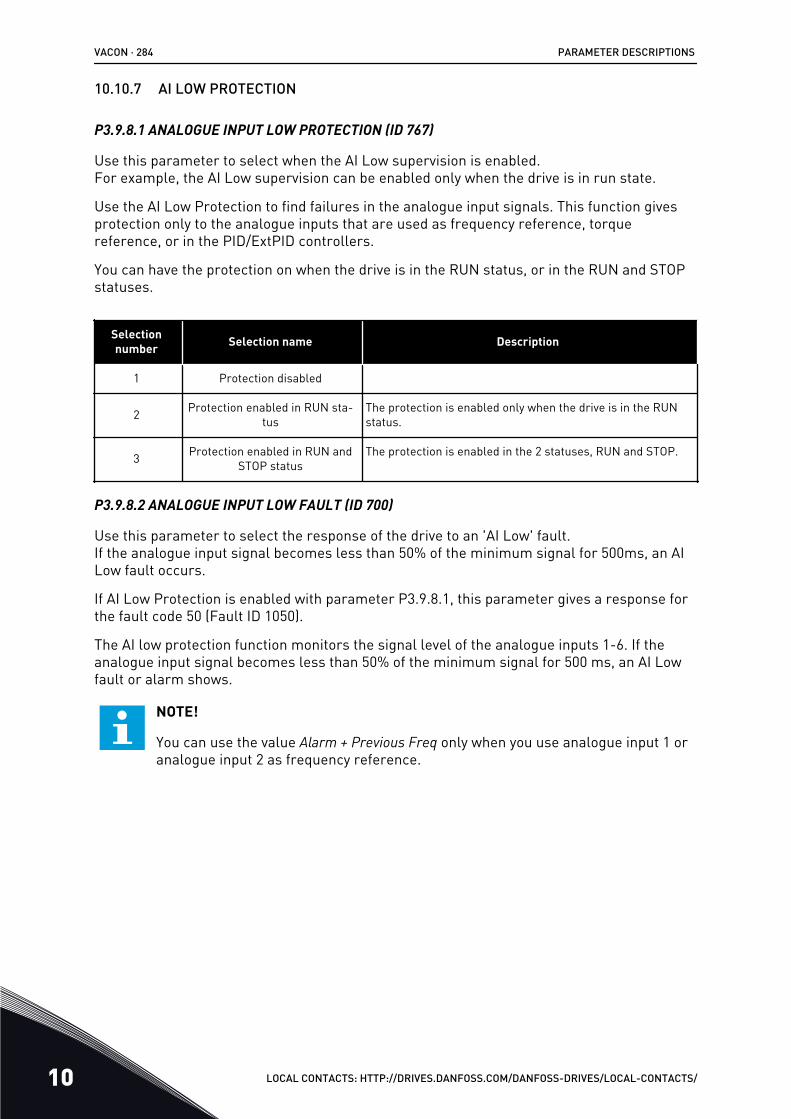
10.10.7 AI LOW PROTECTION
P3.9.8.1 ANALOGUE INPUT LOW PROTECTION (ID 767)
Use this parameter to select when the AI Low supervision is enabled.For example, the AI Low supervision can be enabled only when the drive is in run state.
Use the AI Low Protection to find failures in the analogue input signals. This function givesprotection only to the analogue inputs that are used as frequency reference, torquereference, or in the PID/ExtPID controllers.
You can have the protection on when the drive is in the RUN status, or in the RUN and STOPstatuses.
Selectionnumber Selection name Description
1 Protection disabled
2 Protection enabled in RUN sta-tus
The protection is enabled only when the drive is in the RUNstatus.
3 Protection enabled in RUN andSTOP status
The protection is enabled in the 2 statuses, RUN and STOP.
P3.9.8.2 ANALOGUE INPUT LOW FAULT (ID 700)
Use this parameter to select the response of the drive to an 'AI Low' fault.If the analogue input signal becomes less than 50% of the minimum signal for 500ms, an AILow fault occurs.
If AI Low Protection is enabled with parameter P3.9.8.1, this parameter gives a response forthe fault code 50 (Fault ID 1050).
The AI low protection function monitors the signal level of the analogue inputs 1-6. If theanalogue input signal becomes less than 50% of the minimum signal for 500 ms, an AI Lowfault or alarm shows.
NOTE!
You can use the value Alarm + Previous Freq only when you use analogue input 1 oranalogue input 2 as frequency reference.
VACON · 284 PARAMETER DESCRIPTIONS
10 LOCAL CONTACTS: HTTP://DRIVES.DANFOSS.COM/DANFOSS-DRIVES/LOCAL-CONTACTS/
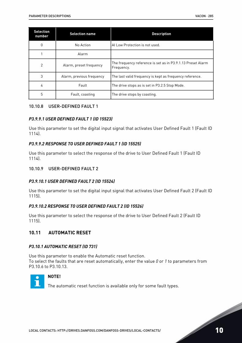
Selectionnumber Selection name Description
0 No Action AI Low Protection is not used.
1 Alarm
2 Alarm, preset frequency The frequency reference is set as in P3.9.1.13 Preset AlarmFrequency.
3 Alarm, previous frequency The last valid frequency is kept as frequency reference.
4 Fault The drive stops as is set in P3.2.5 Stop Mode.
5 Fault, coasting The drive stops by coasting.
10.10.8 USER-DEFINED FAULT 1
P3.9.9.1 USER DEFINED FAULT 1 (ID 15523)
Use this parameter to set the digital input signal that activates User Defined Fault 1 (Fault ID1114).
P3.9.9.2 RESPONSE TO USER DEFINED FAULT 1 (ID 15525)
Use this parameter to select the response of the drive to User Defined Fault 1 (Fault ID1114).
10.10.9 USER-DEFINED FAULT 2
P3.9.10.1 USER DEFINED FAULT 2 (ID 15524)
Use this parameter to set the digital input signal that activates User Defined Fault 2 (Fault ID1115).
P3.9.10.2 RESPONSE TO USER DEFINED FAULT 2 (ID 15526)
Use this parameter to select the response of the drive to User Defined Fault 2 (Fault ID1115).
10.11 AUTOMATIC RESET
P3.10.1 AUTOMATIC RESET (ID 731)
Use this parameter to enable the Automatic reset function.To select the faults that are reset automatically, enter the value 0 or 1 to parameters fromP3.10.6 to P3.10.13.
NOTE!
The automatic reset function is available only for some fault types.
PARAMETER DESCRIPTIONS VACON · 285
LOCAL CONTACTS: HTTP://DRIVES.DANFOSS.COM/DANFOSS-DRIVES/LOCAL-CONTACTS/ 10
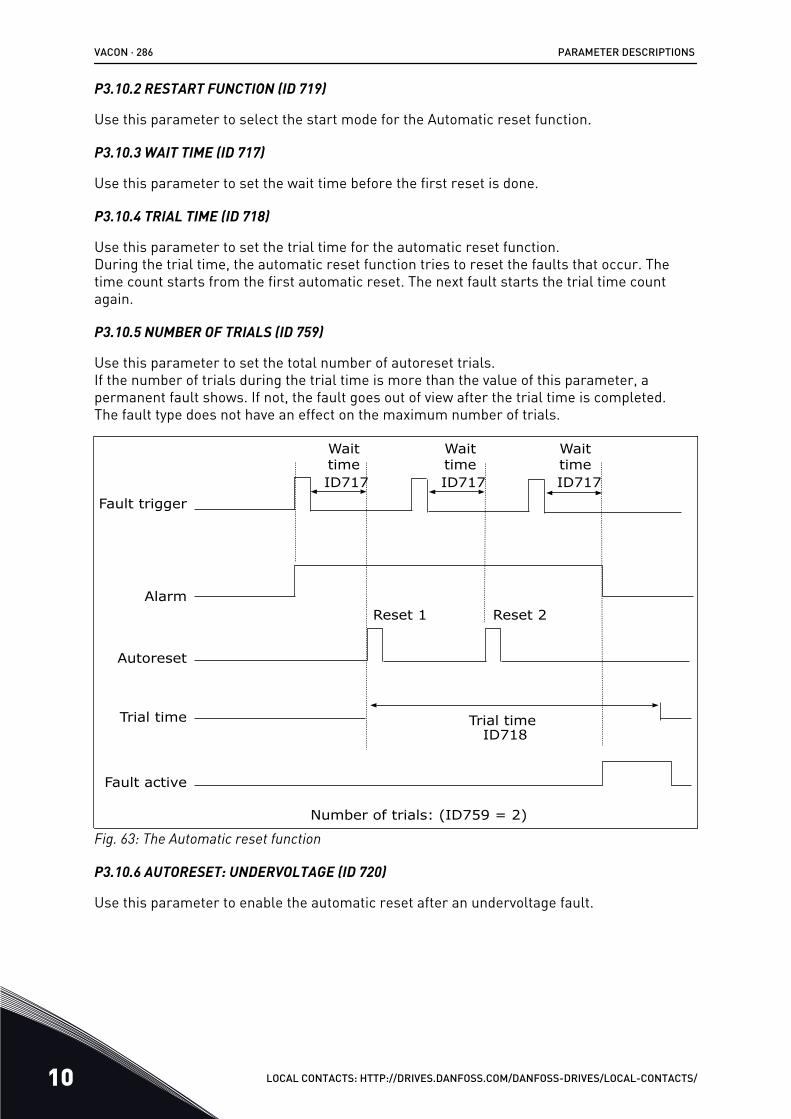
P3.10.2 RESTART FUNCTION (ID 719)
Use this parameter to select the start mode for the Automatic reset function.
P3.10.3 WAIT TIME (ID 717)
Use this parameter to set the wait time before the first reset is done.
P3.10.4 TRIAL TIME (ID 718)
Use this parameter to set the trial time for the automatic reset function.During the trial time, the automatic reset function tries to reset the faults that occur. Thetime count starts from the first automatic reset. The next fault starts the trial time countagain.
P3.10.5 NUMBER OF TRIALS (ID 759)
Use this parameter to set the total number of autoreset trials.If the number of trials during the trial time is more than the value of this parameter, apermanent fault shows. If not, the fault goes out of view after the trial time is completed.The fault type does not have an effect on the maximum number of trials.
Fault trigger
Autoreset
Trial time
Wait time
Wait time
Wait time
ID717
Reset 1 Reset 2
Trial timeID718
Fault active
Alarm
Number of trials: (ID759 = 2)
ID717 ID717
Fig. 63: The Automatic reset function
P3.10.6 AUTORESET: UNDERVOLTAGE (ID 720)
Use this parameter to enable the automatic reset after an undervoltage fault.
VACON · 286 PARAMETER DESCRIPTIONS
10 LOCAL CONTACTS: HTTP://DRIVES.DANFOSS.COM/DANFOSS-DRIVES/LOCAL-CONTACTS/
P3.10.7 AUTORESET: OVERVOLTAGE (ID 721)
Use this parameter to enable the automatic reset after an overvoltage fault.
P3.10.8 AUTORESET: OVERCURRENT (ID 722)
Use this parameter to enable the automatic reset after an overcurrent fault.
P3.10.9 AUTORESET: AI LOW (ID 723)
Use this parameter to enable the automatic reset after a fault caused by low AI signal.
P3.10.10 AUTORESET: UNIT OVERTEMPERATURE (ID 724)
Use this parameter to enable the automatic reset after a fault caused by unitovertemperature.
P3.10.11 AUTORESET: MOTOR OVERTEMPERATURE (ID 725)
Use this parameter to enable the automatic reset after a fault caused by motorovertemperature.
P3.10.12 AUTORESET: EXTERNAL FAULT (ID 726)
Use this parameter to enable the automatic reset after an external fault.
P3.10.13 AUTORESET: UNDERLOAD FAULT (ID 738)
Use this parameter to enable the automatic reset after an underload fault.
P3.10.14 AUTORESET: PID SUPERVISION FAULT (ID 776)
Use this parameter to enable the automatic reset after a PID supervision fault.
P3.10.15 AUTORESET: EXT PID SUPERVISION FAULT (ID 777)
Use this parameter to enable the automatic reset after an external PID supervision fault.
10.12 APPLICATION SETTINGS
P3.11.1 PASSWORD (ID 1806)
Use this parameter to set the administrator password.
P3.11.2 C/F SELECTION (ID 1197)
Use this parameter to set the temperature measuring unit.The system shows all the temperature-related parameters and monitoring values in the setunit.
P3.11.3 KW/HP SELECTION (ID 1198)
Use this parameter to set the power measuring unit.
PARAMETER DESCRIPTIONS VACON · 287
LOCAL CONTACTS: HTTP://DRIVES.DANFOSS.COM/DANFOSS-DRIVES/LOCAL-CONTACTS/ 10
The system shows all the power-related parameters and monitoring values in the set unit.
3.11.4 MULTIMONITOR VIEW (ID 1196)
Use this parameter to set the division of the display of the control panel into sections in themultimonitor view.
3.11.5 FUNCT BUTTON CONFIGURATION (ID 1195)
Use this parameter to set the values of the FUNCT button.The values that you set with this parameter will be available when you push the FUNCTbutton on the keypad.
10.13 TIMER FUNCTIONS
The timer functions make it possible for the internal RTC (Real Time Clock) to controlfunctions. All the functions that can be controlled with a digital input, can also be controlledwith the RTC, with time channels 1-3. It is not necessary to have an external PLC to control adigital input. You can program the closed and opened intervals of the input internally.
To get the best results of the timer functions, install a battery, and make the settings of theReal Time Clock carefully in the Start-up wizard. The battery is available as an option.
NOTE!
We do not recommend that you use the timer functions without an auxiliary battery.The time and date settings of the drive are reset at each power down, if there is nobattery for the RTC.
TIME CHANNELS
You can assign the output of the interval and/or timer functions to time channels 1-3. You canuse the time channels to control on/off type functions, for example relay outputs or digitalinputs. To configure the on/off logic of the time channels, assign intervals and/or timers tothem. A time channel can be controlled by many different intervals or timers.
VACON · 288 PARAMETER DESCRIPTIONS
10 LOCAL CONTACTS: HTTP://DRIVES.DANFOSS.COM/DANFOSS-DRIVES/LOCAL-CONTACTS/
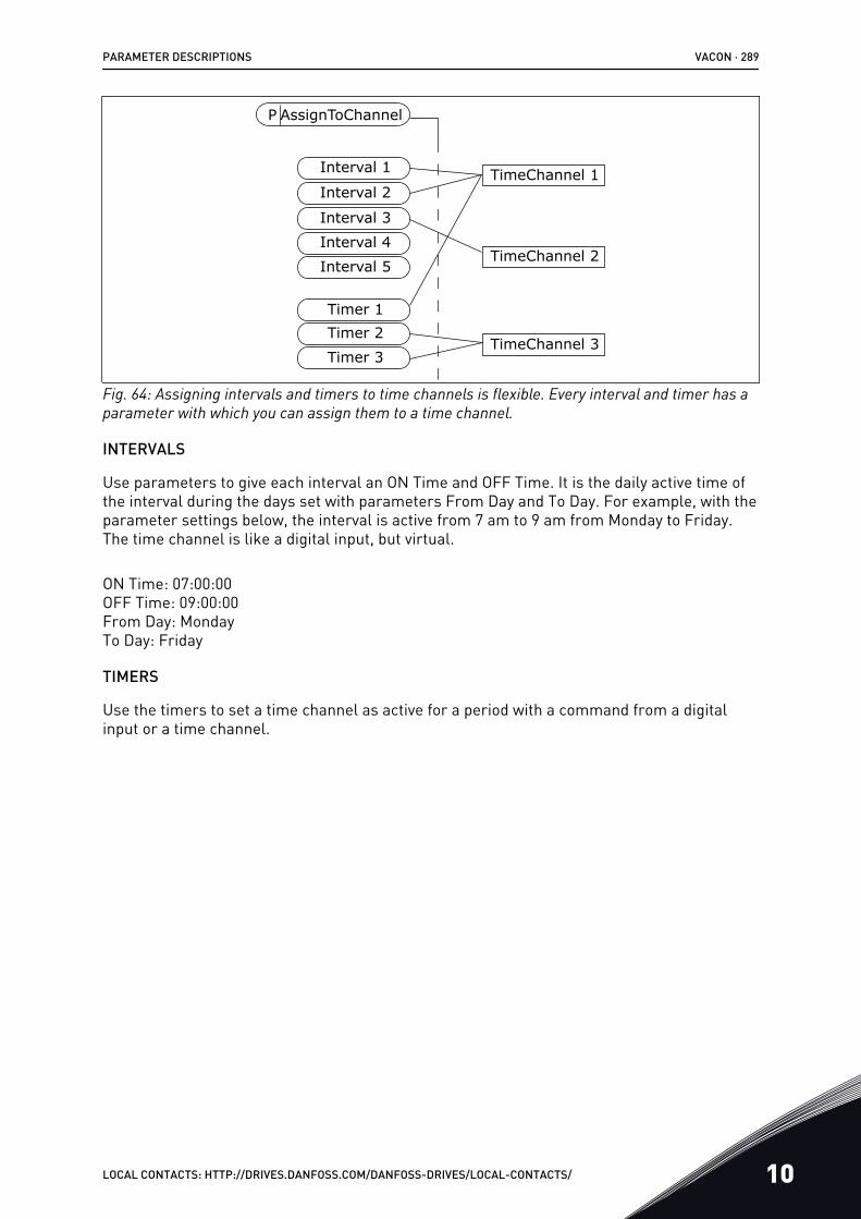
P AssignToChannel
Interval 1
Interval 2
Interval 3Interval 4
Timer 1Timer 2Timer 3
Interval 5
TimeChannel 1
TimeChannel 2
TimeChannel 3
Fig. 64: Assigning intervals and timers to time channels is flexible. Every interval and timer has aparameter with which you can assign them to a time channel.
INTERVALS
Use parameters to give each interval an ON Time and OFF Time. It is the daily active time ofthe interval during the days set with parameters From Day and To Day. For example, with theparameter settings below, the interval is active from 7 am to 9 am from Monday to Friday.The time channel is like a digital input, but virtual.
ON Time: 07:00:00OFF Time: 09:00:00From Day: MondayTo Day: Friday
TIMERS
Use the timers to set a time channel as active for a period with a command from a digitalinput or a time channel.
PARAMETER DESCRIPTIONS VACON · 289
LOCAL CONTACTS: HTTP://DRIVES.DANFOSS.COM/DANFOSS-DRIVES/LOCAL-CONTACTS/ 10
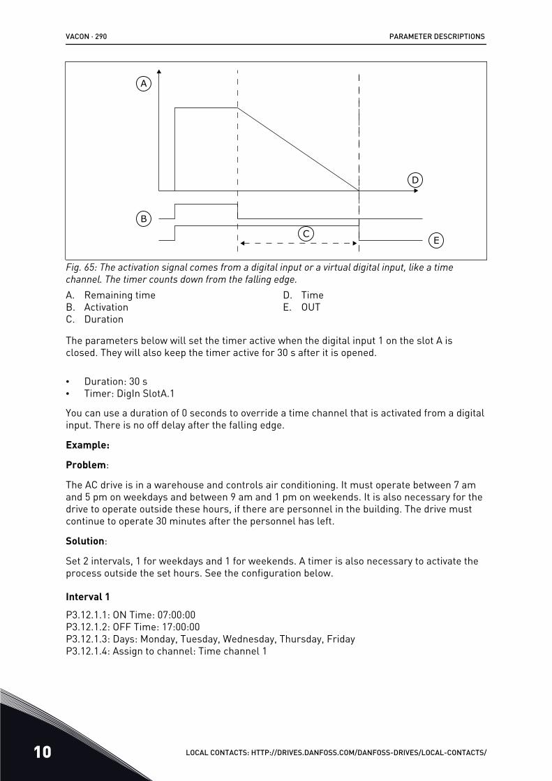
A
B
D
CE
Fig. 65: The activation signal comes from a digital input or a virtual digital input, like a timechannel. The timer counts down from the falling edge.A. Remaining timeB. ActivationC. Duration
D. TimeE. OUT
The parameters below will set the timer active when the digital input 1 on the slot A isclosed. They will also keep the timer active for 30 s after it is opened.
• Duration: 30 s• Timer: DigIn SlotA.1
You can use a duration of 0 seconds to override a time channel that is activated from a digitalinput. There is no off delay after the falling edge.
Example:
Problem:
The AC drive is in a warehouse and controls air conditioning. It must operate between 7 amand 5 pm on weekdays and between 9 am and 1 pm on weekends. It is also necessary for thedrive to operate outside these hours, if there are personnel in the building. The drive mustcontinue to operate 30 minutes after the personnel has left.
Solution:
Set 2 intervals, 1 for weekdays and 1 for weekends. A timer is also necessary to activate theprocess outside the set hours. See the configuration below.
Interval 1P3.12.1.1: ON Time: 07:00:00P3.12.1.2: OFF Time: 17:00:00P3.12.1.3: Days: Monday, Tuesday, Wednesday, Thursday, FridayP3.12.1.4: Assign to channel: Time channel 1
VACON · 290 PARAMETER DESCRIPTIONS
10 LOCAL CONTACTS: HTTP://DRIVES.DANFOSS.COM/DANFOSS-DRIVES/LOCAL-CONTACTS/
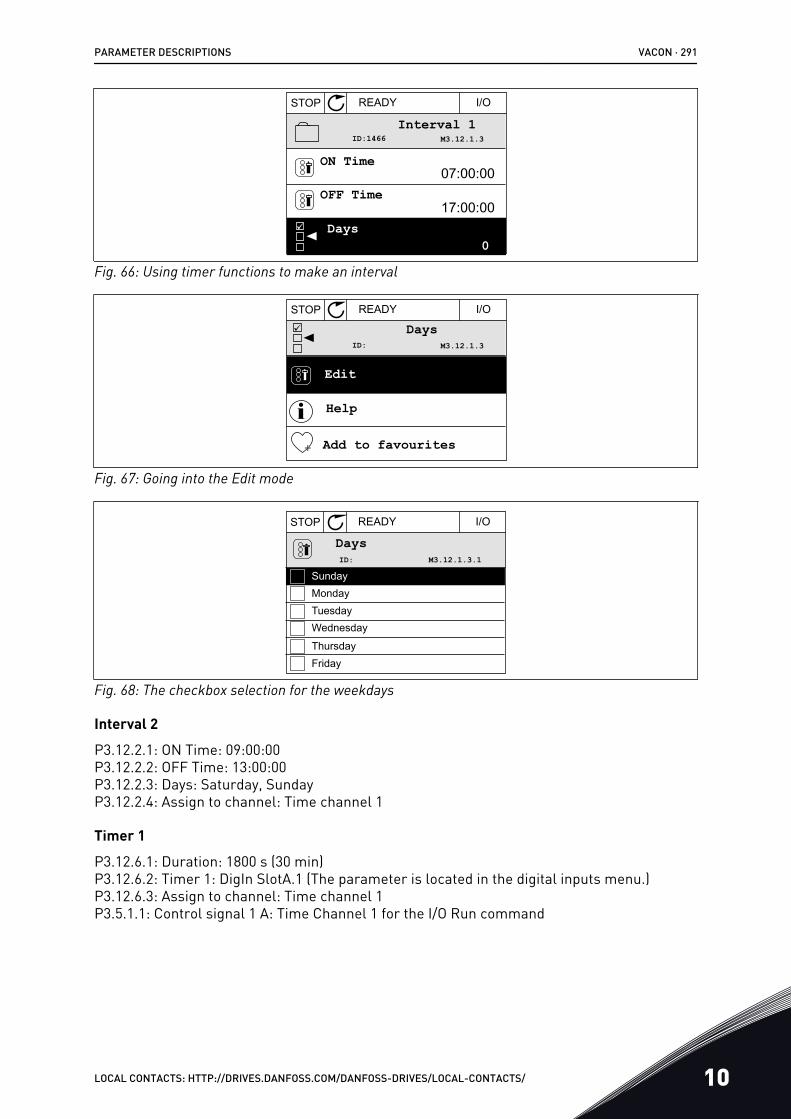
17:00:00
07:00:00
M3.12.1.3ID:1466
STOP READY I/O
Interval 1
Days
OFF Time
ON Time
0Fig. 66: Using timer functions to make an interval
M3.12.1.3ID:
STOP READY I/O
Edit
Help
Add to favourites
Days
Fig. 67: Going into the Edit mode
STOP READY I/O
DaysM3.12.1.3.1ID:
MondayTuesdayWednesday
ThursdayFriday
Sunday
Fig. 68: The checkbox selection for the weekdays
Interval 2P3.12.2.1: ON Time: 09:00:00P3.12.2.2: OFF Time: 13:00:00P3.12.2.3: Days: Saturday, SundayP3.12.2.4: Assign to channel: Time channel 1
Timer 1P3.12.6.1: Duration: 1800 s (30 min)P3.12.6.2: Timer 1: DigIn SlotA.1 (The parameter is located in the digital inputs menu.)P3.12.6.3: Assign to channel: Time channel 1P3.5.1.1: Control signal 1 A: Time Channel 1 for the I/O Run command
PARAMETER DESCRIPTIONS VACON · 291
LOCAL CONTACTS: HTTP://DRIVES.DANFOSS.COM/DANFOSS-DRIVES/LOCAL-CONTACTS/ 10
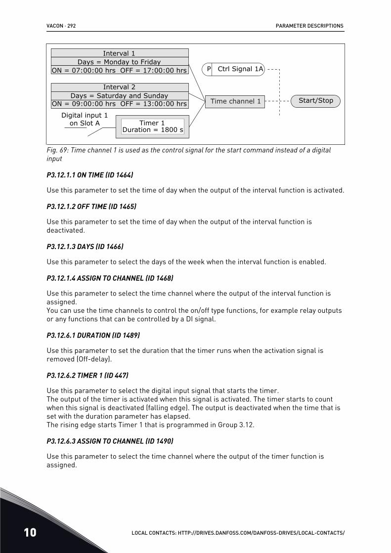
Interval 1Days = Monday to Friday
ON = 07:00:00 hrs OFF = 17:00:00 hrs
Interval 2Days = Saturday and Sunday
ON = 09:00:00 hrs OFF = 13:00:00 hrs
P Ctrl Signal 1A
Digital input 1 on Slot A Timer 1
Duration = 1800 s
Time channel 1 Start/Stop
Fig. 69: Time channel 1 is used as the control signal for the start command instead of a digitalinput
P3.12.1.1 ON TIME (ID 1464)
Use this parameter to set the time of day when the output of the interval function is activated.
P3.12.1.2 OFF TIME (ID 1465)
Use this parameter to set the time of day when the output of the interval function isdeactivated.
P3.12.1.3 DAYS (ID 1466)
Use this parameter to select the days of the week when the interval function is enabled.
P3.12.1.4 ASSIGN TO CHANNEL (ID 1468)
Use this parameter to select the time channel where the output of the interval function isassigned.You can use the time channels to control the on/off type functions, for example relay outputsor any functions that can be controlled by a DI signal.
P3.12.6.1 DURATION (ID 1489)
Use this parameter to set the duration that the timer runs when the activation signal isremoved (Off-delay).
P3.12.6.2 TIMER 1 (ID 447)
Use this parameter to select the digital input signal that starts the timer.The output of the timer is activated when this signal is activated. The timer starts to countwhen this signal is deactivated (falling edge). The output is deactivated when the time that isset with the duration parameter has elapsed.The rising edge starts Timer 1 that is programmed in Group 3.12.
P3.12.6.3 ASSIGN TO CHANNEL (ID 1490)
Use this parameter to select the time channel where the output of the timer function isassigned.
VACON · 292 PARAMETER DESCRIPTIONS
10 LOCAL CONTACTS: HTTP://DRIVES.DANFOSS.COM/DANFOSS-DRIVES/LOCAL-CONTACTS/
You can use the time channels to control the on/off type functions, for example relay outputsor any functions that can be controlled by a DI signal.
10.14 PID CONTROLLER
10.14.1 BASIC SETTINGS
P3.13.1.1 PID GAIN (ID 118)
Use this parameter to adjust the gain of the PID controller.If this parameter is set to 100%, a change of 10% in the error value causes the controlleroutput to change by 10%.
P3.13.1.2 PID INTEGRATION TIME (ID 119)
Use this parameter to adjust the integration time of the PID controller.If this parameter is set to 1.00 s, a change of 10% in the error value causes the controlleroutput to change by 10.00%/s.
P3.13.1.3 PID DERIVATION TIME (ID 132)
Use this parameter to adjust the derivation time of the PID controller.If this parameter is set to 1,00 s, a change of 10% in the error value during 1.00 s causes thecontroller output to change by 10.00%.
P3.13.1.4 PROCESS UNIT SELECTION (ID 1036)
Use this parameter to select the unit for the feedback and the setpoint signals of the PIDcontroller.Make a selection of the unit for the actual value.
P3.13.1.5 PROCESS UNIT MIN (ID 1033)
Use this parameter to set the minimum value of the PID feedback signal.For example, an analogue signal of 4...20 mA corresponds to the pressure of 0...10 bar.The value in process units at a 0% feedback or setpoint. This scaling is done for monitoringpurposes only. The PID controller still uses the percentage internally for feedbacks andsetpoints.
P3.13.1.6 PROCESS UNIT MAX (ID 1034)
Use this parameter to set the maximum value of the PID feedback signal.For example, an analogue signal of 4...20 mA corresponds to the pressure of 0...10 bar.The value in process units at a 0% feedback or setpoint. This scaling is done for monitoringpurposes only. The PID controller still uses the percentage internally for feedbacks andsetpoints.
P3.13.1.7 PROCESS UNIT DECIMALS (ID 1035)
Use this parameter to set the number of decimals for the process unit values.For example, an analogue signal of 4...20 mA corresponds to the pressure of 0...10 bar.
PARAMETER DESCRIPTIONS VACON · 293
LOCAL CONTACTS: HTTP://DRIVES.DANFOSS.COM/DANFOSS-DRIVES/LOCAL-CONTACTS/ 10
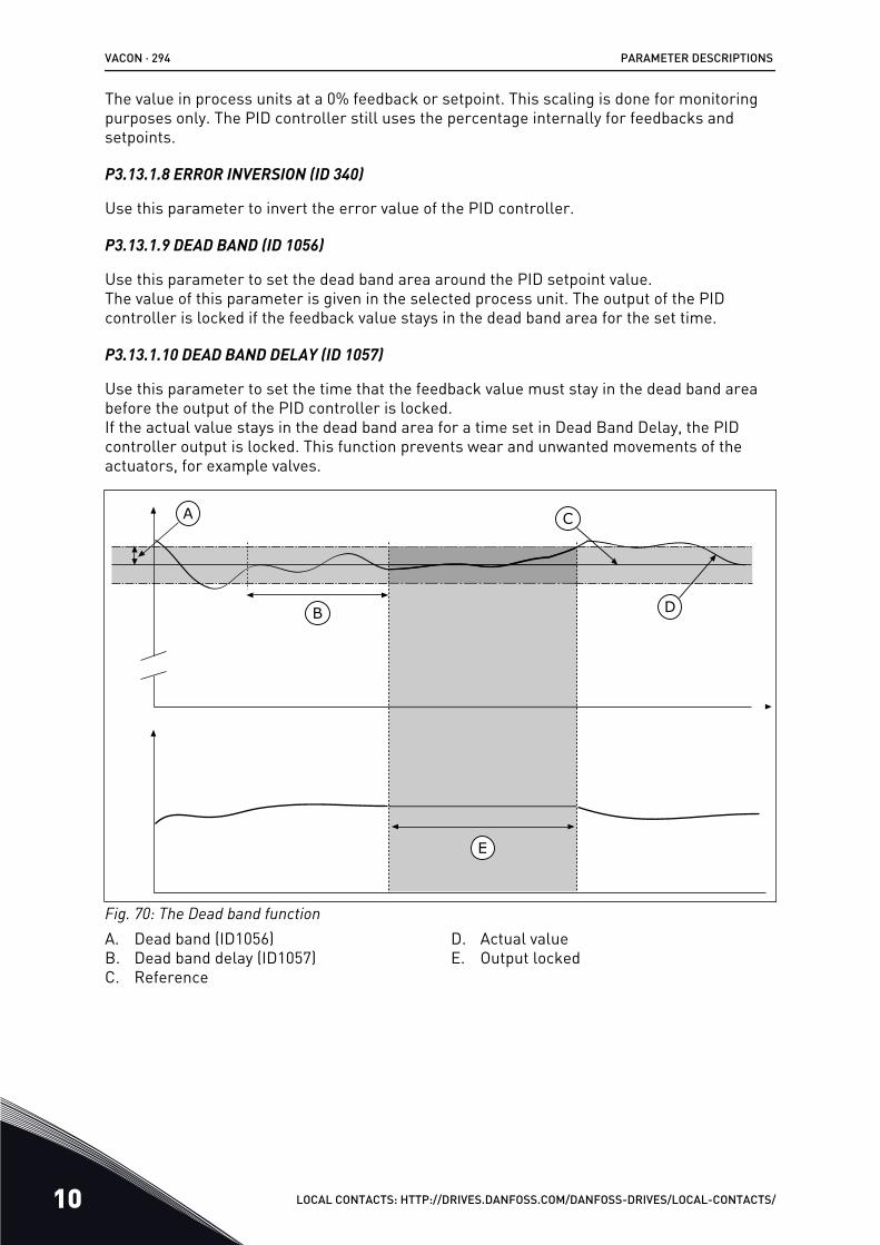
The value in process units at a 0% feedback or setpoint. This scaling is done for monitoringpurposes only. The PID controller still uses the percentage internally for feedbacks andsetpoints.
P3.13.1.8 ERROR INVERSION (ID 340)
Use this parameter to invert the error value of the PID controller.
P3.13.1.9 DEAD BAND (ID 1056)
Use this parameter to set the dead band area around the PID setpoint value.The value of this parameter is given in the selected process unit. The output of the PIDcontroller is locked if the feedback value stays in the dead band area for the set time.
P3.13.1.10 DEAD BAND DELAY (ID 1057)
Use this parameter to set the time that the feedback value must stay in the dead band areabefore the output of the PID controller is locked.If the actual value stays in the dead band area for a time set in Dead Band Delay, the PIDcontroller output is locked. This function prevents wear and unwanted movements of theactuators, for example valves.
A
B
C
D
E
Fig. 70: The Dead band functionA. Dead band (ID1056)B. Dead band delay (ID1057)C. Reference
D. Actual valueE. Output locked
VACON · 294 PARAMETER DESCRIPTIONS
10 LOCAL CONTACTS: HTTP://DRIVES.DANFOSS.COM/DANFOSS-DRIVES/LOCAL-CONTACTS/
10.14.2 SETPOINTS
P3.13.2.1 KEYPAD SETPOINT 1 (ID 167)
Use this parameter to set the setpoint value of the PID controller when the setpoint source is'Keypad SP'.The value of this parameter is given in the selected process unit.
P3.13.2.2 KEYPAD SETPOINT 2 (ID 168)
Use this parameter to set the setpoint value of the PID controller when the setpoint source is'Keypad SP'.The value of this parameter is given in the selected process unit.
P3.13.2.3 SETPOINT RAMP TIME (ID 1068)
Use this parameter to set the rising and falling ramp times for the setpoint changes.Ramp time is the time that is necessary for the setpoint value to change from minimum tomaximum. If the value of this parameter is set to 0, no ramps are used.
P3.13.2.4 PID SETPOINT BOOST ACTIVATION (ID 1046)
Use this parameter to select the digital input signal that activates the boost for the PIDsetpoint value.
P3.13.2.5 PID SETPOINT SELECTION (ID 1047)
Use this parameter to set the digital input signal that selects the PID setpoint value to beused.
P3.13.2.6 SETPOINT SOURCE 1 SELECTION (ID 332)
Use this parameter to select the source of the PID setpoint signal.The AIs and the ProcessDataIn are handled as percentages (0.00-100.00%) and scaledaccording to the setpoint minimum and maximum.
NOTE!
The ProcessDataIn signals use 2 decimals.If temperature inputs are selected, you must set the values of parameters P3.13.1.5 ProcessUnit Min and P3.13.1.6 Process Unit Max to correspond to the the scale of the temperaturemeasurement board: ProcessUnitMin = -50 °C and ProcessUnitMax = 200 °C.
P3.13.2.7 SETPOINT 1 MINIMUM (ID 1069)
Use this parameter to set the minimum value of the setpoint signal.
P3.13.2.8 SETPOINT 1 MAXIMUM (ID 1070)
Use this parameter to set the maximum value of the setpoint signal.
PARAMETER DESCRIPTIONS VACON · 295
LOCAL CONTACTS: HTTP://DRIVES.DANFOSS.COM/DANFOSS-DRIVES/LOCAL-CONTACTS/ 10
P3.13.2.9 SETPOINT 1 BOOST (ID 1071)
Use this parameter to set the multiplier for the setpoint boost function.When the setpoint boost command is given, the setpoint value is multiplied with the factorthat is set with this parameter.
10.14.3 FEEDBACK
P3.13.3.1 FEEDBACK FUNCTION (ID 333)
Use this parameter to select if the feedback value is taken from a single signal or combinedfrom two signals.You can select the mathematical function that is used when the two feedback signals arecombined.
P3.13.3.2 FEEDBACK FUNCTION GAIN (ID 1058)
Use this parameter to adjust the gain of the feedback signal.This parameter is used, for example, with the value 2 in Feedback Function.
P3.13.3.3 FEEDBACK 1 SOURCE SELECTION (ID 334)
Use this parameter to select the source of the PID feedback signal.The AIs and the ProcessDataIn are handled as percentages (0.00-100.00%) and scaledaccording to the feedback minimum and maximum.
NOTE!
The ProcessDataIn signals use 2 decimals.If temperature inputs are selected, you must set the values of parameters P3.13.1.5 ProcessUnit Min and P3.13.1.6 Process Unit Max to correspond to the the scale of the temperaturemeasurement board: ProcessUnitMin = -50 °C and ProcessUnitMax = 200 °C.
P3.13.3.4 FEEDBACK 1 MINIMUM (ID 336)
Use this parameter to set the minimum value of the feedback signal.
P3.13.3.5 FEEDBACK 1 MAXIMUM (ID 337)
Use this parameter to set the maximum value of the feedback signal.
10.14.4 FEEDFORWARD
P3.13.4.1 FEEDFORWARD FUNCTION (ID 1059)
Use this parameter to select if the feedforward value is taken from a single signal orcombined from two signals.You can select the mathematical function that is used when the two feedforward signals arecombined.
Accurate process models are usually necessary for the Feedforward function. In someconditions, a gain and offset type of feedforward is sufficient. The feedforward part does not
VACON · 296 PARAMETER DESCRIPTIONS
10 LOCAL CONTACTS: HTTP://DRIVES.DANFOSS.COM/DANFOSS-DRIVES/LOCAL-CONTACTS/
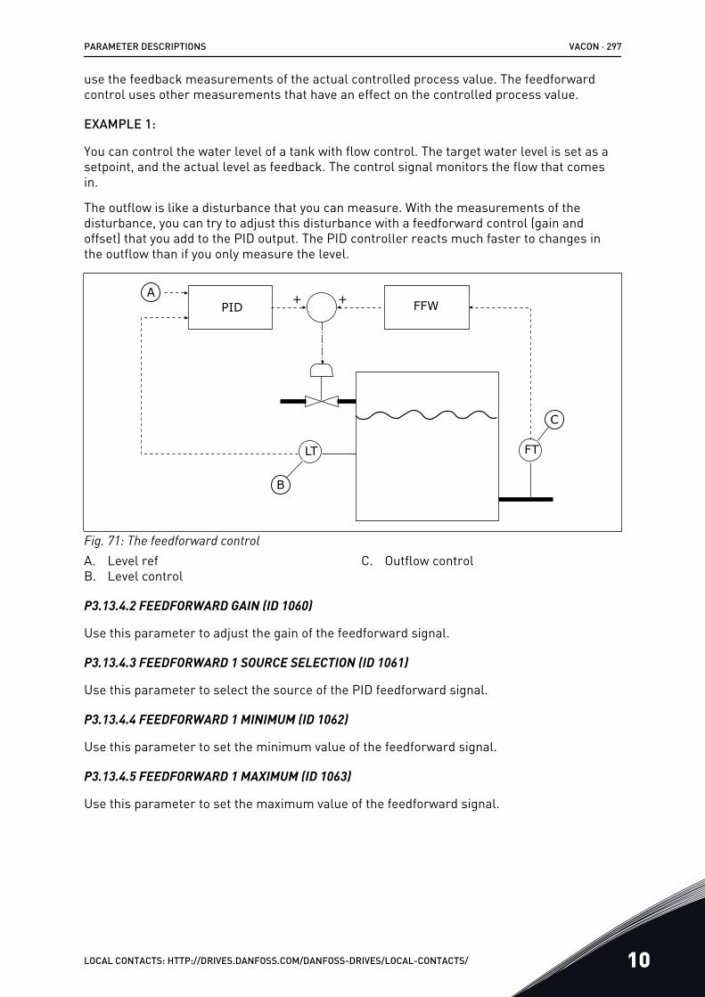
use the feedback measurements of the actual controlled process value. The feedforwardcontrol uses other measurements that have an effect on the controlled process value.
EXAMPLE 1:
You can control the water level of a tank with flow control. The target water level is set as asetpoint, and the actual level as feedback. The control signal monitors the flow that comesin.
The outflow is like a disturbance that you can measure. With the measurements of thedisturbance, you can try to adjust this disturbance with a feedforward control (gain andoffset) that you add to the PID output. The PID controller reacts much faster to changes inthe outflow than if you only measure the level.
+ +A
B
C
LT FT
PID FFW
Fig. 71: The feedforward controlA. Level refB. Level control
C. Outflow control
P3.13.4.2 FEEDFORWARD GAIN (ID 1060)
Use this parameter to adjust the gain of the feedforward signal.
P3.13.4.3 FEEDFORWARD 1 SOURCE SELECTION (ID 1061)
Use this parameter to select the source of the PID feedforward signal.
P3.13.4.4 FEEDFORWARD 1 MINIMUM (ID 1062)
Use this parameter to set the minimum value of the feedforward signal.
P3.13.4.5 FEEDFORWARD 1 MAXIMUM (ID 1063)
Use this parameter to set the maximum value of the feedforward signal.
PARAMETER DESCRIPTIONS VACON · 297
LOCAL CONTACTS: HTTP://DRIVES.DANFOSS.COM/DANFOSS-DRIVES/LOCAL-CONTACTS/ 10
10.14.5 SLEEP FUNCTION
P3.13.5.1 SP1 SLEEP FREQUENCY (ID 1016)
Use this parameter to set the limit below which the output frequency of the drive must stayfor a set time before the drive goes to the sleep state.
The value of this parameter is used when the signal of the PID controller setpoint is takenfrom the setpoint source 1.
Criteria for going to sleep mode
• Output frequency remains below sleep frequency for longer than defined sleep delaytime
• PID feedback signal remains above defined wake up level
Criteria for waking from sleep
• PID feedback signal falls below defined wake up level
NOTE!
A wrong set wake up level might not allow the drive to go into sleep mode
P3.13.5.2 SP1 SLEEP DELAY (ID 1017)
Use this parameter to set the minimum duration that the output frequency of the drive muststay below the set limit before the drive goes to the sleep state.The value of this parameter is used when the signal of the PID controller setpoint is takenfrom the setpoint source 1.
P3.13.5.3 SP1 WAKE-UP LEVEL (ID 1018)
Use this parameter to set the level at which the drive wakes up from the sleep state.When the PID feedback value goes below the level that is set with this parameter, drivewakes up from the sleep state. The operation of this parameter is selected with wake upmode parameter.
P3.13.5.4 SP1 WAKE-UP MODE (ID 1019)
Use this parameter to select the operation for the wake up level parameter.
The drive wakes up from the sleep mode when the value of PID Feedback goes below theWake-up level.
This parameter defines if Wake-up level is used as a static absolute level or as a relativelevel which follows PID setpoint value.
Selection 0 = Absolute level (The wake-up level is a static level that does not follow thesetpoint value.)Selection 1 = Relative setpoint (The wake-up level is an offset below the actual setpointvalue. The wake-up level follows the actual setpoint.)
VACON · 298 PARAMETER DESCRIPTIONS
10 LOCAL CONTACTS: HTTP://DRIVES.DANFOSS.COM/DANFOSS-DRIVES/LOCAL-CONTACTS/
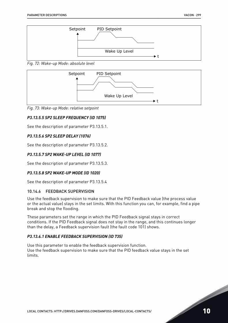
PID SetpointSetpoint
tWake Up Level
Fig. 72: Wake-up Mode: absolute level
PID SetpointSetpoint
tWake Up Level
Fig. 73: Wake-up Mode: relative setpoint
P3.13.5.5 SP2 SLEEP FREQUENCY (ID 1075)
See the description of parameter P3.13.5.1.
P3.13.5.6 SP2 SLEEP DELAY (1076)
See the description of parameter P3.13.5.2.
P3.13.5.7 SP2 WAKE-UP LEVEL (ID 1077)
See the description of parameter P3.13.5.3.
P3.13.5.8 SP2 WAKE-UP MODE (ID 1020)
See the description of parameter P3.13.5.4
10.14.6 FEEDBACK SUPERVISIONUse the feedback supervision to make sure that the PID Feedback value (the process valueor the actual value) stays in the set limits. With this function you can, for example, find a pipebreak and stop the flooding.
These parameters set the range in which the PID Feedback signal stays in correctconditions. If the PID Feedback signal does not stay in the range, and this continues longerthan the delay, a Feedback supervision fault (the fault code 101) shows.
P3.13.6.1 ENABLE FEEDBACK SUPERVISION (ID 735)
Use this parameter to enable the feedback supervision function.Use the feedback supervision to make sure that the PID feedback value stays in the setlimits.
PARAMETER DESCRIPTIONS VACON · 299
LOCAL CONTACTS: HTTP://DRIVES.DANFOSS.COM/DANFOSS-DRIVES/LOCAL-CONTACTS/ 10
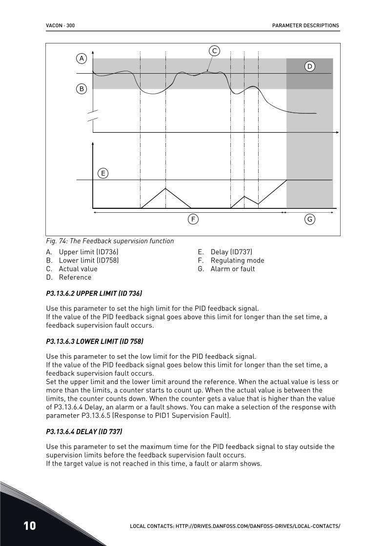
A
B
C
D
E
F G
Fig. 74: The Feedback supervision functionA. Upper limit (ID736)B. Lower limit (ID758)C. Actual valueD. Reference
E. Delay (ID737)F. Regulating modeG. Alarm or fault
P3.13.6.2 UPPER LIMIT (ID 736)
Use this parameter to set the high limit for the PID feedback signal.If the value of the PID feedback signal goes above this limit for longer than the set time, afeedback supervision fault occurs.
P3.13.6.3 LOWER LIMIT (ID 758)
Use this parameter to set the low limit for the PID feedback signal.If the value of the PID feedback signal goes below this limit for longer than the set time, afeedback supervision fault occurs.Set the upper limit and the lower limit around the reference. When the actual value is less ormore than the limits, a counter starts to count up. When the actual value is between thelimits, the counter counts down. When the counter gets a value that is higher than the valueof P3.13.6.4 Delay, an alarm or a fault shows. You can make a selection of the response withparameter P3.13.6.5 (Response to PID1 Supervision Fault).
P3.13.6.4 DELAY (ID 737)
Use this parameter to set the maximum time for the PID feedback signal to stay outside thesupervision limits before the feedback supervision fault occurs.If the target value is not reached in this time, a fault or alarm shows.
VACON · 300 PARAMETER DESCRIPTIONS
10 LOCAL CONTACTS: HTTP://DRIVES.DANFOSS.COM/DANFOSS-DRIVES/LOCAL-CONTACTS/
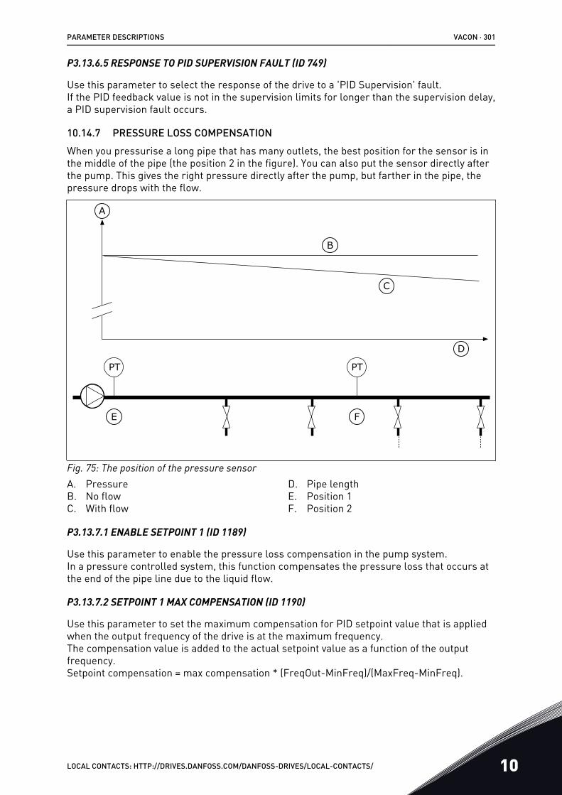
P3.13.6.5 RESPONSE TO PID SUPERVISION FAULT (ID 749)
Use this parameter to select the response of the drive to a 'PID Supervision' fault.If the PID feedback value is not in the supervision limits for longer than the supervision delay,a PID supervision fault occurs.
10.14.7 PRESSURE LOSS COMPENSATIONWhen you pressurise a long pipe that has many outlets, the best position for the sensor is inthe middle of the pipe (the position 2 in the figure). You can also put the sensor directly afterthe pump. This gives the right pressure directly after the pump, but farther in the pipe, thepressure drops with the flow.
PT PT
A
B
C
D
E F
Fig. 75: The position of the pressure sensorA. PressureB. No flowC. With flow
D. Pipe lengthE. Position 1F. Position 2
P3.13.7.1 ENABLE SETPOINT 1 (ID 1189)
Use this parameter to enable the pressure loss compensation in the pump system.In a pressure controlled system, this function compensates the pressure loss that occurs atthe end of the pipe line due to the liquid flow.
P3.13.7.2 SETPOINT 1 MAX COMPENSATION (ID 1190)
Use this parameter to set the maximum compensation for PID setpoint value that is appliedwhen the output frequency of the drive is at the maximum frequency.The compensation value is added to the actual setpoint value as a function of the outputfrequency.Setpoint compensation = max compensation * (FreqOut-MinFreq)/(MaxFreq-MinFreq).
PARAMETER DESCRIPTIONS VACON · 301
LOCAL CONTACTS: HTTP://DRIVES.DANFOSS.COM/DANFOSS-DRIVES/LOCAL-CONTACTS/ 10
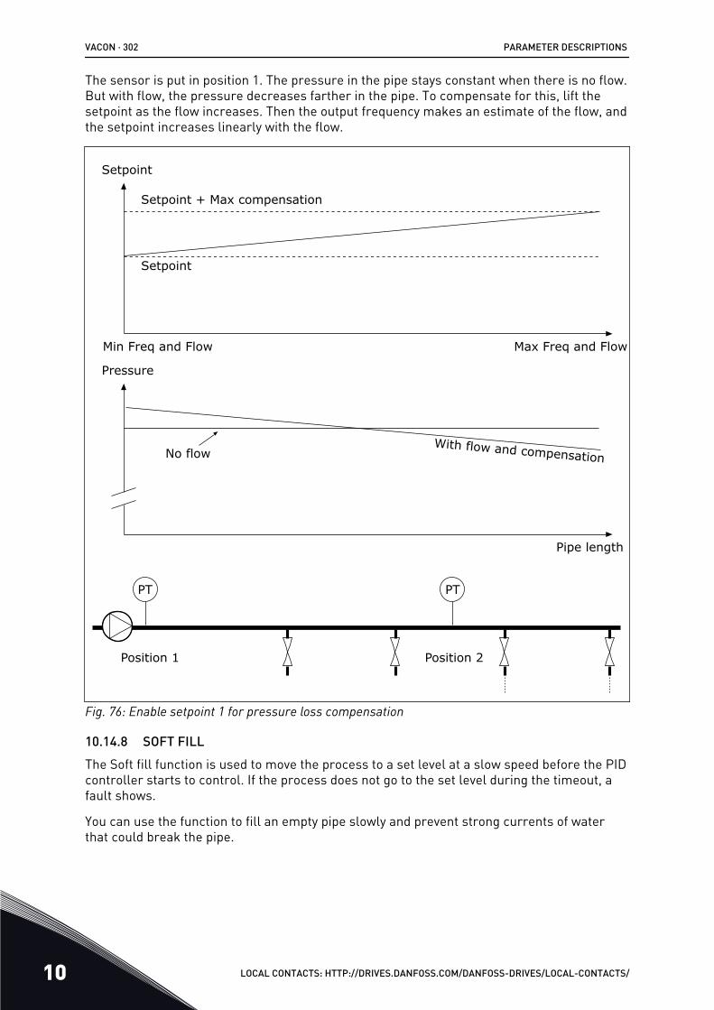
The sensor is put in position 1. The pressure in the pipe stays constant when there is no flow.But with flow, the pressure decreases farther in the pipe. To compensate for this, lift thesetpoint as the flow increases. Then the output frequency makes an estimate of the flow, andthe setpoint increases linearly with the flow.
With flow and compensation
Position 1 Position 2
Pressure
No flow
Pipe length
Setpoint
Max Freq and FlowMin Freq and Flow
Setpoint + Max compensation
Setpoint
PTPT
Fig. 76: Enable setpoint 1 for pressure loss compensation
10.14.8 SOFT FILLThe Soft fill function is used to move the process to a set level at a slow speed before the PIDcontroller starts to control. If the process does not go to the set level during the timeout, afault shows.
You can use the function to fill an empty pipe slowly and prevent strong currents of waterthat could break the pipe.
VACON · 302 PARAMETER DESCRIPTIONS
10 LOCAL CONTACTS: HTTP://DRIVES.DANFOSS.COM/DANFOSS-DRIVES/LOCAL-CONTACTS/
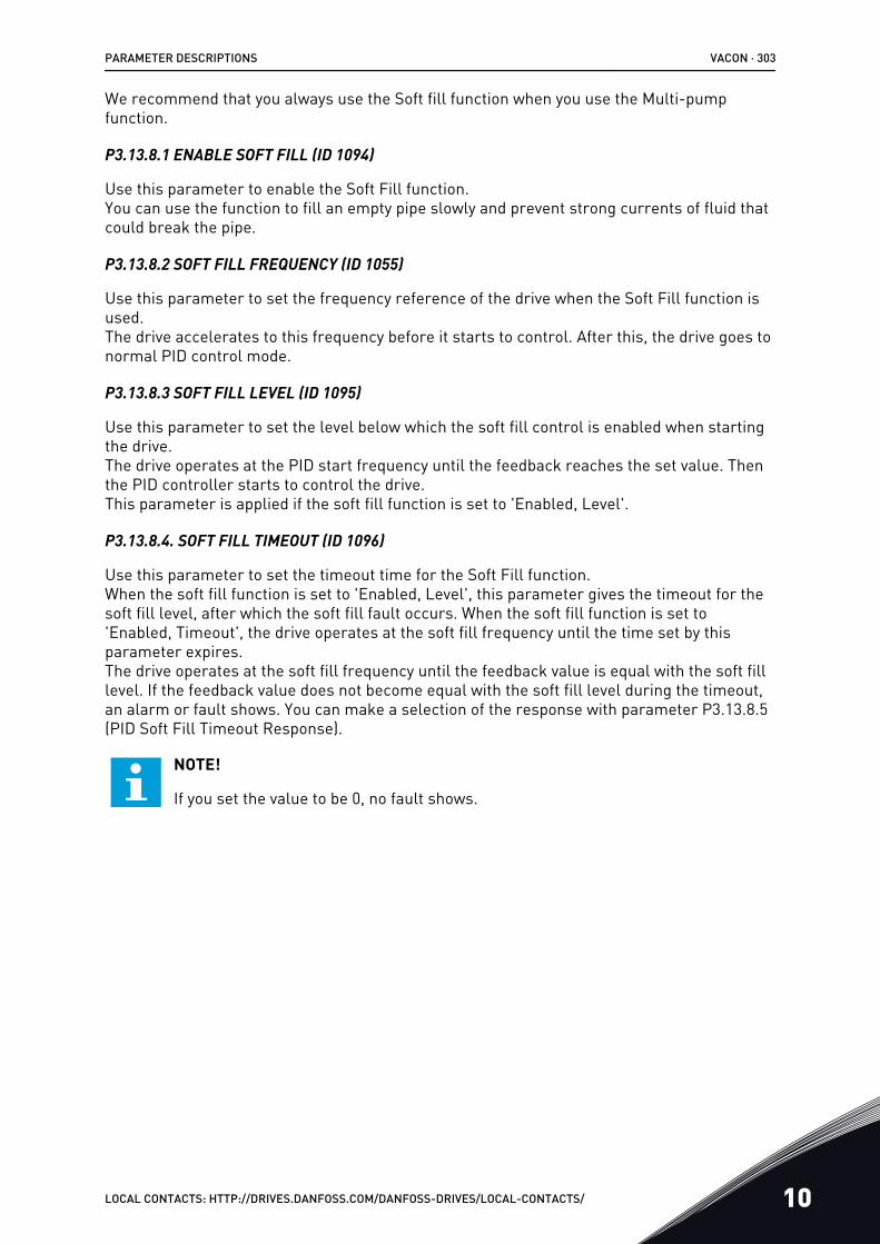
We recommend that you always use the Soft fill function when you use the Multi-pumpfunction.
P3.13.8.1 ENABLE SOFT FILL (ID 1094)
Use this parameter to enable the Soft Fill function.You can use the function to fill an empty pipe slowly and prevent strong currents of fluid thatcould break the pipe.
P3.13.8.2 SOFT FILL FREQUENCY (ID 1055)
Use this parameter to set the frequency reference of the drive when the Soft Fill function isused.The drive accelerates to this frequency before it starts to control. After this, the drive goes tonormal PID control mode.
P3.13.8.3 SOFT FILL LEVEL (ID 1095)
Use this parameter to set the level below which the soft fill control is enabled when startingthe drive.The drive operates at the PID start frequency until the feedback reaches the set value. Thenthe PID controller starts to control the drive.This parameter is applied if the soft fill function is set to 'Enabled, Level'.
P3.13.8.4. SOFT FILL TIMEOUT (ID 1096)
Use this parameter to set the timeout time for the Soft Fill function.When the soft fill function is set to 'Enabled, Level', this parameter gives the timeout for thesoft fill level, after which the soft fill fault occurs. When the soft fill function is set to'Enabled, Timeout', the drive operates at the soft fill frequency until the time set by thisparameter expires.The drive operates at the soft fill frequency until the feedback value is equal with the soft filllevel. If the feedback value does not become equal with the soft fill level during the timeout,an alarm or fault shows. You can make a selection of the response with parameter P3.13.8.5(PID Soft Fill Timeout Response).
NOTE!
If you set the value to be 0, no fault shows.
PARAMETER DESCRIPTIONS VACON · 303
LOCAL CONTACTS: HTTP://DRIVES.DANFOSS.COM/DANFOSS-DRIVES/LOCAL-CONTACTS/ 10
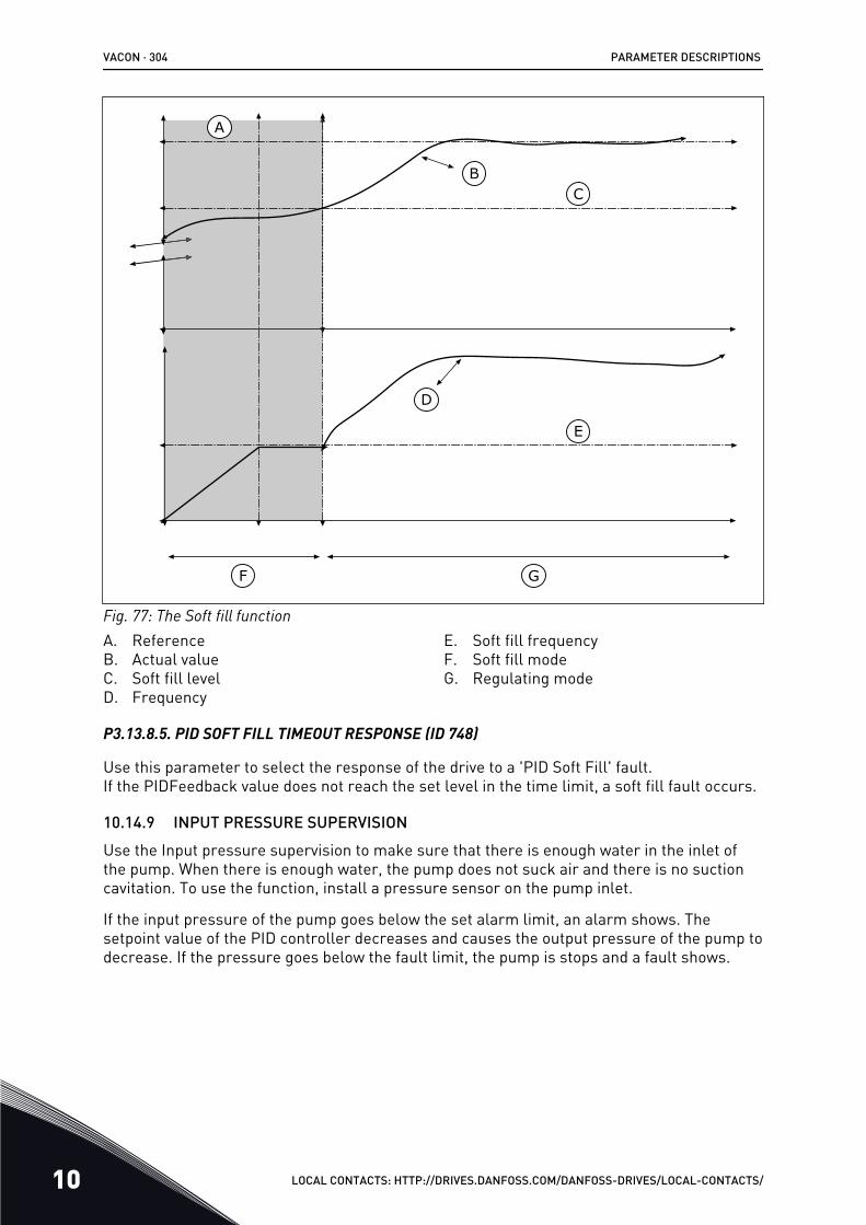
A
BC
D
E
F G
Fig. 77: The Soft fill functionA. ReferenceB. Actual valueC. Soft fill levelD. Frequency
E. Soft fill frequencyF. Soft fill modeG. Regulating mode
P3.13.8.5. PID SOFT FILL TIMEOUT RESPONSE (ID 748)
Use this parameter to select the response of the drive to a 'PID Soft Fill' fault.If the PIDFeedback value does not reach the set level in the time limit, a soft fill fault occurs.
10.14.9 INPUT PRESSURE SUPERVISIONUse the Input pressure supervision to make sure that there is enough water in the inlet ofthe pump. When there is enough water, the pump does not suck air and there is no suctioncavitation. To use the function, install a pressure sensor on the pump inlet.
If the input pressure of the pump goes below the set alarm limit, an alarm shows. Thesetpoint value of the PID controller decreases and causes the output pressure of the pump todecrease. If the pressure goes below the fault limit, the pump is stops and a fault shows.
VACON · 304 PARAMETER DESCRIPTIONS
10 LOCAL CONTACTS: HTTP://DRIVES.DANFOSS.COM/DANFOSS-DRIVES/LOCAL-CONTACTS/
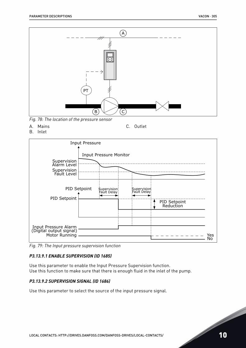
PT
A
B C
Fig. 78: The location of the pressure sensorA. MainsB. Inlet
C. Outlet
Input Pressure
SupervisionFault Level
Input Pressure Alarm(Digital output signal)
Supervision Alarm Level
Input Pressure Monitor
PID Setpoint
PID Setpoint
SupervisionFault Delay
SupervisionFault Delay
Motor Running YesNo
PID SetpointReduction
Fig. 79: The Input pressure supervision function
P3.13.9.1 ENABLE SUPERVISION (ID 1685)
Use this parameter to enable the Input Pressure Supervision function.Use this function to make sure that there is enough fluid in the inlet of the pump.
P3.13.9.2 SUPERVISION SIGNAL (ID 1686)
Use this parameter to select the source of the input pressure signal.
PARAMETER DESCRIPTIONS VACON · 305
LOCAL CONTACTS: HTTP://DRIVES.DANFOSS.COM/DANFOSS-DRIVES/LOCAL-CONTACTS/ 10
P3.13.9.3 SUPERVISION UNIT SELECTION (ID 1687)
Use this parameter to select the unit for the input pressure signal.You can scale the supervision signal (P3.13.9.2) to process units on the panel.
P3.13.9.4 SUPERVISION UNIT DECIMALS (ID 1688)
Use this parameter to set the number of decimals for the input pressure signal unit.You can scale the supervision signal (P3.13.9.2) to process units on the panel.
P3.13.9.5 SUPERVISION UNIT MINIMUM VALUE (ID 1689)
Use this parameter to set the minimum value of the input pressure signal.Enter the value in the selected process unit. For example, an analogue signal of 4...20 mAcorresponds to the pressure of 0...10 bar.
P3.13.9.6 SUPERVISION UNIT MAXIMUM VALUE (ID 1690)
Use this parameter to set the maximum value of the input pressure signal.Enter the value in the selected process unit. For example, an analogue signal of 4...20 mAcorresponds to the pressure of 0...10 bar.
P3.13.9.7 SUPERVISION ALARM LEVEL (ID 1691)
Use this parameter to set the limit for the input pressure alarm.If the measured input pressure goes below this limit, an input pressure alarm occurs.
P3.13.9.8 SUPERVISION FAULT LEVEL (ID 1692)
Use this parameter to set the limit for the input pressure fault.If the measured input pressure stays below this level for longer than the set time, an inputpressure fault occurs.
P3.13.9.9 SUPERVISION FAULT DELAY (ID 1693)
Use this parameter to set the maximum duration for the input pressure to stay below thefault limit before an input pressure fault occurs.
P3.13.9.10 PID SETPOINT REDUCTION (ID 1694)
Use this parameter to set the rate of the reduction of the PID setpoint value when themeasured input pressure is below the alarm limit.
10.14.10 FROST PROTECTIONUse the Frost protection function to protect the pump from frost damages. If the pump is insleep mode and the temperature that is measured in the pump goes below the set protectiontemperature, operate the pump at a constant frequency (that is set in P3.13.10.6 FrostProtection Frequency). To use the function, you must install a temperature transducer or atemperature sensor on the pump covering or on the pipe line near the pump.
P3.13.10.1 FROST PROTECTION (ID 1704)
Use this parameter to enable the Frost Protection function.
VACON · 306 PARAMETER DESCRIPTIONS
10 LOCAL CONTACTS: HTTP://DRIVES.DANFOSS.COM/DANFOSS-DRIVES/LOCAL-CONTACTS/
If the measured temperature of the pump goes below the set level and the drive is in sleepstate, the frost protection starts the pump to operate at a constant frequency.
P3.13.10.2 TEMPERATURE SIGNAL (ID 1705)
Use this parameter to select the source of the temperature signal that is used for the FrostProtection function.
P3.13.10.3 TEMPERATURE SIGNAL MINIMUM (ID 1706)
Use this parameter to set the minimum value of the temperature signal.For example, a temperature signal range of 4..20mA corresponds to the temperature of-50...200 celsius degrees.
P3.13.10.4 TEMPERATURE SIGNAL MAXIMUM (ID 1707)
Use this parameter to set the maximum value of the temperature signal.For example, a temperature signal range of 4..20mA corresponds to the temperature of-50...200 celsius degrees.
P3.13.10.5 FROST PROTECTION TEMPERATURE (ID 1708)
Use this parameter to set the temperature limit at which the drive starts.If the temperature of the pump goes below this limit and the drive is in the sleep state, thefrost protection function starts the drive.
P3.13.10.6 FROST PROTECTION FREQUENCY (ID 1710)
Use this parameter to set the frequency reference of the drive that is used when the frostprotection function is activated.
10.15 EXTERNAL PID CONTROLLER
P3.14.1.1 ENABLE EXTERNAL PID (ID 1630)
Use this parameter to enable the PID controller.
NOTE!
This controller is for external use only. It can be used with an analoque output.
P3.14.1.2 START SIGNAL (ID 1049)
Use this parameter to set the signal for starting and stopping the PID controller 2 forexternal usage.
NOTE!
If the PID2 controller is not enabled in the Basic menu for PID2, this parameter hasno effect.
PARAMETER DESCRIPTIONS VACON · 307
LOCAL CONTACTS: HTTP://DRIVES.DANFOSS.COM/DANFOSS-DRIVES/LOCAL-CONTACTS/ 10

P3.14.1.3 OUTPUT IN STOP (ID 1100)
Use this parameter to set the output value of the PID controller as a percentage of itsmaximum output value when it is stopped from a digital output.If the value of this parameter is set to 100%, a 10% change in the error value causes a 10%change in the controller output.
10.16 MULTI-PUMP FUNCTION
The Multi-pump function lets you control a maximum of 6 motors, pumps or fans with thePID controller.
The AC drive is connected to a motor, which is the regulating motor. The regulating motorconnects and disconnects the other motors to/from the mains with relays. This is done tokeep the right setpoint. The Autochange function controls the sequence in which the motorsstart to make sure that they wear equally. You can include the regulating motor in theautochange and interlock logic, or set it to always be Motor 1. It is possible to remove motorsmomentarily with the Interlock function, for example for maintenance.
M1
M2
A B
C
DE
G
FEF
Fig. 80: The Multi-pump functionA. BandwidthB. SetpointC. FeedbackD. Delay
E. ONF. OFFG. Drive is running at maximum or close to
maximum frequency
If the PID controller cannot keep the feedback in the set bandwidth, a motor or motors areconnected or disconnected.
VACON · 308 PARAMETER DESCRIPTIONS
10 LOCAL CONTACTS: HTTP://DRIVES.DANFOSS.COM/DANFOSS-DRIVES/LOCAL-CONTACTS/
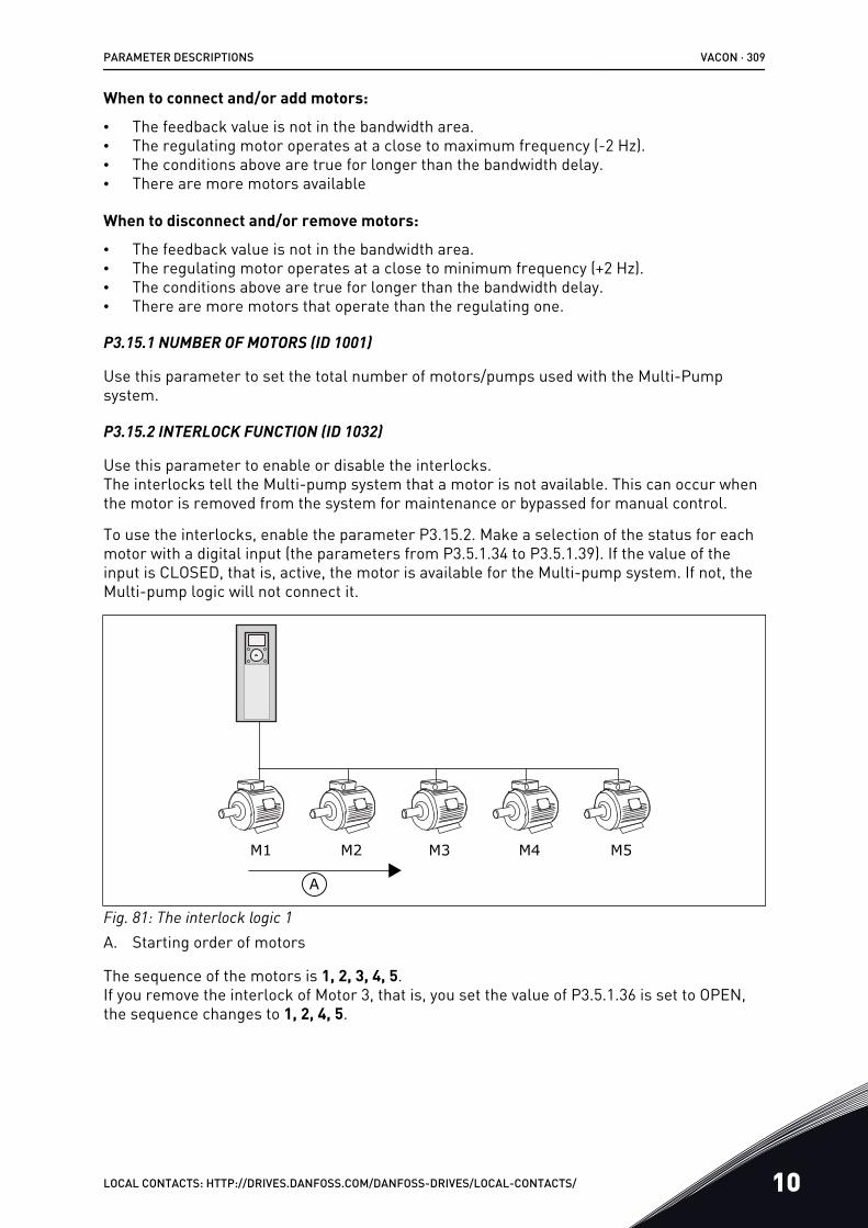
When to connect and/or add motors:
• The feedback value is not in the bandwidth area.• The regulating motor operates at a close to maximum frequency (-2 Hz).• The conditions above are true for longer than the bandwidth delay.• There are more motors available
When to disconnect and/or remove motors:
• The feedback value is not in the bandwidth area.• The regulating motor operates at a close to minimum frequency (+2 Hz).• The conditions above are true for longer than the bandwidth delay.• There are more motors that operate than the regulating one.
P3.15.1 NUMBER OF MOTORS (ID 1001)
Use this parameter to set the total number of motors/pumps used with the Multi-Pumpsystem.
P3.15.2 INTERLOCK FUNCTION (ID 1032)
Use this parameter to enable or disable the interlocks.The interlocks tell the Multi-pump system that a motor is not available. This can occur whenthe motor is removed from the system for maintenance or bypassed for manual control.
To use the interlocks, enable the parameter P3.15.2. Make a selection of the status for eachmotor with a digital input (the parameters from P3.5.1.34 to P3.5.1.39). If the value of theinput is CLOSED, that is, active, the motor is available for the Multi-pump system. If not, theMulti-pump logic will not connect it.
M1 M2 M3 M4 M5
A
Fig. 81: The interlock logic 1A. Starting order of motors
The sequence of the motors is 1, 2, 3, 4, 5.If you remove the interlock of Motor 3, that is, you set the value of P3.5.1.36 is set to OPEN,the sequence changes to 1, 2, 4, 5.
PARAMETER DESCRIPTIONS VACON · 309
LOCAL CONTACTS: HTTP://DRIVES.DANFOSS.COM/DANFOSS-DRIVES/LOCAL-CONTACTS/ 10
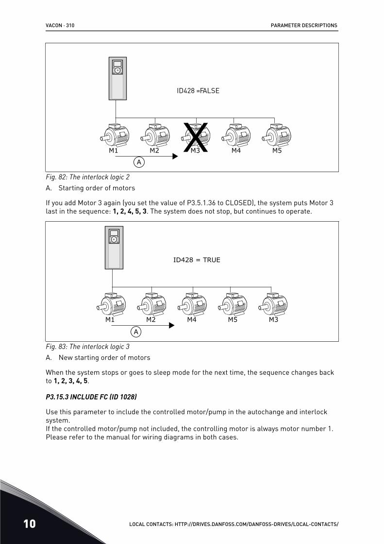
M1 M2 M3 M4 M5
A
ID428 =FALSE
Fig. 82: The interlock logic 2A. Starting order of motors
If you add Motor 3 again (you set the value of P3.5.1.36 to CLOSED), the system puts Motor 3last in the sequence: 1, 2, 4, 5, 3. The system does not stop, but continues to operate.
M1 M2 M4 M5 M3
A
ID428 = TRUE
Fig. 83: The interlock logic 3A. New starting order of motors
When the system stops or goes to sleep mode for the next time, the sequence changes backto 1, 2, 3, 4, 5.
P3.15.3 INCLUDE FC (ID 1028)
Use this parameter to include the controlled motor/pump in the autochange and interlocksystem.If the controlled motor/pump not included, the controlling motor is always motor number 1.Please refer to the manual for wiring diagrams in both cases.
VACON · 310 PARAMETER DESCRIPTIONS
10 LOCAL CONTACTS: HTTP://DRIVES.DANFOSS.COM/DANFOSS-DRIVES/LOCAL-CONTACTS/
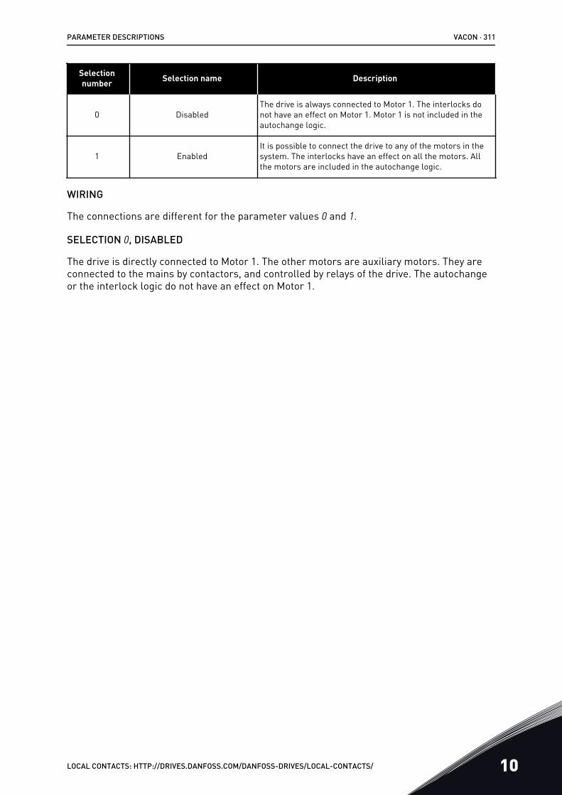
Selectionnumber Selection name Description
0 DisabledThe drive is always connected to Motor 1. The interlocks donot have an effect on Motor 1. Motor 1 is not included in theautochange logic.
1 EnabledIt is possible to connect the drive to any of the motors in thesystem. The interlocks have an effect on all the motors. Allthe motors are included in the autochange logic.
WIRING
The connections are different for the parameter values 0 and 1.
SELECTION 0, DISABLED
The drive is directly connected to Motor 1. The other motors are auxiliary motors. They areconnected to the mains by contactors, and controlled by relays of the drive. The autochangeor the interlock logic do not have an effect on Motor 1.
PARAMETER DESCRIPTIONS VACON · 311
LOCAL CONTACTS: HTTP://DRIVES.DANFOSS.COM/DANFOSS-DRIVES/LOCAL-CONTACTS/ 10

K2 K3
K2 K3
M1
Motor 1 control from relay Motor 2 control from relay Motor 3 control from relay
NOT USED
Mains
M2 M3
Fig. 84: Selection 0
SELECTION 1, ENABLED
To include the regulating motor in the autochange or in the interlock logic, obey theinstructions in the figure below. 1 relay controls each motor. The contactor logic alwaysconnects the first motor to the drive, and the next motors to the mains.
VACON · 312 PARAMETER DESCRIPTIONS
10 LOCAL CONTACTS: HTTP://DRIVES.DANFOSS.COM/DANFOSS-DRIVES/LOCAL-CONTACTS/
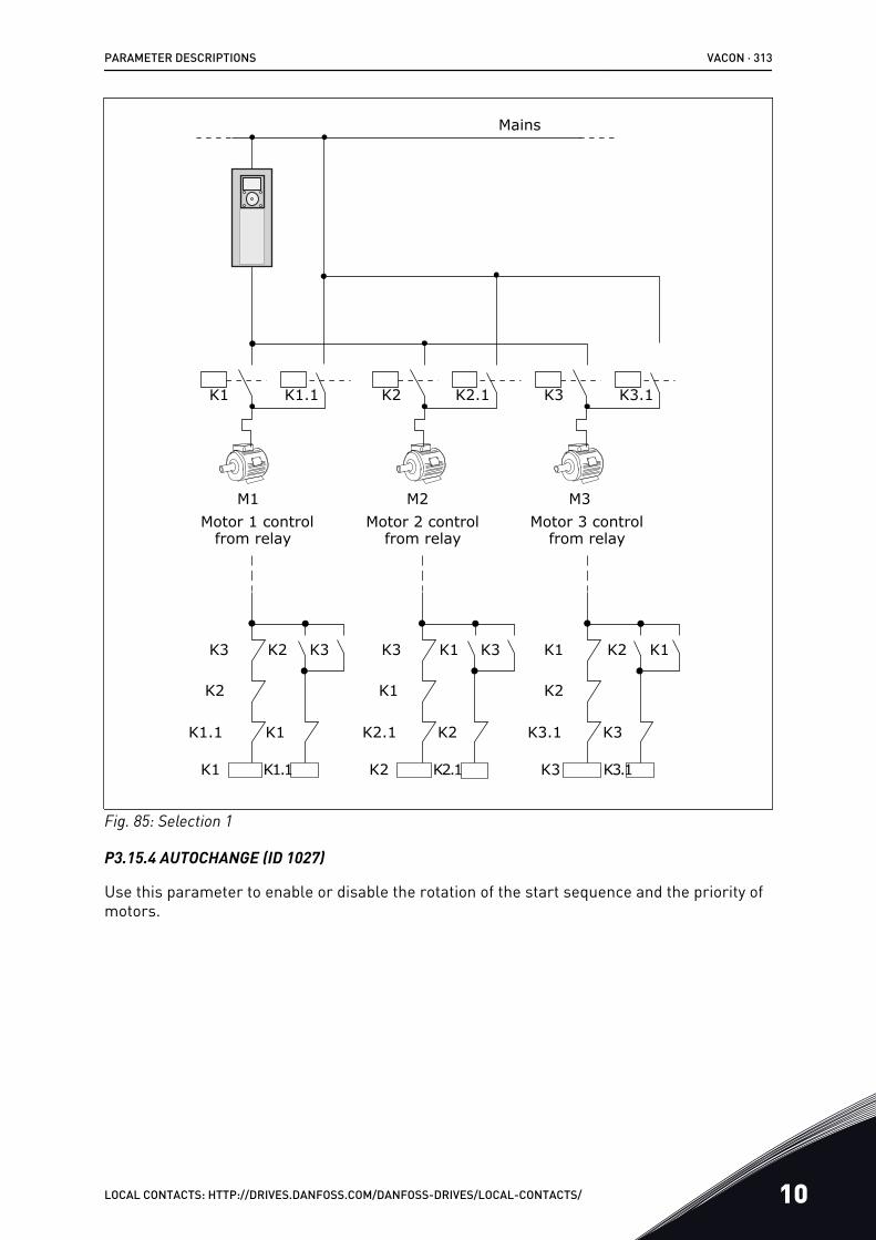
K1 K1.1 K2 K2.1 K3 K3.1
K1 K1.1 K2 K2.1 K3 K3.1
K1.1 K1
K2
K3 K2 K3 K3 K1 K3 K1 K2 K1
K2.1 K2
K1
K3.1 K3
K2
Mains
M1 M2 M3
from relayMotor 2 controlMotor 1 control
from relayMotor 3 control
from relay
Fig. 85: Selection 1
P3.15.4 AUTOCHANGE (ID 1027)
Use this parameter to enable or disable the rotation of the start sequence and the priority ofmotors.
PARAMETER DESCRIPTIONS VACON · 313
LOCAL CONTACTS: HTTP://DRIVES.DANFOSS.COM/DANFOSS-DRIVES/LOCAL-CONTACTS/ 10
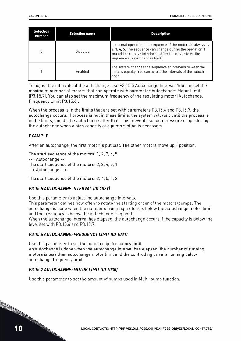
Selectionnumber Selection name Description
0 Disabled
In normal operation, the sequence of the motors is always 1,2, 3, 4, 5. The sequence can change during the operation ifyou add or remove interlocks. After the drive stops, thesequence always changes back.
1 EnabledThe system changes the sequence at intervals to wear themotors equally. You can adjust the intervals of the autoch-ange.
To adjust the intervals of the autochange, use P3.15.5 Autochange Interval. You can set themaximum number of motors that can operate with parameter Autochange: Motor Limit(P3.15.7). You can also set the maximum frequency of the regulating motor (Autochange:Frequency Limit P3.15.6).
When the process is in the limits that are set with parameters P3.15.6 and P3.15.7, theautochange occurs. If process is not in these limits, the system will wait until the process isin the limits, and do the autochange after that. This prevents sudden pressure drops duringthe autochange when a high capacity at a pump station is necessary.
EXAMPLE
After an autochange, the first motor is put last. The other motors move up 1 position.
The start sequence of the motors: 1, 2, 3, 4, 5--> Autochange -->The start sequence of the motors: 2, 3, 4, 5, 1--> Autochange -->
The start sequence of the motors: 3, 4, 5, 1, 2
P3.15.5 AUTOCHANGE INTERVAL (ID 1029)
Use this parameter to adjust the autochange intervals.This parameter defines how often to rotate the starting order of the motors/pumps. Theautochange is done when the number of running motors is below the autochange motor limitand the frequency is below the autochange freq limit.When the autochange interval has elapsed, the autochange occurs if the capacity is below thelevel set with P3.15.6 and P3.15.7.
P3.15.6 AUTOCHANGE: FREQUENCY LIMIT (ID 1031)
Use this parameter to set the autochange frequency limit.An autochange is done when the autochange interval has elapsed, the number of runningmotors is less than autochange motor limit and the controlling drive is running belowautochange frequency limit.
P3.15.7 AUTOCHANGE: MOTOR LIMIT (ID 1030)
Use this parameter to set the amount of pumps used in Multi-pump function.
VACON · 314 PARAMETER DESCRIPTIONS
10 LOCAL CONTACTS: HTTP://DRIVES.DANFOSS.COM/DANFOSS-DRIVES/LOCAL-CONTACTS/
An autochange is done when the autochange interval has elapsed, the number of runningmotors is less than autochange motor limit and the controlling drive is running belowautochange frequency limit.
P3.15.8 BANDWIDTH (ID 1097)
Use this parameter to set the bandwith area around the PID setpoint for starting andstopping of the auxiliary motors.When the PID feedback value stays in the bandwith area, the auxiliary motors does not startor stop. The value of this parameter is given as a percentage of the setpoint.For example, if setpoint = 5 bar, bandwidth = 10%. When the feedback value stays between4.5 and 5.5 bar, the motor is not disconnected or removed.
P3.15.9 BANDWIDTH DELAY (ID 1098)
Use this parameter to set the duration before the auxiliary motors start or stop.When the PID feedback is outside the bandwidth area, the time that is set with thisparameter must elapse befoforeyou can add or remove pumps.
P3.15.10 MOTOR 1 INTERLOCK (ID 426)
Use this parameter to select the digital input signal that is used as interlock signal for theMulti-Pump system.
10.16.1 OVERPRESSURE SUPERVISION
P3.15.16.1 ENABLE OVERPRESSURE SUPERVISION (ID 1698)
Use this parameter to enable the Overpressure supervision.If the PID feedback becomes higher than the set overpressure limit, all auxiliary motorsstops immediately. Only the regulating motor continues to operate.
You can use the Overpressure supervision function in a Multi-pump system. For example,when you close the primary valve of the pump system quickly, the pressure in the pipe linesincreases. The pressure can increase too quickly for the PID controller. To prevent that thepipes break, the overpressure supervision stops the auxiliary motors in the Multi-pumpsystem.
The overpressure supervision monitors the feedback signal of the PID controller, that is, thepressure. If the signal becomes higher than the overpressure level, it stops all the auxiliarypumps immediately. Only the regulating motor continues to operate. When the pressuredecreases, the system continues to operate, and connects the auxiliary motors again one at atime.
PARAMETER DESCRIPTIONS VACON · 315
LOCAL CONTACTS: HTTP://DRIVES.DANFOSS.COM/DANFOSS-DRIVES/LOCAL-CONTACTS/ 10
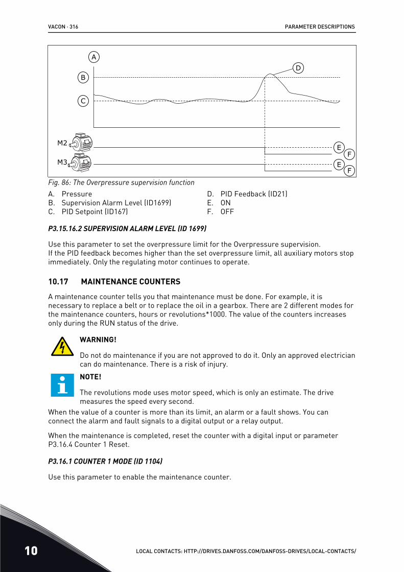
M2
M3
A
B
C
D
FE
E
F
Fig. 86: The Overpressure supervision functionA. PressureB. Supervision Alarm Level (ID1699)C. PID Setpoint (ID167)
D. PID Feedback (ID21)E. ONF. OFF
P3.15.16.2 SUPERVISION ALARM LEVEL (ID 1699)
Use this parameter to set the overpressure limit for the Overpressure supervision.If the PID feedback becomes higher than the set overpressure limit, all auxiliary motors stopimmediately. Only the regulating motor continues to operate.
10.17 MAINTENANCE COUNTERS
A maintenance counter tells you that maintenance must be done. For example, it isnecessary to replace a belt or to replace the oil in a gearbox. There are 2 different modes forthe maintenance counters, hours or revolutions*1000. The value of the counters increasesonly during the RUN status of the drive.
WARNING!
Do not do maintenance if you are not approved to do it. Only an approved electriciancan do maintenance. There is a risk of injury.NOTE!
The revolutions mode uses motor speed, which is only an estimate. The drivemeasures the speed every second.
When the value of a counter is more than its limit, an alarm or a fault shows. You canconnect the alarm and fault signals to a digital output or a relay output.
When the maintenance is completed, reset the counter with a digital input or parameterP3.16.4 Counter 1 Reset.
P3.16.1 COUNTER 1 MODE (ID 1104)
Use this parameter to enable the maintenance counter.
VACON · 316 PARAMETER DESCRIPTIONS
10 LOCAL CONTACTS: HTTP://DRIVES.DANFOSS.COM/DANFOSS-DRIVES/LOCAL-CONTACTS/
A maintenance counter tells you that the maintenance must be done when the counter valuegoes above the set limit.
P3.16.2 COUNTER 1 ALARM LIMIT (ID 1105)
Use this parameter to set the alarm limit for the maintenance counter.When the value of the counter goes above this limit, a maintenance alarm occurs.
P3.16.3 COUNTER 1 FAULT LIMIT (ID 1106)
Use this parameter to set the fault limit for the maintenance counter.When the value of the counter goes above this limit, a maintenance fault occurs.
P3.16.4 COUNTER 1 RESET (ID 1107)
Use this parameter to reset the maintenance counter.
P3.16.5 COUNTER 1 DI RESET (ID 490)
Use this parameter to select the digital input that resets the value of the MaintenanceCounter.
10.18 FIRE MODE
When Fire mode is active, the drive resets all faults that occur and continues to operate atthe same speed until it is not possible. The drive ignores all commands from the keypad,fieldbuses, and the PC tool. It only obeys the signals Fire Mode Activation, Fire ModeReverse, Run Enable, Run Interlock 1, and Run Interlock 2 from I/O.
The Fire mode function has 2 modes, the Test mode and the Enabled mode. To make aselection of a mode, write a password in parameter P3.17.1 (Fire Mode Password). In theTest mode, the drive does not automatically reset the faults, and the drive stops when a faultoccurs.
It is also possible to configure Fire mode with the Fire mode wizard, which you can activate inthe Quick Setup menu with parameter B1.1.4.
When you activate the Fire mode function, an alarm shows on the display.
CAUTION!
The warranty is void if the Fire mode function is activated! You can use Test modeto test the Fire mode function and the warranty stays valid.
P3.17.1 FIRE MODE PASSWORD (ID 1599)
Use this parameter to enable the Fire Mode function.
NOTE!
All other Fire Mode parameters will be locked when the Fire Mode is enabled andcorrect password is set in this parameter.
PARAMETER DESCRIPTIONS VACON · 317
LOCAL CONTACTS: HTTP://DRIVES.DANFOSS.COM/DANFOSS-DRIVES/LOCAL-CONTACTS/ 10
Selectionnumber Selection name Description
1002 Enabled mode The drive resets all the faults and continues to operate at thesame speed until it is not possible
1234 Test mode The drive does not automatically reset the faults, and thedrive stops when a fault occurs.
P3.17.2 FIRE MODE FREQUENCY SOURCE (ID 1617)
Use this parameter to select the frequency reference source when the Fire mode is active.This parameter enables the selection of, for example, the AI1 or the PID controller as thereference source when you operate the Fire mode.
P3.17.3 FIRE MODE FREQUENCY (ID 1598)
Use this parameter to set the frequency that is used when Fire mode is active.The drive uses this frequency when the value of parameter P3.17.2 Fire Mode FrequencySource is Fire Mode Frequency.
P3.17.4 FIRE MODE ACTIVATION ON OPEN (ID 1596)
Use this parameter to select the digital input signal that activates the Fire Mode function.If this digital input signal is activated, an alarm shows on the display, and the warrantybecomes void. The type of this digital input signal is NC (normally closed).
It is possible to try the Fire mode with the password that activates the Test mode. Then thewarranty stays valid.
NOTE!
If Fire mode is enabled, and you give the correct password to the parameter FireMode Password, all the Fire mode parameters become locked. To change the Firemode parameters, change the value of P3.17.1 Fire Mode Password to 0 first.
VACON · 318 PARAMETER DESCRIPTIONS
10 LOCAL CONTACTS: HTTP://DRIVES.DANFOSS.COM/DANFOSS-DRIVES/LOCAL-CONTACTS/
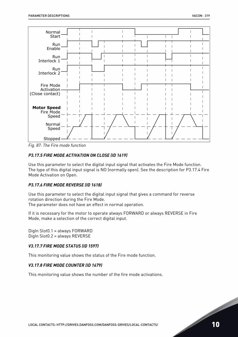
NormalStart
RunEnable
RunInterlock 2
Fire ModeActivation
(Close contact)
Motor Speed
Stopped
NormalSpeed
Fire ModeSpeed
RunInterlock 1
Fig. 87: The Fire mode function
P3.17.5 FIRE MODE ACTIVATION ON CLOSE (ID 1619)
Use this parameter to select the digital input signal that activates the Fire Mode function.The type of this digital input signal is NO (normally open). See the description for P3.17.4 FireMode Activation on Open.
P3.17.6 FIRE MODE REVERSE (ID 1618)
Use this parameter to select the digital input signal that gives a command for reverserotation direction during the Fire Mode.The parameter does not have an effect in normal operation.
If it is necessary for the motor to operate always FORWARD or always REVERSE in FireMode, make a selection of the correct digital input.
DigIn Slot0.1 = always FORWARDDigIn Slot0.2 = always REVERSE
V3.17.7 FIRE MODE STATUS (ID 1597)
This monitoring value shows the status of the Fire mode function.
V3.17.8 FIRE MODE COUNTER (ID 1679)
This monitoring value shows the number of the fire mode activations.
PARAMETER DESCRIPTIONS VACON · 319
LOCAL CONTACTS: HTTP://DRIVES.DANFOSS.COM/DANFOSS-DRIVES/LOCAL-CONTACTS/ 10
NOTE!
You can not reset the counter.
P3.17.9 FIRE MODE RUN INDICATION CURRENT (ID 15580)
Use this parameter to set the current limit for the run indication signal of the relay output.
This parameter only has effect if the value "Run indication" is selected for a relay output andthe Fire mode is active. The "Run indication" relay output function tells quickly if current issupplied to the motor during a fire.
The value of this parameter is the percentage counted from the motor nominal current. Ifthere is a fire and the current that is supplied to the motor is more than the nominal currenttimes the value of this parameter, the relay output closes.
For example, if parameter Motor Nominal Current has the value 5 A, and you set 20% as thedefault value of this parameter, the relay output closes and Fire Mode activates when theoutput current goes to 1 A.
NOTE!
This parameter does not have an effect if the Fire mode is not active. In normaloperation, if you select "Run indication" for a relay output, the result is the same aswhen "Run" is selected for the relay output.
10.19 MOTOR PREHEAT FUNCTION
P3.18.1 MOTOR PREHEAT FUNCTION (ID 1225)
Use this parameter to enable or disable the Motor Preheat function.The Motor preheat function keeps the drive and the motor warm during the STOP status. Inthe motor preheat, the system gives the motor a DC current. The motor preheat prevents forexample condensation.
VACON · 320 PARAMETER DESCRIPTIONS
10 LOCAL CONTACTS: HTTP://DRIVES.DANFOSS.COM/DANFOSS-DRIVES/LOCAL-CONTACTS/
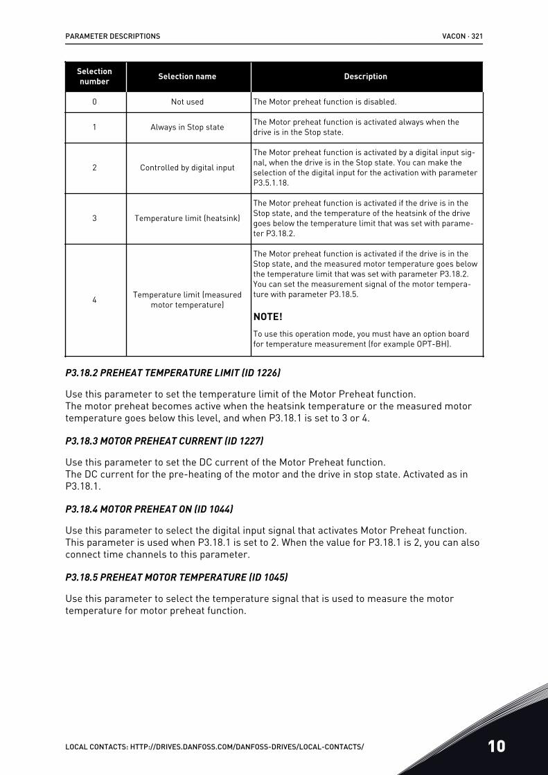
Selectionnumber Selection name Description
0 Not used The Motor preheat function is disabled.
1 Always in Stop state The Motor preheat function is activated always when thedrive is in the Stop state.
2 Controlled by digital input
The Motor preheat function is activated by a digital input sig-nal, when the drive is in the Stop state. You can make theselection of the digital input for the activation with parameterP3.5.1.18.
3 Temperature limit (heatsink)
The Motor preheat function is activated if the drive is in theStop state, and the temperature of the heatsink of the drivegoes below the temperature limit that was set with parame-ter P3.18.2.
4 Temperature limit (measuredmotor temperature)
The Motor preheat function is activated if the drive is in theStop state, and the measured motor temperature goes belowthe temperature limit that was set with parameter P3.18.2.You can set the measurement signal of the motor tempera-ture with parameter P3.18.5.
NOTE!To use this operation mode, you must have an option boardfor temperature measurement (for example OPT-BH).
P3.18.2 PREHEAT TEMPERATURE LIMIT (ID 1226)
Use this parameter to set the temperature limit of the Motor Preheat function.The motor preheat becomes active when the heatsink temperature or the measured motortemperature goes below this level, and when P3.18.1 is set to 3 or 4.
P3.18.3 MOTOR PREHEAT CURRENT (ID 1227)
Use this parameter to set the DC current of the Motor Preheat function.The DC current for the pre-heating of the motor and the drive in stop state. Activated as inP3.18.1.
P3.18.4 MOTOR PREHEAT ON (ID 1044)
Use this parameter to select the digital input signal that activates Motor Preheat function.This parameter is used when P3.18.1 is set to 2. When the value for P3.18.1 is 2, you can alsoconnect time channels to this parameter.
P3.18.5 PREHEAT MOTOR TEMPERATURE (ID 1045)
Use this parameter to select the temperature signal that is used to measure the motortemperature for motor preheat function.
PARAMETER DESCRIPTIONS VACON · 321
LOCAL CONTACTS: HTTP://DRIVES.DANFOSS.COM/DANFOSS-DRIVES/LOCAL-CONTACTS/ 10
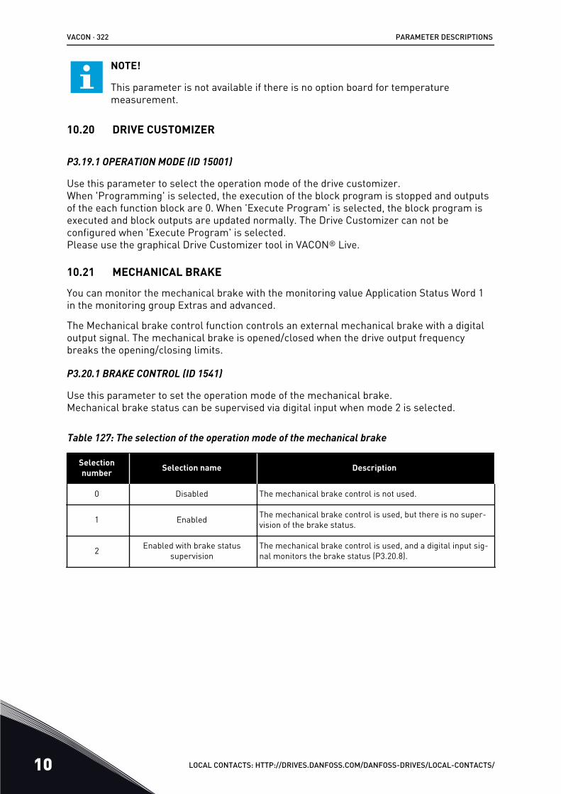
NOTE!
This parameter is not available if there is no option board for temperaturemeasurement.
10.20 DRIVE CUSTOMIZER
P3.19.1 OPERATION MODE (ID 15001)
Use this parameter to select the operation mode of the drive customizer.When 'Programming' is selected, the execution of the block program is stopped and outputsof the each function block are 0. When 'Execute Program' is selected, the block program isexecuted and block outputs are updated normally. The Drive Customizer can not beconfigured when 'Execute Program' is selected.Please use the graphical Drive Customizer tool in VACON® Live.
10.21 MECHANICAL BRAKE
You can monitor the mechanical brake with the monitoring value Application Status Word 1in the monitoring group Extras and advanced.
The Mechanical brake control function controls an external mechanical brake with a digitaloutput signal. The mechanical brake is opened/closed when the drive output frequencybreaks the opening/closing limits.
P3.20.1 BRAKE CONTROL (ID 1541)
Use this parameter to set the operation mode of the mechanical brake.Mechanical brake status can be supervised via digital input when mode 2 is selected.
Table 127: The selection of the operation mode of the mechanical brake
Selectionnumber Selection name Description
0 Disabled The mechanical brake control is not used.
1 Enabled The mechanical brake control is used, but there is no super-vision of the brake status.
2 Enabled with brake statussupervision
The mechanical brake control is used, and a digital input sig-nal monitors the brake status (P3.20.8).
VACON · 322 PARAMETER DESCRIPTIONS
10 LOCAL CONTACTS: HTTP://DRIVES.DANFOSS.COM/DANFOSS-DRIVES/LOCAL-CONTACTS/
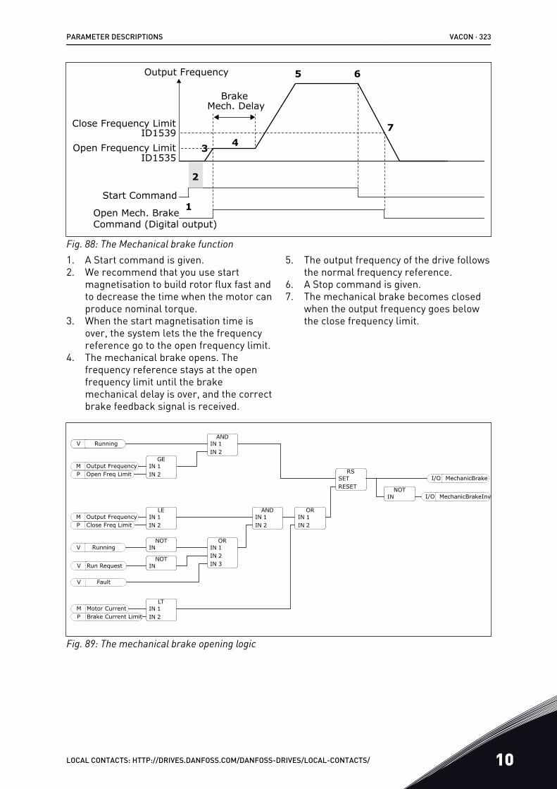
Close Frequency Limit
Output Frequency
Open Frequency Limit
BrakeMech. Delay
Open Mech. Brake Command (Digital output)
Start Command
ID1539
ID1535
1
2
3
5
4
6
7
Fig. 88: The Mechanical brake function1. A Start command is given.2. We recommend that you use start
magnetisation to build rotor flux fast andto decrease the time when the motor canproduce nominal torque.
3. When the start magnetisation time isover, the system lets the the frequencyreference go to the open frequency limit.
4. The mechanical brake opens. Thefrequency reference stays at the openfrequency limit until the brakemechanical delay is over, and the correctbrake feedback signal is received.
5. The output frequency of the drive followsthe normal frequency reference.
6. A Stop command is given.7. The mechanical brake becomes closed
when the output frequency goes belowthe close frequency limit.
SETRESET
ININ
ININOpen Freq Limit
Output Frequency
ININClose Freq Limit
Output Frequency
IN
IN
Running
Running
Run Request
Fault
INININ
ININ
ININ
ININ
Motor CurrentBrake Current Limit
MechanicBrake
MechanicBrakeInvIN
P
I/O
I/ONOT
RS
AND12
GE12P
M
V
LE12P
M
NOT
NOT
V
V
V
OR123
AND12
OR12
LT12
M
Fig. 89: The mechanical brake opening logic
PARAMETER DESCRIPTIONS VACON · 323
LOCAL CONTACTS: HTTP://DRIVES.DANFOSS.COM/DANFOSS-DRIVES/LOCAL-CONTACTS/ 10
P3.20.2 BRAKE MECHANICAL DELAY (ID 353)
Use this parameter to set the mechanical delay that is necessary to open the brake.After the brake opening command is given, the speed stays at the value of the parameterP3.20.3 (Brake Opening Frequency Limit) until the brake mechanical delay is expired. Set thedelay time to agree with the reaction time of the mechanical brake.
The Brake mechanical delay function is used to prevent current and/or torque spikes. Thisprevents the motor from operating at full speed against the brake. If you use P3.20.2 at thesame time with P3.20.8, it is necessary to have the expired delay and the feedback signal torelease the speed reference.
P3.20.3 BRAKE OPENING FREQUENCY LIMIT (ID 1535)
Use this parameter to set the frequency limit for opening the mechanical brake.The value of the parameter P3.20.3 is the output frequency limit of the drive to open themechanical brake. In open loop control, we recommend that you use a value that is equal tothe nominal slip of the motor.
The output frequency of the drive stays at this level until the brake mechanical delay isexpired, and the system receives the correct brake feedback signal.
P3.20.4 BRAKE CLOSING FREQUENCY LIMIT (ID 1539)
Use this parameter to set the frequency limit for closing the mechanical brake.The value of the parameter P3.20.4 is the output frequency limit of the drive to close themechanical brake. The drive stops and the output frequency goes near 0. You can use theparameter for the 2 directions, positive and negative.
P3.20.5 BRAKE CURRENT LIMIT (ID 1085)
Use this parameter to set the brake current limit.The Mechanical brake closes immediately if the motor current is below the limit set inparameter Brake Current Limit. We recommend that you set the value to approximately halfof the magnetisation current.
When the drive operates on the field weakening area, the brake current limit decreasesautomatically as a function of output frequency.
VACON · 324 PARAMETER DESCRIPTIONS
10 LOCAL CONTACTS: HTTP://DRIVES.DANFOSS.COM/DANFOSS-DRIVES/LOCAL-CONTACTS/
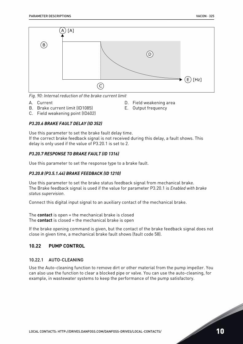
A
B
D
CE [Hz]
[A]
Fig. 90: Internal reduction of the brake current limitA. CurrentB. Brake current limit (ID1085)C. Field weakening point (ID602)
D. Field weakening areaE. Output frequency
P3.20.6 BRAKE FAULT DELAY (ID 352)
Use this parameter to set the brake fault delay time.If the correct brake feedback signal is not received during this delay, a fault shows. Thisdelay is only used if the value of P3.20.1 is set to 2.
P3.20.7 RESPONSE TO BRAKE FAULT (ID 1316)
Use this parameter to set the response type to a brake fault.
P3.20.8 (P3.5.1.44) BRAKE FEEDBACK (ID 1210)
Use this parameter to set the brake status feedback signal from mechanical brake.The Brake feedback signal is used if the value for parameter P3.20.1 is Enabled with brakestatus supervision.
Connect this digital input signal to an auxiliary contact of the mechanical brake.
The contact is open = the mechanical brake is closedThe contact is closed = the mechanical brake is open
If the brake opening command is given, but the contact of the brake feedback signal does notclose in given time, a mechanical brake fault shows (fault code 58).
10.22 PUMP CONTROL
10.22.1 AUTO-CLEANINGUse the Auto-cleaning function to remove dirt or other material from the pump impeller. Youcan also use the function to clear a blocked pipe or valve. You can use the auto-cleaning, forexample, in wastewater systems to keep the performance of the pump satisfactory.
PARAMETER DESCRIPTIONS VACON · 325
LOCAL CONTACTS: HTTP://DRIVES.DANFOSS.COM/DANFOSS-DRIVES/LOCAL-CONTACTS/ 10
P3.21.1.1 CLEANING FUNCTION (ID 1714)
Use this parameter to enable the Auto-cleaning function.If you enable the parameter Cleaning Function, the auto-cleaning starts, and activates thedigital input signal in parameter P3.21.1.2.
P3.21.1.2 CLEANING ACTIVATION (ID 1715)
Use this parameter to select the digital input signal that starts the Auto-cleaning sequence.The auto-cleaning stops if the activation signal is removed before the sequence is complete.
NOTE!
If the input is activated, the drive starts.
P3.21.1.3 CLEANING CYCLES (ID 1716)
Use this parameter to set the number of forward or reverse cleaning cycles.
P3.21.1.4 CLEAN FORWARD FREQUENCY (ID 1717)
Use this parameter to set the frequency reference of the drive for the forward direction in theAuto-cleaning cycle.
You can set the frequency and time of the cleaning cycle with the parameters P3.21.1.4,P3.21.1.5, P3.21.1.6 and P3.21.1.7.
P3.21.1.5 CLEAN FORWARD TIME (ID 1718)
Use this parameter to set the operation time for the forward direction frequency in the Auto-cleaning cycle.See parameter P3.21.1.4 Clean Forward Frequency.
P3.21.1.6 CLEAN REVERSE FREQUENCY (ID 1719)
Use this parameter to set the frequency reference of the drive for the reverse direction in theAuto-cleaning cycle.See parameter P3.21.1.4 Clean Forward Frequency.
P3.21.1.7 CLEAN REVERSE TIME (ID 1720)
Use this parameter to set the operation time for the reverse direction frequency in the Auto-cleaning cycle.See parameter P3.21.1.4 Clean Forward Frequency.
P3.21.1.8 CLEANING ACCELERATION TIME (ID 1721)
Use this parameter to set the motor acceleration time when the Auto-cleaning is active.You can set acceleration and deceleration ramps for the Auto-cleaning function withparameters P3.21.1.8 and P3.21.1.9.
P3.21.1.9 CLEANING DECELERATION TIME (ID 1722)
Use this parameter to set the motor deceleration time when the Auto-cleaning is active.
VACON · 326 PARAMETER DESCRIPTIONS
10 LOCAL CONTACTS: HTTP://DRIVES.DANFOSS.COM/DANFOSS-DRIVES/LOCAL-CONTACTS/
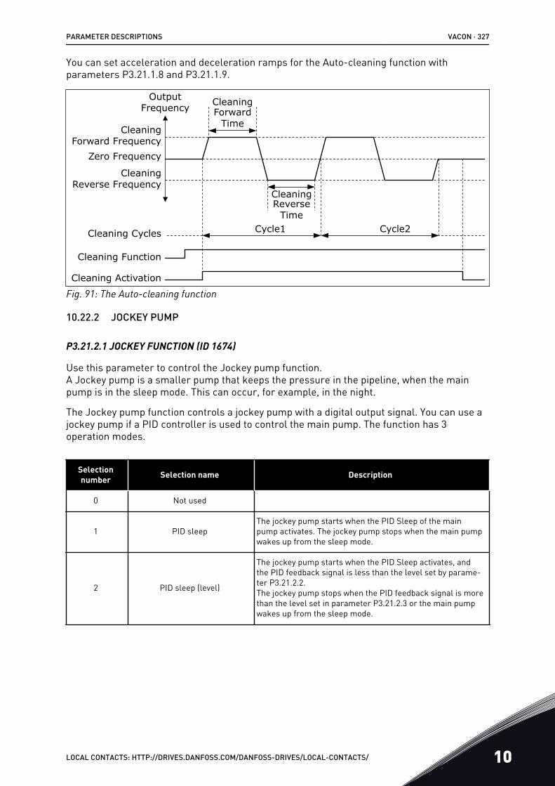
You can set acceleration and deceleration ramps for the Auto-cleaning function withparameters P3.21.1.8 and P3.21.1.9.
Zero Frequency
Output Frequency
Cleaning Forward Frequency
Cleaning Reverse Frequency
CleaningForward
Time
Cleaning Activation
CleaningReverse
Time
Cleaning Function
Cycle1 Cycle2Cleaning Cycles
Fig. 91: The Auto-cleaning function
10.22.2 JOCKEY PUMP
P3.21.2.1 JOCKEY FUNCTION (ID 1674)
Use this parameter to control the Jockey pump function.A Jockey pump is a smaller pump that keeps the pressure in the pipeline, when the mainpump is in the sleep mode. This can occur, for example, in the night.
The Jockey pump function controls a jockey pump with a digital output signal. You can use ajockey pump if a PID controller is used to control the main pump. The function has 3operation modes.
Selectionnumber Selection name Description
0 Not used
1 PID sleepThe jockey pump starts when the PID Sleep of the mainpump activates. The jockey pump stops when the main pumpwakes up from the sleep mode.
2 PID sleep (level)
The jockey pump starts when the PID Sleep activates, andthe PID feedback signal is less than the level set by parame-ter P3.21.2.2.The jockey pump stops when the PID feedback signal is morethan the level set in parameter P3.21.2.3 or the main pumpwakes up from the sleep mode.
PARAMETER DESCRIPTIONS VACON · 327
LOCAL CONTACTS: HTTP://DRIVES.DANFOSS.COM/DANFOSS-DRIVES/LOCAL-CONTACTS/ 10
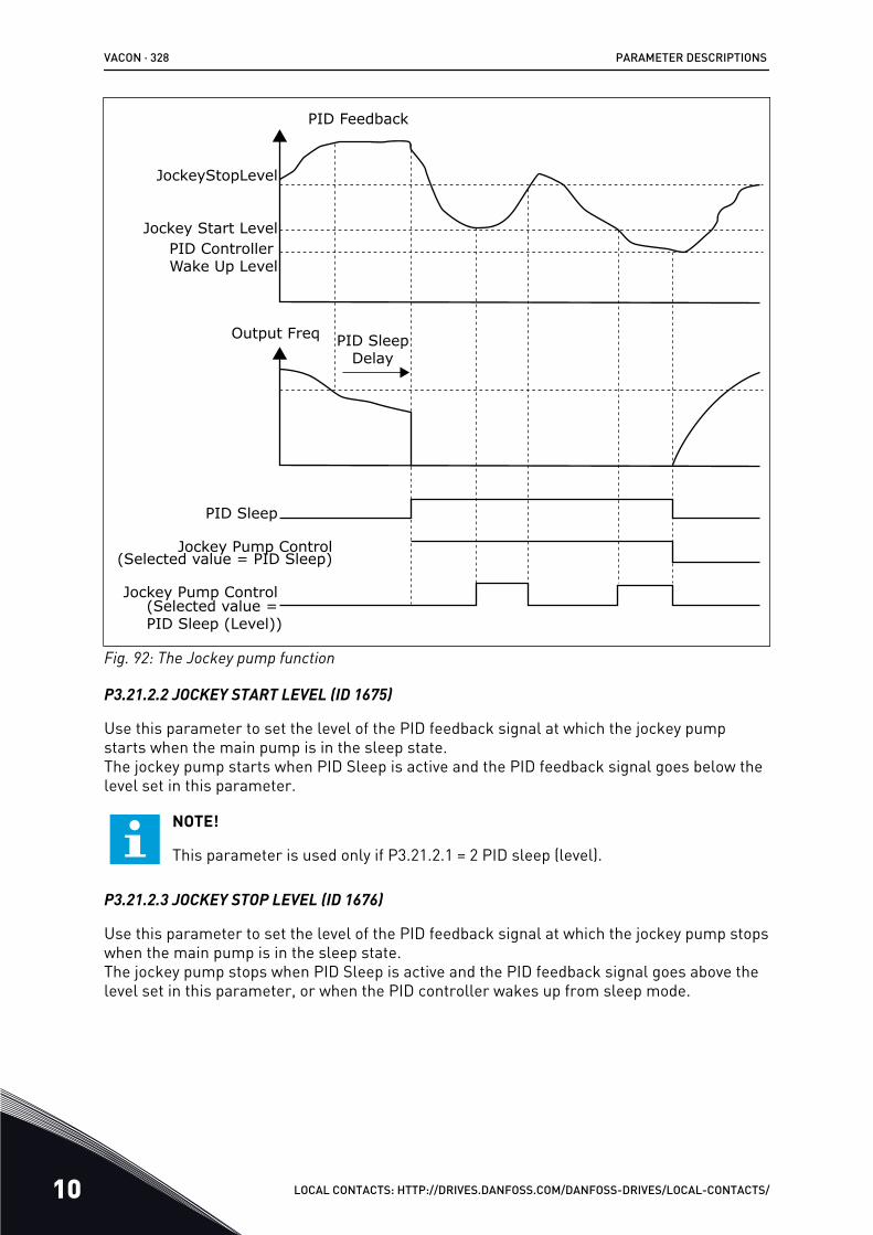
JockeyStopLevel
PID Feedback
Jockey Start LevelPID Controller Wake Up Level
Output Freq PID Sleep Delay
PID Sleep
Jockey Pump Control(Selected value = PID Sleep)
Jockey Pump Control(Selected value = PID Sleep (Level))
Fig. 92: The Jockey pump function
P3.21.2.2 JOCKEY START LEVEL (ID 1675)
Use this parameter to set the level of the PID feedback signal at which the jockey pumpstarts when the main pump is in the sleep state.The jockey pump starts when PID Sleep is active and the PID feedback signal goes below thelevel set in this parameter.
NOTE!
This parameter is used only if P3.21.2.1 = 2 PID sleep (level).
P3.21.2.3 JOCKEY STOP LEVEL (ID 1676)
Use this parameter to set the level of the PID feedback signal at which the jockey pump stopswhen the main pump is in the sleep state.The jockey pump stops when PID Sleep is active and the PID feedback signal goes above thelevel set in this parameter, or when the PID controller wakes up from sleep mode.
VACON · 328 PARAMETER DESCRIPTIONS
10 LOCAL CONTACTS: HTTP://DRIVES.DANFOSS.COM/DANFOSS-DRIVES/LOCAL-CONTACTS/
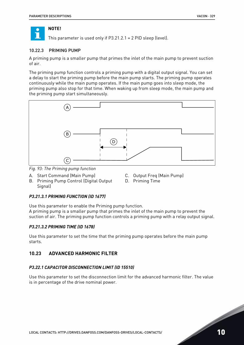
NOTE!
This parameter is used only if P3.21.2.1 = 2 PID sleep (level).
10.22.3 PRIMING PUMPA priming pump is a smaller pump that primes the inlet of the main pump to prevent suctionof air.
The priming pump function controls a priming pump with a digital output signal. You can seta delay to start the priming pump before the main pump starts. The priming pump operatescontinuously while the main pump operates. If the main pump goes into sleep mode, thepriming pump also stop for that time. When waking up from sleep mode, the main pump andthe priming pump start simultaneously.
A
B
C
D
Fig. 93: The Priming pump functionA. Start Command (Main Pump)B. Priming Pump Control (Digital Output
Signal)
C. Output Freq (Main Pump)D. Priming Time
P3.21.3.1 PRIMING FUNCTION (ID 1677)
Use this parameter to enable the Priming pump function.A priming pump is a smaller pump that primes the inlet of the main pump to prevent thesuction of air. The priming pump function controls a priming pump with a relay output signal.
P3.21.3.2 PRIMING TIME (ID 1678)
Use this parameter to set the time that the priming pump operates before the main pumpstarts.
10.23 ADVANCED HARMONIC FILTER
P3.22.1 CAPACITOR DISCONNECTION LIMIT (ID 15510)
Use this parameter to set the disconnection limit for the advanced harmonic filter. The valueis in percentage of the drive nominal power.
PARAMETER DESCRIPTIONS VACON · 329
LOCAL CONTACTS: HTTP://DRIVES.DANFOSS.COM/DANFOSS-DRIVES/LOCAL-CONTACTS/ 10

P3.22.2 CAPACITOR DISCONNECTION HYSTERESIS (ID 15511)
Use this parameter to set the disconnection hysteresis for the advanced harmonic filter. Thevalue is in percentage of the drive nominal power.
P3.22.3 AHF OVER TEMPERATURE (ID 15513)
Use this parameter to set the digital input signal that activates AHF Over Temp (fault ID1118).
P3.22.4 AHF FAULT RESPONSE (ID 15512)
Use this parameter to select the response of the AC drive to an AHF Over Temp fault.
VACON · 330 PARAMETER DESCRIPTIONS
10 LOCAL CONTACTS: HTTP://DRIVES.DANFOSS.COM/DANFOSS-DRIVES/LOCAL-CONTACTS/
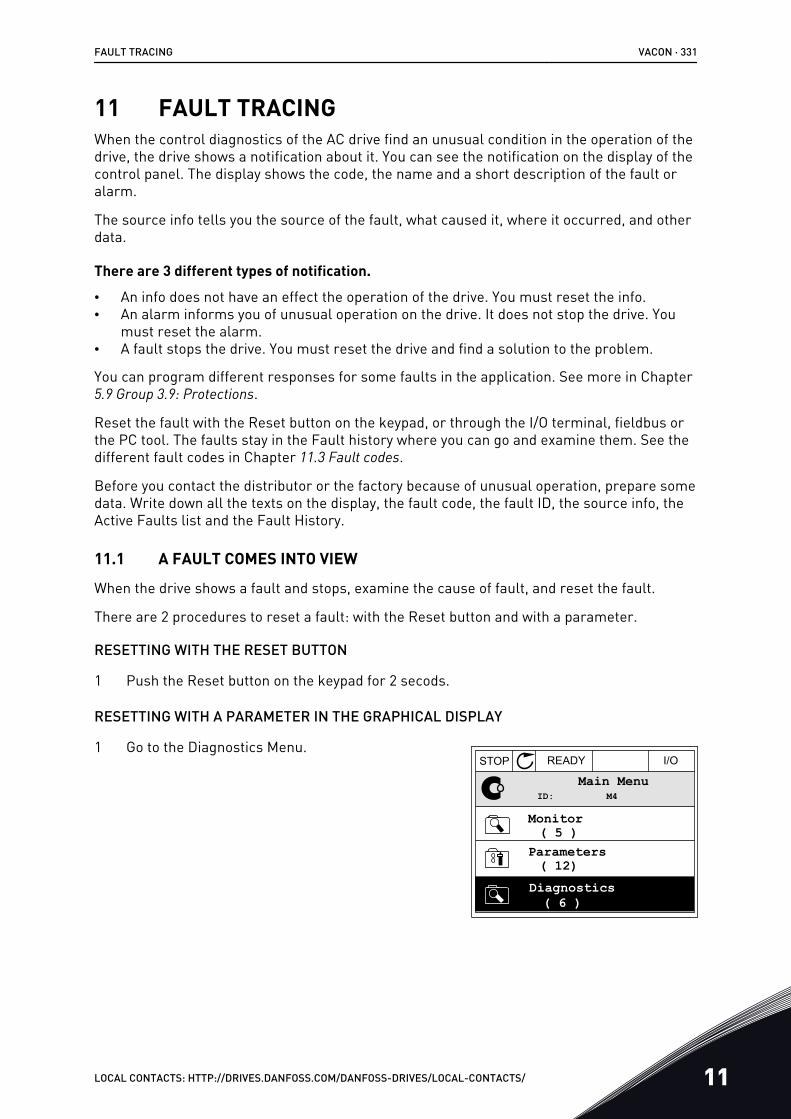
11 FAULT TRACINGWhen the control diagnostics of the AC drive find an unusual condition in the operation of thedrive, the drive shows a notification about it. You can see the notification on the display of thecontrol panel. The display shows the code, the name and a short description of the fault oralarm.
The source info tells you the source of the fault, what caused it, where it occurred, and otherdata.
There are 3 different types of notification.
• An info does not have an effect the operation of the drive. You must reset the info.• An alarm informs you of unusual operation on the drive. It does not stop the drive. You
must reset the alarm.• A fault stops the drive. You must reset the drive and find a solution to the problem.
You can program different responses for some faults in the application. See more in Chapter5.9 Group 3.9: Protections.
Reset the fault with the Reset button on the keypad, or through the I/O terminal, fieldbus orthe PC tool. The faults stay in the Fault history where you can go and examine them. See thedifferent fault codes in Chapter 11.3 Fault codes.
Before you contact the distributor or the factory because of unusual operation, prepare somedata. Write down all the texts on the display, the fault code, the fault ID, the source info, theActive Faults list and the Fault History.
11.1 A FAULT COMES INTO VIEW
When the drive shows a fault and stops, examine the cause of fault, and reset the fault.
There are 2 procedures to reset a fault: with the Reset button and with a parameter.
RESETTING WITH THE RESET BUTTON
1 Push the Reset button on the keypad for 2 secods.
RESETTING WITH A PARAMETER IN THE GRAPHICAL DISPLAY
1 Go to the Diagnostics Menu.STOP READY I/O
ID: M4Main Menu
( 12)
( 6 )
Parameters( 5 )
Monitor
Diagnostics
FAULT TRACING VACON · 331
LOCAL CONTACTS: HTTP://DRIVES.DANFOSS.COM/DANFOSS-DRIVES/LOCAL-CONTACTS/ 11
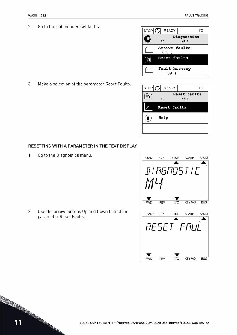
2 Go to the submenu Reset faults.STOP READY I/O
ID: M4.1Diagnostics
( 39 )
Reset faults( 0 )
Active faults
Fault history
3 Make a selection of the parameter Reset Faults.STOP READY I/O
ID: M4.2Reset faults
Help
Reset faults
RESETTING WITH A PARAMETER IN THE TEXT DISPLAY
1 Go to the Diagnostics menu.READY FAULTALARMSTOPRUN
KEYPADI/OREVFWD BUS
2 Use the arrow buttons Up and Down to find theparameter Reset Faults.
READY FAULTALARMSTOPRUN
KEYPADI/OREVFWD BUS
VACON · 332 FAULT TRACING
11 LOCAL CONTACTS: HTTP://DRIVES.DANFOSS.COM/DANFOSS-DRIVES/LOCAL-CONTACTS/
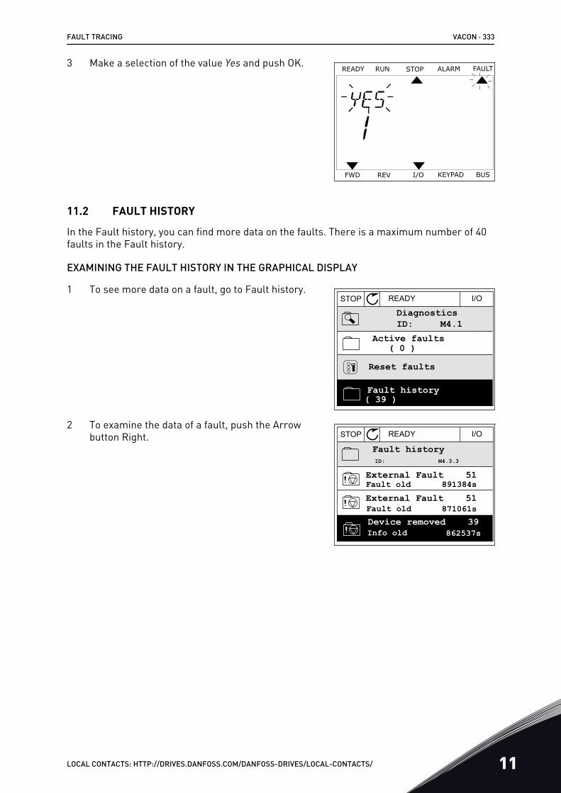
3 Make a selection of the value Yes and push OK.READY FAULTALARMSTOPRUN
KEYPADI/OREVFWD BUS
11.2 FAULT HISTORY
In the Fault history, you can find more data on the faults. There is a maximum number of 40faults in the Fault history.
EXAMINING THE FAULT HISTORY IN THE GRAPHICAL DISPLAY
1 To see more data on a fault, go to Fault history.
Active faults( 0 )
( 39 )
STOP READY I/O
DiagnosticsM4.1ID:
Reset faults
Fault history
2 To examine the data of a fault, push the Arrowbutton Right. STOP READY I/O
External Fault 51Fault old
Fault old
Info old 862537s
External Fault 51
Device removed 39
Fault historyM4.3.3ID:
891384s
871061s
FAULT TRACING VACON · 333
LOCAL CONTACTS: HTTP://DRIVES.DANFOSS.COM/DANFOSS-DRIVES/LOCAL-CONTACTS/ 11
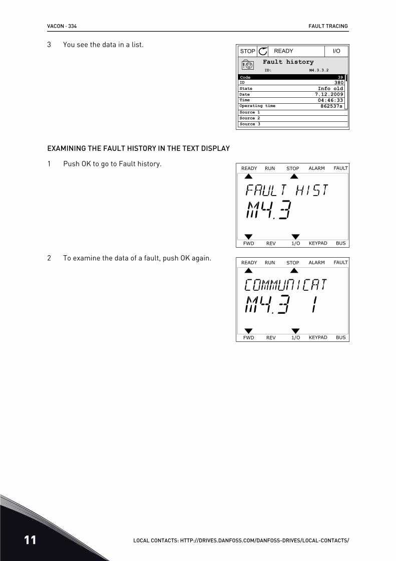
3 You see the data in a list.STOP READY I/O
Code 39
Source 3
Source 1
ID 380State Info oldDate 7.12.2009Time 04:46:33Operating time 862537s
Source 2
Fault historyM4.3.3.2ID:
EXAMINING THE FAULT HISTORY IN THE TEXT DISPLAY
1 Push OK to go to Fault history.READY FAULTALARMSTOPRUN
KEYPAD1/OREVFWD BUS
2 To examine the data of a fault, push OK again.READY FAULTALARMSTOPRUN
KEYPAD1/OREVFWD BUS
VACON · 334 FAULT TRACING
11 LOCAL CONTACTS: HTTP://DRIVES.DANFOSS.COM/DANFOSS-DRIVES/LOCAL-CONTACTS/
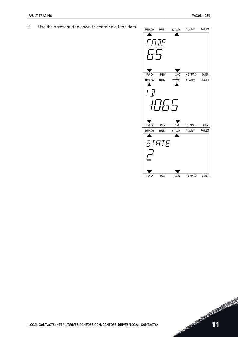
3 Use the arrow button down to examine all the data.READY FAULTALARMSTOPRUN
KEYPAD1/OREVFWD BUS
READY FAULTALARMSTOPRUN
KEYPAD1/OREVFWD BUS
READY FAULTALARMSTOPRUN
KEYPAD1/OREVFWD BUS
FAULT TRACING VACON · 335
LOCAL CONTACTS: HTTP://DRIVES.DANFOSS.COM/DANFOSS-DRIVES/LOCAL-CONTACTS/ 11
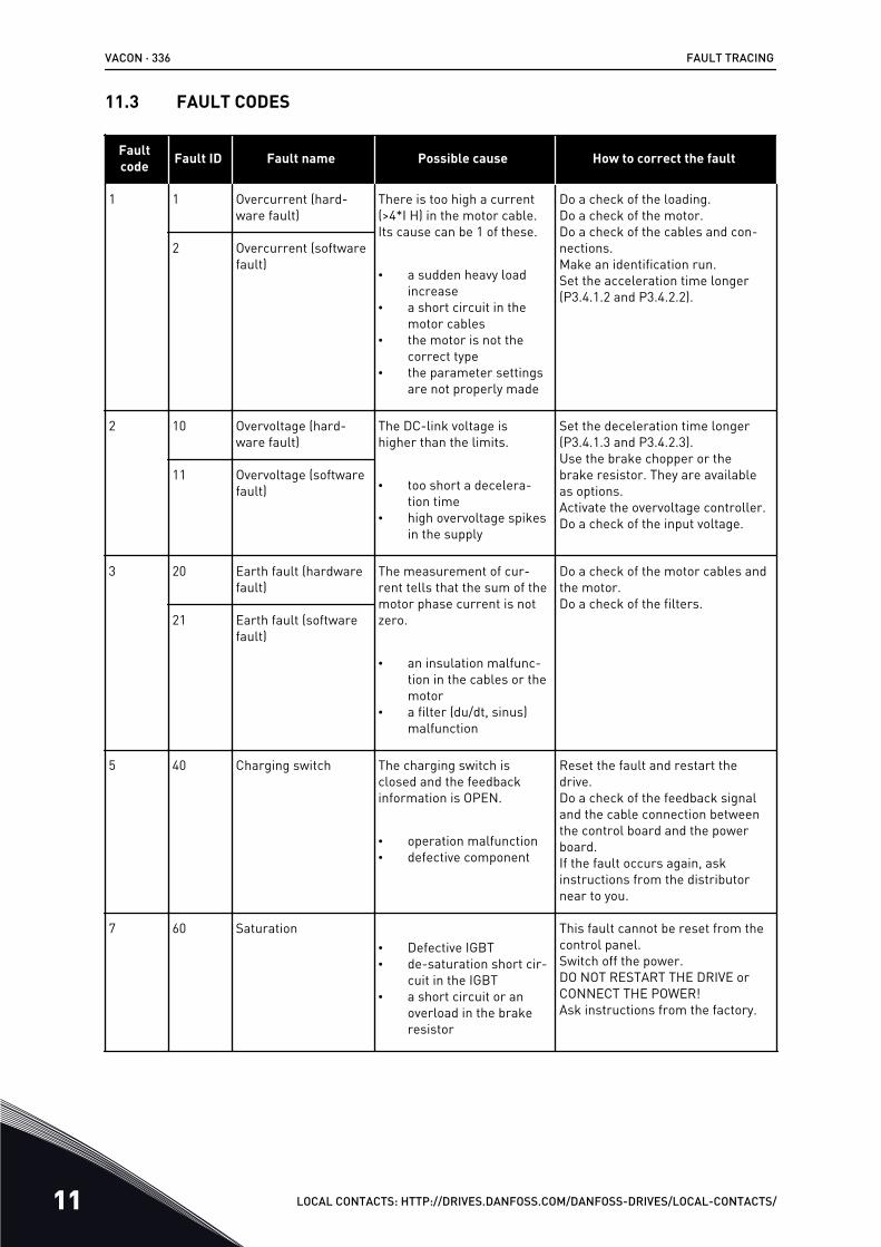
11.3 FAULT CODES
Faultcode Fault ID Fault name Possible cause How to correct the fault
1 1 Overcurrent (hard-ware fault)
There is too high a current(>4*I H) in the motor cable.Its cause can be 1 of these.
• a sudden heavy loadincrease
• a short circuit in themotor cables
• the motor is not thecorrect type
• the parameter settingsare not properly made
Do a check of the loading.Do a check of the motor.Do a check of the cables and con-nections.Make an identification run.Set the acceleration time longer(P3.4.1.2 and P3.4.2.2).
2 Overcurrent (softwarefault)
2 10 Overvoltage (hard-ware fault)
The DC-link voltage ishigher than the limits.
• too short a decelera-tion time
• high overvoltage spikesin the supply
Set the deceleration time longer(P3.4.1.3 and P3.4.2.3).Use the brake chopper or thebrake resistor. They are availableas options.Activate the overvoltage controller.Do a check of the input voltage.
11 Overvoltage (softwarefault)
3 20 Earth fault (hardwarefault)
The measurement of cur-rent tells that the sum of themotor phase current is notzero.
• an insulation malfunc-tion in the cables or themotor
• a filter (du/dt, sinus)malfunction
Do a check of the motor cables andthe motor.Do a check of the filters.
21 Earth fault (softwarefault)
5 40 Charging switch The charging switch isclosed and the feedbackinformation is OPEN.
• operation malfunction• defective component
Reset the fault and restart thedrive.Do a check of the feedback signaland the cable connection betweenthe control board and the powerboard.If the fault occurs again, askinstructions from the distributornear to you.
7 60 Saturation• Defective IGBT• de-saturation short cir-
cuit in the IGBT• a short circuit or an
overload in the brakeresistor
This fault cannot be reset from thecontrol panel.Switch off the power.DO NOT RESTART THE DRIVE orCONNECT THE POWER!Ask instructions from the factory.
VACON · 336 FAULT TRACING
11 LOCAL CONTACTS: HTTP://DRIVES.DANFOSS.COM/DANFOSS-DRIVES/LOCAL-CONTACTS/
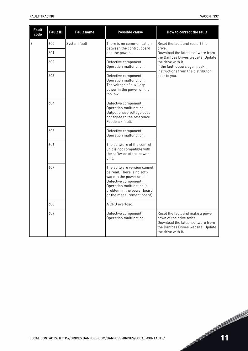
Faultcode Fault ID Fault name Possible cause How to correct the fault
8 600 System fault There is no communicationbetween the control boardand the power.
Reset the fault and restart thedrive.Download the latest software fromthe Danfoss Drives website. Updatethe drive with it.If the fault occurs again, askinstructions from the distributornear to you.
601
602 Defective component.Operation malfunction.
603 Defective component.Operation malfunction.The voltage of auxiliarypower in the power unit istoo low.
604 Defective component.Operation malfunction.Output phase voltage doesnot agree to the reference.Feedback fault.
605 Defective component.Operation malfunction.
606 The software of the controlunit is not compatible withthe software of the powerunit.
607 The software version cannotbe read. There is no soft-ware in the power unit.Defective component.Operation malfunction (aproblem in the power boardor the measurement board).
608 A CPU overload.
609 Defective component.Operation malfunction.
Reset the fault and make a powerdown of the drive twice.Download the latest software fromthe Danfoss Drives website. Updatethe drive with it.
FAULT TRACING VACON · 337
LOCAL CONTACTS: HTTP://DRIVES.DANFOSS.COM/DANFOSS-DRIVES/LOCAL-CONTACTS/ 11
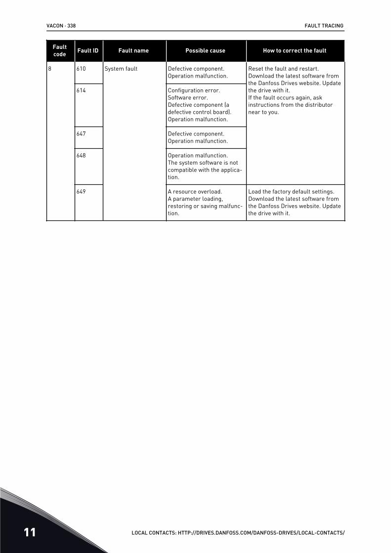
Faultcode Fault ID Fault name Possible cause How to correct the fault
8 610 System fault Defective component.Operation malfunction.
Reset the fault and restart.Download the latest software fromthe Danfoss Drives website. Updatethe drive with it.If the fault occurs again, askinstructions from the distributornear to you.
614 Configuration error.Software error.Defective component (adefective control board).Operation malfunction.
647 Defective component.Operation malfunction.
648 Operation malfunction.The system software is notcompatible with the applica-tion.
649 A resource overload.A parameter loading,restoring or saving malfunc-tion.
Load the factory default settings.Download the latest software fromthe Danfoss Drives website. Updatethe drive with it.
VACON · 338 FAULT TRACING
11 LOCAL CONTACTS: HTTP://DRIVES.DANFOSS.COM/DANFOSS-DRIVES/LOCAL-CONTACTS/
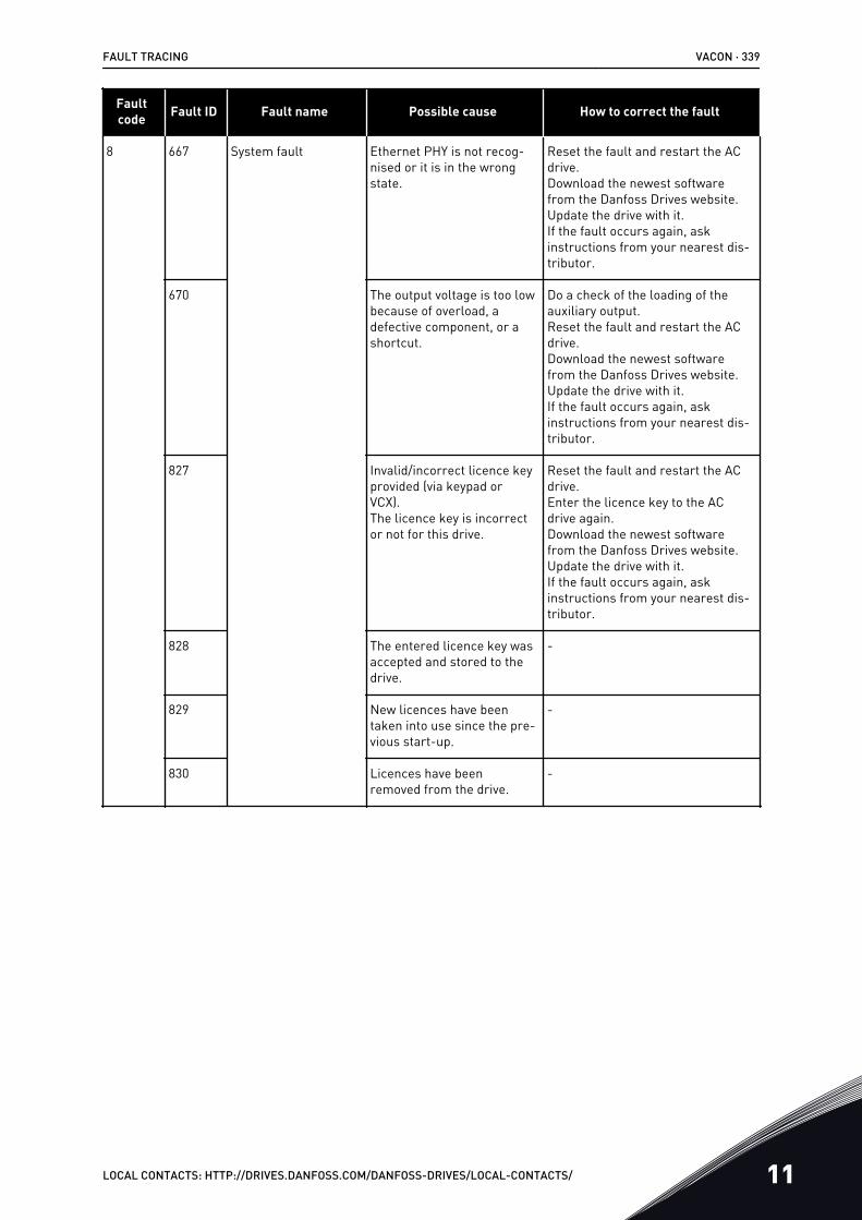
Faultcode Fault ID Fault name Possible cause How to correct the fault
8 667 System fault Ethernet PHY is not recog-nised or it is in the wrongstate.
Reset the fault and restart the ACdrive.Download the newest softwarefrom the Danfoss Drives website.Update the drive with it.If the fault occurs again, askinstructions from your nearest dis-tributor.
670 The output voltage is too lowbecause of overload, adefective component, or ashortcut.
Do a check of the loading of theauxiliary output.Reset the fault and restart the ACdrive.Download the newest softwarefrom the Danfoss Drives website.Update the drive with it.If the fault occurs again, askinstructions from your nearest dis-tributor.
827 Invalid/incorrect licence keyprovided (via keypad orVCX).The licence key is incorrector not for this drive.
Reset the fault and restart the ACdrive.Enter the licence key to the ACdrive again.Download the newest softwarefrom the Danfoss Drives website.Update the drive with it.If the fault occurs again, askinstructions from your nearest dis-tributor.
828 The entered licence key wasaccepted and stored to thedrive.
-
829 New licences have beentaken into use since the pre-vious start-up.
-
830 Licences have beenremoved from the drive.
-
FAULT TRACING VACON · 339
LOCAL CONTACTS: HTTP://DRIVES.DANFOSS.COM/DANFOSS-DRIVES/LOCAL-CONTACTS/ 11
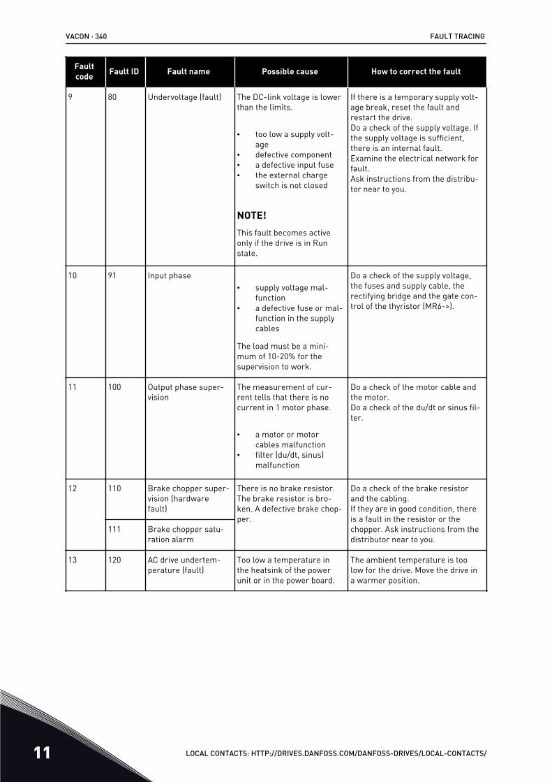
Faultcode Fault ID Fault name Possible cause How to correct the fault
9 80 Undervoltage (fault) The DC-link voltage is lowerthan the limits.
• too low a supply volt-age
• defective component• a defective input fuse• the external charge
switch is not closed
NOTE!This fault becomes activeonly if the drive is in Runstate.
If there is a temporary supply volt-age break, reset the fault andrestart the drive.Do a check of the supply voltage. Ifthe supply voltage is sufficient,there is an internal fault.Examine the electrical network forfault.Ask instructions from the distribu-tor near to you.
10 91 Input phase• supply voltage mal-
function• a defective fuse or mal-
function in the supplycables
The load must be a mini-mum of 10-20% for thesupervision to work.
Do a check of the supply voltage,the fuses and supply cable, therectifying bridge and the gate con-trol of the thyristor (MR6->).
11 100 Output phase super-vision
The measurement of cur-rent tells that there is nocurrent in 1 motor phase.
• a motor or motorcables malfunction
• filter (du/dt, sinus)malfunction
Do a check of the motor cable andthe motor.Do a check of the du/dt or sinus fil-ter.
12 110 Brake chopper super-vision (hardwarefault)
There is no brake resistor.The brake resistor is bro-ken. A defective brake chop-per.
Do a check of the brake resistorand the cabling.If they are in good condition, thereis a fault in the resistor or thechopper. Ask instructions from thedistributor near to you.
111 Brake chopper satu-ration alarm
13 120 AC drive undertem-perature (fault)
Too low a temperature inthe heatsink of the powerunit or in the power board.
The ambient temperature is toolow for the drive. Move the drive ina warmer position.
VACON · 340 FAULT TRACING
11 LOCAL CONTACTS: HTTP://DRIVES.DANFOSS.COM/DANFOSS-DRIVES/LOCAL-CONTACTS/
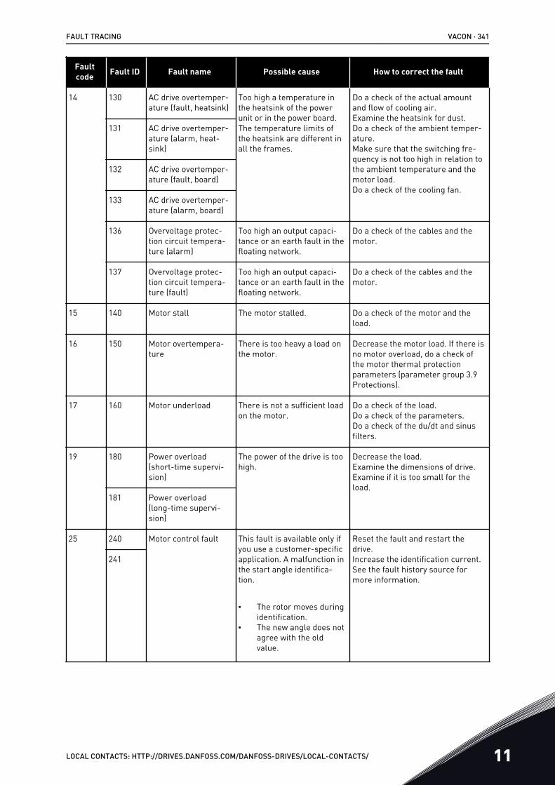
Faultcode Fault ID Fault name Possible cause How to correct the fault
14 130 AC drive overtemper-ature (fault, heatsink)
Too high a temperature inthe heatsink of the powerunit or in the power board.The temperature limits ofthe heatsink are different inall the frames.
Do a check of the actual amountand flow of cooling air.Examine the heatsink for dust.Do a check of the ambient temper-ature.Make sure that the switching fre-quency is not too high in relation tothe ambient temperature and themotor load.Do a check of the cooling fan.
131 AC drive overtemper-ature (alarm, heat-sink)
132 AC drive overtemper-ature (fault, board)
133 AC drive overtemper-ature (alarm, board)
136 Overvoltage protec-tion circuit tempera-ture (alarm)
Too high an output capaci-tance or an earth fault in thefloating network.
Do a check of the cables and themotor.
137 Overvoltage protec-tion circuit tempera-ture (fault)
Too high an output capaci-tance or an earth fault in thefloating network.
Do a check of the cables and themotor.
15 140 Motor stall The motor stalled. Do a check of the motor and theload.
16 150 Motor overtempera-ture
There is too heavy a load onthe motor.
Decrease the motor load. If there isno motor overload, do a check ofthe motor thermal protectionparameters (parameter group 3.9Protections).
17 160 Motor underload There is not a sufficient loadon the motor.
Do a check of the load.Do a check of the parameters.Do a check of the du/dt and sinusfilters.
19 180 Power overload(short-time supervi-sion)
The power of the drive is toohigh.
Decrease the load.Examine the dimensions of drive.Examine if it is too small for theload.
181 Power overload(long-time supervi-sion)
25 240 Motor control fault This fault is available only ifyou use a customer-specificapplication. A malfunction inthe start angle identifica-tion.
• The rotor moves duringidentification.
• The new angle does notagree with the oldvalue.
Reset the fault and restart thedrive.Increase the identification current.See the fault history source formore information.
241
FAULT TRACING VACON · 341
LOCAL CONTACTS: HTTP://DRIVES.DANFOSS.COM/DANFOSS-DRIVES/LOCAL-CONTACTS/ 11
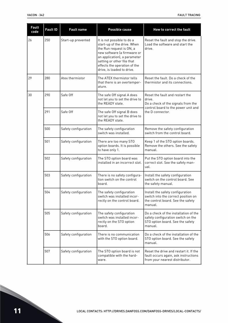
Faultcode Fault ID Fault name Possible cause How to correct the fault
26 250 Start-up prevented It is not possible to do astart-up of the drive. Whenthe Run request is ON, anew software (a firmware oran application), a parametersetting or other file thateffects the operation of thedrive, is loaded to drive.
Reset the fault and stop the drive.Load the software and start thedrive.
29 280 Atex thermistor The ATEX thermistor tellsthat there is an overtemper-ature.
Reset the fault. Do a check of thethermistor and its connections.
30 290 Safe Off The safe Off signal A doesnot let you to set the drive tothe READY state.
Reset the fault and restart thedrive.Do a check of the signals from thecontrol board to the power unit andthe D connector.291 Safe Off The safe Off signal B does
not let you to set the drive tothe READY state.
500 Safety configuration The safety configurationswitch was installed.
Remove the safety configurationswitch from the control board.
501 Safety configuration There are too many STOoption boards. It is possibleto have only 1.
Keep 1 of the STO option boards.Remove the others. See the safetymanual.
502 Safety configuration The STO option board wasinstalled in an incorrect slot.
Put the STO option board into thecorrect slot. See the safety man-ual.
503 Safety configuration There is no safety configura-tion switch on the controlboard.
Install the safety configurationswitch on the control board. Seethe safety manual.
504 Safety configuration The safety configurationswitch was installed incor-rectly on the control board.
Install the safety configurationswitch into the correct position onthe control board. See the safetymanual.
505 Safety configuration The safety configurationswitch was installed incor-rectly on the STO optionboard.
Do a check of the installation of thesafety configuration switch on theSTO option board. See the safetymanual.
506 Safety configuration There is no communicationwith the STO option board.
Do a check of the installation of theSTO option board. See the safetymanual.
507 Safety configuration The STO option board is notcompatible with the hard-ware.
Reset the drive and restart it. If thefault occurs again, ask instructionsfrom your nearest distributor.
VACON · 342 FAULT TRACING
11 LOCAL CONTACTS: HTTP://DRIVES.DANFOSS.COM/DANFOSS-DRIVES/LOCAL-CONTACTS/
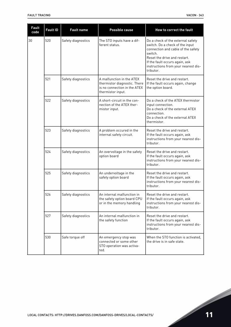
Faultcode Fault ID Fault name Possible cause How to correct the fault
30 520 Safety diagnostics The STO inputs have a dif-ferent status.
Do a check of the external safetyswitch. Do a check of the inputconnection and cable of the safetyswitch.Reset the drive and restart.If the fault occurs again, askinstructions from your nearest dis-tributor.
521 Safety diagnostics A malfunction in the ATEXthermistor diagnostic. Thereis no connection in the ATEXthermistor input.
Reset the drive and restart.If the fault occurs again, changethe option board.
522 Safety diagnostics A short-circuit in the con-nection of the ATEX ther-mistor input.
Do a check of the ATEX thermistorinput connection.Do a check of the external ATEXconnection.Do a check of the external ATEXthermistor.
523 Safety diagnostics A problem occured in theinternal safety circuit.
Reset the drive and restart.If the fault occurs again, askinstructions from your nearest dis-tributor.
524 Safety diagnostics An overvoltage in the safetyoption board
Reset the drive and restart.If the fault occurs again, askinstructions from your nearest dis-tributor.
525 Safety diagnostics An undervoltage in thesafety option board
Reset the drive and restart.If the fault occurs again, askinstructions from your nearest dis-tributor.
526 Safety diagnostics An internal malfunction inthe safety option board CPUor in the memory handling
Reset the drive and restart.If the fault occurs again, askinstructions from your nearest dis-tributor.
527 Safety diagnostics An internal malfunction inthe safety function
Reset the drive and restart.If the fault occurs again, askinstructions from your nearest dis-tributor.
530 Safe torque off An emergency stop wasconnected or some otherSTO operation was activa-ted.
When the STO function is activated,the drive is in safe state.
FAULT TRACING VACON · 343
LOCAL CONTACTS: HTTP://DRIVES.DANFOSS.COM/DANFOSS-DRIVES/LOCAL-CONTACTS/ 11
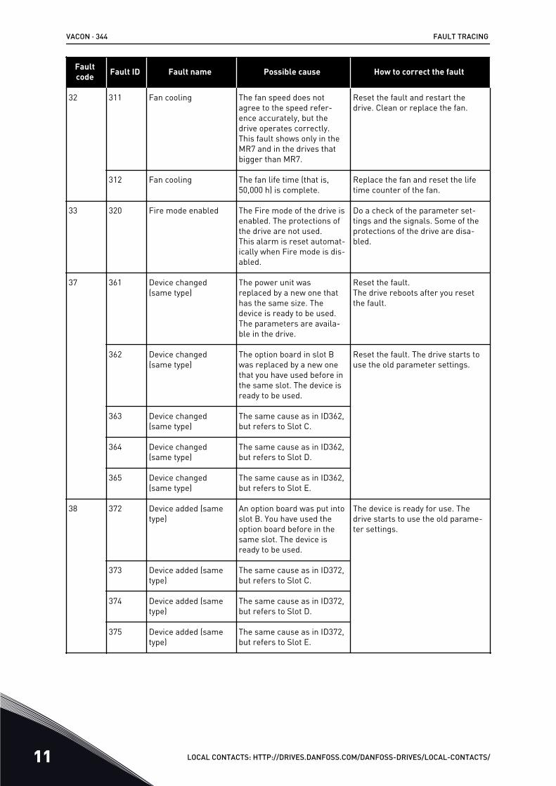
Faultcode Fault ID Fault name Possible cause How to correct the fault
32 311 Fan cooling The fan speed does notagree to the speed refer-ence accurately, but thedrive operates correctly.This fault shows only in theMR7 and in the drives thatbigger than MR7.
Reset the fault and restart thedrive. Clean or replace the fan.
312 Fan cooling The fan life time (that is,50,000 h) is complete.
Replace the fan and reset the lifetime counter of the fan.
33 320 Fire mode enabled The Fire mode of the drive isenabled. The protections ofthe drive are not used.This alarm is reset automat-ically when Fire mode is dis-abled.
Do a check of the parameter set-tings and the signals. Some of theprotections of the drive are disa-bled.
37 361 Device changed(same type)
The power unit wasreplaced by a new one thathas the same size. Thedevice is ready to be used.The parameters are availa-ble in the drive.
Reset the fault.The drive reboots after you resetthe fault.
362 Device changed(same type)
The option board in slot Bwas replaced by a new onethat you have used before inthe same slot. The device isready to be used.
Reset the fault. The drive starts touse the old parameter settings.
363 Device changed(same type)
The same cause as in ID362,but refers to Slot C.
364 Device changed(same type)
The same cause as in ID362,but refers to Slot D.
365 Device changed(same type)
The same cause as in ID362,but refers to Slot E.
38 372 Device added (sametype)
An option board was put intoslot B. You have used theoption board before in thesame slot. The device isready to be used.
The device is ready for use. Thedrive starts to use the old parame-ter settings.
373 Device added (sametype)
The same cause as in ID372,but refers to Slot C.
374 Device added (sametype)
The same cause as in ID372,but refers to Slot D.
375 Device added (sametype)
The same cause as in ID372,but refers to Slot E.
VACON · 344 FAULT TRACING
11 LOCAL CONTACTS: HTTP://DRIVES.DANFOSS.COM/DANFOSS-DRIVES/LOCAL-CONTACTS/
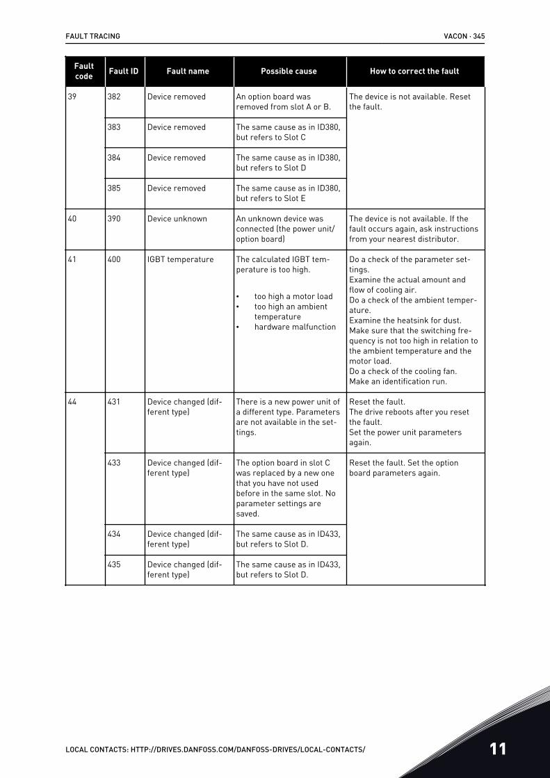
Faultcode Fault ID Fault name Possible cause How to correct the fault
39 382 Device removed An option board wasremoved from slot A or B.
The device is not available. Resetthe fault.
383 Device removed The same cause as in ID380,but refers to Slot C
384 Device removed The same cause as in ID380,but refers to Slot D
385 Device removed The same cause as in ID380,but refers to Slot E
40 390 Device unknown An unknown device wasconnected (the power unit/option board)
The device is not available. If thefault occurs again, ask instructionsfrom your nearest distributor.
41 400 IGBT temperature The calculated IGBT tem-perature is too high.
• too high a motor load• too high an ambient
temperature• hardware malfunction
Do a check of the parameter set-tings.Examine the actual amount andflow of cooling air.Do a check of the ambient temper-ature.Examine the heatsink for dust.Make sure that the switching fre-quency is not too high in relation tothe ambient temperature and themotor load.Do a check of the cooling fan.Make an identification run.
44 431 Device changed (dif-ferent type)
There is a new power unit ofa different type. Parametersare not available in the set-tings.
Reset the fault.The drive reboots after you resetthe fault.Set the power unit parametersagain.
433 Device changed (dif-ferent type)
The option board in slot Cwas replaced by a new onethat you have not usedbefore in the same slot. Noparameter settings aresaved.
Reset the fault. Set the optionboard parameters again.
434 Device changed (dif-ferent type)
The same cause as in ID433,but refers to Slot D.
435 Device changed (dif-ferent type)
The same cause as in ID433,but refers to Slot D.
FAULT TRACING VACON · 345
LOCAL CONTACTS: HTTP://DRIVES.DANFOSS.COM/DANFOSS-DRIVES/LOCAL-CONTACTS/ 11
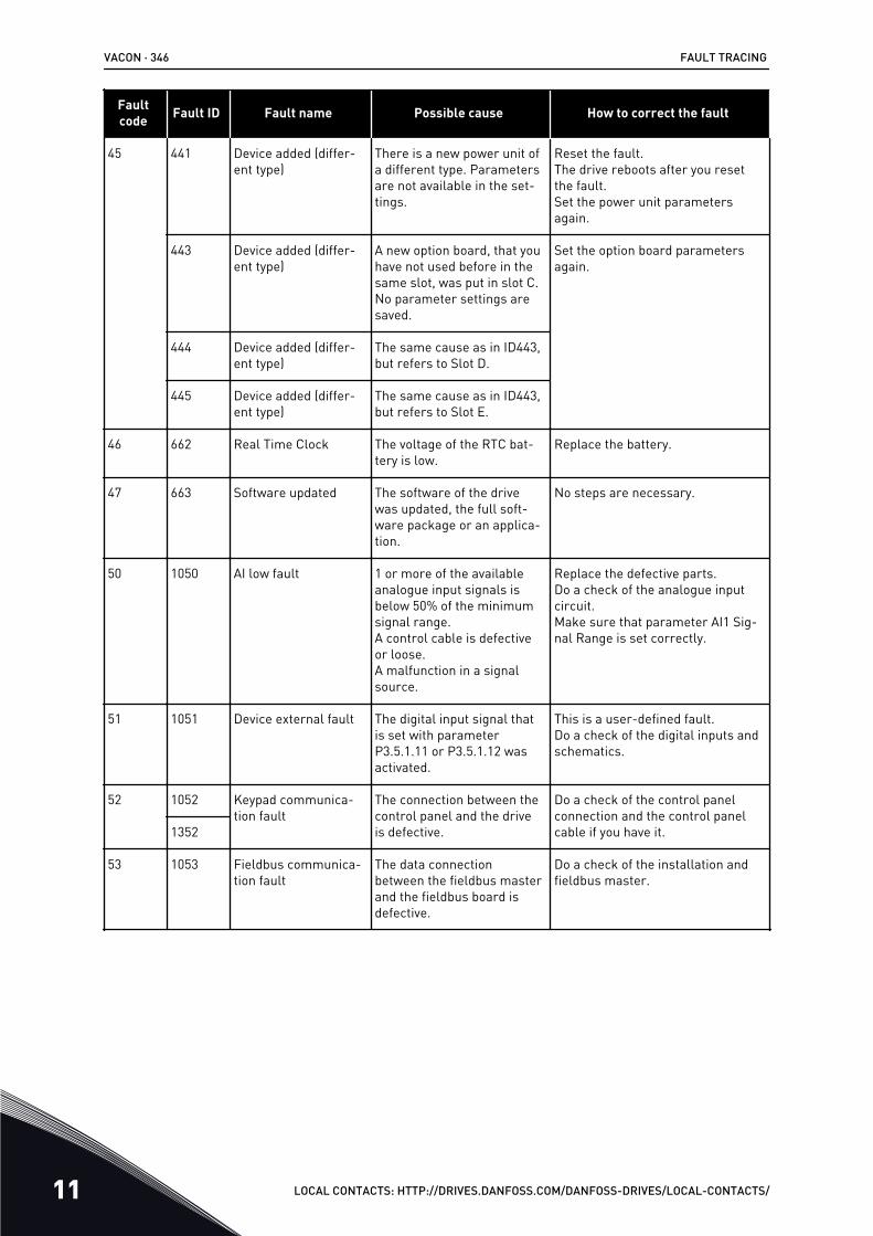
Faultcode Fault ID Fault name Possible cause How to correct the fault
45 441 Device added (differ-ent type)
There is a new power unit ofa different type. Parametersare not available in the set-tings.
Reset the fault.The drive reboots after you resetthe fault.Set the power unit parametersagain.
443 Device added (differ-ent type)
A new option board, that youhave not used before in thesame slot, was put in slot C.No parameter settings aresaved.
Set the option board parametersagain.
444 Device added (differ-ent type)
The same cause as in ID443,but refers to Slot D.
445 Device added (differ-ent type)
The same cause as in ID443,but refers to Slot E.
46 662 Real Time Clock The voltage of the RTC bat-tery is low.
Replace the battery.
47 663 Software updated The software of the drivewas updated, the full soft-ware package or an applica-tion.
No steps are necessary.
50 1050 AI low fault 1 or more of the availableanalogue input signals isbelow 50% of the minimumsignal range.A control cable is defectiveor loose.A malfunction in a signalsource.
Replace the defective parts.Do a check of the analogue inputcircuit.Make sure that parameter AI1 Sig-nal Range is set correctly.
51 1051 Device external fault The digital input signal thatis set with parameterP3.5.1.11 or P3.5.1.12 wasactivated.
This is a user-defined fault.Do a check of the digital inputs andschematics.
52 1052 Keypad communica-tion fault
The connection between thecontrol panel and the driveis defective.
Do a check of the control panelconnection and the control panelcable if you have it.1352
53 1053 Fieldbus communica-tion fault
The data connectionbetween the fieldbus masterand the fieldbus board isdefective.
Do a check of the installation andfieldbus master.
VACON · 346 FAULT TRACING
11 LOCAL CONTACTS: HTTP://DRIVES.DANFOSS.COM/DANFOSS-DRIVES/LOCAL-CONTACTS/
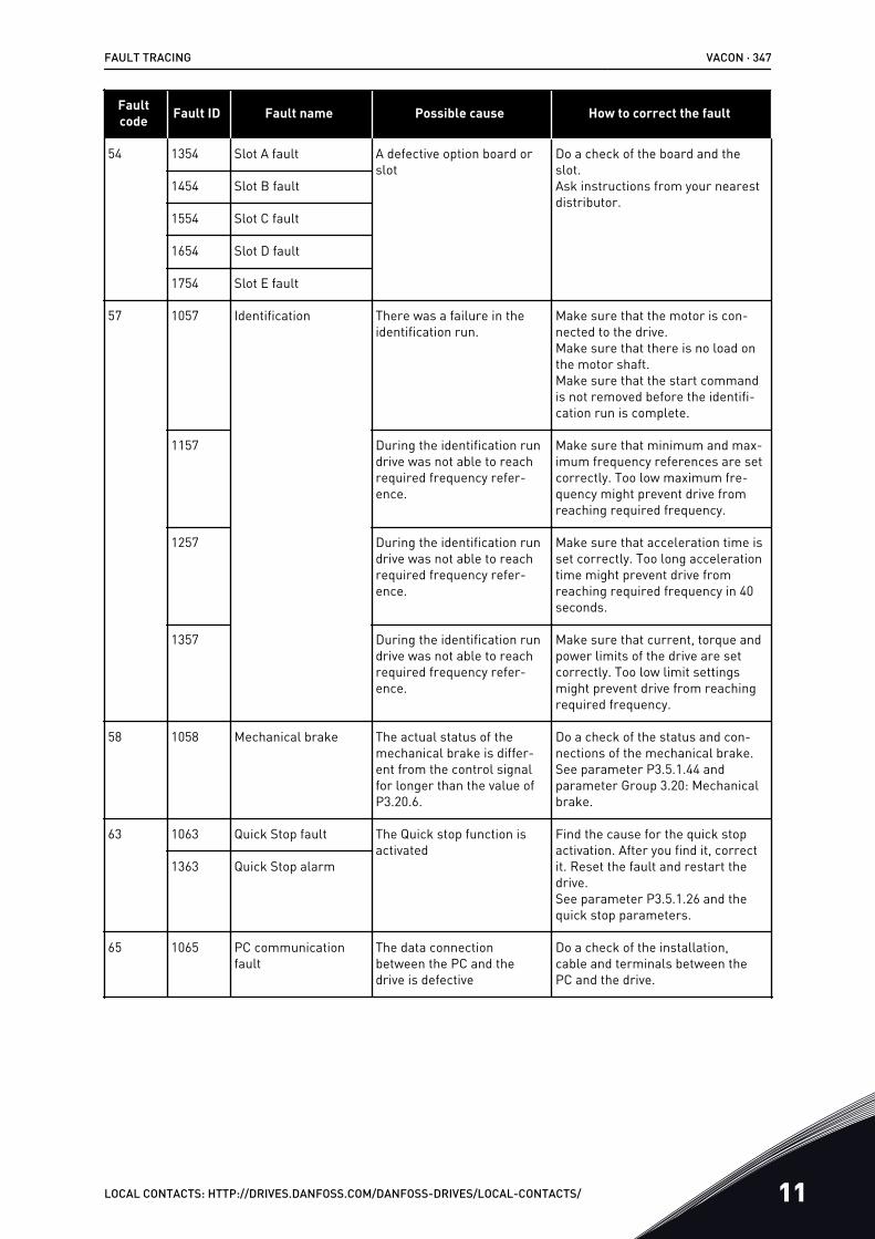
Faultcode Fault ID Fault name Possible cause How to correct the fault
54 1354 Slot A fault A defective option board orslot
Do a check of the board and theslot.Ask instructions from your nearestdistributor.
1454 Slot B fault
1554 Slot C fault
1654 Slot D fault
1754 Slot E fault
57 1057 Identification There was a failure in theidentification run.
Make sure that the motor is con-nected to the drive.Make sure that there is no load onthe motor shaft.Make sure that the start commandis not removed before the identifi-cation run is complete.
1157 During the identification rundrive was not able to reachrequired frequency refer-ence.
Make sure that minimum and max-imum frequency references are setcorrectly. Too low maximum fre-quency might prevent drive fromreaching required frequency.
1257 During the identification rundrive was not able to reachrequired frequency refer-ence.
Make sure that acceleration time isset correctly. Too long accelerationtime might prevent drive fromreaching required frequency in 40seconds.
1357 During the identification rundrive was not able to reachrequired frequency refer-ence.
Make sure that current, torque andpower limits of the drive are setcorrectly. Too low limit settingsmight prevent drive from reachingrequired frequency.
58 1058 Mechanical brake The actual status of themechanical brake is differ-ent from the control signalfor longer than the value ofP3.20.6.
Do a check of the status and con-nections of the mechanical brake.See parameter P3.5.1.44 andparameter Group 3.20: Mechanicalbrake.
63 1063 Quick Stop fault The Quick stop function isactivated
Find the cause for the quick stopactivation. After you find it, correctit. Reset the fault and restart thedrive.See parameter P3.5.1.26 and thequick stop parameters.
1363 Quick Stop alarm
65 1065 PC communicationfault
The data connectionbetween the PC and thedrive is defective
Do a check of the installation,cable and terminals between thePC and the drive.
FAULT TRACING VACON · 347
LOCAL CONTACTS: HTTP://DRIVES.DANFOSS.COM/DANFOSS-DRIVES/LOCAL-CONTACTS/ 11
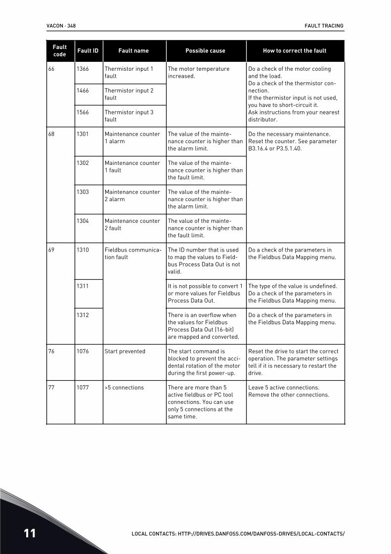
Faultcode Fault ID Fault name Possible cause How to correct the fault
66 1366 Thermistor input 1fault
The motor temperatureincreased.
Do a check of the motor coolingand the load.Do a check of the thermistor con-nection.If the thermistor input is not used,you have to short-circuit it.Ask instructions from your nearestdistributor.
1466 Thermistor input 2fault
1566 Thermistor input 3fault
68 1301 Maintenance counter1 alarm
The value of the mainte-nance counter is higher thanthe alarm limit.
Do the necessary maintenance.Reset the counter. See parameterB3.16.4 or P3.5.1.40.
1302 Maintenance counter1 fault
The value of the mainte-nance counter is higher thanthe fault limit.
1303 Maintenance counter2 alarm
The value of the mainte-nance counter is higher thanthe alarm limit.
1304 Maintenance counter2 fault
The value of the mainte-nance counter is higher thanthe fault limit.
69 1310 Fieldbus communica-tion fault
The ID number that is usedto map the values to Field-bus Process Data Out is notvalid.
Do a check of the parameters inthe Fieldbus Data Mapping menu.
1311 It is not possible to convert 1or more values for FieldbusProcess Data Out.
The type of the value is undefined.Do a check of the parameters inthe Fieldbus Data Mapping menu.
1312 There is an overflow whenthe values for FieldbusProcess Data Out (16-bit)are mapped and converted.
Do a check of the parameters inthe Fieldbus Data Mapping menu.
76 1076 Start prevented The start command isblocked to prevent the acci-dental rotation of the motorduring the first power-up.
Reset the drive to start the correctoperation. The parameter settingstell if it is necessary to restart thedrive.
77 1077 >5 connections There are more than 5active fieldbus or PC toolconnections. You can useonly 5 connections at thesame time.
Leave 5 active connections.Remove the other connections.
VACON · 348 FAULT TRACING
11 LOCAL CONTACTS: HTTP://DRIVES.DANFOSS.COM/DANFOSS-DRIVES/LOCAL-CONTACTS/
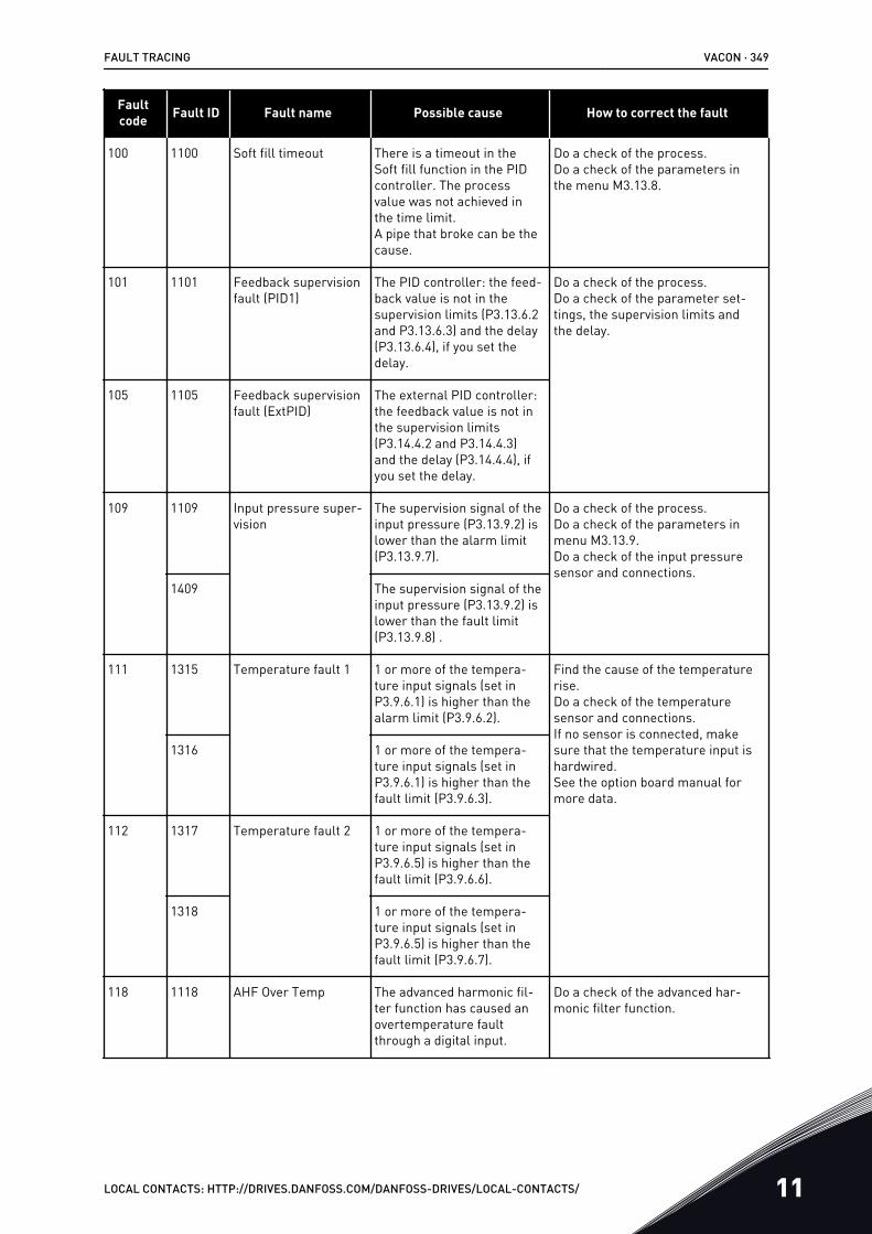
Faultcode Fault ID Fault name Possible cause How to correct the fault
100 1100 Soft fill timeout There is a timeout in theSoft fill function in the PIDcontroller. The processvalue was not achieved inthe time limit.A pipe that broke can be thecause.
Do a check of the process.Do a check of the parameters inthe menu M3.13.8.
101 1101 Feedback supervisionfault (PID1)
The PID controller: the feed-back value is not in thesupervision limits (P3.13.6.2and P3.13.6.3) and the delay(P3.13.6.4), if you set thedelay.
Do a check of the process.Do a check of the parameter set-tings, the supervision limits andthe delay.
105 1105 Feedback supervisionfault (ExtPID)
The external PID controller:the feedback value is not inthe supervision limits(P3.14.4.2 and P3.14.4.3)and the delay (P3.14.4.4), ifyou set the delay.
109 1109 Input pressure super-vision
The supervision signal of theinput pressure (P3.13.9.2) islower than the alarm limit(P3.13.9.7).
Do a check of the process.Do a check of the parameters inmenu M3.13.9.Do a check of the input pressuresensor and connections.
1409 The supervision signal of theinput pressure (P3.13.9.2) islower than the fault limit(P3.13.9.8) .
111 1315 Temperature fault 1 1 or more of the tempera-ture input signals (set inP3.9.6.1) is higher than thealarm limit (P3.9.6.2).
Find the cause of the temperaturerise.Do a check of the temperaturesensor and connections.If no sensor is connected, makesure that the temperature input ishardwired.See the option board manual formore data.
1316 1 or more of the tempera-ture input signals (set inP3.9.6.1) is higher than thefault limit (P3.9.6.3).
112 1317 Temperature fault 2 1 or more of the tempera-ture input signals (set inP3.9.6.5) is higher than thefault limit (P3.9.6.6).
1318 1 or more of the tempera-ture input signals (set inP3.9.6.5) is higher than thefault limit (P3.9.6.7).
118 1118 AHF Over Temp The advanced harmonic fil-ter function has caused anovertemperature faultthrough a digital input.
Do a check of the advanced har-monic filter function.
FAULT TRACING VACON · 349
LOCAL CONTACTS: HTTP://DRIVES.DANFOSS.COM/DANFOSS-DRIVES/LOCAL-CONTACTS/ 11
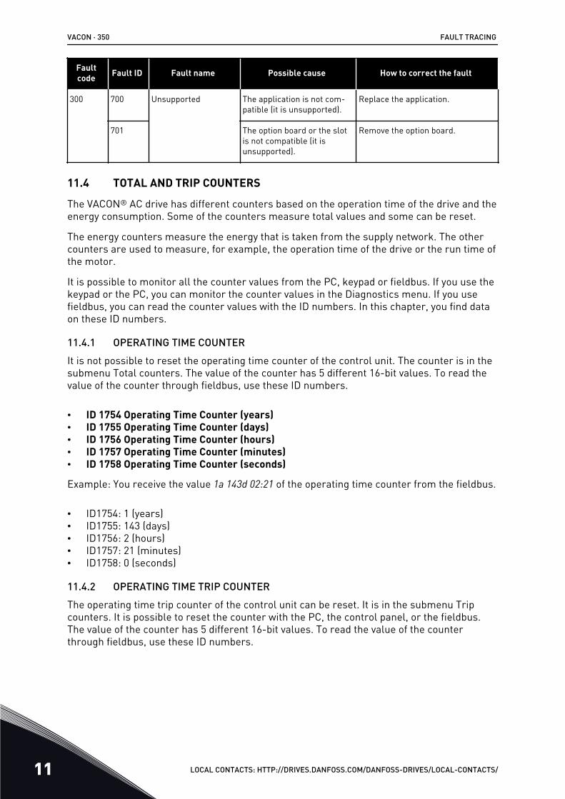
Faultcode Fault ID Fault name Possible cause How to correct the fault
300 700 Unsupported The application is not com-patible (it is unsupported).
Replace the application.
701 The option board or the slotis not compatible (it isunsupported).
Remove the option board.
11.4 TOTAL AND TRIP COUNTERS
The VACON® AC drive has different counters based on the operation time of the drive and theenergy consumption. Some of the counters measure total values and some can be reset.
The energy counters measure the energy that is taken from the supply network. The othercounters are used to measure, for example, the operation time of the drive or the run time ofthe motor.
It is possible to monitor all the counter values from the PC, keypad or fieldbus. If you use thekeypad or the PC, you can monitor the counter values in the Diagnostics menu. If you usefieldbus, you can read the counter values with the ID numbers. In this chapter, you find dataon these ID numbers.
11.4.1 OPERATING TIME COUNTERIt is not possible to reset the operating time counter of the control unit. The counter is in thesubmenu Total counters. The value of the counter has 5 different 16-bit values. To read thevalue of the counter through fieldbus, use these ID numbers.
• ID 1754 Operating Time Counter (years)• ID 1755 Operating Time Counter (days)• ID 1756 Operating Time Counter (hours)• ID 1757 Operating Time Counter (minutes)• ID 1758 Operating Time Counter (seconds)
Example: You receive the value 1a 143d 02:21 of the operating time counter from the fieldbus.
• ID1754: 1 (years)• ID1755: 143 (days)• ID1756: 2 (hours)• ID1757: 21 (minutes)• ID1758: 0 (seconds)
11.4.2 OPERATING TIME TRIP COUNTERThe operating time trip counter of the control unit can be reset. It is in the submenu Tripcounters. It is possible to reset the counter with the PC, the control panel, or the fieldbus.The value of the counter has 5 different 16-bit values. To read the value of the counterthrough fieldbus, use these ID numbers.
VACON · 350 FAULT TRACING
11 LOCAL CONTACTS: HTTP://DRIVES.DANFOSS.COM/DANFOSS-DRIVES/LOCAL-CONTACTS/
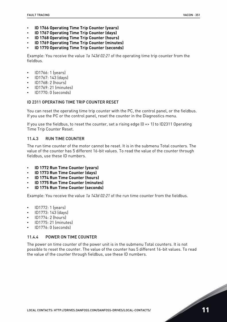
• ID 1766 Operating Time Trip Counter (years)• ID 1767 Operating Time Trip Counter (days)• ID 1768 Operating Time Trip Counter (hours)• ID 1769 Operating Time Trip Counter (minutes)• ID 1770 Operating Time Trip Counter (seconds)
Example: You receive the value 1a 143d 02:21 of the operating time trip counter from thefieldbus.
• ID1766: 1 (years)• ID1767: 143 (days)• ID1768: 2 (hours)• ID1769: 21 (minutes)• ID1770: 0 (seconds)
ID 2311 OPERATING TIME TRIP COUNTER RESET
You can reset the operating time trip counter with the PC, the control panel, or the fieldbus.If you use the PC or the control panel, reset the counter in the Diagnostics menu.
If you use the fieldbus, to reset the counter, set a rising edge (0 => 1) to ID2311 OperatingTime Trip Counter Reset.
11.4.3 RUN TIME COUNTERThe run time counter of the motor cannot be reset. It is in the submenu Total counters. Thevalue of the counter has 5 different 16-bit values. To read the value of the counter throughfieldbus, use these ID numbers.
• ID 1772 Run Time Counter (years)• ID 1773 Run Time Counter (days)• ID 1774 Run Time Counter (hours)• ID 1775 Run Time Counter (minutes)• ID 1776 Run Time Counter (seconds)
Example: You receive the value 1a 143d 02:21 of the run time counter from the fieldbus.
• ID1772: 1 (years)• ID1773: 143 (days)• ID1774: 2 (hours)• ID1775: 21 (minutes)• ID1776: 0 (seconds)
11.4.4 POWER ON TIME COUNTERThe power on time counter of the power unit is in the submenu Total counters. It is notpossible to reset the counter. The value of the counter has 5 different 16-bit values. To readthe value of the counter through fieldbus, use these ID numbers.
FAULT TRACING VACON · 351
LOCAL CONTACTS: HTTP://DRIVES.DANFOSS.COM/DANFOSS-DRIVES/LOCAL-CONTACTS/ 11
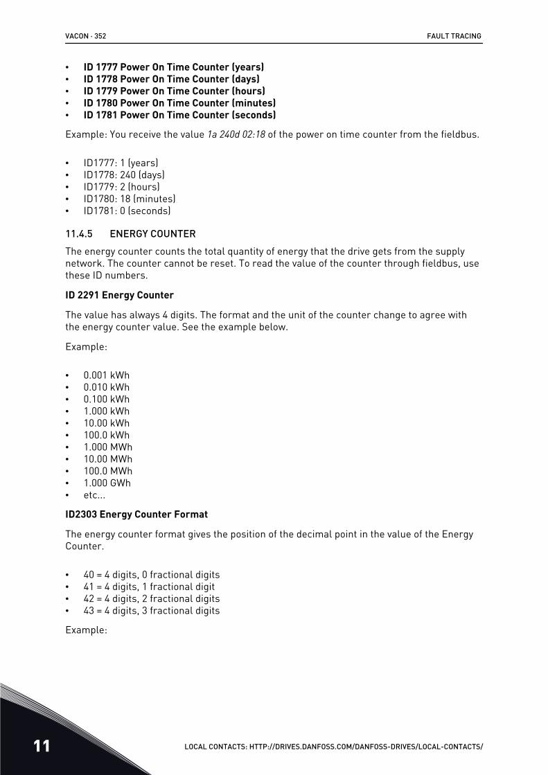
• ID 1777 Power On Time Counter (years)• ID 1778 Power On Time Counter (days)• ID 1779 Power On Time Counter (hours)• ID 1780 Power On Time Counter (minutes)• ID 1781 Power On Time Counter (seconds)
Example: You receive the value 1a 240d 02:18 of the power on time counter from the fieldbus.
• ID1777: 1 (years)• ID1778: 240 (days)• ID1779: 2 (hours)• ID1780: 18 (minutes)• ID1781: 0 (seconds)
11.4.5 ENERGY COUNTERThe energy counter counts the total quantity of energy that the drive gets from the supplynetwork. The counter cannot be reset. To read the value of the counter through fieldbus, usethese ID numbers.
ID 2291 Energy Counter
The value has always 4 digits. The format and the unit of the counter change to agree withthe energy counter value. See the example below.
Example:
• 0.001 kWh• 0.010 kWh• 0.100 kWh• 1.000 kWh• 10.00 kWh• 100.0 kWh• 1.000 MWh• 10.00 MWh• 100.0 MWh• 1.000 GWh• etc...
ID2303 Energy Counter Format
The energy counter format gives the position of the decimal point in the value of the EnergyCounter.
• 40 = 4 digits, 0 fractional digits• 41 = 4 digits, 1 fractional digit• 42 = 4 digits, 2 fractional digits• 43 = 4 digits, 3 fractional digits
Example:
VACON · 352 FAULT TRACING
11 LOCAL CONTACTS: HTTP://DRIVES.DANFOSS.COM/DANFOSS-DRIVES/LOCAL-CONTACTS/
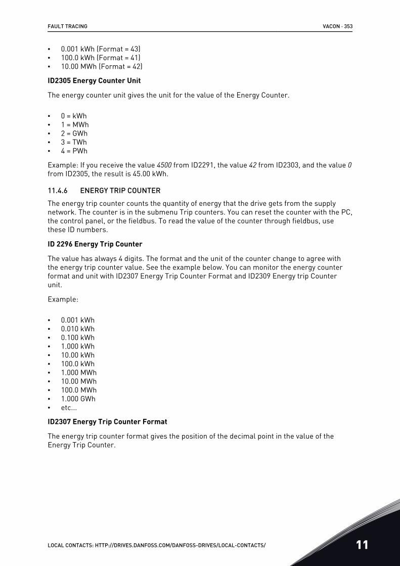
• 0.001 kWh (Format = 43)• 100.0 kWh (Format = 41)• 10.00 MWh (Format = 42)
ID2305 Energy Counter Unit
The energy counter unit gives the unit for the value of the Energy Counter.
• 0 = kWh• 1 = MWh• 2 = GWh• 3 = TWh• 4 = PWh
Example: If you receive the value 4500 from ID2291, the value 42 from ID2303, and the value 0from ID2305, the result is 45.00 kWh.
11.4.6 ENERGY TRIP COUNTERThe energy trip counter counts the quantity of energy that the drive gets from the supplynetwork. The counter is in the submenu Trip counters. You can reset the counter with the PC,the control panel, or the fieldbus. To read the value of the counter through fieldbus, usethese ID numbers.
ID 2296 Energy Trip Counter
The value has always 4 digits. The format and the unit of the counter change to agree withthe energy trip counter value. See the example below. You can monitor the energy counterformat and unit with ID2307 Energy Trip Counter Format and ID2309 Energy trip Counterunit.
Example:
• 0.001 kWh• 0.010 kWh• 0.100 kWh• 1.000 kWh• 10.00 kWh• 100.0 kWh• 1.000 MWh• 10.00 MWh• 100.0 MWh• 1.000 GWh• etc...
ID2307 Energy Trip Counter Format
The energy trip counter format gives the position of the decimal point in the value of theEnergy Trip Counter.
FAULT TRACING VACON · 353
LOCAL CONTACTS: HTTP://DRIVES.DANFOSS.COM/DANFOSS-DRIVES/LOCAL-CONTACTS/ 11
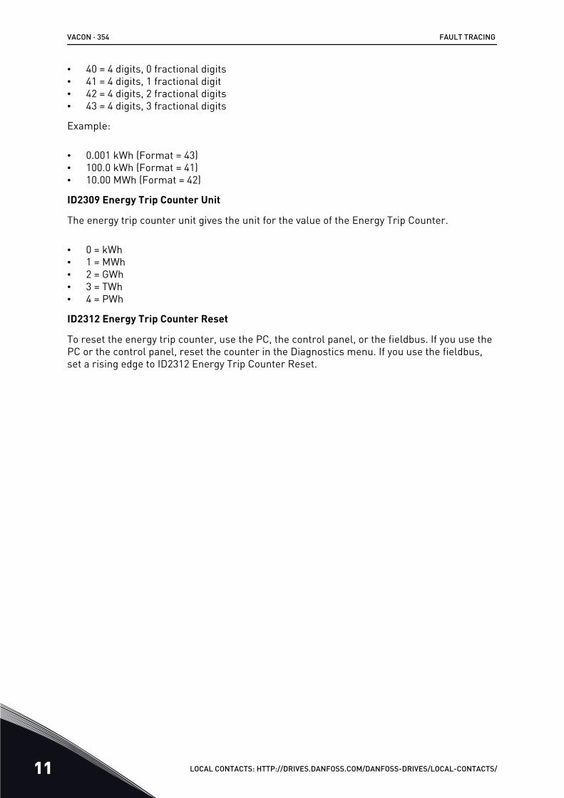
• 40 = 4 digits, 0 fractional digits• 41 = 4 digits, 1 fractional digit• 42 = 4 digits, 2 fractional digits• 43 = 4 digits, 3 fractional digits
Example:
• 0.001 kWh (Format = 43)• 100.0 kWh (Format = 41)• 10.00 MWh (Format = 42)
ID2309 Energy Trip Counter Unit
The energy trip counter unit gives the unit for the value of the Energy Trip Counter.
• 0 = kWh• 1 = MWh• 2 = GWh• 3 = TWh• 4 = PWh
ID2312 Energy Trip Counter Reset
To reset the energy trip counter, use the PC, the control panel, or the fieldbus. If you use thePC or the control panel, reset the counter in the Diagnostics menu. If you use the fieldbus,set a rising edge to ID2312 Energy Trip Counter Reset.
VACON · 354 FAULT TRACING
11 LOCAL CONTACTS: HTTP://DRIVES.DANFOSS.COM/DANFOSS-DRIVES/LOCAL-CONTACTS/

12 APPENDIX 112.1 THE DEFAULT VALUES OF PARAMETERS IN THE DIFFERENT
APPLICATIONS
The explanation of symbols in the table
• A = Standard application• B = Local/ Remote application• C = Multi-step speed application• D = PID control application• E = Multi-purpose application• F = Motor potentiometer application
APPENDIX 1 VACON · 355
LOCAL CONTACTS: HTTP://DRIVES.DANFOSS.COM/DANFOSS-DRIVES/LOCAL-CONTACTS/ 12
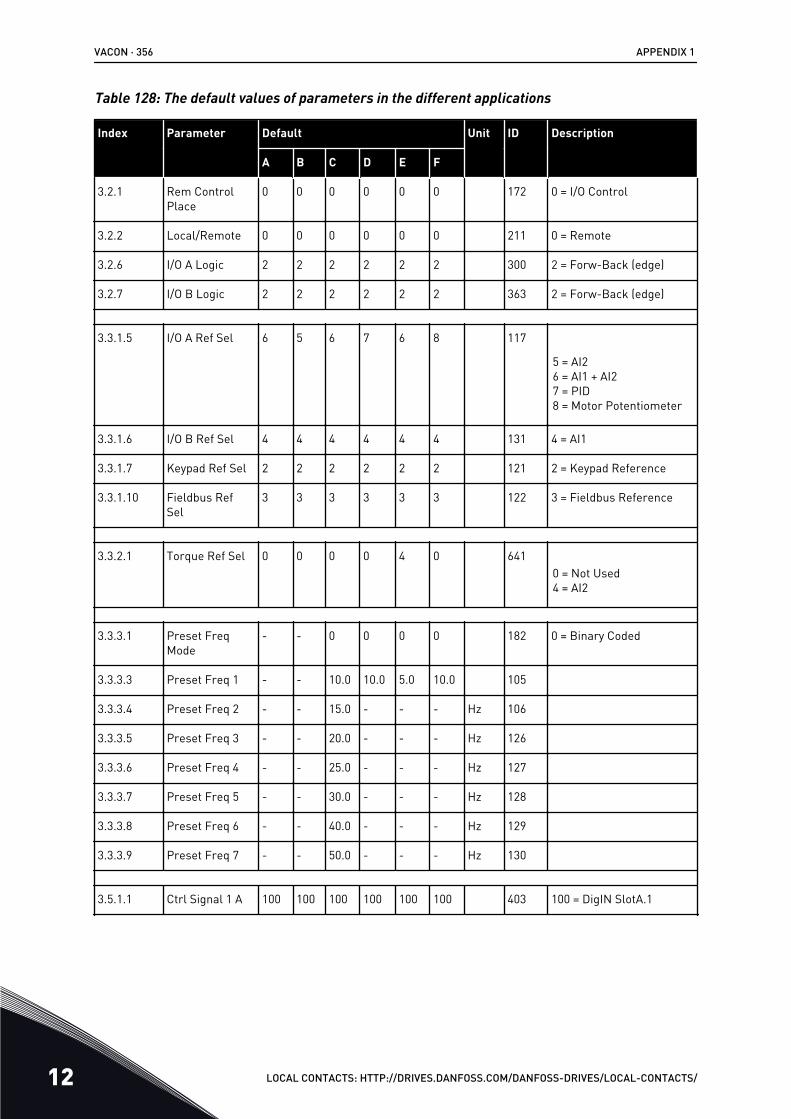
Table 128: The default values of parameters in the different applications
Index Parameter Default Unit ID Description
A B C D E F
3.2.1 Rem ControlPlace
0 0 0 0 0 0 172 0 = I/O Control
3.2.2 Local/Remote 0 0 0 0 0 0 211 0 = Remote
3.2.6 I/O A Logic 2 2 2 2 2 2 300 2 = Forw-Back (edge)
3.2.7 I/O B Logic 2 2 2 2 2 2 363 2 = Forw-Back (edge)
3.3.1.5 I/O A Ref Sel 6 5 6 7 6 8 117
5 = AI26 = AI1 + AI27 = PID8 = Motor Potentiometer
3.3.1.6 I/O B Ref Sel 4 4 4 4 4 4 131 4 = AI1
3.3.1.7 Keypad Ref Sel 2 2 2 2 2 2 121 2 = Keypad Reference
3.3.1.10 Fieldbus RefSel
3 3 3 3 3 3 122 3 = Fieldbus Reference
3.3.2.1 Torque Ref Sel 0 0 0 0 4 0 6410 = Not Used4 = AI2
3.3.3.1 Preset FreqMode
- - 0 0 0 0 182 0 = Binary Coded
3.3.3.3 Preset Freq 1 - - 10.0 10.0 5.0 10.0 105
3.3.3.4 Preset Freq 2 - - 15.0 - - - Hz 106
3.3.3.5 Preset Freq 3 - - 20.0 - - - Hz 126
3.3.3.6 Preset Freq 4 - - 25.0 - - - Hz 127
3.3.3.7 Preset Freq 5 - - 30.0 - - - Hz 128
3.3.3.8 Preset Freq 6 - - 40.0 - - - Hz 129
3.3.3.9 Preset Freq 7 - - 50.0 - - - Hz 130
3.5.1.1 Ctrl Signal 1 A 100 100 100 100 100 100 403 100 = DigIN SlotA.1
VACON · 356 APPENDIX 1
12 LOCAL CONTACTS: HTTP://DRIVES.DANFOSS.COM/DANFOSS-DRIVES/LOCAL-CONTACTS/
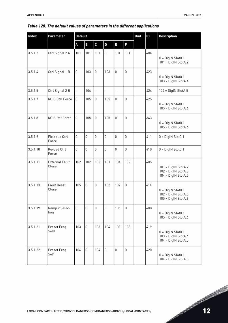
Table 128: The default values of parameters in the different applications
Index Parameter Default Unit ID Description
A B C D E F
3.5.1.2 Ctrl Signal 2 A 101 101 101 0 101 101 4040 = DigIN Slot0.1101 = DigIN SlotA.2
3.5.1.4 Ctrl Signal 1 B 0 103 0 103 0 0 4230 = DigIN Slot0.1103 = DigIN SlotA.4
3.5.1.5 Ctrl Signal 2 B - 104 - - - - 424 104 = DigIN SlotA.5
3.5.1.7 I/O B Ctrl Force 0 105 0 105 0 0 4250 = DigIN Slot0.1105 = DigIN SlotA.6
3.5.1.8 I/O B Ref Force 0 105 0 105 0 0 3430 = DigIN Slot0.1105 = DigIN SlotA.6
3.5.1.9 Fieldbus CtrlForce
0 0 0 0 0 0 411 0 = DigIN Slot0.1
3.5.1.10 Keypad CtrlForce
0 0 0 0 0 0 410 0 = DigIN Slot0.1
3.5.1.11 External FaultClose
102 102 102 101 104 102 405101 = DigIN SlotA.2102 = DigIN SlotA.3104 = DigIN SlotA.5
3.5.1.13 Fault ResetClose
105 0 0 102 102 0 4140 = DigIN Slot0.1102 = DigIN SlotA.3105 = DigIN SlotA.6
3.5.1.19 Ramp 2 Selec-tion
0 0 0 0 105 0 4080 = DigIN Slot0.1105 = DigIN SlotA.6
3.5.1.21 Preset FreqSel0
103 0 103 104 103 103 4190 = DigIN Slot0.1103 = DigIN SlotA.4104 = DigIN SlotA.5
3.5.1.22 Preset FreqSel1
104 0 104 0 0 0 4200 = DigIN Slot0.1104 = DigIN SlotA.5
APPENDIX 1 VACON · 357
LOCAL CONTACTS: HTTP://DRIVES.DANFOSS.COM/DANFOSS-DRIVES/LOCAL-CONTACTS/ 12
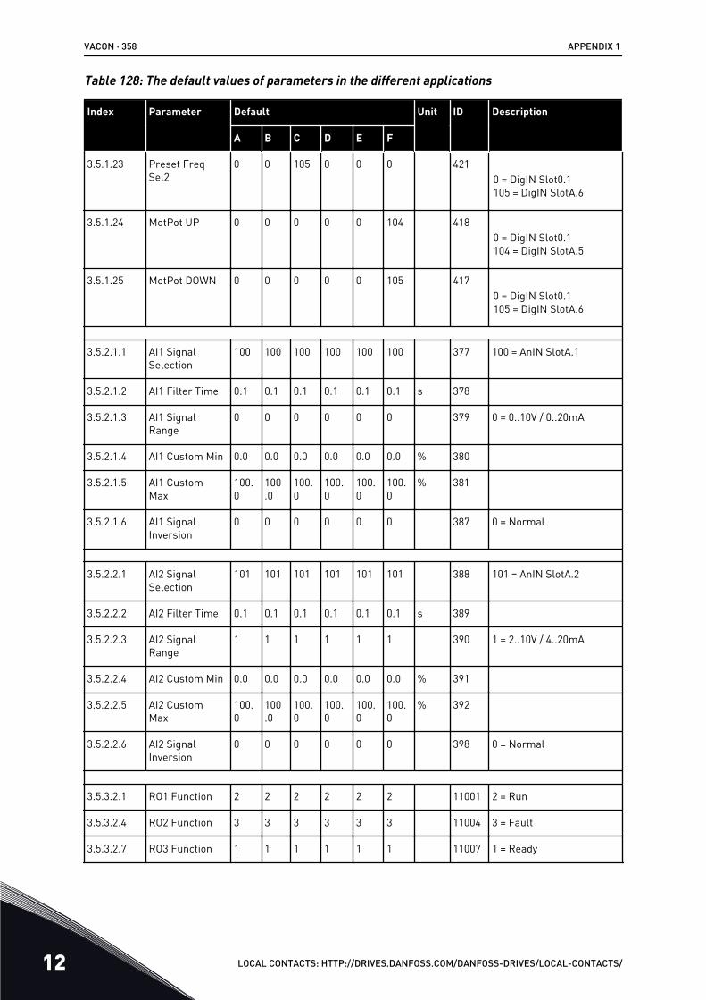
Table 128: The default values of parameters in the different applications
Index Parameter Default Unit ID Description
A B C D E F
3.5.1.23 Preset FreqSel2
0 0 105 0 0 0 4210 = DigIN Slot0.1105 = DigIN SlotA.6
3.5.1.24 MotPot UP 0 0 0 0 0 104 4180 = DigIN Slot0.1104 = DigIN SlotA.5
3.5.1.25 MotPot DOWN 0 0 0 0 0 105 4170 = DigIN Slot0.1105 = DigIN SlotA.6
3.5.2.1.1 AI1 SignalSelection
100 100 100 100 100 100 377 100 = AnIN SlotA.1
3.5.2.1.2 AI1 Filter Time 0.1 0.1 0.1 0.1 0.1 0.1 s 378
3.5.2.1.3 AI1 SignalRange
0 0 0 0 0 0 379 0 = 0..10V / 0..20mA
3.5.2.1.4 AI1 Custom Min 0.0 0.0 0.0 0.0 0.0 0.0 % 380
3.5.2.1.5 AI1 CustomMax
100.0
100.0
100.0
100.0
100.0
100.0
% 381
3.5.2.1.6 AI1 SignalInversion
0 0 0 0 0 0 387 0 = Normal
3.5.2.2.1 AI2 SignalSelection
101 101 101 101 101 101 388 101 = AnIN SlotA.2
3.5.2.2.2 AI2 Filter Time 0.1 0.1 0.1 0.1 0.1 0.1 s 389
3.5.2.2.3 AI2 SignalRange
1 1 1 1 1 1 390 1 = 2..10V / 4..20mA
3.5.2.2.4 AI2 Custom Min 0.0 0.0 0.0 0.0 0.0 0.0 % 391
3.5.2.2.5 AI2 CustomMax
100.0
100.0
100.0
100.0
100.0
100.0
% 392
3.5.2.2.6 AI2 SignalInversion
0 0 0 0 0 0 398 0 = Normal
3.5.3.2.1 RO1 Function 2 2 2 2 2 2 11001 2 = Run
3.5.3.2.4 RO2 Function 3 3 3 3 3 3 11004 3 = Fault
3.5.3.2.7 RO3 Function 1 1 1 1 1 1 11007 1 = Ready
VACON · 358 APPENDIX 1
12 LOCAL CONTACTS: HTTP://DRIVES.DANFOSS.COM/DANFOSS-DRIVES/LOCAL-CONTACTS/
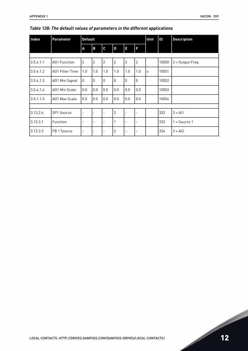
Table 128: The default values of parameters in the different applications
Index Parameter Default Unit ID Description
A B C D E F
3.5.4.1.1 AO1 Function 2 2 2 2 2 2 10050 2 = Output Freq
3.5.4.1.2 AO1 Filter Time 1.0 1.0 1.0 1.0 1.0 1.0 s 10051
3.5.4.1.3 AO1 Min Signal 0 0 0 0 0 0 10052
3.5.4.1.4 AO1 Min Scale 0.0 0.0 0.0 0.0 0.0 0.0 10053
3.5.1.1.5 AO1 Max Scale 0.0 0.0 0.0 0.0 0.0 0.0 10054
3.13.2.6 SP1 Source - - - 3 - - 332 3 = AI1
3.13.3.1 Function - - - 1 - - 333 1 = Source 1
3.13.3.3 FB 1 Source - - - 2 - - 334 2 = AI2
APPENDIX 1 VACON · 359
LOCAL CONTACTS: HTTP://DRIVES.DANFOSS.COM/DANFOSS-DRIVES/LOCAL-CONTACTS/ 12

Document ID:
DPD00927JRev. J
Sales code: DOC-APP100+DLUK
Vacon LtdMember of the Danfoss GroupRunsorintie 765380 VaasaFinland
www.danfoss.com