Embed Size (px)
Citation preview
Safety Vacuum Release System
Installation Instructions
Model VA-2000
Vac-AlertTM Industries, LLC
775 8th Court, Suite 4 Vero Beach, FL 32962
www.vac-alert.com
April 29, 2011
2
o VAC-ALERT MODEL VA-2000L (Lift) The Vac-AlertTM Model VA-2000L is a Safety Vacuum Release System (SVRS) designed for suction lift applications. Suction lift in this case applies to all applications where the circulating pump suction is no more than 24” below, or no more than 42” above the level of the pool or spa water surface. This unit incorporates a 0.170” diameter orifice opening installed below the surge tube section. This orifice opening is sized to prevent nuisance tripping of the SVRS unit caused by high vacuum surges typical of many pump start-up conditions. The Model VA-2000L SVRS unit also utilizes a check valve assembly equipped with a 3.5 pound spring, a poppet disc and a one-way (up only) vented poppet. This check valve assembly permits continued water flow to the circulating pump while the SVRS unit is in the open or vented position. The 3.5 pound spring further compressed by the poppet disc, creates enough sealing force within the check valve to allow partial water flow to the circulating pump for suction lifts up to 42 inches. This is critical to the elimination of circulating pump damage that can be caused by a sustained dry-running condition. The one-way vented poppet allows the surge chamber to be internally recharged when the circulating pump is turned off. This feature prevents nuisance tripping of the SVRS unit on pools and spas that utilize a timer or air switch for circulation pump operation.
o VAC-ALERT MODEL VA-2000S (Submerged) The Vac-AlertTM Model VA-2000S is a Safety Vacuum Release System (SVRS) designed for submerged suction applications. Submerged suction in this case applies to applications where the circulating pump suction is more than 24” below the level of the pool water surface. The Model VA-2000S is recommended on commercial pool applications where the pump has a submerged suction of any depth and runs 24/7. In submerged suction applications, for pumps 10 horsepower and greater, or for pumps located 10 feet or more below the water line, a pump shut-off switch (Model PSAC) is recommended. The Model VA-2000S unit incorporates a 0.375” diameter orifice opening installed below the surge tube section. This orifice opening is sized to provide a limited amount of pump start-up surge protection, while at the same time allowing enough air into the piping system to insure dissipation of the dynamic suction force caused by the circulating pump. The Model VA-2000S SVRS unit also utilizes a check valve assembly equipped with a 0.25 pound spring and a non-vented poppet (no poppet disc or hole through the poppet). This check valve assembly utilizes a light duty spring to minimize the sealing force of the check valve. The non-vented poppet insures that water from the circulating system, under a positive hydrostatic head condition, does not migrate up into the SVRS unit. NOTE: The Model VA-2000 type is indicated on the outside of the box and on the unit itself. Make sure you have the correct Model SVRS for your application! SVRS in these instructions refers specifically to the Vac-AlertTM Model VA-2000.
3
Vac-AlertTM Industries, LLC Model VA-2000
Installation Instructions INTRODUCTION INITIAL SYSTEM PREPARATION Determine whether the installation requires a VA-2000L (suction lift) or a VA-2000S (submerged or flooded suction) SVRS unit. See the preceding page for a more detailed description of each SVRS type. For commercial installations where the circulating pump has a submerged or flooded suction and runs continuously (24/7), the Model VA-2000S is recommended. For submerged or flooded suction installations where the circulating pump is 10 HP or greater, or the pump is located 10 feet or more below the pool or spa water surface, in addition to the installation of a Model VA-2000S unit, a pump shut-off switch (Model PSAC) is recommended. Contact your Vac-AlertTM representative for details on the Model PSAC. The Model VA-2000L is designed for use in installations where a timer or air switch is used to automatically cycle the circulation pump. The VA-2000L unit is to be applied in these applications where the pump is located no more than 24” below, or no more than 42” above the level of the pool or spa water surface. For applications where the pump is located more than 42” above pool or spa water level, contact your Vac-AlertTM representative for further instructions. For applications where the pump is located more than 24” below pool or spa water level, use the VA-2000S SVRS unit. The SVRS unit should be installed on the main drain line. It is not recommended that the SVRS unit be installed on the common header or common line to the pump, where additional skimmer line(s) or vacuum line(s) are also present. The SVRS is designed to protect against main drain suction entrapment, and the unit should be adjusted to the specific hydraulics of the main drain line. Install the SVRS unit per the following instructions and check system vacuum level with all flow from the main drain suction line, i.e. shut-off all other water sources except the main drain suction line. If the main drain line is plumbed through a skimmer, install the SVRS on the line 12” to 18” from the pump where possible. Do not close-couple the SVRS unit to the pump. The skimmer must be blocked to insure all flow is routed from the main drain when determining maximum running vacuum level and during SVRS testing. Using the vacuum gauge on the Model VA-2000, note the level of the operating vacuum. If the vacuum level exceeds 15” Hg, system adjustments to lower the vacuum level will assist with the proper installation of the SVRS unit.
4
Following are suggestions for lowering system operating vacuum levels at an existing pool or spa. 1. Reduce the pump size or reduce the pump impeller diameter 2. Check the main drain line for blockages 3. Replace the drain cover with another cover that has a higher open area 4. Replace return side nozzles with smaller orifices to slow down flow For new construction or a remodel project, increase the diameter of the connector piping and fittings where two or more main drains are employed, and increase the diameter of the main drain suction line to reduce pipe velocity and running vacuum level. Minimize the use of 90 degree elbows and other fittings that increase the system pressure drop. Keep your pipe runs as short as possible. Once the system vacuum level is set at 15” Hg or less, the system can be prepared for SVRS installation. SVRS UNPACKING INSTRUCTIONS The VA2000 SVRS is packaged in a corrugated box with polystyrene upper and lower inserts to protect the unit from damage during shipment. The product serial number is located on the top of the box, and on the upper back side of the unit (ARL Number). Carefully open the top of the box and note that the spanner key is housed in the polystyrene insert – Do not lose or misplace the spanner key. Remove the upper insert after stowing the spanner key and lift the unit by grasping the tee at each end. DO NOT DROP THE UNIT! The Installation Instructions, DVD and Quick Installation Guide are located in the box stowed between the box and the lower polystyrene insert. If the outer package appears to have been damaged during shipment, carefully inspect the unit. Closely inspect the vacuum gauge for possible damage in shipment; if the vacuum gauge is damaged or in need of replacement it can be ordered by calling the factory. The gauge incorporates a ¼” tapered pipe thread end connection which is installed into a stainless steel gauge bushing. The gauge and the bushing are threaded together at the factory with an anaerobic sealant. This sealant hardens and makes the separation of the two parts difficult. The gauge bushing has external straight pipe threads and is threaded into the main body of the unit with a non-hardening sealant. The gauge and bushing together can be easily unthreaded from the main body by rotating the bushing counter clockwise until it is free. The bushing can then be placed in a bench vise and removed from the gauge. SVRS INSTALL REQUIREMENTS Though the SVRS (Safety Vacuum Release System) is easily installed, Vac-AlertTM highly recommends that a licensed contractor or service company install the SVRS. When you properly install a Vac-AlertTM SVRS, you are providing an important layer of protection against dangerous body and limb entrapment situations. This system is not an effective defense against hair entanglement. This device may mitigate evisceration. The Model VA-2000 SVRS unit shall only be installed in

5
conjunction with an ASME/ANSI A112.19.8-2008a or VGB 2008 approved suction fitting(s), or an approved channel drain system at each suction outlet or drain outlet. For newly constructed pools or spas where two or more suction outlets are employed, it is important that the outlets be separated by three feet, with minimum 2-1/2” diameter connector piping and fittings. Larger diameter connector piping and fittings may have to be used to keep connector pipe velocity less than 3 feet per second when all suction outlets are functioning at maximum rated flow. No special tools to install the Vac-AlertTM SVRS are required. Here is what you need: 1. Portable drill with 1” or 1-1/4” hole saw type bit (if installing a snap or clamp-on tee) 2. Hacksaw or PVC pipe cutter 3. Flat bladed screwdriver 4. Small level (used to ensure vertical, level installation of the SVRS unit) 5. PVC primer and glue (medium body suitable for wet or dry field conditions) 6. 6” length of 1-1/2” diameter Schedule 40 PVC pipe (vertical section of pipe installed between SVRS and tee, or SVRS and elbow). 7. Schedule 40 PVC tee fitting (size of suction line) 8. Full-port ball valve, slide gate or butterfly valve, or pole-mounted test mat 9. Standard Schedule 40 PVC fittings necessary to adapt the SVRS to existing piping
10. Spanner tool located in the box insert provided with the SVRS unit. Begin by checking the vacuum levels at each pump. Close off all other secondary lines and check the vacuum level with all flow coming from the main drain line. If the vacuum level is over 15”, see previous suggestions for lowering system running vacuum level. NOTE: Do not use a flow restricted test valve, or a slow acting test valve such as a gate, globe or diaphragm type valve. Use only full-port, fast-acting test valves such as a two-way valve, ball valve, or butterfly valve. A test valve may not be required if the SVRS can be mat tested. Use only a pole-mounted test mat for mat testing of Vac-AlertTM SVRS units. It is recommended that a test valve be installed to facilitate testing and inspection. A test valve may be required by local inspection authorities. Determine the number of pumps and main drain suction lines to be protected. You will need to install a Vac-AlertTM SVRS for each pump plumbed to a dedicated main drain suction line. See enclosed installation diagrams. One Vac-AlertTM SVRS unit can be used on a pool / spa combination where a single circulation pump is employed. In this case the SVRS is located on the common main drain line for both the pool and spa (see installation diagrams). The SVRS can handle a difference of no more than 6” Hg between the operating vacuum level in pool mode, and the operating vacuum level in spa mode. System adjustments may be necessary to insure the two running vacuum levels don’t differ more than 6” Hg. Next, determine the size of the main drain suction piping. Determine the Schedule 40 PVC fittings you will need to adapt the 1-1/2” diameter SVRS connection to the existing piping. The SVRS must be mounted in the vertical position. Some installations may require a Schedule 40 PVC reducing bushing, elbow, and pipe nipples to complete the
6
SVRS installation. Turn off all pump motors and select the best location for SVRS installation. SVRS LOCATION 1. Locate the SVRS on the main drain suction line, between the main drain
and the main drain line isolation valve. Install the SVRS away from the pump suction (12” to 18” where possible). Do not close-couple the SVRS to the pump suction. For new construction installations, the SVRS should be located 18” to 60” from the pump suction on the main drain line. For retrofit installations, the SVRS should be installed 12” from the pump suction, and within 60” of the pump suction inlet whenever possible. See enclosed installation diagrams for further details. Isolate the main drain prior to cutting pipe in a flooded application.
2. Find a six to twelve inch section of pipe where the SVRS can be installed. This location can be either a vertical or horizontal section of pipe. Locate and orient the SVRS away from other valves and high traffic areas. The SVRS can face any direction, but must be installed vertical and level.
SVRS INSTALLATION
1. Install a tee fitting at the optimum horizontal section of pipe location. If a vertical section of pipe is the only option it will require an elbow be used to mount the SVRS off the installed tee. A reducing bushing may also be required to mate the 1-1/2” diameter SVRS to the tee fitting installed. Utilize pipe nipples to join fittings in a close-coupled fashion, as required. Note: A 6” long, 1-1/2” diameter, vertical section of Schedule 40 PVC pipe is to be installed between the SVRS and tee, or the SVRS and elbow. The 6” vertical pipe section has no
bearing on SVRS operation, but is recommended in the event the SVRS unit must be removed or relocated in the future.
2. Install a full port, fast acting test valve (two-way, ball or butterfly) in the main
drain suction line before the tee fitting for the SVRS unit. The test valve should be installed in the main drain suction line between the main drain and the SVRS, within two feet of the Vac-AlertTM unit for ease in testing. A test valve need not be installed if the SVRS is to be mat tested at the main drain. Where hydrostatic valve(s) are present in the circulation system, then the Vac-AlertTM should be mat tested at the main drain at least three times after installation.
3. For existing installations, when a snap tee or clamp-on tee is installed, after the
fittings have dried, use a battery-operated hand drill to drill a 1” or 1-1/4” hole in the suction piping.
4. Install the SVRS unit on the 6” long, 1-1/2” diameter vertical pipe section, and let
all glue joints dry before proceeding to Pump Start-Up Test.
7
PUMP START-UP TEST 1. At this point, the pump start-up vacuum level for the system needs to be determined. Close the SVRS vent by pushing down on the reset lever.
Use the vacuum gauge on the installed SVRS unit to read the pump start-up vacuum level in the main drain line. The peak start-up vacuum level should be read with full prime on the pump, all air bled from the filter system, at maximum return rate of flow, and with all suction flow directed from the main drain. This condition will typically produce the peak vacuum level that the SVRS will be exposed to during pump start-up. Set valves and equipment to the above conditions, and…
Turn on the pump. Observe the SVRS response. Make sure to notice the
peak vacuum level on the SVRS vacuum gauge. If the peak vacuum level exceeds 10” Hg, the SVRS will require adjustment (See Item 2. below).
The Vac-AlertTM SVRS unit is designed for systems that operate at vacuum levels less than 15” Hg. Do not install a Vac-AlertTM SVRS unit on any system that operates at a vacuum level above 15” Hg. See Initial System Preparation for options on how to lower system operating vacuum level.
2. NOTE: Each SVRS comes factory set to remain closed (non-venting) for vacuum levels up to 10” Hg.
If the pump start-up test indicates a vacuum level above 10” Hg, the SVRS
will either leak air into the system momentarily, and then re-seal, or the SVRS may lock open in the venting position. Given a start-up vacuum in excess of 10” Hg, or the SVRS is allowing too much air to leak into the system, the SVRS will need adjustment for site-specific vacuum levels.
If the pump start-up test indicates a vacuum level of less than 10” Hg,
and the SVRS is not leaking air into the system, the SVRS should not need any further adjustment.
SVRS ADJUSTMENT The SVRS is field adjustable for vacuum levels from 0” Hg to 15” Hg. As previously stated each unit is shipped from the factory set at about 10” Hg. To adjust the Vac-AlertTM unit for site-specific vacuum conditions proceed as follows:
1. NOTE -Before making any adjustment to the SVRS spring compression screw, make sure the pump is turned off and the Vac-AlertTM unit is in the open (venting) position. The SVRS can be placed in the open position from the vent end (gray end) by utilizing a screwdriver. Remove the vent screen and place the screwdriver
8
in the hole at the vent end. Push the Vac-AlertTM piston towards the adjustment end until the lockout mechanism is engaged. A clicking sound is heard when the lockout mechanism is engaged.
2. Remove the security cap from the adjustment end (white end with Vac-AlertTM
embossing on body) utilizing the spanner tool shipped with the unit. The security cap is removed by unthreading it, rotating in a counterclockwise direction. Once the security cap is removed, the spring compression adjustment screw is visible inside the Vac-AlertTM body. To adjust this screw, a flat bladed (straight slot) screwdriver is required.
3. With the Vac-AlertTM in the open position, turn the adjustment screw clockwise to
increase spring compression (for higher vacuum operating levels), and counter-clockwise to decrease spring compression (for lower vacuum operating levels).
To adjust the Vac-AlertTM for an operating vacuum level of less
than 5” Hg, rotate the adjustment screw counterclockwise until the screw travel stop (minimum spring compression setting) is reached.
To adjust the SVRS unit for an operating vacuum level of up to
15” Hg, rotate the adjustment screw clockwise until the screw travel stop (maximum spring compression setting) is reached, then back the adjustment screw off counter-clockwise one revolution.
The adjustment screw must be positioned properly between the
two travel stops to set the Vac-AlertTM unit for operating vacuum levels greater than 5” Hg and less than 15” Hg.
NOTE: Always adjust the Vac-AlertTM adjustment screw with the unit in the open (venting) position. The SVRS can be placed in the open position from the vent end (gray end) by utilizing a screwdriver. Remove the vent screen and place the screwdriver in the hole at the vent end. Push the Vac-AlertTM piston towards the adjustment end until the lockout mechanism is engaged. A clicking sound is heard when the lockout mechanism is engaged. Once screw adjustment is made, the SVRS can be returned to the closed position by gently pressing down the reset lever. FINAL ADJUSTMENT 1. The Vac-AlertTM should be adjusted to a spring compression level that ensures the
SVRS unit does not lock open during pump start-up. Do not over tighten the adjustment screw. Adjust the screw in increments of two full rotations, then reset the unit, and retest for air venting. The SVRS should be tested at various adjustment levels to determine the balance point at which venting begins to occur at pump start-up.
2. Once the balance point is determined, the adjustment screw should be positioned
clockwise two (2) full turns beyond this point as the final SVRS setting.
9
SVRS TESTING
With the pump turned on, fully primed, all air bled from the filter, and with suction piping valves set to divert all flow from the main drain…( turn off skimmers and all other ports of suction except the main drain line).
1. Quickly close the test valve to simulate a main drain blockage. A pole-mounted
test mat can also be used to cover the main drain to simulate the same effect. 2. The Vac-AlertTM SVRS should respond instantly to the simulated blockage. The
SVRS should lock in the open position, venting air into the system and dissipating the suction vacuum. A near zero reading on the SVRS vacuum gauge confirms the system is operating properly.
3. Open the test valve or remove the test mat from the main drain, and reset the
SVRS unit by gently pressing down on the reset lever. With the pump turned on, fully primed and air bled from the filter system, simulate the main drain blockage as done in the previous test. The SVRS should respond as before. Repeat this test procedure at least three (3) times to confirm proper operation of the Vac-AlertTM SVRS unit.
FINAL INSTRUCTIONS Important Note: The Vac-AlertTM Model VA-2000L (Lift) SVRS unit is designed to protect against dry running of self-priming pumps where pump suction lift is less than 42”. To make sure the unit is working properly, turn off the pump and place the Vac-AlertTM SVRS unit in the open (venting) position. Wait one minute, then turn the pump on and make sure the pump partially re-primes. Note that partial re-priming may take several minutes for some systems. Once partial re-prime is established, make sure there is a noticeable stream of mixed air/water flow through the pump returning to the pool or spa. For suction lifts over 42”, or suction lift conditions where partial re-priming does not occur, even after several minutes of pump running time, call Vac-AlertTM Customer Service for further instructions. Reset the SVRS unit to the closed (non-venting) position before returning the system to normal operation. The Vac-AlertTM SVRS unit is provided with a vent screen and an adjustment screw security cap. These must both be installed and properly tightened to complete the installation. It is critical that both of these covers be in place to ensure ongoing safe operation of the SVRS unit.
The security cap is threaded into place utilizing the spanner tool
provided with the unit.
The vent screen is installed with a press fit covering the vent hole on the vent end (gray end) of the SVRS unit. The vent screen should be pushed into place so that the vent screen flange is flush to the vent
10
end (gray end) surface. A screwdriver can be used to press this screen into final position. Care must be taken to avoid bending or crushing the vent screen.
Each SVRS unit is provided with a Vac-AlertTM Field Test Data Sheet that must be completed. Fill out this form and fax or mail it to Vac-AlertTM Industries as instructed on the form. It is critical that this form be completed and all of the information requested supplied. The Vac-AlertTM SVRS must be routinely tested to ensure ongoing safe operation of the unit. It is required that the SVRS be tested, per the prescribed testing procedures, prior to the start of each swimming season, and recommended thereafter at least once per month while the pool or spa remains in use by the end user.
IMPORTANT NOTICES INSTALLER AND USER MUST READ!
1. Locate the Vac-AlertTM SVRS on the main drain suction line. The SVRS must be mounted in the vertical position. All SVRS units shall be field adjusted to site-specific hydraulic conditions. Once adjusted the SVRS unit must be tested three times by simulating an entrapment event. 2. A fast acting, full-flow, full-port two-way valve, ball valve or butterfly valve, installed within two feet of the SVRS unit, can serve as a test valve. A test valve is an optional alternative to a pole-mounted test mat. Each Vac-AlertTM SVRS unit must be tested three (3) times to ensure proper adjustment and operation. Where a hydro- static valve is present, the SVRS must be mat tested. 3. This SVRS unit must be routinely tested. The Vac-AlertTM SVRS unit must be tested at the start of each swimming season, and recommended thereafter at least once per
month while the pool or spa remains in use by the end user. 4. For multiple pump systems, one (1) Vac-AlertTM SVRS unit is required for each pump plumbed to a dedicated main drain suction line. 5. The Vac-AlertTM SVRS unit is rated for suction vacuum levels up to 15 inches of Hg
(mercury). For vacuum levels above 15 inches of Hg, see Initial System Preparation instructions for recommendations on how to lower system operating vacuum level.
6. WARNING: Check valves and obstructions located between the main drain(s) and the Vac-AlertTM SVRS must be removed from the suction system. Do not install (must be removed from existing systems) a check valve in a main drain line between the main drain(s) and the SVRS. A check valve may be installed in the main drain suction line between the SVRS connection tee and the circulation pump. Also, check valves may be installed anywhere on the return side of the pump. The Vac-AlertTM SVRS may be used with hydro-static valves, but a mat test of the SVRS operation is required if a hydro-static valve is present.
11
7. This product, when installed in accordance with manufacturer’s instructions, is designed to protect against injury caused by body or limb entrapment. This device is not designed for protection against hair entanglement. It may mitigate evisceration. The Model VA-2000 must be installed in conjunction with an ASME/ANSI A112.19.8-2008a or VGB 2008 approved suction fitting(s), or an approved channel drain system at each suction outlet or drain outlet. 8. Tests conducted by independent, third part laboratory demonstrate that Vac-Alert’s
Model VA-2000 meets or exceeds the performance requirements of ASME/ANSI A112.19.17-2010 and ASTM standard F2387 – Manufactured Safety Vacuum Release Systems.
SVRS USE AND MAINTENANCE: 1. To use the Vac-AlertTM Model VA-2000 properly, and to maintain the unit in good working order, the following should be practiced.
a. Make sure that the vent screen is always in place and is clear of all obstructions or debris. This is critical to ensure that the air vent passageway is kept clear to allow the movement of air into the pump suction piping, in the event of a high vacuum occurrence due to a main drain blockage. b. Using the installed test valve, or a pole-mounted test mat, conduct routine testing of the SVRS device to ensure proper adjustment of the unit. The Vac-AlertTM
Model VA-2000 SVRS unit must be tested at the start of each swimming season, and recommended thereafter at least once per month while the pool or spa remains
in use by the end user. c. If the SVRS does not function properly during a routine test, the device may need further adjustment. Refer to SVRS adjustment procedures detailed herein, and follow these procedures to re-adjust the SVRS unit. Test the SVRS unit three (3) times after re-adjustment to ensure proper SVRS operation. A mat test is required for those installations where a hydro-static valve is present. Should the SVRS unit still not operate properly, immediately shut down the pool or spa, and call your local pool/spa professional, or call Vac-AlertTM Customer Service for referral to your nearest dealer. d. Make sure the security cap is always installed to guard against unauthorized tampering with SVRS adjustment. 2. The SVRS unit requires no lubrication, no oil, and no grease for proper operation. Do not apply any oil, grease or lubricant, on or in this SVRS device. Do not obstruct the vent screen on the SVRS unit with any foreign material, such as paint, aerosol sprays or adhesive tape.
12
3. The internal main body of the Model VA-2000 SVRS unit is not designed for field repairs. The unit must be routinely tested as detailed herein, and a unit not operating properly should be reported immediately. The following external parts may need replacement over time depending upon environmental exposure and use: a. Vacuum Gauge (0” to 30” Hg)……………....………….….….VA-2680 b. Adjustment Screw Security Cap………………………….……VA-2900 c. Security Cap Key (Hexagonal Spanner Tool)…………….……VA-2970 d. End Cap Vent Screen…………………………………………..VA-2850 e. Check Valve Spring (Suction Lift @ 3.5 lb)…………………...VA-2320-3.5 f. Check Valve Spring (Submerged Suction @ 0.25 lb)……….....VA-2320S-.25 g. Check Valve Poppet (Suction Lift – Vented)……………...…..VA-2870L-P h. Check Valve Poppet (Submerged Suction – Non-Vented)...…..VA-2875S-P To order any of the above parts, call your local pool service company, or call Vac-AlertTM Customer Service for referral to your nearest dealer. 4. The Model VA-2000 SVRS unit should always operate in a dry state. Any indication that the unit is flooded or water logged, as evidenced by water leakage from the SVRS unit, requires immediate service attention. Immediately shut down the pool or spa, and call your local licensed service company, or call Vac-AlertTM Customer Service for referral to your nearest dealer. 5. The Model VA-2000 meets or exceeds the twelve hour -40 F & +140 F temperature
performance testing set by the ASME/ANSI A112.19.17-2010 Standard for Manufacturing Safety Vacuum Release Systems. We strongly suggest that the VA-2000 not be left in below freezing temperatures where the circulation system is not continually running or not protected by a pump house. In such cases, condensation could freeze piping and ice may impair or disable the safety features of the VA-2000. For installations that require winterization, the Model VA-2000 should be removed and stored, and then re-installed upon system start-up.”
FOR CUSTOMER SERVICE IN FLORIDA & U.S. EAST COAST CALL: 1-877-978-0130
FOR CUSTOMER SERVICE IN ALL OTHER U.S. AREAS CALL:
1-800-374-7405
Dated: April 29, 2011
14
������������������������������������������
�������������������������������
������������������������������������������������������������������������������������������������������������������������������������������������������������������������������������������������������������������
l������������������������m������������m�����������������������m��������������������������������m����������������������������������
l�����������������������������������������������������������������������������������������������������������������������������������������������������������������������������������������������������������������������������������
l������������������������������������������������������������������������������������������������������������������������������������������������������������������������������
l�������������������������������������������������������������������������������������������������������������������������������������������������
�����������������������������������
���������������������������������������������������������������������������������������������������������������������������������������������������������������������������������������������
����������������������������������������������������������������������
�����������������������������������������������������������������������
������������������������������������
������������������������������������������������������������������������������������������������������������������������������������������������������������������������������������������������������������������������������������������������������������������������������������������������������������������������������
������������������������������������������������������
�����������������������������������������������������
�����������������������������������������������������������������������������������������
l�������������������������������������������m�������������m��������������������������������������������
�������������������m�������������������������������������������
�����������������������������������������
l������������������������������������������������������������������������������������������������������������������������������������������
l���������������������������������������������������������������
����������������������������������

������������������������������������������
�������������������������������
���������������������������������������������������������������������������
����������������������
����������������������������������������������������������������������������������������������
����������������������������������������������������������������������������������������������������������������������������������������������������������������������������������������������������������������������������������������������������������������������������
������������������������������������������������������������������������
����������������������
������������������������������������������������������������������������������������������������������������������������������������������������������������������������������������������������������
��������
l��������������������������������������������������������������������������������������������������������������������������������������������������������������������������������������������
l����������������������������������������������������������������
l������������������������������������������������������������������������������������������������������������������������������������������������������������������������������������������������������������������������������������������������
�����������������������������������������������������������������������������
���������������������������
���������������������������������������������������������������
���������������������������������������������������������������������������������������������������������������������������������������������������������������������������������������������������������������������������������������������������������������������������������������������������������������
��������������������������������������������������������������������������������������������������������
���������������������������������������������
��������������������
���������
��������������������������������
��������������������������������������������������������������������������������������������������������
�������������������������������������
����������������������������������������������������������������
VAC
-ALE
RT
™ I
ND
UST
RIE
S,
LLC
AS
SU
RAN
CE
OF Q
UALIT
YD
ear
Vac-
Ale
rt S
afet
y Sy
stem
Ow
ner,
Y
our
new
Vac
-Ale
rt S
yste
m h
as p
asse
d a
rigo
rous
qua
lity
cont
rol p
roce
dure
and
is in
con
form
ance
with
the
ASM
E/A
NSI
A11
2.19
.17
and
AST
M
F23
87 s
tand
ards
for
man
ufac
ture
d Sa
fety
Vac
uum
Rel
ease
Sys
tem
s (S
VR
S).
If y
ou f
eel
this
uni
t is
def
ectiv
e or
dam
aged
due
to
ship
ping
or
hand
ling,
it
is y
our
oblig
atio
n to
cal
l: 1
-800
-374
-740
5 an
d sp
eak
to o
ur t
echn
ical
sup
port
sta
ff t
o an
swer
any
que
stio
ns y
ou m
ay h
ave.
Thi
s sy
stem
req
uire
s N
O
lubr
icat
ion
wha
tsoe
ver.
Lub
rica
ting
this
uni
t may
cau
se fa
ilure
and
will
voi
d w
arra
nty.
Vac
-Ale
rt a
ssum
es n
o lia
bilit
y or
res
pons
ibili
ty im
plie
d or
oth
erw
ise
if th
is s
yste
m is
lubr
icat
ed. W
e hi
ghly
rec
omm
end
the
use
of a
n A
SME
/AN
SI A
112.
19.8
app
rove
d m
ain
drai
n co
ver
in c
onju
nctio
n w
ith th
is s
yste
m. T
his
syst
em is
not
an
effe
ctiv
e de
fens
e ag
ains
t hai
r en
tang
lem
ent.
Thi
s de
vise
may
miti
gate
evi
scer
atio
n. U
nder
no
circ
umst
ance
s sh
ould
any
chi
ld e
ver
be le
ft
unat
tend
ed a
t or
by a
ny b
ody
of w
ater
. Nev
er s
it, la
y or
sw
im n
ear
or b
y su
ctio
n po
rts,
suc
tion
fittin
gs o
r m
ain
drai
ns.
TH
IS P
ROD
UCT
IS 3
RD
PAR
TY
TE
ST
ED
TO C
ON
FOR
M T
O
ASM
E/A
NSI
A112.1
9.1
7 A
ND
AST
M F
2387 S
TAN
DAR
DS
____
____
____
____
____
____
____
____
___
Dat
e of
Ins
talla
tion
This
uni
t is
war
rant
ed fr
ee o
f def
ects
for
a pe
riod
of t
hree
yea
rs. T
his
war
rant
y ap
plie
s to
ori
gina
l pur
chas
er o
nly.
Thi
s un
it w
ill b
e re
pair
ed o
r re
plac
ed a
t the
dis
cret
ion
of V
ac-A
lert
™ I
ndus
trie
s, L
LC, p
rovi
ded
it is
ret
urne
d to
the
Man
ufac
ture
r F
reig
ht-P
repa
id.
Ple
ase
keep
this
doc
umen
t with
you
r ot
her
impo
rtan
t pap
ers
Vac-
Ale
rt™
Ind
ustr
ies
assu
mes
no
liabi
lity
or r
espo
nsib
ility
if th
is u
nit i
s in
stal
led
impr
oper
ly o
r al
tere
d. W
e re
com
men
d th
is s
yste
m b
e in
stal
led
by a
poo
l/spa
pro
fess
iona
l. Inst
alle
d by
:___
____
____
____
____
___
Dat
e:__
____
____
____
____
__In
stal
ler
ID(
if ap
plic
able
)___
____
____
____
____
____
____
____
____
__ V
ac-A
lert
Uni
t Ser
ial #
____
____
____
____
____
____
____
____
____
____
Vac-
Ale
rt™
Ind
ustr
ies,
LLC
ww
w.v
ac-a
lert
.com
1-80
0-37
4-74
05(t
oll f
ree)
707-
576-
8286
(fa
x)
Rev 1.06
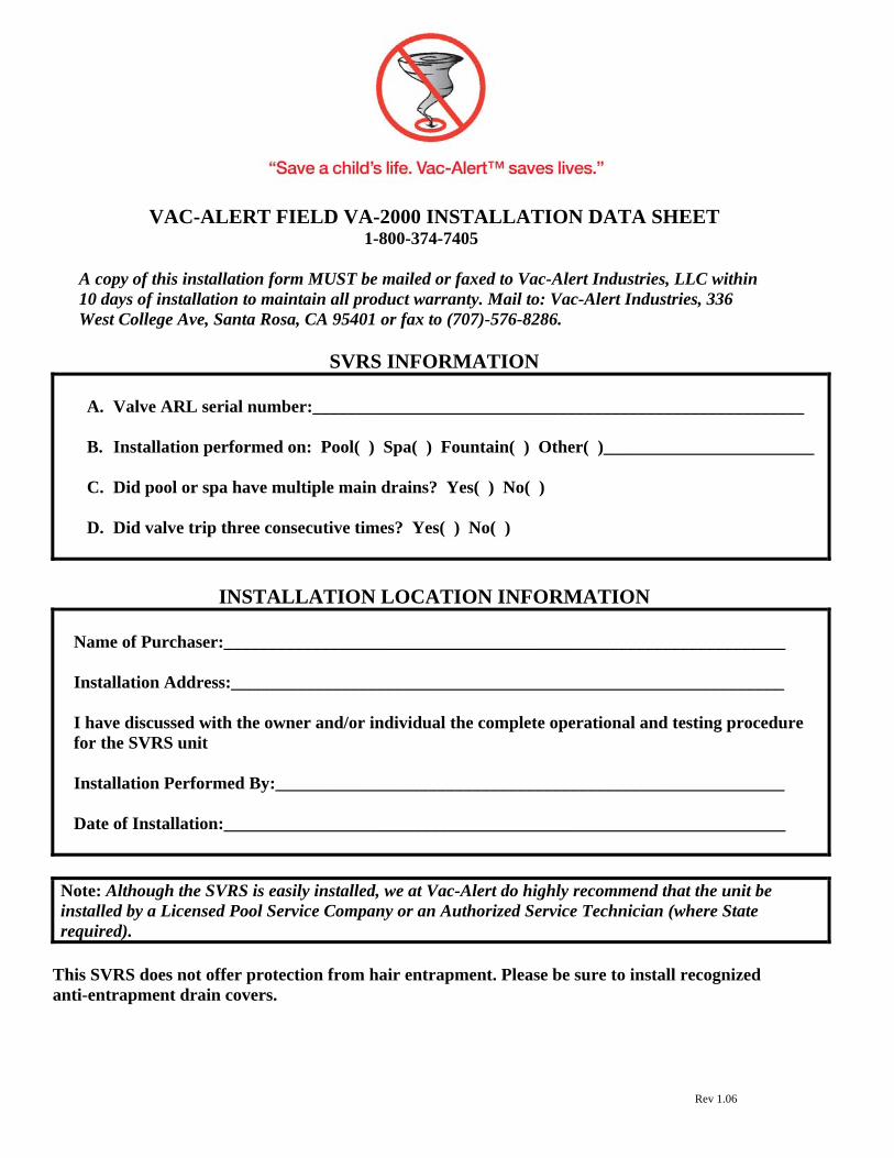
VAC-ALERT FIELD VA-2000 INSTALLATION DATA SHEET 1-800-374-7405
A copy of this installation form MUST be mailed or faxed to Vac-Alert Industries, LLC within 10 days of installation to maintain all product warranty. Mail to: Vac-Alert Industries, 336 West College Ave, Santa Rosa, CA 95401 or fax to (707)-576-8286.
SVRS INFORMATION
A. Valve ARL serial number:________________________________________________________
B. Installation performed on: Pool( ) Spa( ) Fountain( ) Other( )________________________
C. Did pool or spa have multiple main drains? Yes( ) No( )
D. Did valve trip three consecutive times? Yes( ) No( )
INSTALLATION LOCATION INFORMATION Name of Purchaser:________________________________________________________________ Installation Address:_______________________________________________________________ I have discussed with the owner and/or individual the complete operational and testing procedure for the SVRS unit Installation Performed By:__________________________________________________________ Date of Installation:________________________________________________________________
Note: Although the SVRS is easily installed, we at Vac-Alert do highly recommend that the unit be installed by a Licensed Pool Service Company or an Authorized Service Technician (where State required).
This SVRS does not offer protection from hair entrapment. Please be sure to install recognized anti-entrapment drain covers.