Embed Size (px)
Citation preview
VARAN-INTERFACE VAC 013
01.03.2018 Page 1
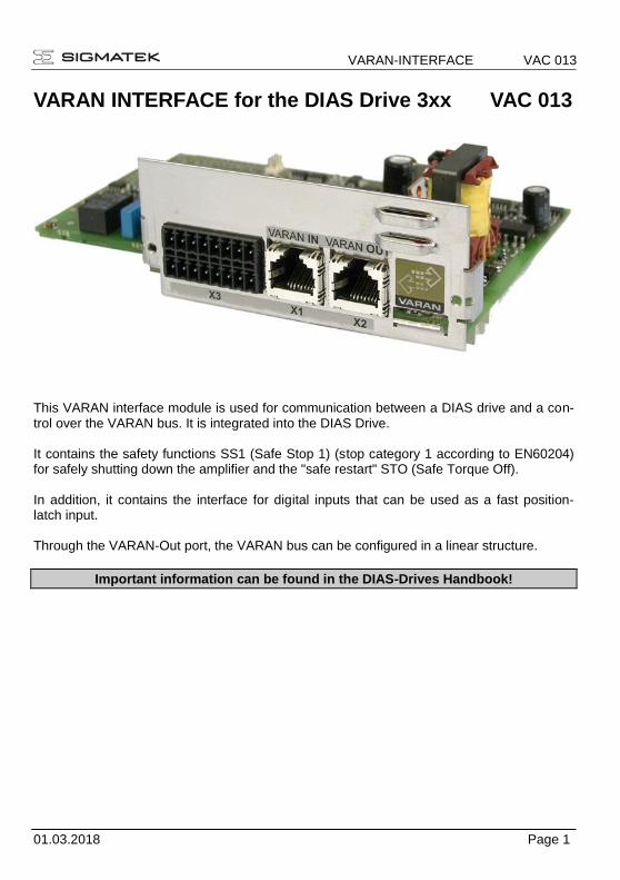
VARAN INTERFACE for the DIAS Drive 3xx VAC 013
This VARAN interface module is used for communication between a DIAS drive and a con-trol over the VARAN bus. It is integrated into the DIAS Drive. It contains the safety functions SS1 (Safe Stop 1) (stop category 1 according to EN60204) for safely shutting down the amplifier and the "safe restart" STO (Safe Torque Off). In addition, it contains the interface for digital inputs that can be used as a fast position-latch input. Through the VARAN-Out port, the VARAN bus can be configured in a linear structure.
Important information can be found in the DIAS-Drives Handbook!
VAC 013 VARAN-INTERFACE
Page 2 01.03.2018
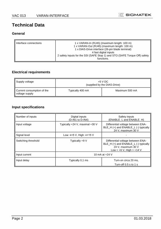
Technical Data General
Interface connections 1 x VARAN-In (RJ45) (maximum length: 100 m) 1 x VARAN-Out (RJ45) (maximum length: 100 m) 1 x DIAS-Drive interface (26-pin blade terminal)
4 fast digital inputs 2 safety inputs for the SSI (SAFE Stop 1) and STO (SAFE Torque Off) safety
functions.
Electrical requirements
Supply voltage +5 V DC (supplied by the DIAS-Drive)
Current consumption of the voltage supply
Typically 400 mA Maximum 500 mA
Input specifications
Number of inputs Digital inputs (D-IN1 to D-IN4)
Safety inputs (ENABLE_L and ENABLE_H)
Input voltage Typically +24 V, maximal +30 V Differential voltage between ENA-BLE_H (+) and ENABLE_L (-) typically
24 V, maximum 30 V
Signal level Low: ≤+5 V, High: ≥+15 V -
Switching threshold Typically +9 V Differential voltage between ENA-BLE_H (+) and ENABLE_L (-) typically
24 V, maximum 30 V Low < +6 V, High > +14 V
Input current 10 mA at +24 V
Input delay Typically 0,1 ms Turn-on circa 20 ms,
Turn-off 0.5 s to 1 s
VARAN-INTERFACE VAC 013
01.03.2018 Page 3
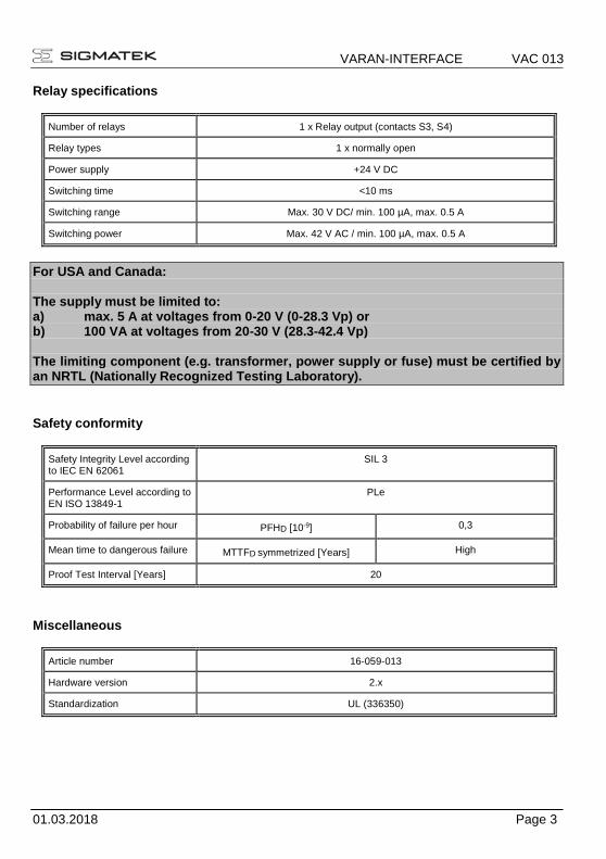
Relay specifications
Number of relays 1 x Relay output (contacts S3, S4)
Relay types 1 x normally open
Power supply +24 V DC
Switching time <10 ms
Switching range Max. 30 V DC/ min. 100 µA, max. 0.5 A
Switching power Max. 42 V AC / min. 100 µA, max. 0.5 A
For USA and Canada: The supply must be limited to: a) max. 5 A at voltages from 0-20 V (0-28.3 Vp) or b) 100 VA at voltages from 20-30 V (28.3-42.4 Vp) The limiting component (e.g. transformer, power supply or fuse) must be certified by an NRTL (Nationally Recognized Testing Laboratory).
Safety conformity
Safety Integrity Level according to IEC EN 62061
SIL 3
Performance Level according to EN ISO 13849-1
PLe
Probability of failure per hour PFHD [10-9] 0,3
Mean time to dangerous failure MTTFD symmetrized [Years] High
Proof Test Interval [Years] 20
Miscellaneous
Article number 16-059-013
Hardware version 2.x
Standardization UL (336350)
VAC 013 VARAN-INTERFACE
Page 4 01.03.2018
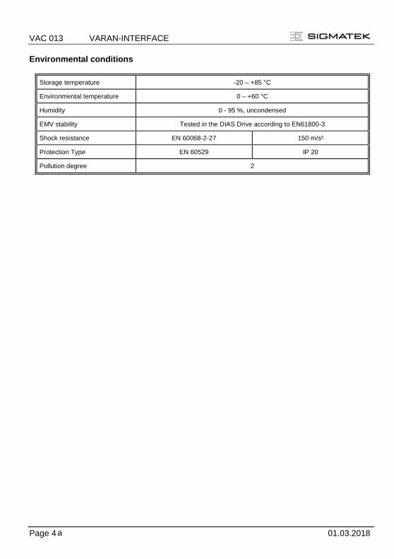
Environmental conditions
Storage temperature -20 – +85 °C
Environmental temperature 0 – +60 °C
Humidity 0 - 95 %, uncondensed
EMV stability Tested in the DIAS Drive according to EN61800-3
Shock resistance EN 60068-2-27 150 m/s²
Protection Type EN 60529 IP 20
Pollution degree 2
a
VARAN-INTERFACE VAC 013
01.03.2018 Page 5
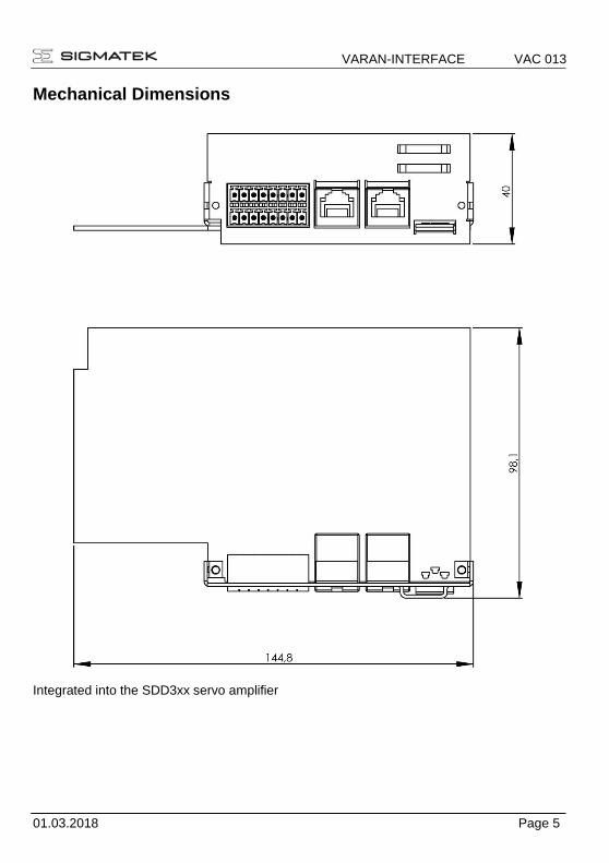
Mechanical Dimensions
Integrated into the SDD3xx servo amplifier
VAC 013 VARAN-INTERFACE
Page 6 01.03.2018
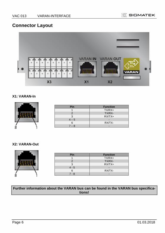
Connector Layout
X1: VARAN-In
X2: VARAN-Out
Further information about the VARAN bus can be found in the VARAN bus specifica-tions!
Pin Function
1 TX/RX+ 2 TX/RX- 3 RX/TX+
4 – 5 - 6 RX/TX-
7 – 8 -
Pin Function
1 TX/RX+ 2 TX/RX- 3 RX/TX+
4 - 5 - 6 RX/TX-
7 - 8 -
VARAN-INTERFACE VAC 013
01.03.2018 Page 7
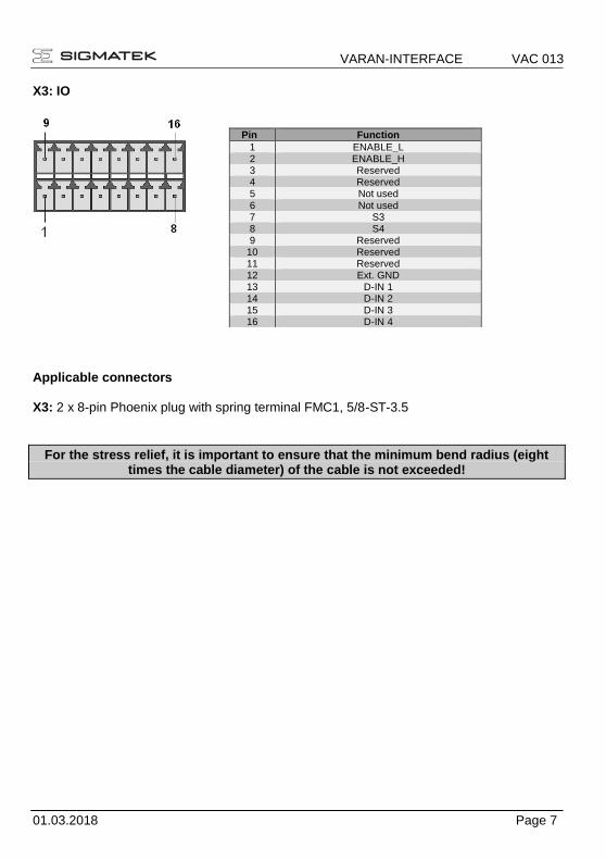
X3: IO
Applicable connectors X3: 2 x 8-pin Phoenix plug with spring terminal FMC1, 5/8-ST-3.5
For the stress relief, it is important to ensure that the minimum bend radius (eight times the cable diameter) of the cable is not exceeded!
Pin Function
1 ENABLE_L 2 ENABLE_H 3 Reserved 4 Reserved 5 Not used 6 Not used 7 S3 8 S4 9 Reserved
10 Reserved 11 Reserved 12 Ext. GND 13 D-IN 1 14 D-IN 2 15 D-IN 3 16 D-IN 4
VAC 013 VARAN-INTERFACE
Page 8 01.03.2018
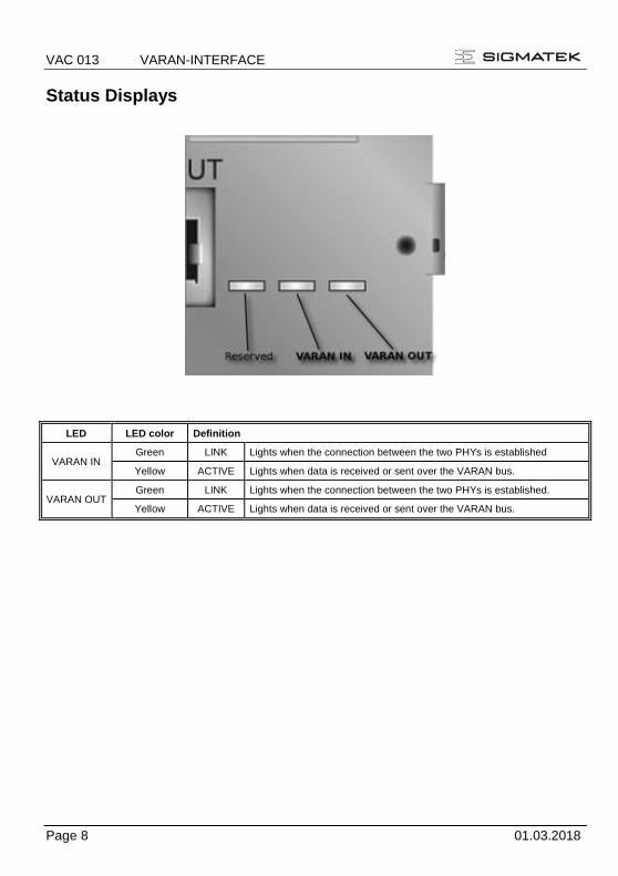
Status Displays
LED LED color Definition
VARAN IN Green LINK Lights when the connection between the two PHYs is established
Yellow ACTIVE Lights when data is received or sent over the VARAN bus.
VARAN OUT Green LINK Lights when the connection between the two PHYs is established.
Yellow ACTIVE Lights when data is received or sent over the VARAN bus.
VARAN-INTERFACE VAC 013
01.03.2018 Page 9
Additional Safety Information The safety module "Safe Restart Lock" in an integral component of the DIAS Drive 3xx and is already installed with delivery; it meets the conditions required for safe operation accord-ing to SIL 3 in compliance with IEC 62061 and according to PL e in compliance with EN 13849-1.
Safety modules can only be powered by supplies that meet the requirements for PELV in compliance with EN60294.
Installation, mounting, programming, initial start-up, operation, maintenance and discarding of safety modules can only be performed by qualified personnel.
Qualified personnel in this context are people, who have completed training or have trained under supervision of qualified personnel and have been authorized to operate and maintain safety-related equipment, systems and facilities in com-pliance with the strict guidelines and standards of safety technology.
For your own safety and the safety of others, use safety modules for their designated purpose.
Designated use also applies to correct EMV installation.
Non-designated use in this context applies to
• Any changes made to the Safety modules or the use of damaged mod-ules
• The use of the Safety modules outside of technical framework described in these operating instructions
• The use of the Safety modules outside of the technical data described in these operating instructions (see the "Technical data" sections of the re-spective production).
In addition, observe the warnings in the other sections of these instruc-tions. These instructions are visibly emphasized with a symbol.
a
VAC 013 VARAN-INTERFACE
Page 10 01.03.2018
• Only qualified personnel are authorized to install the "safe restart" STO (Safe Torque off) and set the parameters.
• All control devices (switches, relays, PLC, etc.) and the control closet must meet the requirements for EN 13849 This consists of:
– Door switches, etc. with at least IP54 protection. – Control classes with at least IP54 protection.
• The proper cables and end-sleeves must be used
• All cables that affect safety (i.e. control cables for the ENABLE_L and ENABLE_H inputs) must be laid in a conduit outside of the control cabi-net. Short or crossed circuits in the signal lines must be avoided! See EN ISO 13849
• The terminal connections X3/Pin 2, Pin 4, Pin 10 and Pin 12 are labeled as reserved and cannot be laid externally!
• When using the SS1 (Safe Stop 1) safety function, the typical turn-off de-lay is 0.5 seconds. Subsequent actions that require the STO (Safe Torque Off) function (i.e. manual access to the machine), can only be released af-ter 1 second.
• If external forces influence axes that are used with the STO safety func-tion (e.g. hanging load), additional measures must be taken (such as an electromagnetic double-surface spring brake, instead of a permanent magnet brake).
Failure to follow the above safety measures can lead to severe injuries.
The main power supply for the servo amplifier must be disconnected using the main switch for the following instances:
• Cleaning, maintenance or repairs
• Extended still-stand periods
Failure to follow the above safety measures can lead to severe injuries.
VARAN-INTERFACE VAC 013
01.03.2018 Page 11
Additional Information
"Safe Restart" STO (Safe Torque Off) The DIAS Drive, in combination with the optional VARAN interface, supports the safety functions SS1 (Safe Stop 1) and STO (Safe Torque Off), and meets the requirements for Category 4 Performance Level "e" according to EN ISO 13849-1 and SIL3 according to EN 62061. For his purpose, the servo amplifier has two safe inputs ENABLE_L und ENABLE_H. The relay output S1/S2 can be used to provide the status of the safety function. It is not safety-relevant, but can be used to test the external safety function. The stop brake control is not a component of the safety function. If a safe shutdown of the stop brake is required, the +24 V-BR brake supply must also be shut down externally. For the 24 V supply, only PELV/SELV can be used.
VAC 013 VARAN-INTERFACE
Page 12 01.03.2018
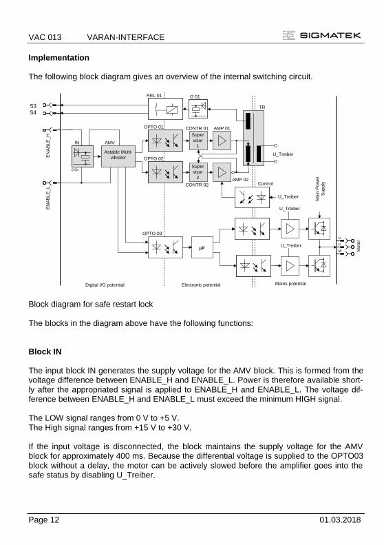
Implementation The following block diagram gives an overview of the internal switching circuit.
Moto
r
Main
Po
we
r
Supply
0.5s
µP
EN
AB
LE
_H
EN
AB
LE
_L
Mains potential
UU
VV
WW
Astable Multi-
vibrator
IN AMV
Digital I/O potential
OPTO 01
OPTO 03
Electronic potential
TR
AMP 01
U_Treiber
CONTR 01
CONTR 02
Super
visor
1
Super
visor
2
S1
S2
REL 01 G 01
Control
OPTO 02
AMP 02
U_Treiber
U_Treiber
U_Treiber
Block diagram for safe restart lock The blocks in the diagram above have the following functions: Block IN The input block IN generates the supply voltage for the AMV block. This is formed from the voltage difference between ENABLE_H and ENABLE_L. Power is therefore available short-ly after the appropriated signal is applied to ENABLE_H and ENABLE_L. The voltage dif-ference between ENABLE_H and ENABLE_L must exceed the minimum HIGH signal. The LOW signal ranges from 0 V to +5 V. The High signal ranges from +15 V to +30 V. If the input voltage is disconnected, the block maintains the supply voltage for the AMV block for approximately 400 ms. Because the differential voltage is supplied to the OPTO03 block without a delay, the motor can be actively slowed before the amplifier goes into the safe status by disabling U_Treiber.
S3 S4
VARAN-INTERFACE VAC 013
01.03.2018 Page 13
Blocks AMV, OPTO 01 and OPTO 02 As long as the AMV block is powered by the IN input block, it generates a pulse with a constant frequency that is transmitted to the sequential electronics through blocks OPTO 01 and OPTO 02. Blocks CONTR 01, CONTR 02, AMP 01, AMP 02 and TR These blocks form a safe switching power supply, which generates the driver voltage for U_Treiber through the transformer TR01. It is ensured that the switching supply cannot transmit any energy when no control signal is sent from the AMV block over OPTO 01 and OPTO 02. Blocks G01 and REL01 The relay output S1/S2 is closed when the servo amplifier is supplied with 24 V and the safety function is active. The two blocks are not safety-relevant.
VAC 013 VARAN-INTERFACE
Page 14 01.03.2018
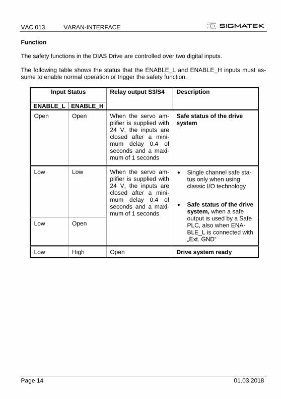
Function The safety functions in the DIAS Drive are controlled over two digital inputs. The following table shows the status that the ENABLE_L and ENABLE_H inputs must as-sume to enable normal operation or trigger the safety function.
Input Status
Relay output S3/S4 Description
ENABLE_L ENABLE_H
Open Open When the servo am-plifier is supplied with 24 V, the inputs are closed after a mini-mum delay 0.4 of seconds and a maxi-mum of 1 seconds
Safe status of the drive system
Low Low When the servo am-plifier is supplied with 24 V, the inputs are closed after a mini-mum delay 0.4 of seconds and a maxi-mum of 1 seconds
• Single channel safe sta-tus only when using classic I/O technology
• Safe status of the drive system, when a safe output is used by a Safe PLC, also when ENA-BLE_L is connected with „Ext. GND“
Low Open
Low High Open Drive system ready
VARAN-INTERFACE VAC 013
01.03.2018 Page 15
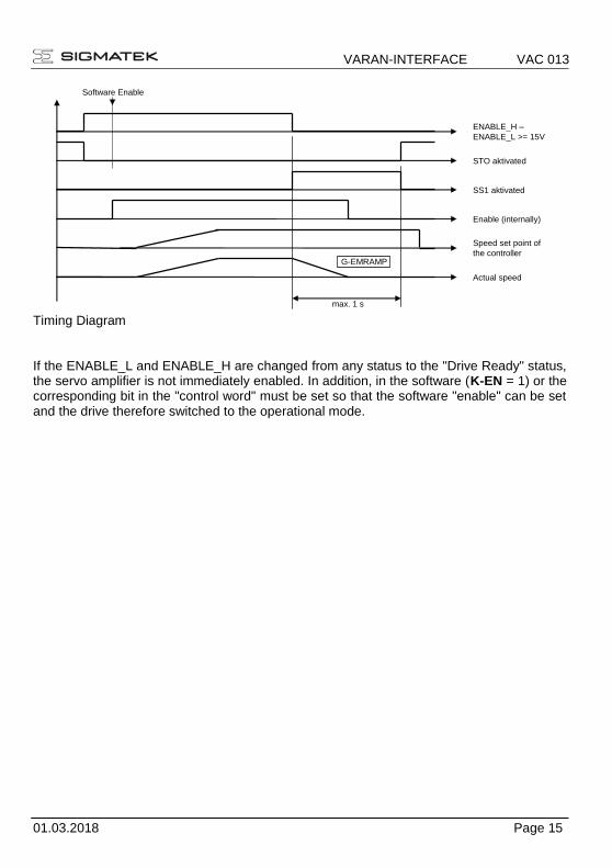
ENABLE_H –
ENABLE_L >= 15V
STO aktivated
Enable (internally)
Software Enable
Speed set point of
the controller
Actual speed
max. 1 s
G-EMRAMP
SS1 aktivated
Timing Diagram If the ENABLE_L and ENABLE_H are changed from any status to the "Drive Ready" status, the servo amplifier is not immediately enabled. In addition, in the software (K-EN = 1) or the corresponding bit in the "control word" must be set so that the software "enable" can be set and the drive therefore switched to the operational mode.
VAC 013 VARAN-INTERFACE
Page 16 01.03.2018
Function Test
The safety function test is required to ensure correct operation. The entire safety circuit must be tested for full functionality. Tests must be performed at the following times:
• After installation
• In regular intervals, or at least once a year.
If the function test results in an invalid machine status, the error must be found and correct-ed before the safety function is retested. If the error reoccurs during the function test, the machine can no longer be operated.
Failure to follow the above safety measures can lead to severe injuries and damage. Test conditions The total safety circuit must be tested for functionability The function test is performed from the following start condition:
- An operation-ready servo drive system - Safe input ENABLE_L is LOW and ENABLE_H is HIGH - Software application is running - Motor(s) running
Depending on the wiring:
1. Both the ENABLE_L and ENABLE_H inputs are opened or if ENABLE_L is connected to "Ext. GND" and the safe output of a Safety PLC is used for ENABLE_H. 2. ENABLE_H is open or LOW (depending on the wiring).
The motor speed is expected to slow to null and the relay output S1/S2 to close after a minimum delay of 0.4 s and a maximum of 1s when the servo drive is supplied with 24 V. The servo drive system should go into safe mode.
VARAN-INTERFACE VAC 013
01.03.2018 Page 17
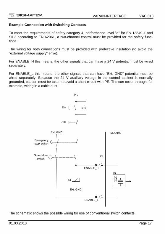
Example Connection with Switching Contacts To meet the requirements of safety category 4, performance level "e" for EN 13849-1 and SIL3 according to EN 62061, a two-channel control must be provided for the safety func-tions. The wiring for both connections must be provided with protective insulation (to avoid the "external voltage supply" error). For ENABLE_H this means, the other signals that can have a 24 V potential must be wired separately. For ENABLE_L this means, the other signals that can have "Ext. GND" potential must be wired separately. Because the 24 V auxiliary voltage in the control cabinet is normally grounded, caution must be taken to avoid a short-circuit with PE. The can occur through, for example, wiring in a cable duct.
24V
ENABLE_H
ENABLE_L
5 5
4 4
IN
Ext. GND
Guard door switch
Emergency stop switch
MDD100
Aus
Ein K1
Ext. GND
K1
X1
The schematic shows the possible wiring for use of conventional switch contacts.
VAC 013 VARAN-INTERFACE
Page 18 01.03.2018
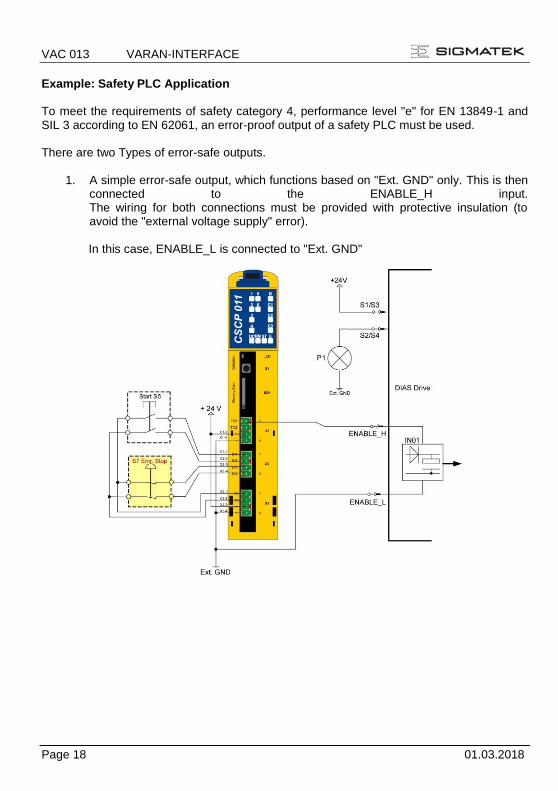
Example: Safety PLC Application To meet the requirements of safety category 4, performance level "e" for EN 13849-1 and SIL 3 according to EN 62061, an error-proof output of a safety PLC must be used. There are two Types of error-safe outputs.
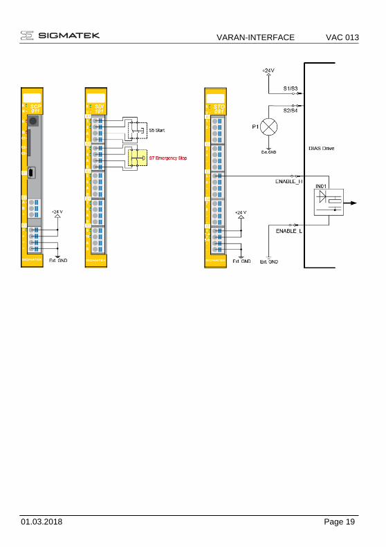
1. A simple error-safe output, which functions based on "Ext. GND" only. This is then connected to the ENABLE_H input. The wiring for both connections must be provided with protective insulation (to avoid the "external voltage supply" error).
In this case, ENABLE_L is connected to "Ext. GND"
VARAN-INTERFACE VAC 013
01.03.2018 Page 19
VAC 013 VARAN-INTERFACE
Page 20 01.03.2018
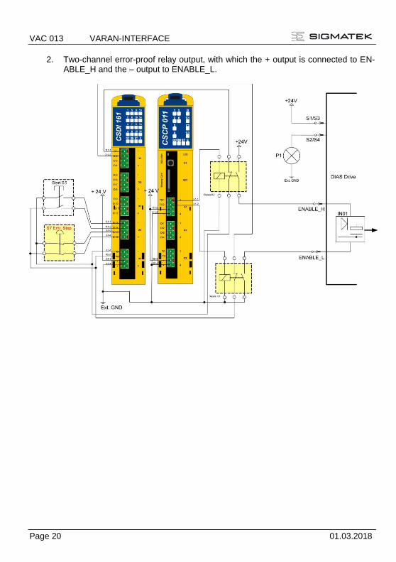
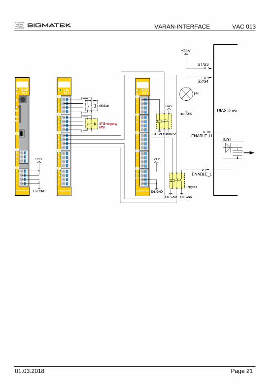
2. Two-channel error-proof relay output, with which the + output is connected to EN-
ABLE_H and the – output to ENABLE_L.
VARAN-INTERFACE VAC 013
01.03.2018 Page 21
VAC 013 VARAN-INTERFACE
Page 22 01.03.2018
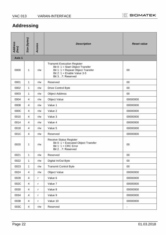
Addressing
Ad
dre
ss
(hex)
Siz
e (
by
tes)
Acce
ss
Description Reset value
Axis 1
0000 1 r/w
Transmit Execution Register Bit 0: 1 = Start Object Transfer Bit 1: 1 = Repeat Object Transfer Bit 2: 1 = Enable Value 3-5 Bit 3…7: Reserved
00
0001 1 r/w Reserved 00
0002 1 r/w Drive Control Byte 00
0003 1 r/w Object Address 00
0004 4 r/w Object Value 00000000
0008 4 r/w Value 1 00000000
000C 4 r/w Value 2 00000000
0010 4 r/w Value 3 00000000
0014 4 r/w Value 4 00000000
0018 4 r/w Value 5 00000000
001C 4 r/w Reserved 00000000
0020 1 r/w
Receive Status Register Bit 0: 1 = Executed Object Transfer Bit 1: 1 = CRC Error Bit 2…7: Reserved
00
0021 1 r/w Reserved 00
0022 1 r/w Digital In/Out Byte 00
0023 1 r/w Transmit Control Byte 00
0024 4 r/w Object Value 00000000
0028 4 r Value 6 00000000
002C 4 r Value 7 00000000
0030 4 r Value 8 00000000
0034 4 r Value 9 00000000
0038 4 r Value 10 00000000
003C 4 r/w Reserved -
VARAN-INTERFACE VAC 013
01.03.2018 Page 23
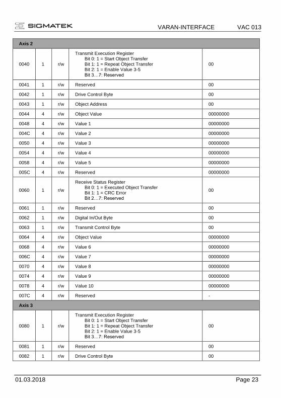
Axis 2
0040 1 r/w
Transmit Execution Register Bit 0: 1 = Start Object Transfer Bit 1: 1 = Repeat Object Transfer Bit 2: 1 = Enable Value 3-5 Bit 3…7: Reserved
00
0041 1 r/w Reserved 00
0042 1 r/w Drive Control Byte 00
0043 1 r/w Object Address 00
0044 4 r/w Object Value 00000000
0048 4 r/w Value 1 00000000
004C 4 r/w Value 2 00000000
0050 4 r/w Value 3 00000000
0054 4 r/w Value 4 00000000
0058 4 r/w Value 5 00000000
005C 4 r/w Reserved 00000000
0060 1 r/w
Receive Status Register Bit 0: 1 = Executed Object Transfer Bit 1: 1 = CRC Error Bit 2…7: Reserved
00
0061 1 r/w Reserved 00
0062 1 r/w Digital In/Out Byte 00
0063 1 r/w Transmit Control Byte 00
0064 4 r/w Object Value 00000000
0068 4 r/w Value 6 00000000
006C 4 r/w Value 7 00000000
0070 4 r/w Value 8 00000000
0074 4 r/w Value 9 00000000
0078 4 r/w Value 10 00000000
007C 4 r/w Reserved -
Axis 3
0080 1 r/w
Transmit Execution Register Bit 0: 1 = Start Object Transfer Bit 1: 1 = Repeat Object Transfer Bit 2: 1 = Enable Value 3-5 Bit 3…7: Reserved
00
0081 1 r/w Reserved 00
0082 1 r/w Drive Control Byte 00
VAC 013 VARAN-INTERFACE
Page 24 01.03.2018
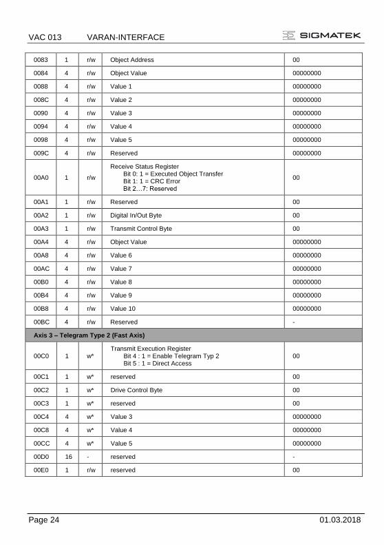
0083 1 r/w Object Address 00
0084 4 r/w Object Value 00000000
0088 4 r/w Value 1 00000000
008C 4 r/w Value 2 00000000
0090 4 r/w Value 3 00000000
0094 4 r/w Value 4 00000000
0098 4 r/w Value 5 00000000
009C 4 r/w Reserved 00000000
00A0 1 r/w
Receive Status Register Bit 0: 1 = Executed Object Transfer Bit 1: 1 = CRC Error Bit 2…7: Reserved
00
00A1 1 r/w Reserved 00
00A2 1 r/w Digital In/Out Byte 00
00A3 1 r/w Transmit Control Byte 00
00A4 4 r/w Object Value 00000000
00A8 4 r/w Value 6 00000000
00AC 4 r/w Value 7 00000000
00B0 4 r/w Value 8 00000000
00B4 4 r/w Value 9 00000000
00B8 4 r/w Value 10 00000000
00BC 4 r/w Reserved -
Axis 3 – Telegram Type 2 (Fast Axis)
00C0 1 w* Transmit Execution Register
Bit 4 : 1 = Enable Telegram Typ 2 Bit 5 : 1 = Direct Access
00
00C1 1 w* reserved 00
00C2 1 w* Drive Control Byte 00
00C3 1 w* reserved 00
00C4 4 w* Value 3 00000000
00C8 4 w* Value 4 00000000
00CC 4 w* Value 5 00000000
00D0 16 - reserved -
00E0 1 r/w reserved 00
VARAN-INTERFACE VAC 013
01.03.2018 Page 25
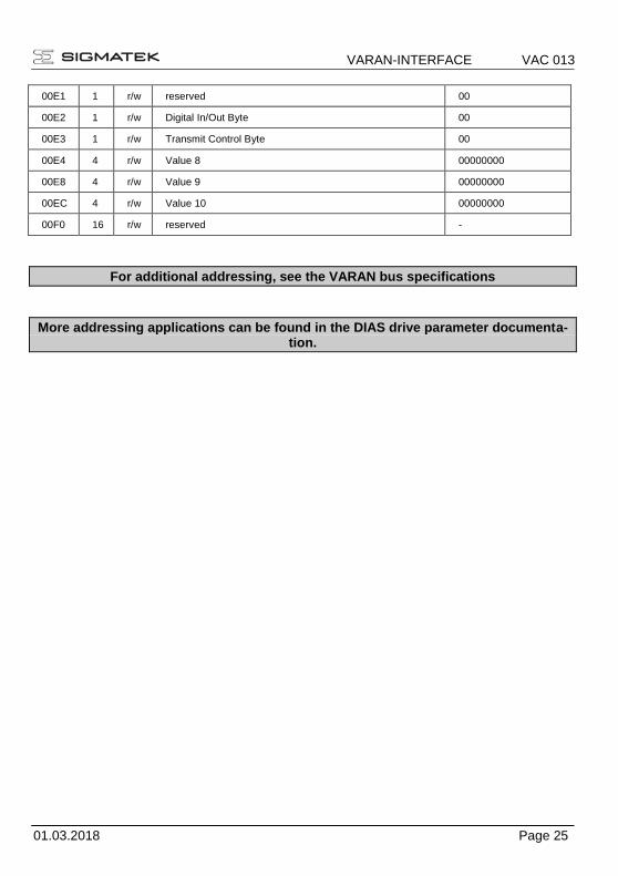
00E1 1 r/w reserved 00
00E2 1 r/w Digital In/Out Byte 00
00E3 1 r/w Transmit Control Byte 00
00E4 4 r/w Value 8 00000000
00E8 4 r/w Value 9 00000000
00EC 4 r/w Value 10 00000000
00F0 16 r/w reserved -
For additional addressing, see the VARAN bus specifications
More addressing applications can be found in the DIAS drive parameter documenta-tion.
VAC 013 VARAN-INTERFACE
Page 26 01.03.2018
Recommended Shielding for VARAN The real-time VARAN Ethernet bus system exhibits very robust characteristics in industrial environments. Through the use of IEEE 802.3 standard Ethernet physics, the potentials between an Ethernet line and sending/receiving components are separated. Messages to a bus participant are immediately repeated by the VARAN Manager in the event of an error. The shielding described below is principally recommended. For applications in which the bus is run outside the control cabinet, the correct shielding is required. Especially when for structural reasons, the bus line must be placed next to strong electromagnetic interference. SIGMATEK recommends the use of CAT5e industrial Ethernet bus cables. For the shielding, an S-FTP cable should be used. An S-FTP bus is a symmetric, multi-wire cable with unshielded pairs. For the total shielding, a combination of foil and braiding is used. A non-laminated variant is recommended.
The VARAN cable must be secured at a distance of 20 cm from the connector for protection against vibration!
VARAN-INTERFACE VAC 013
01.03.2018 Page 27
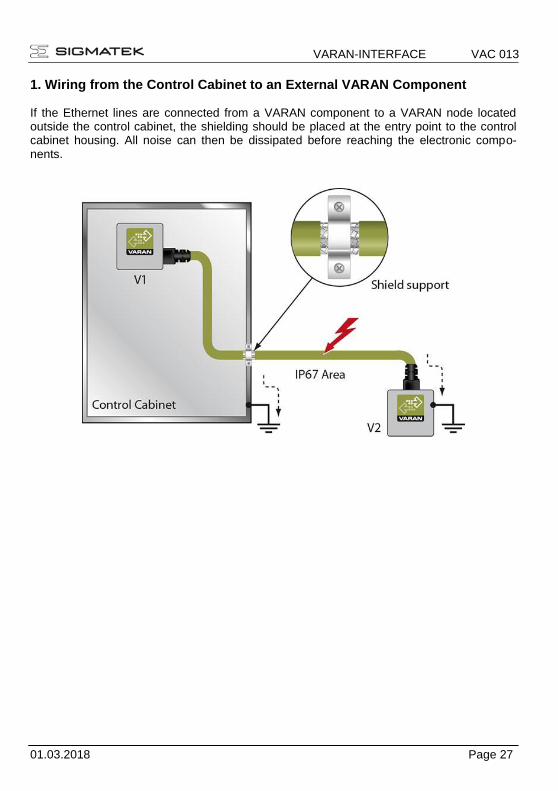
1. Wiring from the Control Cabinet to an External VARAN Component If the Ethernet lines are connected from a VARAN component to a VARAN node located outside the control cabinet, the shielding should be placed at the entry point to the control cabinet housing. All noise can then be dissipated before reaching the electronic compo-nents.
VAC 013 VARAN-INTERFACE
Page 28 01.03.2018
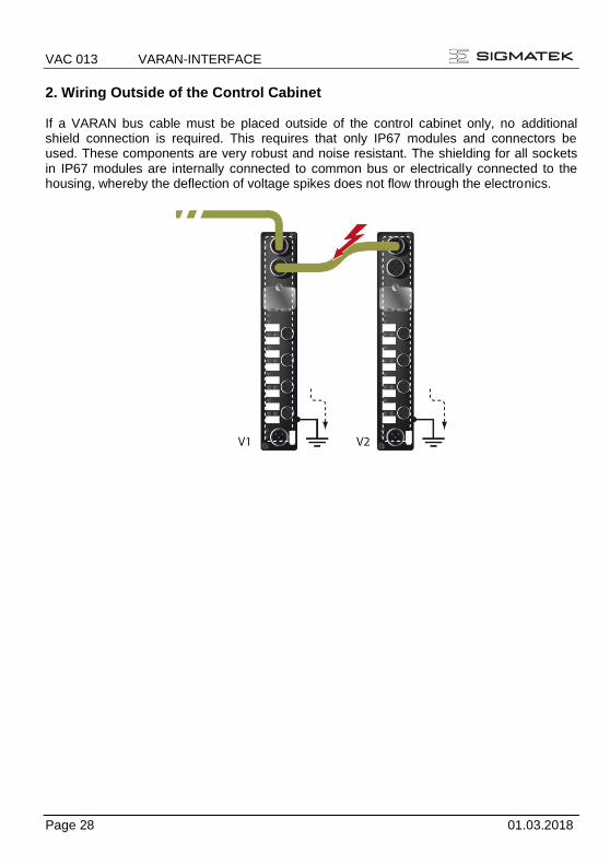
2. Wiring Outside of the Control Cabinet If a VARAN bus cable must be placed outside of the control cabinet only, no additional shield connection is required. This requires that only IP67 modules and connectors be used. These components are very robust and noise resistant. The shielding for all sockets in IP67 modules are internally connected to common bus or electrically connected to the housing, whereby the deflection of voltage spikes does not flow through the electronics.
VARAN-INTERFACE VAC 013
01.03.2018 Page 29
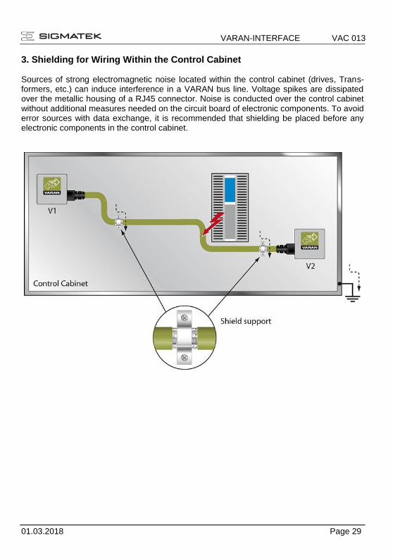
3. Shielding for Wiring Within the Control Cabinet Sources of strong electromagnetic noise located within the control cabinet (drives, Trans-formers, etc.) can induce interference in a VARAN bus line. Voltage spikes are dissipated over the metallic housing of a RJ45 connector. Noise is conducted over the control cabinet without additional measures needed on the circuit board of electronic components. To avoid error sources with data exchange, it is recommended that shielding be placed before any electronic components in the control cabinet.
VAC 013 VARAN-INTERFACE
Page 30 01.03.2018
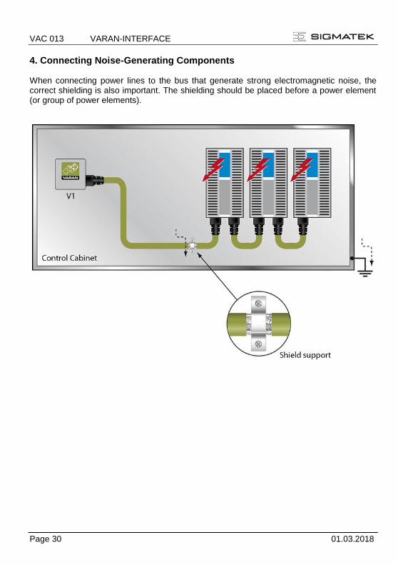
4. Connecting Noise-Generating Components When connecting power lines to the bus that generate strong electromagnetic noise, the correct shielding is also important. The shielding should be placed before a power element (or group of power elements).
VARAN-INTERFACE VAC 013
01.03.2018 Page 31
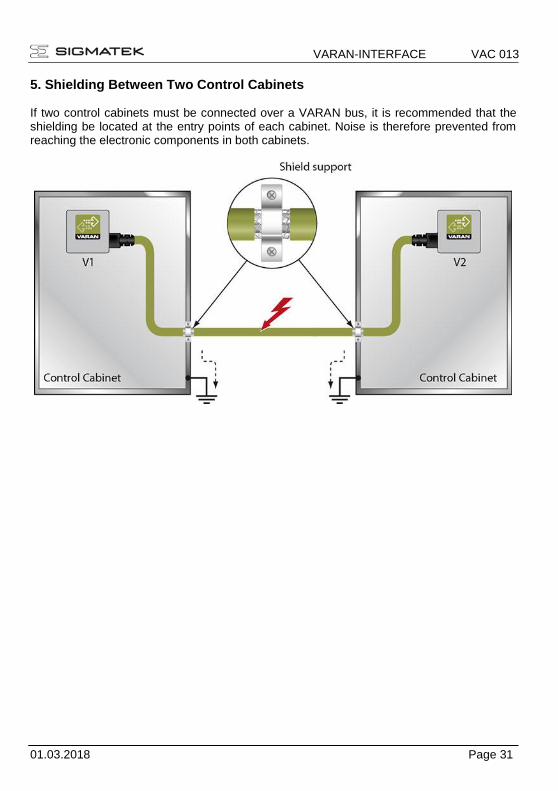
5. Shielding Between Two Control Cabinets If two control cabinets must be connected over a VARAN bus, it is recommended that the shielding be located at the entry points of each cabinet. Noise is therefore prevented from reaching the electronic components in both cabinets.
VAC 013 VARAN-INTERFACE
Page 32 01.03.2018