Embed Size (px)
Citation preview
7/18/2019 V9 Mill-Design Tutorial (metric).pdf
http://slidepdf.com/reader/full/v9-mill-design-tutorial-metricpdf 1/453
Mill/Design
Version 9
Tutorial

7/18/2019 V9 Mill-Design Tutorial (metric).pdf
http://slidepdf.com/reader/full/v9-mill-design-tutorial-metricpdf 2/453
7/18/2019 V9 Mill-Design Tutorial (metric).pdf
http://slidepdf.com/reader/full/v9-mill-design-tutorial-metricpdf 3/453
Version 9 Mill/Design Tutorial(Metric version)
Mastercam Version 9 MillMastercam Version 9 Design© 2002 CNC Software, Inc.

7/18/2019 V9 Mill-Design Tutorial (metric).pdf
http://slidepdf.com/reader/full/v9-mill-design-tutorial-metricpdf 4/453
2 Mastercam Version 8 Lathe Applications Guide

7/18/2019 V9 Mill-Design Tutorial (metric).pdf
http://slidepdf.com/reader/full/v9-mill-design-tutorial-metricpdf 5/453
Mastercam Version 9 Mill/Design Tutorial (Metric version)
Date: January 21, 2002
Copyright © 2002 CNC Software, Inc. - All rights reserved.
First Printing: January 21, 2002
Software: Mastercam Mill Version 9, Mastercam Design Version 9
IMPORTANT NOTICE!
PLEASE READ THIS STATEMENT AND THE SOFTWARE LICENSE AGREEMENT COMPLETELY BEFORE USING THISSOFTWARE.
BY CONTINUING TO USE THIS SOFTWARE, YOU (EITHER AN INDIVIDUAL OR A SINGLE ENTITY) INDICATE YOUR
INTENTION TO BE BOUND BY AND ACCEPT THE TERMS AND CONDITIONS OF THIS SOFTWARE LICENSE. IF YOU DO
NOT AGREE TO THESE TERMS AND CONDITIONS YOU MAY NOT ACCESS OR OTHERWISE USE THIS SOFTWARE AND
WILL IN FACT BE PROHIBITED FROM DOING SO. THIS COMPUTER SOFTWARE MAY BE USED ONLY PURSUANT TO THE
TERMS AND CONDITIONS SET FORTH BELOW, AND SOLELY IN CONJUNCTION WITH THE ACCOMPANYING SECURITY
MECHANISM (UNLESS OTHERWISE SPECIFIED IN THE “EXCEPTIONS TO SECURITY MECHANISM REQUIREMENTS”
SECTION OF SUCH TERMS AND CONDITIONS) WHICH MUST BE PRESENT ON YOUR COMPUTER (OR NETWORK AS
APPLICABLE) AT ALL TIMES DURING SUCH USE.
Software License
CNC Software, Inc. (“CNC”) a Connecticut corporation with its principal place of business at 671 Old Post Rd., Tolland, Connecticut,
06084 hereby grants to you a non-exclusive, non-transferable license (the “License”) to use (and, if applicable, to permit your authorized
employees to use), solely in accordance with the terms and conditions of this Software License Agreement, this software program (the
“Program”) and any accompanying documentation (the “Documentation”) solely for your internal business purposes and solely in
conjunction with the accompanying hardware or software device, method, scheme or other security measure provided by CNC which allowsa user to access the Program and prevents unauthorized access to the Program (the “Security Mechanism”). (The Program, any updates to
the Program, and the Documentation shall hereinafter collectively be referred to as the “Software”).
Restrictions
You may not use the Program without a Security Mechanism provided by CNC or CNC’s suppliers. When CNC or CNC’s suppliers provide
you with a single-user Security Mechanism, the Program may only be used (in executable code form only) on a single computer to which
the Security Mechanism is directly attached. In the event CNC or CNC’s suppliers provide you with a multiple-user Security Mechanism
for use over an internal network (a “Network Security Mechanism”), the Program may be used: (a) in executable code form only; (b) only
on end-user computers that are connected to the internal network to which the Network Security Mechanism is attached; and (c) only by the
number of users and accessed by the number of end-user computers for which licenses were purchased and as further allowed by the
Network Security Mechanism. You may physically transfer the Program from one computer equipped with a single-user Security
Mechanism to another only if the Security Mechanism is included in the transfer and is installed with the new computer.
You shall not: (a) copy (except as provided below), adapt, modify the Software; (b) publish, display, disclose or create a derivative work
from the Software or any part thereof; (c) de-compile or translate, disassemble, create or attempt to create, by reverse engineering or
otherwise, the source code form of the Program from the executable code of the Program; (d) remove any proprietary notices, labels or
marks from the Software; (e) rent, lease, distribute or transfer all or any part of the Software to any person or entity without the prior writtenconsent of CNC; (f) use the Software to provide outsourcing, service bureau, time sharing or other services to any third party; or (g)
sublicense, assign, delegate or otherwise transfer your rights in the Software, under the Software License Agreement or any of the related
rights or obligations for any reason without the prior written consent of CNC. You shall not circumvent, bypass, modify, reverse engineer,
disassemble, disable, alter, enhance or replicate the function of the Security Mechanism in any manner whatsoever. Any attempt to do so
shall result in automatic termination of this License without prejudice to all other legal rights and remedies of CNC.
Copying Restrictions
You may make one (1) copy of the Software for backup or archival purposes, provided that you reproduce all proprietary notices of CNC on
any such copy.
Non Transferable
You may not transfer or assign the Program or this Software License Agreement or any rights or obligations hereunder. Any attempt to do
so will be void and shall result in automatic termination of this License without prejudice to all other legal rights and remedies of CNC.

7/18/2019 V9 Mill-Design Tutorial (metric).pdf
http://slidepdf.com/reader/full/v9-mill-design-tutorial-metricpdf 6/453
Intellectual Property Rights
The Software is and includes intellectual property of CNC. All associated intellectual property rights, including, without limitation,
worldwide patent, trademark, copyright and trade secret rights, are reserved. CNC retains all right, title and interest in and copyrights to the
Software, regardless of the form or media in or on which the original or other copies may subsequently exist. This Software License
Agreement shall not constitute a sale of the Software and no title or proprietary rights to the Software are transferred to you hereby. You
acknowledge that the Software is a unique, confidential and valuable asset of CNC, and CNC shall have the right to seek all equitable and
legal redress, which may be available to it for the breach or threatened breach of this Software License Agreement including, without
limitation, injunctive relief. Unauthorized copying of the Software or failure to comply with the above restrictions shall result in automatic
termination of this License and this Software License Agreement without prejudice to all other legal rights and remedies of CNC.
Confidentiality
You acknowledge that the Software contains proprietary trade secrets of CNC and you hereby agree to maintain the confidentiality of the
Software using at least as great a degree of care as you use to maintain the confidentiality of your own most confidential information. You
agree to reasonably communicate the terms and conditions of this Software License Agreement to those persons employed by you who
come into contact with the Software, and to use reasonable best efforts to ensure their compliance with such terms and conditions,
including, without limitation, not knowingly permitting such persons to use any portion of the Program for the purpose of deriving the
source code of the Program or defeating the Security Mechanism.
Enforcement Obligations
In the event you become aware that any person or entity in your employ or under your control in a manner not authorized by this Software
License Agreement is using the Software, you shall immediately use reasonable best efforts to have such unauthorized use of the Software
immediately cease. You shall promptly notify CNC in writing of any unauthorized use of the Software of which you become aware.
Limited Warranties
CNC WARRANTS THAT THE MEDIA ON WHICH THE PROGRAM IS DISTRIBUTED WILL BE FREE OF DEFECTS IN
MATERIAL OR WORKMANSHIP FOR A PERIOD OF THIRTY (30) DAYS AFTER PURCHASE. THE FOREGOING LIMITEDWARRANTY EXCLUDES DEFECTS ARISING OUT OF ACCIDENT, NEGLECT, MISUSE, FAILURE OF ELECTRIC POWER AND
CAUSES OTHER THAN ORDINARY AND AUTHORIZED USE. EXCEPT FOR THE FOREGOING LIMITED WARRANTY, THE
SOFTWARE IS PROVIDED “AS IS.” YOUR SOLE REMEDY AND CNC’S SOLE OBLIGATION HEREUNDER SHALL BE, AT
CNC’S SOLE OPTION, REPLACEMENT OF THE DEFECTIVE MEDIA OR REFUND OF THE PURCHASE PRICE OF THE
SOFTWARE. ANY USE BY YOU OF THE SOFTWARE IS AT YOUR OWN RISK. THIS LIMITED WARRANTY IS THE ONLY
WARRANTY PROVIDED BY CNC REGARDING THE SOFTWARE. TO THE MAXIMUM EXTENT PERMITTED BY LAW, CNC
DISCLAIMS ALL OTHER WARRANTIES OF ANY KIND, EITHER EXPRESSED OR IMPLIED, INCLUDING, WITHOUT
LIMITATION, IMPLIED WARRANTIES OF MERCHANTABILITY AND FITNESS FOR A PARTICULAR PURPOSE. CNC IS NOT
OBLIGATED TO PROVIDE ANY UPDATES TO THE SOFTWARE. SHOULD THE SOFTWARE PROVE DEFECTIVE FOLLOWING
ITS PURCHASE, YOU (AND NOT CNC, ITS DISTRIBUTOR, OR RETAILER) ASSUME THE ENTIRE COST OF ALL NECESSARY
SERVICING, REPAIR OR CORRECTION AND ANY INCIDENTAL OR CONSEQUENTIAL DAMAGES.
Limitation of Liability
IN NO EVENT WILL CNC, OR ITS EMPLOYEES, SHAREHOLDERS OR SUPPLIERS BE LIABLE TO YOU FOR ANY INDIRECT,
INCIDENTAL, OR CONSEQUENTIAL DAMAGES (INCLUDING WITHOUT LIMITATION, SPECIAL, PUNITIVE, OR
EXEMPLARY DAMAGES FOR LOSS OF BUSINESS, LOSS OF PROFITS, BUSINESS INTERRUPTION, OR LOSS OF BUSINESS
INFORMATION) ARISING OUT OF OR IN CONNECTION WITH THIS SOFTWARE LICENSE AGREEMENT OR THE SUBJECTMATTER HEREOF EVEN IF CNC HAS BEEN ADVISED OF THE POSSIBILITY OF SUCH DAMAGES. CNC’S ENTIRE LIABILITY
WITH RESPECT TO ITS OBLIGATIONS UNDER THIS SOFTWARE LICENSE AGREEMENT OR OTHERWISE SHALL NOT
EXCEED THE AMOUNT OF THE LICENSE FEE PAID BY YOU FOR THE SOFTWARE. SOME JURISDICTIONS DO NOT ALLOW
THE EXCLUSION OR LIMITATION OF IMPLIED WARRANTIES OR LIABILITY FOR INCIDENTAL OR CONSEQUENTIAL
DAMAGES, SO THE ABOVE LIMITATIONS OR EXCLUSIONS MAY NOT APPLY TO YOU.
Indemnification
You shall indemnify and hold harmless CNC, its officers, directors, employees, suppliers and agents from and against all losses,
settlements, claims, actions, suits, proceedings, judgments, awards, damages, liabilities, costs and expenses including, without limitation,
reasonable attorneys’ fees (collectively “Losses”) which arise out of or as a result of any breach of this Software License Agreement by you
or your employees, agents, resellers, dealers or sub-dealers and shall reimburse CNC for any and all legal, accounting and other fees, costs
and expenses reasonably incurred by any of them in connection with investigating, mitigating or defending any such Losses.

7/18/2019 V9 Mill-Design Tutorial (metric).pdf
http://slidepdf.com/reader/full/v9-mill-design-tutorial-metricpdf 7/453
Educational Pricing
If you received this Software under or in accordance with a CNC “Educational Pricing” plan, option, schedule or program you shall not use
this Software to conduct any computer aided design, computer aided drafting or computer aided machining activities that intentionally,
incidentally, directly or indirectly result in the receipt, derivation or generation of profit to or by you.
Termination
This Software License Agreement is effective until terminated. You may terminate this Software License Agreement at any time by
returning to CNC all copies of the Software under your control and by returning the Security Mechanism to CNC. CNC may terminate this
Software License Agreement if CNC finds in its sole discretion that you have violated the terms of this Software License Agreement. Upontermination of this Software License Agreement, you agree to immediately return to CNC all copies of the Software and return the Security
Mechanism to CNC, and to certify to CNC in writing that all known copies, including backup copies, have been returned. All provisions
relating to confidentiality, proprietary rights, indemnification and non-disclosure shall survive the termination of this Software License
Agreement.
General
This Software License Agreement shall be construed, interpreted and governed by the laws of the state of Connecticut, without regard to
conflicts of law provisions. The sole jurisdiction and venue for any litigation arising from or related to this Software License Agreement or
the subject matter hereof shall be in an appropriate state or federal court located in Hartford, Connecticut, and you hereby submit to the
jurisdiction of such courts. This Software License Agreement shall constitute the entire agreement between you and CNC with respect to the
subject matter hereof. Any waiver or modification of this Software License Agreement shall be valid only if it is in writing and signed by
both parties hereto. If any part of this Agreement is found invalid or unenforceable by a court of competent jurisdiction, the remainder of
this Agreement shall be interpreted so as to reasonably effect the intention of the parties.
U.S. Government Restricted Rights
The Software provided hereunder is a “commercial item,” as that term is defined in 48 C.F.R. 2.101, consisting of “commercial computer
software” and “commercial computer software documentation,” as such terms are used in 48 C.F.R. 12.212. Consistent with 48 C.F.R.
12.212 and 48 C.F.R. 227.7202-1 through 227.7202-4, the Software made available to the United States of America, its agencies and/or
instrumentalities, is provided with only those rights set forth in this Agreement. Use, duplication or disclosure of the Software by the
government is subject to the restrictions as set forth in subparagraph (c)(1) and (2) of the Commercial Computer Software-Restricted Rights
clause at 48 C.F.R. 52.227-19, as amended, or any successor regulations thereto.
Export Restrictions
You represent and warrant that you will not, without obtaining prior written authorization from CNC and, if required, of the Bureau of
Export Administration of the United States Department of Commerce or other relevant agency of the United States Government, export or
reexport, directly or indirectly, the Software from the United States to (i) any country destination to which export is restricted by the Export
Administration Regulations of the United States Department of Commerce; (ii) any country subject to sanctions administered by the Office
of Foreign Assets Control, United States Department of the Treasury; or (iii) such other countries to which export is restricted by any other
United States government agency. You further agree that you are solely responsible for compliance with any import laws and regulations of
the country of destination of a permitted export or reexport, and any other import requirement related to a permitted export or reexport.
Exceptions To Security Mechanism Requirements
CNC software programs MASTERCAM DRAFT and MASTERCAM DEMO do not require the use of Security Mechanisms, and the
provisions in this Software License Agreement relating to Security Mechanisms do not apply to your use of such programs, provided,
however, that such provisions shall apply to your use of all other Software provided hereunder.
Survival
All provisions of this Software License Agreement relating to confidentiality, non-disclosure, CNC’s proprietary rights, disclaimers, and
limits of liability, or indemnification by Customer shall survive termination of this License for any reason.

7/18/2019 V9 Mill-Design Tutorial (metric).pdf
http://slidepdf.com/reader/full/v9-mill-design-tutorial-metricpdf 8/453
Reservation of Rights
All rights not expressly granted are reserved by CNC.
Trademarks
Mastercam is a registered trademark of CNC.
Windows, Windows 95, Windows 98, and Windows NT are registered trademarks of Microsoft Corporation. Mastercam Verify is created in
conjunction with LightWork Design Ltd.
Printed in the United States of America.
This book was printed on recycled paper.
7/18/2019 V9 Mill-Design Tutorial (metric).pdf
http://slidepdf.com/reader/full/v9-mill-design-tutorial-metricpdf 9/453
Mastercam Version 9 Mill/Design Tutorial i
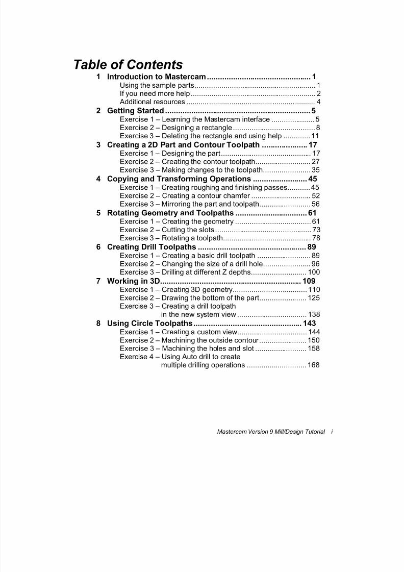
Table of Contents1 Introduction to Mastercam................................................ 1
Using the sample parts........................................................... 1 If you need more help............................................................. 2 Additional resources ............................................................... 4
2 Getting Started ...................................................................5 Exercise 1 – Learning the Mastercam interface ..................... 5 Exercise 2 – Designing a rectangle........................................ 8 Exercise 3 – Deleting the rectangle and using help .............11
3 Creating a 2D Part and Contour Toolpath ..................... 17 Exercise 1 – Designing the part............................................ 17 Exercise 2 – Creating the contour toolpath........................... 27 Exercise 3 – Making changes to the toolpath....................... 35
4 Copying and Transforming Operations ......................... 45 Exercise 1 – Creating roughing and finishing passes...........45 Exercise 2 – Creating a contour chamfer ............................. 52 Exercise 3 – Mirroring the part and toolpath.........................56
5 Rotating Geometry and Toolpaths ................................. 61 Exercise 1 – Creating the geometry ..................................... 61 Exercise 2 – Cutting the slots............................................... 73 Exercise 3 – Rotating a toolpath........................................... 78
6 Creating Drill Toolpaths .................................................. 89 Exercise 1 – Creating a basic drill toolpath .......................... 89 Exercise 2 – Changing the size of a drill hole....................... 96 Exercise 3 – Drilling at different Z depths........................... 100
7 Working in 3D................................................................. 109 Exercise 1 – Creating 3D geometry.................................... 110 Exercise 2 – Drawing the bottom of the part....................... 125
Exercise 3 – Creating a drill toolpath
in the new system view .................................. 138 8 Using Circle Toolpaths.................................................. 143
Exercise 1 – Creating a custom view.................................. 144 Exercise 2 – Machining the outside contour....................... 150 Exercise 3 – Machining the holes and slot ......................... 158 Exercise 4 – Using Auto drill to create
multiple drilling operations .............................168
7/18/2019 V9 Mill-Design Tutorial (metric).pdf
http://slidepdf.com/reader/full/v9-mill-design-tutorial-metricpdf 10/453
ii Mastercam Version 9 Mill/Design Tutorial
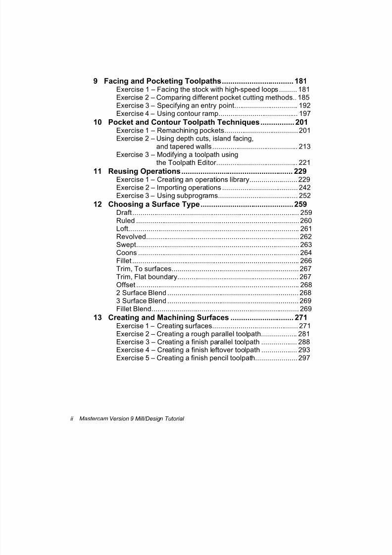
9 Facing and Pocketing Toolpaths.................................. 181 Exercise 1 – Facing the stock with high-speed loops......... 181 Exercise 2 – Comparing different pocket cutting methods..185 Exercise 3 – Specifying an entry point................................ 192 Exercise 4 – Using contour ramp........................................ 197
10 Pocket and Contour Toolpath Techniques................ 201 Exercise 1 – Remachining pockets..................................... 201 Exercise 2 – Using depth cuts, island facing,
and tapered walls........................................... 213 Exercise 3 – Modifying a toolpath using
the Toolpath Editor......................................... 221 11 Reusing Operations..................................................... 229
Exercise 1 – Creating an operations library........................ 229 Exercise 2 – Importing operations ...................................... 242 Exercise 3 – Using subprograms........................................ 252
12 Choosing a Surface Type............................................ 259 Draft.................................................................................... 259 Ruled ..................................................................................260 Loft...................................................................................... 261 Revolved.............................................................................262 Swept.................................................................................. 263 Coons ................................................................................. 264 Fillet .................................................................................... 266 Trim, To surfaces................................................................ 267 Trim, Flat boundary............................................................. 267 Offset .................................................................................. 268 2 Surface Blend .................................................................. 268 3 Surface Blend .................................................................. 269 Fillet Blend.......................................................................... 269
13 Creating and Machining Surfaces .............................. 271 Exercise 1 – Creating surfaces........................................... 271 Exercise 2 – Creating a rough parallel toolpath.................. 281 Exercise 3 – Creating a finish parallel toolpath .................. 288 Exercise 4 – Creating a finish leftover toolpath .................. 293 Exercise 5 – Creating a finish pencil toolpath.....................297
7/18/2019 V9 Mill-Design Tutorial (metric).pdf
http://slidepdf.com/reader/full/v9-mill-design-tutorial-metricpdf 11/453
Mastercam Version 9 Mill/Design Tutorial iii
14 Surface Roughing........................................................ 303 Exercise 1 – Creating a rough pocket toolpath................... 303 Exercise 2 – Creating a rough plunge toolpath................... 308 Exercise 3 – Creating a restmill toolpath ............................ 317 Exercise 4 – Creating a high speed pocket toolpath .......... 329
15 Surface Finishing......................................................... 337 Exercise 1 – Using finish steep and shallow toolpaths....... 337 Exercise 2 – Creating a finish radial toolpath ..................... 345 Exercise 3 – Creating a finish project toolpath ................... 348 Exercise 4 – Creating a finish contour toolpath .................. 351 Exercise 5 – Creating a contour shallow toolpath............... 357 Exercise 6 – Creating a finish scallop toolpath................... 361 Exercise 7 – Creating a finish flowline toolpath .................. 365
16 Creating Multiaxis Toolpaths...................................... 371 Exercise 1 – Creating a curve 5-axis toolpath .................... 371 Exercise 2 – Creating a swarf 5-axis toolpath .................... 379
17 Machining Solids ......................................................... 391 Exercise 1 – Machining the pocket ..................................... 392 Exercise 2 – Drilling the holes ............................................ 401
18 Glossary ....................................................................... 413 19 Mastercam Shortcut Keys...........................................441

7/18/2019 V9 Mill-Design Tutorial (metric).pdf
http://slidepdf.com/reader/full/v9-mill-design-tutorial-metricpdf 12/453
7/18/2019 V9 Mill-Design Tutorial (metric).pdf
http://slidepdf.com/reader/full/v9-mill-design-tutorial-metricpdf 13/453
Introduction to Mastercam
Mastercam Version 9 Mill/Design Tutorial 1
1 Introduction to Mastercam
Welcome to Mastercam Version 9. Mastercam Design is a full-featured
modeling application that combines 2D and 3D wireframe geometry andsurfacing abilities with powerful editing and transformation tools.
Mastercam Mill builds on Mastercam Design by letting you create and
manage a wide variety of machining operations. Mastercam uses a feature
called associativity to link machining operations to the geometry so that
toolpaths can be automatically regenerated when part geometry changes.
To help you learn Mastercam, this tutorial and extensive online help
accompany the product.
Use this tutorial as a self-training aid to orient yourself to the
Mastercam program and interface. After completing the tutorial, you
will have a good introduction to accomplishing common drafting andmilling operations with Mastercam. However, the tutorial does not try
to cover every Mastercam feature.
Use the online help as a reference for specific "How to…" or "What's
this…" questions, like "How do I machine an open pocket," "What's a
Coons surface," or "How do I create a new tool definition?" This
tutorial shows you how to use online help.
Using the sample parts
The sample parts for all the exercises in this tutorial are located in the
C:\Mcam9\Tutorials\Mill Tutorial\Metric folder. The sample parts areread-only, so you do not accidentally write over them. You should create a
separate working folder where you can save your own parts as you
complete the tutorial.
7/18/2019 V9 Mill-Design Tutorial (metric).pdf
http://slidepdf.com/reader/full/v9-mill-design-tutorial-metricpdf 14/453
Chapter 1
2 Mastercam Version 9 Mill/Design Tutorial
Note: The parts for the exercises in this tutorial were created using metric
units of measurement. When you open one of the tutorial parts, if you are
using a configuration file based on different units of measure, Mastercam
will automatically switch configuration files to match the units in the
current file. For example, if you are working with the metric configuration
file for Mastercam Mill (Mill9m.cfg) and you open an inch part, the
system switches to the inch configuration file (Mill9.cfg).
If you need more help
Online help
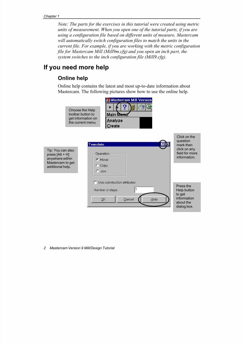
Online help contains the latest and most up-to-date information about
Mastercam. The following pictures show how to use the online help.
Press theHelp buttonto getinformationabout thedialog box.
Click on thequestionmark thenclick on anyfield for moreinformation.
Tip: You can alsopress [Alt + H]anywhere withinMastercam to getadditional help.
Choose the Helptoolbar button toget information onthe current menu.

7/18/2019 V9 Mill-Design Tutorial (metric).pdf
http://slidepdf.com/reader/full/v9-mill-design-tutorial-metricpdf 15/453
Introduction to Mastercam
Mastercam Version 9 Mill/Design Tutorial 3
Dealers
If you have a question about Mastercam and have not been able to locate
the answer in this tutorial or the online help, contact your local Mastercam
dealer.
Technical support
If your dealer is unavailable, you can call CNC Software Support ServicesMonday through Friday, 8:00 a.m.–6:00 p.m., USA Eastern Standard
Time.
When calling CNC Software, Inc. for technical support, please follow
these guidelines:
Be sure you have already tried to contact your Mastercam dealer.
Be ready to describe the problem in detail. Write down what
happened, particularly if you cannot call immediately after the
problem occurs.
Be in front of your computer when you call.
If possible, try to duplicate the problem before calling. Our Support
Services technician may require you to duplicate the problem while
you are on the phone.
When you call, have ready a complete description of your hardware,
including your operating system (OS), central processing unit (CPU),
mouse, and memory.
You can also leave a message for CNC Support Services twenty-four
hours a day, seven days a week via our e-mail or web site addresses or the
BBS. A member of our technical support staff will return your e-mail or
call you on the next business day.
Keep the following information on hand in case you need to reach us:
7/18/2019 V9 Mill-Design Tutorial (metric).pdf
http://slidepdf.com/reader/full/v9-mill-design-tutorial-metricpdf 16/453
Chapter 1
4 Mastercam Version 9 Mill/Design Tutorial
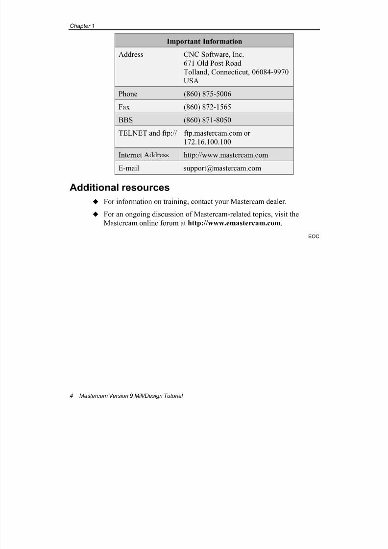
Important Information
Address CNC Software, Inc.
671 Old Post Road
Tolland, Connecticut, 06084-9970
USA
Phone (860) 875-5006Fax (860) 872-1565
BBS (860) 871-8050
TELNET and ftp:// ftp.mastercam.com or
172.16.100.100
Internet Address http://www.mastercam.com
E-mail [email protected]
Additional resources For information on training, contact your Mastercam dealer.
For an ongoing discussion of Mastercam-related topics, visit the
Mastercam online forum at http://www.emastercam.com.
EOC
7/18/2019 V9 Mill-Design Tutorial (metric).pdf
http://slidepdf.com/reader/full/v9-mill-design-tutorial-metricpdf 17/453
Getting Started
Mastercam Version 9 Mill/Design Tutorial 5
2 Getting Started
This chapter introduces you to the Mastercam interface. You will learn
about some major Mastercam features, create and delete some simplegeometry, learn how to access the online reference material, and save
files.
Exercise 1 – Learning the Mastercam interface
This exercise shows you how to navigate through Mastercam. You will
learn the following skills:
Starting Mastercam
Learning about the different areas on the screen
Creating a point
Displaying the construction origin and coordinate axes
Starting Mastercam
1. Double-click the appropriate Mastercam icon on your Windows®
desktop:
for Mastercam Design
for Mastercam Mill
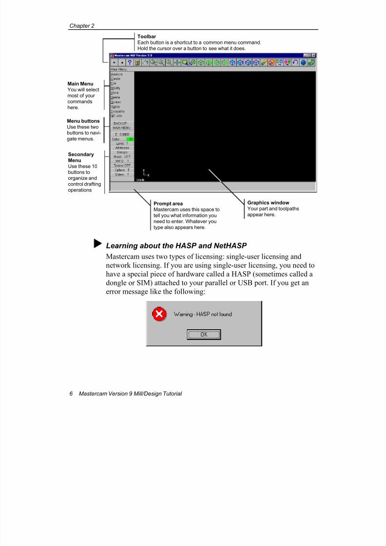
The following picture shows you some of the main features of theMastercam workspace.
7/18/2019 V9 Mill-Design Tutorial (metric).pdf
http://slidepdf.com/reader/full/v9-mill-design-tutorial-metricpdf 18/453
Chapter 2
6 Mastercam Version 9 Mill/Design Tutorial
Learning about the HASP and NetHASP
Mastercam uses two types of licensing: single-user licensing and
network licensing. If you are using single-user licensing, you need to
have a special piece of hardware called a HASP (sometimes called a
dongle or SIM) attached to your parallel or USB port. If you get an
error message like the following:
Toolbar
Each button is a shortcut to a common menu command.
Hold the cursor over a button to see what it does.
Main MenuYou will select
most of yourcommands
here.
Menu buttons
Use these twobuttons to navi-
gate menus.
Secondary
Menu
Use these 10buttons to
organize and
control drafting
operations
Prompt areaMastercam uses this space to
tell you what information you
need to enter. Whatever you
type also appears here.
Graphics window
Your part and toolpaths
appear here.
7/18/2019 V9 Mill-Design Tutorial (metric).pdf
http://slidepdf.com/reader/full/v9-mill-design-tutorial-metricpdf 19/453
Getting Started
Mastercam Version 9 Mill/Design Tutorial 7
this component is either missing or not configured properly. Refer to
your installation instructions (included in a separate document) or
contact your dealer for assistance.
If you are using network licensing, then a NetHASP must be installed
on a computer on your network. If you see any of the following
messages, see your network administrator:
Error checking out a Mill license. No licenses havebeen purchased for this product.
Active NetHASP server not found.
All available licenses are in use.
For more information on NetHASP installation, see Mastercam
Network Licensing.doc in your main Mastercam folder.
Creating a point
The Main Menu is where you will start most tasks in Mastercam.
1. Choose Main Menu, Create, Point, Position.
Notice that the prompt area at the bottom left of the screendisplays the message Create point: specify a point .
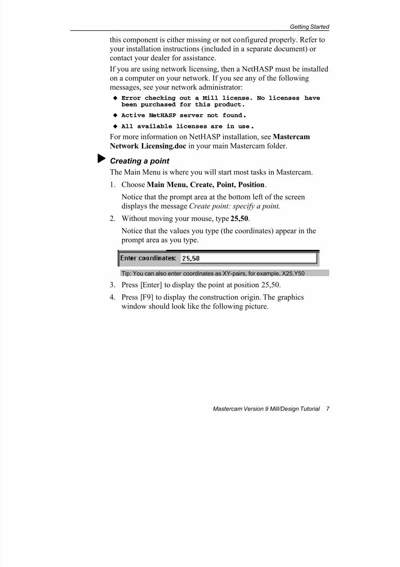
2. Without moving your mouse, type 25,50.
Notice that the values you type (the coordinates) appear in the
prompt area as you type.
Tip: You can also enter coordinates as XY-pairs, for example, X25,Y50
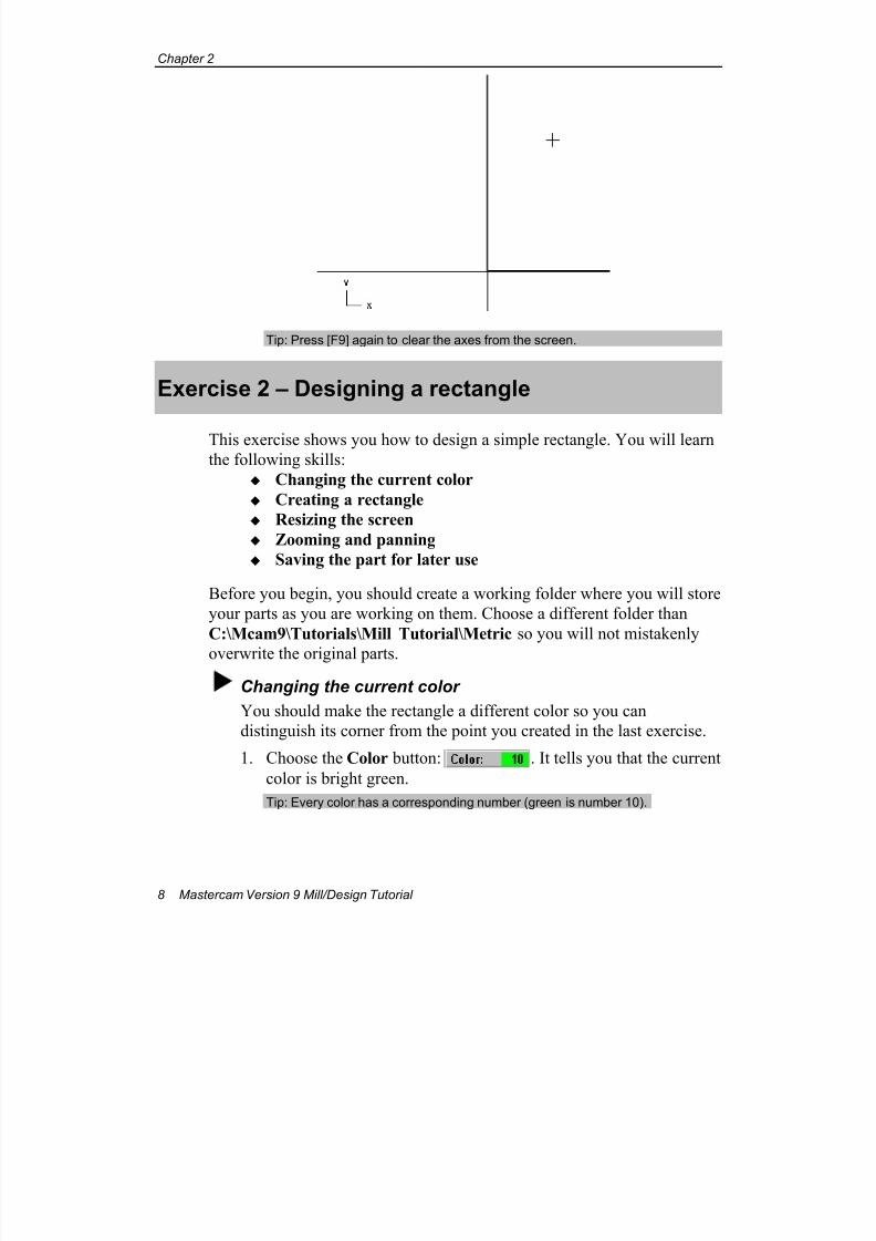
3. Press [Enter] to display the point at position 25,50.
4. Press [F9] to display the construction origin. The graphicswindow should look like the following picture.
7/18/2019 V9 Mill-Design Tutorial (metric).pdf
http://slidepdf.com/reader/full/v9-mill-design-tutorial-metricpdf 20/453
Chapter 2
8 Mastercam Version 9 Mill/Design Tutorial
Tip: Press [F9] again to clear the axes from the screen.
Exercise 2 – Designing a rectangle
This exercise shows you how to design a simple rectangle. You will learnthe following skills:
Changing the current color
Creating a rectangle
Resizing the screen
Zooming and panning
Saving the part for later use
Before you begin, you should create a working folder where you will store
your parts as you are working on them. Choose a different folder than
C:\Mcam9\Tutorials\Mill Tutorial\Metric so you will not mistakenly
overwrite the original parts.
Changing the current color
You should make the rectangle a different color so you can
distinguish its corner from the point you created in the last exercise.
1. Choose the Color button: . It tells you that the current
color is bright green.
Tip: Every color has a corresponding number (green is number 10).
7/18/2019 V9 Mill-Design Tutorial (metric).pdf
http://slidepdf.com/reader/full/v9-mill-design-tutorial-metricpdf 21/453
Getting Started
Mastercam Version 9 Mill/Design Tutorial 9
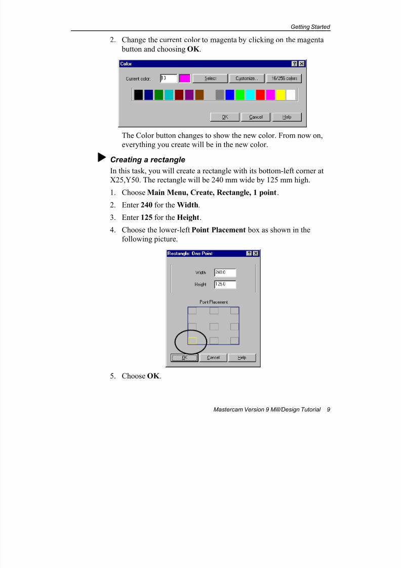
2. Change the current color to magenta by clicking on the magenta
button and choosing OK .
The Color button changes to show the new color. From now on,
everything you create will be in the new color.
Creating a rectangle
In this task, you will create a rectangle with its bottom-left corner at
X25,Y50. The rectangle will be 240 mm wide by 125 mm high.
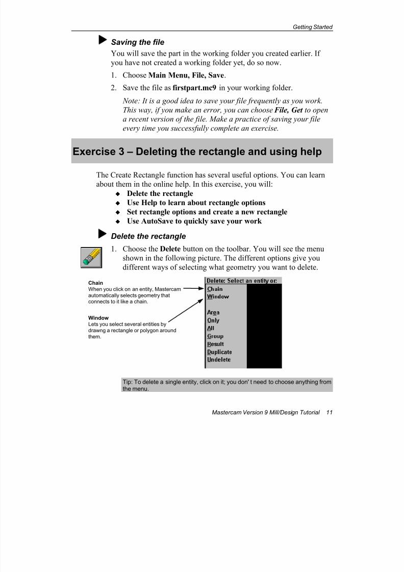
1. Choose Main Menu, Create, Rectangle, 1 point.
2. Enter 240 for the Width.
3. Enter 125 for the Height.
4. Choose the lower-left Point Placement box as shown in the
following picture.
5. Choose OK .

7/18/2019 V9 Mill-Design Tutorial (metric).pdf
http://slidepdf.com/reader/full/v9-mill-design-tutorial-metricpdf 22/453
Chapter 2
10 Mastercam Version 9 Mill/Design Tutorial
6. Drag the cursor near the point you created earlier until you see a
small white square appear around the point. Notice that the cursor
"snaps" into position when you come near the point; this is
Mastercam's AutoCursor feature.
7. Click the mouse button. This positions the rectangle so that its
lower left corner is at the coordinates 25,50. Notice that the
rectangle function is still active; every time you click the mouse,you will create another rectangle.
8. Press [Esc] to exit the rectangle function.
Note: If you accidentally create more than one rectangle, choose
the Undo button from the toolbar. It will undo the most recent
rectangle.
9. Choose the Screen–Fit button on the toolbar so you can see
the entire rectangle.
10. You can pan the screen by pressing the arrow keys (Left, Right,
Up, and Down). Press the arrow keys to try it.11. Press the [Page Up] and [Page Down] keys to zoom in or out.
Each key press zooms in or out by 5%.
Your part should look like the following picture.
7/18/2019 V9 Mill-Design Tutorial (metric).pdf
http://slidepdf.com/reader/full/v9-mill-design-tutorial-metricpdf 23/453
Getting Started
Mastercam Version 9 Mill/Design Tutorial 11
Saving the file
You will save the part in the working folder you created earlier. If
you have not created a working folder yet, do so now.
1. Choose Main Menu, File, Save.
2. Save the file as firstpart.mc9 in your working folder.
Note: It is a good idea to save your file frequently as you work.This way, if you make an error, you can choose File, Get to open
a recent version of the file. Make a practice of saving your file
every time you successfully complete an exercise.
Exercise 3 – Deleting the rectangle and using help
The Create Rectangle function has several useful options. You can learn
about them in the online help. In this exercise, you will:
Delete the rectangle
Use Help to learn about rectangle options Set rectangle options and create a new rectangle
Use AutoSave to quickly save your work
Delete the rectangle
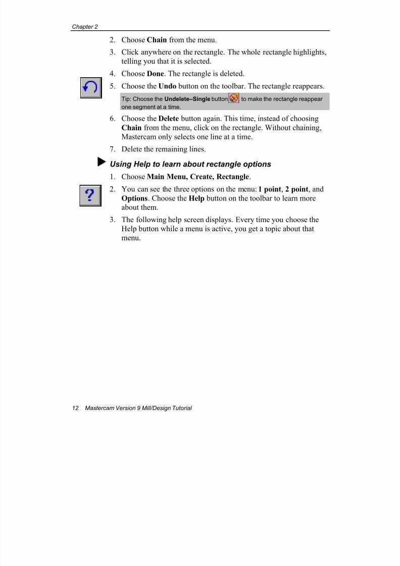
1. Choose the Delete button on the toolbar. You will see the menu
shown in the following picture. The different options give you
different ways of selecting what geometry you want to delete.
Tip: To delete a single entity, click on it; you don' t need to choose anything fromthe menu.
Chain
When you click on an entity, Mastercam
automatically selects geometry that
connects to it like a chain.
Window
Lets you select several entities by
drawng a rectangle or polygon around
them.
7/18/2019 V9 Mill-Design Tutorial (metric).pdf
http://slidepdf.com/reader/full/v9-mill-design-tutorial-metricpdf 24/453
Chapter 2
12 Mastercam Version 9 Mill/Design Tutorial
2. Choose Chain from the menu.
3. Click anywhere on the rectangle. The whole rectangle highlights,
telling you that it is selected.
4. Choose Done. The rectangle is deleted.
5. Choose the Undo button on the toolbar. The rectangle reappears.
Tip: Choose the Undelete–Single button to make the rectangle reappearone segment at a time.
6. Choose the Delete button again. This time, instead of choosing
Chain from the menu, click on the rectangle. Without chaining,
Mastercam only selects one line at a time.
7. Delete the remaining lines.
Using Help to learn about rectangle options
1. Choose Main Menu, Create, Rectangle.
2. You can see the three options on the menu: 1 point, 2 point, and
Options. Choose the Help button on the toolbar to learn moreabout them.
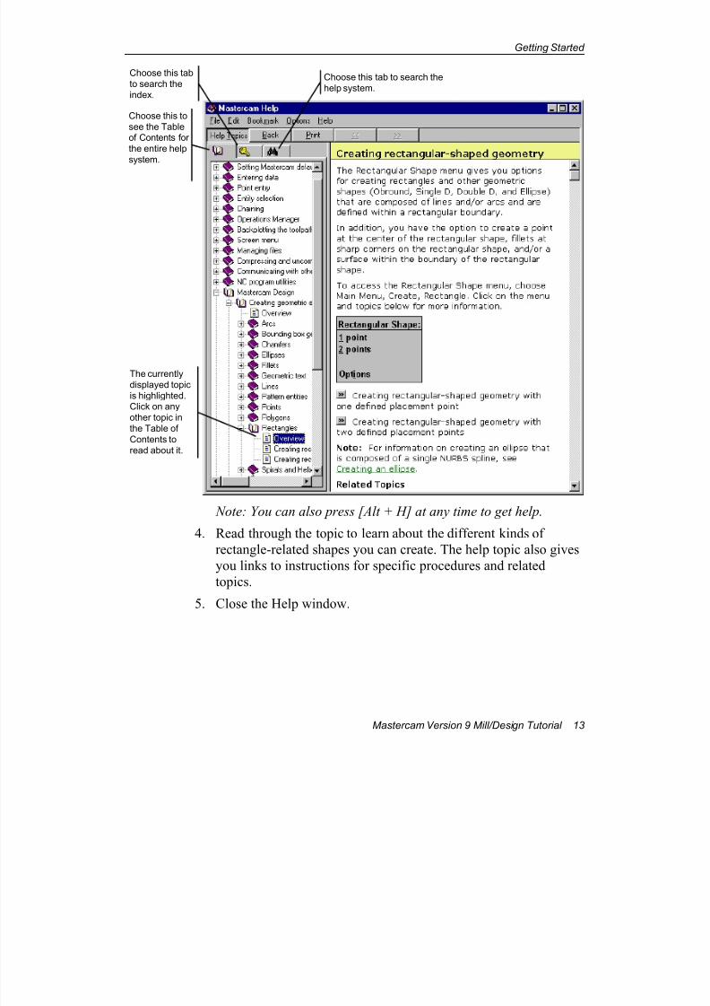
3. The following help screen displays. Every time you choose the
Help button while a menu is active, you get a topic about that
menu.
7/18/2019 V9 Mill-Design Tutorial (metric).pdf
http://slidepdf.com/reader/full/v9-mill-design-tutorial-metricpdf 25/453
Getting Started
Mastercam Version 9 Mill/Design Tutorial 13
Note: You can also press [Alt + H] at any time to get help.
4. Read through the topic to learn about the different kinds ofrectangle-related shapes you can create. The help topic also gives
you links to instructions for specific procedures and related
topics.
5. Close the Help window.
Choose this to
see the Tableof Contents for
the entire help
system.
Choose this tab
to search the
index.
Choose this tab to search the
help system.
The currently
displayed topic
is highlighted.Click on any
other topic in
the Table of
Contents to
read about it.
7/18/2019 V9 Mill-Design Tutorial (metric).pdf
http://slidepdf.com/reader/full/v9-mill-design-tutorial-metricpdf 26/453
Chapter 2
14 Mastercam Version 9 Mill/Design Tutorial
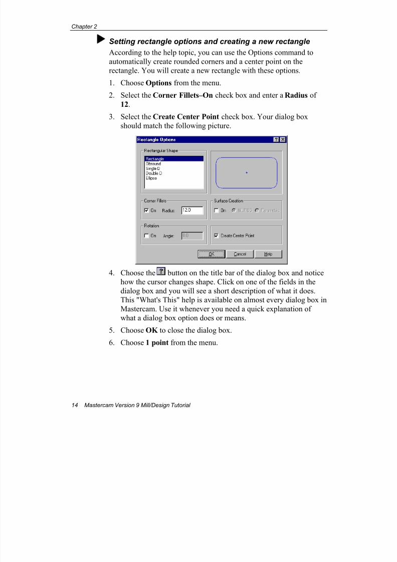
Setting rectangle options and creating a new rectangle
According to the help topic, you can use the Options command to
automatically create rounded corners and a center point on the
rectangle. You will create a new rectangle with these options.
1. Choose Options from the menu.
2. Select the Corner Fillets–On check box and enter a Radius of12.
3. Select the Create Center Point check box. Your dialog box
should match the following picture.
4. Choose the button on the title bar of the dialog box and notice
how the cursor changes shape. Click on one of the fields in the
dialog box and you will see a short description of what it does.
This "What's This" help is available on almost every dialog box in
Mastercam. Use it whenever you need a quick explanation of
what a dialog box option does or means.
5. Choose OK to close the dialog box.
6. Choose 1 point from the menu.
7/18/2019 V9 Mill-Design Tutorial (metric).pdf
http://slidepdf.com/reader/full/v9-mill-design-tutorial-metricpdf 27/453
Getting Started
Mastercam Version 9 Mill/Design Tutorial 15
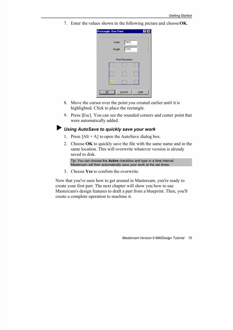
7. Enter the values shown in the following picture and choose OK .
8. Move the cursor over the point you created earlier until it is
highlighted. Click to place the rectangle.
9. Press [Esc]. You can see the rounded corners and center point thatwere automatically added.
Using AutoSave to quickly save your work
1. Press [Alt + A] to open the AutoSave dialog box.
2. Choose OK to quickly save the file with the same name and in the
same location. This will overwrite whatever version is already
saved to disk.
Tip: You can choose the Active checkbox and type in a time interval.Mastercam will then automatically save your work at the set times.
3. Choose Yes to confirm the overwrite.
Now that you've seen how to get around in Mastercam, you're ready to
create your first part. The next chapter will show you how to use
Mastercam's design features to draft a part from a blueprint. Then, you'll
create a complete operation to machine it.

7/18/2019 V9 Mill-Design Tutorial (metric).pdf
http://slidepdf.com/reader/full/v9-mill-design-tutorial-metricpdf 28/453
Chapter 2
16 Mastercam Version 9 Mill/Design Tutorial
7/18/2019 V9 Mill-Design Tutorial (metric).pdf
http://slidepdf.com/reader/full/v9-mill-design-tutorial-metricpdf 29/453
Creating a 2D Part and Contour Toolpath
Mastercam Version 9 Mill/Design Tutorial 17
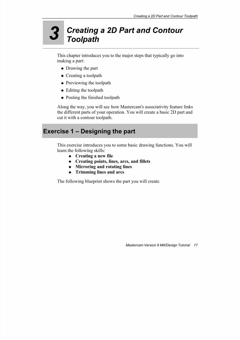
3 Creating a 2D Part and ContourToolpath
This chapter introduces you to the major steps that typically go into
making a part:
Drawing the part
Creating a toolpath
Previewing the toolpath
Editing the toolpath
Posting the finished toolpath
Along the way, you will see how Mastercam's associativity feature linksthe different parts of your operation. You will create a basic 2D part and
cut it with a contour toolpath.
Exercise 1 – Designing the part
This exercise introduces you to some basic drawing functions. You will
learn the following skills:
Creating a new file
Creating points, lines, arcs, and fillets
Mirroring and rotating lines
Trimming lines and arcs
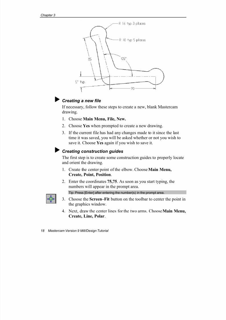
The following blueprint shows the part you will create.
7/18/2019 V9 Mill-Design Tutorial (metric).pdf
http://slidepdf.com/reader/full/v9-mill-design-tutorial-metricpdf 30/453
Chapter 3
18 Mastercam Version 9 Mill/Design Tutorial
Creating a new file
If necessary, follow these steps to create a new, blank Mastercam
drawing.
1. Choose Main Menu, File, New.
2. Choose Yes when prompted to create a new drawing.
3. If the current file has had any changes made to it since the lasttime it was saved, you will be asked whether or not you wish to
save it. Choose Yes again if you wish to save it.
Creating construction guides
The first step is to create some construction guides to properly locateand orient the drawing.
1. Create the center point of the elbow. Choose Main Menu,Create, Point, Position.
2. Enter the coordinates 75,75. As soon as you start typing, the
numbers will appear in the prompt area.
Tip: Press [Enter] after entering the number(s) in the prompt area.
3. Choose the Screen–Fit button on the toolbar to center the point inthe graphics window.
4. Next, draw the center lines for the two arms. Choose Main Menu,
Create, Line, Polar.
7/18/2019 V9 Mill-Design Tutorial (metric).pdf
http://slidepdf.com/reader/full/v9-mill-design-tutorial-metricpdf 31/453
Creating a 2D Part and Contour Toolpath
Mastercam Version 9 Mill/Design Tutorial 19
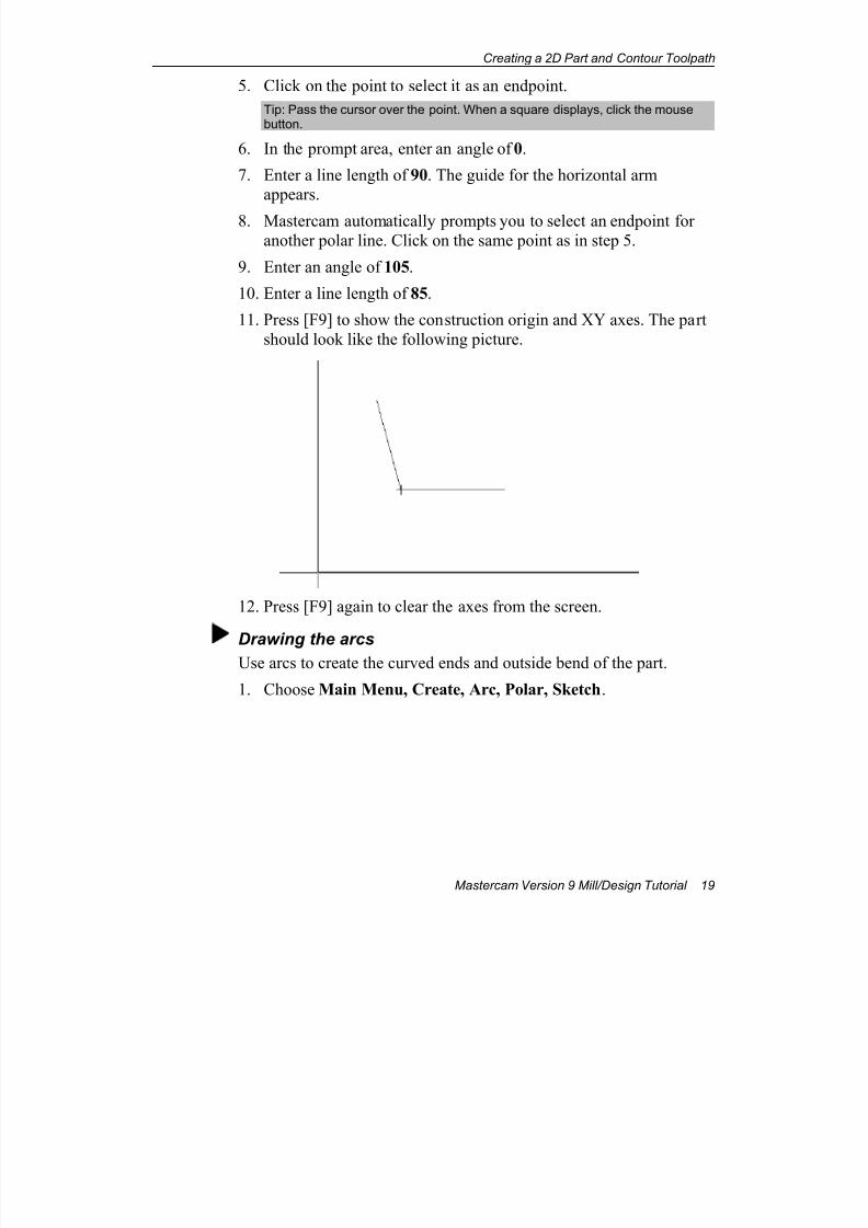
5. Click on the point to select it as an endpoint.
Tip: Pass the cursor over the point. When a square displays, click the mousebutton.
6. In the prompt area, enter an angle of 0.
7. Enter a line length of 90. The guide for the horizontal armappears.
8. Mastercam automatically prompts you to select an endpoint foranother polar line. Click on the same point as in step 5.
9. Enter an angle of 105.
10. Enter a line length of 85.
11. Press [F9] to show the construction origin and XY axes. The part
should look like the following picture.
12. Press [F9] again to clear the axes from the screen.
Drawing the arcsUse arcs to create the curved ends and outside bend of the part.
1. Choose Main Menu, Create, Arc, Polar, Sketch.
7/18/2019 V9 Mill-Design Tutorial (metric).pdf
http://slidepdf.com/reader/full/v9-mill-design-tutorial-metricpdf 32/453
Chapter 3
20 Mastercam Version 9 Mill/Design Tutorial
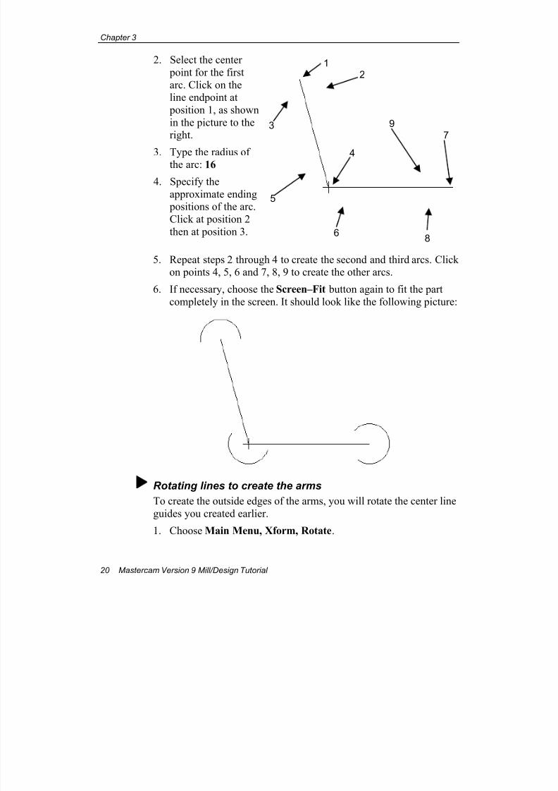
2. Select the center
point for the first
arc. Click on theline endpoint at
position 1, as shown
in the picture to the
right.3. Type the radius of
the arc: 16
4. Specify the
approximate ending positions of the arc.
Click at position 2
then at position 3.
5. Repeat steps 2 through 4 to create the second and third arcs. Click
on points 4, 5, 6 and 7, 8, 9 to create the other arcs.6. If necessary, choose the Screen–Fit button again to fit the part
completely in the screen. It should look like the following picture:
Rotating lines to create the arms
To create the outside edges of the arms, you will rotate the center line
guides you created earlier.
1. Choose Main Menu, Xform, Rotate.
3 9
8
7
6
5
4
21
7/18/2019 V9 Mill-Design Tutorial (metric).pdf
http://slidepdf.com/reader/full/v9-mill-design-tutorial-metricpdf 33/453
Creating a 2D Part and Contour Toolpath
Mastercam Version 9 Mill/Design Tutorial 21
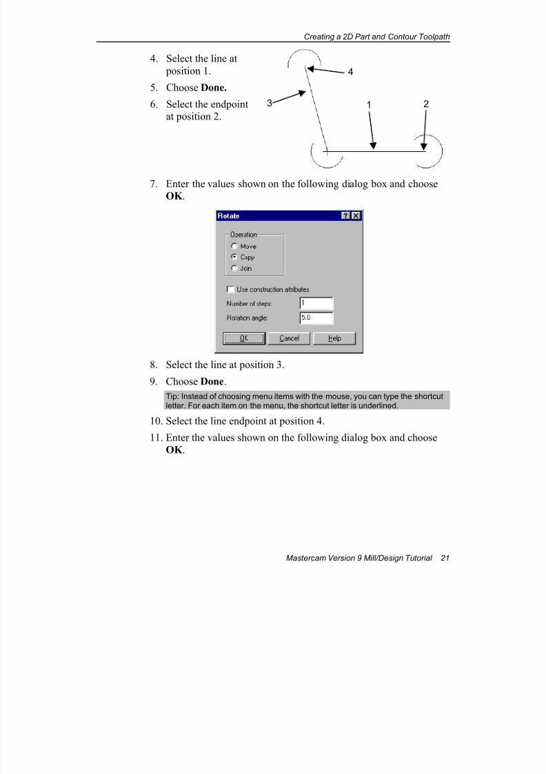
4. Select the line at
position 1.
5. Choose Done.
6. Select the endpointat position 2.
7. Enter the values shown on the following dialog box and chooseOK .
8. Select the line at position 3.
9. Choose Done.
Tip: Instead of choosing menu items with the mouse, you can type the shortcut
letter. For each item on the menu, the shortcut letter is underlined.
10. Select the line endpoint at position 4.
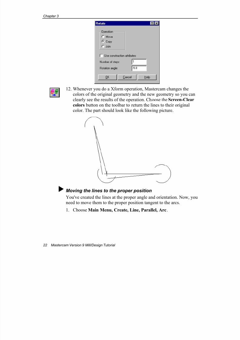
11. Enter the values shown on the following dialog box and choose
OK .
3
4
21
7/18/2019 V9 Mill-Design Tutorial (metric).pdf
http://slidepdf.com/reader/full/v9-mill-design-tutorial-metricpdf 34/453
Chapter 3
22 Mastercam Version 9 Mill/Design Tutorial
12. Whenever you do a Xform operation, Mastercam changes thecolors of the original geometry and the new geometry so you can
clearly see the results of the operation. Choose the Screen-Clear
colors button on the toolbar to return the lines to their originalcolor. The part should look like the following picture.
Moving the lines to the proper position
You've created the lines at the proper angle and orientation. Now, youneed to move them to the proper position tangent to the arcs.
1. Choose Main Menu, Create, Line, Parallel, Arc.
7/18/2019 V9 Mill-Design Tutorial (metric).pdf
http://slidepdf.com/reader/full/v9-mill-design-tutorial-metricpdf 35/453
Creating a 2D Part and Contour Toolpath
Mastercam Version 9 Mill/Design Tutorial 23
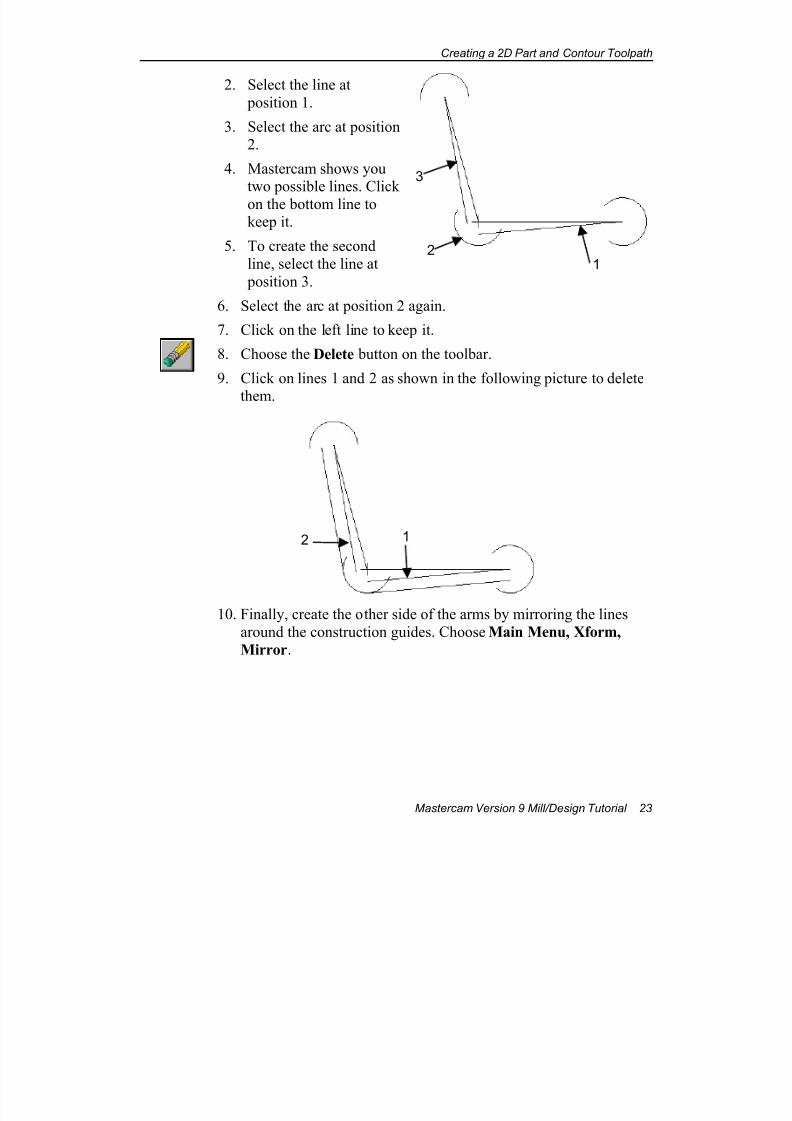
2. Select the line at
position 1.
3. Select the arc at position2.
4. Mastercam shows youtwo possible lines. Click
on the bottom line tokeep it.
5. To create the second
line, select the line at
position 3.
6. Select the arc at position 2 again.
7. Click on the left line to keep it.
8. Choose the Delete button on the toolbar.
9. Click on lines 1 and 2 as shown in the following picture to delete
them.
10. Finally, create the other side of the arms by mirroring the lines
around the construction guides. Choose Main Menu, Xform,
Mirror.
3
21
2 1
7/18/2019 V9 Mill-Design Tutorial (metric).pdf
http://slidepdf.com/reader/full/v9-mill-design-tutorial-metricpdf 36/453
Chapter 3
24 Mastercam Version 9 Mill/Design Tutorial
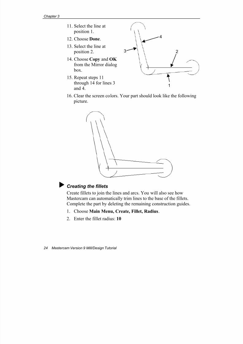
11. Select the line at
position 1.
12. Choose Done.
13. Select the line at position 2.
14. Choose Copy and OK from the Mirror dialog
box.
15. Repeat steps 11
through 14 for lines 3and 4.
16. Clear the screen colors. Your part should look like the following picture.
Creating the fillets
Create fillets to join the lines and arcs. You will also see how
Mastercam can automatically trim lines to the base of the fillets.Complete the part by deleting the remaining construction guides.
1. Choose Main Menu, Create, Fillet, Radius.
2. Enter the fillet radius: 10
4
2
1
3
7/18/2019 V9 Mill-Design Tutorial (metric).pdf
http://slidepdf.com/reader/full/v9-mill-design-tutorial-metricpdf 37/453
Creating a 2D Part and Contour Toolpath
Mastercam Version 9 Mill/Design Tutorial 25
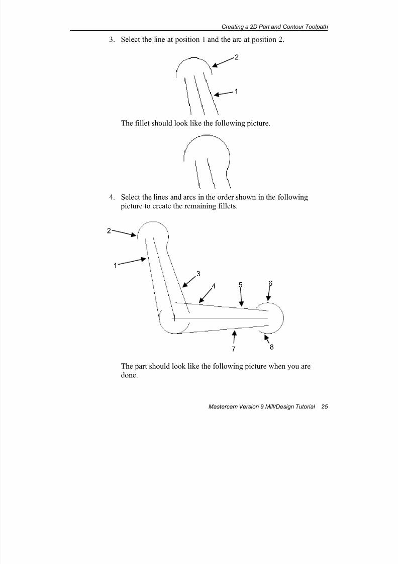
3. Select the line at position 1 and the arc at position 2.
The fillet should look like the following picture.
4. Select the lines and arcs in the order shown in the following picture to create the remaining fillets.
The part should look like the following picture when you aredone.
2
1
1
4
2
5
3
6
87
7/18/2019 V9 Mill-Design Tutorial (metric).pdf
http://slidepdf.com/reader/full/v9-mill-design-tutorial-metricpdf 38/453
Chapter 3
26 Mastercam Version 9 Mill/Design Tutorial
Tip: To turn off the automatic trim feature, choose Trim from the Fillet menu sothat it is set to N.
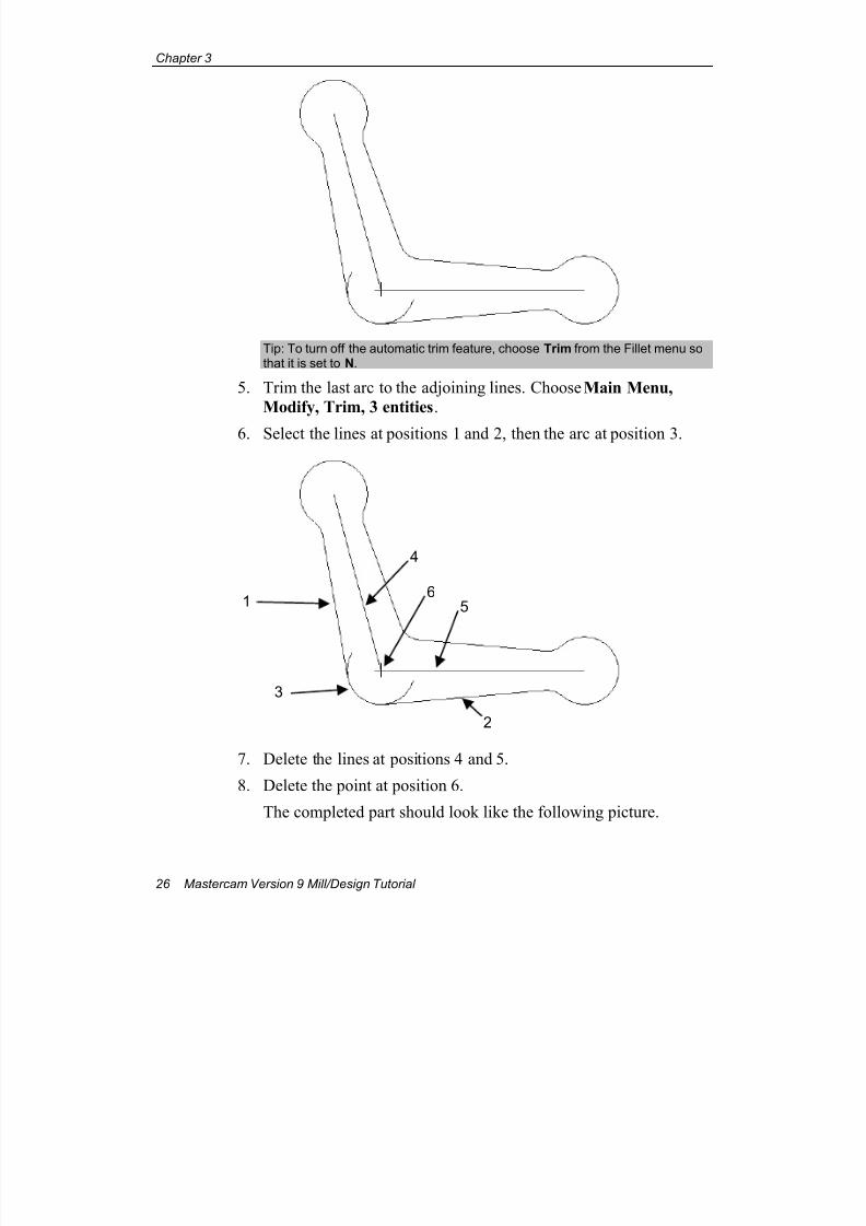
5. Trim the last arc to the adjoining lines. Choose Main Menu,
Modify, Trim, 3 entities.
6. Select the lines at positions 1 and 2, then the arc at position 3.
7. Delete the lines at positions 4 and 5.
8. Delete the point at position 6.
The completed part should look like the following picture.
1
2
3
6
4
5
7/18/2019 V9 Mill-Design Tutorial (metric).pdf
http://slidepdf.com/reader/full/v9-mill-design-tutorial-metricpdf 39/453
Creating a 2D Part and Contour Toolpath
Mastercam Version 9 Mill/Design Tutorial 27
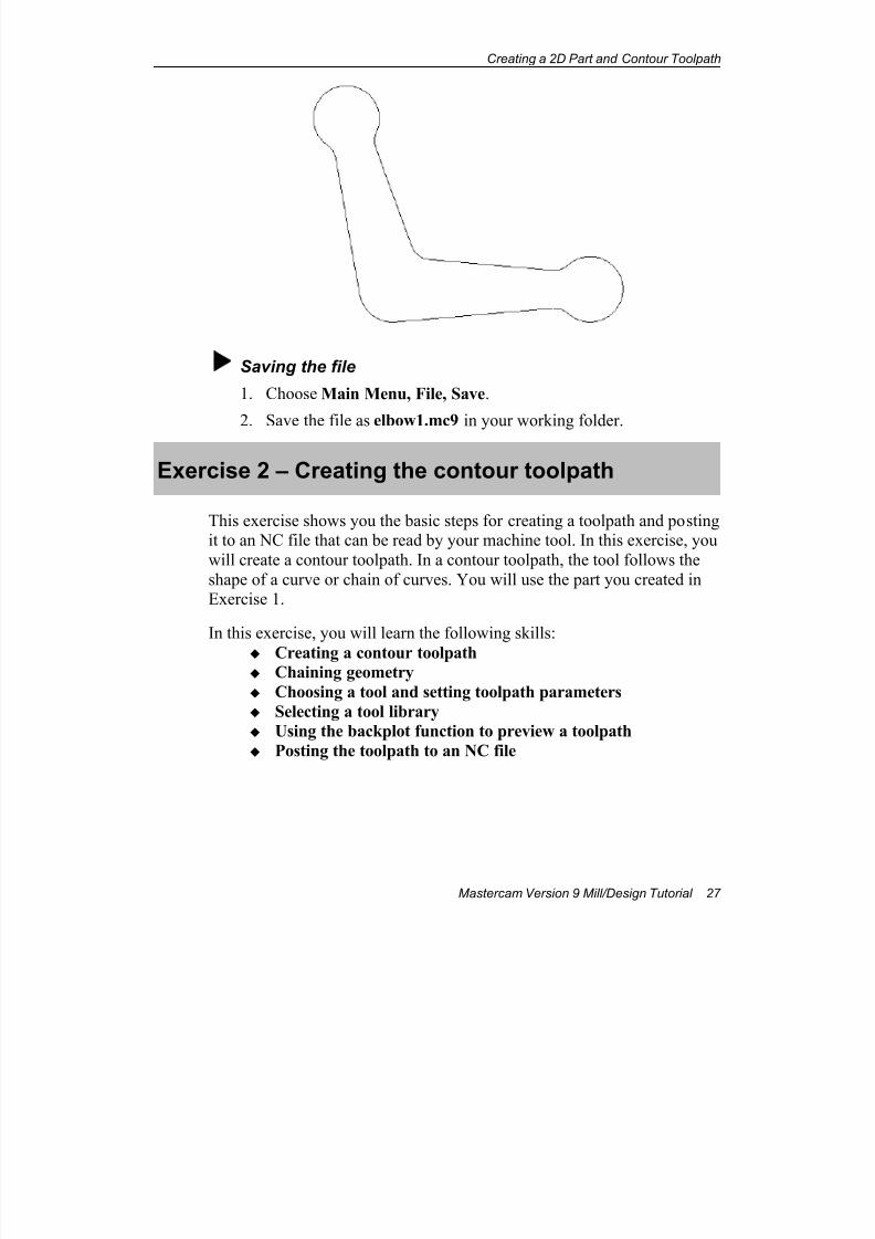
Saving the file
1. Choose Main Menu, File, Save.
2. Save the file as elbow1.mc9 in your working folder.
Exercise 2 – Creating the contour toolpath
This exercise shows you the basic steps for creating a toolpath and postingit to an NC file that can be read by your machine tool. In this exercise, you
will create a contour toolpath. In a contour toolpath, the tool follows the
shape of a curve or chain of curves. You will use the part you created inExercise 1.
In this exercise, you will learn the following skills:
Creating a contour toolpath Chaining geometry
Choosing a tool and setting toolpath parameters
Selecting a tool library
Using the backplot function to preview a toolpath
Posting the toolpath to an NC file
7/18/2019 V9 Mill-Design Tutorial (metric).pdf
http://slidepdf.com/reader/full/v9-mill-design-tutorial-metricpdf 40/453
Chapter 3
28 Mastercam Version 9 Mill/Design Tutorial
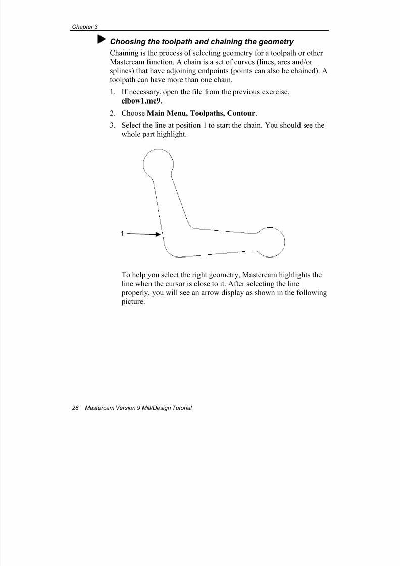
Choosing the toolpath and chaining the geometry
Chaining is the process of selecting geometry for a toolpath or other
Mastercam function. A chain is a set of curves (lines, arcs and/orsplines) that have adjoining endpoints (points can also be chained). A
toolpath can have more than one chain.
1. If necessary, open the file from the previous exercise,
elbow1.mc9.
2. Choose Main Menu, Toolpaths, Contour.
3. Select the line at position 1 to start the chain. You should see the
whole part highlight.
To help you select the right geometry, Mastercam highlights the
line when the cursor is close to it. After selecting the line properly, you will see an arrow display as shown in the following
picture.
1
7/18/2019 V9 Mill-Design Tutorial (metric).pdf
http://slidepdf.com/reader/full/v9-mill-design-tutorial-metricpdf 41/453
Creating a 2D Part and Contour Toolpath
Mastercam Version 9 Mill/Design Tutorial 29
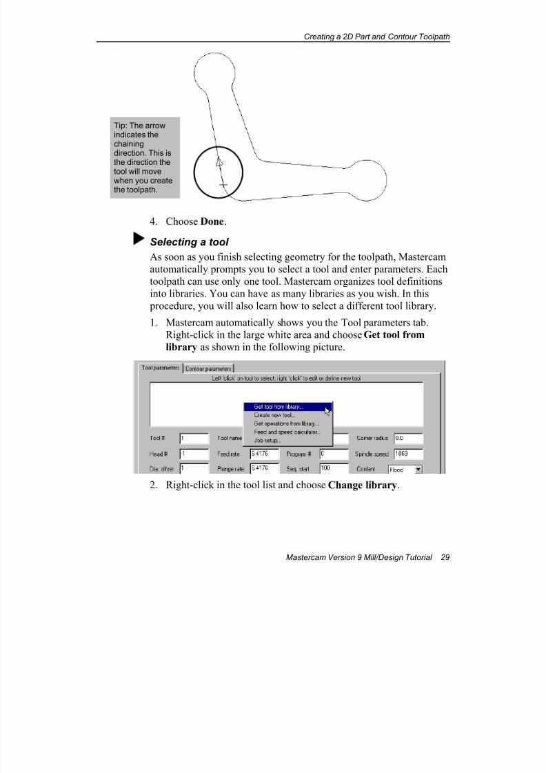
4. Choose Done.
Selecting a tool
As soon as you finish selecting geometry for the toolpath, Mastercam
automatically prompts you to select a tool and enter parameters. Eachtoolpath can use only one tool. Mastercam organizes tool definitions
into libraries. You can have as many libraries as you wish. In this
procedure, you will also learn how to select a different tool library.
1. Mastercam automatically shows you the Tool parameters tab.Right-click in the large white area and choose Get tool from
library as shown in the following picture.
2. Right-click in the tool list and choose Change library.
Tip: The arrow
indicates thechainingdirection. This isthe direction thetool will movewhen you createthe toolpath.
7/18/2019 V9 Mill-Design Tutorial (metric).pdf
http://slidepdf.com/reader/full/v9-mill-design-tutorial-metricpdf 42/453
Chapter 3
30 Mastercam Version 9 Mill/Design Tutorial
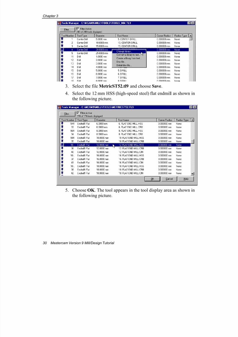
3. Select the file MetricST52.tl9 and choose Save.
4. Select the 12 mm HSS (high-speed steel) flat endmill as shown in
the following picture.
5. Choose OK . The tool appears in the tool display area as shown in
the following picture.
7/18/2019 V9 Mill-Design Tutorial (metric).pdf
http://slidepdf.com/reader/full/v9-mill-design-tutorial-metricpdf 43/453
Creating a 2D Part and Contour Toolpath
Mastercam Version 9 Mill/Design Tutorial 31
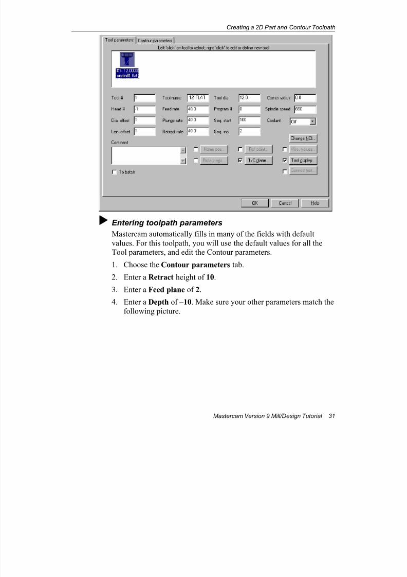
Entering toolpath parameters
Mastercam automatically fills in many of the fields with default
values. For this toolpath, you will use the default values for all theTool parameters, and edit the Contour parameters.
1. Choose the Contour parameters tab.
2. Enter a Retract height of 10.
3. Enter a Feed plane of 2.
4. Enter a Depth of –10. Make sure your other parameters match thefollowing picture.
7/18/2019 V9 Mill-Design Tutorial (metric).pdf
http://slidepdf.com/reader/full/v9-mill-design-tutorial-metricpdf 44/453
Chapter 3
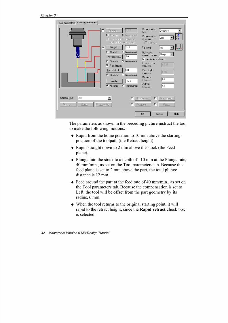
32 Mastercam Version 9 Mill/Design Tutorial
The parameters as shown in the preceding picture instruct the toolto make the following motions:
Rapid from the home position to 10 mm above the starting position of the toolpath (the Retract height).
Rapid straight down to 2 mm above the stock (the Feed
plane).
Plunge into the stock to a depth of –10 mm at the Plunge rate,
40 mm/min., as set on the Tool parameters tab. Because the
feed plane is set to 2 mm above the part, the total plungedistance is 12 mm.
Feed around the part at the feed rate of 40 mm/min., as set onthe Tool parameters tab. Because the compensation is set to
Left, the tool will be offset from the part geometry by its
radius, 6 mm.
When the tool returns to the original starting point, it will
rapid to the retract height, since the Rapid retract check box
is selected.
7/18/2019 V9 Mill-Design Tutorial (metric).pdf
http://slidepdf.com/reader/full/v9-mill-design-tutorial-metricpdf 45/453
Creating a 2D Part and Contour Toolpath
Mastercam Version 9 Mill/Design Tutorial 33
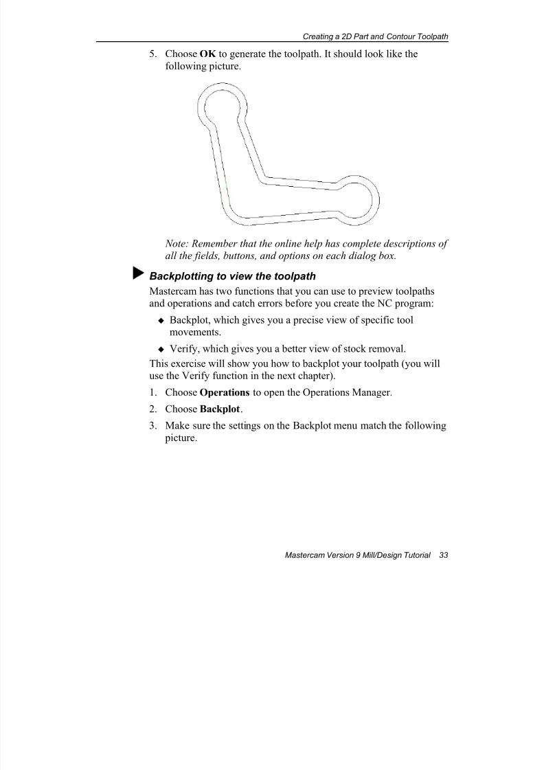
5. Choose OK to generate the toolpath. It should look like the
following picture.
Note: Remember that the online help has complete descriptions ofall the fields, buttons, and options on each dialog box.
Backplotting to view the toolpath
Mastercam has two functions that you can use to preview toolpathsand operations and catch errors before you create the NC program:
Backplot, which gives you a precise view of specific toolmovements.
Verify, which gives you a better view of stock removal.
This exercise will show you how to backplot your toolpath (you willuse the Verify function in the next chapter).
1. Choose Operations to open the Operations Manager.
2. Choose Backplot.
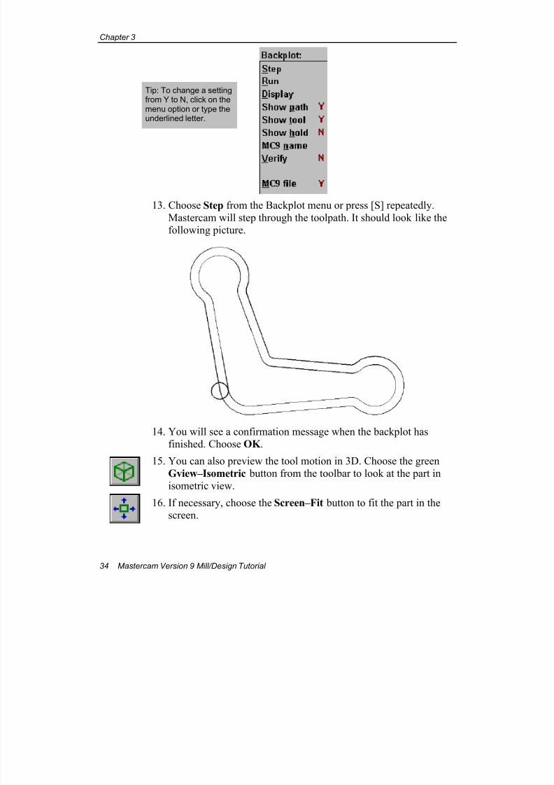
3. Make sure the settings on the Backplot menu match the following
picture.
7/18/2019 V9 Mill-Design Tutorial (metric).pdf
http://slidepdf.com/reader/full/v9-mill-design-tutorial-metricpdf 46/453
Chapter 3
34 Mastercam Version 9 Mill/Design Tutorial
13. Choose Step from the Backplot menu or press [S] repeatedly.
Mastercam will step through the toolpath. It should look like thefollowing picture.
14. You will see a confirmation message when the backplot hasfinished. Choose OK .
15. You can also preview the tool motion in 3D. Choose the green
Gview–Isometric button from the toolbar to look at the part in
isometric view.
16. If necessary, choose the Screen–Fit button to fit the part in thescreen.
Tip: To change a settingfrom Y to N, click on themenu option or type theunderlined letter.
7/18/2019 V9 Mill-Design Tutorial (metric).pdf
http://slidepdf.com/reader/full/v9-mill-design-tutorial-metricpdf 47/453
Creating a 2D Part and Contour Toolpath
Mastercam Version 9 Mill/Design Tutorial 35
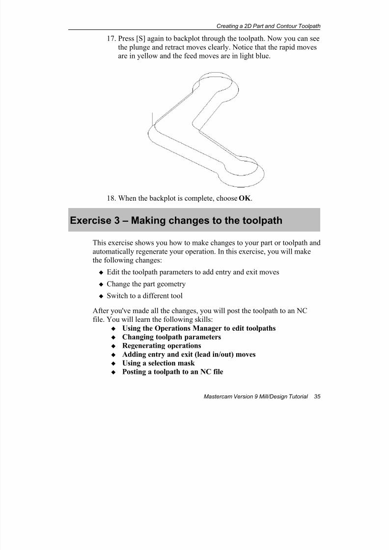
17. Press [S] again to backplot through the toolpath. Now you can see
the plunge and retract moves clearly. Notice that the rapid movesare in yellow and the feed moves are in light blue.
18. When the backplot is complete, choose OK .
Exercise 3 – Making changes to the toolpath
This exercise shows you how to make changes to your part or toolpath and
automatically regenerate your operation. In this exercise, you will makethe following changes:
Edit the toolpath parameters to add entry and exit moves
Change the part geometry
Switch to a different tool
After you've made all the changes, you will post the toolpath to an NC
file. You will learn the following skills:
Using the Operations Manager to edit toolpaths
Changing toolpath parameters
Regenerating operations
Adding entry and exit (lead in/out) moves
Using a selection mask
Posting a toolpath to an NC file
7/18/2019 V9 Mill-Design Tutorial (metric).pdf
http://slidepdf.com/reader/full/v9-mill-design-tutorial-metricpdf 48/453
Chapter 3
36 Mastercam Version 9 Mill/Design Tutorial
Adding lead in/out moves
For this part, you need to change how the tool enters the material.
Plunging directly into the part is not desirable because of the dwellmarks left behind at the tool entry spot. In this exercise, you add entry
and exit moves to the toolpath to eliminate the dwell marks.
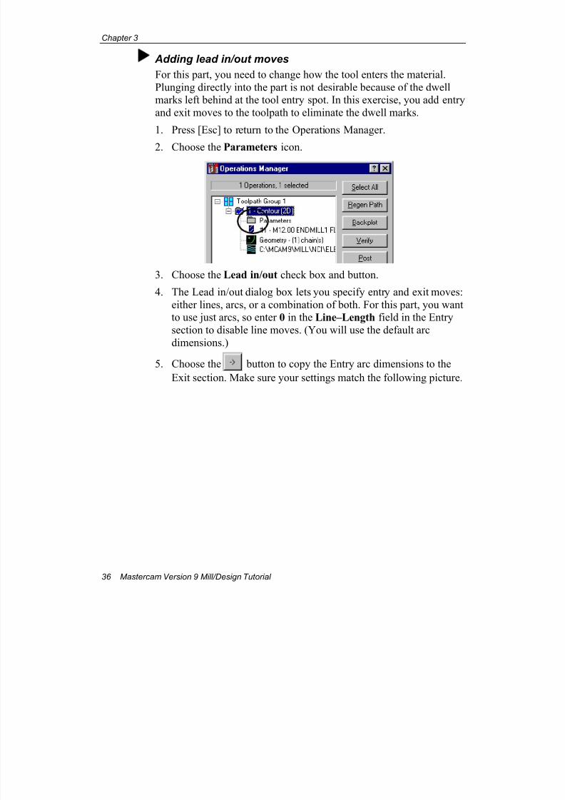
1. Press [Esc] to return to the Operations Manager.
2. Choose the Parameters icon.
3. Choose the Lead in/out check box and button.4. The Lead in/out dialog box lets you specify entry and exit moves:
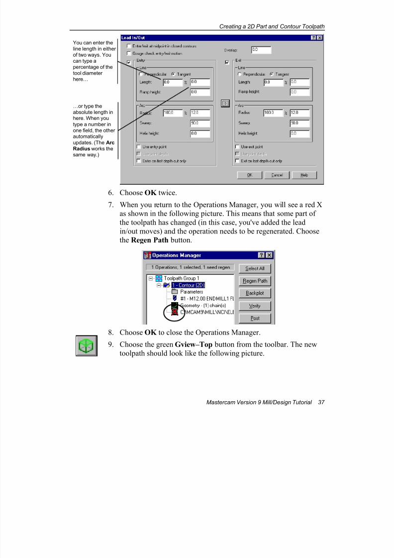
either lines, arcs, or a combination of both. For this part, you wantto use just arcs, so enter 0 in the Line–Length field in the Entry
section to disable line moves. (You will use the default arc
dimensions.)
5. Choose the button to copy the Entry arc dimensions to the
Exit section. Make sure your settings match the following picture.
7/18/2019 V9 Mill-Design Tutorial (metric).pdf
http://slidepdf.com/reader/full/v9-mill-design-tutorial-metricpdf 49/453
Creating a 2D Part and Contour Toolpath
Mastercam Version 9 Mill/Design Tutorial 37
6. Choose OK twice.7. When you return to the Operations Manager, you will see a red X
as shown in the following picture. This means that some part of
the toolpath has changed (in this case, you've added the lead
in/out moves) and the operation needs to be regenerated. Choosethe Regen Path button.
8. Choose OK to close the Operations Manager.
9. Choose the green Gview–Top button from the toolbar. The new
toolpath should look like the following picture.
You can enter the
line length in either
of two ways. You
can type a
percentage of the
tool diameter
here…
…or type the
absolute length inhere. When you
type a number in
one field, the otherautomatically
updates. (The Arc
Radius works thesame way.)

7/18/2019 V9 Mill-Design Tutorial (metric).pdf
http://slidepdf.com/reader/full/v9-mill-design-tutorial-metricpdf 50/453
Chapter 3
38 Mastercam Version 9 Mill/Design Tutorial
Changing the part geometry
In this procedure, you will make a design change to the part, changing
the 10 mm radius fillets to 6 mm fillets.
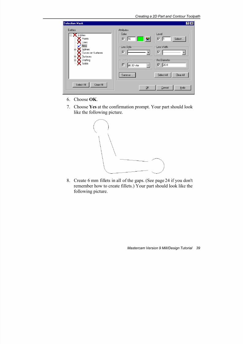
1. Choose Delete from the toolbar.2. Choose All, Mask .
3. The Selection Mask dialog box lets you describe which typesentities to delete. In the Entities list, choose Arcs.
4. Choose Same as.
5. Select any of the 10 mm fillets. When you return to the SelectionMask dialog box, you see that all of the fields are filled in with the
attributes of the 10 mm fillet. Mastercam will use this mask to
select all of the fillets and delete them.
7/18/2019 V9 Mill-Design Tutorial (metric).pdf
http://slidepdf.com/reader/full/v9-mill-design-tutorial-metricpdf 51/453
Creating a 2D Part and Contour Toolpath
Mastercam Version 9 Mill/Design Tutorial 39
6. Choose OK .
7. Choose Yes at the confirmation prompt. Your part should looklike the following picture.
8. Create 6 mm fillets in all of the gaps. (See page 24 if you don'tremember how to create fillets.) Your part should look like thefollowing picture.

7/18/2019 V9 Mill-Design Tutorial (metric).pdf
http://slidepdf.com/reader/full/v9-mill-design-tutorial-metricpdf 52/453
Chapter 3
40 Mastercam Version 9 Mill/Design Tutorial
Changing the tool
When you created the toolpath for this part, you used a 12 mm
endmill. Since the fillets are now smaller and the same radius as thetool, you will switch to a smaller tool so you can get smoother tool
motion around the fillets.
1. Press [Alt + O] to open the Operations Manager.
2. Choose the Parameters icon.
3. Choose the Tool parameters tab.
4. Right-click in the tool display area and choose Get tool from
library.
5. Select the 10 mm HSS flat endmill and choose OK .
6. Choose OK again to return to the Operations Manager.
7. Choose Regen Path to regenerate the toolpath with the new tool
and new geometry. The new toolpath should look like thefollowing picture.
7/18/2019 V9 Mill-Design Tutorial (metric).pdf
http://slidepdf.com/reader/full/v9-mill-design-tutorial-metricpdf 53/453
Creating a 2D Part and Contour Toolpath
Mastercam Version 9 Mill/Design Tutorial 41
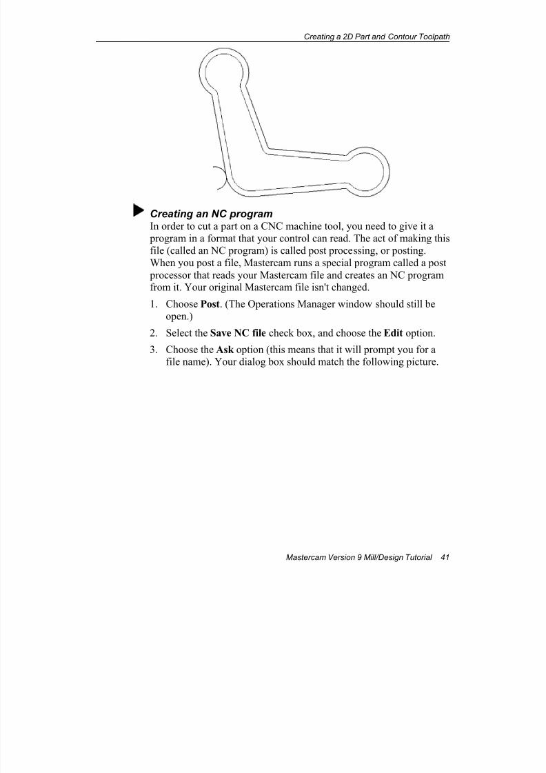
Creating an NC programIn order to cut a part on a CNC machine tool, you need to give it a
program in a format that your control can read. The act of making thisfile (called an NC program) is called post processing, or posting.
When you post a file, Mastercam runs a special program called a post
processor that reads your Mastercam file and creates an NC programfrom it. Your original Mastercam file isn't changed.
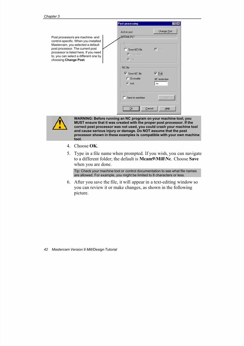
1. Choose Post. (The Operations Manager window should still be
open.)
2. Select the Save NC file check box, and choose the Edit option.
3. Choose the Ask option (this means that it will prompt you for afile name). Your dialog box should match the following picture.
7/18/2019 V9 Mill-Design Tutorial (metric).pdf
http://slidepdf.com/reader/full/v9-mill-design-tutorial-metricpdf 54/453
Chapter 3
42 Mastercam Version 9 Mill/Design Tutorial
WARNING: Before running an NC program on your machine tool, youMUST ensure that it was created with the proper post processor. If thecorrect post processor was not used, you could crash your machine tooland cause serious injury or damage. Do NOT assume that the postprocessor shown in these examples is compatible with your own machinetool.
4. Choose OK .
5. Type in a file name when prompted. If you wish, you can navigateto a different folder; the default is Mcam9\Mill\Nc. Choose Save
when you are done.
Tip: Check your machine tool or control documentation to see what file namesare allowed. For example, you might be limited to 8 characters or less.
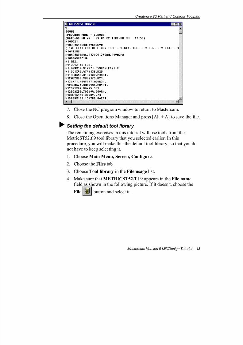
6. After you save the file, it will appear in a text-editing window soyou can review it or make changes, as shown in the following
picture.
Post processors are machine- and
control-specific. When you installed
Mastercam, you selected a default
post processor. The current post
processor is listed here. If you need
to, you can select a different one by
choosing Change Post.
7/18/2019 V9 Mill-Design Tutorial (metric).pdf
http://slidepdf.com/reader/full/v9-mill-design-tutorial-metricpdf 55/453
Creating a 2D Part and Contour Toolpath
Mastercam Version 9 Mill/Design Tutorial 43
7. Close the NC program window to return to Mastercam.
8. Close the Operations Manager and press [Alt + A] to save the file.
Setting the default tool library
The remaining exercises in this tutorial will use tools from the
MetricST52.tl9 tool library that you selected earlier. In this
procedure, you will make this the default tool library, so that you donot have to keep selecting it.
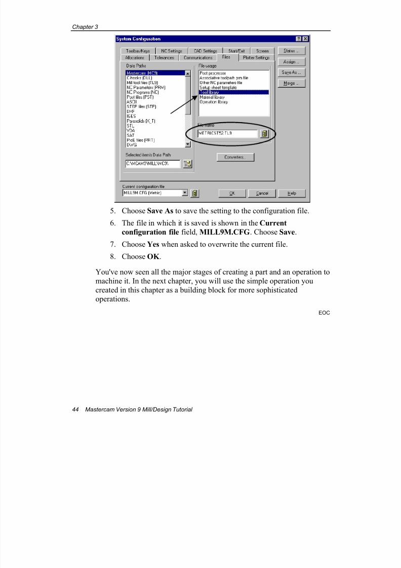
1. Choose Main Menu, Screen, Configure.
2. Choose the Files tab.
3. Choose Tool library in the File usage list.
4. Make sure that METRICST52.TL9 appears in the File name field as shown in the following picture. If it doesn't, choose the
File button and select it.
7/18/2019 V9 Mill-Design Tutorial (metric).pdf
http://slidepdf.com/reader/full/v9-mill-design-tutorial-metricpdf 56/453
Chapter 3
44 Mastercam Version 9 Mill/Design Tutorial
5. Choose Save As to save the setting to the configuration file.
6. The file in which it is saved is shown in the Current
configuration file field, MILL9M.CFG. Choose Save.
7. Choose Yes when asked to overwrite the current file.
8. Choose OK .
You've now seen all the major stages of creating a part and an operation to
machine it. In the next chapter, you will use the simple operation you
created in this chapter as a building block for more sophisticated
operations.
EOC
7/18/2019 V9 Mill-Design Tutorial (metric).pdf
http://slidepdf.com/reader/full/v9-mill-design-tutorial-metricpdf 57/453
Copying and Transforming Operations
Mastercam Version 9 Mill/Design Tutorial 45
4 Copying and TransformingOperations
This chapter shows you how to use the simple toolpath you created in the
previous chapter as a building block for more sophisticated operations.You will create the following new operations:
Finishing and multi-pass roughing operations
A chamfering operation
A mirrored copy of the operation
The part used in this chapter is the same one that you saved at the end of
Chapter 3. If you did not complete Chapter 3, use the file new elbow-
mm.mc9, in the folder C:\Mcam9\Tutorials\Mill Tutorial\Metric.
Tip: When opening this file, select the Restore entire NCI on file get option.
Exercise 1 – Creating roughing and finishingpasses
The 2D contour toolpath you created in the previous chapter only has a
single cutting pass. You decide that it takes off too much stock for a single
pass, so you decide to rough out the part in multiple passes with a larger
tool. You will complete the part with a separate finishing operation. In this
exercise, you will use the following skills:
Copying operations Creating multiple passes
Creating finishing operations
Changing tools and feed rates
Copying operations
To create the separate operations for roughing and finishing with the
minimum number of steps, you will copy the current 2D contour
operation and then edit the parameters for each copy.
7/18/2019 V9 Mill-Design Tutorial (metric).pdf
http://slidepdf.com/reader/full/v9-mill-design-tutorial-metricpdf 58/453
Chapter 4
46 Mastercam Version 9 Mill/Design Tutorial
1. If necessary, open the part file you saved at the end of Chapter 3.
If you did not complete Chapter 3, choose File, Get from the
menu, and open the file new elbow-mm.mc9 from the folder
C:\Mcam9\Tutorials\Mill Tutorial\Metric.
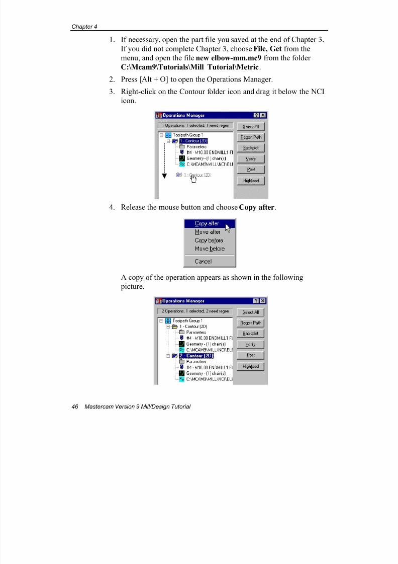
2. Press [Alt + O] to open the Operations Manager.
3. Right-click on the Contour folder icon and drag it below the NCI
icon.
4. Release the mouse button and choose Copy after.
A copy of the operation appears as shown in the following
picture.
7/18/2019 V9 Mill-Design Tutorial (metric).pdf
http://slidepdf.com/reader/full/v9-mill-design-tutorial-metricpdf 59/453
Copying and Transforming Operations
Mastercam Version 9 Mill/Design Tutorial 47
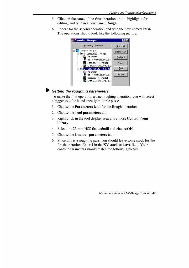
5. Click on the name of the first operation until it highlights for
editing, and type in a new name: Rough
6. Repeat for the second operation and type the new name: Finish.
The operations should look like the following picture.
Setting the roughing parameters
To make the first operation a true roughing operation, you will select
a bigger tool for it and specify multiple passes.
1. Choose the Parameters icon for the Rough operation.
2. Choose the Tool parameters tab.
3. Right-click in the tool display area and choose Get tool from
library.
4. Select the 25 mm HSS flat endmill and choose OK .
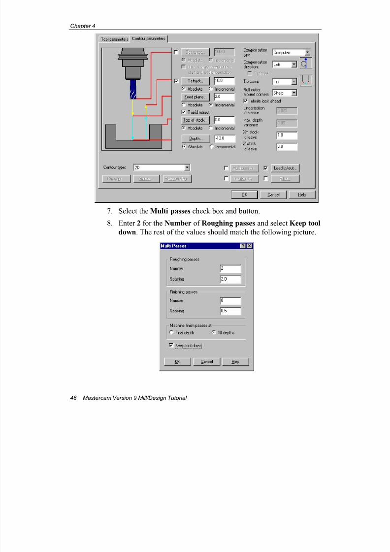
5. Choose the Contour parameters tab.
6. Since this is a roughing pass, you should leave some stock for thefinish operation. Enter 1 in the XY stock to leave field. Your
contour parameters should match the following picture.
7/18/2019 V9 Mill-Design Tutorial (metric).pdf
http://slidepdf.com/reader/full/v9-mill-design-tutorial-metricpdf 60/453
Chapter 4
48 Mastercam Version 9 Mill/Design Tutorial
7. Select the Multi passes check box and button.
8. Enter 2 for the Number of Roughing passes and select Keep tool
down. The rest of the values should match the following picture.
7/18/2019 V9 Mill-Design Tutorial (metric).pdf
http://slidepdf.com/reader/full/v9-mill-design-tutorial-metricpdf 61/453
Copying and Transforming Operations
Mastercam Version 9 Mill/Design Tutorial 49
9. Choose OK .
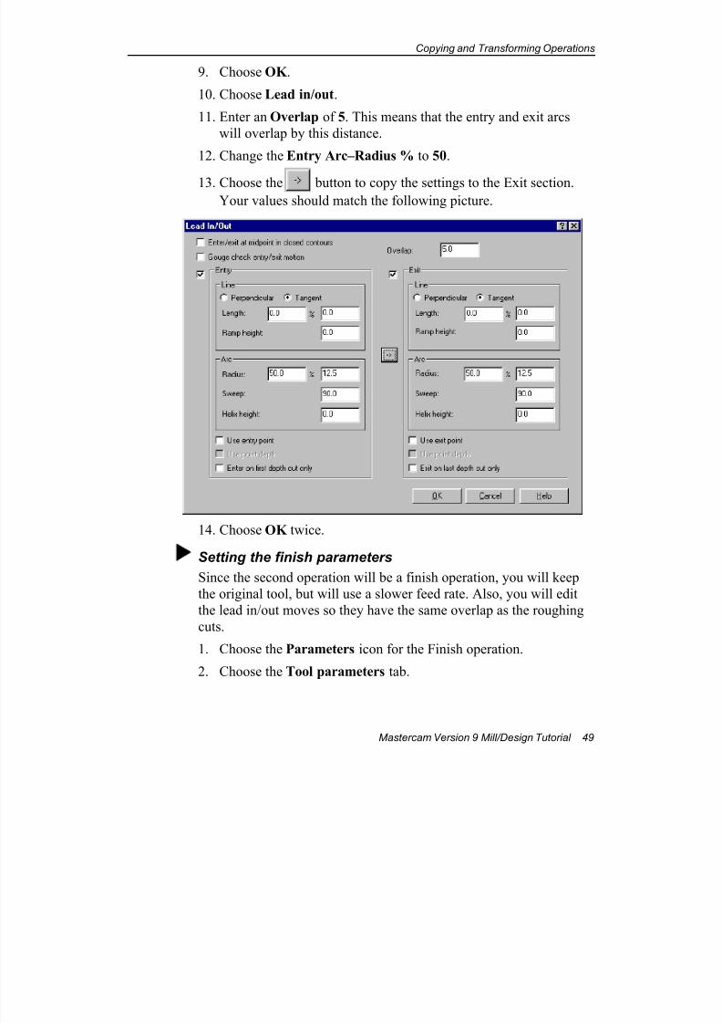
10. Choose Lead in/out.
11. Enter an Overlap of 5. This means that the entry and exit arcs
will overlap by this distance.
12. Change the Entry Arc–Radius % to 50.
13. Choose the button to copy the settings to the Exit section.Your values should match the following picture.
14. Choose OK twice.
Setting the finish parameters
Since the second operation will be a finish operation, you will keep
the original tool, but will use a slower feed rate. Also, you will edit
the lead in/out moves so they have the same overlap as the roughing
cuts.
1. Choose the Parameters icon for the Finish operation.
2. Choose the Tool parameters tab.
7/18/2019 V9 Mill-Design Tutorial (metric).pdf
http://slidepdf.com/reader/full/v9-mill-design-tutorial-metricpdf 62/453
Chapter 4
50 Mastercam Version 9 Mill/Design Tutorial
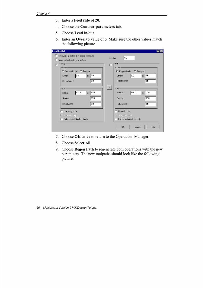
3. Enter a Feed rate of 20.
4. Choose the Contour parameters tab.
5. Choose Lead in/out.
6. Enter an Overlap value of 5. Make sure the other values match
the following picture.
7. Choose OK twice to return to the Operations Manager.
8. Choose Select All.
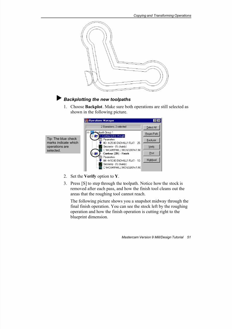
9. Choose Regen Path to regenerate both operations with the new
parameters. The new toolpaths should look like the following
picture.
7/18/2019 V9 Mill-Design Tutorial (metric).pdf
http://slidepdf.com/reader/full/v9-mill-design-tutorial-metricpdf 63/453
Copying and Transforming Operations
Mastercam Version 9 Mill/Design Tutorial 51
Backplotting the new toolpaths
1. Choose Backplot. Make sure both operations are still selected as
shown in the following picture.
2. Set the Verify option to Y.
3. Press [S] to step through the toolpath. Notice how the stock is
removed after each pass, and how the finish tool cleans out the
areas that the roughing tool cannot reach.
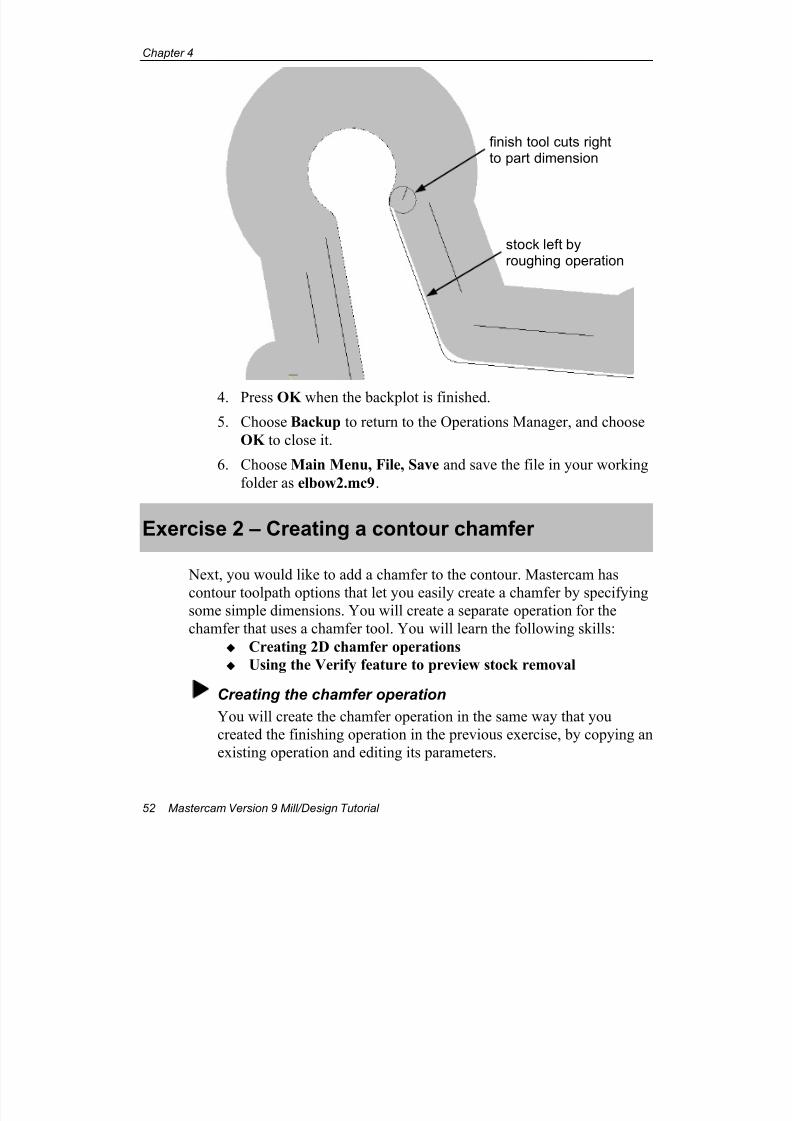
The following picture shows you a snapshot midway through the
final finish operation. You can see the stock left by the roughing
operation and how the finish operation is cutting right to the
blueprint dimension.
Tip: The blue checkmarks indicate whichoperations areselected.
7/18/2019 V9 Mill-Design Tutorial (metric).pdf
http://slidepdf.com/reader/full/v9-mill-design-tutorial-metricpdf 64/453
Chapter 4
52 Mastercam Version 9 Mill/Design Tutorial
4. Press OK when the backplot is finished.
5. Choose Backup to return to the Operations Manager, and choose
OK to close it.
6. Choose Main Menu, File, Save and save the file in your working
folder as elbow2.mc9.
Exercise 2 – Creating a contour chamfer
Next, you would like to add a chamfer to the contour. Mastercam has
contour toolpath options that let you easily create a chamfer by specifyingsome simple dimensions. You will create a separate operation for the
chamfer that uses a chamfer tool. You will learn the following skills:
Creating 2D chamfer operations
Using the Verify feature to preview stock removal
Creating the chamfer operation
You will create the chamfer operation in the same way that you
created the finishing operation in the previous exercise, by copying an
existing operation and editing its parameters.
stock left byroughing operation
finish tool cuts rightto part dimension
7/18/2019 V9 Mill-Design Tutorial (metric).pdf
http://slidepdf.com/reader/full/v9-mill-design-tutorial-metricpdf 65/453
Copying and Transforming Operations
Mastercam Version 9 Mill/Design Tutorial 53
1. Press [Alt + O] to open the Operations Manager.
2. Make a copy of the Finish operation and name the copy Chamfer.
(See page 45 if you don't remember how to do this.)
3. Choose the Parameters icon for the new Chamfer operation.
4. Choose the Tool parameters tab.
5. Select the 10 mm HSS chamfer mill from the tool library.6. Choose the Contour parameters tab.
7. In the Contour type drop-down list, select 2D chamfer.
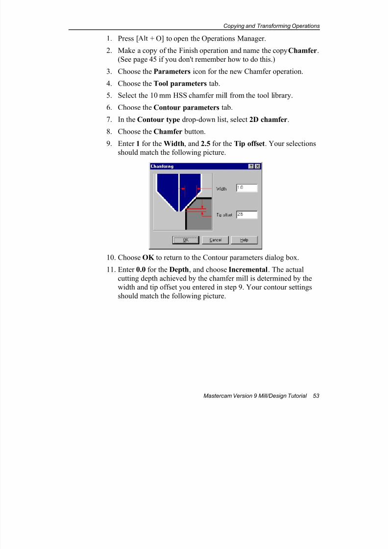
8. Choose the Chamfer button.
9. Enter 1 for the Width, and 2.5 for the Tip offset. Your selections
should match the following picture.
10. Choose OK to return to the Contour parameters dialog box.
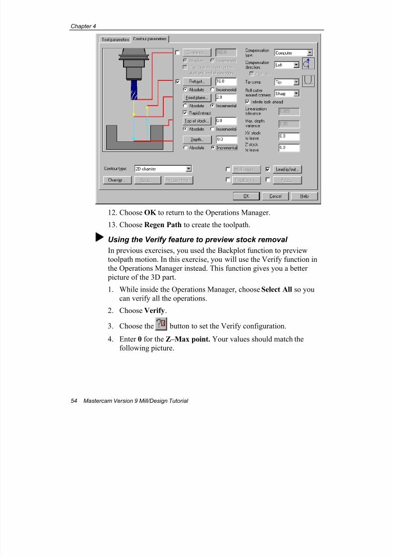
11. Enter 0.0 for the Depth, and choose Incremental. The actual
cutting depth achieved by the chamfer mill is determined by the
width and tip offset you entered in step 9. Your contour settingsshould match the following picture.
7/18/2019 V9 Mill-Design Tutorial (metric).pdf
http://slidepdf.com/reader/full/v9-mill-design-tutorial-metricpdf 66/453
Chapter 4
54 Mastercam Version 9 Mill/Design Tutorial
12. Choose OK to return to the Operations Manager.
13. Choose Regen Path to create the toolpath.
Using the Verify feature to preview stock removal
In previous exercises, you used the Backplot function to preview
toolpath motion. In this exercise, you will use the Verify function in
the Operations Manager instead. This function gives you a better
picture of the 3D part.
1. While inside the Operations Manager, choose Select All so youcan verify all the operations.
2. Choose Verify.
3. Choose the button to set the Verify configuration.
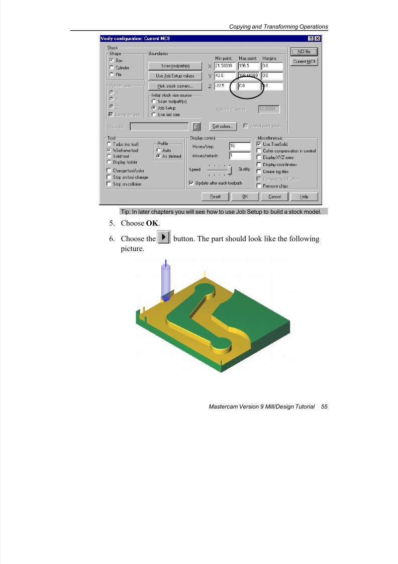
4. Enter 0 for the Z–Max point. Your values should match the
following picture.
7/18/2019 V9 Mill-Design Tutorial (metric).pdf
http://slidepdf.com/reader/full/v9-mill-design-tutorial-metricpdf 67/453
Copying and Transforming Operations
Mastercam Version 9 Mill/Design Tutorial 55
Tip: In later chapters you will see how to use Job Setup to build a stock model.
5. Choose OK .
6. Choose the button. The part should look like the following
picture.
7/18/2019 V9 Mill-Design Tutorial (metric).pdf
http://slidepdf.com/reader/full/v9-mill-design-tutorial-metricpdf 68/453
Chapter 4
56 Mastercam Version 9 Mill/Design Tutorial
7. Choose the button on the Verify toolbar to end the Verify
session and return to the Operations Manager.
8. Choose OK to close the Operations Manager.
Exercise 3 – Mirroring the part and toolpath
You are required to manufacture both left-hand and right-hand versions of
the part. You can do this by mirroring the part and toolpath. This lets you
maintain the original toolpath parameters and machining direction for all
the operations, ensuring that the duplicated part has the identical finish
and size as the original. In this exercise, you will learn the following
skills:
Creating mirror images of parts and toolpaths
Re-ordering operations in the Operations Manager for
greater machining efficiency
Mirroring the part1. Press the [Page Down] key several times to zoom out from the
part.
2. Right-click anywhere in the graphics window and choose
Dynamic Pan from the menu.
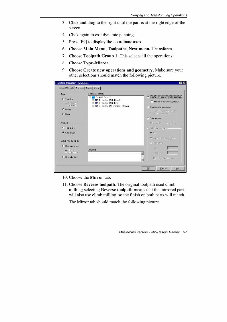
7/18/2019 V9 Mill-Design Tutorial (metric).pdf
http://slidepdf.com/reader/full/v9-mill-design-tutorial-metricpdf 69/453
Copying and Transforming Operations
Mastercam Version 9 Mill/Design Tutorial 57
3. Click and drag to the right until the part is at the right edge of the
screen.
4. Click again to exit dynamic panning.
5. Press [F9] to display the coordinate axes.
6. Choose Main Menu, Toolpaths, Next menu, Transform.
7. Choose Toolpath Group 1. This selects all the operations.8. Choose Type–Mirror.
9. Choose Create new operations and geometry. Make sure your
other selections should match the following picture.
10. Choose the Mirror tab.
11. Choose Reverse toolpath. The original toolpath used climb
milling; selecting Reverse toolpath means that the mirrored part
will also use climb milling, so the finish on both parts will match.
The Mirror tab should match the following picture.
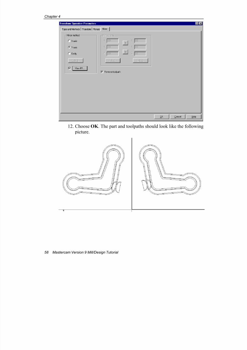
7/18/2019 V9 Mill-Design Tutorial (metric).pdf
http://slidepdf.com/reader/full/v9-mill-design-tutorial-metricpdf 70/453
Chapter 4
58 Mastercam Version 9 Mill/Design Tutorial
12. Choose OK . The part and toolpaths should look like the following
picture.
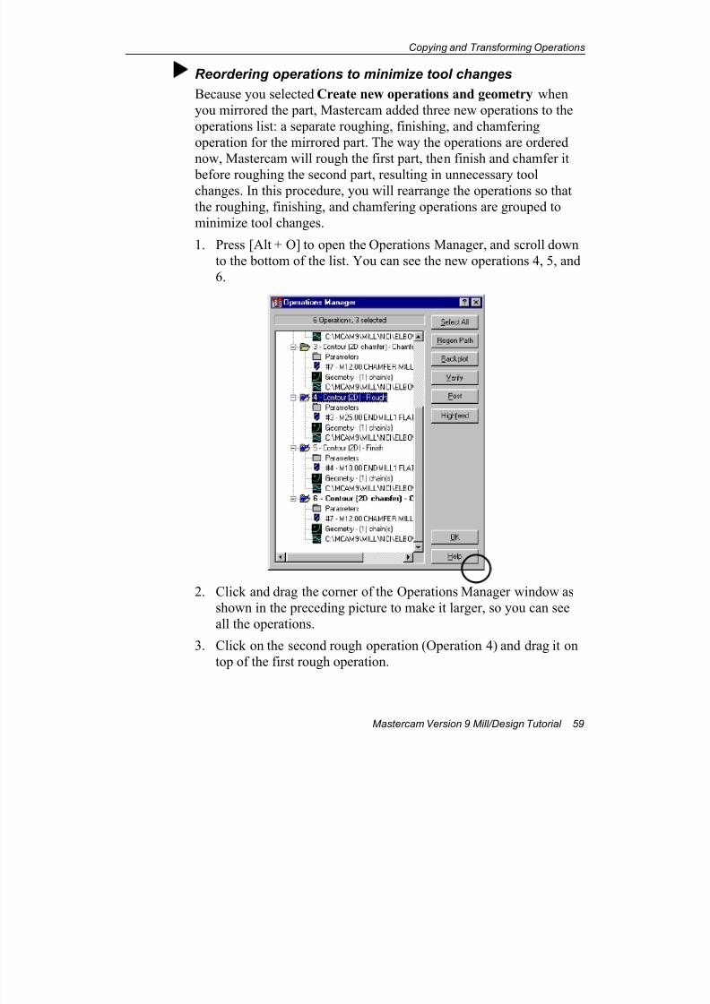
7/18/2019 V9 Mill-Design Tutorial (metric).pdf
http://slidepdf.com/reader/full/v9-mill-design-tutorial-metricpdf 71/453
Copying and Transforming Operations
Mastercam Version 9 Mill/Design Tutorial 59
Reordering operations to minimize tool changes
Because you selected Create new operations and geometry when
you mirrored the part, Mastercam added three new operations to the
operations list: a separate roughing, finishing, and chamfering
operation for the mirrored part. The way the operations are ordered
now, Mastercam will rough the first part, then finish and chamfer it
before roughing the second part, resulting in unnecessary toolchanges. In this procedure, you will rearrange the operations so that
the roughing, finishing, and chamfering operations are grouped to
minimize tool changes.
1. Press [Alt + O] to open the Operations Manager, and scroll down
to the bottom of the list. You can see the new operations 4, 5, and
6.
2. Click and drag the corner of the Operations Manager window as
shown in the preceding picture to make it larger, so you can see
all the operations.
3. Click on the second rough operation (Operation 4) and drag it on
top of the first rough operation.
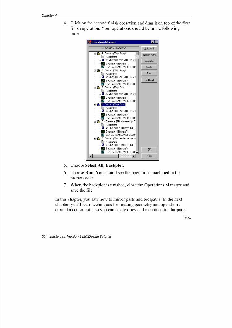
7/18/2019 V9 Mill-Design Tutorial (metric).pdf
http://slidepdf.com/reader/full/v9-mill-design-tutorial-metricpdf 72/453
Chapter 4
60 Mastercam Version 9 Mill/Design Tutorial
4. Click on the second finish operation and drag it on top of the first
finish operation. Your operations should be in the following
order.
5. Choose Select All, Backplot.
6. Choose Run. You should see the operations machined in the proper order.
7. When the backplot is finished, close the Operations Manager and
save the file.
In this chapter, you saw how to mirror parts and toolpaths. In the next
chapter, you'll learn techniques for rotating geometry and operations
around a center point so you can easily draw and machine circular parts.
EOC
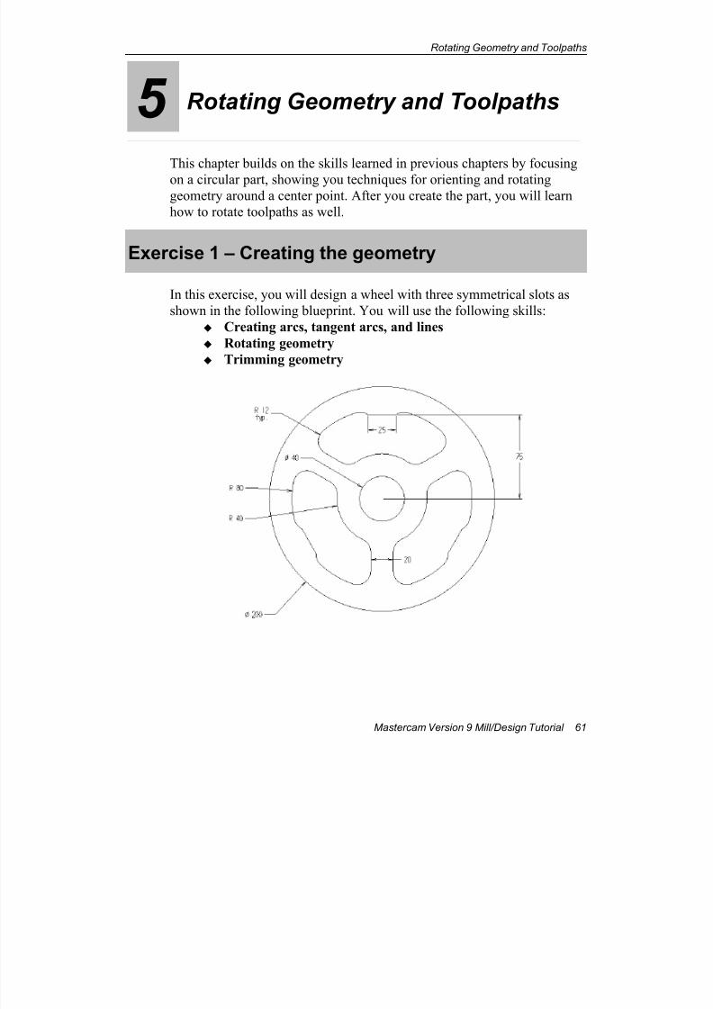
7/18/2019 V9 Mill-Design Tutorial (metric).pdf
http://slidepdf.com/reader/full/v9-mill-design-tutorial-metricpdf 73/453
Rotating Geometry and Toolpaths
Mastercam Version 9 Mill/Design Tutorial 61
5 Rotating Geometry and Toolpaths
This chapter builds on the skills learned in previous chapters by focusing
on a circular part, showing you techniques for orienting and rotatinggeometry around a center point. After you create the part, you will learn
how to rotate toolpaths as well.
Exercise 1 – Creating the geometry
In this exercise, you will design a wheel with three symmetrical slots as
shown in the following blueprint. You will use the following skills:
Creating arcs, tangent arcs, and lines
Rotating geometry
Trimming geometry
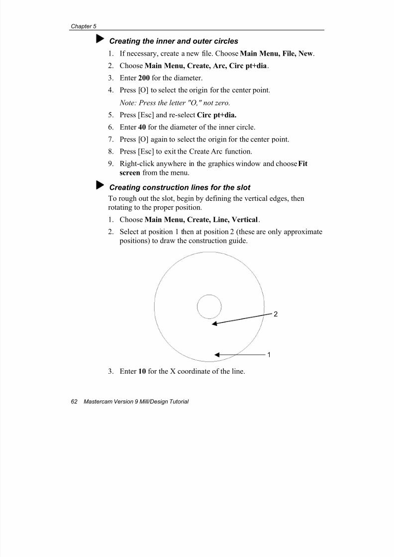
7/18/2019 V9 Mill-Design Tutorial (metric).pdf
http://slidepdf.com/reader/full/v9-mill-design-tutorial-metricpdf 74/453
Chapter 5
62 Mastercam Version 9 Mill/Design Tutorial
Creating the inner and outer circles
1. If necessary, create a new file. Choose Main Menu, File, New.
2. Choose Main Menu, Create, Arc, Circ pt+dia.
3. Enter 200 for the diameter.
4. Press [O] to select the origin for the center point.
Note: Press the letter "O," not zero.
5. Press [Esc] and re-select Circ pt+dia.
6. Enter 40 for the diameter of the inner circle.
7. Press [O] again to select the origin for the center point.
8. Press [Esc] to exit the Create Arc function.
9. Right-click anywhere in the graphics window and choose Fit
screen from the menu.
Creating construction lines for the slot
To rough out the slot, begin by defining the vertical edges, then
rotating to the proper position.
1. Choose Main Menu, Create, Line, Vertical.
2. Select at position 1 then at position 2 (these are only approximate
positions) to draw the construction guide.
3. Enter 10 for the X coordinate of the line.
1
2
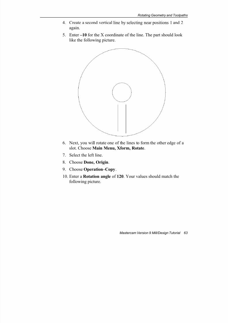
7/18/2019 V9 Mill-Design Tutorial (metric).pdf
http://slidepdf.com/reader/full/v9-mill-design-tutorial-metricpdf 75/453
Rotating Geometry and Toolpaths
Mastercam Version 9 Mill/Design Tutorial 63
4. Create a second vertical line by selecting near positions 1 and 2
again.
5. Enter –10 for the X coordinate of the line. The part should look
like the following picture.
6. Next, you will rotate one of the lines to form the other edge of a
slot. Choose Main Menu, Xform, Rotate.
7. Select the left line.
8. Choose Done, Origin.
9. Choose Operation–Copy.10. Enter a Rotation angle of 120. Your values should match the
following picture.
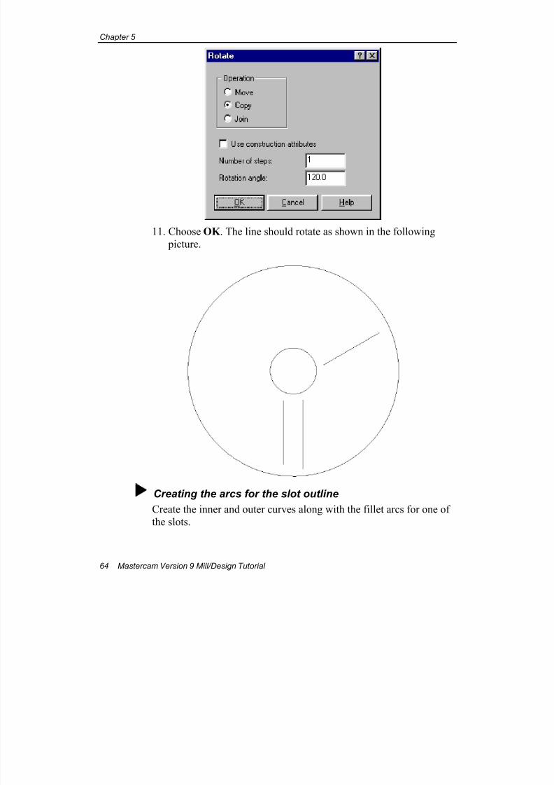
7/18/2019 V9 Mill-Design Tutorial (metric).pdf
http://slidepdf.com/reader/full/v9-mill-design-tutorial-metricpdf 76/453
Chapter 5
64 Mastercam Version 9 Mill/Design Tutorial
11. Choose OK . The line should rotate as shown in the following
picture.
Creating the arcs for the slot outline
Create the inner and outer curves along with the fillet arcs for one of
the slots.
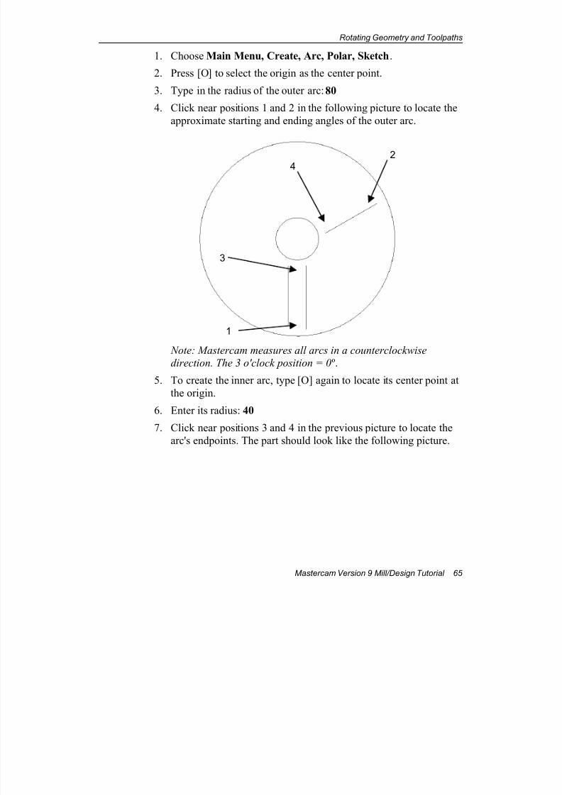
7/18/2019 V9 Mill-Design Tutorial (metric).pdf
http://slidepdf.com/reader/full/v9-mill-design-tutorial-metricpdf 77/453
Rotating Geometry and Toolpaths
Mastercam Version 9 Mill/Design Tutorial 65
1. Choose Main Menu, Create, Arc, Polar, Sketch.
2. Press [O] to select the origin as the center point.
3. Type in the radius of the outer arc: 80
4. Click near positions 1 and 2 in the following picture to locate the
approximate starting and ending angles of the outer arc.
Note: Mastercam measures all arcs in a counterclockwise
direction. The 3 o'clock position = 0 º.
5. To create the inner arc, type [O] again to locate its center point at
the origin.
6. Enter its radius: 40
7. Click near positions 3 and 4 in the previous picture to locate the
arc's endpoints. The part should look like the following picture.
1
24
3
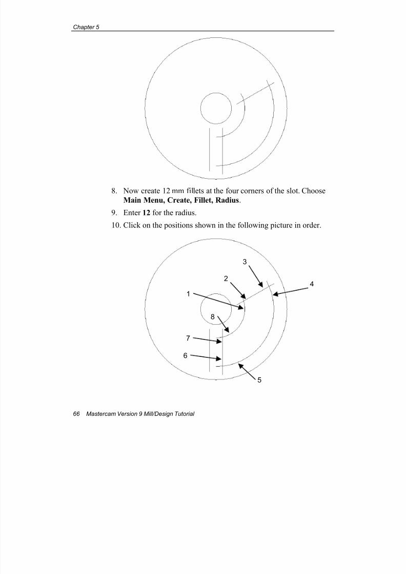
7/18/2019 V9 Mill-Design Tutorial (metric).pdf
http://slidepdf.com/reader/full/v9-mill-design-tutorial-metricpdf 78/453
Chapter 5
66 Mastercam Version 9 Mill/Design Tutorial
8. Now create 12 mm fillets at the four corners of the slot. Choose
Main Menu, Create, Fillet, Radius.9. Enter 12 for the radius.
10. Click on the positions shown in the following picture in order.
1
24
3
8
7
6
5

7/18/2019 V9 Mill-Design Tutorial (metric).pdf
http://slidepdf.com/reader/full/v9-mill-design-tutorial-metricpdf 79/453
Rotating Geometry and Toolpaths
Mastercam Version 9 Mill/Design Tutorial 67
The part with the fillets should look like the following picture.
Completing the first slot
To complete the first slot, you need to create the flat edge on the
outside radius. First you will create the horizontal line. Then you will
rotate it into position and create the arcs that connect it to the slot.
1. Choose Main Menu, Create, Line, Endpoints.
2. Enter the coordinates for the first endpoint: –12.5, 75
3. Enter the coordinates for the second endpoint: 12.5, 75. The line
should look like the following picture.
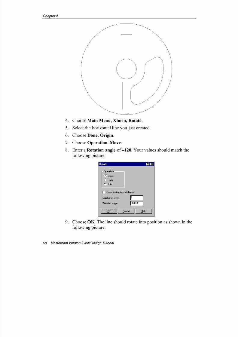
7/18/2019 V9 Mill-Design Tutorial (metric).pdf
http://slidepdf.com/reader/full/v9-mill-design-tutorial-metricpdf 80/453
Chapter 5
68 Mastercam Version 9 Mill/Design Tutorial
4. Choose Main Menu, Xform, Rotate.
5. Select the horizontal line you just created.
6. Choose Done, Origin.
7. Choose Operation–Move.
8. Enter a Rotation angle of –120. Your values should match the
following picture.
9. Choose OK . The line should rotate into position as shown in the
following picture.
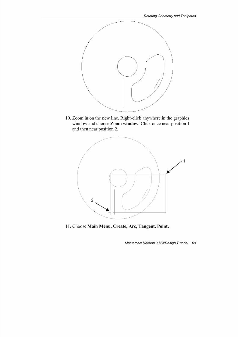
7/18/2019 V9 Mill-Design Tutorial (metric).pdf
http://slidepdf.com/reader/full/v9-mill-design-tutorial-metricpdf 81/453
Rotating Geometry and Toolpaths
Mastercam Version 9 Mill/Design Tutorial 69
10. Zoom in on the new line. Right-click anywhere in the graphicswindow and choose Zoom window. Click once near position 1
and then near position 2.
11. Choose Main Menu, Create, Arc, Tangent, Point.
1
2
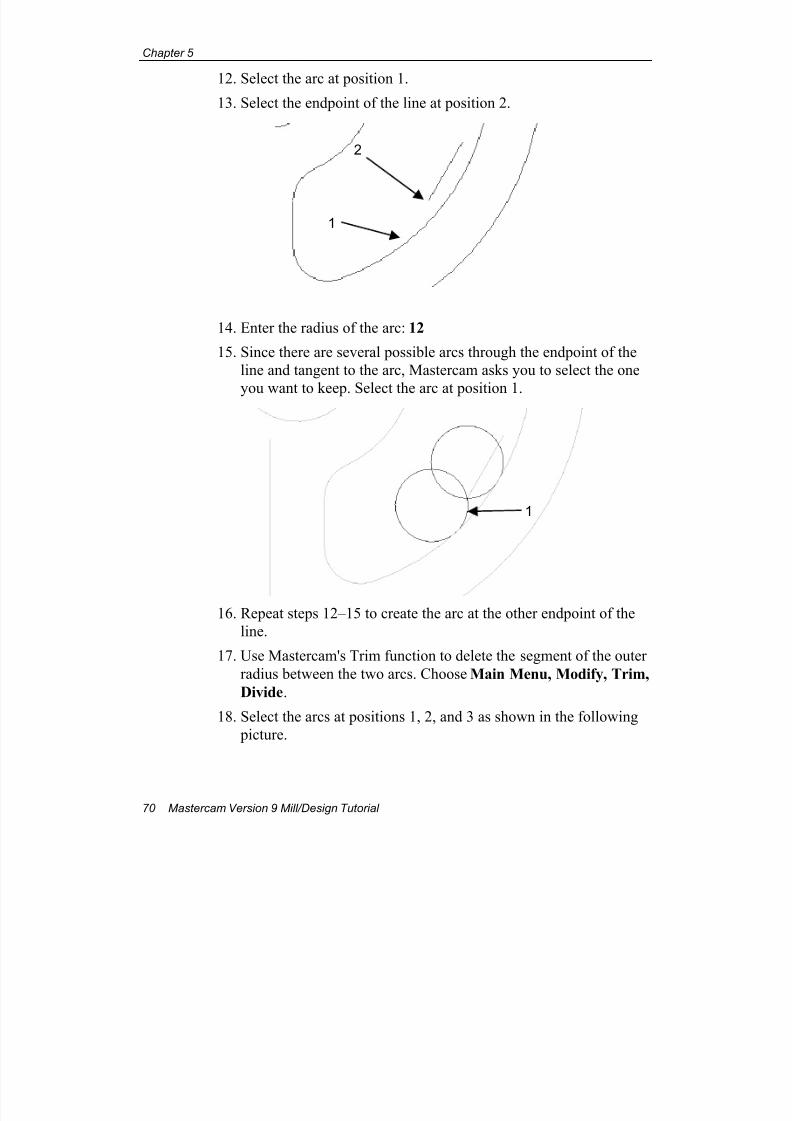
7/18/2019 V9 Mill-Design Tutorial (metric).pdf
http://slidepdf.com/reader/full/v9-mill-design-tutorial-metricpdf 82/453
Chapter 5
70 Mastercam Version 9 Mill/Design Tutorial
12. Select the arc at position 1.
13. Select the endpoint of the line at position 2.
14. Enter the radius of the arc: 12
15. Since there are several possible arcs through the endpoint of the
line and tangent to the arc, Mastercam asks you to select the one
you want to keep. Select the arc at position 1.
16. Repeat steps 12–15 to create the arc at the other endpoint of the
line.
17. Use Mastercam's Trim function to delete the segment of the outer
radius between the two arcs. Choose Main Menu, Modify, Trim,
Divide.
18. Select the arcs at positions 1, 2, and 3 as shown in the following
picture.
1
2
1
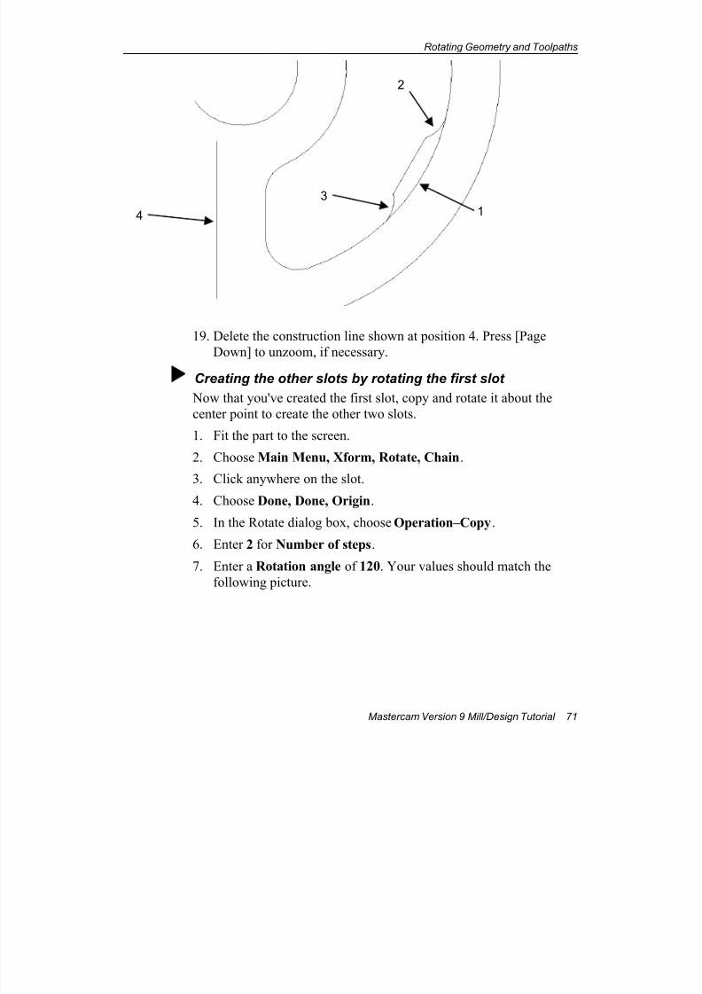
7/18/2019 V9 Mill-Design Tutorial (metric).pdf
http://slidepdf.com/reader/full/v9-mill-design-tutorial-metricpdf 83/453
Rotating Geometry and Toolpaths
Mastercam Version 9 Mill/Design Tutorial 71
19. Delete the construction line shown at position 4. Press [Page
Down] to unzoom, if necessary.
Creating the other slots by rotating the first slot
Now that you've created the first slot, copy and rotate it about the
center point to create the other two slots.
1. Fit the part to the screen.
2. Choose Main Menu, Xform, Rotate, Chain.
3. Click anywhere on the slot.
4. Choose Done, Done, Origin.
5. In the Rotate dialog box, choose Operation–Copy.
6. Enter 2 for Number of steps.
7. Enter a Rotation angle of 120. Your values should match the
following picture.
14
3
2
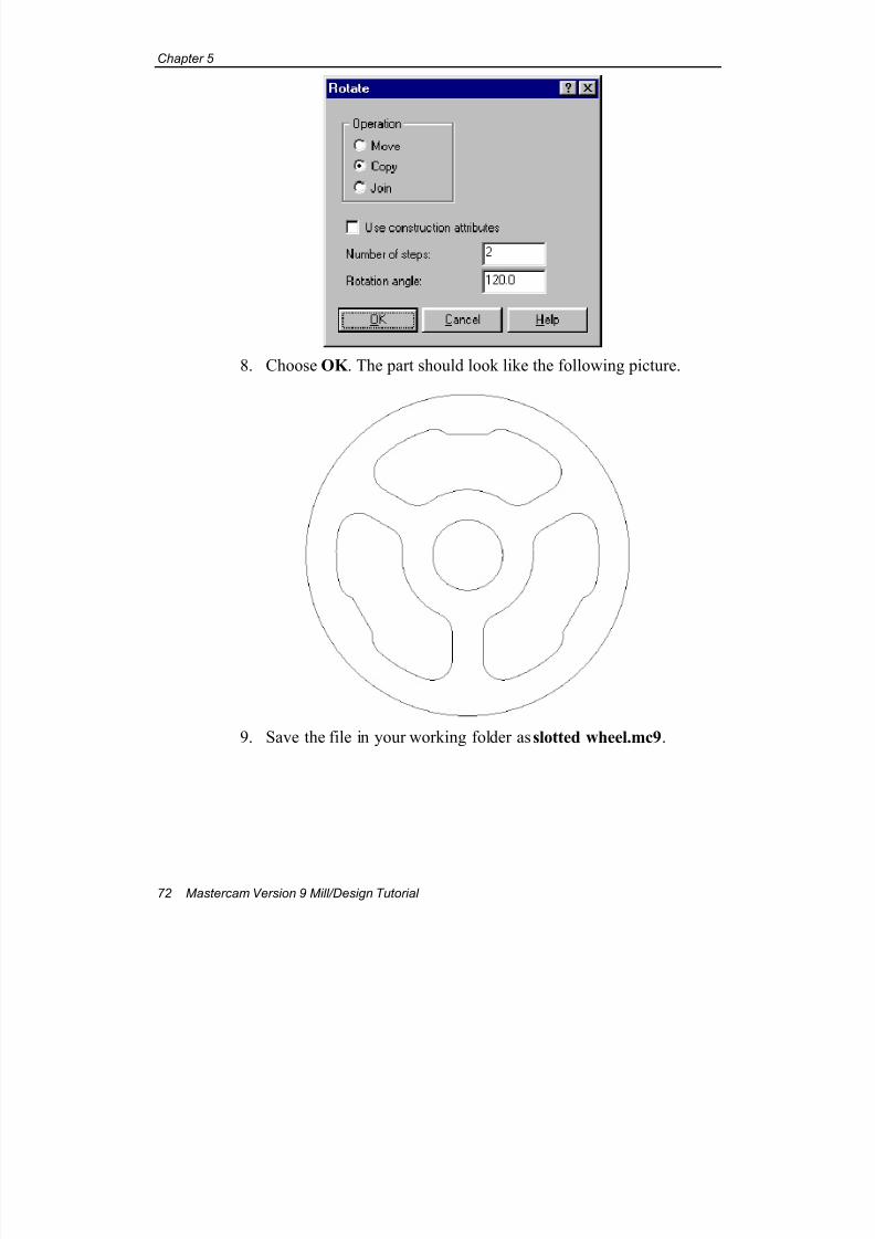
7/18/2019 V9 Mill-Design Tutorial (metric).pdf
http://slidepdf.com/reader/full/v9-mill-design-tutorial-metricpdf 84/453
Chapter 5
72 Mastercam Version 9 Mill/Design Tutorial
8. Choose OK . The part should look like the following picture.
9. Save the file in your working folder as slotted wheel.mc9.
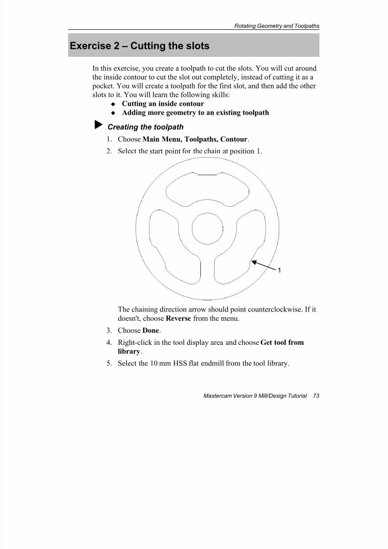
7/18/2019 V9 Mill-Design Tutorial (metric).pdf
http://slidepdf.com/reader/full/v9-mill-design-tutorial-metricpdf 85/453
Rotating Geometry and Toolpaths
Mastercam Version 9 Mill/Design Tutorial 73
Exercise 2 – Cutting the slots
In this exercise, you create a toolpath to cut the slots. You will cut around
the inside contour to cut the slot out completely, instead of cutting it as a
pocket. You will create a toolpath for the first slot, and then add the other
slots to it. You will learn the following skills: Cutting an inside contour
Adding more geometry to an existing toolpath
Creating the toolpath
1. Choose Main Menu, Toolpaths, Contour.
2. Select the start point for the chain at position 1.
The chaining direction arrow should point counterclockwise. If it
doesn't, choose Reverse from the menu.
3. Choose Done.
4. Right-click in the tool display area and choose Get tool from
library.
5. Select the 10 mm HSS flat endmill from the tool library.
1
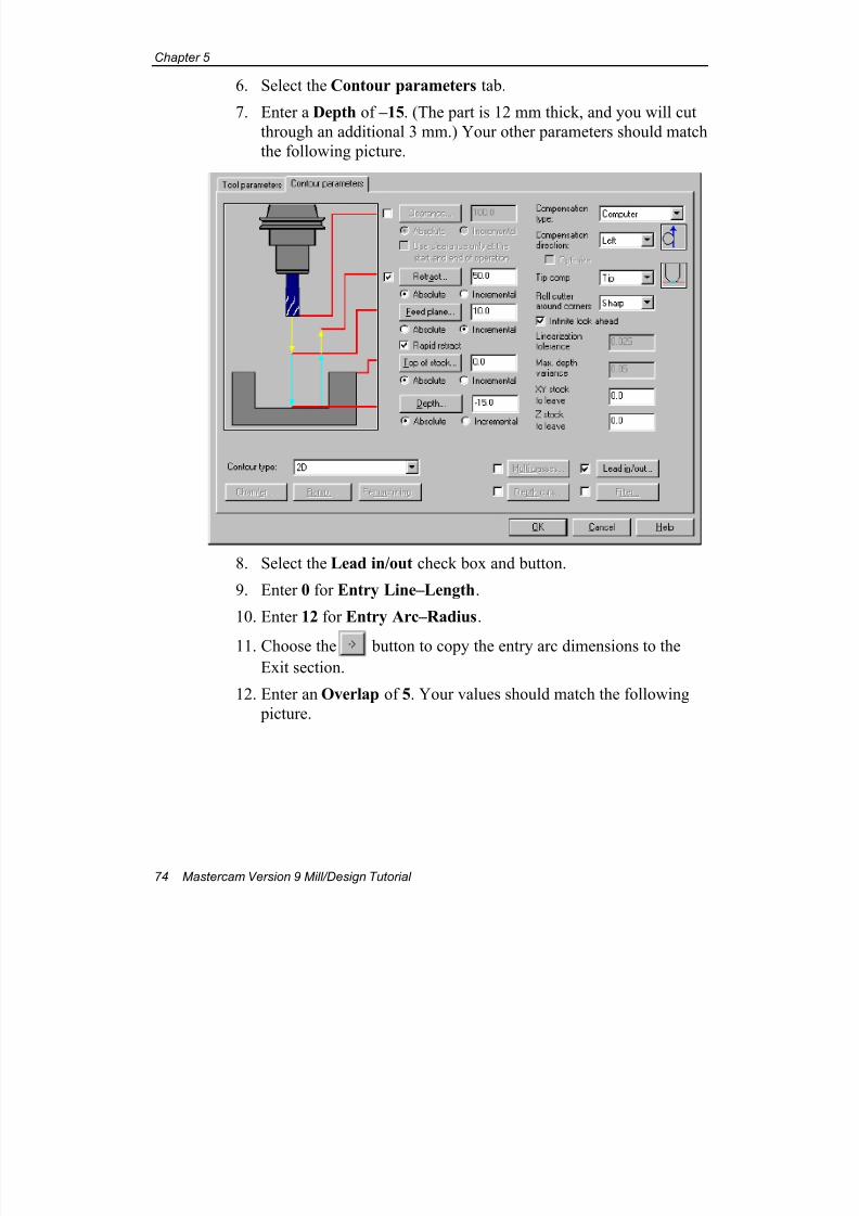
7/18/2019 V9 Mill-Design Tutorial (metric).pdf
http://slidepdf.com/reader/full/v9-mill-design-tutorial-metricpdf 86/453
Chapter 5
74 Mastercam Version 9 Mill/Design Tutorial
6. Select the Contour parameters tab.
7. Enter a Depth of –15. (The part is 12 mm thick, and you will cut
through an additional 3 mm.) Your other parameters should match
the following picture.
8. Select the Lead in/out check box and button.
9. Enter 0 for Entry Line–Length.
10. Enter 12 for Entry Arc–Radius.
11. Choose the button to copy the entry arc dimensions to the
Exit section.
12. Enter an Overlap of 5. Your values should match the following
picture.
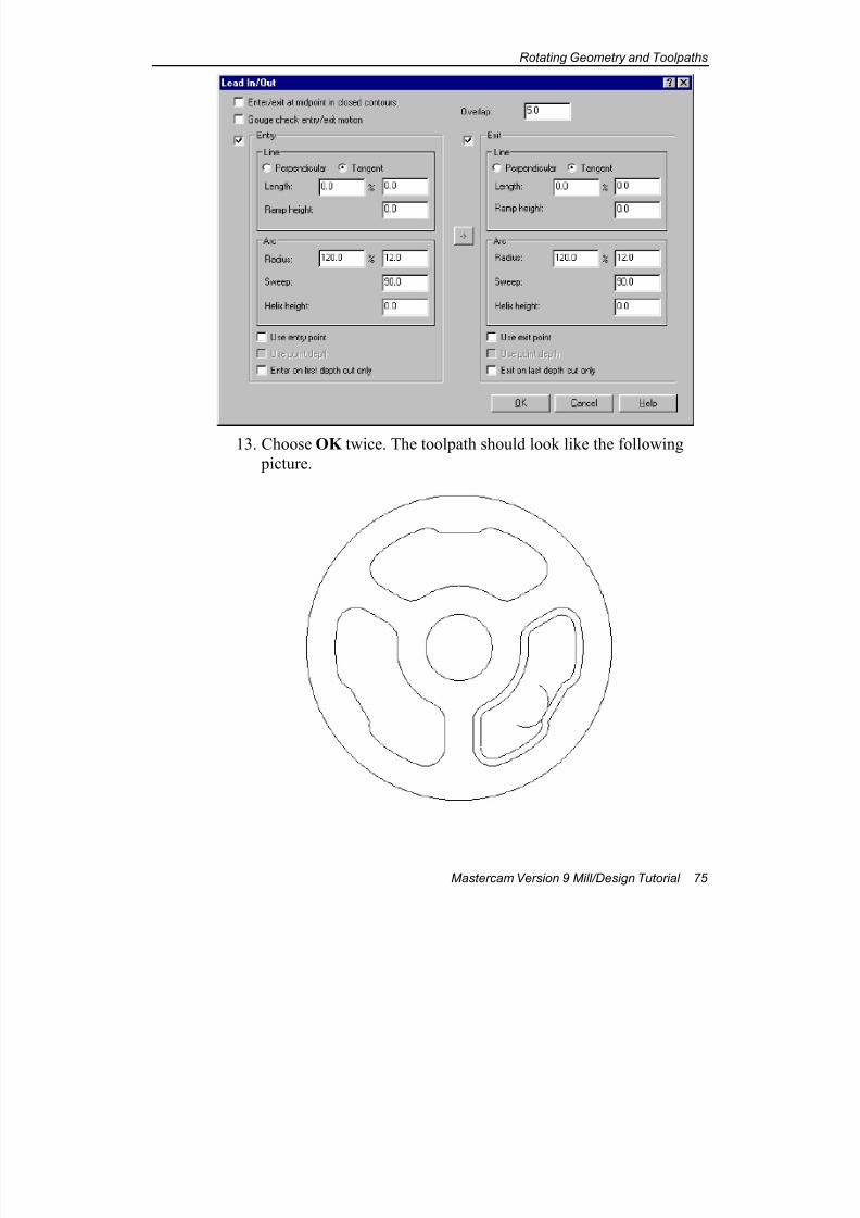
7/18/2019 V9 Mill-Design Tutorial (metric).pdf
http://slidepdf.com/reader/full/v9-mill-design-tutorial-metricpdf 87/453
Rotating Geometry and Toolpaths
Mastercam Version 9 Mill/Design Tutorial 75
13. Choose OK twice. The toolpath should look like the following
picture.
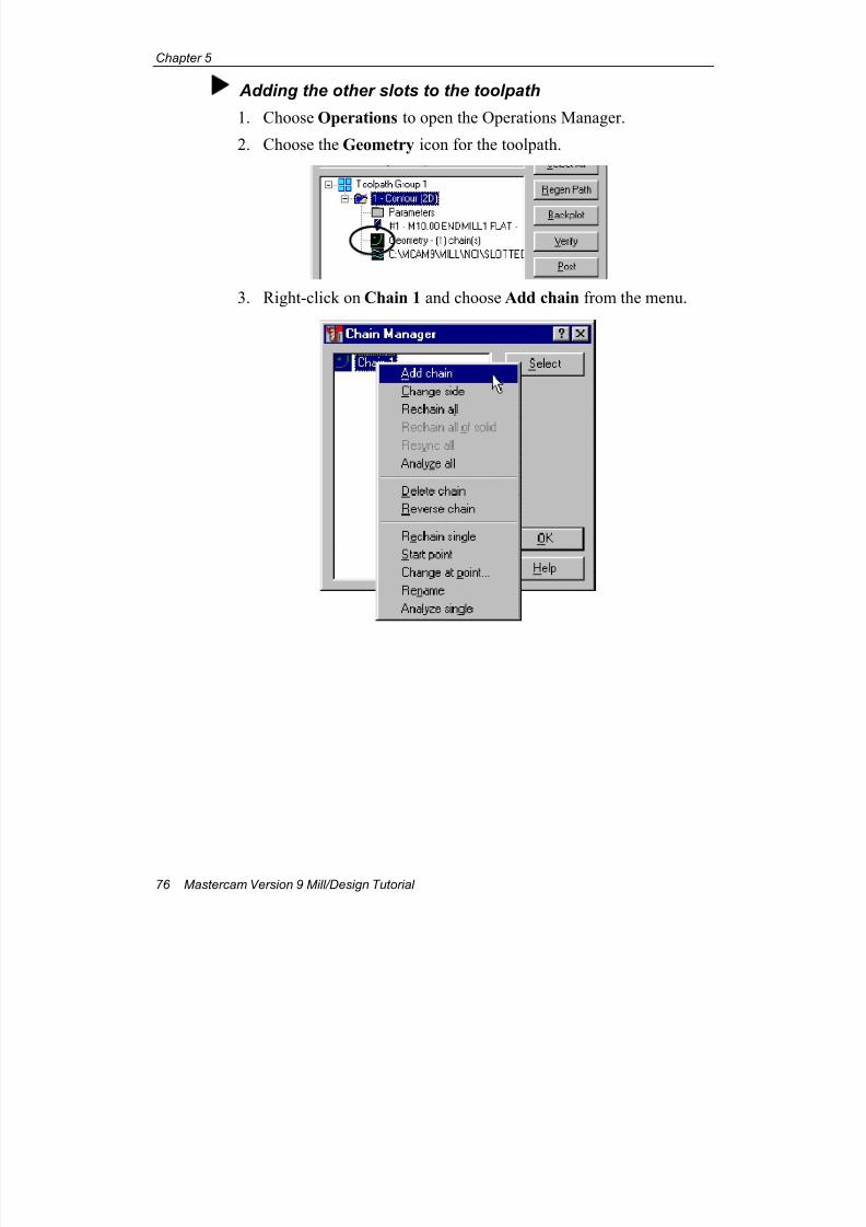
7/18/2019 V9 Mill-Design Tutorial (metric).pdf
http://slidepdf.com/reader/full/v9-mill-design-tutorial-metricpdf 88/453
Chapter 5
76 Mastercam Version 9 Mill/Design Tutorial
Adding the other slots to the toolpath
1. Choose Operations to open the Operations Manager.
2. Choose the Geometry icon for the toolpath.
3. Right-click on Chain 1 and choose Add chain from the menu.
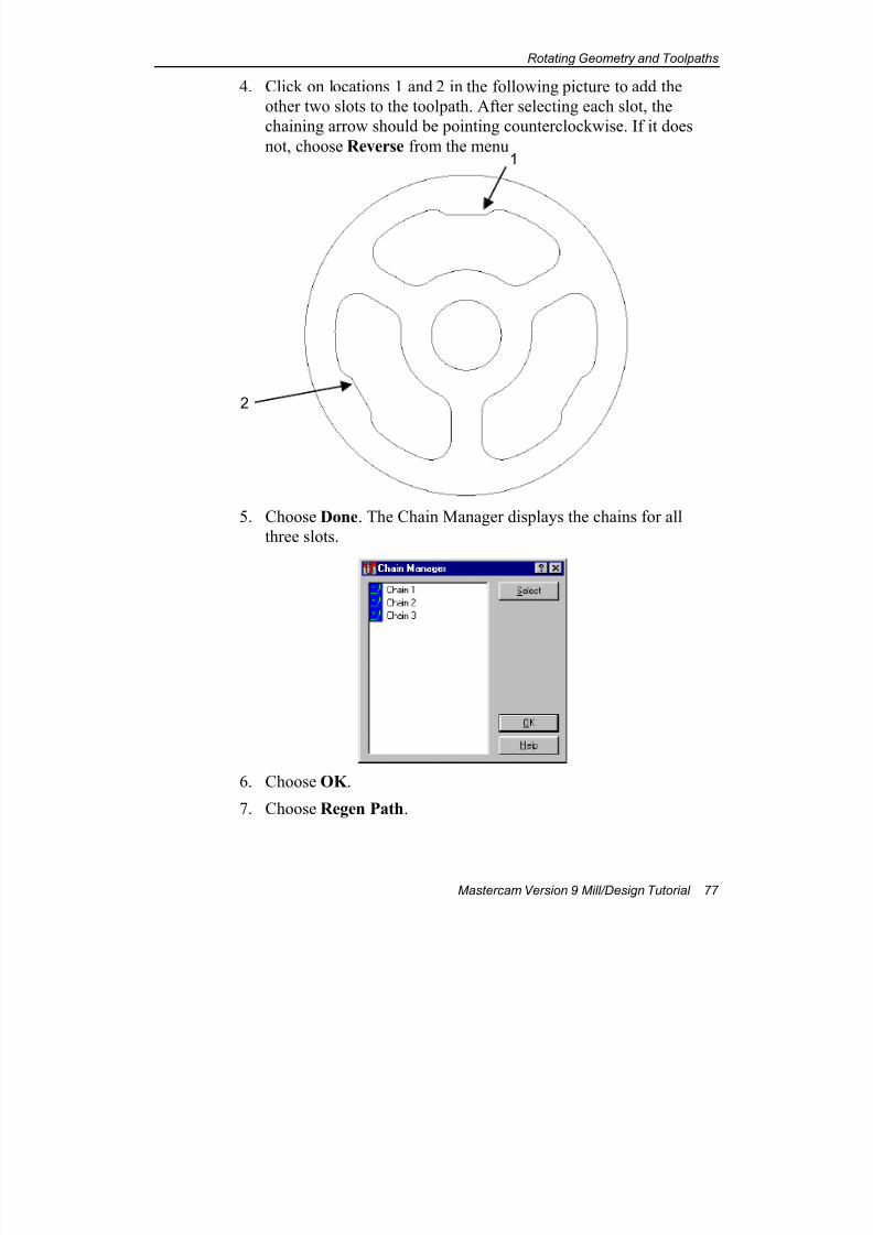
7/18/2019 V9 Mill-Design Tutorial (metric).pdf
http://slidepdf.com/reader/full/v9-mill-design-tutorial-metricpdf 89/453
Rotating Geometry and Toolpaths
Mastercam Version 9 Mill/Design Tutorial 77
4. Click on locations 1 and 2 in the following picture to add the
other two slots to the toolpath. After selecting each slot, the
chaining arrow should be pointing counterclockwise. If it does
not, choose Reverse from the menu.
5. Choose Done. The Chain Manager displays the chains for all
three slots.
6. Choose OK .
7. Choose Regen Path.
2
1
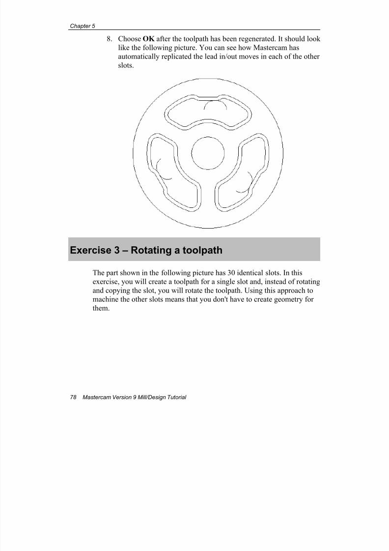
7/18/2019 V9 Mill-Design Tutorial (metric).pdf
http://slidepdf.com/reader/full/v9-mill-design-tutorial-metricpdf 90/453
Chapter 5
78 Mastercam Version 9 Mill/Design Tutorial
8. Choose OK after the toolpath has been regenerated. It should look
like the following picture. You can see how Mastercam has
automatically replicated the lead in/out moves in each of the other
slots.
Exercise 3 – Rotating a toolpath
The part shown in the following picture has 30 identical slots. In this
exercise, you will create a toolpath for a single slot and, instead of rotating
and copying the slot, you will rotate the toolpath. Using this approach tomachine the other slots means that you don't have to create geometry for
them.

7/18/2019 V9 Mill-Design Tutorial (metric).pdf
http://slidepdf.com/reader/full/v9-mill-design-tutorial-metricpdf 91/453
Rotating Geometry and Toolpaths
Mastercam Version 9 Mill/Design Tutorial 79
You will learn the following skill:
Transforming and rotating toolpaths
Creating the toolpath
1. Open the file rotation-mm.mc9.
2. Choose Main Menu, Toolpaths, Contour.

7/18/2019 V9 Mill-Design Tutorial (metric).pdf
http://slidepdf.com/reader/full/v9-mill-design-tutorial-metricpdf 92/453
Chapter 5
80 Mastercam Version 9 Mill/Design Tutorial
3. Select the start point of the chain at position 1. The chain
direction should be counterclockwise.
4. Choose Done.
5. Select a 6 mm HSS flat endmill from the tool library.
6. Choose the Contour parameters tab.
7. Enter a Depth of –6. The rest of the parameters should match the
following picture.
1
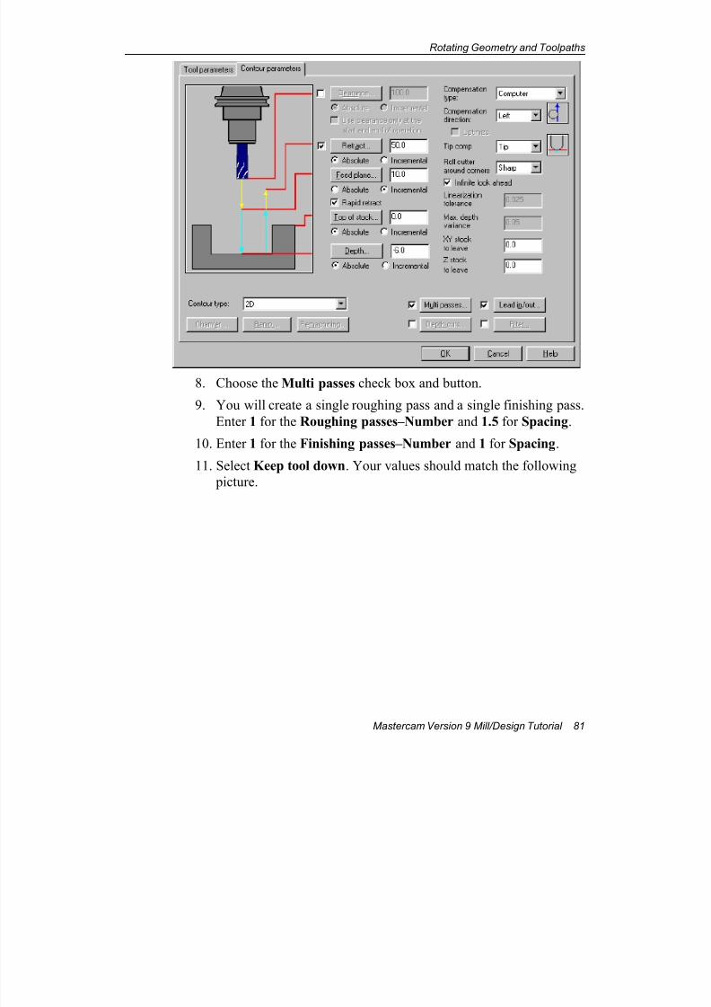
7/18/2019 V9 Mill-Design Tutorial (metric).pdf
http://slidepdf.com/reader/full/v9-mill-design-tutorial-metricpdf 93/453
Rotating Geometry and Toolpaths
Mastercam Version 9 Mill/Design Tutorial 81
8. Choose the Multi passes check box and button.
9. You will create a single roughing pass and a single finishing pass.
Enter 1 for the Roughing passes–Number and 1.5 for Spacing.
10. Enter 1 for the Finishing passes–Number and 1 for Spacing.
11. Select Keep tool down. Your values should match the following
picture.
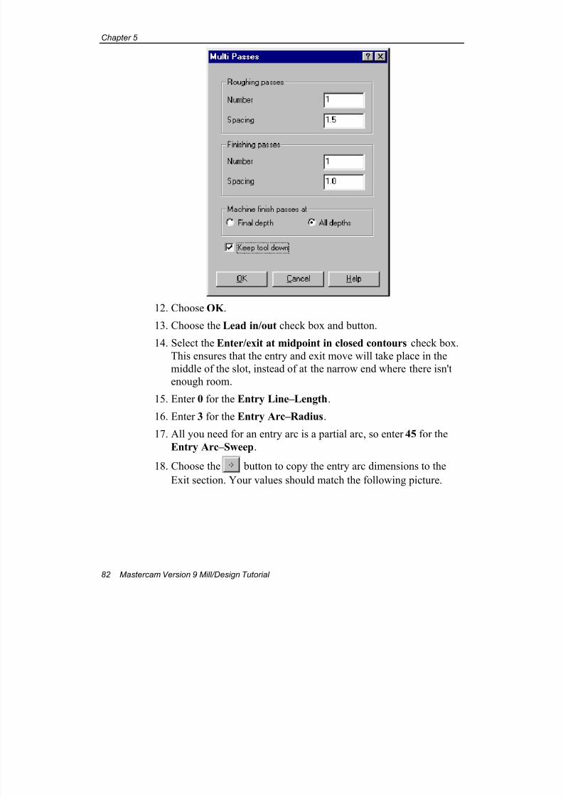
7/18/2019 V9 Mill-Design Tutorial (metric).pdf
http://slidepdf.com/reader/full/v9-mill-design-tutorial-metricpdf 94/453
Chapter 5
82 Mastercam Version 9 Mill/Design Tutorial
12. Choose OK .
13. Choose the Lead in/out check box and button.
14. Select the Enter/exit at midpoint in closed contours check box.
This ensures that the entry and exit move will take place in the
middle of the slot, instead of at the narrow end where there isn't
enough room.
15. Enter 0 for the Entry Line–Length.
16. Enter 3 for the Entry Arc–Radius.17. All you need for an entry arc is a partial arc, so enter 45 for the
Entry Arc–Sweep.
18. Choose the button to copy the entry arc dimensions to the
Exit section. Your values should match the following picture.
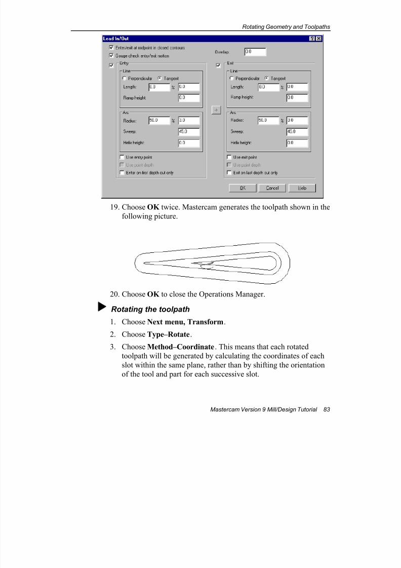
7/18/2019 V9 Mill-Design Tutorial (metric).pdf
http://slidepdf.com/reader/full/v9-mill-design-tutorial-metricpdf 95/453
Rotating Geometry and Toolpaths
Mastercam Version 9 Mill/Design Tutorial 83
19. Choose OK twice. Mastercam generates the toolpath shown in the
following picture.
20. Choose OK to close the Operations Manager.
Rotating the toolpath
1. Choose Next menu, Transform.
2. Choose Type–Rotate.
3. Choose Method–Coordinate. This means that each rotated
toolpath will be generated by calculating the coordinates of each
slot within the same plane, rather than by shifting the orientation
of the tool and part for each successive slot.
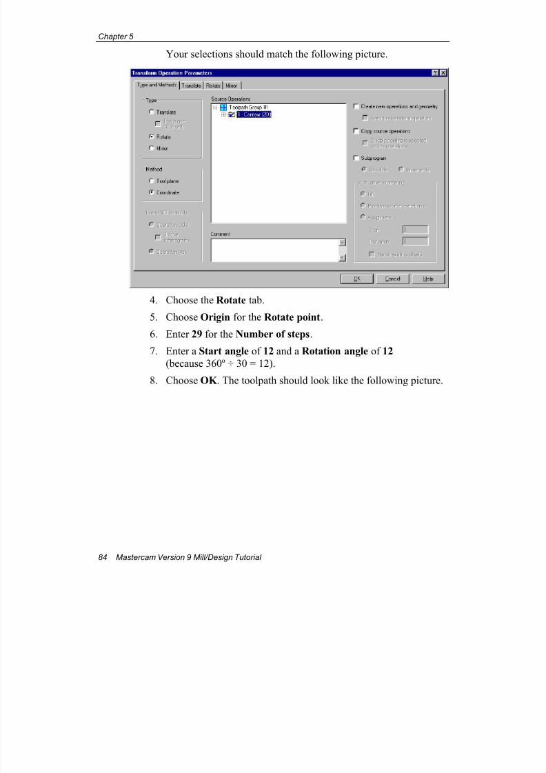
7/18/2019 V9 Mill-Design Tutorial (metric).pdf
http://slidepdf.com/reader/full/v9-mill-design-tutorial-metricpdf 96/453
Chapter 5
84 Mastercam Version 9 Mill/Design Tutorial
Your selections should match the following picture.
4. Choose the Rotate tab.
5. Choose Origin for the Rotate point.
6. Enter 29 for the Number of steps.
7. Enter a Start angle of 12 and a Rotation angle of 12
(because 360º ÷ 30 = 12).
8. Choose OK . The toolpath should look like the following picture.
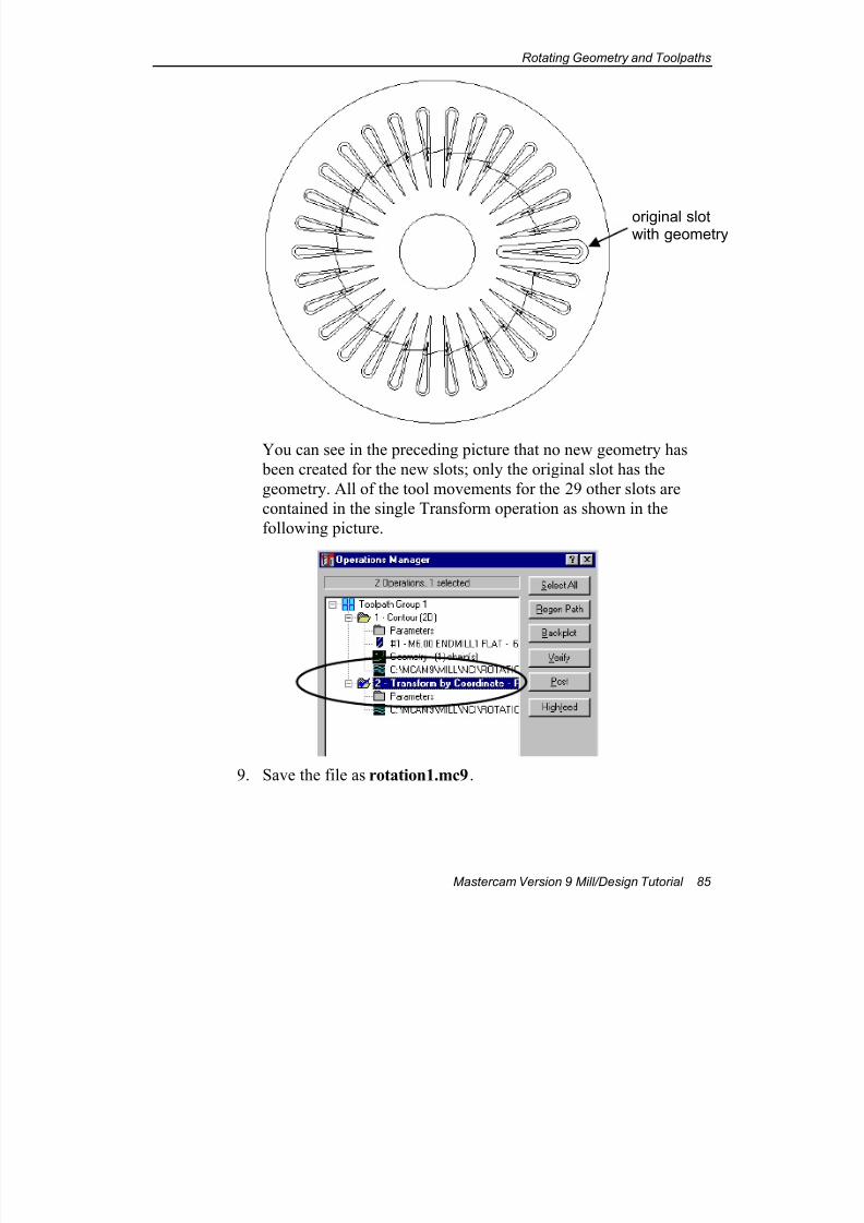
7/18/2019 V9 Mill-Design Tutorial (metric).pdf
http://slidepdf.com/reader/full/v9-mill-design-tutorial-metricpdf 97/453
Rotating Geometry and Toolpaths
Mastercam Version 9 Mill/Design Tutorial 85
You can see in the preceding picture that no new geometry has
been created for the new slots; only the original slot has the
geometry. All of the tool movements for the 29 other slots are
contained in the single Transform operation as shown in the
following picture.
9. Save the file as rotation1.mc9.
original slotwith geometry
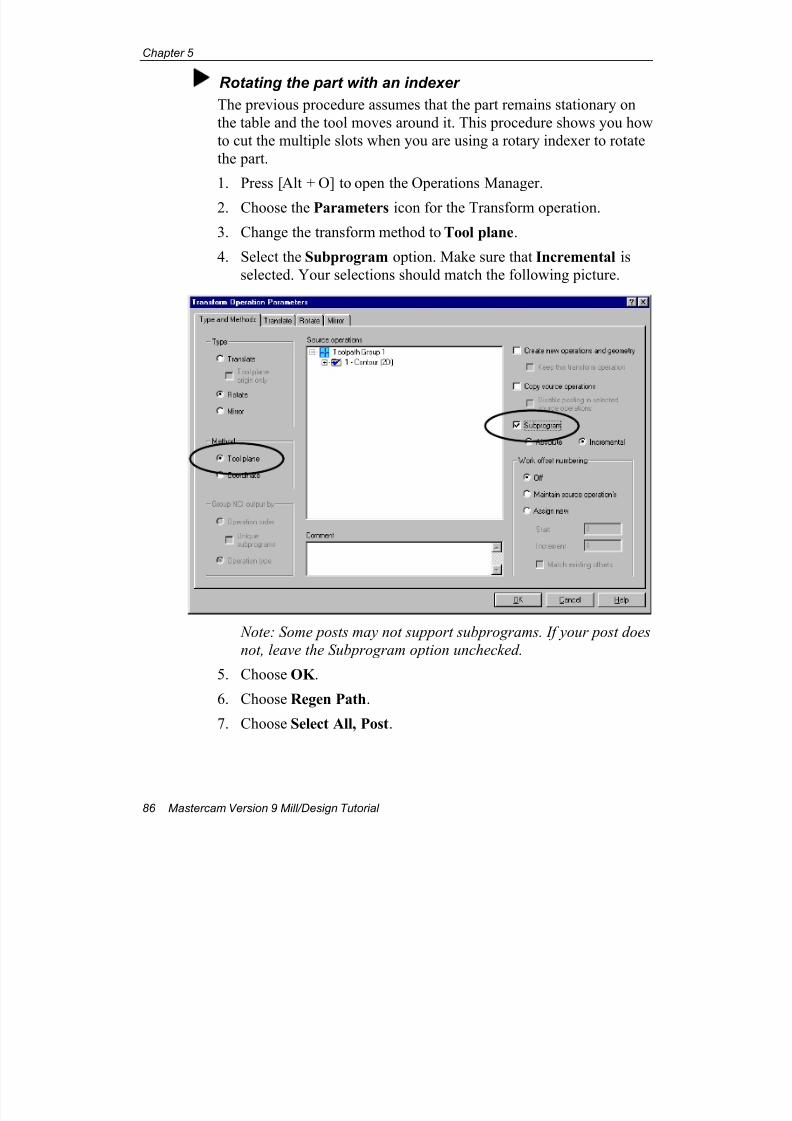
7/18/2019 V9 Mill-Design Tutorial (metric).pdf
http://slidepdf.com/reader/full/v9-mill-design-tutorial-metricpdf 98/453
Chapter 5
86 Mastercam Version 9 Mill/Design Tutorial
Rotating the part with an indexer
The previous procedure assumes that the part remains stationary on
the table and the tool moves around it. This procedure shows you how
to cut the multiple slots when you are using a rotary indexer to rotate
the part.
1. Press [Alt + O] to open the Operations Manager.
2. Choose the Parameters icon for the Transform operation.
3. Change the transform method to Tool plane.
4. Select the Subprogram option. Make sure that Incremental is
selected. Your selections should match the following picture.
Note: Some posts may not support subprograms. If your post does
not, leave the Subprogram option unchecked.
5. Choose OK .
6. Choose Regen Path.
7. Choose Select All, Post.
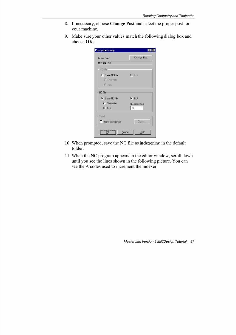
7/18/2019 V9 Mill-Design Tutorial (metric).pdf
http://slidepdf.com/reader/full/v9-mill-design-tutorial-metricpdf 99/453
Rotating Geometry and Toolpaths
Mastercam Version 9 Mill/Design Tutorial 87
8. If necessary, choose Change Post and select the proper post for
your machine.
9. Make sure your other values match the following dialog box and
choose OK .
10. When prompted, save the NC file as indexer.nc in the default
folder.
11. When the NC program appears in the editor window, scroll down
until you see the lines shown in the following picture. You can
see the A codes used to increment the indexer.
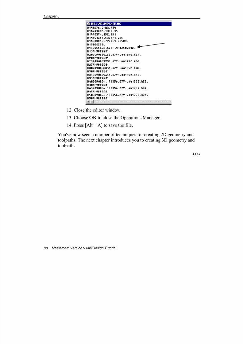
7/18/2019 V9 Mill-Design Tutorial (metric).pdf
http://slidepdf.com/reader/full/v9-mill-design-tutorial-metricpdf 100/453
Chapter 5
88 Mastercam Version 9 Mill/Design Tutorial
12. Close the editor window.
13. Choose OK to close the Operations Manager.
14. Press [Alt + A] to save the file.
You've now seen a number of techniques for creating 2D geometry and
toolpaths. The next chapter introduces you to creating 3D geometry and
toolpaths.
EOC
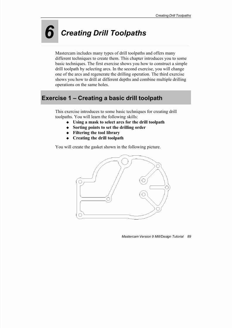
7/18/2019 V9 Mill-Design Tutorial (metric).pdf
http://slidepdf.com/reader/full/v9-mill-design-tutorial-metricpdf 101/453
Creating Drill Toolpaths
Mastercam Version 9 Mill/Design Tutorial 89
6 Creating Drill Toolpaths
Mastercam includes many types of drill toolpaths and offers many
different techniques to create them. This chapter introduces you to some basic techniques. The first exercise shows you how to construct a simple
drill toolpath by selecting arcs. In the second exercise, you will change
one of the arcs and regenerate the drilling operation. The third exercise
shows you how to drill at different depths and combine multiple drilling
operations on the same holes.
Exercise 1 – Creating a basic drill toolpath
This exercise introduces to some basic techniques for creating drill
toolpaths. You will learn the following skills:
Using a mask to select arcs for the drill toolpath
Sorting points to set the drilling order
Filtering the tool library
Creating the drill toolpath
You will create the gasket shown in the following picture.
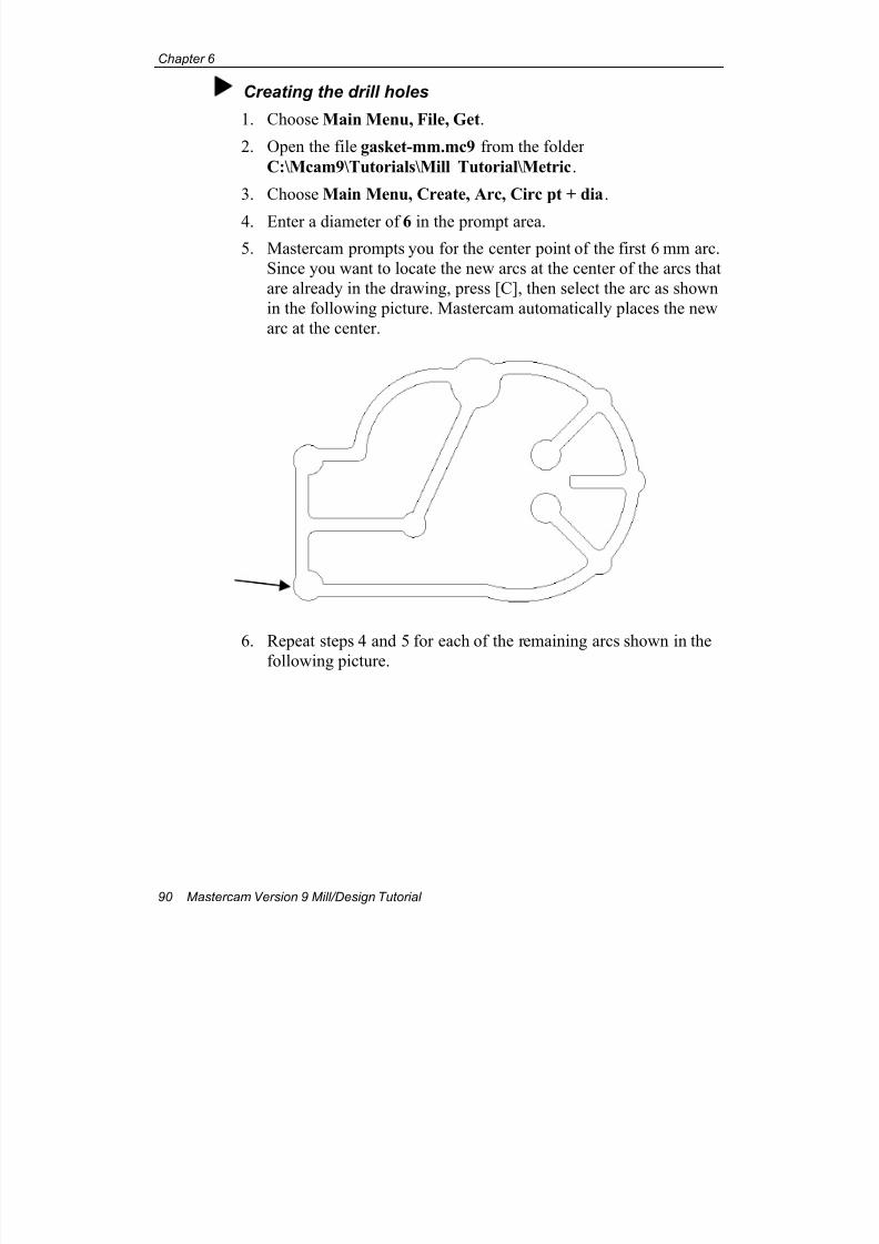
7/18/2019 V9 Mill-Design Tutorial (metric).pdf
http://slidepdf.com/reader/full/v9-mill-design-tutorial-metricpdf 102/453
Chapter 6
90 Mastercam Version 9 Mill/Design Tutorial
Creating the drill holes
1. Choose Main Menu, File, Get.
2. Open the file gasket-mm.mc9 from the folder
C:\Mcam9\Tutorials\Mill Tutorial\Metric.
3. Choose Main Menu, Create, Arc, Circ pt + dia.
4. Enter a diameter of 6 in the prompt area.
5. Mastercam prompts you for the center point of the first 6 mm arc.
Since you want to locate the new arcs at the center of the arcs that
are already in the drawing, press [C], then select the arc as shown
in the following picture. Mastercam automatically places the new
arc at the center.
6. Repeat steps 4 and 5 for each of the remaining arcs shown in the
following picture.
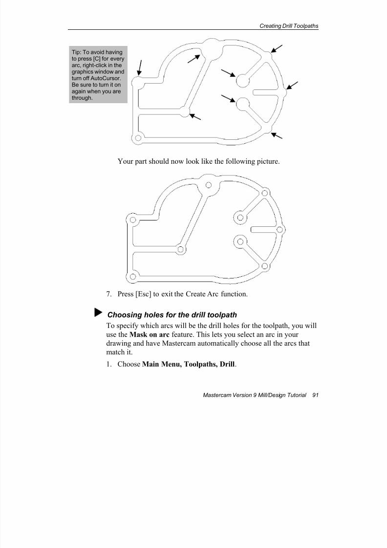
7/18/2019 V9 Mill-Design Tutorial (metric).pdf
http://slidepdf.com/reader/full/v9-mill-design-tutorial-metricpdf 103/453
Creating Drill Toolpaths
Mastercam Version 9 Mill/Design Tutorial 91
Your part should now look like the following picture.
7. Press [Esc] to exit the Create Arc function.
Choosing holes for the drill toolpath
To specify which arcs will be the drill holes for the toolpath, you will
use the Mask on arc feature. This lets you select an arc in your
drawing and have Mastercam automatically choose all the arcs that
match it.
1. Choose Main Menu, Toolpaths, Drill.
Tip: To avoid havingto press [C] for everyarc, right-click in thegraphics window andturn off AutoCursor.Be sure to turn it onagain when you are
through.
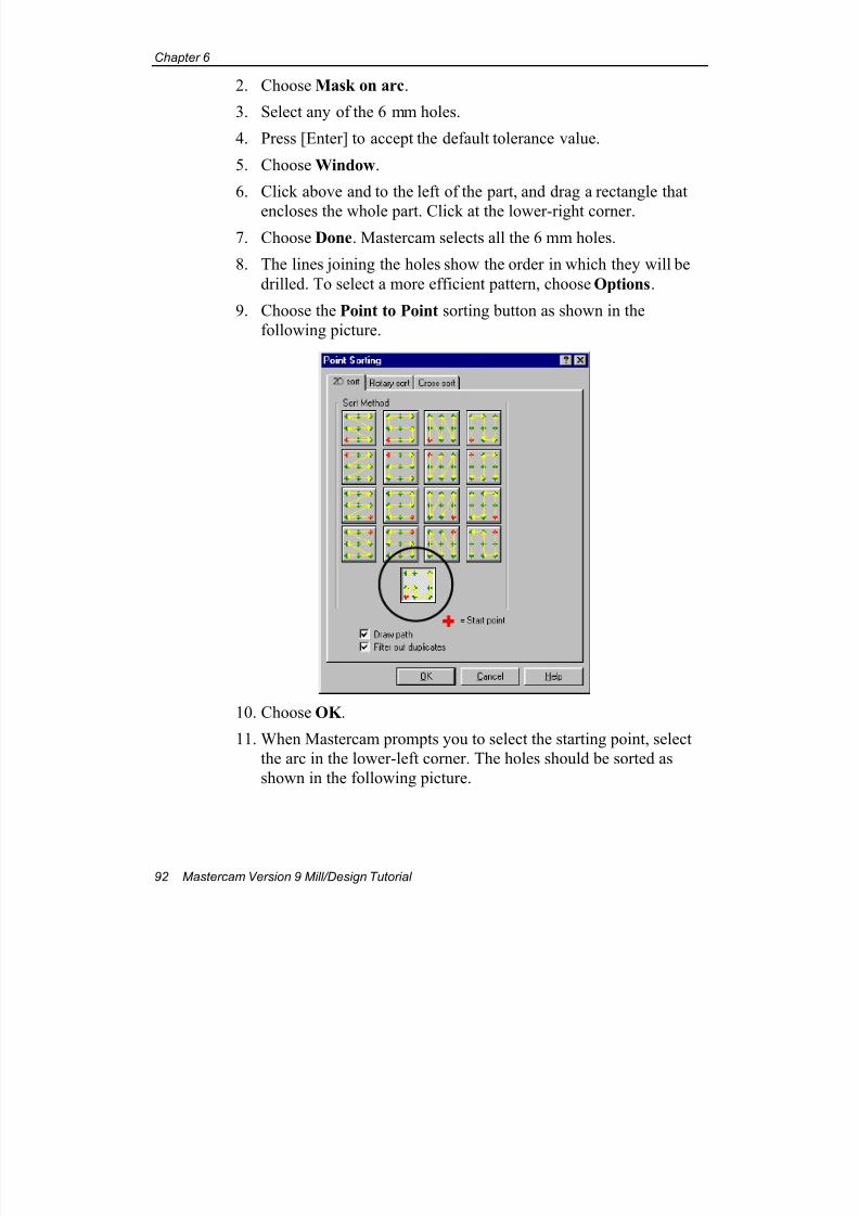
7/18/2019 V9 Mill-Design Tutorial (metric).pdf
http://slidepdf.com/reader/full/v9-mill-design-tutorial-metricpdf 104/453
Chapter 6
92 Mastercam Version 9 Mill/Design Tutorial
2. Choose Mask on arc.
3. Select any of the 6 mm holes.
4. Press [Enter] to accept the default tolerance value.
5. Choose Window.
6. Click above and to the left of the part, and drag a rectangle that
encloses the whole part. Click at the lower-right corner.7. Choose Done. Mastercam selects all the 6 mm holes.
8. The lines joining the holes show the order in which they will be
drilled. To select a more efficient pattern, choose Options.
9. Choose the Point to Point sorting button as shown in the
following picture.
10. Choose OK .
11. When Mastercam prompts you to select the starting point, select
the arc in the lower-left corner. The holes should be sorted as
shown in the following picture.
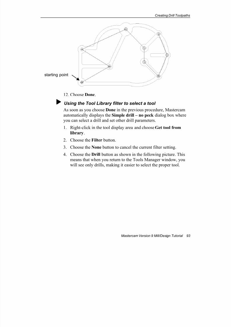
7/18/2019 V9 Mill-Design Tutorial (metric).pdf
http://slidepdf.com/reader/full/v9-mill-design-tutorial-metricpdf 105/453
Creating Drill Toolpaths
Mastercam Version 9 Mill/Design Tutorial 93
12. Choose Done.
Using the Tool Library filter to select a tool
As soon as you choose Done in the previous procedure, Mastercam
automatically displays the Simple drill – no peck dialog box whereyou can select a drill and set other drill parameters.
1. Right-click in the tool display area and choose Get tool from
library.
2. Choose the Filter button.
3. Choose the None button to cancel the current filter setting.
4. Choose the Drill button as shown in the following picture. This
means that when you return to the Tools Manager window, you
will see only drills, making it easier to select the proper tool.
starting point
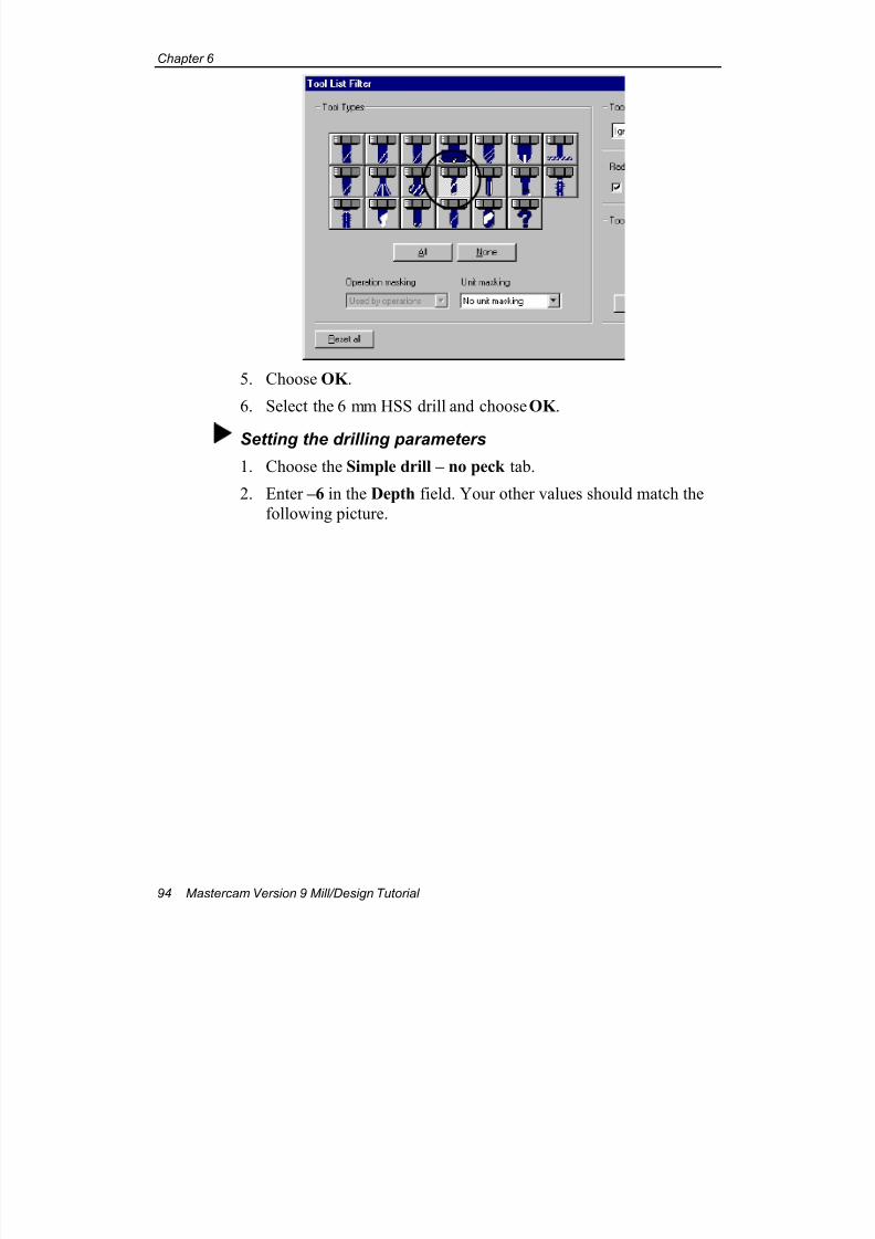
7/18/2019 V9 Mill-Design Tutorial (metric).pdf
http://slidepdf.com/reader/full/v9-mill-design-tutorial-metricpdf 106/453
Chapter 6
94 Mastercam Version 9 Mill/Design Tutorial
5. Choose OK .
6. Select the 6 mm HSS drill and choose OK .
Setting the drilling parameters
1. Choose the Simple drill – no peck tab.
2. Enter –6 in the Depth field. Your other values should match the
following picture.
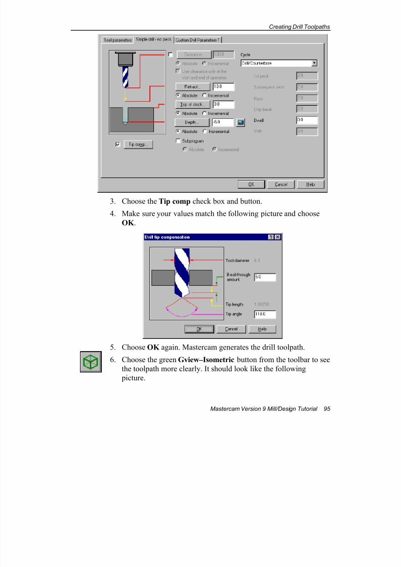
7/18/2019 V9 Mill-Design Tutorial (metric).pdf
http://slidepdf.com/reader/full/v9-mill-design-tutorial-metricpdf 107/453
Creating Drill Toolpaths
Mastercam Version 9 Mill/Design Tutorial 95
3. Choose the Tip comp check box and button.
4. Make sure your values match the following picture and choose
OK .
5. Choose OK again. Mastercam generates the drill toolpath.
6. Choose the green Gview–Isometric button from the toolbar to see
the toolpath more clearly. It should look like the following
picture.
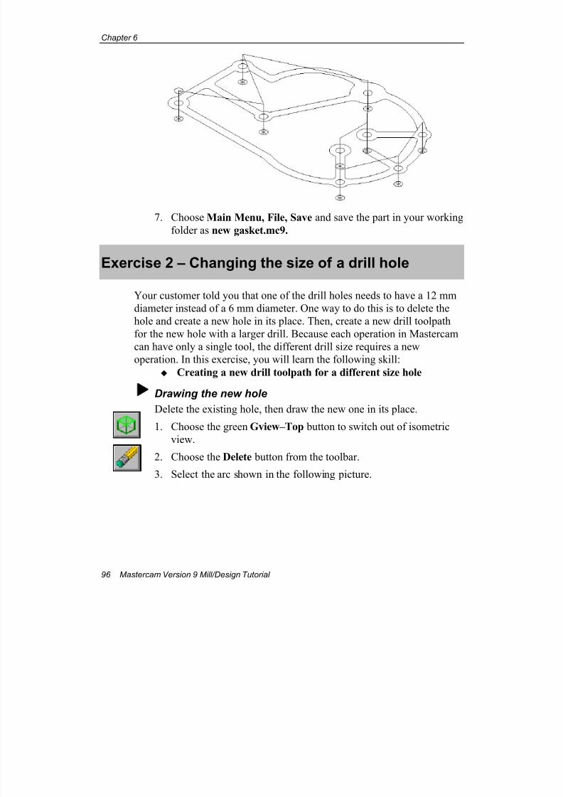
7/18/2019 V9 Mill-Design Tutorial (metric).pdf
http://slidepdf.com/reader/full/v9-mill-design-tutorial-metricpdf 108/453
Chapter 6
96 Mastercam Version 9 Mill/Design Tutorial
7. Choose Main Menu, File, Save and save the part in your working
folder as new gasket.mc9.
Exercise 2 – Changing the size of a drill hole
Your customer told you that one of the drill holes needs to have a 12 mm
diameter instead of a 6 mm diameter. One way to do this is to delete the
hole and create a new hole in its place. Then, create a new drill toolpath
for the new hole with a larger drill. Because each operation in Mastercam
can have only a single tool, the different drill size requires a new
operation. In this exercise, you will learn the following skill:
Creating a new drill toolpath for a different size hole
Drawing the new hole
Delete the existing hole, then draw the new one in its place.
1. Choose the green Gview–Top button to switch out of isometric
view.
2. Choose the Delete button from the toolbar.
3. Select the arc shown in the following picture.
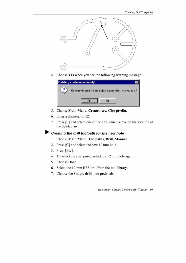
7/18/2019 V9 Mill-Design Tutorial (metric).pdf
http://slidepdf.com/reader/full/v9-mill-design-tutorial-metricpdf 109/453
Creating Drill Toolpaths
Mastercam Version 9 Mill/Design Tutorial 97
4. Choose Yes when you see the following warning message.
5. Choose Main Menu, Create, Arc, Circ pt+dia.
6. Enter a diameter of 12.
7. Press [C] and select one of the arcs which surround the location of
the deleted arc.
Creating the drill toolpath for the new hole
1. Choose Main Menu, Toolpaths, Drill, Manual.
2. Press [C] and select the new 12 mm hole.
3. Press [Esc].
4. To select the start point, select the 12 mm hole again.
5. Choose Done.
6. Select the 12 mm HSS drill from the tool library.
7. Choose the Simple drill – no peck tab.
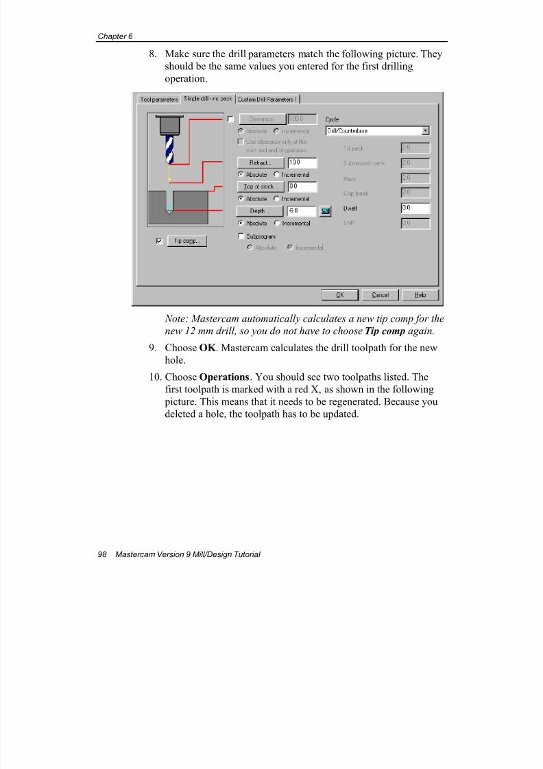
7/18/2019 V9 Mill-Design Tutorial (metric).pdf
http://slidepdf.com/reader/full/v9-mill-design-tutorial-metricpdf 110/453
Chapter 6
98 Mastercam Version 9 Mill/Design Tutorial
8. Make sure the drill parameters match the following picture. They
should be the same values you entered for the first drilling
operation.
Note: Mastercam automatically calculates a new tip comp for the
new 12 mm drill, so you do not have to choose Tip comp again.
9. Choose OK . Mastercam calculates the drill toolpath for the new
hole.
10. Choose Operations. You should see two toolpaths listed. The
first toolpath is marked with a red X, as shown in the following
picture. This means that it needs to be regenerated. Because youdeleted a hole, the toolpath has to be updated.
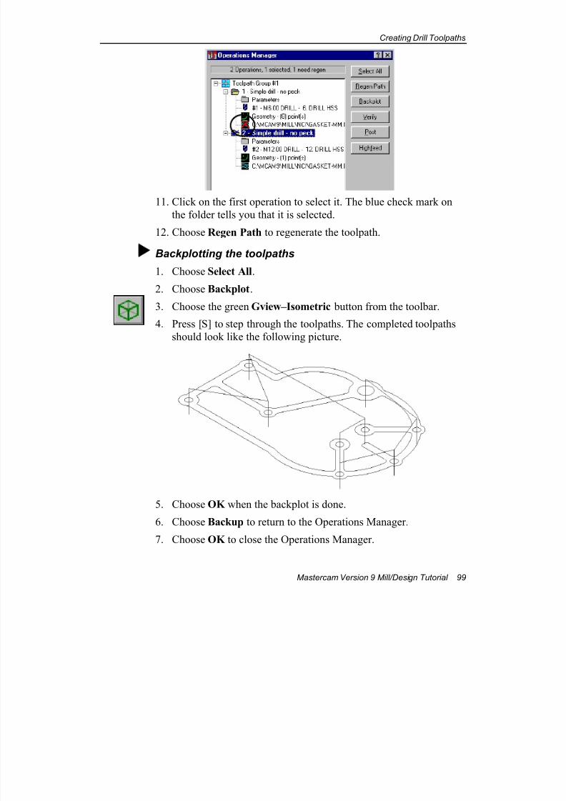
7/18/2019 V9 Mill-Design Tutorial (metric).pdf
http://slidepdf.com/reader/full/v9-mill-design-tutorial-metricpdf 111/453
Creating Drill Toolpaths
Mastercam Version 9 Mill/Design Tutorial 99
11. Click on the first operation to select it. The blue check mark on
the folder tells you that it is selected.
12. Choose Regen Path to regenerate the toolpath.
Backplotting the toolpaths
1. Choose Select All.
2. Choose Backplot.
3. Choose the green Gview–Isometric button from the toolbar.
4. Press [S] to step through the toolpaths. The completed toolpaths
should look like the following picture.
5. Choose OK when the backplot is done.
6. Choose Backup to return to the Operations Manager.
7. Choose OK to close the Operations Manager.
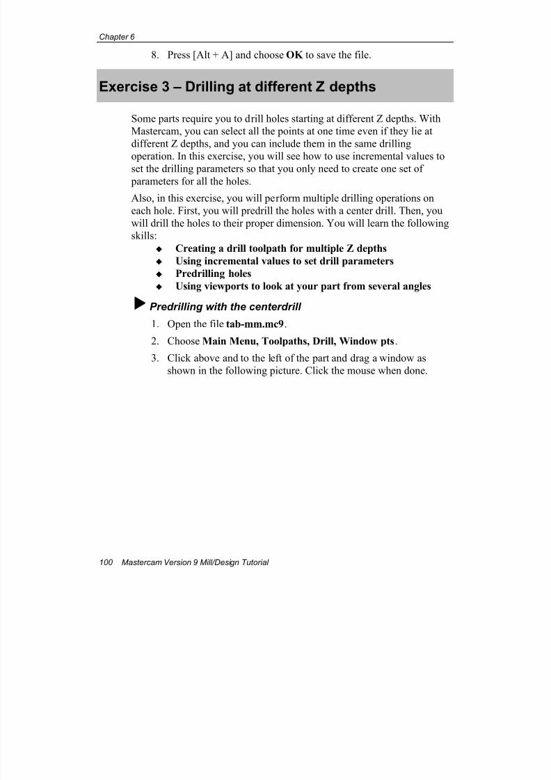
7/18/2019 V9 Mill-Design Tutorial (metric).pdf
http://slidepdf.com/reader/full/v9-mill-design-tutorial-metricpdf 112/453
Chapter 6
100 Mastercam Version 9 Mill/Design Tutorial
8. Press [Alt + A] and choose OK to save the file.
Exercise 3 – Drilling at different Z depths
Some parts require you to drill holes starting at different Z depths. With
Mastercam, you can select all the points at one time even if they lie atdifferent Z depths, and you can include them in the same drilling
operation. In this exercise, you will see how to use incremental values to
set the drilling parameters so that you only need to create one set of
parameters for all the holes.
Also, in this exercise, you will perform multiple drilling operations on
each hole. First, you will predrill the holes with a center drill. Then, you
will drill the holes to their proper dimension. You will learn the following
skills:
Creating a drill toolpath for multiple Z depths
Using incremental values to set drill parameters
Predrilling holes Using viewports to look at your part from several angles
Predrilling with the centerdrill
1. Open the file tab-mm.mc9.
2. Choose Main Menu, Toolpaths, Drill, Window pts.
3. Click above and to the left of the part and drag a window as
shown in the following picture. Click the mouse when done.
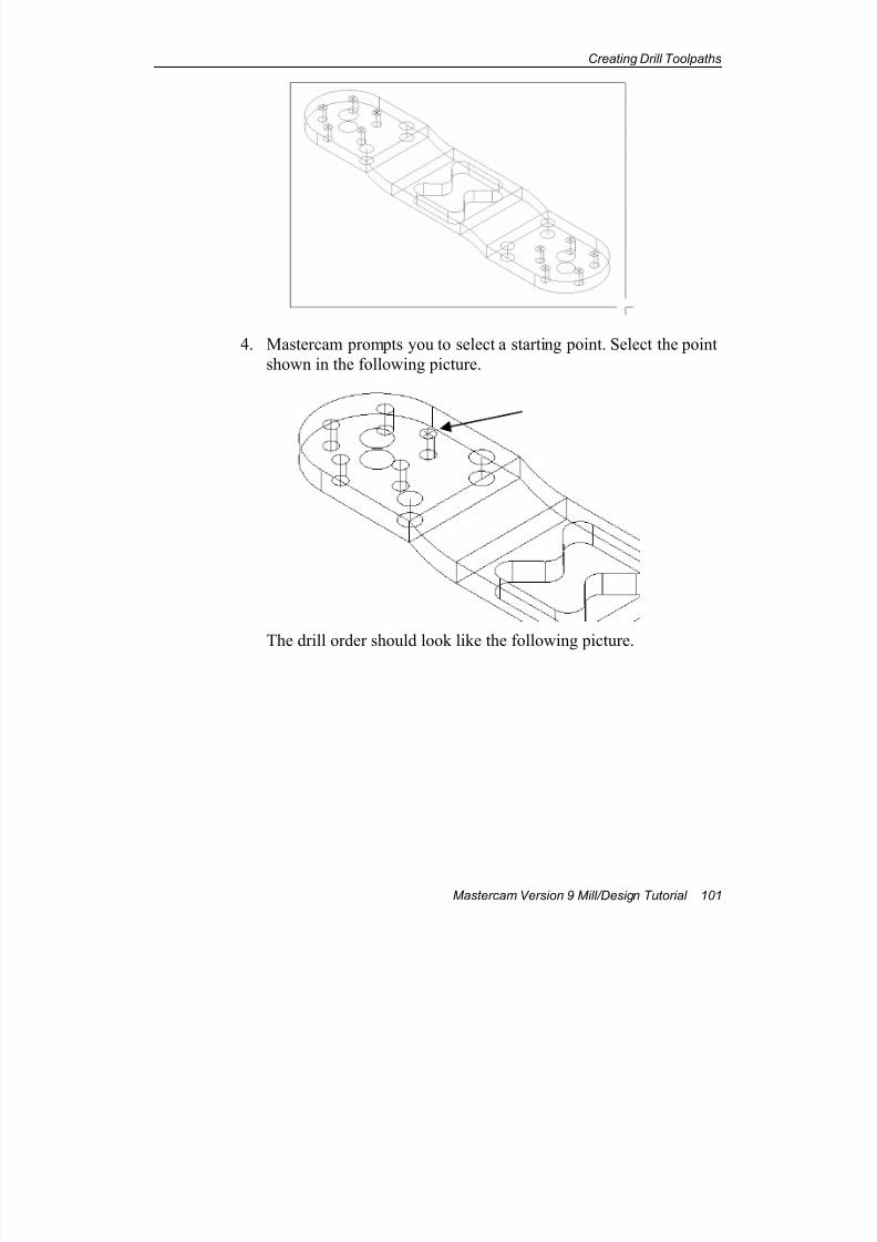
7/18/2019 V9 Mill-Design Tutorial (metric).pdf
http://slidepdf.com/reader/full/v9-mill-design-tutorial-metricpdf 113/453
Creating Drill Toolpaths
Mastercam Version 9 Mill/Design Tutorial 101
4. Mastercam prompts you to select a starting point. Select the point
shown in the following picture.
The drill order should look like the following picture.
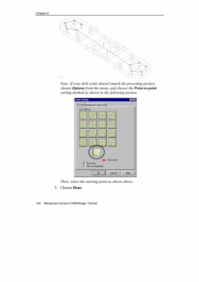
7/18/2019 V9 Mill-Design Tutorial (metric).pdf
http://slidepdf.com/reader/full/v9-mill-design-tutorial-metricpdf 114/453
Chapter 6
102 Mastercam Version 9 Mill/Design Tutorial
Note: If your drill order doesn't match the preceding picture,
choose Options from the menu, and choose the Point-to-point
sorting method as shown in the following picture.
Then, select the starting point as shown above.
5. Choose Done.
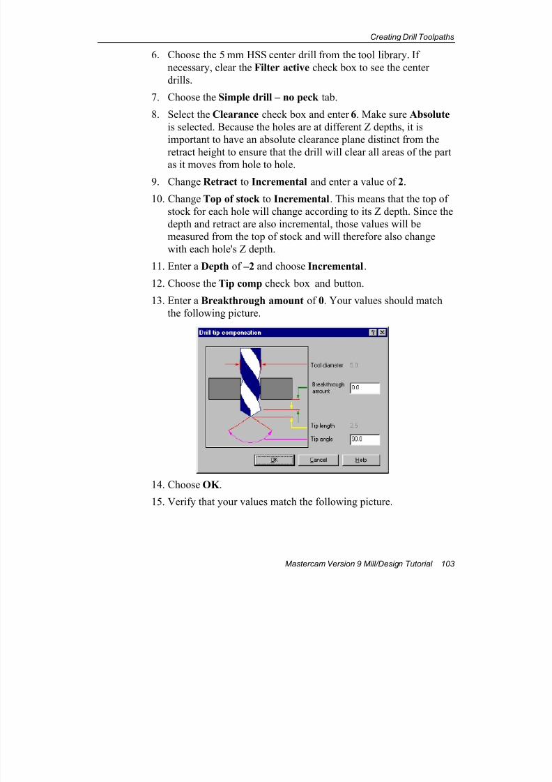
7/18/2019 V9 Mill-Design Tutorial (metric).pdf
http://slidepdf.com/reader/full/v9-mill-design-tutorial-metricpdf 115/453
Creating Drill Toolpaths
Mastercam Version 9 Mill/Design Tutorial 103
6. Choose the 5 mm HSS center drill from the tool library. If
necessary, clear the Filter active check box to see the center
drills.
7. Choose the Simple drill – no peck tab.
8. Select the Clearance check box and enter 6. Make sure Absolute
is selected. Because the holes are at different Z depths, it is
important to have an absolute clearance plane distinct from theretract height to ensure that the drill will clear all areas of the part
as it moves from hole to hole.
9. Change Retract to Incremental and enter a value of 2.
10. Change Top of stock to Incremental. This means that the top of
stock for each hole will change according to its Z depth. Since the
depth and retract are also incremental, those values will be
measured from the top of stock and will therefore also change
with each hole's Z depth.
11. Enter a Depth of –2 and choose Incremental.
12. Choose the Tip comp check box and button.
13. Enter a Breakthrough amount of 0. Your values should match
the following picture.
14. Choose OK .
15. Verify that your values match the following picture.
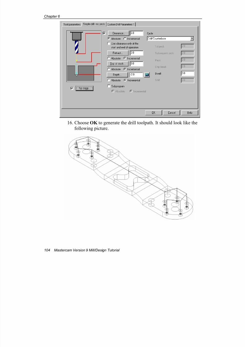
7/18/2019 V9 Mill-Design Tutorial (metric).pdf
http://slidepdf.com/reader/full/v9-mill-design-tutorial-metricpdf 116/453
Chapter 6
104 Mastercam Version 9 Mill/Design Tutorial
16. Choose OK to generate the drill toolpath. It should look like thefollowing picture.
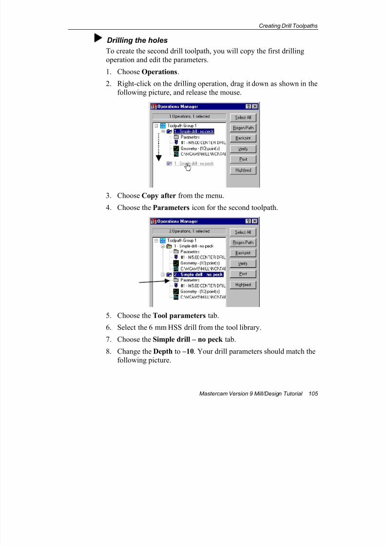
7/18/2019 V9 Mill-Design Tutorial (metric).pdf
http://slidepdf.com/reader/full/v9-mill-design-tutorial-metricpdf 117/453
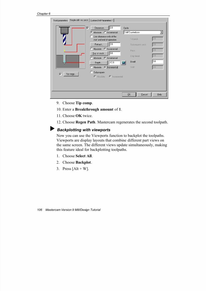
7/18/2019 V9 Mill-Design Tutorial (metric).pdf
http://slidepdf.com/reader/full/v9-mill-design-tutorial-metricpdf 118/453
Chapter 6
106 Mastercam Version 9 Mill/Design Tutorial
9. Choose Tip comp.
10. Enter a Breakthrough amount of 1.
11. Choose OK twice.
12. Choose Regen Path. Mastercam regenerates the second toolpath.
Backplotting with viewports
Now you can use the Viewports function to backplot the toolpaths.
Viewports are display layouts that combine different part views on
the same screen. The different views update simultaneously, making
this feature ideal for backplotting toolpaths.
1. Choose Select All.
2. Choose Backplot.
3. Press [Alt + W].
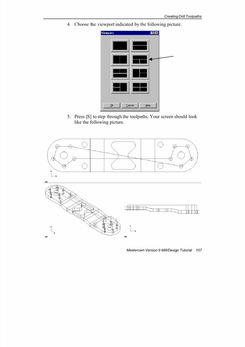
7/18/2019 V9 Mill-Design Tutorial (metric).pdf
http://slidepdf.com/reader/full/v9-mill-design-tutorial-metricpdf 119/453
Creating Drill Toolpaths
Mastercam Version 9 Mill/Design Tutorial 107
4. Choose the viewport indicated by the following picture.
5. Press [S] to step through the toolpaths. Your screen should look
like the following picture.

7/18/2019 V9 Mill-Design Tutorial (metric).pdf
http://slidepdf.com/reader/full/v9-mill-design-tutorial-metricpdf 120/453
Chapter 6
108 Mastercam Version 9 Mill/Design Tutorial
6. Press OK when Mastercam tells you the backplot is finished.
7. Choose Backup to return to the Operations Manager.
8. Choose OK to close the Operations Manager.
9. Save the file in your working folder as drilled tab.mc9.
You've now seen a number of techniques for creating 2D geometry and
toolpaths. The next chapter introduces you to creating 3D geometry andtoolpaths.
EOC
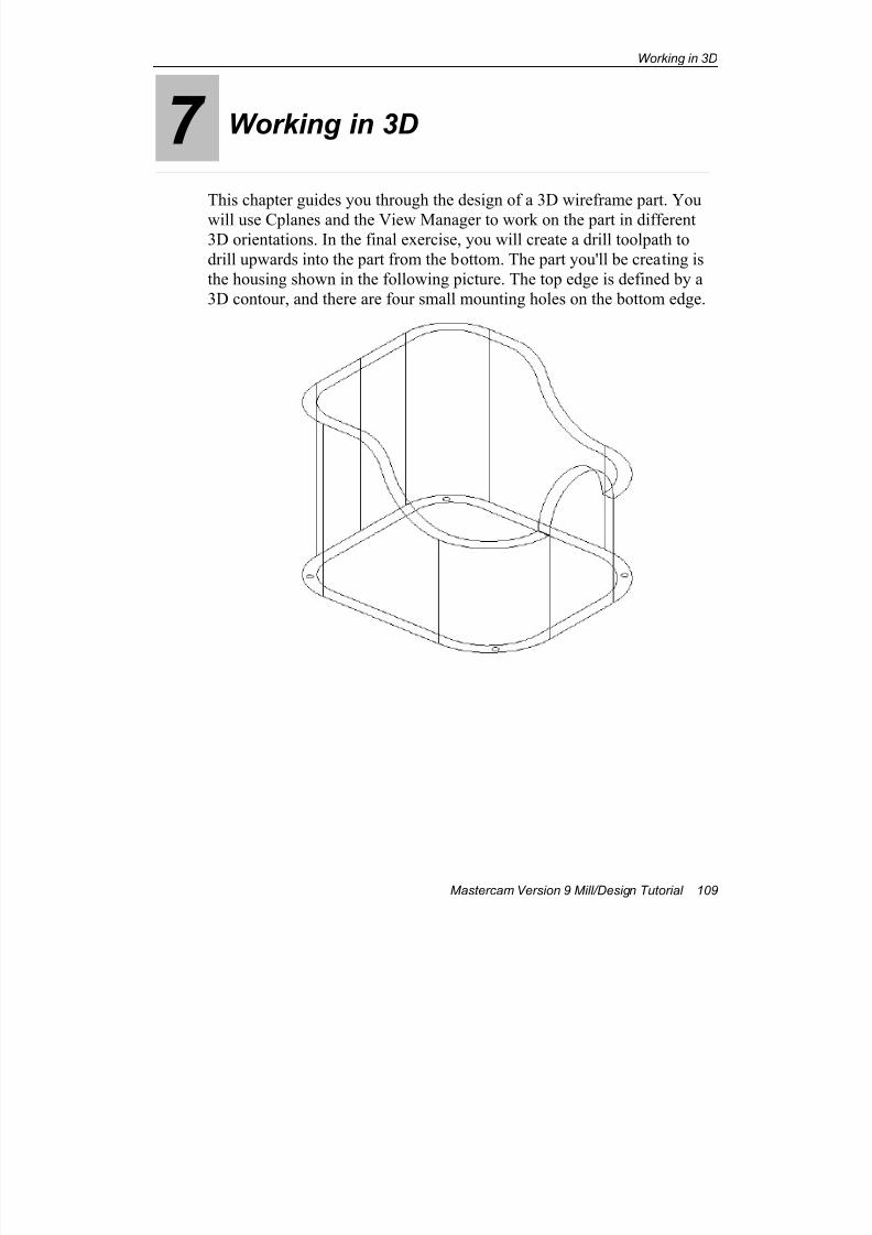
7/18/2019 V9 Mill-Design Tutorial (metric).pdf
http://slidepdf.com/reader/full/v9-mill-design-tutorial-metricpdf 121/453
Working in 3D
Mastercam Version 9 Mill/Design Tutorial 109
7 Working in 3D
This chapter guides you through the design of a 3D wireframe part. You
will use Cplanes and the View Manager to work on the part in different3D orientations. In the final exercise, you will create a drill toolpath to
drill upwards into the part from the bottom. The part you'll be creating is
the housing shown in the following picture. The top edge is defined by a
3D contour, and there are four small mounting holes on the bottom edge.
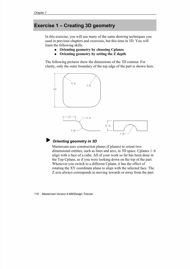
7/18/2019 V9 Mill-Design Tutorial (metric).pdf
http://slidepdf.com/reader/full/v9-mill-design-tutorial-metricpdf 122/453
Chapter 7
110 Mastercam Version 9 Mill/Design Tutorial
Exercise 1 – Creating 3D geometry
In this exercise, you will use many of the same drawing techniques you
used in previous chapters and exercises, but this time in 3D. You will
learn the following skills. Orienting geometry by choosing Cplanes
Orienting geometry by setting the Z depth
The following pictures show the dimensions of the 3D contour. For
clarity, only the outer boundary of the top edge of the part is shown here.
Orienting geometry in 3DMastercam uses construction planes (Cplanes) to orient two-
dimensional entities, such as lines and arcs, in 3D space. Cplanes 1–6
align with a face of a cube. All of your work so far has been done in
the Top Cplane, as if you were looking down on the top of the part.
Whenever you switch to a different Cplane, it has the effect of
rotating the XY coordinate plane to align with the selected face. The
Z axis always corresponds to moving towards or away from the part.
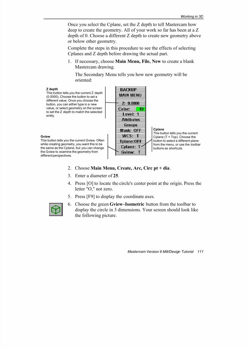
7/18/2019 V9 Mill-Design Tutorial (metric).pdf
http://slidepdf.com/reader/full/v9-mill-design-tutorial-metricpdf 123/453
Working in 3D
Mastercam Version 9 Mill/Design Tutorial 111
Once you select the Cplane, set the Z depth to tell Mastercam how
deep to create the geometry. All of your work so far has been at a Z
depth of 0. Choose a different Z depth to create new geometry above
or below other geometry.
Complete the steps in this procedure to see the effects of selecting
Cplanes and Z depth before drawing the actual part.
1. If necessary, choose Main Menu, File, New to create a blankMastercam drawing.
The Secondary Menu tells you how new geometry will be
oriented:
2. Choose Main Menu, Create, Arc, Circ pt + dia.
3. Enter a diameter of 25.
4. Press [O] to locate the circle's center point at the origin. Press theletter "O," not zero.
5. Press [F9] to display the coordinate axes.
6. Choose the green Gview–Isometric button from the toolbar to
display the circle in 3 dimensions. Your screen should look like
the following picture.
Z depth
This button tells you the current Z depth
(0.0000). Choose the button to set a
different value. Once you choose the
button, you can either type in a new
value, or select geometry on the screen
to set the Z depth to match the selectedentity.
Cplane
This button tells you the current
Cplane (T = Top). Choose the
button to select a different planefrom the menu, or use the toolbar
buttons as shortcuts.
Gview
This button tells you the current Gview. Oftenwhile creating geometry, you want this to be
the same as the Cplane, but you can change
the Gview to examine the geometry from
different perspectives.
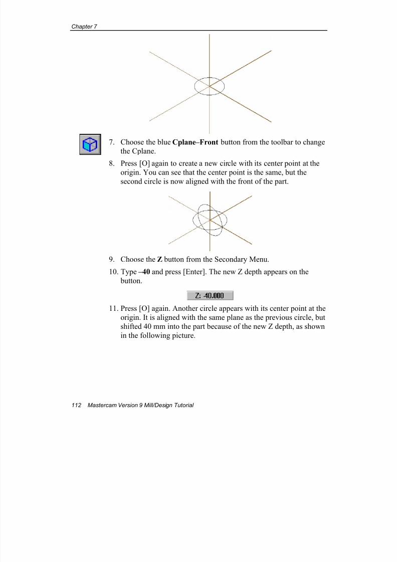
7/18/2019 V9 Mill-Design Tutorial (metric).pdf
http://slidepdf.com/reader/full/v9-mill-design-tutorial-metricpdf 124/453
Chapter 7
112 Mastercam Version 9 Mill/Design Tutorial
7. Choose the blue Cplane–Front button from the toolbar to change
the Cplane.
8. Press [O] again to create a new circle with its center point at the
origin. You can see that the center point is the same, but the
second circle is now aligned with the front of the part.
9. Choose the Z button from the Secondary Menu.
10. Type –40 and press [Enter]. The new Z depth appears on the
button.
11. Press [O] again. Another circle appears with its center point at the
origin. It is aligned with the same plane as the previous circle, but
shifted 40 mm into the part because of the new Z depth, as shown
in the following picture.

7/18/2019 V9 Mill-Design Tutorial (metric).pdf
http://slidepdf.com/reader/full/v9-mill-design-tutorial-metricpdf 125/453
Working in 3D
Mastercam Version 9 Mill/Design Tutorial 113
12. Choose the blue Cplane–Side button from the toolbar to align
new geometry with the left side of the part.
13. Choose Z and enter 75.
14. Choose Backup, Circ pt + dia.
15. Press [Enter] to accept the diameter of 25.
16. Enter the coordinates X–25,Y10 to create the first circle.
17. Enter the coordinate X25 to create a second circle. The newcircles are aligned with the left face of the part, 75 mm in front of
the system origin, as shown in the following picture.
18. Choose Main Menu, File, New to clear the geometry from the
screen. Choose No when prompted to save the file.
Note: After choosing File, New , the Cplane and Gview are reset
to Top and the Z depth is reset to 0.
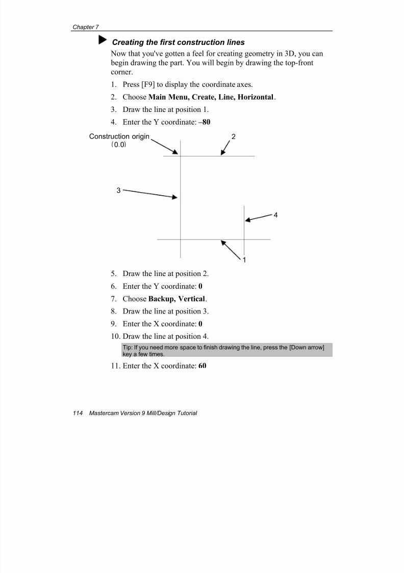
7/18/2019 V9 Mill-Design Tutorial (metric).pdf
http://slidepdf.com/reader/full/v9-mill-design-tutorial-metricpdf 126/453
Chapter 7
114 Mastercam Version 9 Mill/Design Tutorial
Creating the first construction lines
Now that you've gotten a feel for creating geometry in 3D, you can
begin drawing the part. You will begin by drawing the top-front
corner.
1. Press [F9] to display the coordinate axes.
2. Choose Main Menu, Create, Line, Horizontal.3. Draw the line at position 1.
4. Enter the Y coordinate: –80
5. Draw the line at position 2.
6. Enter the Y coordinate: 0
7. Choose Backup, Vertical.8. Draw the line at position 3.
9. Enter the X coordinate: 0
10. Draw the line at position 4.
Tip: If you need more space to finish drawing the line, press the [Down arrow]key a few times.
11. Enter the X coordinate: 60
1
2
3
4
Construction origin0 0
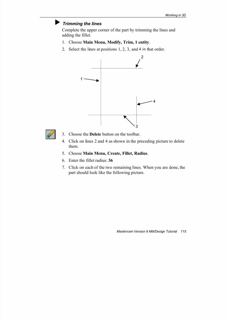
7/18/2019 V9 Mill-Design Tutorial (metric).pdf
http://slidepdf.com/reader/full/v9-mill-design-tutorial-metricpdf 127/453
Working in 3D
Mastercam Version 9 Mill/Design Tutorial 115
Trimming the lines
Complete the upper corner of the part by trimming the lines and
adding the fillet.
1. Choose Main Menu, Modify, Trim, 1 entity.
2. Select the lines at positions 1, 2, 3, and 4 in that order.
3. Choose the Delete button on the toolbar.
4. Click on lines 2 and 4 as shown in the preceding picture to delete
them.
5. Choose Main Menu, Create, Fillet, Radius.
6. Enter the fillet radius: 36
7. Click on each of the two remaining lines. When you are done, the part should look like the following picture.
3
1
4
2

7/18/2019 V9 Mill-Design Tutorial (metric).pdf
http://slidepdf.com/reader/full/v9-mill-design-tutorial-metricpdf 128/453
Chapter 7
116 Mastercam Version 9 Mill/Design Tutorial
Drawing the front face
In this procedure, you will draw the curve on the front face of the
part.
1. Set the Gview to Isometric.
2. Set the Cplane to Front.
3. Choose the Z button.
4. Select the line shown in the following picture to set the Z depth to80.
5. Choose Main Menu, Create, Arc, Tangent, 1 entity.
6. Select the line again at position 1.

7/18/2019 V9 Mill-Design Tutorial (metric).pdf
http://slidepdf.com/reader/full/v9-mill-design-tutorial-metricpdf 129/453
Working in 3D
Mastercam Version 9 Mill/Design Tutorial 117
7. Choose the tangent point by selecting the endpoint at position 2.
8. Enter the radius of 24.
9. Select the arc shown in the
picture at right.
10. Choose Main Menu, Create, Line, Horizontal.
11. Draw the line as shown in the following picture.
1
2
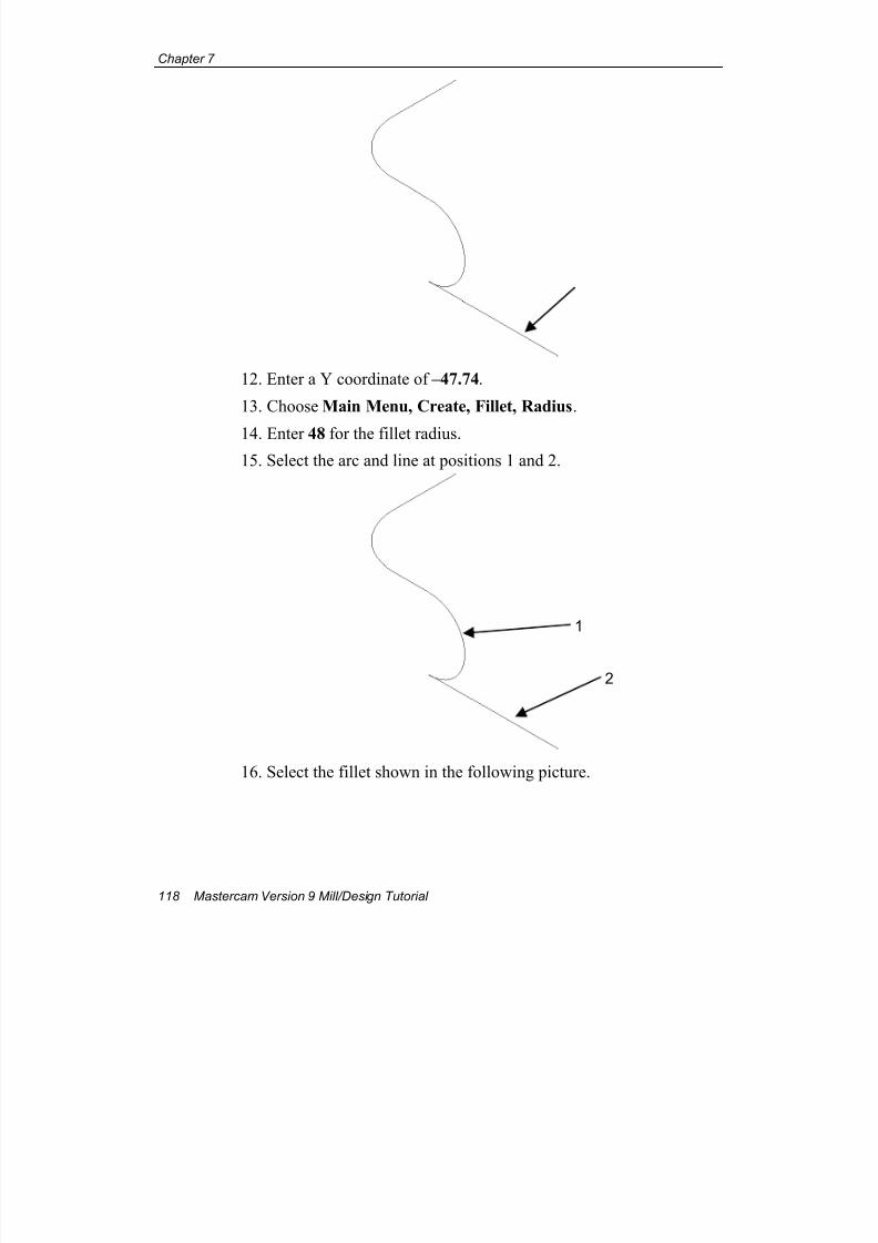
7/18/2019 V9 Mill-Design Tutorial (metric).pdf
http://slidepdf.com/reader/full/v9-mill-design-tutorial-metricpdf 130/453
Chapter 7
118 Mastercam Version 9 Mill/Design Tutorial
12. Enter a Y coordinate of –47.74.
13. Choose Main Menu, Create, Fillet, Radius.
14. Enter 48 for the fillet radius.15. Select the arc and line at positions 1 and 2.
16. Select the fillet shown in the following picture.
1
2
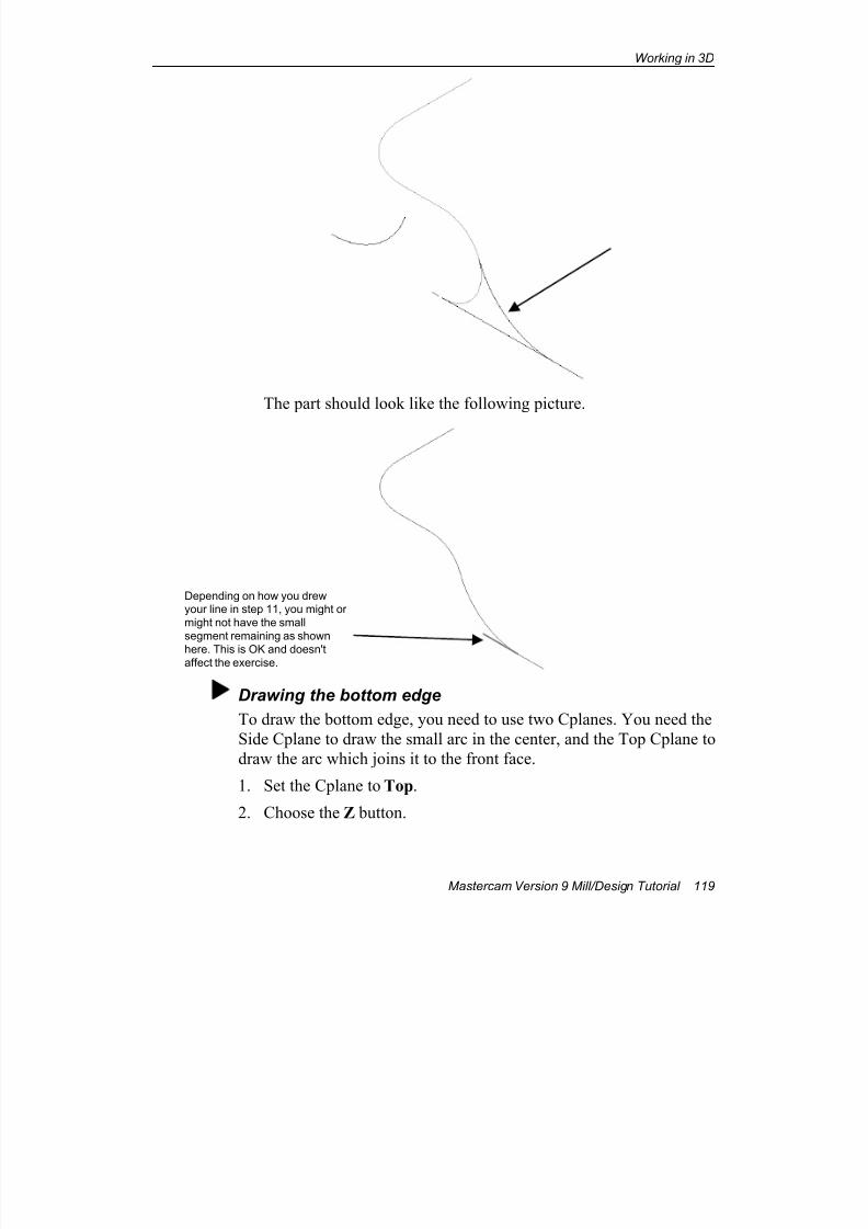
7/18/2019 V9 Mill-Design Tutorial (metric).pdf
http://slidepdf.com/reader/full/v9-mill-design-tutorial-metricpdf 131/453
Working in 3D
Mastercam Version 9 Mill/Design Tutorial 119
The part should look like the following picture.
Drawing the bottom edge
To draw the bottom edge, you need to use two Cplanes. You need the
Side Cplane to draw the small arc in the center, and the Top Cplane to
draw the arc which joins it to the front face.
1. Set the Cplane to Top.
2. Choose the Z button.
Depending on how you drewyour line in step 11, you might or
might not have the small
segment remaining as shown
here. This is OK and doesn'taffect the exercise.
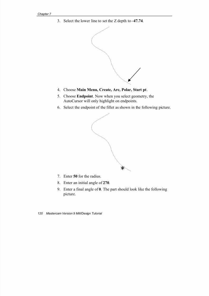
7/18/2019 V9 Mill-Design Tutorial (metric).pdf
http://slidepdf.com/reader/full/v9-mill-design-tutorial-metricpdf 132/453
Chapter 7
120 Mastercam Version 9 Mill/Design Tutorial
3. Select the lower line to set the Z depth to –47.74.
4. Choose Main Menu, Create, Arc, Polar, Start pt.
5. Choose Endpoint. Now when you select geometry, the
AutoCursor will only highlight on endpoints.
6. Select the endpoint of the fillet as shown in the following picture.
7. Enter 50 for the radius.
8. Enter an initial angle of 270.
9. Enter a final angle of 0. The part should look like the following
picture.
E
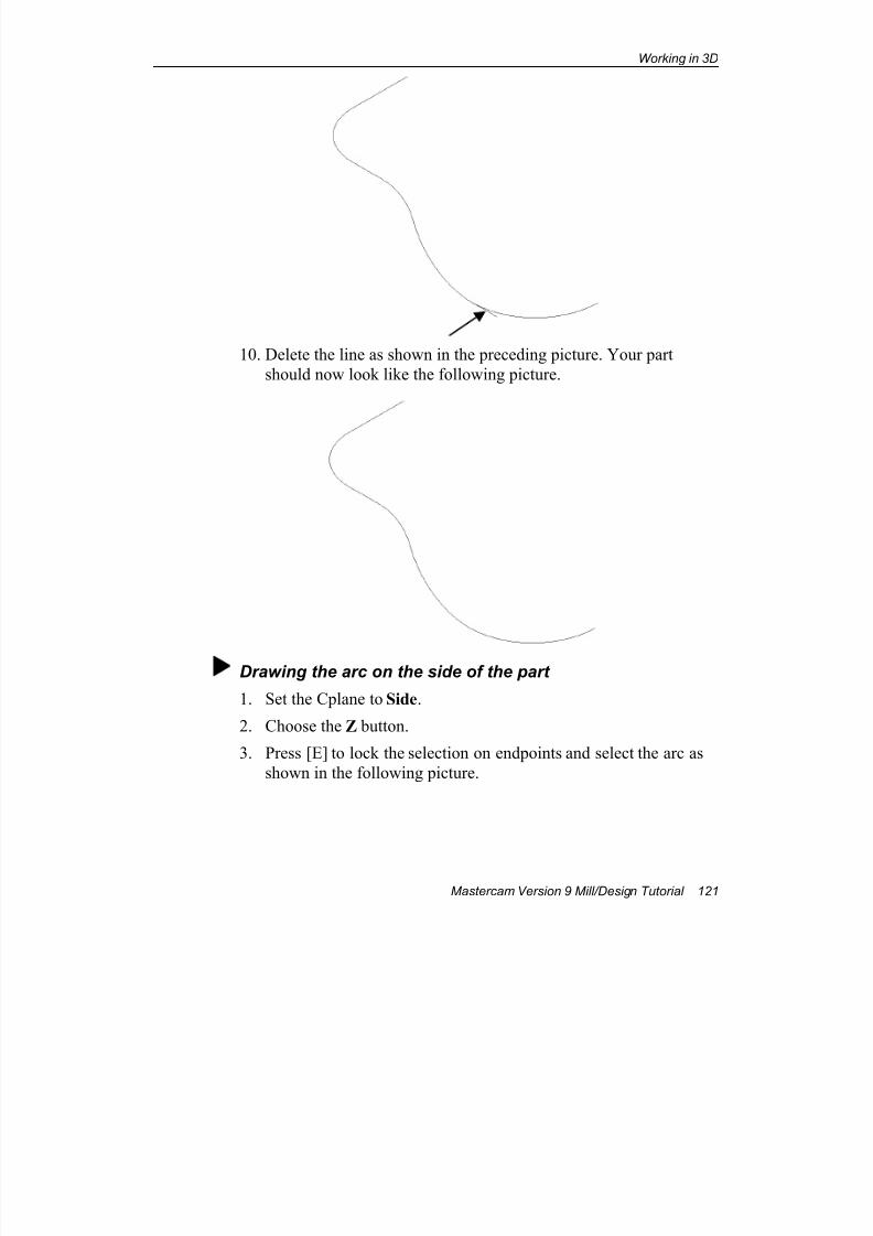
7/18/2019 V9 Mill-Design Tutorial (metric).pdf
http://slidepdf.com/reader/full/v9-mill-design-tutorial-metricpdf 133/453
Working in 3D
Mastercam Version 9 Mill/Design Tutorial 121
10. Delete the line as shown in the preceding picture. Your part
should now look like the following picture.
Drawing the arc on the side of the part
1. Set the Cplane to Side.
2. Choose the Z button.
3. Press [E] to lock the selection on endpoints and select the arc as
shown in the following picture.
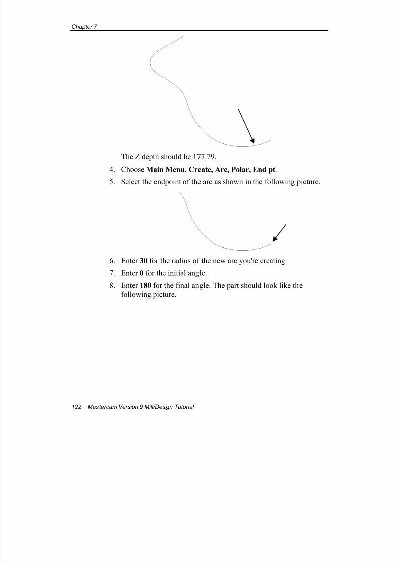
7/18/2019 V9 Mill-Design Tutorial (metric).pdf
http://slidepdf.com/reader/full/v9-mill-design-tutorial-metricpdf 134/453
Chapter 7
122 Mastercam Version 9 Mill/Design Tutorial
The Z depth should be 177.79.
4. Choose Main Menu, Create, Arc, Polar, End pt.
5. Select the endpoint of the arc as shown in the following picture.
6. Enter 30 for the radius of the new arc you're creating.
7. Enter 0 for the initial angle.
8. Enter 180 for the final angle. The part should look like the
following picture.
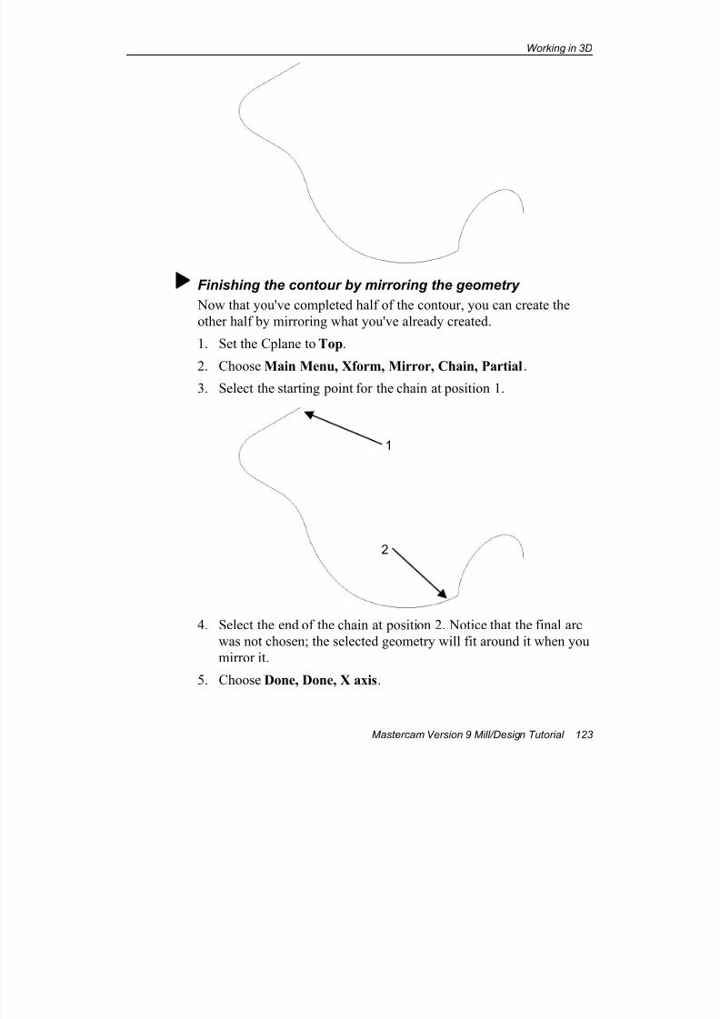
7/18/2019 V9 Mill-Design Tutorial (metric).pdf
http://slidepdf.com/reader/full/v9-mill-design-tutorial-metricpdf 135/453
Working in 3D
Mastercam Version 9 Mill/Design Tutorial 123
Finishing the contour by mirroring the geometry
Now that you've completed half of the contour, you can create the
other half by mirroring what you've already created.
1. Set the Cplane to Top.
2. Choose Main Menu, Xform, Mirror, Chain, Partial.
3. Select the starting point for the chain at position 1.
4. Select the end of the chain at position 2. Notice that the final arc
was not chosen; the selected geometry will fit around it when you
mirror it.
5. Choose Done, Done, X axis.
1
2
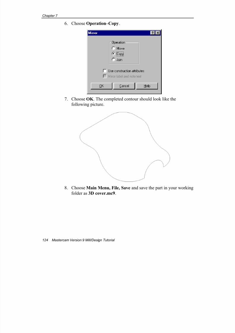
7/18/2019 V9 Mill-Design Tutorial (metric).pdf
http://slidepdf.com/reader/full/v9-mill-design-tutorial-metricpdf 136/453
Chapter 7
124 Mastercam Version 9 Mill/Design Tutorial
6. Choose Operation–Copy.
7. Choose OK . The completed contour should look like the
following picture.
8. Choose Main Menu, File, Save and save the part in your working
folder as 3D cover.mc9.
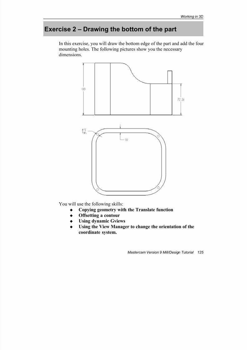
7/18/2019 V9 Mill-Design Tutorial (metric).pdf
http://slidepdf.com/reader/full/v9-mill-design-tutorial-metricpdf 137/453
Working in 3D
Mastercam Version 9 Mill/Design Tutorial 125
Exercise 2 – Drawing the bottom of the part
In this exercise, you will draw the bottom edge of the part and add the four
mounting holes. The following pictures show you the necessary
dimensions.
You will use the following skills:
Copying geometry with the Translate function
Offsetting a contour
Using dynamic Gviews
Using the View Manager to change the orientation of the
coordinate system.
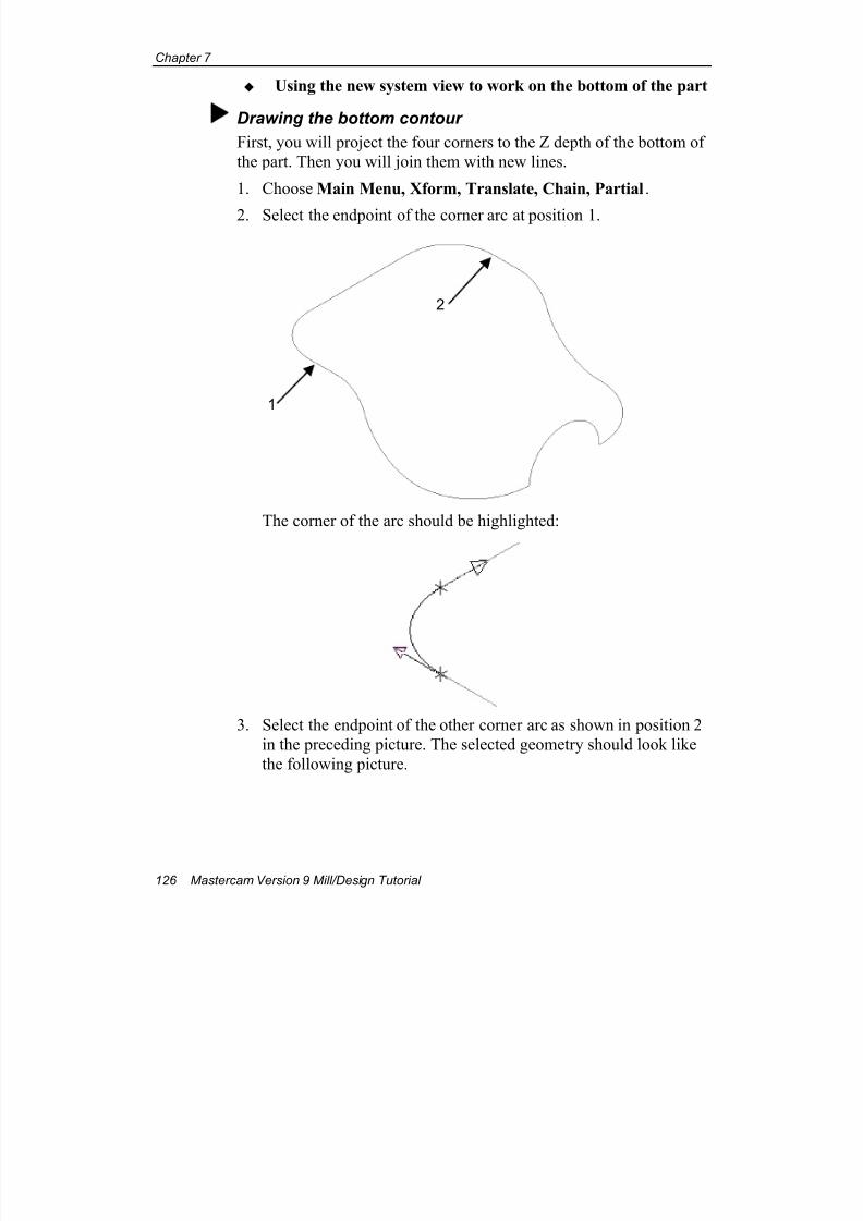
7/18/2019 V9 Mill-Design Tutorial (metric).pdf
http://slidepdf.com/reader/full/v9-mill-design-tutorial-metricpdf 138/453
Chapter 7
126 Mastercam Version 9 Mill/Design Tutorial
Using the new system view to work on the bottom of the part
Drawing the bottom contour
First, you will project the four corners to the Z depth of the bottom of
the part. Then you will join them with new lines.
1. Choose Main Menu, Xform, Translate, Chain, Partial.
2. Select the endpoint of the corner arc at position 1.
The corner of the arc should be highlighted:
3. Select the endpoint of the other corner arc as shown in position 2
in the preceding picture. The selected geometry should look like
the following picture.
1
2
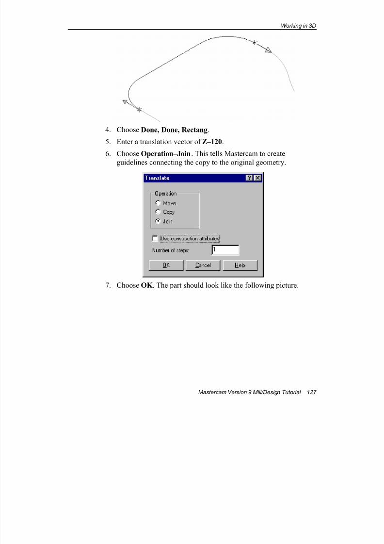
7/18/2019 V9 Mill-Design Tutorial (metric).pdf
http://slidepdf.com/reader/full/v9-mill-design-tutorial-metricpdf 139/453
Working in 3D
Mastercam Version 9 Mill/Design Tutorial 127
4. Choose Done, Done, Rectang.
5. Enter a translation vector of Z–120.
6. Choose Operation–Join. This tells Mastercam to create
guidelines connecting the copy to the original geometry.
7. Choose OK . The part should look like the following picture.
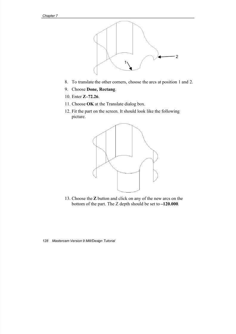
7/18/2019 V9 Mill-Design Tutorial (metric).pdf
http://slidepdf.com/reader/full/v9-mill-design-tutorial-metricpdf 140/453
Chapter 7
128 Mastercam Version 9 Mill/Design Tutorial
8. To translate the other corners, choose the arcs at position 1 and 2.
9. Choose Done, Rectang.
10. Enter Z–72.26.
11. Choose OK at the Translate dialog box.
12. Fit the part on the screen. It should look like the following
picture.
13. Choose the Z button and click on any of the new arcs on the
bottom of the part. The Z depth should be set to –120.000.
12
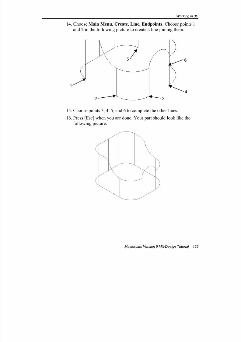
7/18/2019 V9 Mill-Design Tutorial (metric).pdf
http://slidepdf.com/reader/full/v9-mill-design-tutorial-metricpdf 141/453
Working in 3D
Mastercam Version 9 Mill/Design Tutorial 129
14. Choose Main Menu, Create, Line, Endpoints. Choose points 1
and 2 in the following picture to create a line joining them.
15. Choose points 3, 4, 5, and 6 to complete the other lines.
16. Press [Esc] when you are done. Your part should look like thefollowing picture.
1
2
65
4
3
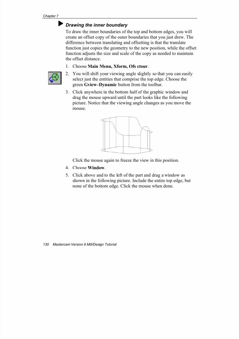
7/18/2019 V9 Mill-Design Tutorial (metric).pdf
http://slidepdf.com/reader/full/v9-mill-design-tutorial-metricpdf 142/453
Chapter 7
130 Mastercam Version 9 Mill/Design Tutorial
Drawing the inner boundary
To draw the inner boundaries of the top and bottom edges, you will
create an offset copy of the outer boundaries that you just drew. The
difference between translating and offsetting is that the translate
function just copies the geometry to the new position, while the offset
function adjusts the size and scale of the copy as needed to maintain
the offset distance.1. Choose Main Menu, Xform, Ofs ctour.
2. You will shift your viewing angle slightly so that you can easily
select just the entities that comprise the top edge. Choose the
green Gview–Dynamic button from the toolbar.
3. Click anywhere in the bottom half of the graphic window and
drag the mouse upward until the part looks like the following
picture. Notice that the viewing angle changes as you move the
mouse.
Click the mouse again to freeze the view in this position.
4. Choose Window.
5. Click above and to the left of the part and drag a window as
shown in the following picture. Include the entire top edge, but
none of the bottom edge. Click the mouse when done.

7/18/2019 V9 Mill-Design Tutorial (metric).pdf
http://slidepdf.com/reader/full/v9-mill-design-tutorial-metricpdf 143/453
Working in 3D
Mastercam Version 9 Mill/Design Tutorial 131
6. When prompted to enter a search point, click near the position
indicated in the preceding picture. The entire top edge should
highlight.
7. Choose Done.
8. Choose Operation–Copy.
9. Choose Right for Offset direction.10. Enter a Distance of 10. Your selections should match the
following picture.
search point
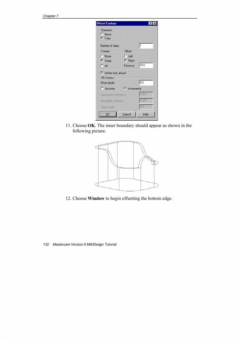
7/18/2019 V9 Mill-Design Tutorial (metric).pdf
http://slidepdf.com/reader/full/v9-mill-design-tutorial-metricpdf 144/453
Chapter 7
132 Mastercam Version 9 Mill/Design Tutorial
11. Choose OK . The inner boundary should appear as shown in the
following picture.
12. Choose Window to begin offsetting the bottom edge.
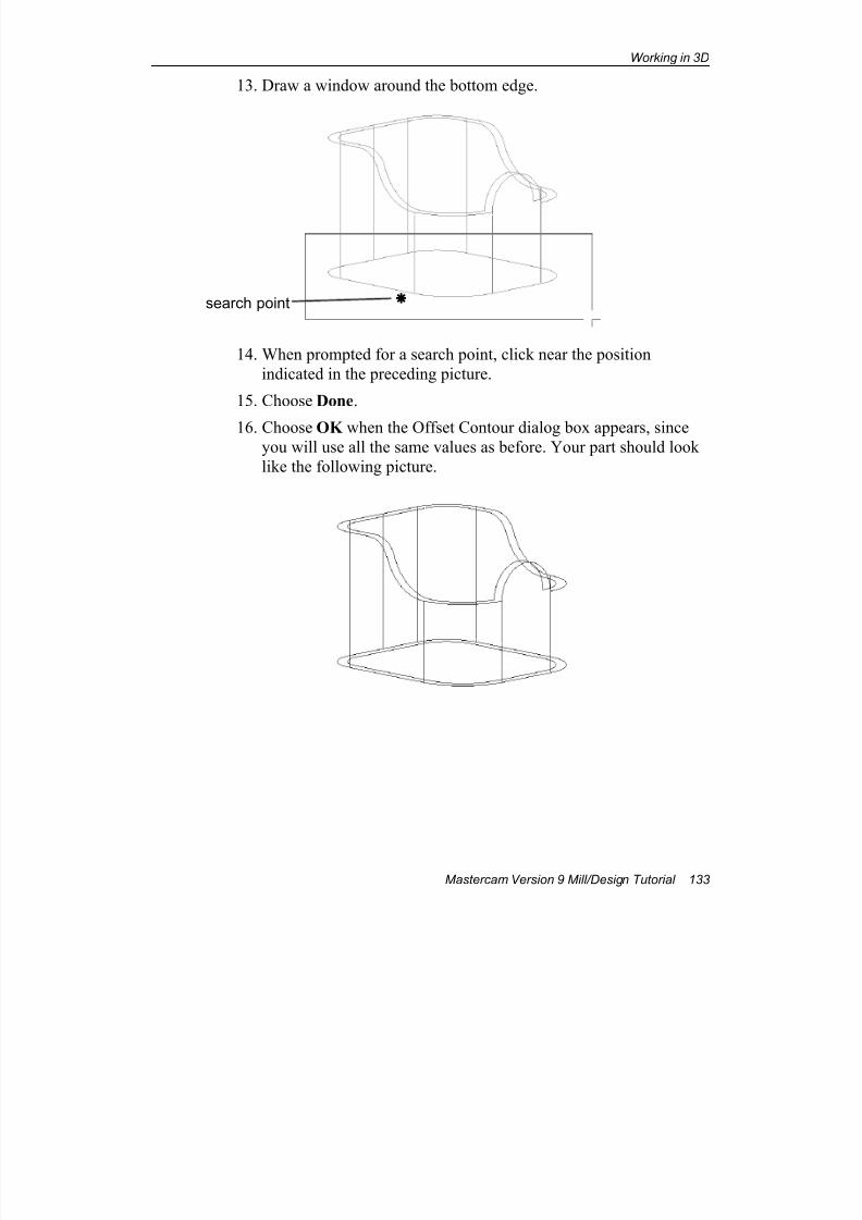
7/18/2019 V9 Mill-Design Tutorial (metric).pdf
http://slidepdf.com/reader/full/v9-mill-design-tutorial-metricpdf 145/453
Working in 3D
Mastercam Version 9 Mill/Design Tutorial 133
13. Draw a window around the bottom edge.
14. When prompted for a search point, click near the position
indicated in the preceding picture.
15. Choose Done.
16. Choose OK when the Offset Contour dialog box appears, sinceyou will use all the same values as before. Your part should look
like the following picture.
search point

7/18/2019 V9 Mill-Design Tutorial (metric).pdf
http://slidepdf.com/reader/full/v9-mill-design-tutorial-metricpdf 146/453
Chapter 7
134 Mastercam Version 9 Mill/Design Tutorial
Switching the system view
Now you need to create the holes on the bottom of the part. In this
procedure, you will switch the system view from Top to Bottom so
that you can work more easily on the bottom of the part. Switching
the system view means that the entire coordinate system shifts; even
the orientation of the Cplanes and Gviews changes so that they are
relative to the new system view.1. Switch to Gview–Isometric to cancel the dynamic Gview you've
been working in.
2. Choose the WCS button from the Secondary Menu. The View
Manager dialog box displays.
3. Under System Views Display, choose All.
4. Activate System View–Bottom by selecting the WCS column for
V# 4 as shown in the following picture.
5. Select the Update graphics view when changing WCS check
box. Your selections should match the following picture.
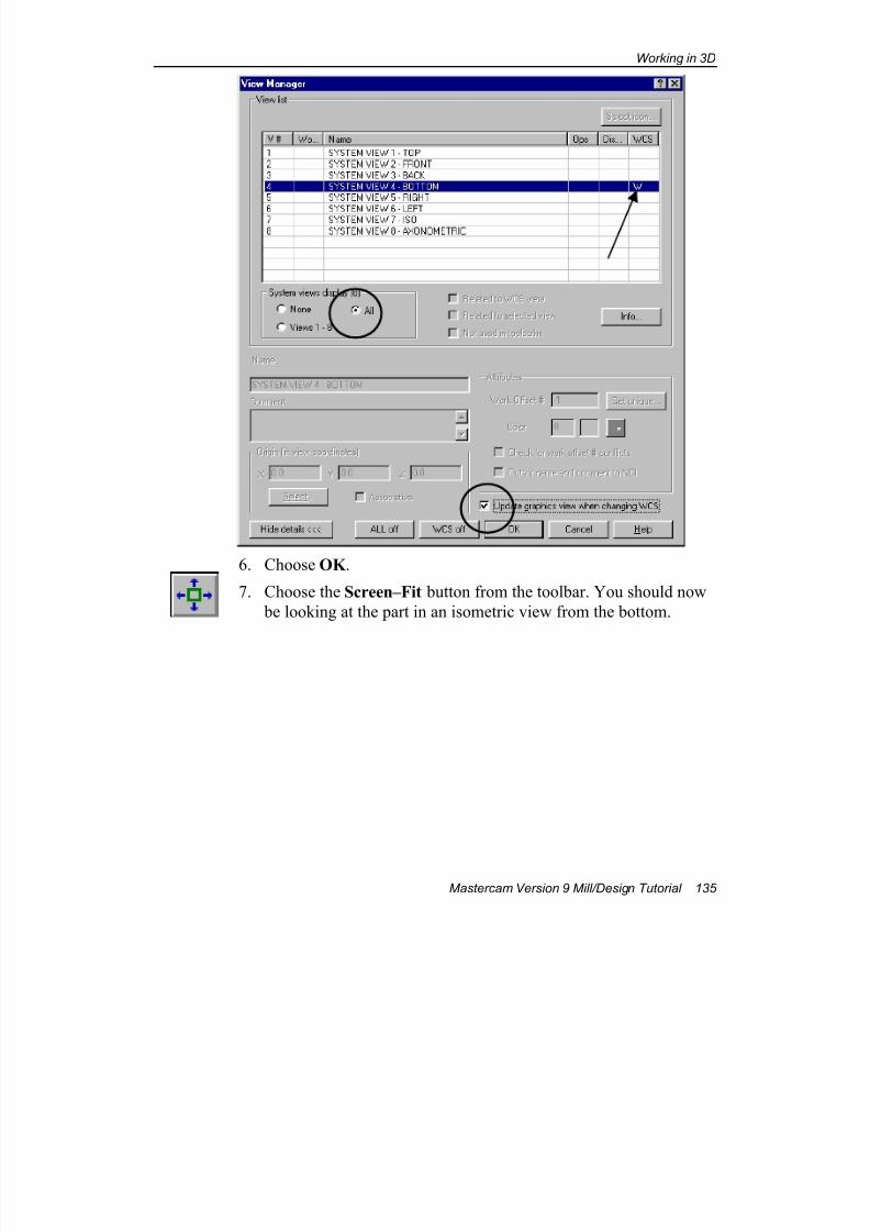
7/18/2019 V9 Mill-Design Tutorial (metric).pdf
http://slidepdf.com/reader/full/v9-mill-design-tutorial-metricpdf 147/453
Working in 3D
Mastercam Version 9 Mill/Design Tutorial 135
6. Choose OK .
7. Choose the Screen–Fit button from the toolbar. You should now
be looking at the part in an isometric view from the bottom.
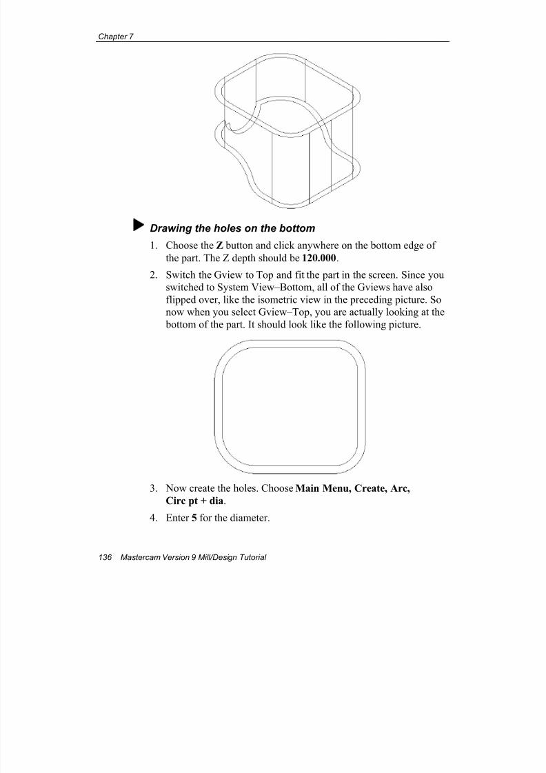
7/18/2019 V9 Mill-Design Tutorial (metric).pdf
http://slidepdf.com/reader/full/v9-mill-design-tutorial-metricpdf 148/453
Chapter 7
136 Mastercam Version 9 Mill/Design Tutorial
Drawing the holes on the bottom
1. Choose the Z button and click anywhere on the bottom edge of
the part. The Z depth should be 120.000.
2. Switch the Gview to Top and fit the part in the screen. Since you
switched to System View–Bottom, all of the Gviews have also
flipped over, like the isometric view in the preceding picture. So
now when you select Gview–Top, you are actually looking at the
bottom of the part. It should look like the following picture.
3. Now create the holes. Choose Main Menu, Create, Arc,
Circ pt + dia.
4. Enter 5 for the diameter.
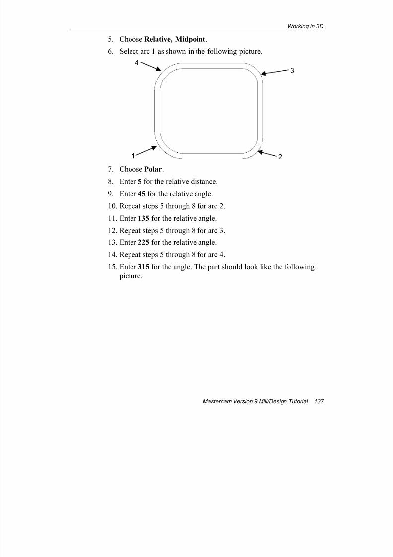
7/18/2019 V9 Mill-Design Tutorial (metric).pdf
http://slidepdf.com/reader/full/v9-mill-design-tutorial-metricpdf 149/453
Working in 3D
Mastercam Version 9 Mill/Design Tutorial 137
5. Choose Relative, Midpoint.
6. Select arc 1 as shown in the following picture.
7. Choose Polar.
8. Enter 5 for the relative distance.
9. Enter 45 for the relative angle.10. Repeat steps 5 through 8 for arc 2.
11. Enter 135 for the relative angle.
12. Repeat steps 5 through 8 for arc 3.
13. Enter 225 for the relative angle.
14. Repeat steps 5 through 8 for arc 4.
15. Enter 315 for the angle. The part should look like the following
picture.
1 2
43
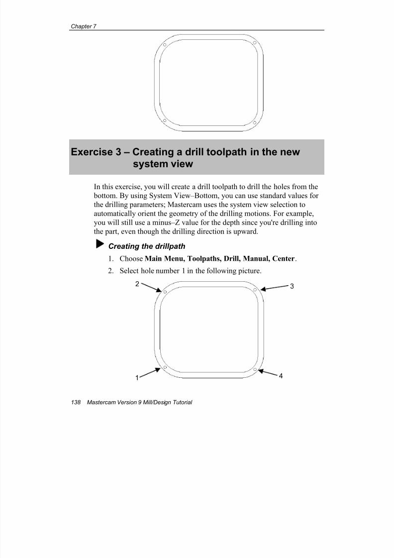
7/18/2019 V9 Mill-Design Tutorial (metric).pdf
http://slidepdf.com/reader/full/v9-mill-design-tutorial-metricpdf 150/453
Chapter 7
138 Mastercam Version 9 Mill/Design Tutorial
Exercise 3 – Creating a drill toolpath in the newsystem view
In this exercise, you will create a drill toolpath to drill the holes from the
bottom. By using System View–Bottom, you can use standard values forthe drilling parameters; Mastercam uses the system view selection to
automatically orient the geometry of the drilling motions. For example,
you will still use a minus–Z value for the depth since you're drilling into
the part, even though the drilling direction is upward.
Creating the drillpath
1. Choose Main Menu, Toolpaths, Drill, Manual, Center.
2. Select hole number 1 in the following picture.
1 4
2 3
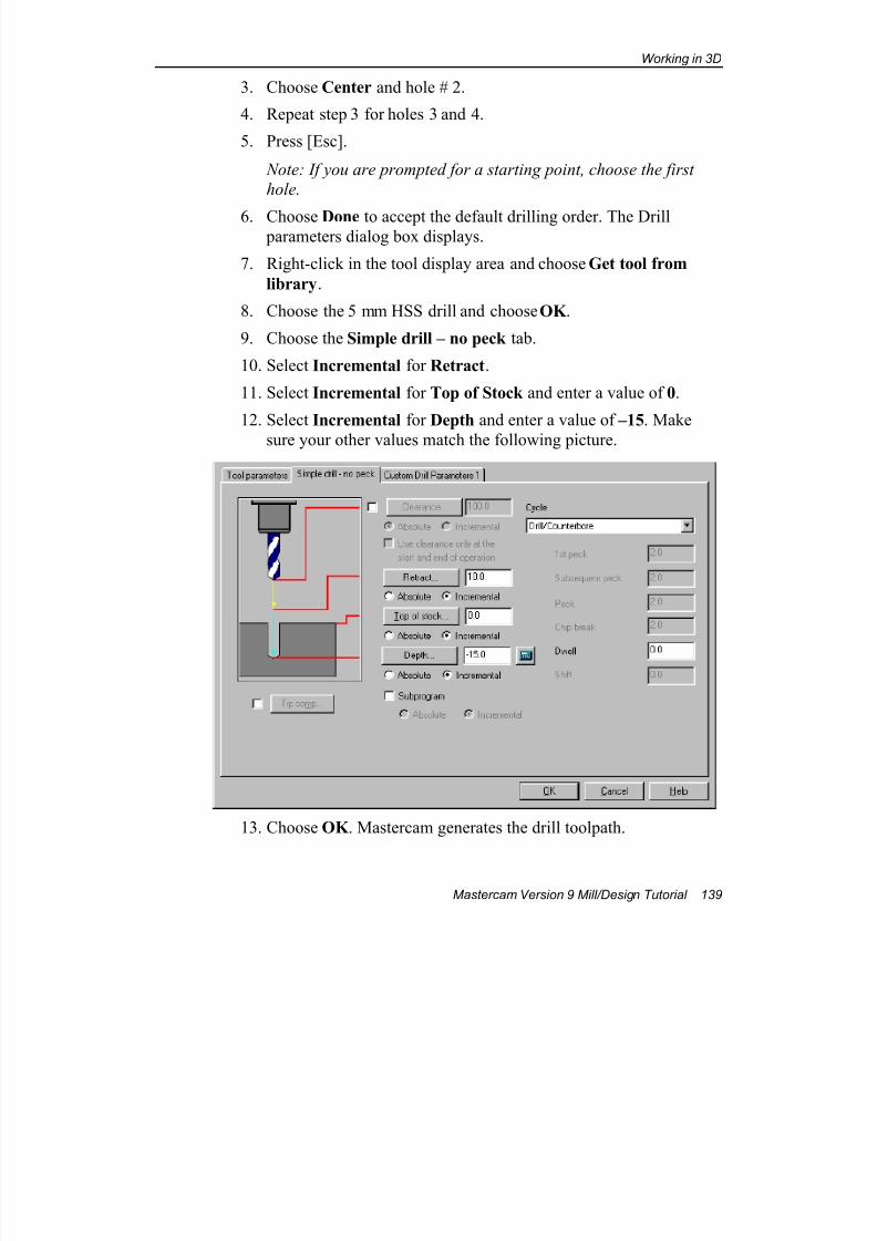
7/18/2019 V9 Mill-Design Tutorial (metric).pdf
http://slidepdf.com/reader/full/v9-mill-design-tutorial-metricpdf 151/453
Working in 3D
Mastercam Version 9 Mill/Design Tutorial 139
3. Choose Center and hole # 2.
4. Repeat step 3 for holes 3 and 4.
5. Press [Esc].
Note: If you are prompted for a starting point, choose the first
hole.
6. Choose Done to accept the default drilling order. The Drill parameters dialog box displays.
7. Right-click in the tool display area and choose Get tool from
library.
8. Choose the 5 mm HSS drill and choose OK .
9. Choose the Simple drill – no peck tab.
10. Select Incremental for Retract.
11. Select Incremental for Top of Stock and enter a value of 0.
12. Select Incremental for Depth and enter a value of –15. Make
sure your other values match the following picture.
13. Choose OK . Mastercam generates the drill toolpath.
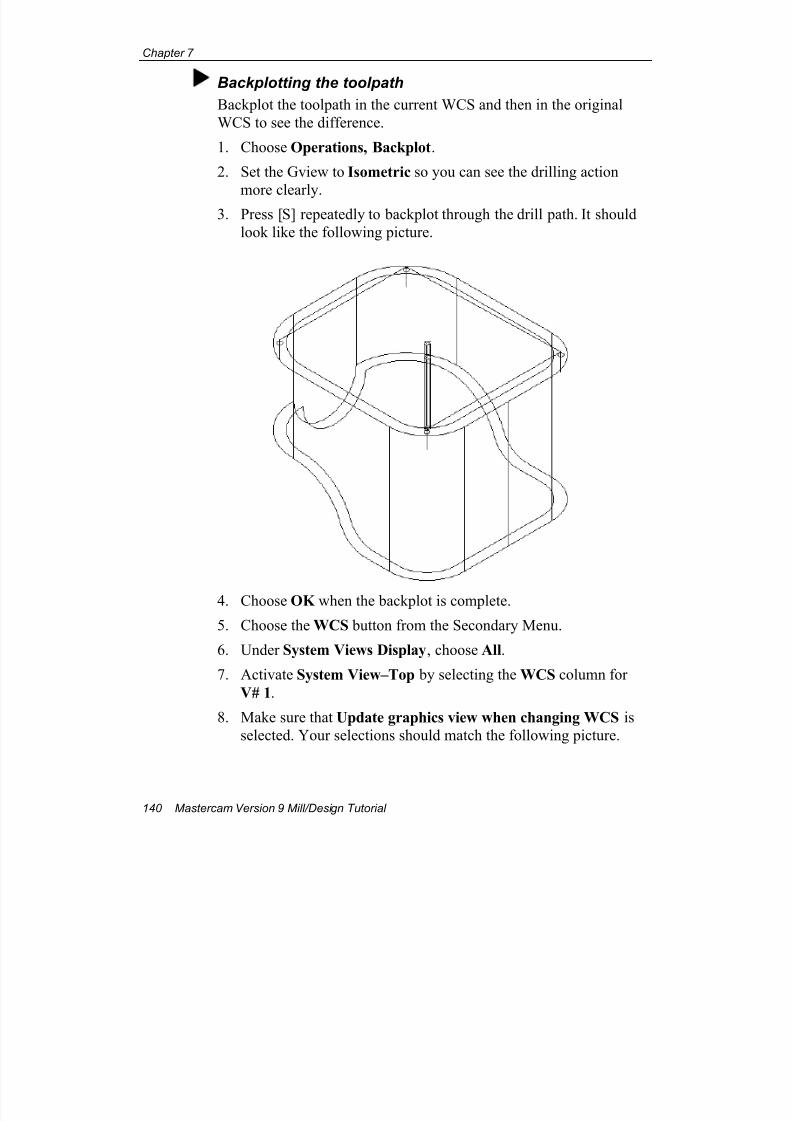
7/18/2019 V9 Mill-Design Tutorial (metric).pdf
http://slidepdf.com/reader/full/v9-mill-design-tutorial-metricpdf 152/453
Chapter 7
140 Mastercam Version 9 Mill/Design Tutorial
Backplotting the toolpath
Backplot the toolpath in the current WCS and then in the original
WCS to see the difference.
1. Choose Operations, Backplot.
2. Set the Gview to Isometric so you can see the drilling action
more clearly.3. Press [S] repeatedly to backplot through the drill path. It should
look like the following picture.
4. Choose OK when the backplot is complete.
5. Choose the WCS button from the Secondary Menu.
6. Under System Views Display, choose All.
7. Activate System View–Top by selecting the WCS column for
V# 1.
8. Make sure that Update graphics view when changing WCS is
selected. Your selections should match the following picture.
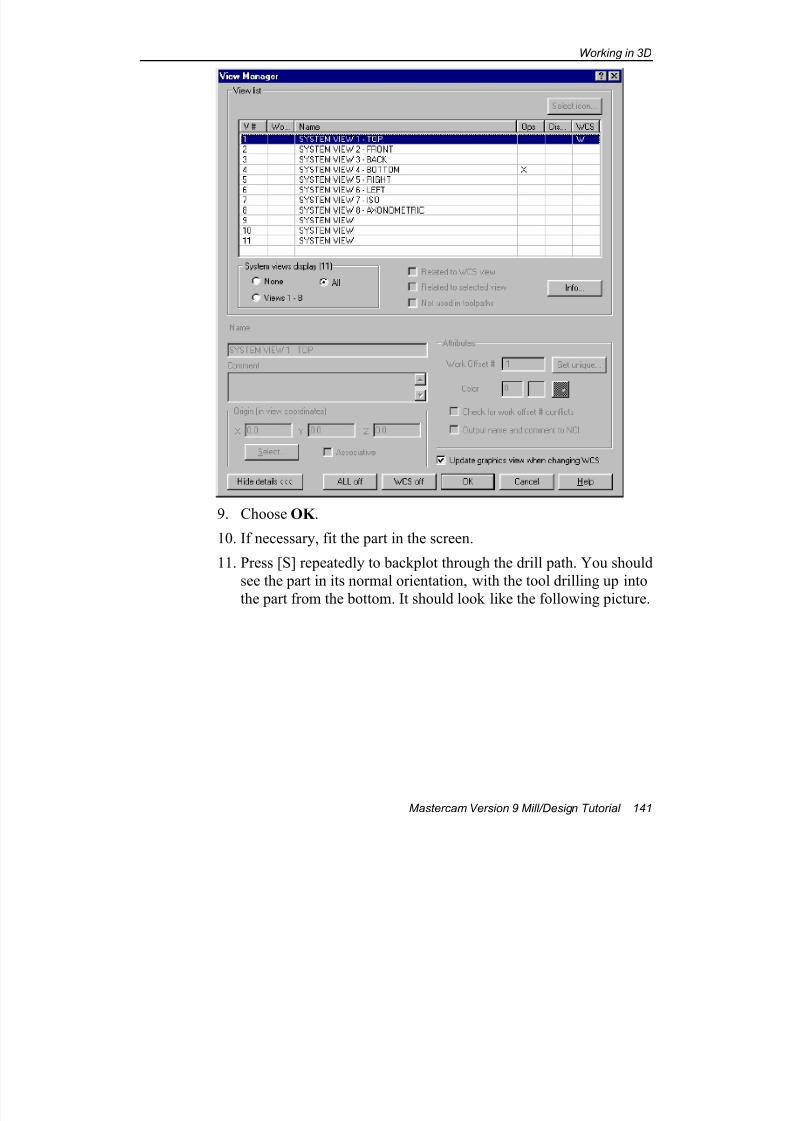
7/18/2019 V9 Mill-Design Tutorial (metric).pdf
http://slidepdf.com/reader/full/v9-mill-design-tutorial-metricpdf 153/453
Working in 3D
Mastercam Version 9 Mill/Design Tutorial 141
9. Choose OK .
10. If necessary, fit the part in the screen.
11. Press [S] repeatedly to backplot through the drill path. You should
see the part in its normal orientation, with the tool drilling up into
the part from the bottom. It should look like the following picture.
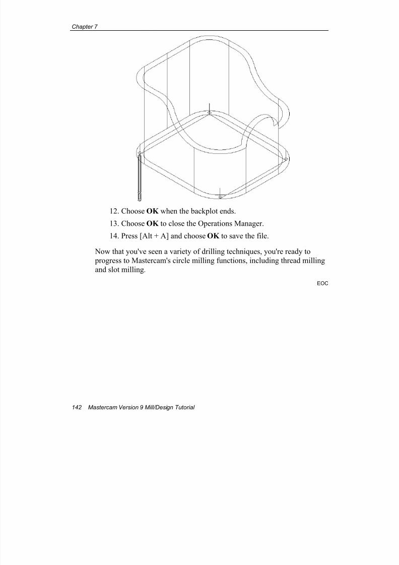
7/18/2019 V9 Mill-Design Tutorial (metric).pdf
http://slidepdf.com/reader/full/v9-mill-design-tutorial-metricpdf 154/453
Chapter 7
142 Mastercam Version 9 Mill/Design Tutorial
12. Choose OK when the backplot ends.
13. Choose OK to close the Operations Manager.
14. Press [Alt + A] and choose OK to save the file.
Now that you've seen a variety of drilling techniques, you're ready to
progress to Mastercam's circle milling functions, including thread milling
and slot milling.
EOC
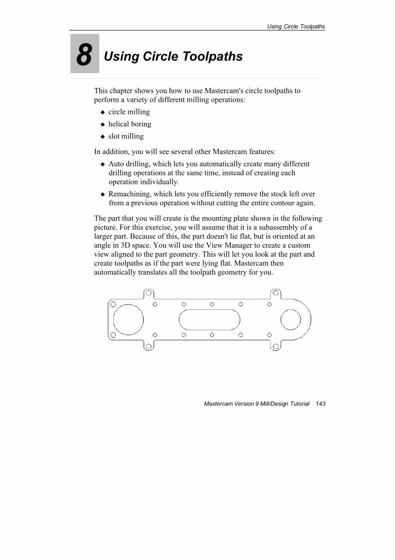
7/18/2019 V9 Mill-Design Tutorial (metric).pdf
http://slidepdf.com/reader/full/v9-mill-design-tutorial-metricpdf 155/453
Using Circle Toolpaths
Mastercam Version 9 Mill/Design Tutorial 143
8 Using Circle Toolpaths
This chapter shows you how to use Mastercam's circle toolpaths to
perform a variety of different milling operations:
circle milling
helical boring
slot milling
In addition, you will see several other Mastercam features:
Auto drilling, which lets you automatically create many different
drilling operations at the same time, instead of creating each
operation individually.
Remachining, which lets you efficiently remove the stock left overfrom a previous operation without cutting the entire contour again.
The part that you will create is the mounting plate shown in the following
picture. For this exercise, you will assume that it is a subassembly of a
larger part. Because of this, the part doesn't lie flat, but is oriented at an
angle in 3D space. You will use the View Manager to create a custom
view aligned to the part geometry. This will let you look at the part and
create toolpaths as if the part were lying flat. Mastercam then
automatically translates all the toolpath geometry for you.
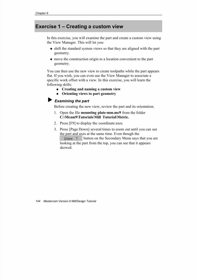
7/18/2019 V9 Mill-Design Tutorial (metric).pdf
http://slidepdf.com/reader/full/v9-mill-design-tutorial-metricpdf 156/453
Chapter 8
144 Mastercam Version 9 Mill/Design Tutorial
Exercise 1 – Creating a custom view
In this exercise, you will examine the part and create a custom view using
the View Manager. This will let you:
shift the standard system views so that they are aligned with the partgeometry.
move the construction origin to a location convenient to the part
geometry.
You can then use the new view to create toolpaths while the part appears
flat. If you wish, you can even use the View Manager to associate a
specific work offset with a view. In this exercise, you will learn the
following skills:
Creating and naming a custom view
Orienting views to part geometry
Examining the part
Before creating the new view, review the part and its orientation.
1. Open the file mounting plate-mm.mc9 from the folder
C:\Mcam9\Tutorials\Mill Tutorial\Metric.
2. Press [F9] to display the coordinate axes.
3. Press [Page Down] several times to zoom out until you can see
the part and axes at the same time. Even though the
button on the Secondary Menu says that you are
looking at the part from the top, you can see that it appears
skewed.
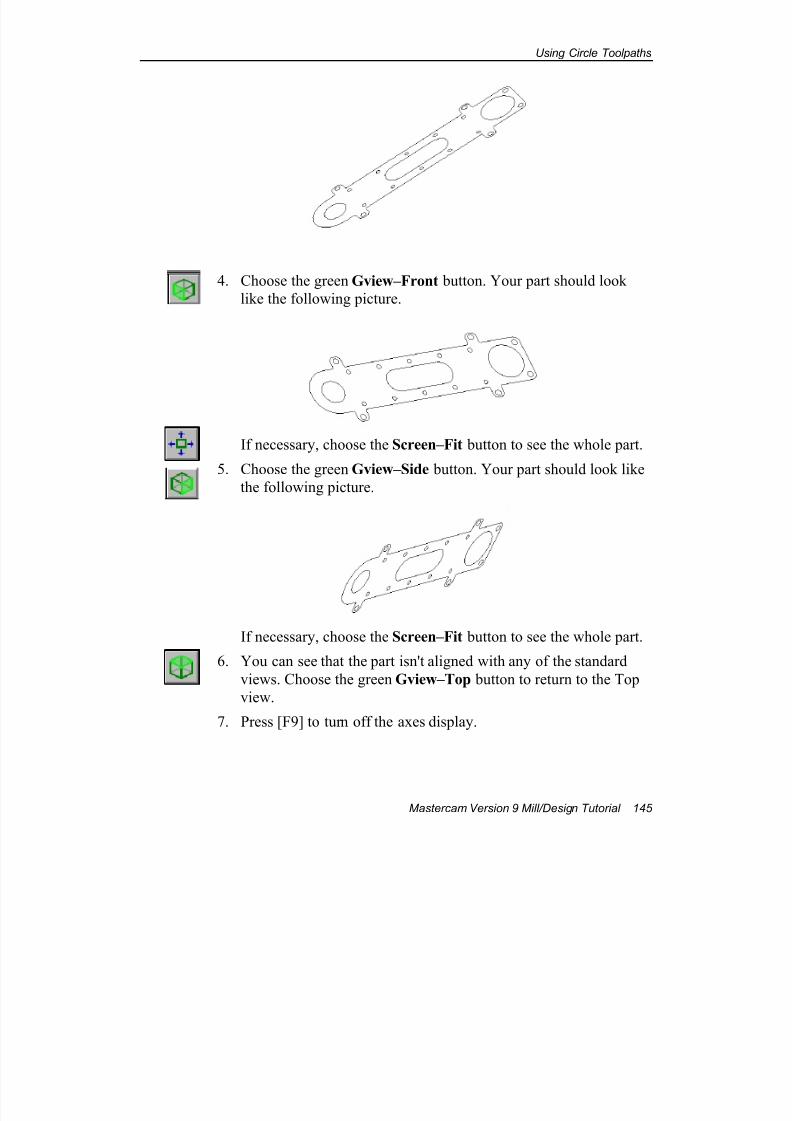
7/18/2019 V9 Mill-Design Tutorial (metric).pdf
http://slidepdf.com/reader/full/v9-mill-design-tutorial-metricpdf 157/453
Using Circle Toolpaths
Mastercam Version 9 Mill/Design Tutorial 145
4. Choose the green Gview–Front button. Your part should look
like the following picture.
If necessary, choose the Screen–Fit button to see the whole part.
5. Choose the green Gview–Side button. Your part should look like
the following picture.
If necessary, choose the Screen–Fit button to see the whole part.
6. You can see that the part isn't aligned with any of the standard
views. Choose the green Gview–Top button to return to the Top
view.
7. Press [F9] to turn off the axes display.
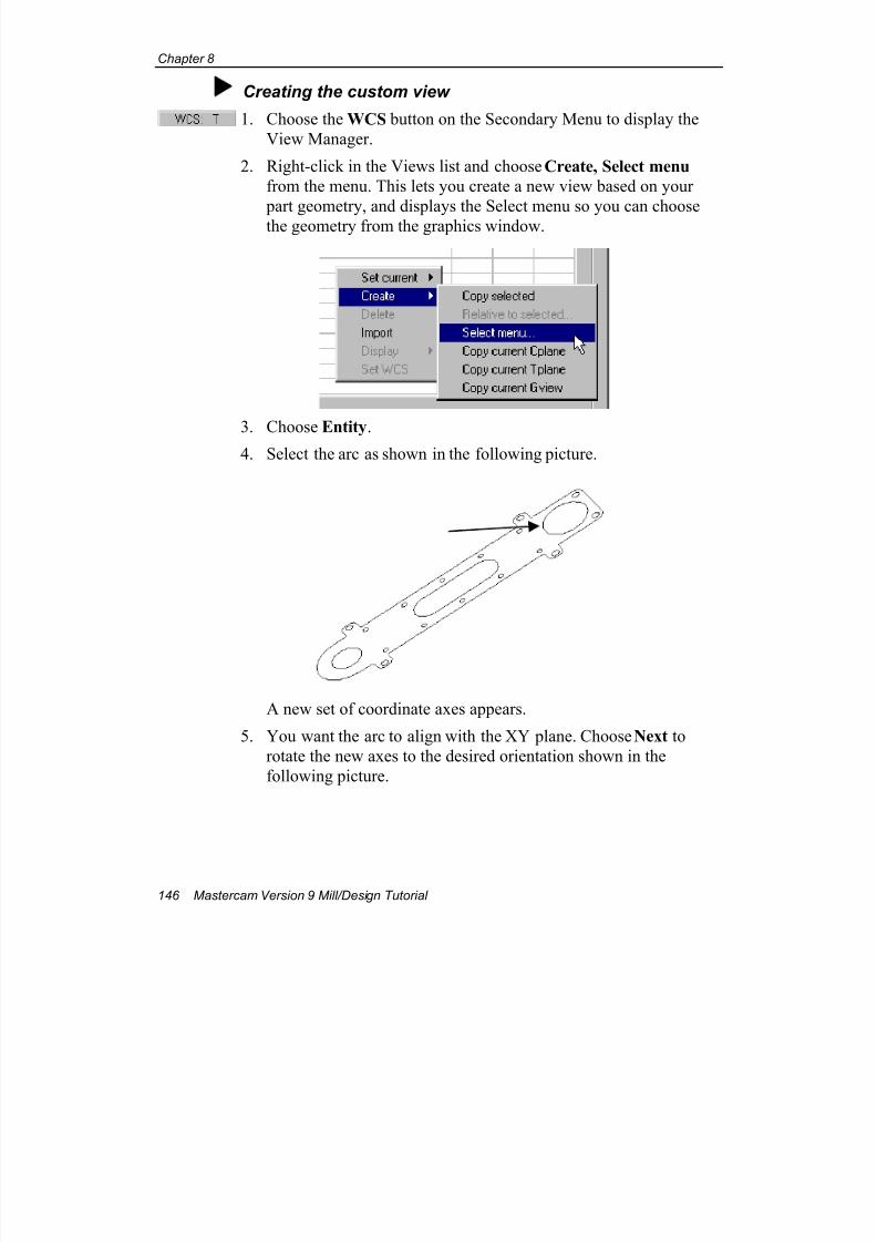
7/18/2019 V9 Mill-Design Tutorial (metric).pdf
http://slidepdf.com/reader/full/v9-mill-design-tutorial-metricpdf 158/453
Chapter 8
146 Mastercam Version 9 Mill/Design Tutorial
Creating the custom view
1. Choose the WCS button on the Secondary Menu to display the
View Manager.
2. Right-click in the Views list and choose Create, Select menu
from the menu. This lets you create a new view based on your
part geometry, and displays the Select menu so you can choose
the geometry from the graphics window.
3. Choose Entity.4. Select the arc as shown in the following picture.
A new set of coordinate axes appears.
5. You want the arc to align with the XY plane. Choose Next to
rotate the new axes to the desired orientation shown in the
following picture.
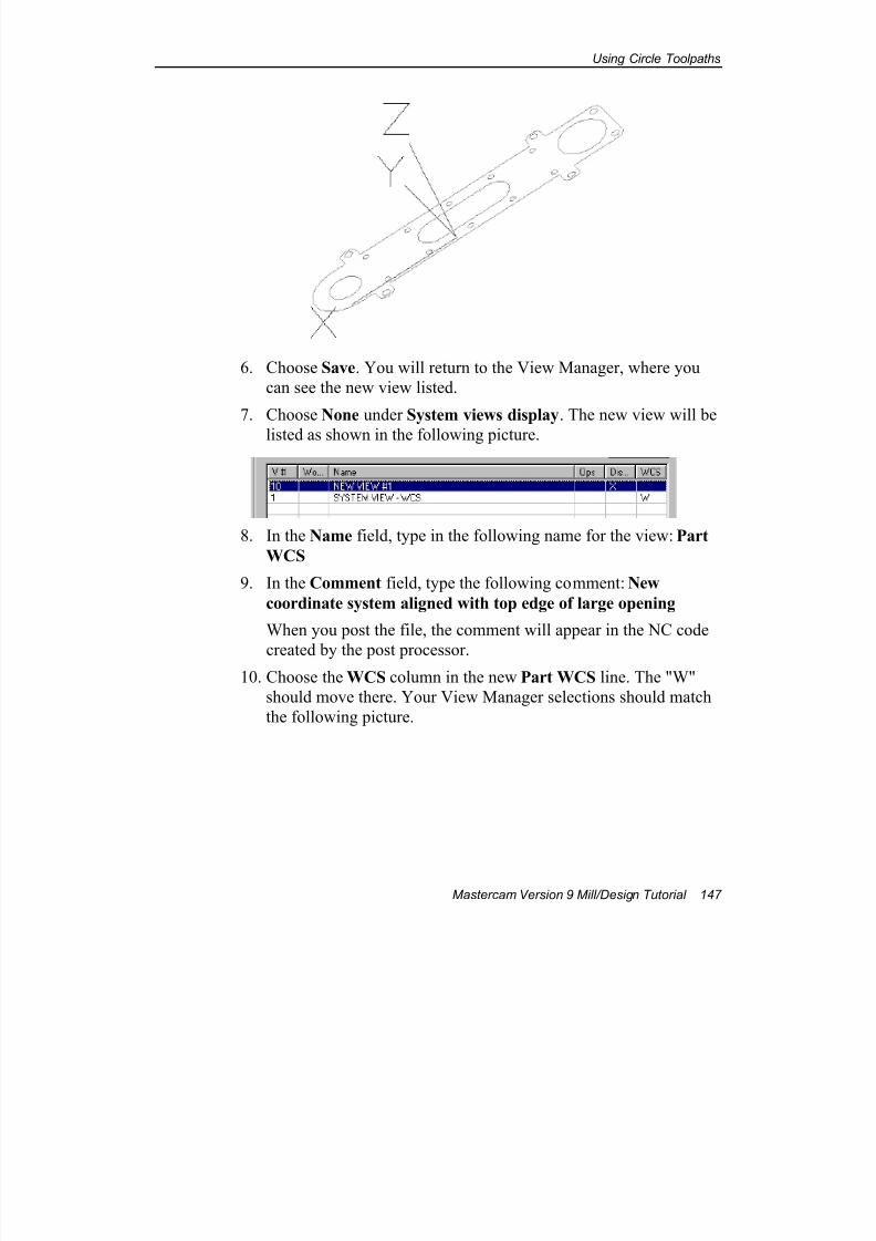
7/18/2019 V9 Mill-Design Tutorial (metric).pdf
http://slidepdf.com/reader/full/v9-mill-design-tutorial-metricpdf 159/453
Using Circle Toolpaths
Mastercam Version 9 Mill/Design Tutorial 147
6. Choose Save. You will return to the View Manager, where you
can see the new view listed.
7. Choose None under System views display. The new view will be
listed as shown in the following picture.
8. In the Name field, type in the following name for the view: Part
WCS
9. In the Comment field, type the following comment: New
coordinate system aligned with top edge of large opening
When you post the file, the comment will appear in the NC code
created by the post processor.10. Choose the WCS column in the new Part WCS line. The "W"
should move there. Your View Manager selections should match
the following picture.
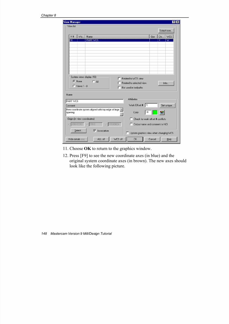
7/18/2019 V9 Mill-Design Tutorial (metric).pdf
http://slidepdf.com/reader/full/v9-mill-design-tutorial-metricpdf 160/453
Chapter 8
148 Mastercam Version 9 Mill/Design Tutorial
11. Choose OK to return to the graphics window.
12. Press [F9] to see the new coordinate axes (in blue) and the
original system coordinate axes (in brown). The new axes should
look like the following picture.
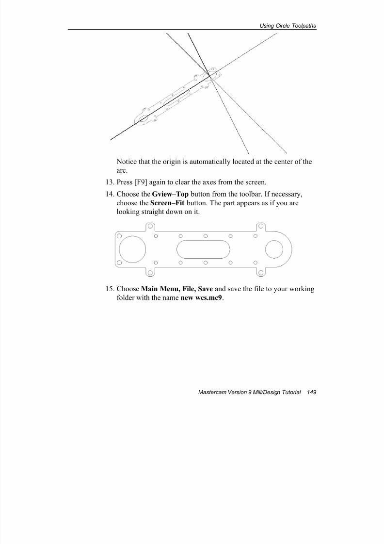
7/18/2019 V9 Mill-Design Tutorial (metric).pdf
http://slidepdf.com/reader/full/v9-mill-design-tutorial-metricpdf 161/453
Using Circle Toolpaths
Mastercam Version 9 Mill/Design Tutorial 149
Notice that the origin is automatically located at the center of the
arc.
13. Press [F9] again to clear the axes from the screen.
14. Choose the Gview–Top button from the toolbar. If necessary,
choose the Screen–Fit button. The part appears as if you are
looking straight down on it.
15. Choose Main Menu, File, Save and save the file to your working
folder with the name new wcs.mc9.
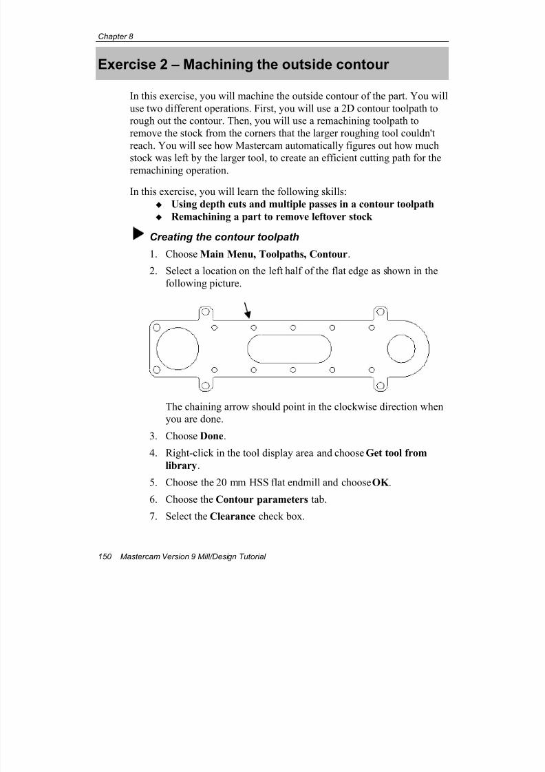
7/18/2019 V9 Mill-Design Tutorial (metric).pdf
http://slidepdf.com/reader/full/v9-mill-design-tutorial-metricpdf 162/453
Chapter 8
150 Mastercam Version 9 Mill/Design Tutorial
Exercise 2 – Machining the outside contour
In this exercise, you will machine the outside contour of the part. You will
use two different operations. First, you will use a 2D contour toolpath to
rough out the contour. Then, you will use a remachining toolpath to
remove the stock from the corners that the larger roughing tool couldn'treach. You will see how Mastercam automatically figures out how much
stock was left by the larger tool, to create an efficient cutting path for the
remachining operation.
In this exercise, you will learn the following skills:
Using depth cuts and multiple passes in a contour toolpath
Remachining a part to remove leftover stock
Creating the contour toolpath
1. Choose Main Menu, Toolpaths, Contour.
2. Select a location on the left half of the flat edge as shown in thefollowing picture.
The chaining arrow should point in the clockwise direction whenyou are done.
3. Choose Done.
4. Right-click in the tool display area and choose Get tool from
library.
5. Choose the 20 mm HSS flat endmill and choose OK .
6. Choose the Contour parameters tab.
7. Select the Clearance check box.
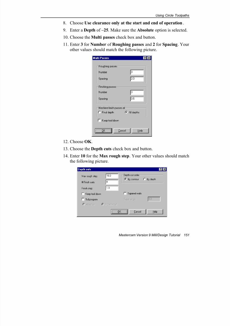
7/18/2019 V9 Mill-Design Tutorial (metric).pdf
http://slidepdf.com/reader/full/v9-mill-design-tutorial-metricpdf 163/453
Using Circle Toolpaths
Mastercam Version 9 Mill/Design Tutorial 151
8. Choose Use clearance only at the start and end of operation.
9. Enter a Depth of –25. Make sure the Absolute option is selected.
10. Choose the Multi passes check box and button.
11. Enter 3 for Number of Roughing passes and 2 for Spacing. Your
other values should match the following picture.
12. Choose OK .
13. Choose the Depth cuts check box and button.
14. Enter 10 for the Max rough step. Your other values should match
the following picture.
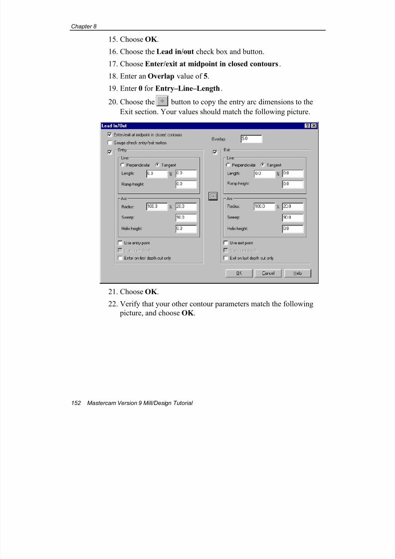
7/18/2019 V9 Mill-Design Tutorial (metric).pdf
http://slidepdf.com/reader/full/v9-mill-design-tutorial-metricpdf 164/453
Chapter 8
152 Mastercam Version 9 Mill/Design Tutorial
15. Choose OK .
16. Choose the Lead in/out check box and button.
17. Choose Enter/exit at midpoint in closed contours.
18. Enter an Overlap value of 5.
19. Enter 0 for Entry–Line–Length.
20. Choose the button to copy the entry arc dimensions to the
Exit section. Your values should match the following picture.
21. Choose OK .22. Verify that your other contour parameters match the following
picture, and choose OK .
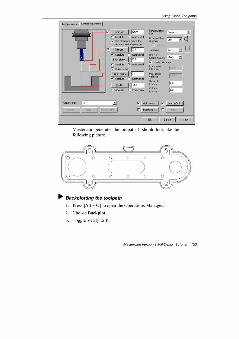
7/18/2019 V9 Mill-Design Tutorial (metric).pdf
http://slidepdf.com/reader/full/v9-mill-design-tutorial-metricpdf 165/453
Using Circle Toolpaths
Mastercam Version 9 Mill/Design Tutorial 153
Mastercam generates the toolpath. It should look like the
following picture.
Backplotting the toolpath
1. Press [Alt + O] to open the Operations Manager.
2. Choose Backplot.
3. Toggle Verify to Y.
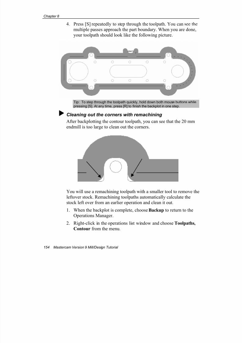
7/18/2019 V9 Mill-Design Tutorial (metric).pdf
http://slidepdf.com/reader/full/v9-mill-design-tutorial-metricpdf 166/453
Chapter 8
154 Mastercam Version 9 Mill/Design Tutorial
4. Press [S] repeatedly to step through the toolpath. You can see the
multiple passes approach the part boundary. When you are done,
your toolpath should look like the following picture.
Tip: To step through the toolpath quickly, hold down both mouse buttons whilepressing [S]. At any time, press [R] to finish the backplot in one step.
Cleaning out the corners with remachining
After backplotting the contour toolpath, you can see that the 20 mmendmill is too large to clean out the corners.
You will use a remachining toolpath with a smaller tool to remove the
leftover stock. Remachining toolpaths automatically calculate the
stock left over from an earlier operation and clean it out.
1. When the backplot is complete, choose Backup to return to the
Operations Manager.
2. Right-click in the operations list window and choose Toolpaths,
Contour from the menu.
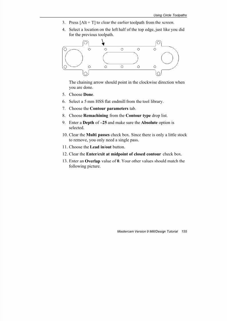
7/18/2019 V9 Mill-Design Tutorial (metric).pdf
http://slidepdf.com/reader/full/v9-mill-design-tutorial-metricpdf 167/453
Using Circle Toolpaths
Mastercam Version 9 Mill/Design Tutorial 155
3. Press [Alt + T] to clear the earlier toolpath from the screen.
4. Select a location on the left half of the top edge, just like you did
for the previous toolpath.
The chaining arrow should point in the clockwise direction when
you are done.
5. Choose Done.
6. Select a 5 mm HSS flat endmill from the tool library.
7. Choose the Contour parameters tab.
8. Choose Remachining from the Contour type drop list.
9. Enter a Depth of –25 and make sure the Absolute option is
selected.
10. Clear the Multi passes check box. Since there is only a little stock
to remove, you only need a single pass.
11. Choose the Lead in/out button.
12. Clear the Enter/exit at midpoint of closed contour check box.
13. Enter an Overlap value of 0. Your other values should match the
following picture.
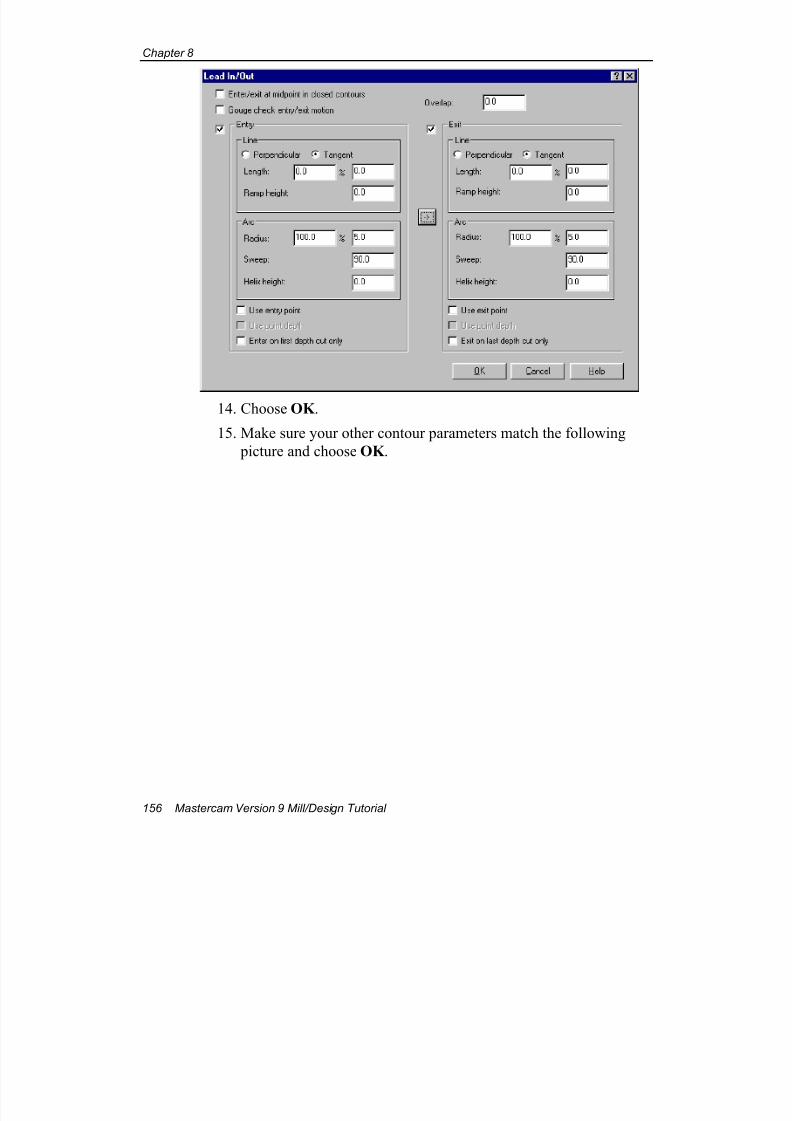
7/18/2019 V9 Mill-Design Tutorial (metric).pdf
http://slidepdf.com/reader/full/v9-mill-design-tutorial-metricpdf 168/453
Chapter 8
156 Mastercam Version 9 Mill/Design Tutorial
14. Choose OK .
15. Make sure your other contour parameters match the following
picture and choose OK .
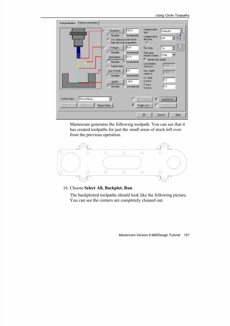
7/18/2019 V9 Mill-Design Tutorial (metric).pdf
http://slidepdf.com/reader/full/v9-mill-design-tutorial-metricpdf 169/453
Using Circle Toolpaths
Mastercam Version 9 Mill/Design Tutorial 157
Mastercam generates the following toolpath. You can see that it
has created toolpaths for just the small areas of stock left over
from the previous operation.
16. Choose Select All, Backplot, Run.
The backplotted toolpaths should look like the following picture.
You can see the corners are completely cleaned out.
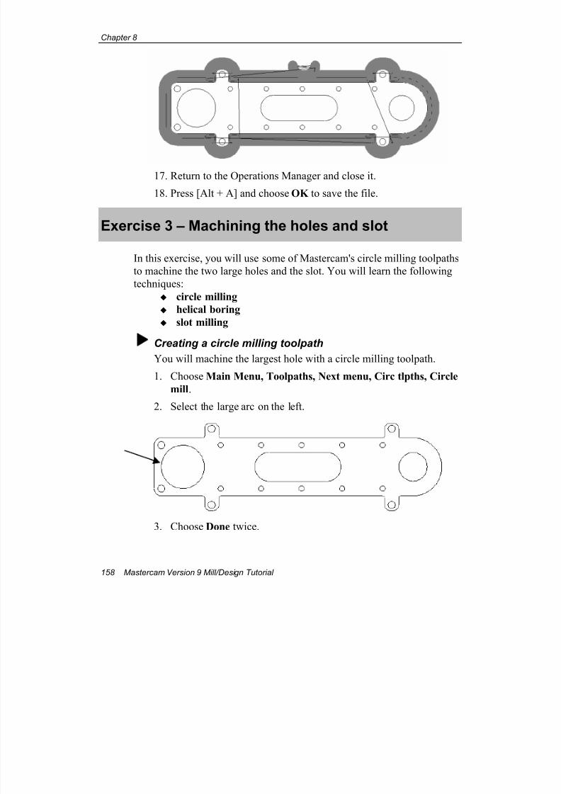
7/18/2019 V9 Mill-Design Tutorial (metric).pdf
http://slidepdf.com/reader/full/v9-mill-design-tutorial-metricpdf 170/453
Chapter 8
158 Mastercam Version 9 Mill/Design Tutorial
17. Return to the Operations Manager and close it.
18. Press [Alt + A] and choose OK to save the file.
Exercise 3 – Machining the holes and slot
In this exercise, you will use some of Mastercam's circle milling toolpaths
to machine the two large holes and the slot. You will learn the following
techniques:
circle milling
helical boring
slot milling
Creating a circle milling toolpath
You will machine the largest hole with a circle milling toolpath.
1. Choose Main Menu, Toolpaths, Next menu, Circ tlpths, Circle
mill.
2. Select the large arc on the left.
3. Choose Done twice.
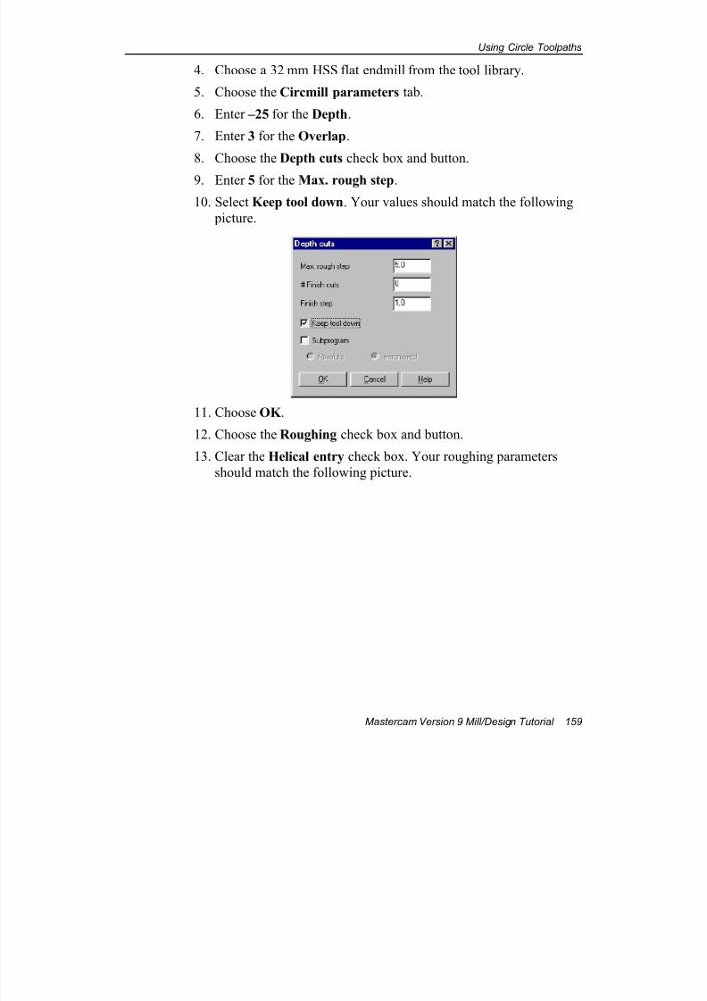
7/18/2019 V9 Mill-Design Tutorial (metric).pdf
http://slidepdf.com/reader/full/v9-mill-design-tutorial-metricpdf 171/453
Using Circle Toolpaths
Mastercam Version 9 Mill/Design Tutorial 159
4. Choose a 32 mm HSS flat endmill from the tool library.
5. Choose the Circmill parameters tab.
6. Enter –25 for the Depth.
7. Enter 3 for the Overlap.
8. Choose the Depth cuts check box and button.
9. Enter 5 for the Max. rough step.
10. Select Keep tool down. Your values should match the following
picture.
11. Choose OK .
12. Choose the Roughing check box and button.
13. Clear the Helical entry check box. Your roughing parameters
should match the following picture.
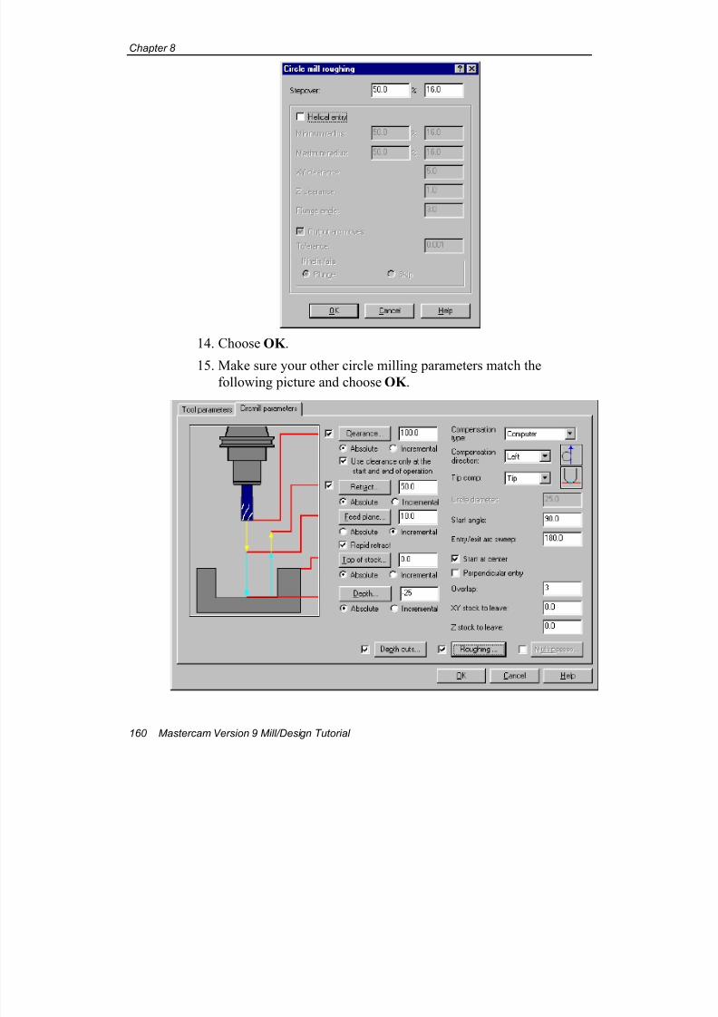
7/18/2019 V9 Mill-Design Tutorial (metric).pdf
http://slidepdf.com/reader/full/v9-mill-design-tutorial-metricpdf 172/453
Chapter 8
160 Mastercam Version 9 Mill/Design Tutorial
14. Choose OK .
15. Make sure your other circle milling parameters match the
following picture and choose OK .
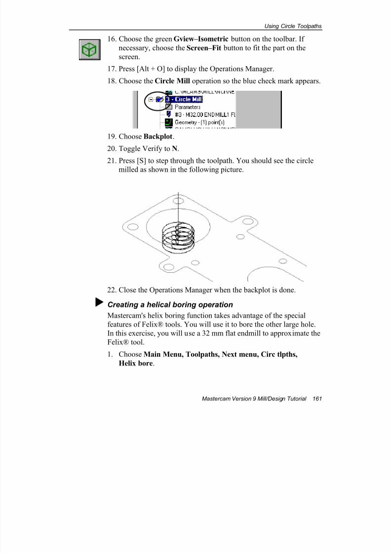
7/18/2019 V9 Mill-Design Tutorial (metric).pdf
http://slidepdf.com/reader/full/v9-mill-design-tutorial-metricpdf 173/453
Using Circle Toolpaths
Mastercam Version 9 Mill/Design Tutorial 161
16. Choose the green Gview–Isometric button on the toolbar. If
necessary, choose the Screen–Fit button to fit the part on the
screen.
17. Press [Alt + O] to display the Operations Manager.
18. Choose the Circle Mill operation so the blue check mark appears.
19. Choose Backplot.
20. Toggle Verify to N.
21. Press [S] to step through the toolpath. You should see the circle
milled as shown in the following picture.
22. Close the Operations Manager when the backplot is done.
Creating a helical boring operation
Mastercam's helix boring function takes advantage of the special
features of Felix® tools. You will use it to bore the other large hole.
In this exercise, you will use a 32 mm flat endmill to approximate the
Felix® tool.
1. Choose Main Menu, Toolpaths, Next menu, Circ tlpths,
Helix bore.

7/18/2019 V9 Mill-Design Tutorial (metric).pdf
http://slidepdf.com/reader/full/v9-mill-design-tutorial-metricpdf 174/453
Chapter 8
162 Mastercam Version 9 Mill/Design Tutorial
2. Select the large arc on the right.
3. Choose Done twice.
4. Choose the 32 mm flat endmill.
5. Choose the Helix bore parameters tab.
6. Enter –25 for the Depth.
7. Choose Start at center.
8. Enter 3 for the Overlap. Your values should match the following
picture.
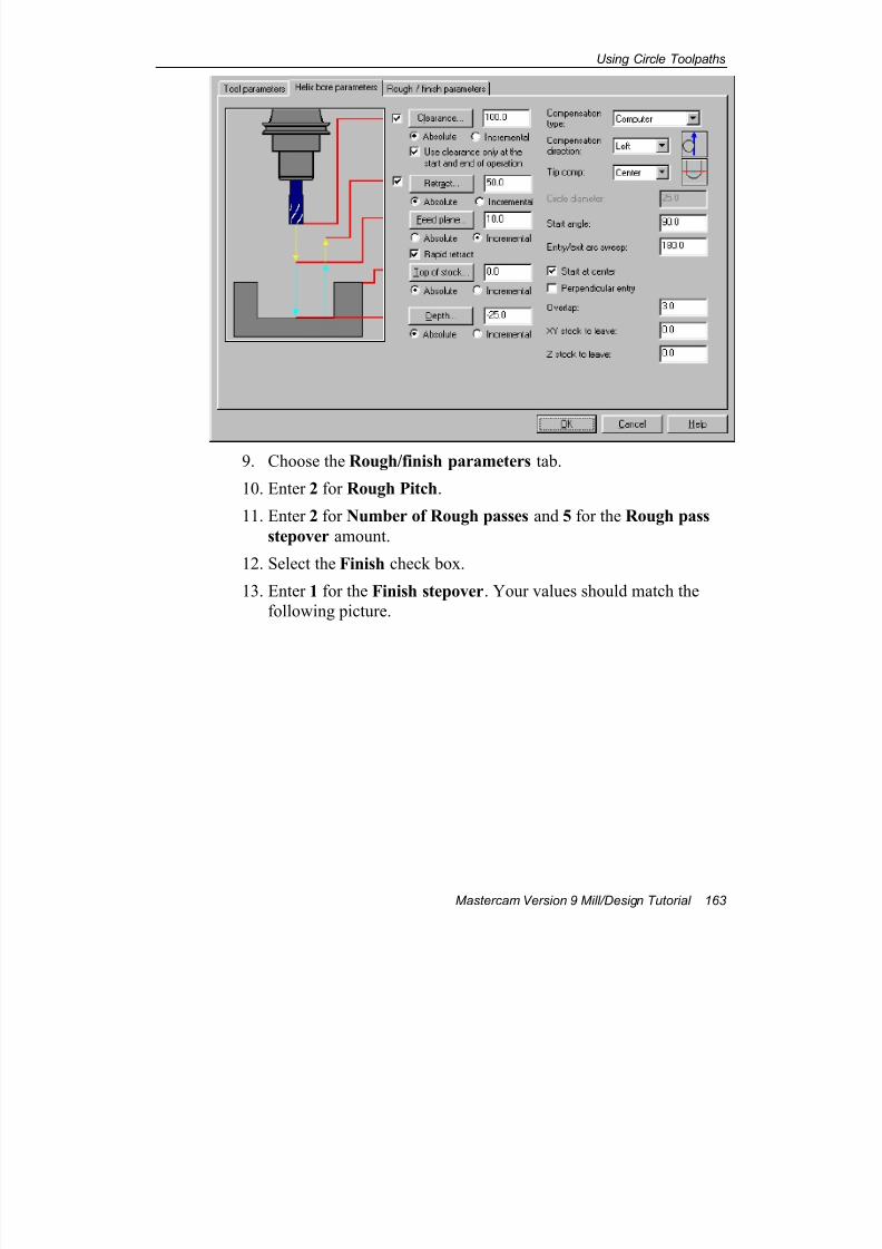
7/18/2019 V9 Mill-Design Tutorial (metric).pdf
http://slidepdf.com/reader/full/v9-mill-design-tutorial-metricpdf 175/453
Using Circle Toolpaths
Mastercam Version 9 Mill/Design Tutorial 163
9. Choose the Rough/finish parameters tab.
10. Enter 2 for Rough Pitch.
11. Enter 2 for Number of Rough passes and 5 for the Rough pass
stepover amount.
12. Select the Finish check box.
13. Enter 1 for the Finish stepover. Your values should match the
following picture.
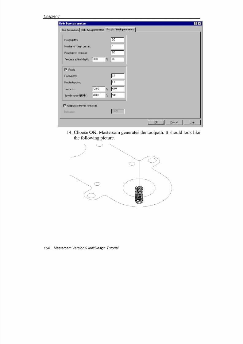
7/18/2019 V9 Mill-Design Tutorial (metric).pdf
http://slidepdf.com/reader/full/v9-mill-design-tutorial-metricpdf 176/453
Chapter 8
164 Mastercam Version 9 Mill/Design Tutorial
14. Choose OK . Mastercam generates the toolpath. It should look like
the following picture.
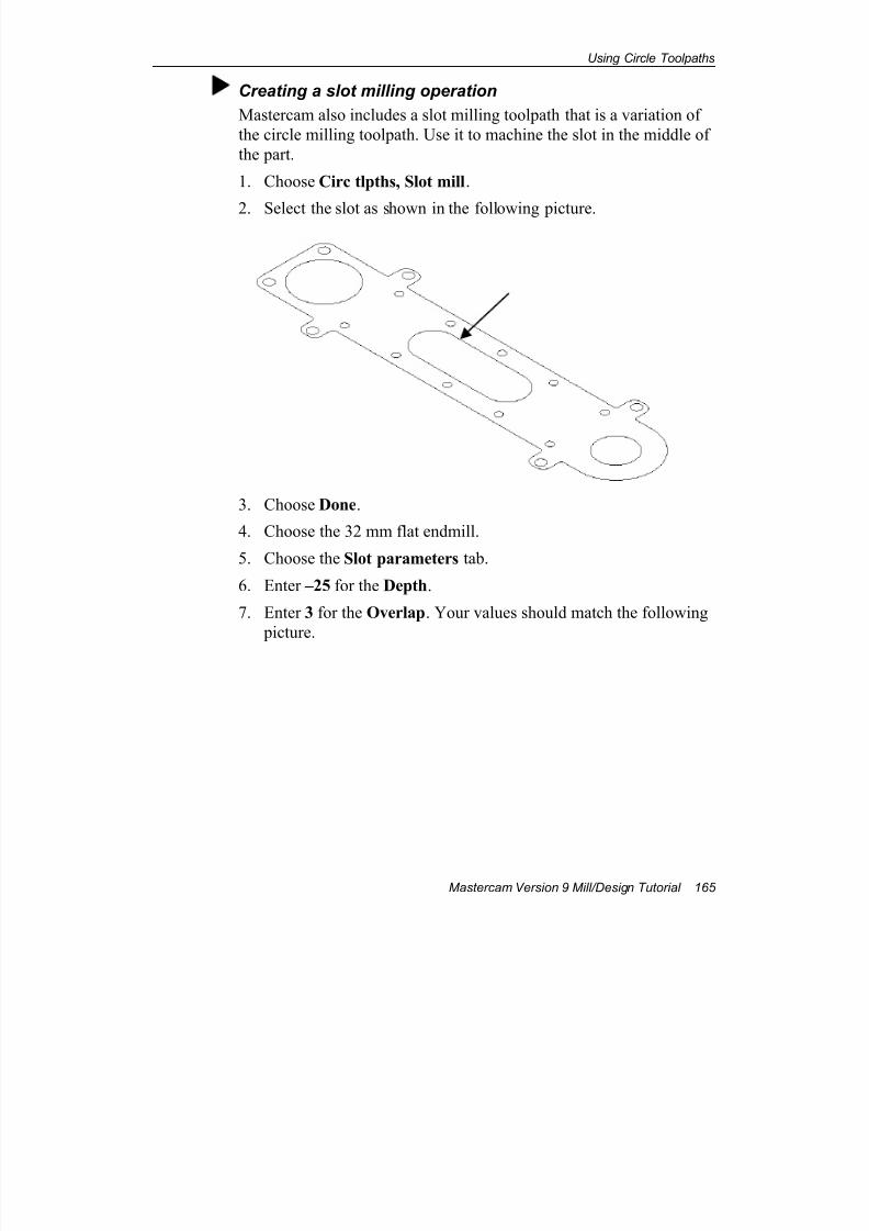
7/18/2019 V9 Mill-Design Tutorial (metric).pdf
http://slidepdf.com/reader/full/v9-mill-design-tutorial-metricpdf 177/453
Using Circle Toolpaths
Mastercam Version 9 Mill/Design Tutorial 165
Creating a slot milling operation
Mastercam also includes a slot milling toolpath that is a variation of
the circle milling toolpath. Use it to machine the slot in the middle of
the part.
1. Choose Circ tlpths, Slot mill.
2. Select the slot as shown in the following picture.
3. Choose Done.
4. Choose the 32 mm flat endmill.
5. Choose the Slot parameters tab.
6. Enter –25 for the Depth.
7. Enter 3 for the Overlap. Your values should match the following
picture.
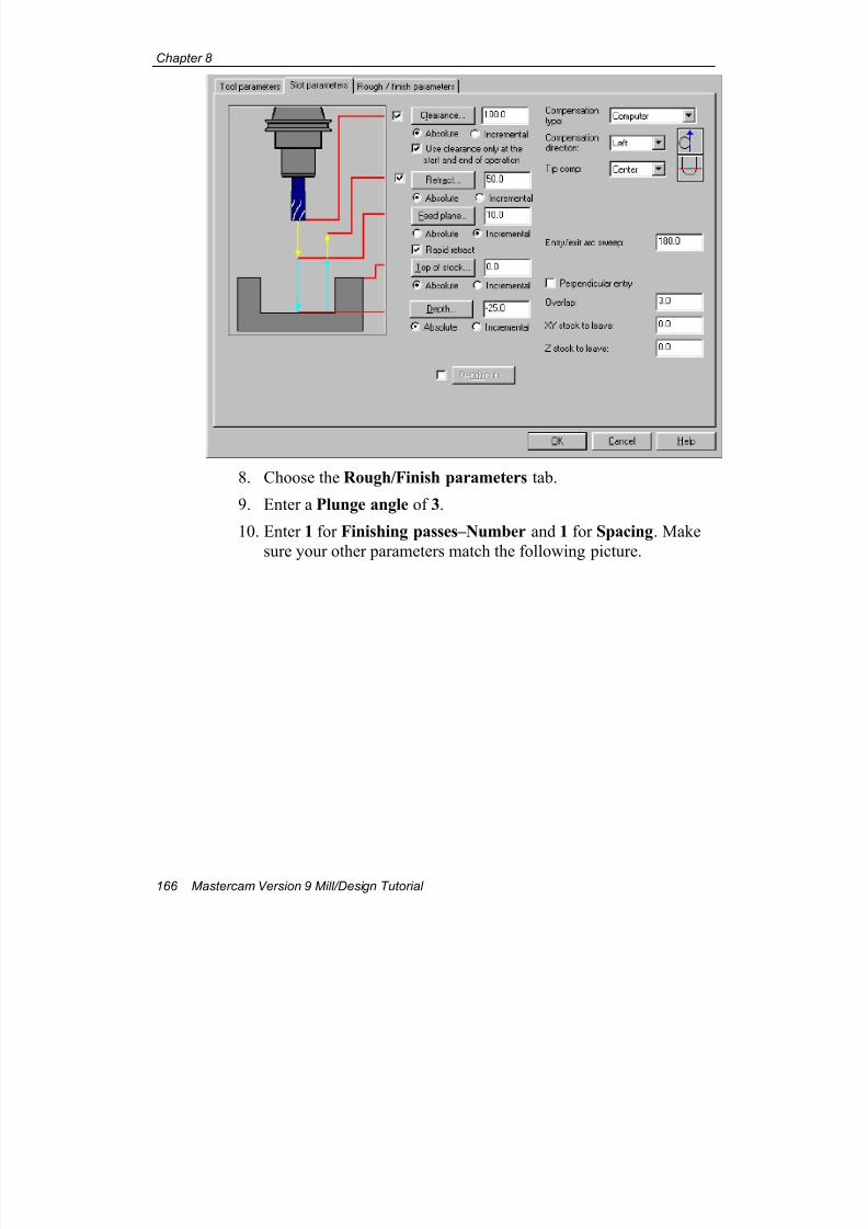
7/18/2019 V9 Mill-Design Tutorial (metric).pdf
http://slidepdf.com/reader/full/v9-mill-design-tutorial-metricpdf 178/453
Chapter 8
166 Mastercam Version 9 Mill/Design Tutorial
8. Choose the Rough/Finish parameters tab.
9. Enter a Plunge angle of 3.
10. Enter 1 for Finishing passes–Number and 1 for Spacing. Make
sure your other parameters match the following picture.
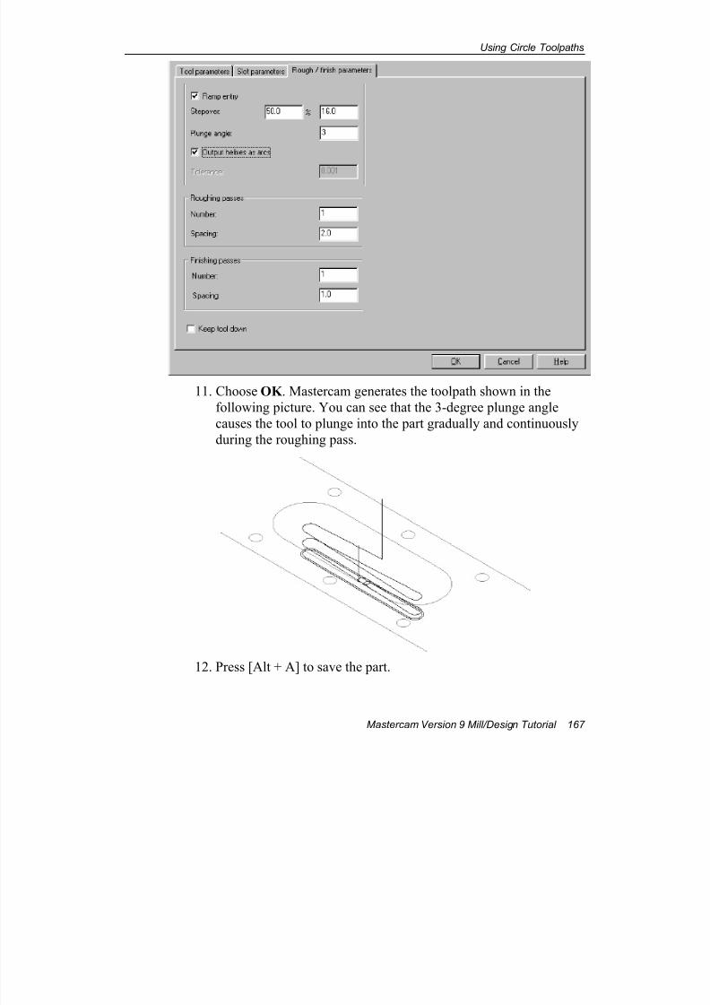
7/18/2019 V9 Mill-Design Tutorial (metric).pdf
http://slidepdf.com/reader/full/v9-mill-design-tutorial-metricpdf 179/453
Using Circle Toolpaths
Mastercam Version 9 Mill/Design Tutorial 167
11. Choose OK . Mastercam generates the toolpath shown in the
following picture. You can see that the 3-degree plunge angle
causes the tool to plunge into the part gradually and continuously
during the roughing pass.
12. Press [Alt + A] to save the part.
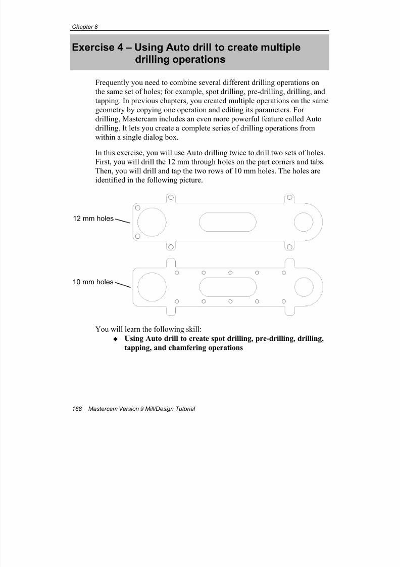
7/18/2019 V9 Mill-Design Tutorial (metric).pdf
http://slidepdf.com/reader/full/v9-mill-design-tutorial-metricpdf 180/453
Chapter 8
168 Mastercam Version 9 Mill/Design Tutorial
Exercise 4 – Using Auto drill to create multipledrilling operations
Frequently you need to combine several different drilling operations on
the same set of holes; for example, spot drilling, pre-drilling, drilling, and
tapping. In previous chapters, you created multiple operations on the samegeometry by copying one operation and editing its parameters. For
drilling, Mastercam includes an even more powerful feature called Auto
drilling. It lets you create a complete series of drilling operations from
within a single dialog box.
In this exercise, you will use Auto drilling twice to drill two sets of holes.
First, you will drill the 12 mm through holes on the part corners and tabs.
Then, you will drill and tap the two rows of 10 mm holes. The holes are
identified in the following picture.
You will learn the following skill:
Using Auto drill to create spot drilling, pre-drilling, drilling,
tapping, and chamfering operations
12 mm holes
10 mm holes
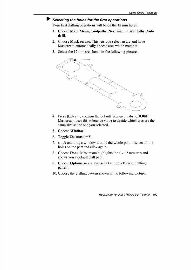
7/18/2019 V9 Mill-Design Tutorial (metric).pdf
http://slidepdf.com/reader/full/v9-mill-design-tutorial-metricpdf 181/453
Using Circle Toolpaths
Mastercam Version 9 Mill/Design Tutorial 169
Selecting the holes for the first operations
Your first drilling operations will be on the 12 mm holes.
1. Choose Main Menu, Toolpaths, Next menu, Circ tlpths, Auto
drill.
2. Choose Mask on arc. This lets you select an arc and have
Mastercam automatically choose arcs which match it.3. Select the 12 mm arc shown in the following picture.
4. Press [Enter] to confirm the default tolerance value of 0.001.
Mastercam uses this tolerance value to decide which arcs are the
same size as the one you selected.
5. Choose Window.
6. Toggle Use mask = Y.
7. Click and drag a window around the whole part to select all theholes on the part and click again.
8. Choose Done. Mastercam highlights the six 12 mm arcs and
shows you a default drill path.
9. Choose Options so you can select a more efficient drilling
pattern.
10. Choose the drilling pattern shown in the following picture.
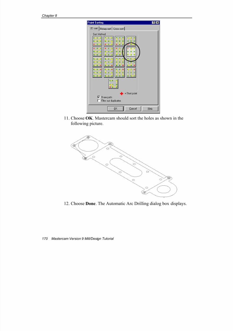
7/18/2019 V9 Mill-Design Tutorial (metric).pdf
http://slidepdf.com/reader/full/v9-mill-design-tutorial-metricpdf 182/453
Chapter 8
170 Mastercam Version 9 Mill/Design Tutorial
11. Choose OK . Mastercam should sort the holes as shown in the
following picture.
12. Choose Done. The Automatic Arc Drilling dialog box displays.
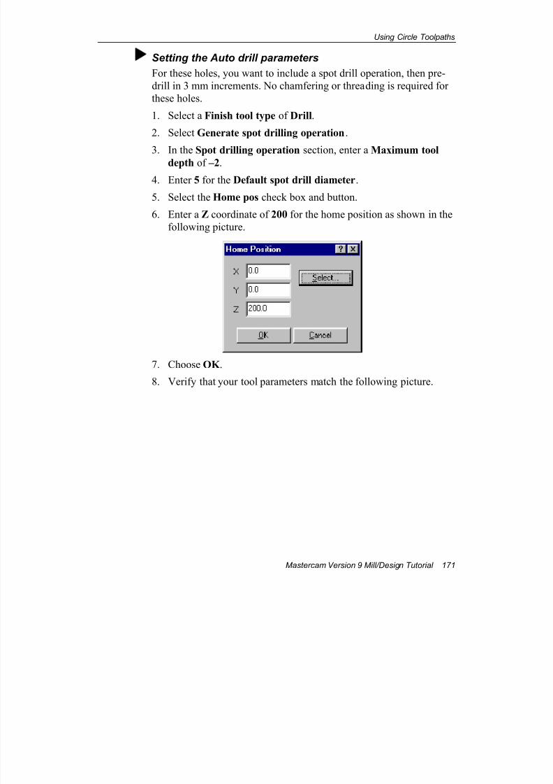
7/18/2019 V9 Mill-Design Tutorial (metric).pdf
http://slidepdf.com/reader/full/v9-mill-design-tutorial-metricpdf 183/453
Using Circle Toolpaths
Mastercam Version 9 Mill/Design Tutorial 171
Setting the Auto drill parameters
For these holes, you want to include a spot drill operation, then pre-
drill in 3 mm increments. No chamfering or threading is required for
these holes.
1. Select a Finish tool type of Drill.
2. Select Generate spot drilling operation.3. In the Spot drilling operation section, enter a Maximum tool
depth of –2.
4. Enter 5 for the Default spot drill diameter.
5. Select the Home pos check box and button.
6. Enter a Z coordinate of 200 for the home position as shown in the
following picture.
7. Choose OK .
8. Verify that your tool parameters match the following picture.
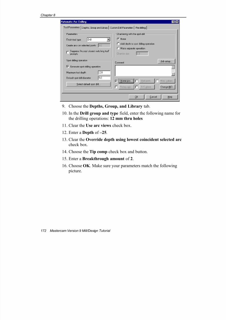
7/18/2019 V9 Mill-Design Tutorial (metric).pdf
http://slidepdf.com/reader/full/v9-mill-design-tutorial-metricpdf 184/453
Chapter 8
172 Mastercam Version 9 Mill/Design Tutorial
9. Choose the Depths, Group, and Library tab.
10. In the Drill group and type field, enter the following name forthe drilling operations: 12 mm thru holes
11. Clear the Use arc views check box.
12. Enter a Depth of –25.
13. Clear the Override depth using lowest coincident selected arc
check box.
14. Choose the Tip comp check box and button.
15. Enter a Breakthrough amount of 2.
16. Choose OK . Make sure your parameters match the following
picture.
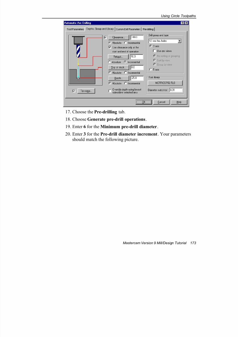
7/18/2019 V9 Mill-Design Tutorial (metric).pdf
http://slidepdf.com/reader/full/v9-mill-design-tutorial-metricpdf 185/453
Using Circle Toolpaths
Mastercam Version 9 Mill/Design Tutorial 173
17. Choose the Pre-drilling tab.
18. Choose Generate pre-drill operations.
19. Enter 6 for the Minimum pre-drill diameter.
20. Enter 3 for the Pre-drill diameter increment. Your parameters
should match the following picture.
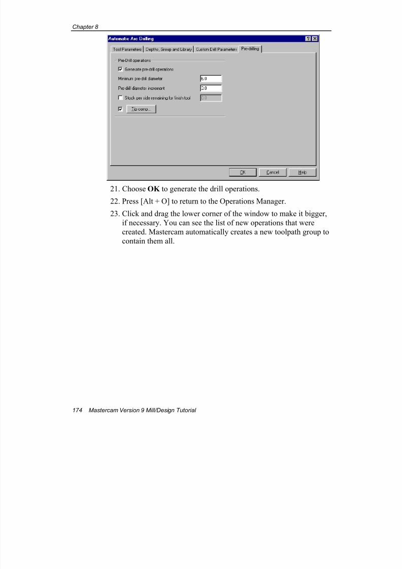
7/18/2019 V9 Mill-Design Tutorial (metric).pdf
http://slidepdf.com/reader/full/v9-mill-design-tutorial-metricpdf 186/453
Chapter 8
174 Mastercam Version 9 Mill/Design Tutorial
21. Choose OK to generate the drill operations.
22. Press [Alt + O] to return to the Operations Manager.
23. Click and drag the lower corner of the window to make it bigger,
if necessary. You can see the list of new operations that were
created. Mastercam automatically creates a new toolpath group to
contain them all.
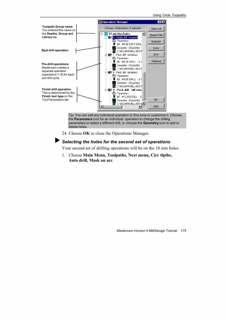
7/18/2019 V9 Mill-Design Tutorial (metric).pdf
http://slidepdf.com/reader/full/v9-mill-design-tutorial-metricpdf 187/453
Using Circle Toolpaths
Mastercam Version 9 Mill/Design Tutorial 175
Tip: You can edit any individual operation to fine-tune or customize it. Choosethe Parameters icon for an individual operation to change the drilling
parameters or select a different drill, or choose the Geometry icon to add ordelete holes.
24. Choose OK to close the Operations Manager.
Selecting the holes for the second set of operations
Your second set of drilling operations will be on the 10 mm holes.
1. Choose Main Menu, Toolpaths, Next menu, Circ tlpths,
Auto drill, Mask on arc.
Toolpath Group name
You entered this name on
the Depths, Group and
Library tab.
Spot drill operation
Pre-drill operations
Mastercam creates aseparate operation
(operations 7–8) for each
pre-drill cycle.
Finish drill operationThis is determined by the
Finish tool type on the
Tool Parameters tab.
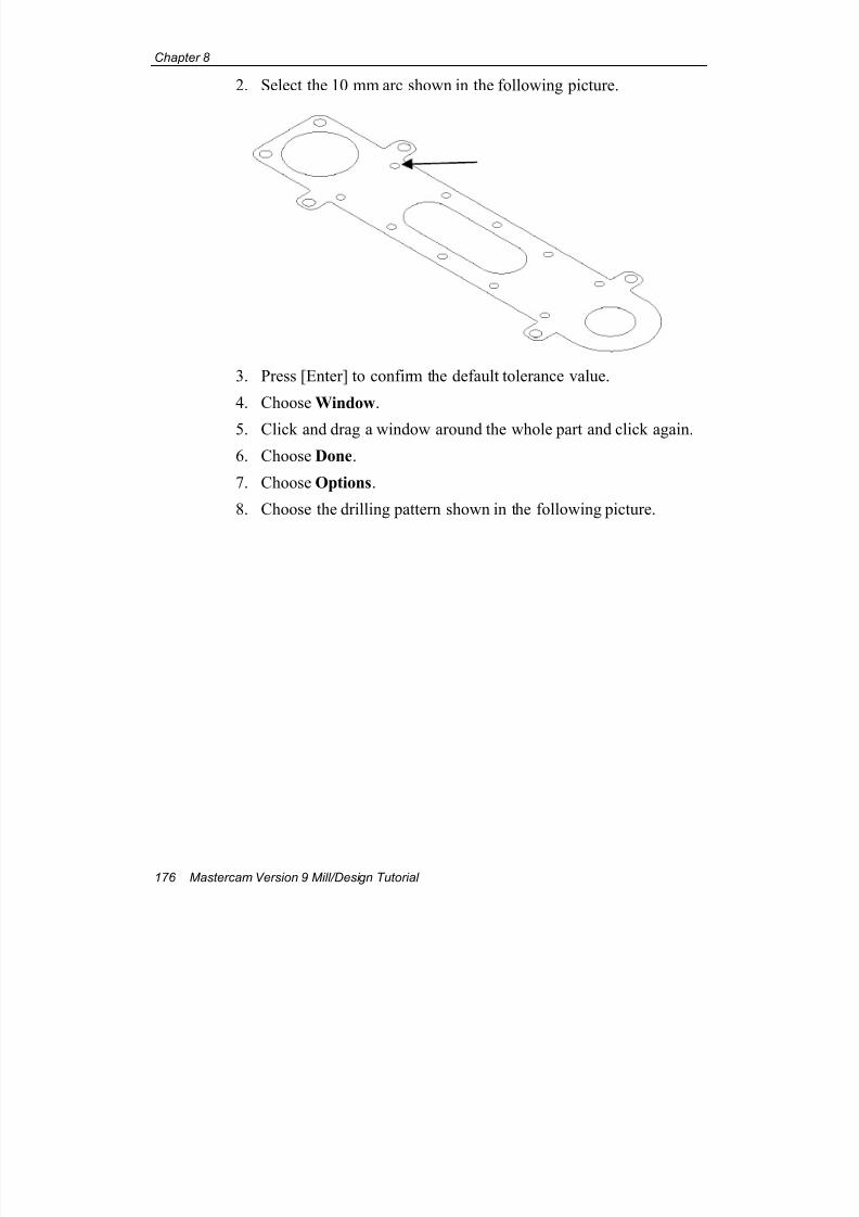
7/18/2019 V9 Mill-Design Tutorial (metric).pdf
http://slidepdf.com/reader/full/v9-mill-design-tutorial-metricpdf 188/453
Chapter 8
176 Mastercam Version 9 Mill/Design Tutorial
2. Select the 10 mm arc shown in the following picture.
3. Press [Enter] to confirm the default tolerance value.
4. Choose Window.
5. Click and drag a window around the whole part and click again.
6. Choose Done.
7. Choose Options.
8. Choose the drilling pattern shown in the following picture.
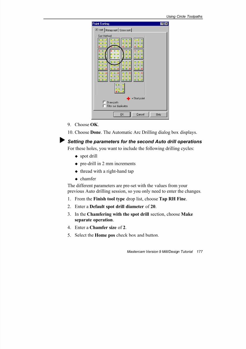
7/18/2019 V9 Mill-Design Tutorial (metric).pdf
http://slidepdf.com/reader/full/v9-mill-design-tutorial-metricpdf 189/453
Using Circle Toolpaths
Mastercam Version 9 Mill/Design Tutorial 177
9. Choose OK .
10. Choose Done. The Automatic Arc Drilling dialog box displays.
Setting the parameters for the second Auto drill operations
For these holes, you want to include the following drilling cycles:
spot drill
pre-drill in 2 mm increments
thread with a right-hand tap
chamfer
The different parameters are pre-set with the values from your
previous Auto drilling session, so you only need to enter the changes.
1. From the Finish tool type drop list, choose Tap RH Fine.
2. Enter a Default spot drill diameter of 20.
3. In the Chamfering with the spot drill section, choose Make
separate operation.
4. Enter a Chamfer size of 2.
5. Select the Home pos check box and button.
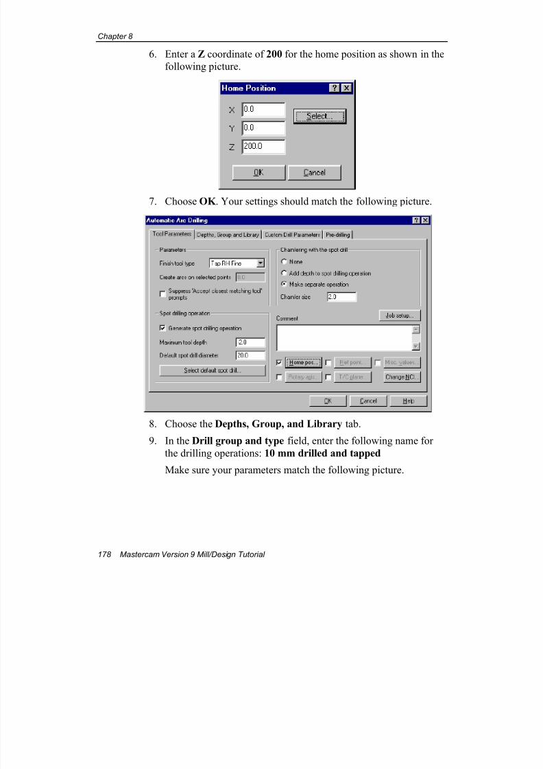
7/18/2019 V9 Mill-Design Tutorial (metric).pdf
http://slidepdf.com/reader/full/v9-mill-design-tutorial-metricpdf 190/453
Chapter 8
178 Mastercam Version 9 Mill/Design Tutorial
6. Enter a Z coordinate of 200 for the home position as shown in the
following picture.
7. Choose OK . Your settings should match the following picture.
8. Choose the Depths, Group, and Library tab.
9. In the Drill group and type field, enter the following name for
the drilling operations: 10 mm drilled and tapped
Make sure your parameters match the following picture.
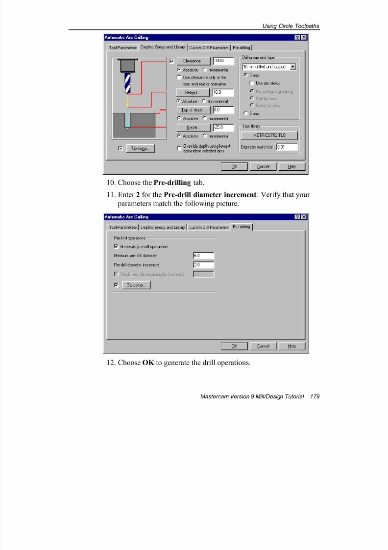
7/18/2019 V9 Mill-Design Tutorial (metric).pdf
http://slidepdf.com/reader/full/v9-mill-design-tutorial-metricpdf 191/453
Using Circle Toolpaths
Mastercam Version 9 Mill/Design Tutorial 179
10. Choose the Pre-drilling tab.
11. Enter 2 for the Pre-drill diameter increment. Verify that your parameters match the following picture.
12. Choose OK to generate the drill operations.

7/18/2019 V9 Mill-Design Tutorial (metric).pdf
http://slidepdf.com/reader/full/v9-mill-design-tutorial-metricpdf 192/453
Chapter 8
180 Mastercam Version 9 Mill/Design Tutorial
13. Press [Alt + O] to return to the Operations Manager.
14. Review the list of new operations that were created.
15. Choose OK to close the Operations Manager.
16. Press [Alt + A] to save the part.
You've now seen a variety of applications for Mastercam's circle
toolpaths. The next chapter will introduce you to more general purpose
pocketing toolpaths and related functions.
EOC
7/18/2019 V9 Mill-Design Tutorial (metric).pdf
http://slidepdf.com/reader/full/v9-mill-design-tutorial-metricpdf 193/453
Facing and Pocketing Toolpaths
Mastercam Version 9 Mill/Design Tutorial 181
9 Facing and Pocketing Toolpaths
This chapter shows you how to create a toolpath for facing your stock and
introduces some basic concepts for creating pocket toolpaths:
Comparing different pocket cutting methods
Using an entry point to start a pocket toolpath
Using a contour ramp toolpath
Exercise 1 – Facing the stock with high-speedloops
A facing toolpath quickly cleans the stock from the top of a part andcreates an even surface for future operations. When facing the stock, it is
important to have the tool overlap the edges of the part by at least 50% of
its diameter to prevent leaving little scallops of material at the edges of the
stock. In this exercise, you will learn the following skills:
Using Job Setup to define a stock boundary
Creating a facing toolpath
Entering stock boundaries
Assume that your stock is a 90 mm x 120 mm block. You want to
face it so that the final thickness will be 12 mm.
1. Open the file facing-mm.mc9 from the folderC:\Mcam9\Tutorials\Mill Tutorial\Metric. It should look like
the following picture.

7/18/2019 V9 Mill-Design Tutorial (metric).pdf
http://slidepdf.com/reader/full/v9-mill-design-tutorial-metricpdf 194/453
Chapter 9
182 Mastercam Version 9 Mill/Design Tutorial
2. Choose Main Menu, Toolpaths, Job Setup.
3. Enter 90 for the Y dimension of the stock model.
4. Enter 120 for the X dimension.
5. Enter 15 for the Z dimension. Since the goal is to finish with a 12mm block, you will use 15 mm as a starting dimension and face
off 3 mm of stock.
6. Enter 3 for Stock Origin–Z. By setting the top of the rough stock
at Z = 3, you ensure that when the facing toolpath is finished, the
top of the qualified stock will be Z = 0.
7. Select Display stock . Your other values should match the
following picture.
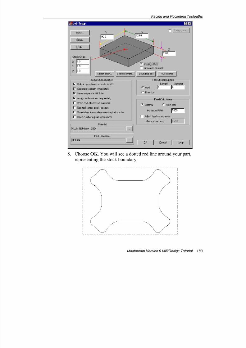
7/18/2019 V9 Mill-Design Tutorial (metric).pdf
http://slidepdf.com/reader/full/v9-mill-design-tutorial-metricpdf 195/453
Facing and Pocketing Toolpaths
Mastercam Version 9 Mill/Design Tutorial 183
8. Choose OK . You will see a dotted red line around your part,
representing the stock boundary.
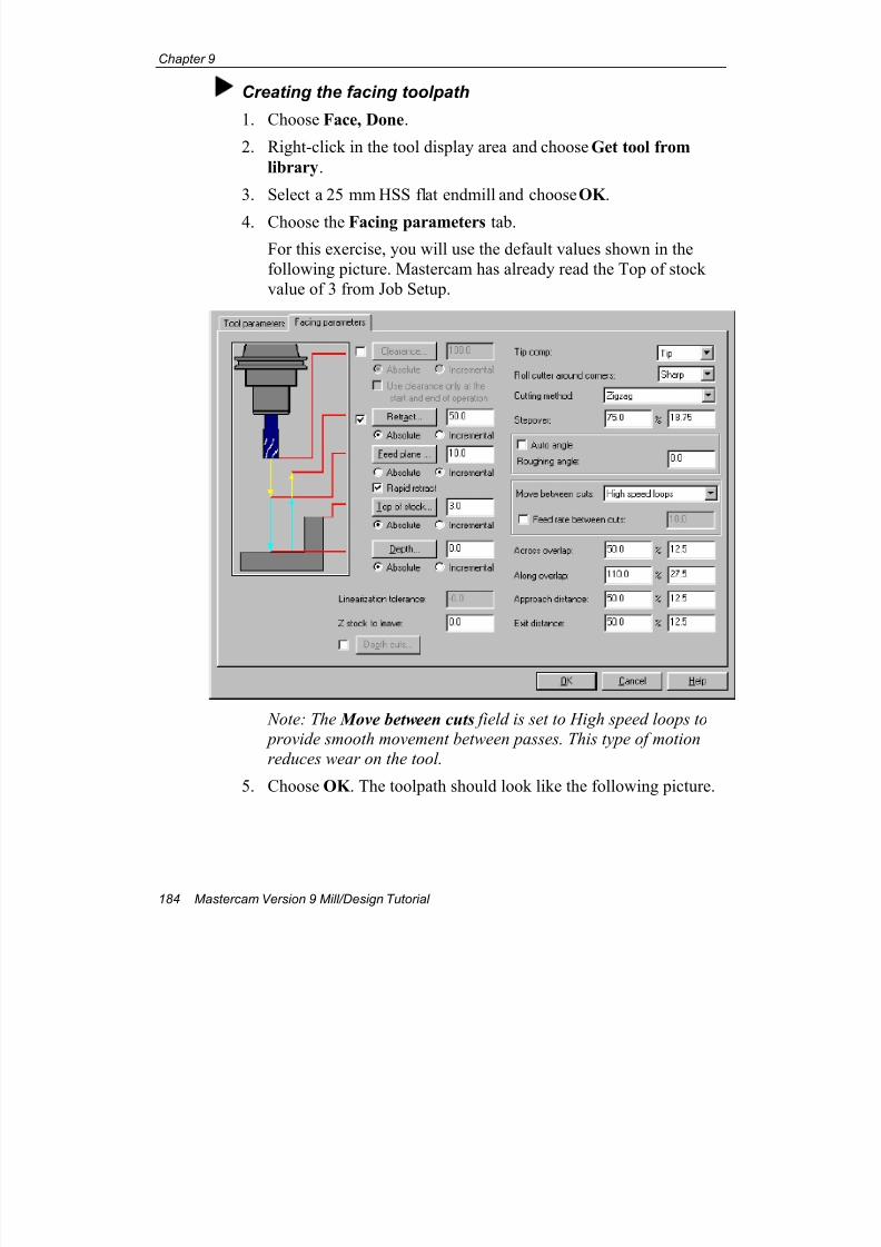
7/18/2019 V9 Mill-Design Tutorial (metric).pdf
http://slidepdf.com/reader/full/v9-mill-design-tutorial-metricpdf 196/453
Chapter 9
184 Mastercam Version 9 Mill/Design Tutorial
Creating the facing toolpath
1. Choose Face, Done.
2. Right-click in the tool display area and choose Get tool from
library.
3. Select a 25 mm HSS flat endmill and choose OK .
4. Choose the Facing parameters tab.
For this exercise, you will use the default values shown in the
following picture. Mastercam has already read the Top of stock
value of 3 from Job Setup.
Note: The Move between cuts field is set to High speed loops to
provide smooth movement between passes. This type of motion
reduces wear on the tool.
5. Choose OK . The toolpath should look like the following picture.
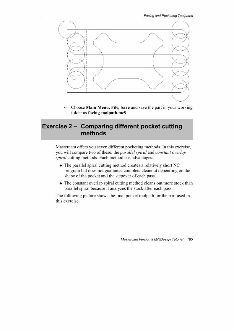
7/18/2019 V9 Mill-Design Tutorial (metric).pdf
http://slidepdf.com/reader/full/v9-mill-design-tutorial-metricpdf 197/453
Facing and Pocketing Toolpaths
Mastercam Version 9 Mill/Design Tutorial 185
6. Choose Main Menu, File, Save and save the part in your working
folder as facing toolpath.mc9.
Exercise 2 – Comparing different pocket cuttingmethods
Mastercam offers you seven different pocketing methods. In this exercise,
you will compare two of these: the parallel spiral and constant overlap
spiral cutting methods. Each method has advantages:
The parallel spiral cutting method creates a relatively short NC
program but does not guarantee complete cleanout depending on the
shape of the pocket and the stepover of each pass.
The constant overlap spiral cutting method cleans out more stock than
parallel spiral because it analyzes the stock after each pass.
The following picture shows the final pocket toolpath for the part used in
this exercise.
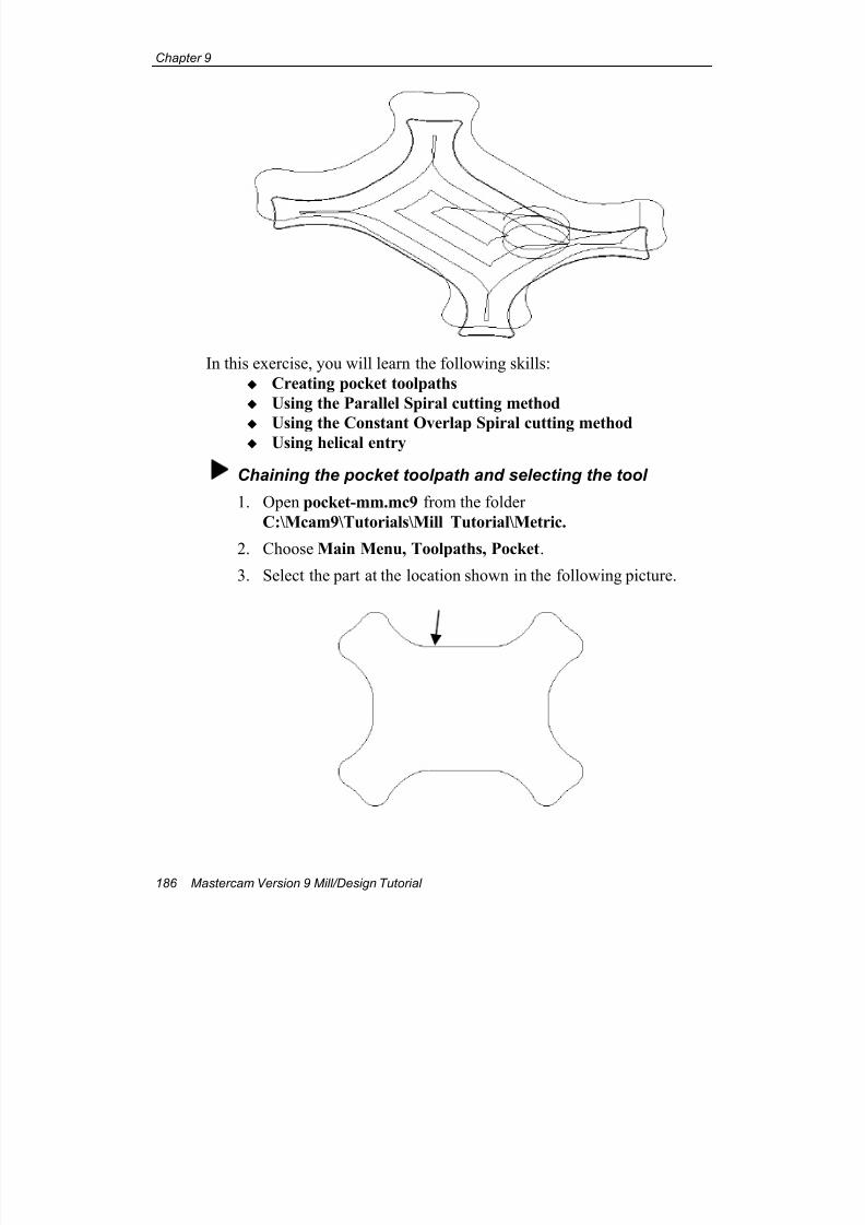
7/18/2019 V9 Mill-Design Tutorial (metric).pdf
http://slidepdf.com/reader/full/v9-mill-design-tutorial-metricpdf 198/453
Chapter 9
186 Mastercam Version 9 Mill/Design Tutorial
In this exercise, you will learn the following skills:
Creating pocket toolpaths
Using the Parallel Spiral cutting method
Using the Constant Overlap Spiral cutting method Using helical entry
Chaining the pocket toolpath and selecting the tool
1. Open pocket-mm.mc9 from the folder
C:\Mcam9\Tutorials\Mill Tutorial\Metric.
2. Choose Main Menu, Toolpaths, Pocket.
3. Select the part at the location shown in the following picture.
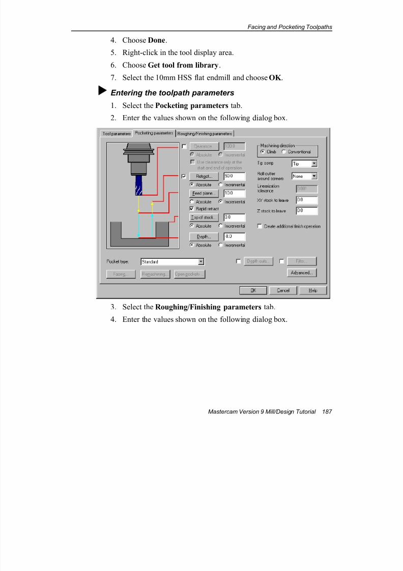
7/18/2019 V9 Mill-Design Tutorial (metric).pdf
http://slidepdf.com/reader/full/v9-mill-design-tutorial-metricpdf 199/453
Facing and Pocketing Toolpaths
Mastercam Version 9 Mill/Design Tutorial 187
4. Choose Done.
5. Right-click in the tool display area.
6. Choose Get tool from library.
7. Select the 10mm HSS flat endmill and choose OK .
Entering the toolpath parameters
1. Select the Pocketing parameters tab.
2. Enter the values shown on the following dialog box.
3. Select the Roughing/Finishing parameters tab.
4. Enter the values shown on the following dialog box.
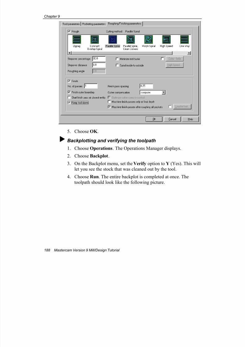
7/18/2019 V9 Mill-Design Tutorial (metric).pdf
http://slidepdf.com/reader/full/v9-mill-design-tutorial-metricpdf 200/453
Chapter 9
188 Mastercam Version 9 Mill/Design Tutorial
5. Choose OK .
Backplotting and verifying the toolpath
1. Choose Operations. The Operations Manager displays.
2. Choose Backplot.
3. On the Backplot menu, set the Verify option to Y (Yes). This will
let you see the stock that was cleaned out by the tool.
4. Choose Run. The entire backplot is completed at once. The
toolpath should look like the following picture.
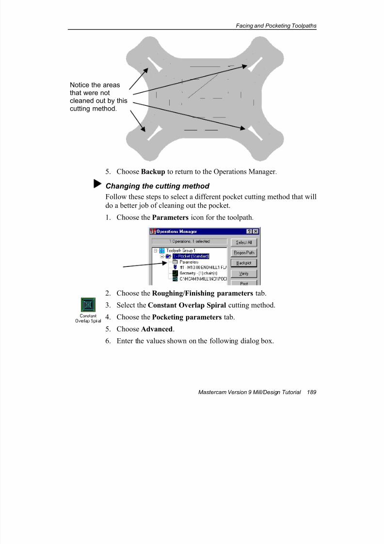
7/18/2019 V9 Mill-Design Tutorial (metric).pdf
http://slidepdf.com/reader/full/v9-mill-design-tutorial-metricpdf 201/453
Facing and Pocketing Toolpaths
Mastercam Version 9 Mill/Design Tutorial 189
5. Choose Backup to return to the Operations Manager.
Changing the cutting method
Follow these steps to select a different pocket cutting method that will
do a better job of cleaning out the pocket.
1. Choose the Parameters icon for the toolpath.
2. Choose the Roughing/Finishing parameters tab.
3. Select the Constant Overlap Spiral cutting method.
4. Choose the Pocketing parameters tab.
5. Choose Advanced.
6. Enter the values shown on the following dialog box.
Notice the areas
that were notcleaned out by thiscutting method.
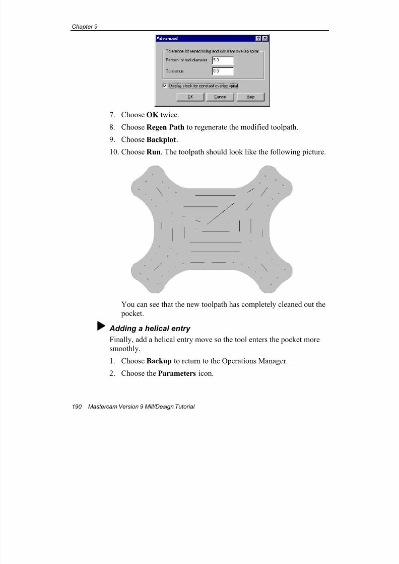
7/18/2019 V9 Mill-Design Tutorial (metric).pdf
http://slidepdf.com/reader/full/v9-mill-design-tutorial-metricpdf 202/453
Chapter 9
190 Mastercam Version 9 Mill/Design Tutorial
7. Choose OK twice.
8. Choose Regen Path to regenerate the modified toolpath.
9. Choose Backplot.
10. Choose Run. The toolpath should look like the following picture.
You can see that the new toolpath has completely cleaned out the
pocket.
Adding a helical entry
Finally, add a helical entry move so the tool enters the pocket more
smoothly.
1. Choose Backup to return to the Operations Manager.
2. Choose the Parameters icon.
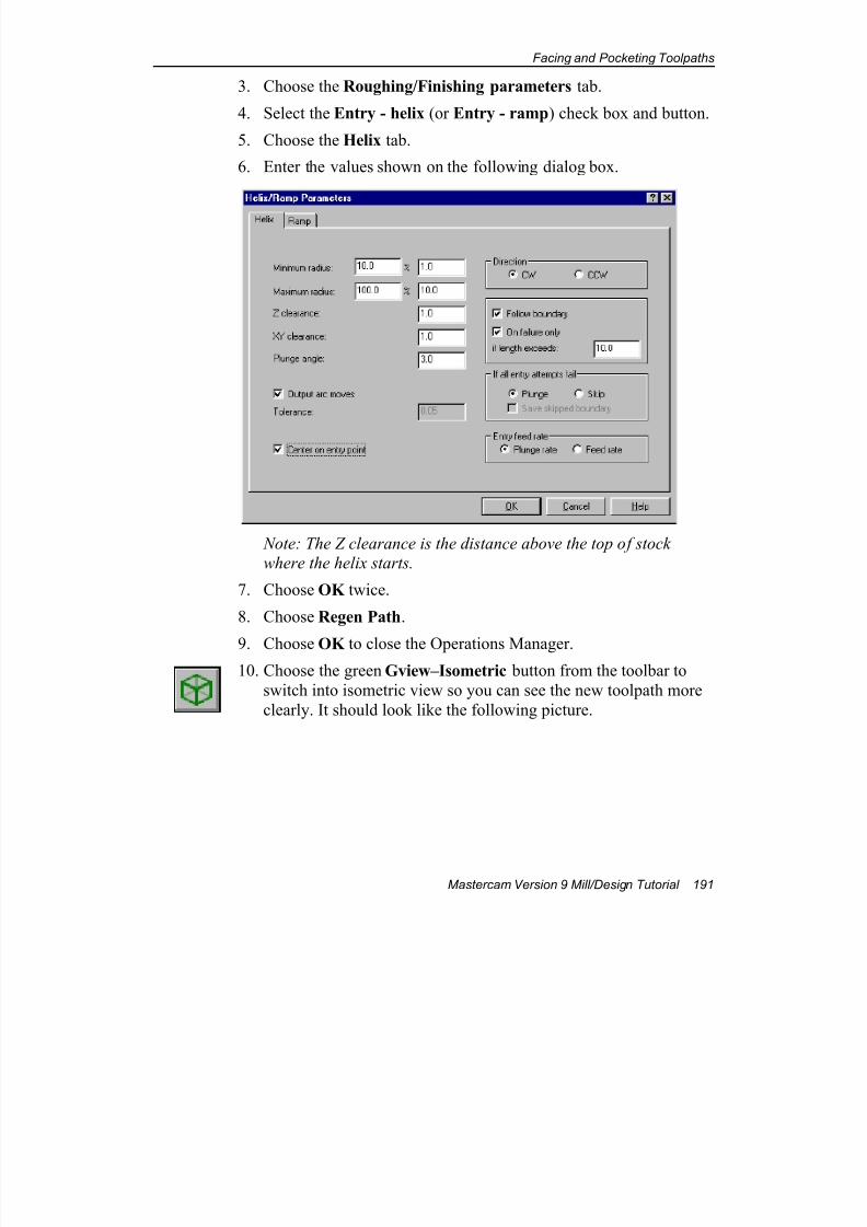
7/18/2019 V9 Mill-Design Tutorial (metric).pdf
http://slidepdf.com/reader/full/v9-mill-design-tutorial-metricpdf 203/453
Facing and Pocketing Toolpaths
Mastercam Version 9 Mill/Design Tutorial 191
3. Choose the Roughing/Finishing parameters tab.
4. Select the Entry - helix (or Entry - ramp) check box and button.
5. Choose the Helix tab.
6. Enter the values shown on the following dialog box.
Note: The Z clearance is the distance above the top of stock
where the helix starts.
7. Choose OK twice.
8. Choose Regen Path.
9. Choose OK to close the Operations Manager.10. Choose the green Gview–Isometric button from the toolbar to
switch into isometric view so you can see the new toolpath more
clearly. It should look like the following picture.
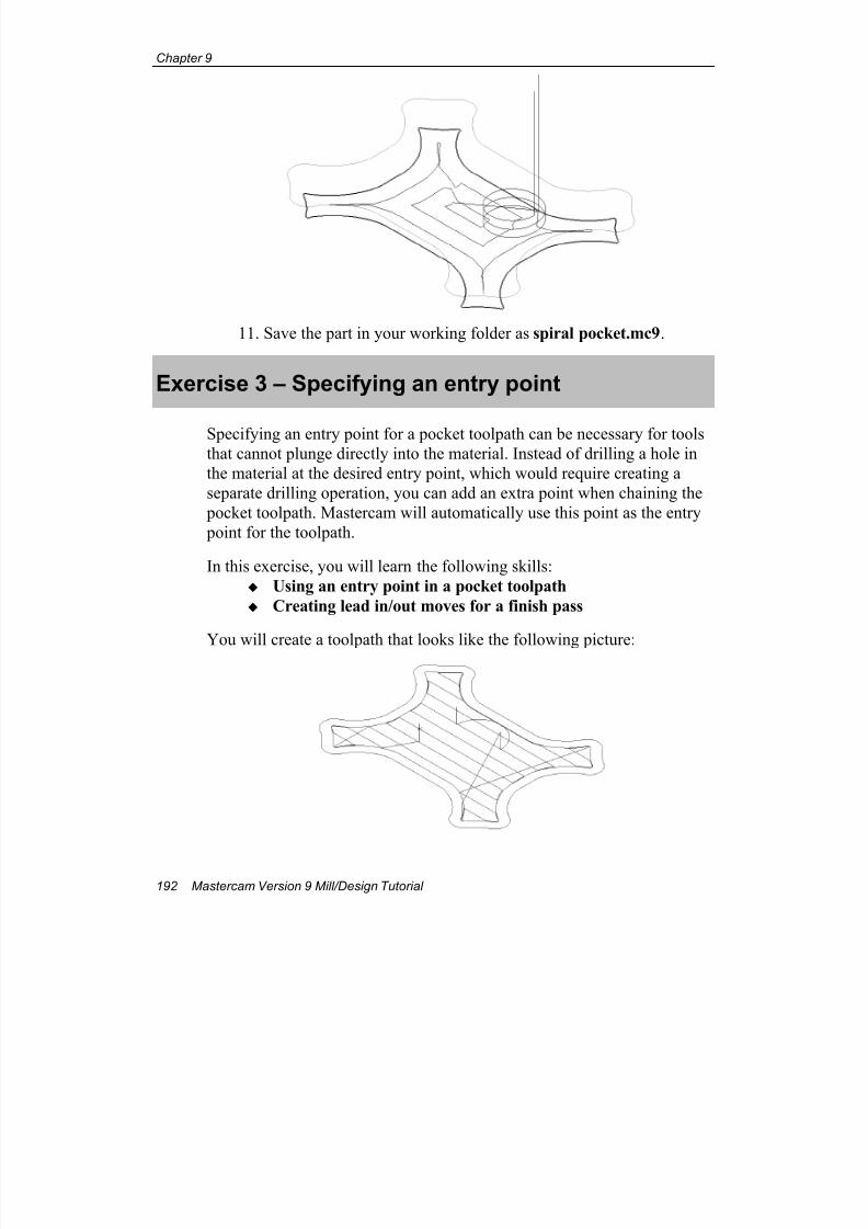
7/18/2019 V9 Mill-Design Tutorial (metric).pdf
http://slidepdf.com/reader/full/v9-mill-design-tutorial-metricpdf 204/453
Chapter 9
192 Mastercam Version 9 Mill/Design Tutorial
11. Save the part in your working folder as spiral pocket.mc9.
Exercise 3 – Specifying an entry point
Specifying an entry point for a pocket toolpath can be necessary for toolsthat cannot plunge directly into the material. Instead of drilling a hole in
the material at the desired entry point, which would require creating a
separate drilling operation, you can add an extra point when chaining the
pocket toolpath. Mastercam will automatically use this point as the entry
point for the toolpath.
In this exercise, you will learn the following skills:
Using an entry point in a pocket toolpath
Creating lead in/out moves for a finish pass
You will create a toolpath that looks like the following picture:
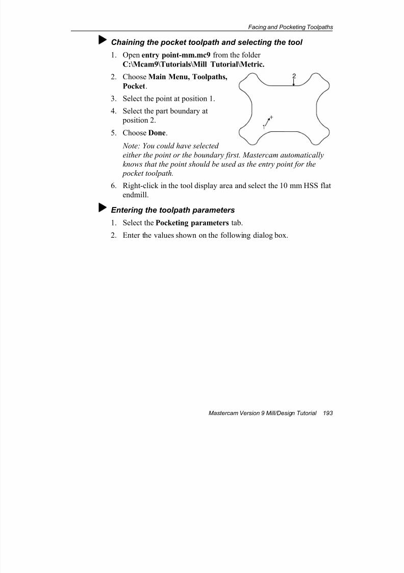
7/18/2019 V9 Mill-Design Tutorial (metric).pdf
http://slidepdf.com/reader/full/v9-mill-design-tutorial-metricpdf 205/453
Facing and Pocketing Toolpaths
Mastercam Version 9 Mill/Design Tutorial 193
Chaining the pocket toolpath and selecting the tool
1. Open entry point-mm.mc9 from the folder
C:\Mcam9\Tutorials\Mill Tutorial\Metric.
2. Choose Main Menu, Toolpaths,
Pocket.
3. Select the point at position 1.4. Select the part boundary at
position 2.
5. Choose Done.
Note: You could have selected
either the point or the boundary first. Mastercam automatically
knows that the point should be used as the entry point for the
pocket toolpath.
6. Right-click in the tool display area and select the 10 mm HSS flat
endmill.
Entering the toolpath parameters
1. Select the Pocketing parameters tab.
2. Enter the values shown on the following dialog box.
1
2
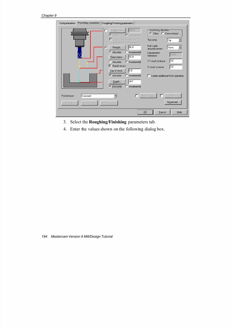
7/18/2019 V9 Mill-Design Tutorial (metric).pdf
http://slidepdf.com/reader/full/v9-mill-design-tutorial-metricpdf 206/453
Chapter 9
194 Mastercam Version 9 Mill/Design Tutorial
3. Select the Roughing/Finishing parameters tab.
4. Enter the values shown on the following dialog box.
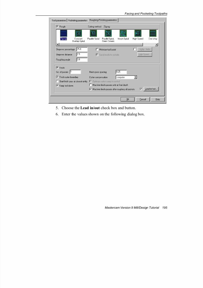
7/18/2019 V9 Mill-Design Tutorial (metric).pdf
http://slidepdf.com/reader/full/v9-mill-design-tutorial-metricpdf 207/453
Facing and Pocketing Toolpaths
Mastercam Version 9 Mill/Design Tutorial 195
5. Choose the Lead in/out check box and button.
6. Enter the values shown on the following dialog box.
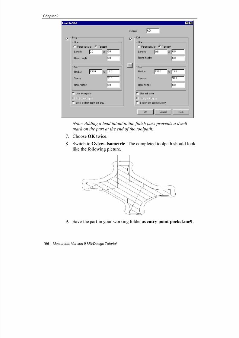
7/18/2019 V9 Mill-Design Tutorial (metric).pdf
http://slidepdf.com/reader/full/v9-mill-design-tutorial-metricpdf 208/453
Chapter 9
196 Mastercam Version 9 Mill/Design Tutorial
Note: Adding a lead in/out to the finish pass prevents a dwell
mark on the part at the end of the toolpath.
7. Choose OK twice.
8. Switch to Gview–Isometric. The completed toolpath should look
like the following picture.
9. Save the part in your working folder as entry point pocket.mc9.
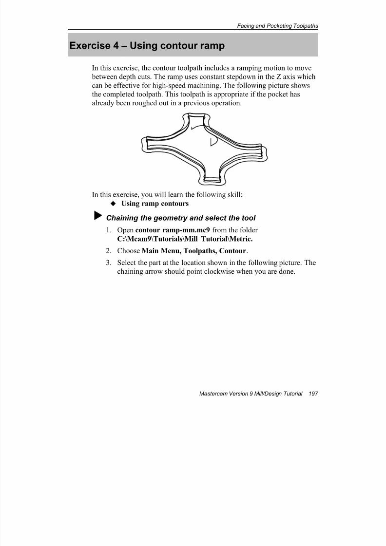
7/18/2019 V9 Mill-Design Tutorial (metric).pdf
http://slidepdf.com/reader/full/v9-mill-design-tutorial-metricpdf 209/453
Facing and Pocketing Toolpaths
Mastercam Version 9 Mill/Design Tutorial 197
Exercise 4 – Using contour ramp
In this exercise, the contour toolpath includes a ramping motion to move
between depth cuts. The ramp uses constant stepdown in the Z axis which
can be effective for high-speed machining. The following picture shows
the completed toolpath. This toolpath is appropriate if the pocket hasalready been roughed out in a previous operation.
In this exercise, you will learn the following skill:
Using ramp contours
Chaining the geometry and select the tool
1. Open contour ramp-mm.mc9 from the folder
C:\Mcam9\Tutorials\Mill Tutorial\Metric.
2. Choose Main Menu, Toolpaths, Contour.
3. Select the part at the location shown in the following picture. The
chaining arrow should point clockwise when you are done.
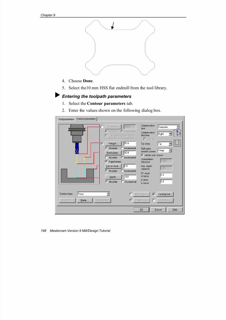
7/18/2019 V9 Mill-Design Tutorial (metric).pdf
http://slidepdf.com/reader/full/v9-mill-design-tutorial-metricpdf 210/453
Chapter 9
198 Mastercam Version 9 Mill/Design Tutorial
4. Choose Done.
5. Select the10 mm HSS flat endmill from the tool library.
Entering the toolpath parameters
1. Select the Contour parameters tab.
2. Enter the values shown on the following dialog box.
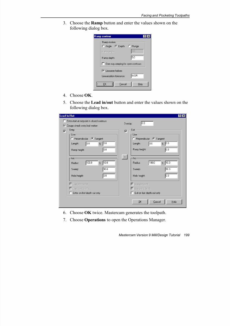
7/18/2019 V9 Mill-Design Tutorial (metric).pdf
http://slidepdf.com/reader/full/v9-mill-design-tutorial-metricpdf 211/453
Facing and Pocketing Toolpaths
Mastercam Version 9 Mill/Design Tutorial 199
3. Choose the Ramp button and enter the values shown on the
following dialog box.
4. Choose OK .
5. Choose the Lead in/out button and enter the values shown on the
following dialog box.
6. Choose OK twice. Mastercam generates the toolpath.
7. Choose Operations to open the Operations Manager.
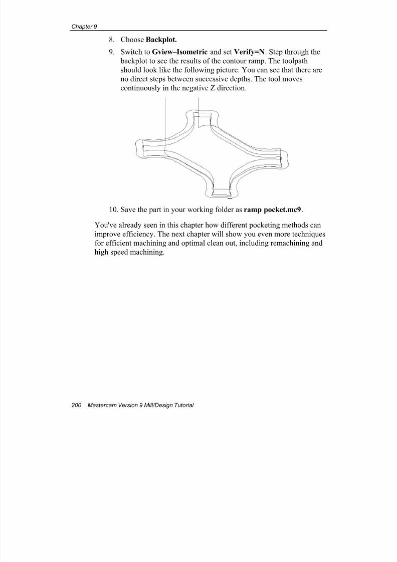
7/18/2019 V9 Mill-Design Tutorial (metric).pdf
http://slidepdf.com/reader/full/v9-mill-design-tutorial-metricpdf 212/453
Chapter 9
200 Mastercam Version 9 Mill/Design Tutorial
8. Choose Backplot.
9. Switch to Gview–Isometric and set Verify=N. Step through the
backplot to see the results of the contour ramp. The toolpath
should look like the following picture. You can see that there are
no direct steps between successive depths. The tool moves
continuously in the negative Z direction.
10. Save the part in your working folder as ramp pocket.mc9.
You've already seen in this chapter how different pocketing methods can
improve efficiency. The next chapter will show you even more techniques
for efficient machining and optimal clean out, including remachining and
high speed machining.
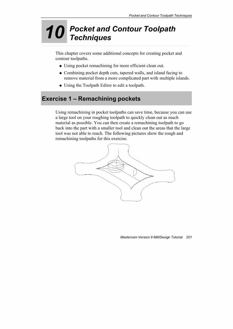
7/18/2019 V9 Mill-Design Tutorial (metric).pdf
http://slidepdf.com/reader/full/v9-mill-design-tutorial-metricpdf 213/453
Pocket and Contour Toolpath Techniques
Mastercam Version 9 Mill/Design Tutorial 201
10 Pocket and Contour ToolpathTechniques
This chapter covers some additional concepts for creating pocket and
contour toolpaths.
Using pocket remachining for more efficient clean out.
Combining pocket depth cuts, tapered walls, and island facing to
remove material from a more complicated part with multiple islands.
Using the Toolpath Editor to edit a toolpath.
Exercise 1 – Remachining pockets
Using remachining in pocket toolpaths can save time, because you can use
a large tool on your roughing toolpath to quickly clean out as much
material as possible. You can then create a remachining toolpath to go
back into the part with a smaller tool and clean out the areas that the large
tool was not able to reach. The following pictures show the rough and
remachining toolpaths for this exercise.
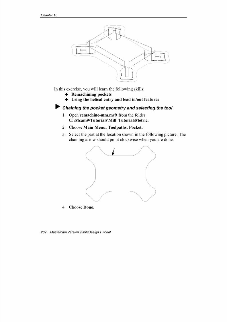
7/18/2019 V9 Mill-Design Tutorial (metric).pdf
http://slidepdf.com/reader/full/v9-mill-design-tutorial-metricpdf 214/453
Chapter 10
202 Mastercam Version 9 Mill/Design Tutorial
In this exercise, you will learn the following skills:
Remachining pockets
Using the helical entry and lead in/out features
Chaining the pocket geometry and selecting the tool
1. Open remachine-mm.mc9 from the folder
C:\Mcam9\Tutorials\Mill Tutorial\Metric.
2. Choose Main Menu, Toolpaths, Pocket.
3. Select the part at the location shown in the following picture. The
chaining arrow should point clockwise when you are done.
4. Choose Done.
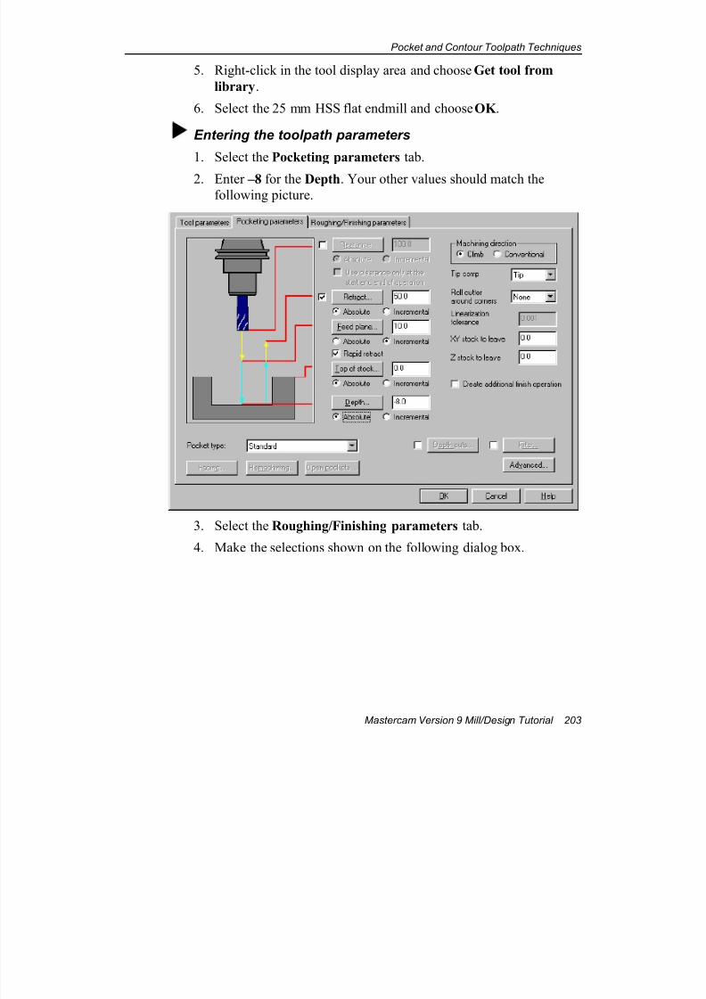
7/18/2019 V9 Mill-Design Tutorial (metric).pdf
http://slidepdf.com/reader/full/v9-mill-design-tutorial-metricpdf 215/453
Pocket and Contour Toolpath Techniques
Mastercam Version 9 Mill/Design Tutorial 203
5. Right-click in the tool display area and choose Get tool from
library.
6. Select the 25 mm HSS flat endmill and choose OK .
Entering the toolpath parameters
1. Select the Pocketing parameters tab.
2. Enter –8 for the Depth. Your other values should match thefollowing picture.
3. Select the Roughing/Finishing parameters tab.
4. Make the selections shown on the following dialog box.
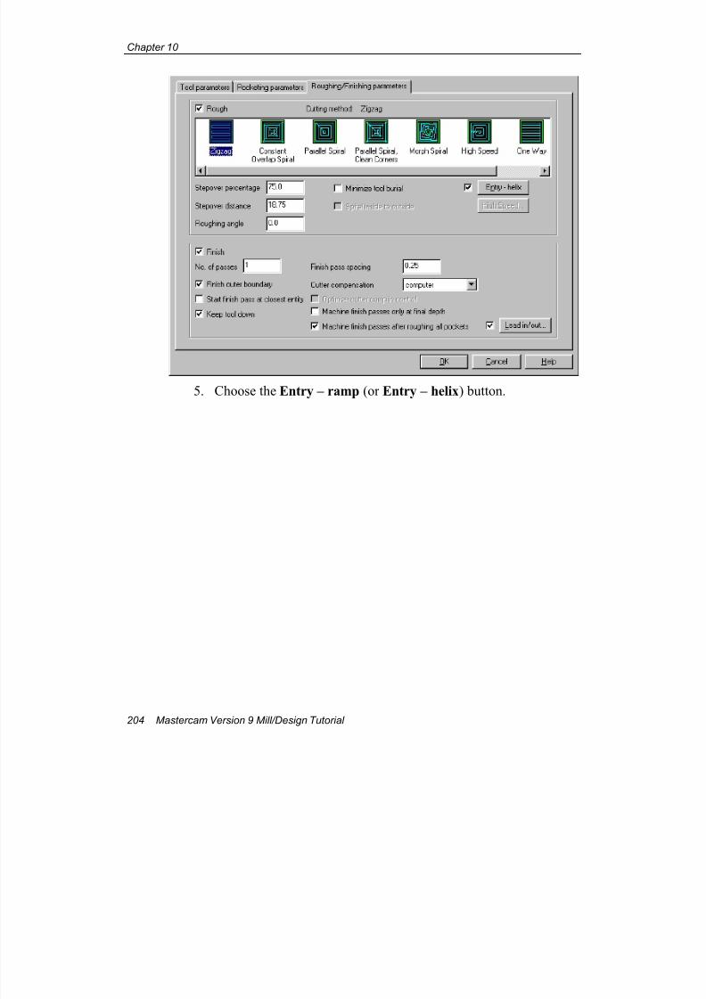
7/18/2019 V9 Mill-Design Tutorial (metric).pdf
http://slidepdf.com/reader/full/v9-mill-design-tutorial-metricpdf 216/453
Chapter 10
204 Mastercam Version 9 Mill/Design Tutorial
5. Choose the Entry – ramp (or Entry – helix) button.
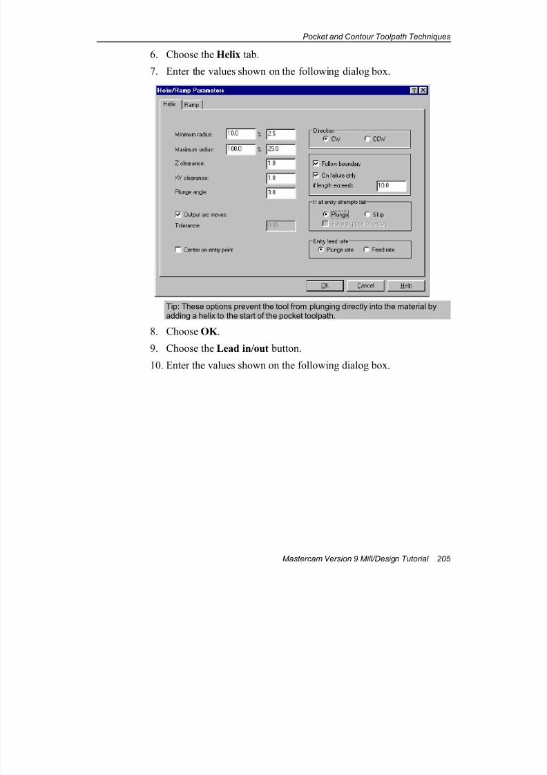
7/18/2019 V9 Mill-Design Tutorial (metric).pdf
http://slidepdf.com/reader/full/v9-mill-design-tutorial-metricpdf 217/453
Pocket and Contour Toolpath Techniques
Mastercam Version 9 Mill/Design Tutorial 205
6. Choose the Helix tab.
7. Enter the values shown on the following dialog box.
Tip: These options prevent the tool from plunging directly into the material byadding a helix to the start of the pocket toolpath.
8. Choose OK .
9. Choose the Lead in/out button.
10. Enter the values shown on the following dialog box.
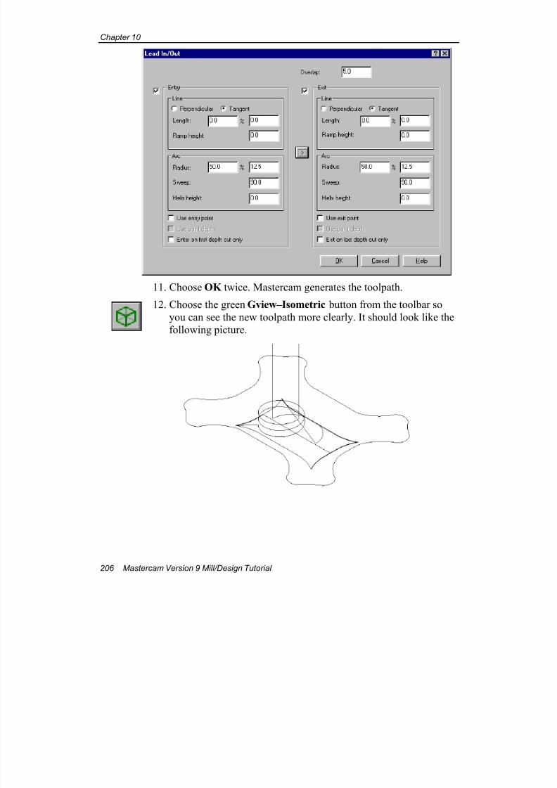
7/18/2019 V9 Mill-Design Tutorial (metric).pdf
http://slidepdf.com/reader/full/v9-mill-design-tutorial-metricpdf 218/453
Chapter 10
206 Mastercam Version 9 Mill/Design Tutorial
11. Choose OK twice. Mastercam generates the toolpath.
12. Choose the green Gview–Isometric button from the toolbar so
you can see the new toolpath more clearly. It should look like the
following picture.
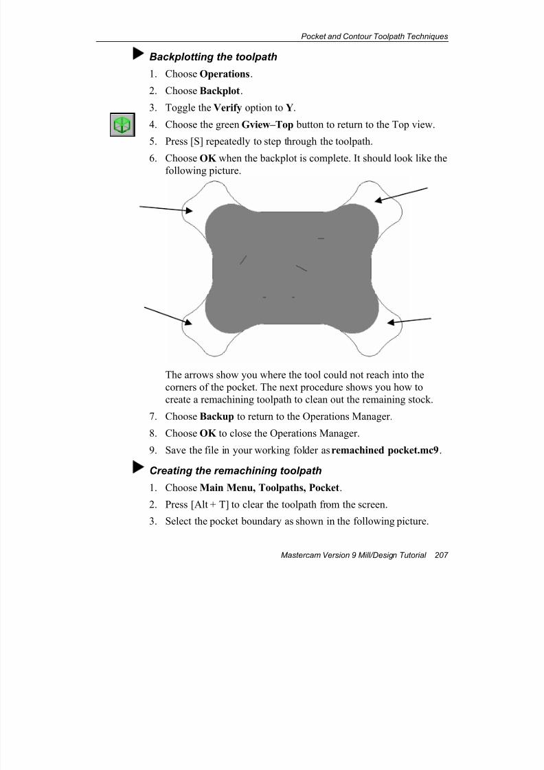
7/18/2019 V9 Mill-Design Tutorial (metric).pdf
http://slidepdf.com/reader/full/v9-mill-design-tutorial-metricpdf 219/453
Pocket and Contour Toolpath Techniques
Mastercam Version 9 Mill/Design Tutorial 207
Backplotting the toolpath
1. Choose Operations.
2. Choose Backplot.
3. Toggle the Verify option to Y.
4. Choose the green Gview–Top button to return to the Top view.
5. Press [S] repeatedly to step through the toolpath.
6. Choose OK when the backplot is complete. It should look like the
following picture.
The arrows show you where the tool could not reach into the
corners of the pocket. The next procedure shows you how to
create a remachining toolpath to clean out the remaining stock.7. Choose Backup to return to the Operations Manager.
8. Choose OK to close the Operations Manager.
9. Save the file in your working folder as remachined pocket.mc9.
Creating the remachining toolpath
1. Choose Main Menu, Toolpaths, Pocket.
2. Press [Alt + T] to clear the toolpath from the screen.
3. Select the pocket boundary as shown in the following picture.
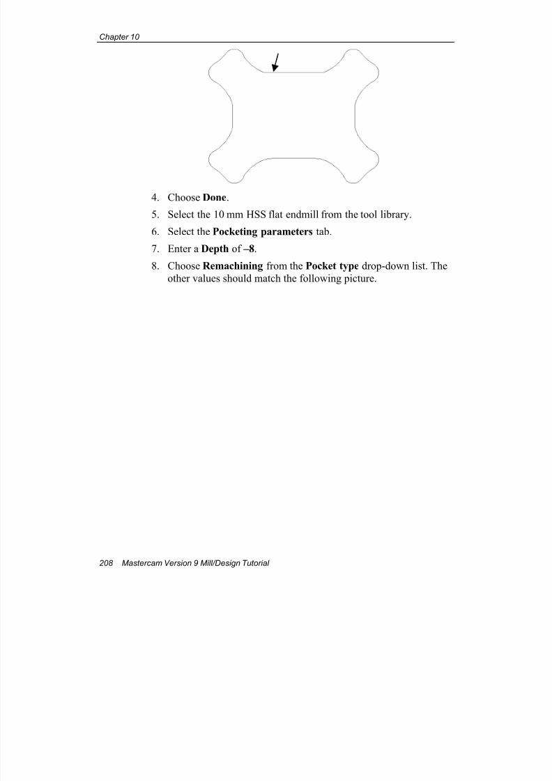
7/18/2019 V9 Mill-Design Tutorial (metric).pdf
http://slidepdf.com/reader/full/v9-mill-design-tutorial-metricpdf 220/453
Chapter 10
208 Mastercam Version 9 Mill/Design Tutorial
4. Choose Done.
5. Select the 10 mm HSS flat endmill from the tool library.
6. Select the Pocketing parameters tab.
7. Enter a Depth of –8.
8. Choose Remachining from the Pocket type drop-down list. The
other values should match the following picture.
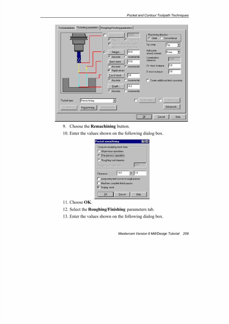
7/18/2019 V9 Mill-Design Tutorial (metric).pdf
http://slidepdf.com/reader/full/v9-mill-design-tutorial-metricpdf 221/453
Pocket and Contour Toolpath Techniques
Mastercam Version 9 Mill/Design Tutorial 209
9. Choose the Remachining button.
10. Enter the values shown on the following dialog box.
11. Choose OK .
12. Select the Roughing/Finishing parameters tab.
13. Enter the values shown on the following dialog box.
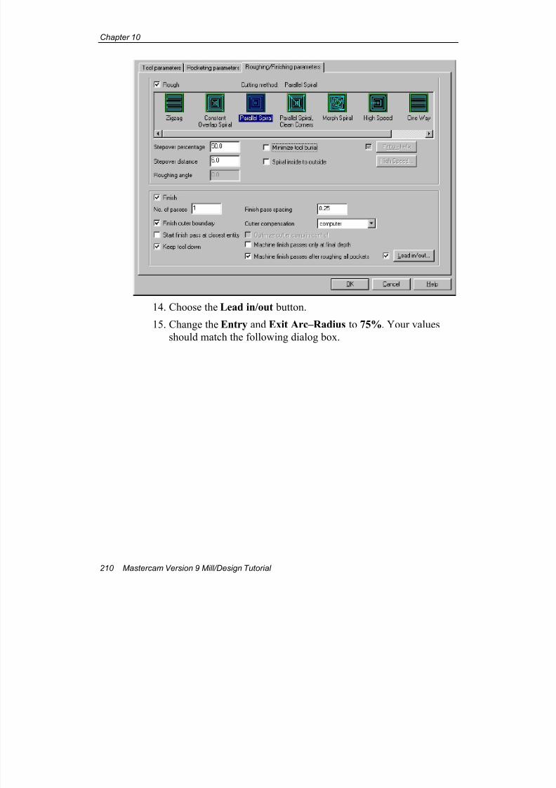
7/18/2019 V9 Mill-Design Tutorial (metric).pdf
http://slidepdf.com/reader/full/v9-mill-design-tutorial-metricpdf 222/453
Chapter 10
210 Mastercam Version 9 Mill/Design Tutorial
14. Choose the Lead in/out button.
15. Change the Entry and Exit Arc–Radius to 75%. Your values
should match the following dialog box.
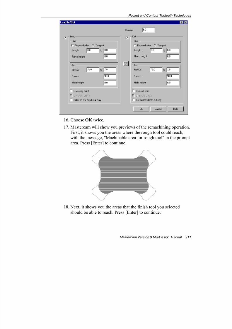
7/18/2019 V9 Mill-Design Tutorial (metric).pdf
http://slidepdf.com/reader/full/v9-mill-design-tutorial-metricpdf 223/453
Pocket and Contour Toolpath Techniques
Mastercam Version 9 Mill/Design Tutorial 211
16. Choose OK twice.
17. Mastercam will show you previews of the remachining operation.
First, it shows you the areas where the rough tool could reach,
with the message, "Machinable area for rough tool" in the prompt
area. Press [Enter] to continue.
18. Next, it shows you the areas that the finish tool you selected
should be able to reach. Press [Enter] to continue.
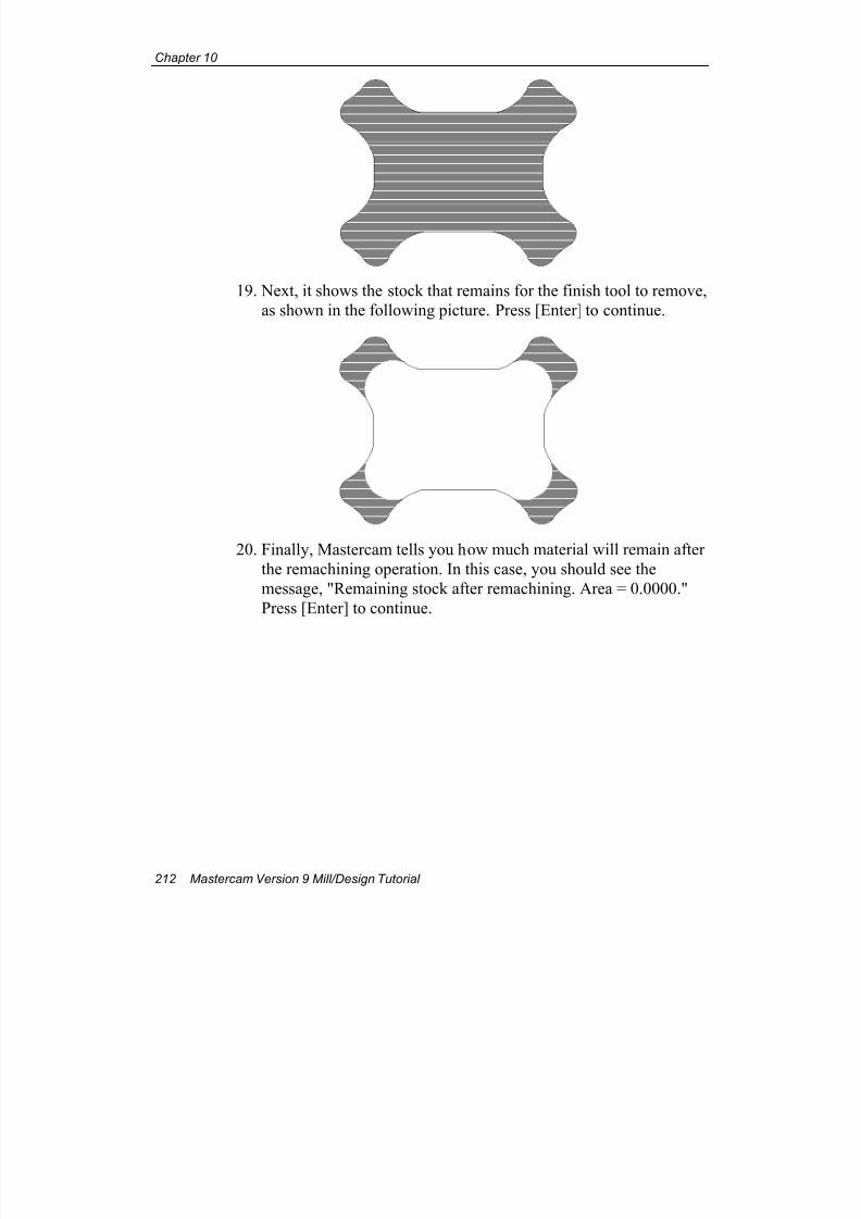
7/18/2019 V9 Mill-Design Tutorial (metric).pdf
http://slidepdf.com/reader/full/v9-mill-design-tutorial-metricpdf 224/453
Chapter 10
212 Mastercam Version 9 Mill/Design Tutorial
19. Next, it shows the stock that remains for the finish tool to remove,
as shown in the following picture. Press [Enter] to continue.
20. Finally, Mastercam tells you how much material will remain after
the remachining operation. In this case, you should see the
message, "Remaining stock after remachining. Area = 0.0000."
Press [Enter] to continue.
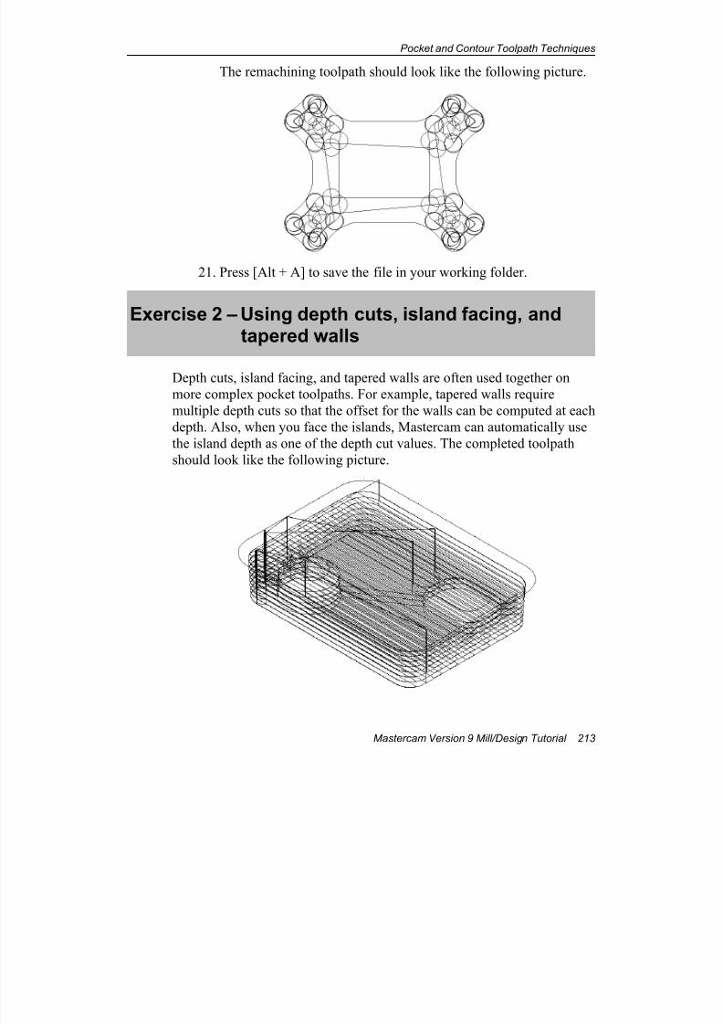
7/18/2019 V9 Mill-Design Tutorial (metric).pdf
http://slidepdf.com/reader/full/v9-mill-design-tutorial-metricpdf 225/453
Pocket and Contour Toolpath Techniques
Mastercam Version 9 Mill/Design Tutorial 213
The remachining toolpath should look like the following picture.
21. Press [Alt + A] to save the file in your working folder.
Exercise 2 – Using depth cuts, island facing, andtapered walls
Depth cuts, island facing, and tapered walls are often used together on
more complex pocket toolpaths. For example, tapered walls require
multiple depth cuts so that the offset for the walls can be computed at each
depth. Also, when you face the islands, Mastercam can automatically use
the island depth as one of the depth cut values. The completed toolpath
should look like the following picture.
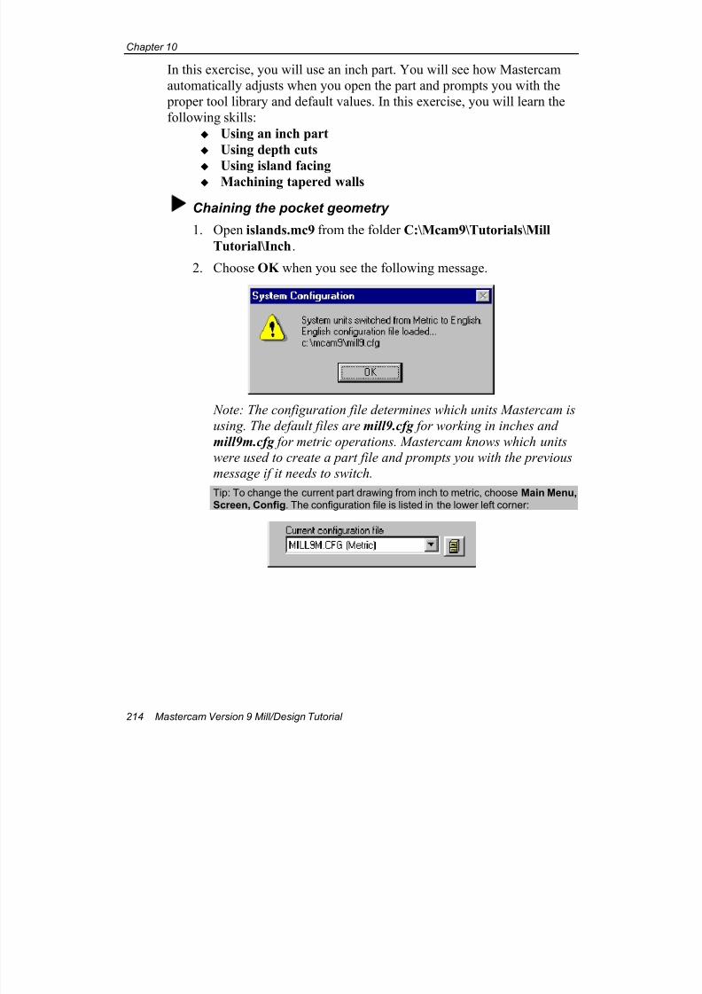
7/18/2019 V9 Mill-Design Tutorial (metric).pdf
http://slidepdf.com/reader/full/v9-mill-design-tutorial-metricpdf 226/453
Chapter 10
214 Mastercam Version 9 Mill/Design Tutorial
In this exercise, you will use an inch part. You will see how Mastercam
automatically adjusts when you open the part and prompts you with the
proper tool library and default values. In this exercise, you will learn the
following skills:
Using an inch part
Using depth cuts
Using island facing
Machining tapered walls
Chaining the pocket geometry
1. Open islands.mc9 from the folder C:\Mcam9\Tutorials\Mill
Tutorial\Inch.
2. Choose OK when you see the following message.
Note: The configuration file determines which units Mastercam is
using. The default files are mill9.cfg for working in inches and
mill9m.cfg for metric operations. Mastercam knows which units
were used to create a part file and prompts you with the previous
message if it needs to switch.
Tip: To change the current part drawing from inch to metric, choose Main Menu,
Screen, Config. The configuration file is listed in the lower left corner:
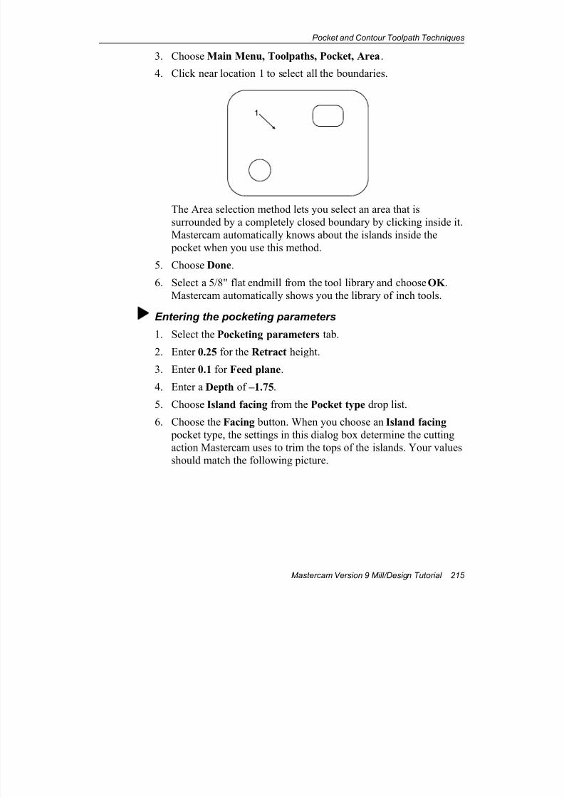
7/18/2019 V9 Mill-Design Tutorial (metric).pdf
http://slidepdf.com/reader/full/v9-mill-design-tutorial-metricpdf 227/453
Pocket and Contour Toolpath Techniques
Mastercam Version 9 Mill/Design Tutorial 215
3. Choose Main Menu, Toolpaths, Pocket, Area.
4. Click near location 1 to select all the boundaries.
1
The Area selection method lets you select an area that is
surrounded by a completely closed boundary by clicking inside it.
Mastercam automatically knows about the islands inside the
pocket when you use this method.
5. Choose Done.
6. Select a 5/8" flat endmill from the tool library and choose OK .Mastercam automatically shows you the library of inch tools.
Entering the pocketing parameters
1. Select the Pocketing parameters tab.
2. Enter 0.25 for the Retract height.
3. Enter 0.1 for Feed plane.
4. Enter a Depth of –1.75.
5. Choose Island facing from the Pocket type drop list.
6. Choose the Facing button. When you choose an Island facing pocket type, the settings in this dialog box determine the cutting
action Mastercam uses to trim the tops of the islands. Your values
should match the following picture.
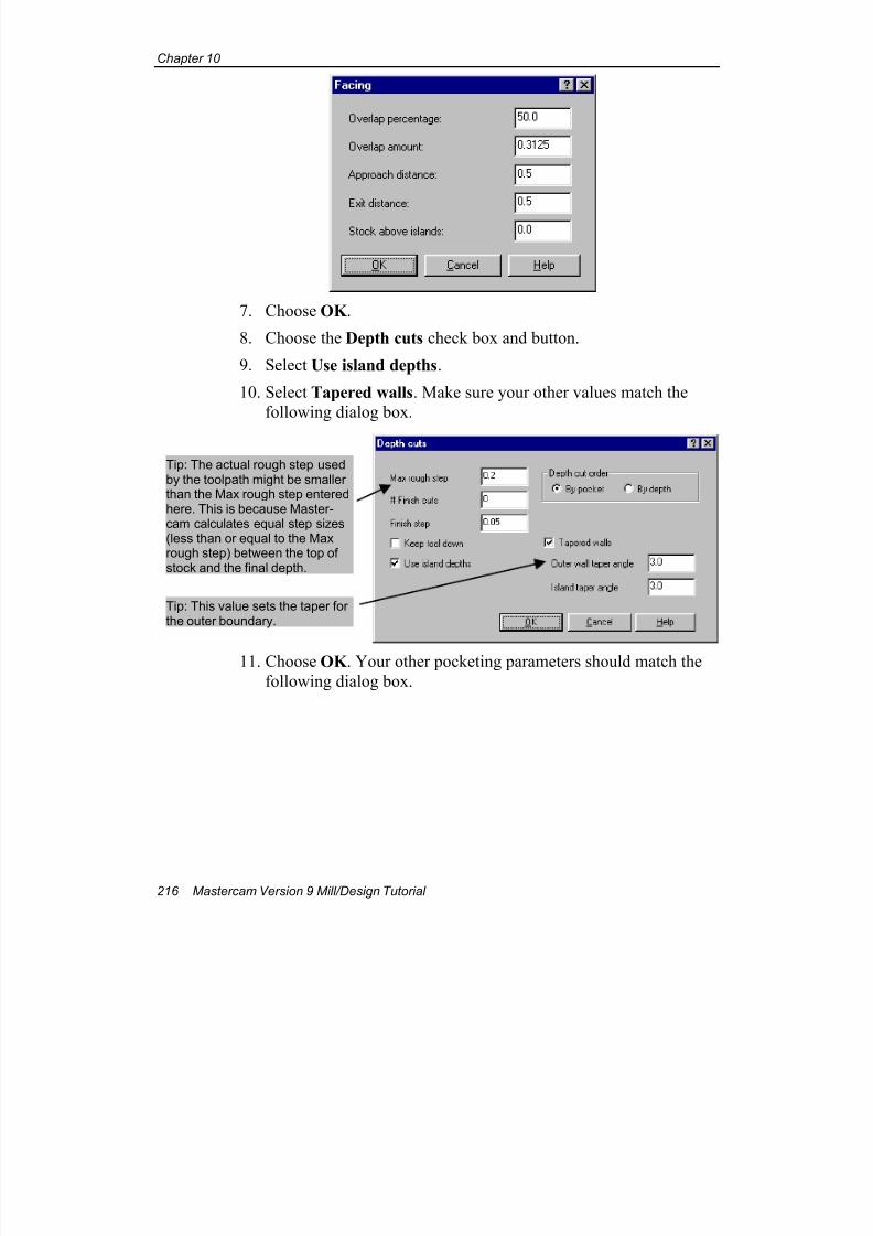
7/18/2019 V9 Mill-Design Tutorial (metric).pdf
http://slidepdf.com/reader/full/v9-mill-design-tutorial-metricpdf 228/453
Chapter 10
216 Mastercam Version 9 Mill/Design Tutorial
7. Choose OK .
8. Choose the Depth cuts check box and button.
9. Select Use island depths.
10. Select Tapered walls. Make sure your other values match the
following dialog box.
11. Choose OK . Your other pocketing parameters should match the
following dialog box.
Tip: The actual rough step usedby the toolpath might be smallerthan the Max rough step enteredhere. This is because Master-cam calculates equal step sizes(less than or equal to the Maxrough step) between the top ofstock and the final depth.
Tip: This value sets the taper forthe outer boundary.
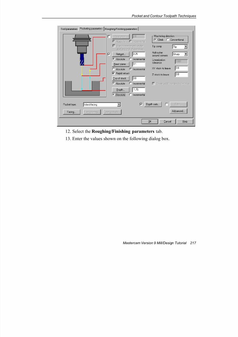
7/18/2019 V9 Mill-Design Tutorial (metric).pdf
http://slidepdf.com/reader/full/v9-mill-design-tutorial-metricpdf 229/453
Pocket and Contour Toolpath Techniques
Mastercam Version 9 Mill/Design Tutorial 217
12. Select the Roughing/Finishing parameters tab.
13. Enter the values shown on the following dialog box.
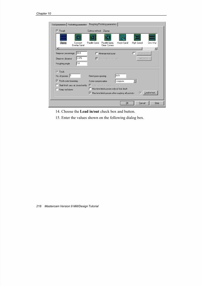
7/18/2019 V9 Mill-Design Tutorial (metric).pdf
http://slidepdf.com/reader/full/v9-mill-design-tutorial-metricpdf 230/453
Chapter 10
218 Mastercam Version 9 Mill/Design Tutorial
14. Choose the Lead in/out check box and button.
15. Enter the values shown on the following dialog box.
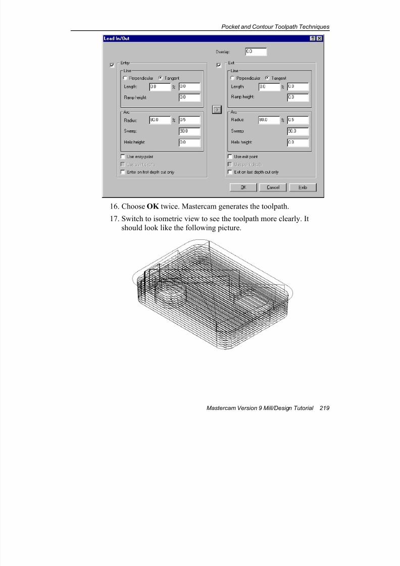
7/18/2019 V9 Mill-Design Tutorial (metric).pdf
http://slidepdf.com/reader/full/v9-mill-design-tutorial-metricpdf 231/453
Pocket and Contour Toolpath Techniques
Mastercam Version 9 Mill/Design Tutorial 219
16. Choose OK twice. Mastercam generates the toolpath.
17. Switch to isometric view to see the toolpath more clearly. It
should look like the following picture.
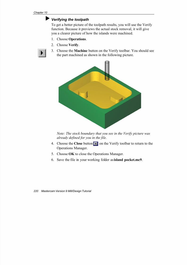
7/18/2019 V9 Mill-Design Tutorial (metric).pdf
http://slidepdf.com/reader/full/v9-mill-design-tutorial-metricpdf 232/453
Chapter 10
220 Mastercam Version 9 Mill/Design Tutorial
Verifying the toolpath
To get a better picture of the toolpath results, you will use the Verify
function. Because it previews the actual stock removal, it will give
you a clearer picture of how the islands were machined.
1. Choose Operations.
2. Choose Verify.3. Choose the Machine button on the Verify toolbar. You should see
the part machined as shown in the following picture.
Note: The stock boundary that you see in the Verify picture was
already defined for you in the file.4. Choose the Close button on the Verify toolbar to return to the
Operations Manager.
5. Choose OK to close the Operations Manager.
6. Save the file in your working folder as island pocket.mc9.
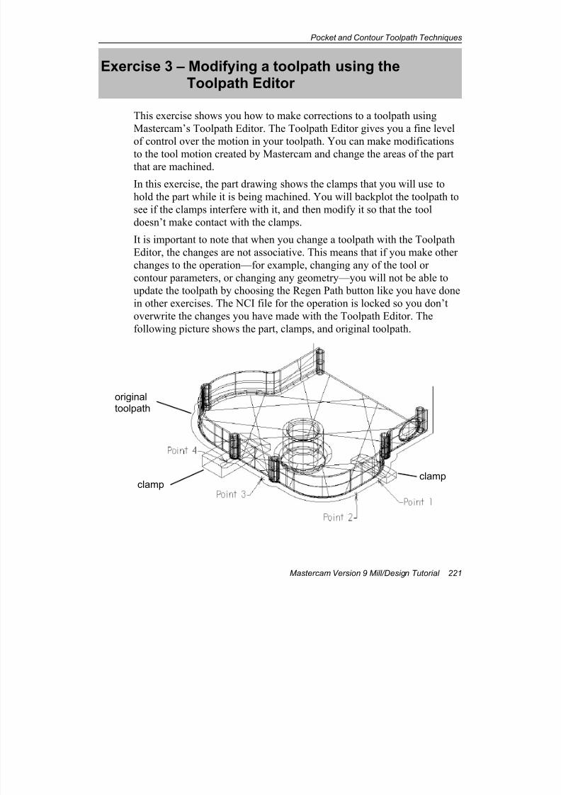
7/18/2019 V9 Mill-Design Tutorial (metric).pdf
http://slidepdf.com/reader/full/v9-mill-design-tutorial-metricpdf 233/453
Pocket and Contour Toolpath Techniques
Mastercam Version 9 Mill/Design Tutorial 221
Exercise 3 – Modifying a toolpath using theToolpath Editor
This exercise shows you how to make corrections to a toolpath using
Mastercam’s Toolpath Editor. The Toolpath Editor gives you a fine level
of control over the motion in your toolpath. You can make modificationsto the tool motion created by Mastercam and change the areas of the part
that are machined.
In this exercise, the part drawing shows the clamps that you will use to
hold the part while it is being machined. You will backplot the toolpath to
see if the clamps interfere with it, and then modify it so that the tool
doesn’t make contact with the clamps.
It is important to note that when you change a toolpath with the Toolpath
Editor, the changes are not associative. This means that if you make other
changes to the operation—for example, changing any of the tool or
contour parameters, or changing any geometry—you will not be able toupdate the toolpath by choosing the Regen Path button like you have done
in other exercises. The NCI file for the operation is locked so you don’t
overwrite the changes you have made with the Toolpath Editor. The
following picture shows the part, clamps, and original toolpath.
originaltoolpath
clampclamp
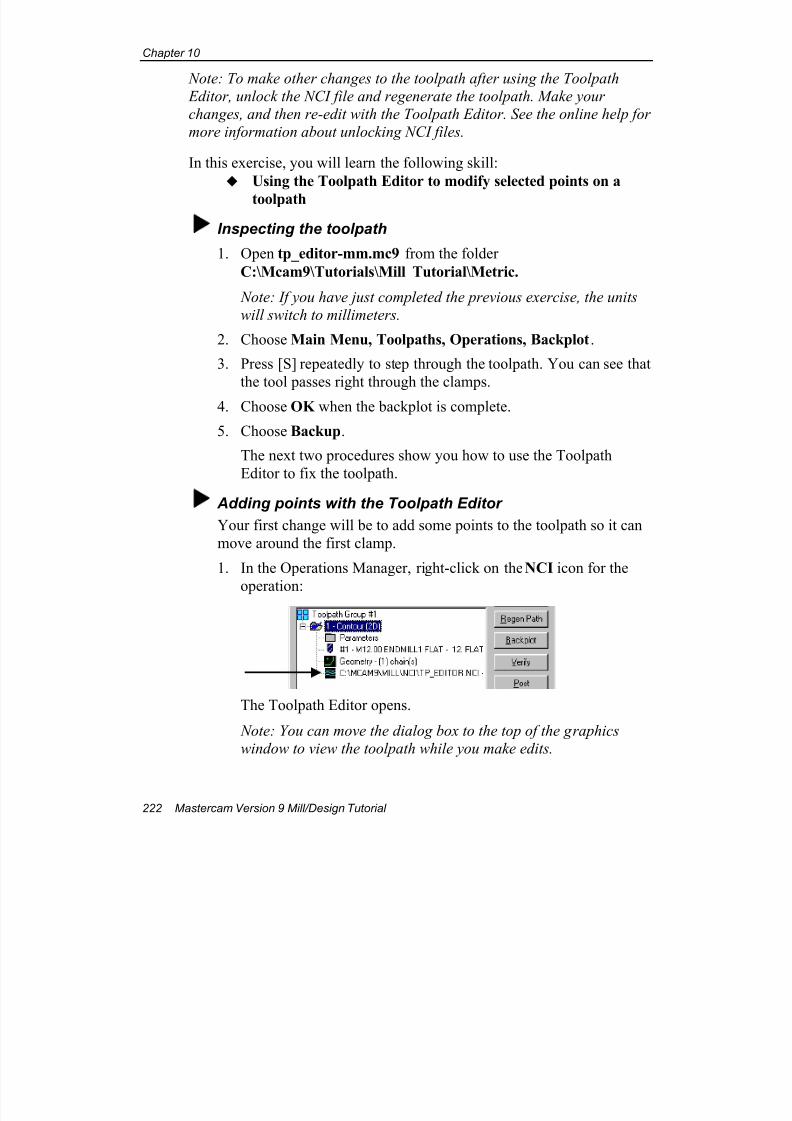
7/18/2019 V9 Mill-Design Tutorial (metric).pdf
http://slidepdf.com/reader/full/v9-mill-design-tutorial-metricpdf 234/453
Chapter 10
222 Mastercam Version 9 Mill/Design Tutorial
Note: To make other changes to the toolpath after using the Toolpath
Editor, unlock the NCI file and regenerate the toolpath. Make your
changes, and then re-edit with the Toolpath Editor. See the online help for
more information about unlocking NCI files.
In this exercise, you will learn the following skill:
Using the Toolpath Editor to modify selected points on a
toolpath
Inspecting the toolpath
1. Open tp_editor-mm.mc9 from the folder
C:\Mcam9\Tutorials\Mill Tutorial\Metric.
Note: If you have just completed the previous exercise, the units
will switch to millimeters.
2. Choose Main Menu, Toolpaths, Operations, Backplot.
3. Press [S] repeatedly to step through the toolpath. You can see that
the tool passes right through the clamps.
4. Choose OK when the backplot is complete.
5. Choose Backup.
The next two procedures show you how to use the Toolpath
Editor to fix the toolpath.
Adding points with the Toolpath Editor
Your first change will be to add some points to the toolpath so it can
move around the first clamp.
1. In the Operations Manager, right-click on the NCI icon for the
operation:
The Toolpath Editor opens.
Note: You can move the dialog box to the top of the graphics
window to view the toolpath while you make edits.
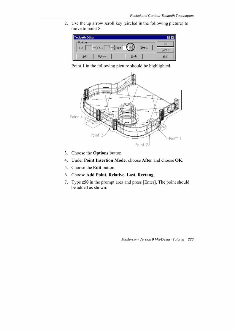
7/18/2019 V9 Mill-Design Tutorial (metric).pdf
http://slidepdf.com/reader/full/v9-mill-design-tutorial-metricpdf 235/453
Pocket and Contour Toolpath Techniques
Mastercam Version 9 Mill/Design Tutorial 223
2. Use the up arrow scroll key (circled in the following picture) to
move to point 8.
Point 1 in the following picture should be highlighted.
3. Choose the Options button.
4. Under Point Insertion Mode, choose After and choose OK .
5. Choose the Edit button.
6. Choose Add Point, Relative, Last, Rectang.
7. Type z50 in the prompt area and press [Enter]. The point should
be added as shown:
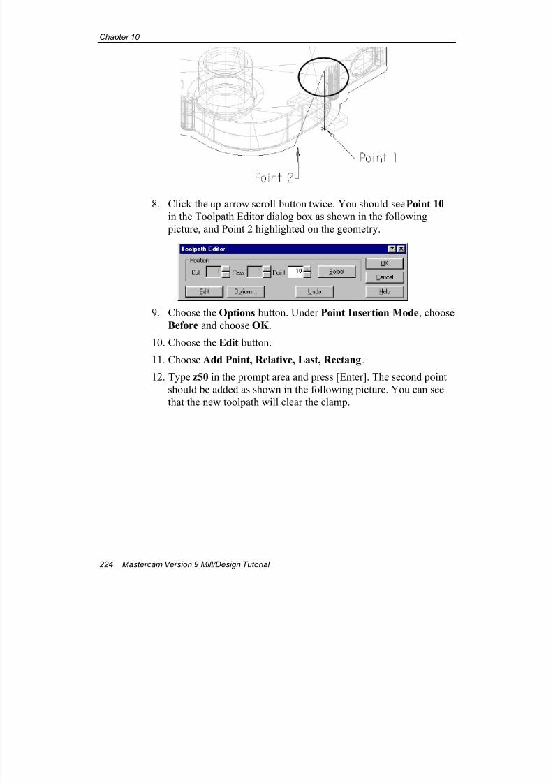
7/18/2019 V9 Mill-Design Tutorial (metric).pdf
http://slidepdf.com/reader/full/v9-mill-design-tutorial-metricpdf 236/453
Chapter 10
224 Mastercam Version 9 Mill/Design Tutorial
8. Click the up arrow scroll button twice. You should see Point 10
in the Toolpath Editor dialog box as shown in the following
picture, and Point 2 highlighted on the geometry.
9. Choose the Options button. Under Point Insertion Mode, choose
Before and choose OK .
10. Choose the Edit button.
11. Choose Add Point, Relative, Last, Rectang.
12. Type z50 in the prompt area and press [Enter]. The second point
should be added as shown in the following picture. You can see
that the new toolpath will clear the clamp.
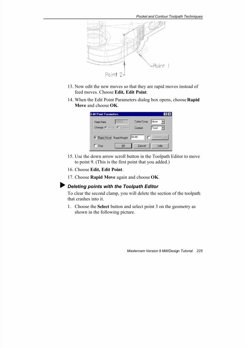
7/18/2019 V9 Mill-Design Tutorial (metric).pdf
http://slidepdf.com/reader/full/v9-mill-design-tutorial-metricpdf 237/453
Pocket and Contour Toolpath Techniques
Mastercam Version 9 Mill/Design Tutorial 225
13. Now edit the new moves so that they are rapid moves instead of
feed moves. Choose Edit, Edit Point.
14. When the Edit Point Parameters dialog box opens, choose Rapid
Move and choose OK .
15. Use the down arrow scroll button in the Toolpath Editor to move
to point 9. (This is the first point that you added.)
16. Choose Edit, Edit Point.
17. Choose Rapid Move again and choose OK .
Deleting points with the Toolpath Editor
To clear the second clamp, you will delete the section of the toolpath
that crashes into it.
1. Choose the Select button and select point 3 on the geometry as
shown in the following picture.
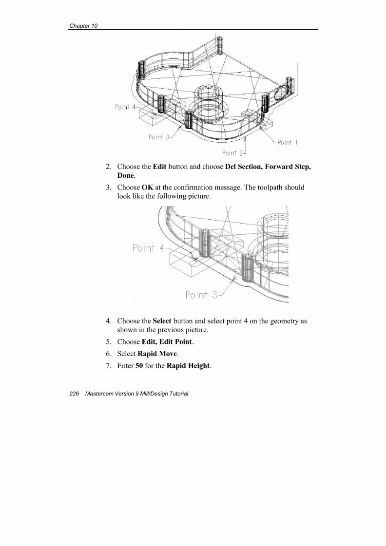
7/18/2019 V9 Mill-Design Tutorial (metric).pdf
http://slidepdf.com/reader/full/v9-mill-design-tutorial-metricpdf 238/453
Chapter 10
226 Mastercam Version 9 Mill/Design Tutorial
2. Choose the Edit button and choose Del Section, Forward Step,
Done.
3. ChooseOK
at the confirmation message. The toolpath should
look like the following picture.
4. Choose the Select button and select point 4 on the geometry as
shown in the previous picture.
5. Choose Edit, Edit Point.
6. Select Rapid Move.
7. Enter 50 for the Rapid Height.
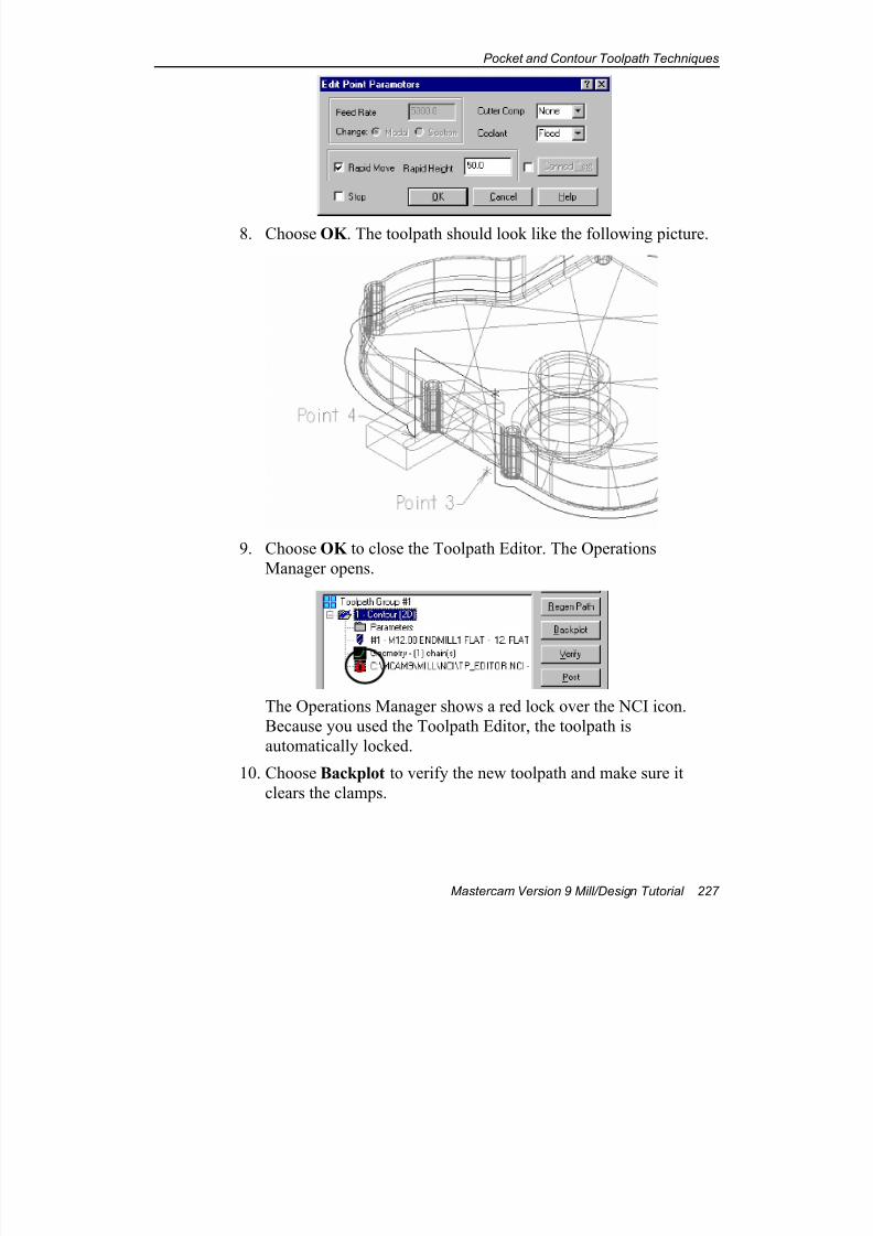
7/18/2019 V9 Mill-Design Tutorial (metric).pdf
http://slidepdf.com/reader/full/v9-mill-design-tutorial-metricpdf 239/453
Pocket and Contour Toolpath Techniques
Mastercam Version 9 Mill/Design Tutorial 227
8. Choose OK . The toolpath should look like the following picture.
9. Choose OK to close the Toolpath Editor. The Operations
Manager opens.
The Operations Manager shows a red lock over the NCI icon.
Because you used the Toolpath Editor, the toolpath is
automatically locked.
10. Choose Backplot to verify the new toolpath and make sure it
clears the clamps.
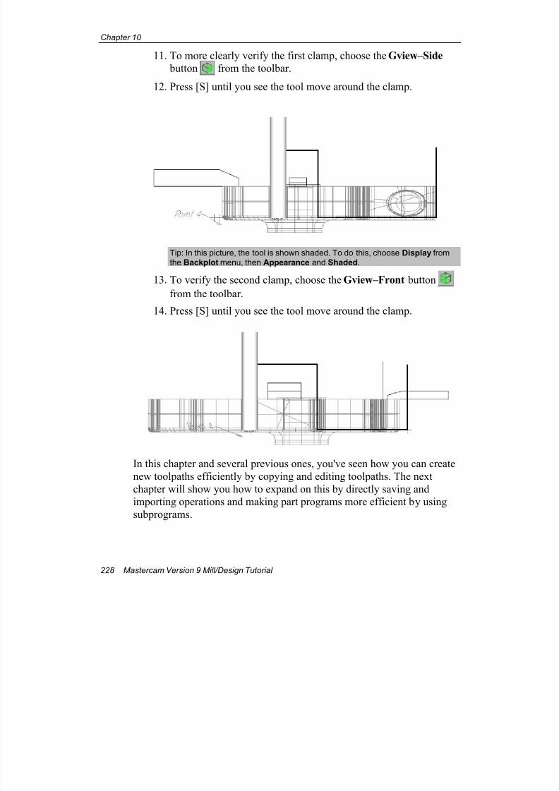
7/18/2019 V9 Mill-Design Tutorial (metric).pdf
http://slidepdf.com/reader/full/v9-mill-design-tutorial-metricpdf 240/453
Chapter 10
228 Mastercam Version 9 Mill/Design Tutorial
11. To more clearly verify the first clamp, choose the Gview–Side
button from the toolbar.
12. Press [S] until you see the tool move around the clamp.
Tip: In this picture, the tool is shown shaded. To do this, choose Display fromthe Backplot menu, then Appearance and Shaded.
13. To verify the second clamp, choose the Gview–Front buttonfrom the toolbar.
14. Press [S] until you see the tool move around the clamp.
In this chapter and several previous ones, you've seen how you can create
new toolpaths efficiently by copying and editing toolpaths. The next
chapter will show you how to expand on this by directly saving and
importing operations and making part programs more efficient by using
subprograms.
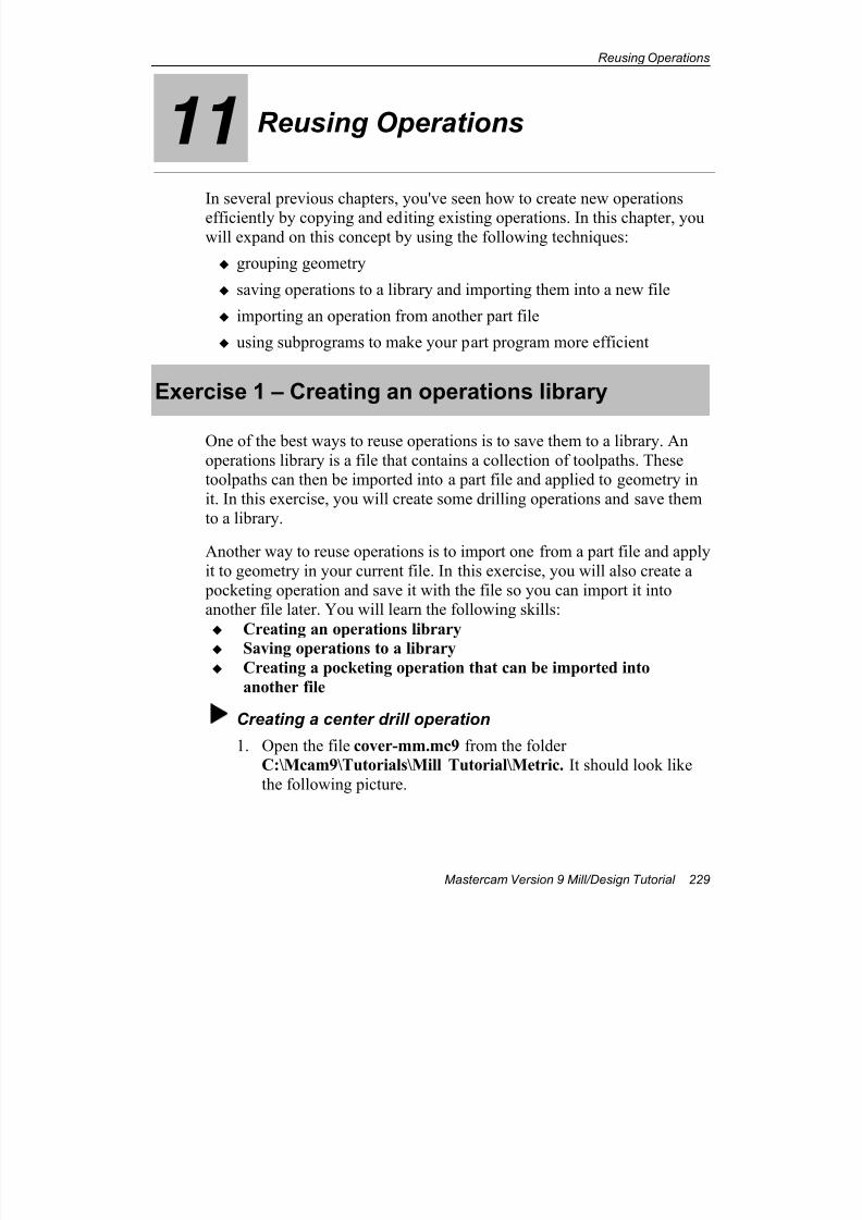
7/18/2019 V9 Mill-Design Tutorial (metric).pdf
http://slidepdf.com/reader/full/v9-mill-design-tutorial-metricpdf 241/453
Reusing Operations
Mastercam Version 9 Mill/Design Tutorial 229
11 Reusing Operations
In several previous chapters, you've seen how to create new operations
efficiently by copying and editing existing operations. In this chapter, youwill expand on this concept by using the following techniques:
grouping geometry
saving operations to a library and importing them into a new file
importing an operation from another part file
using subprograms to make your part program more efficient
Exercise 1 – Creating an operations library
One of the best ways to reuse operations is to save them to a library. An
operations library is a file that contains a collection of toolpaths. Thesetoolpaths can then be imported into a part file and applied to geometry in
it. In this exercise, you will create some drilling operations and save them
to a library.
Another way to reuse operations is to import one from a part file and apply
it to geometry in your current file. In this exercise, you will also create a
pocketing operation and save it with the file so you can import it intoanother file later. You will learn the following skills:
Creating an operations library
Saving operations to a library
Creating a pocketing operation that can be imported into
another file
Creating a center drill operation
1. Open the file cover-mm.mc9 from the folderC:\Mcam9\Tutorials\Mill Tutorial\Metric. It should look like
the following picture.
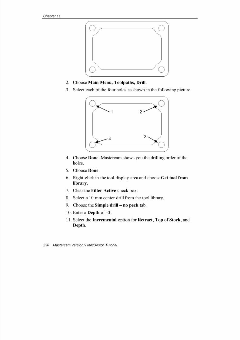
7/18/2019 V9 Mill-Design Tutorial (metric).pdf
http://slidepdf.com/reader/full/v9-mill-design-tutorial-metricpdf 242/453
Chapter 11
230 Mastercam Version 9 Mill/Design Tutorial
2. Choose Main Menu, Toolpaths, Drill.
3. Select each of the four holes as shown in the following picture.
4. Choose Done. Mastercam shows you the drilling order of theholes.
5. Choose Done.
6. Right-click in the tool display area and choose Get tool fromlibrary.
7. Clear the Filter Active check box.
8. Select a 10 mm center drill from the tool library.
9. Choose the Simple drill – no peck tab.
10. Enter a Depth of –2.
11. Select the Incremental option for Retract, Top of Stock , and
Depth.
1 2
34
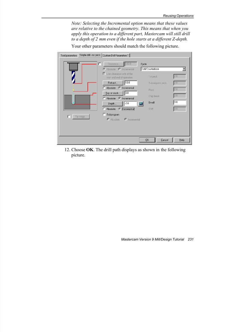
7/18/2019 V9 Mill-Design Tutorial (metric).pdf
http://slidepdf.com/reader/full/v9-mill-design-tutorial-metricpdf 243/453
Reusing Operations
Mastercam Version 9 Mill/Design Tutorial 231
Note: Selecting the Incremental option means that these valuesare relative to the chained geometry. This means that when you
apply this operation to a different part, Mastercam will still drill
to a depth of 2 mm even if the hole starts at a different Z-depth.
Your other parameters should match the following picture.
12. Choose OK . The drill path displays as shown in the following
picture.
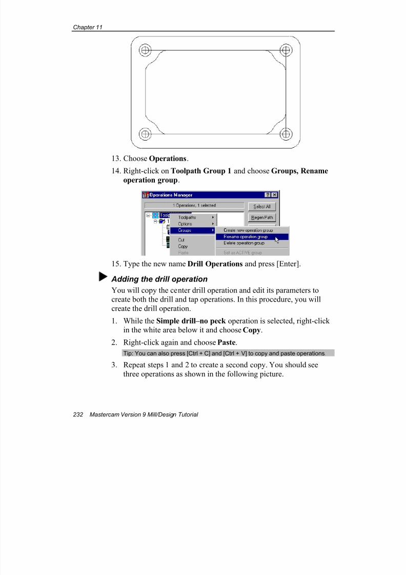
7/18/2019 V9 Mill-Design Tutorial (metric).pdf
http://slidepdf.com/reader/full/v9-mill-design-tutorial-metricpdf 244/453
Chapter 11
232 Mastercam Version 9 Mill/Design Tutorial
13. Choose Operations.
14. Right-click on Toolpath Group 1 and choose Groups, Rename
operation group.
15. Type the new name Drill Operations and press [Enter].
Adding the drill operation
You will copy the center drill operation and edit its parameters to
create both the drill and tap operations. In this procedure, you willcreate the drill operation.
1. While the Simple drill–no peck operation is selected, right-clickin the white area below it and choose Copy.
2. Right-click again and choose Paste.
Tip: You can also press [Ctrl + C] and [Ctrl + V] to copy and paste operations.
3. Repeat steps 1 and 2 to create a second copy. You should see
three operations as shown in the following picture.
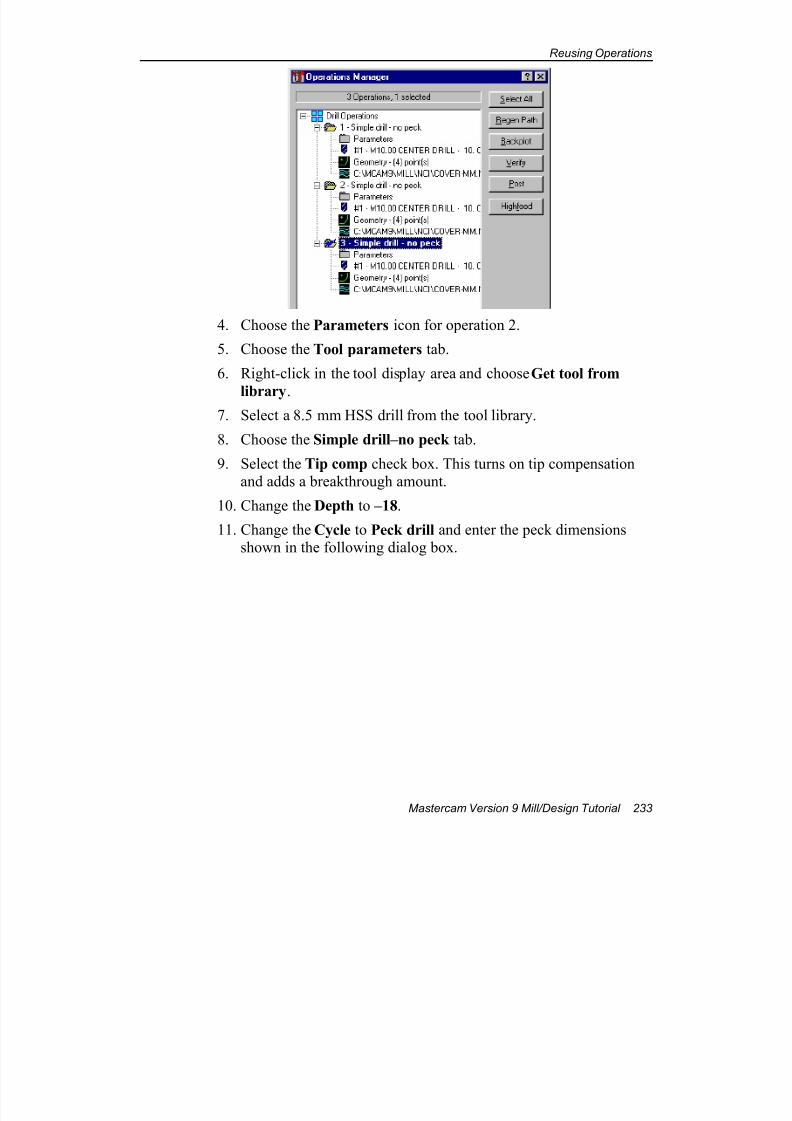
7/18/2019 V9 Mill-Design Tutorial (metric).pdf
http://slidepdf.com/reader/full/v9-mill-design-tutorial-metricpdf 245/453
Reusing Operations
Mastercam Version 9 Mill/Design Tutorial 233
4. Choose the Parameters icon for operation 2.
5. Choose the Tool parameters tab.
6. Right-click in the tool display area and choose Get tool from
library.7. Select a 8.5 mm HSS drill from the tool library.
8. Choose the Simple drill–no peck tab.
9. Select the Tip comp check box. This turns on tip compensationand adds a breakthrough amount.
10. Change the Depth to –18.
11. Change the Cycle to Peck drill and enter the peck dimensionsshown in the following dialog box.
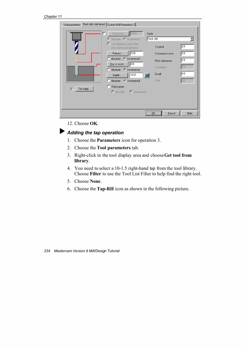
7/18/2019 V9 Mill-Design Tutorial (metric).pdf
http://slidepdf.com/reader/full/v9-mill-design-tutorial-metricpdf 246/453
Chapter 11
234 Mastercam Version 9 Mill/Design Tutorial
12. Choose OK .
Adding the tap operation
1. Choose the Parameters icon for operation 3.
2. Choose the Tool parameters tab.
3. Right-click in the tool display area and choose Get tool from
library.
4. You need to select a 10-1.5 right-hand tap from the tool library.Choose Filter to use the Tool List Filter to help find the right tool.
5. Choose None.6. Choose the Tap-RH icon as shown in the following picture.
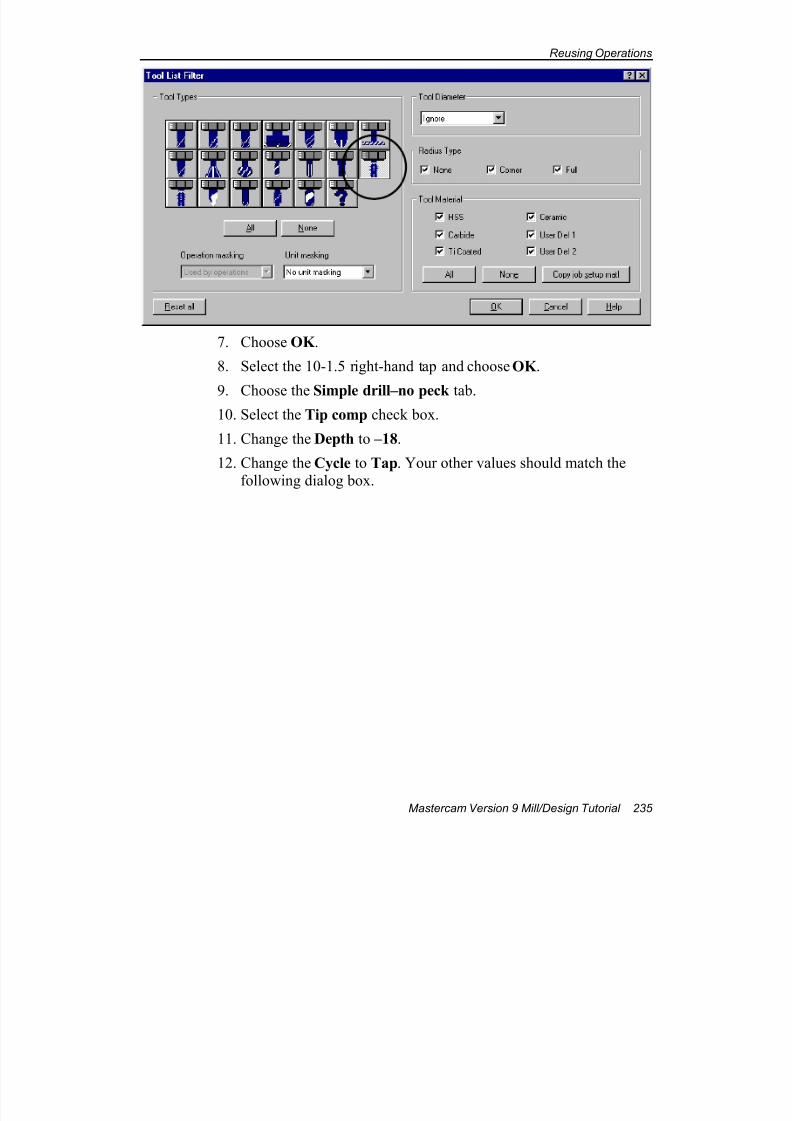
7/18/2019 V9 Mill-Design Tutorial (metric).pdf
http://slidepdf.com/reader/full/v9-mill-design-tutorial-metricpdf 247/453
Reusing Operations
Mastercam Version 9 Mill/Design Tutorial 235
7. Choose OK .
8. Select the 10-1.5 right-hand tap and choose OK .
9. Choose the Simple drill–no peck tab.10. Select the Tip comp check box.
11. Change the Depth to –18.
12. Change the Cycle to Tap. Your other values should match thefollowing dialog box.
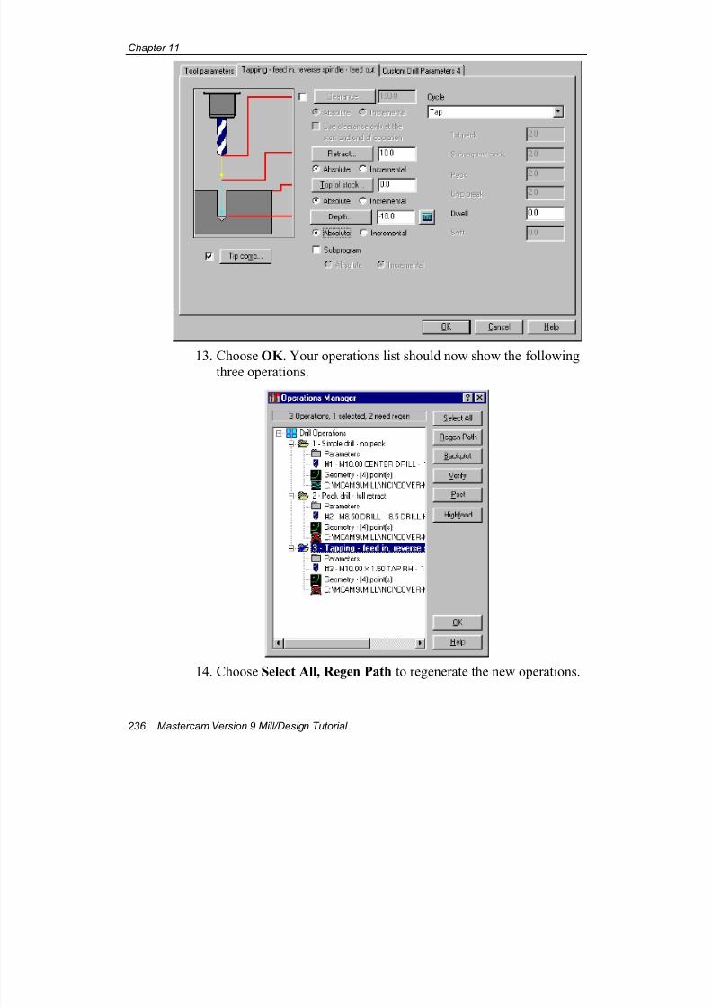
7/18/2019 V9 Mill-Design Tutorial (metric).pdf
http://slidepdf.com/reader/full/v9-mill-design-tutorial-metricpdf 248/453
Chapter 11
236 Mastercam Version 9 Mill/Design Tutorial
13. Choose OK . Your operations list should now show the followingthree operations.
14. Choose Select All, Regen Path to regenerate the new operations.
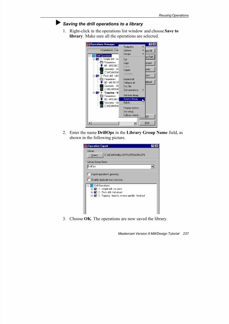
7/18/2019 V9 Mill-Design Tutorial (metric).pdf
http://slidepdf.com/reader/full/v9-mill-design-tutorial-metricpdf 249/453
Reusing Operations
Mastercam Version 9 Mill/Design Tutorial 237
Saving the drill operations to a library
1. Right-click in the operations list window and choose Save to
library. Make sure all the operations are selected.
2. Enter the name DrillOps in the Library Group Name field, asshown in the following picture.
3. Choose OK . The operations are now saved the library.
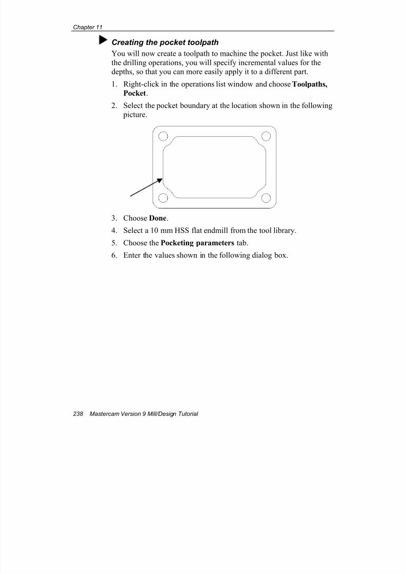
7/18/2019 V9 Mill-Design Tutorial (metric).pdf
http://slidepdf.com/reader/full/v9-mill-design-tutorial-metricpdf 250/453
Chapter 11
238 Mastercam Version 9 Mill/Design Tutorial
Creating the pocket toolpath
You will now create a toolpath to machine the pocket. Just like with
the drilling operations, you will specify incremental values for thedepths, so that you can more easily apply it to a different part.
1. Right-click in the operations list window and choose Toolpaths,
Pocket.
2. Select the pocket boundary at the location shown in the following picture.
3. Choose Done.
4. Select a 10 mm HSS flat endmill from the tool library.
5. Choose the Pocketing parameters tab.
6. Enter the values shown in the following dialog box.
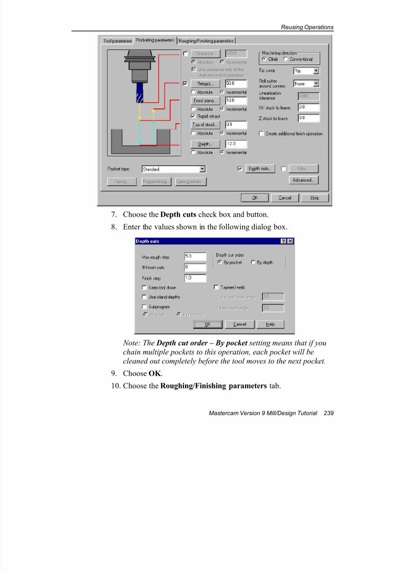
7/18/2019 V9 Mill-Design Tutorial (metric).pdf
http://slidepdf.com/reader/full/v9-mill-design-tutorial-metricpdf 251/453
Reusing Operations
Mastercam Version 9 Mill/Design Tutorial 239
7. Choose the Depth cuts check box and button.
8. Enter the values shown in the following dialog box.
Note: The Depth cut order – By pocket setting means that if you
chain multiple pockets to this operation, each pocket will be
cleaned out completely before the tool moves to the next pocket.
9. Choose OK .
10. Choose the Roughing/Finishing parameters tab.
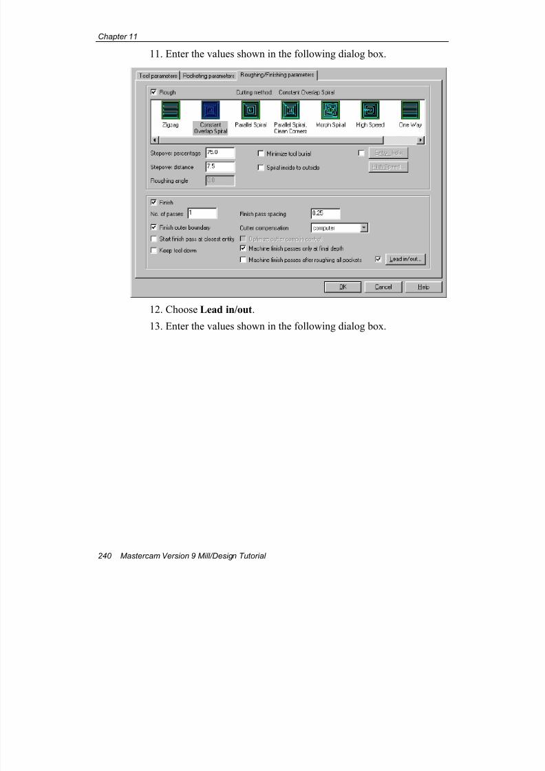
7/18/2019 V9 Mill-Design Tutorial (metric).pdf
http://slidepdf.com/reader/full/v9-mill-design-tutorial-metricpdf 252/453
Chapter 11
240 Mastercam Version 9 Mill/Design Tutorial
11. Enter the values shown in the following dialog box.
12. Choose Lead in/out.
13. Enter the values shown in the following dialog box.
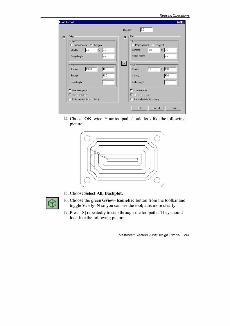
7/18/2019 V9 Mill-Design Tutorial (metric).pdf
http://slidepdf.com/reader/full/v9-mill-design-tutorial-metricpdf 253/453
Reusing Operations
Mastercam Version 9 Mill/Design Tutorial 241
14. Choose OK twice. Your toolpath should look like the following picture.
15. Choose Select All, Backplot.
16. Choose the green Gview–Isometric button from the toolbar and
toggle Verify=N so you can see the toolpaths more clearly.
17. Press [S] repeatedly to step through the toolpaths. They shouldlook like the following picture.
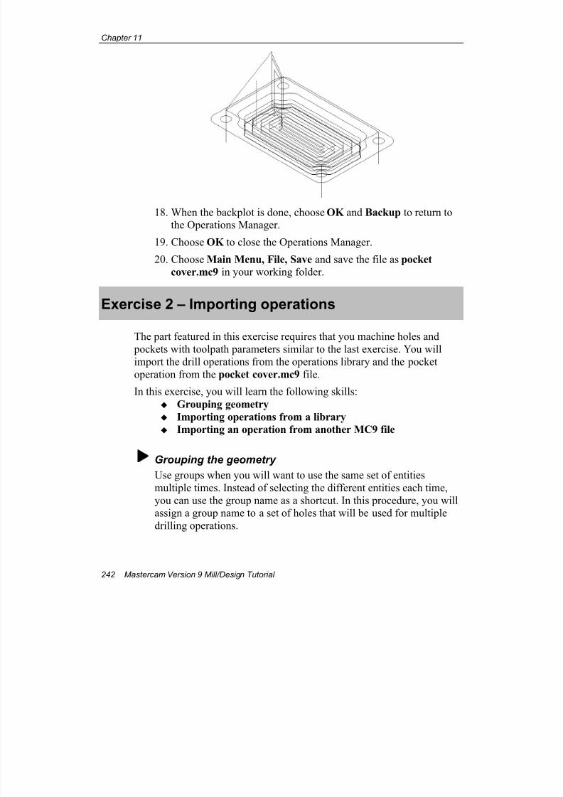
7/18/2019 V9 Mill-Design Tutorial (metric).pdf
http://slidepdf.com/reader/full/v9-mill-design-tutorial-metricpdf 254/453
Chapter 11
242 Mastercam Version 9 Mill/Design Tutorial
18. When the backplot is done, choose OK and Backup to return tothe Operations Manager.
19. Choose OK to close the Operations Manager.
20. Choose Main Menu, File, Save and save the file as pocket
cover.mc9 in your working folder.
Exercise 2 – Importing operations
The part featured in this exercise requires that you machine holes and
pockets with toolpath parameters similar to the last exercise. You will
import the drill operations from the operations library and the pocket
operation from the pocket cover.mc9 file.
In this exercise, you will learn the following skills:
Grouping geometry
Importing operations from a library Importing an operation from another MC9 file
Grouping the geometry
Use groups when you will want to use the same set of entities
multiple times. Instead of selecting the different entities each time,
you can use the group name as a shortcut. In this procedure, you willassign a group name to a set of holes that will be used for multiple
drilling operations.
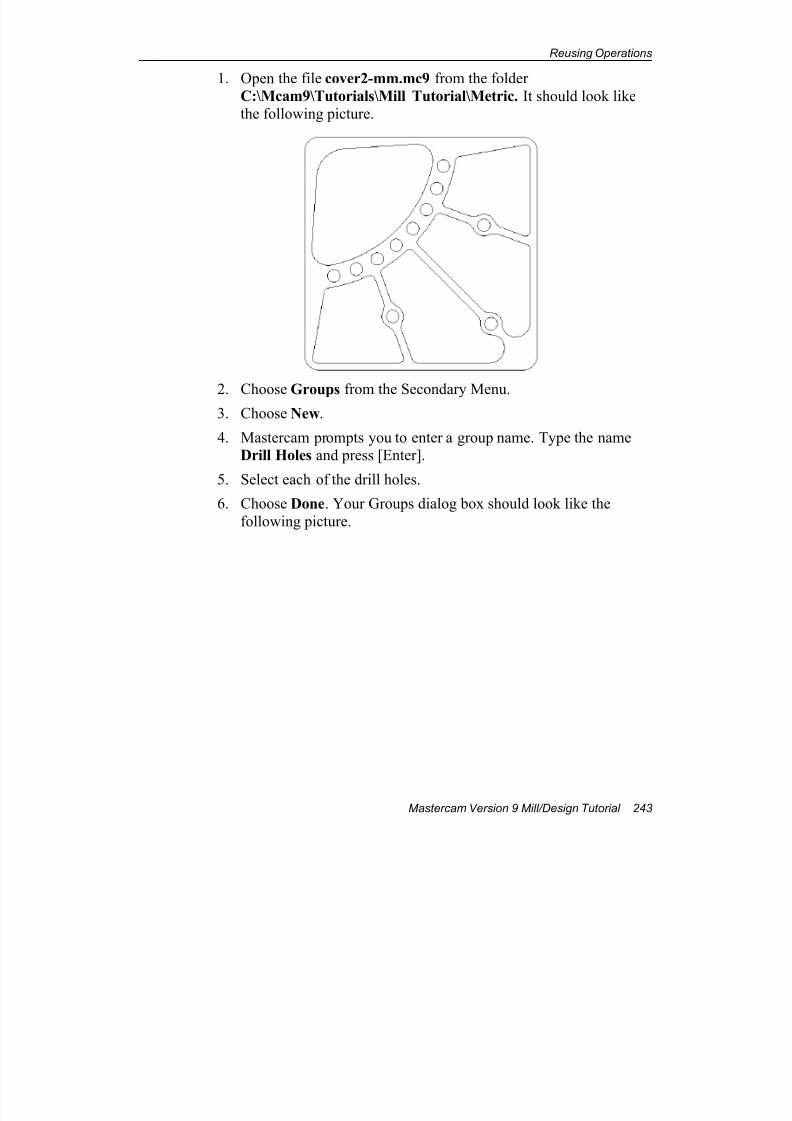
7/18/2019 V9 Mill-Design Tutorial (metric).pdf
http://slidepdf.com/reader/full/v9-mill-design-tutorial-metricpdf 255/453
Reusing Operations
Mastercam Version 9 Mill/Design Tutorial 243
1. Open the file cover2-mm.mc9 from the folder
C:\Mcam9\Tutorials\Mill Tutorial\Metric. It should look likethe following picture.
2. Choose Groups from the Secondary Menu.3. Choose New.
4. Mastercam prompts you to enter a group name. Type the nameDrill Holes and press [Enter].
5. Select each of the drill holes.
6. Choose Done. Your Groups dialog box should look like the
following picture.
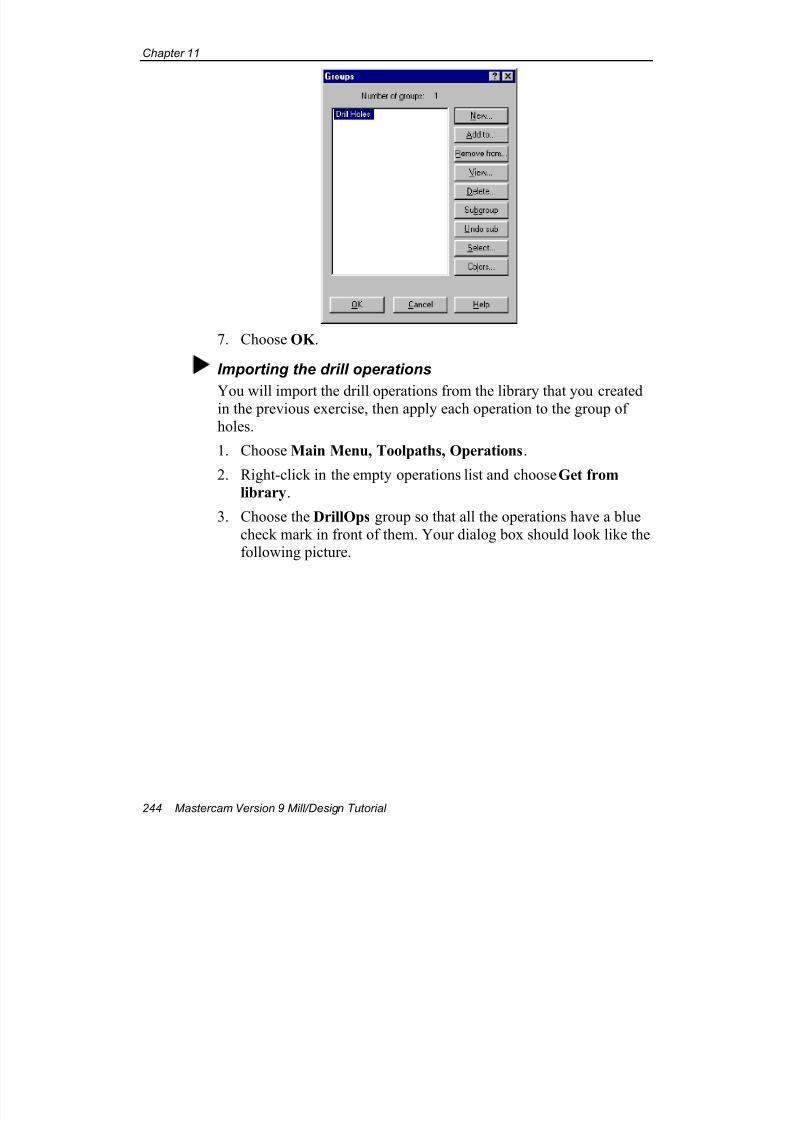
7/18/2019 V9 Mill-Design Tutorial (metric).pdf
http://slidepdf.com/reader/full/v9-mill-design-tutorial-metricpdf 256/453
Chapter 11
244 Mastercam Version 9 Mill/Design Tutorial
7. Choose OK .
Importing the drill operations
You will import the drill operations from the library that you createdin the previous exercise, then apply each operation to the group of
holes.
1. Choose Main Menu, Toolpaths, Operations.
2. Right-click in the empty operations list and choose Get from
library.
3. Choose the DrillOps group so that all the operations have a blue
check mark in front of them. Your dialog box should look like thefollowing picture.
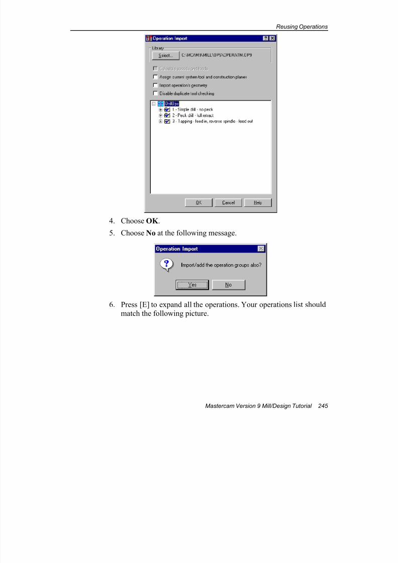
7/18/2019 V9 Mill-Design Tutorial (metric).pdf
http://slidepdf.com/reader/full/v9-mill-design-tutorial-metricpdf 257/453
Reusing Operations
Mastercam Version 9 Mill/Design Tutorial 245
4. Choose OK .
5. Choose No at the following message.
6. Press [E] to expand all the operations. Your operations list shouldmatch the following picture.
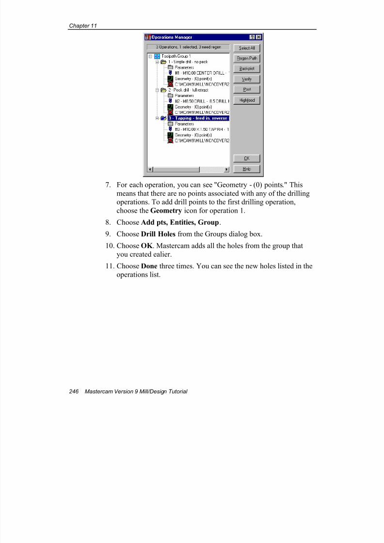
7/18/2019 V9 Mill-Design Tutorial (metric).pdf
http://slidepdf.com/reader/full/v9-mill-design-tutorial-metricpdf 258/453
Chapter 11
246 Mastercam Version 9 Mill/Design Tutorial
7. For each operation, you can see "Geometry - (0) points." This
means that there are no points associated with any of the drillingoperations. To add drill points to the first drilling operation,
choose the Geometry icon for operation 1.
8. Choose Add pts, Entities, Group.
9. Choose Drill Holes from the Groups dialog box.
10. Choose OK . Mastercam adds all the holes from the group thatyou created ealier.
11. Choose Done three times. You can see the new holes listed in theoperations list.
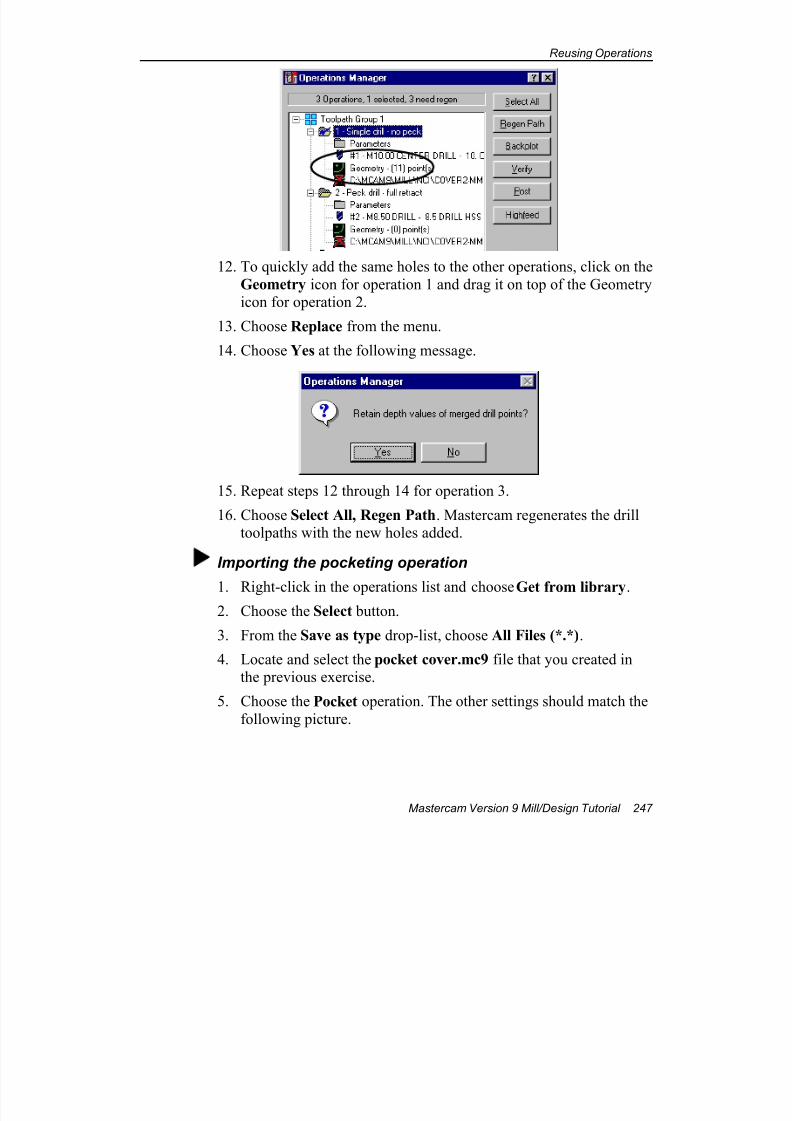
7/18/2019 V9 Mill-Design Tutorial (metric).pdf
http://slidepdf.com/reader/full/v9-mill-design-tutorial-metricpdf 259/453
Reusing Operations
Mastercam Version 9 Mill/Design Tutorial 247
12. To quickly add the same holes to the other operations, click on the
Geometry icon for operation 1 and drag it on top of the Geometryicon for operation 2.
13. Choose Replace from the menu.
14. Choose Yes at the following message.
15. Repeat steps 12 through 14 for operation 3.
16. Choose Select All, Regen Path. Mastercam regenerates the drilltoolpaths with the new holes added.
Importing the pocketing operation
1. Right-click in the operations list and choose Get from library.2. Choose the Select button.
3. From the Save as type drop-list, choose All Files (*.*).
4. Locate and select the pocket cover.mc9 file that you created inthe previous exercise.
5. Choose the Pocket operation. The other settings should match the
following picture.
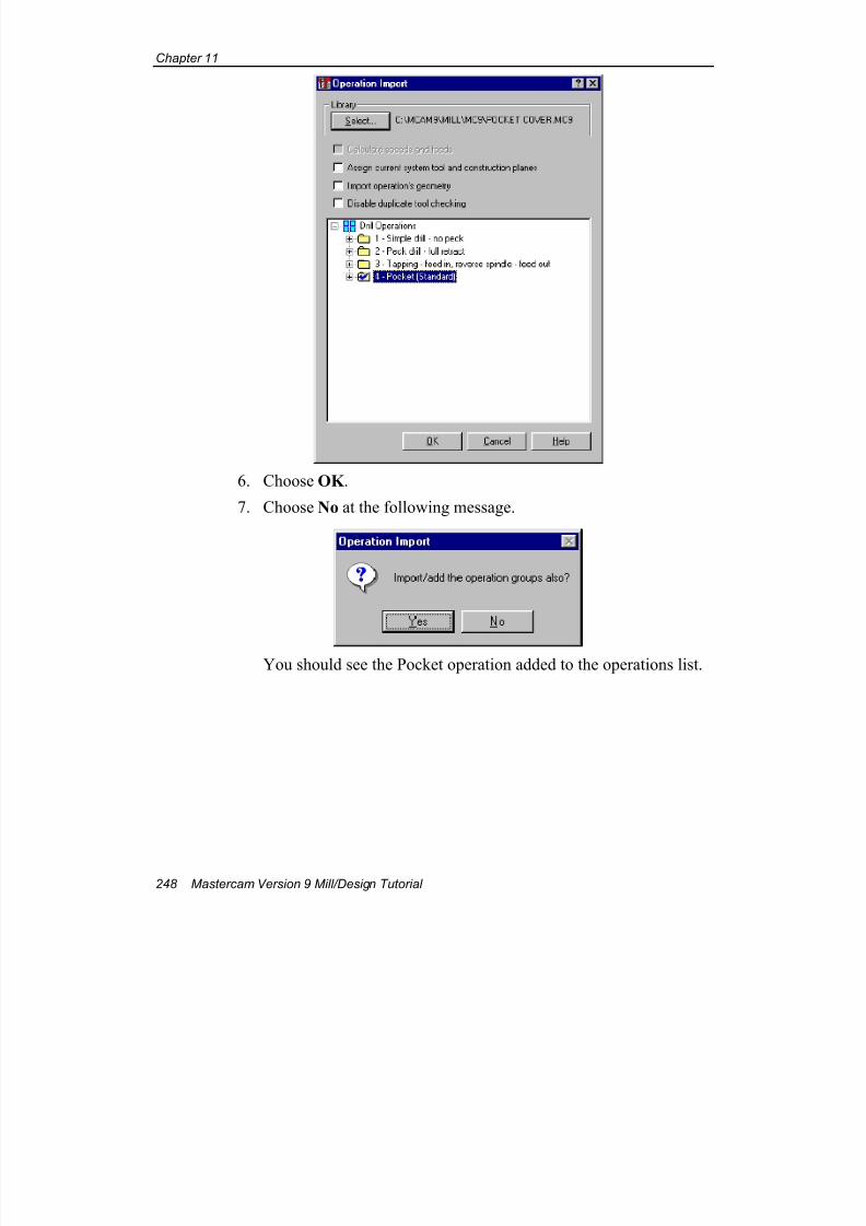
7/18/2019 V9 Mill-Design Tutorial (metric).pdf
http://slidepdf.com/reader/full/v9-mill-design-tutorial-metricpdf 260/453
Chapter 11
248 Mastercam Version 9 Mill/Design Tutorial
6. Choose OK .
7. Choose No at the following message.
You should see the Pocket operation added to the operations list.
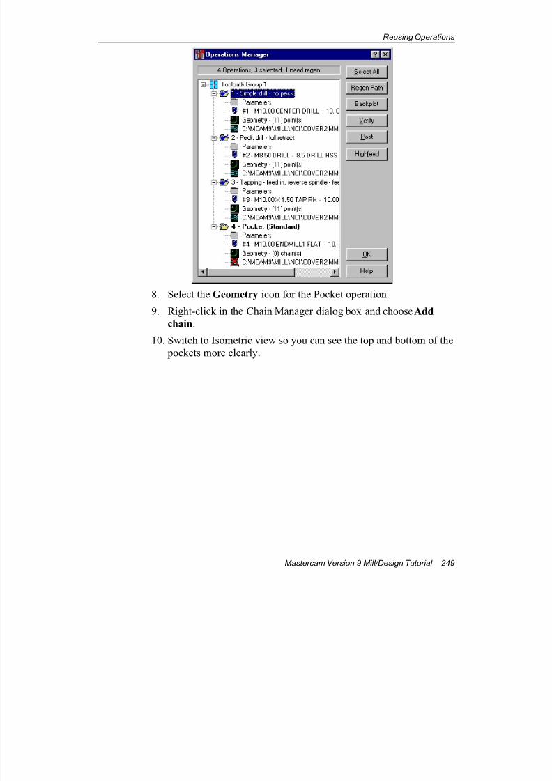
7/18/2019 V9 Mill-Design Tutorial (metric).pdf
http://slidepdf.com/reader/full/v9-mill-design-tutorial-metricpdf 261/453
Reusing Operations
Mastercam Version 9 Mill/Design Tutorial 249
8. Select the Geometry icon for the Pocket operation.
9. Right-click in the Chain Manager dialog box and choose Add
chain.
10. Switch to Isometric view so you can see the top and bottom of the
pockets more clearly.
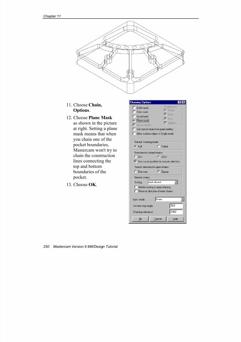
7/18/2019 V9 Mill-Design Tutorial (metric).pdf
http://slidepdf.com/reader/full/v9-mill-design-tutorial-metricpdf 262/453
Chapter 11
250 Mastercam Version 9 Mill/Design Tutorial
11. Choose Chain,
Options.
12. Choose Plane Mask as shown in the picture
at right. Setting a planemask means that when
you chain one of the
pocket boundaries,Mastercam won't try to
chain the construction
lines connecting the
top and bottom boundaries of the
pocket.
13. Choose OK .
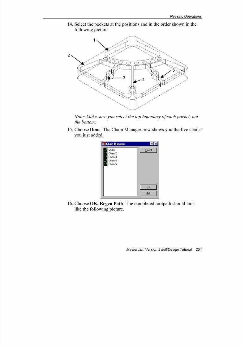
7/18/2019 V9 Mill-Design Tutorial (metric).pdf
http://slidepdf.com/reader/full/v9-mill-design-tutorial-metricpdf 263/453
Reusing Operations
Mastercam Version 9 Mill/Design Tutorial 251
14. Select the pockets at the positions and in the order shown in the
following picture.
Note: Make sure you select the top boundary of each pocket, not
the bottom.
15. Choose Done. The Chain Manager now shows you the five chainsyou just added.
16. Choose OK, Regen Path. The completed toolpath should look
like the following picture.
1
2
3 4
5
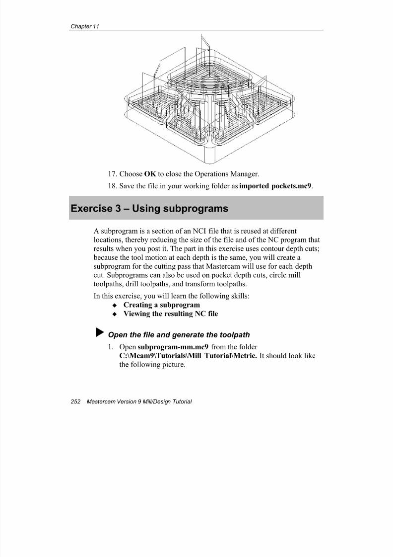
7/18/2019 V9 Mill-Design Tutorial (metric).pdf
http://slidepdf.com/reader/full/v9-mill-design-tutorial-metricpdf 264/453
Chapter 11
252 Mastercam Version 9 Mill/Design Tutorial
17. Choose OK to close the Operations Manager.
18. Save the file in your working folder as imported pockets.mc9.
Exercise 3 – Using subprograms
A subprogram is a section of an NCI file that is reused at differentlocations, thereby reducing the size of the file and of the NC program that
results when you post it. The part in this exercise uses contour depth cuts;
because the tool motion at each depth is the same, you will create a
subprogram for the cutting pass that Mastercam will use for each depthcut. Subprograms can also be used on pocket depth cuts, circle mill
toolpaths, drill toolpaths, and transform toolpaths.
In this exercise, you will learn the following skills:
Creating a subprogram
Viewing the resulting NC file
Open the file and generate the toolpath
1. Open subprogram-mm.mc9 from the folder
C:\Mcam9\Tutorials\Mill Tutorial\Metric. It should look likethe following picture.
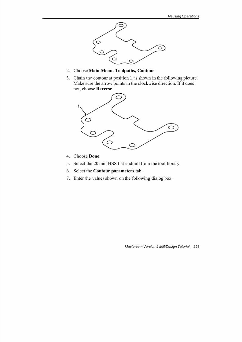
7/18/2019 V9 Mill-Design Tutorial (metric).pdf
http://slidepdf.com/reader/full/v9-mill-design-tutorial-metricpdf 265/453
Reusing Operations
Mastercam Version 9 Mill/Design Tutorial 253
2. Choose Main Menu, Toolpaths, Contour.
3. Chain the contour at position 1 as shown in the following picture.Make sure the arrow points in the clockwise direction. If it does
not, choose Reverse.
1
4. Choose Done.
5. Select the 20 mm HSS flat endmill from the tool library.
6. Select the Contour parameters tab.
7. Enter the values shown on the following dialog box.
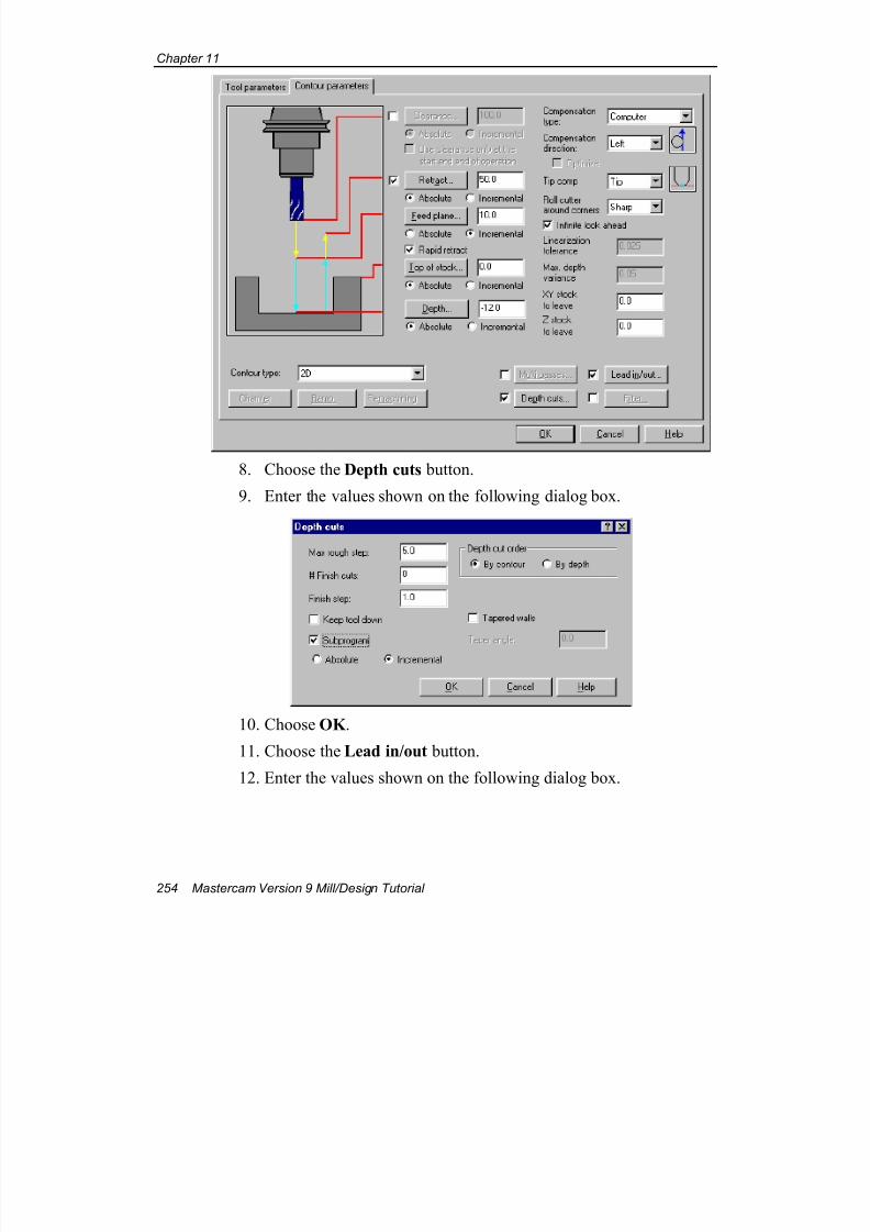
7/18/2019 V9 Mill-Design Tutorial (metric).pdf
http://slidepdf.com/reader/full/v9-mill-design-tutorial-metricpdf 266/453
Chapter 11
254 Mastercam Version 9 Mill/Design Tutorial
8. Choose the Depth cuts button.
9. Enter the values shown on the following dialog box.
10. Choose OK .
11. Choose the Lead in/out button.
12. Enter the values shown on the following dialog box.
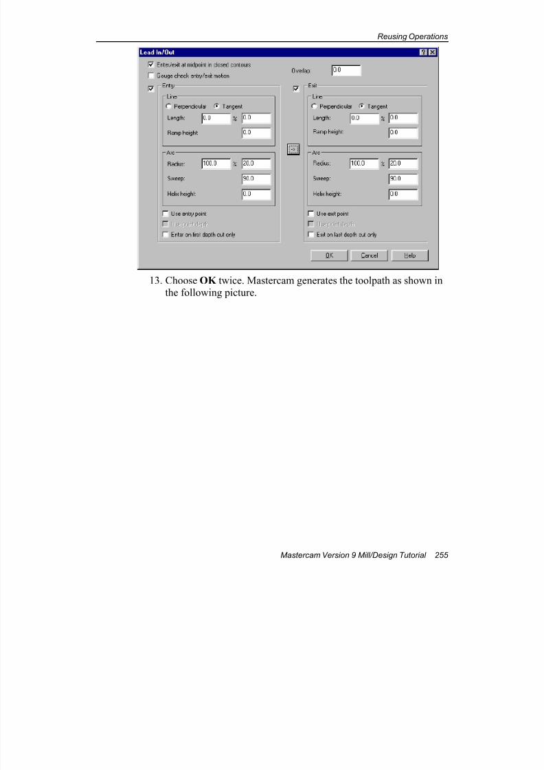
7/18/2019 V9 Mill-Design Tutorial (metric).pdf
http://slidepdf.com/reader/full/v9-mill-design-tutorial-metricpdf 267/453
Reusing Operations
Mastercam Version 9 Mill/Design Tutorial 255
13. Choose OK twice. Mastercam generates the toolpath as shown inthe following picture.
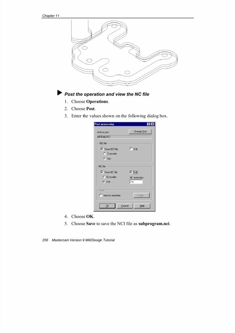
7/18/2019 V9 Mill-Design Tutorial (metric).pdf
http://slidepdf.com/reader/full/v9-mill-design-tutorial-metricpdf 268/453
Chapter 11
256 Mastercam Version 9 Mill/Design Tutorial
Post the operation and view the NC file
1. Choose Operations.
2. Choose Post.
3. Enter the values shown on the following dialog box.
4. Choose OK .
5. Choose Save to save the NCI file as subprogram.nci.

7/18/2019 V9 Mill-Design Tutorial (metric).pdf
http://slidepdf.com/reader/full/v9-mill-design-tutorial-metricpdf 269/453
Reusing Operations
Mastercam Version 9 Mill/Design Tutorial 257
6. Choose Save to save the NC file as subprogram.nc. Mastercam
displays the NC file in the default text editor. The NC file shouldlook like the following picture.
The subprogram code replaces many blocks that would otherwise be repeated, reducing the size of the NC file.
7. Close the text editor.
8. Choose OK to close the Operations Manager.
9. Save the file in your working folder as cut-depthsubprogram.mc9.
This chapter completes the section on wireframe geometry. The rest of this
tutorial introduces you to machining more sophisticated geometry such assurfaces and solids.
Tip: The M98 orM99 code is asubprogramindicator.

7/18/2019 V9 Mill-Design Tutorial (metric).pdf
http://slidepdf.com/reader/full/v9-mill-design-tutorial-metricpdf 270/453
Chapter 11
258 Mastercam Version 9 Mill/Design Tutorial
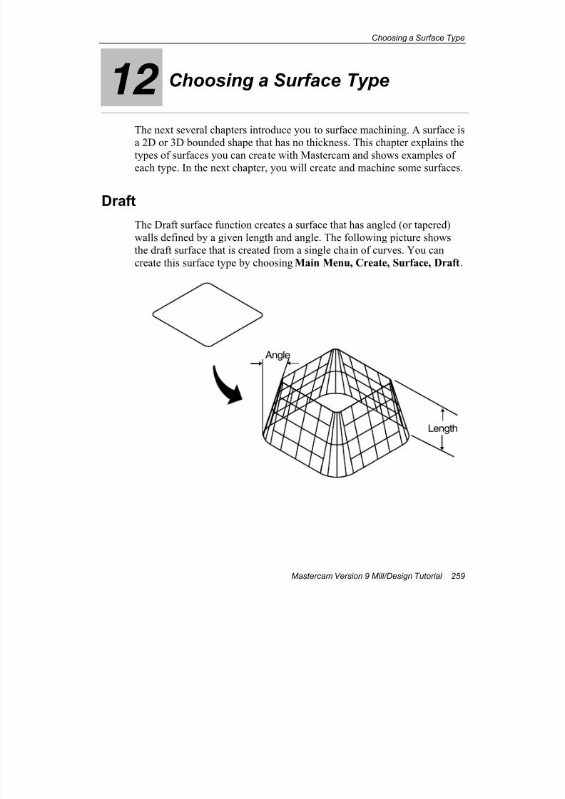
7/18/2019 V9 Mill-Design Tutorial (metric).pdf
http://slidepdf.com/reader/full/v9-mill-design-tutorial-metricpdf 271/453
Choosing a Surface Type
Mastercam Version 9 Mill/Design Tutorial 259
12 Choosing a Surface Type
The next several chapters introduce you to surface machining. A surface is
a 2D or 3D bounded shape that has no thickness. This chapter explains thetypes of surfaces you can create with Mastercam and shows examples ofeach type. In the next chapter, you will create and machine some surfaces.
Draft
The Draft surface function creates a surface that has angled (or tapered)
walls defined by a given length and angle. The following picture showsthe draft surface that is created from a single chain of curves. You can
create this surface type by choosing Main Menu, Create, Surface, Draft.
Angle
Length
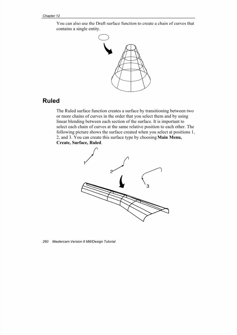
7/18/2019 V9 Mill-Design Tutorial (metric).pdf
http://slidepdf.com/reader/full/v9-mill-design-tutorial-metricpdf 272/453
Chapter 12
260 Mastercam Version 9 Mill/Design Tutorial
You can also use the Draft surface function to create a chain of curves thatcontains a single entity.
Ruled
The Ruled surface function creates a surface by transitioning between two
or more chains of curves in the order that you select them and by usinglinear blending between each section of the surface. It is important toselect each chain of curves at the same relative position to each other. The
following picture shows the surface created when you select at positions 1,
2, and 3. You can create this surface type by choosing Main Menu,
Create, Surface, Ruled.
1
2
3
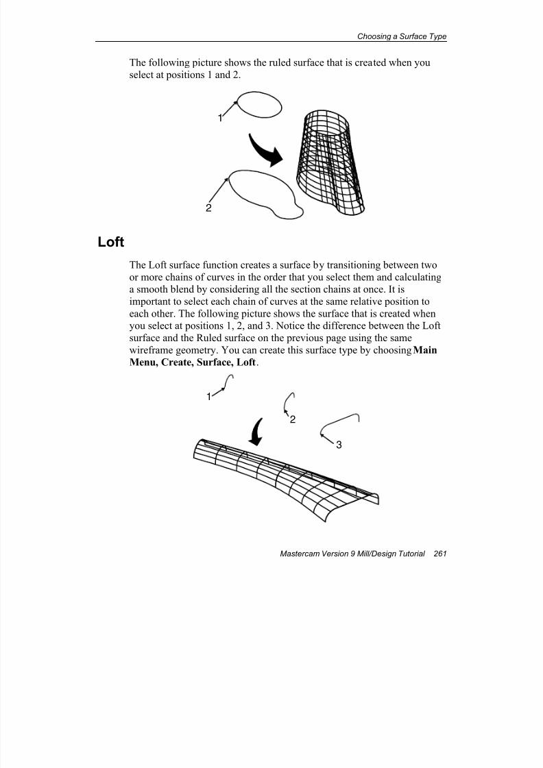
7/18/2019 V9 Mill-Design Tutorial (metric).pdf
http://slidepdf.com/reader/full/v9-mill-design-tutorial-metricpdf 273/453
Choosing a Surface Type
Mastercam Version 9 Mill/Design Tutorial 261
The following picture shows the ruled surface that is created when you
select at positions 1 and 2.
1
2
Loft
The Loft surface function creates a surface by transitioning between twoor more chains of curves in the order that you select them and calculatinga smooth blend by considering all the section chains at once. It is
important to select each chain of curves at the same relative position to
each other. The following picture shows the surface that is created whenyou select at positions 1, 2, and 3. Notice the difference between the Loft
surface and the Ruled surface on the previous page using the same
wireframe geometry. You can create this surface type by choosing Main
Menu, Create, Surface, Loft.
1
2
3
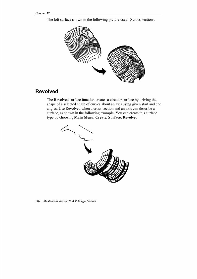
7/18/2019 V9 Mill-Design Tutorial (metric).pdf
http://slidepdf.com/reader/full/v9-mill-design-tutorial-metricpdf 274/453
Chapter 12
262 Mastercam Version 9 Mill/Design Tutorial
The loft surface shown in the following picture uses 40 cross-sections.
Revolved
The Revolved surface function creates a circular surface by driving theshape of a selected chain of curves about an axis using given start and end
angles. Use Revolved when a cross-section and an axis can describe a
surface, as shown in the following example. You can create this surfacetype by choosing Main Menu, Create, Surface, Revolve.
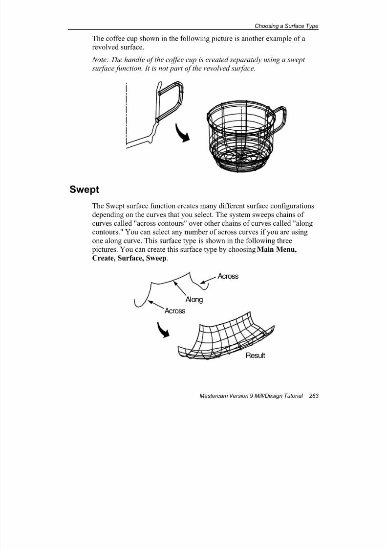
7/18/2019 V9 Mill-Design Tutorial (metric).pdf
http://slidepdf.com/reader/full/v9-mill-design-tutorial-metricpdf 275/453
Choosing a Surface Type
Mastercam Version 9 Mill/Design Tutorial 263
The coffee cup shown in the following picture is another example of arevolved surface.
Note: The handle of the coffee cup is created separately using a swept
surface function. It is not part of the revolved surface.
SweptThe Swept surface function creates many different surface configurations
depending on the curves that you select. The system sweeps chains of
curves called "across contours" over other chains of curves called "alongcontours." You can select any number of across curves if you are using
one along curve. This surface type is shown in the following three
pictures. You can create this surface type by choosing Main Menu,
Create, Surface, Sweep.
A c r o s s
A l o n g
A c r o s s
Result
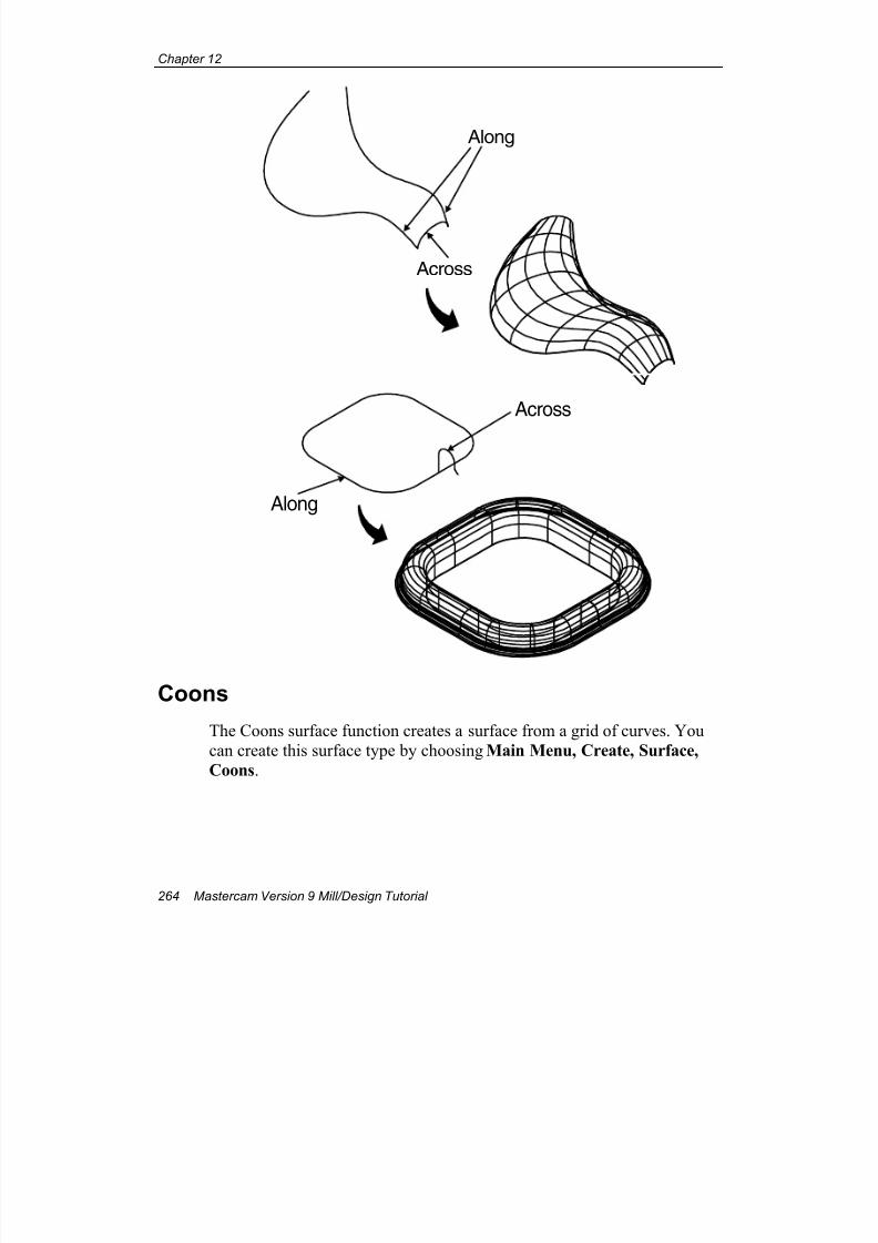
7/18/2019 V9 Mill-Design Tutorial (metric).pdf
http://slidepdf.com/reader/full/v9-mill-design-tutorial-metricpdf 276/453
Chapter 12
264 Mastercam Version 9 Mill/Design Tutorial
Along
Across
Across
Along
Coons
The Coons surface function creates a surface from a grid of curves. You
can create this surface type by choosing Main Menu, Create, Surface,
Coons.
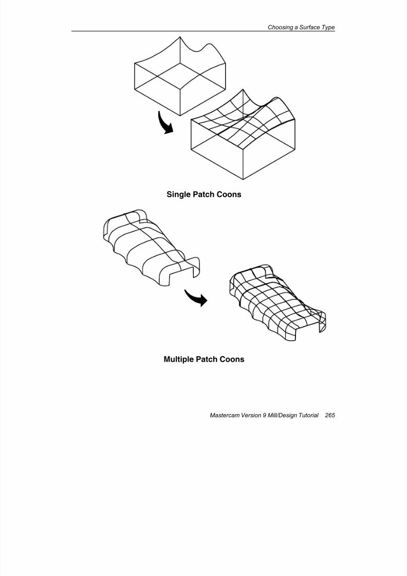
7/18/2019 V9 Mill-Design Tutorial (metric).pdf
http://slidepdf.com/reader/full/v9-mill-design-tutorial-metricpdf 277/453
Choosing a Surface Type
Mastercam Version 9 Mill/Design Tutorial 265
Single Patch Coons
Multiple Patch Coons
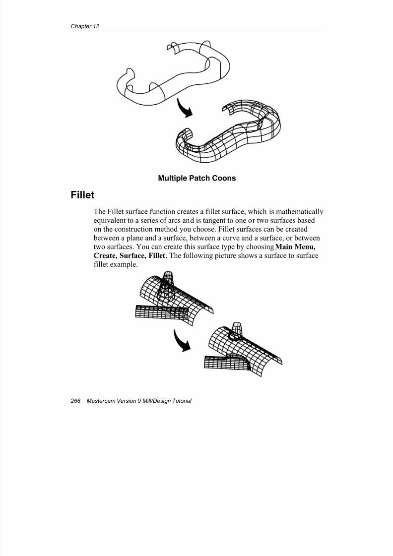
7/18/2019 V9 Mill-Design Tutorial (metric).pdf
http://slidepdf.com/reader/full/v9-mill-design-tutorial-metricpdf 278/453
Chapter 12
266 Mastercam Version 9 Mill/Design Tutorial
Multiple Patch Coons
FilletThe Fillet surface function creates a fillet surface, which is mathematically
equivalent to a series of arcs and is tangent to one or two surfaces basedon the construction method you choose. Fillet surfaces can be created
between a plane and a surface, between a curve and a surface, or betweentwo surfaces. You can create this surface type by choosing Main Menu,
Create, Surface, Fillet. The following picture shows a surface to surface
fillet example.
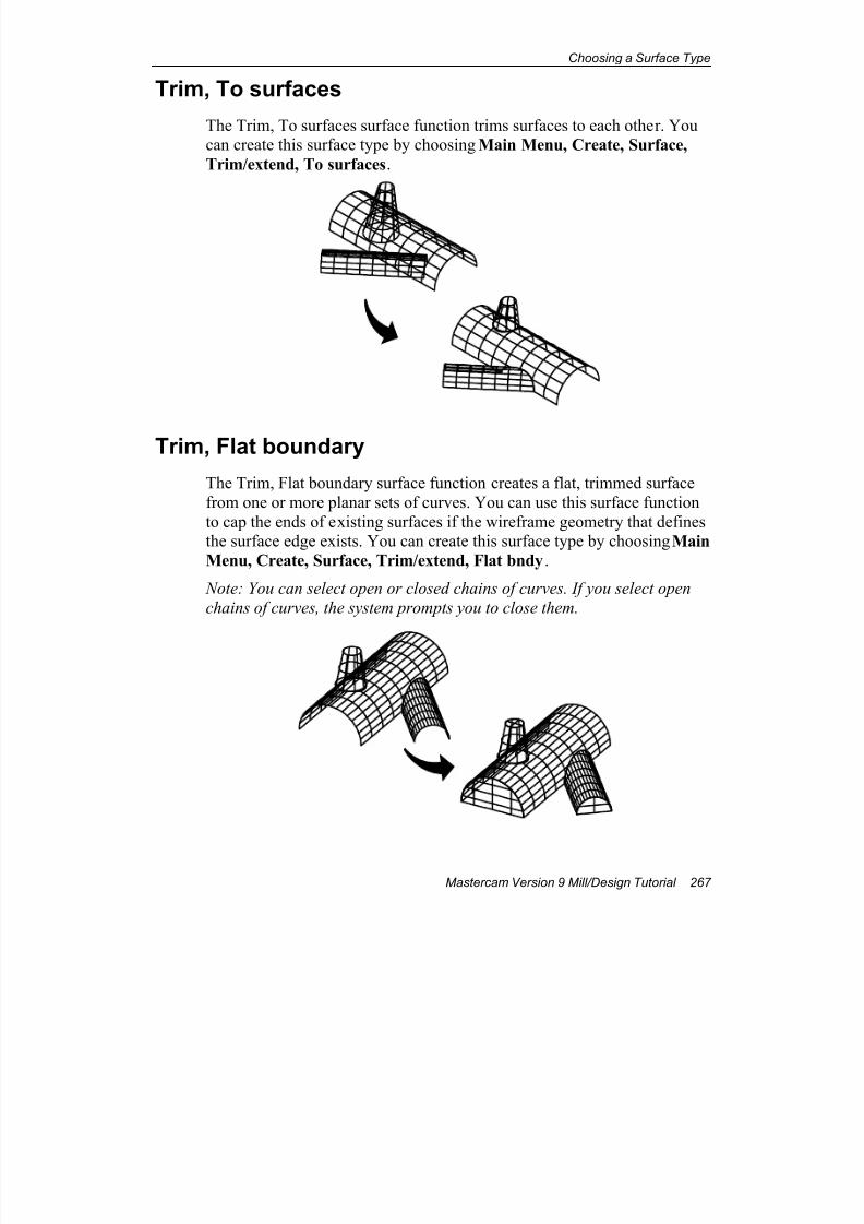
7/18/2019 V9 Mill-Design Tutorial (metric).pdf
http://slidepdf.com/reader/full/v9-mill-design-tutorial-metricpdf 279/453
Choosing a Surface Type
Mastercam Version 9 Mill/Design Tutorial 267
Trim, To surfaces
The Trim, To surfaces surface function trims surfaces to each other. Youcan create this surface type by choosing Main Menu, Create, Surface,
Trim/extend, To surfaces.
Trim, Flat boundary
The Trim, Flat boundary surface function creates a flat, trimmed surface
from one or more planar sets of curves. You can use this surface function
to cap the ends of existing surfaces if the wireframe geometry that definesthe surface edge exists. You can create this surface type by choosing Main
Menu, Create, Surface, Trim/extend, Flat bndy.
Note: You can select open or closed chains of curves. If you select open
chains of curves, the system prompts you to close them.
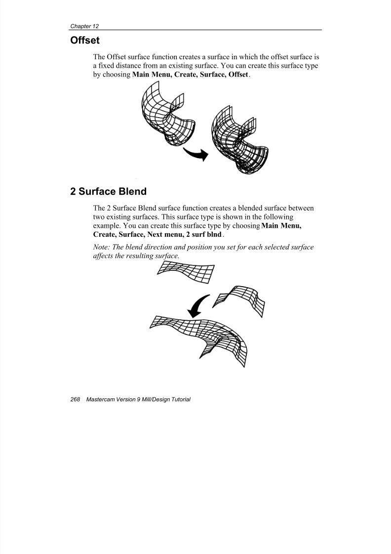
7/18/2019 V9 Mill-Design Tutorial (metric).pdf
http://slidepdf.com/reader/full/v9-mill-design-tutorial-metricpdf 280/453
Chapter 12
268 Mastercam Version 9 Mill/Design Tutorial
Offset
The Offset surface function creates a surface in which the offset surface isa fixed distance from an existing surface. You can create this surface type
by choosing Main Menu, Create, Surface, Offset.
2 Surface BlendThe 2 Surface Blend surface function creates a blended surface between
two existing surfaces. This surface type is shown in the following
example. You can create this surface type by choosing Main Menu,
Create, Surface, Next menu, 2 surf blnd.
Note: The blend direction and position you set for each selected surfaceaffects the resulting surface.
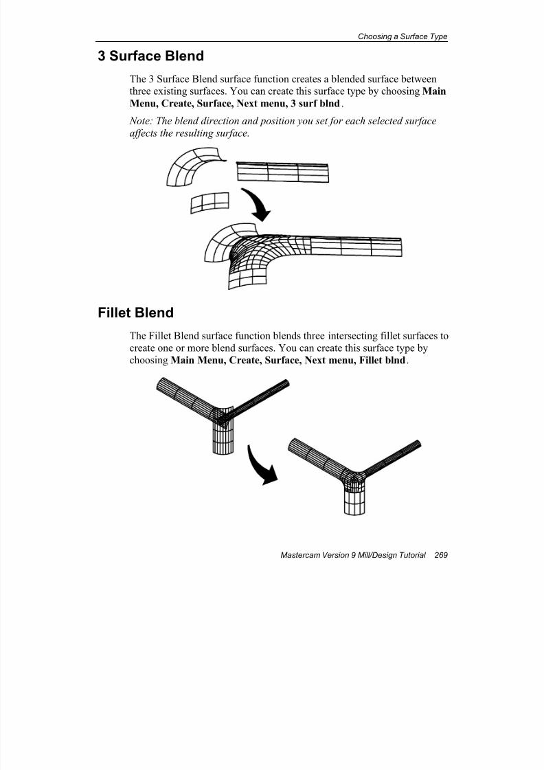
7/18/2019 V9 Mill-Design Tutorial (metric).pdf
http://slidepdf.com/reader/full/v9-mill-design-tutorial-metricpdf 281/453
Choosing a Surface Type
Mastercam Version 9 Mill/Design Tutorial 269
3 Surface Blend
The 3 Surface Blend surface function creates a blended surface betweenthree existing surfaces. You can create this surface type by choosing Main
Menu, Create, Surface, Next menu, 3 surf blnd.
Note: The blend direction and position you set for each selected surface
affects the resulting surface.
Fillet Blend
The Fillet Blend surface function blends three intersecting fillet surfaces to
create one or more blend surfaces. You can create this surface type bychoosing Main Menu, Create, Surface, Next menu, Fillet blnd.

7/18/2019 V9 Mill-Design Tutorial (metric).pdf
http://slidepdf.com/reader/full/v9-mill-design-tutorial-metricpdf 282/453
Chapter 12
270 Mastercam Version 9 Mill/Design Tutorial
Now that you've been introduced to different surface types and theirapplications, you're ready to create a part with surfaces and machine itwith surface toolpaths. The next chapter will show you how to do both.
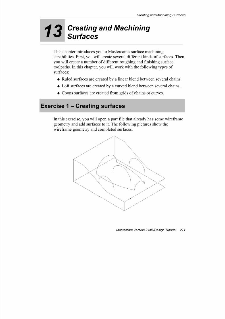
7/18/2019 V9 Mill-Design Tutorial (metric).pdf
http://slidepdf.com/reader/full/v9-mill-design-tutorial-metricpdf 283/453
Creating and Machining Surfaces
Mastercam Version 9 Mill/Design Tutorial 271
13 Creating and MachiningSurfaces
This chapter introduces you to Mastercam's surface machining
capabilities. First, you will create several different kinds of surfaces. Then,you will create a number of different roughing and finishing surface
toolpaths. In this chapter, you will work with the following types of
surfaces:
Ruled surfaces are created by a linear blend between several chains.
Loft surfaces are created by a curved blend between several chains.
Coons surfaces are created from grids of chains or curves.
Exercise 1 – Creating surfaces
In this exercise, you will open a part file that already has some wireframe
geometry and add surfaces to it. The following pictures show the
wireframe geometry and completed surfaces.
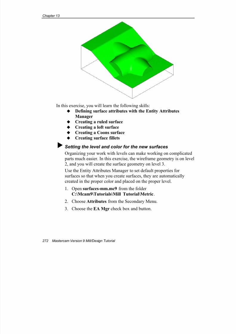
7/18/2019 V9 Mill-Design Tutorial (metric).pdf
http://slidepdf.com/reader/full/v9-mill-design-tutorial-metricpdf 284/453
Chapter 13
272 Mastercam Version 9 Mill/Design Tutorial
In this exercise, you will learn the following skills:
Defining surface attributes with the Entity Attributes
Manager Creating a ruled surface
Creating a loft surface
Creating a Coons surface
Creating surface fillets
Setting the level and color for the new surfaces
Organizing your work with levels can make working on complicated
parts much easier. In this exercise, the wireframe geometry is on level
2, and you will create the surface geometry on level 3.
Use the Entity Attributes Manager to set default properties for
surfaces so that when you create surfaces, they are automaticallycreated in the proper color and placed on the proper level.
1. Open surfaces-mm.mc9 from the folder
C:\Mcam9\Tutorials\Mill Tutorial\Metric.
2. Choose Attributes from the Secondary Menu.
3. Choose the EA Mgr check box and button.
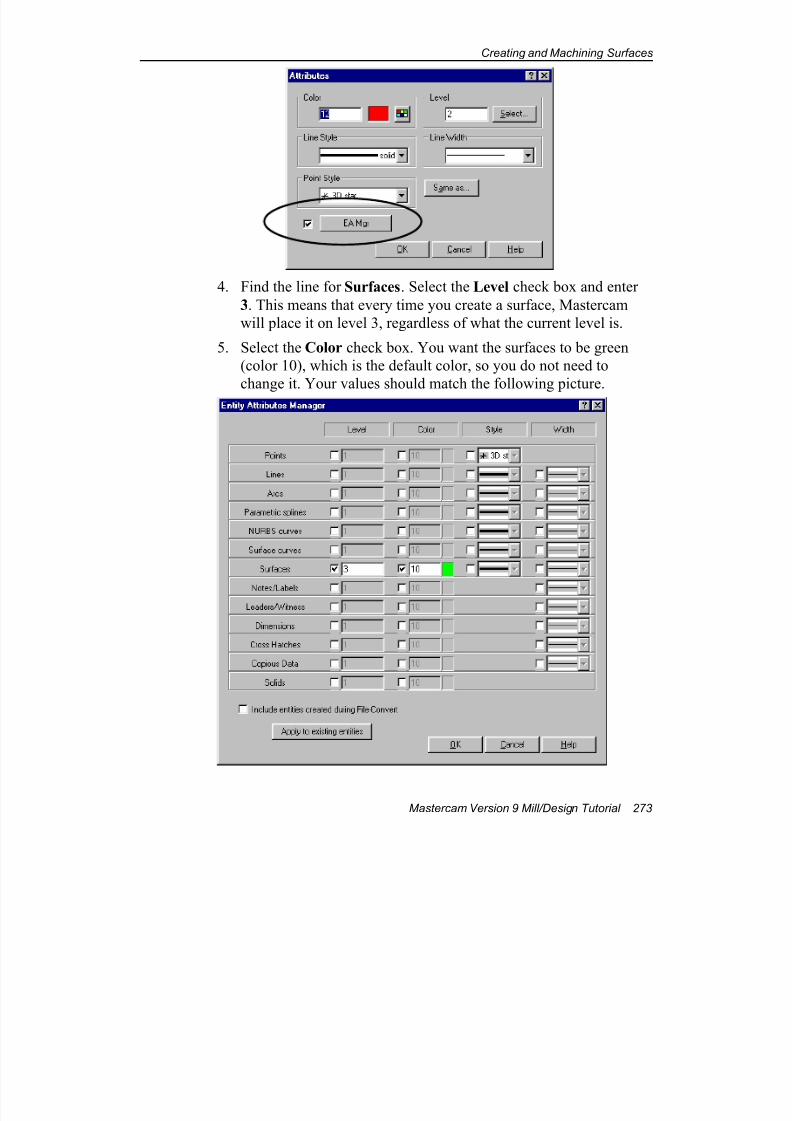
7/18/2019 V9 Mill-Design Tutorial (metric).pdf
http://slidepdf.com/reader/full/v9-mill-design-tutorial-metricpdf 285/453
Creating and Machining Surfaces
Mastercam Version 9 Mill/Design Tutorial 273
4. Find the line for Surfaces. Select the Level check box and enter
3. This means that every time you create a surface, Mastercam
will place it on level 3, regardless of what the current level is.
5. Select the Color check box. You want the surfaces to be green
(color 10), which is the default color, so you do not need to
change it. Your values should match the following picture.
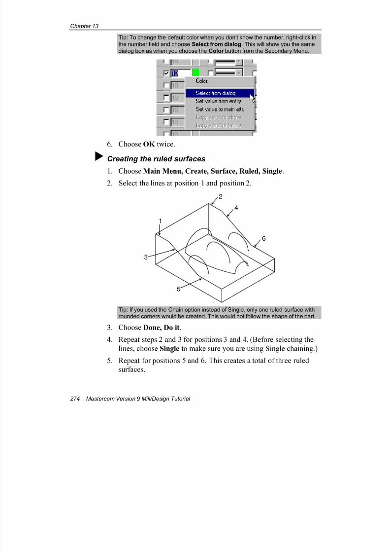
7/18/2019 V9 Mill-Design Tutorial (metric).pdf
http://slidepdf.com/reader/full/v9-mill-design-tutorial-metricpdf 286/453
Chapter 13
274 Mastercam Version 9 Mill/Design Tutorial
Tip: To change the default color when you don't know the number, right-click in
the number field and choose Select from dialog. This will show you the samedialog box as when you choose the Color button from the Secondary Menu.
6. Choose OK twice.
Creating the ruled surfaces
1. Choose Main Menu, Create, Surface, Ruled, Single.
2. Select the lines at position 1 and position 2.
1
2
3
4
5
6
Tip: If you used the Chain option instead of Single, only one ruled surface withrounded corners would be created. This would not follow the shape of the part.
3. Choose Done, Do it.
4. Repeat steps 2 and 3 for positions 3 and 4. (Before selecting the
lines, choose Single to make sure you are using Single chaining.)
5. Repeat for positions 5 and 6. This creates a total of three ruled
surfaces.
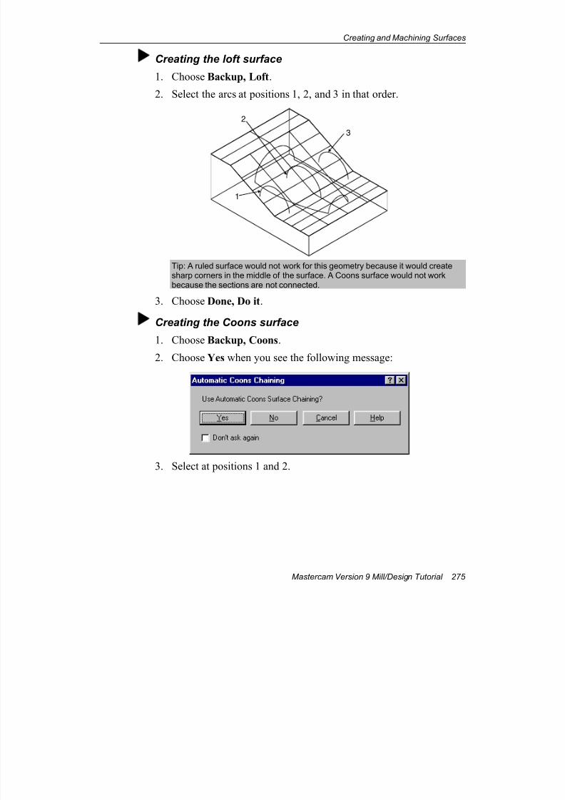
7/18/2019 V9 Mill-Design Tutorial (metric).pdf
http://slidepdf.com/reader/full/v9-mill-design-tutorial-metricpdf 287/453
Creating and Machining Surfaces
Mastercam Version 9 Mill/Design Tutorial 275
Creating the loft surface
1. Choose Backup, Loft.
2. Select the arcs at positions 1, 2, and 3 in that order.
1
3
2
Tip: A ruled surface would not work for this geometry because it would createsharp corners in the middle of the surface. A Coons surface would not workbecause the sections are not connected.
3. Choose Done, Do it.
Creating the Coons surface
1. Choose Backup, Coons.
2. Choose Yes when you see the following message:
3. Select at positions 1 and 2.
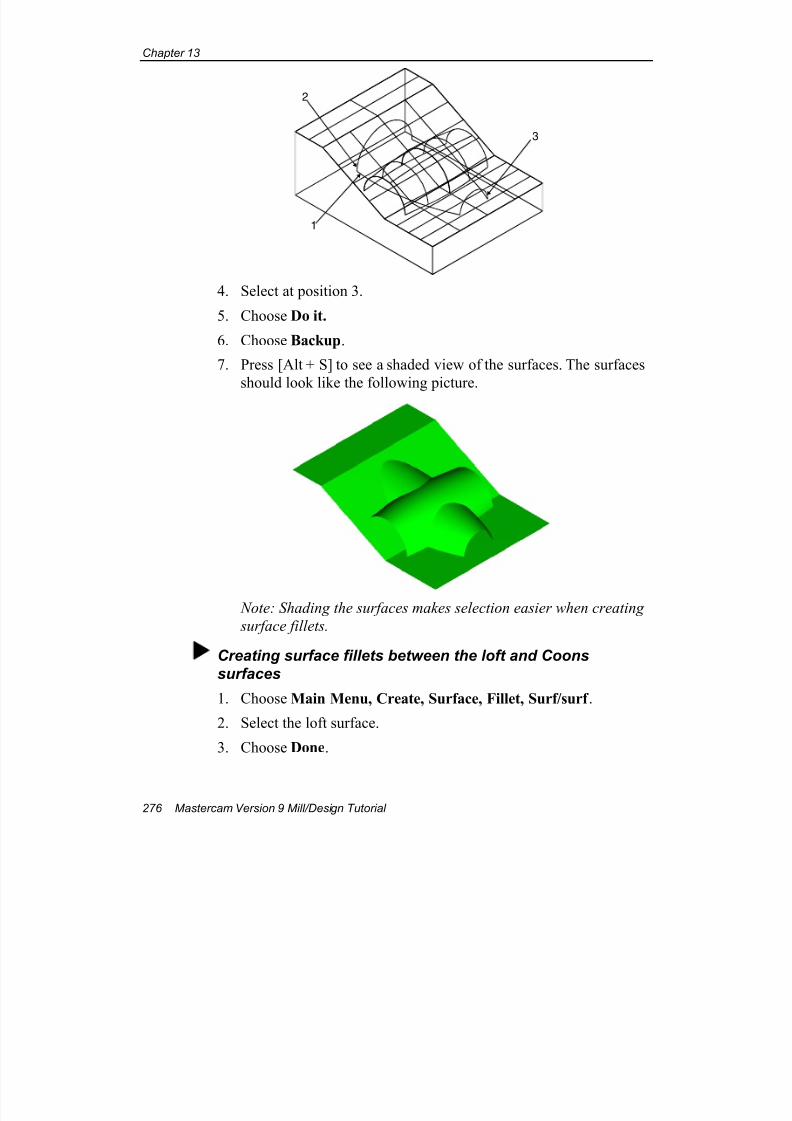
7/18/2019 V9 Mill-Design Tutorial (metric).pdf
http://slidepdf.com/reader/full/v9-mill-design-tutorial-metricpdf 288/453
Chapter 13
276 Mastercam Version 9 Mill/Design Tutorial
3
2
1
4. Select at position 3.
5. Choose Do it.
6. Choose Backup.
7. Press [Alt + S] to see a shaded view of the surfaces. The surfaces
should look like the following picture.
Note: Shading the surfaces makes selection easier when creating
surface fillets.
Creating surface fillets between the loft and Coons
surfaces
1. Choose Main Menu, Create, Surface, Fillet, Surf/surf .
2. Select the loft surface.
3. Choose Done.
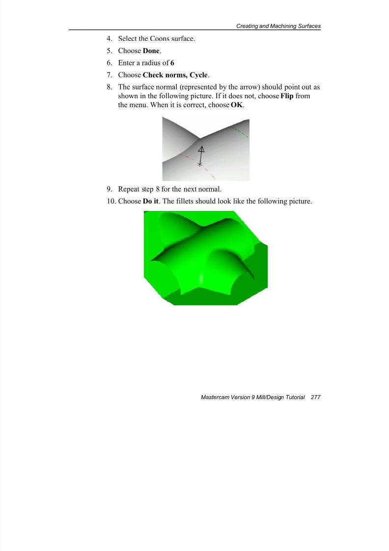
7/18/2019 V9 Mill-Design Tutorial (metric).pdf
http://slidepdf.com/reader/full/v9-mill-design-tutorial-metricpdf 289/453
Creating and Machining Surfaces
Mastercam Version 9 Mill/Design Tutorial 277
4. Select the Coons surface.
5. Choose Done.
6. Enter a radius of 6
7. Choose Check norms, Cycle.
8. The surface normal (represented by the arrow) should point out as
shown in the following picture. If it does not, choose Flip fromthe menu. When it is correct, choose OK .
9. Repeat step 8 for the next normal.
10. Choose Do it. The fillets should look like the following picture.
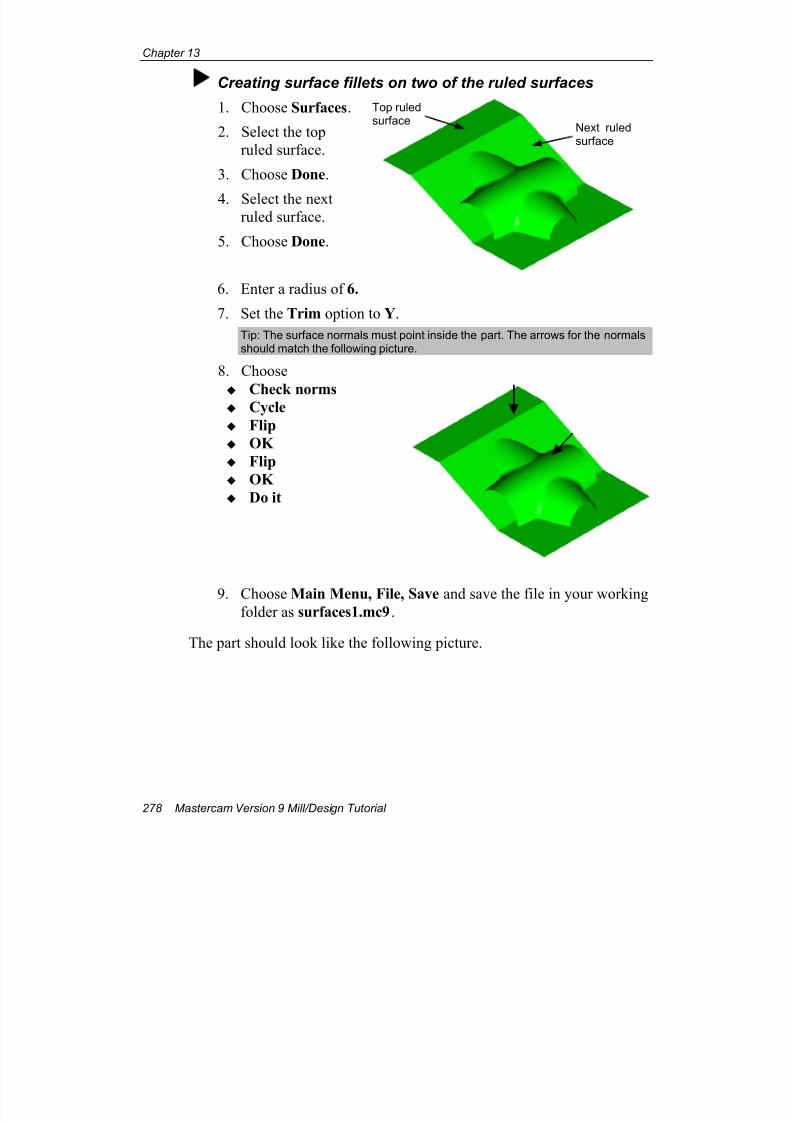
7/18/2019 V9 Mill-Design Tutorial (metric).pdf
http://slidepdf.com/reader/full/v9-mill-design-tutorial-metricpdf 290/453
Chapter 13
278 Mastercam Version 9 Mill/Design Tutorial
Creating surface fillets on two of the ruled surfaces
1. Choose Surfaces.
2. Select the top
ruled surface.
3. Choose Done.
4. Select the nextruled surface.
5. Choose Done.
6. Enter a radius of 6.
7. Set the Trim option to Y.
Tip: The surface normals must point inside the part. The arrows for the normalsshould match the following picture.
8. Choose
Check norms Cycle
Flip
OK
Flip
OK
Do it
9. Choose Main Menu, File, Save and save the file in your workingfolder as surfaces1.mc9.
The part should look like the following picture.
Top ruledsurface
Next ruledsurface
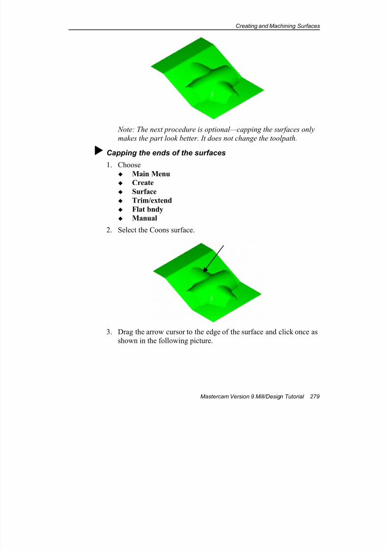
7/18/2019 V9 Mill-Design Tutorial (metric).pdf
http://slidepdf.com/reader/full/v9-mill-design-tutorial-metricpdf 291/453
Creating and Machining Surfaces
Mastercam Version 9 Mill/Design Tutorial 279
Note: The next procedure is optional—capping the surfaces only
makes the part look better. It does not change the toolpath.
Capping the ends of the surfaces
1. Choose
Main Menu
Create
Surface Trim/extend
Flat bndy
Manual
2. Select the Coons surface.
3. Drag the arrow cursor to the edge of the surface and click once as
shown in the following picture.
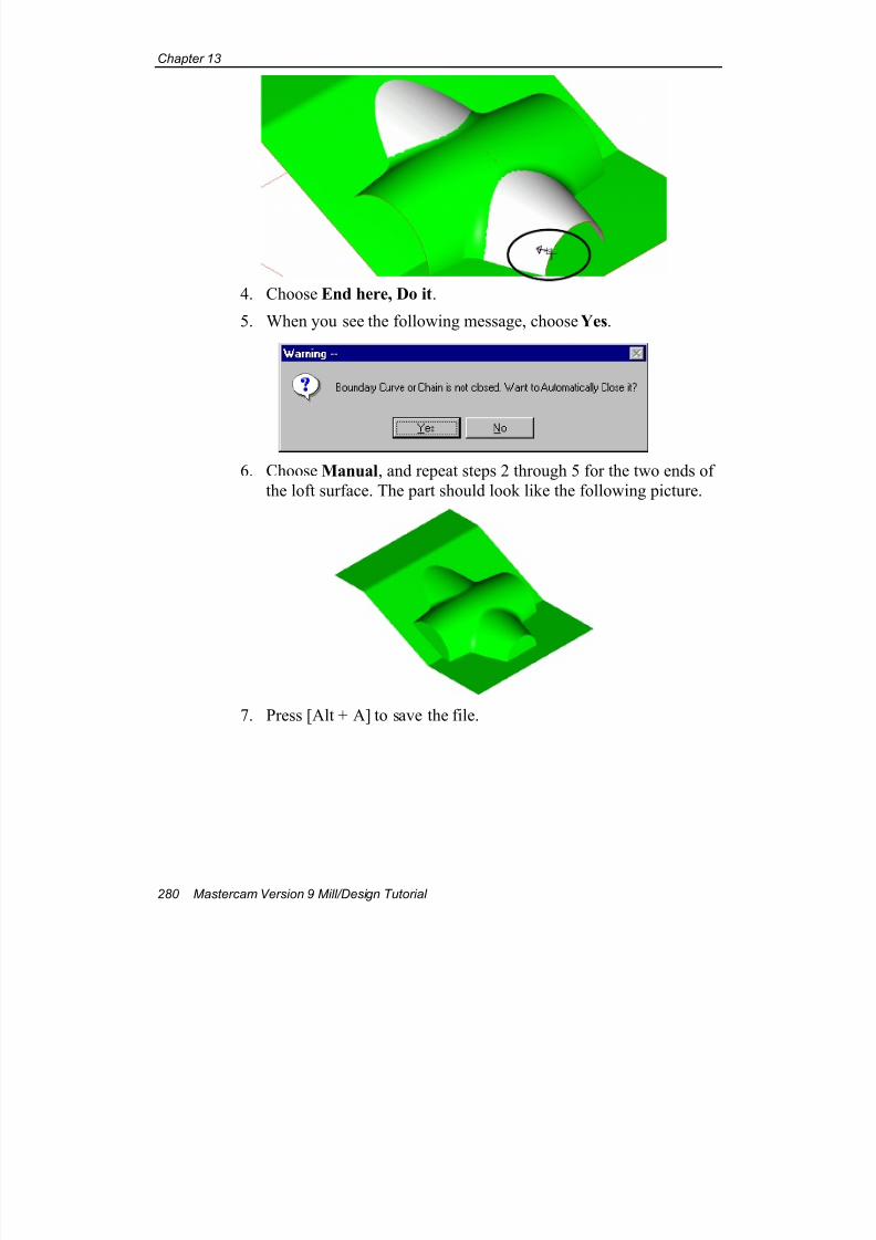
7/18/2019 V9 Mill-Design Tutorial (metric).pdf
http://slidepdf.com/reader/full/v9-mill-design-tutorial-metricpdf 292/453
Chapter 13
280 Mastercam Version 9 Mill/Design Tutorial
4. Choose End here, Do it.
5. When you see the following message, choose Yes.
6. Choose Manual, and repeat steps 2 through 5 for the two ends of
the loft surface. The part should look like the following picture.
7. Press [Alt + A] to save the file.
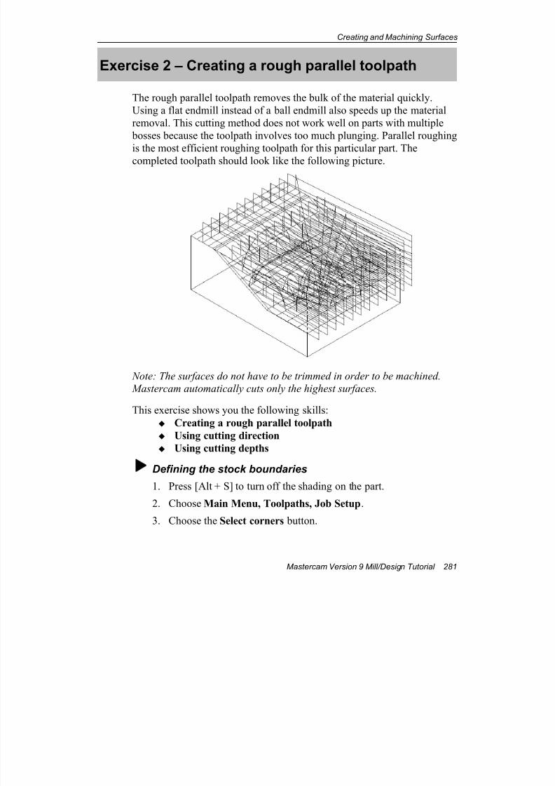
7/18/2019 V9 Mill-Design Tutorial (metric).pdf
http://slidepdf.com/reader/full/v9-mill-design-tutorial-metricpdf 293/453
Creating and Machining Surfaces
Mastercam Version 9 Mill/Design Tutorial 281
Exercise 2 – Creating a rough parallel toolpath
The rough parallel toolpath removes the bulk of the material quickly.
Using a flat endmill instead of a ball endmill also speeds up the material
removal. This cutting method does not work well on parts with multiple
bosses because the toolpath involves too much plunging. Parallel roughingis the most efficient roughing toolpath for this particular part. The
completed toolpath should look like the following picture.
Note: The surfaces do not have to be trimmed in order to be machined.
Mastercam automatically cuts only the highest surfaces.
This exercise shows you the following skills: Creating a rough parallel toolpath
Using cutting direction
Using cutting depths
Defining the stock boundaries
1. Press [Alt + S] to turn off the shading on the part.
2. Choose Main Menu, Toolpaths, Job Setup.
3. Choose the Select corners button.
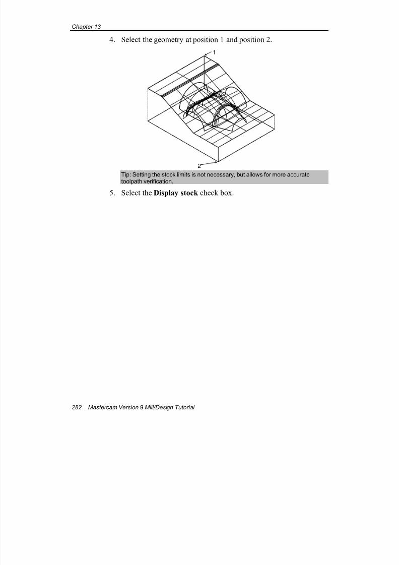
7/18/2019 V9 Mill-Design Tutorial (metric).pdf
http://slidepdf.com/reader/full/v9-mill-design-tutorial-metricpdf 294/453
Chapter 13
282 Mastercam Version 9 Mill/Design Tutorial
4. Select the geometry at position 1 and position 2.
1
2 Tip: Setting the stock limits is not necessary, but allows for more accuratetoolpath verification.
5. Select the Display stock check box.
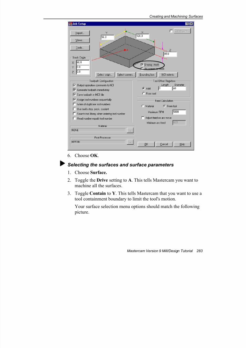
7/18/2019 V9 Mill-Design Tutorial (metric).pdf
http://slidepdf.com/reader/full/v9-mill-design-tutorial-metricpdf 295/453
Creating and Machining Surfaces
Mastercam Version 9 Mill/Design Tutorial 283
6. Choose OK .
Selecting the surfaces and surface parameters
1. Choose Surface.
2. Toggle the Drive setting to A. This tells Mastercam you want to
machine all the surfaces.
3. Toggle Contain to Y. This tells Mastercam that you want to use a
tool containment boundary to limit the tool's motion.
Your surface selection menu options should match the following
picture.
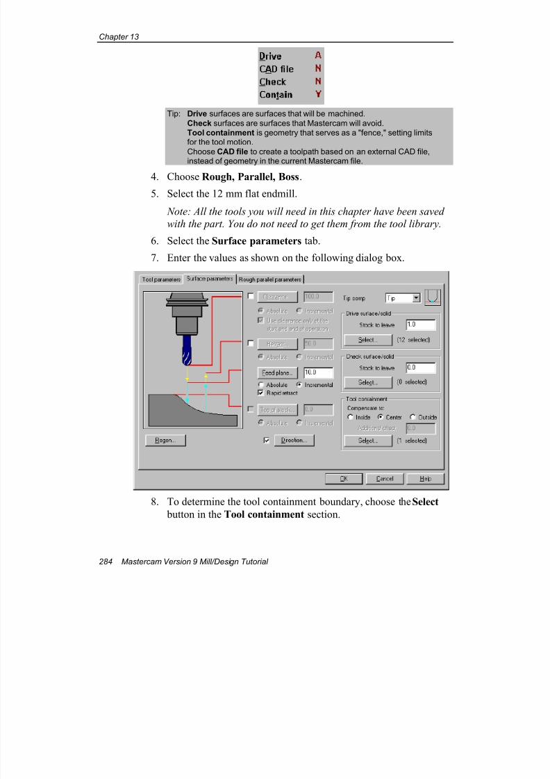
7/18/2019 V9 Mill-Design Tutorial (metric).pdf
http://slidepdf.com/reader/full/v9-mill-design-tutorial-metricpdf 296/453
Chapter 13
284 Mastercam Version 9 Mill/Design Tutorial
Tip: Drive surfaces are surfaces that will be machined.
Check surfaces are surfaces that Mastercam will avoid.
Tool containment is geometry that serves as a "fence," setting limitsfor the tool motion.
Choose CAD file to create a toolpath based on an external CAD file,instead of geometry in the current Mastercam file.
4. Choose Rough, Parallel, Boss.
5. Select the 12 mm flat endmill.
Note: All the tools you will need in this chapter have been saved
with the part. You do not need to get them from the tool library.
6. Select the Surface parameters tab.
7. Enter the values as shown on the following dialog box.
8. To determine the tool containment boundary, choose the Select
button in the Tool containment section.
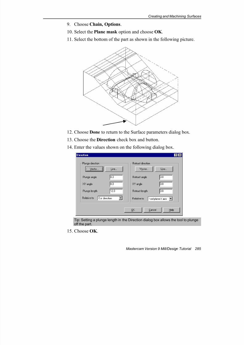
7/18/2019 V9 Mill-Design Tutorial (metric).pdf
http://slidepdf.com/reader/full/v9-mill-design-tutorial-metricpdf 297/453
Creating and Machining Surfaces
Mastercam Version 9 Mill/Design Tutorial 285
9. Choose Chain, Options.
10. Select the Plane mask option and choose OK .
11. Select the bottom of the part as shown in the following picture.
12. Choose Done to return to the Surface parameters dialog box.
13. Choose the Direction check box and button.
14. Enter the values shown on the following dialog box.
Tip: Setting a plunge length in the Direction dialog box allows the tool to plungeoff the part.
15. Choose OK .
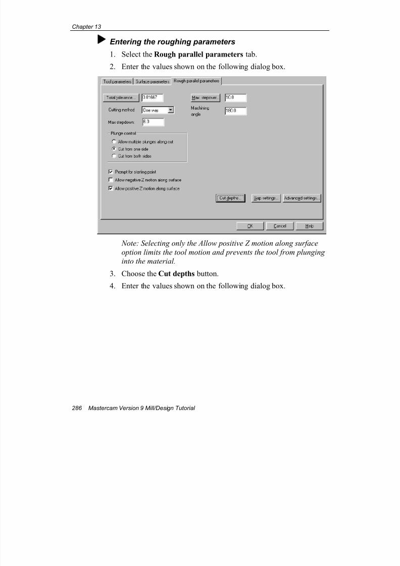
7/18/2019 V9 Mill-Design Tutorial (metric).pdf
http://slidepdf.com/reader/full/v9-mill-design-tutorial-metricpdf 298/453
Chapter 13
286 Mastercam Version 9 Mill/Design Tutorial
Entering the roughing parameters
1. Select the Rough parallel parameters tab.
2. Enter the values shown on the following dialog box.
Note: Selecting only the Allow positive Z motion along surface
option limits the tool motion and prevents the tool from plunging
into the material.
3. Choose the Cut depths button.
4. Enter the values shown on the following dialog box.
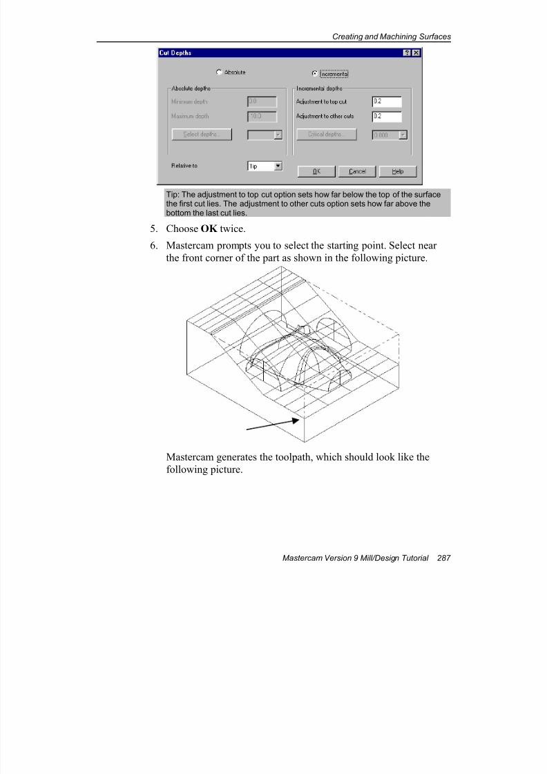
7/18/2019 V9 Mill-Design Tutorial (metric).pdf
http://slidepdf.com/reader/full/v9-mill-design-tutorial-metricpdf 299/453
Creating and Machining Surfaces
Mastercam Version 9 Mill/Design Tutorial 287
Tip: The adjustment to top cut option sets how far below the top of the surfacethe first cut lies. The adjustment to other cuts option sets how far above thebottom the last cut lies.
5. Choose OK twice.
6. Mastercam prompts you to select the starting point. Select near
the front corner of the part as shown in the following picture.
Mastercam generates the toolpath, which should look like the
following picture.
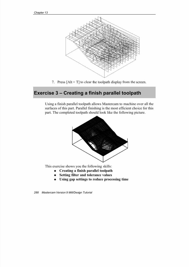
7/18/2019 V9 Mill-Design Tutorial (metric).pdf
http://slidepdf.com/reader/full/v9-mill-design-tutorial-metricpdf 300/453
Chapter 13
288 Mastercam Version 9 Mill/Design Tutorial
7. Press [Alt + T] to clear the toolpath display from the screen.
Exercise 3 – Creating a finish parallel toolpath
Using a finish parallel toolpath allows Mastercam to machine over all the
surfaces of this part. Parallel finishing is the most efficient choice for this
part. The completed toolpath should look like the following picture.
This exercise shows you the following skills:
Creating a finish parallel toolpath
Setting filter and tolerance values
Using gap settings to reduce processing time
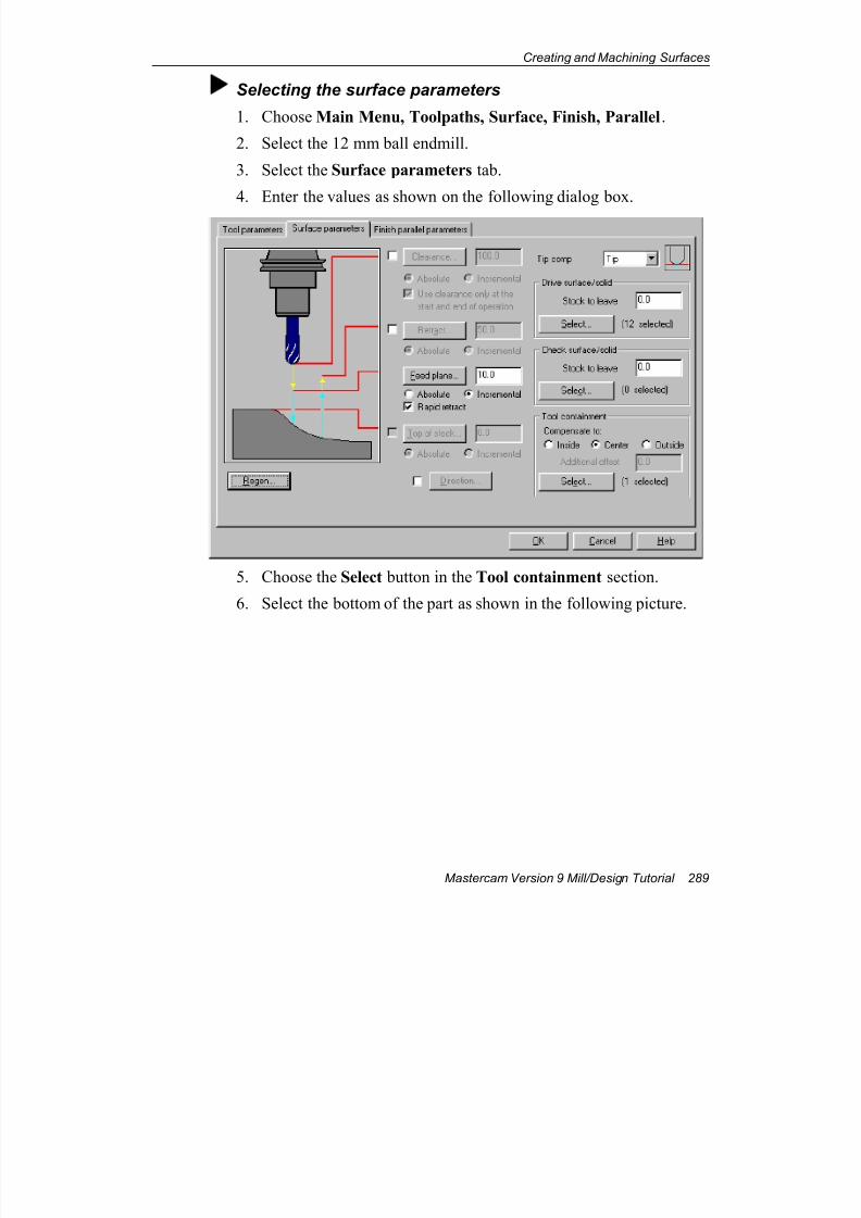
7/18/2019 V9 Mill-Design Tutorial (metric).pdf
http://slidepdf.com/reader/full/v9-mill-design-tutorial-metricpdf 301/453
Creating and Machining Surfaces
Mastercam Version 9 Mill/Design Tutorial 289
Selecting the surface parameters
1. Choose Main Menu, Toolpaths, Surface, Finish, Parallel.
2. Select the 12 mm ball endmill.
3. Select the Surface parameters tab.
4. Enter the values as shown on the following dialog box.
5. Choose the Select button in the Tool containment section.
6. Select the bottom of the part as shown in the following picture.
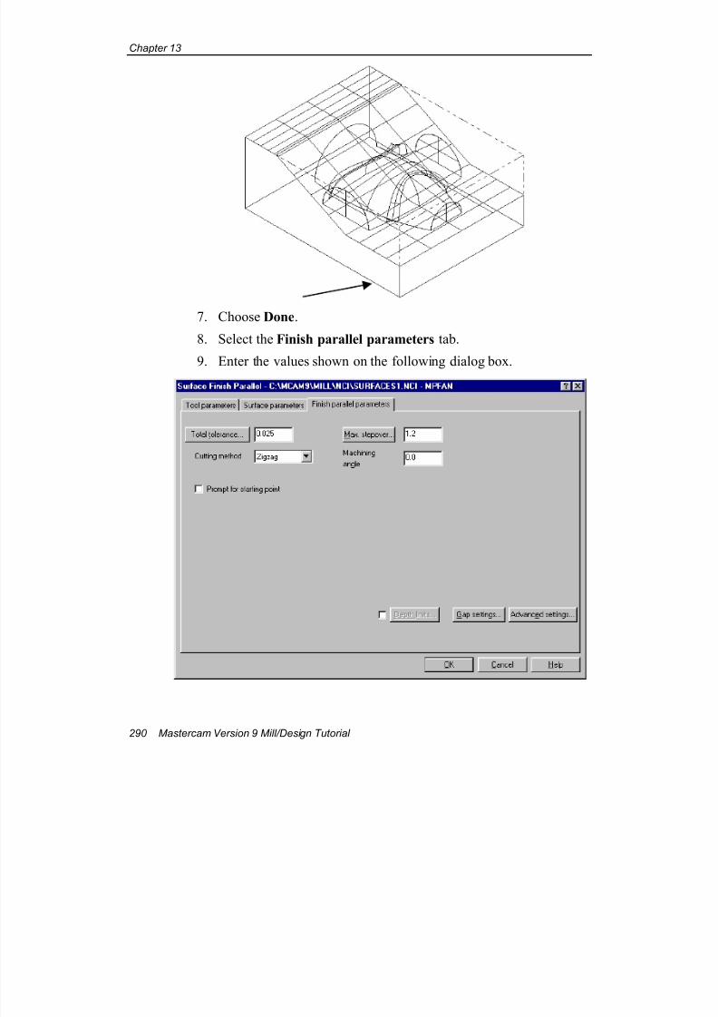
7/18/2019 V9 Mill-Design Tutorial (metric).pdf
http://slidepdf.com/reader/full/v9-mill-design-tutorial-metricpdf 302/453
Chapter 13
290 Mastercam Version 9 Mill/Design Tutorial
7. Choose Done.
8. Select the Finish parallel parameters tab.
9. Enter the values shown on the following dialog box.
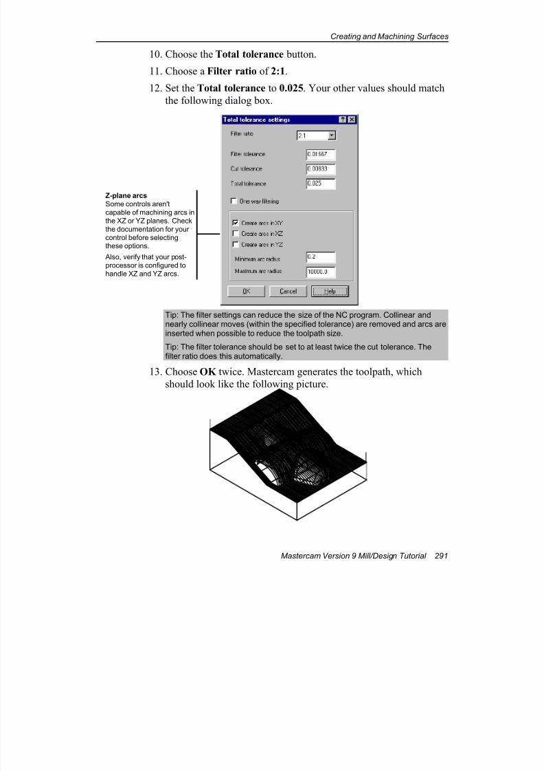
7/18/2019 V9 Mill-Design Tutorial (metric).pdf
http://slidepdf.com/reader/full/v9-mill-design-tutorial-metricpdf 303/453
Creating and Machining Surfaces
Mastercam Version 9 Mill/Design Tutorial 291
10. Choose the Total tolerance button.
11. Choose a Filter ratio of 2:1.
12. Set the Total tolerance to 0.025. Your other values should match
the following dialog box.
Tip: The filter settings can reduce the size of the NC program. Collinear andnearly collinear moves (within the specified tolerance) are removed and arcs areinserted when possible to reduce the toolpath size.
Tip: The filter tolerance should be set to at least twice the cut tolerance. Thefilter ratio does this automatically.
13. Choose OK twice. Mastercam generates the toolpath, which
should look like the following picture.
Z-plane arcs
Some controls aren't
capable of machining arcs in
the XZ or YZ planes. Check
the documentation for your
control before selectingthese options.
Also, verify that your post-
processor is configured to
handle XZ and YZ arcs.
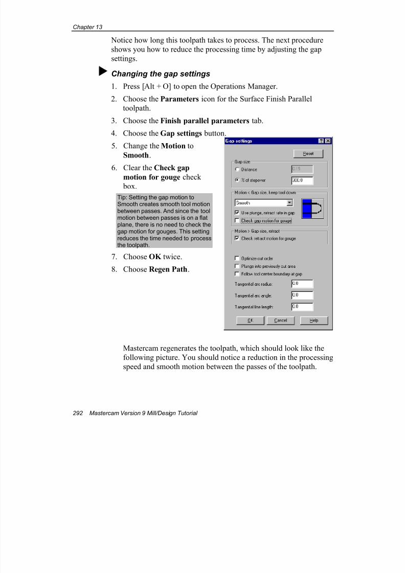
7/18/2019 V9 Mill-Design Tutorial (metric).pdf
http://slidepdf.com/reader/full/v9-mill-design-tutorial-metricpdf 304/453
Chapter 13
292 Mastercam Version 9 Mill/Design Tutorial
Notice how long this toolpath takes to process. The next procedure
shows you how to reduce the processing time by adjusting the gap
settings.
Changing the gap settings
1. Press [Alt + O] to open the Operations Manager.
2. Choose the Parameters icon for the Surface Finish Paralleltoolpath.
3. Choose the Finish parallel parameters tab.
4. Choose the Gap settings button.
5. Change the Motion to
Smooth.
6. Clear the Check gap
motion for gouge check
box.
Tip: Setting the gap motion toSmooth creates smooth tool motionbetween passes. And since the toolmotion between passes is on a flatplane, there is no need to check thegap motion for gouges. This settingreduces the time needed to processthe toolpath.
7. Choose OK twice.
8. Choose Regen Path.
Mastercam regenerates the toolpath, which should look like the
following picture. You should notice a reduction in the processing
speed and smooth motion between the passes of the toolpath.
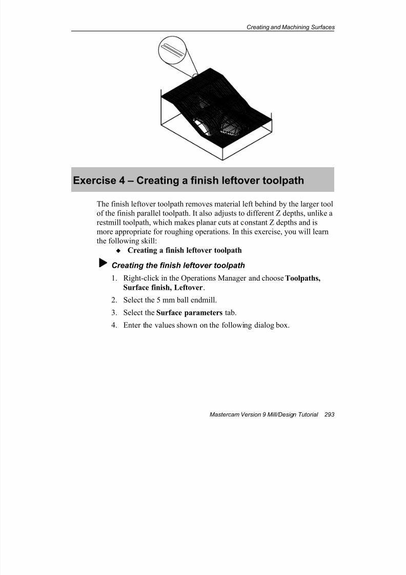
7/18/2019 V9 Mill-Design Tutorial (metric).pdf
http://slidepdf.com/reader/full/v9-mill-design-tutorial-metricpdf 305/453
Creating and Machining Surfaces
Mastercam Version 9 Mill/Design Tutorial 293
Exercise 4 – Creating a finish leftover toolpath
The finish leftover toolpath removes material left behind by the larger toolof the finish parallel toolpath. It also adjusts to different Z depths, unlike a
restmill toolpath, which makes planar cuts at constant Z depths and is
more appropriate for roughing operations. In this exercise, you will learn
the following skill:
Creating a finish leftover toolpath
Creating the finish leftover toolpath
1. Right-click in the Operations Manager and choose Toolpaths,
Surface finish, Leftover.
2. Select the 5 mm ball endmill.3. Select the Surface parameters tab.
4. Enter the values shown on the following dialog box.
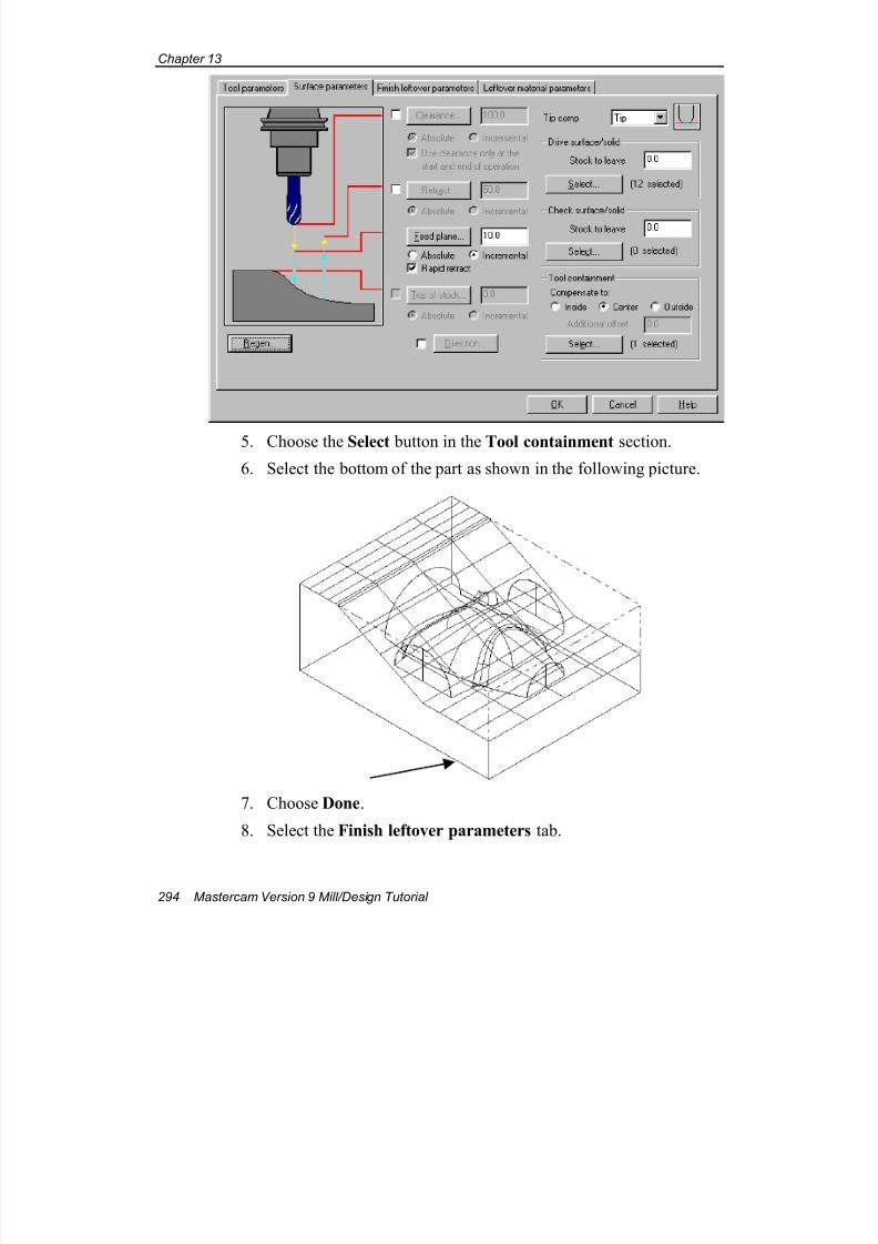
7/18/2019 V9 Mill-Design Tutorial (metric).pdf
http://slidepdf.com/reader/full/v9-mill-design-tutorial-metricpdf 306/453
Chapter 13
294 Mastercam Version 9 Mill/Design Tutorial
5. Choose the Select button in the Tool containment section.
6. Select the bottom of the part as shown in the following picture.
7. Choose Done.
8. Select the Finish leftover parameters tab.
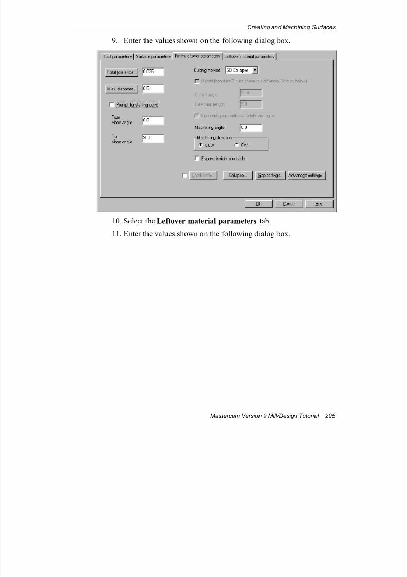
7/18/2019 V9 Mill-Design Tutorial (metric).pdf
http://slidepdf.com/reader/full/v9-mill-design-tutorial-metricpdf 307/453
Creating and Machining Surfaces
Mastercam Version 9 Mill/Design Tutorial 295
9. Enter the values shown on the following dialog box.
10. Select the Leftover material parameters tab.
11. Enter the values shown on the following dialog box.
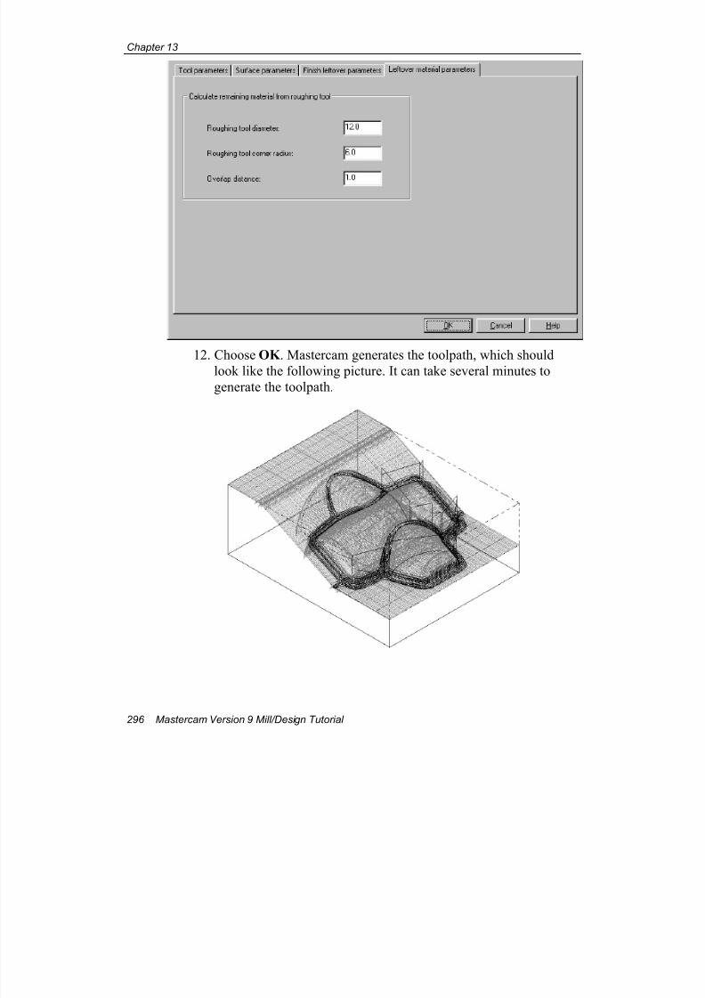
7/18/2019 V9 Mill-Design Tutorial (metric).pdf
http://slidepdf.com/reader/full/v9-mill-design-tutorial-metricpdf 308/453
Chapter 13
296 Mastercam Version 9 Mill/Design Tutorial
12. Choose OK . Mastercam generates the toolpath, which should
look like the following picture. It can take several minutes to
generate the toolpath.

7/18/2019 V9 Mill-Design Tutorial (metric).pdf
http://slidepdf.com/reader/full/v9-mill-design-tutorial-metricpdf 309/453
Creating and Machining Surfaces
Mastercam Version 9 Mill/Design Tutorial 297
Note: If you receive an error message stating that the toolpath
allocation is too low, choose Main Menu, Screen, Configure and
select the Allocations tab. Increase the value for the Toolpath
allocation in Kbytes option and choose OK . Finally, regenerate
the operation. This increases the amount of RAM designated for
toolpath functions.
Exercise 5 – Creating a finish pencil toolpath
On this geometry, the finish pencil toolpath cleans up more of the material
by driving the cutter tangent to two surfaces at a time. This exercise shows
you the following skills:
Creating a finish pencil toolpath
Verifying the toolpath
Creating the finish pencil toolpath
1. Right-click in the Operations Manager and choose Toolpaths,Surface finish, Pencil.
2. Select the 2 mm ball endmill.
3. Select the Surface parameters tab.
4. Enter the values shown on the following dialog box.
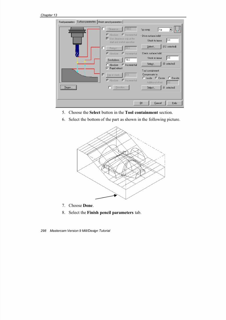
7/18/2019 V9 Mill-Design Tutorial (metric).pdf
http://slidepdf.com/reader/full/v9-mill-design-tutorial-metricpdf 310/453
Chapter 13
298 Mastercam Version 9 Mill/Design Tutorial
5. Choose the Select button in the Tool containment section.
6. Select the bottom of the part as shown in the following picture.
7. Choose Done.
8. Select the Finish pencil parameters tab.
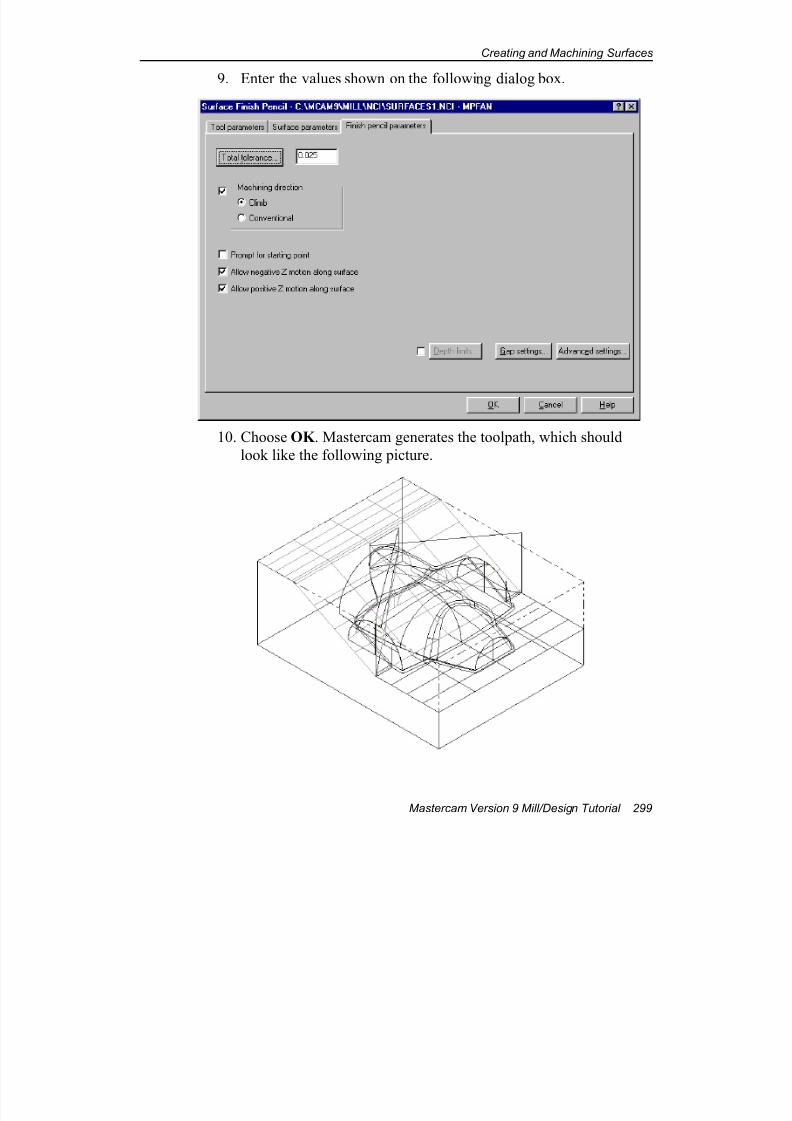
7/18/2019 V9 Mill-Design Tutorial (metric).pdf
http://slidepdf.com/reader/full/v9-mill-design-tutorial-metricpdf 311/453
Creating and Machining Surfaces
Mastercam Version 9 Mill/Design Tutorial 299
9. Enter the values shown on the following dialog box.
10. Choose OK . Mastercam generates the toolpath, which should
look like the following picture.
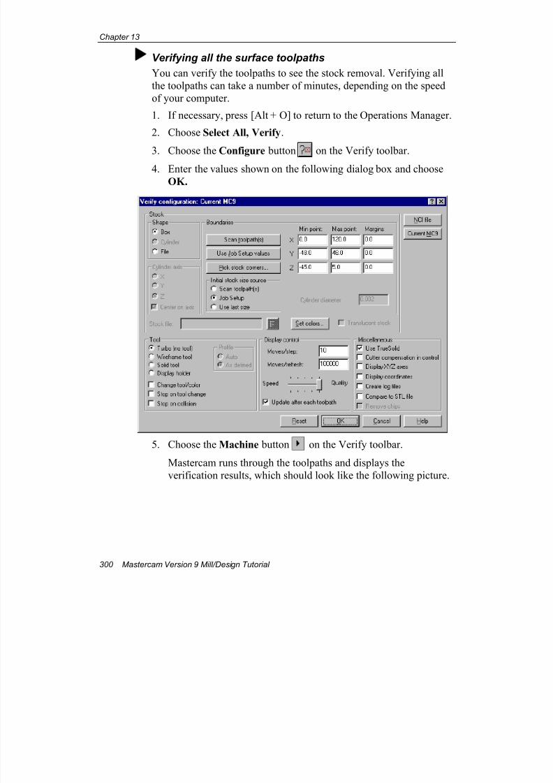
7/18/2019 V9 Mill-Design Tutorial (metric).pdf
http://slidepdf.com/reader/full/v9-mill-design-tutorial-metricpdf 312/453
Chapter 13
300 Mastercam Version 9 Mill/Design Tutorial
Verifying all the surface toolpaths
You can verify the toolpaths to see the stock removal. Verifying all
the toolpaths can take a number of minutes, depending on the speed
of your computer.
1. If necessary, press [Alt + O] to return to the Operations Manager.
2. Choose Select All, Verify.3. Choose the Configure button on the Verify toolbar.
4. Enter the values shown on the following dialog box and choose
OK.
5. Choose the Machine button on the Verify toolbar.
Mastercam runs through the toolpaths and displays the
verification results, which should look like the following picture.

7/18/2019 V9 Mill-Design Tutorial (metric).pdf
http://slidepdf.com/reader/full/v9-mill-design-tutorial-metricpdf 313/453
Creating and Machining Surfaces
Mastercam Version 9 Mill/Design Tutorial 301
6. Choose the Close button on the Verify toolbar to return to the
Operations Manager.
7. Choose OK to close the Operations Manager.
8. Press [Alt + A] to save the file.
Now that you have experience with creating surface toolpaths, the next
two chapters will show you more types of surface toolpaths and their
applications.

7/18/2019 V9 Mill-Design Tutorial (metric).pdf
http://slidepdf.com/reader/full/v9-mill-design-tutorial-metricpdf 314/453
Chapter 13
302 Mastercam Version 9 Mill/Design Tutorial
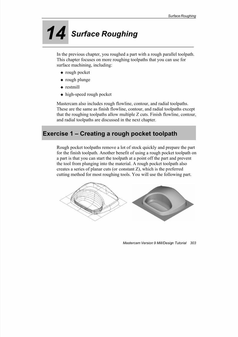
7/18/2019 V9 Mill-Design Tutorial (metric).pdf
http://slidepdf.com/reader/full/v9-mill-design-tutorial-metricpdf 315/453
Surface Roughing
Mastercam Version 9 Mill/Design Tutorial 303
14 Surface Roughing
In the previous chapter, you roughed a part with a rough parallel toolpath.
This chapter focuses on more roughing toolpaths that you can use forsurface machining, including:
rough pocket
rough plunge
restmill
high-speed rough pocket
Mastercam also includes rough flowline, contour, and radial toolpaths.
These are the same as finish flowline, contour, and radial toolpaths except
that the roughing toolpaths allow multiple Z cuts. Finish flowline, contour,
and radial toolpaths are discussed in the next chapter.
Exercise 1 – Creating a rough pocket toolpath
Rough pocket toolpaths remove a lot of stock quickly and prepare the part
for the finish toolpath. Another benefit of using a rough pocket toolpath on
a part is that you can start the toolpath at a point off the part and prevent
the tool from plunging into the material. A rough pocket toolpath also
creates a series of planar cuts (or constant Z), which is the preferred
cutting method for most roughing tools. You will use the following part.
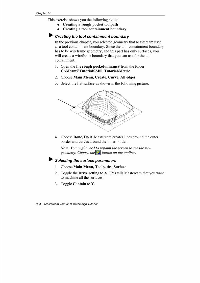
7/18/2019 V9 Mill-Design Tutorial (metric).pdf
http://slidepdf.com/reader/full/v9-mill-design-tutorial-metricpdf 316/453
Chapter 14
304 Mastercam Version 9 Mill/Design Tutorial
This exercise shows you the following skills:
Creating a rough pocket toolpath
Creating a tool containment boundary
Creating the tool containment boundary
In the previous chapter, you selected geometry that Mastercam used
as a tool containment boundary. Since the tool containment boundary
has to be wireframe geometry, and this part has only surfaces, you
will create a wireframe boundary that you can use for the tool
containment.
1. Open the file rough pocket-mm.mc9 from the folder
C:\Mcam9\Tutorials\Mill Tutorial\Metric.
2. Choose Main Menu, Create, Curve, All edges.
3. Select the flat surface as shown in the following picture.
4. Choose Done, Do it. Mastercam creates lines around the outer
border and curves around the inner border.
Note: You might need to repaint the screen to see the new geometry. Choose the button on the toolbar.
Selecting the surface parameters
1. Choose Main Menu, Toolpaths, Surface.
2. Toggle the Drive setting to A. This tells Mastercam that you want
to machine all the surfaces.
3. Toggle Contain to Y.
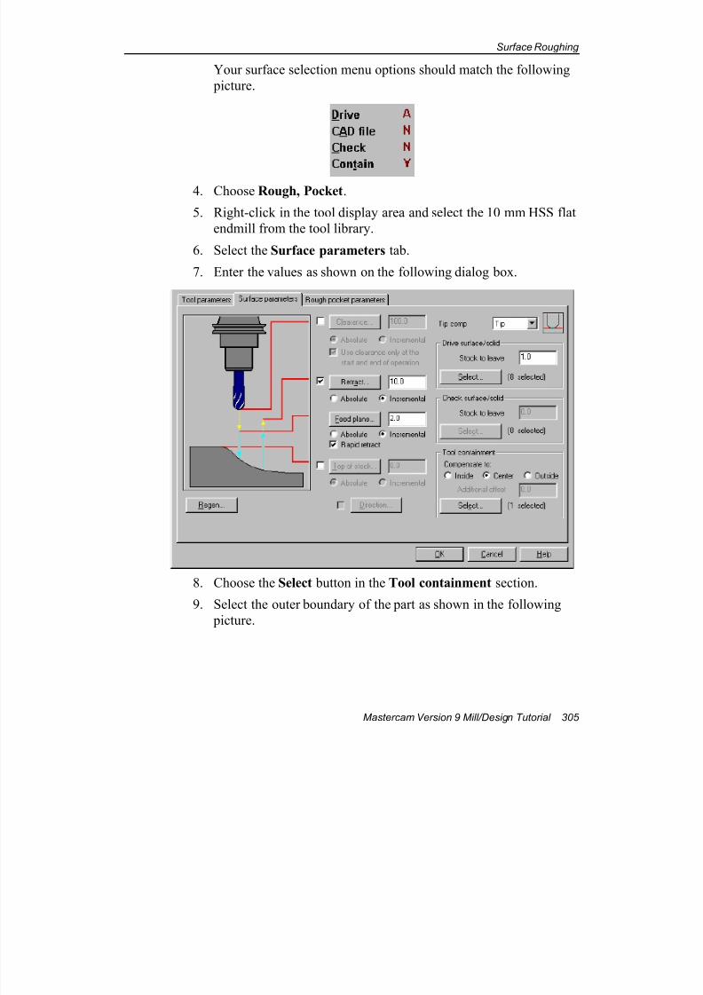
7/18/2019 V9 Mill-Design Tutorial (metric).pdf
http://slidepdf.com/reader/full/v9-mill-design-tutorial-metricpdf 317/453
Surface Roughing
Mastercam Version 9 Mill/Design Tutorial 305
Your surface selection menu options should match the following
picture.
4. Choose Rough, Pocket.
5. Right-click in the tool display area and select the 10 mm HSS flat
endmill from the tool library.
6. Select the Surface parameters tab.
7. Enter the values as shown on the following dialog box.
8. Choose the Select button in the Tool containment section.
9. Select the outer boundary of the part as shown in the following
picture.
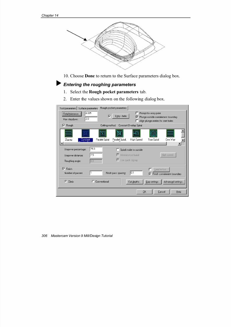
7/18/2019 V9 Mill-Design Tutorial (metric).pdf
http://slidepdf.com/reader/full/v9-mill-design-tutorial-metricpdf 318/453
Chapter 14
306 Mastercam Version 9 Mill/Design Tutorial
10. Choose Done to return to the Surface parameters dialog box.
Entering the roughing parameters
1. Select the Rough pocket parameters tab.
2. Enter the values shown on the following dialog box.
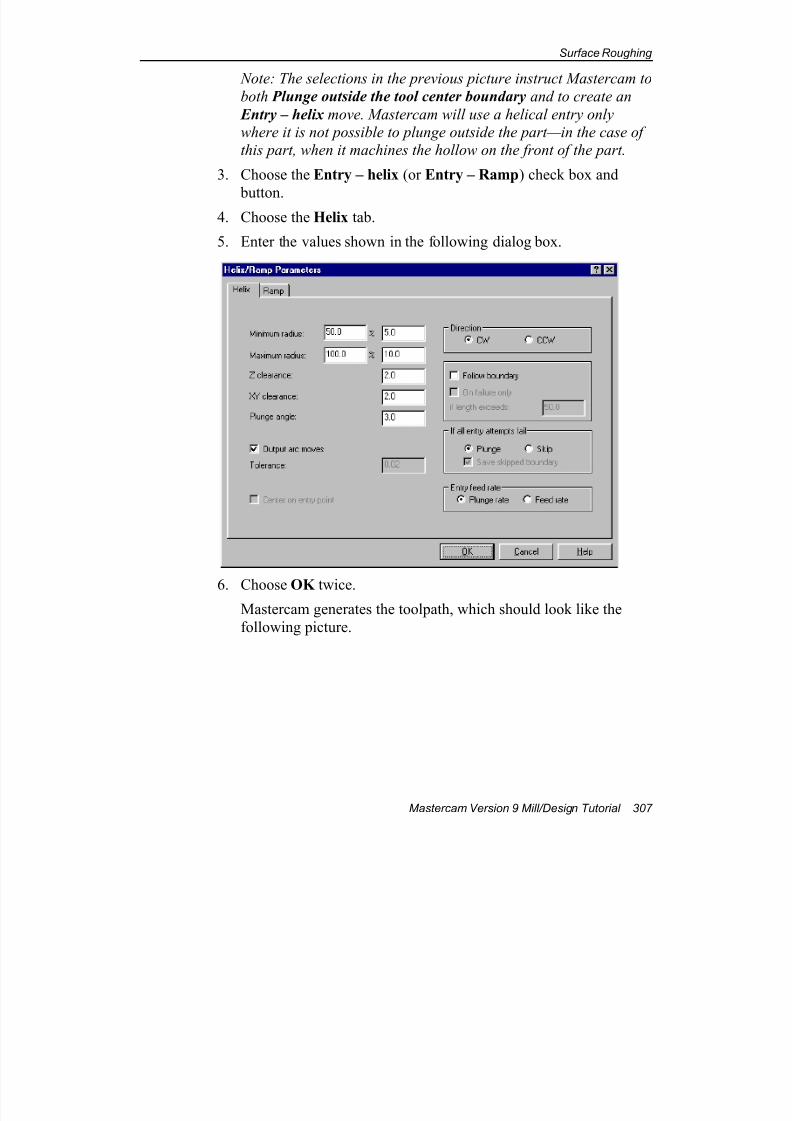
7/18/2019 V9 Mill-Design Tutorial (metric).pdf
http://slidepdf.com/reader/full/v9-mill-design-tutorial-metricpdf 319/453
Surface Roughing
Mastercam Version 9 Mill/Design Tutorial 307
Note: The selections in the previous picture instruct Mastercam to
both Plunge outside the tool center boundary and to create an
Entry – helix move. Mastercam will use a helical entry only
where it is not possible to plunge outside the part—in the case of
this part, when it machines the hollow on the front of the part.
3. Choose the Entry – helix (or Entry – Ramp) check box and
button.4. Choose the Helix tab.
5. Enter the values shown in the following dialog box.
6. Choose OK twice.Mastercam generates the toolpath, which should look like the
following picture.
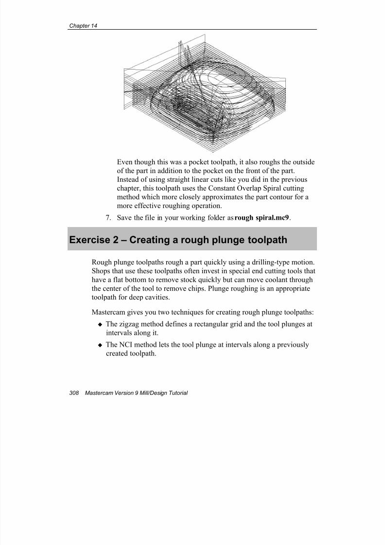
7/18/2019 V9 Mill-Design Tutorial (metric).pdf
http://slidepdf.com/reader/full/v9-mill-design-tutorial-metricpdf 320/453
Chapter 14
308 Mastercam Version 9 Mill/Design Tutorial
Even though this was a pocket toolpath, it also roughs the outside
of the part in addition to the pocket on the front of the part.
Instead of using straight linear cuts like you did in the previous
chapter, this toolpath uses the Constant Overlap Spiral cuttingmethod which more closely approximates the part contour for a
more effective roughing operation.
7. Save the file in your working folder as rough spiral.mc9.
Exercise 2 – Creating a rough plunge toolpath
Rough plunge toolpaths rough a part quickly using a drilling-type motion.
Shops that use these toolpaths often invest in special end cutting tools that
have a flat bottom to remove stock quickly but can move coolant through
the center of the tool to remove chips. Plunge roughing is an appropriatetoolpath for deep cavities.
Mastercam gives you two techniques for creating rough plunge toolpaths:
The zigzag method defines a rectangular grid and the tool plunges at
intervals along it.
The NCI method lets the tool plunge at intervals along a previously
created toolpath.
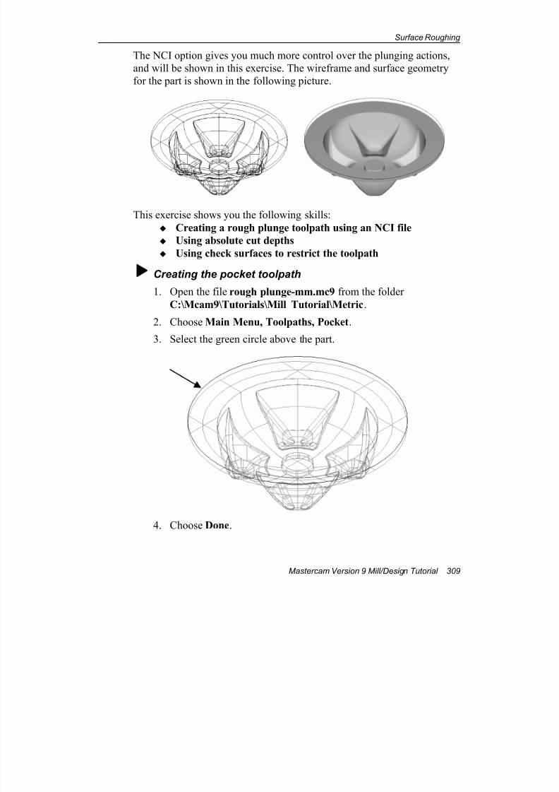
7/18/2019 V9 Mill-Design Tutorial (metric).pdf
http://slidepdf.com/reader/full/v9-mill-design-tutorial-metricpdf 321/453
Surface Roughing
Mastercam Version 9 Mill/Design Tutorial 309
The NCI option gives you much more control over the plunging actions,
and will be shown in this exercise. The wireframe and surface geometry
for the part is shown in the following picture.
This exercise shows you the following skills:
Creating a rough plunge toolpath using an NCI file
Using absolute cut depths
Using check surfaces to restrict the toolpath
Creating the pocket toolpath1. Open the file rough plunge-mm.mc9 from the folder
C:\Mcam9\Tutorials\Mill Tutorial\Metric.
2. Choose Main Menu, Toolpaths, Pocket.
3. Select the green circle above the part.
4. Choose Done.
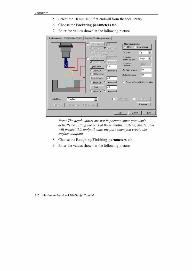
7/18/2019 V9 Mill-Design Tutorial (metric).pdf
http://slidepdf.com/reader/full/v9-mill-design-tutorial-metricpdf 322/453
Chapter 14
310 Mastercam Version 9 Mill/Design Tutorial
5. Select the 10 mm HSS flat endmill from the tool library.
6. Choose the Pocketing parameters tab.
7. Enter the values shown in the following picture.
Note: The depth values are not important, since you won't
actually be cutting the part at these depths. Instead, Mastercam
will project this toolpath onto the part when you create the
surface toolpath.
8. Choose the Roughing/Finishing parameters tab.
9. Enter the values shown in the following picture.
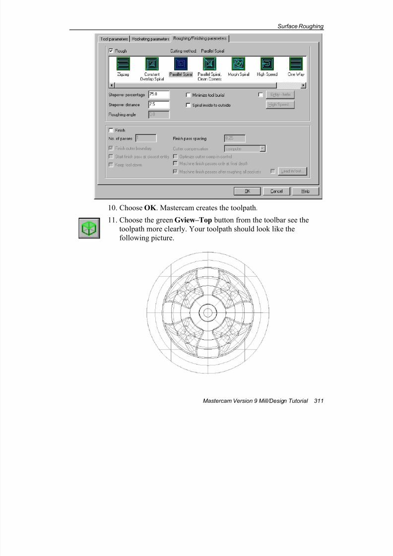
7/18/2019 V9 Mill-Design Tutorial (metric).pdf
http://slidepdf.com/reader/full/v9-mill-design-tutorial-metricpdf 323/453
Surface Roughing
Mastercam Version 9 Mill/Design Tutorial 311
10. Choose OK . Mastercam creates the toolpath.
11. Choose the green Gview–Top button from the toolbar see the
toolpath more clearly. Your toolpath should look like the
following picture.
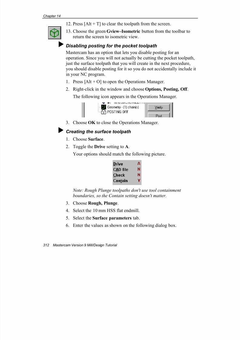
7/18/2019 V9 Mill-Design Tutorial (metric).pdf
http://slidepdf.com/reader/full/v9-mill-design-tutorial-metricpdf 324/453
Chapter 14
312 Mastercam Version 9 Mill/Design Tutorial
12. Press [Alt + T] to clear the toolpath from the screen.
13. Choose the green Gview–Isometric button from the toolbar to
return the screen to isometric view.
Disabling posting for the pocket toolpath
Mastercam has an option that lets you disable posting for an
operation. Since you will not actually be cutting the pocket toolpath, just the surface toolpath that you will create in the next procedure,
you should disable posting for it so you do not accidentally include it
in your NC program.
1. Press [Alt + O] to open the Operations Manager.
2. Right-click in the window and choose Options, Posting, Off .
The following icon appears in the Operations Manager.
3. Choose OK to close the Operations Manager.
Creating the surface toolpath
1. Choose Surface.
2. Toggle the Drive setting to A.
Your options should match the following picture.
Note: Rough Plunge toolpaths don't use tool containment
boundaries, so the Contain setting doesn't matter.
3. Choose Rough, Plunge.
4. Select the 10 mm HSS flat endmill.
5. Select the Surface parameters tab.
6. Enter the values as shown on the following dialog box.
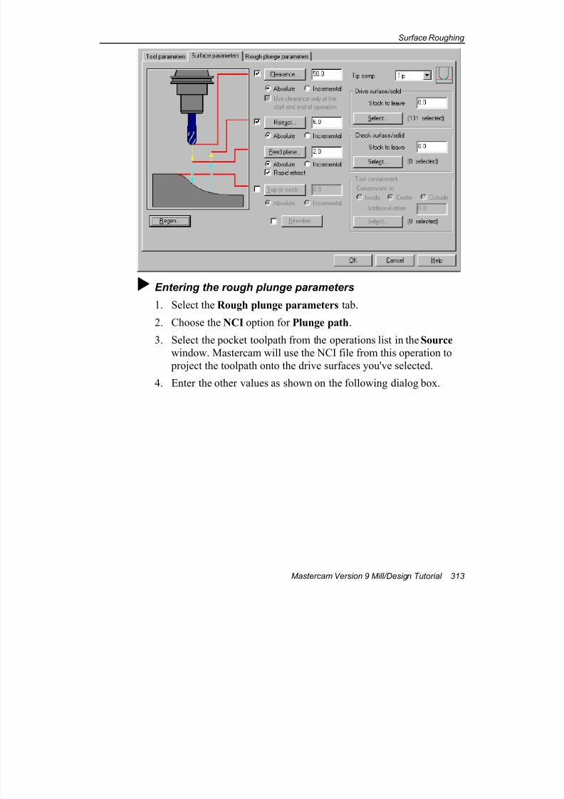
7/18/2019 V9 Mill-Design Tutorial (metric).pdf
http://slidepdf.com/reader/full/v9-mill-design-tutorial-metricpdf 325/453
Surface Roughing
Mastercam Version 9 Mill/Design Tutorial 313
Entering the rough plunge parameters
1. Select the Rough plunge parameters tab.
2. Choose the NCI option for Plunge path.
3. Select the pocket toolpath from the operations list in the Source
window. Mastercam will use the NCI file from this operation to
project the toolpath onto the drive surfaces you've selected.
4. Enter the other values as shown on the following dialog box.
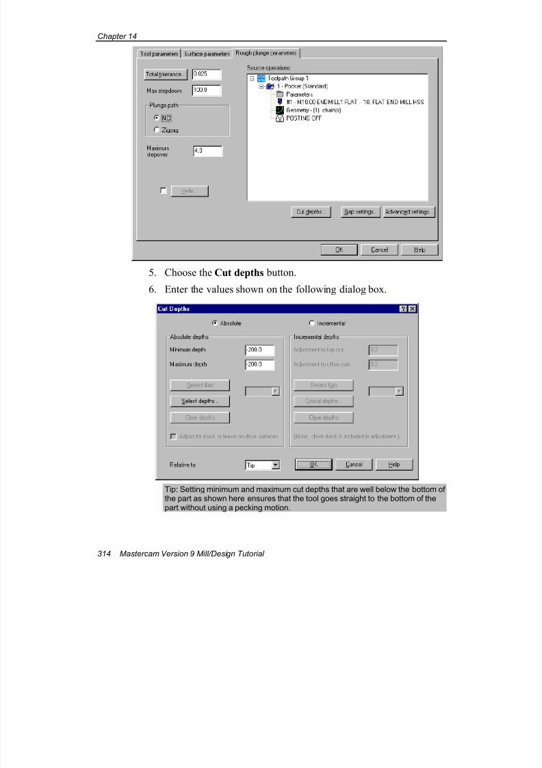
7/18/2019 V9 Mill-Design Tutorial (metric).pdf
http://slidepdf.com/reader/full/v9-mill-design-tutorial-metricpdf 326/453
Chapter 14
314 Mastercam Version 9 Mill/Design Tutorial
5. Choose the Cut depths button.
6. Enter the values shown on the following dialog box.
Tip: Setting minimum and maximum cut depths that are well below the bottom ofthe part as shown here ensures that the tool goes straight to the bottom of thepart without using a pecking motion.
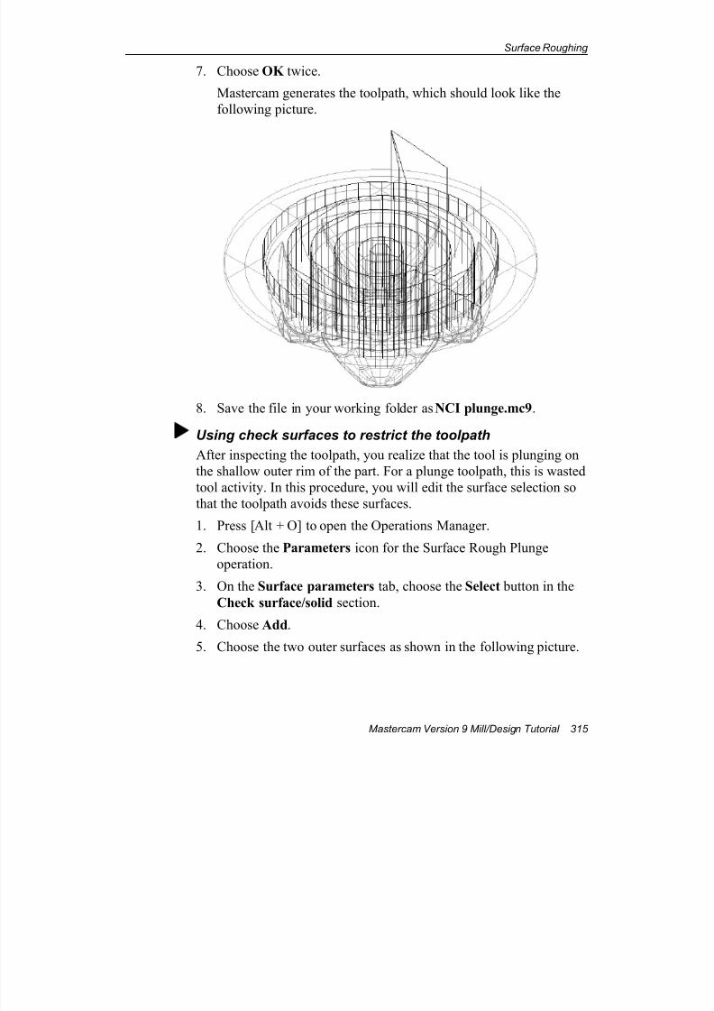
7/18/2019 V9 Mill-Design Tutorial (metric).pdf
http://slidepdf.com/reader/full/v9-mill-design-tutorial-metricpdf 327/453
Surface Roughing
Mastercam Version 9 Mill/Design Tutorial 315
7. Choose OK twice.
Mastercam generates the toolpath, which should look like the
following picture.
8. Save the file in your working folder as NCI plunge.mc9.
Using check surfaces to restrict the toolpath
After inspecting the toolpath, you realize that the tool is plunging on
the shallow outer rim of the part. For a plunge toolpath, this is wasted
tool activity. In this procedure, you will edit the surface selection so
that the toolpath avoids these surfaces.
1. Press [Alt + O] to open the Operations Manager.2. Choose the Parameters icon for the Surface Rough Plunge
operation.
3. On the Surface parameters tab, choose the Select button in the
Check surface/solid section.
4. Choose Add.
5. Choose the two outer surfaces as shown in the following picture.
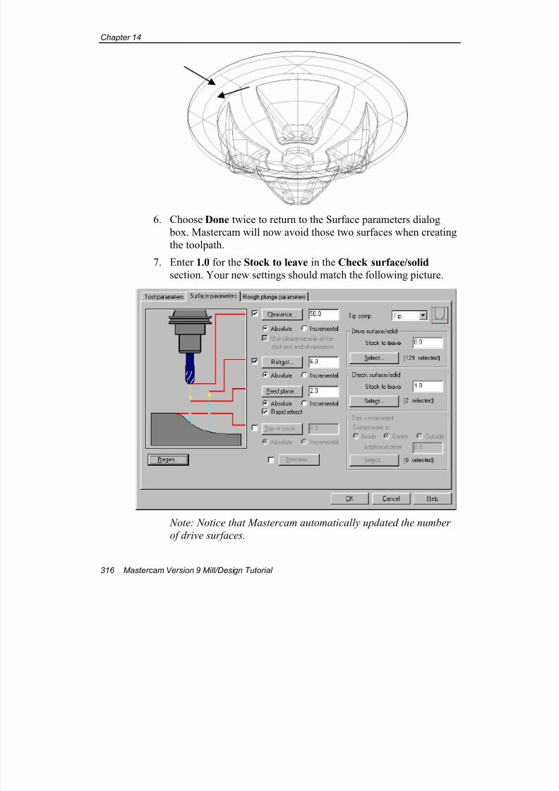
7/18/2019 V9 Mill-Design Tutorial (metric).pdf
http://slidepdf.com/reader/full/v9-mill-design-tutorial-metricpdf 328/453
Chapter 14
316 Mastercam Version 9 Mill/Design Tutorial
6. Choose Done twice to return to the Surface parameters dialog
box. Mastercam will now avoid those two surfaces when creating
the toolpath.
7. Enter 1.0 for the Stock to leave in the Check surface/solid
section. Your new settings should match the following picture.
Note: Notice that Mastercam automatically updated the number
of drive surfaces.
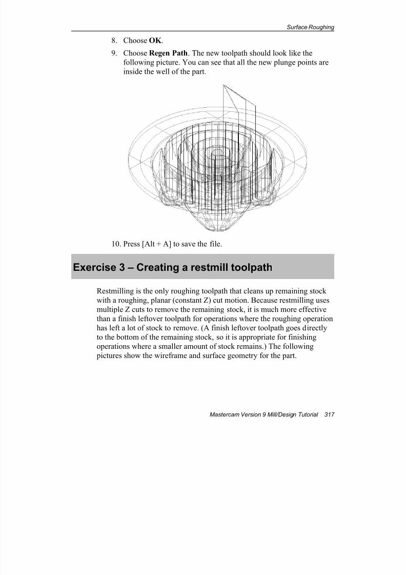
7/18/2019 V9 Mill-Design Tutorial (metric).pdf
http://slidepdf.com/reader/full/v9-mill-design-tutorial-metricpdf 329/453
Surface Roughing
Mastercam Version 9 Mill/Design Tutorial 317
8. Choose OK .
9. Choose Regen Path. The new toolpath should look like the
following picture. You can see that all the new plunge points are
inside the well of the part.
10. Press [Alt + A] to save the file.
Exercise 3 – Creating a restmill toolpath
Restmilling is the only roughing toolpath that cleans up remaining stock
with a roughing, planar (constant Z) cut motion. Because restmilling usesmultiple Z cuts to remove the remaining stock, it is much more effective
than a finish leftover toolpath for operations where the roughing operation
has left a lot of stock to remove. (A finish leftover toolpath goes directly
to the bottom of the remaining stock, so it is appropriate for finishing
operations where a smaller amount of stock remains.) The following
pictures show the wireframe and surface geometry for the part.
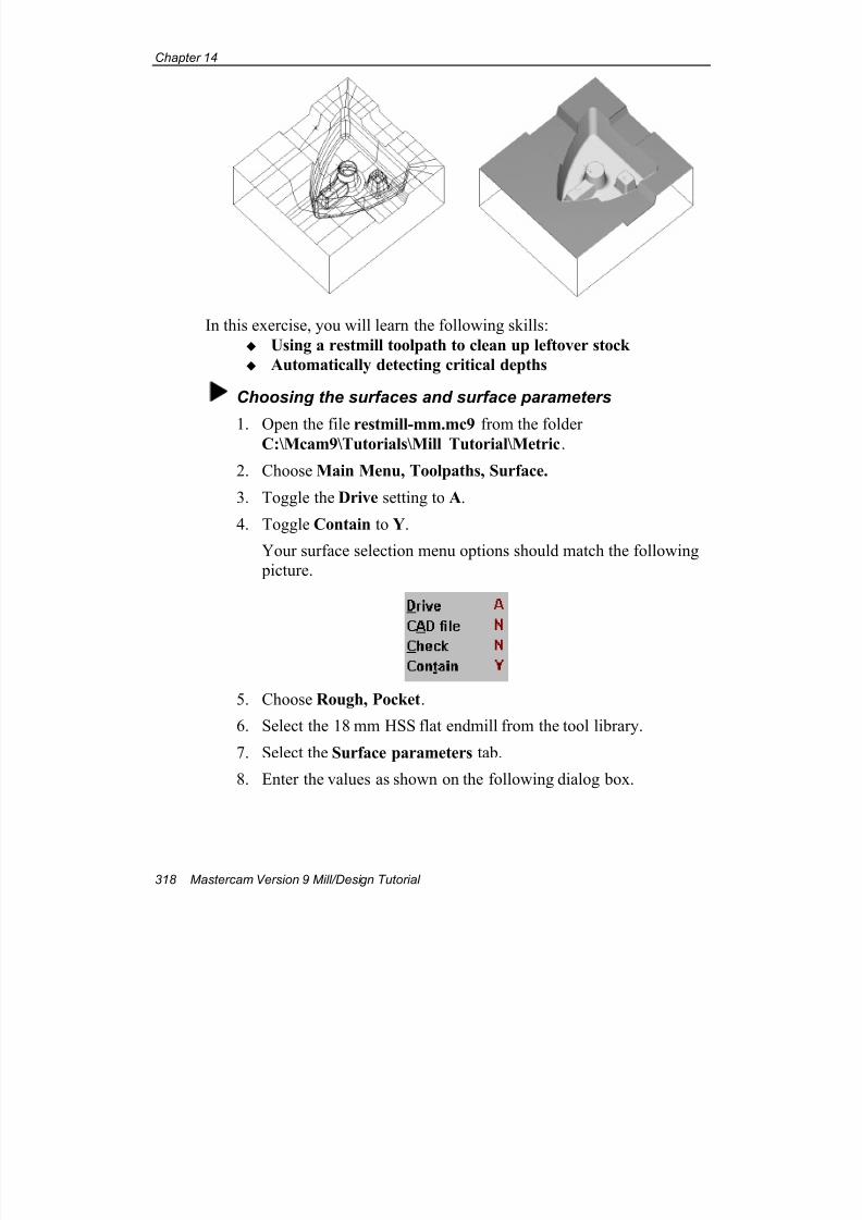
7/18/2019 V9 Mill-Design Tutorial (metric).pdf
http://slidepdf.com/reader/full/v9-mill-design-tutorial-metricpdf 330/453
Chapter 14
318 Mastercam Version 9 Mill/Design Tutorial
In this exercise, you will learn the following skills:
Using a restmill toolpath to clean up leftover stock
Automatically detecting critical depths
Choosing the surfaces and surface parameters
1. Open the file restmill-mm.mc9 from the folderC:\Mcam9\Tutorials\Mill Tutorial\Metric.
2. Choose Main Menu, Toolpaths, Surface.
3. Toggle the Drive setting to A.
4. Toggle Contain to Y.
Your surface selection menu options should match the following
picture.
5. Choose Rough, Pocket.
6. Select the 18 mm HSS flat endmill from the tool library.
7. Select the Surface parameters tab.
8. Enter the values as shown on the following dialog box.
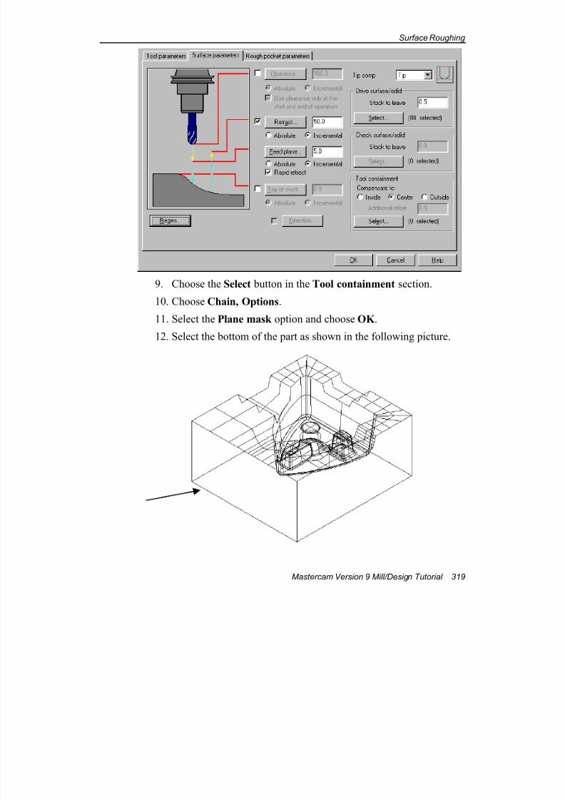
7/18/2019 V9 Mill-Design Tutorial (metric).pdf
http://slidepdf.com/reader/full/v9-mill-design-tutorial-metricpdf 331/453
Surface Roughing
Mastercam Version 9 Mill/Design Tutorial 319
9. Choose the Select button in the Tool containment section.
10. Choose Chain, Options.
11. Select the Plane mask option and choose OK .
12. Select the bottom of the part as shown in the following picture.
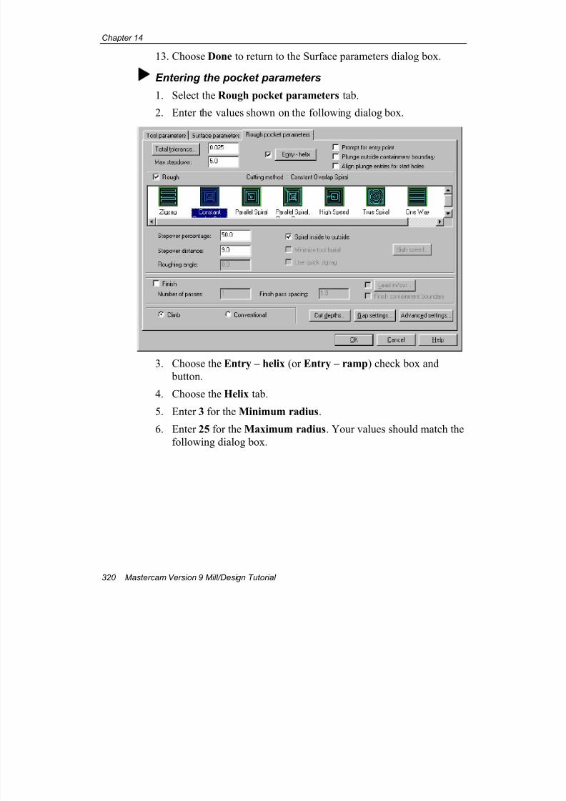
7/18/2019 V9 Mill-Design Tutorial (metric).pdf
http://slidepdf.com/reader/full/v9-mill-design-tutorial-metricpdf 332/453
Chapter 14
320 Mastercam Version 9 Mill/Design Tutorial
13. Choose Done to return to the Surface parameters dialog box.
Entering the pocket parameters
1. Select the Rough pocket parameters tab.
2. Enter the values shown on the following dialog box.
3. Choose the Entry – helix (or Entry – ramp) check box and
button.
4. Choose the Helix tab.
5. Enter 3 for the Minimum radius.
6. Enter 25 for the Maximum radius. Your values should match the
following dialog box.
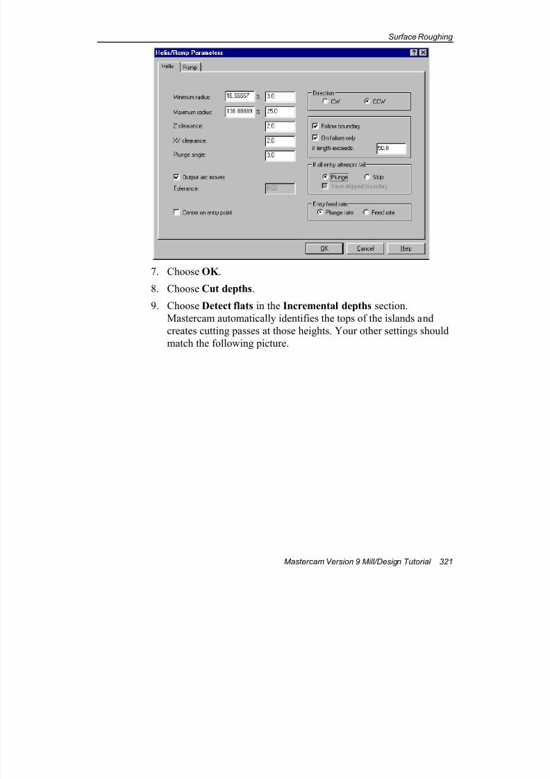
7/18/2019 V9 Mill-Design Tutorial (metric).pdf
http://slidepdf.com/reader/full/v9-mill-design-tutorial-metricpdf 333/453
Surface Roughing
Mastercam Version 9 Mill/Design Tutorial 321
7. Choose OK .8. Choose Cut depths.
9. Choose Detect flats in the Incremental depths section.
Mastercam automatically identifies the tops of the islands and
creates cutting passes at those heights. Your other settings should
match the following picture.
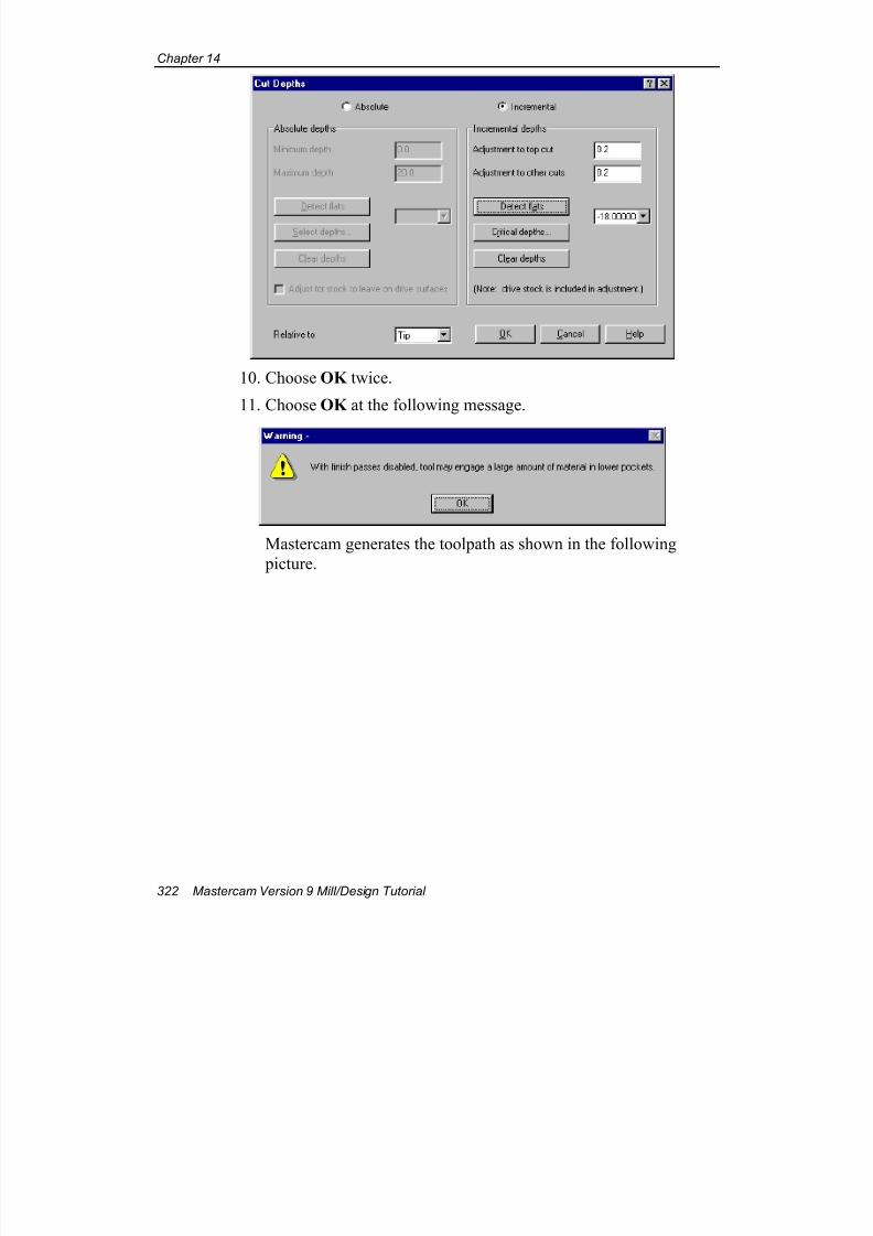
7/18/2019 V9 Mill-Design Tutorial (metric).pdf
http://slidepdf.com/reader/full/v9-mill-design-tutorial-metricpdf 334/453
Chapter 14
322 Mastercam Version 9 Mill/Design Tutorial
10. Choose OK twice.
11. Choose OK at the following message.
Mastercam generates the toolpath as shown in the following
picture.
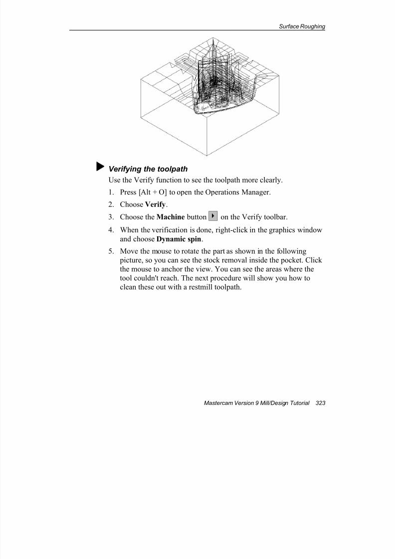
7/18/2019 V9 Mill-Design Tutorial (metric).pdf
http://slidepdf.com/reader/full/v9-mill-design-tutorial-metricpdf 335/453
Surface Roughing
Mastercam Version 9 Mill/Design Tutorial 323
Verifying the toolpath
Use the Verify function to see the toolpath more clearly.
1. Press [Alt + O] to open the Operations Manager.2. Choose Verify.
3. Choose the Machine button on the Verify toolbar.
4. When the verification is done, right-click in the graphics window
and choose Dynamic spin.
5. Move the mouse to rotate the part as shown in the following
picture, so you can see the stock removal inside the pocket. Click
the mouse to anchor the view. You can see the areas where the
tool couldn't reach. The next procedure will show you how to
clean these out with a restmill toolpath.
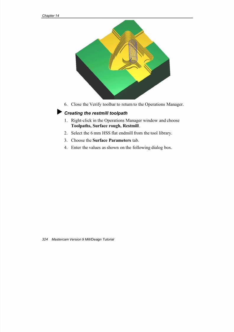
7/18/2019 V9 Mill-Design Tutorial (metric).pdf
http://slidepdf.com/reader/full/v9-mill-design-tutorial-metricpdf 336/453
Chapter 14
324 Mastercam Version 9 Mill/Design Tutorial
6. Close the Verify toolbar to return to the Operations Manager.
Creating the restmill toolpath
1. Right-click in the Operations Manager window and choose
Toolpaths, Surface rough, Restmill.
2. Select the 6 mm HSS flat endmill from the tool library.
3. Choose the Surface Parameters tab.
4. Enter the values as shown on the following dialog box.
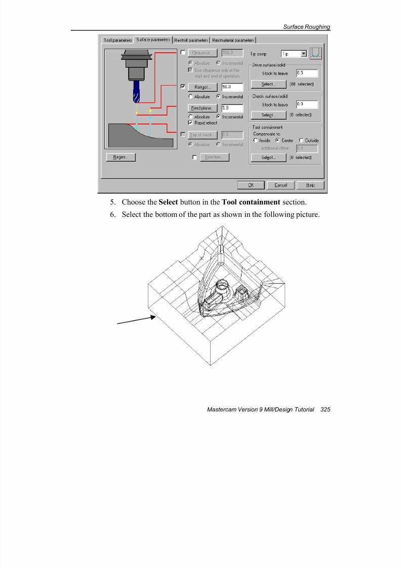
7/18/2019 V9 Mill-Design Tutorial (metric).pdf
http://slidepdf.com/reader/full/v9-mill-design-tutorial-metricpdf 337/453
Surface Roughing
Mastercam Version 9 Mill/Design Tutorial 325
5. Choose the Select button in the Tool containment section.
6. Select the bottom of the part as shown in the following picture.
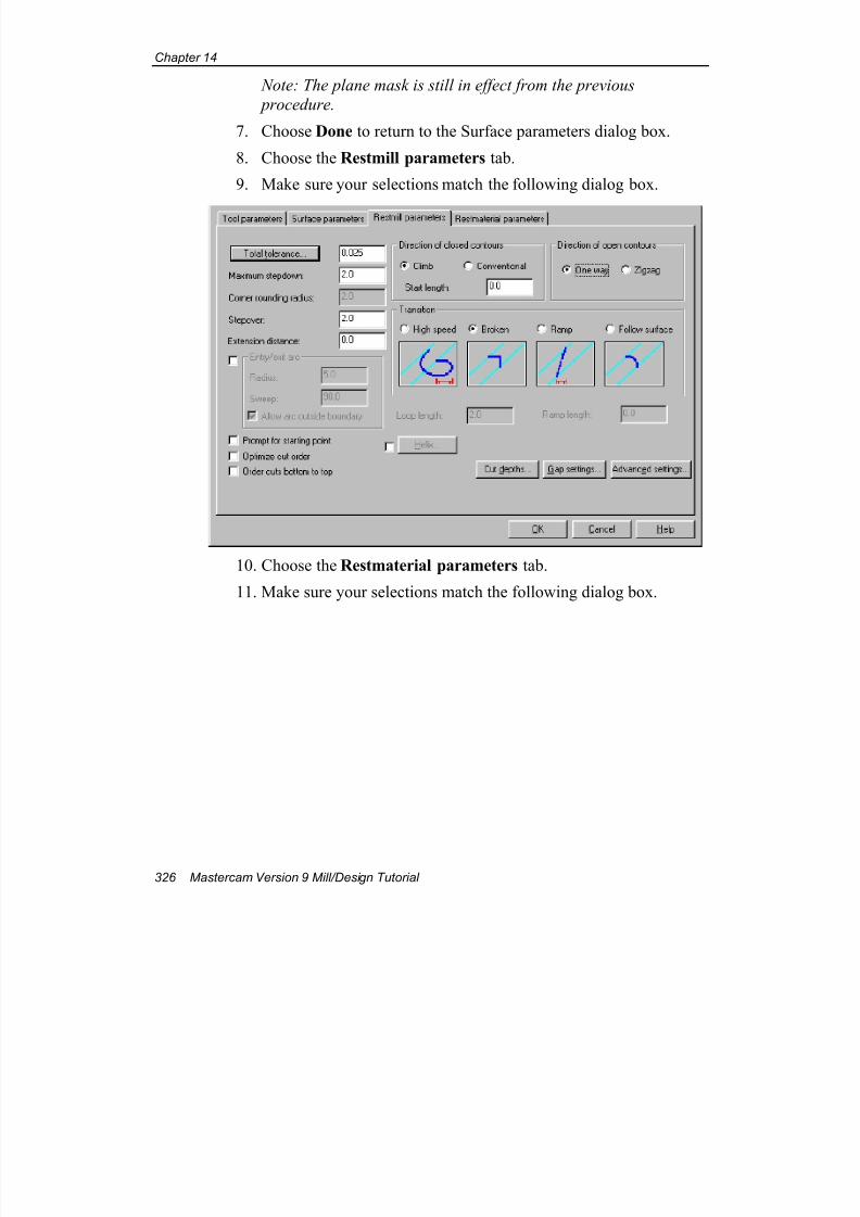
7/18/2019 V9 Mill-Design Tutorial (metric).pdf
http://slidepdf.com/reader/full/v9-mill-design-tutorial-metricpdf 338/453
Chapter 14
326 Mastercam Version 9 Mill/Design Tutorial
Note: The plane mask is still in effect from the previous
procedure.
7. Choose Done to return to the Surface parameters dialog box.
8. Choose the Restmill parameters tab.
9. Make sure your selections match the following dialog box.
10. Choose the Restmaterial parameters tab.
11. Make sure your selections match the following dialog box.
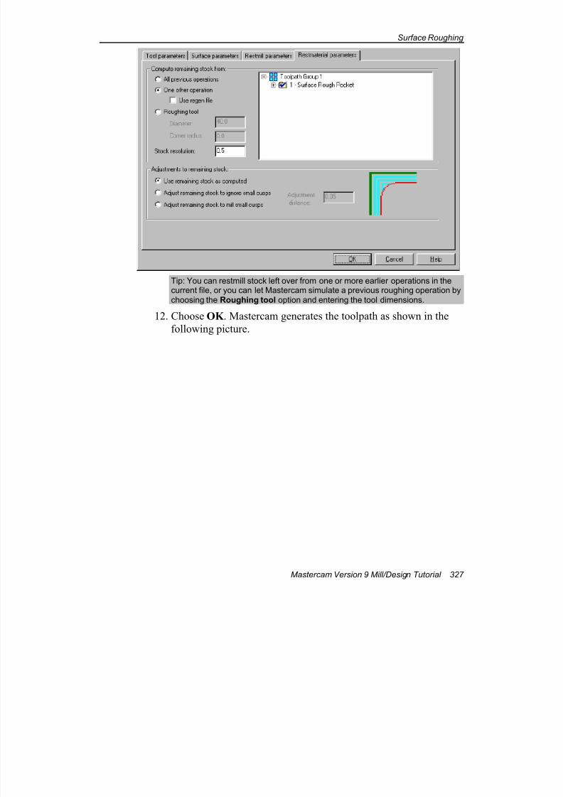
7/18/2019 V9 Mill-Design Tutorial (metric).pdf
http://slidepdf.com/reader/full/v9-mill-design-tutorial-metricpdf 339/453
Surface Roughing
Mastercam Version 9 Mill/Design Tutorial 327
Tip: You can restmill stock left over from one or more earlier operations in thecurrent file, or you can let Mastercam simulate a previous roughing operation bychoosing the Roughing tool option and entering the tool dimensions.
12. Choose OK . Mastercam generates the toolpath as shown in the
following picture.
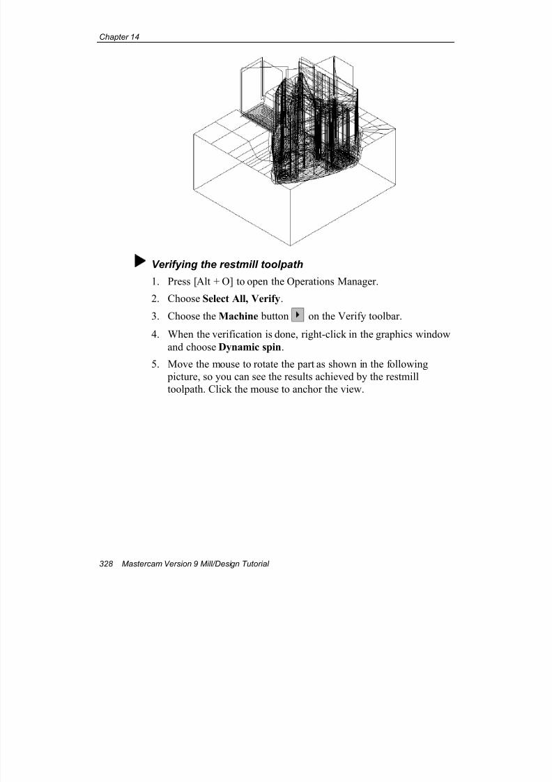
7/18/2019 V9 Mill-Design Tutorial (metric).pdf
http://slidepdf.com/reader/full/v9-mill-design-tutorial-metricpdf 340/453
Chapter 14
328 Mastercam Version 9 Mill/Design Tutorial
Verifying the restmill toolpath
1. Press [Alt + O] to open the Operations Manager.
2. Choose Select All, Verify.
3. Choose the Machine button on the Verify toolbar.
4. When the verification is done, right-click in the graphics window
and choose Dynamic spin.
5. Move the mouse to rotate the part as shown in the following
picture, so you can see the results achieved by the restmill
toolpath. Click the mouse to anchor the view.
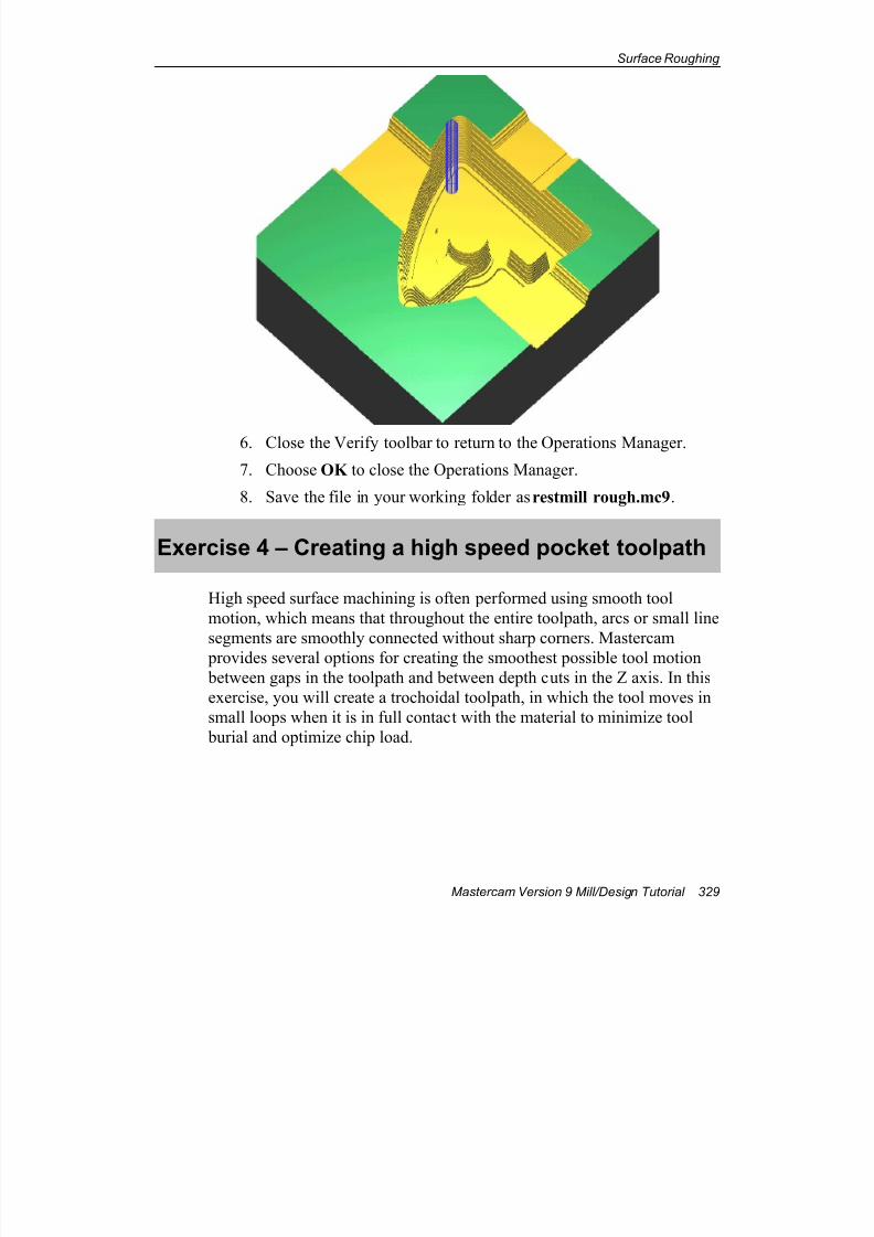
7/18/2019 V9 Mill-Design Tutorial (metric).pdf
http://slidepdf.com/reader/full/v9-mill-design-tutorial-metricpdf 341/453
Surface Roughing
Mastercam Version 9 Mill/Design Tutorial 329
6. Close the Verify toolbar to return to the Operations Manager.
7. Choose OK to close the Operations Manager.
8. Save the file in your working folder as restmill rough.mc9.
Exercise 4 – Creating a high speed pocket toolpath
High speed surface machining is often performed using smooth tool
motion, which means that throughout the entire toolpath, arcs or small line
segments are smoothly connected without sharp corners. Mastercam
provides several options for creating the smoothest possible tool motion
between gaps in the toolpath and between depth cuts in the Z axis. In this
exercise, you will create a trochoidal toolpath, in which the tool moves in
small loops when it is in full contact with the material to minimize tool
burial and optimize chip load.
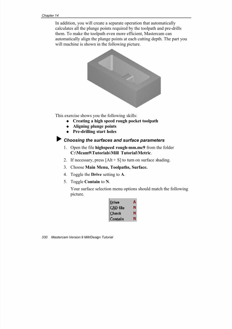
7/18/2019 V9 Mill-Design Tutorial (metric).pdf
http://slidepdf.com/reader/full/v9-mill-design-tutorial-metricpdf 342/453
Chapter 14
330 Mastercam Version 9 Mill/Design Tutorial
In addition, you will create a separate operation that automatically
calculates all the plunge points required by the toolpath and pre-drills
them. To make the toolpath even more efficient, Mastercam can
automatically align the plunge points at each cutting depth. The part you
will machine is shown in the following picture.
This exercise shows you the following skills: Creating a high speed rough pocket toolpath
Aligning plunge points
Pre-drilling start holes
Choosing the surfaces and surface parameters
1. Open the file highspeed rough-mm.mc9 from the folder
C:\Mcam9\Tutorials\Mill Tutorial\Metric.
2. If necessary, press [Alt + S] to turn on surface shading.
3. Choose Main Menu, Toolpaths, Surface.
4. Toggle the Drive setting to A.
5. Toggle Contain to N.
Your surface selection menu options should match the following
picture.
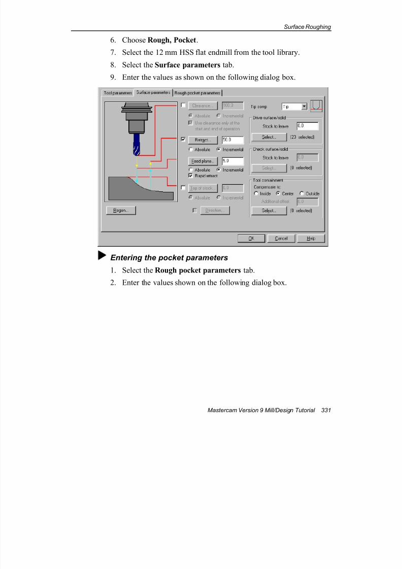
7/18/2019 V9 Mill-Design Tutorial (metric).pdf
http://slidepdf.com/reader/full/v9-mill-design-tutorial-metricpdf 343/453
Surface Roughing
Mastercam Version 9 Mill/Design Tutorial 331
6. Choose Rough, Pocket.
7. Select the 12 mm HSS flat endmill from the tool library.
8. Select the Surface parameters tab.
9. Enter the values as shown on the following dialog box.
Entering the pocket parameters
1. Select the Rough pocket parameters tab.
2. Enter the values shown on the following dialog box.
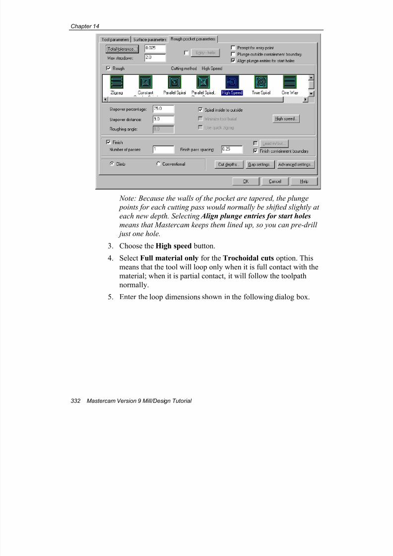
7/18/2019 V9 Mill-Design Tutorial (metric).pdf
http://slidepdf.com/reader/full/v9-mill-design-tutorial-metricpdf 344/453
Chapter 14
332 Mastercam Version 9 Mill/Design Tutorial
Note: Because the walls of the pocket are tapered, the plunge
points for each cutting pass would normally be shifted slightly at
each new depth. Selecting Align plunge entries for start holes
means that Mastercam keeps them lined up, so you can pre-drill
just one hole.
3. Choose the High speed button.
4. Select Full material only for the Trochoidal cuts option. This
means that the tool will loop only when it is full contact with the
material; when it is partial contact, it will follow the toolpath
normally.
5. Enter the loop dimensions shown in the following dialog box.
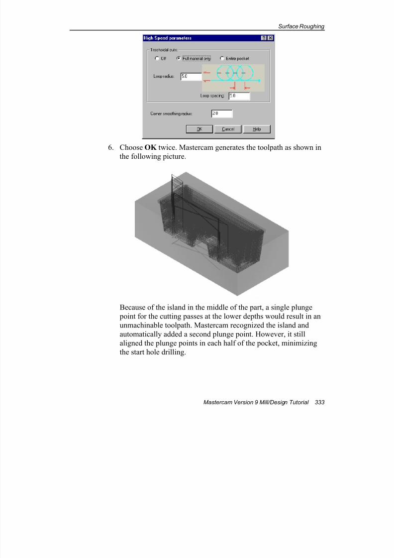
7/18/2019 V9 Mill-Design Tutorial (metric).pdf
http://slidepdf.com/reader/full/v9-mill-design-tutorial-metricpdf 345/453
Surface Roughing
Mastercam Version 9 Mill/Design Tutorial 333
6. Choose OK twice. Mastercam generates the toolpath as shown in
the following picture.
Because of the island in the middle of the part, a single plunge
point for the cutting passes at the lower depths would result in an
unmachinable toolpath. Mastercam recognized the island and
automatically added a second plunge point. However, it still
aligned the plunge points in each half of the pocket, minimizing
the start hole drilling.
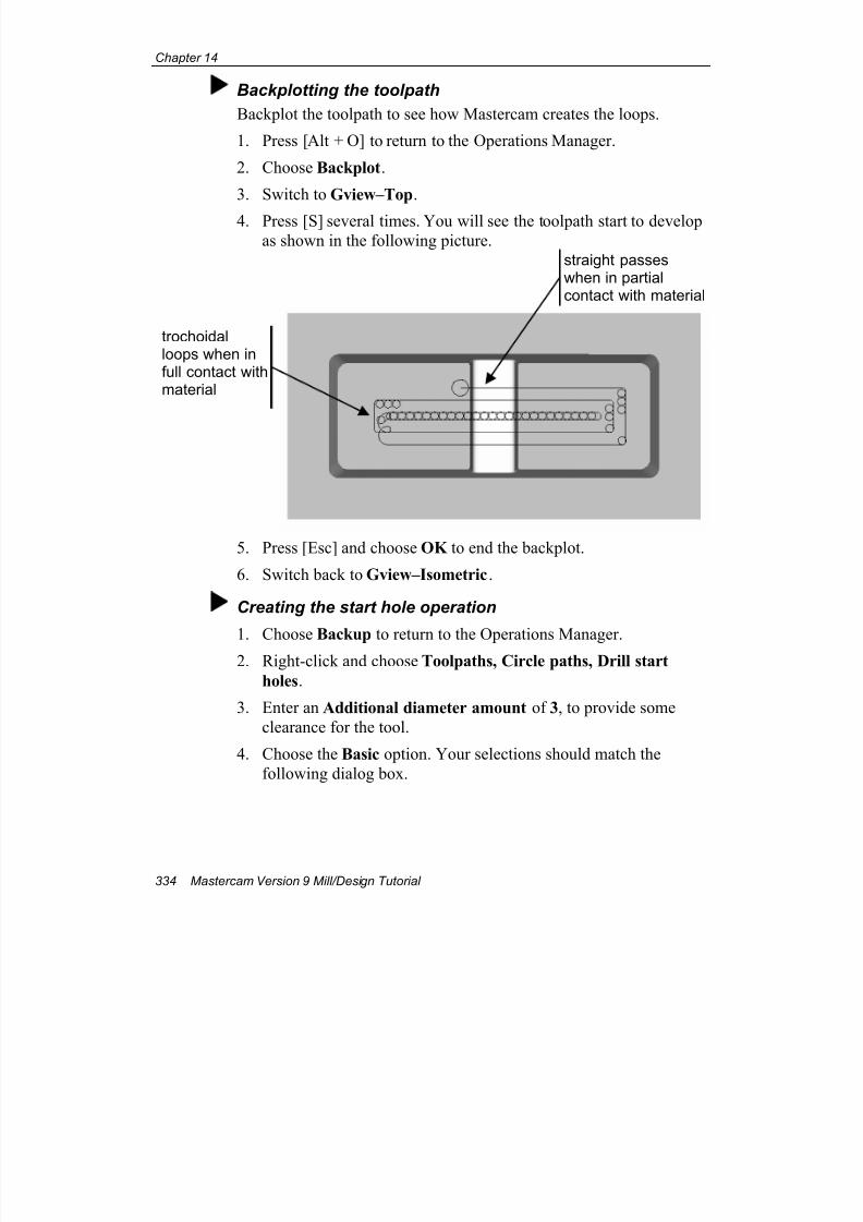
7/18/2019 V9 Mill-Design Tutorial (metric).pdf
http://slidepdf.com/reader/full/v9-mill-design-tutorial-metricpdf 346/453
Chapter 14
334 Mastercam Version 9 Mill/Design Tutorial
Backplotting the toolpath
Backplot the toolpath to see how Mastercam creates the loops.
1. Press [Alt + O] to return to the Operations Manager.
2. Choose Backplot.
3. Switch to Gview–Top.
4. Press [S] several times. You will see the toolpath start to develop
as shown in the following picture.
5. Press [Esc] and choose OK to end the backplot.
6. Switch back to Gview–Isometric.
Creating the start hole operation
1. Choose Backup to return to the Operations Manager.2. Right-click and choose Toolpaths, Circle paths, Drill start
holes.
3. Enter an Additional diameter amount of 3, to provide some
clearance for the tool.
4. Choose the Basic option. Your selections should match the
following dialog box.
trochoidalloops when infull contact withmaterial
straight passeswhen in partialcontact with material
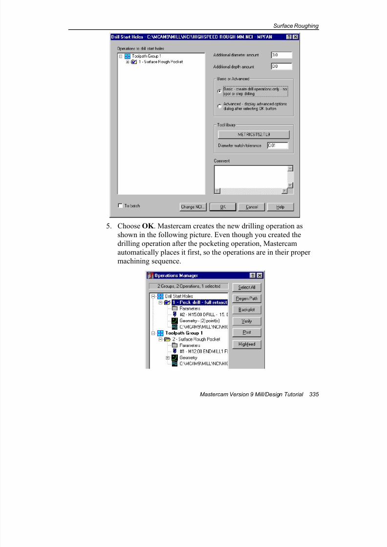
7/18/2019 V9 Mill-Design Tutorial (metric).pdf
http://slidepdf.com/reader/full/v9-mill-design-tutorial-metricpdf 347/453
Surface Roughing
Mastercam Version 9 Mill/Design Tutorial 335
5. Choose OK . Mastercam creates the new drilling operation as
shown in the following picture. Even though you created the
drilling operation after the pocketing operation, Mastercam
automatically places it first, so the operations are in their proper
machining sequence.
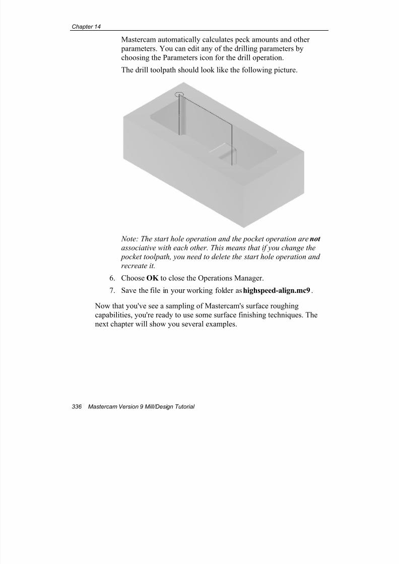
7/18/2019 V9 Mill-Design Tutorial (metric).pdf
http://slidepdf.com/reader/full/v9-mill-design-tutorial-metricpdf 348/453
Chapter 14
336 Mastercam Version 9 Mill/Design Tutorial
Mastercam automatically calculates peck amounts and other
parameters. You can edit any of the drilling parameters by
choosing the Parameters icon for the drill operation.
The drill toolpath should look like the following picture.
Note: The start hole operation and the pocket operation are not
associative with each other. This means that if you change the
pocket toolpath, you need to delete the start hole operation and
recreate it.
6. Choose OK to close the Operations Manager.
7. Save the file in your working folder as highspeed-align.mc9.
Now that you've see a sampling of Mastercam's surface roughing
capabilities, you're ready to use some surface finishing techniques. The
next chapter will show you several examples.
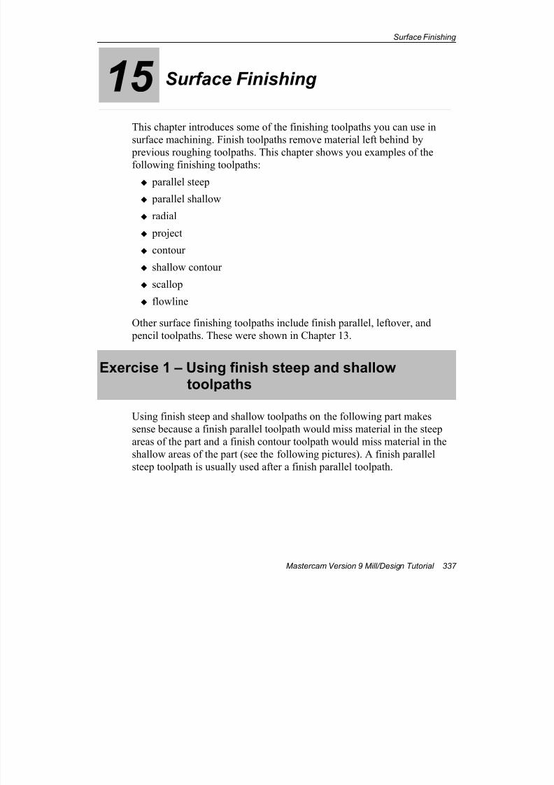
7/18/2019 V9 Mill-Design Tutorial (metric).pdf
http://slidepdf.com/reader/full/v9-mill-design-tutorial-metricpdf 349/453
Surface Finishing
Mastercam Version 9 Mill/Design Tutorial 337
15 Surface Finishing
This chapter introduces some of the finishing toolpaths you can use in
surface machining. Finish toolpaths remove material left behind by previous roughing toolpaths. This chapter shows you examples of the
following finishing toolpaths:
parallel steep
parallel shallow
radial
project
contour
shallow contour
scallop
flowline
Other surface finishing toolpaths include finish parallel, leftover, and
pencil toolpaths. These were shown in Chapter 13.
Exercise 1 – Using finish steep and shallowtoolpaths
Using finish steep and shallow toolpaths on the following part makessense because a finish parallel toolpath would miss material in the steep
areas of the part and a finish contour toolpath would miss material in the
shallow areas of the part (see the following pictures). A finish parallel
steep toolpath is usually used after a finish parallel toolpath.
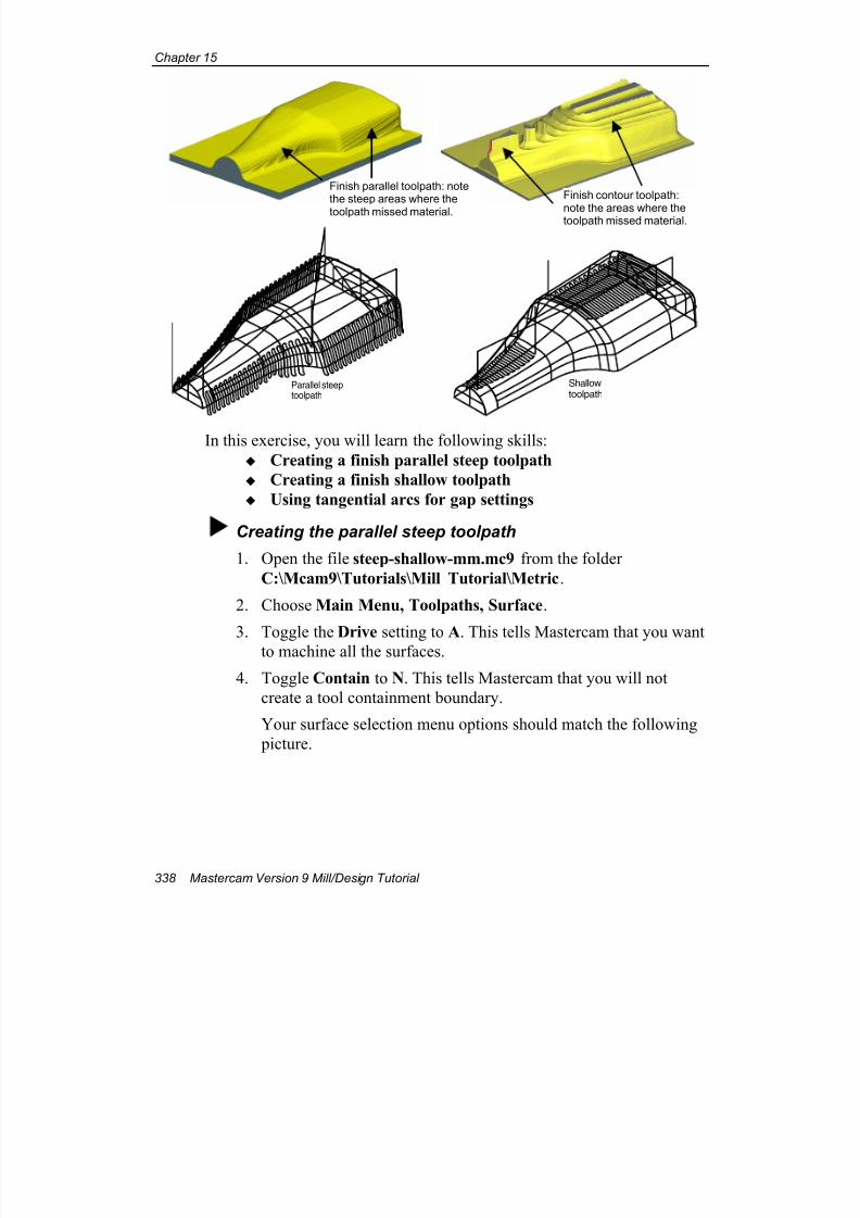
7/18/2019 V9 Mill-Design Tutorial (metric).pdf
http://slidepdf.com/reader/full/v9-mill-design-tutorial-metricpdf 350/453
Chapter 15
338 Mastercam Version 9 Mill/Design Tutorial
Parallel steeptoolpath
Shallowtoolpath
In this exercise, you will learn the following skills:
Creating a finish parallel steep toolpath
Creating a finish shallow toolpath
Using tangential arcs for gap settings
Creating the parallel steep toolpath
1. Open the file steep-shallow-mm.mc9 from the folder
C:\Mcam9\Tutorials\Mill Tutorial\Metric.
2. Choose Main Menu, Toolpaths, Surface.
3. Toggle the Drive setting to A. This tells Mastercam that you wantto machine all the surfaces.
4. Toggle Contain to N. This tells Mastercam that you will not
create a tool containment boundary.
Your surface selection menu options should match the following
picture.
Finish parallel toolpath: notethe steep areas where the
toolpath missed material.
Finish contour toolpath:
note the areas where thetoolpath missed material.
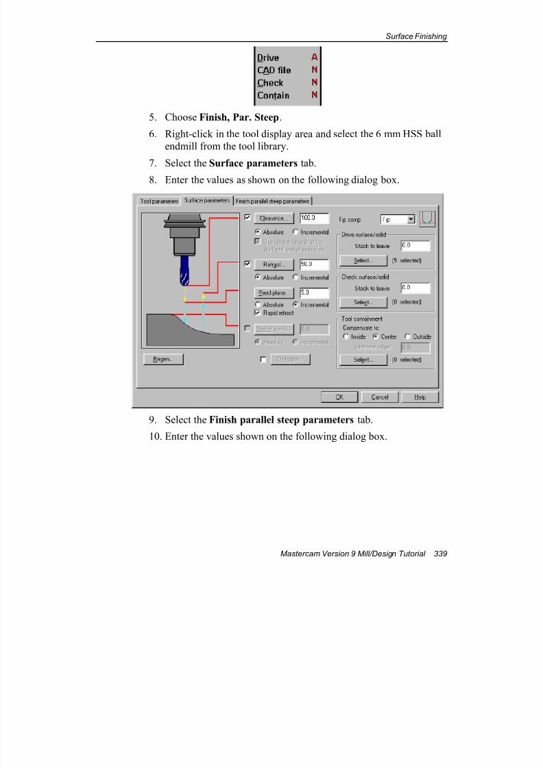
7/18/2019 V9 Mill-Design Tutorial (metric).pdf
http://slidepdf.com/reader/full/v9-mill-design-tutorial-metricpdf 351/453
Surface Finishing
Mastercam Version 9 Mill/Design Tutorial 339
5. Choose Finish, Par. Steep.
6. Right-click in the tool display area and select the 6 mm HSS ballendmill from the tool library.
7. Select the Surface parameters tab.
8. Enter the values as shown on the following dialog box.
9. Select the Finish parallel steep parameters tab.
10. Enter the values shown on the following dialog box.
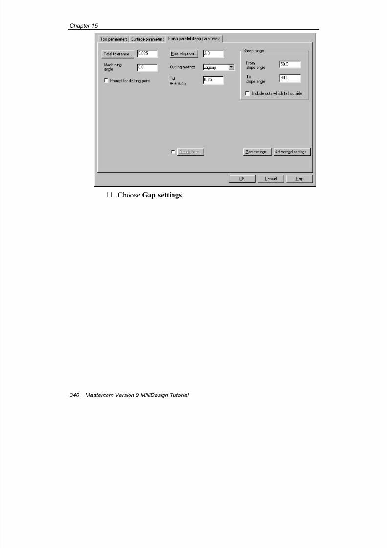
7/18/2019 V9 Mill-Design Tutorial (metric).pdf
http://slidepdf.com/reader/full/v9-mill-design-tutorial-metricpdf 352/453
Chapter 15
340 Mastercam Version 9 Mill/Design Tutorial
11. Choose Gap settings.
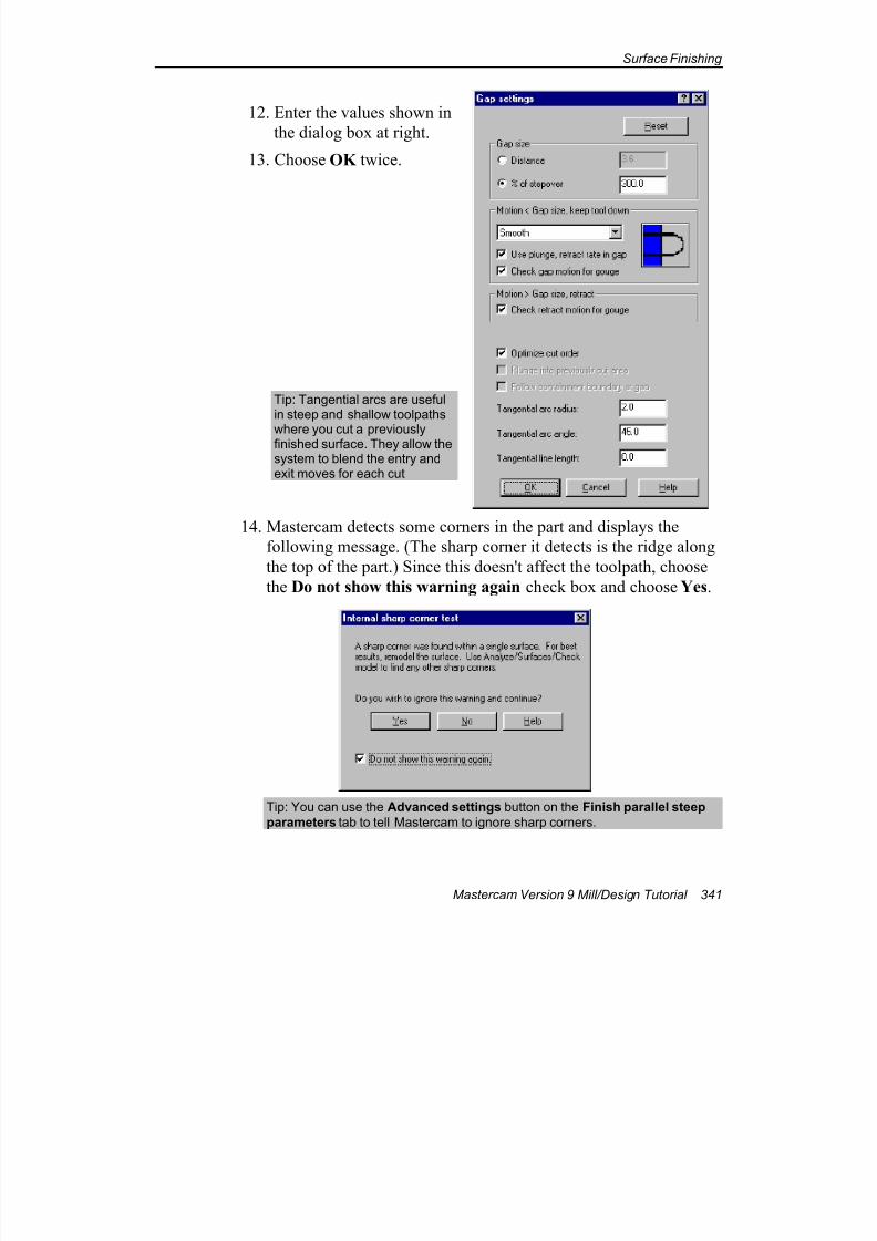
7/18/2019 V9 Mill-Design Tutorial (metric).pdf
http://slidepdf.com/reader/full/v9-mill-design-tutorial-metricpdf 353/453
Surface Finishing
Mastercam Version 9 Mill/Design Tutorial 341
12. Enter the values shown in
the dialog box at right.
13. Choose OK twice.
Tip: Tangential arcs are usefulin steep and shallow toolpaths
where you cut a previouslyfinished surface. They allow thesystem to blend the entry andexit moves for each cut
14. Mastercam detects some corners in the part and displays the
following message. (The sharp corner it detects is the ridge along
the top of the part.) Since this doesn't affect the toolpath, choose
the Do not show this warning again check box and choose Yes.
Tip: You can use the Advanced settings button on the Finish parallel steep
parameters tab to tell Mastercam to ignore sharp corners.
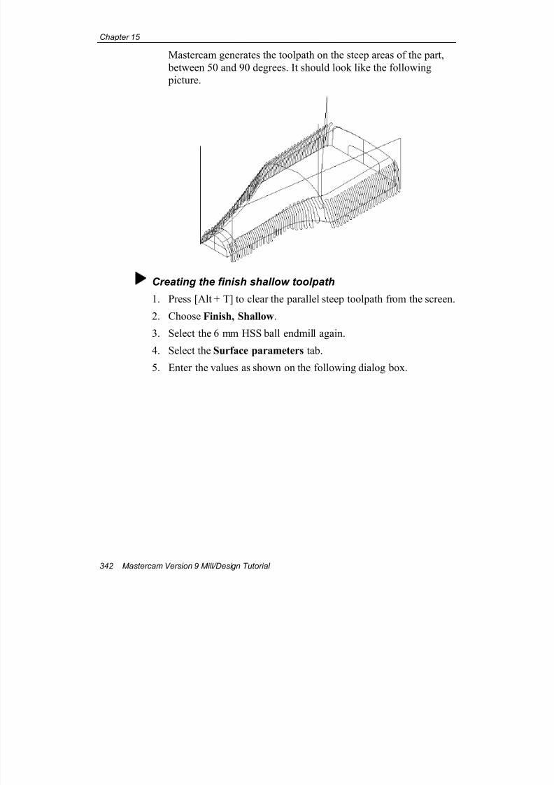
7/18/2019 V9 Mill-Design Tutorial (metric).pdf
http://slidepdf.com/reader/full/v9-mill-design-tutorial-metricpdf 354/453
Chapter 15
342 Mastercam Version 9 Mill/Design Tutorial
Mastercam generates the toolpath on the steep areas of the part,
between 50 and 90 degrees. It should look like the following
picture.
Creating the finish shallow toolpath
1. Press [Alt + T] to clear the parallel steep toolpath from the screen.
2. Choose Finish, Shallow.
3. Select the 6 mm HSS ball endmill again.
4. Select the Surface parameters tab.
5. Enter the values as shown on the following dialog box.
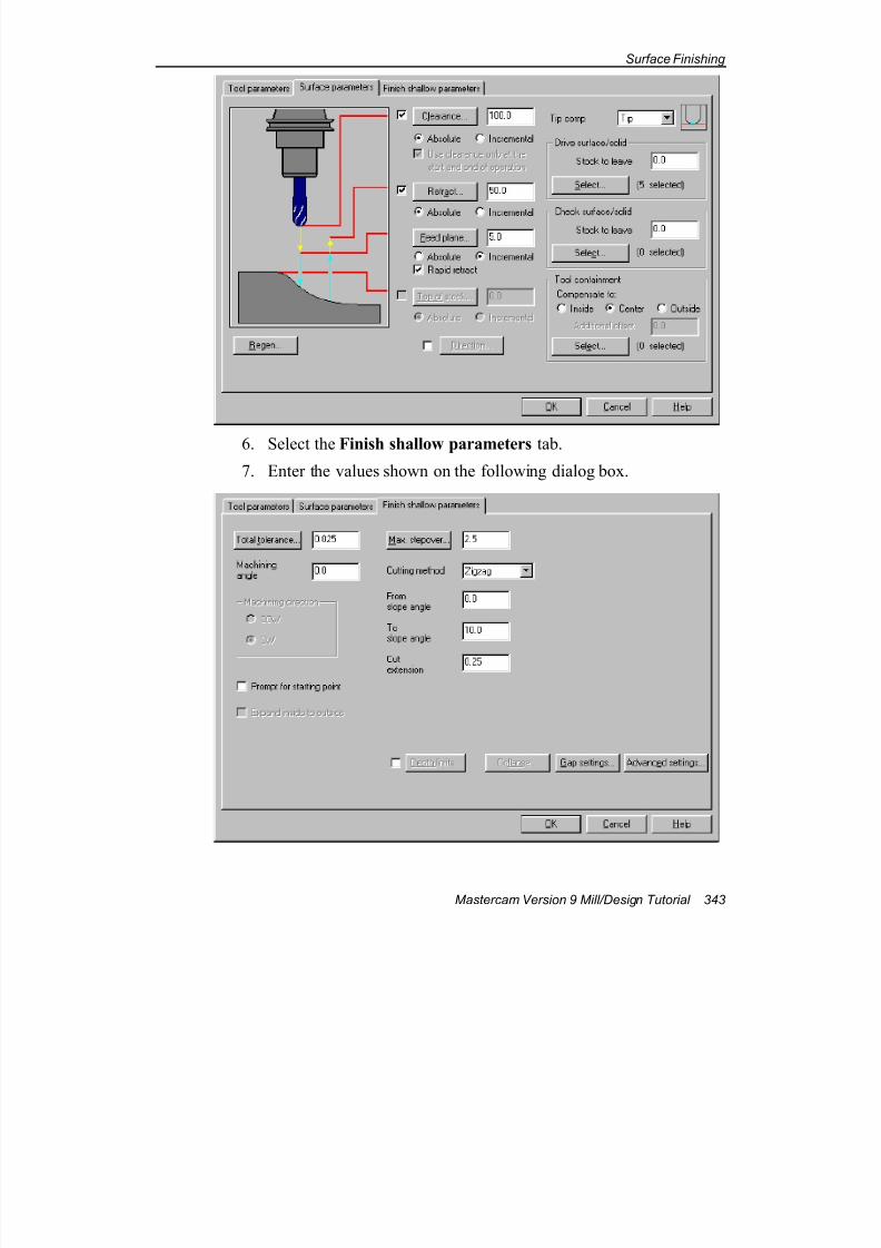
7/18/2019 V9 Mill-Design Tutorial (metric).pdf
http://slidepdf.com/reader/full/v9-mill-design-tutorial-metricpdf 355/453
Surface Finishing
Mastercam Version 9 Mill/Design Tutorial 343
6. Select the Finish shallow parameters tab.
7. Enter the values shown on the following dialog box.
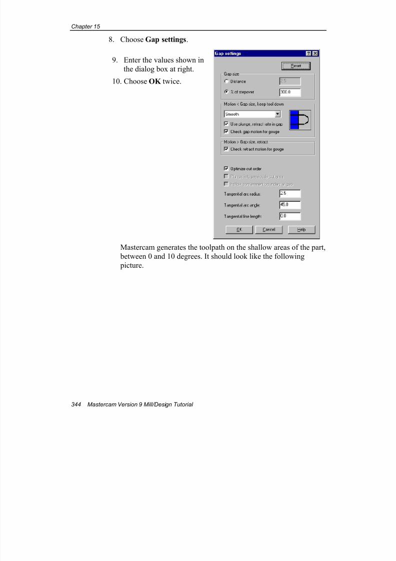
7/18/2019 V9 Mill-Design Tutorial (metric).pdf
http://slidepdf.com/reader/full/v9-mill-design-tutorial-metricpdf 356/453
Chapter 15
344 Mastercam Version 9 Mill/Design Tutorial
8. Choose Gap settings.
9. Enter the values shown in
the dialog box at right.
10. Choose OK twice.
Mastercam generates the toolpath on the shallow areas of the part,
between 0 and 10 degrees. It should look like the following
picture.
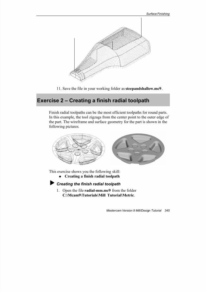
7/18/2019 V9 Mill-Design Tutorial (metric).pdf
http://slidepdf.com/reader/full/v9-mill-design-tutorial-metricpdf 357/453
Surface Finishing
Mastercam Version 9 Mill/Design Tutorial 345
11. Save the file in your working folder as steepandshallow.mc9.
Exercise 2 – Creating a finish radial toolpath
Finish radial toolpaths can be the most efficient toolpaths for round parts.
In this example, the tool zigzags from the center point to the outer edge of
the part. The wireframe and surface geometry for the part is shown in the
following pictures.
This exercise shows you the following skill:
Creating a finish radial toolpath
Creating the finish radial toolpath
1. Open the file radial-mm.mc9 from the folder
C:\Mcam9\Tutorials\Mill Tutorial\Metric.
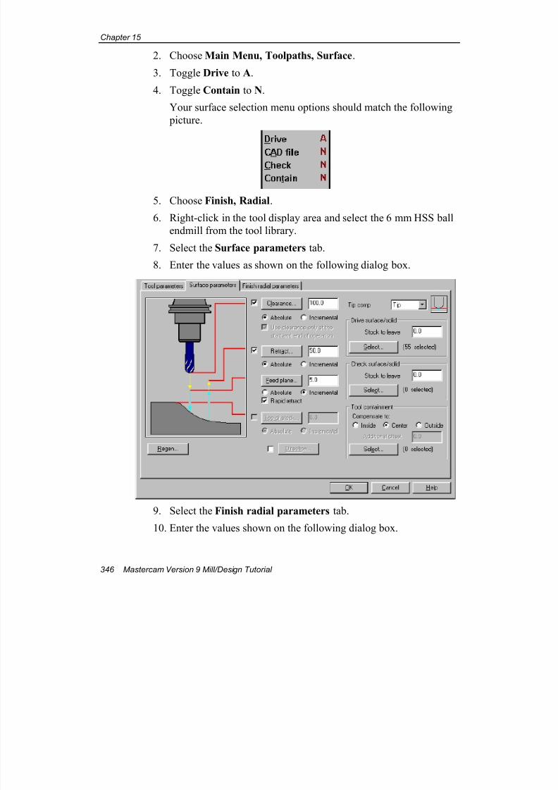
7/18/2019 V9 Mill-Design Tutorial (metric).pdf
http://slidepdf.com/reader/full/v9-mill-design-tutorial-metricpdf 358/453
Chapter 15
346 Mastercam Version 9 Mill/Design Tutorial
2. Choose Main Menu, Toolpaths, Surface.
3. Toggle Drive to A.
4. Toggle Contain to N.
Your surface selection menu options should match the following
picture.
5. Choose Finish, Radial.
6. Right-click in the tool display area and select the 6 mm HSS ball
endmill from the tool library.
7. Select the Surface parameters tab.
8. Enter the values as shown on the following dialog box.
9. Select the Finish radial parameters tab.
10. Enter the values shown on the following dialog box.
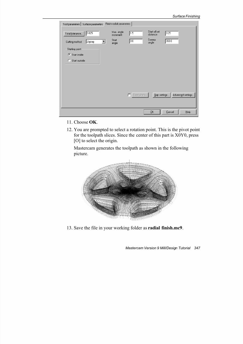
7/18/2019 V9 Mill-Design Tutorial (metric).pdf
http://slidepdf.com/reader/full/v9-mill-design-tutorial-metricpdf 359/453
Surface Finishing
Mastercam Version 9 Mill/Design Tutorial 347
11. Choose OK .
12. You are prompted to select a rotation point. This is the pivot point
for the toolpath slices. Since the center of this part is X0Y0, press
[O] to select the origin.
Mastercam generates the toolpath as shown in the following
picture.
13. Save the file in your working folder as radial finish.mc9.
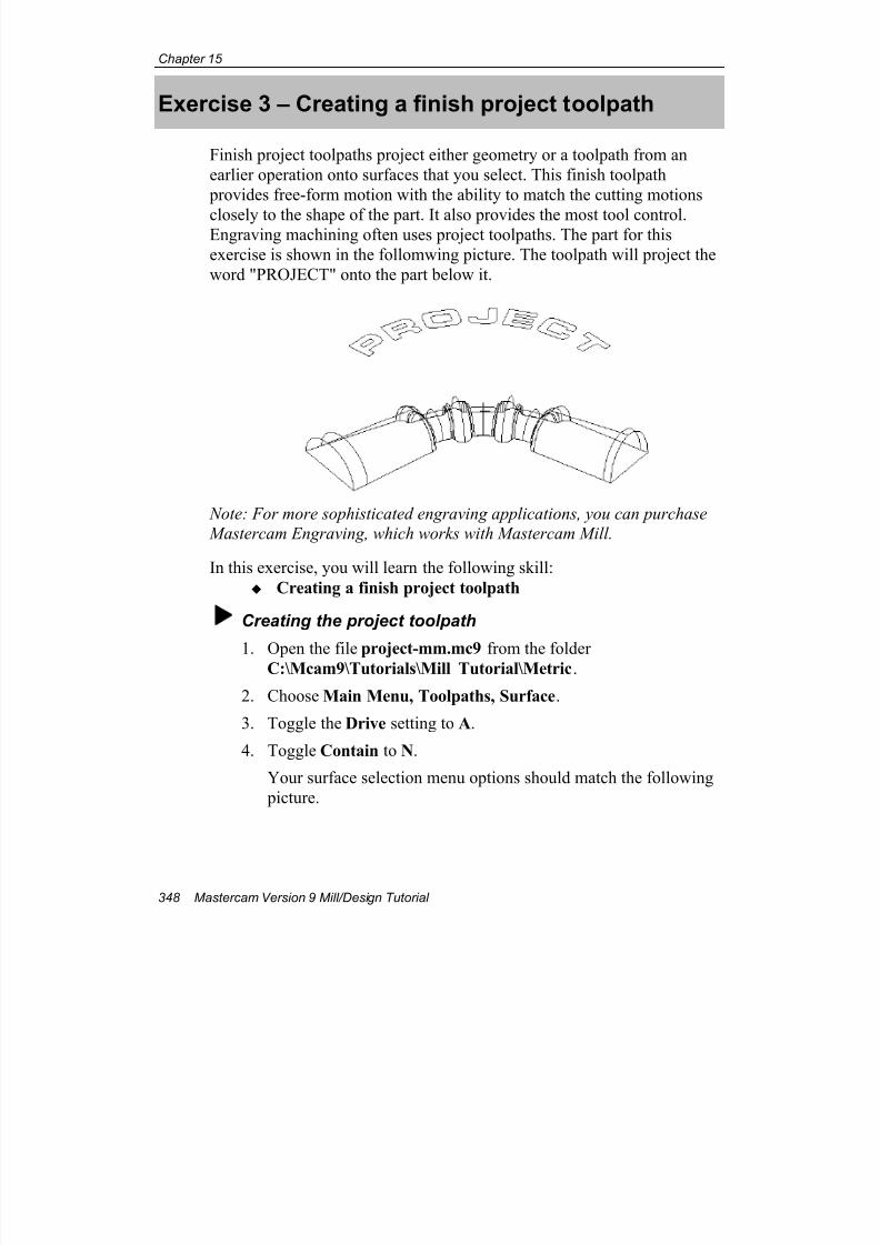
7/18/2019 V9 Mill-Design Tutorial (metric).pdf
http://slidepdf.com/reader/full/v9-mill-design-tutorial-metricpdf 360/453
Chapter 15
348 Mastercam Version 9 Mill/Design Tutorial
Exercise 3 – Creating a finish project toolpath
Finish project toolpaths project either geometry or a toolpath from an
earlier operation onto surfaces that you select. This finish toolpath
provides free-form motion with the ability to match the cutting motions
closely to the shape of the part. It also provides the most tool control.Engraving machining often uses project toolpaths. The part for this
exercise is shown in the follomwing picture. The toolpath will project the
word "PROJECT" onto the part below it.
Note: For more sophisticated engraving applications, you can purchase
Mastercam Engraving, which works with Mastercam Mill.
In this exercise, you will learn the following skill:
Creating a finish project toolpath
Creating the project toolpath
1. Open the file project-mm.mc9 from the folderC:\Mcam9\Tutorials\Mill Tutorial\Metric.
2. Choose Main Menu, Toolpaths, Surface.
3. Toggle the Drive setting to A.
4. Toggle Contain to N.
Your surface selection menu options should match the following
picture.
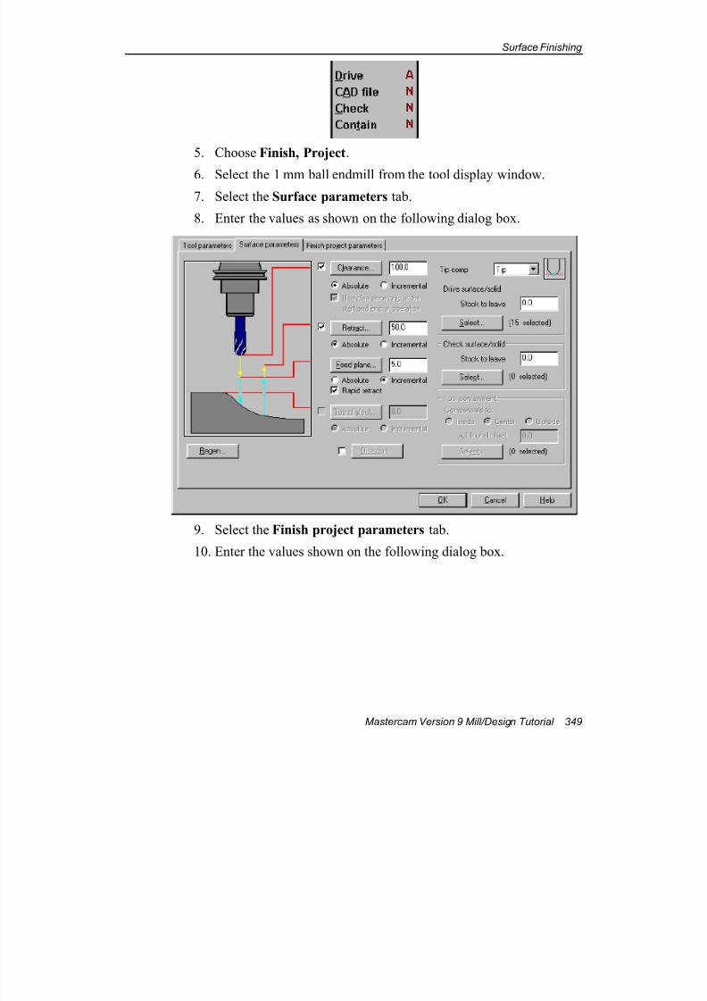
7/18/2019 V9 Mill-Design Tutorial (metric).pdf
http://slidepdf.com/reader/full/v9-mill-design-tutorial-metricpdf 361/453
Surface Finishing
Mastercam Version 9 Mill/Design Tutorial 349
5. Choose Finish, Project.
6. Select the 1 mm ball endmill from the tool display window.
7. Select the Surface parameters tab.
8. Enter the values as shown on the following dialog box.
9. Select the Finish project parameters tab.
10. Enter the values shown on the following dialog box.
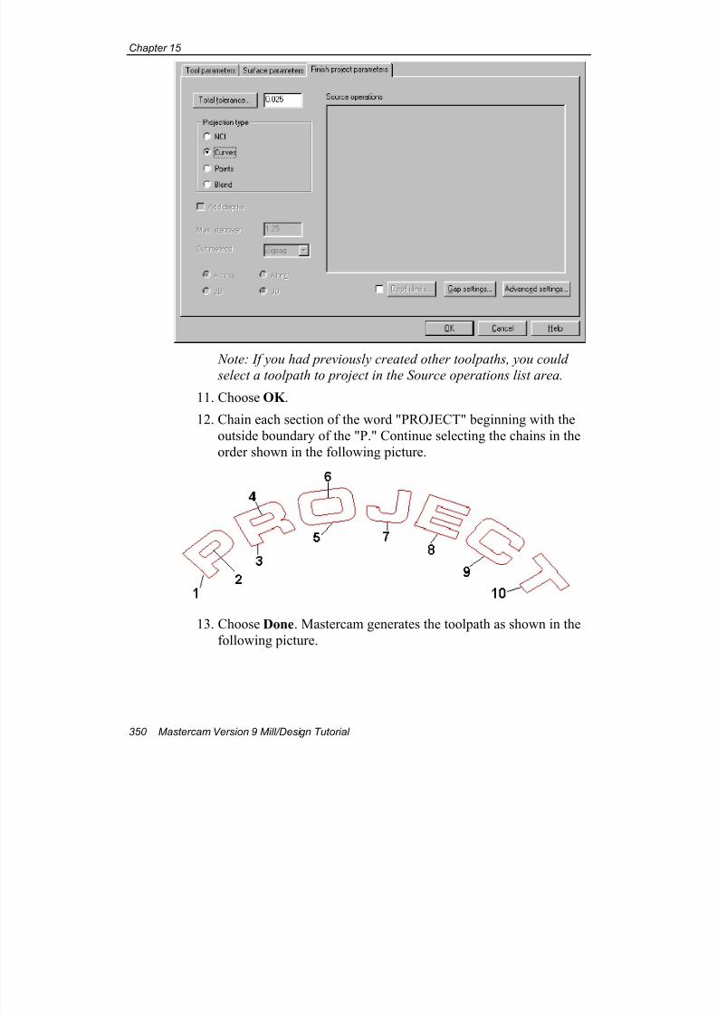
7/18/2019 V9 Mill-Design Tutorial (metric).pdf
http://slidepdf.com/reader/full/v9-mill-design-tutorial-metricpdf 362/453
Chapter 15
350 Mastercam Version 9 Mill/Design Tutorial
Note: If you had previously created other toolpaths, you could select a toolpath to project in the Source operations list area.
11. Choose OK .
12. Chain each section of the word "PROJECT" beginning with the
outside boundary of the "P." Continue selecting the chains in the
order shown in the following picture.
13. Choose Done. Mastercam generates the toolpath as shown in the
following picture.
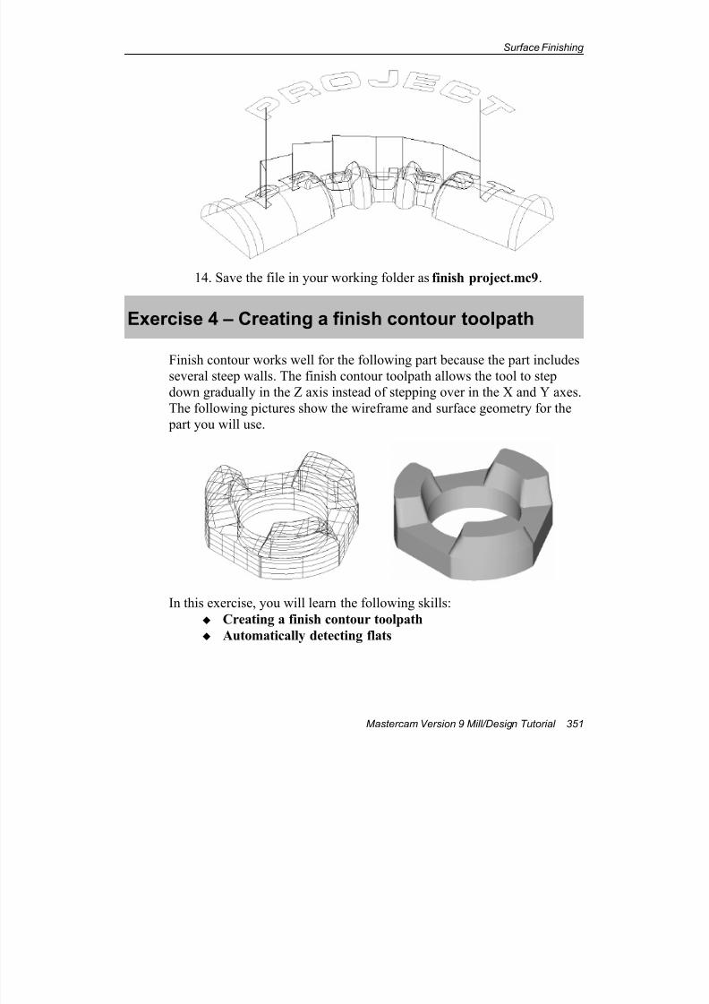
7/18/2019 V9 Mill-Design Tutorial (metric).pdf
http://slidepdf.com/reader/full/v9-mill-design-tutorial-metricpdf 363/453
Surface Finishing
Mastercam Version 9 Mill/Design Tutorial 351
14. Save the file in your working folder as finish project.mc9.
Exercise 4 – Creating a finish contour toolpath
Finish contour works well for the following part because the part includes
several steep walls. The finish contour toolpath allows the tool to step
down gradually in the Z axis instead of stepping over in the X and Y axes.
The following pictures show the wireframe and surface geometry for the
part you will use.
In this exercise, you will learn the following skills:
Creating a finish contour toolpath
Automatically detecting flats

7/18/2019 V9 Mill-Design Tutorial (metric).pdf
http://slidepdf.com/reader/full/v9-mill-design-tutorial-metricpdf 364/453
Chapter 15
352 Mastercam Version 9 Mill/Design Tutorial
Creating the finish contour toolpath
1. Open the file finish contour-mm.mc9 from the folder
C:\Mcam9\Tutorials\Mill Tutorial\Metric.
2. Choose Main Menu, Toolpaths, Surface.
3. Toggle the Drive setting to A.
4. Toggle Contain to N.
Your surface selection menu options should match the following
picture.
5. Choose Finish, Contour.
6. Right-click in the tool display area and select the 16 mm HSS bullnose endmill with 3 mm radius from the tool library.
7. Select the Surface parameters tab.
8. Enter the values as shown on the following dialog box.
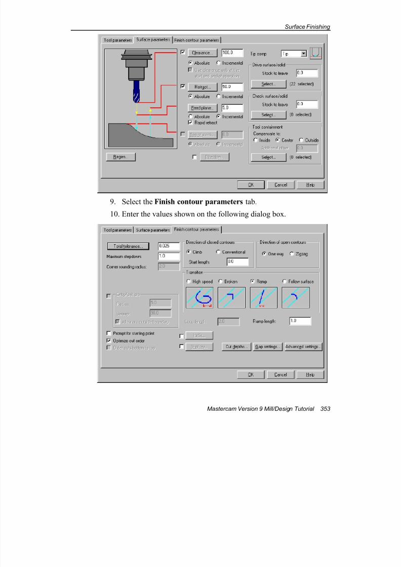
7/18/2019 V9 Mill-Design Tutorial (metric).pdf
http://slidepdf.com/reader/full/v9-mill-design-tutorial-metricpdf 365/453
Surface Finishing
Mastercam Version 9 Mill/Design Tutorial 353
9. Select the Finish contour parameters tab.
10. Enter the values shown on the following dialog box.
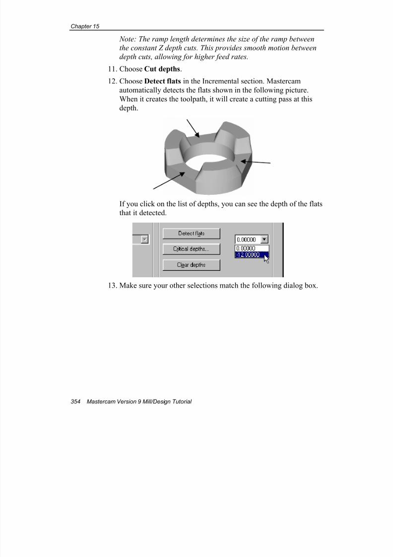
7/18/2019 V9 Mill-Design Tutorial (metric).pdf
http://slidepdf.com/reader/full/v9-mill-design-tutorial-metricpdf 366/453
Chapter 15
354 Mastercam Version 9 Mill/Design Tutorial
Note: The ramp length determines the size of the ramp between
the constant Z depth cuts. This provides smooth motion between
depth cuts, allowing for higher feed rates.
11. Choose Cut depths.
12. Choose Detect flats in the Incremental section. Mastercam
automatically detects the flats shown in the following picture.
When it creates the toolpath, it will create a cutting pass at thisdepth.
If you click on the list of depths, you can see the depth of the flats
that it detected.
13. Make sure your other selections match the following dialog box.
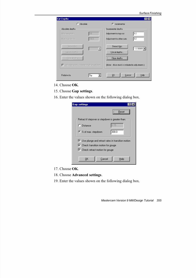
7/18/2019 V9 Mill-Design Tutorial (metric).pdf
http://slidepdf.com/reader/full/v9-mill-design-tutorial-metricpdf 367/453
Surface Finishing
Mastercam Version 9 Mill/Design Tutorial 355
14. Choose OK .
15. Choose Gap settings.
16. Enter the values shown on the following dialog box.
17. Choose OK .
18. Choose Advanced settings.
19. Enter the values shown on the following dialog box.
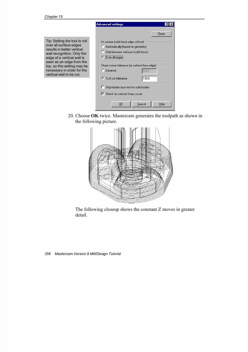
7/18/2019 V9 Mill-Design Tutorial (metric).pdf
http://slidepdf.com/reader/full/v9-mill-design-tutorial-metricpdf 368/453
Chapter 15
356 Mastercam Version 9 Mill/Design Tutorial
20. Choose OK twice. Mastercam generates the toolpath as shown in
the following picture.
The following closeup shows the constant Z moves in greater
detail.
Tip: Setting the tool to rollover all surface edgesresults in better verticalwall recognition. Only theedge of a vertical wall is
seen as an edge from thetop, so this setting may benecessary in order for thevertical wall to be cut.
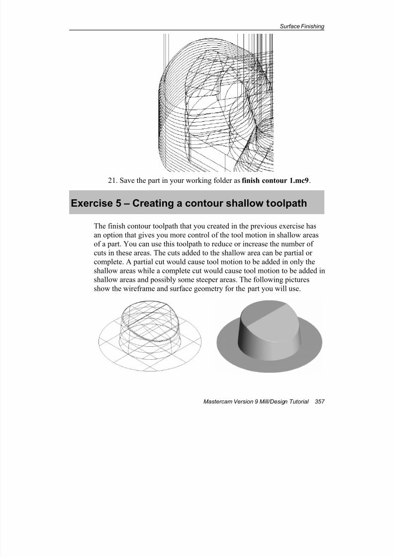
7/18/2019 V9 Mill-Design Tutorial (metric).pdf
http://slidepdf.com/reader/full/v9-mill-design-tutorial-metricpdf 369/453
Surface Finishing
Mastercam Version 9 Mill/Design Tutorial 357
21. Save the part in your working folder as finish contour 1.mc9.
Exercise 5 – Creating a contour shallow toolpath
The finish contour toolpath that you created in the previous exercise has
an option that gives you more control of the tool motion in shallow areas
of a part. You can use this toolpath to reduce or increase the number of
cuts in these areas. The cuts added to the shallow area can be partial or
complete. A partial cut would cause tool motion to be added in only the
shallow areas while a complete cut would cause tool motion to be added in
shallow areas and possibly some steeper areas. The following pictures
show the wireframe and surface geometry for the part you will use.

7/18/2019 V9 Mill-Design Tutorial (metric).pdf
http://slidepdf.com/reader/full/v9-mill-design-tutorial-metricpdf 370/453
Chapter 15
358 Mastercam Version 9 Mill/Design Tutorial
In this exercise, you will learn the following skill:
Optimizing a finish contour toolpath for a shallow part
Creating the contour shallow toolpath
1. Open the file add cuts-mm.mc9 from the folder
C:\Mcam9\Tutorials\Mill Tutorial\Metric.
2. Choose Main Menu, Toolpaths, Surface.3. Toggle the Drive setting to A.
4. Toggle Contain to N.
Your surface selection menu options should match the following
picture.
5. Choose Finish, Contour.
6. Right-click in the tool display area and select the 18 mm HSS flat
endmill from the tool library.
7. Select the Surface parameters tab.
8. Enter the values as shown on the following dialog box.
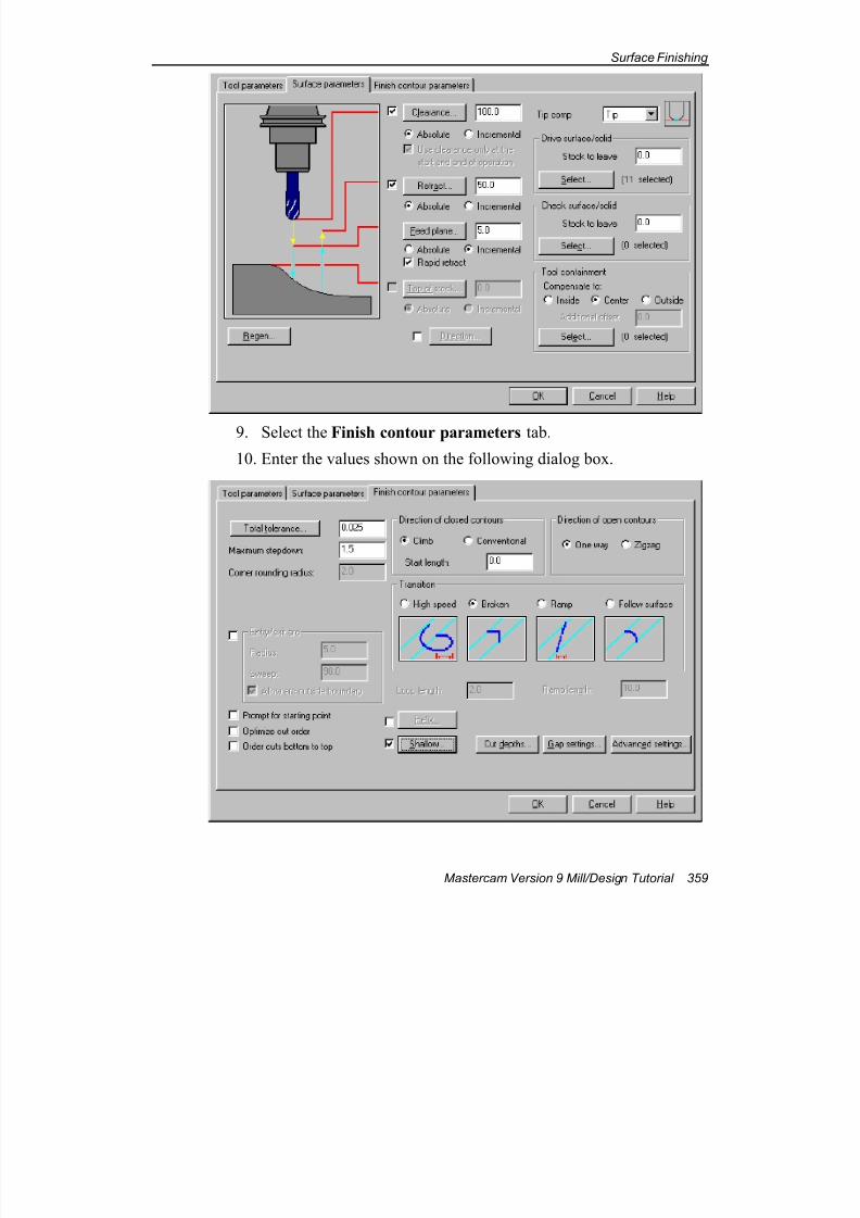
7/18/2019 V9 Mill-Design Tutorial (metric).pdf
http://slidepdf.com/reader/full/v9-mill-design-tutorial-metricpdf 371/453
Surface Finishing
Mastercam Version 9 Mill/Design Tutorial 359
9. Select the Finish contour parameters tab.
10. Enter the values shown on the following dialog box.
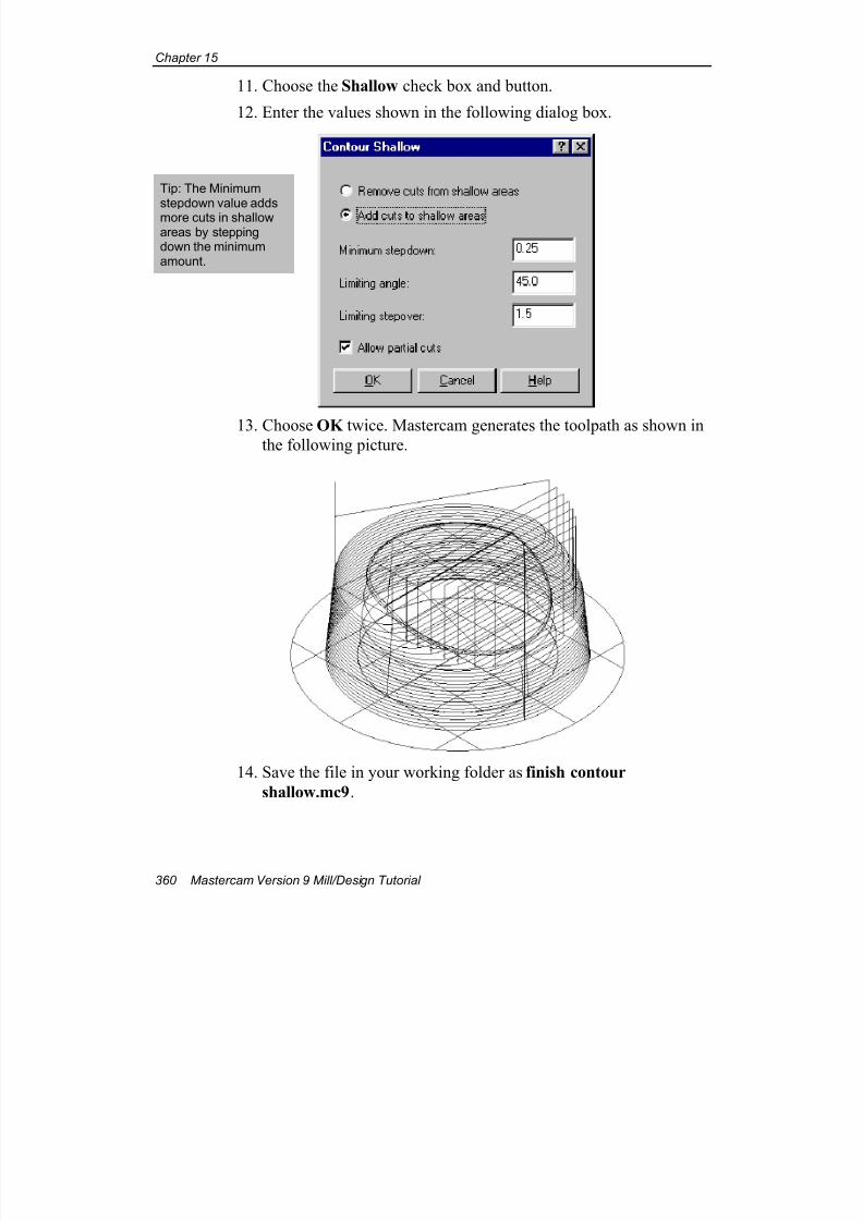
7/18/2019 V9 Mill-Design Tutorial (metric).pdf
http://slidepdf.com/reader/full/v9-mill-design-tutorial-metricpdf 372/453
Chapter 15
360 Mastercam Version 9 Mill/Design Tutorial
11. Choose the Shallow check box and button.
12. Enter the values shown in the following dialog box.
13. Choose OK twice. Mastercam generates the toolpath as shown inthe following picture.
14. Save the file in your working folder as finish contour
shallow.mc9.
Tip: The Minimumstepdown value adds
more cuts in shallowareas by steppingdown the minimumamount.
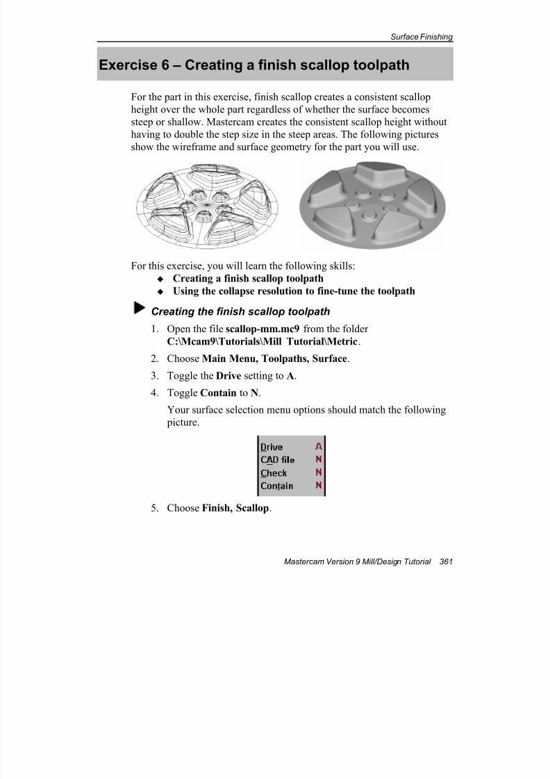
7/18/2019 V9 Mill-Design Tutorial (metric).pdf
http://slidepdf.com/reader/full/v9-mill-design-tutorial-metricpdf 373/453
Surface Finishing
Mastercam Version 9 Mill/Design Tutorial 361
Exercise 6 – Creating a finish scallop toolpath
For the part in this exercise, finish scallop creates a consistent scallop
height over the whole part regardless of whether the surface becomes
steep or shallow. Mastercam creates the consistent scallop height without
having to double the step size in the steep areas. The following picturesshow the wireframe and surface geometry for the part you will use.
For this exercise, you will learn the following skills:
Creating a finish scallop toolpath
Using the collapse resolution to fine-tune the toolpath
Creating the finish scallop toolpath
1. Open the file scallop-mm.mc9 from the folder
C:\Mcam9\Tutorials\Mill Tutorial\Metric.
2. Choose Main Menu, Toolpaths, Surface.
3. Toggle the Drive setting to A.
4. Toggle Contain to N.
Your surface selection menu options should match the following picture.
5. Choose Finish, Scallop.
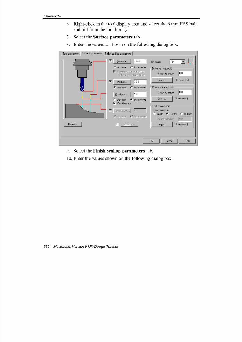
7/18/2019 V9 Mill-Design Tutorial (metric).pdf
http://slidepdf.com/reader/full/v9-mill-design-tutorial-metricpdf 374/453
Chapter 15
362 Mastercam Version 9 Mill/Design Tutorial
6. Right-click in the tool display area and select the 6 mm HSS ball
endmill from the tool library.
7. Select the Surface parameters tab.
8. Enter the values as shown on the following dialog box.
9. Select the Finish scallop parameters tab.
10. Enter the values shown on the following dialog box.
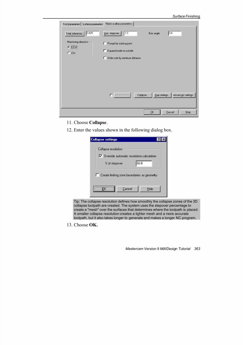
7/18/2019 V9 Mill-Design Tutorial (metric).pdf
http://slidepdf.com/reader/full/v9-mill-design-tutorial-metricpdf 375/453
Surface Finishing
Mastercam Version 9 Mill/Design Tutorial 363
11. Choose Collapse.
12. Enter the values shown in the following dialog box.
Tip: The collapse resolution defines how smoothly the collapse zones of the 3Dcollapse toolpath are created. The system uses the stepover percentage tocreate a "mesh" over the surfaces that determines where the toolpath is placed.
A smaller collapse resolution creates a tighter mesh and a more accuratetoolpath, but it also takes longer to generate and makes a longer NC program.
13. Choose OK.
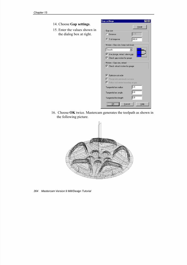
7/18/2019 V9 Mill-Design Tutorial (metric).pdf
http://slidepdf.com/reader/full/v9-mill-design-tutorial-metricpdf 376/453
Chapter 15
364 Mastercam Version 9 Mill/Design Tutorial
14. Choose Gap settings.
15. Enter the values shown in
the dialog box at right.
16. Choose OK twice. Mastercam generates the toolpath as shown in
the following picture.
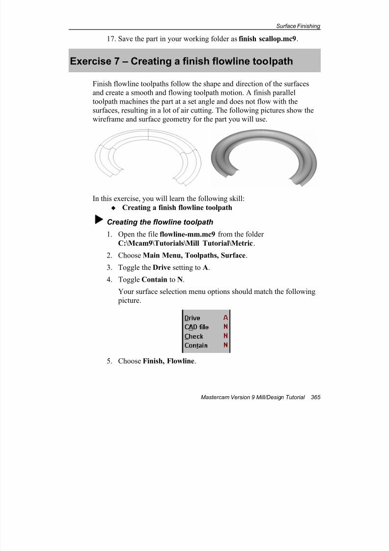
7/18/2019 V9 Mill-Design Tutorial (metric).pdf
http://slidepdf.com/reader/full/v9-mill-design-tutorial-metricpdf 377/453
Surface Finishing
Mastercam Version 9 Mill/Design Tutorial 365
17. Save the part in your working folder as finish scallop.mc9.
Exercise 7 – Creating a finish flowline toolpath
Finish flowline toolpaths follow the shape and direction of the surfaces
and create a smooth and flowing toolpath motion. A finish paralleltoolpath machines the part at a set angle and does not flow with the
surfaces, resulting in a lot of air cutting. The following pictures show the
wireframe and surface geometry for the part you will use.
In this exercise, you will learn the following skill:
Creating a finish flowline toolpath
Creating the flowline toolpath
1. Open the file flowline-mm.mc9 from the folder
C:\Mcam9\Tutorials\Mill Tutorial\Metric.
2. Choose Main Menu, Toolpaths, Surface.
3. Toggle the Drive setting to A.
4. Toggle Contain to N.
Your surface selection menu options should match the following picture.
5. Choose Finish, Flowline.
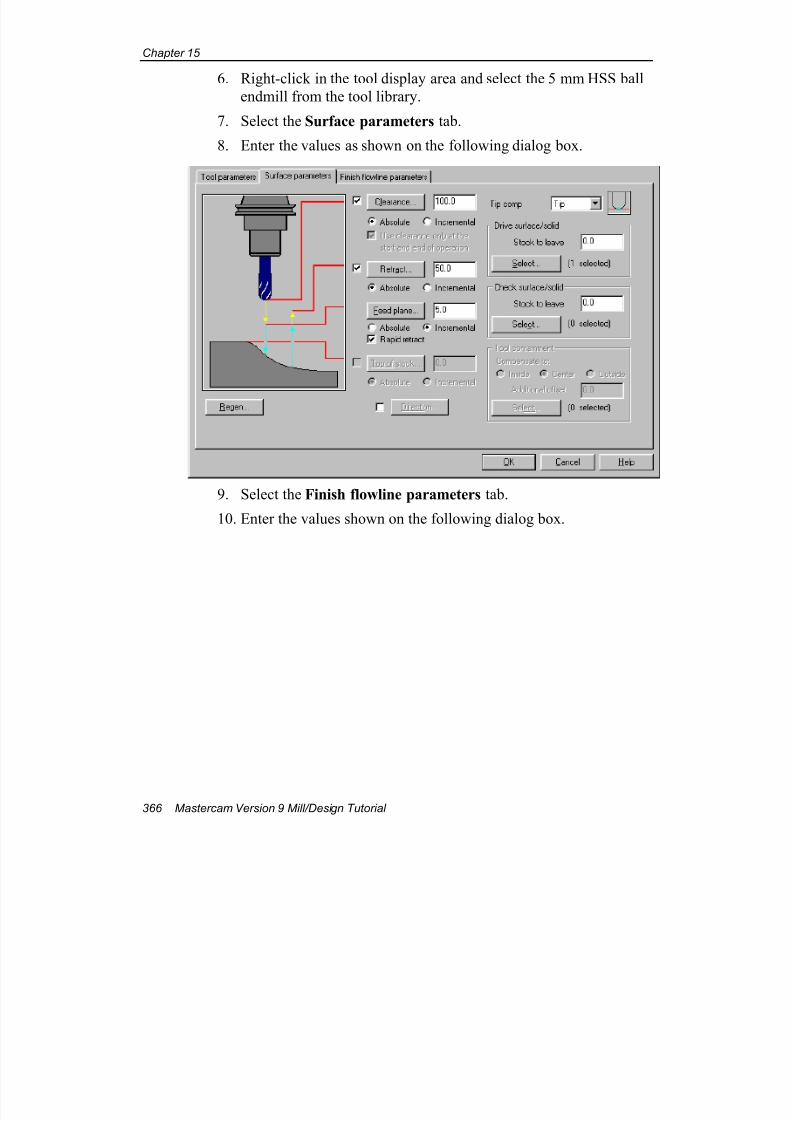
7/18/2019 V9 Mill-Design Tutorial (metric).pdf
http://slidepdf.com/reader/full/v9-mill-design-tutorial-metricpdf 378/453
Chapter 15
366 Mastercam Version 9 Mill/Design Tutorial
6. Right-click in the tool display area and select the 5 mm HSS ball
endmill from the tool library.
7. Select the Surface parameters tab.
8. Enter the values as shown on the following dialog box.
9. Select the Finish flowline parameters tab.
10. Enter the values shown on the following dialog box.
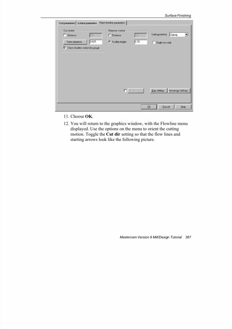
7/18/2019 V9 Mill-Design Tutorial (metric).pdf
http://slidepdf.com/reader/full/v9-mill-design-tutorial-metricpdf 379/453
Surface Finishing
Mastercam Version 9 Mill/Design Tutorial 367
11. Choose OK .
12. You will return to the graphics window, with the Flowline menu
displayed. Use the options on the menu to orient the cutting
motion. Toggle the Cut dir setting so that the flow lines and
starting arrows look like the following picture.
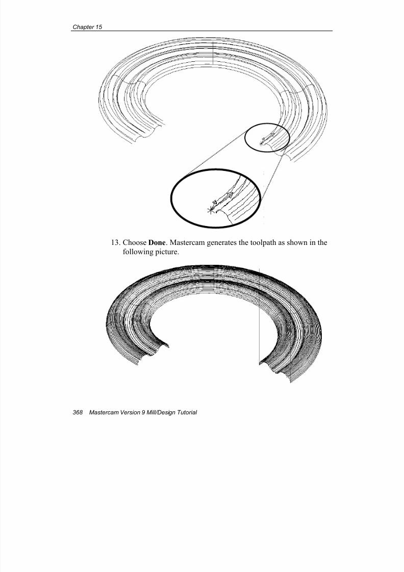
7/18/2019 V9 Mill-Design Tutorial (metric).pdf
http://slidepdf.com/reader/full/v9-mill-design-tutorial-metricpdf 380/453
Chapter 15
368 Mastercam Version 9 Mill/Design Tutorial
13. Choose Done. Mastercam generates the toolpath as shown in the
following picture.

7/18/2019 V9 Mill-Design Tutorial (metric).pdf
http://slidepdf.com/reader/full/v9-mill-design-tutorial-metricpdf 381/453
Surface Finishing
Mastercam Version 9 Mill/Design Tutorial 369
14. Save the file in your working folder as finish flowline.mc9.
In this chapter and the previous chapters, you have seen how Mastercam's
surface machining toolpaths give you many options for tailoring toolpaths
to your part geometry. The next chapter will show you how Mastercam
can use the multiaxis capabilities of your machine tool to produce even
more sophisticated surfacing toolpaths.

7/18/2019 V9 Mill-Design Tutorial (metric).pdf
http://slidepdf.com/reader/full/v9-mill-design-tutorial-metricpdf 382/453
Chapter 15
370 Mastercam Version 9 Mill/Design Tutorial
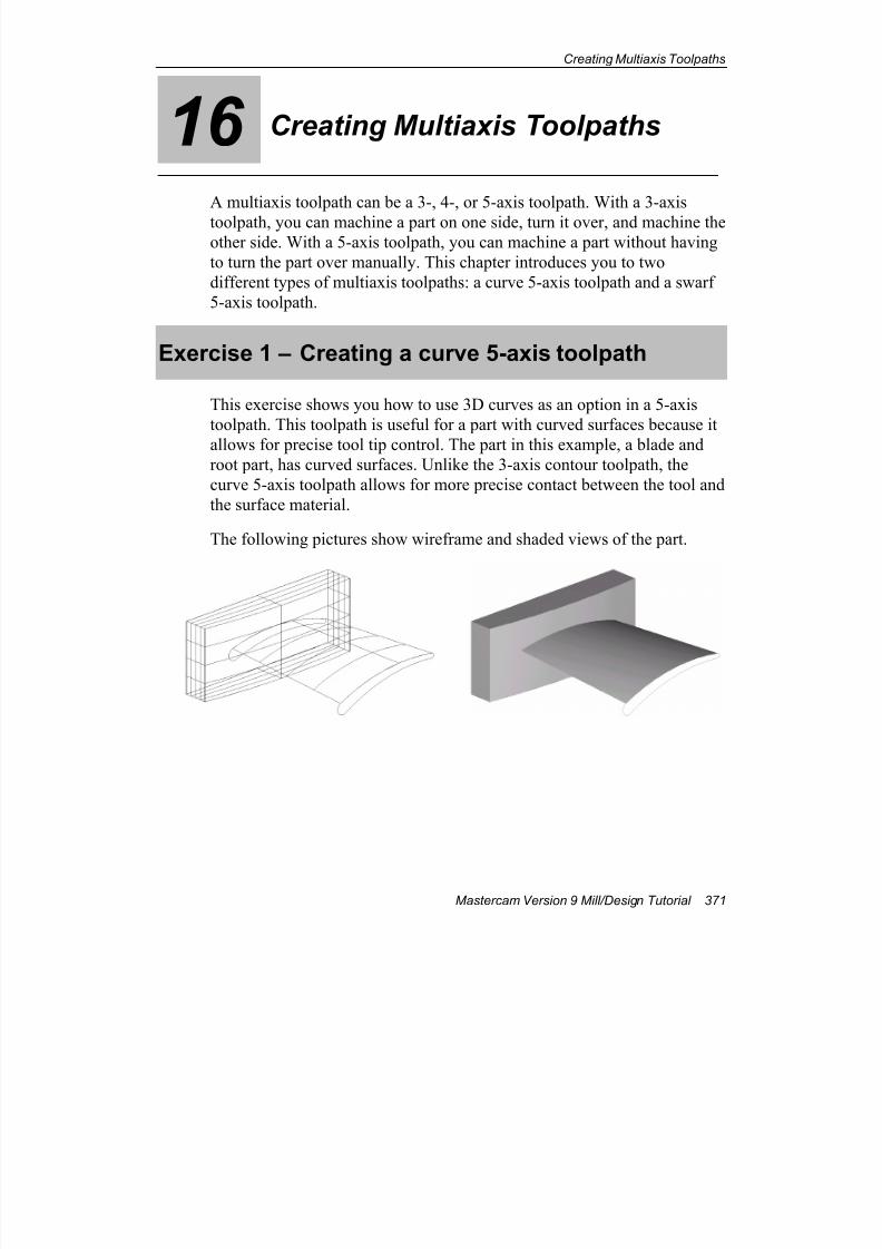
7/18/2019 V9 Mill-Design Tutorial (metric).pdf
http://slidepdf.com/reader/full/v9-mill-design-tutorial-metricpdf 383/453
Creating Multiaxis Toolpaths
Mastercam Version 9 Mill/Design Tutorial 371
16 Creating Multiaxis Toolpaths
A multiaxis toolpath can be a 3-, 4-, or 5-axis toolpath. With a 3-axis
toolpath, you can machine a part on one side, turn it over, and machine theother side. With a 5-axis toolpath, you can machine a part without having
to turn the part over manually. This chapter introduces you to two
different types of multiaxis toolpaths: a curve 5-axis toolpath and a swarf
5-axis toolpath.
Exercise 1 – Creating a curve 5-axis toolpath
This exercise shows you how to use 3D curves as an option in a 5-axis
toolpath. This toolpath is useful for a part with curved surfaces because it
allows for precise tool tip control. The part in this example, a blade and
root part, has curved surfaces. Unlike the 3-axis contour toolpath, the
curve 5-axis toolpath allows for more precise contact between the tool and
the surface material.
The following pictures show wireframe and shaded views of the part.
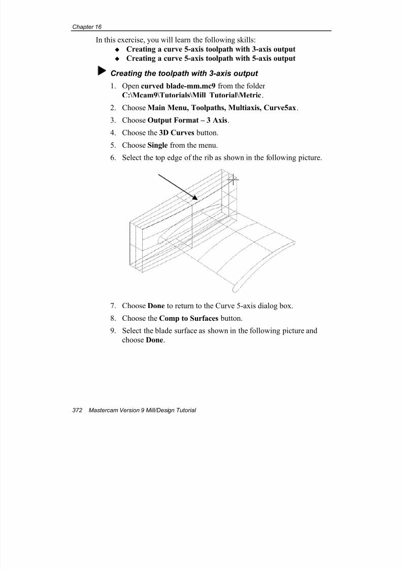
7/18/2019 V9 Mill-Design Tutorial (metric).pdf
http://slidepdf.com/reader/full/v9-mill-design-tutorial-metricpdf 384/453
Chapter 16
372 Mastercam Version 9 Mill/Design Tutorial
In this exercise, you will learn the following skills:
Creating a curve 5-axis toolpath with 3-axis output
Creating a curve 5-axis toolpath with 5-axis output
Creating the toolpath with 3-axis output
1. Open curved blade-mm.mc9 from the folder
C:\Mcam9\Tutorials\Mill Tutorial\Metric.
2. Choose Main Menu, Toolpaths, Multiaxis, Curve5ax.
3. Choose Output Format – 3 Axis.
4. Choose the 3D Curves button.
5. Choose Single from the menu.
6. Select the top edge of the rib as shown in the following picture.
7. Choose Done to return to the Curve 5-axis dialog box.
8. Choose the Comp to Surfaces button.
9. Select the blade surface as shown in the following picture and
choose Done.
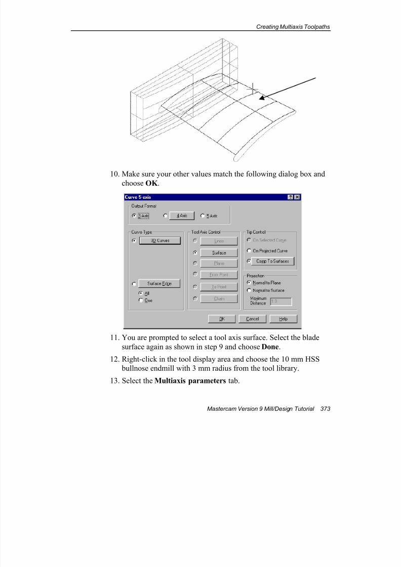
7/18/2019 V9 Mill-Design Tutorial (metric).pdf
http://slidepdf.com/reader/full/v9-mill-design-tutorial-metricpdf 385/453
Creating Multiaxis Toolpaths
Mastercam Version 9 Mill/Design Tutorial 373
10. Make sure your other values match the following dialog box and
choose OK .
11. You are prompted to select a tool axis surface. Select the blade
surface again as shown in step 9 and choose Done.
12. Right-click in the tool display area and choose the 10 mm HSS
bullnose endmill with 3 mm radius from the tool library.
13. Select the Multiaxis parameters tab.
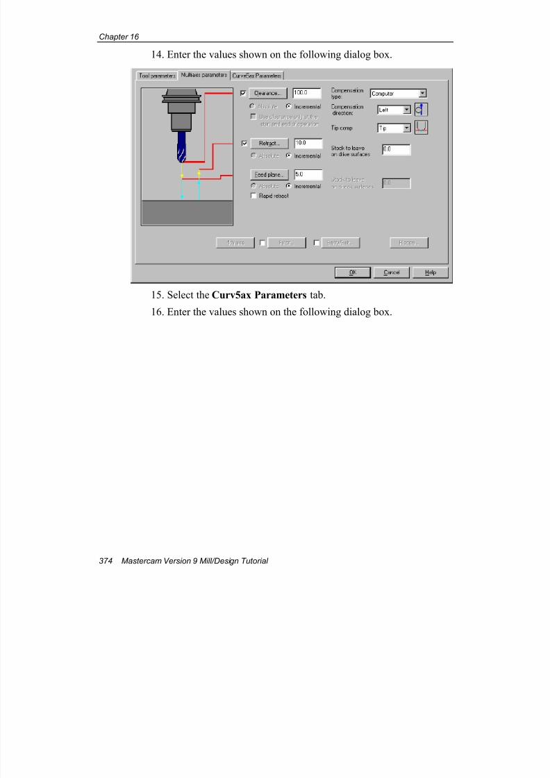
7/18/2019 V9 Mill-Design Tutorial (metric).pdf
http://slidepdf.com/reader/full/v9-mill-design-tutorial-metricpdf 386/453
Chapter 16
374 Mastercam Version 9 Mill/Design Tutorial
14. Enter the values shown on the following dialog box.
15. Select the Curv5ax Parameters tab.
16. Enter the values shown on the following dialog box.
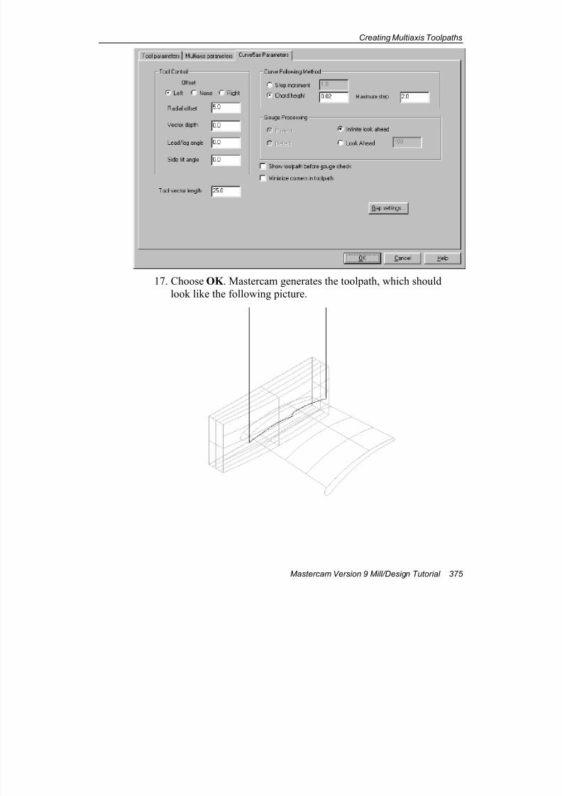
7/18/2019 V9 Mill-Design Tutorial (metric).pdf
http://slidepdf.com/reader/full/v9-mill-design-tutorial-metricpdf 387/453
Creating Multiaxis Toolpaths
Mastercam Version 9 Mill/Design Tutorial 375
17. Choose OK . Mastercam generates the toolpath, which shouldlook like the following picture.
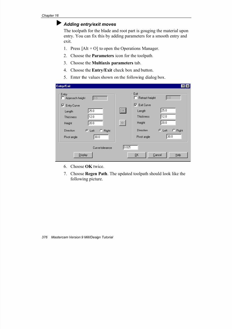
7/18/2019 V9 Mill-Design Tutorial (metric).pdf
http://slidepdf.com/reader/full/v9-mill-design-tutorial-metricpdf 388/453
Chapter 16
376 Mastercam Version 9 Mill/Design Tutorial
Adding entry/exit moves
The toolpath for the blade and root part is gouging the material upon
entry. You can fix this by adding parameters for a smooth entry and
exit.
1. Press [Alt + O] to open the Operations Manager.
2. Choose the Parameters icon for the toolpath.3. Choose the Multiaxis parameters tab.
4. Choose the Entry/Exit check box and button.
5. Enter the values shown on the following dialog box.
6. Choose OK twice.
7. Choose Regen Path. The updated toolpath should look like thefollowing picture.

7/18/2019 V9 Mill-Design Tutorial (metric).pdf
http://slidepdf.com/reader/full/v9-mill-design-tutorial-metricpdf 389/453
Creating Multiaxis Toolpaths
Mastercam Version 9 Mill/Design Tutorial 377
Note: This picture has been rotated with the Gview–Dynamic
function to show the entry/exit moves more clearly.
Changing the toolpath to 5-axis outputUnlike the 3-axis toolpath you just created, the 5-axis toolpath lets the
entire surface of the part control the orientation of the tool. Also, by
setting a lead/lag angle for the tool, the tool can lean forward or
backward for more effective cleanout.
1. If necessary, press [Alt + O] to return to the Operations Manager.
2. Choose the Geometry icon for the toolpath.
3. Change the Output Format to 5 Axis and choose OK .
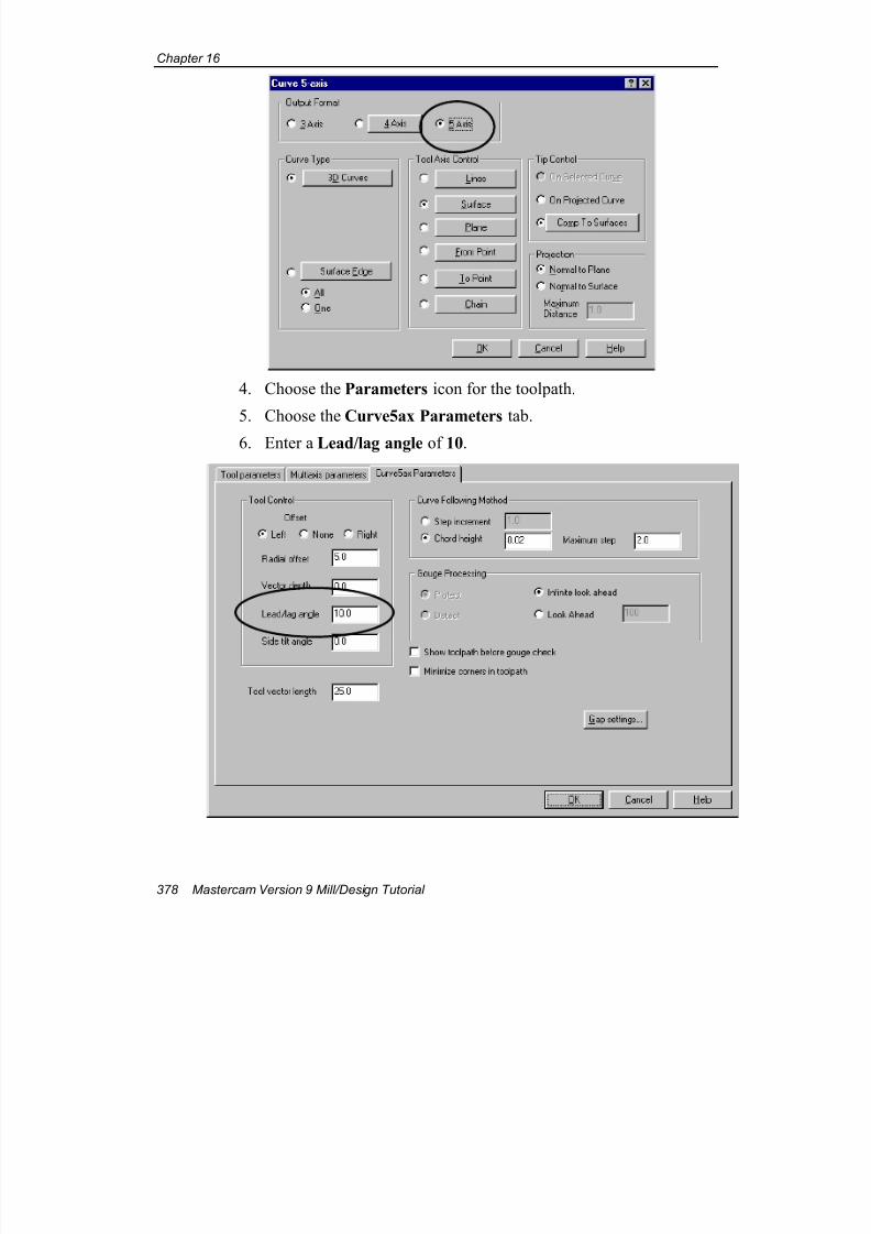
7/18/2019 V9 Mill-Design Tutorial (metric).pdf
http://slidepdf.com/reader/full/v9-mill-design-tutorial-metricpdf 390/453
Chapter 16
378 Mastercam Version 9 Mill/Design Tutorial
4. Choose the Parameters icon for the toolpath.
5. Choose the Curve5ax Parameters tab.
6. Enter a Lead/lag angle of 10.
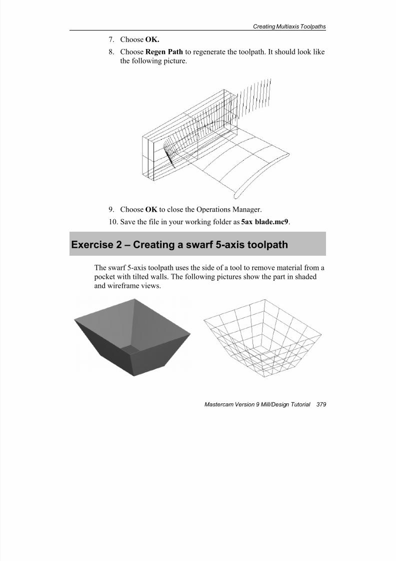
7/18/2019 V9 Mill-Design Tutorial (metric).pdf
http://slidepdf.com/reader/full/v9-mill-design-tutorial-metricpdf 391/453
Creating Multiaxis Toolpaths
Mastercam Version 9 Mill/Design Tutorial 379
7. Choose OK.
8. Choose Regen Path to regenerate the toolpath. It should look like
the following picture.
9. Choose OK to close the Operations Manager.
10. Save the file in your working folder as 5ax blade.mc9.
Exercise 2 – Creating a swarf 5-axis toolpath
The swarf 5-axis toolpath uses the side of a tool to remove material from a
pocket with tilted walls. The following pictures show the part in shaded
and wireframe views.
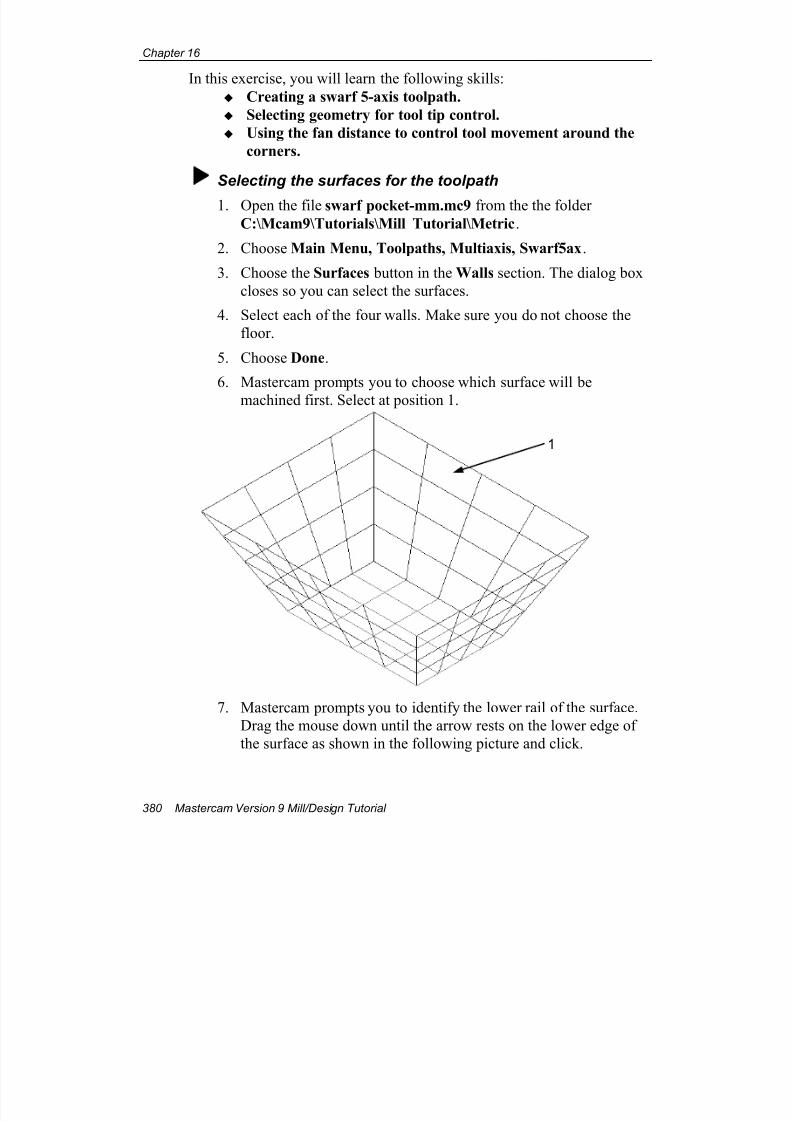
7/18/2019 V9 Mill-Design Tutorial (metric).pdf
http://slidepdf.com/reader/full/v9-mill-design-tutorial-metricpdf 392/453
Chapter 16
380 Mastercam Version 9 Mill/Design Tutorial
In this exercise, you will learn the following skills:
Creating a swarf 5-axis toolpath.
Selecting geometry for tool tip control.
Using the fan distance to control tool movement around the
corners.
Selecting the surfaces for the toolpath
1. Open the file swarf pocket-mm.mc9 from the the folder
C:\Mcam9\Tutorials\Mill Tutorial\Metric.
2. Choose Main Menu, Toolpaths, Multiaxis, Swarf5ax.
3. Choose the Surfaces button in the Walls section. The dialog box
closes so you can select the surfaces.
4. Select each of the four walls. Make sure you do not choose the
floor.
5. Choose Done.
6. Mastercam prompts you to choose which surface will be
machined first. Select at position 1.
7. Mastercam prompts you to identify the lower rail of the surface.
Drag the mouse down until the arrow rests on the lower edge of
the surface as shown in the following picture and click.
1
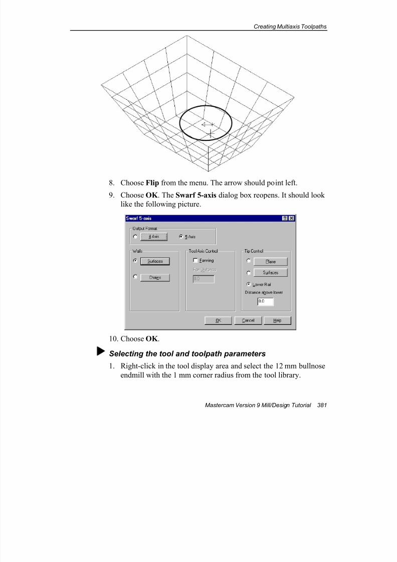
7/18/2019 V9 Mill-Design Tutorial (metric).pdf
http://slidepdf.com/reader/full/v9-mill-design-tutorial-metricpdf 393/453
Creating Multiaxis Toolpaths
Mastercam Version 9 Mill/Design Tutorial 381
8. Choose Flip from the menu. The arrow should point left.
9. Choose OK . The Swarf 5-axis dialog box reopens. It should looklike the following picture.
10. Choose OK .
Selecting the tool and toolpath parameters
1. Right-click in the tool display area and select the 12 mm bullnose
endmill with the 1 mm corner radius from the tool library.
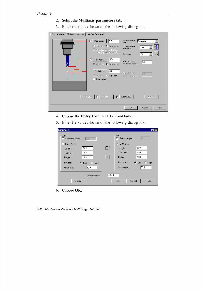
7/18/2019 V9 Mill-Design Tutorial (metric).pdf
http://slidepdf.com/reader/full/v9-mill-design-tutorial-metricpdf 394/453
Chapter 16
382 Mastercam Version 9 Mill/Design Tutorial
2. Select the Multiaxis parameters tab.
3. Enter the values shown on the following dialog box.
4. Choose the Entry/Exit check box and button.
5. Enter the values shown on the following dialog box.
6. Choose OK .
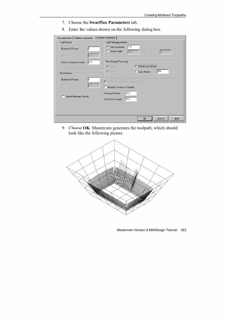
7/18/2019 V9 Mill-Design Tutorial (metric).pdf
http://slidepdf.com/reader/full/v9-mill-design-tutorial-metricpdf 395/453
Creating Multiaxis Toolpaths
Mastercam Version 9 Mill/Design Tutorial 383
7. Choose the Swarf5ax Parameters tab.
8. Enter the values shown on the following dialog box.
9. Choose OK . Mastercam generates the toolpath, which should
look like the following picture.
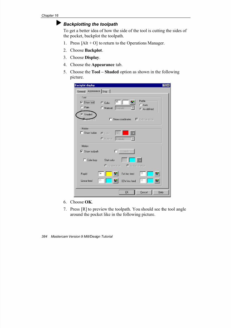
7/18/2019 V9 Mill-Design Tutorial (metric).pdf
http://slidepdf.com/reader/full/v9-mill-design-tutorial-metricpdf 396/453
Chapter 16
384 Mastercam Version 9 Mill/Design Tutorial
Backplotting the toolpath
To get a better idea of how the side of the tool is cutting the sides of
the pocket, backplot the toolpath.
1. Press [Alt + O] to return to the Operations Manager.
2. Choose Backplot.
3. Choose Display.
4. Choose the Appearance tab.
5. Choose the Tool – Shaded option as shown in the following
picture.
6. Choose OK .
7. Press [R] to preview the toolpath. You should see the tool angle
around the pocket like in the following picture.
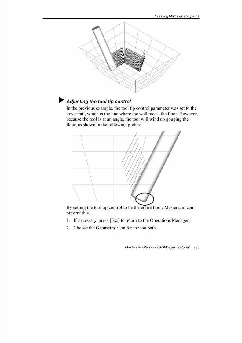
7/18/2019 V9 Mill-Design Tutorial (metric).pdf
http://slidepdf.com/reader/full/v9-mill-design-tutorial-metricpdf 397/453
Creating Multiaxis Toolpaths
Mastercam Version 9 Mill/Design Tutorial 385
Adjusting the tool tip control
In the previous example, the tool tip control parameter was set to the
lower rail, which is the line where the wall meets the floor. However,
because the tool is at an angle, the tool will wind up gouging thefloor, as shown in the following picture.
By setting the tool tip control to be the entire floor, Mastercam can
prevent this.
1. If necessary, press [Esc] to return to the Operations Manager.
2. Choose the Geometry icon for the toolpath.
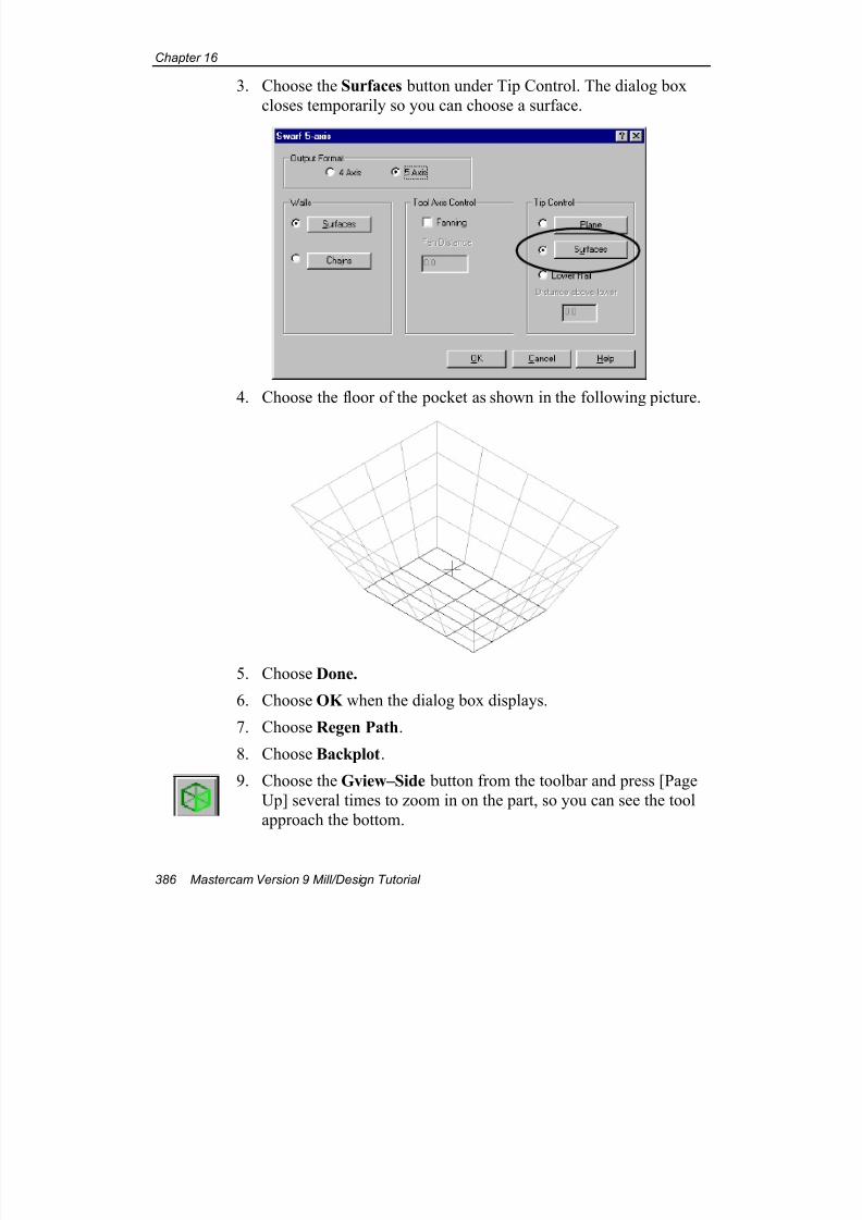
7/18/2019 V9 Mill-Design Tutorial (metric).pdf
http://slidepdf.com/reader/full/v9-mill-design-tutorial-metricpdf 398/453
Chapter 16
386 Mastercam Version 9 Mill/Design Tutorial
3. Choose the Surfaces button under Tip Control. The dialog box
closes temporarily so you can choose a surface.
4. Choose the floor of the pocket as shown in the following picture.
5. Choose Done.
6. Choose OK when the dialog box displays.
7. Choose Regen Path.
8. Choose Backplot.
9. Choose the Gview–Side button from the toolbar and press [Page
Up] several times to zoom in on the part, so you can see the tool
approach the bottom.
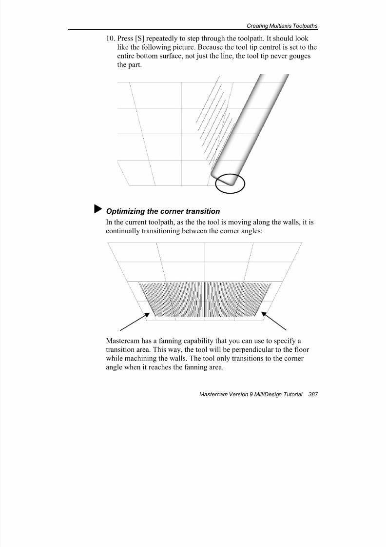
7/18/2019 V9 Mill-Design Tutorial (metric).pdf
http://slidepdf.com/reader/full/v9-mill-design-tutorial-metricpdf 399/453
Creating Multiaxis Toolpaths
Mastercam Version 9 Mill/Design Tutorial 387
10. Press [S] repeatedly to step through the toolpath. It should look
like the following picture. Because the tool tip control is set to the
entire bottom surface, not just the line, the tool tip never gouges
the part.
Optimizing the corner transition
In the current toolpath, as the the tool is moving along the walls, it is
continually transitioning between the corner angles:
Mastercam has a fanning capability that you can use to specify a
transition area. This way, the tool will be perpendicular to the floor
while machining the walls. The tool only transitions to the corner
angle when it reaches the fanning area.
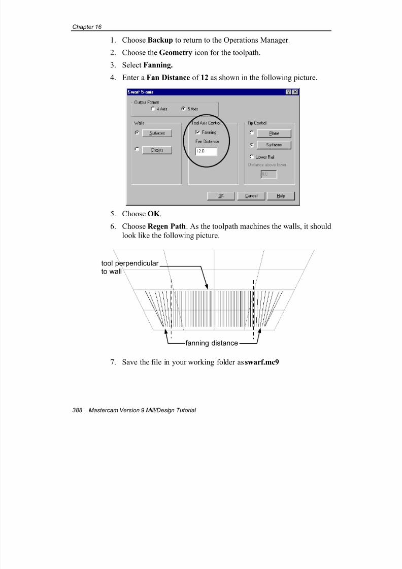
7/18/2019 V9 Mill-Design Tutorial (metric).pdf
http://slidepdf.com/reader/full/v9-mill-design-tutorial-metricpdf 400/453
Chapter 16
388 Mastercam Version 9 Mill/Design Tutorial
1. Choose Backup to return to the Operations Manager.
2. Choose the Geometry icon for the toolpath.
3. Select Fanning.
4. Enter a Fan Distance of 12 as shown in the following picture.
5. Choose OK .
6. Choose Regen Path. As the toolpath machines the walls, it should
look like the following picture.
7. Save the file in your working folder as swarf.mc9
fanning distance
tool perpendicularto wall

7/18/2019 V9 Mill-Design Tutorial (metric).pdf
http://slidepdf.com/reader/full/v9-mill-design-tutorial-metricpdf 401/453
Creating Multiaxis Toolpaths
Mastercam Version 9 Mill/Design Tutorial 389
This exercise completes your introduction to creating multiaxis toolpaths
in Mastercam. You can learn about Mastercam's other types of multiaxis
toolpaths—drill, multisurface, flowline, and rotary—in the online help.
The next chapter, which is the final exercise in this tutorial, shows you an
example of machining a solid and introduces Mastercam's feature-based
solid drilling function.
Note: You need a Mastercam Solids license to complete the next chapter .

7/18/2019 V9 Mill-Design Tutorial (metric).pdf
http://slidepdf.com/reader/full/v9-mill-design-tutorial-metricpdf 402/453
Chapter 16
390 Mastercam Version 9 Mill/Design Tutorial
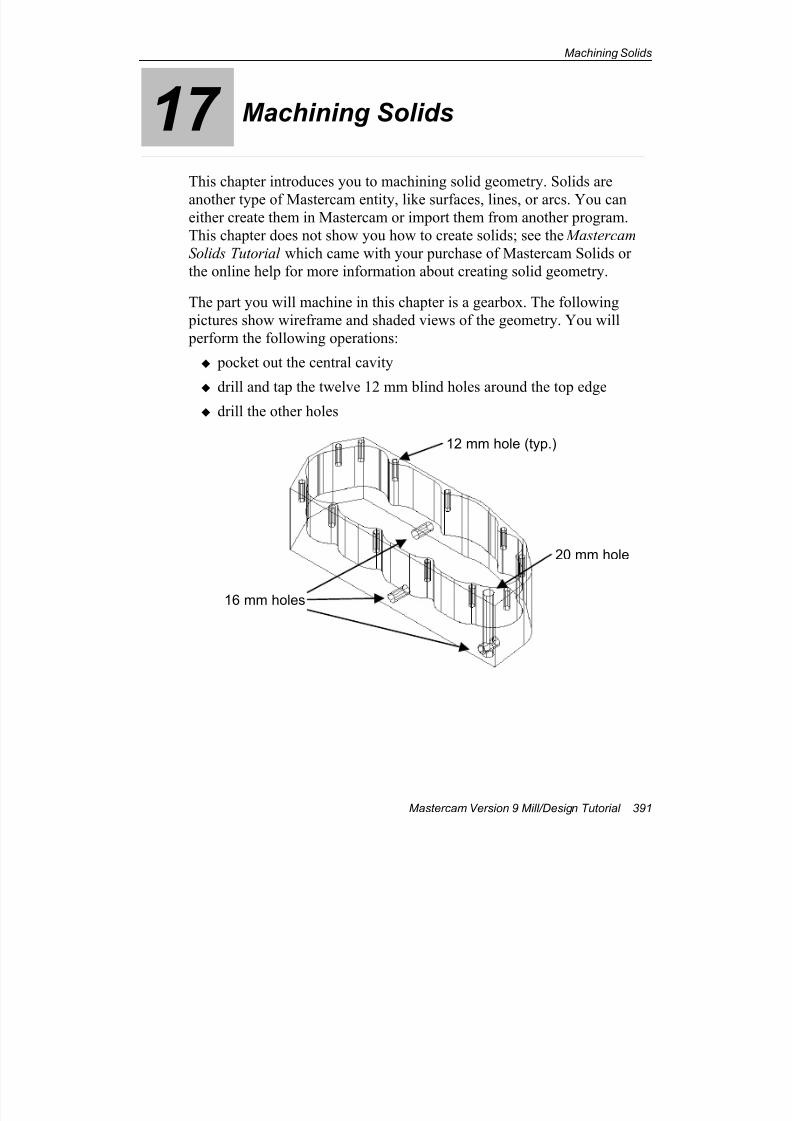
7/18/2019 V9 Mill-Design Tutorial (metric).pdf
http://slidepdf.com/reader/full/v9-mill-design-tutorial-metricpdf 403/453
Machining Solids
Mastercam Version 9 Mill/Design Tutorial 391
17 Machining Solids
This chapter introduces you to machining solid geometry. Solids are
another type of Mastercam entity, like surfaces, lines, or arcs. You caneither create them in Mastercam or import them from another program.
This chapter does not show you how to create solids; see the Mastercam
Solids Tutorial which came with your purchase of Mastercam Solids or
the online help for more information about creating solid geometry.
The part you will machine in this chapter is a gearbox. The following
pictures show wireframe and shaded views of the geometry. You will
perform the following operations:
pocket out the central cavity
drill and tap the twelve 12 mm blind holes around the top edge drill the other holes
20 mm hole
16 mm holes
12 mm hole (typ.)
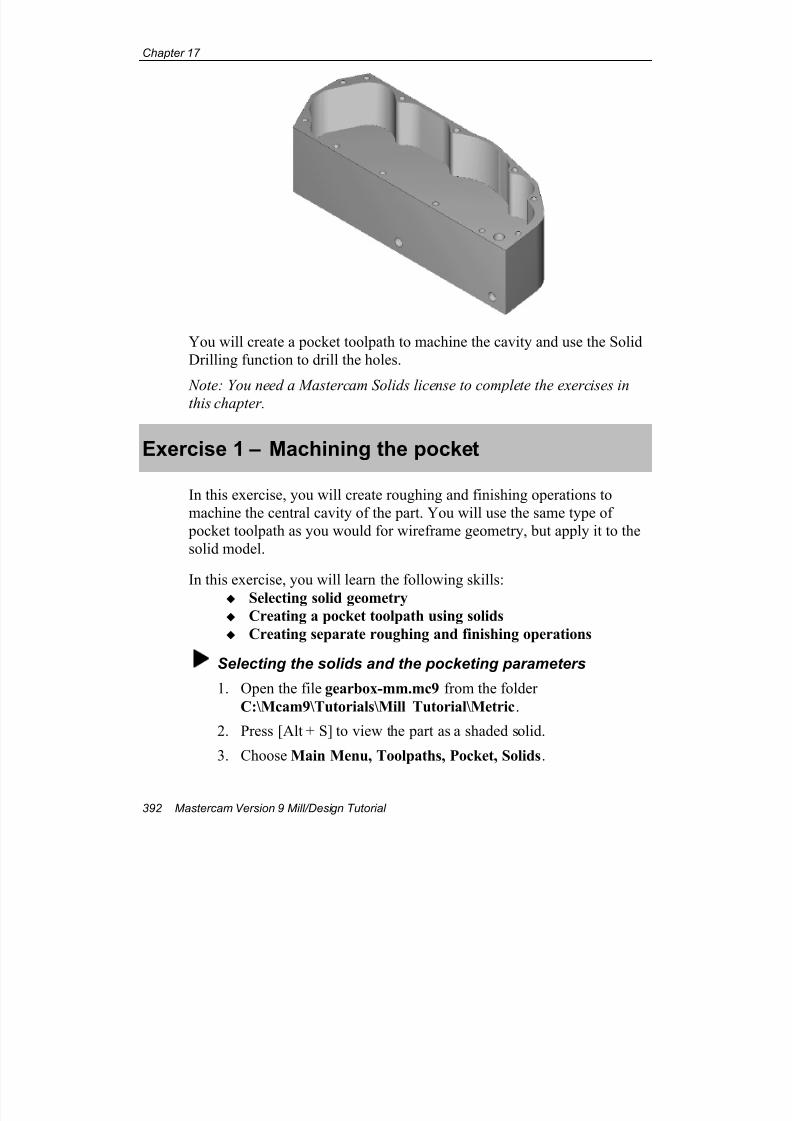
7/18/2019 V9 Mill-Design Tutorial (metric).pdf
http://slidepdf.com/reader/full/v9-mill-design-tutorial-metricpdf 404/453
Chapter 17
392 Mastercam Version 9 Mill/Design Tutorial
You will create a pocket toolpath to machine the cavity and use the Solid
Drilling function to drill the holes.
Note: You need a Mastercam Solids license to complete the exercises inthis chapter.
Exercise 1 – Machining the pocket
In this exercise, you will create roughing and finishing operations to
machine the central cavity of the part. You will use the same type of
pocket toolpath as you would for wireframe geometry, but apply it to the
solid model.
In this exercise, you will learn the following skills:
Selecting solid geometry
Creating a pocket toolpath using solids
Creating separate roughing and finishing operations
Selecting the solids and the pocketing parameters
1. Open the file gearbox-mm.mc9 from the folder
C:\Mcam9\Tutorials\Mill Tutorial\Metric.
2. Press [Alt + S] to view the part as a shaded solid.
3. Choose Main Menu, Toolpaths, Pocket, Solids.
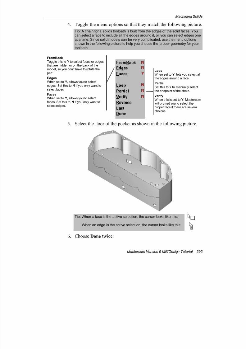
7/18/2019 V9 Mill-Design Tutorial (metric).pdf
http://slidepdf.com/reader/full/v9-mill-design-tutorial-metricpdf 405/453
Machining Solids
Mastercam Version 9 Mill/Design Tutorial 393
4. Toggle the menu options so that they match the following picture.
Tip: A chain for a solids toolpath is built from the edges of the solid faces. Youcan select a face to include all the edges around it, or you can select edges oneat a time. Since solid models can be very complicated, use the menu optionsshown in the following picture to help you choose the proper geometry for yourtoolpath.
5. Select the floor of the pocket as shown in the following picture.
Tip: When a face is the active selection, the cursor looks like this:
When an edge is the active selection, the cursor looks like this:
6. Choose Done twice.
FromBack
Toggle this to Y to select faces or edgesthat are hidden or on the back of the
model, so you don't have to rotate the
part.
Edges
When set to Y, allows you to select
edges. Set this to N if you only want to
select faces.
Faces
When set to Y, allows you to selectfaces. Set this to N if you only want to
select edges.
Loop
When set to Y, lets you select all
the edges around a face.
Partial
Set this to Y to manually select
the endpoint of the chain.
Verify
When this is set to Y, Mastercamwill prompt you to select the
proper face if there are several
choices.
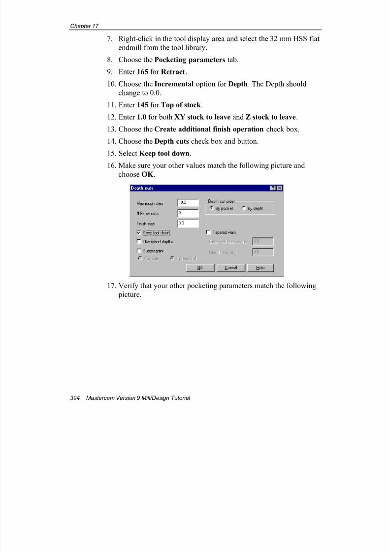
7/18/2019 V9 Mill-Design Tutorial (metric).pdf
http://slidepdf.com/reader/full/v9-mill-design-tutorial-metricpdf 406/453
Chapter 17
394 Mastercam Version 9 Mill/Design Tutorial
7. Right-click in the tool display area and select the 32 mm HSS flat
endmill from the tool library.
8. Choose the Pocketing parameters tab.
9. Enter 165 for Retract.
10. Choose the Incremental option for Depth. The Depth should
change to 0.0.11. Enter 145 for Top of stock .
12. Enter 1.0 for both XY stock to leave and Z stock to leave.
13. Choose the Create additional finish operation check box.
14. Choose the Depth cuts check box and button.
15. Select Keep tool down.
16. Make sure your other values match the following picture and
choose OK .
17. Verify that your other pocketing parameters match the following
picture.
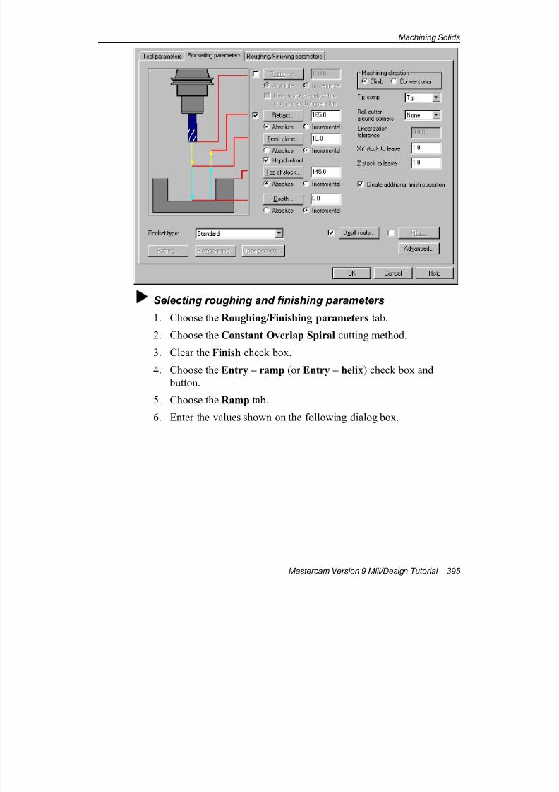
7/18/2019 V9 Mill-Design Tutorial (metric).pdf
http://slidepdf.com/reader/full/v9-mill-design-tutorial-metricpdf 407/453
Machining Solids
Mastercam Version 9 Mill/Design Tutorial 395
Selecting roughing and finishing parameters
1. Choose the Roughing/Finishing parameters tab.
2. Choose the Constant Overlap Spiral cutting method.
3. Clear the Finish check box.
4. Choose the Entry – ramp (or Entry – helix) check box and
button.
5. Choose the Ramp tab.
6. Enter the values shown on the following dialog box.
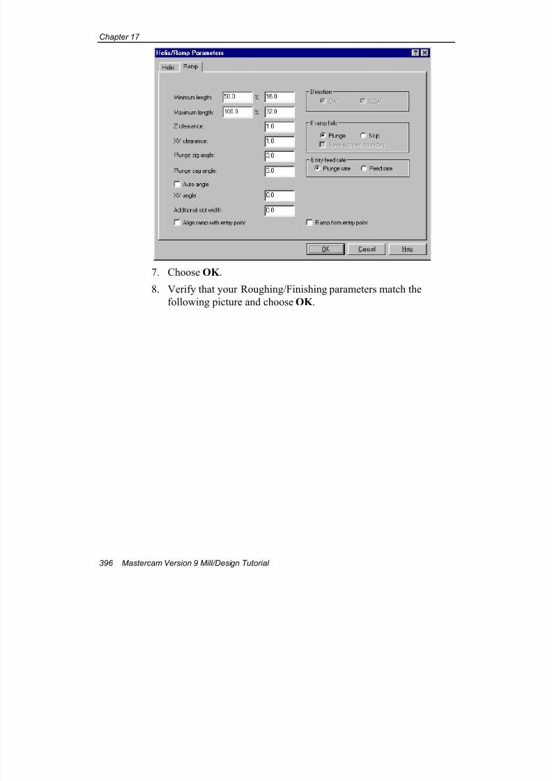
7/18/2019 V9 Mill-Design Tutorial (metric).pdf
http://slidepdf.com/reader/full/v9-mill-design-tutorial-metricpdf 408/453
Chapter 17
396 Mastercam Version 9 Mill/Design Tutorial
7. Choose OK .8. Verify that your Roughing/Finishing parameters match the
following picture and choose OK .
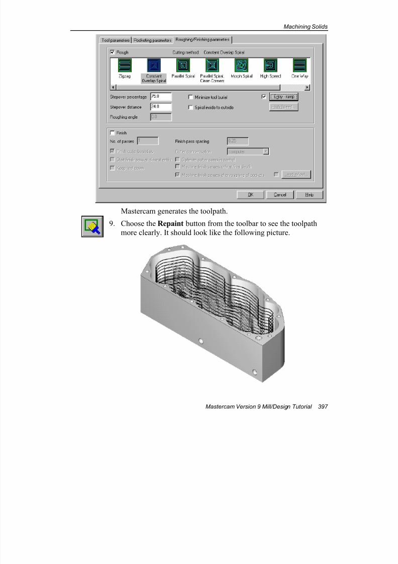
7/18/2019 V9 Mill-Design Tutorial (metric).pdf
http://slidepdf.com/reader/full/v9-mill-design-tutorial-metricpdf 409/453
Machining Solids
Mastercam Version 9 Mill/Design Tutorial 397
Mastercam generates the toolpath.
9. Choose the Repaint button from the toolbar to see the toolpath
more clearly. It should look like the following picture.
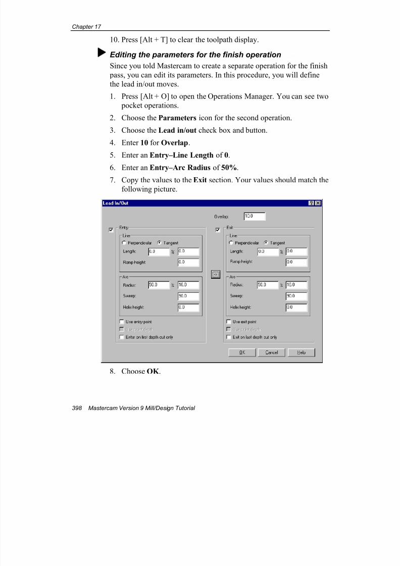
7/18/2019 V9 Mill-Design Tutorial (metric).pdf
http://slidepdf.com/reader/full/v9-mill-design-tutorial-metricpdf 410/453
Chapter 17
398 Mastercam Version 9 Mill/Design Tutorial
10. Press [Alt + T] to clear the toolpath display.
Editing the parameters for the finish operation
Since you told Mastercam to create a separate operation for the finish
pass, you can edit its parameters. In this procedure, you will define
the lead in/out moves.
1. Press [Alt + O] to open the Operations Manager. You can see two pocket operations.
2. Choose the Parameters icon for the second operation.
3. Choose the Lead in/out check box and button.
4. Enter 10 for Overlap.
5. Enter an Entry–Line Length of 0.
6. Enter an Entry–Arc Radius of 50%.
7. Copy the values to the Exit section. Your values should match the
following picture.
8. Choose OK .
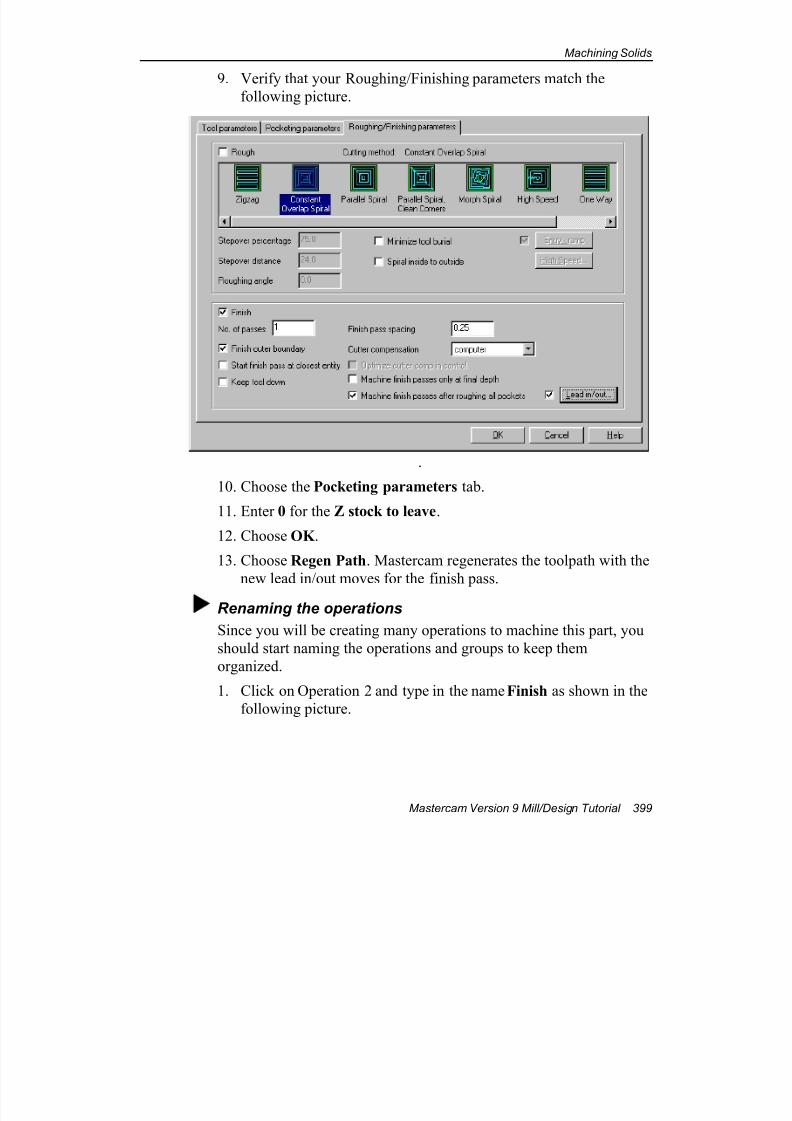
7/18/2019 V9 Mill-Design Tutorial (metric).pdf
http://slidepdf.com/reader/full/v9-mill-design-tutorial-metricpdf 411/453
Machining Solids
Mastercam Version 9 Mill/Design Tutorial 399
9. Verify that your Roughing/Finishing parameters match the
following picture.
.
10. Choose the Pocketing parameters tab.
11. Enter 0 for the Z stock to leave.
12. Choose OK .
13. Choose Regen Path. Mastercam regenerates the toolpath with the
new lead in/out moves for the finish pass.
Renaming the operations
Since you will be creating many operations to machine this part, you
should start naming the operations and groups to keep them
organized.
1. Click on Operation 2 and type in the name Finish as shown in the
following picture.
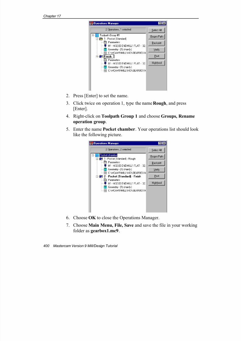
7/18/2019 V9 Mill-Design Tutorial (metric).pdf
http://slidepdf.com/reader/full/v9-mill-design-tutorial-metricpdf 412/453
Chapter 17
400 Mastercam Version 9 Mill/Design Tutorial
2. Press [Enter] to set the name.
3. Click twice on operation 1, type the name Rough, and press
[Enter].
4. Right-click on Toolpath Group 1 and choose Groups, Rename
operation group.
5. Enter the name Pocket chamber. Your operations list should look
like the following picture.
6. Choose OK to close the Operations Manager.
7. Choose Main Menu, File, Save and save the file in your working
folder as gearbox1.mc9.
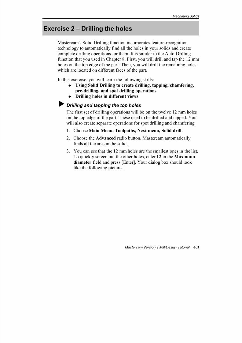
7/18/2019 V9 Mill-Design Tutorial (metric).pdf
http://slidepdf.com/reader/full/v9-mill-design-tutorial-metricpdf 413/453
Machining Solids
Mastercam Version 9 Mill/Design Tutorial 401
Exercise 2 – Drilling the holes
Mastercam's Solid Drilling function incorporates feature-recognition
technology to automatically find all the holes in your solids and create
complete drilling operations for them. It is similar to the Auto Drilling
function that you used in Chapter 8. First, you will drill and tap the 12 mmholes on the top edge of the part. Then, you will drill the remaining holes
which are located on different faces of the part.
In this exercise, you will learn the following skills:
Using Solid Drilling to create drilling, tapping, chamfering,
pre-drilling, and spot drilling operations
Drilling holes in different views
Drilling and tapping the top holes
The first set of drilling operations will be on the twelve 12 mm holes
on the top edge of the part. These need to be drilled and tapped. You
will also create separate operations for spot drilling and chamfering.
1. Choose Main Menu, Toolpaths, Next menu, Solid drill.
2. Choose the Advanced radio button. Mastercam automatically
finds all the arcs in the solid.
3. You can see that the 12 mm holes are the smallest ones in the list.
To quickly screen out the other holes, enter 12 in the Maximum
diameter field and press [Enter]. Your dialog box should look
like the following picture.
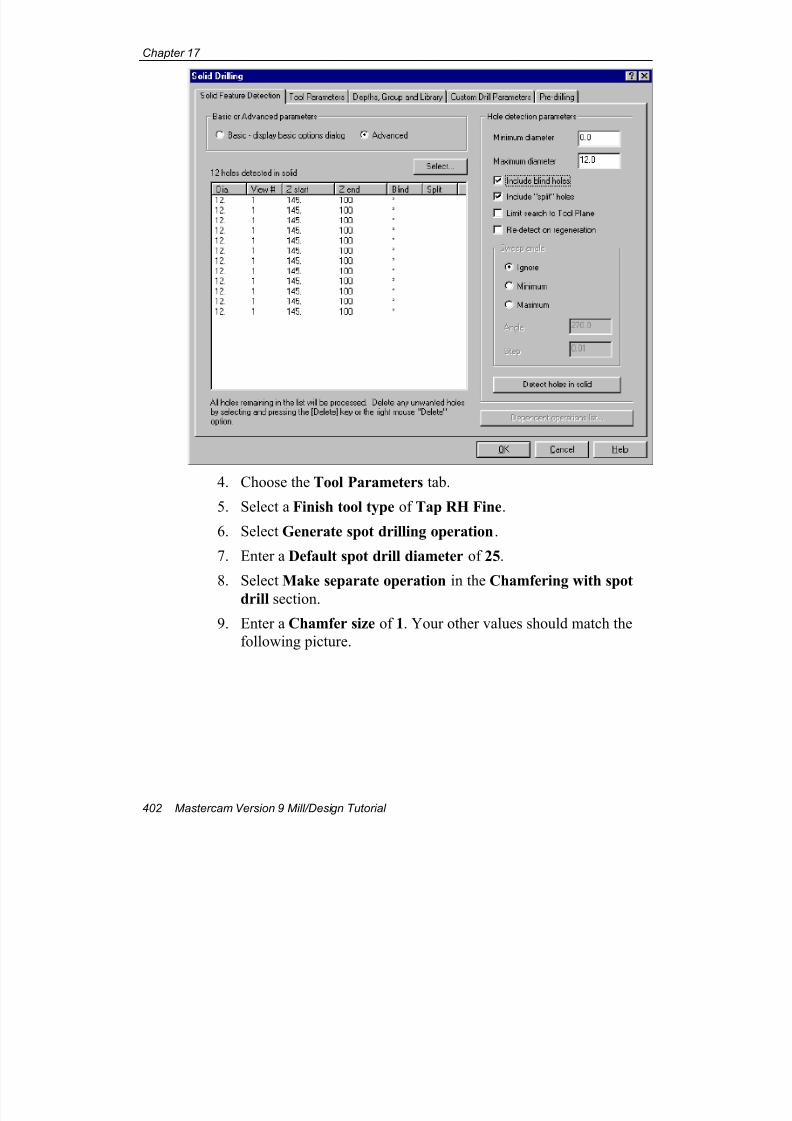
7/18/2019 V9 Mill-Design Tutorial (metric).pdf
http://slidepdf.com/reader/full/v9-mill-design-tutorial-metricpdf 414/453
Chapter 17
402 Mastercam Version 9 Mill/Design Tutorial
4. Choose the Tool Parameters tab.
5. Select a Finish tool type of Tap RH Fine.
6. Select Generate spot drilling operation.
7. Enter a Default spot drill diameter of 25.
8. Select Make separate operation in the Chamfering with spot
drill section.
9. Enter a Chamfer size of 1. Your other values should match the
following picture.
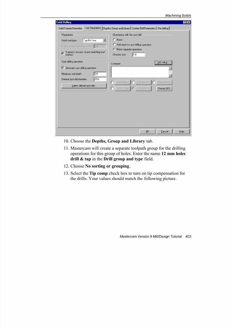
7/18/2019 V9 Mill-Design Tutorial (metric).pdf
http://slidepdf.com/reader/full/v9-mill-design-tutorial-metricpdf 415/453
Machining Solids
Mastercam Version 9 Mill/Design Tutorial 403
10. Choose the Depths, Group and Library tab.
11. Mastercam will create a separate toolpath group for the drilling
operations for this group of holes. Enter the name 12 mm holes
drill & tap in the Drill group and type field.
12. Choose No sorting or grouping.
13. Select the Tip comp check box to turn on tip compensation forthe drills. Your values should match the following picture.
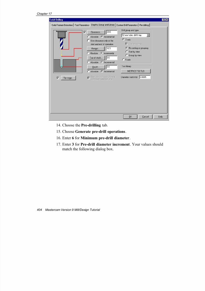
7/18/2019 V9 Mill-Design Tutorial (metric).pdf
http://slidepdf.com/reader/full/v9-mill-design-tutorial-metricpdf 416/453
Chapter 17
404 Mastercam Version 9 Mill/Design Tutorial
14. Choose the Pre-drilling tab.
15. Choose Generate pre-drill operations.
16. Enter 6 for Minimum pre-drill diameter.
17. Enter 3 for Pre-drill diameter increment. Your values should
match the following dialog box.
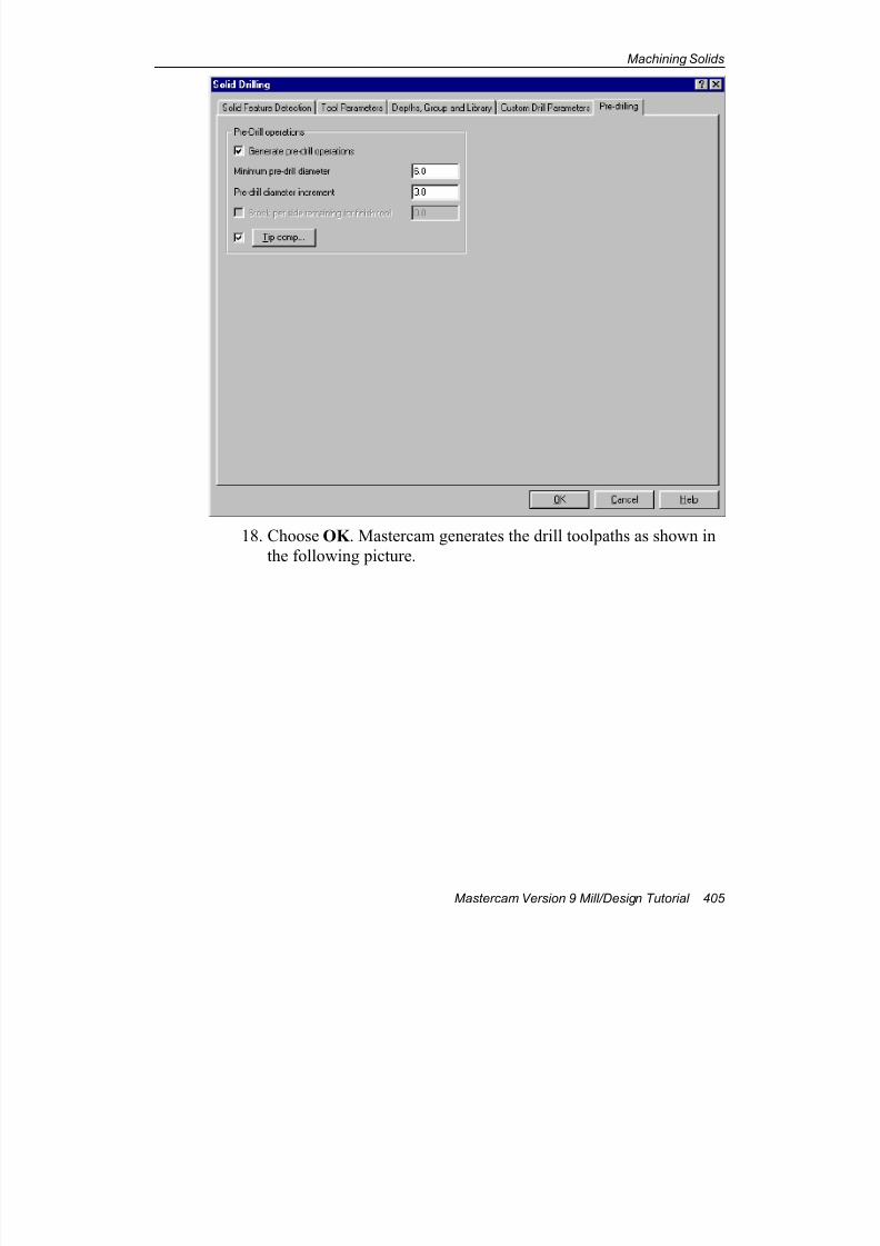
7/18/2019 V9 Mill-Design Tutorial (metric).pdf
http://slidepdf.com/reader/full/v9-mill-design-tutorial-metricpdf 417/453
Machining Solids
Mastercam Version 9 Mill/Design Tutorial 405
18. Choose OK . Mastercam generates the drill toolpaths as shown in
the following picture.
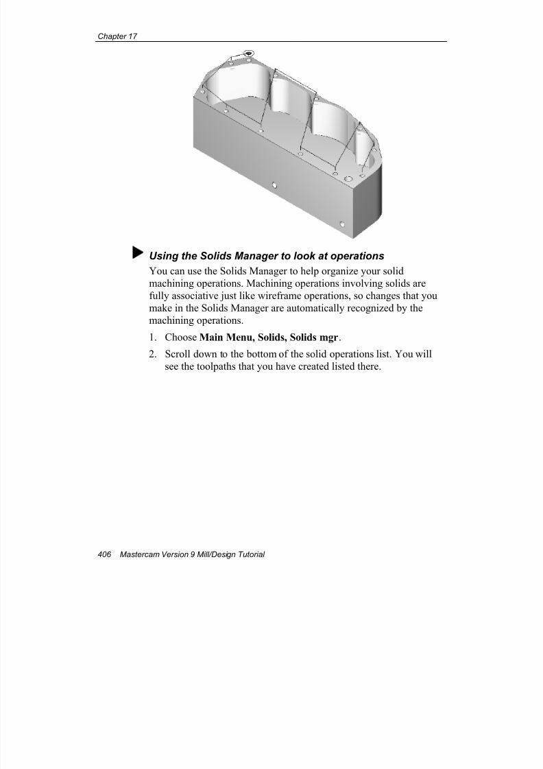
7/18/2019 V9 Mill-Design Tutorial (metric).pdf
http://slidepdf.com/reader/full/v9-mill-design-tutorial-metricpdf 418/453
Chapter 17
406 Mastercam Version 9 Mill/Design Tutorial
Using the Solids Manager to look at operations
You can use the Solids Manager to help organize your solidmachining operations. Machining operations involving solids are
fully associative just like wireframe operations, so changes that you
make in the Solids Manager are automatically recognized by the
machining operations.
1. Choose Main Menu, Solids, Solids mgr.
2. Scroll down to the bottom of the solid operations list. You will
see the toolpaths that you have created listed there.
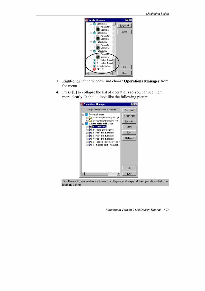
7/18/2019 V9 Mill-Design Tutorial (metric).pdf
http://slidepdf.com/reader/full/v9-mill-design-tutorial-metricpdf 419/453
Machining Solids
Mastercam Version 9 Mill/Design Tutorial 407
3. Right-click in the window and choose Operations Manager from
the menu.
4. Press [E] to collapse the list of operations so you can see them
more clearly. It should look like the following picture.
Tip: Press [E] several more times to collapse and expand the operations list onelevel at a time.

7/18/2019 V9 Mill-Design Tutorial (metric).pdf
http://slidepdf.com/reader/full/v9-mill-design-tutorial-metricpdf 420/453
Chapter 17
408 Mastercam Version 9 Mill/Design Tutorial
Drilling the remaining holes
You will use the Solid Drilling function again to create drilling
operations for the remaining holes. Solid Drilling automatically
recognizes that the remaining holes are different sizes and are located
on different faces of the part, and so need to be drilled from different
angles.
1. Right-click in the Operations Manager and choose Toolpaths,
Solids, Drilling.
2. Choose Advanced. Mastercam reads all the arcs in the solid.
Mastercam lists a number of arcs that you do not want to include
in this operation, so you will filter them out by their diameter.
3. Type in a Minimum diameter of 13. The holes smaller than this
were drilled and tapped in the previous procedure, so you don’t
want to include them here.
4. Type in a Maximum diameter of 20 and press [Enter]. The arcs
larger than this are in the contour of the pocket, not drilling holes,so you don't want to include them either.
Your selections should match the following picture.
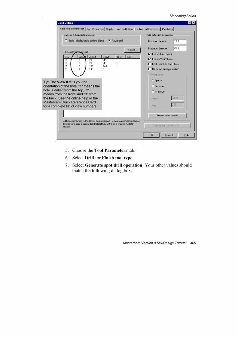
7/18/2019 V9 Mill-Design Tutorial (metric).pdf
http://slidepdf.com/reader/full/v9-mill-design-tutorial-metricpdf 421/453
Machining Solids
Mastercam Version 9 Mill/Design Tutorial 409
5. Choose the Tool Parameters tab.
6. Select Drill for Finish tool type.
7. Select Generate spot drill operation. Your other values should
match the following dialog box.
Tip: The View # tells you theorientation of the hole. "1" means thehole is drilled from the top, "2"means from the front, and "3" fromthe back. See the online help or theMastercam Quick Reference Cardfor a complete list of view numbers.
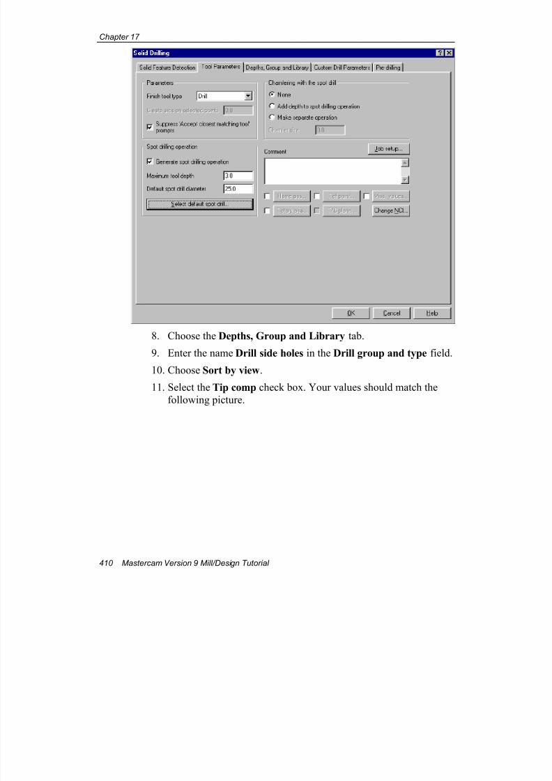
7/18/2019 V9 Mill-Design Tutorial (metric).pdf
http://slidepdf.com/reader/full/v9-mill-design-tutorial-metricpdf 422/453
Chapter 17
410 Mastercam Version 9 Mill/Design Tutorial
8. Choose the Depths, Group and Library tab.
9. Enter the name Drill side holes in the Drill group and type field.
10. Choose Sort by view.
11. Select the Tip comp check box. Your values should match the
following picture.
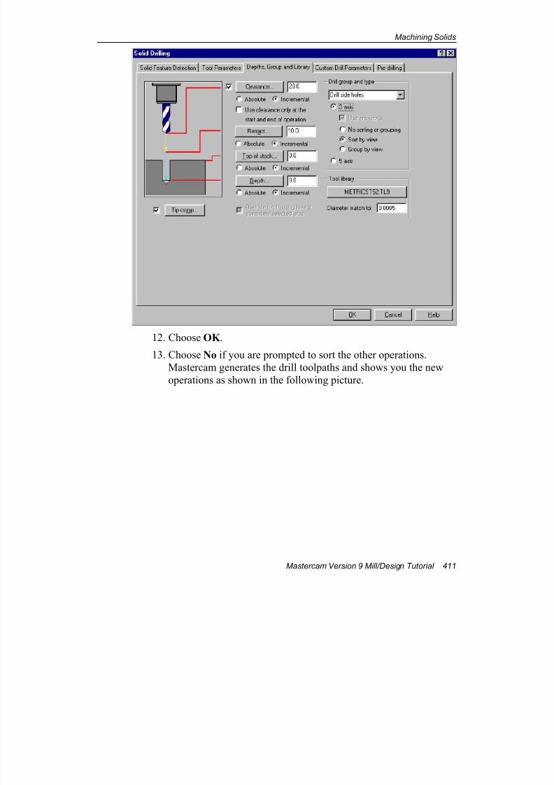
7/18/2019 V9 Mill-Design Tutorial (metric).pdf
http://slidepdf.com/reader/full/v9-mill-design-tutorial-metricpdf 423/453
Machining Solids
Mastercam Version 9 Mill/Design Tutorial 411
12. Choose OK .
13. Choose No if you are prompted to sort the other operations.
Mastercam generates the drill toolpaths and shows you the new
operations as shown in the following picture.
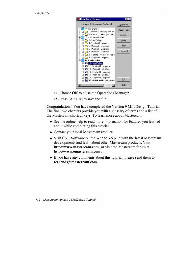
7/18/2019 V9 Mill-Design Tutorial (metric).pdf
http://slidepdf.com/reader/full/v9-mill-design-tutorial-metricpdf 424/453
Chapter 17
412 Mastercam Version 9 Mill/Design Tutorial
14. Choose OK to close the Operations Manager.
15. Press [Alt + A] to save the file.
Congratulations! You have completed the Version 9 Mill/Design Tutorial.
The final two chapters provide you with a glossary of terms and a list of
the Mastercam shortcut keys. To learn more about Mastercam:
See the online help to read more information for features you learned
about while completing this tutorial.
Contact your local Mastercam reseller.
Visit CNC Software on the Web to keep up with the latest Mastercam
developments and learn about other Mastercam products. Visit
http://www.mastercam.com, or visit the Mastercam forum athttp://www.emastercam.com.
If you have any comments about this tutorial, please send them to
7/18/2019 V9 Mill-Design Tutorial (metric).pdf
http://slidepdf.com/reader/full/v9-mill-design-tutorial-metricpdf 425/453
Glossary
Mastercam Version 9 Mill/Design Tutorial 413
18 Glossary
2 ½D (contour) A toolpath consisting of multiple sections in which the
depth can vary between sections but is constant within a
section.
2D (contour or plane)
A toolpath or geometry that lies in a single plane.
3D (contour, plane
or space)
A toolpath or geometry defined in X, Y, and Z axes
simultaneously; consists of lines, arc, parametric splines,
and NURBS splines.
4-axis Toolpaths defined by X, Y, and Z locations, but with atool axis with an additional degree of freedom, permitting
the tool to be oriented parallel to an axis other than X, Y,or Z.
5-axis Toolpaths defined by X, Y, and Z locations, but with atool axis with two additional degrees of freedom,
permitting the tool to be oriented parallel to an axis other
than X, Y, or Z.
A
A axis Axis of circular motion about the X axis; expressed in
degrees.
absolute(coordinates,
dimensioning,
positioning)
Measured from a fixed reference point, usually 0,0,0.
across chain When creating swept toolpaths, this is the profile to beswept along the curve.
AI Extension for Adobe Illustrator files. This is a common
vector graphics format.
7/18/2019 V9 Mill-Design Tutorial (metric).pdf
http://slidepdf.com/reader/full/v9-mill-design-tutorial-metricpdf 426/453
Chapter 18
414 Mastercam Version 9 Mill/Design Tutorial
along chain When creating swept toolpaths, this is the curve along
which the profile is swept.
along entity A series of evenly spaced points along a line, arc, orspline.
arc An open or closed planar curve in which all positions are
at a fixed distance (radius) from the center of the curve. A
circle is a 360-degree arc.
associativity(toolpath,
dimensioning, and
solids)
A relationship that links geometry with toolpath, tool,material, and parameter information to create a complete
toolpath operation. Permits modifications to geometry or
machining parameters to easily regenerate accurate,updated solid topology, dimensions and toolpaths. Also
the relationship between dimensioning and its geometry.
attribute data Attributes of entities: level, color, style, width.
AutoCursor A feature that snaps the cursor to endpoints, midpoints,
intersections, center points, quadrants or an arc, and theorigin points in the vicinity of the cursor; automates and
speeds point detection.
AutoHighlight A feature that speeds and simplifies entity selection by
dynamically highlighting the entity under the cursor before then entity is actually selected.
AutoSave Feature that automatically saves current geometry and
operations at a regular time interval.
B
B axis Axis of circular motion about the Y axis; expressed indegrees.
backplot Preview a toolpath, either step-by-step or continuously.
batch processing Method for generating nesting results for several nesting
sessions at the same time.
bitmap A graphic composed of small dots, or pixels. Bitmap filesuse the BMP or PCX extension, and are often produced by
scanning. See also raster, vector.
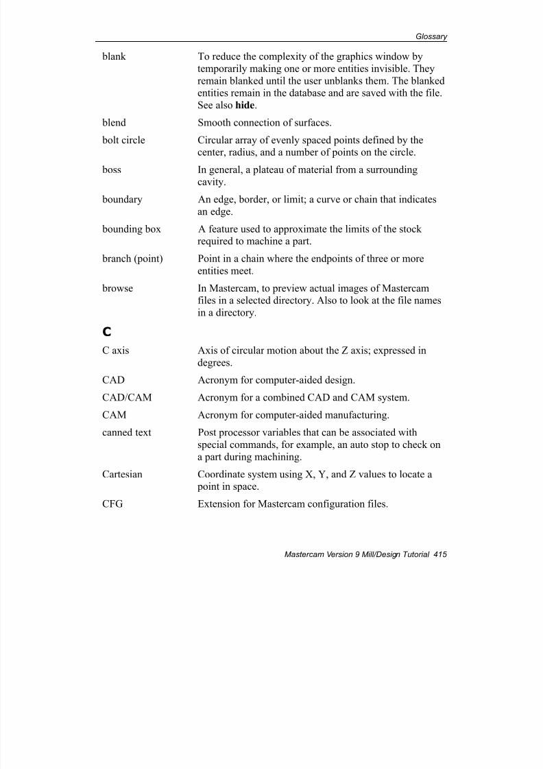
7/18/2019 V9 Mill-Design Tutorial (metric).pdf
http://slidepdf.com/reader/full/v9-mill-design-tutorial-metricpdf 427/453
Glossary
Mastercam Version 9 Mill/Design Tutorial 415
blank To reduce the complexity of the graphics window by
temporarily making one or more entities invisible. They
remain blanked until the user unblanks them. The blankedentities remain in the database and are saved with the file.
See also hide.
blend Smooth connection of surfaces.
bolt circle Circular array of evenly spaced points defined by thecenter, radius, and a number of points on the circle.
boss In general, a plateau of material from a surrounding
cavity.
boundary An edge, border, or limit; a curve or chain that indicates
an edge.
bounding box A feature used to approximate the limits of the stockrequired to machine a part.
branch (point) Point in a chain where the endpoints of three or more
entities meet.
browse In Mastercam, to preview actual images of Mastercamfiles in a selected directory. Also to look at the file names
in a directory.
C
C axis Axis of circular motion about the Z axis; expressed in
degrees.
CAD Acronym for computer-aided design.
CAD/CAM Acronym for a combined CAD and CAM system.
CAM Acronym for computer-aided manufacturing.
canned text Post processor variables that can be associated with
special commands, for example, an auto stop to check on
a part during machining.
Cartesian Coordinate system using X, Y, and Z values to locate a point in space.
CFG Extension for Mastercam configuration files.
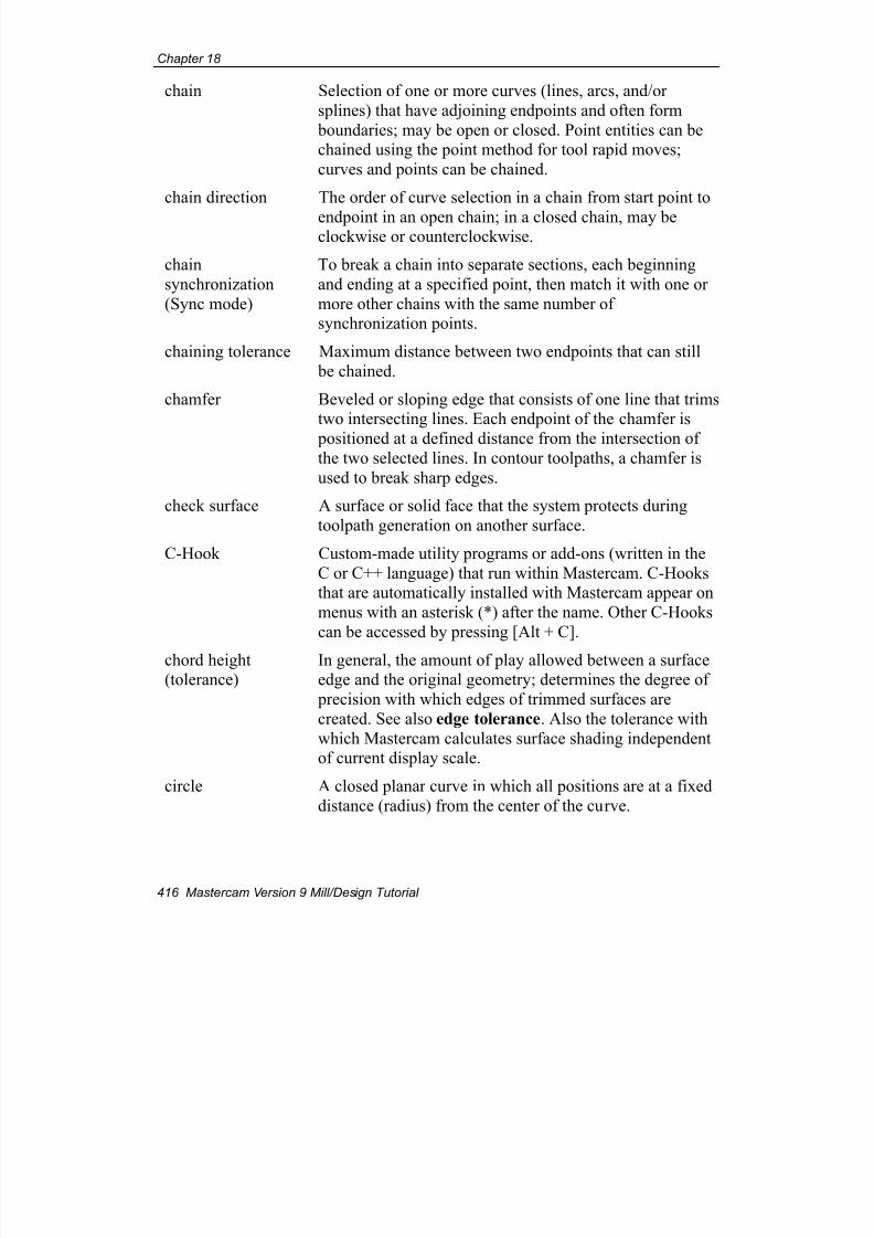
7/18/2019 V9 Mill-Design Tutorial (metric).pdf
http://slidepdf.com/reader/full/v9-mill-design-tutorial-metricpdf 428/453
Chapter 18
416 Mastercam Version 9 Mill/Design Tutorial
chain Selection of one or more curves (lines, arcs, and/or
splines) that have adjoining endpoints and often form
boundaries; may be open or closed. Point entities can bechained using the point method for tool rapid moves;
curves and points can be chained.
chain direction The order of curve selection in a chain from start point to
endpoint in an open chain; in a closed chain, may beclockwise or counterclockwise.
chain
synchronization
(Sync mode)
To break a chain into separate sections, each beginning
and ending at a specified point, then match it with one or
more other chains with the same number ofsynchronization points.
chaining tolerance Maximum distance between two endpoints that can still
be chained.
chamfer Beveled or sloping edge that consists of one line that trimstwo intersecting lines. Each endpoint of the chamfer is
positioned at a defined distance from the intersection ofthe two selected lines. In contour toolpaths, a chamfer is
used to break sharp edges.
check surface A surface or solid face that the system protects during
toolpath generation on another surface.
C-Hook Custom-made utility programs or add-ons (written in the
C or C++ language) that run within Mastercam. C-Hooksthat are automatically installed with Mastercam appear on
menus with an asterisk (*) after the name. Other C-Hooks
can be accessed by pressing [Alt + C].
chord height(tolerance)
In general, the amount of play allowed between a surfaceedge and the original geometry; determines the degree of
precision with which edges of trimmed surfaces are
created. See also edge tolerance. Also the tolerance with
which Mastercam calculates surface shading independentof current display scale.
circle A closed planar curve in which all positions are at a fixed
distance (radius) from the center of the curve.
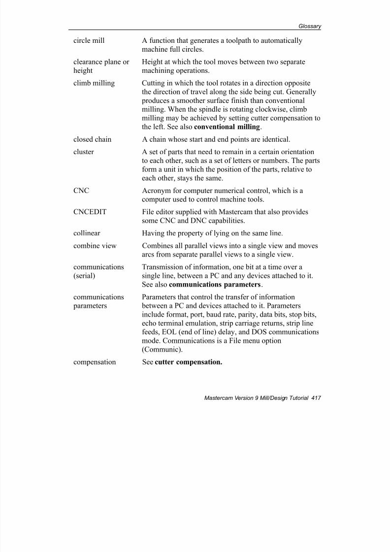
7/18/2019 V9 Mill-Design Tutorial (metric).pdf
http://slidepdf.com/reader/full/v9-mill-design-tutorial-metricpdf 429/453
Glossary
Mastercam Version 9 Mill/Design Tutorial 417
circle mill A function that generates a toolpath to automatically
machine full circles.
clearance plane orheight
Height at which the tool moves between two separatemachining operations.
climb milling Cutting in which the tool rotates in a direction opposite
the direction of travel along the side being cut. Generally
produces a smoother surface finish than conventionalmilling. When the spindle is rotating clockwise, climb
milling may be achieved by setting cutter compensation to
the left. See also conventional milling.
closed chain A chain whose start and end points are identical.
cluster A set of parts that need to remain in a certain orientationto each other, such as a set of letters or numbers. The parts
form a unit in which the position of the parts, relative to
each other, stays the same.
CNC Acronym for computer numerical control, which is acomputer used to control machine tools.
CNCEDIT File editor supplied with Mastercam that also provides
some CNC and DNC capabilities.
collinear Having the property of lying on the same line.
combine view Combines all parallel views into a single view and movesarcs from separate parallel views to a single view.
communications
(serial)
Transmission of information, one bit at a time over a
single line, between a PC and any devices attached to it.
See also communications parameters.
communications parameters
Parameters that control the transfer of information between a PC and devices attached to it. Parameters
include format, port, baud rate, parity, data bits, stop bits,
echo terminal emulation, strip carriage returns, strip linefeeds, EOL (end of line) delay, and DOS communications
mode. Communications is a File menu option
(Communic).
compensation See cutter compensation.
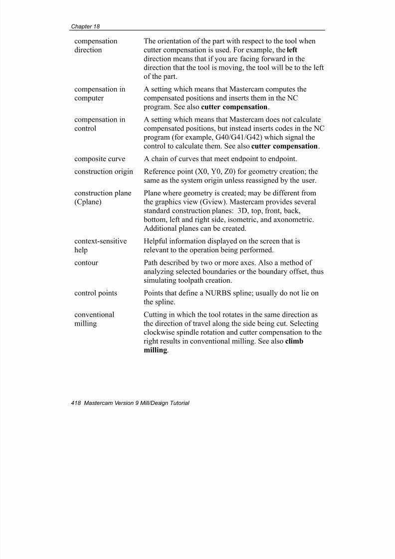
7/18/2019 V9 Mill-Design Tutorial (metric).pdf
http://slidepdf.com/reader/full/v9-mill-design-tutorial-metricpdf 430/453
Chapter 18
418 Mastercam Version 9 Mill/Design Tutorial
compensation
direction
The orientation of the part with respect to the tool when
cutter compensation is used. For example, the left
direction means that if you are facing forward in thedirection that the tool is moving, the tool will be to the left
of the part.
compensation in
computer
A setting which means that Mastercam computes the
compensated positions and inserts them in the NC program. See also cutter compensation.
compensation in
control
A setting which means that Mastercam does not calculate
compensated positions, but instead inserts codes in the NC
program (for example, G40/G41/G42) which signal thecontrol to calculate them. See also cutter compensation.
composite curve A chain of curves that meet endpoint to endpoint.
construction origin Reference point (X0, Y0, Z0) for geometry creation; the
same as the system origin unless reassigned by the user.
construction plane(Cplane) Plane where geometry is created; may be different fromthe graphics view (Gview). Mastercam provides several
standard construction planes: 3D, top, front, back,
bottom, left and right side, isometric, and axonometric.Additional planes can be created.
context-sensitive
help
Helpful information displayed on the screen that is
relevant to the operation being performed.
contour Path described by two or more axes. Also a method of
analyzing selected boundaries or the boundary offset, thussimulating toolpath creation.
control points Points that define a NURBS spline; usually do not lie onthe spline.
conventional
milling
Cutting in which the tool rotates in the same direction as
the direction of travel along the side being cut. Selectingclockwise spindle rotation and cutter compensation to the
right results in conventional milling. See also climb
milling.
7/18/2019 V9 Mill-Design Tutorial (metric).pdf
http://slidepdf.com/reader/full/v9-mill-design-tutorial-metricpdf 431/453
Glossary
Mastercam Version 9 Mill/Design Tutorial 419
converter A function that imports or exports files in different
formats. Formats that can be translated include ASCII,
CADL, DWG, DXF, IGES, NFL, Parasolid, SAT, STEP,STL, VDA, GEO, old GE3, as well as different versions
of Mastercam.
Coons patch A surface constructed by blending a grid of along curves
and across curves. Named after Steven A. Coons. See alsoCoons surface.
Coons surface A surface composed of one or more Coons patches.
coordinate The combination of an axis and a number which
represents a position along the axis, for example, X1. A pair of coordinates can represent a position in a plane, for
example X1,Y2. Three coordinates can represent a
position in 3-dimensional space, for example, X1,Y2,Z5.
copious data An entity type that represents a collection of geometricforms (points and lines). Copious data originates in an
IGES file. Mastercam can convert it to points and linesduring translation. The Modify, Break, Cdata/line function
can also be used to convert copious data to points andlines.
Cplane See construction plane.
critical depths Toolpath cut depths that must be machined even if depth
increments must be adjusted to cut them.
cross-section A section made by a plane cutting traversely throughsolids or surfaces. Also used in project toolpaths.
curvature (surface) Measure of curving of a curve or surface.
curve Line, arc, spline, or surface curve.
cut (toolpaths and
solids)
When used with respect to toolpaths, refers to tool
movement in the Z axis; do not confuse with pass.
When used with respect to solids, a type of solid operationin which chains of curves are extruded, revolved, swept,
or lofted as material is removed from an existing solid
(target body).
7/18/2019 V9 Mill-Design Tutorial (metric).pdf
http://slidepdf.com/reader/full/v9-mill-design-tutorial-metricpdf 432/453
Chapter 18
420 Mastercam Version 9 Mill/Design Tutorial
cutter compensation The process of offsetting a toolpath from the part
geometry by an amount typically equal to the radius of the
tool. See also compensation in computer and
compensation in control.
cutter offset Distance from the part surface to the axial tool center; tool
radius.
cutter path The path the center or tip of the tool follows over the part;the toolpath.
D
data bits A communications parameter that defines the number of
bits used to represent a character; must be the same for
both the PC and the CNC controller or peripheral device.
depth cuts Z-axis cuts that the tool makes in a contour, pocket, face,
circle mill, or surface toolpath to get to the final depth in
set increments.
DF9 Mastercam default parameter file format for Version 9(*.DF9); contains default values for all toolpath types.
dirty operation A solid or toolpath operation that has been modified in
some way; for example, its parameters or geometry input.
The system marks dirty solids and operations with a red‘X’ in the Solids Manager dialog box or Operations
Manager. When an operation is dirty, it must be
regenerated for the toolpath or geometry to match the
parameters.
display cues Features that clarify how geometry is oriented in the
graphics window: XYZ axes marker, dynamic arrow,surface backside display.
display list An internal feature that saves the display data for eachentity; used by Mastercam to determine what entities are
visible on the screen and to speed redraws, view changes,and other screen functions.
7/18/2019 V9 Mill-Design Tutorial (metric).pdf
http://slidepdf.com/reader/full/v9-mill-design-tutorial-metricpdf 433/453
Glossary
Mastercam Version 9 Mill/Design Tutorial 421
DNC Acronym for direct numerical control or distributive
numerical control. Direct numerical control uses a single
computer to simultaneously control operation of a groupof NC machines. Distributive numerical control uses a
network of computers to coordinate operation of a group
of CNC machine tools. Mastercam can be used in either
situation.dongle Another name for a SIM, which is required to run
Mastercam. See also HASP.
DOS (shell) Acronym for Disk Operating System. A DOS shell can be
used execute MS-DOS commands while Mastercam isrunning.
double D A shape composed of two line entities and two arc
entities.
dpi Dots per inch, a measure of graphic resolution.
drafting entity An entity used in dimensioning: witness lines, leaderlines, dimensions, cross hatches, labels, notes, copious
data. See also geometric entity.
drive surface A surface and/or solid body that undergoes a surface or
multiaxis machining operation. See also check surface.
dynamic arrow Cursor display that permits dynamic movement alonggeometry to indicate a position; changes size to indicate
orientation of arrow relative to viewer. When large, the
arrow points toward viewer. When small, the arrow pointsaway.
Eedge A topological element of a solid model, which has an
underlying curve.
edge profile Defines the shape of the surface outer boundaries.
edge tolerance The degree of precision with which edges of trimmedsurfaces are created.
editor An application used to modify files of certain types. Seealso MCEDIT, PFEDIT32, CNCEDIT.
7/18/2019 V9 Mill-Design Tutorial (metric).pdf
http://slidepdf.com/reader/full/v9-mill-design-tutorial-metricpdf 434/453
Chapter 18
422 Mastercam Version 9 Mill/Design Tutorial
ellipse An oval-shaped curve, represented by a NURBS spline or
collection of connected lines.
entity A design building block. There are geometric entities(points, lines, arcs, splines, surface curves, surfaces,
solids, copious data) and drafting entities (witness, lines,
leader lines, dimensions, crosshatches, labels, notes).
entity association The dependent relationship between one entity and asecond entity or group of entities from which the first
entity is generated.
EPS Acronym for Encapsulated PostScript. This is a common
vector graphics format.
F
feed plane Height that the tool moves to before changing from the
rapid rate to the plunge rate to enter the part.
feed rate Cutting tool speed of movement in the cutting direction;
usually expressed in inches per minute.
file information Displayed when an operator presses [F9]: file name and path, date and time of last file save, file size in bytes,
current display scale, relative positions of construction,
tool, and system origins and axes.
fillet An arc tangent to two non-tangent curves; a roundedinterior or exterior corner.
filter (Filter) The process of eliminating unnecessary tool movements
from a toolpath. Do not confuse with mask. When
capitalized, an utility that performs this function.finish Precision surface machining.
fit screen To display the visible geometry so as to fill as much of the
graphics window as possible; a Mastercam function that is
available from the right-click menu, by choosing from
the toolbar, or by pressing [Alt + F1].
flat boundary Used to create a flat, trimmed surface from one or more
closed sets of curves.
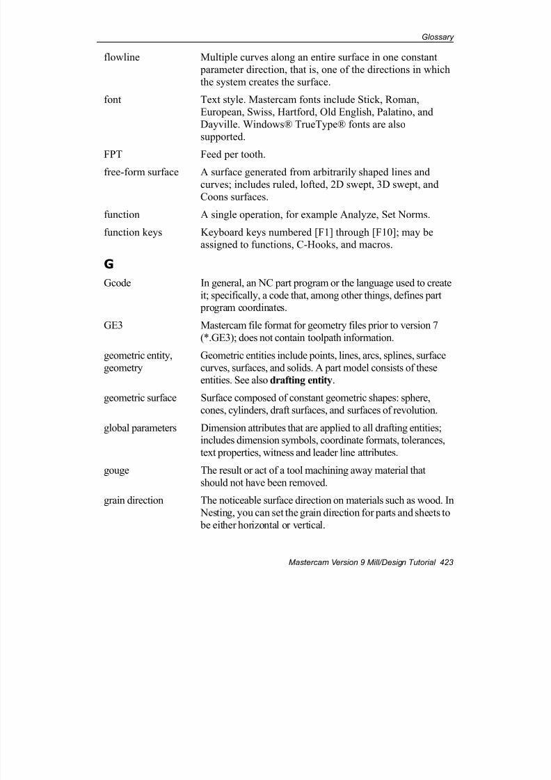
7/18/2019 V9 Mill-Design Tutorial (metric).pdf
http://slidepdf.com/reader/full/v9-mill-design-tutorial-metricpdf 435/453
Glossary
Mastercam Version 9 Mill/Design Tutorial 423
flowline Multiple curves along an entire surface in one constant
parameter direction, that is, one of the directions in which
the system creates the surface.
font Text style. Mastercam fonts include Stick, Roman,
European, Swiss, Hartford, Old English, Palatino, and
Dayville. Windows® TrueType® fonts are also
supported.
FPT Feed per tooth.
free-form surface A surface generated from arbitrarily shaped lines and
curves; includes ruled, lofted, 2D swept, 3D swept, and
Coons surfaces.
function A single operation, for example Analyze, Set Norms.
function keys Keyboard keys numbered [F1] through [F10]; may beassigned to functions, C-Hooks, and macros.
G
Gcode In general, an NC part program or the language used to create
it; specifically, a code that, among other things, defines part program coordinates.
GE3 Mastercam file format for geometry files prior to version 7
(*.GE3); does not contain toolpath information.
geometric entity,
geometry
Geometric entities include points, lines, arcs, splines, surface
curves, surfaces, and solids. A part model consists of theseentities. See also drafting entity.
geometric surface Surface composed of constant geometric shapes: sphere,
cones, cylinders, draft surfaces, and surfaces of revolution.
global parameters Dimension attributes that are applied to all drafting entities;includes dimension symbols, coordinate formats, tolerances,
text properties, witness and leader line attributes.
gouge The result or act of a tool machining away material that
should not have been removed.
grain direction The noticeable surface direction on materials such as wood. In
Nesting, you can set the grain direction for parts and sheets to
be either horizontal or vertical.
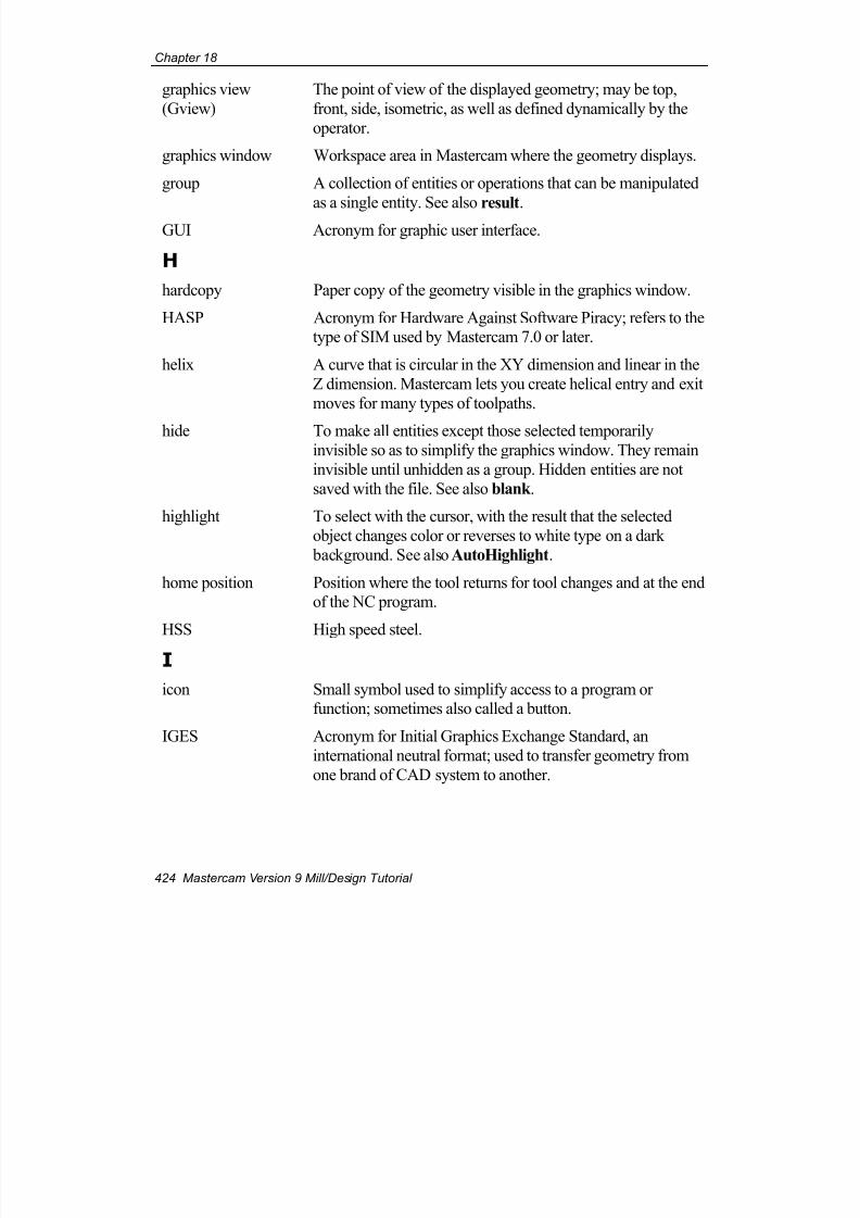
7/18/2019 V9 Mill-Design Tutorial (metric).pdf
http://slidepdf.com/reader/full/v9-mill-design-tutorial-metricpdf 436/453
Chapter 18
424 Mastercam Version 9 Mill/Design Tutorial
graphics view
(Gview)
The point of view of the displayed geometry; may be top,
front, side, isometric, as well as defined dynamically by the
operator.
graphics window Workspace area in Mastercam where the geometry displays.
group A collection of entities or operations that can be manipulated
as a single entity. See also result.
GUI Acronym for graphic user interface.
H
hardcopy Paper copy of the geometry visible in the graphics window.
HASP Acronym for Hardware Against Software Piracy; refers to thetype of SIM used by Mastercam 7.0 or later.
helix A curve that is circular in the XY dimension and linear in the
Z dimension. Mastercam lets you create helical entry and exit
moves for many types of toolpaths.
hide To make all entities except those selected temporarilyinvisible so as to simplify the graphics window. They remain
invisible until unhidden as a group. Hidden entities are not
saved with the file. See also blank .
highlight To select with the cursor, with the result that the selected
object changes color or reverses to white type on a dark
background. See also AutoHighlight.
home position Position where the tool returns for tool changes and at the endof the NC program.
HSS High speed steel.
I
icon Small symbol used to simplify access to a program orfunction; sometimes also called a button.
IGES Acronym for Initial Graphics Exchange Standard, an
international neutral format; used to transfer geometry from
one brand of CAD system to another.

7/18/2019 V9 Mill-Design Tutorial (metric).pdf
http://slidepdf.com/reader/full/v9-mill-design-tutorial-metricpdf 437/453
Glossary
Mastercam Version 9 Mill/Design Tutorial 425
incremental
(coordinates,
dimensioning, positioning)
Measured from the immediately preceding point.
infinite look ahead In contour analysis, to search the entire boundary to find self-
intersections based on the current offset distance and cutter
compensation.
integer A whole number such as 3, 50, or 764; used as a data type for
counting or numbering.
J
job Contains a set of operations.
Job Setup Machining job parameters, including stock setup, NCIconfiguration, material selection, and tool offsets.
jump height
command
Allows a tool to be moved to a height above the clearance
plane between points in a toolpath.
L
level A grouping used to organize geometry in Mastercam.
level report A report of what entities exist on each level of a geometry file.
line Straight entity between two endpoints.
line style The appearance of a line; may be solid, hidden, center,
phantom, or Zbreak.
linear array A repeating toolpath along the X or Y axis of the construction plane at a specific distance.
linearization
tolerance
Used when converting 3D arcs and 2D or 3D splines in the
chained geometry from curves to lines; represents the
maximum distance between an arc or spline and its linearapproximation.
loft surface A surface composed of smoothly blended curves created by
fitting through a set of cross-sectional curves.
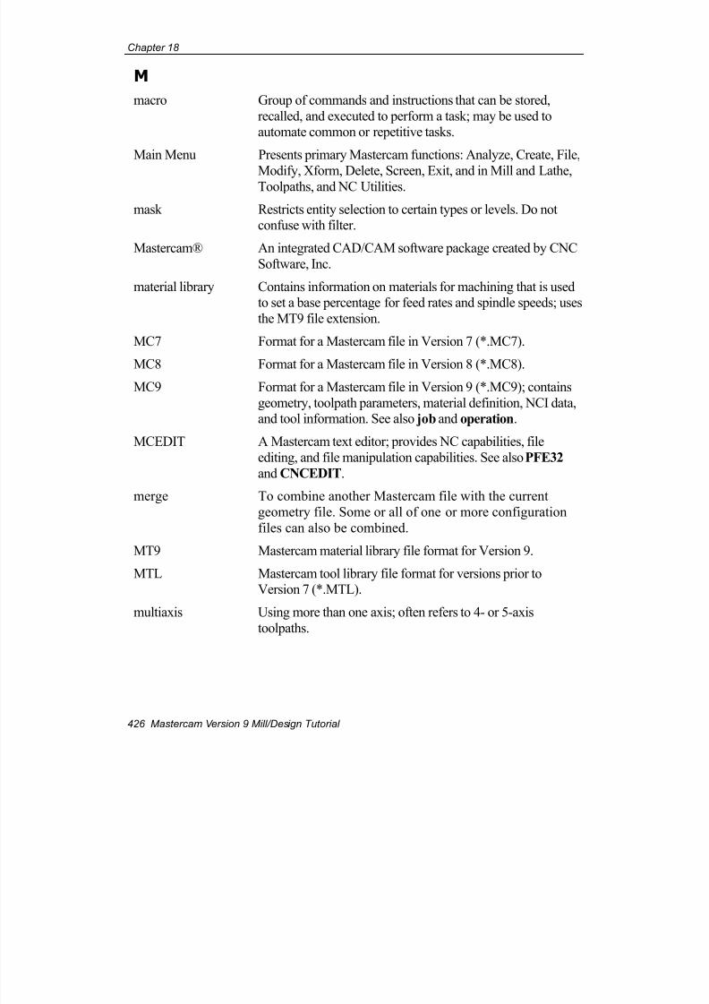
7/18/2019 V9 Mill-Design Tutorial (metric).pdf
http://slidepdf.com/reader/full/v9-mill-design-tutorial-metricpdf 438/453
Chapter 18
426 Mastercam Version 9 Mill/Design Tutorial
M
macro Group of commands and instructions that can be stored,
recalled, and executed to perform a task; may be used toautomate common or repetitive tasks.
Main Menu Presents primary Mastercam functions: Analyze, Create, File,
Modify, Xform, Delete, Screen, Exit, and in Mill and Lathe,Toolpaths, and NC Utilities.
mask Restricts entity selection to certain types or levels. Do notconfuse with filter.
Mastercam® An integrated CAD/CAM software package created by CNC
Software, Inc.
material library Contains information on materials for machining that is usedto set a base percentage for feed rates and spindle speeds; uses
the MT9 file extension.
MC7 Format for a Mastercam file in Version 7 (*.MC7).
MC8 Format for a Mastercam file in Version 8 (*.MC8).
MC9 Format for a Mastercam file in Version 9 (*.MC9); contains
geometry, toolpath parameters, material definition, NCI data,and tool information. See also job and operation.
MCEDIT A Mastercam text editor; provides NC capabilities, file
editing, and file manipulation capabilities. See also PFE32
and CNCEDIT.
merge To combine another Mastercam file with the current
geometry file. Some or all of one or more configuration
files can also be combined.
MT9 Mastercam material library file format for Version 9.
MTL Mastercam tool library file format for versions prior toVersion 7 (*.MTL).
multiaxis Using more than one axis; often refers to 4- or 5-axis
toolpaths.
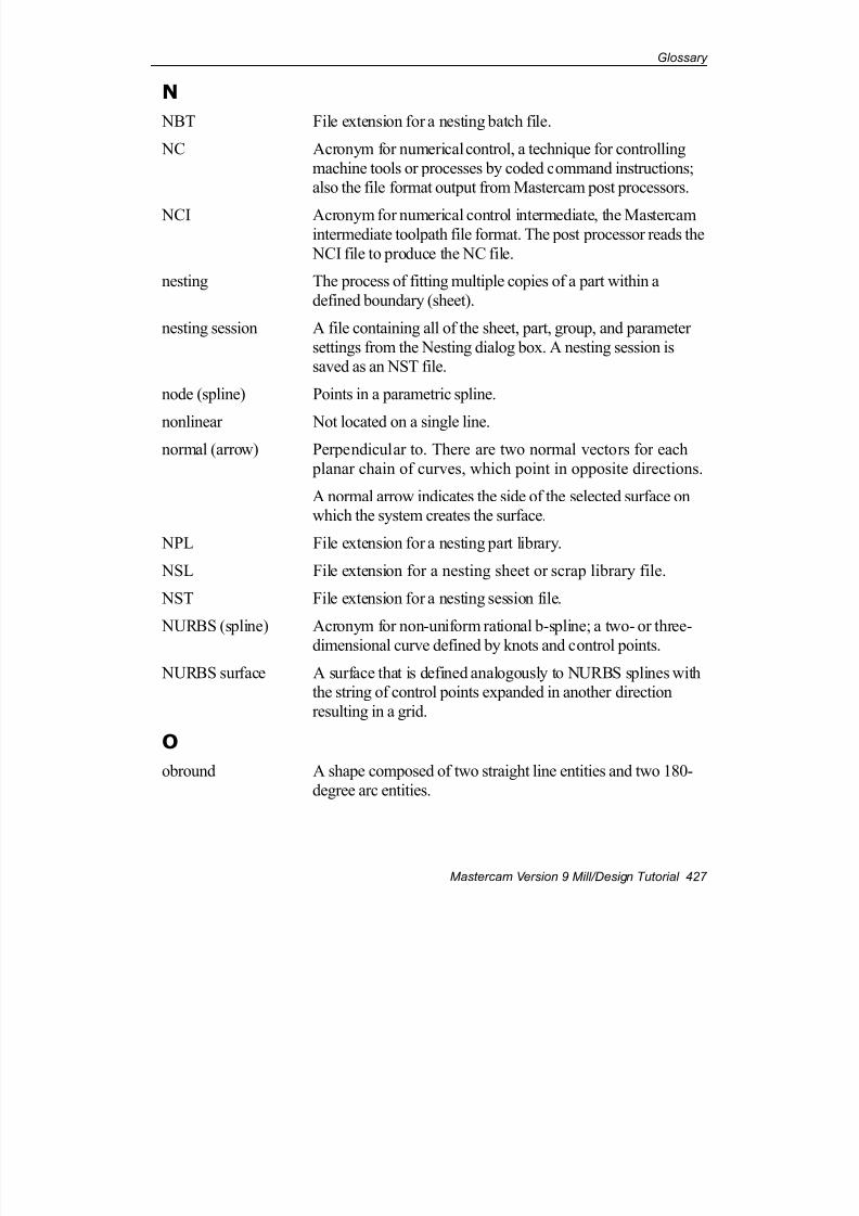
7/18/2019 V9 Mill-Design Tutorial (metric).pdf
http://slidepdf.com/reader/full/v9-mill-design-tutorial-metricpdf 439/453
Glossary
Mastercam Version 9 Mill/Design Tutorial 427
N
NBT File extension for a nesting batch file.
NC Acronym for numerical control, a technique for controlling
machine tools or processes by coded command instructions;also the file format output from Mastercam post processors.
NCI Acronym for numerical control intermediate, the Mastercamintermediate toolpath file format. The post processor reads the
NCI file to produce the NC file.
nesting The process of fitting multiple copies of a part within a
defined boundary (sheet).
nesting session A file containing all of the sheet, part, group, and parameter
settings from the Nesting dialog box. A nesting session issaved as an NST file.
node (spline) Points in a parametric spline.
nonlinear Not located on a single line.normal (arrow) Perpendicular to. There are two normal vectors for each
planar chain of curves, which point in opposite directions.
A normal arrow indicates the side of the selected surface onwhich the system creates the surface.
NPL File extension for a nesting part library.
NSL File extension for a nesting sheet or scrap library file.
NST File extension for a nesting session file.
NURBS (spline) Acronym for non-uniform rational b-spline; a two- or three-
dimensional curve defined by knots and control points.
NURBS surface A surface that is defined analogously to NURBS splines withthe string of control points expanded in another direction
resulting in a grid.
O
obround A shape composed of two straight line entities and two 180-
degree arc entities.
7/18/2019 V9 Mill-Design Tutorial (metric).pdf
http://slidepdf.com/reader/full/v9-mill-design-tutorial-metricpdf 440/453
Chapter 18
428 Mastercam Version 9 Mill/Design Tutorial
offset To displace an entity or chain by a distance in a perpendicular
direction relative to the current construction plane. In a curve,
displacement is perpendicular to the direction vector at everylocation on the curve.
offset surface A surface created by offsetting an existing surface by a
distance.
OP9 Mastercam operation library file format for Version 9.
open chain A chain whose first and last endpoints are not identical, suchas a line.
OpenGL® An operating system-independent standard for displaying
graphics.
operation (toolpaths
and solids)
When used with respect to toolpaths, consists of geometry,
toolpath (NCI file), tool definition, and parameters. A set ofoperations makes up a job or MC9 file. Each operation
includes only one toolpath. See also job and MC9.
When used with respect to solids, the action or actions performed to create or modify a solid. Each operation, such asfillet or extrude, is listed separately in the history tree under
the solid that it defines or modifies.
operation library Contains default parameters for a specific toolpath; can be
applied to current geometry; uses the OP9 file extension.
Operations Manager Lists all operations in the current Mastercam file, including
both associative and non-associative toolpaths, and offers
options for managing them.
origin Intersection point of coordinate axes: typically, the pointX0Y0, or X0Y0Z0. See also system origin, construction
origin, and tool origin.
P
pan To move geometry within the graphics window. You can
press the arrow keys, or right-click in the graphics windowand choose Dynamic pan from the menu.
parallel views Construction planes that exist in the same 2D plane but differ by rotation or position.
7/18/2019 V9 Mill-Design Tutorial (metric).pdf
http://slidepdf.com/reader/full/v9-mill-design-tutorial-metricpdf 441/453
Glossary
Mastercam Version 9 Mill/Design Tutorial 429
parametric spline A 2D or 3D curve defined by a set of coefficients or nodes.
parametric surface A surface composed of parametric splines in which each
curve segment is expanded in another direction resulting in a patch.
part The item to be machined or nested.
part drawing Describes the shape and size of a part; usually includes partfeatures, dimensions, tolerances, and surface roughness.
part feature The distinctive shape and size to be produced in a part; can be
2D (flat surfaces, internal and external profiles, pockets, holes,etc.) or 3D (surfaces).
part library In Nesting, a file containing part definitions so that they can
be reused. A part library is saved as an NPL file.
pass A tool movement in the X and Y axes. Do not confuse withcut.
patch Area of a surface bounded by four segments of the generating
curves.
peck A tool move that occurs at the programmed feed rate as it
feeds into and retracts out of the stock during a drill toolpath.
peck clearance Depth that the tool rapids down to between peck movementsduring a drill toolpath.
PFE32 A Mastercam text editor; provides file editing and
manipulation capabilities.
planar Flat, lying within a single geometric plane.
plot To output current graphics window to a plotter or file. point (entity) Entity that marks a position in 2D or 3D space but that has no
dimension.
point (using the
mouse)
To move the mouse until the mouse pointer on the screen
rests on the item you want.
point data Data consisting only of points.
7/18/2019 V9 Mill-Design Tutorial (metric).pdf
http://slidepdf.com/reader/full/v9-mill-design-tutorial-metricpdf 442/453
Chapter 18
430 Mastercam Version 9 Mill/Design Tutorial
polar (coordinates
and dimension)
Coordinate system that uses a known point, length (radius),
and angle to locate a point in space. The angle is calculated in
a counterclockwise direction from the positive horizontal axisthat runs through the known point in the current construction
plane.
polygon Irregular, closed shape with three or more straight sides. In
Mastercam, can be created as a single NURBS spline or as acollection of individual lines.
port A physical connection on a PC. Serial ports are used to
connect to the CNC controller and are identified as COM1,
COM2, etc.
post Post processor. Also a post processor (PST) file.
post processor A program that translates NCI data to a format usable by a
machine, that is, to an NC part program or Gcode.
primitive A surface or solid created using a predefined shape, such as a
block or sphere. The parameters can be changed interactively, but it maintains its original shape. A primitive surface or solid
is not defined by curve geometry. Mastercam primitives
include cylinder, cone, block, extrusion (surfaces only),sphere, and torus.
PRM Mastercam default parameter file format and file extension for
versions prior to Version 7.
prompt area A two- or four-line area at the bottom of the Mastercam
interface used to display data or enter values with thekeyboard.
PST File format for a post processor customization file.
Q
quadrant A section of a plane in which quadrant 1 lies between 0 and
90 degrees, quadrant 2 lies between 90 and 180 degrees,quadrant 3 lies between 180 and 270 degrees, and quadrant 4
lies between 270 and 360 degrees.
R
RAM Acronym for random-access memory.

7/18/2019 V9 Mill-Design Tutorial (metric).pdf
http://slidepdf.com/reader/full/v9-mill-design-tutorial-metricpdf 443/453
Glossary
Mastercam Version 9 Mill/Design Tutorial 431
RAM-saver An option that compacts the system database and frees up
available RAM; can also perform an efficiency and integrity
check on the database.
real number A number that can be represented by digits in a
numbering system with a fixed base, such as 0.5 or 25.4;
used for storing measurements and other values to some
limit of precision.
raster A method of generating graphics in which images are
stored as many small, independently controlled dots
(pixels).
rectangle A shape which consists of four straight lines and four rightangles.
Rectangular nesting A nesting method which treats each sheet and part as if it were
contained in a rectangular bounding box.
redraw To erase then redisplay visible geometry in the graphics
window to clean up display remnants.reference point Point to which the tool moves before reentering a toolpath.
regenerate In general, to recompute solids, drafting entities, or toolpaths
when associated geometry or parameters have been changed.
To rebuild the graphics window display list so as to improve
the speed and results. The Regen path option in theOperations Manager recomputes a toolpath when the
associated geometry or parameters have been modified.
relative (coordinates,
dimensioning, and
positioning)
Distance measured from specific point, not necessarily the
zero or preceding point.
remachine A machining operation used to clean up stock leftover from
one or more previous operations. Remachining operations
calculate the amount of leftover stock and use that as thestarting point for the toolpath motions. See also restmill.
repaint To erase then redisplay the visible geometry in the graphics
window to clean up display remnants.
required pilotdiameter
Minimum diameter necessary for the tool to enter thetoolpath.
7/18/2019 V9 Mill-Design Tutorial (metric).pdf
http://slidepdf.com/reader/full/v9-mill-design-tutorial-metricpdf 444/453
Chapter 18
432 Mastercam Version 9 Mill/Design Tutorial
rest material The leftover stock that forms the basis for a restmill toolpath.
Mastercam computes this by looking at one or more
operations that you select, or from the dimensions of aroughing tool that you supply. See also restmill.
restmill A type of remachining toolpath used for roughing, in which
the tool uses multiple depth cuts to remove stock leftover
from one or previous operations. See also remachine, restmaterial.
result The appearance of an entity group that has been transformed;
may be selected for further transformation or translation. The
default color of a result is purple.
retract amount Distance that the drill retracts every time it makes a peck
move during a drill toolpath.
retract height The height to which the tool moves before the next tool pass.
revolved surface A surface created by rotating a sectional shape around an axis
or line.right-click To click on something using the right mouse button; displays
alternate (right-click) menus.
right-click menu A menu that opens when you right-click the mouse; gives
quick access to many common features.
roll To wrap a line, arc, or spline around a cylinder.
rough To remove large amounts of material as rapidly as possible.
RPM Revolutions per minute; a measure of spindle speed.
rubber-band Temporary display of entities that will be created or modified;
the display updates dynamically based on the cursor locationto indicate the result with the cursor at that location.
ruled surface A surface composed of linearly blended curves created by
connecting straight lines between two or more lines or curves.
S
save some To save selected entities to an MC9 file. Toolpaths cannot besaved using this method.

7/18/2019 V9 Mill-Design Tutorial (metric).pdf
http://slidepdf.com/reader/full/v9-mill-design-tutorial-metricpdf 445/453
Glossary
Mastercam Version 9 Mill/Design Tutorial 433
scale To increase or decrease the size of an entity by a factor
relative to the construction origin or some other point. Also
see scaleXYZ.
scaleXYZ To increase or decrease the size of an entity independently in
X, Y, and Z dimensions. Also see scale.
scrap Material remaining from a sheet used in a previous nestingsession.
scrap library A file containing scrap definitions so that they can be reused.
A scrap library is saved as an NSL file.
Screen, Configure A menu that sets Mastercam’s default values. Default
configuration files are MILL9.CFG (English units) andMILL9M.CFG (metric units).
segment A section of a spline between two nodes
selection cues In Mastercam, functions such as AutoHighlight, AutoCursor,
etc., which help you determine what entities you can select.
selection grid A grid of reference points that the cursor can snap to duringsketching.
setup sheet A file created by Mastercam that contains NCI file
information including operation, tool reference, total
programming time, and text entered manually during programming; uses the SET extension.
SFM Acronym for surface feet per minute.
shading Representation of light striking a colored surface or solid
object using gradated fill.
sheet The closed boundary that defines the material on which
nested parts are placed.
sheet library A file containing sheet definitions so that they can be reused.A sheet library is saved as an NSL file.
7/18/2019 V9 Mill-Design Tutorial (metric).pdf
http://slidepdf.com/reader/full/v9-mill-design-tutorial-metricpdf 446/453
Chapter 18
434 Mastercam Version 9 Mill/Design Tutorial
shortcuts In Mastercam, a way of gathering data from the graphics
window. Allows you to modify data collected from the
graphics window by entering values in the prompt area.Shortcuts appear in the prompt area as X, Y, Z, R(adius),
D(iameter), L(ine length), S(distance between two points),
and A(ngle).
SIM Acronym for Software Interface Module; sometimes called adongle; required to run Mastercam.
single D A shape composed of one line entity and one arc entity.
sketch To create geometry or select entities by identifying points in
the graphics window using the cursor and mouse.
slice The process of creating points at the intersection of lines, arcs,and splines with a plane and creating points where they
intersect. Also the process of creating curves at the
intersection of surfaces and solids with a plane and creatingcurves where they intersect.
solid A geometric representation of a closed three-dimensional
object. In Mastercam, a solid is a geometric entity that differs
from other types of geometric entities such as lines, arcs,splines in that each solid is also a topological entity that
occupies a region of space and that consists of one or more
faces, which define the closed boundary of the solid.
spindle speed Tool rotation speed (RPM)
spline Smooth, free-form curve controlled by points including thecondition of its endpoints; may be parametric or NURBS
spline.
startup file Configuration file, which contains Mastercam default values.
statistics (screen) Tally of visible entities by type.
step angle Controls the degree of rotation Nesting can use when fitting parts on a sheet. For example, a 90 degree step angle allows
Nesting to use 90, 180, and 270 degree rotations. A smaller
step angle increases the amount of time needed to generate the
nesting results because Nesting makes more attempts at fittingthe part more precisely.
7/18/2019 V9 Mill-Design Tutorial (metric).pdf
http://slidepdf.com/reader/full/v9-mill-design-tutorial-metricpdf 447/453
Glossary
Mastercam Version 9 Mill/Design Tutorial 435
stepdown The distance that separates adjacent cuts in the Z axis on a
surface toolpath.
stepover The distance that separates adjacent cuts in the XY plane on asurface toolpath.
stretch To place around geometry a window that intersects other
geometry, then to translate the entities that are completely
inside the window and also lengthen or shorten any lines thatcross the window (by translating the endpoint that is inside the
window).
style/width Line style and width used to display lines, arcs, and splines.
subprogram A section of the NCI file that repeats at different locations.
supplementary angle An angle that when added to another angle produces an angle
of 180 degrees.
surface A representation of a part’s skin by mathematical equations; a
boundary defining an exterior face of a solid model.
surface curve A curve entity type created directly on a surface through the
Create Curve function.
surface memoryallocation
The amount of RAM allocated for surface generation.
surface model Defines a surface, including the edges of each surface.
surface normal Vector perpendicular to tangent plane of surface.
surface projection Creates points (or curves) by projecting selected points (or
curves) onto selected surfaces.
surface shading Color fill added to surfaces and solids to make them moreeasily visible; may be full-time or studio.
surface types Mastercam supports three surface types based on
mathematical generation methods: parametric, NURBS, and
curve-generated. Surfaces may also be typed by componentsand application into loft, ruled, Coons, revolved, swept, draft,
fillet, offset, trim/extend, and blend surfaces.
7/18/2019 V9 Mill-Design Tutorial (metric).pdf
http://slidepdf.com/reader/full/v9-mill-design-tutorial-metricpdf 448/453
Chapter 18
436 Mastercam Version 9 Mill/Design Tutorial
swept surface Created by sweeping one or two curves or chains of curves
(across curves) through a trajectory of one or two other curves
or chains of curves (along curves); may be 2D or 3D. Alsocalled a drag surface.
swept toolpath Created by sweeping one chains of curves (the across chain)
along a second chain (the along chain).
Sync A function that breaks a chain into separate sections, each beginning and ending at a specified point, then matches it
with one or more other chains with the same number of
synchronization points.
system origin Fixed reference point for all geometry creation (X0, Y0, Z0).
system tolerance Maximum distance between two points that can still beconsidered coincident.
T
tangent Two curves whose slope is continuous in direction across
their common endpoint.
tip comp Cutter compensation calculated to the tool center or tip.
TL9 Mastercam tool library file format for Version 9.
tolerance The precision with which an entity must fit another entity or
process, or the maximum permissible deviation from a value;includes system, chaining, minimum arc length, curve
minimum step size, curve maximum step size, curve chordal
deviation, and maximum surface deviation tolerances.
Tolerance dimension format is one of the global drafting parameters.
tool The cutting or machining part, usually removable, of a lathe,
planer, drill, or similar machine.

7/18/2019 V9 Mill-Design Tutorial (metric).pdf
http://slidepdf.com/reader/full/v9-mill-design-tutorial-metricpdf 449/453
Glossary
Mastercam Version 9 Mill/Design Tutorial 437
tool body The body or bodies that are added to, removed from, or used
to keep a common region with a selected target body during a
Boolean operation. Once a solid is designated a tool body, it becomes part of the target body. In the Solids Manager dialog
box, a tool body is listed under the solid and Boolean
operation that it helps to define, and its icon is marked with
the letter ‘T’. Note: When you delete a Boolean operation, the system
restores the operation’s tool bodies as distinct, active solids.
You can also duplicate a tool body to obtain an active copy ofthe solid.
tool center boundary A closed set of curves that limits tool movement for a surface
toolpath. The tool’s center stays within the selected boundary.
tool library Contains information on multiple mill and lathe tools, such as
spindle speeds, plunge rates, and tool diameters; uses the TL9file extension.
Tools Manager A Mastercam function that provides a list of tools stored inthe current job or in the current tool library; also allows
management of tool libraries.
tool origin The reference point (X0, Y0, Z0) in the tool plane (Tplane);
the same as the system origin unless reassigned by the user.
tool plane (Tplane) A 2D plane that represents the CNC machine’s XY axis and
origin; also called Tplane.
toolbar Area on the screen that contains icons (buttons). The buttonsare arranged in pages to which the user can scroll; may be
moved and reassigned.
toolpath Shows where a tool removes material from a part.
Tplane See tool plane.
transform To translate, mirror, rotate, scale, offset stretch, or rollgeometry or toolpaths.
translate To move or copy geometry or toolpaths to a new location
without changing orientation. Also see transform.
trim To act as a boundary for a entity or surface.
7/18/2019 V9 Mill-Design Tutorial (metric).pdf
http://slidepdf.com/reader/full/v9-mill-design-tutorial-metricpdf 450/453
Chapter 18
438 Mastercam Version 9 Mill/Design Tutorial
trim/extend surface A surface created by trimming or extending existing surfaces.
trimmed surface Surface bounded at a set of edges; can be created by applying
any or a number of processes to untrimmed or trimmedsurfaces, for example, projection of curves, intersection, or
filleting with other surfaces.
trochoidal A type of loop used in highspeed toolpaths in which a
continuous loop is overlayed on top of a toolpath, and the toolmoves along the path of the loop.
TrueShape nesting A nesting method that fits parts on a sheet based on each part's
actual shape and other parameters. It also allows access to
sheet and part libraries and extended functionality beyondRectangular nesting. TrueShape nesting increases the yield of
parts from a sheet of material.
U
undo To reverse the last action performed.
unwrap To unroll a rolled entity.
unzoom To return to the previous display scale or to the originaldisplay size.
unzoom by 0.8 To return to the previous display scale or reduce the size of
the displayed geometry to 80% of its original size.
V
vector (1) A graphics file format in which graphics are stored as
lines and curves, instead of dots or pixels. Common file
extensions are EPS and AI. See also bitmap, raster.
vector (2) A directed line segment.
vertex An endpoint of an edge.
view Angle of observing the geometry – top, front, back, bottom,
right side, left side, Cplane, isometric, or axonometric.
viewport Area within the graphics window that displays the geometry.
W
WCS See work coordinate system.
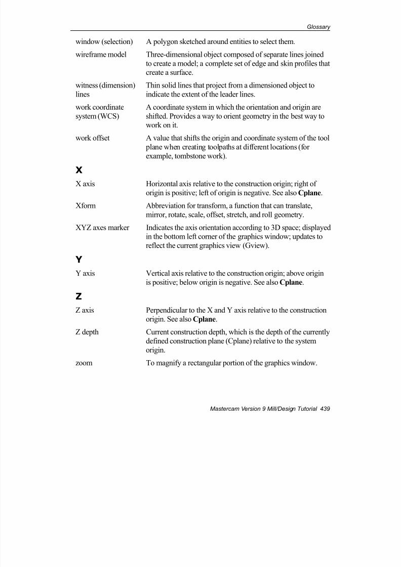
7/18/2019 V9 Mill-Design Tutorial (metric).pdf
http://slidepdf.com/reader/full/v9-mill-design-tutorial-metricpdf 451/453
Glossary
Mastercam Version 9 Mill/Design Tutorial 439
window (selection) A polygon sketched around entities to select them.
wireframe model Three-dimensional object composed of separate lines joined
to create a model; a complete set of edge and skin profiles thatcreate a surface.
witness (dimension)
lines
Thin solid lines that project from a dimensioned object to
indicate the extent of the leader lines.
work coordinate
system (WCS)
A coordinate system in which the orientation and origin are
shifted. Provides a way to orient geometry in the best way towork on it.
work offset A value that shifts the origin and coordinate system of the tool
plane when creating toolpaths at different locations (for
example, tombstone work).
X
X axis Horizontal axis relative to the construction origin; right of
origin is positive; left of origin is negative. See also Cplane.
Xform Abbreviation for transform, a function that can translate,
mirror, rotate, scale, offset, stretch, and roll geometry.
XYZ axes marker Indicates the axis orientation according to 3D space; displayedin the bottom left corner of the graphics window; updates to
reflect the current graphics view (Gview).
Y
Y axis Vertical axis relative to the construction origin; above origin
is positive; below origin is negative. See also Cplane.
ZZ axis Perpendicular to the X and Y axis relative to the construction
origin. See also Cplane.
Z depth Current construction depth, which is the depth of the currently
defined construction plane (Cplane) relative to the system
origin.
zoom To magnify a rectangular portion of the graphics window.

7/18/2019 V9 Mill-Design Tutorial (metric).pdf
http://slidepdf.com/reader/full/v9-mill-design-tutorial-metricpdf 452/453
Chapter 18
440 Mastercam Version 9 Mill/Design Tutorial
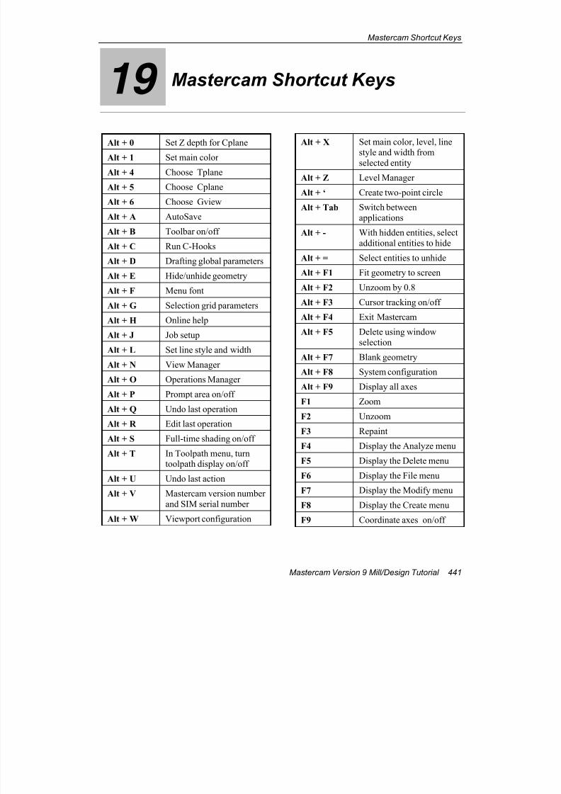
7/18/2019 V9 Mill-Design Tutorial (metric).pdf
http://slidepdf.com/reader/full/v9-mill-design-tutorial-metricpdf 453/453
Mastercam Shortcut Keys
19 Mastercam Shortcut Keys
Alt + 0 Set Z depth for Cplane
Alt + 1 Set main color
Alt + 4 Choose Tplane
Alt + 5 Choose Cplane
Alt + 6 Choose Gview
Alt + A AutoSave
Alt + B Toolbar on/off
Alt + C Run C-Hooks
Alt + D Drafting global parameters
Alt + E Hide/unhide geometryAlt + F Menu font
Alt + G Selection grid parameters
Alt + H Online help
Alt + J Job setup
Alt + L Set line style and width
Alt + N View Manager
Alt + O Operations Manager
Alt + P Prompt area on/off
Alt + Q Undo last operation
Alt + R Edit last operation
Alt + X Set main color, level, linestyle and width from
selected entity
Alt + Z Level Manager
Alt + ‘ Create two-point circle
Alt + Tab Switch between
applications
Alt + - With hidden entities, select
additional entities to hide
Alt + = Select entities to unhide
Alt + F1 Fit geometry to screen
Alt + F2 Unzoom by 0.8
Alt + F3 Cursor tracking on/off
Alt + F4 Exit Mastercam
Alt + F5 Delete using window
selection
Alt + F7 Blank geometry
Alt + F8 System configuration
Alt + F9 Display all axes
F1 Zoom
F2 Unzoom


![V9 series Troubleshooting / Maintenance Manual...V9 Series Reference Manual [1] Explains the functions and operation of the V9 series. 1065NE V9 Series Reference Manual [2] 1066NE](https://img.pdfslide.us/doc/110x75/5fdc0f46901d8161831e54dd/v9-series-troubleshooting-maintenance-v9-series-reference-manual-1-explains.jpg)