Embed Size (px)
Citation preview
V800/OE581/OE581M/Miniv581 CAN OBDII
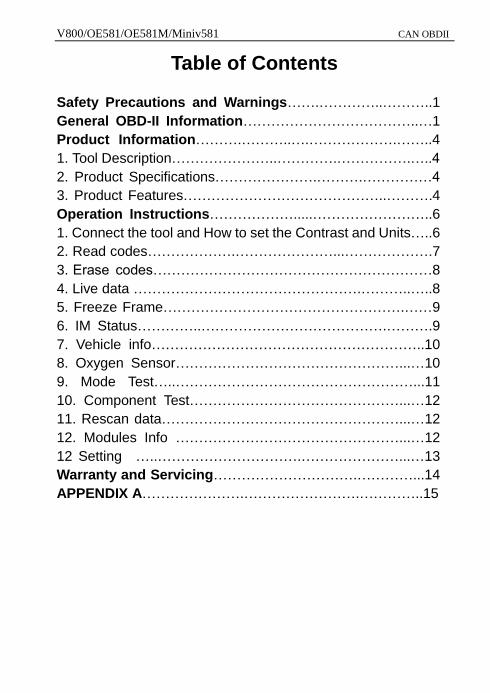
Table of Contents
Safety Precautions and Warnings…….…………..………..1
General OBD-II Information………………………………..…1
Product Information……….………..….……………….……..4
1. Tool Description…………………..………….…………….…..4
2. Product Specifications………………….……….……………4
3. Product Features……………………………………..……….4
Operation Instructions……………….....……………………..6
1. Connect the tool and How to set the Contrast and Units…..6
2. Read codes……………….…………………...……………….7
3. Erase codes……………………………………………………8
4. Live data ………………………………………….………..…..8
5. Freeze Frame…………………………………………….……9
6. IM Status…………..………………………………….……….9
7. Vehicle info…………………………………………………..10
8. Oxygen Sensor…………………………………………...…10
9. Mode Test…..……………………………………………...11
10. Component Test………………………………………...…12
11. Rescan data……………………………………………...…12
12. Modules Info …………………………………………...…12
12 Setting …..………………………….…………………...…13
Warranty and Servicing………………………….…………...14
APPENDIX A………………….…………………….…………..15
V800/OE581/OE581M/Miniv581 CAN OBDII
1
To prevent personal injury or damage to vehicles or the Car Tool, read this instruction manual first and observe the following safety precautions. 1. When an engine is running, it produces carbon monoxide, a toxic and poisonous gas. To prevent
serious injury or death from carbon monoxide poisoning ,operate the vehicle ONLY in a well-ventilated area.
2. To protect your eyes from propelled objects as well as hot or caustic liquids, always wear approved safety eye protection.
3. Keep cigarettes, sparks, open flame and other sources of ignition away from vehicle. Keep a dry chemical (Class B) fire extinguisher rated for gasoline, chemical and electrical fires in work area.
4. .Connecting or disconnecting test equipment when the ignition is ON can damage test equipment and the ignition OFF before connecting the Code Reader to or disconnecting the Code Reader from the vehicle’s Data Link Connector(DLC).
5. To prevent damage to the on-board computer when taking vehicle electrical measurements. always use a digital multi meter with at least 10megOhms of impedance.
6. Keep the car ToFol clean, dry and free from oil, water and grease. Use a mild detergent on a clean cloth to clean the outside of the Scan Tool, when necessary.
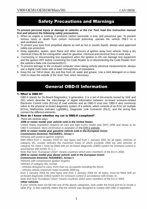
1. What is OBD-II?
OBD-II stands for On-Board Diagnostics, II generation. It is a set of documents issued by SAE and ISO, which describe the interchange of digital information between on-board emission-related Electronic Control Units (ECUs) of road vehicles and an OBD-II scan tool. OBD-II also commonly refers to the physical on-board diagnostic system of a vehicle, which consists of an ECU (or multiple ECUs), Malfunction Indicator Light(MIL), Diagnostic Link Connector (DLC), and the wiring that connect the different elements.
2. How do I know whether my car is OBD-II compliant?
There are several ways. 1996 or newer model year vehicle sold in the United States United States legislation requires all cars and light trucks model year (MY) 1996 and newer to be OBD-II compliant. More information is available on the EPA's website. 2001 or newer model year gasoline vehicle sold in the European Union Commission Directive 70/220/EEC, Annex I: Vehicles with positive-ignition engines With effect from 1 January 2000 for new types and from 1 January 2001 for all types, vehicles of category M1, except vehicles the maximum mass of which exceeds 2500 kg, and vehicles of category N1 class I, must be fitted with an on-board diagnostic (OBD) system for emission control in accordance with Annex XI. [...] Note that here "European Union" means countries which were members of the EU in 2000. 2004 or newer model year diesel vehicle sold in the European Union Commission Directive 70/220/EEC, Annex I: Vehicles with compression-ignition engines Vehicles of category M1, except - vehicles designed to carry more than six occupants including the driver, - vehicles whose maximum mass exceeds 2500 kg, from 1 January 2003 for new types and from 1 January 2004 for all types, must be fitted with an on-board diagnostic (OBD) system for emission control in accordance with Annex XI. Note that here "European Union" means countries which were members of the EU in 2003. Other vehicles If your vehicle does not fall into any of the above categories, look under the hood and try to locate a label (Fig. 1) that explicitly states that the vehicle was designed to comply with OBD-II legislation.
Safety Precautions and Warnings
General OBD-II Information
V800/OE581/OE581M/Miniv581 CAN OBDII
2
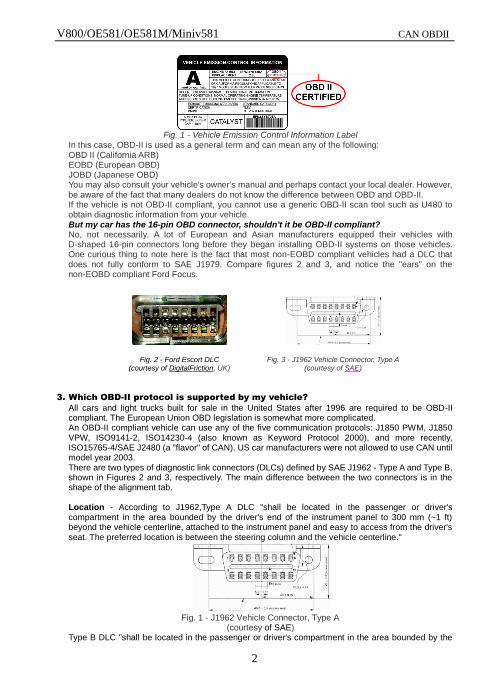
Fig. 1 - Vehicle Emission Control Information Label
In this case, OBD-II is used as a general term and can mean any of the following: OBD II (California ARB) EOBD (European OBD) JOBD (Japanese OBD) You may also consult your vehicle's owner's manual and perhaps contact your local dealer. However, be aware of the fact that many dealers do not know the difference between OBD and OBD-II. If the vehicle is not OBD-II compliant, you cannot use a generic OBD-II scan tool such as U480 to obtain diagnostic information from your vehicle. But my car has the 16-pin OBD connector, shouldn't it be OBD-II compliant? No, not necessarily. A lot of European and Asian manufacturers equipped their vehicles with D-shaped 16-pin connectors long before they began installing OBD-II systems on those vehicles. One curious thing to note here is the fact that most non-EOBD compliant vehicles had a DLC that does not fully conform to SAE J1979. Compare figures 2 and 3, and notice the "ears" on the non-EOBD compliant Ford Focus.
Fig. 2 - Ford Escort DLC (courtesy of DigitalFriction, UK)
Fig. 3 - J1962 Vehicle Connector, Type A (courtesy of SAE)
3. Which OBD-II protocol is supported by my vehicle?
All cars and light trucks built for sale in the United States after 1996 are required to be OBD-II compliant. The European Union OBD legislation is somewhat more complicated. An OBD-II compliant vehicle can use any of the five communication protocols: J1850 PWM, J1850 VPW, ISO9141-2, ISO14230-4 (also known as Keyword Protocol 2000), and more recently, ISO15765-4/SAE J2480 (a "flavor" of CAN). US car manufacturers were not allowed to use CAN until model year 2003. There are two types of diagnostic link connectors (DLCs) defined by SAE J1962 - Type A and Type B, shown in Figures 2 and 3, respectively. The main difference between the two connectors is in the shape of the alignment tab. Location - According to J1962,Type A DLC "shall be located in the passenger or driver's compartment in the area bounded by the driver's end of the instrument panel to 300 mm (~1 ft) beyond the vehicle centerline, attached to the instrument panel and easy to access from the driver's seat. The preferred location is between the steering column and the vehicle centerline."
Fig. 1 - J1962 Vehicle Connector, Type A
(courtesy of SAE) Type B DLC "shall be located in the passenger or driver's compartment in the area bounded by the
V800/OE581/OE581M/Miniv581 CAN OBDII
3
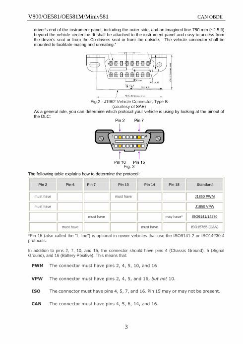
driver's end of the instrument panel, including the outer side, and an imagined line 750 mm (~2.5 ft) beyond the vehicle centerline. It shall be attached to the instrument panel and easy to access from the driver's seat or from the Co-drivers seat or from the outside. The vehicle connector shall be mounted to facilitate mating and unmating."
Fig.2 - J1962 Vehicle Connector, Type B
(courtesy of SAE) As a general rule, you can determine which protocol your vehicle is using by looking at the pinout of the DLC:
Fig. 3
The following table explains how to determine the protocol:
Pin 2 Pin 6 Pin 7 Pin 10 Pin 14 Pin 15 Standard
must have must have J1850 PWM
must have J1850 VPW
must have may have* ISO9141/14230
must have must have ISO15765 (CAN)
*Pin 15 (also called the "L-line") is optional in newer vehicles that use the ISO9141-2 or ISO14230-4 protocols. In addition to pins 2, 7, 10, and 15, the connector should have pins 4 (Chassis Ground), 5 (Signal Ground), and 16 (Battery Positive). This means that:
PWM The connector must have pins 2, 4, 5, 10, and 16
VPW The connector must have pins 2, 4, 5, and 16, but not 10.
ISO The connector must have pins 4, 5, 7, and 16. Pin 15 may or may not be present.
CAN The connector must have pins 4, 5, 6, 14, and 16.
-4-
V800/OE581/OE581M/Miniv581 CAN OBDII
4
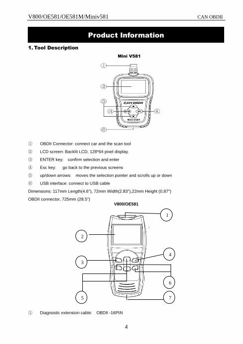
1. Tool Description
Mini V581
① OBDII Connector: connect car and the scan tool
② LCD screen: Backlit LCD, 128*64 pixel display.
③ ENTER key: confirm selection and enter
④ Esc key: go back to the previous screens
⑤ up/down arrows: moves the selection pointer and scrolls up or down
⑥ USB interface: connect to USB cable
Dimensions: 117mm Length(4.6"), 72mm Width(2.83"),22mm Height (0.87")
OBDII connector, 725mm (28.5") V800/OE581
① Diagnostic extension cable: OBDII -16PIN
Product Information
4
6
7 5
1
3
2
V800/OE581/OE581M/Miniv581 CAN OBDII
5
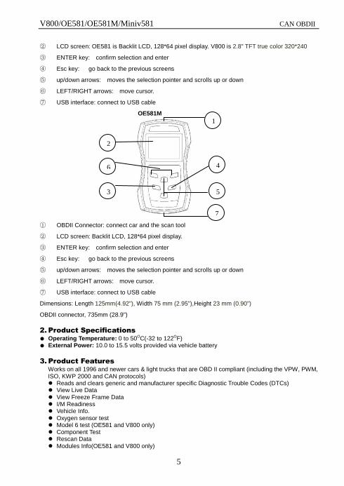
② LCD screen: OE581 is Backlit LCD, 128*64 pixel display. V800 is 2.8" TFT true color 320*240
③ ENTER key: confirm selection and enter
④ Esc key: go back to the previous screens
⑤ up/down arrows: moves the selection pointer and scrolls up or down
⑥ LEFT/RIGHT arrows: move cursor.
⑦ USB interface: connect to USB cable
OE581M
① OBDII Connector: connect car and the scan tool
② LCD screen: Backlit LCD, 128*64 pixel display.
③ ENTER key: confirm selection and enter
④ Esc key: go back to the previous screens
⑤ up/down arrows: moves the selection pointer and scrolls up or down
⑥ LEFT/RIGHT arrows: move cursor.
⑦ USB interface: connect to USB cable
Dimensions: Length 125mm(4.92"), Width 75 mm (2.95"),Height 23 mm (0.90")
OBDII connector, 735mm (28.9")
2. Product Specifications
● Operating Temperature: 0 to 50OC(-32 to 122OF) ● External Power: 10.0 to 15.5 volts provided via vehicle battery
3. Product Features
Works on all 1996 and newer cars & light trucks that are OBD II compliant (including the VPW, PWM, ISO, KWP 2000 and CAN protocols) Reads and clears generic and manufacturer specific Diagnostic Trouble Codes (DTCs) View Live Data View Freeze Frame Data I/M Readiness Vehicle Info. Oxygen sensor test Model 6 test (OE581 and V800 only) Component Test Rescan Data Modules Info(OE581 and V800 only)
1
1
4
1
7
1
6
1
5
1
2
1
3
1
V800/OE581/OE581M/Miniv581 CAN OBDII
6
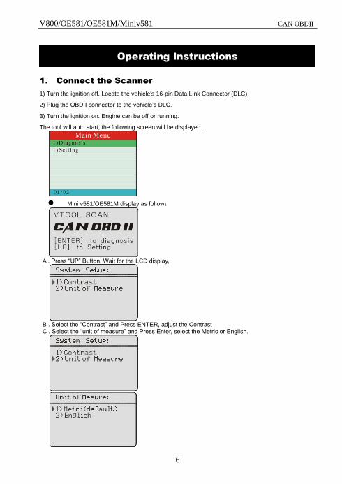
1. Connect the Scanner
1) Turn the ignition off. Locate the vehicle's 16-pin Data Link Connector (DLC)
2) Plug the OBDII connector to the vehicle’s DLC.
3) Turn the ignition on. Engine can be off or running.
The tool will auto start, the following screen will be displayed.
Mini v581/OE581M display as follow:
A . Press ―UP‖ Button, Wait for the LCD display,
B . Select the ―Contrast‖ and Press ENTER, adjust the Contrast C . Select the ―unit of measure‖ and Press Enter, select the Metric or English.
Operating Instructions
V800/OE581/OE581M/Miniv581 CAN OBDII
7
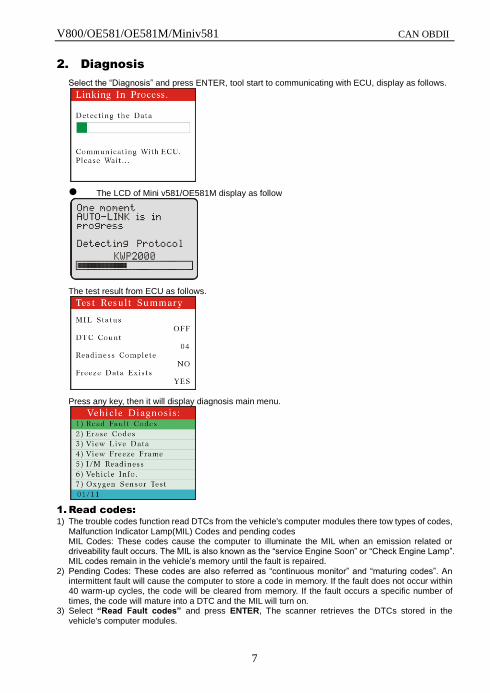
2. Diagnosis
Select the ―Diagnosis‖ and press ENTER, tool start to communicating with ECU, display as follows.
The LCD of Mini v581/OE581M display as follow
The test result from ECU as follows.
Press any key, then it will display diagnosis main menu.
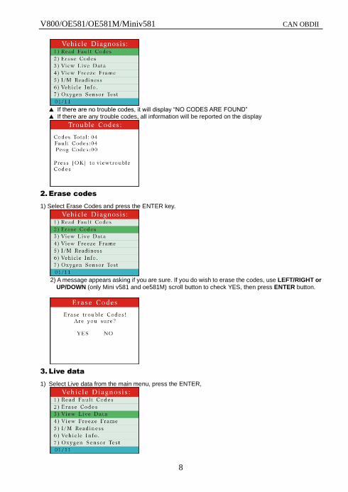
1. Read codes:
1) The trouble codes function read DTCs from the vehicle's computer modules there tow types of codes, Malfunction Indicator Lamp(MIL) Codes and pending codes MIL Codes: These codes cause the computer to illuminate the MIL when an emission related or driveability fault occurs. The MIL is also known as the ―service Engine Soon‖ or ―Check Engine Lamp‖. MIL codes remain in the vehicle’s memory until the fault is repaired.
2) Pending Codes: These codes are also referred as ―continuous monitor‖ and ―maturing codes‖. An intermittent fault will cause the computer to store a code in memory. If the fault does not occur within 40 warm-up cycles, the code will be cleared from memory. If the fault occurs a specific number of times, the code will mature into a DTC and the MIL will turn on.
3) Select “Read Fault codes” and press ENTER, The scanner retrieves the DTCs stored in the vehicle's computer modules.
V800/OE581/OE581M/Miniv581 CAN OBDII
8
▲ If there are no trouble codes, it will display ―NO CODES ARE FOUND‖ ▲ If there are any trouble codes, all information will be reported on the display
2. Erase codes
1) Select Erase Codes and press the ENTER key.
2) A message appears asking if you are sure. If you do wish to erase the codes, use LEFT/RIGHT or
UP/DOWN (only Mini v581 and oe581M) scroll button to check YES, then press ENTER button.
3. Live data
1) Select Live data from the main menu, press the ENTER,
V800/OE581/OE581M/Miniv581 CAN OBDII
9
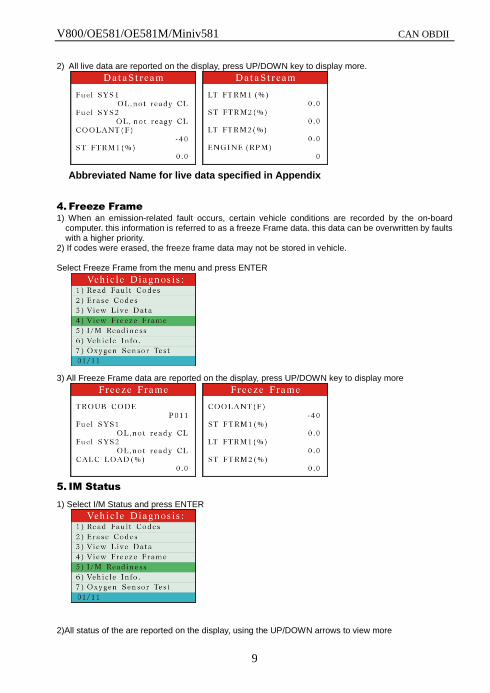
2) All live data are reported on the display, press UP/DOWN key to display more.
Abbreviated Name for live data specified in Appendix
4. Freeze Frame
1) When an emission-related fault occurs, certain vehicle conditions are recorded by the on-board computer. this information is referred to as a freeze Frame data. this data can be overwritten by faults with a higher priority.
2) If codes were erased, the freeze frame data may not be stored in vehicle. Select Freeze Frame from the menu and press ENTER
3) All Freeze Frame data are reported on the display, press UP/DOWN key to display more
5. IM Status
1) Select I/M Status and press ENTER
2)All status of the are reported on the display, using the UP/DOWN arrows to view more
V800/OE581/OE581M/Miniv581 CAN OBDII
10
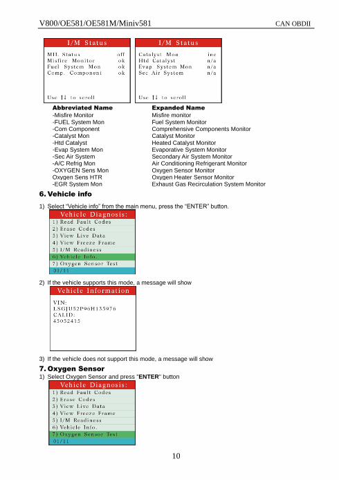
Abbreviated Name Expanded Name
-Misfire Monitor Misfire monitor -FUEL System Mon Fuel System Monitor -Com Component Comprehensive Components Monitor -Catalyst Mon Catalyst Monitor -Htd Catalyst Heated Catalyst Monitor -Evap System Mon Evaporative System Monitor -Sec Air System Secondary Air System Monitor -A/C Refrig Mon Air Conditioning Refrigerant Monitor -OXYGEN Sens Mon Oxygen Sensor Monitor Oxygen Sens HTR Oxygen Heater Sensor Monitor -EGR System Mon Exhaust Gas Recirculation System Monitor
6. Vehicle info
1) Select ―Vehicle info‖ from the main menu, press the ―ENTER‖ button.
2) If the vehicle supports this mode, a message will show
3) If the vehicle does not support this mode, a message will show
7. Oxygen Sensor
1) Select Oxygen Sensor and press "ENTER" button
V800/OE581/OE581M/Miniv581 CAN OBDII
11
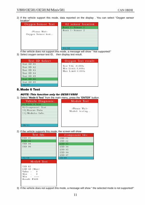
2) If the vehicle support this mode, data reported on the display . You can select ―Oxygen sensor location‖
If the vehicle does not support this mode, a message will show " Not supported!"
3) Select oxygen sensor test ID, then display test result.
8. Mode 6 Test
NOTE: This function only for OE581/V800
1) Select ―Mode 6 Test‖ from the main menu, press the ―ENTER‖ button.
2) If the vehicle supports this mode, the screen will show
3) If the vehicle does not support this mode, a message will show " the selected mode is not supported!"
V800/OE581/OE581M/Miniv581 CAN OBDII
12
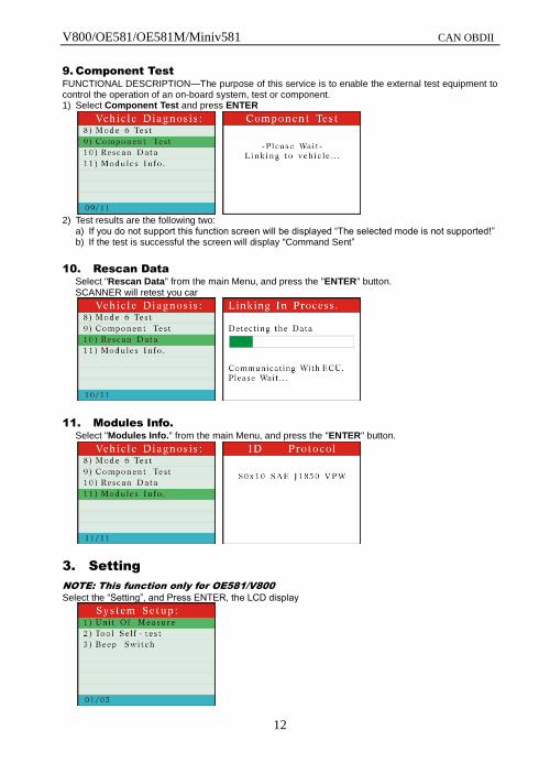
9. Component Test
FUNCTIONAL DESCRIPTION—The purpose of this service is to enable the external test equipment to control the operation of an on-board system, test or component. 1) Select Component Test and press ENTER
2) Test results are the following two:
a) If you do not support this function screen will be displayed ―The selected mode is not supported!‖ b) If the test is successful the screen will display "Command Sent‖
10. Rescan Data
Select "Rescan Data" from the main Menu, and press the "ENTER" button. SCANNER will retest you car
11. Modules Info.
Select "Modules Info." from the main Menu, and press the "ENTER" button.
3. Setting
NOTE: This function only for OE581/V800
Select the ―Setting‖, and Press ENTER, the LCD display
V800/OE581/OE581M/Miniv581 CAN OBDII
13
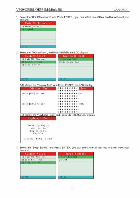
1) Select the ―Unit Of Measure‖, and Press ENTER, t you can select one of their two that will meet your demand.
2) Select the ―Tool Self-test‖, and Press ENTER, the LCD display,
2-1) Select the ―Display Test‖, and Press ENTER, the LCD display,
2-2) Select the ―Keyboard Test‖, and Press ENTER, the LCD display,
3) Select the ―Beep Switch‖, and Press ENTER, you can select one of their two that will meet your demand.
V800/OE581/OE581M/Miniv581 CAN OBDII
14
1. One Year Warranty
1. SCANNER warrants to its customers that this product will be free of all defects in materials and workmanship under normal use and maintenance for a period of one (1) year from the date of the original purchase.
2. This warranty does not apply to damages caused by improper use, accident, abuse, lightning, or if the product was altered or repaired by anyone other than the Manufacturer’s Service Center.
2. Service Procedures
If you have many questions, please contact your local store, distributor or visit our website at www.vehicletooltech,com
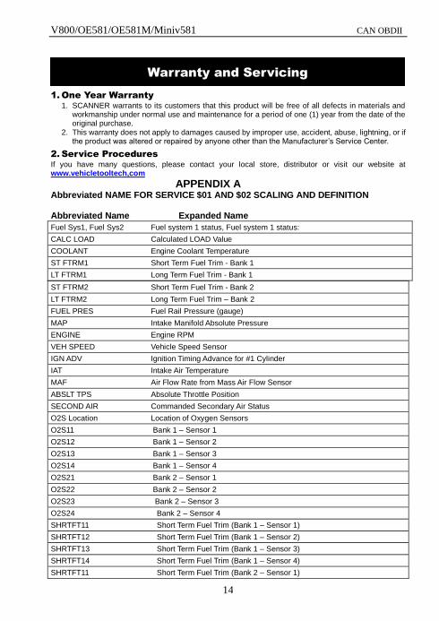
APPENDIX A Abbreviated NAME FOR SERVICE $01 AND $02 SCALING AND DEFINITION Abbreviated Name Expanded Name
Fuel Sys1, Fuel Sys2 Fuel system 1 status, Fuel system 1 status:
CALC LOAD Calculated LOAD Value
COOLANT Engine Coolant Temperature
ST FTRM1 Short Term Fuel Trim - Bank 1
LT FTRM1 Long Term Fuel Trim - Bank 1
ST FTRM2 Short Term Fuel Trim - Bank 2
LT FTRM2 Long Term Fuel Trim – Bank 2
FUEL PRES Fuel Rail Pressure (gauge)
MAP Intake Manifold Absolute Pressure
ENGINE Engine RPM
VEH SPEED Vehicle Speed Sensor
IGN ADV Ignition Timing Advance for #1 Cylinder
IAT Intake Air Temperature
MAF Air Flow Rate from Mass Air Flow Sensor
ABSLT TPS Absolute Throttle Position
SECOND AIR Commanded Secondary Air Status
O2S Location Location of Oxygen Sensors
O2S11 Bank 1 – Sensor 1
O2S12 Bank 1 – Sensor 2
O2S13 Bank 1 – Sensor 3
O2S14 Bank 1 – Sensor 4
O2S21 Bank 2 – Sensor 1
O2S22 Bank 2 – Sensor 2
O2S23 Bank 2 – Sensor 3
O2S24 Bank 2 – Sensor 4
SHRTFT11 Short Term Fuel Trim (Bank 1 – Sensor 1)
SHRTFT12 Short Term Fuel Trim (Bank 1 – Sensor 2)
SHRTFT13 Short Term Fuel Trim (Bank 1 – Sensor 3)
SHRTFT14 Short Term Fuel Trim (Bank 1 – Sensor 4)
SHRTFT11 Short Term Fuel Trim (Bank 2 – Sensor 1)
Warranty and Servicing
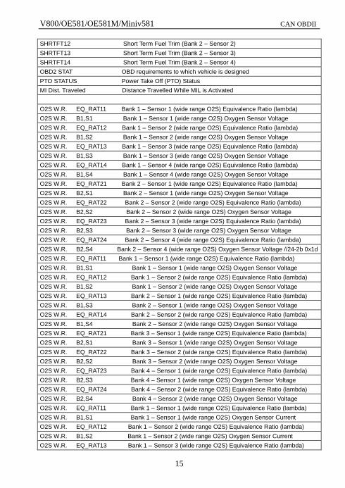
V800/OE581/OE581M/Miniv581 CAN OBDII
15
SHRTFT12 Short Term Fuel Trim (Bank 2 – Sensor 2)
SHRTFT13 Short Term Fuel Trim (Bank 2 – Sensor 3)
SHRTFT14 Short Term Fuel Trim (Bank 2 – Sensor 4)
OBD2 STAT OBD requirements to which vehicle is designed
PTO STATUS Power Take Off (PTO) Status
MI Dist. Traveled Distance Travelled While MIL is Activated
O2S W.R. EQ_RAT11 Bank 1 – Sensor 1 (wide range O2S) Equivalence Ratio (lambda)
O2S W.R. B1,S1 Bank 1 – Sensor 1 (wide range O2S) Oxygen Sensor Voltage
O2S W.R. EQ_RAT12 Bank 1 – Sensor 2 (wide range O2S) Equivalence Ratio (lambda)
O2S W.R. B1,S2 Bank 1 – Sensor 2 (wide range O2S) Oxygen Sensor Voltage
O2S W.R. EQ_RAT13 Bank 1 – Sensor 3 (wide range O2S) Equivalence Ratio (lambda)
O2S W.R. B1,S3 Bank 1 – Sensor 3 (wide range O2S) Oxygen Sensor Voltage
O2S W.R. EQ_RAT14 Bank 1 – Sensor 4 (wide range O2S) Equivalence Ratio (lambda)
O2S W.R. B1,S4 Bank 1 – Sensor 4 (wide range O2S) Oxygen Sensor Voltage
O2S W.R. EQ_RAT21 Bank 2 – Sensor 1 (wide range O2S) Equivalence Ratio (lambda)
O2S W.R. B2,S1 Bank 2 – Sensor 1 (wide range O2S) Oxygen Sensor Voltage
O2S W.R. EQ_RAT22 Bank 2 – Sensor 2 (wide range O2S) Equivalence Ratio (lambda)
O2S W.R. B2,S2 Bank 2 – Sensor 2 (wide range O2S) Oxygen Sensor Voltage
O2S W.R. EQ_RAT23 Bank 2 – Sensor 3 (wide range O2S) Equivalence Ratio (lambda)
O2S W.R. B2,S3 Bank 2 – Sensor 3 (wide range O2S) Oxygen Sensor Voltage
O2S W.R. EQ_RAT24 Bank 2 – Sensor 4 (wide range O2S) Equivalence Ratio (lambda)
O2S W.R. B2,S4 Bank 2 – Sensor 4 (wide range O2S) Oxygen Sensor Voltage //24-2b 0x1d
O2S W.R. EQ_RAT11 Bank 1 – Sensor 1 (wide range O2S) Equivalence Ratio (lambda)
O2S W.R. B1,S1 Bank 1 – Sensor 1 (wide range O2S) Oxygen Sensor Voltage
O2S W.R. EQ_RAT12 Bank 1 – Sensor 2 (wide range O2S) Equivalence Ratio (lambda)
O2S W.R. B1,S2 Bank 1 – Sensor 2 (wide range O2S) Oxygen Sensor Voltage
O2S W.R. EQ_RAT13 Bank 2 – Sensor 1 (wide range O2S) Equivalence Ratio (lambda)
O2S W.R. B1,S3 Bank 2 – Sensor 1 (wide range O2S) Oxygen Sensor Voltage
O2S W.R. EQ_RAT14 Bank 2 – Sensor 2 (wide range O2S) Equivalence Ratio (lambda)
O2S W.R. B1,S4 Bank 2 – Sensor 2 (wide range O2S) Oxygen Sensor Voltage
O2S W.R. EQ_RAT21 Bank 3 – Sensor 1 (wide range O2S) Equivalence Ratio (lambda)
O2S W.R. B2,S1 Bank 3 – Sensor 1 (wide range O2S) Oxygen Sensor Voltage
O2S W.R. EQ_RAT22 Bank 3 – Sensor 2 (wide range O2S) Equivalence Ratio (lambda)
O2S W.R. B2,S2 Bank 3 – Sensor 2 (wide range O2S) Oxygen Sensor Voltage
O2S W.R. EQ_RAT23 Bank 4 – Sensor 1 (wide range O2S) Equivalence Ratio (lambda)
O2S W.R. B2,S3 Bank 4 – Sensor 1 (wide range O2S) Oxygen Sensor Voltage
O2S W.R. EQ_RAT24 Bank 4 – Sensor 2 (wide range O2S) Equivalence Ratio (lambda)
O2S W.R. B2,S4 Bank 4 – Sensor 2 (wide range O2S) Oxygen Sensor Voltage
O2S W.R. EQ_RAT11 Bank 1 – Sensor 1 (wide range O2S) Equivalence Ratio (lambda)
O2S W.R. B1,S1 Bank 1 – Sensor 1 (wide range O2S) Oxygen Sensor Current
O2S W.R. EQ_RAT12 Bank 1 – Sensor 2 (wide range O2S) Equivalence Ratio (lambda)
O2S W.R. B1,S2 Bank 1 – Sensor 2 (wide range O2S) Oxygen Sensor Current
O2S W.R. EQ_RAT13 Bank 1 – Sensor 3 (wide range O2S) Equivalence Ratio (lambda)
V800/OE581/OE581M/Miniv581 CAN OBDII
16
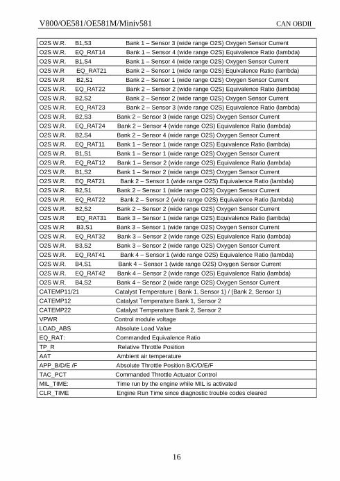
O2S W.R. B1,S3 Bank 1 – Sensor 3 (wide range O2S) Oxygen Sensor Current
O2S W.R. EQ_RAT14 Bank 1 – Sensor 4 (wide range O2S) Equivalence Ratio (lambda)
O2S W.R. B1,S4 Bank 1 – Sensor 4 (wide range O2S) Oxygen Sensor Current
O2S W.R EQ_RAT21 Bank 2 – Sensor 1 (wide range O2S) Equivalence Ratio (lambda)
O2S W.R B2,S1 Bank 2 – Sensor 1 (wide range O2S) Oxygen Sensor Current
O2S W.R. EQ_RAT22 Bank 2 – Sensor 2 (wide range O2S) Equivalence Ratio (lambda)
O2S W.R. B2,S2 Bank 2 – Sensor 2 (wide range O2S) Oxygen Sensor Current
O2S W.R. EQ_RAT23 Bank 2 – Sensor 3 (wide range O2S) Equivalence Ratio (lambda)
O2S W.R. B2,S3 Bank 2 – Sensor 3 (wide range O2S) Oxygen Sensor Current
O2S W.R. EQ_RAT24 Bank 2 – Sensor 4 (wide range O2S) Equivalence Ratio (lambda)
O2S W.R. B2,S4 Bank 2 – Sensor 4 (wide range O2S) Oxygen Sensor Current
O2S W.R. EQ_RAT11 Bank 1 – Sensor 1 (wide range O2S) Equivalence Ratio (lambda)
O2S W.R. B1,S1 Bank 1 – Sensor 1 (wide range O2S) Oxygen Sensor Current
O2S W.R. EQ_RAT12 Bank 1 – Sensor 2 (wide range O2S) Equivalence Ratio (lambda)
O2S W.R. B1,S2 Bank 1 – Sensor 2 (wide range O2S) Oxygen Sensor Current
O2S W.R. EQ_RAT21 Bank 2 – Sensor 1 (wide range O2S) Equivalence Ratio (lambda)
O2S W.R. B2,S1 Bank 2 – Sensor 1 (wide range O2S) Oxygen Sensor Current
O2S W.R. EQ_RAT22 Bank 2 – Sensor 2 (wide range O2S) Equivalence Ratio (lambda)
O2S W.R. B2,S2 Bank 2 – Sensor 2 (wide range O2S) Oxygen Sensor Current
O2S W.R EQ_RAT31 Bank 3 – Sensor 1 (wide range O2S) Equivalence Ratio (lambda)
O2S W.R B3,S1 Bank 3 – Sensor 1 (wide range O2S) Oxygen Sensor Current
O2S W.R. EQ_RAT32 Bank 3 – Sensor 2 (wide range O2S) Equivalence Ratio (lambda)
O2S W.R. B3,S2 Bank 3 – Sensor 2 (wide range O2S) Oxygen Sensor Current
O2S W.R. EQ_RAT41 Bank 4 – Sensor 1 (wide range O2S) Equivalence Ratio (lambda)
O2S W.R. B4,S1 Bank 4 – Sensor 1 (wide range O2S) Oxygen Sensor Current
O2S W.R. EQ_RAT42 Bank 4 – Sensor 2 (wide range O2S) Equivalence Ratio (lambda)
O2S W.R. B4,S2 Bank 4 – Sensor 2 (wide range O2S) Oxygen Sensor Current
CATEMP11/21 Catalyst Temperature ( Bank 1, Sensor 1) / (Bank 2, Sensor 1)
CATEMP12 Catalyst Temperature Bank 1, Sensor 2
CATEMP22 Catalyst Temperature Bank 2, Sensor 2
VPWR Control module voltage
LOAD_ABS Absolute Load Value
EQ_RAT: Commanded Equivalence Ratio
TP_R Relative Throttle Position
AAT Ambient air temperature
APP_B/D/E /F Absolute Throttle Position B/C/D/E/F
TAC_PCT Commanded Throttle Actuator Control
MIL_TIME: Time run by the engine while MIL is activated
CLR_TIME Engine Run Time since diagnostic trouble codes cleared


![] .vPW - Melbourne Law School](https://img.pdfslide.us/doc/110x75/6159d5ffc6b5be182f44f796/-vpw-melbourne-law-school.jpg)