Embed Size (px)
Citation preview
VERICUT 7.4.2 Interim Release (VERICUT)
Release Notes
March 14, 2016 VERICUT Version 7.4.2 is available for all supported Windows platforms.
V 7.4.2 contains everything described below for V7.4 and V7.4.1, plus the following additional fixes/enhancements.
CAM Interfaces The CATIA V5-to-VERICUT Interface (CATV5) is enhanced to look for part names first, and then part numbers when automatically filling certain fields in the CATV5 interface.
The CATIA V6-to-VERICUT Interface (CATV6) now passes CATV6 models correctly scaled when CATIA Units are set Inches.
The Edgecam-to-VERICUT Interface (ECV) now transfers fixture models from the Edgecam 2015R1 Workflow User Interface.
The Edgecam-to-VERICUT Interface (ECV) is enhanced so that probe tools created in Edgecam are passed to VERICUT as Probe tools.
The Edgecam-to-VERICUT Interface (ECV) is enhanced to support European Diameter symbols (ø or Ø) in tool descriptions.
The Edgecam-to-VERICUT Interface (ECV) is enhanced so that if environment variable CGTECH_SINGLE_PLATFORM is set to Yes, then vericut.bat gets the "LIMITED" argument string added.
Unexpected Edgecam-to-VERICUT Interface (ECV) termination no longer occurs when using a specific VERICUT template that references a machine that does not have an associated machine file.
The GibbsCAM-to-VERICUT Interface (GibbsV) now correctly positions the Stock model from a specific GibbsCAM part file when it is passed to VERICUT. This fix is implemented in GibbsV 7.4 for GibbsCAM 2015 v11.
Pre-V7.4 GibbCAM-to-VERICUT Interface (GibbsV) subsystem data is now correctly read into the V7.4 GibbsCAM-to-VERICUT Interface.
In GibbsCAM-to-VERICUT Interface (GibbsV), the Make New Folder button is now correctly displayed in the Select Output Directory, Browse for Folder window.
The GibbsCAM-to-VERICUT Interface (GibbsV) now correctly passes a specific GibbsCam tool to VERICUT.
The GibbsCAM-to-VERICUT Interface (GibbsV) now correctly accounts for the length of the tool that sticks out of the holder when passing tools to VERICUT.
The GibbsCAM-to-VERICUT Interface (GibbsV) now passes VERICUT a specific drill tool in the correct orientation.
The GibbsCAM-to-VERICUT Interface (GibbsV) now passes VERICUT the correct tool insert for as a specific insert profile containing duplicate points and overlapping line segments.
The GibbsCAM-to-VERICUT Interface (GibbsV) now correctly passes “Do not Spin with Spindle” settings with Holders passed to VERICUT.
The GibbsCAM-to-VERICUT Interface (GibbsV) now correctly passes “Do not Spin with Spindle” settings for simple tools passed to VERICUT.
A specific Mastercam tool no longer changes shape when passed through the Mastercam-to-VERICUT Interface (MCAMV) to VERICUT.
The Mastercam-to-VERICUT Interface (MCAMV) now correctly passes the Mastercam "Shoulder Diameter" value to VERICUT as the “Shank Diameter” value.
The Mastercam-to-VERICUT Interface (MCAMV) now correctly passes the Mastercam "Neck Diameter" value to VERICUT.
The Mastercam-to-VERICUT Interface (MCAMV) is enhanced to support reamer tools.
The NX-to-VERICUT Interface (NXV) now correctly retains the “Use Selected Tool Library” setting.
The NX-to-VERICUT Interface (NXV) now correctly orients the tools, from a specific project file, when passing tools to VERICUT.
The NX-to-VERICUT Interface (NXV) now correctly passes a groove cutter, in a specific project file, to VERICUT.
The PowerMill –to VERICUT Interface now passes the correct SOR Tool profiles to VERICUT when they contain duplicate points.
In the Pro/E-to-VERICUT Interface (PROEV), a message is now output after clicking on the PROEV Generate and Run button when the version of VERICUT that PROEV needs to start does not exist. This is implemented in PROEV 7.4 for Creo 3.0.
The Pro/E-to-VERICUT Interface (PROEV) now enables you to export all coordinate systems created in Pro/E for a specific operation.
The Pro/E-to-VERICUT Interface (PROEV) is enhanced so that for all parametric milling tools, PROEV will check to see if a tool "attachment" is defined in the NC sequence for that tool and if defined, it will use the defined "attachment" as the tool's holder.
The Pro/E-to-VERICUT Interface (PROEV) is enhanced to create SOR Holder models from Holder profiles created in Pro/E.
The Pro/E-to-VERCUT Interface (PROEV) for Creo 3.0 now locates the models from a specific Pro/Engineer manufacturing assembly correctly when passed to VERICUT.
The Pro/E-to-VERCUT Interface (PROEV) now supports parametric cutters with Holder Models.
G-Code Processing A new Override Text Value, "RETURN= your_pogo_var_name" is added to the Pogo macro enabling the distance between the pogo_cup and the stock to be saved in the variable "your_pogo_var_name".
New macro, SetRotationPlaneZVectorVars, is added to provide access to components of the Z axis vector from the Rotation Plane matrix.
A “StringIndexOutOfBoundsException: String index out of range: -7” error is no longer output to the Logger when the G-Code Processing window is opened with a specific project file is loaded.
Cutter Compensation is no longer cancelled when in Rapid mode for a specific project file that has the CutterCompFull macro in Events is set with Override Value = 1.
Macro FlyAwaySetClampOnOffZone is updated to support zones being specified in machine coordinates. To use machine coordinates, call the FlyAwayCoordinateSystem macro with an Override Value = 1 during start of processing.
Notes: 1. Using machine coordinates will not work with RTCP and 5 axis motion while
in fly away mode. 2. Using Machine coordinates will not work with Cutter Compensation while in
fly away mode.
Macro FlyAwaySetClampOnOffZone now works correctly when the C-axis head is not at zero.
Unexpected VERICUT termination no longer occurs when processing an M30 command in a specific project file.
Variable assignment is enhanced to more accurately represent machine controls.
Support is added for the Heidenhain continuation character ~ (tilde).
Stop At Text is now supported within a control subroutine by toggling on the Debug Control Subs feature on the Settings window, G-Code Outputs tab.
Support is added for the Siemens Sin840D absolute path feature.
New macro, MountToolID, is added to support mounting tools with alphanumeric tool IDs.
Support is added for the Heidenhain iTNC 530: Add Syswrite ID 503 command.
The SiemensTRWorkCoord macro, used in a specific project file, now produces the correct offsets.
A new Override Text value, set_nc_macro_local_vars, is added to the GLType2CLS macro to enable setting local variables when the macro is called.
The SiemensTRWorkCoordinate macro now works correctly when used in a specific project file.
The Heidenhain command Plane RELATIV now works correctly in VERICUT Heidenhain controls.
The Okuma OSP300 G83 command is now supported using I & J values.
The SiemensTRWorkCoordinate macro now works correctly when used in a specific project file using a multi-channel machine.
Support is added for the Heidenhain SYSWRITE 503 command.
Probe commands are enhanced to support the Siemens ACP and ACN commands.
Two new macros, EIARotaryLocalDisplay and EIARotaryMachineDisplay, are added to support how rotary values are represented in the Status window, the SubSystem Motion window, and within Dynamic variables.
A Cycle800 command followed by a SUPA command no longer causes a shift in the driven point zero location.
New macro, RotationPlaneScale2, is added to enable applying a scaling factor, as specified by the RotationPlaneXScale, RotationPlaneYScale, and RotatonPlaneZScale macros, to the existing rotation plane while ignoring any existing scaling factors.
A "StringIndexOutOfBoundsException: String index out of range: -7" error no longer displays in the Logger when trying to open the G-Code Processing window.
Cutter Compensation is no longer cancelled in Rapid mode.
VERICUT now correctly processes the radial clearance on last cut of a rough turn cycle in a specific project file.
The M98P[#999+2] block, in a specific project file, is now processed correctly.
The looping behavior in a specific project file, that has two subprograms, now produces the correct behavior.
A G66 command now works correctly.
The Heidenhain SYSWRITE 502 command now works correctly in a specific project file.
Machine Simulation A collision is no longer missed when processing a specific project file.
The Stop button now works correctly for a specific project file using a multi-channel machine.
Importing an inch machine or complete Project into a metric session now correctly updates the Tool Change Retraction Table.
A reviewer file created from a specific mill turn project file with a part transfer from the main spindle to the sub spindle now plays correctly in the Reviewer.
Reviewer A “Tools” icon is now available in Reviewer Tool Bar enabling you to access the Tools window.
A specific Reviewer file save in V7.4.1 now opens correctly in the Reviewer.
Unexpected Reviewer termination no longer occurs when playing a specific Reviewer file.
Reviewer has been enhanced to include control and machine subroutines in the Reviewer file enabling a Reviewer file created from a specific project file to be played correctly in the Reviewer.
A reviewer file created from a specific mill turn project file with a part transfer to from the main spindle to the sub spindle now plays correctly in the Reviewer.
Tool Manager NX tools are now imported correctly to VERICUT using the Import CAD Tool feature in Tool Manager.
Color and orientation are now correct in V7.4.2 for probe tool components referenced in a V7.3 tool library.
A specific V7.0 tool library file, created in TDM, now opens revolved profile tools correctly in V7.4.2.
A specific project file, using a revolved profile tool created in V7.2.3, no longer hangs up the session on the tool change loading the tool.
Revolved profile tools created prior to V7.4.1 now open correctly in V7.4.2.
Holders that are referencing step files imported from TDM are now created properly during VERICUT processing.
STEP files used for tool holders, in a specific project file, no longer disappear when the Tool Manager window is open and a Reset is done.
STEP files used for tool holders, in a specific project file, now display correctly.
SOR Tool profiles with duplicate points will now create the 3D cutter.
Adding points to define a tool profile in Tool Manager no longer removes points as you add new ones.
Changing the color of a thread insert now works correctly.
The Tool Manager Automatic Stack function now works correctly when adding cutter components to a specific tool library file.
A specific inserted step drill now removes material correctly.
A Taper Ball Nose End Mill defined as a Revolved Cutter in the Tool-Manager now only applies the entered B-Angle to the current tool.
The right-click menu on the Tool Information tab in Tool Manager now correctly writes to the clipboard so that you can Cut/Copy and Paste the selected information.
When a new cutter component is added, it now correctly receives "focus" for additional actions.
3D tools that worked correctly in a pre-V7.4 version now work correctly in V7.4.2.
Unexpected Tool Manager termination no longer occurs while defining profiles with the Model File Edge Display feature turned on.
CAD Tool Import now works correctly with a specific set of tools imported from TDM.
Tool Manager now correctly creates a tool list when using a quotation mark to describe Inch as units.
The Search Tool window, Duplicate feature now works correctly when the Tool List in Tool Manager does not contain any tools.
A specific tool with very small radii (.003) is now correctly imported to tool Manager in a DXF file.
The Revolve Profile or Sweep Profile features in Tool Manager have been enhanced in the following ways:
• The Close Profile button now behaves as its name suggests. The profile only gets closed when you press the Close Profile button.
• Valid profiles are displayed in blue. If any modification in the profile data causes it to become an invalid tool profile, the tool profile will become displayed in red. The tool profile display will return to being displayed in blue as soon as the tool profile is corrected to become a valid tool profile.
• Separate Undo features for profile sketcher have been removed and are now accomplished using the Undo feature in the Tool Manager window, Tool Bar.
• You are able to save an invalid tool profile to the tool library file but any tool with an invalid cutter insert or holder profile will not be displayed in the Tool Manager graphic window and will not be used in the simulation.
• Edits to Revolve Profile or Sweep Profile tools are now applied dynamically.
Tap tools in an external tool library can now be referenced for use in a Hole Making tool assembly.
Unexpected VERICUT termination no longer occurs when a specific tool library file, saved in Turbo Soft, and containing duplicate Tool IDs is opened in VERICUT.
A Qualified Dimension is no longer added to a specific Milling tool created from a STEP model file.
A specific CAD Milling tool no longer automatically adds a Qualified Dimension when a Driven point is added.
A specific tool now displays correctly in Tool Manager.
Unexpected Tool Manager termination no longer occurs when creating a new tool library file and clicking on Driven Point ID or Value in the Tool Manager Information tab.
A “Radius, single end” turning insert can now be successfully created and modified.
In the Import CAD Tool window, the Remove reference to CAD File in the saved tool feature now correctly creates the Holders in a Probe Tool assembly as VERICUT Polygon files.
Referenced tapping tools from a V7.3 tool library now displays the correct Reference window needed to create/modify a referenced tap tool.
3D tools that use revolved cutters in combination with inserts are now supported.
When importing tools via the Zoller interface, the gage point is now correctly set.
A specific tool now imports correctly using the NOVO interface. The following error messages are now output when a STEP file is not specified in the XML file for a tool or when a specified STEP file does not exist in the "Models" directory:
1. "A STEP file is specified in the XML file, but does not exist in the "Models" directory."
2. "A STEP file is NOT specified in the XML file for a tool."
A specific DXF tool profile is now correctly imported to VERICUT using the DXF Geometry window.
A specific referenced holder assembly now gets oriented correctly for tap tools.
A specific tool assembly imported from TDM now correctly imports the tool inserts.
Chamfers and fillets can now be created using the Tool Manager Profile Sketcher.
The Tool ID no longer gets changed to the component name after a new component is renamed.
Unexpected VERICUT termination no longer occurs when trying to access TDM.
The pitch for an existing tap tool can now be modified.
False "D value must be greater than R - Corner Radius" errors are no longer output when defining a "Round, single end" insert.
Verification False variable errors are no longer output for a specific project file using a Toshiba control.
The radius compensation, when using a specific STEP turning insert, is now correct.
The Siemens 840D - TRANS statement now works correctly in a specific project file.
Tools are no longer output twice in VERICUT reports when using In-Process files.
An incorrect simulation, on a specific client computer, caused by an uninitialized variable in Siemens_P_PFRAME_FI is fixed.
Local variables are no longer deleted when an M99 command is used in a specific project file.
Material removal is now correct for a specific project file when the tool is oriented in position other than 0 or 90 degrees.
Angle values can now be entered for a model after the component that it is associated with has been rotated.
VERICUT no longer outputs the error message, "Error: Tool spindle spinning in wrong direction for tool "1" loaded in component "Tool" ", for a specific inserted tool regardless of the specified spindle direction.
A specific inserted step drill now removes material correctly.
A Tool List in a specific pre-V7.4 project file now successfully builds the Tool List.
VERICUT no longer loses all the panels that were docked to the Project Tree when you use the toolman.bat file.
New feature, “Display confirmation before resetting simulation”, is added to the Preferences window: Start-up tab enabling you to redisplay the “Reset the simulation?” Prompt after you have previously selected “Do not display this notice again” feature.
The VERICUT version is now displayed in the VERICUT Log File header.
Using the Collision and Travel Limit window: Collision Detect tab to turn off a machine collision record, after the simulation has started, now correctly turns off collision detection for that record.
A new feature, Sketches to keep, is added to the Cutcom Sketch window enabling you to suppress the creation of Cutcom sketches.
A specific project file no longer adds material during the simulation when the Animation Speed Slider is set between 1% and 2%.
Material removal with a specific round insert, where the insert profile consists of one full circle, is now correct.
A specific radius cutter created from a revolved profile in Tool Manager, now accurately transfers the cutter's shape to the stock.
Interpolation with CP IPA (CP IPA+390 DR+) in a specific project file now produces the correct results.
Material removal using a specific Thread Mill Profile Tool is now correct.
The Change Tool by List feature is enhanced to support comments within the Tool ID. For example, "102" and "102 TT 80deg Sub Vet" is now considered a match.
A false holder collision is no longer reported while cutting a complex inside turning workpiece in a specific project file.
Unexpected VERICUT termination no longer occurs when deleting the Driven Point ID for a specific tool.
Collisions are now correctly reported for rapid positioning motion events between the tool tip and the stock on approach moves between cuts in Z while simulating a G72 rough turning cycle in a specific project file.
Phantom extra material is no longer added to the spinning stock, resulting in collisions with tools and the turret, in a specific project file.
A VERICUT solid, saved with features, now correctly displays the turned radii in a Profile view.
Unexpected VERICUT termination no longer occurs on the line following the processing of a subroutine in a specific project file.
A thread milling operation in a specific project file now produces the correct thread.
The cause of a significant performance regression in a specific project file is fixed.
A false Holder/Stock collision is no longer reported when simulating a specific turning project file.
Simulating a specific project file, that uses RPCP on certain 5-axis motions, no longer produces gouges or rough and wavy surfaces.
Simulating a specific project file now correctly outputs the following error, "Error: The resulting actual Feedrate (units per minute) for the current motion is 0.0" when the spindle is turned off and feed mode is set to FeedModeRevolution.
In the Color window: Cut Colors tab, the correct color table now displays when you set Color Method to Feed Range Color.
A Z motion with CutterCompFull macro with Override Value set to 1, in a specific project file, no longer caused the tool to crash into the part.
A specific project file now processes correctly when the CutterCompFull macro with Override Value set to 1.
The graphics display is now correct for a specific project file that is making a very shallow (about 0.005 deep) 5-axis cut around a hemisphere.
Unexpected VERICUT termination no longer occurs when simulating a specific multi-channel project file.
Unexpected VERICUT termination no longer occurs when simulating a specific project file using a Fanuc G66.1 command.
VERICUT Drill and Fastener Simulation (VDAF) The IJK2ABCType macro with Override Value = 32 is updated to support a Brown model 1407 MDDS Auto Drill and Fastening machine.
Miscellaneous When a model used to open a .STP file has been copied and pasted, and the pasted model has the Remove Reference feature toggled on, the reference is now correctly removed and the model is correctly converted to a VERICUT Polygon (.ply) format.
Unexpected lsclean.exe termination no longer occurs when executing the Sentinel command lsclean timefix.lf.
License Server is a now a separate installation so when you only install the license server you still get the License Administration, License Server Only and Utilities menu options.
Support is added for the character ° in the CGTech Post-Processor.
A problem in the License Generator that was causing a false error message: "Unable to execute program due to invalid CGTech License Company information" is fixed.
The VERICUT installer is revised to always install and use a separate Java JRE
AUTODIFF is enhanced in the following ways:
• the NC Program jumps to the position where the selected error in AUTO-DIFF report occurred.
• will jump into project subroutines if that is where the error in the AUTODIFF Report occurred
• the appropriate tool will be selected if multiple NC programs have been used
NC Program Review no longer displays the wrong tool path, in a specific project file, when Set Start is set at the first line in the NC program.
STEP files are now loaded correctly in VERICUT and in the Tool Manager: Import CAD Tool window after dragging a .vcproject file and dropping it on a VERICUT icon to open VERICUT with the selected project file.
Copying an existing center drill component and pasting it to a new Hole Making tool no longer loses the center drill definition in the new tool assembly.
When suppressing circular output and just outputting points (GOTO's), the Interpolation Tolerance value enables you to increase the number of points when converting a circle into a series of points.
OptiPath now creates the correct optimized NC program file for a specific project file that uses a facing head.
The VERICUT installer now sets the correct path to the CATIA V5-to-VERICUT Interface (CATV5) in CATV.CATScript.
The library sin840d control is enhanced to support the Siemens Cycle61 milling cycle command.
New Macros in V7.4.2
The following new macros are added for V7.4.2:
ActivateAxes
AutosetArrayVars
AutosetToolManOnOff
CycleTurnGrooveAllowance
CycleTurnGrooveAngleEnd
CycleTurnGrooveAngleStart
CycleTurnGrooveChamfer
CycleTurnGrooveEndX
CycleTurnGrooveEndY
CycleTurnGrooveEndZ
CycleTurnGrooveFaceFinish
CycleTurnGrooveRadiusBottom
CycleTurnGrooveRadiusTop
CycleTurnGrooveStartX
CycleTurnGrooveStartY
CycleTurnGrooveStartZ
CycleTurnGrooveToolWidth
DynamicToolTipAutoAdjustAngle
EIARotaryLocalDisplay
EIARotaryLocalMachineDisplay
FlyAwayCoordinateSystem
InActivateAxes
RotationPlaneScale2
SetDfmtPrecision
SetProjectInfoVars
SetProgramZeroCsys
SetRotationPlaneZVectorVars
SiemensORISOL
SiemensORISOLAxisOrder
TapeCacheRollerOff
TapeCacheRollerOn
WTapeMTProcessingOnOff
WTapeMTTapeMotionReset
WTapeMTTapeOffset
WTapeMTTowNumber
ZeroAxisDisplayDrivenAxes
VERICUT 7.4.1 Interim Release Notes Release Notes October 8, 2015 VERICUT Version 7.4.1 is available for all supported Windows platforms. V 7.4.1 contains everything described below for VERICUT 7.4, plus the following additional fixes/enhancements. CAM Interfaces A new environment variable, CGTECH_CATV_SKIP_OPTIPATH is added to enable not having OptiPath records appended tools created in CATIA V5 when they are passed through the CATIA V5-to-VERICUT Interface (CATV) to VERICUT. Add set CGTECH_CATV_SKIP_OPTIPATH=Yes to the batch file used to start CATV. By default OptiPath records are added to the tools.
The Mastercam-to-VERICUT Interface (MCAMV) now passes a Holder profile in a specific project file correctly.
The GibbsCAM-to-VERICUT Interface (GibbsV) now correctly displays the first character in the GibbsV VERICUT Interface window and on all of its tabs when the used in a Japanese environment (Japanese characters).
G-Code Processing The motion plane no longer changes when cutting a circular motion in a specific project file that defines the circle plane using G2/G3 codes and cutter compensation active.
When processing Siemens ACP and ACN commands, VERICUT now recognizes a 360 degree position on a circle and a 0 degree position on a circle as the same location and no longer causes a full 360 degree motion around the circle.
The CylindricalInterpolation macro is enhanced to support virtual X and Y axes. By default, the CylindricalInterpolation macro turns the virtual axis off, and processes the command using the real X axis. Setting the Override Text value to VIRTUAL causes the macro to process the command using the virtual axis.
Reviewer A problem preventing pre-V7.4 Reviewer files to be read in V7.4 is fixed. Pre- V7.4 Reviewer files are now able to be read in V7.4.1. Reviewer files created in V7.4 will only be able to be read in V7.4.
The Reviewer now displays a splash screen when it starts up.
Tool Manager VERICUT now produces the correct revolved cutter profile from a specific STEP file containing a sphere.
The width of the Tool List and Coordinate Systems panel on the left side of the Tool Manager window is no longer limited by the length of the longest Tool ID. The width of this panel can now be made wider, or narrower, than the length of the longest Tool ID.
Verification A problem preventing pre-V7.4 In Process files to be read in V7.4 is fixed. Pre- V7.4 In Process files are now able to be read in V7.4.1. In Process files created in V7.4 will only be able to be read in V7.4.
Unexpected VERICUT termination no longer occurs when trying to Merge an In Process file.
Double clicking on an In Process file in the Project Tree now opens the In Process file instead of doing a Merge In Process file.
A false cutter compensation error is no longer generated when processing a specific project file that has the G-code setting set to "On - Default to Full Radius".
The X-Caliper values obtained in a Profile view are now relative to the origin of the active coordinate system consistent with all other VERICUT view types.
The toolpath in a specific project file is now correct when the CutterCompFull macro is called with Override Value = 1.
The CutterCompFull macro now appropriately reports a "Compensation value too large for Small Contour Steps: M97 required" message when called with Override Value = 1.
Holder/Stock and Holder/Fixture collisions are now correctly reported for a Water Jet tool when the jet is turned off.
The X-Caliper: Thickness feature now returns the correct thickness value for a turning Stock, in a Workpiece view, when the Stock has started spinning but no turning cuts have been done yet.
The Esc key can now be used to pause a VERICUT simulation like it did in pre-V7.4 versions of VERICUT.
Unexpected VERICUT termination no longer occurs when processing a specific project file.
Syntax Check no longer outputs a false syntax error when checking for characters before/after a mathematical operation in a specific project file.
VERICUT now releases the NC program after closing the NC Program window and doing a Reset so that the current NC program can be over-written after be edited using an external editor and re-posted.
Miscellaneous All Type entries in the File Summary window are now translated when VERICUT is run with a Portuguese VcRes.local file.
The motion is now correct when processing a specific Siemens 840d Cycle800 command in a specific project file.
A false "Unable to execute program due to invalid CGTech License Company information" is no longer output when the time zone where the license server computer is located is earlier than the time zone where the computer running VERICUT is located. For example, if the license server was in New York and the customer runs VERICUT in Chicago or Los Angeles.
New Macros in V7.4.1
CycleTurnAllowanceY
CycleTurnContourBlankSub
CycleTurnContourReverse
CycleTurnContourSub
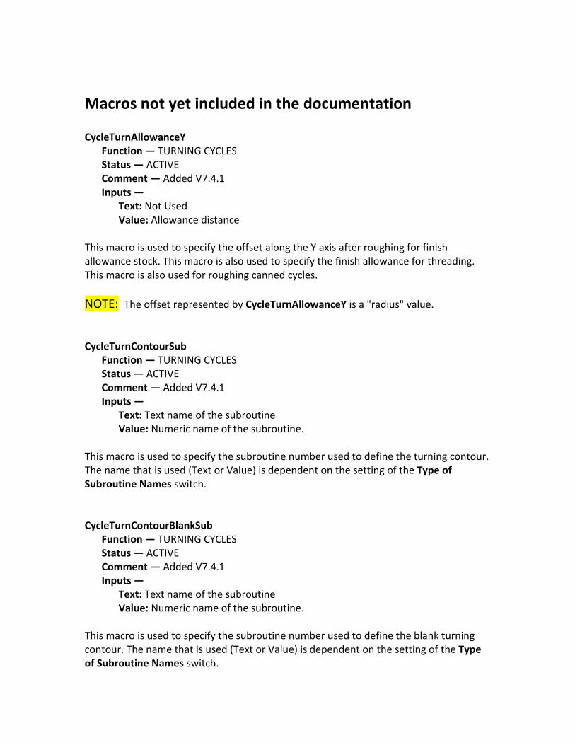
Macros not yet included in the documentation CycleTurnAllowanceY
Function — TURNING CYCLES Status — ACTIVE Comment — Added V7.4.1 Inputs —
Text: Not Used Value: Allowance distance
This macro is used to specify the offset along the Y axis after roughing for finish allowance stock. This macro is also used to specify the finish allowance for threading. This macro is also used for roughing canned cycles. NOTE: The offset represented by CycleTurnAllowanceY is a "radius" value. CycleTurnContourSub
Function — TURNING CYCLES Status — ACTIVE Comment — Added V7.4.1 Inputs —
Text: Text name of the subroutine Value: Numeric name of the subroutine.
This macro is used to specify the subroutine number used to define the turning contour. The name that is used (Text or Value) is dependent on the setting of the Type of Subroutine Names switch. CycleTurnContourBlankSub
Function — TURNING CYCLES Status — ACTIVE Comment — Added V7.4.1 Inputs —
Text: Text name of the subroutine Value: Numeric name of the subroutine.
This macro is used to specify the subroutine number used to define the blank turning contour. The name that is used (Text or Value) is dependent on the setting of the Type of Subroutine Names switch.
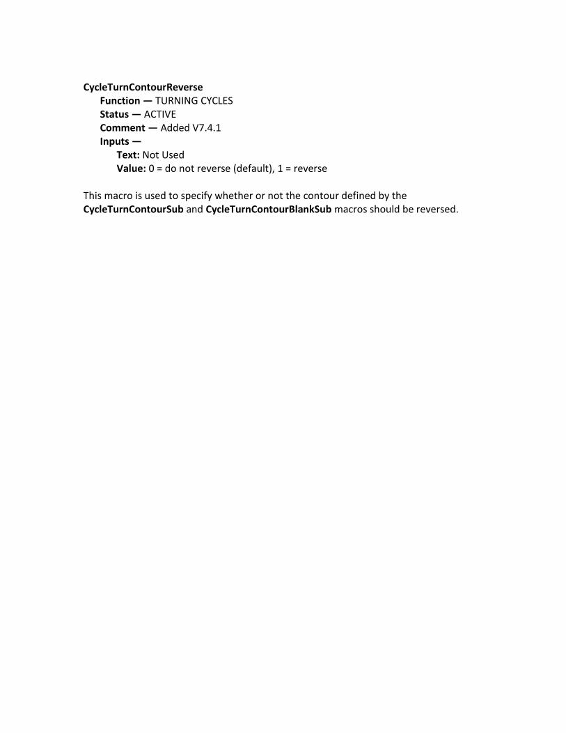
CycleTurnContourReverse
Function — TURNING CYCLES Status — ACTIVE Comment — Added V7.4.1 Inputs —
Text: Not Used Value: 0 = do not reverse (default), 1 = reverse
This macro is used to specify whether or not the contour defined by the CycleTurnContourSub and CycleTurnContourBlankSub macros should be reversed.
What's NEW in VERICUT 7.4
IMPORTANT! - Licensing is NOT included in software shipments. See "How to get a license" below for details.
August 18, 2015
Dear VERICUT® User:
Thank you for your continued investment in VERICUT, an important part of your NC programming and machining process!
The VERICUT 7.4’s NC program simulation, verification, and optimization technology is packed with new features making it more powerful and easier to use. This letter describes important changes in VERICUT 7.4. Take a moment to review what's new and improved in this release.
Maintenance and Licensing Information
Software maintenance keeps you on the cutting edge - CGTech provides update software to customers with current software maintenance. Your continued maintenance ensures that you have the most advanced verification technology available. If your maintenance has expired, please contact your CGTech representative (http://www.cgtech.com/about/contact-us/).
Sincerely,
Bill Hasenjaeger
CGTech Product Marketing
How To Get a License - All users must complete and return the License Request Form in the CD booklet, or submit the application at http://www.cgtech.com/vericut_support/request-license/. Licensing is sent via Email only.
NOTE: This software requires a VERICUT 7.4 license.
VERICUT 7.4 Release Notes August 18, 2015
VERICUT VERSION 7.4 is not available for 32 bit Windows computers. It will only run on 64 bit Windows, and is only officially supported on Windows 7 computers.
VERICUT’s license server will continue to run and be supported on 32 bit or 64 bit computers.
Both VERICUT and the license server can be installed by both 32 bit and 64 bit computers. When installing VERICUT with a 32 bit computer you will be warned that it can only run on 64 bit systems. The warning will not display when installing the license server.
V7.4 Enhancements Ease of Use Enhancements Welcome Screen
A Welcome Screen automatically displays when you first start a VERICUT session. The features on the Welcome Screen provide access to commonly used first actions for a VERICUT session.
These features include starting a new project file, opening an existing project file, providing access to recently opened project files and access to saved template files.
The Welcome Screen also provides access to VERICUT Training videos and VERICUT Training sessions if they have been installed in your VERICUT installation.
New Docking Method
VERICUT’s desktop is enhanced with a new docking method enabling you to lay out your VERICUT desktop in the most efficient manner for the way that you work. The new docking method is very flexible and provides a high level of customization possibilities.
VERICUT dockable panels have three possible docking states, as an Overlay panel, as a Docked panel or as a Floating panel. A few of the panels have limited choices because of how they are used by VERICUT. Any dockable panel can be configured with multiple tabs. Tabbed panels can be displayed in the same three states as any other dockable panel.
Status Window
The Status window is completely redesigned for better viewing, customization and size. The new Status window is completely configurable. The Status window information is divided into Information Groups, each containing a specific list of information. You have the ability to choose which Information Groups that you want displayed and which items of information that you want displayed in each of the Information Groups.
You also have the ability to display the Information Groups in any order that you choose. You can also display your Status window in either a vertical or horizontal orientation.
You can now display the Status window for multiple sub-systems at the same time.
Consolidated Windows
The contents of a previous collection of windows (Properties, Output Files, G-Code Outputs, G-Code Settings, APT Settings and Auto Save) have been consolidated into a single, tabbed window in one easy to find location.
View Port Controls (View Cube)
View orientation is now much easier to manipulate directly from VERICUT’s desktop. The VERICUT View Port controls, or View Cube, tracks the rotation of the view that is currently active in the VERICUT Graphics area. Pan and Zoom have no effect on the cube. When you rotate the view in the graphics area, the cube rotates to the same orientation. Conversely, if you rotate the cube in the View Port control area, view in the graphics area will rotate to the same orientation.
The entire cube is a combination 26 buttons that are triggered by a left click. 12 edge views represented by the cylinders on the edges of the cube, 8 isometric views represented by 8 spheres at the corners of the cube and 6 standard views represented by the labeled sides of the cube.
View layouts are saved with all views currently displayed on your desktop. View layouts are stored and selected graphically.
Tool Manager
Tool Manager’s desktop and user interface is re-designed to enable easier user interaction. The following is a summary of the Tool Manager enhancements:
• A new Tool Bar located at the top of the Tool Manager window consists of a combination of icons and pull-down menus providing easy access to all features needed to create and maintain tool libraries, create/modify tool assemblies, import tool assemblies and create or import OptiPath records.
• In the Tool List, tool components now have a Parent/Child hierarchy allowing for better tool assembly management and modification.
When a new tool is added to the Tool List, the tool is created with a holder component and a cutter component arranged in the new Parent/Child hierarchy.
Tools in the Tool List now display the tools description when one has been specified.
• The center of the Tool Manager window now consists of two tabs.
The Tool Information tab is automatically displayed when a tool record in the Tool List Area is highlighted or whenever a new tool assembly is added enabling you to specify/modify tool related information (Description, Gage Point, Driven Point(s), Cutter Compensation records, etc.).
The Tool Force Data tab has features that enable you to specify Cutter and Feed Optimization characteristics for tools to be used by the VERICUT Force NC program optimization tool.
When Tool Definition windows are needed, they now replace the center section of the Tool Manager window instead of displaying on top of the Tool Manager window like in previous releases. The appropriate Tool definition window is automatically displayed when a Cutter or Holder component is highlighted in the Tool List.
All Tool Definition windows have been re-designed to make tool definition easier. New icons make each tool type clearer. New tool images and method for defining tools make the tool definition process easier.
A new Hole Making tool type (Drills, Reamers, Center Drills and Taps) better aligns with current CAM systems and tools in the workshop.
When the Configure Coordinate System window is needed, it now replaces the center section of the Tool Manager window instead of displaying on top of the Tool Manager window like in previous releases. The Configure Coordinate System window is displayed when a Csys record in the Coordinate Systems Area is highlighted or whenever a new coordinate system is added.
Miscellaneous
The VERICUT Macros Help has a new format to make it easier to use.
Other Enhancements VERICUT Force
A new NC program optimization tool is added. VERICUT Force is a physics-based machining process model and NC program optimization tool used with VERICUT to
reduce cycle time and improve process robustness for multi-axis milling. Force predicts chip thickness & cutting forces to analyze machining methods and optimize feed rates.
Features:
• Multi-axis milling process optimization tool • Multi-constraint machining process optimization (forces, spindle power, chip thickness, allowable feed rate) • VERICUT Force is a physics-based machining model (machining forces, power etc.).
Enhancement Details AUTO-DIFF A new VERICUT-COMMAND record, CGC is added to enable turning On/Off the Constant Gouge Check feature and set the tolerance value for gouge or excess checking during the execution of the NC program.
CAM Interfaces The GibbsCAM-to-VERICUT Interface (GibbsV) is re-designed.
A new Pro/E-to-VERCUT Interface for Creo 3.0 is added.
A new CAMWorks-to-VERICUT Interface is added.
A new SOLIDWORKS-to-VERICUT Interface is added.
Support is added to the Mastercam-to-VERICUT Interface for Mastercam version X9.
Support is added for VERICUT’s "Build Tool List" feature in the Esprit-to-VERICUT Interface.
G-Code Processing Substitutions created inside a PROC (sub program) by REDEF *** AS *** are now removed when leaving the PROC.
New option “3 = Lock the component – Do not allow motion, produce an error” is added to the LockComponentOnOff macro.
Support is added for Okuma local variables.
IF this is an OKUMA control, and the undefined word starts with something other than N, O, V, and the second character is alphabetic, and the length is 2-4 characters, and the next non-space character is a "=' (required when defining a new local variable). THEN we will now interpret this as a local variable. NOTE: Per the manual, we limit the name as defined in the manual and above. We do not support any name up to 5 characters.
New option, Check Syntax, is added to the Configure Setup menu: G-Code tab enabling you to have Check Syntax automatically run at the start of processing.
New option “Missing decimal points in word address (leading or trailing format)” is added to the Word Format window: Syntax Check tab to verify that words have a decimal point.
New options, "Lower case letters (comments excluded)" and “Lower case letters” are added to the Word Format window: Syntax Check tab to check for lower case letters in the address letters in a NC program file.
New option "Incorrect characters before or after a mathematical operator" is added to the Word Format window: Syntax Check tab to verify that mathematical operators are written correctly.
Support is added to trigger an error when a variable number is outside of a selected range.
Variable 700-900 Range* Macro: ErrorMacro Attempting to assign a variable number in this range will trigger the ErrorMacro call.
New option “2 = check for duplicate labels only in NC programs and Subroutines attached in the Project Tree” is added to the DuplicateLabelCheckOnOff macro.
New macro, MachineRetract, is added to enable setting tool retract motion along a specified component axis.
Support is added for using variables in a DEFINE_CSYS command. Variables begin with a "#" or name tag, e.g. #12345 or P12345.
Macro, ToolCodeAlpha, is enhanced to work with Tool Lists.
Macro, CycleTurnReturnOnOff, is enhanced to work with grooving cycles.
New macro, SiemensDC180Dir, is added to enable specifying the direction to go if a Siemens DC command is used (go shortest distance), and the distance is 180.
A new Stop At option, Each Motion Block, is added to enable stopping at the end of each motion block. The Stop At option "# of Motions" is now correctly labelled "# of Lines”.
Support is added for Okuma OSP BiDirectional Alpha Array Work Offset System Variables.
New macro, CallNCMacroMotionOkuma is added to support Okuma G101-G110.
New macro, CallNCMacroOkuma is added to support Okuma G111-G120.
New macro, VariableArrayAlias is added to enable associating the input variable number with a variable array (aliases).
New macro, VariableAlias is added to enable associating the input variable number with a variable name (alias).
A new Display Variables feature is added to the Word Format window to enable specifying whether or not to display words of type "Variable Name" or "Local Variable".
A new Search By feature is added to the Word Format window enabling you to search by Name, Type, or Sub Type.
A new option, Okuma OSP is added to the Control Type pull-down in the Control Settings window: General tab. Use for Okuma controls to invoke special logic to handle the following situations:
1. CALL OSUB1 ( a call to a subroutine) 2. OSUB1 (the declarations of a subroutine 3. IF (expression) NLABEL1 (a branch to a label) 4. NLABEL1 (the declaration of a label)
These situations previously often resulted in “Error: The Word xxxx is not defined” error messages.
New macro, DoubleTransmitOnOff, is added to support the Sin840d Double Transmit function, Type 2 (C on X – 3axis programming).
The ForEndLoop macro is enhanced to support array variables.
A new state, NC_MACRO_BLK, is added. It is turned on when G66.1 is called and turned off by G67 call. New macro, UpdateModalMacroVar1, is added to update NC variables when in G66.1 mode.
New conditional, AtanCondDivideComment, is added. This new conditional enables the "/" Character in blocks like "Lnnnnn/comment" to be handled as a begin-comment.
Machine Simulation Drilling along the Z axis using the V register is now supported using the CycleAxis macro.
A new option in the MDI window toggles between Machine Coordinate System and Local Coordinate System enabling you to specify which coordinate system that you want the Jog motion to be relative to.
OptiPath
OptiPath is enhanced to automatically work through multiple setups. You can set OptiPath to any of its modes (On, Prompt, Learn, or Interactive) at any point during the simulation and this mode will be retained when transitioning to all subsequent setups.
Support is added for CATIA APT CIRCLEs Break-up with OptiPath.
New OptiPath API function, "opapi_get_current_machine_position", is added to enable getting the XYZABCIJK tooltip/machine locations for each intermediate motion as a block is broken up based upon Resolution Distance.
OptiPath API: Get current path and filename is enhanced to support APT CLS.
Reviewer A Tools window is added to the Analysis menu showing all tools used in the Reviewer file. Selecting a tool in the Tools window automatically sets the “Start” and “End” markers that are used to define the range of NC program records in the NC Program Listing Area that will be replayed when using Play to End. This feature requires a V7.4 Reviewer file.
V7.3 and later Reviewer files are now upward compatible.
The new VERICUT View Port Control (View Cube), new “dockable” panels and new Status window are all added to the VERICUT Reviewer.
Tool Manager Reamer tools are now supported in Tool Manager. They are accessible in the Hole Making Tool Definition window.
The Novo/Kennametal Tool Import Interface window enables you to easily download Kennametal 3D tool models from the MachiningCloud and quickly transfer them to a VERICUT tool library.
A new Standard Tools feature in the Hole Making tool definition window displays a list of "standard" tools in a Standard Tool window. The list is populated from information provided in CSV (Comma Separated Values) formatted files. A tool record, populated the necessary fields, must be included for each "standard" tool that is to appear in the tool list.
Verification The Status window is completely redesigned for better viewing, customization and size. The new Status window is completely configurable.
The Docking feature has been re-designed to provide more flexibility. Multiple dockable panels can be included in a single tabbed panel.
Un-docked windows that were open when you closed the previous VERICUT session will now display as open when you start a new VERICUT session.
Support is added for IPM and IPR when turning.
The existing "Fast Feed" label has been changed to "Fast Feed (FPM)". A new field "Fast Feed (FPR)" has been added. If in FPR mode and the Fast Feed (FPR) is non-zero, fast feed will be checked against the Fast Feed (FPR) value.
Otherwise: The fast feed will be checked again the Fast Feed (IPM) value. For Tapping and Threading, the fast feed will be checked against the Fast Feed (FPM) value.
NOTES:
1. Tapping and Threading (although in FPR mode), will not use the FPR value because this setting is typically much higher than normal FPR settings.
2. The default for the Fast Feed (FPR) is zero. If zero, it will not be used. This allows existing jobs to continue running as is.
A new option, Report, on the Project menu > Settings window: AutoSave tab enables you to automatically save and view a report at the end processing.
A new Back button is added to the Project Tree, Configure Model menu: Translate tab and the Tool Manager, Tool Definition window: Assembly tab: Translate tab enabling you to move the model back from the “To” position to the “From” position. This is just the opposite motion of the Move button.
The ability to abort holder/stock/fixture collision checks for STL holders via the VERICUT "Stop" button is added. The following message is output to the logger when you do this: "Holder Collision Checks aborted by user". If VERICUT detected a holder/stock or fixture collision during processing before the "Stop" was hit, the collision will be reported.
The Delete icon in the Favorites window is changed and relocated to prevent accidently deleting a favorite when you intended to close the window.
A new option, Include sub directories, is added to the Add a Favorite window enabling you to specify a Favorite directory and have all of its subdirectories included as part of the Favorite.
A Favorites file can now be opened by double clicking on it.
New option, Each Motion Block, is added to the Stop At section of the Start-Stop Options window that enables stopping at each motion block.
The Configure Model menu now defaults to the Model tab whenever a Block, Cone, or Cylinder model is added.
Cutter Compensation information is enhanced. The COMP status light now is enhanced to show the following: On/Off, 3D when processing 3D cutter compensation, right and left arrows to indicate cutter compensation left/right.
The Workpiece view is enhanced to display all cut stocks.
The View Components option in the Component Visibility menu (Machine view right mouse button menu) is moved to the top of the list.
A new Tool Spindle label is added to the Status window to enable monitoring the ActiveSpindleActiveTool macro. When this macro is called a Tool Spindle label is displayed in the Status window to display the tool's spindle speed and status.
A new cutter compensation mode, outside corner rounding, is added. This mode is activated using the CutterCompLeft and CutterCompRight macros with an Override Value of 1. This mode is not usable with 3D cutter compensation.
Clicking on a specific Error message in the Logger, in a specific project file, now shows the correct NC program in the NC program window. VERICUT is also enhanced to keep track of files used during initialization.
Time values in the Status window now show tenths of a second. Note that this number is just an estimate based on the simulation, not actual time.
False holder/stock collision errors are no longer output for a specific turning project file.
VERICUT now correctly detects "Fast feed exceeded the maximum feed limit ..." errors when processing a specific project file when the Animation Speed Slider is set in the Skip Cut range.
VERICUT now allows you to save custom view layouts with saved views.
Pro/E and Creo part files (*.prt) and assembly files (*.asm) can now be read directly into VERICUT.
A new feature, Scan NC Project Subroutine Files, on the Project Tree Configure Setup menu: G-Code tab enables you to specify whether or not to scan NC Project Subroutine Files.
In the status window when a tool change is read, if the control has entered a subroutine to make the tool change, then the information in the Status Window will now show the record and line number where the call was made in the main program instead of the record and line number in the subroutine.
New option, Fast Feed (FPR), in the Project Tree Configure Setup menu: Motion tab is added enabling fast feed rate to be checked against an FPR (feed per revolution) value. When in FPR mode and the Fast Feed (FPR) value is non-zero, the fast feed rate will be checked against the Fast Feed (FPR) value.
Miscellaneous In V7.4, model colors are saved using the RGB color model, instead of as a shaded index value as in previous releases providing consistent color across VERICUT products and modules. Holding the cursor over a color icon will display a tip with the current RGB values.
The G-Code Log File window now closes automatically when processing is re-started.
“Remove Reference” support is added for SAT files.
A pinned Project Tree can now be resized after doing a Win7 automatic resizing.
A new KUKA Robot language and KRL Interpreter are added. See Notes about the KUKA Robot Language in the Notes about Special Topics section of the CGTech Help Library.
LicenseTool.exe is enhanced to check for the existence of a cgtech.lf file.
The Sin840D GEOAX subroutine is enhanced to restore G505-G599 Work Offsets.
Variables PostCutDist, PostCutTime and PostCutVolume are added to VCPost.
The VERICUT installer and the License Server installer are now separate, enabling installation, setup and configuration of the License Server without downloading all of VERICUT.
MDI is enhanced to enable either jog or position (via slider) the robot linear or rotisserie axes to a particular location, and then use MDI's tool point "pick" features to place the tool point at a desired location and keep both the linear and rotisserie axes in their current location. This is now the default behavior for MDI.
The Library Heidenhain 530 control is enhanced to output an error message when an M91 command is called when M128 is active.
OptiPath API: Get current path and filename is enhanced to support APT CLS.
New feature, Revolved Axis Sets Mounting Orientation, in the Import CAD Tool window, enables you to specify how you want a milling tool oriented. When toggled on (checked) the milling tool will be oriented about the revolved axis. This is the default. When toggled off (unchecked) the milling tool will be oriented as it is defined in the STEP file.
Problems Resolved in V7.4 AUTO-DIFF AUTO-DIFF no longer shows errors for gouges that are significantly smaller than the specified Gouge Tolerance value when checking a specific project file.
AUTO-DIFF no longer shows two phantom gouges when checking a specific project file using Comparison method: Surface.
CAM Interfaces The .bat file that is used to start the CATIA-to-VERICUT Interface (CATV) now defaults to start in English.
The GibbsCam- to-VERICUT Interface now passes a specific GibbsCam tool to VERICUT in the correct orientation.
The GibbsCAM-to-VERICUT Interface (GibbsV) no longer outputs a “Machine file is missing …” error when the machine and project file are not located in the same folder.
The Mastercam-to-VERICUT Interface for X9 now outputs custom tools correctly.
The Mastercam-to-VERICUT Interface output project file, using Japanese characters, no longer corrupts the Setup names.
The NX-to-VERICUT Interface now correctly stores G-Code Offset Settings and correctly retrieves them when the interface is re-opened.
The Pro/E-to-VERCUT Interface (ProeV) for Creo 3.0 now generates a Csys for stock transition, no longer attaches all Csys created to "Base", and multiple setups now work correctly.
G-Code Processing Unexpected VERICUT termination no longer occurs when using the X-Caliper Thickness feature to measure the Cut Stock in a specific VERICUT project file that uses a VERICUT Solid as a stock model.
A specific Sin840d NURBS toolpath no longer fails or outputs a false "Error: Nurbs statement does not begin at last specified position." error.
Processing a TurretToolChangeAlpha macro call, in a specific “sync” project file, no longer causes an incorrect rotary axis motion while in polar interpolation mode.
A local variable definition, in a specific project file, no longer causes an “Error: Substitution is already defined for …” error.
Using the Sin840d command structure C=DC(<value>) to force the C axis to take the shortest path, on a machine that has the C axis set as a linear rotary, now works correctly.
The Driven Point Zero is now correct after activating a G54 offset in a specific project file.
The Heidenhain control now reads the TCH PROBE 421 MESSEN BOHRUNG ~ command correctly.
False “Invalid circle record at line ….” errors are no longer output when processing a specific project file with the CutterCompFull macro called with an Override Value of 1.
The CYCLE95 command, used in a specific project file, now leaves the correct finishing allowance.
The motion is now correct for a specific project file when the MotionRapid and CutterCompFull macros are both active.
The Rotary AxisMotion macros (AAxisMotion, BAxisMotion, etc.) now correctly handle Mirroring when the Absolute Rotary Direction is set to Positive->CCW or Positive->CW.
G66.1 now works correctly when motion, and G65, is required within a subroutine.
The SetCycleSquareOffType macro with an Override Value of 1 now works correctly for a specific project file.
The Okuma OSP control type now processes commands like “N030 G85 NLAP1 U0.02 W0.03 D0.1” where N0303 is a sequence number and NLAP1 is a label. N is seen as a label if the line begins with this token, or if this is the second “N” word on the block, and the first word is N.
Machine Simulation VERICUT now correctly detects a specific collision in a specific VERICUT project file.
False "Error: Shank of the tool "100251" loaded in component "Tool" collided with "Stock" at line ..." errors are no longer output for a specific project file when the Animation Speed Slider is set at 100%.
Unexpected VERICUT termination no longer occurs when using the CutterCompFull macro with the Override Value set to 1 in a specific project file.
The machine now positions correctly when processing a specific project file.
The feed rate for an Okuma groove turn cycle, in a specific “sync” project file, is now correctly calculated.
The VERICUT simulation now replicates the actual machine motion, when processing a specific project file using Vectors.
Automatic Fly Away no longer moves the machine's C-axis in a specific project file.
Processing a CYCLE97, in a specific project file, no longer results in a move that causes a collision between the tool holder and the stock.
False collisions are no longer reported when processing a specific project file.
The slave side of the machine, in a specific project file, now positions correctly in situations where both A and B axis positions are not equal to zero.
The CycleMillPocketType macro with Override Value set to 0 in a specific project file now works correctly for all cutter diameters.
The Heidenhain iTNC 530 Rep command (Repeat function) now works correctly in a specific project file.
The VERICUT solid file (.vct) models, in a specific project file, no longer turn red when the part spindles are spinning.
The AbsoluteShiftRotationDynamic macro with Override Text=MODAL is enhanced to maintain non-xyz values.
Material removal no longer disappears after zooming in on the part and doing a Refine Display after processing a specific gear hobbing project file.
The SubSystem 3 Turret tool, in a specific project file, no longer starts to spin when stopping the main spindle and the sub-spindle.
Machine collision checking for long diagonal moves now works correctly for mirrored models.
Reviewer A problem preventing STL model files with an extremely long path from being read when used in an encrypted machine file is fixed.
The NC Program panel and the Tools panel now open and close correctly when the Reviewer is re-opened after the Reviewer was closed with the status of the NC Program panel and the Tools panel being "Unpinned" (collapsed to the sidebar).
Tool Manager Unexpected VERICUT termination no longer occurs when importing specific Lemoine tool files. The Lemoine interface has been enhanced and support is added for Lemoine tapping tools in VERICUT.
In Tool Manager, false “Cannot create fillet.” errors are no longer output when adding a fillet to a specific revolved profile tool.
When using Referenced inserts, after changing the insert name and modifying the insert’s orientation, the insert’s name no longer changes back to the original referenced insert’s name.
Verification Unexpected VERICUT termination no longer occurs when using Reset Model for a specific project file that uses the Link To Component feature.
Unexpected VERICUT termination no longer occurs when using the X-Caliper, Distance /Angle feature with the Circle Center option in a Profile View.
The Stop At feature now works correctly, in a specific project file, when set to line numbers after a G41 command and before a G40 command when the CutterCompFull macro is active (Override Value=1).
A round insert, in a specific project file, no longer shifts position in the profile view, when a qualified dimension is used.
The Feed Per Minute graph in the Graphs window now shows the same values as Feed rate in the Status window.
False collisions are no longer reported when processing a specific project file.
Array variables no longer disappear from the Variables window when the array variable is set equal to “EMPTY” when using an Okuma OSP control.
During a turning operation, in a specific project file, a specific cut is now consistent regardless of the Animation Speed Slider setting.
Both spindles now cut simultaneously, as they should, in a specific project file.
Sometimes a long delay is caused by an STL holder/stock project collision check due to a large number of the triangles that make up the holder colliding with stock. The ability to abort the holder/stock/fixture collision checks for STL holders via the VERICUT "Stop" button is added. The following message is output to the logger when this feature is used: "Holder Collision Checks aborted by user". If VERICUT detected a holder/stock or fixture collision during processing before "Stop" was hit, the collision will be reported.
Unexpected VERICUT termination no longer occurs in a specific project file that used lower case letters for a machine/control that does not support lower case letters. An
error message is now output. New options, Lower case letters (comments excluded) and Lower case letters are added to the Word Format window: Syntax Check tab to check for this situation.
The VERICUT session no longer hangs up while processing specific NC program files caused by bad tool insert definitions. A new method is implemented to improve the performance and quality of cutting profiles for STL inserts. It is a very fast and robust method which creates "good" insert profiles even when the STL model is very inconsistent.
A TRANS command used while in POLAR Interpolation mode, in a specific project file, now produces the expected results.
A nested loop situation, in a specific project file, no longer results in an endless loop.
Processing the second setup, in a specific project file, is no longer “very slow”.
Cutting Limits no longer outputs a "Feed rate exceeds tool's limit of ..." warning when retracting along the tool axis.
When using the Origin (XYZ) feature with CSYS Origin, on the Configure Coordinate System Menu: Construct tab, the final position is now correctly positioned at the origin of the second coordinate system selected.
Holding the mouse over a specific highlighted variable, in a specific project file, the displayed tip now shows the correct value.
A Facing Head ID Cylindrical surface, in a specific project file, is no longer displayed as faceted when it should be displayed smooth.
After zooming in extremely close to the part, in a specific project file, the right mouse button pan feature now works correctly.
A VERICUT report from a specific project file now correctly shows Distance values when the active tool is not the first tool in the tree.
False gouges no longer appear when a specific project file is run in NC Preview.
The motion when processing a rough turn cycle, in a specific project file, is now correct.
It is now possible to delete a coordinate system, in a specific project file, that was created in the CATIA-to-VERICUT Interface (CATV).
Miscellaneous In Setup Plan, measuring from a CSYS Origin, in a specific project file, now works correctly.
New Macros in V7.4
CallNCMacroMotionOkuma
CallNCMacroOkuma
CircleMotionPlaneZX
CircleMotionPlaneXY
CircleMotionPlaneYZ
ConstantGougeCheckOnOff
CyclesTapLH
CyclesTapRH
DynamicToolTipAutoAdjustOnOff
DynamicWorkOffsetsMode
FramesABCOffsetAdjust
MachineRetract
MachineRetractComponent
MacroVarState
RadiusDeltaPerRev
RpcpMatrixVersion
RpcpMode
RtcpMode
SetComponentMotionDirection
SetDynamicVarsXAxisMultiplier
Siemens840DSyncInit
Siemens840DSyncSetMarker
Siemens840DSyncStart
Siemens840DSyncSubReturn
Siemens840DSyncWaitEnd
Siemens840DSyncWaitMarker
SiemensDC180Dir
SiemensPAROTVersion
SiemensRotaryAxisOrder
SiemensRotaryRanges
SiemensTCOFR
ToolOffsetActiveToolOnOff
VariableAlias
VariableArrayAlias
WorkingPlaneEnable2
Macros not yet included in the documentation CircleMotionPlaneXY
Function — MOTION Status — ACTIVE Comment — Added V7.4 Inputs — Text: Not Used Value: Not Used
Use this macro to specify that the XY plane as the motion plane to be used for the circular motion defined on the current block. It does not change the previously active motion plane. CircleMotionPlaneYZ
Function — MOTION Status — ACTIVE Comment — Added V7.4 Inputs — Text: Not Used Value: Not Used
Use this macro to specify that the YZ plane as the motion plane to be used for the circular motion defined on the current block. It does not change the previously active motion plane. CircleMotionPlaneZX
Function — MOTION Status — ACTIVE Comment — Added V7.4 Inputs — Text: Not Used Value: Not Used
Use this macro to specify that the ZX plane as the motion plane to be used for the circular motion defined on the current block. It does not change the previously active motion plane.