Embed Size (px)
Citation preview

2 2-Dimensional Code Reader (Fixed Type) V530-R150E-3, EP-3
2-Dimensional Code Reader (Fixed Type)
V530-R150E-3, EP-3Intelligent Light Source and a Two-Camera Unit Respond to a Wide Variety of Applications
Features
Intelligent Light SourceVersatile lighting control and a dome shape that minimizes externalinterference provide stable images for 2-dimensional code reading.
Reduces the background effects of metal processed parts.
A Variety of Lighting MethodsThe lighting direction and intensity can be changed. In addition,coaxial lighting is available with the F150-SLC20. Optimal lightingmethods can be set for a wide variety of workpieces.
Lighting Controlled from Menus• The lighting block and intensity can be controlled from the Control-
ler menu. Settings can be easily changed without having to touchthe light itself.
• Because light is handled as scene data, the lighting conditions canbe varied to match model changes on mixed-product lines.
• The Controller manages light settings numerically, for accuratereproducibility.
Ring lighting Intelligent Light Source15
37
26 8413 5
2
4
F150-SLC20 (Field of vision: 20 mm)The light intensity can be set for each of five lighting blocks, in eight steps.
F150-SLC50 (Field of vision: 50) The light intensity can be set for each of eight lighting blocks, in eight steps.
Coaxial lighting

2-Dimensional Code Reader (Fixed Type) V530-R150E-3, EP-3 3
Two-Camera UnitTwo cameras can be switched by a single Controller.
Application Example
Simultaneous Single-Product and Lot Management
Single products and lots can be managed simultaneously.
Greater Positioning Tolerance
For applications that cannot be covered by the field of vision of onlyone camera.
Compatible with Data Matrix Old VersionThe V530-R150V3 Controller is also capable of reading the DataMatrix Old Version. (See note.)
Note: Compatible with ECC000, 050, 080, 100, and 140.
Compatible with Data Matrix ECC200, with Up to 64 × 64 CellsTo enable the use of more information, ECC200 codes with up to 64 × 64 cells (max. of 418 alphanumeric characters) can be read.
New Guidance Function for the Settings DisplayThe addition of a guidance function on the display greatly simplifiessetting.
Easy-to-Read Analytical Data FormatSee the reading status at a glance on the reading information display.The finder pattern, cell recognition, reading data, etc., can all beviewed on the display.
Finder Pattern (Cutting Symbol)
Use this pattern to detect the 2-dimensional code position. The finderpattern is different for each code.
V530-R150
Two-camera Unit
Controller
Camera 1 field ofvision (red)
Camera 2 field ofvision (blue)
Positioning tolerance increased by using two cameras to expand the field of vision.
26
64
64
26Max. of 64 alphanumeric characters.
Max. of 418 alphanumeric characters.
Finder pattern
Data Matrix QR Code
Finder pattern

4 2-Dimensional Code Reader (Fixed Type) V530-R150E-3, EP-3
Easy Image AnalysisThe image analysis mode helps to detect the cause of marking problems.
Store up to 24 Defect ImagesUse the stored images to confirm defect types.
Note: Stored images are kept until the power is turned OFF.
Applications
Ordering Information
List of Models
Stores up to 24 images
Item Model
Controller V530-R150E-3, EP-3
Console F150-KP-2D
Camera F150-S1A-2D
Camera cable (3 m) F150-VS-2D
Two-camera unit F150-A20
Monitor cable (2 m) F150-VM-2D
Liquid crystal monitor F150-M05L-2D
Video monitor F150-M09-2D
2-Dimensional Code Reader (Fixed Type) V530-R150E-3, EP-3 5
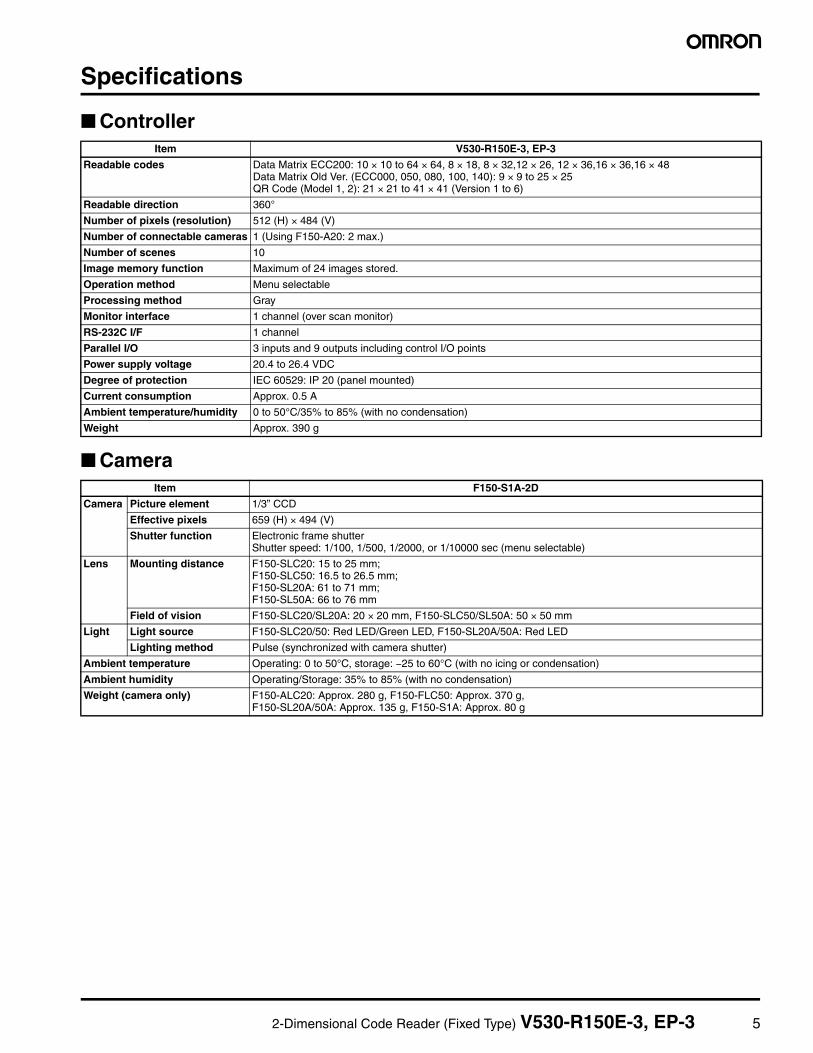
Specifications
Controller
Camera
Item V530-R150E-3, EP-3
Readable codes Data Matrix ECC200: 10 × 10 to 64 × 64, 8 × 18, 8 × 32,12 × 26, 12 × 36,16 × 36,16 × 48Data Matrix Old Ver. (ECC000, 050, 080, 100, 140): 9 × 9 to 25 × 25QR Code (Model 1, 2): 21 × 21 to 41 × 41 (Version 1 to 6)
Readable direction 360°
Number of pixels (resolution) 512 (H) × 484 (V)
Number of connectable cameras 1 (Using F150-A20: 2 max.)
Number of scenes 10
Image memory function Maximum of 24 images stored.
Operation method Menu selectable
Processing method Gray
Monitor interface 1 channel (over scan monitor)
RS-232C I/F 1 channel
Parallel I/O 3 inputs and 9 outputs including control I/O points
Power supply voltage 20.4 to 26.4 VDC
Degree of protection IEC 60529: IP 20 (panel mounted)
Current consumption Approx. 0.5 A
Ambient temperature/humidity 0 to 50°C/35% to 85% (with no condensation)
Weight Approx. 390 g
Item F150-S1A-2D
Camera Picture element 1/3” CCD
Effective pixels 659 (H) × 494 (V)
Shutter function Electronic frame shutterShutter speed: 1/100, 1/500, 1/2000, or 1/10000 sec (menu selectable)
Lens Mounting distance F150-SLC20: 15 to 25 mm; F150-SLC50: 16.5 to 26.5 mm; F150-SL20A: 61 to 71 mm; F150-SL50A: 66 to 76 mm
Field of vision F150-SLC20/SL20A: 20 × 20 mm, F150-SLC50/SL50A: 50 × 50 mm
Light Light source F150-SLC20/50: Red LED/Green LED, F150-SL20A/50A: Red LED
Lighting method Pulse (synchronized with camera shutter)
Ambient temperature Operating: 0 to 50°C, storage: −25 to 60°C (with no icing or condensation)
Ambient humidity Operating/Storage: 35% to 85% (with no condensation)
Weight (camera only) F150-ALC20: Approx. 280 g, F150-FLC50: Approx. 370 g,F150-SL20A/50A: Approx. 135 g, F150-S1A: Approx. 80 g

6 2-Dimensional Code Reader (Fixed Type) V530-R150E-3, EP-3
Two-Camera Unit MonitorItem F150-A20
Number of connectable cameras
2
Camera mode 2-camera selectableSingle, independent (camera 0/1)
Power supply voltage 20.4 to 26.4 VDC
Current consumption Approx. 0.3 A
Ambient temperature Operating: 0 to 50°Cstorage: −25 to 60°C (with no icing or condensation)
Ambient humidity Operating/Storage: 35% to 85%(with no condensation)
Weight (2-camera unit only)
Approx. 220 g
Item
Liquid Crystal Monitor
Video Monitor
F150-M05L-2D F150-M09-2D
Size 5.5 inches 9 inches
Type Liquid crystal color TFT CRT monochrome
Resolution 320 × 240 dots 800 TV lines min. (at center)
Input signal NTSC composite video (1.0 V/75 Ω)
Power supply voltage
20.4 to 26.4 VDC 100 to 240 VAC (−15%, +10%)
Current consumption
Approx. 700 mA Approx. 200 mA
Ambient temperature
Operating: 0 to 50°Cstorage: −25 to 60°C(with no icing or con-densation)
Operating: −10 to 50°Cstorage: −20 to 65°C(with no icing or con-densation)
Ambient humidity
Operating/Storage: 35% to 85%(with no condensation)
10% to 90% (with no condensation)
Weight (monitor only)
Approx. 1 kg Approx. 4.5 kg

2-Dimensional Code Reader (Fixed Type) V530-R150E-3, EP-3 7
System ConfigurationCameras
F150-S1A-2D Camera
Power Supply
Synchronous Sensor
RS-232C
F150-KP-2D 2M Console Cable length: 2
ProgrammableController
F150-SLC20 Camera with Intelligent Light Source (Field of vision: 20 mm)
Recommended Power Supply:OMRON S82K-01524 or S82K-05024 Note: Use specified voltage.
F150-SLC50 Camera with Intelligent Light Source (Field of vision: 50 mm)
V530-R150E-3, EP-3 Controller
F150-SL20A Camera with Light Source (Field of vision: 20 mm) F150-SL50A Camera with Light Source (Field of vision: 50 mm)
F150-VS-2D Camera Cable (3 m)
F150-VM-2D Monitor Cable (2 m)
Personal Computer
BNC Jack (Provided with the F150-VM-2D)
Monitors
F150-M05L-2D Liquid Crystal Monitor (pin input)
F150-M09-2D Video Monitor (BNC input)
Note: In addition to the F150-M05L-2D and F150-M09-2D, NTSC monitors with external video input terminals can be used. F150-M09-2D does not confrom to EC Directive.
Products indicated with a star () are specially designed for use with the V530-R150E-3 Controller and V530-R150EP-3 Controller. They cannot be substituted with other products.
Refer to page B-8 concerning the use of this camera.
Note: If the field of vision does not match the size of the target object you can use an ordinary CCTV lens and lighting.
F150-VS-2D Camera Cable
F150-A20 Two-Camera Unit
Camera Unit Cable (15 cm) (Provided with the F150-A20)

8 2-Dimensional Code Reader (Fixed Type) V530-R150E-3, EP-3
Lighting MethodsSelect the appropriate lighting method for the material of the marked object.
Back LightingCodes on transparent objects such as glass PCBs can be read bydetecting the contrast between transmitted and blocked light.
Applications: Transparent objects such as LCD glass
Reflected Lighting
Ring Lighting
For codes printed onto paper or other light-diffusing objects, ringlights can be used to illuminate the marked object. The difference inthe reflection factors of the background and the marking enables sta-ble detection.
Applications: Paper labels and corrugated cardboard
Oblique LightingRing Lighting Close to the Marked Object
For codes inscribed with a laser marker onto PCBs and other rela-tively glossy surfaces, oblique lighting provides stable detection bydistinguishing between regular and diffuse reflected light.
Applications: Direct marking on PCBs and electronic parts
Coaxial Lighting
For codes marked directly onto wafers and other mirror-like surfaces,a stable image with few shadows from surface irregularities can beobtained from the marked object by using coaxial lighting, because itdetects only regular reflected light. (The surface of the object must beperpendicular to the optical axis.)
Applications: Mirror-like objects such as wafers
Camera
Glass
Light source
Marked object (2-dimensional code)
Camera
Light source
Marked object (2-dimensional code)
Paper
PCB
Camera
Light source
Marked object (2-dimensional code)
Half mirror
Wafer
Camera
Marked object (2-dimensional code)
Light source

2-Dimensional Code Reader (Fixed Type) V530-R150E-3, EP-3 9
Data CapacityData Matrix ECC200
The relation between matrix size (number of cells) and data capacityis shown in the table below. In this example, the matrix size is 12 × 12cells.
QR Code Model 2
The relation between matrix size (number of cells) and data capacityis shown in the table below. In this example, the matrix size is 21 × 21cells.
Note: 1. Maximum Data CapacityThe maximum amount of data that can be stored in a code varies with the code size. In other words, if there is a large amount of data tobe stored, then the code size must also be large. The maximum data capacity will also vary with the type of characters used. With a QRCode or Data Matrix, the numeric capacity (numbers only) is larger than the alpha numeric capacity (numbers and letters), which is inturn larger than the Japanese Kanji (Shift JIS) capacity. The order and combinations of different characters also affects the data capacity.
2. The matrix size of a QR Code is indicated by the version. Version 1 indicates that a QR Code contains (the minimum) 21 cells both hor-izontally and vertically. The larger the version number, the larger the number of cells per side.
Matrix size
Maximum data capacity
Num-bers
Alpha-numeric charac-
ters
Symbols Japa-nese Kanji (Shift JIS)
JIS8
10 × 10 6 3 3 --- 1
12 × 12 10 6 5 1 3
14 × 14 16 10 9 3 6
16 × 16 24 16 14 5 10
18 × 18 36 25 22 8 16
20 × 20 44 31 28 10 20
22 × 22 60 43 38 14 28
24 × 24 72 52 46 17 34
26 × 26 88 64 57 21 42
32 × 32 124 91 81 30 60
36 × 36 172 127 113 42 84
40 × 40 228 169 150 56 112
44 × 44 288 214 190 71 142
48 × 48 348 259 230 86 172
52 × 52 408 304 270 101 202
64 × 64 560 418 372 139 278
8 × 18 10 6 5 1 3
8 × 32 20 13 12 4 8
12 × 26 32 22 20 7 14
12 × 36 44 31 28 10 20
16 × 36 64 46 41 15 30
16 × 48 98 72 64 23 47
12 cells
12 cells
Matrix size (version)
Error correc-
tion
Maximum data capacity
Num-bers
Alphanu-meric
charac-ters
(upper case only)
JIS8 Japa-nese Kanji (Shift JIS)
21 × 21 (version 1)
L (7%) 41 25 17 10
M (15%) 34 20 14 8
Q (25%) 27 16 11 7
H (30%) 17 10 7 4
25 × 25 (version 2)
L (7%) 77 47 32 20
M (15%) 63 38 26 16
Q (25%) 48 29 20 12
H (30%) 34 20 14 8
29 × 29 (version 3)
L (7%) 127 77 53 32
M (15%) 101 61 42 26
Q (25%) 77 47 32 20
H (30%) 58 35 24 15
33 × 33 (version 4)
L (7%) 187 114 78 48
M (15%) 149 90 62 38
Q (25%) 111 67 46 28
H (30%) 82 50 34 21
37 × 37 (version 5)
L (7%) 255 154 106 65
M (15%) 202 122 84 52
Q (25%) 144 87 60 37
H (30%) 106 64 44 27
41 × 41 (version 6)
L (7%) 322 195 134 82
M (15%) 255 154 106 65
Q (25%) 178 108 74 45
H (30%) 139 84 58 36
7 cells
7 cells 14 cells
7 cells
7 cells
10 2-Dimensional Code Reader (Fixed Type) V530-R150E-3, EP-3
Cameras with Light Source
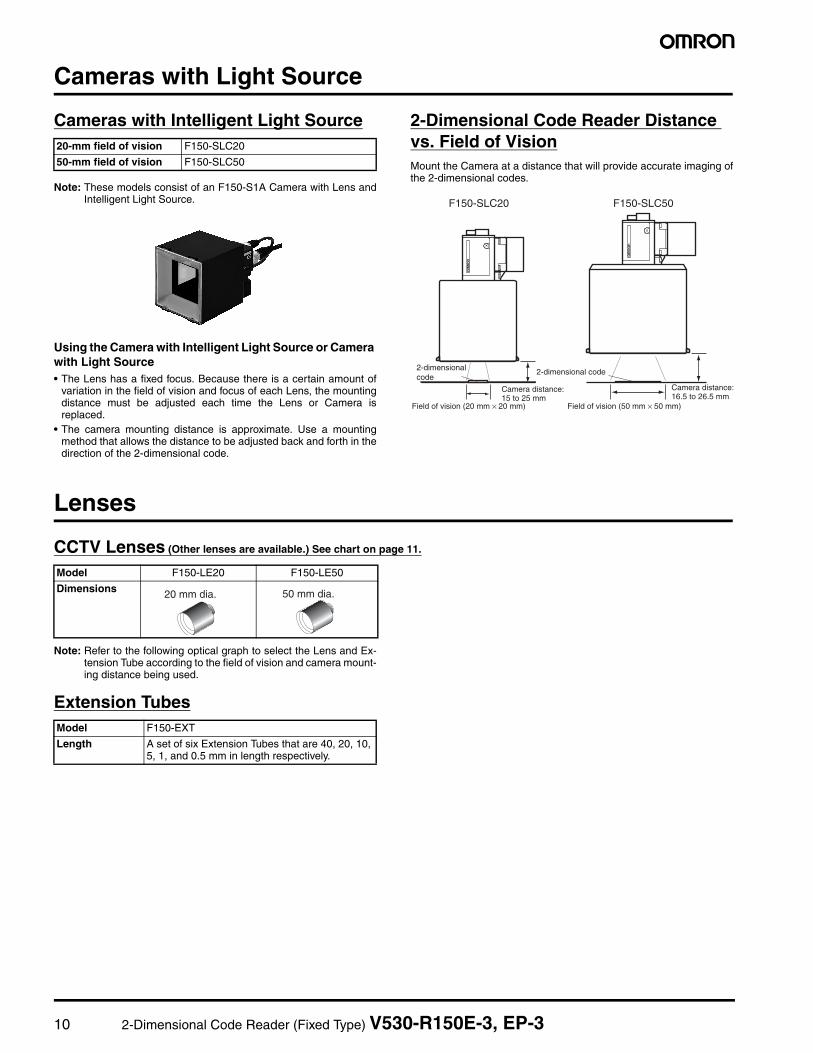
Cameras with Intelligent Light Source
Note: These models consist of an F150-S1A Camera with Lens andIntelligent Light Source.
Using the Camera with Intelligent Light Source or Camera with Light Source• The Lens has a fixed focus. Because there is a certain amount of
variation in the field of vision and focus of each Lens, the mountingdistance must be adjusted each time the Lens or Camera isreplaced.
• The camera mounting distance is approximate. Use a mountingmethod that allows the distance to be adjusted back and forth in thedirection of the 2-dimensional code.
2-Dimensional Code Reader Distance vs. Field of VisionMount the Camera at a distance that will provide accurate imaging ofthe 2-dimensional codes.
Lenses
CCTV Lenses (Other lenses are available.) See chart on page 11.
Note: Refer to the following optical graph to select the Lens and Ex-tension Tube according to the field of vision and camera mount-ing distance being used.
Extension Tubes
20-mm field of vision F150-SLC20
50-mm field of vision F150-SLC50
F150-SLC20 F150-SLC50
2-dimensional code
2-dimensional code
Camera distance:15 to 25 mm
Camera distance:16.5 to 26.5 mm
Field of vision (20 mm × 20 mm) Field of vision (50 mm × 50 mm)
Model F150-LE20 F150-LE50
Dimensions 20 mm dia. 50 mm dia.
Model F150-EXT
Length A set of six Extension Tubes that are 40, 20, 10, 5, 1, and 0.5 mm in length respectively.

2-Dimensional Code Reader (Fixed Type) V530-R150E-3, EP-3 11
Optical GraphPoint: Based on the necessary field of vision and workpiece, select the Lens and Extension Tube to suit the working distance (WD). Lengthening the Extension Tube lowers the brightness, and increasing distance WD increases the depth of field.
Note: Slight differences exist between cameras. When mounting the Lens, provide a means of adjusting the camera mounting distance.
Reading the Optical GraphThe X axis of the graph shows field of vision L in millimeters, and theY axis shows the camera mounting distance A in millimeters.The curves on the graph indicate different Lenses, and the “t” valuesindicate the lengths of the Extension Tubes.
1515
1
1
5
3535 5555
F150-L50 (50 mm)
16 mm
0
50
100
150
200
250
300
350
400
450
500
0 20 30 40
1
1
5
1
5
1015
20
5
10
1520
2530
5101
Optical Graph
Field of vision L (mm)
Wor
king
dis
tanc
e (m
m)
Note: The values in the graph indicate the length (in mm) of the Extension tubes.
35 to 55
F150-L25 (25 mm)
F150-L16 (16 mm)
F150-L12 (12 mm)
Camera
Extension Tube
Lenses
Field of vision L (mm)
Working distance WD (mm)

12 2-Dimensional Code Reader (Fixed Type) V530-R150E-3, EP-3
DimensionsNote: All units are in millimeters unless otherwise indicated.
2-Dimensional Code Reader
V530-R150E-3, V530-R150EP-3
Camera
F150-SLC20 (Camera with F150-LTC20 Intelligent Light Source)
F150-SLC50 (Camera with F150-LTC50 Intelligent Light Source)
F150-S1A-2D (Camera only)
Console
F150-KP-2D
4.1
100 90
130
120
77.6
50120
Four, 4.5 dia.
2.5
12 122.5
12 12 16.7596.25
6.7520
70
70
40
73 40 (85)
86.25
42.5
Mounting dimensions
Two, M4 holes with depth of 10
1/4-20UNC with depth of 10
2.5
2.5
90
16 16.75
6.7520
60
16
16 16
90
52.5
80 40 (85)
103.25
93.25
Mounting dimensions
Two, M4 holes with depth of 10
1/4-20UNC with depth of 10
8
1.5F150 connector
14.5
2021.25
16.75
6.75
25
15.5
11
F150 lightconnector
4037
48(40) 31
30.5
31.25
Mounting dimensions
Two, M4 holes with depth of 10
1/4-20UNC with depth of 10
12 dia.
5
131.5
10
12.5
2000
87
50
23

2-Dimensional Code Reader (Fixed Type) V530-R150E-3, EP-3 13
Two-Camera Unit
F150-A20
Liquid Crystal Monitor
F150-M05L-2D
Video Monitor
F150-M09-2D
3.3
56±0.2
100±0.2 100 90 110
50
56
66
(mounting holes)
Mounting holes
Two, M4
Two, 4.5 dia.
(155)
50 min
(46 max)
(5.5)
42.2
133.5
175.5
+0.5mm 0
+0.5mm 0
143 132(145)
174
185(100)
Mounting bracket
Panel cut diagram
Allowable panel thick-ness for mounting: 1.6 to 4.8
F150-VM Monitor CableTolerance: ±1 mm Dimensions inside parenthe-ses ( ) are reference values.
522
50
222
233
143
190
250
160
ALL DIMENSIONS SHOWN ARE IN MILLIMETERS.
To convert millimeters into inches, multiply by 0.03937. To convert grams into ounces, multiply by 0.03527.

14 2-Dimensional Code Reader (Fixed Type) V530-R150E3, EP-3
Terms and ConditionsWARRANTY, LIMITATIONS OF LIABILITYWARRANTY OMRON’s exclusive warranty is that the products arefree from defects in materials and workmanship for a period of oneyear (or other period if specified) from date of sale by OMRON.
OMRON MAKES NO WARRANTY OR REPRESENTATION,EXPRESS OR IMPLIED, REGARDING NON-INFRINGEMENT,MERCHANTABILITY OR FITNESS FOR PARTICULAR PURPOSEOF THE PRODUCTS. ANY BUYER OR USER ACKNOWLEDGESTHAT IT ALONE HAS DETERMINED THAT THE PRODUCTS WILLSUITABLY MEET THE REQUIREMENTS OF THEIR INTENDEDUSE. OMRON DISCLAIMS ALL OTHER WARRANTIES, EXPRESSOR IMPLIED.
LIMITATIONS OF LIABILITY OMRON SHALL NOT BE RESPONSI-BLE FOR SPECIAL, INDIRECT OR CONSEQUENTIAL DAMAGES,LOSS OF PROFITS OR COMMERCIAL LOSS IN ANY WAY CON-NECTED WITH THE PRODUCTS, WHETHER SUCH CLAIM ISBASED ON CONTRACT, WARRANTY, NEGLIGENCE OR STRICTLIABILITY.
In no event shall responsibility of OMRON for any act exceed the indi-vidual price of the product on which liability is asserted.
IN NO EVENT SHALL OMRON BE RESPONSIBLE FOR WAR-RANTY, REPAIR OR OTHER CLAIMS REGARDING THE PROD-UCTS UNLESS OMRON’S ANALYSIS CONFIRMS THAT THEPRODUCTS WERE PROPERLY HANDLED, STORED, INSTALLEDAND MAINTAINED AND NOT SUBJECT TO CONTAMINATION,ABUSE, MISUSE, OR INAPPROPRIATE MODIFICATION ORREPAIR.
APPLICATION CONSIDERATIONSSUITABILITY FOR USE OMRON shall not be responsible for confor-mity with any standards, codes or regulations which apply to thecombination of the product in the customer's application or use of theproduct.
At the customer's request, OMRON will provide applicable third partycertification documents identifying ratings and limitations of usewhich apply to the product. This information by itself is not sufficientfor a complete determination of the suitability of the product in combi-nation with the end product, machine, system, or other application oruse.
The following are some examples of applications for which particularattention must be given. This is not intended to be an exhaustive list
of all possible uses of this product, nor is it intended to imply that theuses listed may be suitable for this product:
• Outdoor use, uses involving potential chemical contamination orelectrical interference, or conditions or uses not described in thiscatalog.
• Nuclear energy control systems, combustion systems, railroad sys-tems, aviation systems, medical equipment, amusement machines,vehicles, safety equipment, and installations subject to separateindustry or government regulations.
• Systems, machines and equipment that could present a risk to lifeor property.
Please know and observe all prohibitions of use applicable to thisproduct.
NEVER USE THE PRODUCT FOR AN APPLICATION INVOLVINGSERIOUS RISK TO LIFE OR PROPERTY WITHOUT ENSURINGTHAT THE SYSTEM AS A WHOLE HAS BEEN DESIGNED TOADDRESS THE RISKS, AND THAT THE OMRON PRODUCT ISPROPERLY RATED AND INSTALLED FOR THE INTENDED USEWITHIN THE OVERALL EQUIPMENT OR SYSTEM.
PROGRAMMABLE PRODUCTS OMRON shall not be responsiblefor the user’s programming of a programmable product, or any con-sequence thereof.
DISCLAIMERSPERFORMANCE DATA Performance data given in this catalog isprovided as a guide for the user in determining suitability and doesnot constitute a warranty. It may represent the result of OMRON’stest conditions, and the user must correlate it to actual applicationrequirements. Actual performance is subject to the OMRON War-ranty and Limitations of Liability.
CHANGE IN SPECIFICATIONS Product specifications and accesso-ries may be changed at any time based on improvements and otherreasons. It is our practice to change part numbers when publishedratings or features are changed, or when significant constructionchanges are made. However, some specifications of the product maybe changed without any notice. When in doubt, special part numbersmay be assigned to fix or establish key specifications for your appli-cation. Please consult with your OMRON representative at any timeto confirm actual specifications of purchased product.
ERRORS AND OMISSIONS The information in this catalog hasbeen carefully checked and is believed to be accurate; however, noresponsibility is assumed for clerical, typographical or proofreadingerrors, or omissions.
OMRON ON-LINEGlobal - http://www.omron.comUSA - http://www.omron.com/oeiCanada - http://www.omron.ca
ALL DIMENSIONS SHOWN ARE IN MILLIMETERS. To convert millimeters into inches, divide by 25.4
Cat. No. GC RFID 4 Printed in USA
OMRON CANADA, INC.885 Milner AvenueToronto, Ontario M1B 5V8
416-286-6465
OMRON ELECTRONICS LLCOne Commerce DriveSchaumburg, IL 60173
847-843-7900For US technical support or other inquiries:
800-556-6766
5/03 Specifications subject to change without notice
Complete terms and conditions for product purchase and use are on Omron’s website atwww.omron.com/oei – under the “About Us” tab, in the Legal Matters section.