Embed Size (px)
DESCRIPTION
Among other requirements, you should upload something that is not already on Scribd and that you have permission to use. The best way to make sure what you are uploading will meet our quality standards is to upload something you wrote yourself, which will always be accepted
Citation preview
CENTROID™
M-SERIES Operator's Manual
CNC11 Version 3.08 120824
U.S. Patent #6490500 © 2012 Centroid Corp. Howard, PA 16841

READ THIS MANUAL BEFORE USING THIS PRODUCT.FAILURE TO FOLLOW THE INSTRUCTIONS AND SAFETY
PRECAUTIONS IN THIS MANUAL CAN RESULT INSERIOUS INJURY OR DEATH.
All operators and service personnel must read this manual before operatingCENTROID CNC control equipment and all connected machine tools.
Keep this manual in a safe location for future reference.
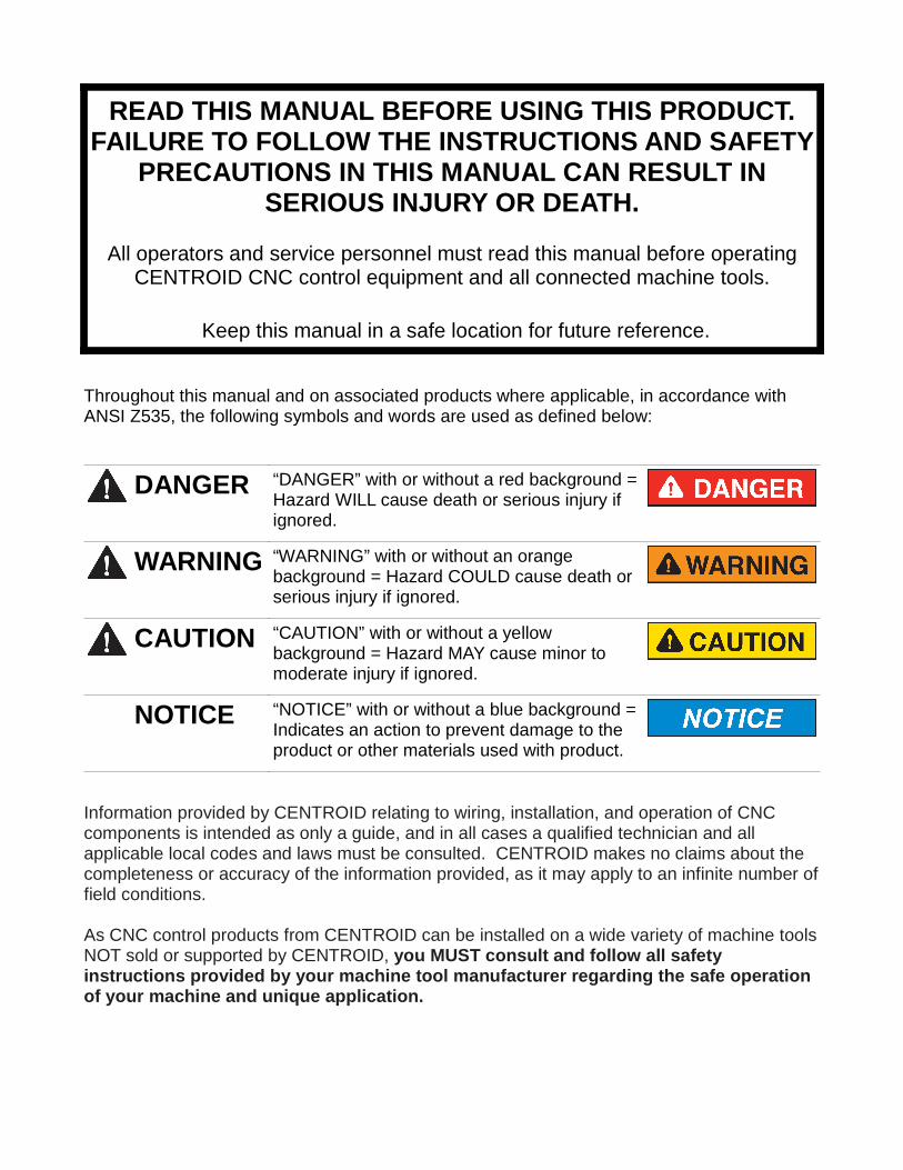
Throughout this manual and on associated products where applicable, in accordance withANSI Z535, the following symbols and words are used as defined below:
DANGER “DANGER” with or without a red background =Hazard WILL cause death or serious injury ifignored.
WARNING “WARNING” with or without an orangebackground = Hazard COULD cause death orserious injury if ignored.
CAUTION “CAUTION” with or without a yellowbackground = Hazard MAY cause minor tomoderate injury if ignored.
NOTICE “NOTICE” with or without a blue background =Indicates an action to prevent damage to theproduct or other materials used with product.
Information provided by CENTROID relating to wiring, installation, and operation of CNCcomponents is intended as only a guide, and in all cases a qualified technician and allapplicable local codes and laws must be consulted. CENTROID makes no claims about thecompleteness or accuracy of the information provided, as it may apply to an infinite number offield conditions.
As CNC control products from CENTROID can be installed on a wide variety of machine toolsNOT sold or supported by CENTROID, you MUST consult and follow all safetyinstructions provided by your machine tool manufact urer regarding the safe operationof your machine and unique application.
CENTROID CNC controls provide facilities for a required Emergency Stop circuit which canbe used to completely disable your machine tool in the event of an emergency or unsafecondition. Proper installation of your CNC control MUST includ e the necessary wiringto disable ALL machine tool movement when the Emerg ency Stop button is pressed.This includes machine, servo motors, tool changers, coolant pumps, and any other movingparts. DO NOT disable or alter any safety feature of your machine or CNC control.
Never alter or remove any safety sign or symbol fro m your machine or CNC controlcomponents. If signs become damaged or worn, or if additional signs are needed toemphasize a particular safety issue, contact your dealer or CENTROID.
CNC Control Operating Specifications
Minimum Maximum
Operating Temperature 40°F (5°C) 104°F (40°C)
Ambient Humidity 30% relative, non-condensing 90% relative, non-condensing
Altitude 0 Ft. (Sea Level) 6000 Ft. (1830m)
Input Voltage (110, 220, 440 VAC,System Dependent)
-10% of Specified System InputVoltage
+10% of Specified System InputVoltage
Note: Your machine may have operating conditions different than those shown above. Always consult yourmachine manual and documentation.
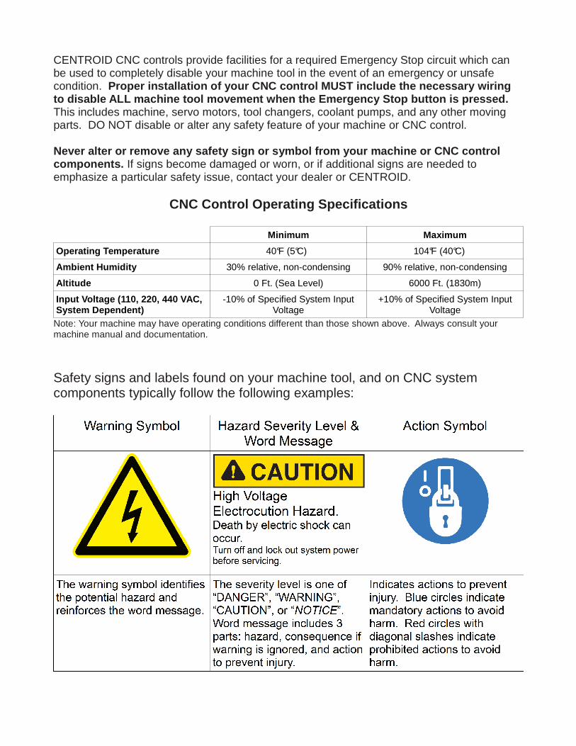
Safety signs and labels found on your machine tool, and on CNC systemcomponents typically follow the following examples:
CNC Machine Tool Safety
•All machine tools contain hazards from rotating parts; movement of belts, pulleys, gears, and chains;high voltage electricity; compressed air; noise; and airborne dust, chips, swarf, coolant, and lubricants.Basic safety precautions must be followed to reduce the risk of personal injury and property damage.
•Your local safety codes and regulations must be consulted before installation and operation of yourmachine and CENTROID CNC control. Should a safety concern arise, always contact your dealer orservice technician immediately.
•Access to all dangerous areas of the machine must be restricted while the machine is in use. Ensurethat all safety guards and doors are properly in place during use. Automatically controlled machinetools may start, stop, or move suddenly at any time . Do not enter the machining area when themachine is in motion; death or severe injury may re sult.
•Personal protective equipment, particularly ANSI-approved impact safety glasses and OSHA-approved hearing protection must be used. Proper handling, storage, use, and disposal of materialsin accordance with manufacturer's instructions and Material Safety Data Sheets (MSDS, or your localequivalent) must be followed.
•DO NOT operate your machine or CNC control in explosive atmospheres or in environmentalconditions outside of the manufacturer's specified ranges. Electrical power must meet thespecifications provided by your machine and CNC control manufacturer.
•DO NOT operate your machine or CNC control if any safety systems are damaged or missing.Excessively scratched or damaged windows and guards must be replaced.
•ONLY authorized personnel should be allowed to operate the machine and CNC control. Improperoperation can cause injury, death, and machine or control damage, and may void applicablewarranties.
•All electrical enclosures and panels MUST be closed and secured at all times except duringinstallation and service. Only qualified electricians and service personnel should have access to theselocations. Hazards arising from high voltage electricity and heat exist in the control cabinet, and mayexist even after the main disconnect is turned OFF.
•Improperly clamped or fixtured parts; improperly secured tooling; and broken parts, fixtures, andtooling resulting from machining operations at unsafe feedrates and speeds may result in projectilesbeing ejected from your machine, even through safety systems such as guards and doors. Alwaysfollow safe and reasonable machining practices and follow all safety precautions provided by yourtooling and machine manufacturer.
•Ultimate responsibility for safe operation and maintenance of your machine and CNC control restswith shop owners and machine operators. Before performing any work or maintenance all individualsshould be thoroughly acquainted with the safe operation of BOTH machine tool AND CNC control.
•Shop owners and operators are responsible for ensuring that shop and machine safety systems suchas Emergency Stop and fire suppression systems are present and functioning properly, as required bylocal codes and regulations.

CNC Control Warning Labels
High Voltage ElectrocutionHazard.Death by electric shock can occur.Turn off and lock out system power beforeservicing.
High Voltage ElectrocutionHazard.Death by electric shock can occur.Turn off and lock out system power beforeservicing.
TABLE OF CONTENTS CHAPTER 1 - Introduction Window Description 1-1 Conventions 1-3 Machine Home 1-4 Mill M and G Codes 1-5 Software Unlocks 1-6 CHAPTER 2 - Operator Panels M-Series Jog Panel 2-1 Keyboard Jog Panel 2-5 Keyboard Shortcut Keys 2-7 CHAPTER 3 – CNC Software Main Screen Option Descriptions 3-1 CHAPTER 4 - Part Setup Operation Description 4-2 Part Setup Examples 4-4 Work Coordinate Systems Configuration 4-6 Coordinate Systems Rotation 4-7 Transformed WCS 4-8 CHAPTER 5 - Tool Setup Offset Library 5-1 Automatic Tool Measurement 5-3 Setting up Tool Height Offsets 5-4 Tool Library 5-5 CHAPTER 6 – Running a Job Job Run Screen with G-code Display 6-1 Run-Time Graphics 6-2 Canceling a Job in Progress 6-2 Resuming a Canceled Job 6-3 Run Menu 6-3 Power Feed 6-5 CHAPTER 7 - The Utility Menu F2 – Update, F3 – Backup, F4 – Restore 7-1 F5 - File Ops. 7-2 F6 – User Maint, F7 – Report 7-3 F8 – Options, F9 – Logs 7-3 CHAPTER 8 – Digitize Grid Digitize 8-2 Radial Digitize 8-6 Contour Digitize 8-10 Wall Following Digitizing 8-13 Dig to CAD 8-15 CHAPTER 9 - Probing Part Setup with Probing 9-1 Calibrating the Probe Tip Diameter 9-2 Probing Cycles 9-2 Probe Parameters 9-7 DSP Probe Parameters 9-8
CHAPTER 10 - Intercon Software Intercon Main Screen 10-1 File Menu 10-2 Rapid Traverse 10-7 Linear Mill 10-8 Arc Mill 10-10 Tool Functions 10-12 Canned Cycles 10-13
Drilling 10-16 Chip Breaking 10-17 Deep Hole Drilling 10-19 Boring 10-20 Tapping 10-22 Facing 10-24 Rectangular Pocket 10-25 Circular Pocket 10-27 Rectangular/Circular Frame Milling 10-29 Thread Milling 10-31 Cleanout 10-33
Subprograms 10-36 Repeat to Depth 10-38 Repeat 10-39 Mirror 10-40 Rotate 10-41
Graphics 10-42 Math Help 10-45 Importing DXF files 10-52 Intercon Tutorials 10-59 CHAPTER 11 – CNC Program Codes Miscellaneous CNC Program Symbols 11-1 User and System Variables 11-5 Advanced Macro Statements 11-8 CHAPTER 12 - G-codes G-Code Quick Reference 12-1 G-Code Descriptions 12-2 CHAPTER 13 - M functions M function Quick Reference 13-1 Customizable M functions 13-2 M function Descriptions 13-3 CHAPTER 14 – Configuration Password 14-1 Control Configuration 14-2 User Specified Paths 14-3 Machine Configuration 14-4 Machine Parameters 14-8 PID Menu 14-42 DSP Probe Configuration 14-45 Smoothing 14-47 CHAPTER 15 – CNC Software Messages CNC Software Message Descriptions 15-1

M-Series Operator’s Manual 8/24/12 1-1
Chapter 1 Introduction
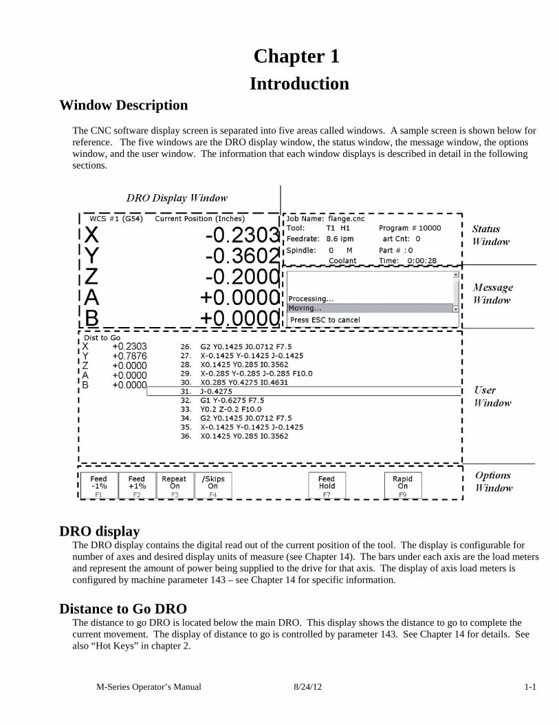
Window Description The CNC software display screen is separated into five areas called windows. A sample screen is shown below for reference. The five windows are the DRO display window, the status window, the message window, the options window, and the user window. The information that each window displays is described in detail in the following sections.
DRO display The DRO display contains the digital read out of the current position of the tool. The display is configurable for number of axes and desired display units of measure (see Chapter 14). The bars under each axis are the load meters and represent the amount of power being supplied to the drive for that axis. The display of axis load meters is configured by machine parameter 143 – see Chapter 14 for specific information.
Distance to Go DRO The distance to go DRO is located below the main DRO. This display shows the distance to go to complete the current movement. The display of distance to go is controlled by parameter 143. See Chapter 14 for details. See also “Hot Keys” in chapter 2.
M-Series Operator’s Manual 8/24/12 1-2
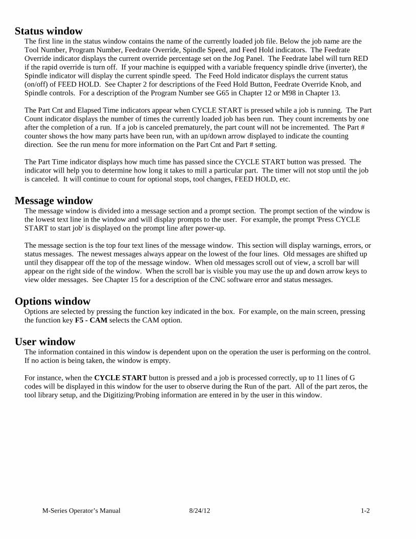
Status window The first line in the status window contains the name of the currently loaded job file. Below the job name are the Tool Number, Program Number, Feedrate Override, Spindle Speed, and Feed Hold indicators. The Feedrate Override indicator displays the current override percentage set on the Jog Panel. The Feedrate label will turn RED if the rapid override is turn off. If your machine is equipped with a variable frequency spindle drive (inverter), the Spindle indicator will display the current spindle speed. The Feed Hold indicator displays the current status (on/off) of FEED HOLD. See Chapter 2 for descriptions of the Feed Hold Button, Feedrate Override Knob, and Spindle controls. For a description of the Program Number see G65 in Chapter 12 or M98 in Chapter 13. The Part Cnt and Elapsed Time indicators appear when CYCLE START is pressed while a job is running. The Part Count indicator displays the number of times the currently loaded job has been run. They count increments by one after the completion of a run. If a job is canceled prematurely, the part count will not be incremented. The Part # counter shows the how many parts have been run, with an up/down arrow displayed to indicate the counting direction. See the run menu for more information on the Part Cnt and Part # setting. The Part Time indicator displays how much time has passed since the CYCLE START button was pressed. The indicator will help you to determine how long it takes to mill a particular part. The timer will not stop until the job is canceled. It will continue to count for optional stops, tool changes, FEED HOLD, etc.
Message window The message window is divided into a message section and a prompt section. The prompt section of the window is the lowest text line in the window and will display prompts to the user. For example, the prompt 'Press CYCLE START to start job' is displayed on the prompt line after power-up. The message section is the top four text lines of the message window. This section will display warnings, errors, or status messages. The newest messages always appear on the lowest of the four lines. Old messages are shifted up until they disappear off the top of the message window. When old messages scroll out of view, a scroll bar will appear on the right side of the window. When the scroll bar is visible you may use the up and down arrow keys to view older messages. See Chapter 15 for a description of the CNC software error and status messages.
Options window Options are selected by pressing the function key indicated in the box. For example, on the main screen, pressing the function key F5 - CAM selects the CAM option.
User window The information contained in this window is dependent upon on the operation the user is performing on the control. If no action is being taken, the window is empty. For instance, when the CYCLE START button is pressed and a job is processed correctly, up to 11 lines of G codes will be displayed in this window for the user to observe during the Run of the part. All of the part zeros, the tool library setup, and the Digitizing/Probing information are entered in by the user in this window.
M-Series Operator’s Manual 8/24/12 1-3
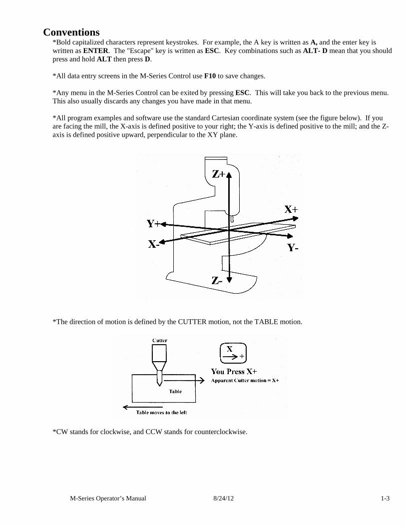
Conventions *Bold capitalized characters represent keystrokes. For example, the A key is written as A, and the enter key is written as ENTER. The "Escape" key is written as ESC. Key combinations such as ALT- D mean that you should press and hold ALT then press D. *All data entry screens in the M-Series Control use F10 to save changes. *Any menu in the M-Series Control can be exited by pressing ESC. This will take you back to the previous menu. This also usually discards any changes you have made in that menu. *All program examples and software use the standard Cartesian coordinate system (see the figure below). If you are facing the mill, the X-axis is defined positive to your right; the Y-axis is defined positive to the mill; and the Z-axis is defined positive upward, perpendicular to the XY plane.
*The direction of motion is defined by the CUTTER motion, not the TABLE motion.
*CW stands for clockwise, and CCW stands for counterclockwise.
M-Series Operator’s Manual 8/24/12 1-4
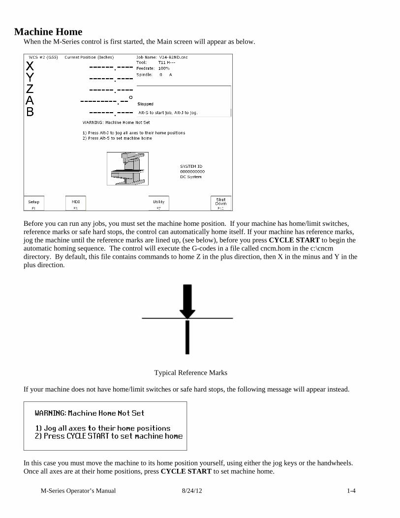
Machine Home When the M-Series control is first started, the Main screen will appear as below.
Before you can run any jobs, you must set the machine home position. If your machine has home/limit switches, reference marks or safe hard stops, the control can automatically home itself. If your machine has reference marks, jog the machine until the reference marks are lined up, (see below), before you press CYCLE START to begin the automatic homing sequence. The control will execute the G-codes in a file called cncm.hom in the c:\cncm directory. By default, this file contains commands to home Z in the plus direction, then X in the minus and Y in the plus direction.
Typical Reference Marks
If your machine does not have home/limit switches or safe hard stops, the following message will appear instead.
In this case you must move the machine to its home position yourself, using either the jog keys or the handwheels. Once all axes are at their home positions, press CYCLE START to set machine home.
M-Series Operator’s Manual 8/24/12 1-5
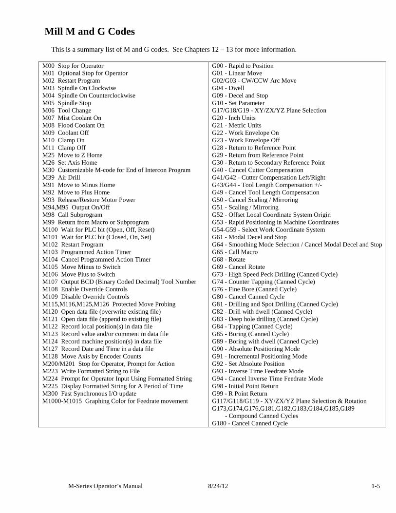
Mill M and G Codes This is a summary list of M and G codes. See Chapters 12 – 13 for more information.
M00 Stop for Operator M01 Optional Stop for Operator M02 Restart Program M03 Spindle On Clockwise M04 Spindle On Counterclockwise M05 Spindle Stop M06 Tool Change M07 Mist Coolant On M08 Flood Coolant On M09 Coolant Off M10 Clamp On M11 Clamp Off M25 Move to Z Home M26 Set Axis Home M30 Customizable M-code for End of Intercon Program M39 Air Drill M91 Move to Minus Home M92 Move to Plus Home M93 Release/Restore Motor Power M94,M95 Output On/Off M98 Call Subprogram M99 Return from Macro or Subprogram M100 Wait for PLC bit (Open, Off, Reset) M101 Wait for PLC bit (Closed, On, Set) M102 Restart Program M103 Programmed Action Timer M104 Cancel Programmed Action Timer M105 Move Minus to Switch M106 Move Plus to Switch M107 Output BCD (Binary Coded Decimal) Tool Number M108 Enable Override Controls M109 Disable Override Controls M115,M116,M125,M126 Protected Move Probing M120 Open data file (overwrite existing file) M121 Open data file (append to existing file) M122 Record local position(s) in data file M123 Record value and/or comment in data file M124 Record machine position(s) in data file M127 Record Date and Time in a data file M128 Move Axis by Encoder Counts M200/M201 Stop for Operator, Prompt for Action M223 Write Formatted String to File M224 Prompt for Operator Input Using Formatted String M225 Display Formatted String for A Period of Time M300 Fast Synchronous I/O update M1000-M1015 Graphing Color for Feedrate movement
G00 - Rapid to Position G01 - Linear Move G02/G03 - CW/CCW Arc Move G04 - Dwell G09 - Decel and Stop G10 - Set Parameter G17/G18/G19 - XY/ZX/YZ Plane Selection G20 - Inch Units G21 - Metric Units G22 - Work Envelope On G23 - Work Envelope Off G28 - Return to Reference Point G29 - Return from Reference Point G30 - Return to Secondary Reference Point G40 - Cancel Cutter Compensation G41/G42 - Cutter Compensation Left/Right G43/G44 - Tool Length Compensation +/- G49 - Cancel Tool Length Compensation G50 - Cancel Scaling / Mirroring G51 - Scaling / Mirroring G52 - Offset Local Coordinate System Origin G53 - Rapid Positioning in Machine Coordinates G54-G59 - Select Work Coordinate System G61 - Modal Decel and Stop G64 - Smoothing Mode Selection / Cancel Modal Decel and Stop G65 - Call Macro G68 - Rotate G69 - Cancel Rotate G73 - High Speed Peck Drilling (Canned Cycle) G74 - Counter Tapping (Canned Cycle) G76 - Fine Bore (Canned Cycle) G80 - Cancel Canned Cycle G81 - Drilling and Spot Drilling (Canned Cycle) G82 - Drill with dwell (Canned Cycle) G83 - Deep hole drilling (Canned Cycle) G84 - Tapping (Canned Cycle) G85 - Boring (Canned Cycle) G89 - Boring with dwell (Canned Cycle) G90 - Absolute Positioning Mode G91 - Incremental Positioning Mode G92 - Set Absolute Position G93 - Inverse Time Feedrate Mode G94 - Cancel Inverse Time Feedrate Mode G98 - Initial Point Return G99 - R Point Return G117/G118/G119 - XY/ZX/YZ Plane Selection & Rotation G173,G174,G176,G181,G182,G183,G184,G185,G189 - Compound Canned Cycles G180 - Cancel Canned Cycle
M-Series Operator’s Manual 8/24/12 1-6
How to unlock software features or unlock your Control The following are necessary to unlock software features: 1. If you are at the "Demo mode expired" screen, start at step 4. 2. Go to the Main screen of the Control software. 3. Press F7 "Utility" and then F8 "Option" 4. Press F1 "Unlock Option". (You may need to enter the password – usually 137) 5. Next, type in the Unlock # and press ENTER. 6. Then, type in the Unlock Value and press ENTER. 7. Repeat step 4, 5, and 6 for each new Unlock.
M-Series Operator’s Manual 8/24/12 2-1
Chapter 2
Operator Panel
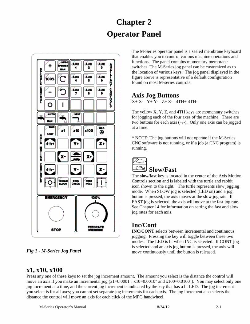
Fig 1 - M-Series Jog Panel
The M-Series operator panel is a sealed membrane keyboard that enables you to control various machine operations and functions. The panel contains momentary membrane switches. The M-Series jog panel can be customized as to the location of various keys. The jog panel displayed in the figure above is representative of a default configuration found on most M-series controls.
Axis Jog Buttons X+ X- Y+ Y- Z+ Z- 4TH+ 4TH- The yellow X, Y, Z, and 4TH keys are momentary switches for jogging each of the four axes of the machine. There are two buttons for each axis (+/-). Only one axis can be jogged at a time. * NOTE: The jog buttons will not operate if the M-Series CNC software is not running, or if a job (a CNC program) is running.
Slow/Fast
The slow/fast key is located in the center of the Axis Motion Controls section and is labeled with the turtle and rabbit icon shown to the right. The turtle represents slow jogging mode. When SLOW jog is selected (LED on) and a jog button is pressed, the axis moves at the slow jog rate. If FAST jog is selected, the axis will move at the fast jog rate. See Chapter 14 for information on setting the fast and slow jog rates for each axis.
Inc/Cont INC /CONT selects between incremental and continuous jogging. Pressing the key will toggle between these two modes. The LED is lit when INC is selected. If CONT jog is selected and an axis jog button is pressed, the axis will move continuously until the button is released.
x1, x10, x100 Press any one of these keys to set the jog increment amount. The amount you select is the distance the control will move an axis if you make an incremental jog (x1=0.0001", x10=0.0010" and x100=0.0100"). You may select only one jog increment at a time, and the current jog increment is indicated by the key that has a lit LED. The jog increment you select is for all axes; you cannot set separate jog increments for each axis. The jog increment also selects the distance the control will move an axis for each click of the MPG handwheel.
M-Series Operator’s Manual 8/24/12 2-2
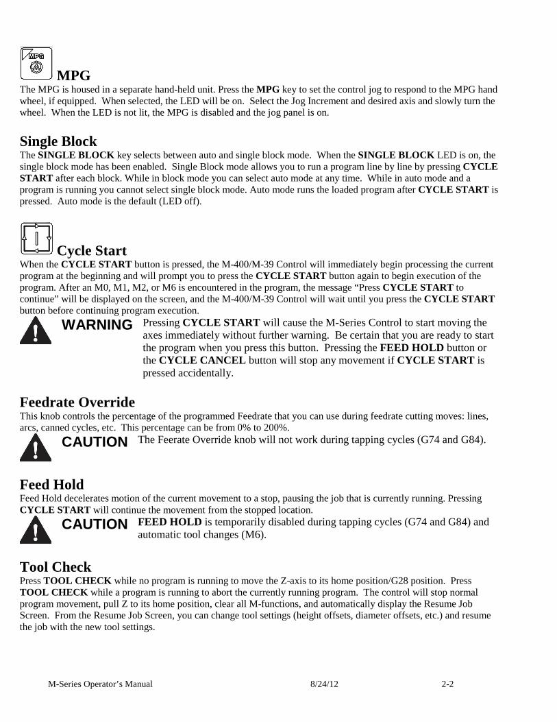
MPG The MPG is housed in a separate hand-held unit. Press the MPG key to set the control jog to respond to the MPG hand wheel, if equipped. When selected, the LED will be on. Select the Jog Increment and desired axis and slowly turn the wheel. When the LED is not lit, the MPG is disabled and the jog panel is on.
Single Block The SINGLE BLOCK key selects between auto and single block mode. When the SINGLE BLOCK LED is on, the single block mode has been enabled. Single Block mode allows you to run a program line by line by pressing CYCLE START after each block. While in block mode you can select auto mode at any time. While in auto mode and a program is running you cannot select single block mode. Auto mode runs the loaded program after CYCLE START is pressed. Auto mode is the default (LED off).
Cycle Start When the CYCLE START button is pressed, the M-400/M-39 Control will immediately begin processing the current program at the beginning and will prompt you to press the CYCLE START button again to begin execution of the program. After an M0, M1, M2, or M6 is encountered in the program, the message “Press CYCLE START to continue” will be displayed on the screen, and the M-400/M-39 Control will wait until you press the CYCLE START button before continuing program execution.
WARNING Pressing CYCLE START will cause the M-Series Control to start moving the
axes immediately without further warning. Be certain that you are ready to start the program when you press this button. Pressing the FEED HOLD button or the CYCLE CANCEL button will stop any movement if CYCLE START is pressed accidentally.
Feedrate Override This knob controls the percentage of the programmed Feedrate that you can use during feedrate cutting moves: lines, arcs, canned cycles, etc. This percentage can be from 0% to 200%.
CAUTION The Feerate Override knob will not work during tapping cycles (G74 and G84).
Feed Hold Feed Hold decelerates motion of the current movement to a stop, pausing the job that is currently running. Pressing CYCLE START will continue the movement from the stopped location.
CAUTION FEED HOLD is temporarily disabled during tapping cycles (G74 and G84) and
automatic tool changes (M6).
Tool Check Press TOOL CHECK while no program is running to move the Z-axis to its home position/G28 position. Press TOOL CHECK while a program is running to abort the currently running program. The control will stop normal program movement, pull Z to its home position, clear all M-functions, and automatically display the Resume Job Screen. From the Resume Job Screen, you can change tool settings (height offsets, diameter offsets, etc.) and resume the job with the new tool settings.
M-Series Operator’s Manual 8/24/12 2-3
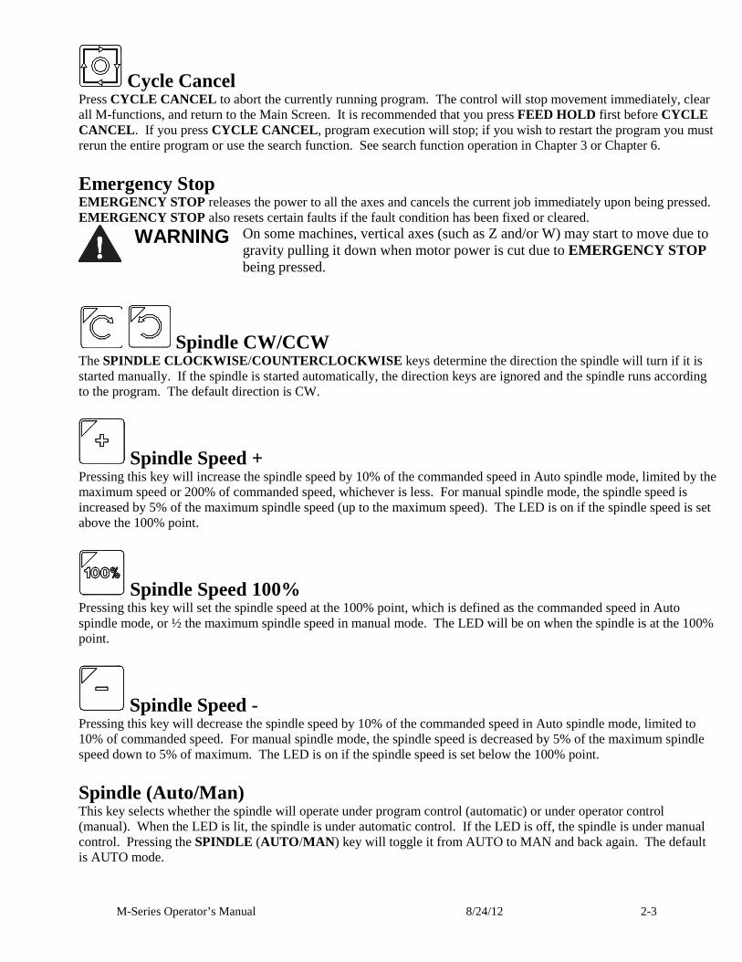
Cycle Cancel Press CYCLE CANCEL to abort the currently running program. The control will stop movement immediately, clear all M-functions, and return to the Main Screen. It is recommended that you press FEED HOLD first before CYCLE CANCEL . If you press CYCLE CANCEL , program execution will stop; if you wish to restart the program you must rerun the entire program or use the search function. See search function operation in Chapter 3 or Chapter 6.
Emergency Stop EMERGENCY STOP releases the power to all the axes and cancels the current job immediately upon being pressed. EMERGENCY STOP also resets certain faults if the fault condition has been fixed or cleared.
WARNING On some machines, vertical axes (such as Z and/or W) may start to move due to
gravity pulling it down when motor power is cut due to EMERGENCY STOP being pressed.
Spindle CW/CCW The SPINDLE CLOCKWISE /COUNTERCLOCKWISE keys determine the direction the spindle will turn if it is started manually. If the spindle is started automatically, the direction keys are ignored and the spindle runs according to the program. The default direction is CW.
Spindle Speed + Pressing this key will increase the spindle speed by 10% of the commanded speed in Auto spindle mode, limited by the maximum speed or 200% of commanded speed, whichever is less. For manual spindle mode, the spindle speed is increased by 5% of the maximum spindle speed (up to the maximum speed). The LED is on if the spindle speed is set above the 100% point.
Spindle Speed 100% Pressing this key will set the spindle speed at the 100% point, which is defined as the commanded speed in Auto spindle mode, or ½ the maximum spindle speed in manual mode. The LED will be on when the spindle is at the 100% point.
Spindle Speed - Pressing this key will decrease the spindle speed by 10% of the commanded speed in Auto spindle mode, limited to 10% of commanded speed. For manual spindle mode, the spindle speed is decreased by 5% of the maximum spindle speed down to 5% of maximum. The LED is on if the spindle speed is set below the 100% point.
Spindle (Auto/Man) This key selects whether the spindle will operate under program control (automatic) or under operator control (manual). When the LED is lit, the spindle is under automatic control. If the LED is off, the spindle is under manual control. Pressing the SPINDLE (AUTO /MAN ) key will toggle it from AUTO to MAN and back again. The default is AUTO mode.
M-Series Operator’s Manual 8/24/12 2-4
Spin Start Press the SPIN START key when manual spindle mode is selected to cause the spindle to start rotating. Press SPIN START when automatic mode is selected to restart the spindle if it has been paused with SPIN STOP.
Spin Stop Press the SPIN STOP key when manual spindle mode is selected to stop the spindle. Press SPIN STOP when automatic mode is selected to pause spindle rotation and can be restarted with SPIN START. NOTICE SPIN STOP should only be pressed during FEED HOLD or when a program is NOT
running.
Coolant Auto/Manual This key will toggle between automatic and manual control of coolant. In automatic mode, M7 (Mist) and M8 (Flood) can be used in G-code programs to select the coolant type to be enabled. In manual mode, flood coolant and mist coolant are controlled by separate keys. Note: When switching from automatic to manual mode, both flood and mist coolants are turned off automatically.
Coolant Flood In manual coolant control mode, flood coolant can be toggled off and on by pressing this key. The LED will be on when flood control is selected in either automatic or manual mode.
Coolant Mist In manual coolant control mode, mist coolant can be toggled off and on by pressing this key. The LED will be on when mist control is selected in either automatic or manual mode.
Auxiliary Function Keys (AUX1 – AUX12) The M-Series jog panel has nine auxiliary keys, some of which may be defined by customized systems.
Notes about operator panels The behavior of the control system in response to the functions listed above for the M-Series jog panel is dependent upon optional software options, the PLC program, machine parameters, and hardware wiring of the system. It is possible that the functioning explained in this chapter does not apply to a particular control system or that it may differ in some aspects.
M-Series Operator’s Manual 8/24/12 2-5
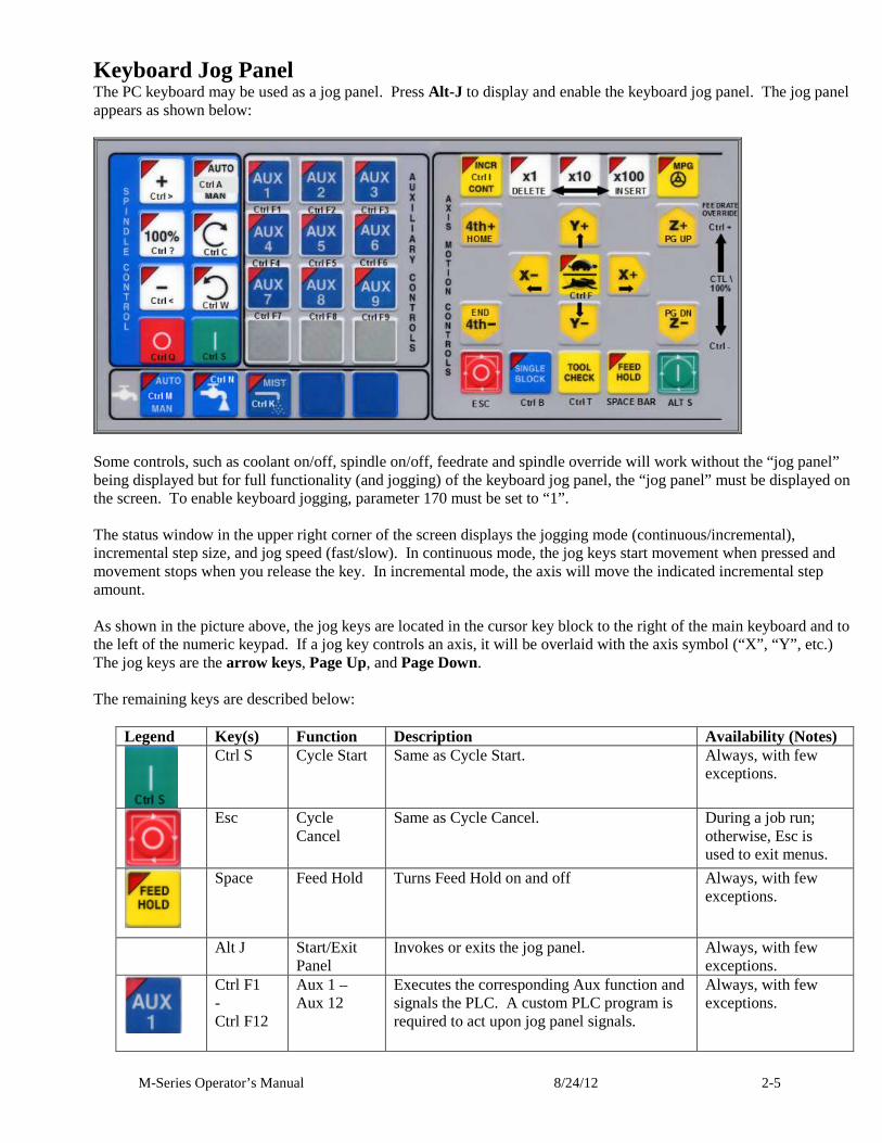
Keyboard Jog Panel The PC keyboard may be used as a jog panel. Press Alt-J to display and enable the keyboard jog panel. The jog panel appears as shown below:
Some controls, such as coolant on/off, spindle on/off, feedrate and spindle override will work without the “jog panel” being displayed but for full functionality (and jogging) of the keyboard jog panel, the “jog panel” must be displayed on the screen. To enable keyboard jogging, parameter 170 must be set to “1”. The status window in the upper right corner of the screen displays the jogging mode (continuous/incremental), incremental step size, and jog speed (fast/slow). In continuous mode, the jog keys start movement when pressed and movement stops when you release the key. In incremental mode, the axis will move the indicated incremental step amount. As shown in the picture above, the jog keys are located in the cursor key block to the right of the main keyboard and to the left of the numeric keypad. If a jog key controls an axis, it will be overlaid with the axis symbol (“X”, “Y”, etc.) The jog keys are the arrow keys, Page Up, and Page Down. The remaining keys are described below:
Legend Key(s) Function Description Availability (Notes)
Ctrl S Cycle Start Same as Cycle Start. Always, with few exceptions.
Esc Cycle Cancel
Same as Cycle Cancel. During a job run; otherwise, Esc is used to exit menus.
Space
Feed Hold Turns Feed Hold on and off Always, with few exceptions.
Alt J Start/Exit Panel
Invokes or exits the jog panel. Always, with few exceptions.
Ctrl F1 - Ctrl F12
Aux 1 – Aux 12
Executes the corresponding Aux function and signals the PLC. A custom PLC program is required to act upon jog panel signals.
Always, with few exceptions.
M-Series Operator’s Manual 8/24/12 2-6
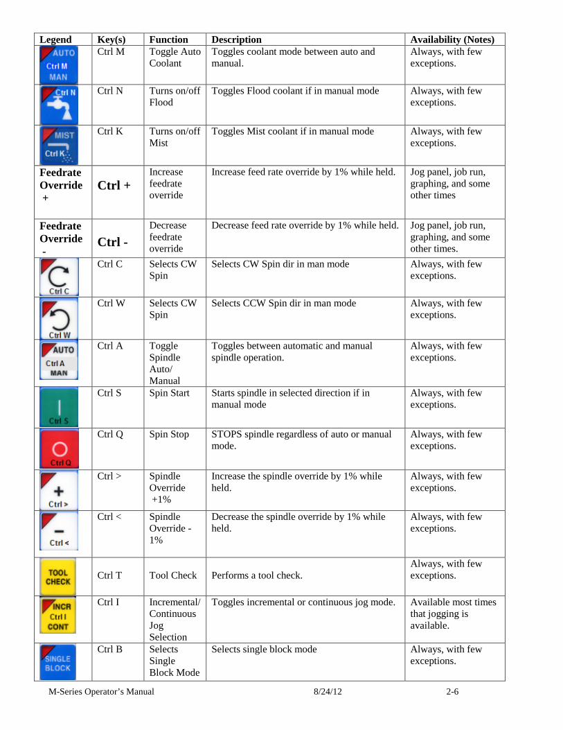
Legend Key(s) Function Description Availability (Notes)
Ctrl M Toggle Auto Coolant
Toggles coolant mode between auto and manual.
Always, with few exceptions.
Ctrl N Turns on/off Flood
Toggles Flood coolant if in manual mode Always, with few exceptions.
Ctrl K Turns on/off Mist
Toggles Mist coolant if in manual mode Always, with few exceptions.
Feedrate Override +
Ctrl + Increase feedrate override
Increase feed rate override by 1% while held. Jog panel, job run, graphing, and some other times
Feedrate Override -
Ctrl -
Decrease feedrate override
Decrease feed rate override by 1% while held. Jog panel, job run, graphing, and some other times.
Ctrl C Selects CW Spin
Selects CW Spin dir in man mode Always, with few exceptions.
Ctrl W Selects CW Spin
Selects CCW Spin dir in man mode Always, with few exceptions.
Ctrl A
Toggle Spindle Auto/ Manual
Toggles between automatic and manual spindle operation.
Always, with few exceptions.
Ctrl S Spin Start Starts spindle in selected direction if in manual mode
Always, with few exceptions.
Ctrl Q
Spin Stop STOPS spindle regardless of auto or manual mode.
Always, with few exceptions.
Ctrl > Spindle Override +1%
Increase the spindle override by 1% while held.
Always, with few exceptions.
Ctrl < Spindle Override -1%
Decrease the spindle override by 1% while held.
Always, with few exceptions.
Ctrl T
Tool Check
Performs a tool check.
Always, with few exceptions.
Ctrl I Incremental/ Continuous Jog Selection
Toggles incremental or continuous jog mode. Available most times that jogging is available.
Ctrl B Selects Single Block Mode
Selects single block mode Always, with few exceptions.
M-Series Operator’s Manual 8/24/12 2-7
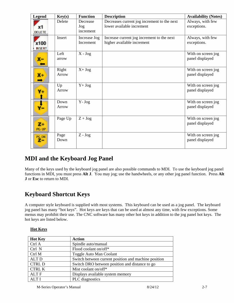
Legend Key(s) Function Description Availability (Notes)
Delete Decrease Jog increment
Decreases current jog increment to the next lower available increment
Always, with few exceptions.
Insert Increase Jog Increment
Increase current jog increment to the next higher available increment
Always, with few exceptions.
Left arrow
X - Jog With on screen jog panel displayed
Right Arrow
X+ Jog With on screen jog panel displayed
Up Arrow
Y+ Jog With on screen jog panel displayed
Down Arrow
Y- Jog With on screen jog panel displayed
Page Up Z + Jog With on screen jog panel displayed
Page Down
Z - Jog With on screen jog panel displayed
MDI and the Keyboard Jog Panel Many of the keys used by the keyboard jog panel are also possible commands to MDI. To use the keyboard jog panel functions in MDI, you must press Alt J . You may jog; use the handwheels, or any other jog panel function. Press Alt J or Esc to return to MDI.
Keyboard Shortcut Keys A computer style keyboard is supplied with most systems. This keyboard can be used as a jog panel. The keyboard jog panel has many “hot keys”. Hot keys are keys that can be used at almost any time, with few exceptions. Some menus may prohibit their use. The CNC software has many other hot keys in addition to the jog panel hot keys. The hot keys are listed below.
Hot Keys
Hot Key Action Ctrl A Spindle auto/manual Ctrl N Flood coolant on/off* Ctrl M Toggle Auto Man Coolant ALT D Switch between current position and machine position CTRL D Switch DRO between position and distance to go CTRL K Mist coolant on/off* ALT F Displays available system memory ALT I PLC diagnostics
M-Series Operator’s Manual 8/24/12 2-8
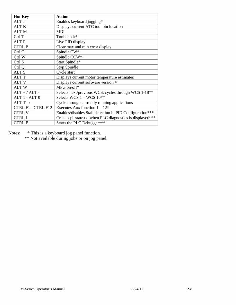
Hot Key Action ALT J Enables keyboard jogging* ALT K Displays current ATC tool bin location ALT M MDI Ctrl T Tool check* ALT P Live PID display CTRL P Clear max and min error display Ctrl C Spindle CW* Ctrl W Spindle CCW* Ctrl S Start Spindle* Ctrl Q Stop Spindle ALT S Cycle start ALT T Displays current motor temperature estimates ALT V Displays current software version # ALT W MPG on/off* ALT + / ALT - Selects next/previous WCS, cycles through WCS 1-18** ALT 1 - ALT 0 Selects WCS 1 – WCS 10** ALT Tab Cycle through currently running applications CTRL F1 - CTRL F12 Executes Aux function 1 – 12* CTRL V Enables/disables Stall detection in PID Configuration*** CTRL I Creates plcstate.txt when PLC diagnostics is displayed*** CTRL E Starts the PLC Debugger***
Notes: * This is a keyboard jog panel function.
** Not available during jobs or on jog panel.
M-Series Operator’s Manual 8/24/12 3-1
Chapter 3 CNC Software Main Screen
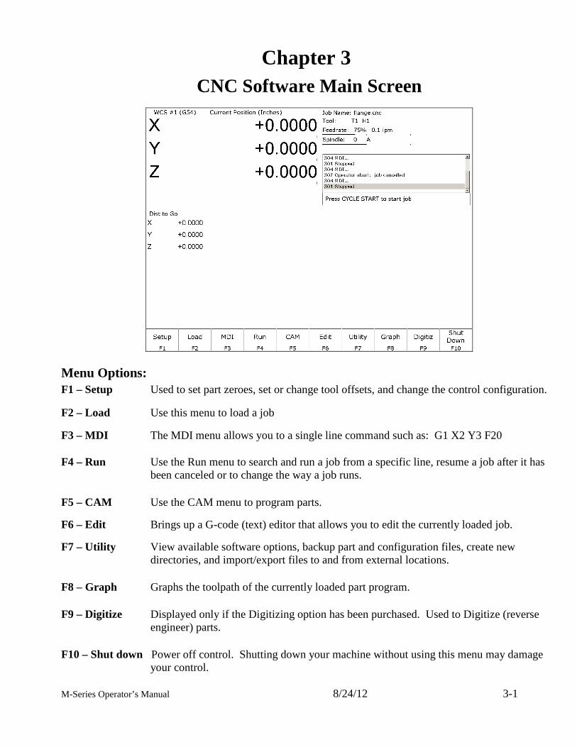
Menu Options: F1 – Setup Used to set part zeroes, set or change tool offsets, and change the control configuration. F2 – Load Use this menu to load a job F3 – MDI The MDI menu allows you to a single line command such as: G1 X2 Y3 F20 F4 – Run Use the Run menu to search and run a job from a specific line, resume a job after it has
been canceled or to change the way a job runs. F5 – CAM Use the CAM menu to program parts.
F6 – Edit Brings up a G-code (text) editor that allows you to edit the currently loaded job.
F7 – Utility View available software options, backup part and configuration files, create new directories, and import/export files to and from external locations.
F8 – Graph Graphs the toolpath of the currently loaded part program. F9 – Digitize Displayed only if the Digitizing option has been purchased. Used to Digitize (reverse
engineer) parts. F10 – Shut down Power off control. Shutting down your machine without using this menu may damage
your control.
M-Series Operator’s Manual 8/24/12 3-2
F1- Setup Menu
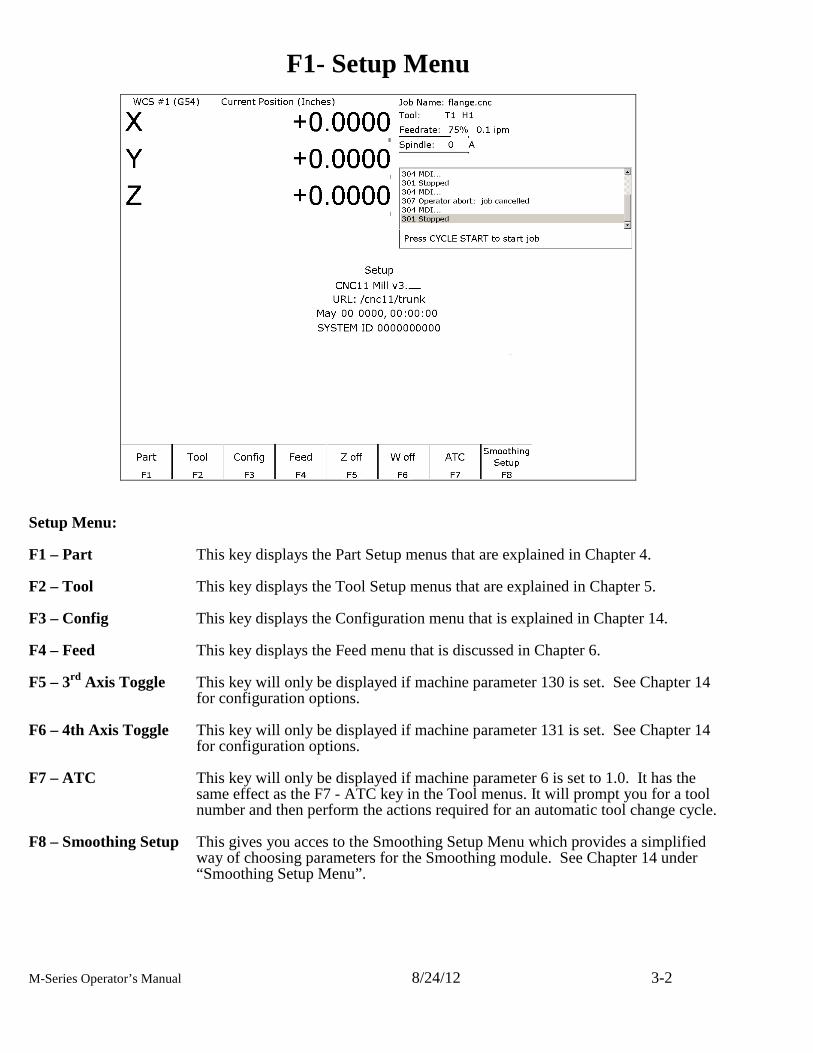
Setup Menu: F1 – Part This key displays the Part Setup menus that are explained in Chapter 4. F2 – Tool This key displays the Tool Setup menus that are explained in Chapter 5. F3 – Config This key displays the Configuration menu that is explained in Chapter 14. F4 – Feed This key displays the Feed menu that is discussed in Chapter 6. F5 – 3rd Axis Toggle This key will only be displayed if machine parameter 130 is set. See Chapter 14
for configuration options. F6 – 4th Axis Toggle This key will only be displayed if machine parameter 131 is set. See Chapter 14
for configuration options. F7 – ATC This key will only be displayed if machine parameter 6 is set to 1.0. It has the
same effect as the F7 - ATC key in the Tool menus. It will prompt you for a tool number and then perform the actions required for an automatic tool change cycle.
F8 – Smoothing Setup This gives you acces to the Smoothing Setup Menu which provides a simplified
way of choosing parameters for the Smoothing module. See Chapter 14 under “Smoothing Setup Menu”.
M-Series Operator’s Manual 8/24/12 3-3
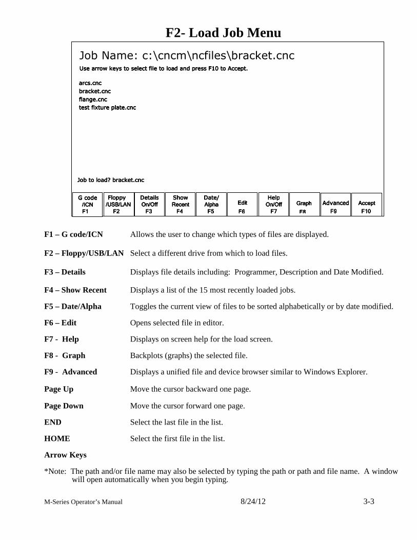
F2- Load Job Menu F1 – G code/ICN Allows the user to change which types of files are displayed. F2 – Floppy/USB/LAN Select a different drive from which to load files. F3 – Details Displays file details including: Programmer, Description and Date Modified. F4 – Show Recent Displays a list of the 15 most recently loaded jobs. F5 – Date/Alpha Toggles the current view of files to be sorted alphabetically or by date modified. F6 – Edit Opens selected file in editor. F7 - Help Displays on screen help for the load screen. F8 - Graph Backplots (graphs) the selected file. F9 - Advanced Displays a unified file and device browser similar to Windows Explorer. Page Up Move the cursor backward one page. Page Down Move the cursor forward one page. END Select the last file in the list. HOME Select the first file in the list. Arrow Keys *Note: The path and/or file name may also be selected by typing the path or path and file name. A window
will open automatically when you begin typing.
Floppy Floppy Floppy Floppy
////USB/LANUSB/LANUSB/LANUSB/LAN
FFFF2222
DetailsDetailsDetailsDetails
On/OffOn/OffOn/OffOn/Off
FFFF3333
ShowShowShowShow
RecentRecentRecentRecent
FFFF4444
Date/Date/Date/Date/
AlphaAlphaAlphaAlpha
FFFF5555
EditEditEditEdit
FFFF6666
HelpHelpHelpHelp
OnOnOnOn////OffOffOffOff
FFFF7777
Graph Graph Graph Graph
FFFF8888
AdvancedAdvancedAdvancedAdvanced
FFFF9999
AcceptAcceptAcceptAccept
F1F1F1F10000
G code G code G code G code
/ICN/ICN/ICN/ICN
F1F1F1F1
Job Name: c:\cncm\ncfiles\bracket.cnc Use arrow keys to select file to load and press F10 to Accept.Use arrow keys to select file to load and press F10 to Accept.Use arrow keys to select file to load and press F10 to Accept.Use arrow keys to select file to load and press F10 to Accept.
arcs.cncarcs.cncarcs.cncarcs.cnc
bracket.cncbracket.cncbracket.cncbracket.cnc
flange.cncflange.cncflange.cncflange.cnc
test fixture plate.cnctest fixture plate.cnctest fixture plate.cnctest fixture plate.cnc
Job Job Job Job totototo load? bracket.cnc load? bracket.cnc load? bracket.cnc load? bracket.cnc
M-Series Operator’s Manual 8/24/12 3-4
F3 –MDI
MDI mode allows you to directly enter M and G-codes one line at time. After entering the M and G-codes you wish to run, press cycle start to have the controller execute the command. When the command has finished executing the command, it will prompt you for another line. When you are finished entering commands, press ESC. Examples: Block? G92X0Y0 ; Set the current XY position to 0,0 Block? M92 /Z ; Move the Z to the positive limit. Block? M26 /Z ; Set the current Z position as Z home
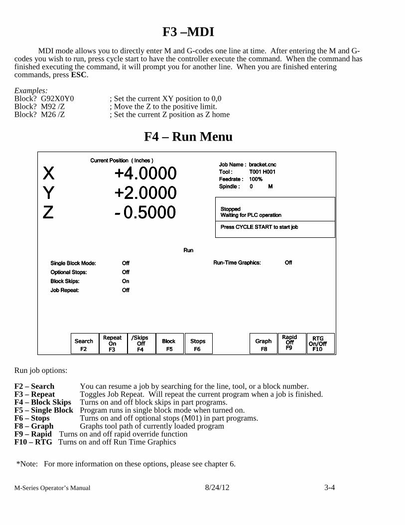
F4 – Run Menu Run job options: F2 – Search You can resume a job by searching for the line, tool, or a block number. F3 – Repeat Toggles Job Repeat. Will repeat the current program when a job is finished. F4 – Block Skips Turns on and off block skips in part programs. F5 – Single Block Program runs in single block mode when turned on. F6 – Stops Turns on and off optional stops (M01) in part programs. F8 – Graph Graphs tool path of currently loaded program F9 – Rapid Turns on and off rapid override function F10 – RTG Turns on and off Run Time Graphics *Note: For more information on these options, please see chapter 6.
Current Position (Current Position (Current Position (Current Position ( InchesInchesInchesInches ) ) ) )
X +4.0000X +4.0000X +4.0000X +4.0000 Y +2.0000Y +2.0000Y +2.0000Y +2.0000 ZZZZ ---- 0.50000.50000.50000.5000
Job Name : Job Name : Job Name : Job Name : bbbbracket.cncracket.cncracket.cncracket.cnc
Tool : Tool : Tool : Tool : T001 H001T001 H001T001 H001T001 H001
Feedrate : 100%Feedrate : 100%Feedrate : 100%Feedrate : 100%
Spindle : 0 Spindle : 0 Spindle : 0 Spindle : 0 M M M M
StoppedStoppedStoppedStopped Waiting for PLC operationWaiting for PLC operationWaiting for PLC operationWaiting for PLC operation StoppedStoppedStoppedStopped PresPresPresPress CYCLE START to start jobs CYCLE START to start jobs CYCLE START to start jobs CYCLE START to start job
Repeat Repeat Repeat Repeat On On On On F3F3F3F3
/Skips /Skips /Skips /Skips Off Off Off Off F F F F4444
RTG RTG RTG RTG On/OffOn/OffOn/OffOn/Off F10F10F10F10
Rapid Rapid Rapid Rapid Off Off Off Off F9 F9 F9 F9
BlockBlockBlockBlock
F5F5F5F5 GraphGraphGraphGraph
F8F8F8F8
Stops Stops Stops Stops
F6F6F6F6
Searc Searc Searc Searchhhh
F2F2F2F2
Single Block Mode:Single Block Mode:Single Block Mode:Single Block Mode: OffOffOffOff
Optional Stops:Optional Stops:Optional Stops:Optional Stops: OffOffOffOff
Block Skips:Block Skips:Block Skips:Block Skips: OnOnOnOn
Job Repeat:Job Repeat:Job Repeat:Job Repeat: OffOffOffOff
RunRunRunRun
RunRunRunRun----Time Graphics:Time Graphics:Time Graphics:Time Graphics: OffOffOffOff
M-Series Operator’s Manual 8/24/12 3-5
F5 – CAM
Choose F5-CAM to program parts. The default part programming system is Intercon. Intercon is a
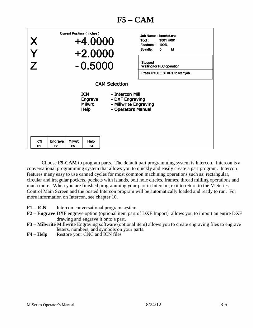
conversational programming system that allows you to quickly and easily create a part program. Intercon features many easy to use canned cycles for most common machining operations such as: rectangular, circular and irregular pockets, pockets with islands, bolt hole circles, frames, thread milling operations and much more. When you are finished programming your part in Intercon, exit to return to the M-Series Control Main Screen and the posted Intercon program will be automatically loaded and ready to run. For more information on Intercon, see chapter 10. F1 – ICN Intercon conversational program system F2 – Engrave DXF engrave option (optional item part of DXF Import) allows you to import an entire DXF
drawing and engrave it onto a part. F3 – Milwrite Millwrite Engraving software (optional item) allows you to create engraving files to engrave
letters, numbers, and symbols on your parts. F4 – Help Restore your CNC and ICN files
ICNICNICNICN ---- Intercon Mill Intercon Mill Intercon Mill Intercon Mill
EngraveEngraveEngraveEngrave ---- DXF Engraving DXF Engraving DXF Engraving DXF Engraving
MilwrtMilwrtMilwrtMilwrt ---- Mill Mill Mill Millwrite Engravingwrite Engravingwrite Engravingwrite Engraving
HelpHelpHelpHelp ---- Operators Manual Operators Manual Operators Manual Operators Manual
CAM SelectionCAM SelectionCAM SelectionCAM Selection
Current Position (Current Position (Current Position (Current Position ( InchesInchesInchesInches ) ) ) )
X X X X +4.0000 +4.0000 +4.0000 +4.0000 Y +2.0000Y +2.0000Y +2.0000Y +2.0000 ZZZZ ---- 0.50000.50000.50000.5000
Job Job Job Job Name : : : : bbbbracket.cncracket.cncracket.cncracket.cnc
Tool : Tool : Tool : Tool : T001 H001T001 H001T001 H001T001 H001
Feedrate : 100%Feedrate : 100%Feedrate : 100%Feedrate : 100%
Spindle : 0 M Spindle : 0 M Spindle : 0 M Spindle : 0 M
StoppedStoppedStoppedStopped Waiting for PLC operationWaiting for PLC operationWaiting for PLC operationWaiting for PLC operation
PresPresPresPress CYCLE START to start jobs CYCLE START to start jobs CYCLE START to start jobs CYCLE START to start job
ICNICNICNICN
FFFF1111 HelpHelpHelpHelp
F4F4F4F4
MilwrtMilwrtMilwrtMilwrt
F6F6F6F6
EngraveEngraveEngraveEngrave
F2F2F2F2
CAMCAMCAMCAM Selection Selection Selection Selection
ICNICNICNICN ---- Intercon Mill Intercon Mill Intercon Mill Intercon Mill
EngraveEngraveEngraveEngrave ---- DXF Engraving DXF Engraving DXF Engraving DXF Engraving
Milwrt Milwrt Milwrt Milwrt ---- Millwrite Engraving Millwrite Engraving Millwrite Engraving Millwrite Engraving
HelpHelpHelpHelp ---- Operators Manual Operators Manual Operators Manual Operators Manual
M-Series Operator’s Manual 8/24/12 3-6
F6 – Edit This key causes the control to load the current job into a text editor for viewing and/or editing. When editing, care must be taken to save the file and to quit and exit the text editor before running the file (the current job). Modifying a file that is currently running as the current job is dangerous and will cause unexpected results. It is best practice to not edit any files while the machine is moving.
WARNING Editing a file (modifying and saving) while the machine is moving can cause
personal injury or machine damage. Also, note that the C:\CNCM directory contains configuration files and binary data. DO NOT edit these files. Doing so can cause loss of data and serious malfunctions.
WARNING Do not edit configuration data located in the C:\CNCM directory. Doing so can
cause personal injury or machine damage.
F7 – Utility
From the utility menu you can view available software options, perform diagnostics, backup part and configuration files, create new directories and import or export files to and from external locations. For further information please see chapter 7. F2 – Restore Report Update your control’s configuration with a report.zip file. F3 – Backup Files Backup your CNC and ICN files F4 – Restore Files Restore your CNC and ICN files F5 – File Ops Use this menu to perform file and directory operations. F6 – User Maint Perform user maintenance. F7 – Create Report Generates a backup of system configuration files called report.zip. F8 – Options Shows the software options that you have purchased or added to your control. F9 – Logs Shows the messages and errors that have been logged by the control.
M-Series Operator’s Manual 8/24/12 3-7
F8 – Graph
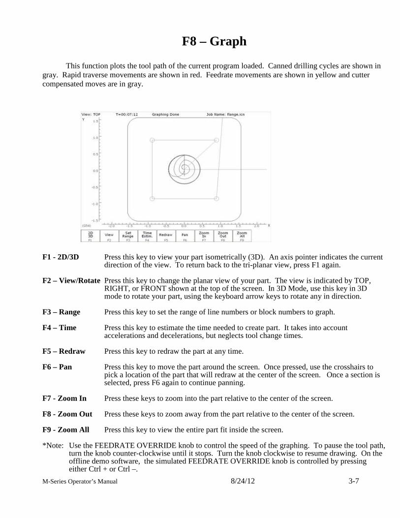
This function plots the tool path of the current program loaded. Canned drilling cycles are shown in gray. Rapid traverse movements are shown in red. Feedrate movements are shown in yellow and cutter compensated moves are in gray. F1 - 2D/3D Press this key to view your part isometrically (3D). An axis pointer indicates the current
direction of the view. To return back to the tri-planar view, press F1 again. F2 – View/Rotate Press this key to change the planar view of your part. The view is indicated by TOP,
RIGHT, or FRONT shown at the top of the screen. In 3D Mode, use this key in 3D mode to rotate your part, using the keyboard arrow keys to rotate any in direction.
F3 – Range Press this key to set the range of line numbers or block numbers to graph. F4 – Time Press this key to estimate the time needed to create part. It takes into account
accelerations and decelerations, but neglects tool change times. F5 – Redraw Press this key to redraw the part at any time. F6 – Pan Press this key to move the part around the screen. Once pressed, use the crosshairs to
pick a location of the part that will redraw at the center of the screen. Once a section is selected, press F6 again to continue panning.
F7 - Zoom In Press these keys to zoom into the part relative to the center of the screen. F8 - Zoom Out Press these keys to zoom away from the part relative to the center of the screen. F9 - Zoom All Press this key to view the entire part fit inside the screen. *Note: Use the FEEDRATE OVERRIDE knob to control the speed of the graphing. To pause the tool path,
turn the knob counter-clockwise until it stops. Turn the knob clockwise to resume drawing. On the offline demo software, the simulated FEEDRATE OVERRIDE knob is controlled by pressing either Ctrl + or Ctrl –.
M-Series Operator’s Manual 8/24/12 3-8
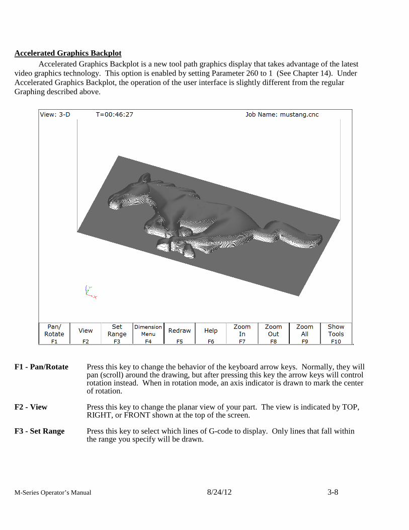
Accelerated Graphics Backplot
Accelerated Graphics Backplot is a new tool path graphics display that takes advantage of the latest video graphics technology. This option is enabled by setting Parameter 260 to 1 (See Chapter 14). Under Accelerated Graphics Backplot, the operation of the user interface is slightly different from the regular Graphing described above.
. F1 - Pan/Rotate Press this key to change the behavior of the keyboard arrow keys. Normally, they will
pan (scroll) around the drawing, but after pressing this key the arrow keys will control rotation instead. When in rotation mode, an axis indicator is drawn to mark the center of rotation.
F2 - View Press this key to change the planar view of your part. The view is indicated by TOP,
RIGHT, or FRONT shown at the top of the screen. F3 - Set Range Press this key to select which lines of G-code to display. Only lines that fall within
the range you specify will be drawn.
M-Series Operator’s Manual 8/24/12 3-9
F4 - Dimension Menu Press this key to access the following sub-menu of options: F1 – Prev Line: Press this to walk forward to the next G-code line and graphically highlight it. If this G-code line contains movement, the Start and End points will be displayed at the bottom of the screen. F2 – Next Line: Press this to walk backward to the previous G-code line and graphically highlight it. If this G-code line contains movement, the Start and End points will be displayed at the bottom of the screen. F3 – Go To Line: Press this key to graphically highlight a particular G-code line whose line number you specify. If this G-code line contains movement, the Start and End points will be displayed. F4 – Measure: Use this feature to measure between any 2 selected points. To do this, use a mouse to move the pointer over the first point and then press F4 – Measure to anchor the first point. Then use the mouse to move the pointer to the second point. As you move the mouse towards the second point, you will notice an Offset and Measurement display changing dynamically as you move the mouse. Also you may notice some “snap to” effects as you move the pointer close to start and end points of entities that make up your program.
F5 - Redraw Press this key to redraw the part slowly, which can be useful for visualizing the movements the machine will make. While the display is being redrawn, you can use the feedrate override knob to adjust the rate at which it is being drawn. If you don't have a feedrate override knob, the + and - keys can be used to adjust the rate. Pressing F5 again will cancel this mode.
F6 - Hide Rapids Press this key to hide rapid movements. Press it again to show them. F7 - Zoom In Press these keys to zoom into the part relative to the center of the screen. F8 - Zoom Out Press these keys to zoom away from the part relative to the center of the screen. F9 - Zoom All Press this key to fit the entire part inside the screen. F10 - Show Tools Press this key to show the tools menu, which allows you to highlight movements of
certain tools. Press this key again to hide the tools menu. Spacebar - Measure Press this key to take a measurement between two points. In a 2D view, this
measurement will be a 2D measurement. In a 3D view, it will be a 3D measurement (and the measurement will only be valid if the crosshairs are snapped to a line of the tool path).
*Note: If you have a mouse or touch screen attached to your device, you can use that to control the graphing window. Holding the left mouse button allows you to drag the part across the screen, while the right mouse button controls rotation of the part. Spinning the mouse wheel (or holding both left and right buttons) zooms in and out. Double clicking on a feedrate movement will center the camera on that movement (which is very useful) and also tells you the length of that movement. For touchscreen operation, use the F1 key to switch between Pan and Rotate modes.
M-Series Operator’s Manual 8/24/12 3-10
F9 – Digitize
Use this to bring up the Digitize screen. This screen allows you to set up and run touch probe digitizing. See Chapter 8 for a detailed description of the digitizing operation.
F10 – Shutdown
Use to enter the Shutdown menu. This menu allows you to park the machine, power off the control, start a command window or exit CNC software. F1 – Park Use this to park the machine at the end of the day for quicker machine homing at
startup. Once F10- Park is selected, The CYCLE START key must be press to start machine movement. The park feature homes each axis, at the maximum rate, to ¼ of a motor revolution from its home position.
F2 – Poweroff Use this to properly shutdown the control. With most controls, this action turns off
the control once the system has prepared itself to be shutdown. Just like a desktop computer, the control should be properly shutdown before turning off the power in order to reduce the risk of corrupting data on the hard drive. This will only turn off the control. The machine itself will still need to be manually turned off.
F6 – System Prompt This brings up the command line interface. Type the command exit to exit the
command window. F9 – Exit CNC11 Use this to exit the CNC control software.
M-Series Operator’s Manual 8/24/12 4-1
Chapter 4 Part Setup
(F1 from Setup)
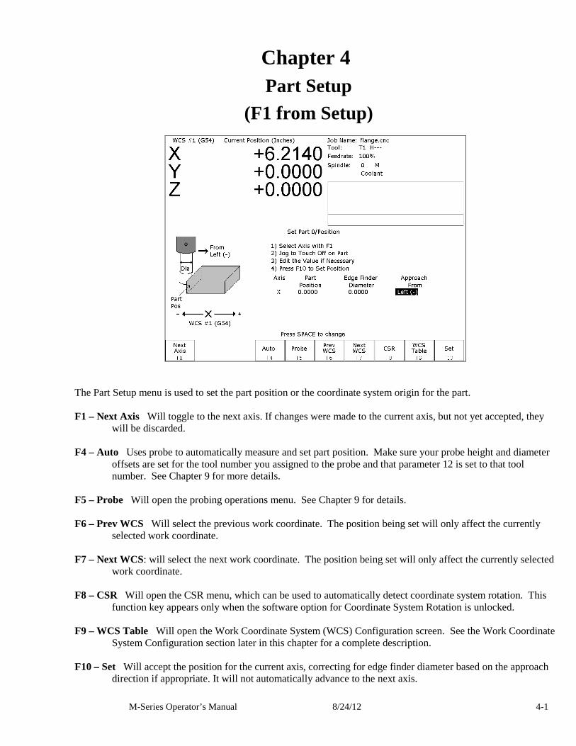
The Part Setup menu is used to set the part position or the coordinate system origin for the part. F1 – Next Axis Will toggle to the next axis. If changes were made to the current axis, but not yet accepted, they
will be discarded. F4 – Auto Uses probe to automatically measure and set part position. Make sure your probe height and diameter
offsets are set for the tool number you assigned to the probe and that parameter 12 is set to that tool number. See Chapter 9 for more details.
F5 – Probe Will open the probing operations menu. See Chapter 9 for details. F6 – Prev WCS Will select the previous work coordinate. The position being set will only affect the currently
selected work coordinate. F7 – Next WCS: will select the next work coordinate. The position being set will only affect the currently selected
work coordinate. F8 – CSR Will open the CSR menu, which can be used to automatically detect coordinate system rotation. This
function key appears only when the software option for Coordinate System Rotation is unlocked. F9 – WCS Table Will open the Work Coordinate System (WCS) Configuration screen. See the Work Coordinate
System Configuration section later in this chapter for a complete description. F10 – Set Will accept the position for the current axis, correcting for edge finder diameter based on the approach
direction if appropriate. It will not automatically advance to the next axis.
M-Series Operator’s Manual 8/24/12 4-2
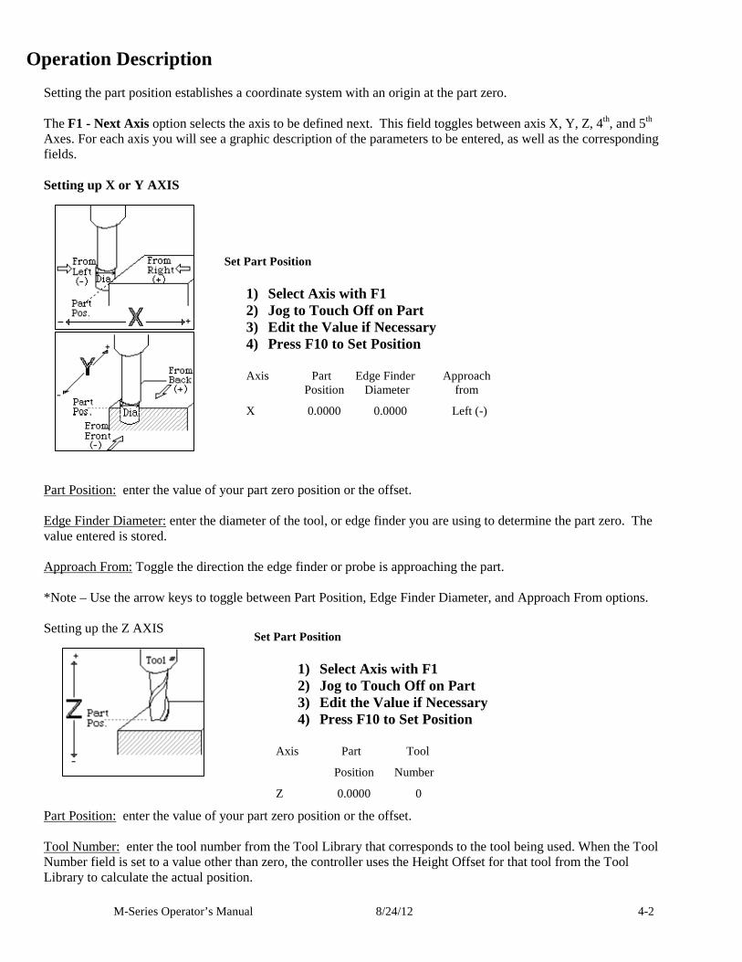
Operation Description Setting the part position establishes a coordinate system with an origin at the part zero. The F1 - Next Axis option selects the axis to be defined next. This field toggles between axis X, Y, Z, 4th, and 5th Axes. For each axis you will see a graphic description of the parameters to be entered, as well as the corresponding fields. Setting up X or Y AXIS
Part Position: enter the value of your part zero position or the offset. Edge Finder Diameter: enter the diameter of the tool, or edge finder you are using to determine the part zero. The value entered is stored. Approach From: Toggle the direction the edge finder or probe is approaching the part. *Note – Use the arrow keys to toggle between Part Position, Edge Finder Diameter, and Approach From options. Setting up the Z AXIS
Part Position: enter the value of your part zero position or the offset. Tool Number: enter the tool number from the Tool Library that corresponds to the tool being used. When the Tool Number field is set to a value other than zero, the controller uses the Height Offset for that tool from the Tool Library to calculate the actual position.
Set Part Position
1) Select Axis with F1 2) Jog to Touch Off on Part 3) Edit the Value if Necessary 4) Press F10 to Set Position Axis Part Edge Finder Approach Position Diameter from
X 0.0000 0.0000 Left (-)
Set Part Position
1) Select Axis with F1 2) Jog to Touch Off on Part 3) Edit the Value if Necessary 4) Press F10 to Set Position
Axis Part Tool
Position Number
Z 0.0000 0
M-Series Operator’s Manual 8/24/12 4-3
Example 1 (You are using the reference tool to find the Z-axis part zero): Set Tool Number to 0: setting the Tool Number to zero tells the controller that you are using the reference tool. Example 2 (You are using a tool other than the reference tool, and not a ball nose cutter): Set Tool Number to a number tool that is assigned in the tool library (make sure its height offset is set). Example 3 (You are using a ball nose cutter, other than the reference tool): Set Part Position to the position of the surface plus the nose radius of the ball nose cutter, set Tool Number to the number this tool is assigned in the tool library. The Tool and Offset libraries must be up to date before setting the Z-axis Part Zero. Setting up the 4th or 5th AXIS***
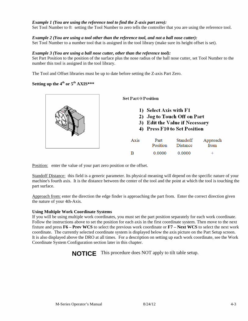
Position: enter the value of your part zero position or the offset. Standoff Distance: this field is a generic parameter. Its physical meaning will depend on the specific nature of your machine's fourth axis. It is the distance between the center of the tool and the point at which the tool is touching the part surface. Approach from: enter the direction the edge finder is approaching the part from. Enter the correct direction given the nature of your 4th-Axis. Using Multiple Work Coordinate Systems If you will be using multiple work coordinates, you must set the part position separately for each work coordinate. Follow the instructions above to set the position for each axis in the first coordinate system. Then move to the next fixture and press F6 – Prev WCS to select the previous work coordinate or F7 – Next WCS to select the next work coordinate. The currently selected coordinate system is displayed below the axis picture on the Part Setup screen. It is also displayed above the DRO at all times. For a description on setting up each work coordinate, see the Work Coordinate System Configuration section later in this chapter.
NOTICE This procedure does NOT apply to tilt table setup.
M-Series Operator’s Manual 8/24/12 4-4
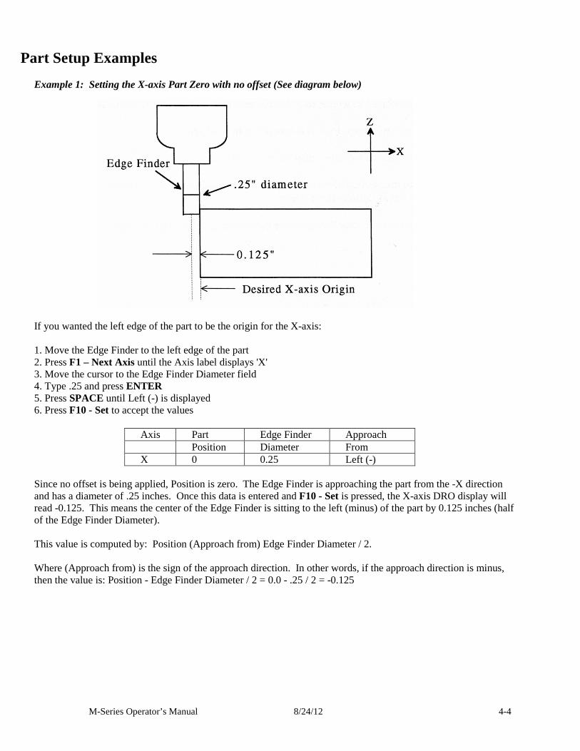
Part Setup Examples Example 1: Setting the X-axis Part Zero with no offset (See diagram below)
If you wanted the left edge of the part to be the origin for the X-axis: 1. Move the Edge Finder to the left edge of the part 2. Press F1 – Next Axis until the Axis label displays 'X' 3. Move the cursor to the Edge Finder Diameter field 4. Type .25 and press ENTER 5. Press SPACE until Left (-) is displayed 6. Press F10 - Set to accept the values
Axis Part Edge Finder Approach Position Diameter From X 0 0.25 Left (-)
Since no offset is being applied, Position is zero. The Edge Finder is approaching the part from the -X direction and has a diameter of .25 inches. Once this data is entered and F10 - Set is pressed, the X-axis DRO display will read -0.125. This means the center of the Edge Finder is sitting to the left (minus) of the part by 0.125 inches (half of the Edge Finder Diameter). This value is computed by: Position (Approach from) Edge Finder Diameter / 2. Where (Approach from) is the sign of the approach direction. In other words, if the approach direction is minus, then the value is: Position - Edge Finder Diameter / 2 = 0.0 - .25 / 2 = -0.125
M-Series Operator’s Manual 8/24/12 4-5
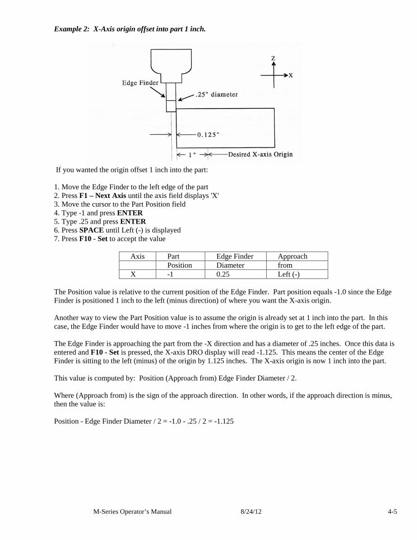
Example 2: X-Axis origin offset into part 1 inch.
If you wanted the origin offset 1 inch into the part: 1. Move the Edge Finder to the left edge of the part 2. Press F1 – Next Axis until the axis field displays 'X' 3. Move the cursor to the Part Position field 4. Type -1 and press ENTER 5. Type .25 and press ENTER 6. Press SPACE until Left (-) is displayed 7. Press F10 - Set to accept the value
Axis Part Edge Finder Approach Position Diameter from X -1 0.25 Left (-)
The Position value is relative to the current position of the Edge Finder. Part position equals -1.0 since the Edge Finder is positioned 1 inch to the left (minus direction) of where you want the X-axis origin. Another way to view the Part Position value is to assume the origin is already set at 1 inch into the part. In this case, the Edge Finder would have to move -1 inches from where the origin is to get to the left edge of the part. The Edge Finder is approaching the part from the -X direction and has a diameter of .25 inches. Once this data is entered and F10 - Set is pressed, the X-axis DRO display will read -1.125. This means the center of the Edge Finder is sitting to the left (minus) of the origin by 1.125 inches. The X-axis origin is now 1 inch into the part. This value is computed by: Position (Approach from) Edge Finder Diameter / 2. Where (Approach from) is the sign of the approach direction. In other words, if the approach direction is minus, then the value is: Position - Edge Finder Diameter / 2 = -1.0 - .25 / 2 = -1.125
M-Series Operator’s Manual 8/24/12 4-6
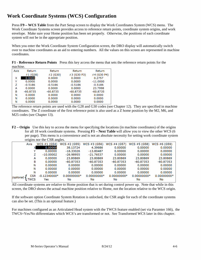
Work Coordinate Systems (WCS) Configuration Press F9 – WCS Table from the Part Setup screen to display the Work Coordinates System (WCS) menu. The Work Coordinate Systems screen provides access to reference return points, coordinate system origins, and work envelope. Make sure your Home position has been set properly. Otherwise, the positions of each coordinate system will not be in the appropriate position. When you enter the Work Coordinate System Configuration screen, the DRO display will automatically switch over to machine coordinates as an aid to entering numbers. All the values on this screen are represented in machine coordinates. F1 - Reference Return Points Press this key access the menu that sets the reference return points for the machine.
The reference return points are used with the G28 and G30 codes (see Chapter 12). They are specified in machine coordinates. The Z coordinate of the first reference point is also used as a Z home position by the M2, M6, and M25 codes (see Chapter 13). F2 – Origin Use this key to access the menu for specifying the locations (in machine coordinates) of the origins
for all 18 work coordinate systems. Pressing F1 – Next Table will allow you to view the other WCS (6 per page). This menu is a convenience and is not an absolute necessity for setting work coordinate system origins nor the CSR angles.
All coordinate systems are relative to Home position that is set during control power up. Note that while in this screen, the DRO shows the actual machine position relative to Home, not the location relative to the WCS origin. If the software option Coordinate System Rotation is unlocked, the CSR angle for each of the coordinate systems can also be set. (This is an optional feature.) For machines configured as an Articulated Head system with the TWCS feature enabled (set via Paramter 166), the TWCS=Yes/No differentiates which WCS’s are transformed or not. See Transformed WCS later in this chapter.
M-Series Operator’s Manual 8/24/12 4-7
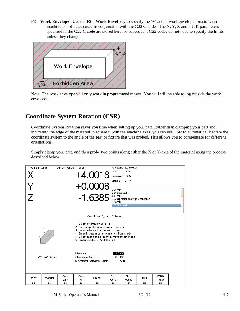
F3 – Work Envelope Use the F3 – Work Envel key to specify the ‘+’ and ‘-‘work envelope locations (in
machine coordinates) used in conjunction with the G22 G code. The X, Y, Z and I, J, K parameters specified in the G22 G code are stored here, so subsequent G22 codes do not need to specify the limits unless they change.
Note: The work envelope will only work in programmed moves. You will still be able to jog outside the work envelope.
Coordinate System Rotation (CSR) Coordinate System Rotation saves you time when setting up your part. Rather than clamping your part and indicating the edge of the material to square it with the machine axes, you can use CSR to automatically rotate the coordinate system to the angle of the part or fixture that was probed. This allows you to compensate for different orientations. Simply clamp your part, and then probe two points along either the X or Y-axis of the material using the process described below.
M-Series Operator’s Manual 8/24/12 4-8
F1 - Orient is used to select the orientation for the CSR measurement. There are four possible orientations, which
are: from the front (pictured above), the back, and the left and right sides. F2 - Manual is used to determine the CSR angle without probing. The user jogs an edge finder to two positions
along one wall. These positions will be used for computing the CSR angle. F3 - Zero Cur is used to set the CSR angle for the current WCS to zero. F4 - Zero All is used to set all CSR angles to zero. F5 – Probe Will open the probing operations menu. See Chapter 9 for details. F6 - Prev WCS and F7 - Next WCS are used to cycle through the available WCS systems. F8 – MDI The MDI menu allows you to a single line command such as: G1 X2 Y3 F20 F9 - WCS Table is a shortcut to the Work Coordinate System Configuration Screen described above. The instructions on how to perform a CSR measurement are numbered on the screen. Distance: The distance the X-axis (in front or back orientation) or Y-axis (in right or left side orientation) will move to probe the second point. If the distance is negative, the axis will be moved in the negative direction. Clearance Amount: The distance the Z-axis will be moved upward when moving between the first probe point and the second probe point. The clearance move will only be made when using the “Auto” option of the Movement between Points. Movement between Points can be toggled between Jog and Auto modes. In Auto mode, the clearing moves are made automatically as well as the move to the second point. In Jog mode, a prompt will be displayed in the center of the screen after the first point is probed.
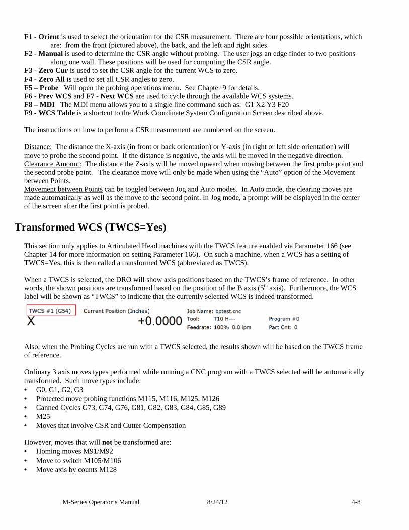
Transformed WCS (TWCS=Yes) This section only applies to Articulated Head machines with the TWCS feature enabled via Parameter 166 (see Chapter 14 for more information on setting Parameter 166). On such a machine, when a WCS has a setting of TWCS=Yes, this is then called a transformed WCS (abbreviated as TWCS). When a TWCS is selected, the DRO will show axis positions based on the TWCS’s frame of reference. In other words, the shown positions are transformed based on the position of the B axis (5th axis). Furthermore, the WCS label will be shown as “TWCS” to indicate that the currently selected WCS is indeed transformed.
Also, when the Probing Cycles are run with a TWCS selected, the results shown will be based on the TWCS frame of reference. Ordinary 3 axis moves types performed while running a CNC program with a TWCS selected will be automatically transformed. Such move types include: • G0, G1, G2, G3 • Protected move probing functions M115, M116, M125, M126 • Canned Cycles G73, G74, G76, G81, G82, G83, G84, G85, G89 • M25 • Moves that involve CSR and Cutter Compensation However, moves that will not be transformed are: • Homing moves M91/M92 • Move to switch M105/M106 • Move axis by counts M128
M-Series Operator’s Manual 8/24/12 5-1
Chapter 5 Tool Setup
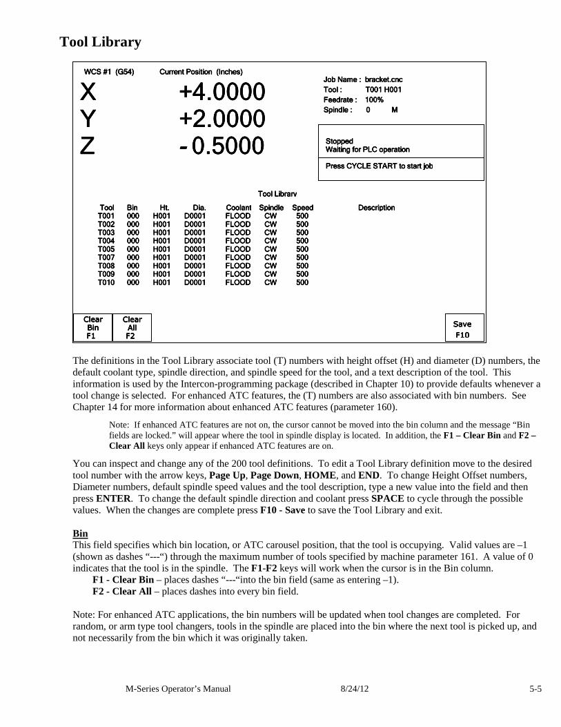
(F2 from Setup) Tool Setup allows you to specify information about the tools you will be using. Press F1 - Offset Library , to edit the Height Offset and Diameter (H and D) values, or F2 - Tool Library to edit the tool descriptions.
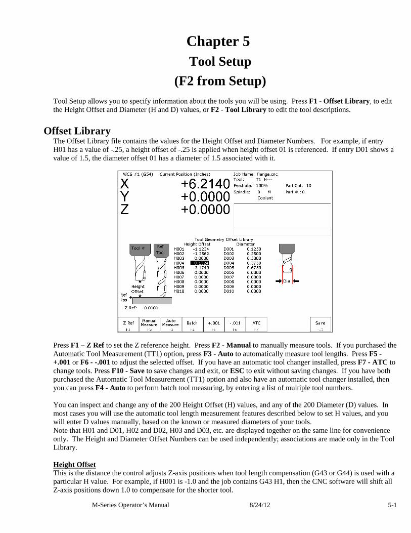
Offset Library The Offset Library file contains the values for the Height Offset and Diameter Numbers. For example, if entry H01 has a value of -.25, a height offset of -.25 is applied when height offset 01 is referenced. If entry D01 shows a value of 1.5, the diameter offset 01 has a diameter of 1.5 associated with it.
Press F1 – Z Ref to set the Z reference height. Press F2 - Manual to manually measure tools. If you purchased the Automatic Tool Measurement (TT1) option, press F3 - Auto to automatically measure tool lengths. Press F5 - +.001 or F6 - -.001 to adjust the selected offset. If you have an automatic tool changer installed, press F7 - ATC to change tools. Press F10 - Save to save changes and exit, or ESC to exit without saving changes. If you have both purchased the Automatic Tool Measurement (TT1) option and also have an automatic tool changer installed, then you can press F4 - Auto to perform batch tool measuring, by entering a list of multiple tool numbers. You can inspect and change any of the 200 Height Offset (H) values, and any of the 200 Diameter (D) values. In most cases you will use the automatic tool length measurement features described below to set H values, and you will enter D values manually, based on the known or measured diameters of your tools. Note that H01 and D01, H02 and D02, H03 and D03, etc. are displayed together on the same line for convenience only. The Height and Diameter Offset Numbers can be used independently; associations are made only in the Tool Library. Height Offset This is the distance the control adjusts Z-axis positions when tool length compensation (G43 or G44) is used with a particular H value. For example, if H001 is -1.0 and the job contains G43 H1, then the CNC software will shift all Z-axis positions down 1.0 to compensate for the shorter tool.
M-Series Operator’s Manual 8/24/12 5-2
To edit the Height Offset entries move to the desired height offset number with the arrow keys, Page Up, Page Down, HOME , and END. You can choose to manually edit or automatically measure the value. Height Offsets values are measured using the Z Reference position. The Z Reference position is the Z-axis position when the tip of the reference tool is touching the work surface. The reference tool should always be the longest tool. The Height Offset value for end mills and drills is the difference between the Z-axis position when the tip of the tool is touching the work surface and the Z Reference position. The Height offset value for ball nose and bull nose cutters is the difference between the Z-axis position when the center of the tool is at the work surface and the Z reference position. Because it is not possible to position the tool in this way, you must instead move the tip of the tool to the work surface, and then manually edit the value to subtract the tool nose radius. To manually edit a Height Offset value, simply type the desired value and press ENTER. To manually measure Height Offset values, use the following procedure: Establishing the Z reference position Press F1 – Z Ref to select the Z Reference setting function. Insert the longest tool into the tool holder (you can use the jog keys or the TOOL CHECK key to assist you). Jog the tip of the tool down to the top of the work surface. Press F10 - Save to save this Z Position as the Reference Position. Measuring each tool height (Z position for tool minus Z position for Reference tool) Insert the desired tool into the tool holder (Jog keys or the TOOL CHECK key can be used to assist you). Jog the tip of the tool down to the top of the work surface. If the tool is a drill or end mill, press F2 –Manual Measure to measure the height. If the tool is a ball nose or bull nose cutter, press F2 – Manual Measure to measure the height, and then subtract the tool nose radius. After a tool height is measured, the next Height Offset entry is automatically selected. When the edit is complete, press F10 - Save to save the Offset Library and Exit. Examples (assuming Z Reference = -1.5): If the tool position is -1.75, then the tool height = -0.25 If the tool position is -1.75 and nose radius is .25, then the tool height = -0.50 If the tool position is -2.25, then the tool height = -0.75 If the tool position is -2.75 and nose radius is .125, then the tool height = -1.375 Diameter This field tells the control the distance to adjust when cutter diameter compensation (G41 or G42) is used with a particular D value. For example, if D001 is 0.5 and the job contains G41 D1, the CNC software will adjust all X-Y positions 0.25 (half the tool diameter) to the left of the programmed tool path. To edit the Diameter entries move to the desired diameter offset number with the arrow keys, Page Up, Page Down, HOME , and END. You must manually edit the Diameter Offset value. Type the desired value and then press the ENTER key. You can make small adjustments to Height Offsets and Diameters using F5 - +.001 and F6 - -.001. Use the arrow keys to highlight the value to be adjusted. Press F5 - +.001 to increase the offset value by 0.001" (or 0.02 mm in Metric mode). Press F6 - -.001 to decrease the offset by the same amount. If the cut parts are undersized, use F5 - +.001 to cut less material. If the cut parts are oversized, use F6 - -.001 to cut more material.
M-Series Operator’s Manual 8/24/12 5-3
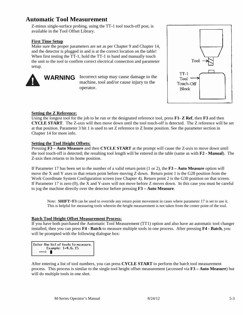
Automatic Tool Measurement Z-minus single-surface probing, using the TT-1 tool touch-off post, is available in the Tool Offset Library. First Time Setup Make sure the proper parameters are set as per Chapter 9 and Chapter 14, and the detector is plugged in and is at the correct location on the table! When first testing the TT-1, hold the TT-1 in hand and manually touch the unit to the tool to confirm correct electrical connection and parameter setup.
WARNING Incorrect setup may cause damage to the
machine, tool and/or cause injury to the operator.
Setting the Z Reference: Using the longest tool for the job to be run or the designated reference tool, press F1- Z Ref, then F3 and then CYCLE START. The Z-axis will then move down until the tool touch-off is detected. The Z reference will be set at that position. Parameter 3 bit 1 is used to set Z reference to Z home position. See the parameter section in Chapter 14 for more info. Setting the Tool Height Offsets: Pressing F3 – Auto Measure and then CYCLE START at the prompt will cause the Z-axis to move down until the tool touch-off is detected; the resulting tool length will be entered in the table (same as with F2 - Manual). The Z-axis then returns to its home position. If Parameter 17 has been set to the number of a valid return point (1 or 2), the F3 – Auto Measure option will move the X and Y axes to that return point before moving Z down. Return point 1 is the G28 position from the Work Coordinate System Configuration screen (see Chapter 4). Return point 2 is the G30 position on that screen. If Parameter 17 is zero (0), the X and Y-axes will not move before Z moves down. In this case you must be careful to jog the machine directly over the detector before pressing F3 – Auto Measure.
Note: SHIFT+F3 can be used to override any return point movement in cases where parameter 17 is set to use it. This is helpful for measuring tools wherein the height measurement is not taken from the center point of the tool.
Batch Tool Height Offset Measurement Process: If you have both purchased the Automatic Tool Measurement (TT1) option and also have an automatic tool changer installed, then you can press F4 - Batch to measure multiple tools in one process. After pressing F4 - Batch, you will be prompted with the following dialogue box:
After entering a list of tool numbers, you can press CYCLE START to perform the batch tool measurement process. This process is similar to the single tool height offset measurement (accessed via F3 – Auto Measure) but will do multiple tools in one shot.
M-Series Operator’s Manual 8/24/12 5-4
Setting up Tool Height Offsets
NOTICE Before manually jogging any probe to a position, make sure the machine Feedrate is turned down (less than 10 in/min) or damage to the probe may result!!!
Using a Probe as the Reference Tool Before you set the Z Reference, make sure the probe Tool # is entered into Parameter 12 on the Machine Parameters screen. Make sure that Parameter 17 on the Machine Parameters screen contains a 0. Follow these steps to probe Z Reference: 1. Load the probe into the machine. 2. Jog the probe over the desired reference surface and press F1 – Z Ref. 3. Press F3 and then CYCLE START; the probe will find the Z Reference. At this point, the Z Reference is now entered into the Offset Library and is the reference height for all other tools. Remove the probe and measure any other tool offsets manually as described earlier in this chapter. Measuring Each Tool Offset Using a Fixed Detector Before measuring any tool height, make sure you enter the probe or reference tool-measuring location. Do this by entering a reference point number (1 or 2) into Parameter 17 and entering the detector position as the corresponding Reference Return Point on the WCS Configuration screen. Otherwise, the machine may traverse to a location that could damage the probe or reference tool. Also remember that if Parameter 17 is zero (0), the X and Y-axes will not move before Z moves down. Also be sure that parameter 44 is set correctly. This is the input number for the TT1. Now that a permanent location has been set, do the following: Load reference tool (preferably the longest tool) and highlight its corresponding Height Offset # using the up or down arrow keys. Press F1 – Z Ref, then F3 – Auto Measure and then CYCLE START to set the Z reference using this tool. The X and Y-axes will traverse to the preset location, and then Z will move down until the tool is detected and the Z reference will be set. Load the next tool. Highlight the desired Height Offset # on screen using the up or down arrow keys. Press F3 – Auto Measure and then CYCLE START. The X and Y-axes will traverse to the preset location, and then Z will move down until the tool is detected. Once the detector is triggered, the tool offset will show on the screen. A negative offset means the tool is shorter than the reference tool. Once all of the tool offsets have been measured, press F10 - Save to save them. Otherwise, press ESC to cancel any changes.
M-Series Operator’s Manual 8/24/12 5-5
Tool Library
The definitions in the Tool Library associate tool (T) numbers with height offset (H) and diameter (D) numbers, the default coolant type, spindle direction, and spindle speed for the tool, and a text description of the tool. This information is used by the Intercon-programming package (described in Chapter 10) to provide defaults whenever a tool change is selected. For enhanced ATC features, the (T) numbers are also associated with bin numbers. See Chapter 14 for more information about enhanced ATC features (parameter 160).
Note: If enhanced ATC features are not on, the cursor cannot be moved into the bin column and the message “Bin fields are locked.” will appear where the tool in spindle display is located. In addition, the F1 – Clear Bin and F2 – Clear All keys only appear if enhanced ATC features are on.
You can inspect and change any of the 200 tool definitions. To edit a Tool Library definition move to the desired tool number with the arrow keys, Page Up, Page Down, HOME , and END. To change Height Offset numbers, Diameter numbers, default spindle speed values and the tool description, type a new value into the field and then press ENTER. To change the default spindle direction and coolant press SPACE to cycle through the possible values. When the changes are complete press F10 - Save to save the Tool Library and exit. Bin This field specifies which bin location, or ATC carousel position, that the tool is occupying. Valid values are –1 (shown as dashes “---“) through the maximum number of tools specified by machine parameter 161. A value of 0 indicates that the tool is in the spindle. The F1-F2 keys will work when the cursor is in the Bin column. F1 - Clear Bin – places dashes “---“into the bin field (same as entering –1). F2 - Clear All – places dashes into every bin field. Note: For enhanced ATC applications, the bin numbers will be updated when tool changes are completed. For random, or arm type tool changers, tools in the spindle are placed into the bin where the next tool is picked up, and not necessarily from the bin which it was originally taken.
WCS #1 (G54) Current Position (Inches) WCS #1 (G54) Current Position (Inches) WCS #1 (G54) Current Position (Inches) WCS #1 (G54) Current Position (Inches)
X X X X +4.0000+4.0000+4.0000+4.0000 Y +2.0000Y +2.0000Y +2.0000Y +2.0000 ZZZZ ---- 0.50000.50000.50000.5000
Job Name : Job Name : Job Name : Job Name : bbbbracket.cncracket.cncracket.cncracket.cnc
Tool : Tool : Tool : Tool : T001 H001T001 H001T001 H001T001 H001
Feedrate : 100%Feedrate : 100%Feedrate : 100%Feedrate : 100%
Spindle : 0 M Spindle : 0 M Spindle : 0 M Spindle : 0 M
StoppedStoppedStoppedStopped Waiting for PLC operationWaiting for PLC operationWaiting for PLC operationWaiting for PLC operation StoppedStoppedStoppedStopped PresPresPresPress CYCLE START to start jobs CYCLE START to start jobs CYCLE START to start jobs CYCLE START to start job
Clear Clear Clear Clear
BinBinBinBin
FFFF1111
Clear Clear Clear Clear
AllAllAllAll
FFFF2222
Tool Tool Tool Tool BinBinBinBin Ht.Ht.Ht.Ht. Dia.Dia.Dia.Dia. CoolantCoolantCoolantCoolant SpindleSpindleSpindleSpindle SpeedSpeedSpeedSpeed DescriptionDescriptionDescriptionDescription T001T001T001T001 000 H001 D0001 FLOOD CW 500000 H001 D0001 FLOOD CW 500000 H001 D0001 FLOOD CW 500000 H001 D0001 FLOOD CW 500 T002 T002 T002 T002 000 H001 D0001 FLOOD CW 500000 H001 D0001 FLOOD CW 500000 H001 D0001 FLOOD CW 500000 H001 D0001 FLOOD CW 500 T003 T003 T003 T003 000 H001 D0001 FLOOD 000 H001 D0001 FLOOD 000 H001 D0001 FLOOD 000 H001 D0001 FLOOD CW 500CW 500CW 500CW 500 T004 T004 T004 T004 000 H001 D0001 FLOOD CW 500000 H001 D0001 FLOOD CW 500000 H001 D0001 FLOOD CW 500000 H001 D0001 FLOOD CW 500 T005 T005 T005 T005 000 H001 D0001 FLOOD CW 500000 H001 D0001 FLOOD CW 500000 H001 D0001 FLOOD CW 500000 H001 D0001 FLOOD CW 500 T007 T007 T007 T007 000 H001 D0001 FLOOD CW 500000 H001 D0001 FLOOD CW 500000 H001 D0001 FLOOD CW 500000 H001 D0001 FLOOD CW 500 T008 T008 T008 T008 000 H001 000 H001 000 H001 000 H001 D0001 FLOOD CW 500 D0001 FLOOD CW 500 D0001 FLOOD CW 500 D0001 FLOOD CW 500 T009 T009 T009 T009 000 H001 D0001 FLOOD CW 500000 H001 D0001 FLOOD CW 500000 H001 D0001 FLOOD CW 500000 H001 D0001 FLOOD CW 500 T010 T010 T010 T010 000 H001 D0001 FLOOD CW 500000 H001 D0001 FLOOD CW 500000 H001 D0001 FLOOD CW 500000 H001 D0001 FLOOD CW 500
Tool LibrarTool LibrarTool LibrarTool Libraryyyy
Save Save Save Save
FFFF10101010
M-Series Operator’s Manual 8/24/12 5-6
Height This field specifies a default Height Offset (H) number to use with each tool. Possible values are 1 to 200. Intercon uses this information to provide a default H value at each tool change. The CNC software also uses this information to correct for the length of the tool that is used to establish the Z-axis position in Part Setup (see Chapter 5). Diameter This field specifies a default Diameter (D) number to use with each tool. Possible values are 1 to 200. Intercon uses this information to provide a default D value at each tool change. To change the value type a new number and press ENTER. Coolant This field specifies a default coolant type to use with each tool. Possible values are FLOOD, MIST, or OFF. Intercon uses this information to automatically insert M7 or M8 after a tool change. To change the value, press SPACE until the desired value is shown. Spindle This field specifies a default spindle direction to use with each tool. Possible values are CW, CCW, or OFF. Intercon uses this information to automatically insert M3 or M4 after a tool change. To change the value, press SPACE until the desired value is shown. Speed This field specifies a default spindle speed to use with each tool. Possible values are 0 to 500000. Intercon uses this information to automatically insert an S code after a tool change. To change the value, type a new number and press ENTER. Description This field contains a text description of the tool. The description will appear in a prompt message on the screen when the CNC software reaches a tool change (M6).
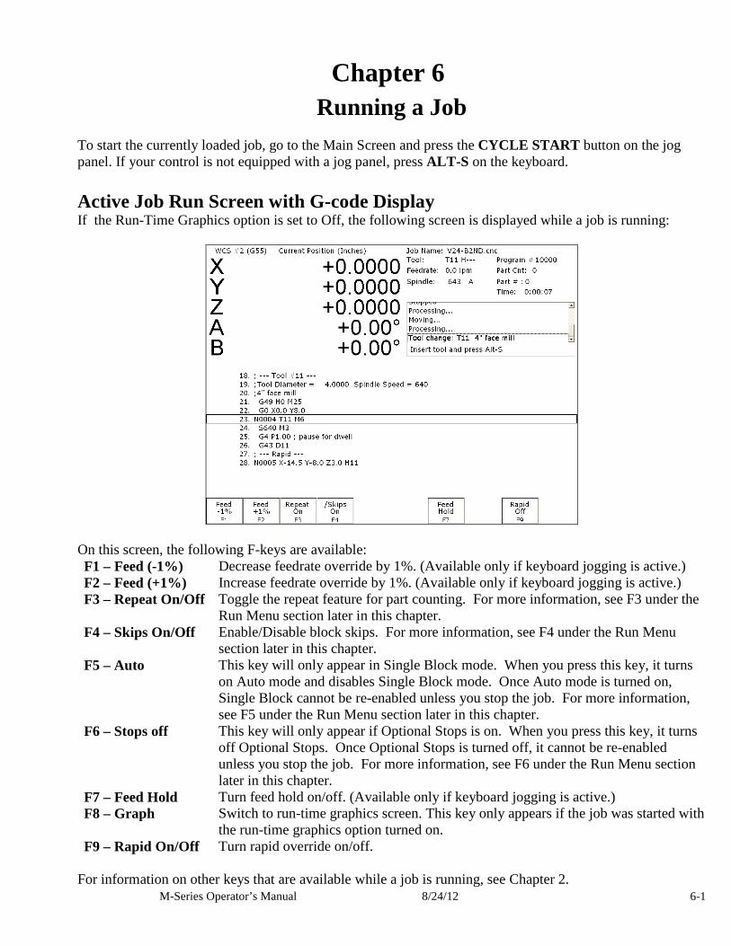
M-Series Operator’s Manual 8/24/12 6-1
Chapter 6 Running a Job
To start the currently loaded job, go to the Main Screen and press the CYCLE START button on the jog panel. If your control is not equipped with a jog panel, press ALT-S on the keyboard.
Active Job Run Screen with G-code Display If the Run-Time Graphics option is set to Off, the following screen is displayed while a job is running:
On this screen, the following F-keys are available: F1 – Feed (-1%) Decrease feedrate override by 1%. (Available only if keyboard jogging is active.) F2 – Feed (+1%) Increase feedrate override by 1%. (Available only if keyboard jogging is active.) F3 – Repeat On/Off Toggle the repeat feature for part counting. For more information, see F3 under the
Run Menu section later in this chapter. F4 – Skips On/Off Enable/Disable block skips. For more information, see F4 under the Run Menu
section later in this chapter. F5 – Auto This key will only appear in Single Block mode. When you press this key, it turns
on Auto mode and disables Single Block mode. Once Auto mode is turned on, Single Block cannot be re-enabled unless you stop the job. For more information, see F5 under the Run Menu section later in this chapter.
F6 – Stops off This key will only appear if Optional Stops is on. When you press this key, it turns off Optional Stops. Once Optional Stops is turned off, it cannot be re-enabled unless you stop the job. For more information, see F6 under the Run Menu section later in this chapter.
F7 – Feed Hold Turn feed hold on/off. (Available only if keyboard jogging is active.) F8 – Graph Switch to run-time graphics screen. This key only appears if the job was started with
the run-time graphics option turned on. F9 – Rapid On/Off Turn rapid override on/off.
For information on other keys that are available while a job is running, see Chapter 2.
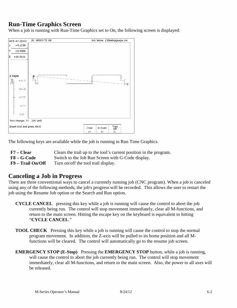
M-Series Operator’s Manual 8/24/12 6-2
Run-Time Graphics Screen When a job is running with Run-Time Graphics set to On, the following screen is displayed:
The following keys are available while the job is running in Run Time Graphics. F7 – Clear Clears the trail up to the tool’s current position in the program. F8 – G-Code Switch to the Job Run Screen with G-Code display. F9 – Trail On/Off Turn on/off the tool trail display.
Canceling a Job in Progress There are three conventional ways to cancel a currently running job (CNC program). When a job is canceled using any of the following methods, the job's progress will be recorded. This allows the user to restart the job using the Resume Job option or the Search and Run option.
CYCLE CANCEL pressing this key while a job is running will cause the control to abort the job currently being run. The control will stop movement immediately, clear all M-functions, and return to the main screen. Hitting the escape key on the keyboard is equivalent to hitting “CYCLE CANCEL .”
TOOL CHECK Pressing this key while a job is running will cause the control to stop the normal
program movement. In addition, the Z-axis will be pulled to its home position and all M-functions will be cleared. The control will automatically go to the resume job screen.
EMERGENCY STOP (E-Stop) Pressing the EMERGENCY STOP button, while a job is running,
will cause the control to abort the job currently being run. The control will stop movement immediately, clear all M-functions, and return to the main screen. Also, the power to all axes will be released.
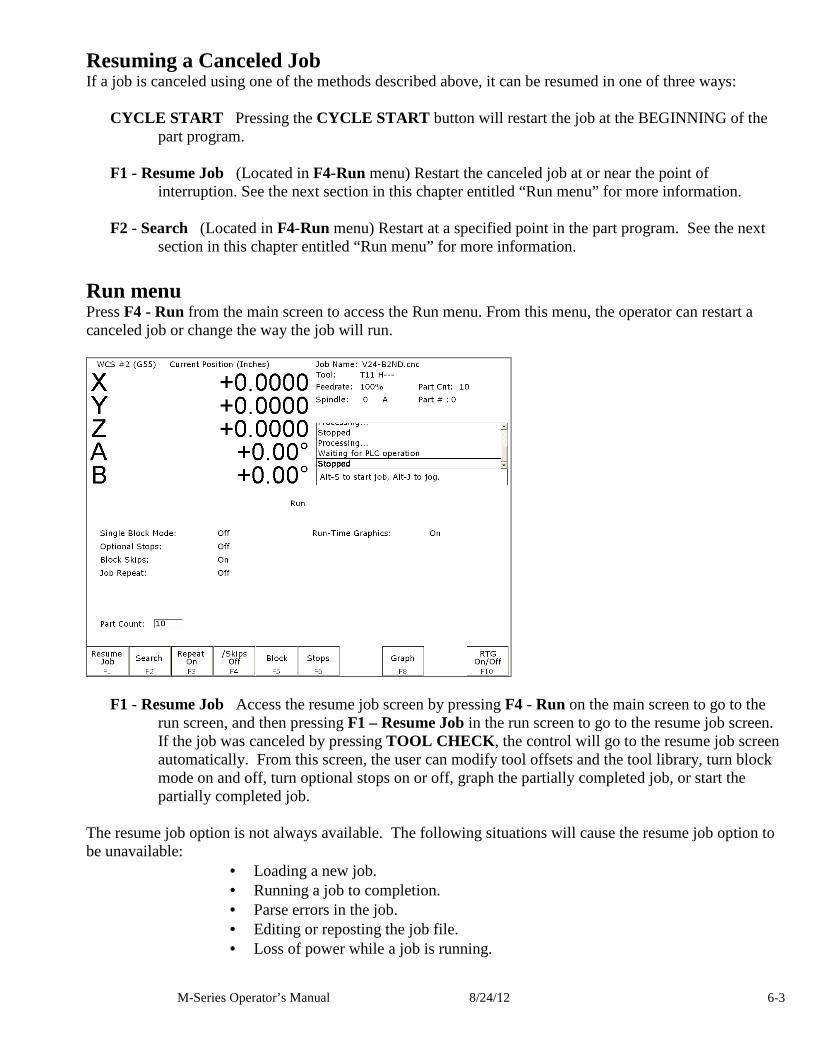
M-Series Operator’s Manual 8/24/12 6-3
Resuming a Canceled Job If a job is canceled using one of the methods described above, it can be resumed in one of three ways:
CYCLE START Pressing the CYCLE START button will restart the job at the BEGINNING of the part program.
F1 - Resume Job (Located in F4-Run menu) Restart the canceled job at or near the point of
interruption. See the next section in this chapter entitled “Run menu” for more information.
F2 - Search (Located in F4-Run menu) Restart at a specified point in the part program. See the next section in this chapter entitled “Run menu” for more information.
Run menu Press F4 - Run from the main screen to access the Run menu. From this menu, the operator can restart a canceled job or change the way the job will run.
F1 - Resume Job Access the resume job screen by pressing F4 - Run on the main screen to go to the run screen, and then pressing F1 – Resume Job in the run screen to go to the resume job screen. If the job was canceled by pressing TOOL CHECK , the control will go to the resume job screen automatically. From this screen, the user can modify tool offsets and the tool library, turn block mode on and off, turn optional stops on or off, graph the partially completed job, or start the partially completed job.
The resume job option is not always available. The following situations will cause the resume job option to be unavailable:
• Loading a new job. • Running a job to completion. • Parse errors in the job. • Editing or reposting the job file. • Loss of power while a job is running.
M-Series Operator’s Manual 8/24/12 6-4
F2 – Search Invoking this option will bring you to the “Search and Run” menu. This menu will allow
you to specify the program line, block number, or tool number at which execution of a program is to begin. Program lines are numbered from the top of the file down with the first line numbered 1. To enter a block number, place an "N" in front of the number. To enter a tool number, place a "T" in front of the number. Pressing CYCLE START from here would start the program at the point you specified. An extra option unique to the “Search and Run” screen is the F1 – Tool Change “Do Last Tool Change” function. This key toggles the tool change option as shown on screen. A "YES" tells the control to perform a tool change so that the tool specified for the line or block has the tool indicated in the program. A "NO" uses the currently loaded tool, regardless of what tool is specified for the line or block being searched.
NOTE: You cannot search into a subroutine.
F3 – Repeat On/Off This key toggles the repeat feature for part counting. When part counting is in effect and Repeat is on, the job will be automatically run again until the specified number of parts has been run. The On or Off label indicates the state to which the repeat feature will toggle to when pressed. It does not indicate the current state. The current state is indicated in the user window above.
The Part Count: prompt is used to set the Part count. Positive values set the part counter to count up and negative values configure the part count to count down. For example, if 10 is entered in the Part Count prompt, the Part Cnt in the status window changes to 10 and the Part # changes to 0 with an upward arrow indicator. When a job is run and then completes, the Part # will increment to 1. If repeat is on, the job will automatically start again and keep running until the Part # has reached the Part Cnt. If a –10 is entered in the Part Count prompt, the Part Cnt in the status window changes to 10 and the Part # changes to 10 with a downward arrow indicator. When a job is finished, the Part # will decremented to 9. If repeat is on, the job will automatically start again and keep running until the Part # has reached 0.
F4 - /Skips On/Off This function toggles the block skip feature. When block skipping is on, G-code lines that start with a forward slash character ‘/’ are skipped, i.e., they are not processed. Note that because of the way a job is processed (in a pre-processed buffered fashion) the effect of this key may be delayed if you press it while a job is running. The On or Off label indicates the state to which the /Skips feature will toggle to when pressed. It does not indicate the current state. The current state is indicated in the user window above.
F5 - Block Mode Turns single block mode on and off. This is similar to pressing AUTO/BLOCK . If
Single Block mode is on, the CNC software will stop after each block in your part program and wait for you to press CYCLE START . Note that Auto mode is the default mode. If you use this key to turn on Single Block mode and then run a job, Auto mode will be re-instated when the job ends. The current state of this setting is indicated in the user window above.
F6 - Optional Stops Turns optional stops on and off. If optional stops are on, any M1 codes that
appear in your program will cause a wait for CYCLE START (just like M0). If optional stops are off, M1 codes will be ignored. Note that the default mode for Optional Stops is off. If you use this key to turn on Single Block mode and then run a job, Optional Stops will be set to off when the job ends. The current state of this setting is indicated in the user window above.
M-Series Operator’s Manual 8/24/12 6-5
F8 – Graph Graphs the part. For more information, see the "F8 - Graph" section in chapter 3. If this feature is invoked from the Run and Search screen or the Resume Job screen, then the graphics will show exactly where the searched line or block begins. Dotted lines indicate the portion of the part that is skipped. Solid lines indicate the portion of the part that will be machined.
F9 – Rapid On/Off This function key toggles Rapid Override. The On or Off label indicates the state
to which the Rapid Override feature will toggle to when pressed. It does not indicate the current state. It has the same effect as the Rapid Over key discussed in Chapter 2.
F10 – RTG On/Off This function key toggles the Run-Time Graphics option. If the option is turned
on, Run-Time Graphics automatically starts when the CYCLE START button is pressed. This option must be turned on for Run-Time Graphics to be used. If the option is turned off, Run-Time Graphics cannot be started while a job is running.
Power Feed Press F4 - Feed from the Setup menu to access the Power Feed screen. This screen is used to command axis movement. All the operations available on the Power Feed screen may also be performed in MDI with the appropriate M and G codes.
F1 - Absolute Power Feed Press F1 - ABS to move an axis to an absolute position, at a specified feedrate.
F2 - Incremental Power Feed Press F2 - INC to move an axis an incremental distance, at a specified
feedrate.
F3 - Free XY Press F3 - Free to release power to the X and Y motors, allowing you to use your machine manually for these two axes.
F4 - Power XY Press F4 - Power to apply power to the X and Y motors, allowing you to use your
machine with the jog panel for these two axes.

M-Series Operator’s Manual 8/24/12 6-6
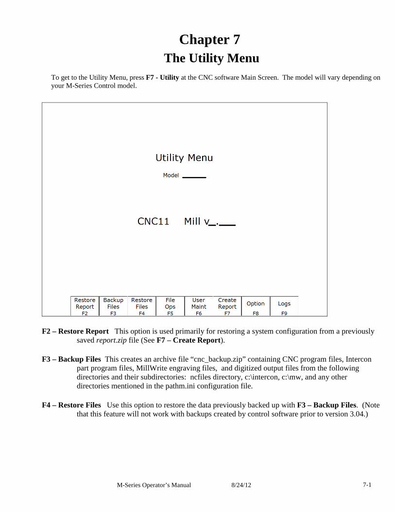
M-Series Operator’s Manual 8/24/12 7-1
Chapter 7 The Utility Menu
To get to the Utility Menu, press F7 - Utility at the CNC software Main Screen. The model will vary depending on your M-Series Control model.
F2 – Restore Report This option is used primarily for restoring a system configuration from a previously saved report.zip file (See F7 – Create Report).
F3 – Backup Files This creates an archive file “cnc_backup.zip” containing CNC program files, Intercon part program files, MillWrite engraving files, and digitized output files from the following directories and their subdirectories: ncfiles directory, c:\intercon, c:\mw, and any other directories mentioned in the pathm.ini configuration file.
F4 – Restore Files Use this option to restore the data previously backed up with F3 – Backup Files. (Note that this feature will not work with backups created by control software prior to version 3.04.)
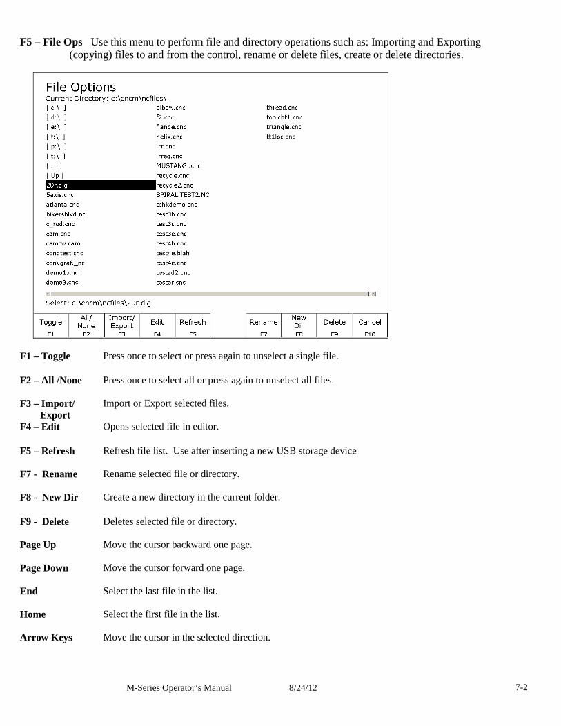
M-Series Operator’s Manual 8/24/12 7-2
F5 – File Ops Use this menu to perform file and directory operations such as: Importing and Exporting (copying) files to and from the control, rename or delete files, create or delete directories.
F1 – Toggle
Press once to select or press again to unselect a single file.
F2 – All /None Press once to select all or press again to unselect all files.
F3 – Import/ Export
Import or Export selected files.
F4 – Edit
Opens selected file in editor.
F5 – Refresh Refresh file list. Use after inserting a new USB storage device
F7 - Rename Rename selected file or directory.
F8 - New Dir
Create a new directory in the current folder.
F9 - Delete Deletes selected file or directory.
Page Up Move the cursor backward one page.
Page Down Move the cursor forward one page.
End Select the last file in the list.
Home Select the first file in the list.
Arrow Keys Move the cursor in the selected direction.
M-Series Operator’s Manual 8/24/12 7-3
F6 – User Maint Use this menu to perform user maintenance such as checking an axis for excessive drag or setting backlash F1 – Drag The Drag Factor utility is used to determine if an axis has an excessive amount of drag. To
run a drag test, use the F1 key to select the axis which you wish to test, position the axis at or near the home position and press CYCLE START . The axis will move back to the home switch then traverse the entire range of travel for the axis moving to the opposite limit and returning to home while moving the slow jog rate. If excessive friction (drag) is encountered an error message will be displayed. When the test completes, use F8-Graph to display the results. The red horizontal lines indicate the bounds acceptable limits for the machine as it is currently configured.
F2 - Lash (Backlash Compensation) In order to insure an accurate measurement always set the backlash compensation in the control to zero before attempting to measure the physical lash in an axis.
F7 – Create Report Generates a backup of system configuration files called report.zip and copies it to the
specified location. Your dealer may then use this file for servicing and troubleshooting purposes. To restore the configuration files from the report disk, press F2 – Restore Report from the Utility menu.
F8 – Options Shows the software options that you have purchased or added to your control. On this screen you can also enter unlock codes for software options that you have purchased. This page will also display the PLC programs, PIC type, and System ID #.
F9 – Logs Shows the messages and errors that have been logged by the control. F1 – Errors Displays the error/message log. Use PgUp, PgDn, Home, & End to view and ESC to exit. F2 – Stats Displays counts of errors logged. Use PgUp, PgDn, Home, & End to view and ESC to exit. F3 – Export Exports the log to a destination of your choosing.

M-Series Operator’s Manual 8/24/12 7-4
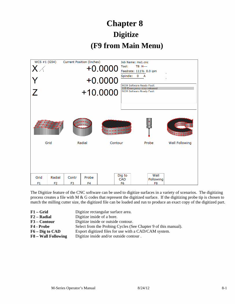
M-Series Operator’s Manual 8/24/12 8-1
Chapter 8 Digitize
(F9 from Main Menu)
The Digitize feature of the CNC software can be used to digitize surfaces in a variety of scenarios. The digitizing process creates a file with M & G codes that represent the digitized surface. If the digitizing probe tip is chosen to match the milling cutter size, the digitized file can be loaded and run to produce an exact copy of the digitized part. F1 – Grid Digitize rectangular surface area. F2 – Radial Digitize inside of a bore. F3 – Contour Digitize inside or outside contour. F4 - Probe Select from the Probing Cycles (See Chapter 9 of this manual). F6 – Dig to CAD Export digitized files for use with a CAD/CAM system. F8 – Wall Following Digitize inside and/or outside contour .
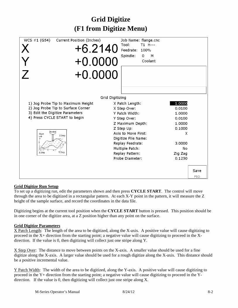
M-Series Operator’s Manual 8/24/12 8-2
Grid Digitize (F1 from Digitize Menu)
Grid Digitize Run Setup To set up a digitizing run, edit the parameters shown and then press CYCLE START. The control will move through the area to be digitized in a rectangular pattern. At each X-Y point in the pattern, it will measure the Z height of the sample surface, and record the coordinates in the data file. Digitizing begins at the current tool position when the CYCLE START button is pressed. This position should be in one corner of the digitize area, at a Z position higher than any point on the surface. Grid Digitize Parameters X Patch Length: The length of the area to be digitized, along the X-axis. A positive value will cause digitizing to proceed in the X+ direction from the starting point; a negative value will cause digitizing to proceed in the X- direction. If the value is 0, then digitizing will collect just one stripe along Y. X Step Over: The distance to move between points on the X-axis. A smaller value should be used for a fine digitize along the X-axis. A larger value should be used for a rough digitize along the X-axis. This distance should be a positive incremental value. Y Patch Width: The width of the area to be digitized, along the Y-axis. A positive value will cause digitizing to proceed in the Y+ direction from the starting point; a negative value will cause digitizing to proceed in the Y- direction. If the value is 0, then digitizing will collect just one stripe along X.
M-Series Operator’s Manual 8/24/12 8-3
Y Step Over: The distance to move between points on the Y-axis. A smaller value should be used for a fine digitize along the Y-axis. A larger value should be used for a rough digitize along the Y-axis. This distance should be a positive incremental value. Z Maximum Depth: The maximum distance the Z-axis moves below the starting height. If the probe does not contact the surface at the maximum depth, that data point will be recorded as being at the maximum depth, and digitizing will proceed with the next point. Z Step Up: The distance the Z-axis moves up after making contact, before the control attempts to move X or Y. A small value should be used when digitizing parts with gentle slopes; a larger value should be used when digitizing parts with many steep walls. Axis to Move First: The axis (either X or Y) which moves all the way across the digitize area with each pass. Digitize File Name: The base name of the output file in which the digitize data is stored. An extension of .dig will automatically be appended to the name for replay as a CNC job. Replay Feedrate: The feedrate to include with the G1 command on the first line of the data file. If the data file is run as a CNC program, this is the feedrate at which the machine will retrace the digitized surface. Multiple Patch: Indicates whether or not this digitizing is a continuation of an earlier digitizing. Choose NO if the current digitizing is the first or only digitize run for the part to be digitized. Choose YES if the current digitizing is not the first digitize run for the part. If Yes is selected, specify the name of a digitize file of a previous multiple patch. Replay Pattern: Indicates the replay movement pattern. If ZIG ZAG is selected, the replay pattern will alternate between positive and negative directions on each successive pass. If ONE WAY is selected, the replay pattern will maintain a constant "one-way" direction throughout the playback. Probe Diameter: Indicates the probe tip diameter.
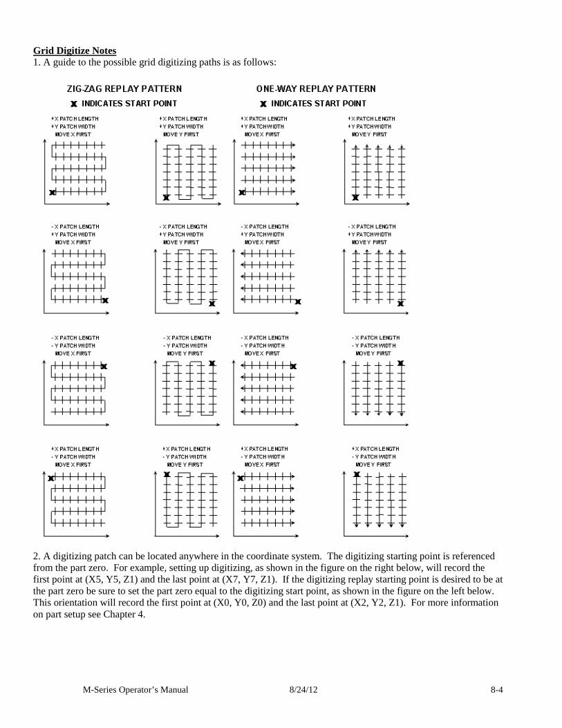
M-Series Operator’s Manual 8/24/12 8-4
Grid Digitize Notes 1. A guide to the possible grid digitizing paths is as follows:
2. A digitizing patch can be located anywhere in the coordinate system. The digitizing starting point is referenced from the part zero. For example, setting up digitizing, as shown in the figure on the right below, will record the first point at (X5, Y5, Z1) and the last point at (X7, Y7, Z1). If the digitizing replay starting point is desired to be at the part zero be sure to set the part zero equal to the digitizing start point, as shown in the figure on the left below. This orientation will record the first point at (X0, Y0, Z0) and the last point at (X2, Y2, Z1). For more information on part setup see Chapter 4.
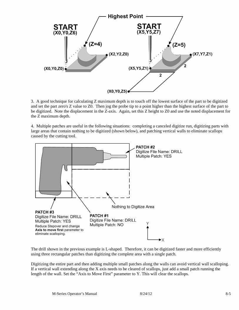
M-Series Operator’s Manual 8/24/12 8-5
3. A good technique for calculating Z maximum depth is to touch off the lowest surface of the part to be digitized and set the part zero's Z value to Z0. Then jog the probe tip to a point higher than the highest surface of the part to be digitized. Note the displacement in the Z-axis. Again, set this Z height to Z0 and use the noted displacement for the Z maximum depth. 4. Multiple patches are useful in the following situations: completing a canceled digitize run, digitizing parts with large areas that contain nothing to be digitized (shown below), and patching vertical walls to eliminate scallops caused by the cutting tool.
The drill shown in the previous example is L-shaped. Therefore, it can be digitized faster and more efficiently using three rectangular patches than digitizing the complete area with a single patch. Digitizing the entire part and then adding multiple small patches along the walls can avoid vertical wall scalloping. If a vertical wall extending along the X axis needs to be cleared of scallops, just add a small patch running the length of the wall. Set the “Axis to Move First” parameter to Y. This will clear the scallops.
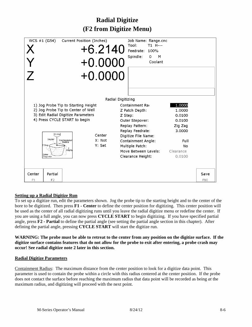
M-Series Operator’s Manual 8/24/12 8-6
Radial Digitize (F2 from Digitize Menu)
Setting up a Radial Digitize Run To set up a digitize run, edit the parameters shown. Jog the probe tip to the starting height and to the center of the bore to be digitized. Then press F1 - Center to define the center position for digitizing. This center position will be used as the center of all radial digitizing runs until you leave the radial digitize menu or redefine the center. If you are using a full angle, you can now press CYCLE START to begin digitizing. If you have specified partial angle, press F2 - Partial to define the partial angle (see setting the partial angle section in this chapter). After defining the partial angle, pressing CYCLE START will start the digitize run. WARNING: The probe must be able to retreat to the center from any position on the digitize surface. If the digitize surface contains features that do not allow for the probe to exit after entering, a probe crash may occur! See radial digitize note 2 later in this section. Radial Digitize Parameters Containment Radius: The maximum distance from the center position to look for a digitize data point. This parameter is used to contain the probe within a circle with this radius centered at the center position. If the probe does not contact the surface before reaching the maximum radius that data point will be recorded as being at the maximum radius, and digitizing will proceed with the next point.

M-Series Operator’s Manual 8/24/12 8-7
Z Patch Depth: The depth of the patch to be digitized, along the Z-axis. A positive value will cause digitizing to proceed in the Z+ direction from the starting point; a negative value will cause digitizing to proceed in the Z- direction. Z Step: The distance to move between points on the Z-axis. A smaller value should be used for a fine digitize along the Z-axis. A larger value should be used for a rough digitize along the Z-axis. This distance should be a positive incremental value. Outer Stepover: The distance to move between points on one contour. A smaller value should be used for a fine digitize along any one contour. A larger value should be used for a rough digitize along any one contour. This distance should be a positive incremental value. Replay Pattern: Indicates the replay movement pattern. If Zigzag is selected, the replay pattern will alternate between positive and negative angle directions (CW and CCW) on each successive contour. If CW or CCW is selected, the replay pattern will maintain a constant angle direction throughout the playback. Replay Feedrate: The feedrate to include with the G1 command on the first line of the data file. If the data file is run as a CNC program, this is the feedrate at which the machine will retrace the digitized surface. Digitize File Name: The base name of the file in which the digitize data is stored. The file has an extension of .dig for CNC replay. Containment Angle: Indicates whether or not the digitizing is to follow a full circle or a partial sector. Choose Full if 0 to 360 degrees is desired. Choose Partial if some other angles are needed. These partial angles can then be changed later (see setting the Partial Digitizing Sector Setup section that follows). Multiple Patch: Indicates whether or not this digitizing is a continuation of an earlier digitizing. Choose No if the current digitizing is the first or only digitize run for the part to be digitized. Choose Yes if the current digitizing is not the first digitize run for the part. If Yes is selected, specify the name of a digitize file of a previous multiple patch. Move Between Levels: This field is enabled only if Partial and CCW or CW option is selected. It indicates the move between Z levels on replay of a partial sector radial digitize file. This move may now be done in three different ways: Clearance, which goes to the clearance height as in previous versions, Center, which goes to the digitizing center and then to the Z level of the next pass, and Direct, which goes directly to the starting point of the next pass. Clearance Height: This field is enabled only if Partial, CCW or CW replay pattern, and Clearance Move type option is selected. This distance indicates the clearance height needed to move the cutter from the end of one contour to the beginning of the next contour. This distance should be a positive value.
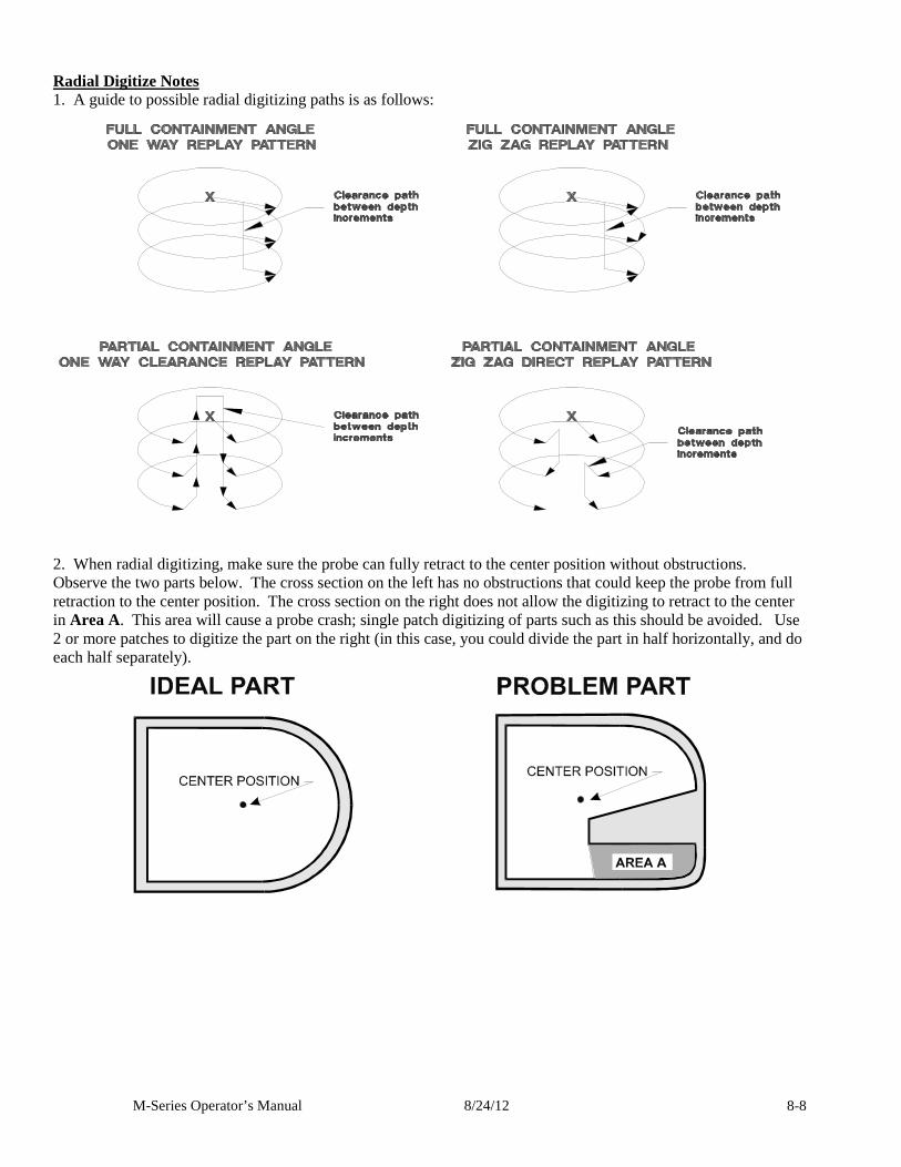
M-Series Operator’s Manual 8/24/12 8-8
Radial Digitize Notes 1. A guide to possible radial digitizing paths is as follows:
2. When radial digitizing, make sure the probe can fully retract to the center position without obstructions. Observe the two parts below. The cross section on the left has no obstructions that could keep the probe from full retraction to the center position. The cross section on the right does not allow the digitizing to retract to the center in Area A. This area will cause a probe crash; single patch digitizing of parts such as this should be avoided. Use 2 or more patches to digitize the part on the right (in this case, you could divide the part in half horizontally, and do each half separately).
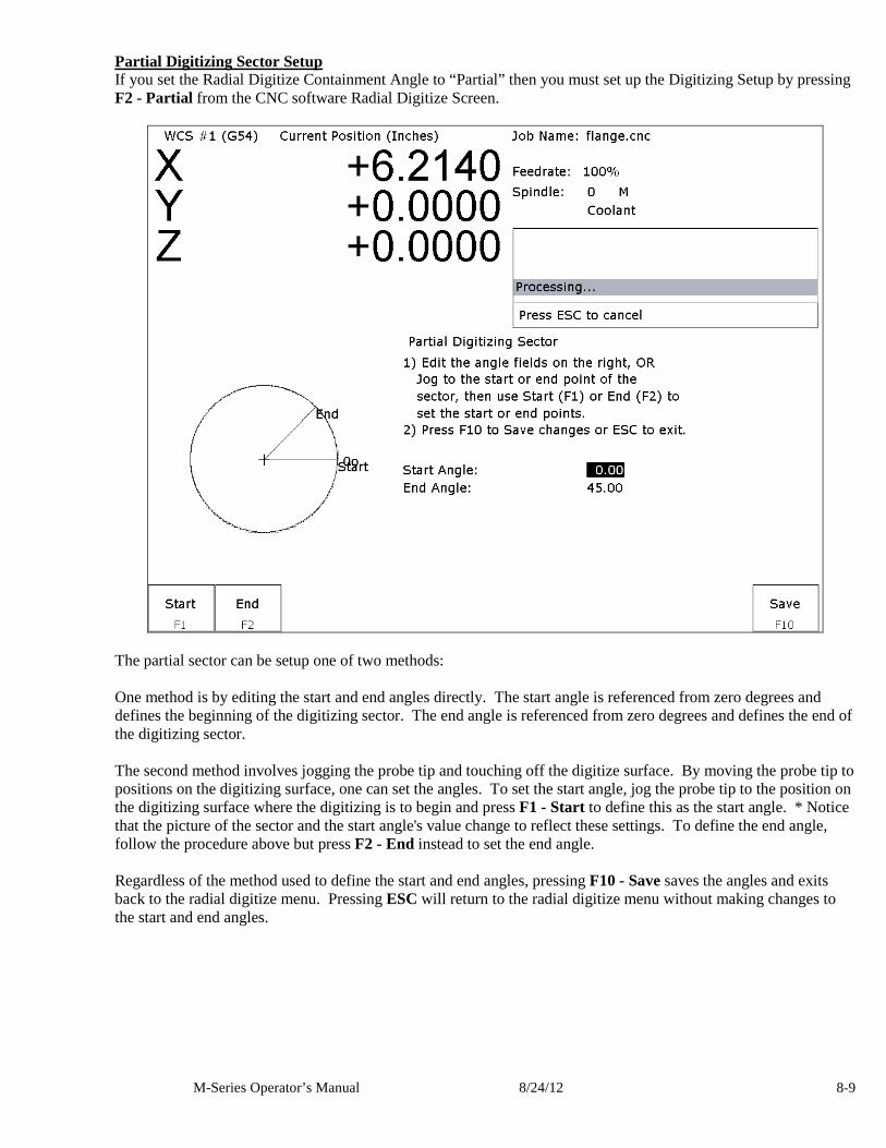
M-Series Operator’s Manual 8/24/12 8-9
Partial Digitizing Sector Setup If you set the Radial Digitize Containment Angle to “Partial” then you must set up the Digitizing Setup by pressing F2 - Partial from the CNC software Radial Digitize Screen.
The partial sector can be setup one of two methods: One method is by editing the start and end angles directly. The start angle is referenced from zero degrees and defines the beginning of the digitizing sector. The end angle is referenced from zero degrees and defines the end of the digitizing sector. The second method involves jogging the probe tip and touching off the digitize surface. By moving the probe tip to positions on the digitizing surface, one can set the angles. To set the start angle, jog the probe tip to the position on the digitizing surface where the digitizing is to begin and press F1 - Start to define this as the start angle. * Notice that the picture of the sector and the start angle's value change to reflect these settings. To define the end angle, follow the procedure above but press F2 - End instead to set the end angle. Regardless of the method used to define the start and end angles, pressing F10 - Save saves the angles and exits back to the radial digitize menu. Pressing ESC will return to the radial digitize menu without making changes to the start and end angles.
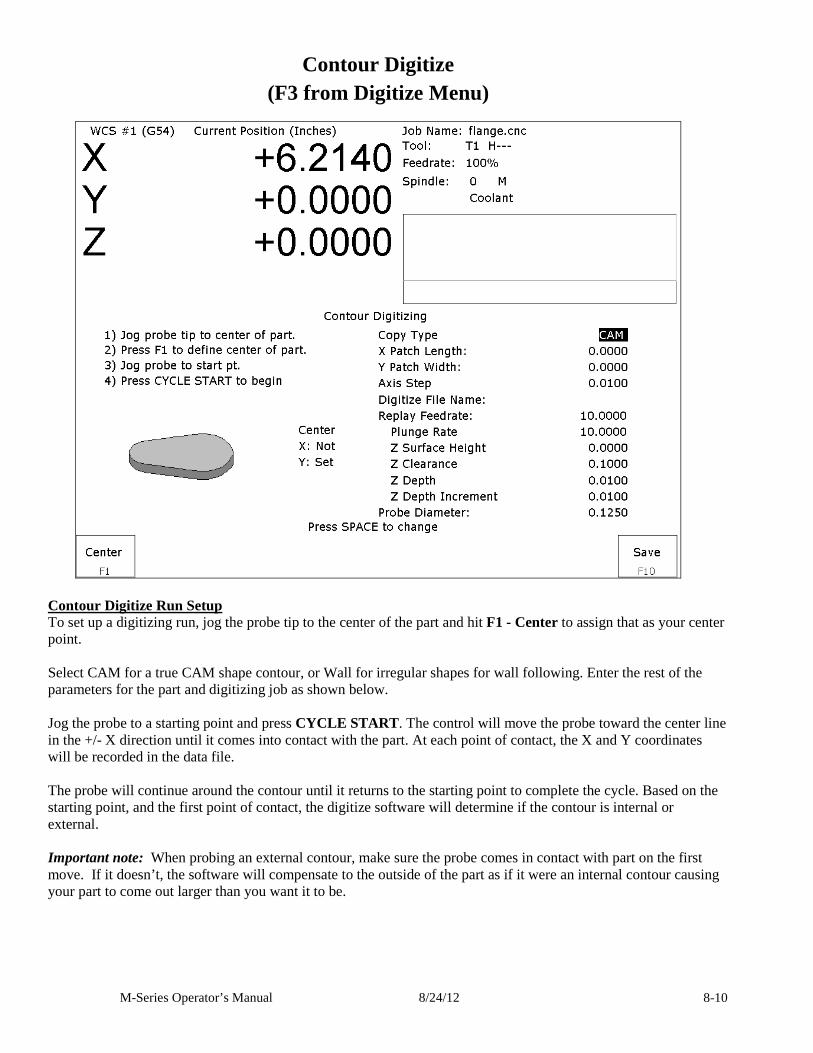
M-Series Operator’s Manual 8/24/12 8-10
Contour Digitize (F3 from Digitize Menu)
Contour Digitize Run Setup To set up a digitizing run, jog the probe tip to the center of the part and hit F1 - Center to assign that as your center point. Select CAM for a true CAM shape contour, or Wall for irregular shapes for wall following. Enter the rest of the parameters for the part and digitizing job as shown below. Jog the probe to a starting point and press CYCLE START. The control will move the probe toward the center line in the +/- X direction until it comes into contact with the part. At each point of contact, the X and Y coordinates will be recorded in the data file. The probe will continue around the contour until it returns to the starting point to complete the cycle. Based on the starting point, and the first point of contact, the digitize software will determine if the contour is internal or external. Important note: When probing an external contour, make sure the probe comes in contact with part on the first move. If it doesn’t, the software will compensate to the outside of the part as if it were an internal contour causing your part to come out larger than you want it to be.
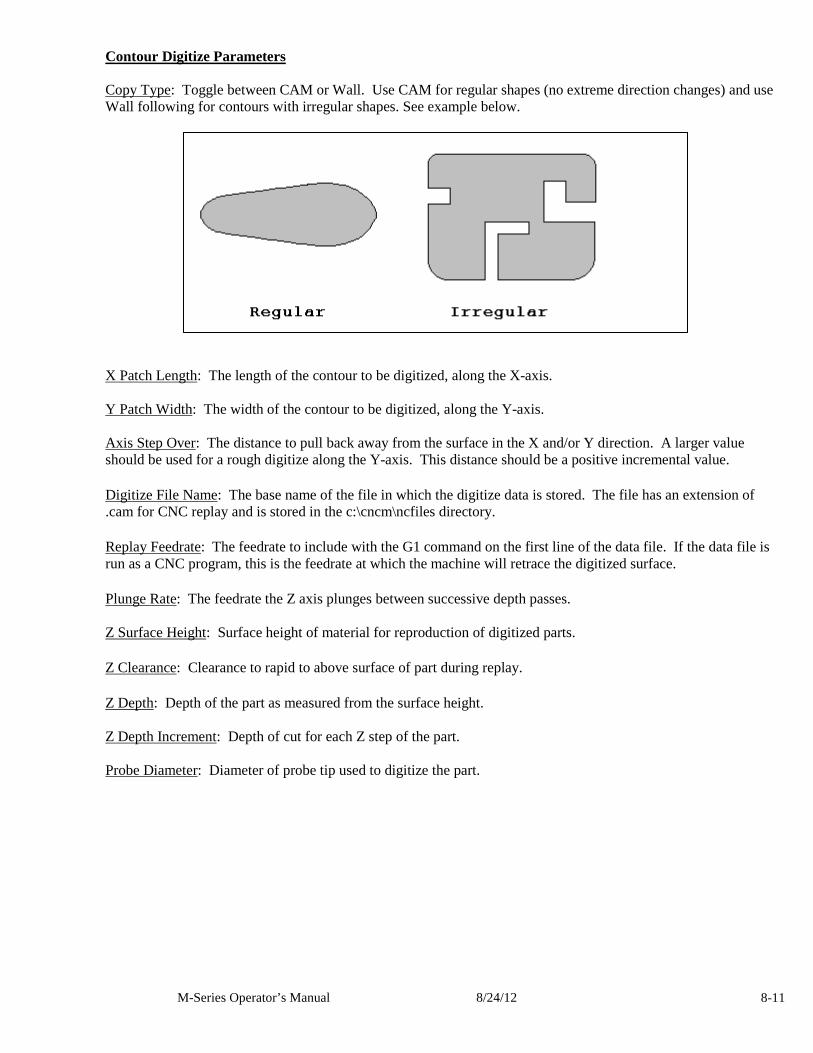
M-Series Operator’s Manual 8/24/12 8-11
Contour Digitize Parameters Copy Type: Toggle between CAM or Wall. Use CAM for regular shapes (no extreme direction changes) and use Wall following for contours with irregular shapes. See example below.
X Patch Length: The length of the contour to be digitized, along the X-axis. Y Patch Width: The width of the contour to be digitized, along the Y-axis. Axis Step Over: The distance to pull back away from the surface in the X and/or Y direction. A larger value should be used for a rough digitize along the Y-axis. This distance should be a positive incremental value.
Digitize File Name: The base name of the file in which the digitize data is stored. The file has an extension of .cam for CNC replay and is stored in the c:\cncm\ncfiles directory.
Replay Feedrate: The feedrate to include with the G1 command on the first line of the data file. If the data file is run as a CNC program, this is the feedrate at which the machine will retrace the digitized surface.
Plunge Rate: The feedrate the Z axis plunges between successive depth passes. Z Surface Height: Surface height of material for reproduction of digitized parts.
Z Clearance: Clearance to rapid to above surface of part during replay.
Z Depth: Depth of the part as measured from the surface height. Z Depth Increment: Depth of cut for each Z step of the part. Probe Diameter: Diameter of probe tip used to digitize the part.
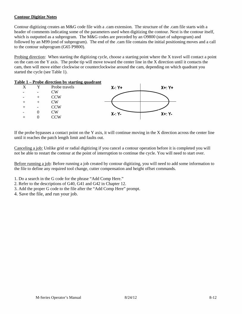
M-Series Operator’s Manual 8/24/12 8-12
Contour Digitize Notes Contour digitizing creates an M&G code file with a .cam extension. The structure of the .cam file starts with a header of comments indicating some of the parameters used when digitizing the contour. Next is the contour itself, which is outputted as a subprogram. The M&G codes are preceded by an O9800 (start of subprogram) and followed by an M99 (end of subprogram). The end of the .cam file contains the initial positioning moves and a call to the contour subprogram (G65 P9800). Probing direction: When starting the digitizing cycle, choose a starting point where the X travel will contact a point on the cam on the Y axis. The probe tip will move toward the center line in the X direction until it contacts the cam, then will move either clockwise or counterclockwise around the cam, depending on which quadrant you started the cycle (see Table 1). Table 1 – Probe direction by starting quadrant X Y Probe travels - - CW - + CCW + + CW + - CCW - 0 CW + 0 CCW
If the probe bypasses a contact point on the Y axis, it will continue moving in the X direction across the center line until it reaches the patch length limit and faults out.
Canceling a job: Unlike grid or radial digitizing if you cancel a contour operation before it is completed you will not be able to restart the contour at the point of interruption to continue the cycle. You will need to start over.
Before running a job: Before running a job created by contour digitizing, you will need to add some information to the file to define any required tool change, cutter compensation and height offset commands. 1. Do a search in the G code for the phrase “Add Comp Here.” 2. Refer to the descriptions of G40, G41 and G42 in Chapter 12. 3. Add the proper G code to the file after the “Add Comp Here” prompt. 4. Save the file, and run your job.
X-; Y+ X+; Y+
X-; Y- X+; Y-
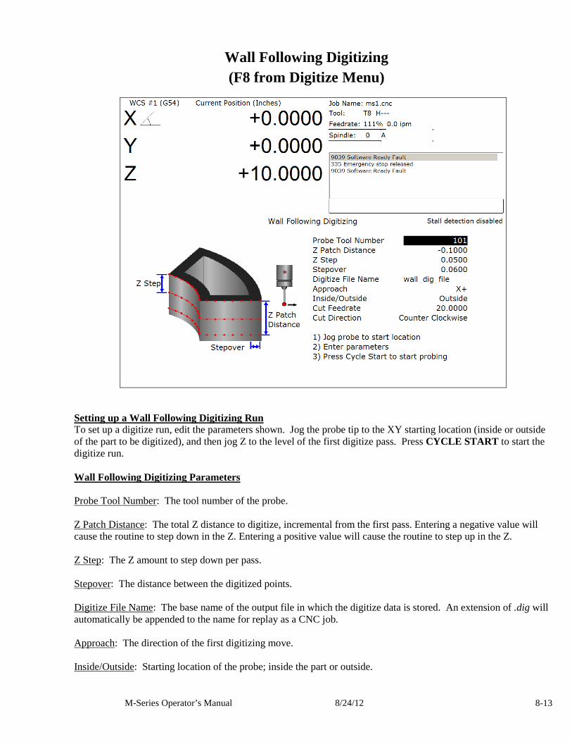
M-Series Operator’s Manual 8/24/12 8-13
Wall Following Digitizing (F8 from Digitize Menu)
Setting up a Wall Following Digitizing Run To set up a digitize run, edit the parameters shown. Jog the probe tip to the XY starting location (inside or outside of the part to be digitized), and then jog Z to the level of the first digitize pass. Press CYCLE START to start the digitize run. Wall Following Digitizing Parameters Probe Tool Number: The tool number of the probe. Z Patch Distance: The total Z distance to digitize, incremental from the first pass. Entering a negative value will cause the routine to step down in the Z. Entering a positive value will cause the routine to step up in the Z. Z Step: The Z amount to step down per pass. Stepover: The distance between the digitized points. Digitize File Name: The base name of the output file in which the digitize data is stored. An extension of .dig will automatically be appended to the name for replay as a CNC job. Approach: The direction of the first digitizing move. Inside/Outside: Starting location of the probe; inside the part or outside.

M-Series Operator’s Manual 8/24/12 8-14
Cut Feedrate: The replay feedrate. This is the feedrate that will be output to the file specified by the Digitize File Name above. This will cause the digitized data to be replayed at this specifed feedrate when the output data is run as a CNC job. Cut Direction: The Clockwise or Counter Clockwise direction of the output data. This also defines the direction of digitze. Wall Following Digitizing Notes The output data is uncompensated. Therefore the resultant output data points will be offset by the probe tip’s radius amount. If you want to run this data as a CNC job and actually do cutting, you must use a cutter that is the same shape and diameter as the probe tip. An alternative to this is to use a CAD/CAM software package to remove the probe tip offset and to apply the desired compensation.
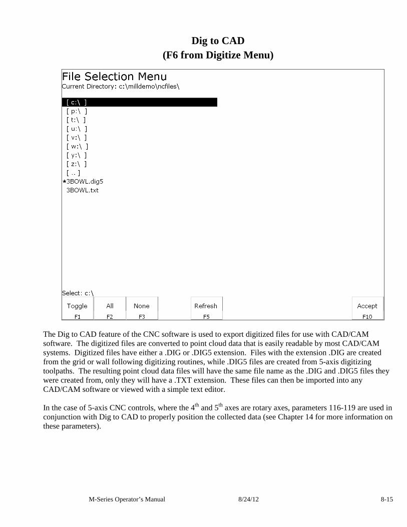
M-Series Operator’s Manual 8/24/12 8-15
Dig to CAD (F6 from Digitize Menu)
The Dig to CAD feature of the CNC software is used to export digitized files for use with CAD/CAM software. The digitized files are converted to point cloud data that is easily readable by most CAD/CAM systems. Digitized files have either a .DIG or .DIG5 extension. Files with the extension .DIG are created from the grid or wall following digitizing routines, while .DIG5 files are created from 5-axis digitizing toolpaths. The resulting point cloud data files will have the same file name as the .DIG and .DIG5 files they were created from, only they will have a .TXT extension. These files can then be imported into any CAD/CAM software or viewed with a simple text editor. In the case of 5-axis CNC controls, where the 4th and 5th axes are rotary axes, parameters 116-119 are used in conjunction with Dig to CAD to properly position the collected data (see Chapter 14 for more information on these parameters).
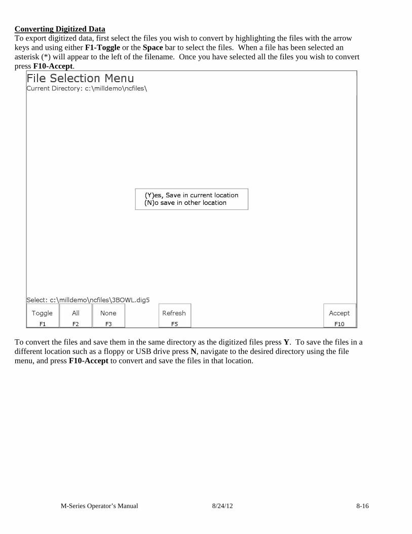
M-Series Operator’s Manual 8/24/12 8-16
Converting Digitized Data To export digitized data, first select the files you wish to convert by highlighting the files with the arrow keys and using either F1-Toggle or the Space bar to select the files. When a file has been selected an asterisk (*) will appear to the left of the filename. Once you have selected all the files you wish to convert press F10-Accept.
To convert the files and save them in the same directory as the digitized files press Y. To save the files in a different location such as a floppy or USB drive press N, navigate to the desired directory using the file menu, and press F10-Accept to convert and save the files in that location.
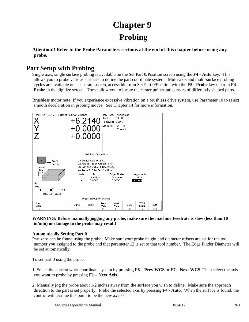
M-Series Operator’s Manual 8/24/12 9-1
Chapter 9 Probing
Attention!! Refer to the Probe Parameters sections at the end of this chapter before using any probe.
Part Setup with Probing Single axis, single surface probing is available on the Set Part 0/Position screen using the F4 - Auto key. This allows you to probe various surfaces to define the part coordinate system. Multi-axis and multi-surface probing cycles are available on a separate screen, accessible from Set Part 0/Position with the F5 - Probe key or from F4 - Probe in the digitize screen. These allow you to locate the center points and corners of differently shaped parts.
Brushless motor note: If you experience excessive vibration on a brushless drive system, use Parameter 10 to select smooth deceleration in probing moves. See Chapter 14 for more information.
WARNING: Before manually jogging any probe, make sure the machine Feedrate is slow (less than 10 in/min) or damage to the probe may result!
Automatically Setting Part 0 Part zero can be found using the probe. Make sure your probe height and diameter offsets are set for the tool number you assigned to the probe and that parameter 12 is set to that tool number. The Edge Finder Diameter will be set automatically.
To set part 0 using the probe: 1. Select the current work coordinate system by pressing F6 – Prev WCS or F7 – Next WCS. Then select the axis you want to probe by pressing F1 – Next Axis.
2. Manually jog the probe about 1/2 inches away from the surface you wish to define. Make sure the approach direction to the part is set properly. Probe the selected axis by pressing F4 - Auto. When the surface is found, the control will assume this point to be the new axis 0.
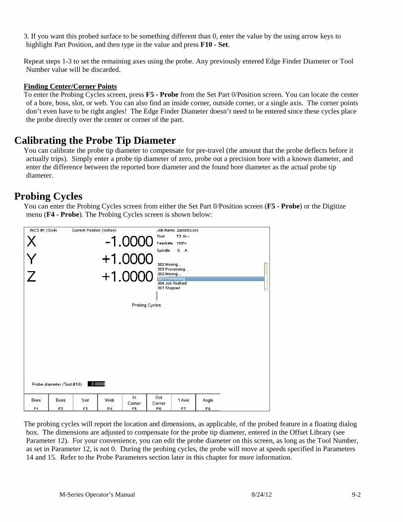
M-Series Operator’s Manual 8/24/12 9-2
3. If you want this probed surface to be something different than 0, enter the value by the using arrow keys to highlight Part Position, and then type in the value and press F10 - Set.
Repeat steps 1-3 to set the remaining axes using the probe. Any previously entered Edge Finder Diameter or Tool Number value will be discarded.
Finding Center/Corner Points To enter the Probing Cycles screen, press F5 - Probe from the Set Part 0/Position screen. You can locate the center of a bore, boss, slot, or web. You can also find an inside corner, outside corner, or a single axis. The corner points don’t even have to be right angles! The Edge Finder Diameter doesn’t need to be entered since these cycles place the probe directly over the center or corner of the part.
Calibrating the Probe Tip Diameter You can calibrate the probe tip diameter to compensate for pre-travel (the amount that the probe deflects before it actually trips). Simply enter a probe tip diameter of zero, probe out a precision bore with a known diameter, and enter the difference between the reported bore diameter and the found bore diameter as the actual probe tip diameter.
Probing Cycles You can enter the Probing Cycles screen from either the Set Part 0/Position screen (F5 - Probe) or the Digitize menu (F4 - Probe). The Probing Cycles screen is shown below:
The probing cycles will report the location and dimensions, as applicable, of the probed feature in a floating dialog box. The dimensions are adjusted to compensate for the probe tip diameter, entered in the Offset Library (see Parameter 12). For your convenience, you can edit the probe diameter on this screen, as long as the Tool Number, as set in Parameter 12, is not 0. During the probing cycles, the probe will move at speeds specified in Parameters 14 and 15. Refer to the Probe Parameters section later in this chapter for more information.
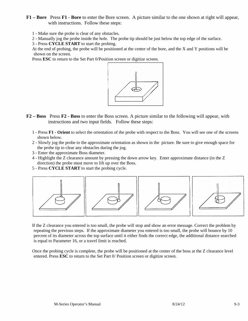
M-Series Operator’s Manual 8/24/12 9-3
F1 – Bore Press F1 - Bore to enter the Bore screen. A picture similar to the one shown at right will appear, with instructions. Follow these steps:
1 - Make sure the probe is clear of any obstacles. 2 - Manually jog the probe inside the hole. The probe tip should be just below the top edge of the surface. 3 - Press CYCLE START to start the probing. At the end of probing, the probe will be positioned at the center of the bore, and the X and Y positions will be shown on the screen.
Press ESC to return to the Set Part 0/Position screen or digitize screen.
F2 – Boss Press F2 - Boss to enter the Boss screen. A picture similar to the following will appear, with instructions and two input fields. Follow these steps:
1 - Press F1 - Orient to select the orientation of the probe with respect to the Boss. You will see one of the screens
shown below. 2 - Slowly jog the probe to the approximate orientation as shown in the picture. Be sure to give enough space for
the probe tip to clear any obstacles during the jog. 3 - Enter the approximate Boss diameter. 4 - Highlight the Z clearance amount by pressing the down arrow key. Enter approximate distance (in the Z
direction) the probe must move to lift up over the Boss. 5 - Press CYCLE START to start the probing cycle.
If the Z clearance you entered is too small, the probe will stop and show an error message. Correct the problem by repeating the previous steps. If the approximate diameter you entered is too small, the probe will bounce by 10 percent of its diameter across the top surface until it either finds the correct edge, the additional distance searched is equal to Parameter 16, or a travel limit is reached.
Once the probing cycle is complete, the probe will be positioned at the center of the boss at the Z clearance level entered. Press ESC to return to the Set Part 0/ Position screen or digitize screen.
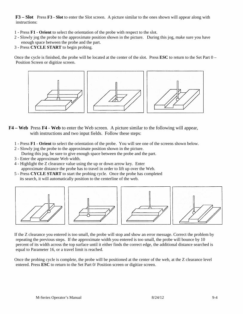
M-Series Operator’s Manual 8/24/12 9-4
F3 – Slot Press F3 - Slot to enter the Slot screen. A picture similar to the ones shown will appear along with instructions:
1 - Press F1 - Orient to select the orientation of the probe with respect to the slot. 2 - Slowly jog the probe to the approximate position shown in the picture. During this jog, make sure you have
enough space between the probe and the part. 3 - Press CYCLE START to begin probing. Once the cycle is finished, the probe will be located at the center of the slot. Press ESC to return to the Set Part 0 – Position Screen or digitize screen.
F4 – Web Press F4 - Web to enter the Web screen. A picture similar to the following will appear,
with instructions and two input fields. Follow these steps: 1 - Press F1 - Orient to select the orientation of the probe. You will see one of the screens shown below. 2 - Slowly jog the probe to the approximate position shown in the picture. During this jog, be sure to give enough space between the probe and the part.
3 - Enter the approximate Web width. 4 - Highlight the Z clearance value using the up or down arrow key. Enter approximate distance the probe has to travel in order to lift up over the Web.
5 - Press CYCLE START to start the probing cycle. Once the probe has completed its search, it will automatically position to the centerline of the web.
If the Z clearance you entered is too small, the probe will stop and show an error message. Correct the problem by repeating the previous steps. If the approximate width you entered is too small, the probe will bounce by 10 percent of its width across the top surface until it either finds the correct edge, the additional distance searched is equal to Parameter 16, or a travel limit is reached.
Once the probing cycle is complete, the probe will be positioned at the center of the web, at the Z clearance level entered. Press ESC to return to the Set Part 0/ Position screen or digitize screen.
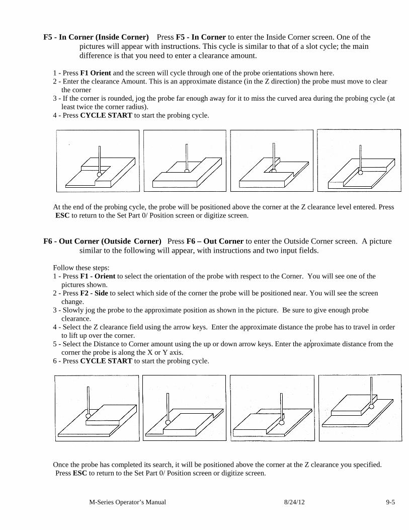
M-Series Operator’s Manual 8/24/12 9-5
F5 - In Corner (Inside Corner) Press F5 - In Corner to enter the Inside Corner screen. One of the
pictures will appear with instructions. This cycle is similar to that of a slot cycle; the main difference is that you need to enter a clearance amount.
1 - Press F1 Orient and the screen will cycle through one of the probe orientations shown here. 2 - Enter the clearance Amount. This is an approximate distance (in the Z direction) the probe must move to clear
the corner 3 - If the corner is rounded, jog the probe far enough away for it to miss the curved area during the probing cycle (at
least twice the corner radius). 4 - Press CYCLE START to start the probing cycle.
At the end of the probing cycle, the probe will be positioned above the corner at the Z clearance level entered. Press ESC to return to the Set Part 0/ Position screen or digitize screen.
F6 - Out Corner (Outside Corner) Press F6 – Out Corner to enter the Outside Corner screen. A picture similar to the following will appear, with instructions and two input fields.
Follow these steps: 1 - Press F1 - Orient to select the orientation of the probe with respect to the Corner. You will see one of the
pictures shown. 2 - Press F2 - Side to select which side of the corner the probe will be positioned near. You will see the screen
change. 3 - Slowly jog the probe to the approximate position as shown in the picture. Be sure to give enough probe
clearance. 4 - Select the Z clearance field using the arrow keys. Enter the approximate distance the probe has to travel in order
to lift up over the corner. 5 - Select the Distance to Corner amount using the up or down arrow keys. Enter the approximate distance from the
corner the probe is along the X or Y axis. 6 - Press CYCLE START to start the probing cycle.
Once the probe has completed its search, it will be positioned above the corner at the Z clearance you specified. Press ESC to return to the Set Part 0/ Position screen or digitize screen.
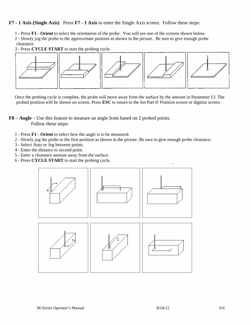
M-Series Operator’s Manual 8/24/12 9-6
F7 - 1 Axis (Single Axis) Press F7 - 1 Axis to enter the Single Axis screen. Follow these steps:
1 - Press F1 - Orient to select the orientation of the probe. You will see one of the screens shown below. 2 - Slowly jog the probe to the approximate position as shown in the picture. Be sure to give enough probe clearance.
3 - Press CYCLE START to start the probing cycle.
Once the probing cycle is complete, the probe will move away from the surface by the amount in Parameter 13. The probed position will be shown on screen. Press ESC to return to the Set Part 0/ Position screen or digitize screen.
F8 – Angle – Use this feature to measure an angle from based on 2 probed points. Follow these steps:
1 - Press F1 - Orient to select how the angle is to be measured. 2 - Slowly jog the probe to the first position as shown in the picture. Be sure to give enough probe clearance. 3 - Select Auto or Jog between points. 4 - Enter the distance to second point. 5 - Enter a clearance amount away from the surface. 6 - Press CYCLE START to start the probing cycle.
M-Series Operator’s Manual 8/24/12 9-7
Probe / TT-1 Parameters Various probing parameters can be set on the Machine Parameters screen (see Chapter 14). Make sure you enter these parameters before you begin using the probe and/or TT-1. If these parameters are not entered properly, damage to the probe or TT-1 may result.
Probe Type (Parameter 155) – This specifies the probe type being used. This needs to be set to 0 if you are using a standard Mechanical probe.
Probe PLC Input Number and Contact State (Parameter 11) - A single value, +/-1 through 240. A positive number indicates Closed on contact; a negative number indicates Open on contact.
TT1 PLC input number (Parameter 44) - This parameter is the input number that the TT1 is wired into on the PLC. If a shared PLC input is used for both the TT1 and the probe, then the value can be left at zero or set to the same value as parameter 11.
Probe Tool Number (Parameter 12) - A single value, 0 through 200, used to look up the length offset and tip diameter of the probe in the Offset Library.
Recovery Distance* (Parameter 13) – The additional distance the probe moves off of a surface after contact is broken, before attempting to traverse parallel to the surface.
Fast Probing Rate* (Parameter 14) - Used for positioning moves and initial surface detection, this parameter is determined by machine response and permitted probe deflection as well as desired tolerance. The default setting is 25 inches/min.
Slow Probing Rate* (Parameter 15) - Used for final measuring moves, this parameter is determined by a speed/accuracy tradeoff. The default setting is 3.5 inches/min.
Maximum Probing Distance (Parameter 16) - The maximum distance that a probing cycle "searches" for a surface in a given direction if no travel limits have been entered. The default is 10 inches. A larger value should be entered for the hole and slot cycles if you are measuring very large features.
Detector Location Return Point (Parameter 17) - A Zero (0) indicates that tool measurement will take place at the current position, a 1 or 2 indicates the number of the G30 reference point to use which specifies the X, Y location of the TT1 (WCS Configuration).
*Mechanical type probe only. Please see the DSP type probe section below for differences.
M-Series Operator’s Manual 8/24/12 9-8
DSP Probe Parameters When using a DSP type probe (such as DP-4D), a few of the probing parameters have a slightly different behavior than described above. These differences are noted below:
Probe Type (Parameter 155) – This specifies the probe type being used. This needs to be set to 1 for a DP-4D probe or set to 2 for a DP-7 probe.
Repeatability tolerance for probing and radial digitizing (Parameter 151) – used for DP-4 probes. Must be set to 0 for DSP probes.
Grid digitize prediction minimum Z pullback (Parameter 121) – set to 0.035 for DSP use. Recovery Distance (Parameter 13) – Works as described above but additionally it used as the distance to retract for a retry after a failed window (does not apply to M115/116/125/126 moves) (Default for DSP is 0.05). Note: If probing small bores this parameter may need to be reduced accordingly.
Fast Probing Rate (Parameter 14) – When using a DSP type probe, this is actually the rate at which the probe will move “in-between” actual probing moves. For instance, if you were probing a boss, this is the rate at which the probe will travel for the following moves:
1. When retracting from the surface after a point has been probed. 2. When retracting to the Z clearance position. 3. Rate at which it will traverse across the diameter of the boss at the Z clearance height. 4. Plunge rate to get to probing depth. Note: When measuring a TOOL with the TT1, the behavior is identical to that listed above. Slow Probing Rate (Parameter 15) – Used only when measuring a TOOL with the TT-1.
Additional Probe Parameters for DP-7 For the DP-7 probe (parameter 155 = 2), the following additional parameters are utilized: DP-7 Pullback Distance (Parameter 392) – This sets the distance the probe moves off from the surface after a probing move.
DP-7 Pullback Feedrate (Parameter 393) – This sets the feedrate for the pullback move. DP-7 Measuring Feedrate (Parameter 394) – This sets the feedrate for the slow measuring move.
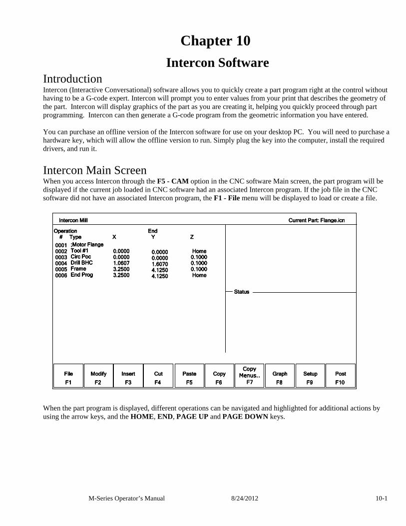
M-Series Operator’s Manual 8/24/2012 10-1
Chapter 10 Intercon Software
Introduction Intercon (Interactive Conversational) software allows you to quickly create a part program right at the control without having to be a G-code expert. Intercon will prompt you to enter values from your print that describes the geometry of the part. Intercon will display graphics of the part as you are creating it, helping you quickly proceed through part programming. Intercon can then generate a G-code program from the geometric information you have entered. You can purchase an offline version of the Intercon software for use on your desktop PC. You will need to purchase a hardware key, which will allow the offline version to run. Simply plug the key into the computer, install the required drivers, and run it.
Intercon Main Screen When you access Intercon through the F5 - CAM option in the CNC software Main screen, the part program will be displayed if the current job loaded in CNC software had an associated Intercon program. If the job file in the CNC software did not have an associated Intercon program, the F1 - File menu will be displayed to load or create a file. When the part program is displayed, different operations can be navigated and highlighted for additional actions by using the arrow keys, and the HOME , END, PAGE UP and PAGE DOWN keys.
Intercon Mill Intercon Mill Intercon Mill Intercon Mill Current Part: Flange.icn Current Part: Flange.icn Current Part: Flange.icn Current Part: Flange.icn
FileFileFileFile
FFFF1111
ModifyModifyModifyModify
FFFF2222
CopyCopyCopyCopy
Menus..Menus..Menus..Menus..
FFFF7777
PastePastePastePaste
FFFF5555
InsertInsertInsertInsert
FFFF3333
CutCutCutCut
FFFF4444
CopyCopyCopyCopy
FFFF6666
GraphGraphGraphGraph
FFFF8888
PostPostPostPost
FFFF10101010
SetupSetupSetupSetup
FFFF9999
;Motor Flange;Motor Flange;Motor Flange;Motor Flange Tool #1Tool #1Tool #1Tool #1 Circ PocCirc PocCirc PocCirc Poc Drill BHCDrill BHCDrill BHCDrill BHC FrameFrameFrameFrame End ProgEnd ProgEnd ProgEnd Prog
Home Home Home Home 0.10000.10000.10000.1000 0.10000.10000.10000.1000 0.10000.10000.10000.1000 Home Home Home Home
0.00000.00000.00000.0000 0.00000.00000.00000.0000 1.60701.60701.60701.6070 4.12504.12504.12504.1250 4.12504.12504.12504.1250
0.00000.00000.00000.0000 0.00000.00000.00000.0000 1.06071.06071.06071.0607 3.25003.25003.25003.2500 3.25003.25003.25003.2500
0001000100010001 0002000200020002 0003000300030003 0004000400040004 0005000500050005 0006000600060006
Operation End Operation End Operation End Operation End # Type X Y Z # Type X Y Z # Type X Y Z # Type X Y Z
StatusStatusStatusStatus
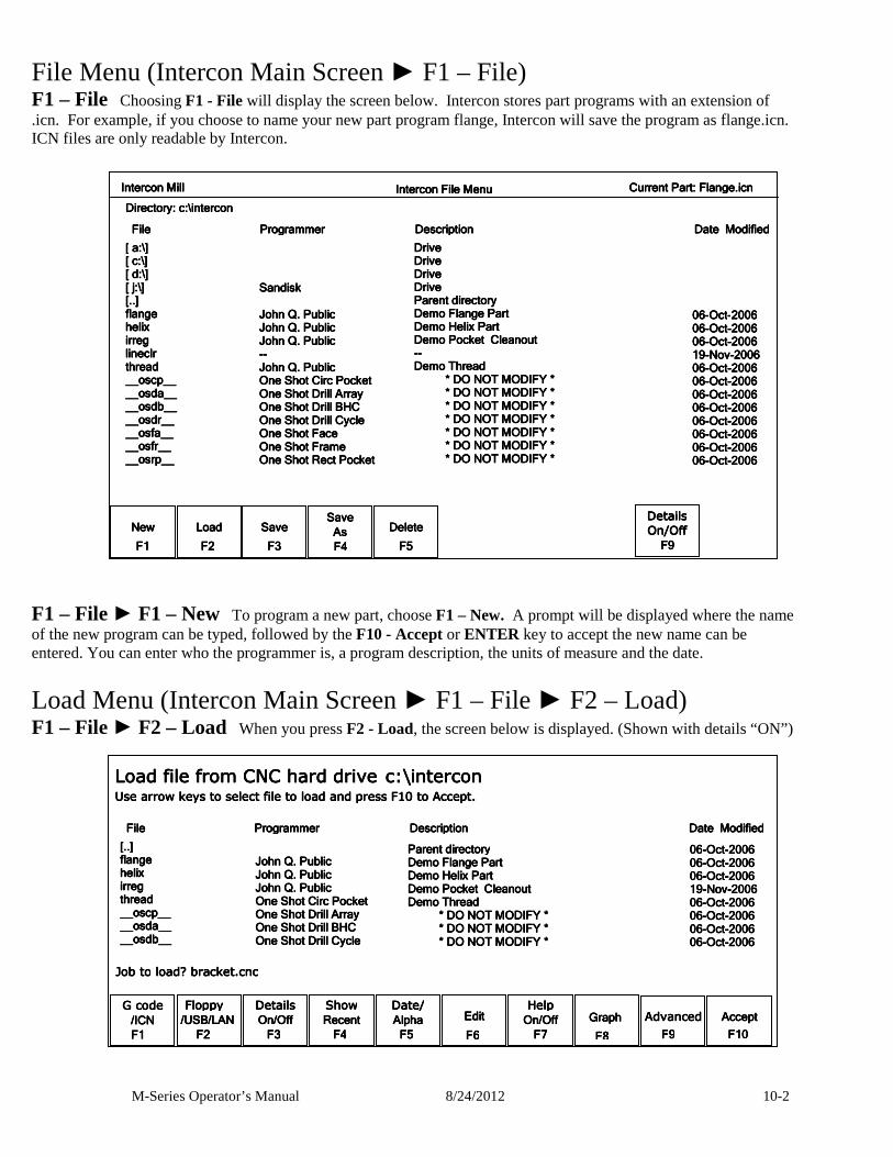
M-Series Operator’s Manual 8/24/2012 10-2
File Menu (Intercon Main Screen ► F1 – File) F1 – File Choosing F1 - File will display the screen below. Intercon stores part programs with an extension of .icn. For example, if you choose to name your new part program flange, Intercon will save the program as flange.icn. ICN files are only readable by Intercon.
F1 – File ► F1 – New To program a new part, choose F1 – New. A prompt will be displayed where the name of the new program can be typed, followed by the F10 - Accept or ENTER key to accept the new name can be entered. You can enter who the programmer is, a program description, the units of measure and the date.
Load Menu (Intercon Main Screen ► F1 – File ► F2 – Load) F1 – File ► F2 – Load When you press F2 - Load, the screen below is displayed. (Shown with details “ON”)
Intercon Mill Intercon Mill Intercon Mill Intercon Mill Current Part: Flange.icn Current Part: Flange.icn Current Part: Flange.icn Current Part: Flange.icn
NewNewNewNew
FFFF1111
LoadLoadLoadLoad
FFFF2222
DeleteDeleteDeleteDelete
FFFF5555
SaveSaveSaveSave
FFFF3333
Save Save Save Save
As As As As
F4 F4 F4 F4
DetailsDetailsDetailsDetails
On/OffOn/OffOn/OffOn/Off
FFFF9999
Intercon File Menu Intercon File Menu Intercon File Menu Intercon File Menu
[[[[ a: a: a: a:\\\\]]]] [ c:[ c:[ c:[ c:\\\\]]]] [ d:[ d:[ d:[ d:\\\\]]]] [ j:[ j:[ j:[ j:\\\\]]]] [..][..][..][..] flangeflangeflangeflange helixhelixhelixhelix irregirregirregirreg lineclrlineclrlineclrlineclr threadthreadthreadthread __oscp____oscp____oscp____oscp__ __osda____osda____osda____osda__ __osdb____osdb____osdb____osdb__ __osdr____osdr____osdr____osdr__ __osfa____osfa____osfa____osfa__ __osfr____osfr____osfr____osfr__ __osrp____osrp____osrp____osrp__
DriveDriveDriveDrive DriveDriveDriveDrive DriveDriveDriveDrive DriveDriveDriveDrive Parent directoryParent directoryParent directoryParent directory Demo Flange PartDemo Flange PartDemo Flange PartDemo Flange Part Demo Helix PartDemo Helix PartDemo Helix PartDemo Helix Part Demo Pocket CleanoutDemo Pocket CleanoutDemo Pocket CleanoutDemo Pocket Cleanout -------- Demo ThreadDemo ThreadDemo ThreadDemo Thread * D * D * D * DO NOT MODIFY *O NOT MODIFY *O NOT MODIFY *O NOT MODIFY * * DO NOT MODIFY * * DO NOT MODIFY * * DO NOT MODIFY * * DO NOT MODIFY * * DO NOT MODIFY * * DO NOT MODIFY * * DO NOT MODIFY * * DO NOT MODIFY * * DO NOT MODIFY * * DO NOT MODIFY * * DO NOT MODIFY * * DO NOT MODIFY * * DO NOT MODIFY * * DO NOT MODIFY * * DO NOT MODIFY * * DO NOT MODIFY * * DO NOT MODIFY * * DO NOT MODIFY * * DO NOT MODIFY * * DO NOT MODIFY * * DO NOT MODIFY * * DO NOT MODIFY * * DO NOT MODIFY * * DO NOT MODIFY *
SandiskSandiskSandiskSandisk
File Programmer File Programmer File Programmer File Programmer Description Date Modified Description Date Modified Description Date Modified Description Date Modified
John Q. PublicJohn Q. PublicJohn Q. PublicJohn Q. Public John Q. PublicJohn Q. PublicJohn Q. PublicJohn Q. Public John Q. PublicJohn Q. PublicJohn Q. PublicJohn Q. Public -------- John Q. PublicJohn Q. PublicJohn Q. PublicJohn Q. Public One Shot Circ PocketOne Shot Circ PocketOne Shot Circ PocketOne Shot Circ Pocket One Shot Drill ArrayOne Shot Drill ArrayOne Shot Drill ArrayOne Shot Drill Array One Shot Drill BHCOne Shot Drill BHCOne Shot Drill BHCOne Shot Drill BHC One Shot DrillOne Shot DrillOne Shot DrillOne Shot Drill Cycle Cycle Cycle Cycle One Shot FaceOne Shot FaceOne Shot FaceOne Shot Face One Shot FrameOne Shot FrameOne Shot FrameOne Shot Frame One Shot Rect PocketOne Shot Rect PocketOne Shot Rect PocketOne Shot Rect Pocket
06060606----OctOctOctOct----2006200620062006 06060606----OctOctOctOct----2006200620062006 06060606----OctOctOctOct----2006200620062006 19191919----NovNovNovNov----2006200620062006 06060606----OctOctOctOct----2006200620062006 06060606----OctOctOctOct----2006200620062006 06060606----OctOctOctOct----2006200620062006 06060606----OctOctOctOct----2006200620062006 06060606----OctOctOctOct----2006200620062006 06060606----OctOctOctOct----2006200620062006 06060606----OctOctOctOct----2006200620062006 06060606----OctOctOctOct----2006200620062006
Directory: c:Directory: c:Directory: c:Directory: c:\\\\intercon intercon intercon intercon
Floppy Floppy Floppy Floppy
////USB/LANUSB/LANUSB/LANUSB/LAN
FFFF2222
DetailsDetailsDetailsDetails
On/OffOn/OffOn/OffOn/Off
FFFF3333
ShowShowShowShow
RecentRecentRecentRecent
FFFF4444
Date/Date/Date/Date/
AlphaAlphaAlphaAlpha
FFFF5555
EditEditEditEdit
FFFF6666
HelpHelpHelpHelp
OnOnOnOn////OffOffOffOff
FFFF7777
Graph Graph Graph Graph
FFFF8888
AdvancedAdvancedAdvancedAdvanced
FFFF9999
AcceptAcceptAcceptAccept
F1F1F1F10000
G code G code G code G code
/ICN/ICN/ICN/ICN
F1F1F1F1
Load file from CNC hLoad file from CNC hLoad file from CNC hLoad file from CNC hard driveard driveard driveard drive c:c:c:c:\\\\interconinterconinterconintercon Use arrow keys to select file to load and press F10 to Accept.Use arrow keys to select file to load and press F10 to Accept.Use arrow keys to select file to load and press F10 to Accept.Use arrow keys to select file to load and press F10 to Accept.
Job Job Job Job totototo load? bracket.cnc load? bracket.cnc load? bracket.cnc load? bracket.cnc
[..][..][..][..] flangeflangeflangeflange helixhelixhelixhelix irregirregirregirreg threadthreadthreadthread __oscp____oscp____oscp____oscp__ __osda____osda____osda____osda__ __osdb____osdb____osdb____osdb__
Parent directoryParent directoryParent directoryParent directory Demo Flange PartDemo Flange PartDemo Flange PartDemo Flange Part Demo Helix PartDemo Helix PartDemo Helix PartDemo Helix Part Demo Pocket CleanoutDemo Pocket CleanoutDemo Pocket CleanoutDemo Pocket Cleanout Demo ThreadDemo ThreadDemo ThreadDemo Thread * DO NOT MODIFY * * DO NOT MODIFY * * DO NOT MODIFY * * DO NOT MODIFY * * DO NOT MODIFY * * DO NOT MODIFY * * DO NOT MODIFY * * DO NOT MODIFY * * DO NOT MODIFY * * DO NOT MODIFY * * DO NOT MODIFY * * DO NOT MODIFY *
File Programmer Description Date M File Programmer Description Date M File Programmer Description Date M File Programmer Description Date Modifiedodifiedodifiedodified
John Q. PublicJohn Q. PublicJohn Q. PublicJohn Q. Public John Q. PublicJohn Q. PublicJohn Q. PublicJohn Q. Public John Q. PublicJohn Q. PublicJohn Q. PublicJohn Q. Public One Shot Circ PocketOne Shot Circ PocketOne Shot Circ PocketOne Shot Circ Pocket One Shot Drill ArrayOne Shot Drill ArrayOne Shot Drill ArrayOne Shot Drill Array One Shot Drill BHCOne Shot Drill BHCOne Shot Drill BHCOne Shot Drill BHC One Shot Drill CycleOne Shot Drill CycleOne Shot Drill CycleOne Shot Drill Cycle
06060606----OctOctOctOct----2006200620062006 06060606----OctOctOctOct----2006200620062006 06060606----OctOctOctOct----2006200620062006 19191919----NovNovNovNov----2006200620062006 06060606----OctOctOctOct----2006200620062006 06060606----OctOctOctOct----2006200620062006 06060606----OctOctOctOct----2006200620062006 06060606----OctOctOctOct----2006200620062006
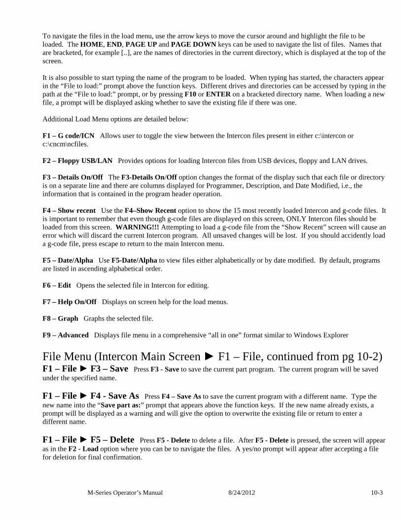
M-Series Operator’s Manual 8/24/2012 10-3
To navigate the files in the load menu, use the arrow keys to move the cursor around and highlight the file to be loaded. The HOME , END, PAGE UP and PAGE DOWN keys can be used to navigate the list of files. Names that are bracketed, for example [..], are the names of directories in the current directory, which is displayed at the top of the screen. It is also possible to start typing the name of the program to be loaded. When typing has started, the characters appear in the “File to load:” prompt above the function keys. Different drives and directories can be accessed by typing in the path at the “File to load:” prompt, or by pressing F10 or ENTER on a bracketed directory name. When loading a new file, a prompt will be displayed asking whether to save the existing file if there was one. Additional Load Menu options are detailed below: F1 – G code/ICN Allows user to toggle the view between the Intercon files present in either c:\intercon or c:\cncm\ncfiles. F2 – Floppy USB/LAN Provides options for loading Intercon files from USB devices, floppy and LAN drives. F3 – Details On/Off The F3-Details On/Off option changes the format of the display such that each file or directory is on a separate line and there are columns displayed for Programmer, Description, and Date Modified, i.e., the information that is contained in the program header operation. F4 – Show recent Use the F4–Show Recent option to show the 15 most recently loaded Intercon and g-code files. It is important to remember that even though g-code files are displayed on this screen, ONLY Intercon files should be loaded from this screen. WARNING!!! Attempting to load a g-code file from the “Show Recent” screen will cause an error which will discard the current Intercon program. All unsaved changes will be lost. If you should accidently load a g-code file, press escape to return to the main Intercon menu. F5 – Date/Alpha Use F5-Date/Alpha to view files either alphabetically or by date modified. By default, programs are listed in ascending alphabetical order. F6 – Edit Opens the selected file in Intercon for editing. F7 – Help On/Off Displays on screen help for the load menus. F8 – Graph Graphs the selected file. F9 – Advanced Displays file menu in a comprehensive “all in one” format similar to Windows Explorer
File Menu (Intercon Main Screen ► F1 – File, continued from pg 10-2) F1 – File ► F3 – Save Press F3 - Save to save the current part program. The current program will be saved under the specified name.
F1 – File ► F4 - Save As Press F4 – Save As to save the current program with a different name. Type the new name into the “Save part as:” prompt that appears above the function keys. If the new name already exists, a prompt will be displayed as a warning and will give the option to overwrite the existing file or return to enter a different name.
F1 – File ► F5 – Delete Press F5 - Delete to delete a file. After F5 - Delete is pressed, the screen will appear as in the F2 - Load option where you can be to navigate the files. A yes/no prompt will appear after accepting a file for deletion for final confirmation.
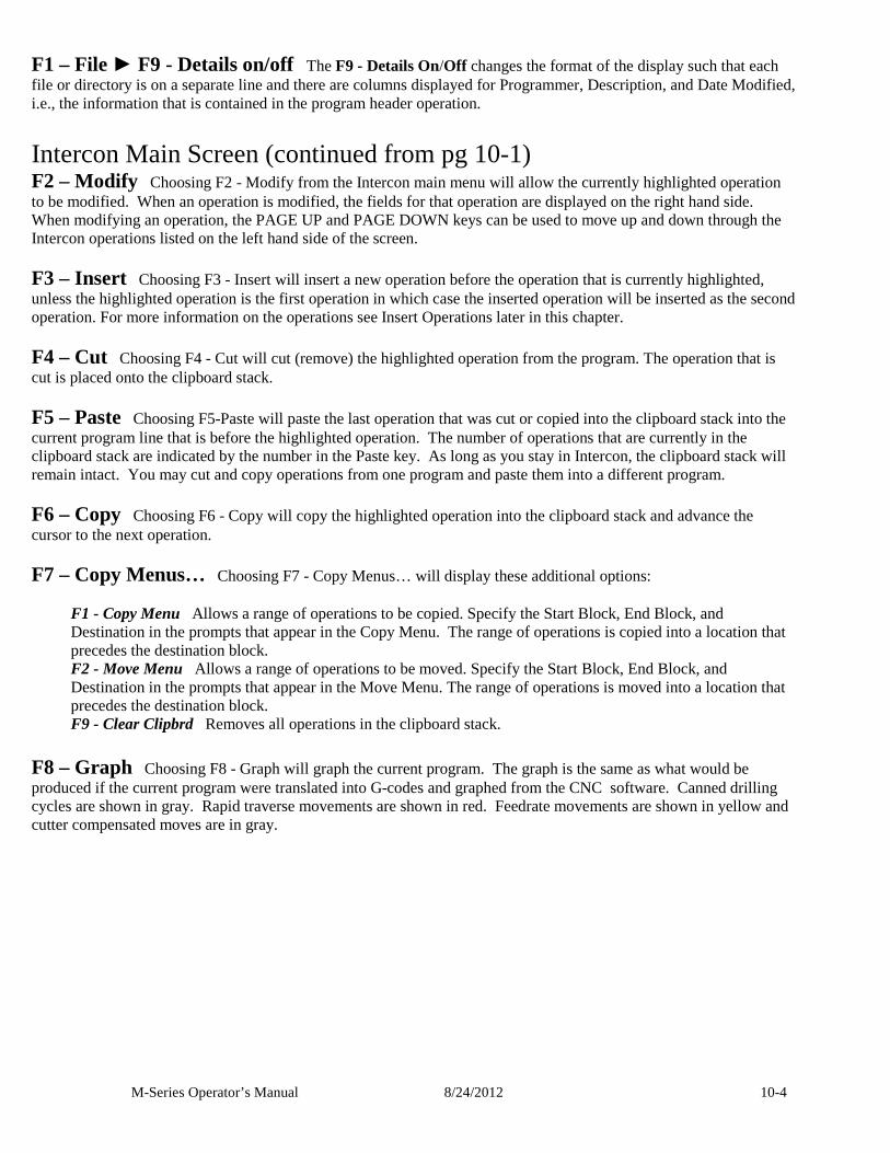
M-Series Operator’s Manual 8/24/2012 10-4
F1 – File ► F9 - Details on/off The F9 - Details On/Off changes the format of the display such that each file or directory is on a separate line and there are columns displayed for Programmer, Description, and Date Modified, i.e., the information that is contained in the program header operation.
Intercon Main Screen (continued from pg 10-1) F2 – Modify Choosing F2 - Modify from the Intercon main menu will allow the currently highlighted operation to be modified. When an operation is modified, the fields for that operation are displayed on the right hand side. When modifying an operation, the PAGE UP and PAGE DOWN keys can be used to move up and down through the Intercon operations listed on the left hand side of the screen.
F3 – Insert Choosing F3 - Insert will insert a new operation before the operation that is currently highlighted, unless the highlighted operation is the first operation in which case the inserted operation will be inserted as the second operation. For more information on the operations see Insert Operations later in this chapter.
F4 – Cut Choosing F4 - Cut will cut (remove) the highlighted operation from the program. The operation that is cut is placed onto the clipboard stack.
F5 – Paste Choosing F5-Paste will paste the last operation that was cut or copied into the clipboard stack into the current program line that is before the highlighted operation. The number of operations that are currently in the clipboard stack are indicated by the number in the Paste key. As long as you stay in Intercon, the clipboard stack will remain intact. You may cut and copy operations from one program and paste them into a different program.
F6 – Copy Choosing F6 - Copy will copy the highlighted operation into the clipboard stack and advance the cursor to the next operation.
F7 – Copy Menus… Choosing F7 - Copy Menus… will display these additional options:
F1 - Copy Menu Allows a range of operations to be copied. Specify the Start Block, End Block, and Destination in the prompts that appear in the Copy Menu. The range of operations is copied into a location that precedes the destination block. F2 - Move Menu Allows a range of operations to be moved. Specify the Start Block, End Block, and Destination in the prompts that appear in the Move Menu. The range of operations is moved into a location that precedes the destination block. F9 - Clear Clipbrd Removes all operations in the clipboard stack.
F8 – Graph Choosing F8 - Graph will graph the current program. The graph is the same as what would be produced if the current program were translated into G-codes and graphed from the CNC software. Canned drilling cycles are shown in gray. Rapid traverse movements are shown in red. Feedrate movements are shown in yellow and cutter compensated moves are in gray.
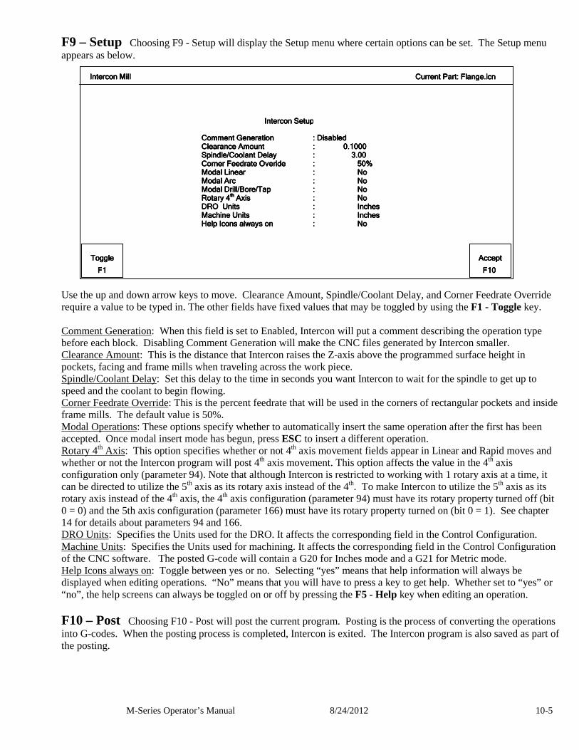
M-Series Operator’s Manual 8/24/2012 10-5
F9 – Setup Choosing F9 - Setup will display the Setup menu where certain options can be set. The Setup menu appears as below. Use the up and down arrow keys to move. Clearance Amount, Spindle/Coolant Delay, and Corner Feedrate Override require a value to be typed in. The other fields have fixed values that may be toggled by using the F1 - Toggle key. Comment Generation: When this field is set to Enabled, Intercon will put a comment describing the operation type before each block. Disabling Comment Generation will make the CNC files generated by Intercon smaller. Clearance Amount: This is the distance that Intercon raises the Z-axis above the programmed surface height in pockets, facing and frame mills when traveling across the work piece. Spindle/Coolant Delay: Set this delay to the time in seconds you want Intercon to wait for the spindle to get up to speed and the coolant to begin flowing. Corner Feedrate Override: This is the percent feedrate that will be used in the corners of rectangular pockets and inside frame mills. The default value is 50%. Modal Operations: These options specify whether to automatically insert the same operation after the first has been accepted. Once modal insert mode has begun, press ESC to insert a different operation. Rotary 4th Axis: This option specifies whether or not 4th axis movement fields appear in Linear and Rapid moves and whether or not the Intercon program will post 4th axis movement. This option affects the value in the 4th axis configuration only (parameter 94). Note that although Intercon is restricted to working with 1 rotary axis at a time, it can be directed to utilize the 5th axis as its rotary axis instead of the 4th. To make Intercon to utilize the 5th axis as its rotary axis instead of the 4th axis, the 4th axis configuration (parameter 94) must have its rotary property turned off (bit 0 = 0) and the 5th axis configuration (parameter 166) must have its rotary property turned on (bit 0 = 1). See chapter 14 for details about parameters 94 and 166. DRO Units: Specifies the Units used for the DRO. It affects the corresponding field in the Control Configuration. Machine Units: Specifies the Units used for machining. It affects the corresponding field in the Control Configuration of the CNC software. The posted G-code will contain a G20 for Inches mode and a G21 for Metric mode. Help Icons always on: Toggle between yes or no. Selecting “yes” means that help information will always be displayed when editing operations. “No” means that you will have to press a key to get help. Whether set to “yes” or “no”, the help screens can always be toggled on or off by pressing the F5 - Help key when editing an operation.
F10 – Post Choosing F10 - Post will post the current program. Posting is the process of converting the operations into G-codes. When the posting process is completed, Intercon is exited. The Intercon program is also saved as part of the posting.
Intercon Mill Intercon Mill Intercon Mill Intercon Mill Current Part: Flange.icn Current Part: Flange.icn Current Part: Flange.icn Current Part: Flange.icn
ToToToToggleggleggleggle
FFFF1111
AcceptAcceptAcceptAccept
FFFF10101010
: Disabled : Disabled : Disabled : Disabled : 0.1000: 0.1000: 0.1000: 0.1000 : 3.00: 3.00: 3.00: 3.00 : 50%: 50%: 50%: 50% : No: No: No: No : No: No: No: No : No : No : No : No : No : No : No : No : Inches: Inches: Inches: Inches : : : : Inches Inches Inches Inches : No: No: No: No
Comment GenerationComment GenerationComment GenerationComment Generation Clearance AmountClearance AmountClearance AmountClearance Amount Spindle/Coolant DelaySpindle/Coolant DelaySpindle/Coolant DelaySpindle/Coolant Delay Corner Feedrate OverideCorner Feedrate OverideCorner Feedrate OverideCorner Feedrate Overide Modal LinearModal LinearModal LinearModal Linear Modal ArcModal ArcModal ArcModal Arc Modal Drill/Bore/TapModal Drill/Bore/TapModal Drill/Bore/TapModal Drill/Bore/Tap Rotary 4Rotary 4Rotary 4Rotary 4
thththth Axis Axis Axis Axis DRO UnitsDRO UnitsDRO UnitsDRO Units Machine UnitsMachine UnitsMachine UnitsMachine Units Help Icons always onHelp Icons always onHelp Icons always onHelp Icons always on
Intercon Setup Intercon Setup Intercon Setup Intercon Setup
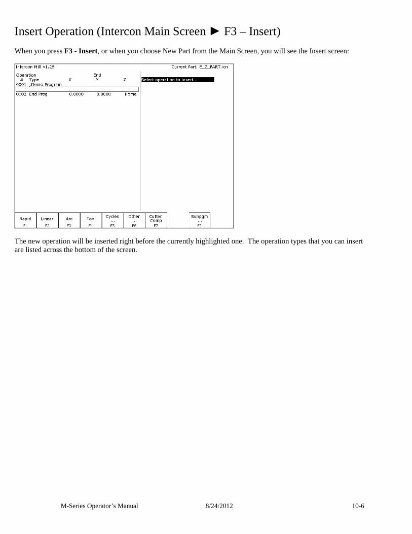
M-Series Operator’s Manual 8/24/2012 10-6
Insert Operation (Intercon Main Screen ► F3 – Insert) When you press F3 - Insert, or when you choose New Part from the Main Screen, you will see the Insert screen:
The new operation will be inserted right before the currently highlighted one. The operation types that you can insert are listed across the bottom of the screen.
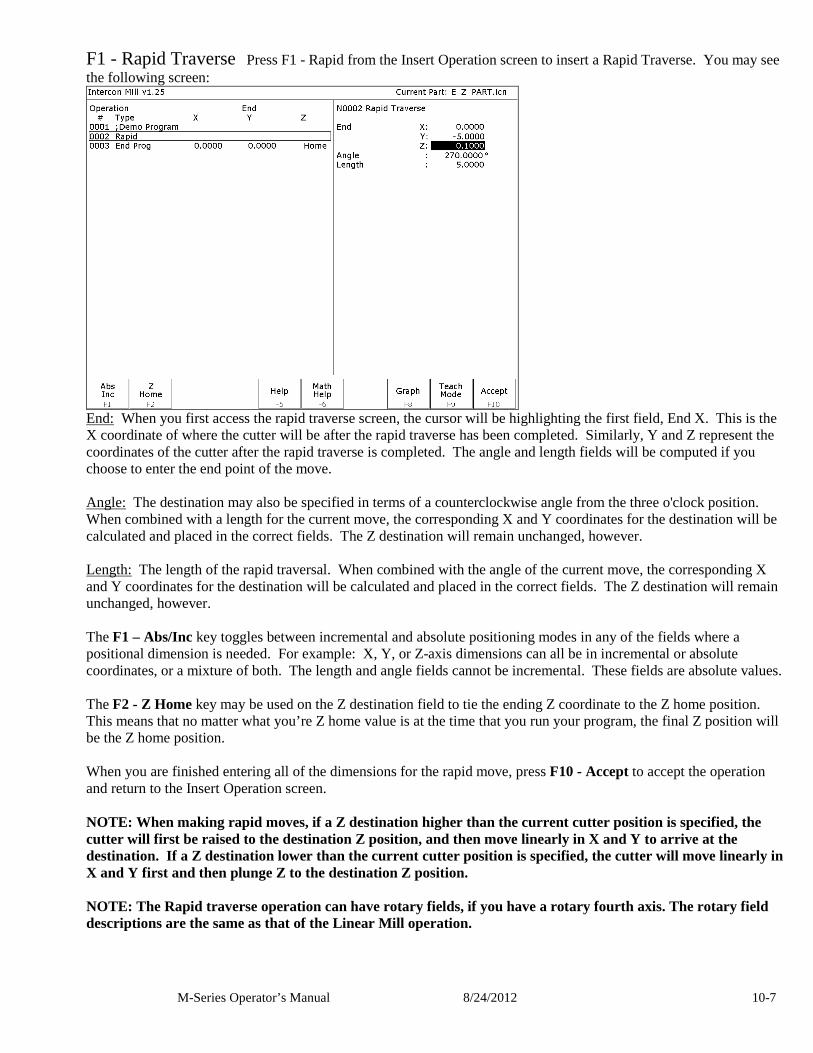
M-Series Operator’s Manual 8/24/2012 10-7
F1 - Rapid Traverse Press F1 - Rapid from the Insert Operation screen to insert a Rapid Traverse. You may see the following screen:
End: When you first access the rapid traverse screen, the cursor will be highlighting the first field, End X. This is the X coordinate of where the cutter will be after the rapid traverse has been completed. Similarly, Y and Z represent the coordinates of the cutter after the rapid traverse is completed. The angle and length fields will be computed if you choose to enter the end point of the move. Angle: The destination may also be specified in terms of a counterclockwise angle from the three o'clock position. When combined with a length for the current move, the corresponding X and Y coordinates for the destination will be calculated and placed in the correct fields. The Z destination will remain unchanged, however. Length: The length of the rapid traversal. When combined with the angle of the current move, the corresponding X and Y coordinates for the destination will be calculated and placed in the correct fields. The Z destination will remain unchanged, however. The F1 – Abs/Inc key toggles between incremental and absolute positioning modes in any of the fields where a positional dimension is needed. For example: X, Y, or Z-axis dimensions can all be in incremental or absolute coordinates, or a mixture of both. The length and angle fields cannot be incremental. These fields are absolute values. The F2 - Z Home key may be used on the Z destination field to tie the ending Z coordinate to the Z home position. This means that no matter what you’re Z home value is at the time that you run your program, the final Z position will be the Z home position. When you are finished entering all of the dimensions for the rapid move, press F10 - Accept to accept the operation and return to the Insert Operation screen. NOTE: When making rapid moves, if a Z destination higher than the current cutter position is specified, the cutter will first be raised to the destination Z position, and then move linearly in X and Y to arrive at the destination. If a Z destination lower than the current cutter position is specified, the cutter will move linearly in X and Y first and then plunge Z to the destination Z position. NOTE: The Rapid traverse operation can have rotary fields, if you have a rotary fourth axis. The rotary field descriptions are the same as that of the Linear Mill operation.
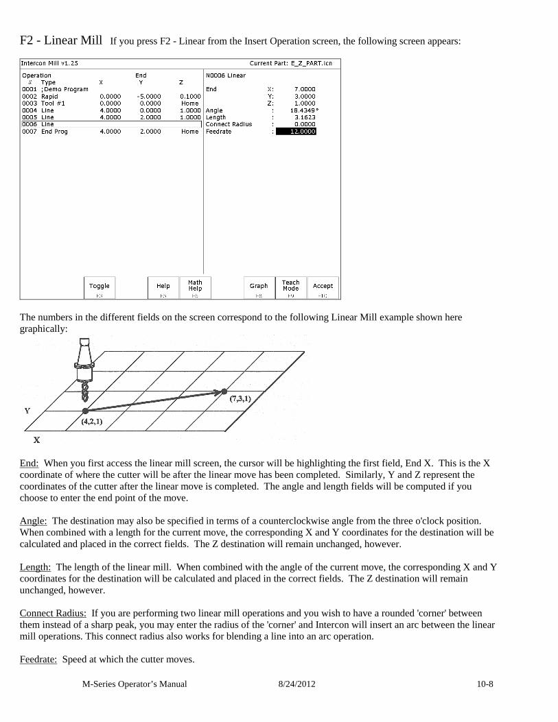
M-Series Operator’s Manual 8/24/2012 10-8
F2 - Linear Mill If you press F2 - Linear from the Insert Operation screen, the following screen appears:
The numbers in the different fields on the screen correspond to the following Linear Mill example shown here graphically:
End: When you first access the linear mill screen, the cursor will be highlighting the first field, End X. This is the X coordinate of where the cutter will be after the linear move has been completed. Similarly, Y and Z represent the coordinates of the cutter after the linear move is completed. The angle and length fields will be computed if you choose to enter the end point of the move. Angle: The destination may also be specified in terms of a counterclockwise angle from the three o'clock position. When combined with a length for the current move, the corresponding X and Y coordinates for the destination will be calculated and placed in the correct fields. The Z destination will remain unchanged, however. Length: The length of the linear mill. When combined with the angle of the current move, the corresponding X and Y coordinates for the destination will be calculated and placed in the correct fields. The Z destination will remain unchanged, however. Connect Radius: If you are performing two linear mill operations and you wish to have a rounded 'corner' between them instead of a sharp peak, you may enter the radius of the 'corner' and Intercon will insert an arc between the linear mill operations. This connect radius also works for blending a line into an arc operation. Feedrate: Speed at which the cutter moves.
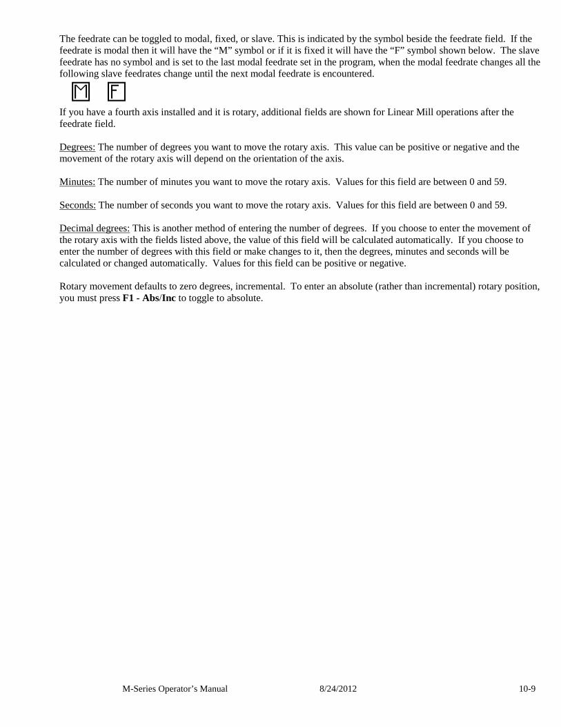
M-Series Operator’s Manual 8/24/2012 10-9
The feedrate can be toggled to modal, fixed, or slave. This is indicated by the symbol beside the feedrate field. If the feedrate is modal then it will have the “M” symbol or if it is fixed it will have the “F” symbol shown below. The slave feedrate has no symbol and is set to the last modal feedrate set in the program, when the modal feedrate changes all the following slave feedrates change until the next modal feedrate is encountered.
If you have a fourth axis installed and it is rotary, additional fields are shown for Linear Mill operations after the feedrate field. Degrees: The number of degrees you want to move the rotary axis. This value can be positive or negative and the movement of the rotary axis will depend on the orientation of the axis. Minutes: The number of minutes you want to move the rotary axis. Values for this field are between 0 and 59. Seconds: The number of seconds you want to move the rotary axis. Values for this field are between 0 and 59. Decimal degrees: This is another method of entering the number of degrees. If you choose to enter the movement of the rotary axis with the fields listed above, the value of this field will be calculated automatically. If you choose to enter the number of degrees with this field or make changes to it, then the degrees, minutes and seconds will be calculated or changed automatically. Values for this field can be positive or negative. Rotary movement defaults to zero degrees, incremental. To enter an absolute (rather than incremental) rotary position, you must press F1 - Abs/Inc to toggle to absolute.
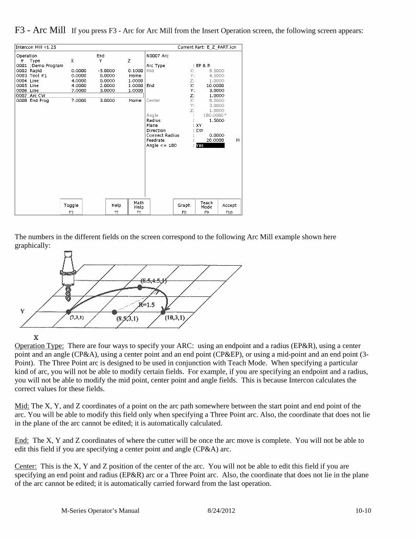
M-Series Operator’s Manual 8/24/2012 10-10
F3 - Arc Mill If you press F3 - Arc for Arc Mill from the Insert Operation screen, the following screen appears:
The numbers in the different fields on the screen correspond to the following Arc Mill example shown here graphically:
Operation Type: There are four ways to specify your ARC: using an endpoint and a radius (EP&R), using a center point and an angle (CP&A), using a center point and an end point (CP&EP), or using a mid-point and an end point (3-Point). The Three Point arc is designed to be used in conjunction with Teach Mode. When specifying a particular kind of arc, you will not be able to modify certain fields. For example, if you are specifying an endpoint and a radius, you will not be able to modify the mid point, center point and angle fields. This is because Intercon calculates the correct values for these fields. Mid: The X, Y, and Z coordinates of a point on the arc path somewhere between the start point and end point of the arc. You will be able to modify this field only when specifying a Three Point arc. Also, the coordinate that does not lie in the plane of the arc cannot be edited; it is automatically calculated. End: The X, Y and Z coordinates of where the cutter will be once the arc move is complete. You will not be able to edit this field if you are specifying a center point and angle (CP&A) arc. Center: This is the X, Y and Z position of the center of the arc. You will not be able to edit this field if you are specifying an end point and radius (EP&R) arc or a Three Point arc. Also, the coordinate that does not lie in the plane of the arc cannot be edited; it is automatically carried forward from the last operation.
M-Series Operator’s Manual 8/24/2012 10-11
Angle: Number of degrees through which the cutter will travel. This value must lie between 0 and 360 degrees. You will be able to edit this field only if you are specifying a center point and angle (CP&A) arc. Radius: Distance from the center of the arc to its edge. This value must be greater than 0. You will only be able to edit this value if you are specifying an end point and radius (EP&R) arc. Plane: This determines whether the arc is to be milled in the XY-, ZX- or YZ-plane. If any of the Z coordinate values are tied to the Z home position, only XY-plane arcs may be selected. Direction: Determines whether the arc moves clockwise (CW) or counterclockwise (CCW). Note that the direction of XZ arcs is judged looking Y+ (i.e. from the front of the machine). This is natural, but it is opposite of the way arcs are specified in G codes. Intercon automatically makes this translation when it generates CNC codes. Connect Radius: This field works like the Linear Mill connect radius. It allows for the blending of an arc into the next line or arc operation. Feedrate: Speed at which the cutter moves. The feedrate can be toggled to modal, fixed or slave, this is indicated by the symbol beside the feedrate field. If the feedrate is modal then it will have the “M” symbol or if it is fixed it will have the “F” symbol shown below. The slave feedrate has no symbol and is set to the last modal feedrate set in the program, when the modal feedrate changes all the following slave feedrates change until the next modal feedrate is encountered.
Angle <= 180º: For end point and radius (EP&R) arcs, this field determines whether the arc is to be less than (YES) or greater than (NO) 180 degrees.
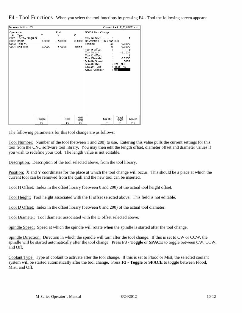
M-Series Operator’s Manual 8/24/2012 10-12
F4 - Tool Functions When you select the tool functions by pressing F4 - Tool the following screen appears:
The following parameters for this tool change are as follows: Tool Number: Number of the tool (between 1 and 200) to use. Entering this value pulls the current settings for this tool from the CNC software tool library. You may then edit the length offset, diameter offset and diameter values if you wish to redefine your tool. The length value is not editable. Description: Description of the tool selected above, from the tool library. Position: X and Y coordinates for the place at which the tool change will occur. This should be a place at which the current tool can be removed from the quill and the new tool can be inserted. Tool H Offset: Index in the offset library (between 0 and 200) of the actual tool height offset. Tool Height: Tool height associated with the H offset selected above. This field is not editable. Tool D Offset: Index in the offset library (between 0 and 200) of the actual tool diameter. Tool Diameter: Tool diameter associated with the D offset selected above. Spindle Speed: Speed at which the spindle will rotate when the spindle is started after the tool change. Spindle Direction: Direction in which the spindle will turn after the tool change. If this is set to CW or CCW, the spindle will be started automatically after the tool change. Press F3 - Toggle or SPACE to toggle between CW, CCW, and Off. Coolant Type: Type of coolant to activate after the tool change. If this is set to Flood or Mist, the selected coolant system will be started automatically after the tool change. Press F3 - Toggle or SPACE to toggle between Flood, Mist, and Off.
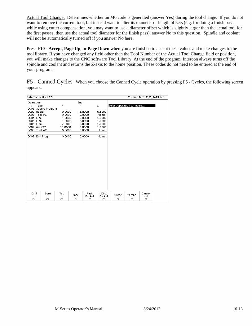
M-Series Operator’s Manual 8/24/2012 10-13
Actual Tool Change: Determines whether an M6 code is generated (answer Yes) during the tool change. If you do not want to remove the current tool, but instead want to alter its diameter or length offsets (e.g. for doing a finish pass while using cutter compensation, you may want to use a diameter offset which is slightly larger than the actual tool for the first passes, then use the actual tool diameter for the finish pass), answer No to this question. Spindle and coolant will not be automatically turned off if you answer No here. Press F10 - Accept, Page Up, or Page Down when you are finished to accept these values and make changes to the tool library. If you have changed any field other than the Tool Number of the Actual Tool Change field or position, you will make changes to the CNC software Tool Library. At the end of the program, Intercon always turns off the spindle and coolant and returns the Z-axis to the home position. These codes do not need to be entered at the end of your program. F5 - Canned Cycles When you choose the Canned Cycle operation by pressing F5 - Cycles, the following screen appears:
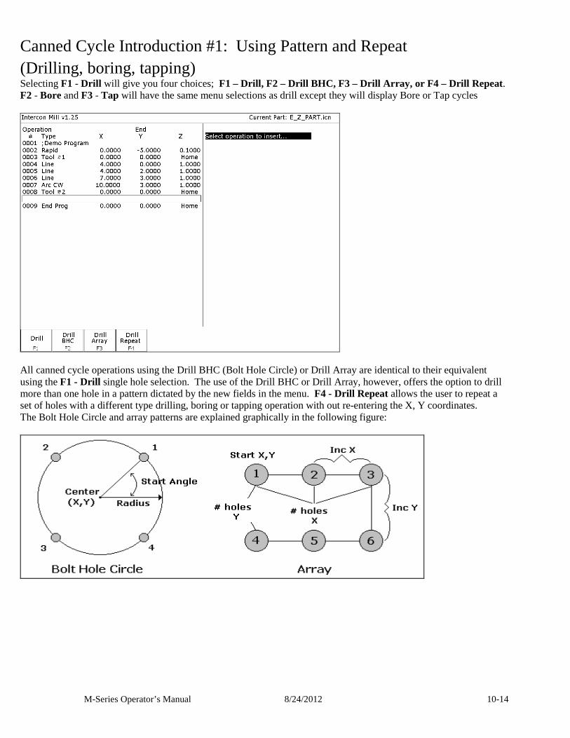
M-Series Operator’s Manual 8/24/2012 10-14
Canned Cycle Introduction #1: Using Pattern and Repeat (Drilling, boring, tapping) Selecting F1 - Drill will give you four choices; F1 – Drill, F2 – Drill BHC, F3 – Drill Array, or F4 – Drill Repeat. F2 - Bore and F3 - Tap will have the same menu selections as drill except they will display Bore or Tap cycles
All canned cycle operations using the Drill BHC (Bolt Hole Circle) or Drill Array are identical to their equivalent using the F1 - Drill single hole selection. The use of the Drill BHC or Drill Array, however, offers the option to drill more than one hole in a pattern dictated by the new fields in the menu. F4 - Drill Repeat allows the user to repeat a set of holes with a different type drilling, boring or tapping operation with out re-entering the X, Y coordinates. The Bolt Hole Circle and array patterns are explained graphically in the following figure:
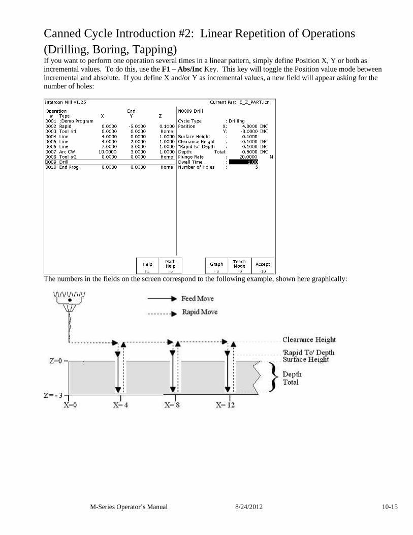
M-Series Operator’s Manual 8/24/2012 10-15
Canned Cycle Introduction #2: Linear Repetition of Operations (Drilling, Boring, Tapping) If you want to perform one operation several times in a linear pattern, simply define Position X, Y or both as incremental values. To do this, use the F1 – Abs/Inc Key. This key will toggle the Position value mode between incremental and absolute. If you define X and/or Y as incremental values, a new field will appear asking for the number of holes:
The numbers in the fields on the screen correspond to the following example, shown here graphically:
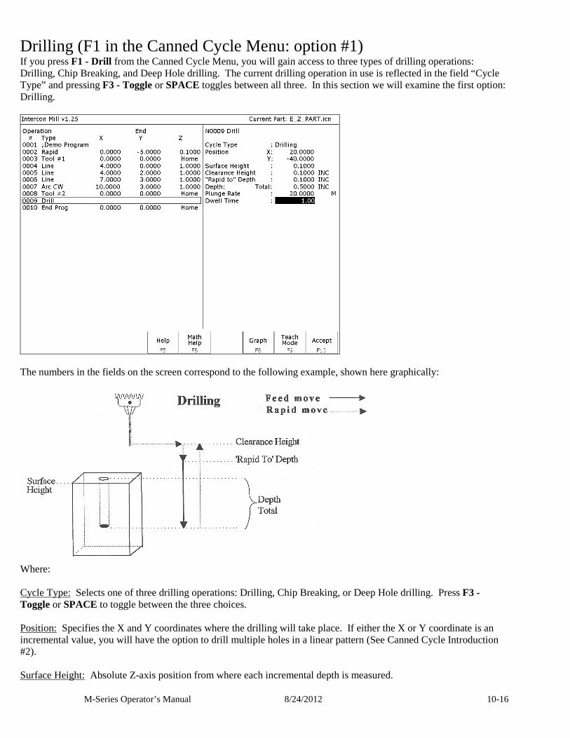
M-Series Operator’s Manual 8/24/2012 10-16
Drilling (F1 in the Canned Cycle Menu: option #1) If you press F1 - Drill from the Canned Cycle Menu, you will gain access to three types of drilling operations: Drilling, Chip Breaking, and Deep Hole drilling. The current drilling operation in use is reflected in the field “Cycle Type” and pressing F3 - Toggle or SPACE toggles between all three. In this section we will examine the first option: Drilling.
The numbers in the fields on the screen correspond to the following example, shown here graphically:
Where: Cycle Type: Selects one of three drilling operations: Drilling, Chip Breaking, or Deep Hole drilling. Press F3 - Toggle or SPACE to toggle between the three choices. Position: Specifies the X and Y coordinates where the drilling will take place. If either the X or Y coordinate is an incremental value, you will have the option to drill multiple holes in a linear pattern (See Canned Cycle Introduction #2). Surface Height: Absolute Z-axis position from where each incremental depth is measured.
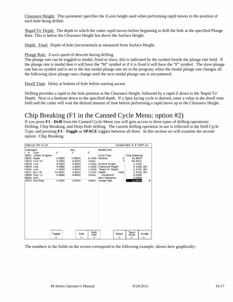
M-Series Operator’s Manual 8/24/2012 10-17
Clearance Height: This parameter specifies the Z-axis height used when performing rapid moves to the position of each hole being drilled. 'Rapid To' Depth: The depth to which the cutter rapid moves before beginning to drill the hole at the specified Plunge Rate. This is below the Clearance Height but above the Surface Height. Depth: Total: Depth of hole (incremental) as measured from Surface Height. Plunge Rate: Z-axis speed of descent during drilling. The plunge rate can be toggled to modal, fixed or slave, this is indicated by the symbol beside the plunge rate field. If the plunge rate is modal then it will have the “M” symbol or if it is fixed it will have the “F” symbol. The slave plunge rate has no symbol and is set to the last modal plunge rate set in the program, when the modal plunge rate changes all the following slave plunge rates change until the next modal plunge rate is encountered. Dwell Time: Delay at bottom of hole before starting ascent. Drilling provides a rapid to the hole position at the Clearance Height, followed by a rapid Z down to the 'Rapid To' Depth. Next is a feedrate down to the specified depth. If a Spot facing cycle is desired, enter a value in the dwell time field and the cutter will wait the desired amount of time before performing a rapid move up to the Clearance Height.
Chip Breaking (F1 in the Canned Cycle Menu: option #2) If you press F1 - Drill from the Canned Cycle Menu you will gain access to three types of drilling operations: Drilling, Chip Breaking, and Deep Hole drilling. The current drilling operation in use is reflected in the field Cycle Type, and pressing F3 - Toggle or SPACE toggles between all three. In this section we will examine the second option: Chip Breaking.
The numbers in the fields on the screen correspond to the following example, shown here graphically:
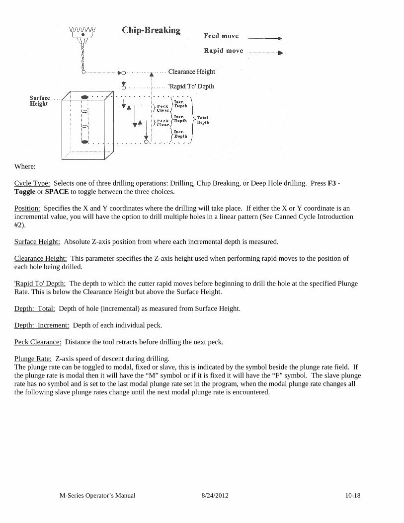
M-Series Operator’s Manual 8/24/2012 10-18
Where: Cycle Type: Selects one of three drilling operations: Drilling, Chip Breaking, or Deep Hole drilling. Press F3 - Toggle or SPACE to toggle between the three choices. Position: Specifies the X and Y coordinates where the drilling will take place. If either the X or Y coordinate is an incremental value, you will have the option to drill multiple holes in a linear pattern (See Canned Cycle Introduction #2). Surface Height: Absolute Z-axis position from where each incremental depth is measured. Clearance Height: This parameter specifies the Z-axis height used when performing rapid moves to the position of each hole being drilled. 'Rapid To' Depth: The depth to which the cutter rapid moves before beginning to drill the hole at the specified Plunge Rate. This is below the Clearance Height but above the Surface Height. Depth: Total: Depth of hole (incremental) as measured from Surface Height. Depth: Increment: Depth of each individual peck. Peck Clearance: Distance the tool retracts before drilling the next peck. Plunge Rate: Z-axis speed of descent during drilling. The plunge rate can be toggled to modal, fixed or slave, this is indicated by the symbol beside the plunge rate field. If the plunge rate is modal then it will have the “M” symbol or if it is fixed it will have the “F” symbol. The slave plunge rate has no symbol and is set to the last modal plunge rate set in the program, when the modal plunge rate changes all the following slave plunge rates change until the next modal plunge rate is encountered.
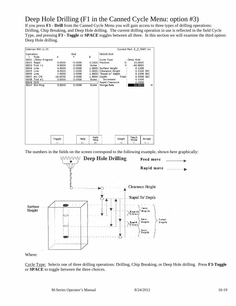
M-Series Operator’s Manual 8/24/2012 10-19
Deep Hole Drilling (F1 in the Canned Cycle Menu: option #3) If you press F1 - Drill from the Canned Cycle Menu you will gain access to three types of drilling operations: Drilling, Chip Breaking, and Deep Hole drilling. The current drilling operation in use is reflected in the field Cycle Type, and pressing F3 - Toggle or SPACE toggles between all three. In this section we will examine the third option: Deep Hole drilling.
The numbers in the fields on the screen correspond to the following example, shown here graphically:
Where: Cycle Type: Selects one of three drilling operations: Drilling, Chip Breaking, or Deep Hole drilling. Press F3-Toggle or SPACE to toggle between the three choices.
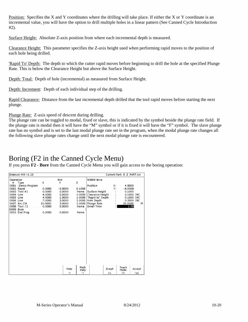
M-Series Operator’s Manual 8/24/2012 10-20
Position: Specifies the X and Y coordinates where the drilling will take place. If either the X or Y coordinate is an incremental value, you will have the option to drill multiple holes in a linear pattern (See Canned Cycle Introduction #2). Surface Height: Absolute Z-axis position from where each incremental depth is measured. Clearance Height: This parameter specifies the Z-axis height used when performing rapid moves to the position of each hole being drilled. 'Rapid To' Depth: The depth to which the cutter rapid moves before beginning to drill the hole at the specified Plunge Rate. This is below the Clearance Height but above the Surface Height. Depth: Total: Depth of hole (incremental) as measured from Surface Height. Depth: Increment: Depth of each individual step of the drilling. Rapid Clearance: Distance from the last incremental depth drilled that the tool rapid moves before starting the next plunge. Plunge Rate: Z-axis speed of descent during drilling. The plunge rate can be toggled to modal, fixed or slave, this is indicated by the symbol beside the plunge rate field. If the plunge rate is modal then it will have the “M” symbol or if it is fixed it will have the “F” symbol. The slave plunge rate has no symbol and is set to the last modal plunge rate set in the program, when the modal plunge rate changes all the following slave plunge rates change until the next modal plunge rate is encountered.
Boring (F2 in the Canned Cycle Menu) If you press F2 - Bore from the Canned Cycle Menu you will gain access to the boring operation:
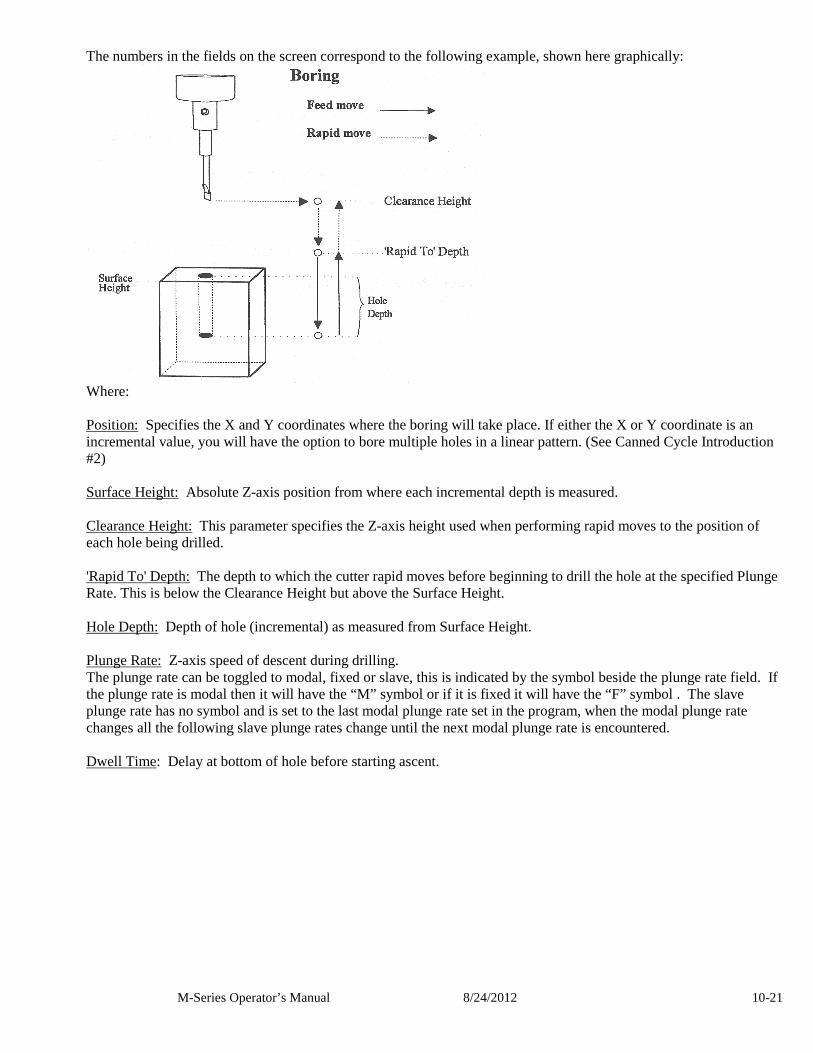
M-Series Operator’s Manual 8/24/2012 10-21
The numbers in the fields on the screen correspond to the following example, shown here graphically:
Where: Position: Specifies the X and Y coordinates where the boring will take place. If either the X or Y coordinate is an incremental value, you will have the option to bore multiple holes in a linear pattern. (See Canned Cycle Introduction #2) Surface Height: Absolute Z-axis position from where each incremental depth is measured. Clearance Height: This parameter specifies the Z-axis height used when performing rapid moves to the position of each hole being drilled. 'Rapid To' Depth: The depth to which the cutter rapid moves before beginning to drill the hole at the specified Plunge Rate. This is below the Clearance Height but above the Surface Height. Hole Depth: Depth of hole (incremental) as measured from Surface Height. Plunge Rate: Z-axis speed of descent during drilling. The plunge rate can be toggled to modal, fixed or slave, this is indicated by the symbol beside the plunge rate field. If the plunge rate is modal then it will have the “M” symbol or if it is fixed it will have the “F” symbol . The slave plunge rate has no symbol and is set to the last modal plunge rate set in the program, when the modal plunge rate changes all the following slave plunge rates change until the next modal plunge rate is encountered. Dwell Time: Delay at bottom of hole before starting ascent.
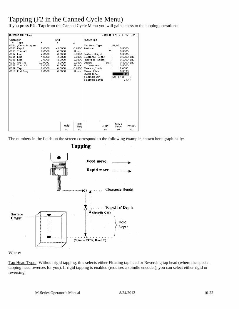
M-Series Operator’s Manual 8/24/2012 10-22
Tapping (F2 in the Canned Cycle Menu) If you press F2 - Tap from the Canned Cycle Menu you will gain access to the tapping operations:
The numbers in the fields on the screen correspond to the following example, shown here graphically:
Where: Tap Head Type: Without rigid tapping, this selects either Floating tap head or Reversing tap head (where the special tapping head reverses for you). If rigid tapping is enabled (requires a spindle encoder), you can select either rigid or reversing.
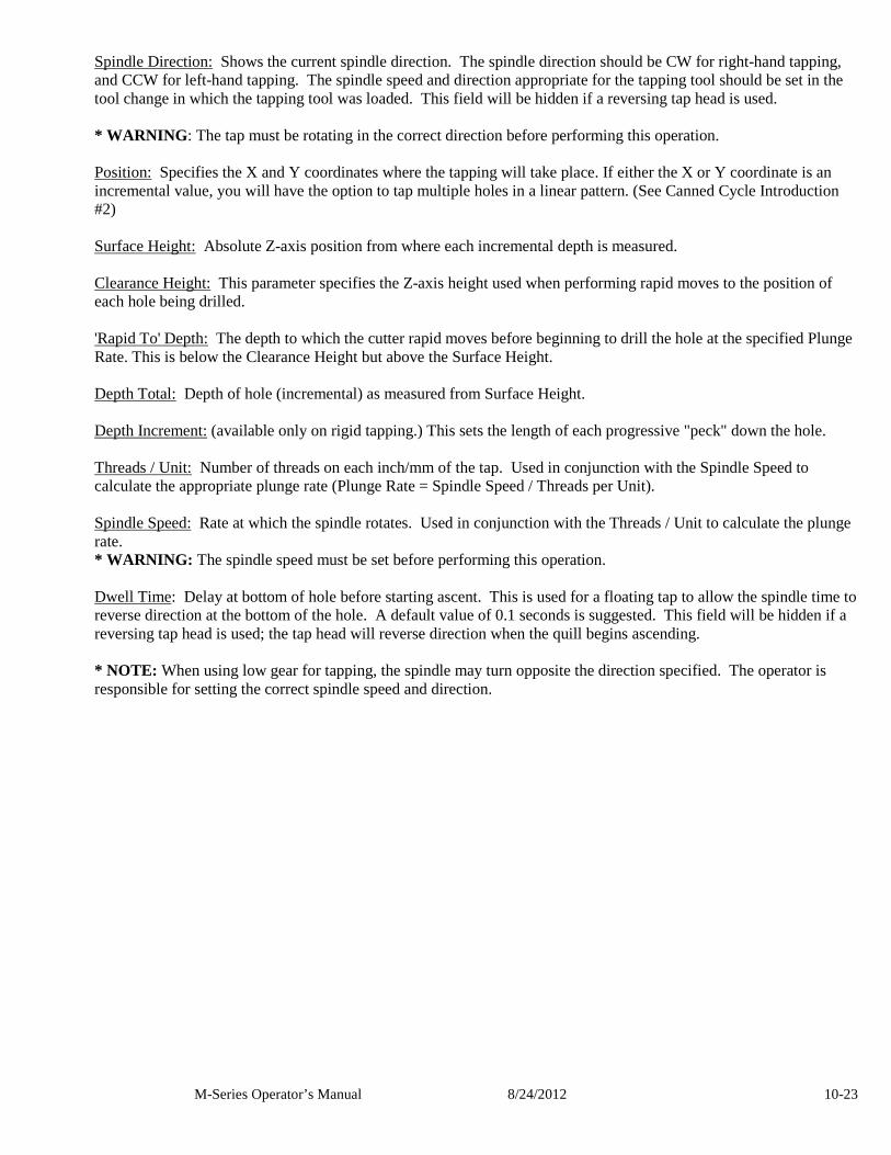
M-Series Operator’s Manual 8/24/2012 10-23
Spindle Direction: Shows the current spindle direction. The spindle direction should be CW for right-hand tapping, and CCW for left-hand tapping. The spindle speed and direction appropriate for the tapping tool should be set in the tool change in which the tapping tool was loaded. This field will be hidden if a reversing tap head is used. * WARNING : The tap must be rotating in the correct direction before performing this operation. Position: Specifies the X and Y coordinates where the tapping will take place. If either the X or Y coordinate is an incremental value, you will have the option to tap multiple holes in a linear pattern. (See Canned Cycle Introduction #2) Surface Height: Absolute Z-axis position from where each incremental depth is measured. Clearance Height: This parameter specifies the Z-axis height used when performing rapid moves to the position of each hole being drilled. 'Rapid To' Depth: The depth to which the cutter rapid moves before beginning to drill the hole at the specified Plunge Rate. This is below the Clearance Height but above the Surface Height. Depth Total: Depth of hole (incremental) as measured from Surface Height. Depth Increment: (available only on rigid tapping.) This sets the length of each progressive "peck" down the hole. Threads / Unit: Number of threads on each inch/mm of the tap. Used in conjunction with the Spindle Speed to calculate the appropriate plunge rate (Plunge Rate = Spindle Speed / Threads per Unit). Spindle Speed: Rate at which the spindle rotates. Used in conjunction with the Threads / Unit to calculate the plunge rate. * WARNING: The spindle speed must be set before performing this operation. Dwell Time: Delay at bottom of hole before starting ascent. This is used for a floating tap to allow the spindle time to reverse direction at the bottom of the hole. A default value of 0.1 seconds is suggested. This field will be hidden if a reversing tap head is used; the tap head will reverse direction when the quill begins ascending. * NOTE: When using low gear for tapping, the spindle may turn opposite the direction specified. The operator is responsible for setting the correct spindle speed and direction.
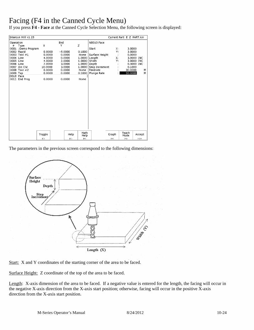
M-Series Operator’s Manual 8/24/2012 10-24
Facing (F4 in the Canned Cycle Menu) If you press F4 - Face at the Canned Cycle Selection Menu, the following screen is displayed:
The parameters in the previous screen correspond to the following dimensions:
Start: X and Y coordinates of the starting corner of the area to be faced. Surface Height: Z coordinate of the top of the area to be faced. Length: X-axis dimension of the area to be faced. If a negative value is entered for the length, the facing will occur in the negative X-axis direction from the X-axis start position; otherwise, facing will occur in the positive X-axis direction from the X-axis start position.
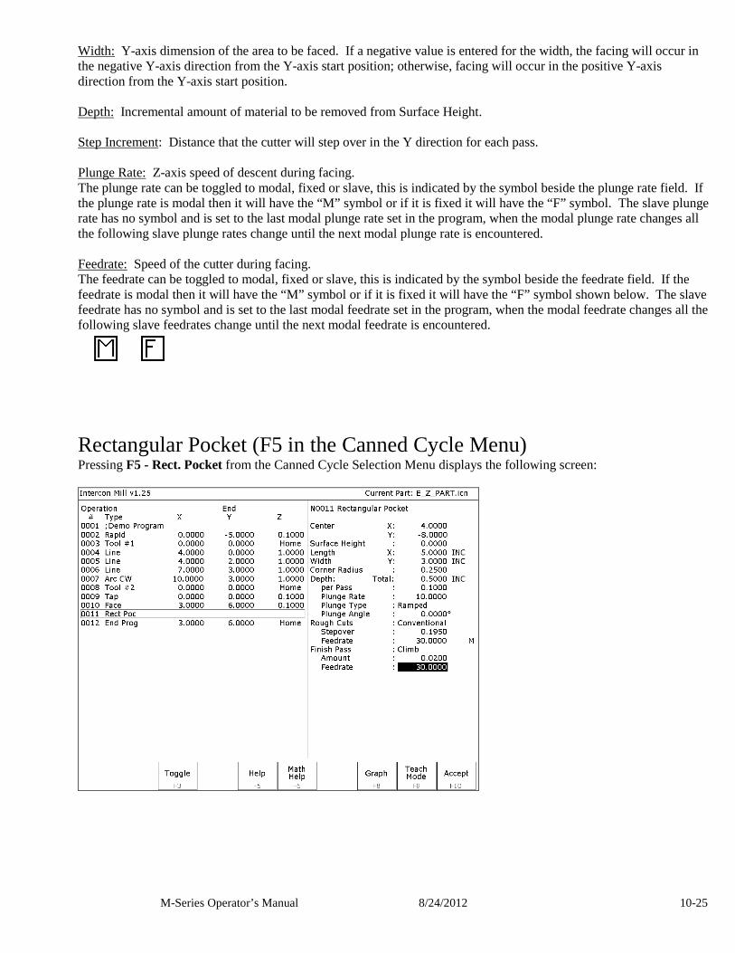
M-Series Operator’s Manual 8/24/2012 10-25
Width: Y-axis dimension of the area to be faced. If a negative value is entered for the width, the facing will occur in the negative Y-axis direction from the Y-axis start position; otherwise, facing will occur in the positive Y-axis direction from the Y-axis start position. Depth: Incremental amount of material to be removed from Surface Height. Step Increment: Distance that the cutter will step over in the Y direction for each pass. Plunge Rate: Z-axis speed of descent during facing. The plunge rate can be toggled to modal, fixed or slave, this is indicated by the symbol beside the plunge rate field. If the plunge rate is modal then it will have the “M” symbol or if it is fixed it will have the “F” symbol. The slave plunge rate has no symbol and is set to the last modal plunge rate set in the program, when the modal plunge rate changes all the following slave plunge rates change until the next modal plunge rate is encountered. Feedrate: Speed of the cutter during facing. The feedrate can be toggled to modal, fixed or slave, this is indicated by the symbol beside the feedrate field. If the feedrate is modal then it will have the “M” symbol or if it is fixed it will have the “F” symbol shown below. The slave feedrate has no symbol and is set to the last modal feedrate set in the program, when the modal feedrate changes all the following slave feedrates change until the next modal feedrate is encountered.
Rectangular Pocket (F5 in the Canned Cycle Menu) Pressing F5 - Rect. Pocket from the Canned Cycle Selection Menu displays the following screen:
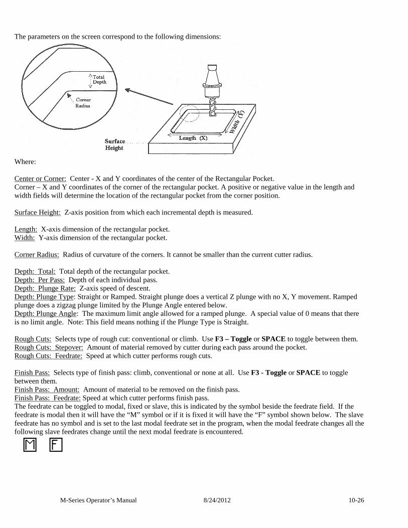
M-Series Operator’s Manual 8/24/2012 10-26
The parameters on the screen correspond to the following dimensions:
Where: Center or Corner: Center - X and Y coordinates of the center of the Rectangular Pocket. Corner – X and Y coordinates of the corner of the rectangular pocket. A positive or negative value in the length and width fields will determine the location of the rectangular pocket from the corner position. Surface Height: Z-axis position from which each incremental depth is measured. Length: X-axis dimension of the rectangular pocket. Width: Y-axis dimension of the rectangular pocket. Corner Radius: Radius of curvature of the corners. It cannot be smaller than the current cutter radius. Depth: Total: Total depth of the rectangular pocket. Depth: Per Pass: Depth of each individual pass. Depth: Plunge Rate: Z-axis speed of descent. Depth: Plunge Type: Straight or Ramped. Straight plunge does a vertical Z plunge with no X, Y movement. Ramped plunge does a zigzag plunge limited by the Plunge Angle entered below. Depth: Plunge Angle: The maximum limit angle allowed for a ramped plunge. A special value of 0 means that there is no limit angle. Note: This field means nothing if the Plunge Type is Straight. Rough Cuts: Selects type of rough cut: conventional or climb. Use F3 – Toggle or SPACE to toggle between them. Rough Cuts: Stepover: Amount of material removed by cutter during each pass around the pocket. Rough Cuts: Feedrate: Speed at which cutter performs rough cuts. Finish Pass: Selects type of finish pass: climb, conventional or none at all. Use F3 - Toggle or SPACE to toggle between them. Finish Pass: Amount: Amount of material to be removed on the finish pass. Finish Pass: Feedrate: Speed at which cutter performs finish pass. The feedrate can be toggled to modal, fixed or slave, this is indicated by the symbol beside the feedrate field. If the feedrate is modal then it will have the “M” symbol or if it is fixed it will have the “F” symbol shown below. The slave feedrate has no symbol and is set to the last modal feedrate set in the program, when the modal feedrate changes all the following slave feedrates change until the next modal feedrate is encountered.
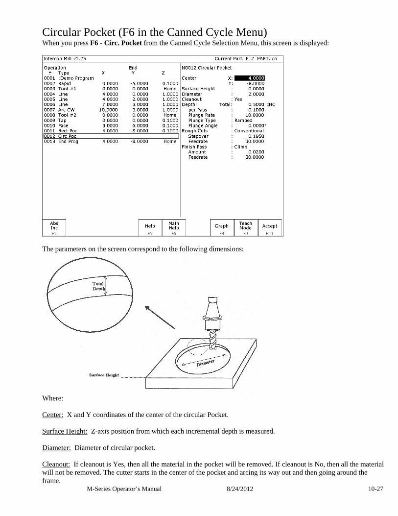
M-Series Operator’s Manual 8/24/2012 10-27
Circular Pocket (F6 in the Canned Cycle Menu) When you press F6 - Circ. Pocket from the Canned Cycle Selection Menu, this screen is displayed:
The parameters on the screen correspond to the following dimensions:
Where: Center: X and Y coordinates of the center of the circular Pocket. Surface Height: Z-axis position from which each incremental depth is measured. Diameter: Diameter of circular pocket. Cleanout: If cleanout is Yes, then all the material in the pocket will be removed. If cleanout is No, then all the material will not be removed. The cutter starts in the center of the pocket and arcing its way out and then going around the frame.
M-Series Operator’s Manual 8/24/2012 10-28
Depth: Total: Total depth of the circular pocket. Depth: Per Pass: Depth of each individual pass. Depth: Plunge Rate: Z-axis speed of descent. Depth: Plunge Type: Straight or Ramped. Straight plunge does a vertical Z plunge with no X, Y movement. Ramped plunge does a zigzag plunge limited by the Plunge Angle entered below. Depth: Plunge Angle: The maximum limit angle allowed for a ramped plunge. A special value of 0 means that there is no limit angle. Note: This field means nothing if the Plunge Type is Straight. Rough Cuts: Selects type of rough cut: conventional or climb. Use F3 - Toggle or SPACE to toggle between them. Rough Cuts: Stepover: Amount of material removed by cutter during each pass around the pocket. Rough Cuts: Feedrate: Speed at which cutter performs rough cuts. Finish Pass: Selects type of finish pass: climb, conventional or none at all. Use F3 - Toggle or SPACE to toggle. Finish Pass: Amount: Amount of material to be removed on the finish pass. Finish Pass: Feedrate: Speed at which cutter performs finish pass.
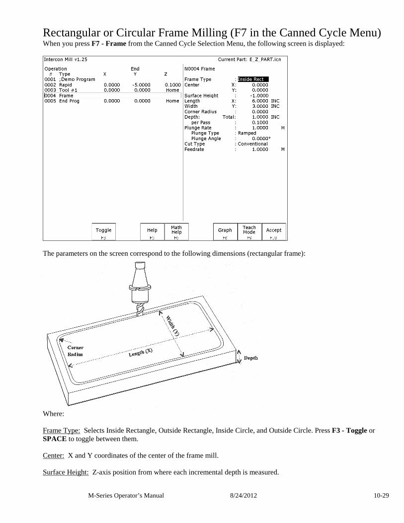
M-Series Operator’s Manual 8/24/2012 10-29
Rectangular or Circular Frame Milling (F7 in the Canned Cycle Menu) When you press F7 - Frame from the Canned Cycle Selection Menu, the following screen is displayed:
The parameters on the screen correspond to the following dimensions (rectangular frame):
Where: Frame Type: Selects Inside Rectangle, Outside Rectangle, Inside Circle, and Outside Circle. Press F3 - Toggle or SPACE to toggle between them. Center: X and Y coordinates of the center of the frame mill. Surface Height: Z-axis position from where each incremental depth is measured.
M-Series Operator’s Manual 8/24/2012 10-30
Length: X-axis dimension of the frame mill. (Rectangular frame only.) Width: Y-axis dimension of the frame mill. (Rectangular frame only.) Corner Radius: Radius of curvature of the corners. On an Inside frame, corner radius must be greater than the current cutter radius. (Rectangular frame only.) Diameter: Diameter of the frame mill. (Circular frame only) Depth: Total: Total depth of the frame mill. Depth: Per Pass: Depth of each individual pass. Plunge Rate: Z-axis speed of descent. Plunge Type: Straight or Ramped. Straight plunge does a vertical Z plunge with no X, Y movement. Ramped plunge does a zigzag plunge limited by the Plunge Angle entered below. Plunge Angle: The maximum limit angle allowed for a ramped plunge. A special value of 0 means that there is no limit angle. Note: This field means nothing if the Plunge Type is Straight. Entrance Type: Selects type of entrance: Arc On or Arc Off, use F3 - Toggle or SPACE to toggle between them. (Circular frame only) Cut type: Selects type of cut: conventional or climb, use F3 - Toggle or SPACE to toggle between them. Feedrate: Speed at which the cutter performs frame mill. NOTE: To make a circular frame mill of radius R, specify R as the Corner Radius and set the Length and Width parameters equal to 2 x R.
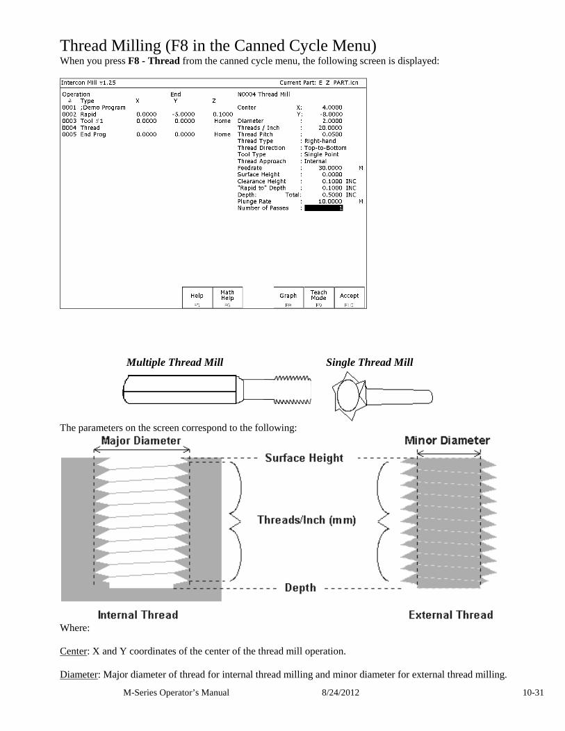
M-Series Operator’s Manual 8/24/2012 10-31
Thread Milling (F8 in the Canned Cycle Menu) When you press F8 - Thread from the canned cycle menu, the following screen is displayed:
Multiple Thread Mill Single Thread Mill
The parameters on the screen correspond to the following:
Where: Center: X and Y coordinates of the center of the thread mill operation. Diameter: Major diameter of thread for internal thread milling and minor diameter for external thread milling.
M-Series Operator’s Manual 8/24/2012 10-32
Thread / Unit: Number of threads per inch or mm. Used to calculate thread pitch. Thread Pitch: Thread pitch calculated from threads/unit field. This field cannot be modified. Thread Type: Specifies right or left hand threads. Thread Direction: Specifies whether to start at the bottom of the hole and work up or start at the top of the hole and work down. Tool Type: Single point or full form threading tool. Thread Approach: Internal or external thread. Clearance Amount: Used for external thread milling only. Specifies the diameter of the lead-in arc. Minimum clearance is 0.050 inches. Clearance Angle: Used for external thread milling only. Specifies the angle from which the lead in arc will start. Feedrate: Cutting feed rate. Surface Height: Absolute Z-axis position from position from where the incremental depth is measured. Clearance Height: This parameter specifies the Z axis height used when performing rapid moves to the position of each hole being thread. 'Rapid to' Depth: The depth to which the cutter rapid moves before beginning to thread mill at the specified Plunge Rate. This is below the Clearance Height but above the Surface Height. Depth: The total depth of the thread. Number of Passes: Number of times the thread mill is to be done on the same hole.
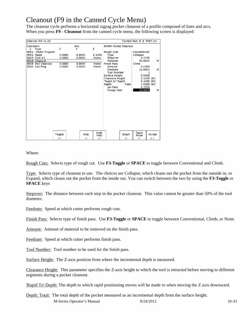
M-Series Operator’s Manual 8/24/2012 10-33
Cleanout (F9 in the Canned Cycle Menu) The cleanout cycle performs a horizontal zigzag pocket cleanout of a profile composed of lines and arcs. When you press F9 - Cleanout from the canned cycle menu, the following screen is displayed:
Where: Rough Cuts: Selects type of rough cut. Use F3-Toggle or SPACE to toggle between Conventional and Climb. Type: Selects type of cleanout to use. The choices are Collapse, which cleans out the pocket from the outside in, or Expand, which cleans out the pocket from the inside out. You can switch between the two by using the F3-Toggle or SPACE keys Stepover: The distance between each step in the pocket cleanout. This value cannot be greater than 50% of the tool diameter. Feedrate: Speed at which cutter performs rough cuts. Finish Pass: Selects type of finish pass. Use F3-Toggle or SPACE to toggle between Conventional, Climb, or None. Amount: Amount of material to be removed on the finish pass. Feedrate: Speed at which cutter performs finish pass. Tool Number: Tool number to be used for the finish pass. Surface Height: The Z-axis position from where the incremental depth is measured. Clearance Height: This parameter specifies the Z-axis height to which the tool is retracted before moving to different segments during a pocket cleanout. 'Rapid To' Depth: The depth to which rapid positioning moves will be made to when moving the Z axis downward. Depth: Total: The total depth of the pocket measured as an incremental depth from the surface height.
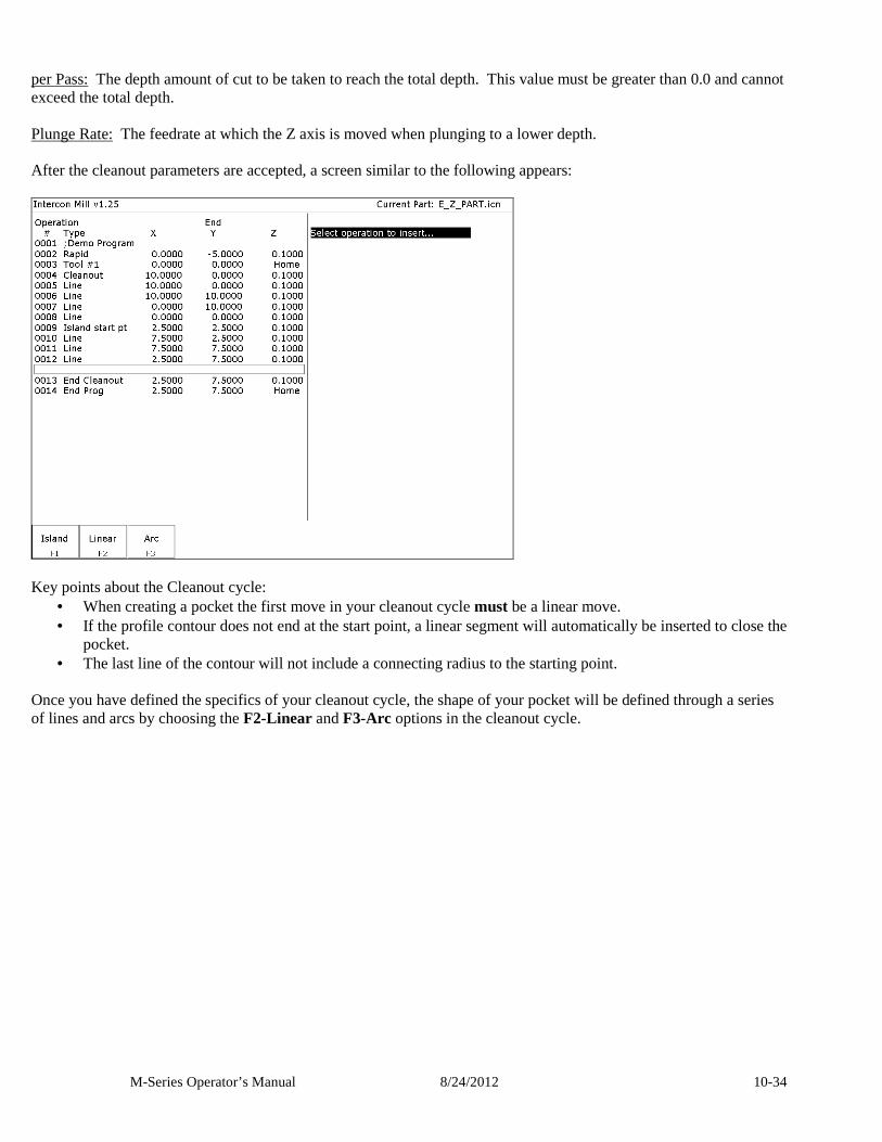
M-Series Operator’s Manual 8/24/2012 10-34
per Pass: The depth amount of cut to be taken to reach the total depth. This value must be greater than 0.0 and cannot exceed the total depth. Plunge Rate: The feedrate at which the Z axis is moved when plunging to a lower depth. After the cleanout parameters are accepted, a screen similar to the following appears:
Key points about the Cleanout cycle:
• When creating a pocket the first move in your cleanout cycle must be a linear move. • If the profile contour does not end at the start point, a linear segment will automatically be inserted to close the
pocket. • The last line of the contour will not include a connecting radius to the starting point.
Once you have defined the specifics of your cleanout cycle, the shape of your pocket will be defined through a series of lines and arcs by choosing the F2-Linear and F3-Arc options in the cleanout cycle.
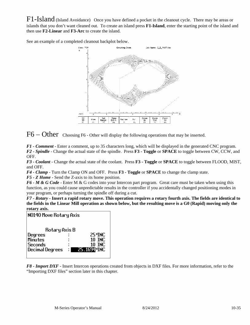
M-Series Operator’s Manual 8/24/2012 10-35
F1-Island (Island Avoidance) Once you have defined a pocket in the cleanout cycle. There may be areas or islands that you don’t want cleaned out. To create an island press F1-Island, enter the starting point of the island and then use F2-Linear and F3-Arc to create the island. See an example of a completed cleanout backplot below.
F6 – Other Choosing F6 - Other will display the following operations that may be inserted. F1 - Comment - Enter a comment, up to 35 characters long, which will be displayed in the generated CNC program. F2 - Spindle - Change the actual state of the spindle. Press F3 - Toggle or SPACE to toggle between CW, CCW, and OFF. F3 - Coolant - Change the actual state of the coolant. Press F3 - Toggle or SPACE to toggle between FLOOD, MIST, and OFF. F4 - Clamp - Turn the Clamp ON and OFF. Press F3 - Toggle or SPACE to change the clamp state. F5 - Z Home - Send the Z-axis to its home position. F6 - M & G Code - Enter M & G codes into your Intercon part program. Great care must be taken when using this function, as you could cause unpredictable results in the controller if you accidentally changed positioning modes in your program, or perhaps turning the spindle off during a cut. F7 - Rotary - Insert a rapid rotary move. This operation requires a rotary fourth axis. The fields are identical to the fields in the Linear Mill operation as shown below, but the resulting move is a G0 (Rapid) moving only the rotary axis.
F8 - Import DXF - Insert Intercon operations created from objects in DXF files. For more information, refer to the “Importing DXF files” section later in this chapter.
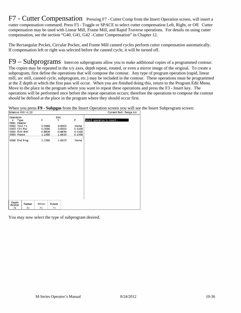
M-Series Operator’s Manual 8/24/2012 10-36
F7 - Cutter Compensation Pressing F7 - Cutter Comp from the Insert Operation screen, will insert a cutter compensation command. Press F3 - Toggle or SPACE to select cutter compensation Left, Right, or Off. Cutter compensation may be used with Linear Mill, Frame Mill, and Rapid Traverse operations. For details on using cutter compensation, see the section “G40, G41, G42 –Cutter Compensation” in Chapter 12. The Rectangular Pocket, Circular Pocket, and Frame Mill canned cycles perform cutter compensation automatically. If compensation left or right was selected before the canned cycle, it will be turned off.
F9 – Subprograms Intercon subprograms allow you to make additional copies of a programmed contour. The copies may be repeated in the x/y axes, depth repeat, rotated, or even a mirror image of the original. To create a subprogram, first define the operations that will compose the contour. Any type of program operation (rapid, linear mill, arc mill, canned cycle, subprogram, etc.) may be included in the contour. These operations must be programmed at the Z depth at which the first pass will occur. When you are finished doing this, return to the Program Edit Menu. Move to the place in the program where you want to repeat these operations and press the F3 - Insert key. The operations will be performed once before the repeat operation occurs; therefore the operations to compose the contour should be defined at the place in the program where they should occur first. When you press F9 - Subpgm from the Insert Operation screen you will see the Insert Subprogram screen:
You may now select the type of subprogram desired.
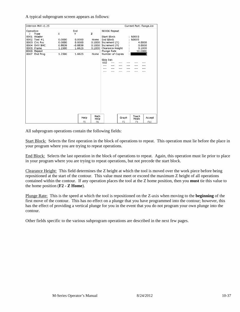
M-Series Operator’s Manual 8/24/2012 10-37
A typical subprogram screen appears as follows:
All subprogram operations contain the following fields: Start Block: Selects the first operation in the block of operations to repeat. This operation must lie before the place in your program where you are trying to repeat operations. End Block: Selects the last operation in the block of operations to repeat. Again, this operation must lie prior to place in your program where you are trying to repeat operations, but not precede the start block. Clearance Height: This field determines the Z height at which the tool is moved over the work piece before being repositioned at the start of the contour. This value must meet or exceed the maximum Z height of all operations contained within the contour. If any operation places the tool at the Z home position, then you must tie this value to the home position (F2 - Z Home). Plunge Rate: This is the speed at which the tool is repositioned on the Z-axis when moving to the beginning of the first move of the contour. This has no effect on a plunge that you have programmed into the contour; however, this has the effect of providing a vertical plunge for you in the event that you do not program your own plunge into the contour. Other fields specific to the various subprogram operations are described in the next few pages.
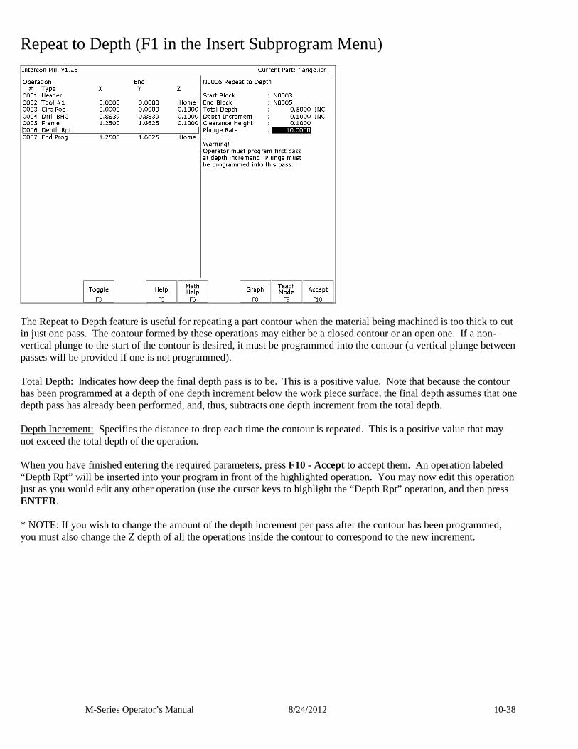
M-Series Operator’s Manual 8/24/2012 10-38
Repeat to Depth (F1 in the Insert Subprogram Menu)
The Repeat to Depth feature is useful for repeating a part contour when the material being machined is too thick to cut in just one pass. The contour formed by these operations may either be a closed contour or an open one. If a non-vertical plunge to the start of the contour is desired, it must be programmed into the contour (a vertical plunge between passes will be provided if one is not programmed). Total Depth: Indicates how deep the final depth pass is to be. This is a positive value. Note that because the contour has been programmed at a depth of one depth increment below the work piece surface, the final depth assumes that one depth pass has already been performed, and, thus, subtracts one depth increment from the total depth. Depth Increment: Specifies the distance to drop each time the contour is repeated. This is a positive value that may not exceed the total depth of the operation. When you have finished entering the required parameters, press F10 - Accept to accept them. An operation labeled “Depth Rpt” will be inserted into your program in front of the highlighted operation. You may now edit this operation just as you would edit any other operation (use the cursor keys to highlight the “Depth Rpt” operation, and then press ENTER. * NOTE: If you wish to change the amount of the depth increment per pass after the contour has been programmed, you must also change the Z depth of all the operations inside the contour to correspond to the new increment.
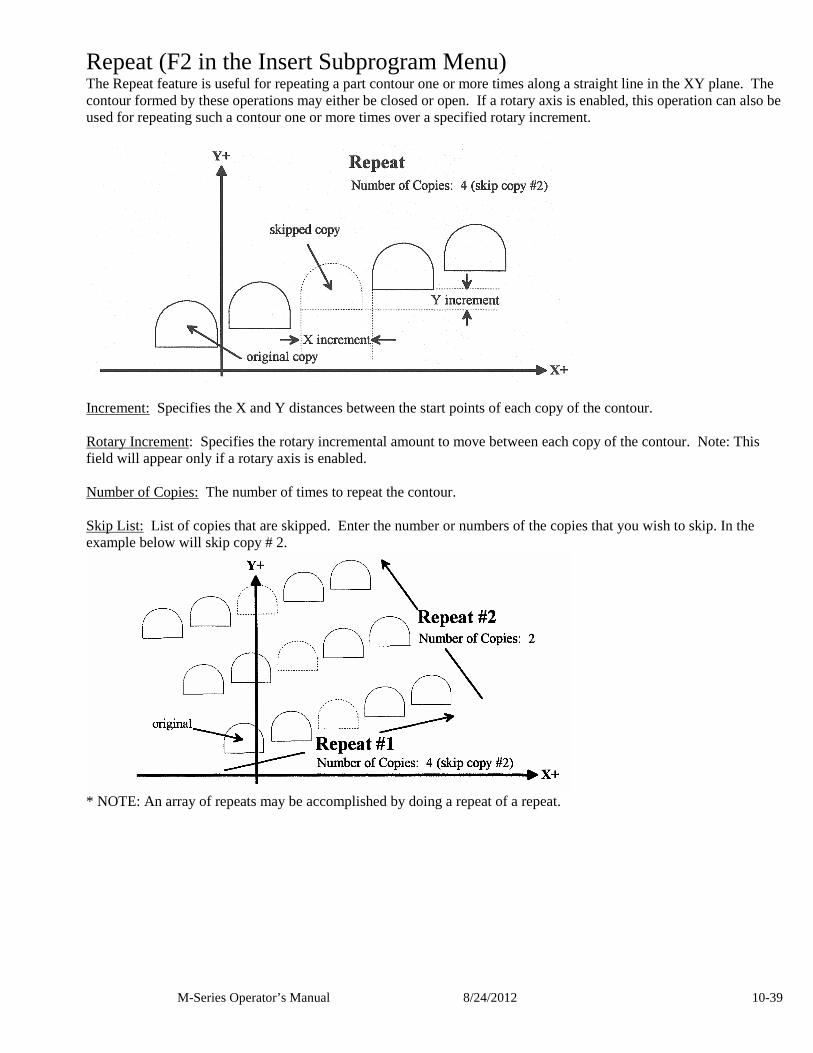
M-Series Operator’s Manual 8/24/2012 10-39
Repeat (F2 in the Insert Subprogram Menu) The Repeat feature is useful for repeating a part contour one or more times along a straight line in the XY plane. The contour formed by these operations may either be closed or open. If a rotary axis is enabled, this operation can also be used for repeating such a contour one or more times over a specified rotary increment.
Increment: Specifies the X and Y distances between the start points of each copy of the contour. Rotary Increment: Specifies the rotary incremental amount to move between each copy of the contour. Note: This field will appear only if a rotary axis is enabled. Number of Copies: The number of times to repeat the contour. Skip List: List of copies that are skipped. Enter the number or numbers of the copies that you wish to skip. In the example below will skip copy # 2.
* NOTE: An array of repeats may be accomplished by doing a repeat of a repeat.
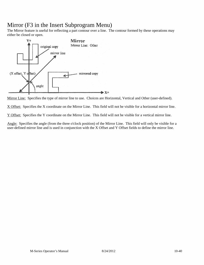
M-Series Operator’s Manual 8/24/2012 10-40
Mirror (F3 in the Insert Subprogram Menu) The Mirror feature is useful for reflecting a part contour over a line. The contour formed by these operations may either be closed or open.
Mirror Line: Specifies the type of mirror line to use. Choices are Horizontal, Vertical and Other (user-defined). X Offset: Specifies the X coordinate on the Mirror Line. This field will not be visible for a horizontal mirror line. Y Offset: Specifies the Y coordinate on the Mirror Line. This field will not be visible for a vertical mirror line. Angle: Specifies the angle (from the three o'clock position) of the Mirror Line. This field will only be visible for a user-defined mirror line and is used in conjunction with the X Offset and Y Offset fields to define the mirror line.
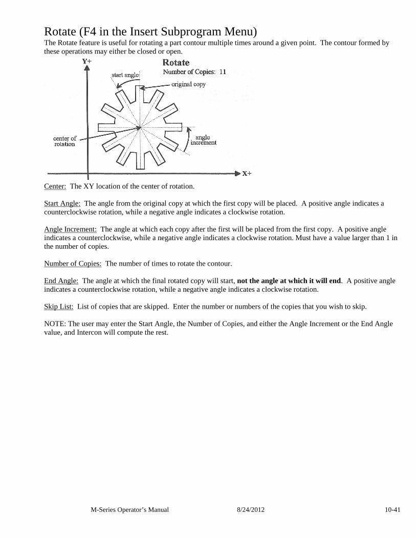
M-Series Operator’s Manual 8/24/2012 10-41
Rotate (F4 in the Insert Subprogram Menu) The Rotate feature is useful for rotating a part contour multiple times around a given point. The contour formed by these operations may either be closed or open.
Center: The XY location of the center of rotation. Start Angle: The angle from the original copy at which the first copy will be placed. A positive angle indicates a counterclockwise rotation, while a negative angle indicates a clockwise rotation. Angle Increment: The angle at which each copy after the first will be placed from the first copy. A positive angle indicates a counterclockwise, while a negative angle indicates a clockwise rotation. Must have a value larger than 1 in the number of copies. Number of Copies: The number of times to rotate the contour. End Angle: The angle at which the final rotated copy will start, not the angle at which it will end. A positive angle indicates a counterclockwise rotation, while a negative angle indicates a clockwise rotation. Skip List: List of copies that are skipped. Enter the number or numbers of the copies that you wish to skip. NOTE: The user may enter the Start Angle, the Number of Copies, and either the Angle Increment or the End Angle value, and Intercon will compute the rest.
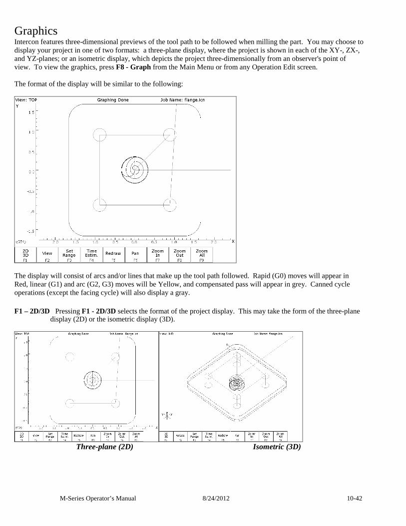
M-Series Operator’s Manual 8/24/2012 10-42
Graphics Intercon features three-dimensional previews of the tool path to be followed when milling the part. You may choose to display your project in one of two formats: a three-plane display, where the project is shown in each of the XY-, ZX-, and YZ-planes; or an isometric display, which depicts the project three-dimensionally from an observer's point of view. To view the graphics, press F8 - Graph from the Main Menu or from any Operation Edit screen. The format of the display will be similar to the following:
The display will consist of arcs and/or lines that make up the tool path followed. Rapid (G0) moves will appear in Red, linear (G1) and arc (G2, G3) moves will be Yellow, and compensated pass will appear in grey. Canned cycle operations (except the facing cycle) will also display a gray. F1 – 2D/3D Pressing F1 - 2D/3D selects the format of the project display. This may take the form of the three-plane
display (2D) or the isometric display (3D).
Three-plane (2D) Isometric (3D)
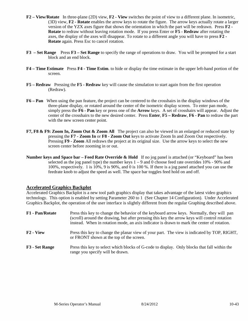
M-Series Operator’s Manual 8/24/2012 10-43
F2 – View/Rotate In three-plane (2D) view, F2 - View switches the point of view to a different plane. In isometric, (3D) view, F2 - Rotate enables the arrow keys to rotate the figure. The arrow keys actually rotate a larger version of the YZX axes figure that shows the orientation in which the part will be redrawn. Press F2 - Rotate to redraw without leaving rotation mode. If you press Enter or F5 - Redraw after rotating the axes, the display of the axes will disappear. To rotate to a different angle you will have to press F2 - Rotate again. Press Esc to cancel rotation.
F3 – Set Range Press F3 – Set Range to specify the range of operations to draw. You will be prompted for a start
block and an end block. F4 – Time Estimate Press F4 - Time Estim. to hide or display the time estimate in the upper left-hand portion of the
screen. F5 – Redraw Pressing the F5 - Redraw key will cause the simulation to start again from the first operation
(Redraw). F6 – Pan When using the pan feature, the project can be centered to the crosshairs in the display windows of the
three-plane display, or rotated around the center of the isometric display screen. To enter pan mode, simply press the F6 - Pan key or press one of the Arrow keys. A set of crosshairs will appear. Adjust the center of the crosshairs to the new desired center. Press Enter, F5 – Redraw, F6 - Pan to redraw the part with the new screen center point.
F7, F8 & F9: Zoom In, Zoom Out & Zoom All The project can also be viewed in an enlarged or reduced state by
pressing the F7 - Zoom In or F8 - Zoom Out keys to activate Zoom In and Zoom Out respectively. Pressing F9 - Zoom All redraws the project at its original size. Use the arrow keys to select the new screen center before zooming in or out.
Number keys and Space bar – Feed Rate Override & Hold If no jog panel is attached (or “Keyboard” has been
selected as the jog panel type) the number keys 1 – 9 and 0 choose feed rate overrides 10% - 90% and 100%, respectively. 1 is 10%, 9 is 90%, and 0 is 100 %. If there is a jog panel attached you can use the feedrate knob to adjust the speed as well. The space bar toggles feed hold on and off.
Accelerated Graphics Backplot Accelerated Graphics Backplot is a new tool path graphics display that takes advantage of the latest video graphics technology. This option is enabled by setting Parameter 260 to 1 (See Chapter 14 Configuration). Under Accelerated Graphics Backplot, the operation of the user interface is slightly different from the regular Graphing described above. F1 - Pan/Rotate Press this key to change the behavior of the keyboard arrow keys. Normally, they will pan
(scroll) around the drawing, but after pressing this key the arrow keys will control rotation instead. When in rotation mode, an axis indicator is drawn to mark the center of rotation.
F2 - View Press this key to change the planar view of your part. The view is indicated by TOP, RIGHT,
or FRONT shown at the top of the screen. F3 - Set Range Press this key to select which blocks of G-code to display. Only blocks that fall within the
range you specify will be drawn.
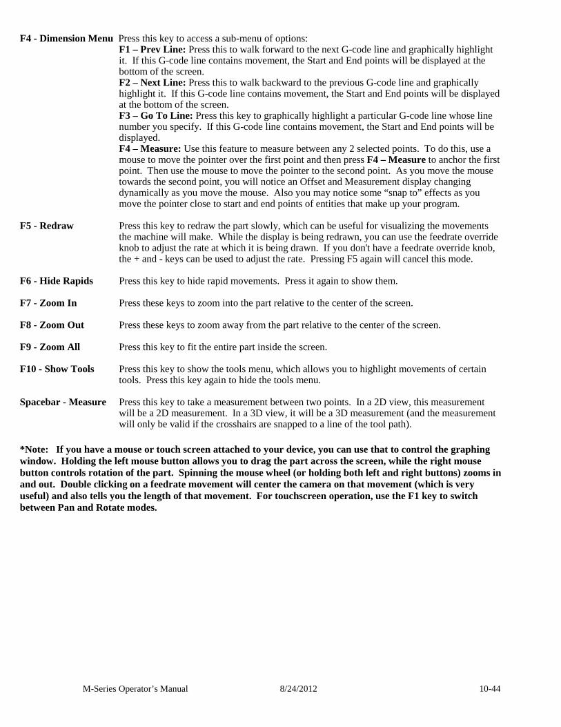
M-Series Operator’s Manual 8/24/2012 10-44
F4 - Dimension Menu Press this key to access a sub-menu of options: F1 – Prev Line: Press this to walk forward to the next G-code line and graphically highlight it. If this G-code line contains movement, the Start and End points will be displayed at the bottom of the screen. F2 – Next Line: Press this to walk backward to the previous G-code line and graphically highlight it. If this G-code line contains movement, the Start and End points will be displayed at the bottom of the screen. F3 – Go To Line: Press this key to graphically highlight a particular G-code line whose line number you specify. If this G-code line contains movement, the Start and End points will be displayed. F4 – Measure: Use this feature to measure between any 2 selected points. To do this, use a mouse to move the pointer over the first point and then press F4 – Measure to anchor the first point. Then use the mouse to move the pointer to the second point. As you move the mouse towards the second point, you will notice an Offset and Measurement display changing dynamically as you move the mouse. Also you may notice some “snap to” effects as you move the pointer close to start and end points of entities that make up your program.
F5 - Redraw Press this key to redraw the part slowly, which can be useful for visualizing the movements
the machine will make. While the display is being redrawn, you can use the feedrate override knob to adjust the rate at which it is being drawn. If you don't have a feedrate override knob, the + and - keys can be used to adjust the rate. Pressing F5 again will cancel this mode.
F6 - Hide Rapids Press this key to hide rapid movements. Press it again to show them. F7 - Zoom In Press these keys to zoom into the part relative to the center of the screen. F8 - Zoom Out Press these keys to zoom away from the part relative to the center of the screen. F9 - Zoom All Press this key to fit the entire part inside the screen. F10 - Show Tools Press this key to show the tools menu, which allows you to highlight movements of certain
tools. Press this key again to hide the tools menu. Spacebar - Measure Press this key to take a measurement between two points. In a 2D view, this measurement
will be a 2D measurement. In a 3D view, it will be a 3D measurement (and the measurement will only be valid if the crosshairs are snapped to a line of the tool path).
*Note: If you have a mouse or touch screen attached to your device, you can use that to control the graphing window. Holding the left mouse button allows you to drag the part across the screen, while the right mouse button controls rotation of the part. Spinning the mouse wheel (or holding both left and right buttons) zooms in and out. Double clicking on a feedrate movement will center the camera on that movement (which is very useful) and also tells you the length of that movement. For touchscreen operation, use the F1 key to switch between Pan and Rotate modes.
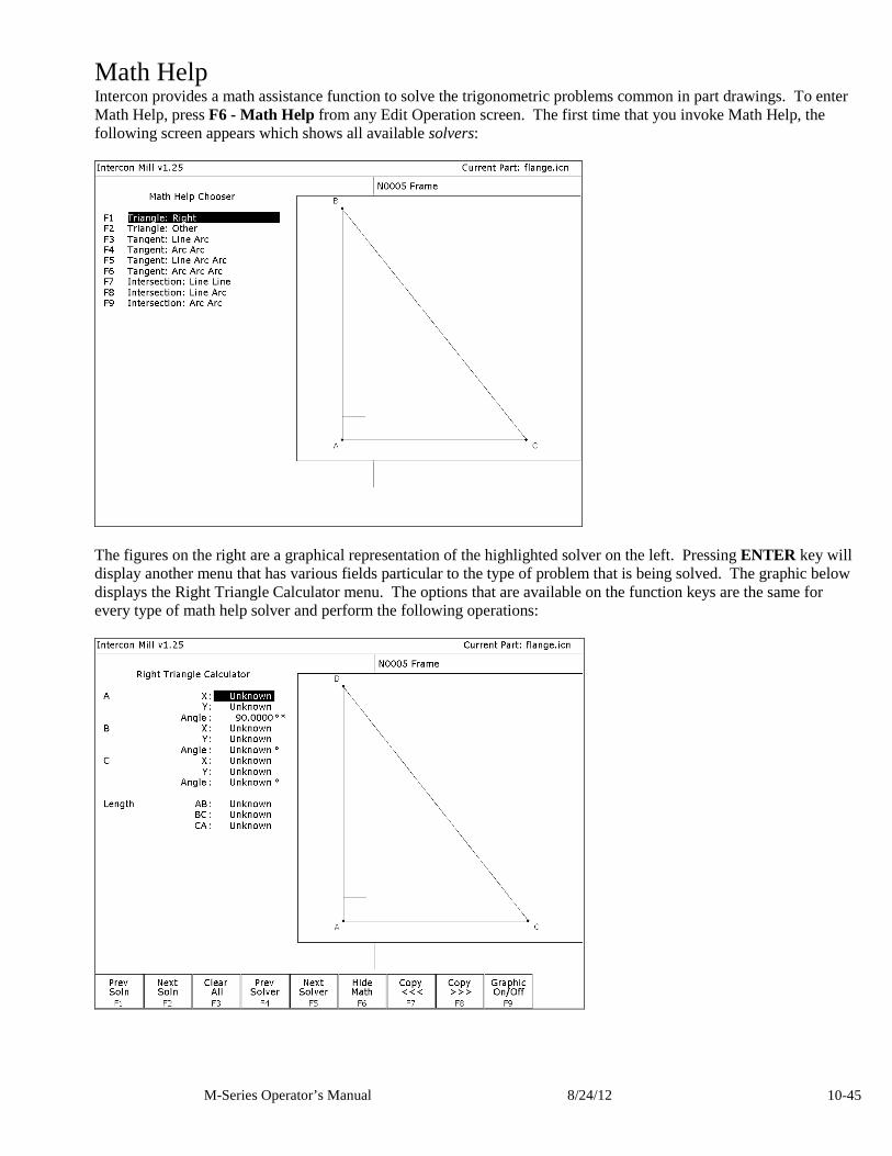
M-Series Operator’s Manual 8/24/12 10-45
Math Help Intercon provides a math assistance function to solve the trigonometric problems common in part drawings. To enter Math Help, press F6 - Math Help from any Edit Operation screen. The first time that you invoke Math Help, the following screen appears which shows all available solvers:
The figures on the right are a graphical representation of the highlighted solver on the left. Pressing ENTER key will display another menu that has various fields particular to the type of problem that is being solved. The graphic below displays the Right Triangle Calculator menu. The options that are available on the function keys are the same for every type of math help solver and perform the following operations:
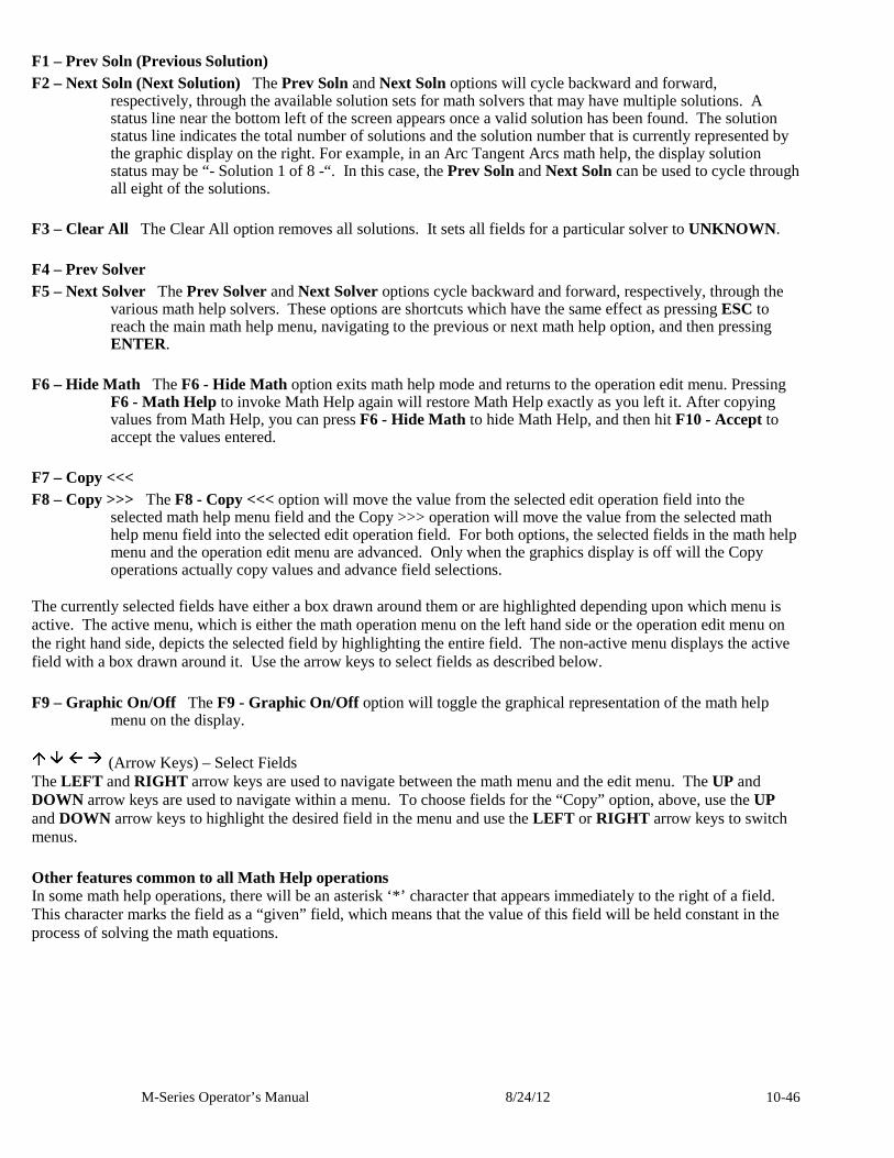
M-Series Operator’s Manual 8/24/12 10-46
F1 – Prev Soln (Previous Solution) F2 – Next Soln (Next Solution) The Prev Soln and Next Soln options will cycle backward and forward,
respectively, through the available solution sets for math solvers that may have multiple solutions. A status line near the bottom left of the screen appears once a valid solution has been found. The solution status line indicates the total number of solutions and the solution number that is currently represented by the graphic display on the right. For example, in an Arc Tangent Arcs math help, the display solution status may be “- Solution 1 of 8 -“. In this case, the Prev Soln and Next Soln can be used to cycle through all eight of the solutions.
F3 – Clear All The Clear All option removes all solutions. It sets all fields for a particular solver to UNKNOWN . F4 – Prev Solver F5 – Next Solver The Prev Solver and Next Solver options cycle backward and forward, respectively, through the
various math help solvers. These options are shortcuts which have the same effect as pressing ESC to reach the main math help menu, navigating to the previous or next math help option, and then pressing ENTER.
F6 – Hide Math The F6 - Hide Math option exits math help mode and returns to the operation edit menu. Pressing
F6 - Math Help to invoke Math Help again will restore Math Help exactly as you left it. After copying values from Math Help, you can press F6 - Hide Math to hide Math Help, and then hit F10 - Accept to accept the values entered.
F7 – Copy <<< F8 – Copy >>> The F8 - Copy <<< option will move the value from the selected edit operation field into the
selected math help menu field and the Copy >>> operation will move the value from the selected math help menu field into the selected edit operation field. For both options, the selected fields in the math help menu and the operation edit menu are advanced. Only when the graphics display is off will the Copy operations actually copy values and advance field selections.
The currently selected fields have either a box drawn around them or are highlighted depending upon which menu is active. The active menu, which is either the math operation menu on the left hand side or the operation edit menu on the right hand side, depicts the selected field by highlighting the entire field. The non-active menu displays the active field with a box drawn around it. Use the arrow keys to select fields as described below. F9 – Graphic On/Off The F9 - Graphic On/Off option will toggle the graphical representation of the math help
menu on the display.
(Arrow Keys) – Select Fields The LEFT and RIGHT arrow keys are used to navigate between the math menu and the edit menu. The UP and DOWN arrow keys are used to navigate within a menu. To choose fields for the “Copy” option, above, use the UP and DOWN arrow keys to highlight the desired field in the menu and use the LEFT or RIGHT arrow keys to switch menus. Other features common to all Math Help operations In some math help operations, there will be an asterisk ‘*’ character that appears immediately to the right of a field. This character marks the field as a “given” field, which means that the value of this field will be held constant in the process of solving the math equations.
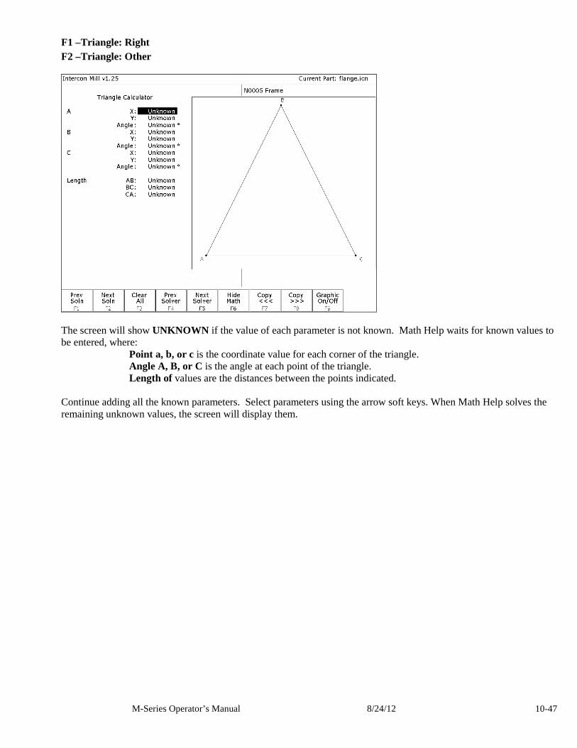
M-Series Operator’s Manual 8/24/12 10-47
F1 –Triangle: Right F2 –Triangle: Other
The screen will show UNKNOWN if the value of each parameter is not known. Math Help waits for known values to be entered, where: Point a, b, or c is the coordinate value for each corner of the triangle. Angle A, B, or C is the angle at each point of the triangle. Length of values are the distances between the points indicated. Continue adding all the known parameters. Select parameters using the arrow soft keys. When Math Help solves the remaining unknown values, the screen will display them.
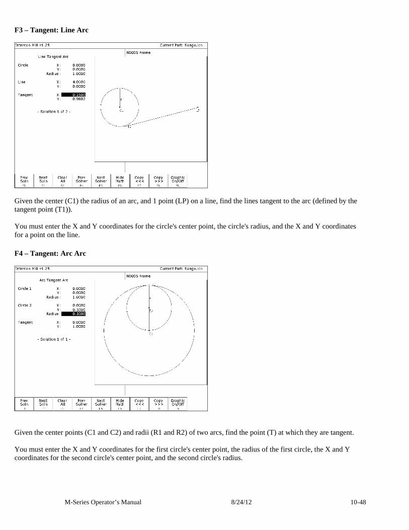
M-Series Operator’s Manual 8/24/12 10-48
F3 – Tangent: Line Arc
Given the center (C1) the radius of an arc, and 1 point (LP) on a line, find the lines tangent to the arc (defined by the tangent point (T1)). You must enter the X and Y coordinates for the circle's center point, the circle's radius, and the X and Y coordinates for a point on the line. F4 – Tangent: Arc Arc
Given the center points (C1 and C2) and radii (R1 and R2) of two arcs, find the point (T) at which they are tangent. You must enter the X and Y coordinates for the first circle's center point, the radius of the first circle, the X and Y coordinates for the second circle's center point, and the second circle's radius.
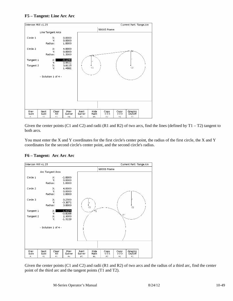
M-Series Operator’s Manual 8/24/12 10-49
F5 – Tangent: Line Arc Arc
Given the center points (C1 and C2) and radii (R1 and R2) of two arcs, find the lines (defined by T1 – T2) tangent to both arcs. You must enter the X and Y coordinates for the first circle's center point, the radius of the first circle, the X and Y coordinates for the second circle's center point, and the second circle's radius. F6 – Tangent: Arc Arc Arc
Given the center points (C1 and C2) and radii (R1 and R2) of two arcs and the radius of a third arc, find the center point of the third arc and the tangent points (T1 and T2).
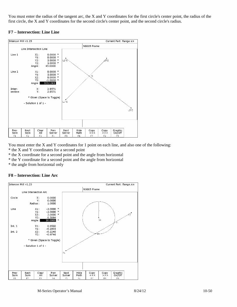
M-Series Operator’s Manual 8/24/12 10-50
You must enter the radius of the tangent arc, the X and Y coordinates for the first circle's center point, the radius of the first circle, the X and Y coordinates for the second circle's center point, and the second circle's radius. F7 – Intersection: Line Line
You must enter the X and Y coordinates for 1 point on each line, and also one of the following: * the X and Y coordinates for a second point * the X coordinate for a second point and the angle from horizontal * the Y coordinate for a second point and the angle from horizontal * the angle from horizontal only F8 – Intersection: Line Arc
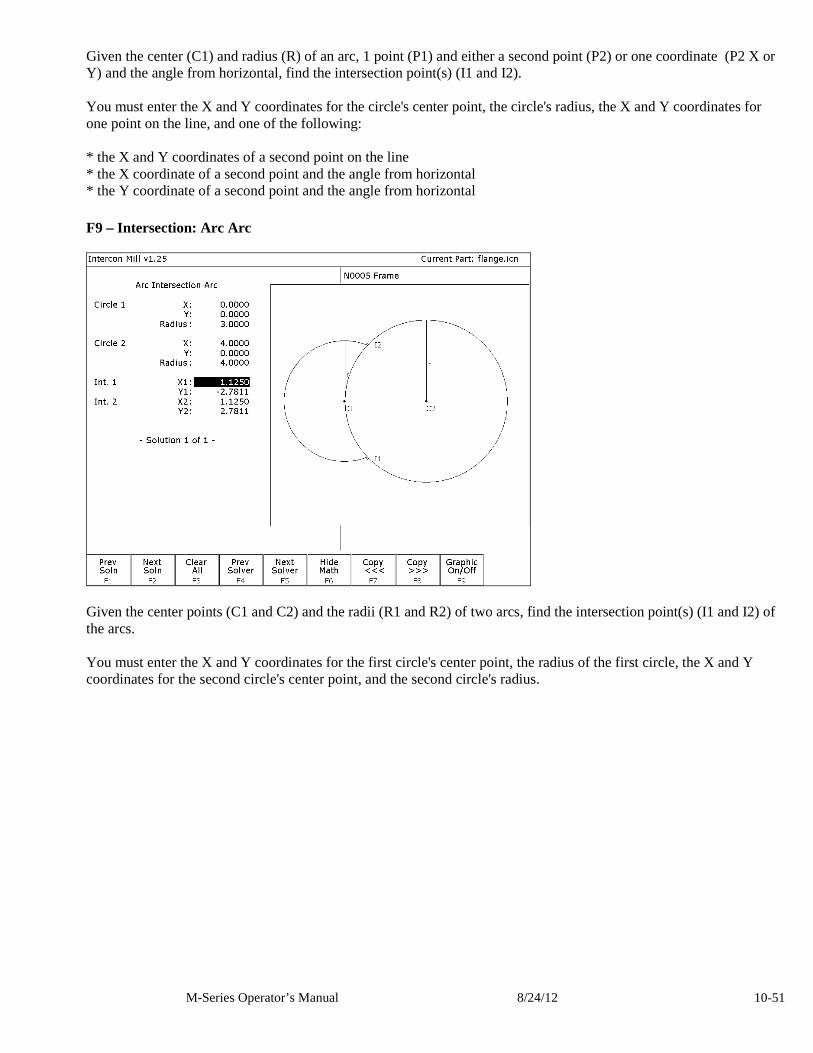
M-Series Operator’s Manual 8/24/12 10-51
Given the center (C1) and radius (R) of an arc, 1 point (P1) and either a second point (P2) or one coordinate (P2 X or Y) and the angle from horizontal, find the intersection point(s) (I1 and I2). You must enter the X and Y coordinates for the circle's center point, the circle's radius, the X and Y coordinates for one point on the line, and one of the following: * the X and Y coordinates of a second point on the line * the X coordinate of a second point and the angle from horizontal * the Y coordinate of a second point and the angle from horizontal F9 – Intersection: Arc Arc
Given the center points (C1 and C2) and the radii (R1 and R2) of two arcs, find the intersection point(s) (I1 and I2) of the arcs. You must enter the X and Y coordinates for the first circle's center point, the radius of the first circle, the X and Y coordinates for the second circle's center point, and the second circle's radius.
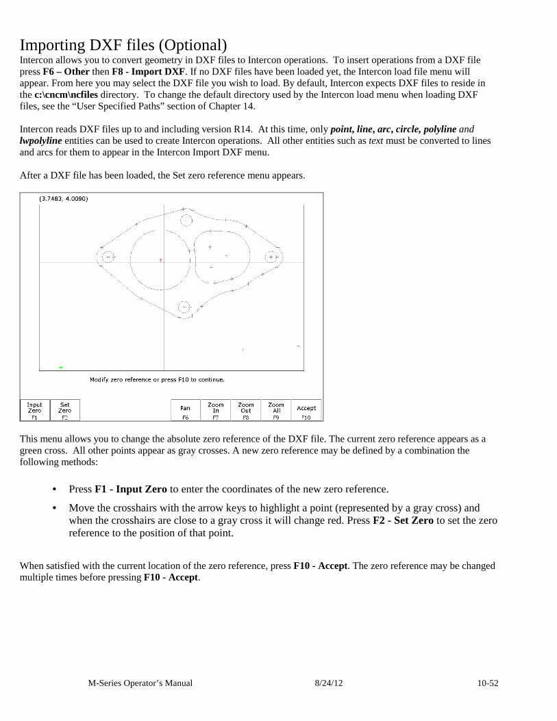
M-Series Operator’s Manual 8/24/12 10-52
Importing DXF files (Optional) Intercon allows you to convert geometry in DXF files to Intercon operations. To insert operations from a DXF file press F6 – Other then F8 - Import DXF . If no DXF files have been loaded yet, the Intercon load file menu will appear. From here you may select the DXF file you wish to load. By default, Intercon expects DXF files to reside in the c:\cncm\ncfiles directory. To change the default directory used by the Intercon load menu when loading DXF files, see the “User Specified Paths” section of Chapter 14. Intercon reads DXF files up to and including version R14. At this time, only point, line, arc, circle, polyline and lwpolyline entities can be used to create Intercon operations. All other entities such as text must be converted to lines and arcs for them to appear in the Intercon Import DXF menu. After a DXF file has been loaded, the Set zero reference menu appears.
This menu allows you to change the absolute zero reference of the DXF file. The current zero reference appears as a green cross. All other points appear as gray crosses. A new zero reference may be defined by a combination the following methods:
• Press F1 - Input Zero to enter the coordinates of the new zero reference.
• Move the crosshairs with the arrow keys to highlight a point (represented by a gray cross) and when the crosshairs are close to a gray cross it will change red. Press F2 - Set Zero to set the zero reference to the position of that point.
When satisfied with the current location of the zero reference, press F10 - Accept. The zero reference may be changed multiple times before pressing F10 - Accept.
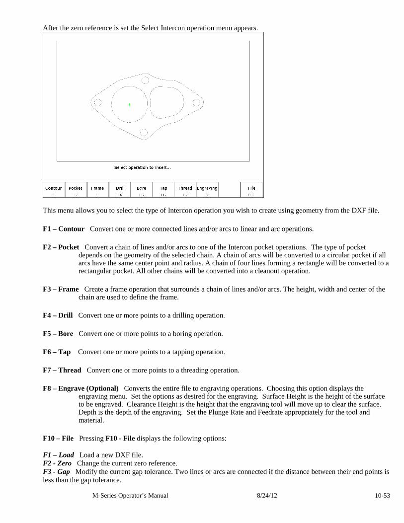
M-Series Operator’s Manual 8/24/12 10-53
After the zero reference is set the Select Intercon operation menu appears.
This menu allows you to select the type of Intercon operation you wish to create using geometry from the DXF file. F1 – Contour Convert one or more connected lines and/or arcs to linear and arc operations. F2 – Pocket Convert a chain of lines and/or arcs to one of the Intercon pocket operations. The type of pocket
depends on the geometry of the selected chain. A chain of arcs will be converted to a circular pocket if all arcs have the same center point and radius. A chain of four lines forming a rectangle will be converted to a rectangular pocket. All other chains will be converted into a cleanout operation.
F3 – Frame Create a frame operation that surrounds a chain of lines and/or arcs. The height, width and center of the
chain are used to define the frame. F4 – Drill Convert one or more points to a drilling operation. F5 – Bore Convert one or more points to a boring operation. F6 – Tap Convert one or more points to a tapping operation. F7 – Thread Convert one or more points to a threading operation. F8 – Engrave (Optional) Converts the entire file to engraving operations. Choosing this option displays the
engraving menu. Set the options as desired for the engraving. Surface Height is the height of the surface to be engraved. Clearance Height is the height that the engraving tool will move up to clear the surface. Depth is the depth of the engraving. Set the Plunge Rate and Feedrate appropriately for the tool and material.
F10 – File Pressing F10 - File displays the following options: F1 – Load Load a new DXF file. F2 - Zero Change the current zero reference. F3 - Gap Modify the current gap tolerance. Two lines or arcs are connected if the distance between their end points is less than the gap tolerance.
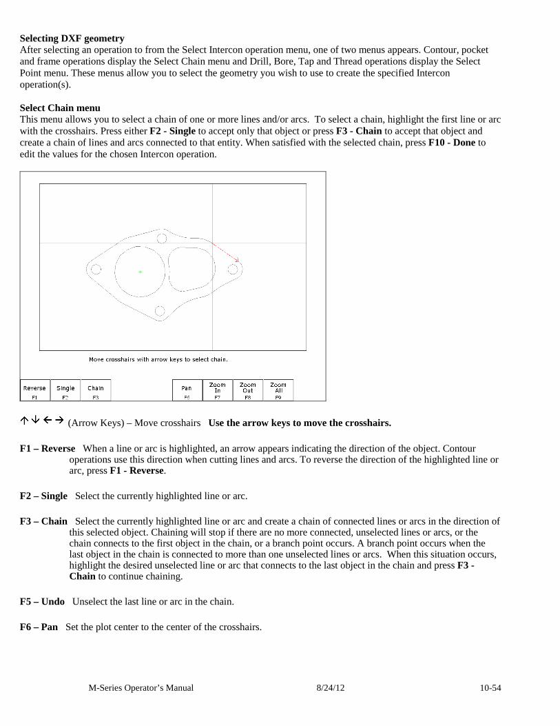
M-Series Operator’s Manual 8/24/12 10-54
Selecting DXF geometry After selecting an operation to from the Select Intercon operation menu, one of two menus appears. Contour, pocket and frame operations display the Select Chain menu and Drill, Bore, Tap and Thread operations display the Select Point menu. These menus allow you to select the geometry you wish to use to create the specified Intercon operation(s). Select Chain menu This menu allows you to select a chain of one or more lines and/or arcs. To select a chain, highlight the first line or arc with the crosshairs. Press either F2 - Single to accept only that object or press F3 - Chain to accept that object and create a chain of lines and arcs connected to that entity. When satisfied with the selected chain, press F10 - Done to edit the values for the chosen Intercon operation.
(Arrow Keys) – Move crosshairs Use the arrow keys to move the crosshairs. F1 – Reverse When a line or arc is highlighted, an arrow appears indicating the direction of the object. Contour
operations use this direction when cutting lines and arcs. To reverse the direction of the highlighted line or arc, press F1 - Reverse.
F2 – Single Select the currently highlighted line or arc. F3 – Chain Select the currently highlighted line or arc and create a chain of connected lines or arcs in the direction of
this selected object. Chaining will stop if there are no more connected, unselected lines or arcs, or the chain connects to the first object in the chain, or a branch point occurs. A branch point occurs when the last object in the chain is connected to more than one unselected lines or arcs. When this situation occurs, highlight the desired unselected line or arc that connects to the last object in the chain and press F3 - Chain to continue chaining.
F5 – Undo Unselect the last line or arc in the chain. F6 – Pan Set the plot center to the center of the crosshairs.
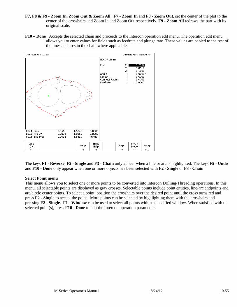
M-Series Operator’s Manual 8/24/12 10-55
F7, F8 & F9 - Zoom In, Zoom Out & Zoom All F7 - Zoom In and F8 - Zoom Out, set the center of the plot to the center of the crosshairs and Zoom In and Zoom Out respectively. F9 - Zoom All redraws the part with its original scale.
F10 – Done Accepts the selected chain and proceeds to the Intercon operation edit menu. The operation edit menu
allows you to enter values for fields such as feedrate and plunge rate. These values are copied to the rest of the lines and arcs in the chain where applicable.
The keys F1 - Reverse, F2 - Single and F3 - Chain only appear when a line or arc is highlighted. The keys F5 - Undo and F10 - Done only appear when one or more objects has been selected with F2 - Single or F3 - Chain. Select Point menu This menu allows you to select one or more points to be converted into Intercon Drilling/Threading operations. In this menu, all selectable points are displayed as gray crosses. Selectable points include point entities, line/arc endpoints and arc/circle center points. To select a point, position the crosshairs over the desired point until the cross turns red and press F2 - Single to accept the point. More points can be selected by highlighting them with the crosshairs and pressing F2 - Single. F1 - Window can be used to select all points within a specified window. When satisfied with the selected point(s), press F10 - Done to edit the Intercon operation parameters.
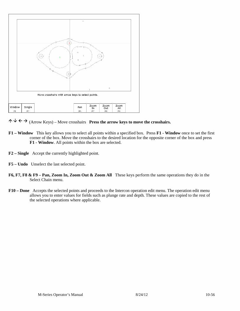
M-Series Operator’s Manual 8/24/12 10-56
(Arrow Keys) – Move crosshairs Press the arrow keys to move the crosshairs. F1 – Window This key allows you to select all points within a specified box. Press F1 - Window once to set the first
corner of the box. Move the crosshairs to the desired location for the opposite corner of the box and press F1 - Window. All points within the box are selected.
F2 – Single Accept the currently highlighted point. F5 – Undo Unselect the last selected point. F6, F7, F8 & F9 – Pan, Zoom In, Zoom Out & Zoom All These keys perform the same operations they do in the
Select Chain menu. F10 – Done Accepts the selected points and proceeds to the Intercon operation edit menu. The operation edit menu
allows you to enter values for fields such as plunge rate and depth. These values are copied to the rest of the selected operations where applicable.
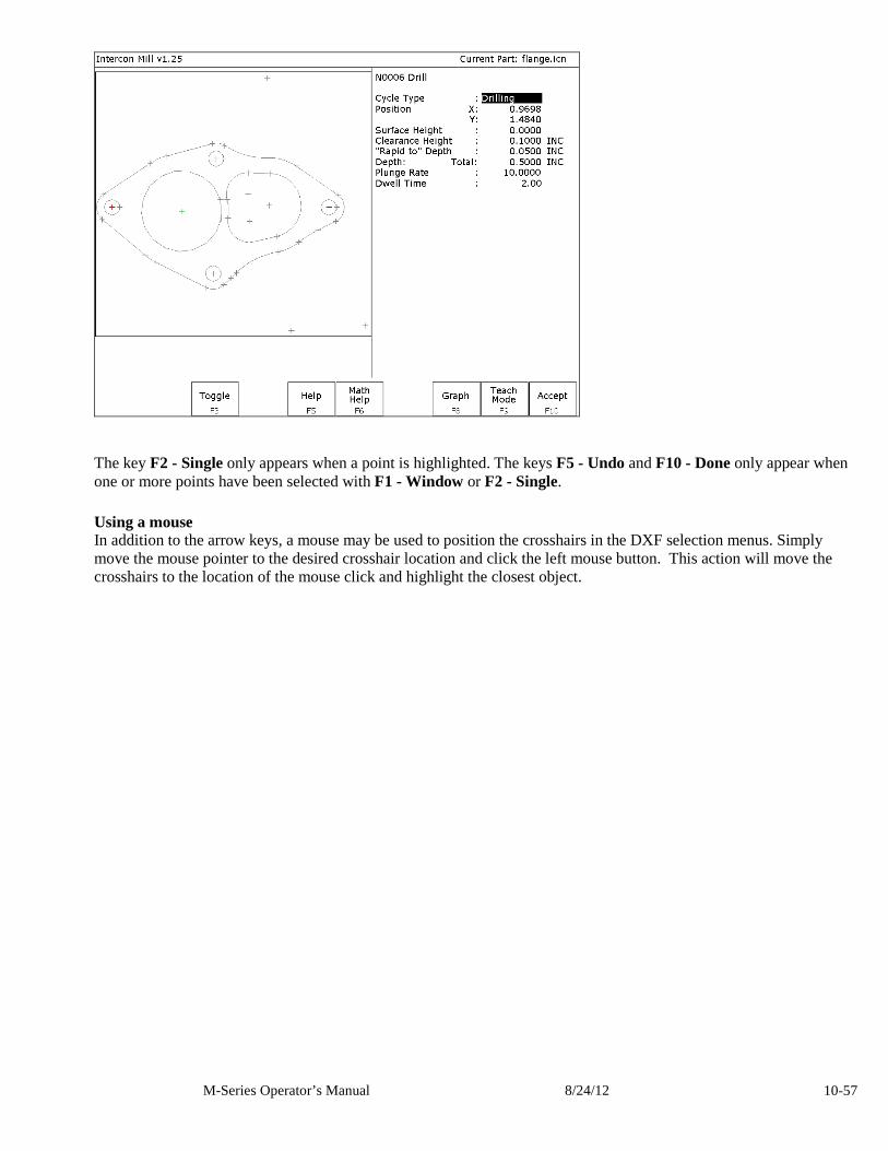
M-Series Operator’s Manual 8/24/12 10-57
The key F2 - Single only appears when a point is highlighted. The keys F5 - Undo and F10 - Done only appear when one or more points have been selected with F1 - Window or F2 - Single. Using a mouse In addition to the arrow keys, a mouse may be used to position the crosshairs in the DXF selection menus. Simply move the mouse pointer to the desired crosshair location and click the left mouse button. This action will move the crosshairs to the location of the mouse click and highlight the closest object.

M-Series Operator’s Manual 8/24/12 10-58
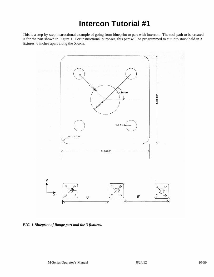
M-Series Operator’s Manual 8/24/12 10-59
Intercon Tutorial #1 This is a step-by-step instructional example of going from blueprint to part with Intercon. The tool path to be created is for the part shown in Figure 1. For instructional purposes, this part will be programmed to cut into stock held in 3 fixtures, 6 inches apart along the X-axis.
FIG. 1 Blueprint of flange part and the 3 fixtures.
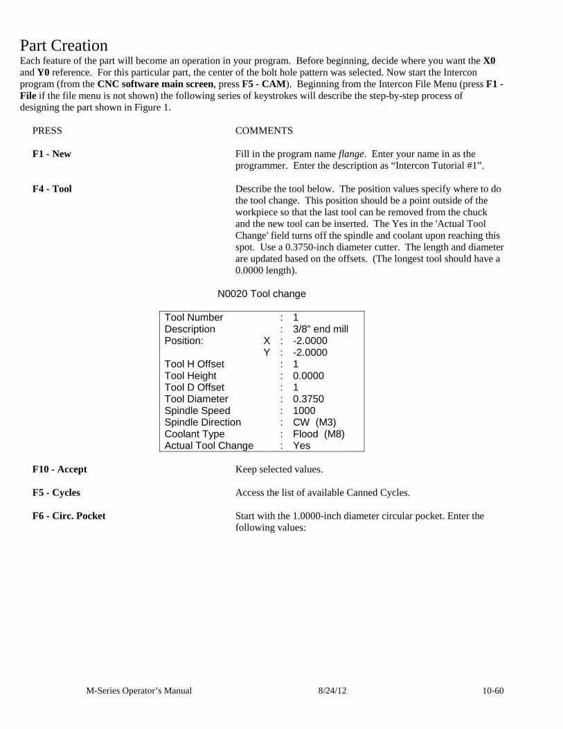
M-Series Operator’s Manual 8/24/12 10-60
Part Creation Each feature of the part will become an operation in your program. Before beginning, decide where you want the X0 and Y0 reference. For this particular part, the center of the bolt hole pattern was selected. Now start the Intercon program (from the CNC software main screen, press F5 - CAM ). Beginning from the Intercon File Menu (press F1 - File if the file menu is not shown) the following series of keystrokes will describe the step-by-step process of designing the part shown in Figure 1.
PRESS COMMENTS F1 - New Fill in the program name flange. Enter your name in as the
programmer. Enter the description as “Intercon Tutorial #1”. F4 - Tool Describe the tool below. The position values specify where to do
the tool change. This position should be a point outside of the workpiece so that the last tool can be removed from the chuck and the new tool can be inserted. The Yes in the 'Actual Tool Change' field turns off the spindle and coolant upon reaching this spot. Use a 0.3750-inch diameter cutter. The length and diameter are updated based on the offsets. (The longest tool should have a 0.0000 length).
N0020 Tool change
Tool Number : 1 Description : 3/8" end mill Position: X : -2.0000 Y : -2.0000 Tool H Offset : 1 Tool Height : 0.0000 Tool D Offset : 1 Tool Diameter : 0.3750 Spindle Speed : 1000 Spindle Direction : CW (M3) Coolant Type : Flood (M8) Actual Tool Change : Yes
F10 - Accept Keep selected values. F5 - Cycles Access the list of available Canned Cycles. F6 - Circ. Pocket Start with the 1.0000-inch diameter circular pocket. Enter the
following values:
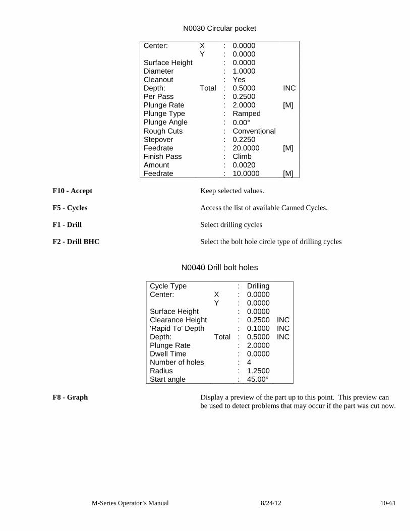
M-Series Operator’s Manual 8/24/12 10-61
N0030 Circular pocket
Center: X : 0.0000 Y : 0.0000 Surface Height : 0.0000 Diameter : 1.0000 Cleanout : Yes Depth: Total : 0.5000 INC Per Pass : 0.2500 Plunge Rate : 2.0000 [M] Plunge Type : Ramped Plunge Angle : 0.00° Rough Cuts : Conventional Stepover : 0.2250 Feedrate : 20.0000 [M] Finish Pass : Climb Amount : 0.0020 Feedrate : 10.0000 [M]
F10 - Accept Keep selected values. F5 - Cycles Access the list of available Canned Cycles. F1 - Drill Select drilling cycles F2 - Drill BHC Select the bolt hole circle type of drilling cycles
N0040 Drill bolt holes
Cycle Type : Drilling Center: X : 0.0000 Y : 0.0000 Surface Height : 0.0000 Clearance Height : 0.2500 INC 'Rapid To' Depth : 0.1000 INC Depth: Total : 0.5000 INC Plunge Rate : 2.0000 Dwell Time : 0.0000 Number of holes : 4 Radius : 1.2500 Start angle : 45.00°
F8 - Graph Display a preview of the part up to this point. This preview can
be used to detect problems that may occur if the part was cut now.
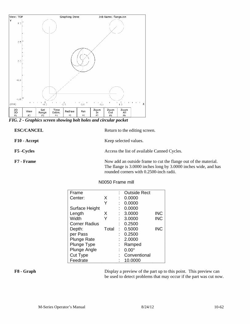
M-Series Operator’s Manual 8/24/12 10-62
FIG. 2 - Graphics screen showing bolt holes and circular pocket
ESC/CANCEL Return to the editing screen. F10 - Accept Keep selected values. F5 -Cycles Access the list of available Canned Cycles. F7 - Frame Now add an outside frame to cut the flange out of the material.
The flange is 3.0000 inches long by 3.0000 inches wide, and has rounded corners with 0.2500-inch radii.
N0050 Frame mill
Frame : Outside Rect Center: X : 0.0000 Y : 0.0000 Surface Height : 0.0000 Length X : 3.0000 INC Width Y : 3.0000 INC Corner Radius : 0.2500 Depth: Total : 0.5000 INC per Pass : 0.2500 Plunge Rate : 2.0000 Plunge Type : Ramped Plunge Angle : 0.00° Cut Type : Conventional Feedrate : 10.0000
F8 - Graph Display a preview of the part up to this point. This preview can
be used to detect problems that may occur if the part was cut now.
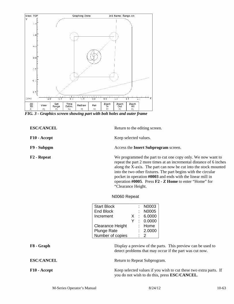
M-Series Operator’s Manual 8/24/12 10-63
FIG. 3 - Graphics screen showing part with bolt holes and outer frame
ESC/CANCEL Return to the editing screen. F10 - Accept Keep selected values. F9 - Subpgm Access the Insert Subprogram screen. F2 - Repeat We programmed the part to cut one copy only. We now want to
repeat the part 2 more times at an incremental distance of 6 inches along the X-axis. The part can now be cut into the stock mounted into the two other fixtures. The part begins with the circular pocket in operation #0003 and ends with the linear mill in operation #0005. Press F2 - Z Home to enter “Home” for “Clearance Height.
N0060 Repeat
Start Block : N0003 End Block : N0005 Increment X : 6.0000 Y : 0.0000 Clearance Height : Home Plunge Rate : 2.0000 Number of copies : 2
F8 - Graph Display a preview of the parts. This preview can be used to
detect problems that may occur if the part was cut now. ESC/CANCEL Return to Repeat Subprogram. F10 - Accept Keep selected values if you wish to cut these two extra parts. If
you do not wish to do this, press ESC/CANCEL .
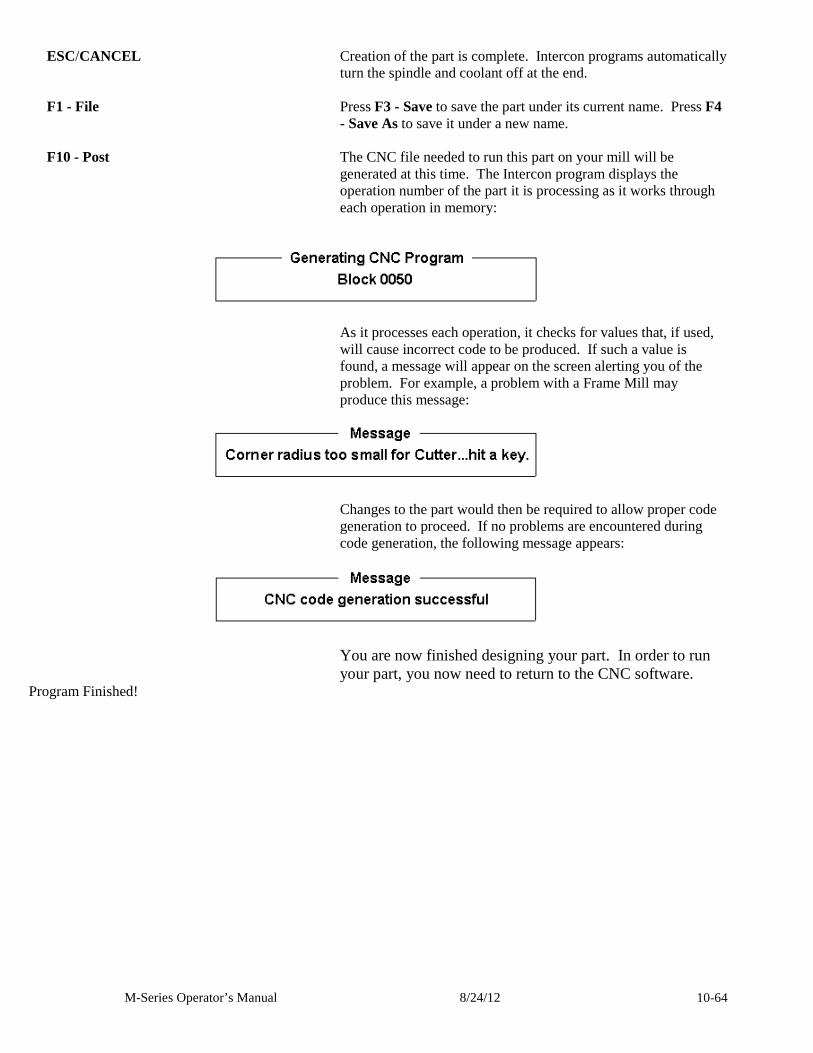
M-Series Operator’s Manual 8/24/12 10-64
ESC/CANCEL Creation of the part is complete. Intercon programs automatically turn the spindle and coolant off at the end.
F1 - File Press F3 - Save to save the part under its current name. Press F4
- Save As to save it under a new name. F10 - Post The CNC file needed to run this part on your mill will be
generated at this time. The Intercon program displays the operation number of the part it is processing as it works through each operation in memory:
As it processes each operation, it checks for values that, if used, will cause incorrect code to be produced. If such a value is found, a message will appear on the screen alerting you of the problem. For example, a problem with a Frame Mill may produce this message:
Changes to the part would then be required to allow proper code generation to proceed. If no problems are encountered during code generation, the following message appears:
You are now finished designing your part. In order to run your part, you now need to return to the CNC software.
Program Finished!
M-Series Operator’s Manual 8/24/12 10-65
Milling the Part Now that the part has been programmed, it is time to mill it. Take your material and clamp it to the table. Remember that the clamps must be positioned such that they do not interfere with the tool as it cuts. You may choose either to place the clamps around the edges of the material for the entire process and let the part drop through upon completion, or you may wish to pause after milling the circular pockets and place clamps through the holes to prevent the part from moving. The second option decreases the chance of the part being marred because it moved during milling. Now you need to set your XYZ reference points. Insert your longest tool in the quill and follow the procedure listed below: PRESS COMMENTS JOG KEYS Jog the table so that your tool rests on the stock at the location
that will represent X0 and Y0. F1 - Setup Enter the CNC software Setup screen. We are going to establish
the part XYZ zero at the current tool location.
F1 - Part Access the Part Setup options.
F10 - Set Set your X zero position at current tool location. F1 - Next Axis Select the Y-axis next. F10 - Set Set your Y zero position at current tool location. F1 - Next Axis Select the Z-axis next. F10 - Set Set your Z zero position at current tool location. TOOL CHECK Moves the quill to the Z home position if the home position has been set. Moves tool to Z+ limit switch and sets home
position if not. ESC/CANCEL Leave Part Setup screen. F2 - Tool Access Tool Library Editor. This is the place where we want to
measure the actual heights of our tools (since we could not set the actual values in Intercon).
F1 - Offset Lib. You need to make sure that the tool diameter and height offset
values are the correct ones for the tools you are going to be using. Inspect the values for D001 and H001. D001 should be 0.375, H1 should be 0.0000 (the two inch tool). If either of these values are incorrect, use the arrow keys to select the incorrect values. Enter the new values in their places and press ENTER to accept them. NOTE: The tool heights used above are merely example heights. In order to accurately measure the heights of your tools, see the description of measuring tool heights in Chapter 5.
F10 - Save Keep the updated tool offset library values.
M-Series Operator’s Manual 8/24/12 10-66
F2 - Tool Lib. Now you need to make sure that each tool uses the correct diameter and height offset values. Inspect the values for T001. T1 should use H001 and D001. If any of these values are incorrect, use the arrow keys to select the incorrect values. Enter the new values in their places and press ENTER to accept them. You may also select spindle and coolant settings for your tools here, or enter a short description of the tool.
F10 - Save Keep the updated Tool Library values. ESC/CANCEL Leave Tool Setup. Return to the CNC software Setup Screen. ESC/CANCEL Leave CNC software Setup. Return to the CNC software Main
Screen. CYCLE START The CYCLE START button is located on your jog panel. This
key will cause the mill to begin cutting your part
Tutorial Complete!
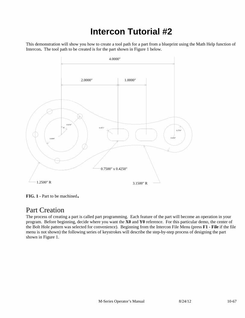
M-Series Operator’s Manual 8/24/12 10-67
Intercon Tutorial #2 This demonstration will show you how to create a tool path for a part from a blueprint using the Math Help function of Intercon. The tool path to be created is for the part shown in Figure 1 below.
FIG. 1 - Part to be machined.
Part Creation The process of creating a part is called part programming. Each feature of the part will become an operation in your program. Before beginning, decide where you want the X0 and Y0 reference. For this particular demo, the center of the Bolt Hole pattern was selected for convenience). Beginning from the Intercon File Menu (press F1 - File if the file menu is not shown) the following series of keystrokes will describe the step-by-step process of designing the part shown in Figure 1.
0.1875" 0.3750"
0.6250" 0.6000"
0.9250"
4.0000"
2.0000" 1.0000"
45
0.7500" x 0.4250"
3.1500" R 1.2500" R
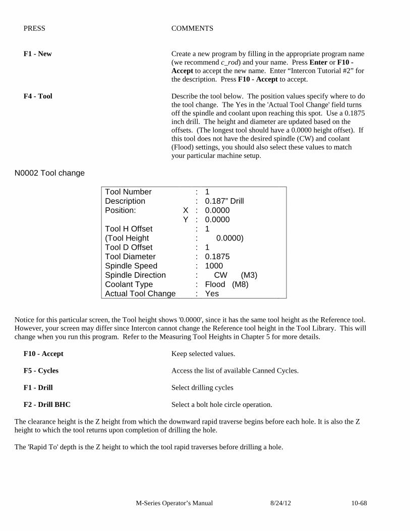
M-Series Operator’s Manual 8/24/12 10-68
PRESS COMMENTS F1 - New Create a new program by filling in the appropriate program name
(we recommend c_rod) and your name. Press Enter or F10 - Accept to accept the new name. Enter “Intercon Tutorial #2” for the description. Press F10 - Accept to accept.
F4 - Tool Describe the tool below. The position values specify where to do
the tool change. The Yes in the 'Actual Tool Change' field turns off the spindle and coolant upon reaching this spot. Use a 0.1875 inch drill. The height and diameter are updated based on the offsets. (The longest tool should have a 0.0000 height offset). If this tool does not have the desired spindle (CW) and coolant (Flood) settings, you should also select these values to match your particular machine setup.
N0002 Tool change
Tool Number : 1 Description : 0.187” Drill Position: X : 0.0000 Y : 0.0000 Tool H Offset : 1 (Tool Height : 0.0000) Tool D Offset : 1 Tool Diameter : 0.1875 Spindle Speed : 1000 Spindle Direction : CW (M3) Coolant Type : Flood (M8) Actual Tool Change : Yes
Notice for this particular screen, the Tool height shows '0.0000', since it has the same tool height as the Reference tool. However, your screen may differ since Intercon cannot change the Reference tool height in the Tool Library. This will change when you run this program. Refer to the Measuring Tool Heights in Chapter 5 for more details.
F10 - Accept Keep selected values. F5 - Cycles Access the list of available Canned Cycles. F1 - Drill Select drilling cycles F2 - Drill BHC Select a bolt hole circle operation.
The clearance height is the Z height from which the downward rapid traverse begins before each hole. It is also the Z height to which the tool returns upon completion of drilling the hole. The 'Rapid To' depth is the Z height to which the tool rapid traverses before drilling a hole.
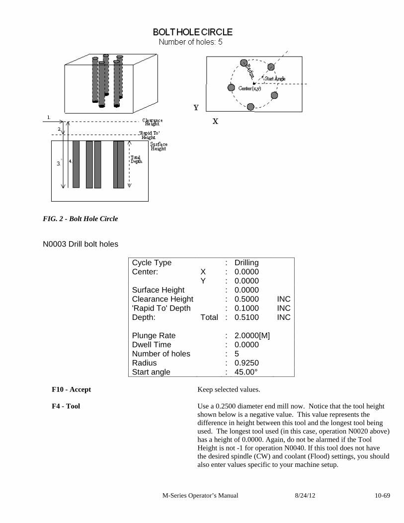
M-Series Operator’s Manual 8/24/12 10-69
FIG. 2 - Bolt Hole Circle N0003 Drill bolt holes
Cycle Type : Drilling Center: X : 0.0000 Y : 0.0000 Surface Height : 0.0000 Clearance Height : 0.5000 INC 'Rapid To' Depth : 0.1000 INC Depth: Total : 0.5100 INC Plunge Rate : 2.0000[M] Dwell Time : 0.0000 Number of holes : 5 Radius : 0.9250 Start angle : 45.00°
F10 - Accept Keep selected values. F4 - Tool Use a 0.2500 diameter end mill now. Notice that the tool height
shown below is a negative value. This value represents the difference in height between this tool and the longest tool being used. The longest tool used (in this case, operation N0020 above) has a height of 0.0000. Again, do not be alarmed if the Tool Height is not -1 for operation N0040. If this tool does not have the desired spindle (CW) and coolant (Flood) settings, you should also enter values specific to your machine setup.
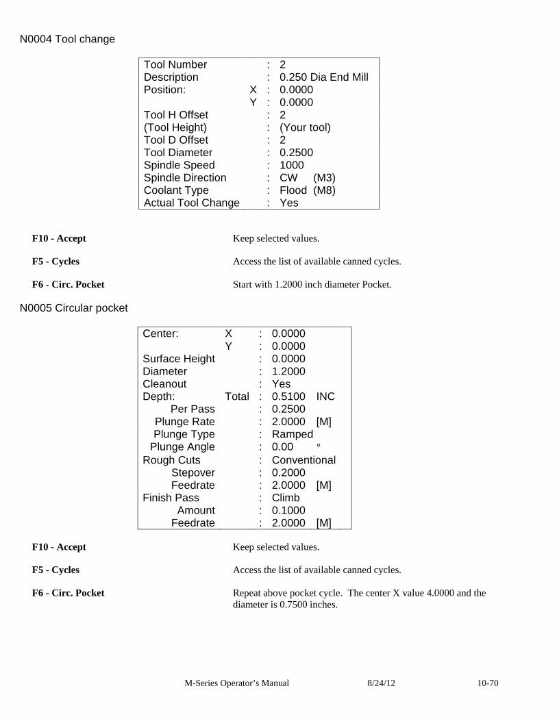
M-Series Operator’s Manual 8/24/12 10-70
N0004 Tool change
Tool Number : 2 Description : 0.250 Dia End Mill Position: X : 0.0000 Y : 0.0000 Tool H Offset : 2 (Tool Height) : (Your tool) Tool D Offset : 2 Tool Diameter : 0.2500 Spindle Speed : 1000 Spindle Direction : CW (M3) Coolant Type : Flood (M8) Actual Tool Change : Yes
F10 - Accept Keep selected values. F5 - Cycles Access the list of available canned cycles. F6 - Circ. Pocket Start with 1.2000 inch diameter Pocket.
N0005 Circular pocket
Center: X : 0.0000 Y : 0.0000 Surface Height : 0.0000 Diameter : 1.2000 Cleanout : Yes Depth: Total : 0.5100 INC
Per Pass : 0.2500 Plunge Rate : 2.0000 [M] Plunge Type : Ramped
Plunge Angle : 0.00 ° Rough Cuts : Conventional
Stepover : 0.2000 Feedrate : 2.0000 [M]
Finish Pass : Climb Amount : 0.1000
Feedrate : 2.0000 [M] F10 - Accept Keep selected values. F5 - Cycles Access the list of available canned cycles. F6 - Circ. Pocket Repeat above pocket cycle. The center X value 4.0000 and the
diameter is 0.7500 inches.
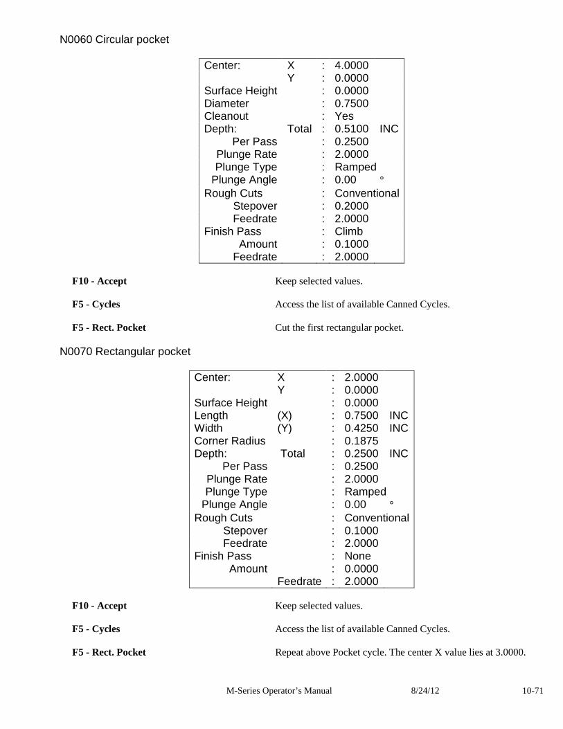
M-Series Operator’s Manual 8/24/12 10-71
N0060 Circular pocket
Center: X : 4.0000 Y : 0.0000 Surface Height : 0.0000 Diameter : 0.7500 Cleanout : Yes Depth: Total : 0.5100 INC
Per Pass : 0.2500 Plunge Rate : 2.0000 Plunge Type : Ramped
Plunge Angle : 0.00 ° Rough Cuts : Conventional
Stepover : 0.2000 Feedrate : 2.0000
Finish Pass : Climb Amount : 0.1000
Feedrate : 2.0000
F10 - Accept Keep selected values. F5 - Cycles Access the list of available Canned Cycles. F5 - Rect. Pocket Cut the first rectangular pocket.
N0070 Rectangular pocket
Center: X : 2.0000 Y : 0.0000 Surface Height : 0.0000 Length (X) : 0.7500 INC Width (Y) : 0.4250 INC Corner Radius : 0.1875 Depth: Total : 0.2500 INC
Per Pass : 0.2500 Plunge Rate : 2.0000 Plunge Type : Ramped
Plunge Angle : 0.00 ° Rough Cuts : Conventional
Stepover : 0.1000 Feedrate : 2.0000
Finish Pass : None Amount : 0.0000
Feedrate : 2.0000 F10 - Accept Keep selected values. F5 - Cycles Access the list of available Canned Cycles. F5 - Rect. Pocket Repeat above Pocket cycle. The center X value lies at 3.0000.
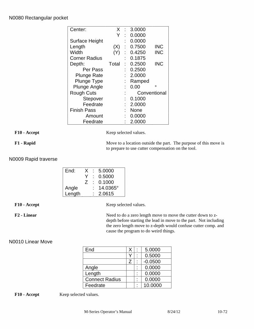
M-Series Operator’s Manual 8/24/12 10-72
N0080 Rectangular pocket
Center: X : 3.0000 Y : 0.0000 Surface Height : 0.0000 Length (X) : 0.7500 INC Width (Y) : 0.4250 INC Corner Radius : 0.1875 Depth: Total : 0.2500 INC
Per Pass : 0.2500 Plunge Rate : 2.0000 Plunge Type : Ramped
Plunge Angle : 0.00 ° Rough Cuts : Conventional
Stepover : 0.1000 Feedrate : 2.0000
Finish Pass : None Amount : 0.0000
Feedrate : 2.0000
F10 - Accept Keep selected values.
F1 - Rapid Move to a location outside the part. The purpose of this move is to prepare to use cutter compensation on the tool.
N0009 Rapid traverse
End: X : 5.0000 Y : 0.5000 Z : 0.1000 Angle : 14.0365° Length : 2.0615
F10 - Accept Keep selected values. F2 - Linear Need to do a zero length move to move the cutter down to z-
depth before starting the lead in move to the part. Not including the zero length move to z-depth would confuse cutter comp. and cause the program to do weird things.
N0010 Linear Move
F10 - Accept Keep selected values.
End X : 5.0000 Y : 0.5000 Z : -0.0500 Angle : 0.0000 Length : 0.0000 Connect Radius : 0.0000 Feedrate : 10.0000
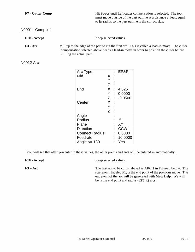
M-Series Operator’s Manual 8/24/12 10-73
F7 - Cutter Comp Hit Space until Left cutter compensation is selected. The tool must move outside of the part outline at a distance at least equal to its radius so the part outline is the correct size.
N00011 Comp left
F10 - Accept Keep selected values. F3 - Arc Mill up to the edge of the part to cut the first arc. This is called a lead-in move. The cutter
compensation selected above needs a lead-in move in order to position the cutter before milling the actual part.
N0012 Arc
You will see that after you enter in these values, the other points and arcs will be entered in automatically. F10 - Accept Keep selected values. F3 – Arc The first arc to be cut is labeled as ARC 1 in Figure 3 below. The
start point, labeled P1, is the end point of the previous move. The end point of the arc will be generated with Math Help. We will be using end point and radius (EP&R) arcs.
Arc Type: : EP&R Mid X : Y : Z : End X : 4.625 Y : 0.0000 Z : -0.0500 Center: X : Y : Z : Angle : Radius : .5 Plane : XY Direction : CCW Connect Radius : 0.0000 Feedrate : 10.0000 Angle <= 180 : Yes
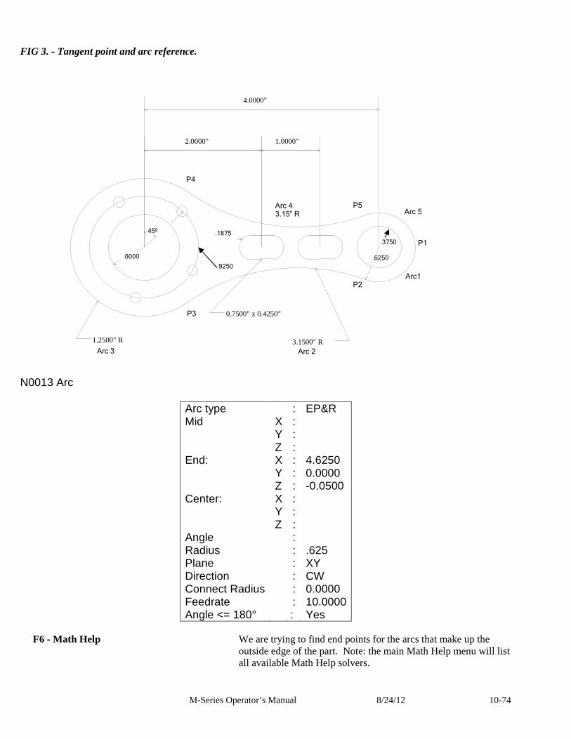
M-Series Operator’s Manual 8/24/12 10-74
4.0000"
2.0000" 1.0000"
45º
0.7500" x 0.4250"
3.1500" R 1.2500" R
.1875
.9250
.6000 .6250
.3750
Arc 2 Arc 3
Arc 4 3.15” R
P2
P3
P4
P5
Arc1
Arc 5
FIG 3. - Tangent point and arc reference. N0013 Arc
Arc type : EP&R Mid X : Y : Z : End: X : 4.6250 Y : 0.0000 Z : -0.0500 Center: X : Y : Z : Angle : Radius : .625 Plane : XY Direction : CW Connect Radius : 0.0000 Feedrate : 10.0000 Angle <= 180° : Yes
F6 - Math Help We are trying to find end points for the arcs that make up the
outside edge of the part. Note: the main Math Help menu will list all available Math Help solvers.
P1
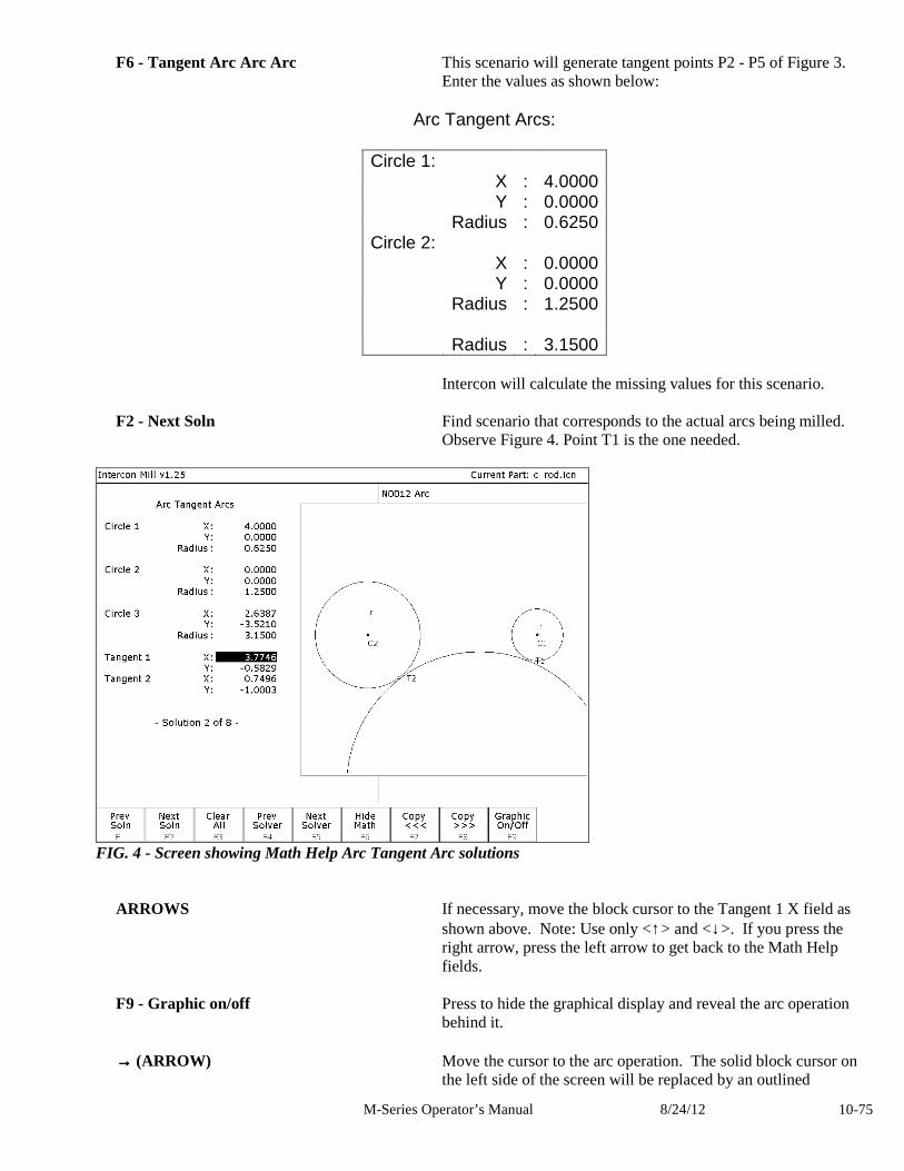
M-Series Operator’s Manual 8/24/12 10-75
F6 - Tangent Arc Arc Arc This scenario will generate tangent points P2 - P5 of Figure 3. Enter the values as shown below:
Arc Tangent Arcs:
Circle 1: X : 4.0000 Y : 0.0000 Radius : 0.6250 Circle 2: X : 0.0000 Y : 0.0000 Radius : 1.2500 Radius : 3.1500
Intercon will calculate the missing values for this scenario. F2 - Next Soln Find scenario that corresponds to the actual arcs being milled.
Observe Figure 4. Point T1 is the one needed.
FIG. 4 - Screen showing Math Help Arc Tangent Arc solutions
ARROWS If necessary, move the block cursor to the Tangent 1 X field as shown above. Note: Use only <↑> and <↓>. If you press the right arrow, press the left arrow to get back to the Math Help fields.
F9 - Graphic on/off Press to hide the graphical display and reveal the arc operation
behind it. →→→→ (ARROW) Move the cursor to the arc operation. The solid block cursor on
the left side of the screen will be replaced by an outlined
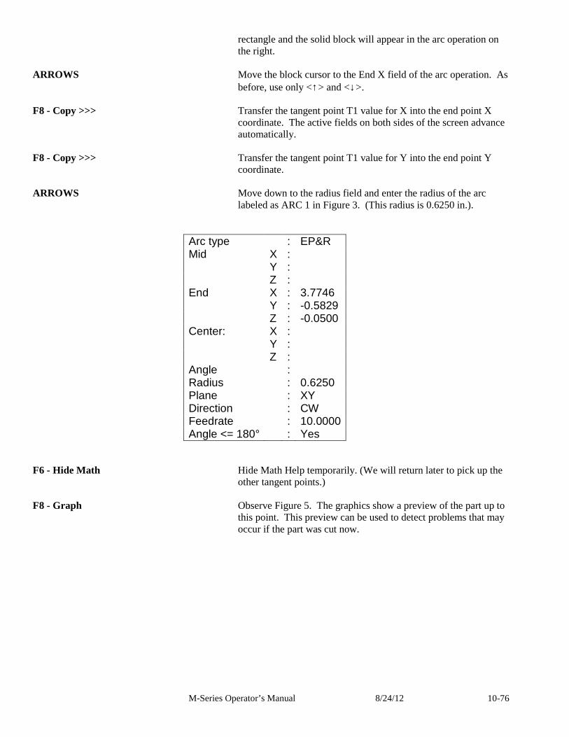
M-Series Operator’s Manual 8/24/12 10-76
rectangle and the solid block will appear in the arc operation on the right.
ARROWS Move the block cursor to the End X field of the arc operation. As
before, use only <↑> and <↓>. F8 - Copy >>> Transfer the tangent point T1 value for X into the end point X
coordinate. The active fields on both sides of the screen advance automatically.
F8 - Copy >>> Transfer the tangent point T1 value for Y into the end point Y
coordinate. ARROWS Move down to the radius field and enter the radius of the arc
labeled as ARC 1 in Figure 3. (This radius is 0.6250 in.).
Arc type : EP&R Mid X : Y : Z : End X : 3.7746 Y : -0.5829 Z : -0.0500 Center: X : Y : Z : Angle : Radius : 0.6250 Plane : XY Direction : CW Feedrate : 10.0000 Angle <= 180° : Yes
F6 - Hide Math Hide Math Help temporarily. (We will return later to pick up the other tangent points.)
F8 - Graph Observe Figure 5. The graphics show a preview of the part up to
this point. This preview can be used to detect problems that may occur if the part was cut now.
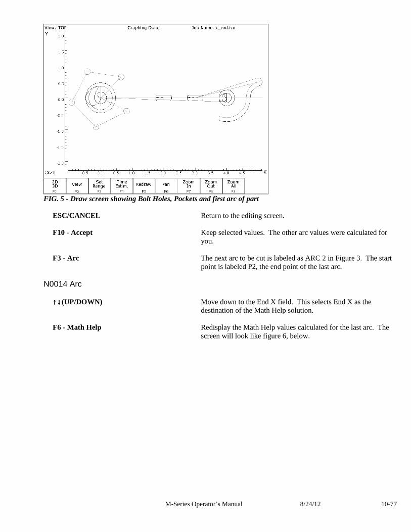
M-Series Operator’s Manual 8/24/12 10-77
FIG. 5 - Draw screen showing Bolt Holes, Pockets and first arc of part
ESC/CANCEL Return to the editing screen. F10 - Accept Keep selected values. The other arc values were calculated for
you. F3 - Arc The next arc to be cut is labeled as ARC 2 in Figure 3. The start
point is labeled P2, the end point of the last arc.
N0014 Arc ↑↑↑↑↓↓↓↓(UP/DOWN) Move down to the End X field. This selects End X as the
destination of the Math Help solution. F6 - Math Help Redisplay the Math Help values calculated for the last arc. The
screen will look like figure 6, below.
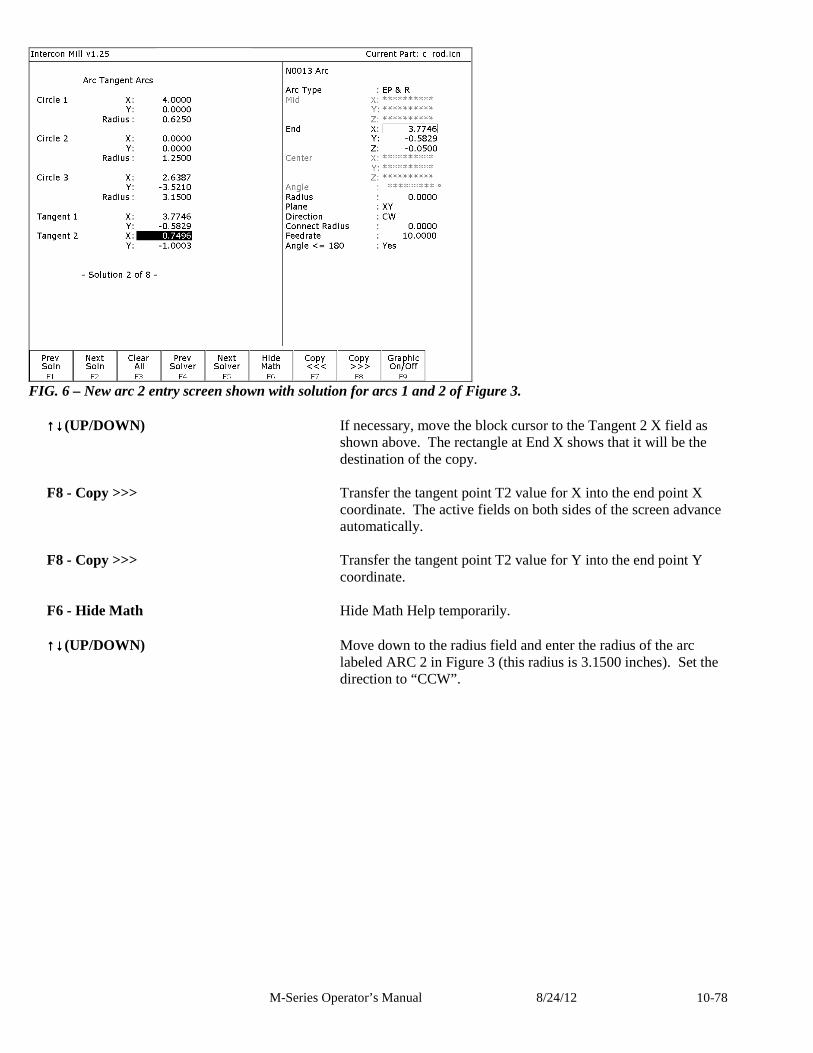
M-Series Operator’s Manual 8/24/12 10-78
FIG. 6 – New arc 2 entry screen shown with solution for arcs 1 and 2 of Figure 3.
↑↑↑↑↓↓↓↓(UP/DOWN) If necessary, move the block cursor to the Tangent 2 X field as shown above. The rectangle at End X shows that it will be the destination of the copy.
F8 - Copy >>> Transfer the tangent point T2 value for X into the end point X
coordinate. The active fields on both sides of the screen advance automatically.
F8 - Copy >>> Transfer the tangent point T2 value for Y into the end point Y
coordinate. F6 - Hide Math Hide Math Help temporarily. ↑↑↑↑↓↓↓↓(UP/DOWN) Move down to the radius field and enter the radius of the arc
labeled ARC 2 in Figure 3 (this radius is 3.1500 inches). Set the direction to “CCW”.
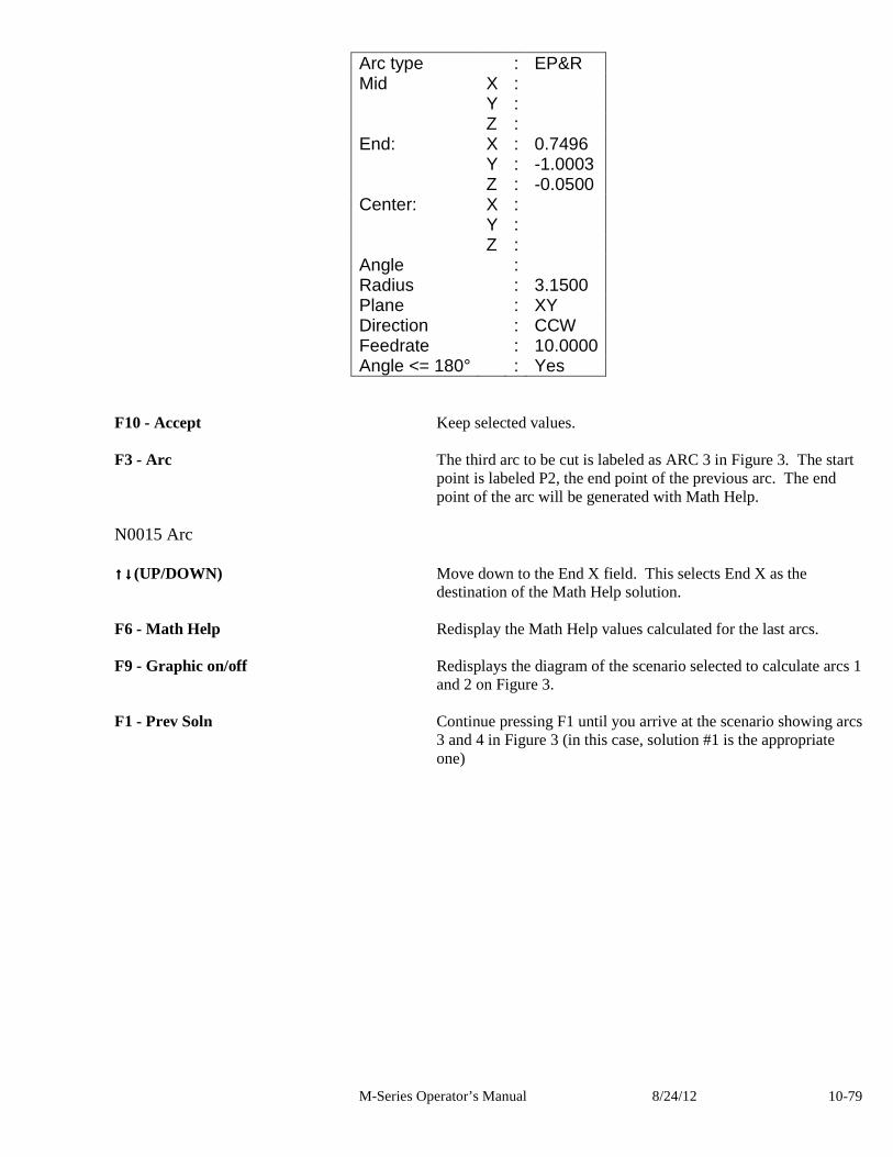
M-Series Operator’s Manual 8/24/12 10-79
Arc type : EP&R Mid X : Y : Z : End: X : 0.7496 Y : -1.0003 Z : -0.0500 Center: X : Y : Z : Angle : Radius : 3.1500 Plane : XY Direction : CCW Feedrate : 10.0000 Angle <= 180° : Yes
F10 - Accept Keep selected values. F3 - Arc The third arc to be cut is labeled as ARC 3 in Figure 3. The start
point is labeled P2, the end point of the previous arc. The end point of the arc will be generated with Math Help.
N0015 Arc ↑↑↑↑↓↓↓↓(UP/DOWN) Move down to the End X field. This selects End X as the
destination of the Math Help solution. F6 - Math Help Redisplay the Math Help values calculated for the last arcs.
F9 - Graphic on/off Redisplays the diagram of the scenario selected to calculate arcs 1
and 2 on Figure 3. F1 - Prev Soln Continue pressing F1 until you arrive at the scenario showing arcs
3 and 4 in Figure 3 (in this case, solution #1 is the appropriate one)
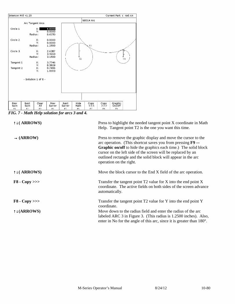
M-Series Operator’s Manual 8/24/12 10-80
FIG. 7 - Math Help solution for arcs 3 and 4.
↑↑↑↑↓↓↓↓( ARROWS) Press to highlight the needed tangent point X coordinate in Math Help. Tangent point T2 is the one you want this time.
→→→→ (ARROW) Press to remove the graphic display and move the cursor to the
arc operation. (This shortcut saves you from pressing F9 –-Graphic on/off to hide the graphics each time.) The solid block cursor on the left side of the screen will be replaced by an outlined rectangle and the solid block will appear in the arc operation on the right.
↑↑↑↑↓↓↓↓( ARROWS) Move the block cursor to the End X field of the arc operation. F8 - Copy >>> Transfer the tangent point T2 value for X into the end point X
coordinate. The active fields on both sides of the screen advance automatically.
F8 - Copy >>> Transfer the tangent point T2 value for Y into the end point Y
coordinate. ↑↑↑↑↓↓↓↓(ARROWS) Move down to the radius field and enter the radius of the arc
labeled ARC 3 in Figure 3. (This radius is 1.2500 inches). Also, enter in No for the angle of this arc, since it is greater than 180°.
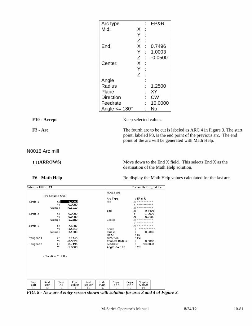
M-Series Operator’s Manual 8/24/12 10-81
Arc type : EP&R Mid: X : Y : Z : End: X : 0.7496 Y : 1.0003 Z : -0.0500 Center: X : Y : Z : Angle : Radius : 1.2500 Plane : XY Direction : CW Feedrate : 10.0000 Angle <= 180° : No
F10 - Accept Keep selected values. F3 - Arc The fourth arc to be cut is labeled as ARC 4 in Figure 3. The start
point, labeled P3, is the end point of the previous arc. The end point of the arc will be generated with Math Help.
N0016 Arc mill
↑↑↑↑↓↓↓↓(ARROWS) Move down to the End X field. This selects End X as the destination of the Math Help solution.
F6 - Math Help Re-display the Math Help values calculated for the last arc.
FIG. 8 - New arc 4 entry screen shown with solution for arcs 3 and 4 of Figure 3.
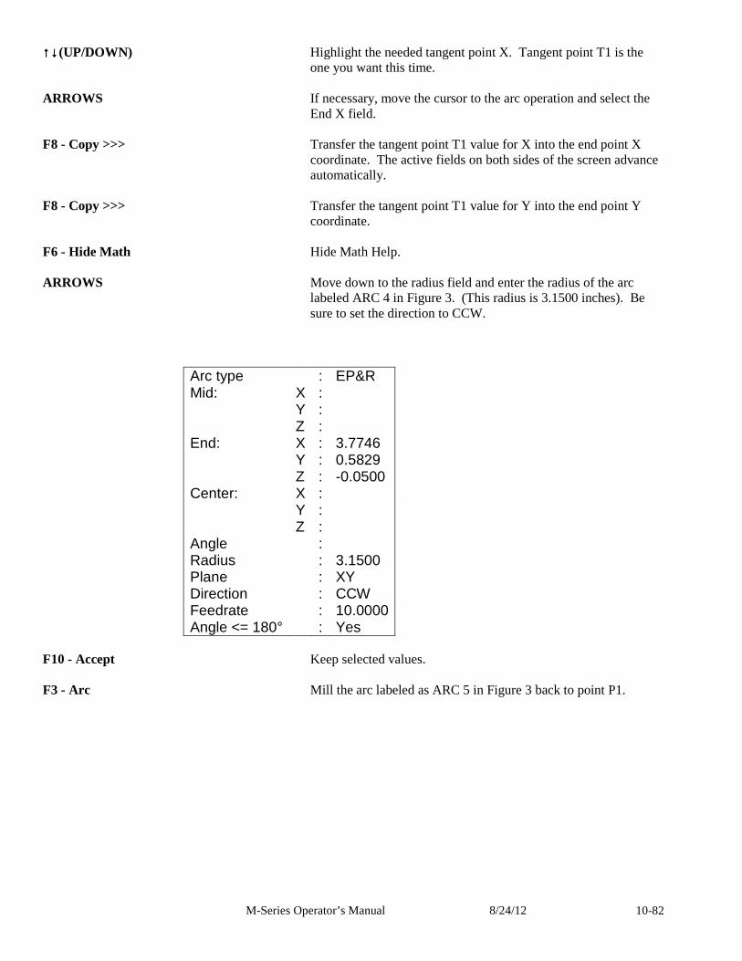
M-Series Operator’s Manual 8/24/12 10-82
↑↑↑↑↓↓↓↓(UP/DOWN) Highlight the needed tangent point X. Tangent point T1 is the one you want this time.
ARROWS If necessary, move the cursor to the arc operation and select the
End X field. F8 - Copy >>> Transfer the tangent point T1 value for X into the end point X
coordinate. The active fields on both sides of the screen advance automatically.
F8 - Copy >>> Transfer the tangent point T1 value for Y into the end point Y
coordinate. F6 - Hide Math Hide Math Help. ARROWS Move down to the radius field and enter the radius of the arc
labeled ARC 4 in Figure 3. (This radius is 3.1500 inches). Be sure to set the direction to CCW.
Arc type : EP&R Mid: X : Y : Z : End: X : 3.7746 Y : 0.5829 Z : -0.0500 Center: X : Y : Z : Angle : Radius : 3.1500 Plane : XY Direction : CCW Feedrate : 10.0000 Angle <= 180° : Yes
F10 - Accept Keep selected values. F3 - Arc Mill the arc labeled as ARC 5 in Figure 3 back to point P1.
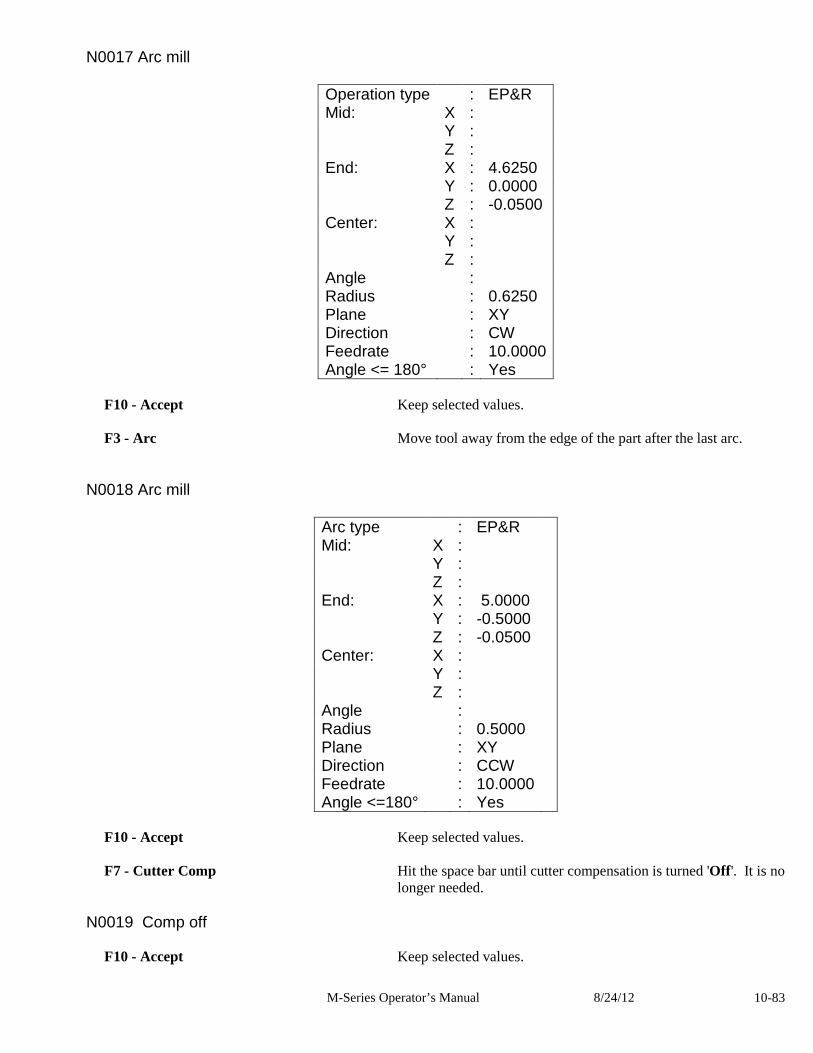
M-Series Operator’s Manual 8/24/12 10-83
N0017 Arc mill
Operation type : EP&R Mid: X : Y : Z : End: X : 4.6250 Y : 0.0000 Z : -0.0500 Center: X : Y : Z : Angle : Radius : 0.6250 Plane : XY Direction : CW Feedrate : 10.0000 Angle <= 180° : Yes
F10 - Accept Keep selected values. F3 - Arc Move tool away from the edge of the part after the last arc.
N0018 Arc mill
Arc type : EP&R Mid: X : Y : Z : End: X : 5.0000 Y : -0.5000 Z : -0.0500 Center: X : Y : Z : Angle : Radius : 0.5000 Plane : XY Direction : CCW Feedrate : 10.0000 Angle <=180° : Yes
F10 - Accept Keep selected values. F7 - Cutter Comp Hit the space bar until cutter compensation is turned 'Off '. It is no
longer needed. N0019 Comp off
F10 - Accept Keep selected values.
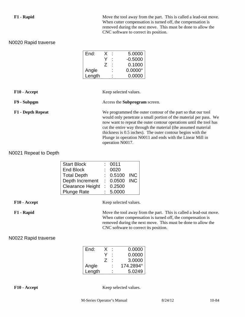
M-Series Operator’s Manual 8/24/12 10-84
F1 - Rapid Move the tool away from the part. This is called a lead-out move. When cutter compensation is turned off, the compensation is removed during the next move. This must be done to allow the CNC software to correct its position.
N0020 Rapid traverse
End: X : 5.0000 Y : -0.5000 Z : 0.1000 Angle : 0.0000° Length : 0.0000
F10 - Accept Keep selected values. F9 - Subpgm Access the Subprogram screen.
F1 - Depth Repeat We programmed the outer contour of the part so that our tool
would only penetrate a small portion of the material per pass. We now want to repeat the outer contour operations until the tool has cut the entire way through the material (the assumed material thickness is 0.5 inches). The outer contour begins with the Plunge in operation N0011 and ends with the Linear Mill in operation N0017.
N0021 Repeat to Depth
Start Block : 0011 End Block : 0020 Total Depth : 0.5100 INC Depth Increment : 0.0500 INC Clearance Height : 0.2500 Plunge Rate : 5.0000
F10 - Accept Keep selected values. F1 - Rapid Move the tool away from the part. This is called a lead-out move.
When cutter compensation is turned off, the compensation is removed during the next move. This must be done to allow the CNC software to correct its position.
N0022 Rapid traverse
End: X : 0.0000 Y : 0.0000 Z : 3.0000 Angle : 174.2894° Length : 5.0249
F10 - Accept Keep selected values.
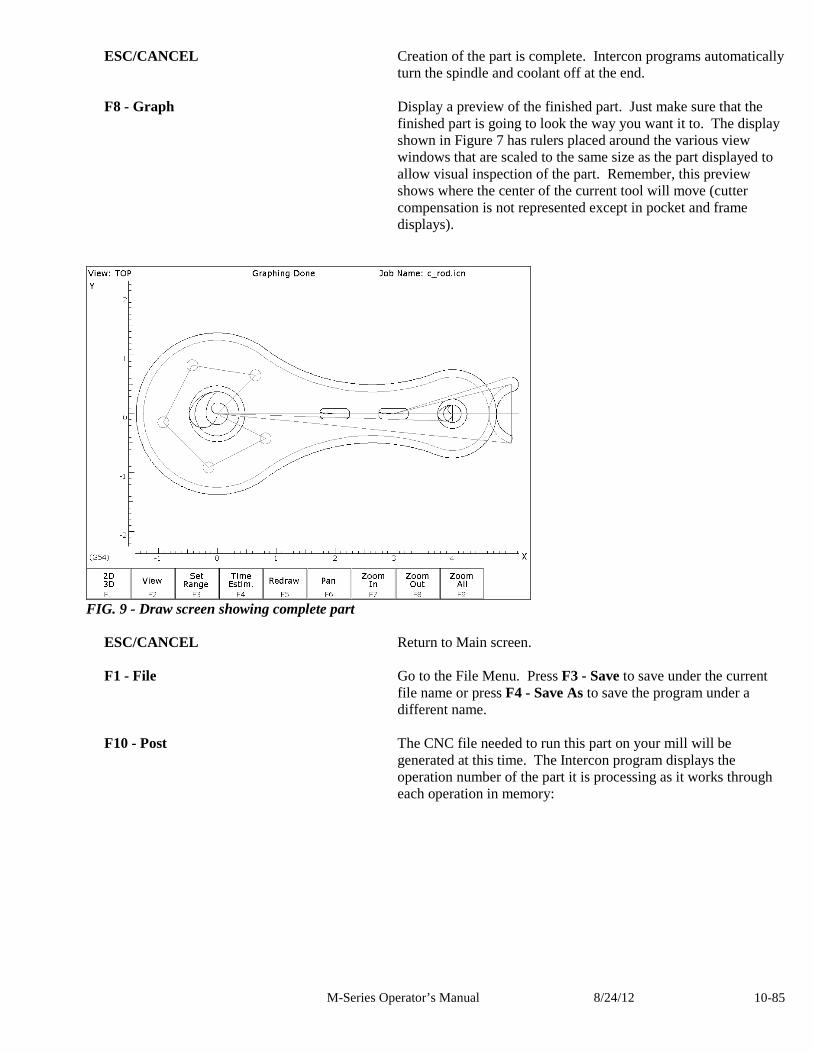
M-Series Operator’s Manual 8/24/12 10-85
ESC/CANCEL Creation of the part is complete. Intercon programs automatically turn the spindle and coolant off at the end.
F8 - Graph Display a preview of the finished part. Just make sure that the
finished part is going to look the way you want it to. The display shown in Figure 7 has rulers placed around the various view windows that are scaled to the same size as the part displayed to allow visual inspection of the part. Remember, this preview shows where the center of the current tool will move (cutter compensation is not represented except in pocket and frame displays).
FIG. 9 - Draw screen showing complete part
ESC/CANCEL Return to Main screen. F1 - File Go to the File Menu. Press F3 - Save to save under the current
file name or press F4 - Save As to save the program under a different name.
F10 - Post The CNC file needed to run this part on your mill will be
generated at this time. The Intercon program displays the operation number of the part it is processing as it works through each operation in memory:
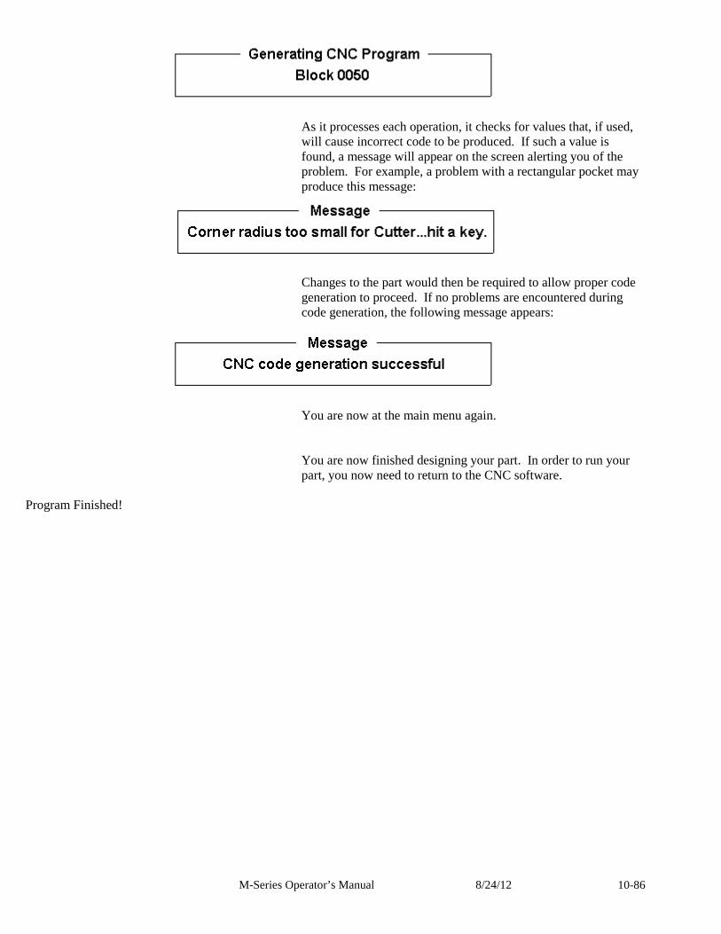
M-Series Operator’s Manual 8/24/12 10-86
As it processes each operation, it checks for values that, if used,
will cause incorrect code to be produced. If such a value is found, a message will appear on the screen alerting you of the problem. For example, a problem with a rectangular pocket may produce this message:
Changes to the part would then be required to allow proper code
generation to proceed. If no problems are encountered during code generation, the following message appears:
You are now at the main menu again.
You are now finished designing your part. In order to run your part, you now need to return to the CNC software.
Program Finished!
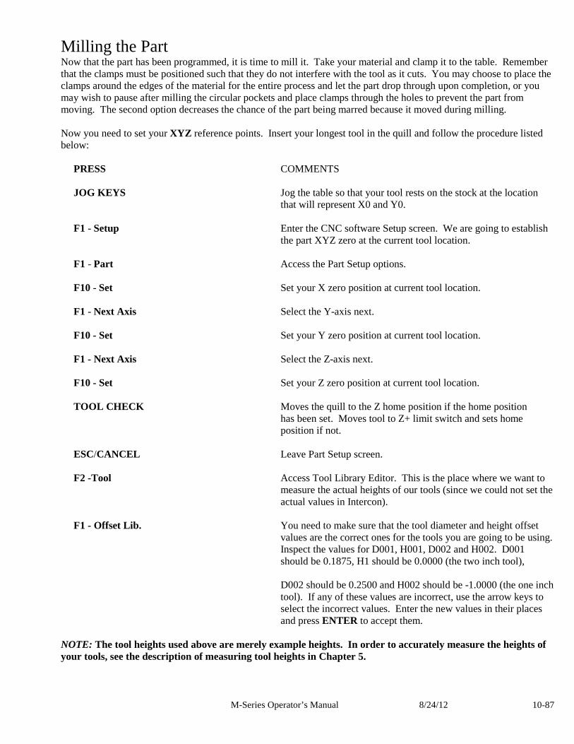
M-Series Operator’s Manual 8/24/12 10-87
Milling the Part Now that the part has been programmed, it is time to mill it. Take your material and clamp it to the table. Remember that the clamps must be positioned such that they do not interfere with the tool as it cuts. You may choose to place the clamps around the edges of the material for the entire process and let the part drop through upon completion, or you may wish to pause after milling the circular pockets and place clamps through the holes to prevent the part from moving. The second option decreases the chance of the part being marred because it moved during milling. Now you need to set your XYZ reference points. Insert your longest tool in the quill and follow the procedure listed below:
PRESS COMMENTS JOG KEYS Jog the table so that your tool rests on the stock at the location
that will represent X0 and Y0. F1 - Setup Enter the CNC software Setup screen. We are going to establish
the part XYZ zero at the current tool location. F1 - Part Access the Part Setup options. F10 - Set Set your X zero position at current tool location. F1 - Next Axis Select the Y-axis next. F10 - Set Set your Y zero position at current tool location. F1 - Next Axis Select the Z-axis next. F10 - Set Set your Z zero position at current tool location. TOOL CHECK Moves the quill to the Z home position if the home position has been set. Moves tool to Z+ limit switch and sets home
position if not. ESC/CANCEL Leave Part Setup screen. F2 -Tool Access Tool Library Editor. This is the place where we want to
measure the actual heights of our tools (since we could not set the actual values in Intercon).
F1 - Offset Lib. You need to make sure that the tool diameter and height offset
values are the correct ones for the tools you are going to be using. Inspect the values for D001, H001, D002 and H002. D001 should be 0.1875, H1 should be 0.0000 (the two inch tool),
D002 should be 0.2500 and H002 should be -1.0000 (the one inch
tool). If any of these values are incorrect, use the arrow keys to select the incorrect values. Enter the new values in their places and press ENTER to accept them.
NOTE: The tool heights used above are merely example heights. In order to accurately measure the heights of your tools, see the description of measuring tool heights in Chapter 5.
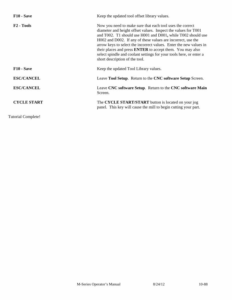
M-Series Operator’s Manual 8/24/12 10-88
F10 - Save Keep the updated tool offset library values. F2 - Tools Now you need to make sure that each tool uses the correct
diameter and height offset values. Inspect the values for T001 and T002. T1 should use H001 and D001, while T002 should use H002 and D002. If any of these values are incorrect, use the arrow keys to select the incorrect values. Enter the new values in their places and press ENTER to accept them. You may also select spindle and coolant settings for your tools here, or enter a short description of the tool.
F10 - Save Keep the updated Tool Library values. ESC/CANCEL Leave Tool Setup. Return to the CNC software Setup Screen. ESC/CANCEL Leave CNC software Setup. Return to the CNC software Main
Screen. CYCLE START The CYCLE START/START button is located on your jog
panel. This key will cause the mill to begin cutting your part.
Tutorial Complete!
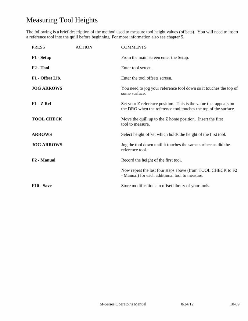
M-Series Operator’s Manual 8/24/12 10-89
Measuring Tool Heights The following is a brief description of the method used to measure tool height values (offsets). You will need to insert a reference tool into the quill before beginning. For more information also see chapter 5.
PRESS ACTION COMMENTS F1 - Setup From the main screen enter the Setup. F2 - Tool Enter tool screen. F1 - Offset Lib. Enter the tool offsets screen. JOG ARROWS You need to jog your reference tool down so it touches the top of
some surface. F1 - Z Ref Set your Z reference position. This is the value that appears on
the DRO when the reference tool touches the top of the surface. TOOL CHECK Move the quill up to the Z home position. Insert the first tool to measure. ARROWS Select height offset which holds the height of the first tool. JOG ARROWS Jog the tool down until it touches the same surface as did the
reference tool. F2 - Manual Record the height of the first tool. Now repeat the last four steps above (from TOOL CHECK to F2
- Manual) for each additional tool to measure. F10 - Save Store modifications to offset library of your tools.

M-Series Operator’s Manual 8/24/12 10-90
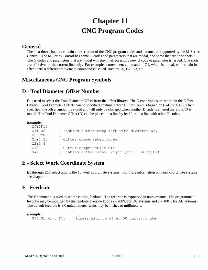
M-Series Operator’s Manual 8/24/12 11-1
Chapter 11 CNC Program Codes
General
The next three chapters contain a description of the CNC program codes and parameters supported by the M-Series Control. The M-Series Control has some G codes and parameters that are modal, and some that are "one shots." The G codes and parameters that are modal will stay in effect until a new G code or parameter is issued. One shots are effective for the current line only. For example, a movement command of G1, which is modal, will remain in effect until a different movement command is issued, such as G0, G2, G3, etc.
Miscellaneous CNC Program Symbols
D - Tool Diameter Offset Number D is used to select the Tool Diameter Offset from the offset library. The D code values are stored in the Offset Library. Tool Diameter Offsets can be specified anytime before Cutter Comp is turned on (G41 or G42). Once specified, the offset amount is stored and will only be changed when another D code is entered therefore, D is modal. The Tool Diameter Offset (D) can be placed on a line by itself or on a line with other G-codes. Example:
X0Y0F10 ; G41 D2 ; Enables cutter comp left with diameter D2 . G1X0Y0 ; X1Y1.25 ; Cutter compensated moves X2Y1.4 ; G40 ; Cutter compensation off G42 ; Enables cutter comp. right (still using D2)
E - Select Work Coordinate System E1 through E18 select among the 18 work coordinate systems. For more information on work coordinate systems see chapter 4.
F - Feedrate The F command is used to set the cutting feedrate. The feedrate is expressed in units/minute. The programmed feedrate may be modified by the feedrate override knob (2 - 200% for DC systems and 2 – 100% for AC systems). The default feedrate is 3.0 units/minute. Units may be inches or millimeters. Example:
G90 G1 X1.0 F50 ; linear mill to X1 at 50 units/min ute
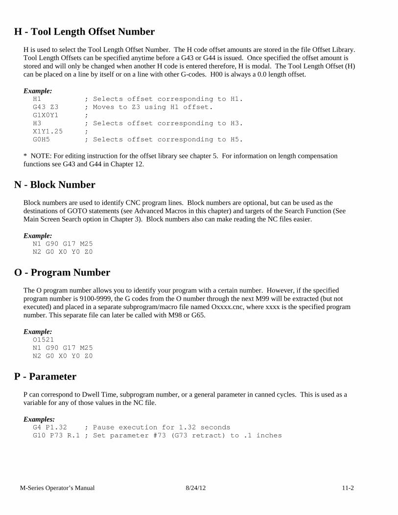
M-Series Operator’s Manual 8/24/12 11-2
H - Tool Length Offset Number H is used to select the Tool Length Offset Number. The H code offset amounts are stored in the file Offset Library. Tool Length Offsets can be specified anytime before a G43 or G44 is issued. Once specified the offset amount is stored and will only be changed when another H code is entered therefore, H is modal. The Tool Length Offset (H) can be placed on a line by itself or on a line with other G-codes. H00 is always a 0.0 length offset. Example:
H1 ; Selects offset corresponding to H1. G43 Z3 ; Moves to Z3 using H1 offset. G1X0Y1 ; H3 ; Selects offset corresponding to H3. X1Y1.25 ; G0H5 ; Selects offset corresponding to H5.
* NOTE: For editing instruction for the offset library see chapter 5. For information on length compensation functions see G43 and G44 in Chapter 12.
N - Block Number Block numbers are used to identify CNC program lines. Block numbers are optional, but can be used as the destinations of GOTO statements (see Advanced Macros in this chapter) and targets of the Search Function (See Main Screen Search option in Chapter 3). Block numbers also can make reading the NC files easier. Example:
N1 G90 G17 M25 N2 G0 X0 Y0 Z0
O - Program Number The O program number allows you to identify your program with a certain number. However, if the specified program number is 9100-9999, the G codes from the O number through the next M99 will be extracted (but not executed) and placed in a separate subprogram/macro file named Oxxxx.cnc, where xxxx is the specified program number. This separate file can later be called with M98 or G65. Example:
O1521 N1 G90 G17 M25 N2 G0 X0 Y0 Z0
P - Parameter P can correspond to Dwell Time, subprogram number, or a general parameter in canned cycles. This is used as a variable for any of those values in the NC file. Examples:
G4 P1.32 ; Pause execution for 1.32 seconds G10 P73 R.1 ; Set parameter #73 (G73 retract) to .1 inches
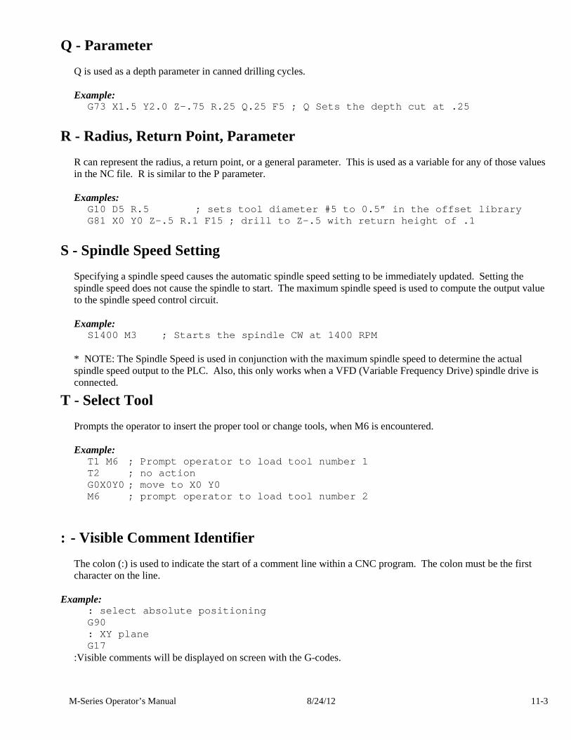
M-Series Operator’s Manual 8/24/12 11-3
Q - Parameter Q is used as a depth parameter in canned drilling cycles. Example:
G73 X1.5 Y2.0 Z-.75 R.25 Q.25 F5 ; Q Sets the depth cut at .25
R - Radius, Return Point, Parameter R can represent the radius, a return point, or a general parameter. This is used as a variable for any of those values in the NC file. R is similar to the P parameter. Examples:
G10 D5 R.5 ; sets tool diameter #5 to 0.5” in the offset library G81 X0 Y0 Z-.5 R.1 F15 ; drill to Z-.5 with return height of .1
S - Spindle Speed Setting Specifying a spindle speed causes the automatic spindle speed setting to be immediately updated. Setting the spindle speed does not cause the spindle to start. The maximum spindle speed is used to compute the output value to the spindle speed control circuit. Example:
S1400 M3 ; Starts the spindle CW at 1400 RPM * NOTE: The Spindle Speed is used in conjunction with the maximum spindle speed to determine the actual spindle speed output to the PLC. Also, this only works when a VFD (Variable Frequency Drive) spindle drive is connected.
T - Select Tool Prompts the operator to insert the proper tool or change tools, when M6 is encountered. Example:
T1 M6 ; Prompt operator to load tool number 1 T2 ; no action G0X0Y0 ; move to X0 Y0 M6 ; prompt operator to load tool number 2
: - Visible Comment Identifier The colon (:) is used to indicate the start of a comment line within a CNC program. The colon must be the first character on the line.
Example: : select absolute positioning G90 : XY plane G17
:Visible comments will be displayed on screen with the G-codes.
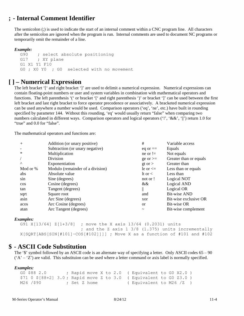
M-Series Operator’s Manual 8/24/12 11-4
; - Internal Comment Identifier The semicolon (;) is used to indicate the start of an internal comment within a CNC program line. All characters after the semicolon are ignored when the program is run. Internal comments are used to document NC programs or temporarily omit the remainder of a line. Example:
G90 ; select absolute positioning G17 ; XY plane G1 X1 Y1 F10 G0 ; X0 Y0 ; G0 selected with no movement
[ ] – Numerical Expression The left bracket ‘[‘ and right bracket ‘]’ are used to delimit a numerical expression. Numerical expressions can contain floating-point numbers or user and system variables in combination with mathematical operators and functions. The left parenthesis ‘(‘ or bracket ‘[‘ and right parenthesis ‘)’ or bracket ‘]’ can be used between the first left bracket and last right bracket to force operator precedence or associatively. A bracketed numerical expression can be used anywhere a number would be used. Comparison operators (‘eq’, ‘ne’, etc.) have built in rounding specified by parameter 144. Without this rounding, ‘eq’ would usually return “false” when comparing two numbers calculated in different ways. Comparison operators and logical operators (‘!’, ‘&&’, ‘||’) return 1.0 for “true” and 0.0 for “false”. The mathematical operators and functions are:
+ Addition (or unary positive) # Variable access - Subtraction (or unary negative) eq or == Equals * Multiplication ne or != Not equals / Division ge or >= Greater than or equals ^ Exponentiation gt or > Greater than Mod or % Modulo (remainder of a division) le or <= Less than or equals abs Absolute value lt or < Less than sin Sine (degrees) not or ! Logical NOT cos Cosine (degrees) && Logical AND tan Tangent (degrees) || Logical OR sqrt Square root and Bit-wise AND asin Arc Sine (degrees) xor Bit-wise exclusive OR acos Arc Cosine (degrees) or Bit-wise OR atan Arc Tangent (degrees) ~ Bit-wise complement
Examples:
G91 X[13/64] Z[1+3/8] ; move the X axis 13/64 (0.2 031) units ; and the Z axis 1 3/8 (1.37 5) units incrementally X[SQRT[ABS[SIN[#101]-COS[#102]]]] ; Move X as a fun ction of #101 and #102
$ - ASCII Code Substitution The ‘$’ symbol followed by an ASCII code is an alternate way of specifying a letter. Only ASCII codes 65 – 90 (‘A’ – ‘Z’) are valid. This substituion can be used where a letter command or axis label is normally specified. Examples:
G0 $88 2.0 ; Rapid move X to 2.0 ( Equivalent to G0 X2.0 ) $71 0 $[88+2] 3.0 ; Rapid move Z to 3.0 ( Equivale nt to G0 Z3.0 ) M26 /$90 ; Set Z home ( Equivalent to M2 6 /Z )
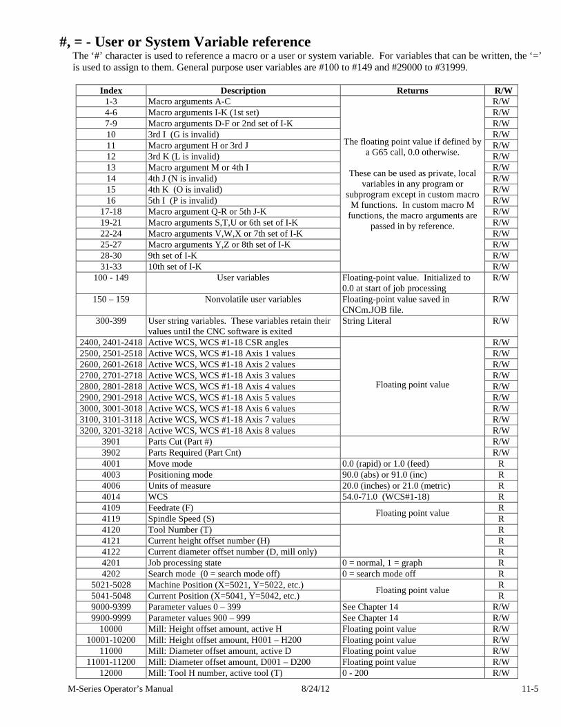
M-Series Operator’s Manual 8/24/12 11-5
#, = - User or System Variable reference The ‘#’ character is used to reference a macro or a user or system variable. For variables that can be written, the ‘=’ is used to assign to them. General purpose user variables are #100 to #149 and #29000 to #31999.
Index Description Returns R/W 1-3 Macro arguments A-C R/W 4-6 Macro arguments I-K (1st set) R/W 7-9 Macro arguments D-F or 2nd set of I-K R/W 10 3rd I (G is invalid) R/W 11 Macro argument H or 3rd J R/W 12 3rd K (L is invalid) R/W 13 Macro argument M or 4th I R/W 14 4th J (N is invalid) R/W 15 4th K (O is invalid) R/W 16 5th I (P is invalid) R/W
17-18 Macro argument Q-R or 5th J-K R/W 19-21 Macro arguments S,T,U or 6th set of I-K R/W 22-24 Macro arguments V,W,X or 7th set of I-K R/W 25-27 Macro arguments Y,Z or 8th set of I-K R/W 28-30 9th set of I-K R/W 31-33 10th set of I-K
The floating point value if defined by a G65 call, 0.0 otherwise.
These can be used as private, local
variables in any program or subprogram except in custom macro M functions. In custom macro M
functions, the macro arguments are passed in by reference.
R/W 100 - 149 User variables Floating-point value. Initialized to
0.0 at start of job processing R/W
150 – 159 Nonvolatile user variables Floating-point value saved in CNCm.JOB file.
R/W
300-399 User string variables. These variables retain their values until the CNC software is exited
String Literal R/W
2400, 2401-2418 Active WCS, WCS #1-18 CSR angles R/W 2500, 2501-2518 Active WCS, WCS #1-18 Axis 1 values R/W 2600, 2601-2618 Active WCS, WCS #1-18 Axis 2 values R/W 2700, 2701-2718 Active WCS, WCS #1-18 Axis 3 values R/W 2800, 2801-2818 Active WCS, WCS #1-18 Axis 4 values R/W 2900, 2901-2918 Active WCS, WCS #1-18 Axis 5 values R/W 3000, 3001-3018 Active WCS, WCS #1-18 Axis 6 values R/W 3100, 3101-3118 Active WCS, WCS #1-18 Axis 7 values R/W 3200, 3201-3218 Active WCS, WCS #1-18 Axis 8 values
Floating point value
R/W 3901 Parts Cut (Part #) R/W 3902 Parts Required (Part Cnt)
R/W
4001 Move mode 0.0 (rapid) or 1.0 (feed) R 4003 Positioning mode 90.0 (abs) or 91.0 (inc) R 4006 Units of measure 20.0 (inches) or 21.0 (metric) R 4014 WCS 54.0-71.0 (WCS#1-18) R 4109 Feedrate (F) R 4119 Spindle Speed (S)
Floating point value R
4120 Tool Number (T) R 4121 Current height offset number (H) R 4122 Current diameter offset number (D, mill only)
R 4201 Job processing state 0 = normal, 1 = graph R 4202 Search mode (0 = search mode off) 0 = search mode off R
5021-5028 Machine Position (X=5021, Y=5022, etc.) R 5041-5048 Current Position (X=5041, Y=5042, etc.)
Floating point value R
9000-9399 Parameter values 0 – 399 See Chapter 14 R/W 9900-9999 Parameter values 900 – 999 See Chapter 14 R/W
10000 Mill: Height offset amount, active H Floating point value R/W 10001-10200 Mill: Height offset amount, H001 – H200 Floating point value R/W
11000 Mill: Diameter offset amount, active D Floating point value R/W 11001-11200 Mill: Diameter offset amount, D001 – D200 Floating point value R/W
12000 Mill: Tool H number, active tool (T) 0 - 200 R/W
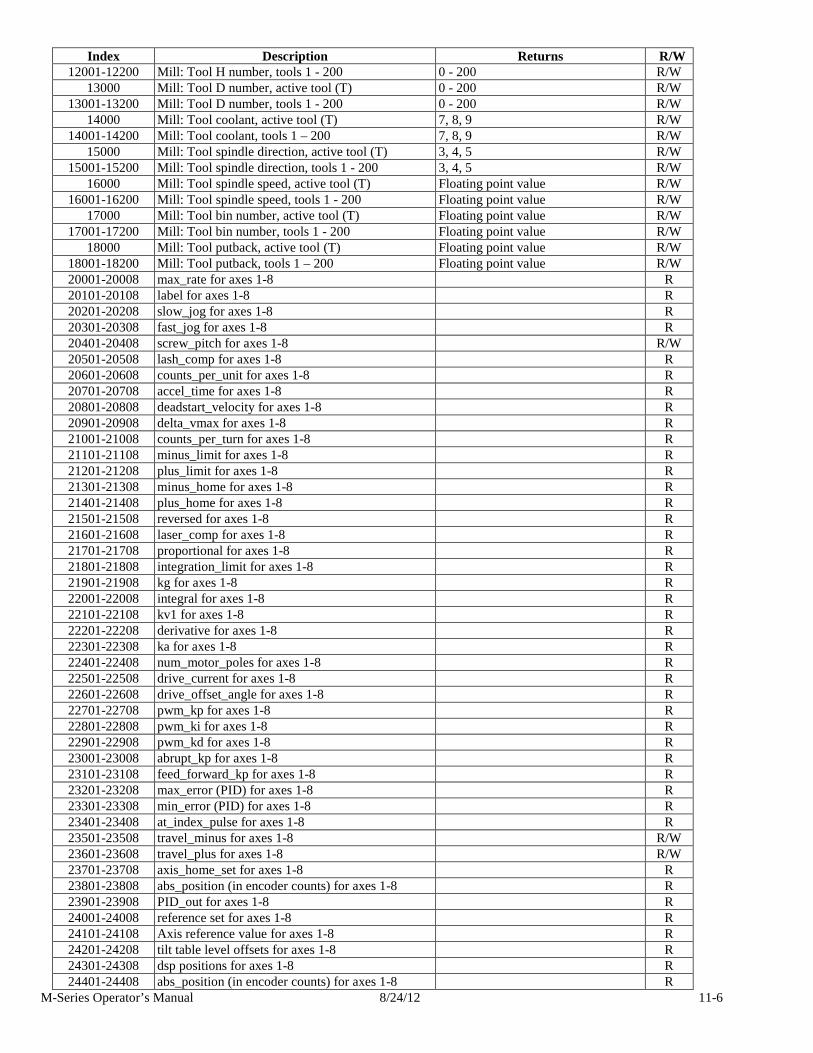
M-Series Operator’s Manual 8/24/12 11-6
Index Description Returns R/W 12001-12200 Mill: Tool H number, tools 1 - 200 0 - 200 R/W
13000 Mill: Tool D number, active tool (T) 0 - 200 R/W 13001-13200 Mill: Tool D number, tools 1 - 200 0 - 200 R/W
14000 Mill: Tool coolant, active tool (T) 7, 8, 9 R/W 14001-14200 Mill: Tool coolant, tools 1 – 200 7, 8, 9 R/W
15000 Mill: Tool spindle direction, active tool (T) 3, 4, 5 R/W 15001-15200 Mill: Tool spindle direction, tools 1 - 200 3, 4, 5 R/W
16000 Mill: Tool spindle speed, active tool (T) Floating point value R/W 16001-16200 Mill: Tool spindle speed, tools 1 - 200 Floating point value R/W
17000 Mill: Tool bin number, active tool (T) Floating point value R/W 17001-17200 Mill: Tool bin number, tools 1 - 200 Floating point value R/W
18000 Mill: Tool putback, active tool (T) Floating point value R/W 18001-18200 Mill: Tool putback, tools 1 – 200 Floating point value R/W 20001-20008 max_rate for axes 1-8 R 20101-20108 label for axes 1-8 R 20201-20208 slow_jog for axes 1-8 R 20301-20308 fast_jog for axes 1-8 R 20401-20408 screw_pitch for axes 1-8 R/W 20501-20508 lash_comp for axes 1-8 R 20601-20608 counts_per_unit for axes 1-8 R 20701-20708 accel_time for axes 1-8 R 20801-20808 deadstart_velocity for axes 1-8 R 20901-20908 delta_vmax for axes 1-8 R 21001-21008 counts_per_turn for axes 1-8 R 21101-21108 minus_limit for axes 1-8 R 21201-21208 plus_limit for axes 1-8 R 21301-21308 minus_home for axes 1-8 R 21401-21408 plus_home for axes 1-8 R 21501-21508 reversed for axes 1-8 R 21601-21608 laser_comp for axes 1-8 R 21701-21708 proportional for axes 1-8 R 21801-21808 integration_limit for axes 1-8 R 21901-21908 kg for axes 1-8 R 22001-22008 integral for axes 1-8 R 22101-22108 kv1 for axes 1-8 R 22201-22208 derivative for axes 1-8 R 22301-22308 ka for axes 1-8 R 22401-22408 num_motor_poles for axes 1-8 R 22501-22508 drive_current for axes 1-8 R 22601-22608 drive_offset_angle for axes 1-8 R 22701-22708 pwm_kp for axes 1-8 R 22801-22808 pwm_ki for axes 1-8 R 22901-22908 pwm_kd for axes 1-8 R 23001-23008 abrupt_kp for axes 1-8 R 23101-23108 feed_forward_kp for axes 1-8 R 23201-23208 max_error (PID) for axes 1-8 R 23301-23308 min_error (PID) for axes 1-8 R 23401-23408 at_index_pulse for axes 1-8 R 23501-23508 travel_minus for axes 1-8 R/W 23601-23608 travel_plus for axes 1-8 R/W 23701-23708 axis_home_set for axes 1-8 R 23801-23808 abs_position (in encoder counts) for axes 1-8 R 23901-23908 PID_out for axes 1-8 R 24001-24008 reference set for axes 1-8 R 24101-24108 Axis reference value for axes 1-8 R 24201-24208 tilt table level offsets for axes 1-8 R 24301-24308 dsp positions for axes 1-8 R 24401-24408 abs_position (in encoder counts) for axes 1-8 R
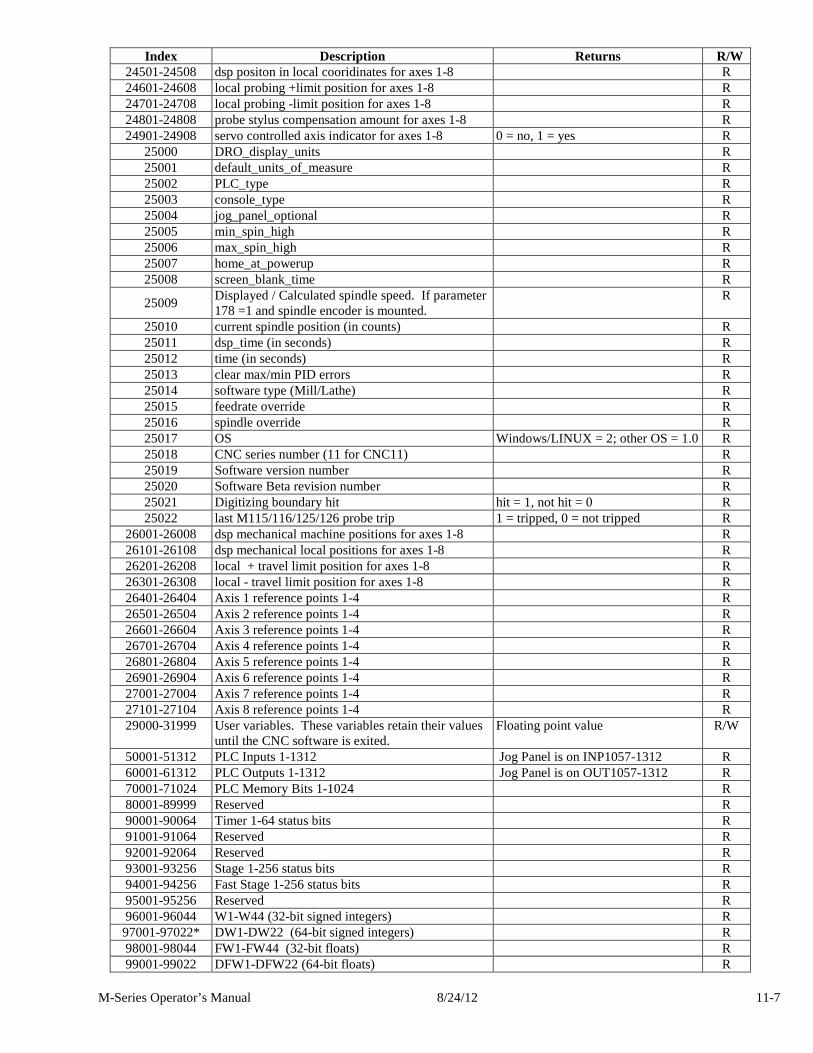
M-Series Operator’s Manual 8/24/12 11-7
Index Description Returns R/W 24501-24508 dsp positon in local cooridinates for axes 1-8 R 24601-24608 local probing +limit position for axes 1-8 R 24701-24708 local probing -limit position for axes 1-8 R 24801-24808 probe stylus compensation amount for axes 1-8 R 24901-24908 servo controlled axis indicator for axes 1-8 0 = no, 1 = yes R
25000 DRO_display_units R 25001 default_units_of_measure R 25002 PLC_type R 25003 console_type R 25004 jog_panel_optional R 25005 min_spin_high R 25006 max_spin_high R 25007 home_at_powerup R 25008 screen_blank_time R
25009 Displayed / Calculated spindle speed. If parameter 178 =1 and spindle encoder is mounted.
R
25010 current spindle position (in counts) R 25011 dsp_time (in seconds) R 25012 time (in seconds) R 25013 clear max/min PID errors R 25014 software type (Mill/Lathe) R 25015 feedrate override R 25016 spindle override R 25017 OS Windows/LINUX = 2; other OS = 1.0 R 25018 CNC series number (11 for CNC11) R 25019 Software version number R 25020 Software Beta revision number R 25021 Digitizing boundary hit hit = 1, not hit = 0 R 25022 last M115/116/125/126 probe trip 1 = tripped, 0 = not tripped R
26001-26008 dsp mechanical machine positions for axes 1-8 R 26101-26108 dsp mechanical local positions for axes 1-8 R 26201-26208 local + travel limit position for axes 1-8 R 26301-26308 local - travel limit position for axes 1-8 R 26401-26404 Axis 1 reference points 1-4 R 26501-26504 Axis 2 reference points 1-4 R 26601-26604 Axis 3 reference points 1-4 R 26701-26704 Axis 4 reference points 1-4 R 26801-26804 Axis 5 reference points 1-4 R 26901-26904 Axis 6 reference points 1-4 R 27001-27004 Axis 7 reference points 1-4 R 27101-27104 Axis 8 reference points 1-4 R 29000-31999 User variables. These variables retain their values
until the CNC software is exited. Floating point value R/W
50001-51312 PLC Inputs 1-1312 Jog Panel is on INP1057-1312 R 60001-61312 PLC Outputs 1-1312 Jog Panel is on OUT1057-1312 R 70001-71024 PLC Memory Bits 1-1024 R 80001-89999 Reserved R 90001-90064 Timer 1-64 status bits R 91001-91064 Reserved R 92001-92064 Reserved R 93001-93256 Stage 1-256 status bits R 94001-94256 Fast Stage 1-256 status bits R 95001-95256 Reserved R 96001-96044 W1-W44 (32-bit signed integers) R 97001-97022* DW1-DW22 (64-bit signed integers) R 98001-98044 FW1-FW44 (32-bit floats) R 99001-99022 DFW1-DFW22 (64-bit floats) R
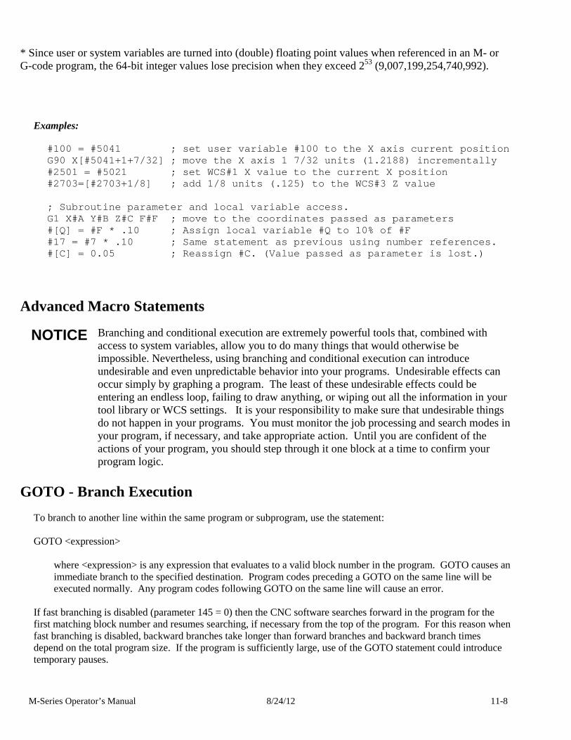
M-Series Operator’s Manual 8/24/12 11-8
* Since user or system variables are turned into (double) floating point values when referenced in an M- or G-code program, the 64-bit integer values lose precision when they exceed 253 (9,007,199,254,740,992).
Examples:
#100 = #5041 ; set user variable #100 to the X axis current position G90 X[#5041+1+7/32] ; move the X axis 1 7/32 units (1.2188) incrementally #2501 = #5021 ; set WCS#1 X value to the curr ent X position #2703=[#2703+1/8] ; add 1/8 units (.125) to the W CS#3 Z value ; Subroutine parameter and local variable access. G1 X#A Y#B Z#C F#F ; move to the coordinates passe d as parameters #[Q] = #F * .10 ; Assign local variable #Q to 1 0% of #F #17 = #7 * .10 ; Same statement as previous us ing number references. #[C] = 0.05 ; Reassign #C. (Value passed as parameter is lost.)
Advanced Macro Statements
NOTICE Branching and conditional execution are extremely powerful tools that, combined with access to system variables, allow you to do many things that would otherwise be impossible. Nevertheless, using branching and conditional execution can introduce undesirable and even unpredictable behavior into your programs. Undesirable effects can occur simply by graphing a program. The least of these undesirable effects could be entering an endless loop, failing to draw anything, or wiping out all the information in your tool library or WCS settings. It is your responsibility to make sure that undesirable things do not happen in your programs. You must monitor the job processing and search modes in your program, if necessary, and take appropriate action. Until you are confident of the actions of your program, you should step through it one block at a time to confirm your program logic.
GOTO - Branch Execution To branch to another line within the same program or subprogram, use the statement: GOTO <expression>
where <expression> is any expression that evaluates to a valid block number in the program. GOTO causes an immediate branch to the specified destination. Program codes preceding a GOTO on the same line will be executed normally. Any program codes following GOTO on the same line will cause an error.
If fast branching is disabled (parameter 145 = 0) then the CNC software searches forward in the program for the first matching block number and resumes searching, if necessary from the top of the program. For this reason when fast branching is disabled, backward branches take longer than forward branches and backward branch times depend on the total program size. If the program is sufficiently large, use of the GOTO statement could introduce temporary pauses.
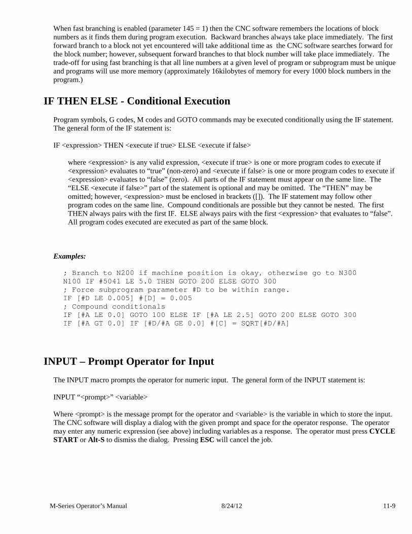
M-Series Operator’s Manual 8/24/12 11-9
When fast branching is enabled (parameter 145 = 1) then the CNC software remembers the locations of block numbers as it finds them during program execution. Backward branches always take place immediately. The first forward branch to a block not yet encountered will take additional time as the CNC software searches forward for the block number; however, subsequent forward branches to that block number will take place immediately. The trade-off for using fast branching is that all line numbers at a given level of program or subprogram must be unique and programs will use more memory (approximately 16kilobytes of memory for every 1000 block numbers in the program.)
IF THEN ELSE - Conditional Execution Program symbols, G codes, M codes and GOTO commands may be executed conditionally using the IF statement. The general form of the IF statement is: IF <expression> THEN <execute if true> ELSE <execute if false>
where <expression> is any valid expression, <execute if true> is one or more program codes to execute if <expression> evaluates to “true” (non-zero) and <execute if false> is one or more program codes to execute if <expression> evaluates to “false” (zero). All parts of the IF statement must appear on the same line. The “ELSE <execute if false>” part of the statement is optional and may be omitted. The “THEN” may be omitted; however, <expression> must be enclosed in brackets ([]). The IF statement may follow other program codes on the same line. Compound conditionals are possible but they cannot be nested. The first THEN always pairs with the first IF. ELSE always pairs with the first <expression> that evaluates to “false”. All program codes executed are executed as part of the same block.
Examples:
; Branch to N200 if machine position is okay, other wise go to N300 N100 IF #5041 LE 5.0 THEN GOTO 200 ELSE GOTO 300 ; Force subprogram parameter #D to be within range. IF [#D LE 0.005] #[D] = 0.005 ; Compound conditionals IF [#A LE 0.0] GOTO 100 ELSE IF [#A LE 2.5] GOTO 20 0 ELSE GOTO 300 IF [#A GT 0.0] IF [#D/#A GE 0.0] #[C] = SQRT[#D/#A]
INPUT – Prompt Operator for Input The INPUT macro prompts the operator for numeric input. The general form of the INPUT statement is: INPUT “<prompt>” <variable> Where <prompt> is the message prompt for the operator and <variable> is the variable in which to store the input. The CNC software will display a dialog with the given prompt and space for the operator response. The operator may enter any numeric expression (see above) including variables as a response. The operator must press CYCLE START or Alt-S to dismiss the dialog. Pressing ESC will cancel the job.
M-Series Operator’s Manual 8/24/12 11-10
The CNC software parses well ahead of the current execution to maximize throughput and efficiency. For this reason, an INPUT macro may prompt the operator for input immediately even though the INPUT macro is located in the middle or near the end of the job. Parsing pauses while the dialog is displayed. Any statements parsed prior to the INPUT macro will have been queued and will continue to execute in the background while the prompt is displayed. Job processing will pause only if all queued statements have been executed before the operator supplies a response. INPUT macros will not graph. If you must graph the job, first set the input variable to a default value and use a conditional to execute the INPUT only if the job is being run normally. Use search mode cautiously with INPUT macros. To have search work properly, you may have to supply exactly the same input during the search as you did during the last actual run. Examples:
; Ask operator for pocket depth. Store result in # 101 ; Note: this will not graph. INPUT “Enter pocket depth” #101 ; Allow job with INPUT statements to be graphed. #101 = 0.5; Supply a default value for graphing ; Ask for operator input only if not graphing. IF NOT #4201 THEN INPUT “Enter pocket depth” #101
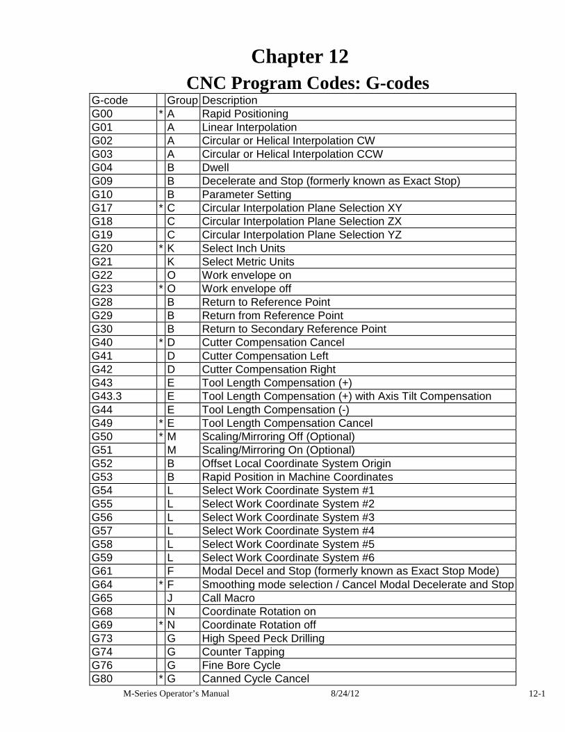
M-Series Operator’s Manual 8/24/12 12-1
Chapter 12 CNC Program Codes: G-codes
G-code Group Description G00 * A Rapid Positioning G01 A Linear Interpolation G02 A Circular or Helical Interpolation CW G03 A Circular or Helical Interpolation CCW G04 B Dwell G09 B Decelerate and Stop (formerly known as Exact Stop) G10 B Parameter Setting G17 * C Circular Interpolation Plane Selection XY G18 C Circular Interpolation Plane Selection ZX G19 C Circular Interpolation Plane Selection YZ G20 * K Select Inch Units G21 K Select Metric Units G22 O Work envelope on G23 * O Work envelope off G28 B Return to Reference Point G29 B Return from Reference Point G30 B Return to Secondary Reference Point G40 * D Cutter Compensation Cancel G41 D Cutter Compensation Left G42 D Cutter Compensation Right G43 E Tool Length Compensation (+) G43.3 E Tool Length Compensation (+) with Axis Tilt Compensation G44 E Tool Length Compensation (-) G49 * E Tool Length Compensation Cancel G50 * M Scaling/Mirroring Off (Optional) G51 M Scaling/Mirroring On (Optional) G52 B Offset Local Coordinate System Origin G53 B Rapid Position in Machine Coordinates G54 L Select Work Coordinate System #1 G55 L Select Work Coordinate System #2 G56 L Select Work Coordinate System #3 G57 L Select Work Coordinate System #4 G58 L Select Work Coordinate System #5 G59 L Select Work Coordinate System #6 G61 F Modal Decel and Stop (formerly known as Exact Stop Mode) G64 * F Smoothing mode selection / Cancel Modal Decelerate and Stop G65 J Call Macro G68 N Coordinate Rotation on G69 * N Coordinate Rotation off G73 G High Speed Peck Drilling G74 G Counter Tapping G76 G Fine Bore Cycle G80 * G Canned Cycle Cancel
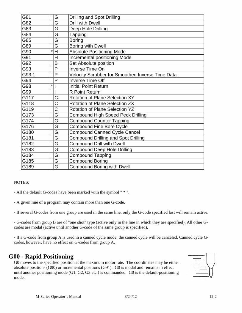
M-Series Operator’s Manual 8/24/12 12-2
G81 G Drilling and Spot Drilling G82 G Drill with Dwell G83 G Deep Hole Drilling G84 G Tapping G85 G Boring G89 G Boring with Dwell G90 * H Absolute Positioning Mode G91 H Incremental positioning Mode G92 B Set Absolute position G93 P Inverse Time On G93.1 P Velocity Scrubber for Smoothed Inverse Time Data G94 P Inverse Time Off G98 * I Initial Point Return G99 I R Point Return G117 C Rotation of Plane Selection XY G118 C Rotation of Plane Selection ZX G119 C Rotation of Plane Selection YZ G173 G Compound High Speed Peck Drilling G174 G Compound Counter Tapping G176 G Compound Fine Bore Cycle G180 G Compound Canned Cycle Cancel G181 G Compound Drilling and Spot Drilling G182 G Compound Drill with Dwell G183 G Compound Deep Hole Drilling G184 G Compound Tapping G185 G Compound Boring G189 G Compound Boring with Dwell
NOTES: - All the default G-codes have been marked with the symbol " * ". - A given line of a program may contain more than one G-code. - If several G-codes from one group are used in the same line, only the G-code specified last will remain active. - G-codes from group B are of "one shot" type (active only in the line in which they are specified). All other G-codes are modal (active until another G-code of the same group is specified). - If a G-code from group A is used in a canned cycle mode, the canned cycle will be canceled. Canned cycle G-codes, however, have no effect on G-codes from group A.
G00 - Rapid Positioning G0 moves to the specified position at the maximum motor rate. The coordinates may be either absolute positions (G90) or incremental positions (G91). G0 is modal and remains in effect until another positioning mode (G1, G2, G3 etc.) is commanded. G0 is the default-positioning mode.
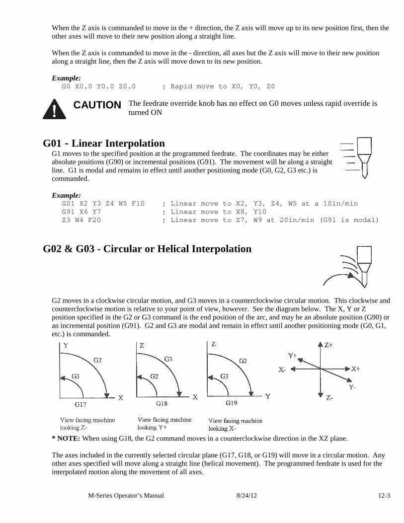
M-Series Operator’s Manual 8/24/12 12-3
When the Z axis is commanded to move in the + direction, the Z axis will move up to its new position first, then the other axes will move to their new position along a straight line. When the Z axis is commanded to move in the - direction, all axes but the Z axis will move to their new position along a straight line, then the Z axis will move down to its new position. Example:
G0 X0.0 Y0.0 Z0.0 ; Rapid move to X0, Y0, Z0
CAUTION The feedrate override knob has no effect on G0 moves unless rapid override is
turned ON
G01 - Linear Interpolation G1 moves to the specified position at the programmed feedrate. The coordinates may be either absolute positions (G90) or incremental positions (G91). The movement will be along a straight line. G1 is modal and remains in effect until another positioning mode (G0, G2, G3 etc.) is commanded. Example:
G01 X2 Y3 Z4 W5 F10 ; Linear move to X2, Y3, Z4, W5 at a 10in/min G91 X6 Y7 ; Linear move to X8, Y10 Z3 W4 F20 ; Linear move to Z7, W9 at 20in/min (G91 is modal)
G02 & G03 - Circular or Helical Interpolation
G2 moves in a clockwise circular motion, and G3 moves in a counterclockwise circular motion. This clockwise and counterclockwise motion is relative to your point of view, however. See the diagram below. The X, Y or Z position specified in the G2 or G3 command is the end position of the arc, and may be an absolute position (G90) or an incremental position (G91). G2 and G3 are modal and remain in effect until another positioning mode (G0, G1, etc.) is commanded.
* NOTE: When using G18, the G2 command moves in a counterclockwise direction in the XZ plane. The axes included in the currently selected circular plane (G17, G18, or G19) will move in a circular motion. Any other axes specified will move along a straight line (helical movement). The programmed feedrate is used for the interpolated motion along the movement of all axes.
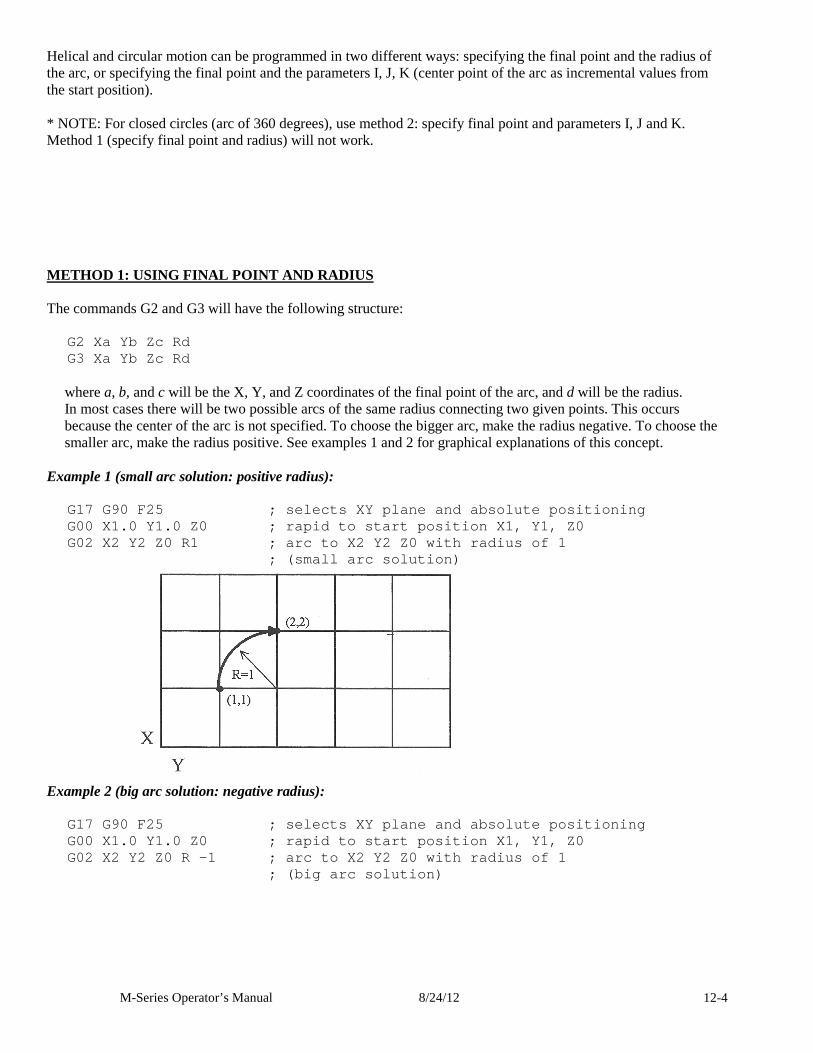
M-Series Operator’s Manual 8/24/12 12-4
Helical and circular motion can be programmed in two different ways: specifying the final point and the radius of the arc, or specifying the final point and the parameters I, J, K (center point of the arc as incremental values from the start position). * NOTE: For closed circles (arc of 360 degrees), use method 2: specify final point and parameters I, J and K. Method 1 (specify final point and radius) will not work. METHOD 1: USING FINAL POINT AND RADIUS The commands G2 and G3 will have the following structure:
G2 Xa Y b Z c R d G3 Xa Y b Z c R d
where a, b, and c will be the X, Y, and Z coordinates of the final point of the arc, and d will be the radius. In most cases there will be two possible arcs of the same radius connecting two given points. This occurs because the center of the arc is not specified. To choose the bigger arc, make the radius negative. To choose the smaller arc, make the radius positive. See examples 1 and 2 for graphical explanations of this concept.
Example 1 (small arc solution: positive radius):
G17 G90 F25 ; selects XY plane and absolute positio ning G00 X1.0 Y1.0 Z0 ; rapid to start position X1, Y1, Z0 G02 X2 Y2 Z0 R1 ; arc to X2 Y2 Z0 with radius of 1 ; (small arc solution)
Example 2 (big arc solution: negative radius):
G17 G90 F25 ; selects XY plane and absolute positio ning G00 X1.0 Y1.0 Z0 ; rapid to start position X1, Y1, Z0 G02 X2 Y2 Z0 R -1 ; arc to X2 Y2 Z0 with radius of 1 ; (big arc solution)
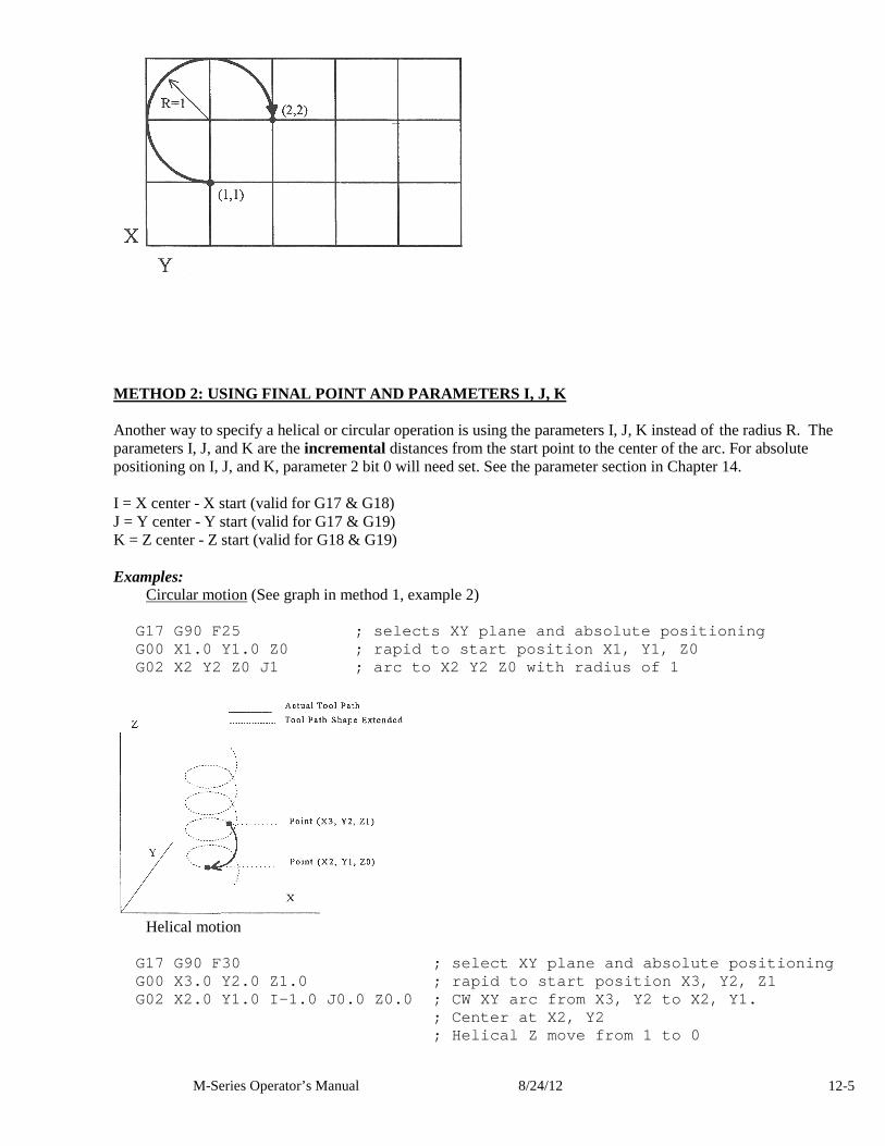
M-Series Operator’s Manual 8/24/12 12-5
METHOD 2: USING FINAL POINT AND PARAMETERS I, J, K Another way to specify a helical or circular operation is using the parameters I, J, K instead of the radius R. The parameters I, J, and K are the incremental distances from the start point to the center of the arc. For absolute positioning on I, J, and K, parameter 2 bit 0 will need set. See the parameter section in Chapter 14. I = X center - X start (valid for G17 & G18) J = Y center - Y start (valid for G17 & G19) K = Z center - Z start (valid for G18 & G19) Examples: Circular motion (See graph in method 1, example 2)
G17 G90 F25 ; selects XY plane and absolute positio ning G00 X1.0 Y1.0 Z0 ; rapid to start position X1, Y1, Z0 G02 X2 Y2 Z0 J1 ; arc to X2 Y2 Z0 with radius of 1
Helical motion
G17 G90 F30 ; select XY plane and absolute position ing G00 X3.0 Y2.0 Z1.0 ; rapid to start position X3, Y2 , Z1 G02 X2.0 Y1.0 I-1.0 J0.0 Z0.0 ; CW XY arc from X3, Y2 to X2, Y1. ; Center at X2, Y2 ; Helical Z move from 1 to 0
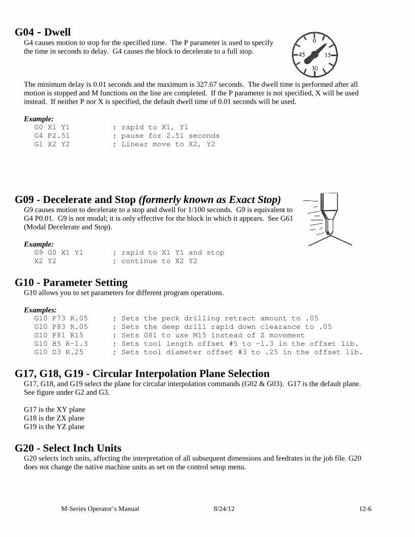
M-Series Operator’s Manual 8/24/12 12-6
G04 - Dwell G4 causes motion to stop for the specified time. The P parameter is used to specify the time in seconds to delay. G4 causes the block to decelerate to a full stop.
The minimum delay is 0.01 seconds and the maximum is 327.67 seconds. The dwell time is performed after all motion is stopped and M functions on the line are completed. If the P parameter is not specified, X will be used instead. If neither P nor X is specified, the default dwell time of 0.01 seconds will be used. Example:
G0 X1 Y1 ; rapid to X1, Y1 G4 P2.51 ; pause for 2.51 seconds G1 X2 Y2 ; Linear move to X2, Y2
G09 - Decelerate and Stop (formerly known as Exact Stop) G9 causes motion to decelerate to a stop and dwell for 1/100 seconds. G9 is equivalent to G4 P0.01. G9 is not modal; it is only effective for the block in which it appears. See G61 (Modal Decelerate and Stop). Example:
G9 G0 X1 Y1 ; rapid to X1 Y1 and stop X2 Y2 ; continue to X2 Y2
G10 - Parameter Setting G10 allows you to set parameters for different program operations. Examples:
G10 P73 R.05 ; Sets the peck drilling retract amoun t to .05 G10 P83 R.05 ; Sets the deep drill rapid down clear ance to .05 G10 P81 R15 ; Sets G81 to use M15 instead of Z mov ement G10 H5 R-1.3 ; Sets tool length offset #5 to -1.3 i n the offset lib. G10 D3 R.25 ; Sets tool diameter offset #3 to .25 in the offset lib.
G17, G18, G19 - Circular Interpolation Plane Selection G17, G18, and G19 select the plane for circular interpolation commands (G02 & G03). G17 is the default plane. See figure under G2 and G3. G17 is the XY plane G18 is the ZX plane G19 is the YZ plane
G20 - Select Inch Units G20 selects inch units, affecting the interpretation of all subsequent dimensions and feedrates in the job file. G20 does not change the native machine units as set on the control setup menu.
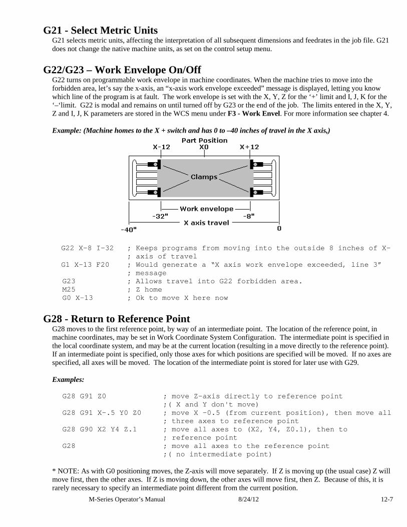
M-Series Operator’s Manual 8/24/12 12-7
G21 - Select Metric Units G21 selects metric units, affecting the interpretation of all subsequent dimensions and feedrates in the job file. G21 does not change the native machine units, as set on the control setup menu.
G22/G23 – Work Envelope On/Off G22 turns on programmable work envelope in machine coordinates. When the machine tries to move into the forbidden area, let’s say the x-axis, an “x-axis work envelope exceeded” message is displayed, letting you know which line of the program is at fault. The work envelope is set with the X, Y, Z for the ‘+’ limit and I, J, K for the ‘–‘limit. G22 is modal and remains on until turned off by G23 or the end of the job. The limits entered in the X, Y, Z and I, J, K parameters are stored in the WCS menu under F3 - Work Envel. For more information see chapter 4. Example: (Machine homes to the X + switch and has 0 to –40 inches of travel in the X axis,)
G22 X-8 I-32 ; Keeps programs from moving into th e outside 8 inches of X-
; axis of travel G1 X-13 F20 ; Would generate a “X axis work enve lope exceeded, line 3” ; message G23 ; Allows travel into G22 forbidden a rea. M25 ; Z home G0 X-13 ; Ok to move X here now
G28 - Return to Reference Point G28 moves to the first reference point, by way of an intermediate point. The location of the reference point, in machine coordinates, may be set in Work Coordinate System Configuration. The intermediate point is specified in the local coordinate system, and may be at the current location (resulting in a move directly to the reference point). If an intermediate point is specified, only those axes for which positions are specified will be moved. If no axes are specified, all axes will be moved. The location of the intermediate point is stored for later use with G29. Examples:
G28 G91 Z0 ; move Z-axis directly to refere nce point ;( X and Y don't move) G28 G91 X-.5 Y0 Z0 ; move X -0.5 (from current posi tion), then move all
; three axes to reference point G28 G90 X2 Y4 Z.1 ; move all axes to (X2, Y4, Z0.1 ), then to ; reference point G28 ; move all axes to the reference point ;( no intermediate point)
* NOTE: As with G0 positioning moves, the Z-axis will move separately. If Z is moving up (the usual case) Z will move first, then the other axes. If Z is moving down, the other axes will move first, then Z. Because of this, it is rarely necessary to specify an intermediate point different from the current position.
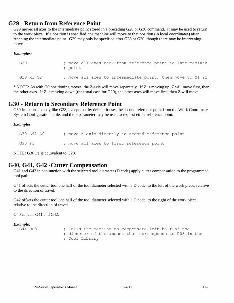
M-Series Operator’s Manual 8/24/12 12-8
G29 - Return from Reference Point G29 moves all axes to the intermediate point stored in a preceding G28 or G30 command. It may be used to return to the work piece. If a position is specified, the machine will move to that position (in local coordinates) after reaching the intermediate point. G29 may only be specified after G28 or G30, though there may be intervening moves. Examples:
G29 ; move all axes back from reference point to in termediate ; point
G29 X1 Y2 ; move all axes to intermediate point, t hen move to X1 Y2
* NOTE: As with G0 positioning moves, the Z-axis will move separately. If Z is moving up, Z will move first, then the other axes. If Z is moving down (the usual case for G29), the other axes will move first, then Z will move.
G30 - Return to Secondary Reference Point G30 functions exactly like G28, except that by default it uses the second reference point from the Work Coordinate System Configuration table, and the P parameter may be used to request either reference point. Examples:
G30 G91 Z0 ; move Z axis directly to second refere nce point G30 P1 ; move all axes to first reference point
NOTE: G30 P1 is equivalent to G28.
G40, G41, G42 -Cutter Compensation G41 and G42 in conjunction with the selected tool diameter (D code) apply cutter compensation to the programmed tool path. G41 offsets the cutter tool one half of the tool diameter selected with a D code, to the left of the work piece, relative to the direction of travel. G42 offsets the cutter tool one half of the tool diameter selected with a D code, to the right of the work piece, relative to the direction of travel. G40 cancels G41 and G42. Example:
G41 D03 ; Tells the machine to compensate left hal f of the ; diameter of the amount that corresponds to D0 3 in the ; Tool Library
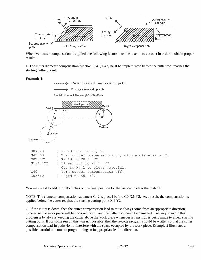
M-Series Operator’s Manual 8/24/12 12-9
Whenever cutter compensation is applied, the following factors must be taken into account in order to obtain proper results. 1. The cutter diameter compensation function (G41, G42) must be implemented before the cutter tool reaches the starting cutting point. Example 1:
G0X0Y0 ; Rapid tool to X0, Y0 G42 D3 ; Turn cutter compensation on, with a diame ter of D3 G0X.5Y2 ; Rapid to X0.5, Y2 G1x4.1Y2 ; Linear cut to X4.1, Y2. ; Cut to X4.1 to clear material. G40 ; Turn cutter compensation off. G0X5Y0 ; Rapid to X5, Y0.
You may want to add .1 or .05 inches on the final position for the last cut to clear the material. NOTE: The diameter compensation statement G42 is placed before G0 X.5 Y2. As a result, the compensation is applied before the cutter reaches the starting cutting point X.5 Y2. 2. If the cutter is down, then the cutter compensation lead-in must always come from an appropriate direction. Otherwise, the work piece will be incorrectly cut, and the cutter tool could be damaged. One way to avoid this problem is by always keeping the cutter above the work piece whenever a transition is being made to a new starting cutting point. If for some reason this was not possible, then the G-code program should be written so that the cutter compensation lead-in paths do not interfere with the space occupied by the work piece. Example 2 illustrates a possible harmful outcome of programming an inappropriate lead-in direction.
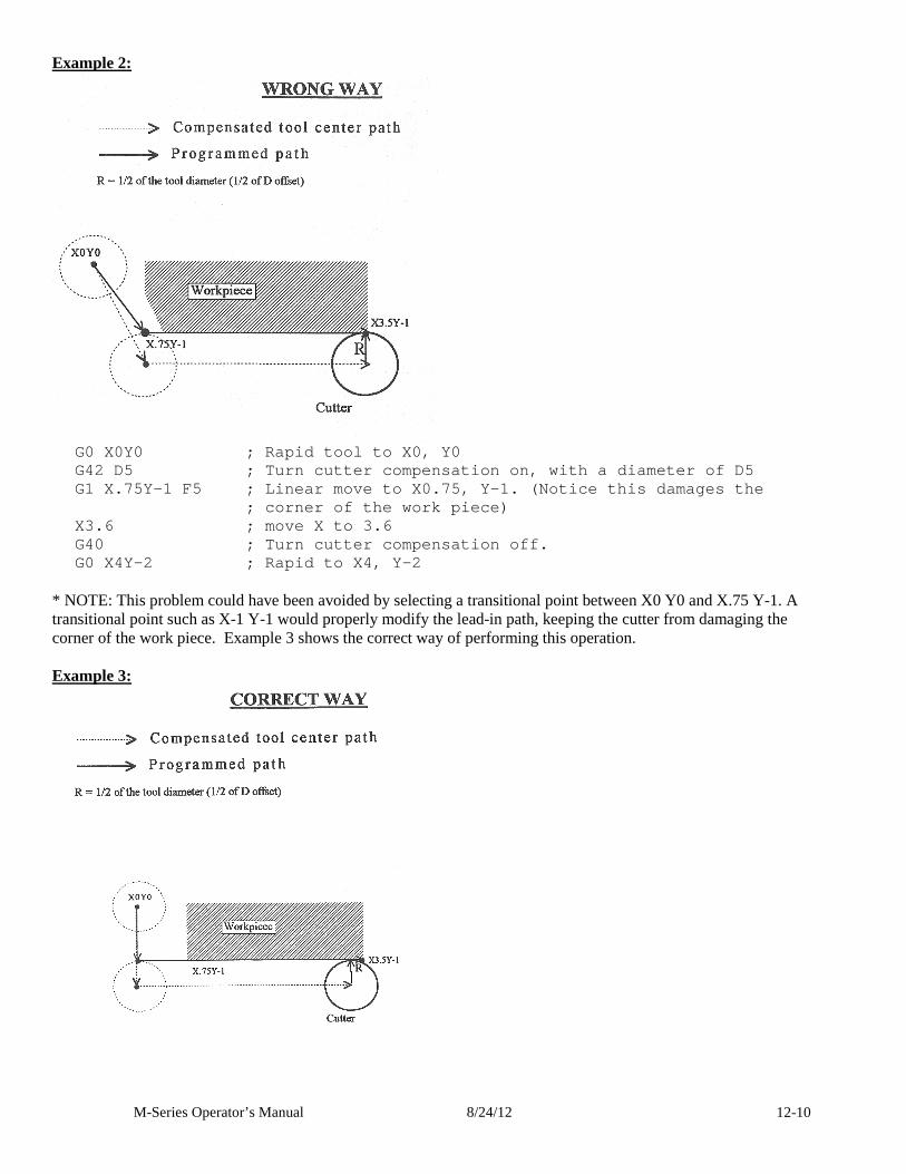
M-Series Operator’s Manual 8/24/12 12-10
Example 2:
G0 X0Y0 ; Rapid tool to X0, Y0 G42 D5 ; Turn cutter compensation on, with a diam eter of D5 G1 X.75Y-1 F5 ; Linear move to X0.75, Y-1. (Notice this damages the
; corner of the work piece) X3.6 ; move X to 3.6 G40 ; Turn cutter compensation off. G0 X4Y-2 ; Rapid to X4, Y-2
* NOTE: This problem could have been avoided by selecting a transitional point between X0 Y0 and X.75 Y-1. A transitional point such as X-1 Y-1 would properly modify the lead-in path, keeping the cutter from damaging the corner of the work piece. Example 3 shows the correct way of performing this operation. Example 3:
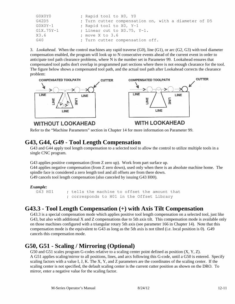
M-Series Operator’s Manual 8/24/12 12-11
G0X0Y0 ; Rapid tool to X0, Y0 G42D5 ; Turn cutter compensation on, with a diame ter of D5 G0X0Y-1 ; Rapid tool to X0, Y-1 G1X.75Y-1 ; Linear cut to X0.75, Y-1. X3.6 ; move X to 3.6 G40 ; Turn cutter compensation off.
3. Lookahead. When the control machines any rapid traverse (G0), line (G1), or arc (G2, G3) with tool diameter compensation enabled, the program will look up to N consecutive events ahead of the current event in order to anticipate tool path clearance problems, where N is the number set in Parameter 99. Lookahead ensures that compensated tool paths don't overlap in programmed part sections where there is not enough clearance for the tool. The figure below shows a compensated tool path, and the actual tool path after Lookahead corrects the clearance problem:
Refer to the “Machine Parameters” section in Chapter 14 for more information on Parameter 99.
G43, G44, G49 - Tool Length Compensation G43 and G44 apply tool length compensation to a selected tool to allow the control to utilize multiple tools in a single CNC program. G43 applies positive compensation (from Z zero up). Work from part surface up. G44 applies negative compensation (from Z zero down), used only when there is an absolute machine home. The spindle face is considered a zero length tool and all offsets are from there down. G49 cancels tool length compensation (also canceled by issuing G43 H00). Example:
G43 H01 ; tells the machine to offset the amount th at ; corresponds to H01 in the Offset Library
G43.3 - Tool Length Compensation (+) with Axis Tilt Compensation G43.3 is a special compensation mode which applies positive tool length compensation on a selected tool, just like G43, but also with additional X and Z compensations due to 5th axis tilt. This compensation mode is available only on those machines configured with a triangular rotary 5th axis (see parameter 166 in Chapter 14). Note that this compensation mode is the equivalent to G43 as long as the 5th axis is not tilted (i.e. local position is 0). G49 cancels this compensation mode.
G50, G51 - Scaling / Mirroring (Optional) G50 and G51 scales program G-codes relative to a scaling center point defined as position (X, Y, Z). A G51 applies scaling/mirror to all positions, lines, and arcs following this G-code, until a G50 is entered. Specify scaling factors with a value I, J, K. The X, Y, and Z parameters are the coordinates of the scaling center. If the scaling center is not specified, the default scaling center is the current cutter position as shown on the DRO. To mirror, enter a negative value for the scaling factor.
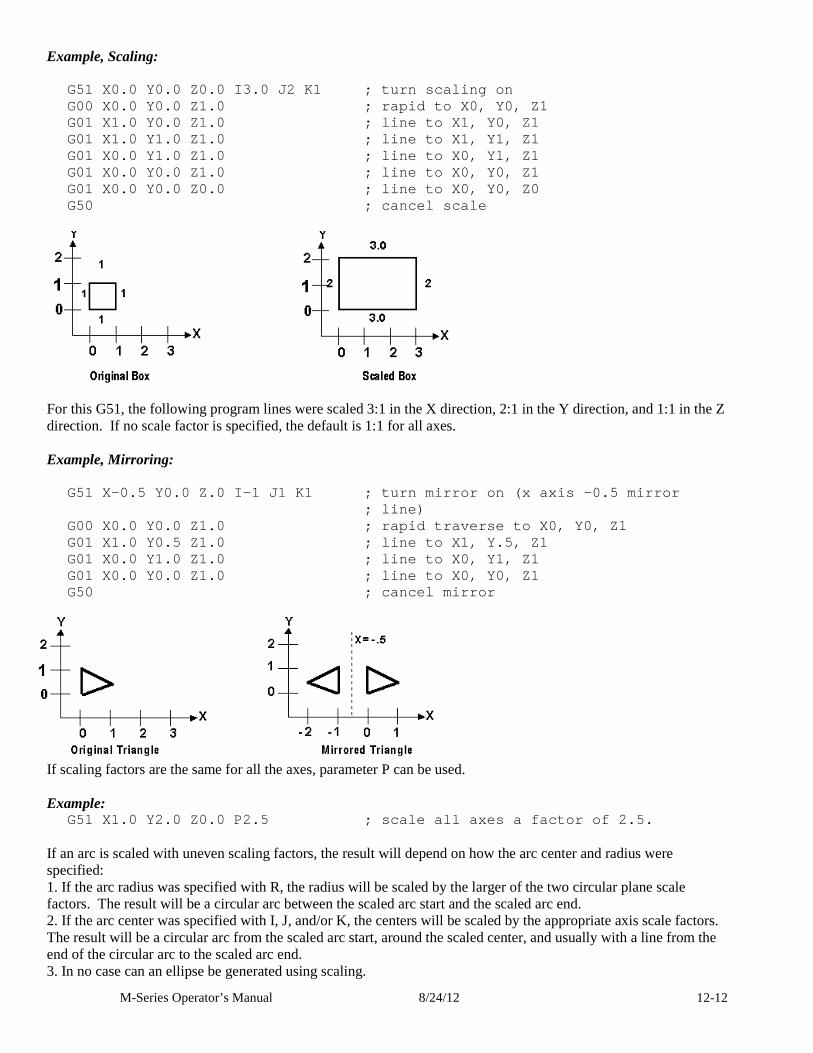
M-Series Operator’s Manual 8/24/12 12-12
Example, Scaling:
G51 X0.0 Y0.0 Z0.0 I3.0 J2 K1 ; turn scaling on G00 X0.0 Y0.0 Z1.0 ; rapid to X0, Y0, Z1 G01 X1.0 Y0.0 Z1.0 ; line to X1, Y0, Z1 G01 X1.0 Y1.0 Z1.0 ; line to X1, Y1, Z1 G01 X0.0 Y1.0 Z1.0 ; line to X0, Y1, Z1 G01 X0.0 Y0.0 Z1.0 ; line to X0, Y0, Z1 G01 X0.0 Y0.0 Z0.0 ; line to X0, Y0, Z0 G50 ; cancel scale
For this G51, the following program lines were scaled 3:1 in the X direction, 2:1 in the Y direction, and 1:1 in the Z direction. If no scale factor is specified, the default is 1:1 for all axes. Example, Mirroring:
G51 X-0.5 Y0.0 Z.0 I-1 J1 K1 ; turn mirror on (x axis -0.5 mirror ; line)
G00 X0.0 Y0.0 Z1.0 ; rapid traverse to X0, Y 0, Z1 G01 X1.0 Y0.5 Z1.0 ; line to X1, Y.5, Z1 G01 X0.0 Y1.0 Z1.0 ; line to X0, Y1, Z1 G01 X0.0 Y0.0 Z1.0 ; line to X0, Y0, Z1 G50 ; cancel mirror
If scaling factors are the same for all the axes, parameter P can be used. Example:
G51 X1.0 Y2.0 Z0.0 P2.5 ; scale all axes a factor of 2.5. If an arc is scaled with uneven scaling factors, the result will depend on how the arc center and radius were specified: 1. If the arc radius was specified with R, the radius will be scaled by the larger of the two circular plane scale factors. The result will be a circular arc between the scaled arc start and the scaled arc end. 2. If the arc center was specified with I, J, and/or K, the centers will be scaled by the appropriate axis scale factors. The result will be a circular arc from the scaled arc start, around the scaled center, and usually with a line from the end of the circular arc to the scaled arc end. 3. In no case can an ellipse be generated using scaling.
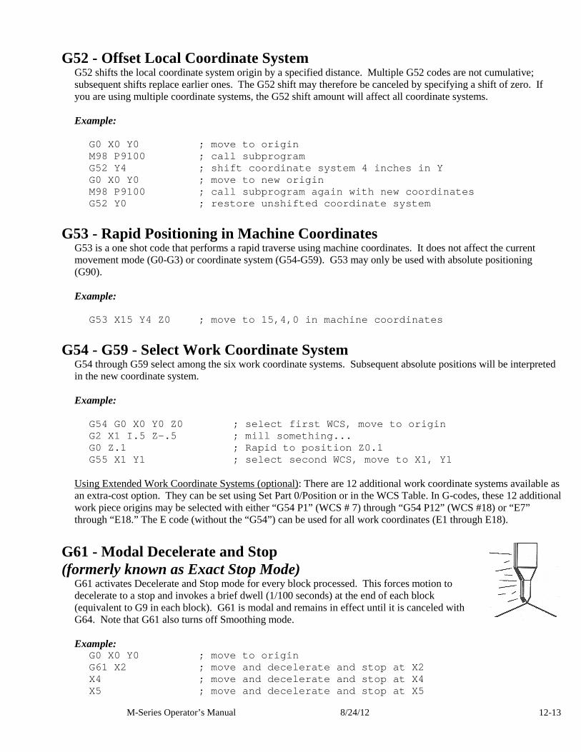
M-Series Operator’s Manual 8/24/12 12-13
G52 - Offset Local Coordinate System G52 shifts the local coordinate system origin by a specified distance. Multiple G52 codes are not cumulative; subsequent shifts replace earlier ones. The G52 shift may therefore be canceled by specifying a shift of zero. If you are using multiple coordinate systems, the G52 shift amount will affect all coordinate systems. Example:
G0 X0 Y0 ; move to origin M98 P9100 ; call subprogram G52 Y4 ; shift coordinate system 4 inches in Y G0 X0 Y0 ; move to new origin M98 P9100 ; call subprogram again with new coordin ates G52 Y0 ; restore unshifted coordinate system
G53 - Rapid Positioning in Machine Coordinates G53 is a one shot code that performs a rapid traverse using machine coordinates. It does not affect the current movement mode (G0-G3) or coordinate system (G54-G59). G53 may only be used with absolute positioning (G90). Example:
G53 X15 Y4 Z0 ; move to 15,4,0 in machine coordinat es
G54 - G59 - Select Work Coordinate System G54 through G59 select among the six work coordinate systems. Subsequent absolute positions will be interpreted in the new coordinate system. Example:
G54 G0 X0 Y0 Z0 ; select first WCS, move to origin G2 X1 I.5 Z-.5 ; mill something... G0 Z.1 ; Rapid to position Z0.1 G55 X1 Y1 ; select second WCS, move to X1, Y1
Using Extended Work Coordinate Systems (optional): There are 12 additional work coordinate systems available as an extra-cost option. They can be set using Set Part 0/Position or in the WCS Table. In G-codes, these 12 additional work piece origins may be selected with either “G54 P1” (WCS # 7) through “G54 P12” (WCS #18) or “E7” through “E18.” The E code (without the “G54”) can be used for all work coordinates (E1 through E18).
G61 - Modal Decelerate and Stop (formerly known as Exact Stop Mode)
G61 activates Decelerate and Stop mode for every block processed. This forces motion to decelerate to a stop and invokes a brief dwell (1/100 seconds) at the end of each block (equivalent to G9 in each block). G61 is modal and remains in effect until it is canceled with G64. Note that G61 also turns off Smoothing mode. Example:
G0 X0 Y0 ; move to origin G61 X2 ; move and decelerate and stop at X2 X4 ; move and decelerate and stop at X4 X5 ; move and decelerate and stop at X5
M-Series Operator’s Manual 8/24/12 12-14
G64 – Smoothing Mode Selection / Cancel Modal Decel and Stop Invoking G64 with either an ON or OFF parameter sets the Smoothing mode to on or off, and also cancels Modal Decelerate and Stop (G61). Invoking G64 without either the ON or OFF parameter simply cancels Modal Decelerate and Stop. G64 always cancels G61 no matter what optional parameters appear with G64. The inital on/off state of Smoothing (i.e. at the beginning of a G-code program) is determined by parameter 220. The Smoothing on/off modal state can be changed using a G64 with an ON or OFF parameter and this will be in effect for the rest of the job or until another G64 ON/OFF is encountered. Upon job restart, the inital on/off state of Smoothing will once again be determined by parameter 220.
G64 Parameters Function (none) Cancel Modal Decelerate and Stop (Cancel G61) ON Turn on Smoothing mode and
also cancel Modal Decelerate and Stop. OFF Turn off Smoothing mode and
also cancel Modal Decelerate and Stop. Examples:
G64 ;no optional parameters – only cancel Moda l Decelerate and Stop G64 ON ;turn on modal Smoothing mode (and cancel Modal Decel and Stop) G64 OFF ;turn off modal Smoothing mode (and cancel Modal Decel and Stop)
G65 - Call Macro G65 calls a macro with user-specified values. A macro is a subprogram that executes a certain operation (e.g. drill pattern, contours, etc.) with values assigned to variable parameters within the operation. Calling methods: G65 Pxxxx Lrrrr Arguments or G65 "program.cnc" Lrrrr Arguments where xxxx is the macro number (referring to file Oxxxx.cnc, 0000-9999 allowed, leading zeros required in filename, capital O, lowercase .cnc), rrrr is the repeat value, "program.cnc" is the name of the macro file, and Arguments is a list of variable identifiers and values. Arguments to macro calls are specified by using letters A-Z, excluding G, L, N, O, and P. Macros are written just like normal programs. However, macro programs may access their arguments by using #A, #B, etc., or by using numbers: #1 for A, #2 for B, etc. (exceptions: #4-6 for I-K, #7-11 for D-H). Arguments I, J, and K can be used more than once in a macro call, with the first set of values stored as #4-6, the second as #7-9, etc., to a maximum of 10 sets. * See example at the end of this G65 section. Macros 9100 - 9999 may be embedded into a main program, using O91xx to designate the beginning of the macro and M99 to end it. The CNC software will read the macro and generate a file O91xx.cnc, but will not execute the macro. It will be executed when G65 is issued.
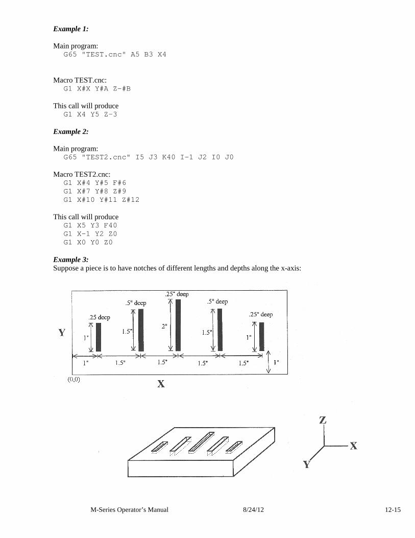
M-Series Operator’s Manual 8/24/12 12-15
Example 1: Main program:
G65 "TEST.cnc" A5 B3 X4 Macro TEST.cnc:
G1 X#X Y#A Z-#B This call will produce
G1 X4 Y5 Z-3 Example 2: Main program:
G65 "TEST2.cnc" I5 J3 K40 I-1 J2 I0 J0 Macro TEST2.cnc:
G1 X#4 Y#5 F#6 G1 X#7 Y#8 Z#9 G1 X#10 Y#11 Z#12
This call will produce
G1 X5 Y3 F40 G1 X-1 Y2 Z0 G1 X0 Y0 Z0
Example 3: Suppose a piece is to have notches of different lengths and depths along the x-axis:
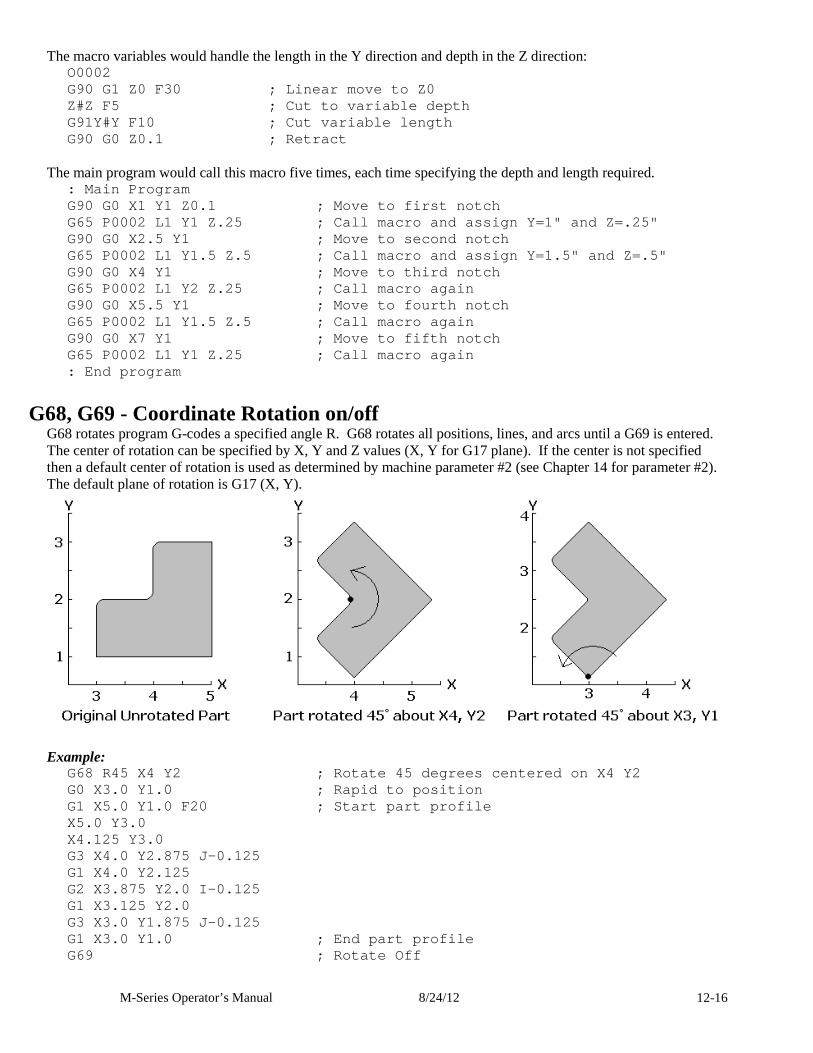
M-Series Operator’s Manual 8/24/12 12-16
The macro variables would handle the length in the Y direction and depth in the Z direction: O0002 G90 G1 Z0 F30 ; Linear move to Z0 Z#Z F5 ; Cut to variable depth G91Y#Y F10 ; Cut variable length G90 G0 Z0.1 ; Retract
The main program would call this macro five times, each time specifying the depth and length required.
: Main Program G90 G0 X1 Y1 Z0.1 ; Move to first notch G65 P0002 L1 Y1 Z.25 ; Call macro and assign Y=1" and Z=.25" G90 G0 X2.5 Y1 ; Move to second notch G65 P0002 L1 Y1.5 Z.5 ; Call macro and assign Y=1. 5" and Z=.5" G90 G0 X4 Y1 ; Move to third notch G65 P0002 L1 Y2 Z.25 ; Call macro again G90 G0 X5.5 Y1 ; Move to fourth notch G65 P0002 L1 Y1.5 Z.5 ; Call macro again G90 G0 X7 Y1 ; Move to fifth notch G65 P0002 L1 Y1 Z.25 ; Call macro again : End program
G68, G69 - Coordinate Rotation on/off G68 rotates program G-codes a specified angle R. G68 rotates all positions, lines, and arcs until a G69 is entered. The center of rotation can be specified by X, Y and Z values (X, Y for G17 plane). If the center is not specified then a default center of rotation is used as determined by machine parameter #2 (see Chapter 14 for parameter #2). The default plane of rotation is G17 (X, Y).
Example:
G68 R45 X4 Y2 ; Rotate 45 degrees centered on X4 Y2 G0 X3.0 Y1.0 ; Rapid to position G1 X5.0 Y1.0 F20 ; Start part profile X5.0 Y3.0 X4.125 Y3.0 G3 X4.0 Y2.875 J-0.125 G1 X4.0 Y2.125 G2 X3.875 Y2.0 I-0.125 G1 X3.125 Y2.0 G3 X3.0 Y1.875 J-0.125 G1 X3.0 Y1.0 ; End part profile G69 ; Rotate Off
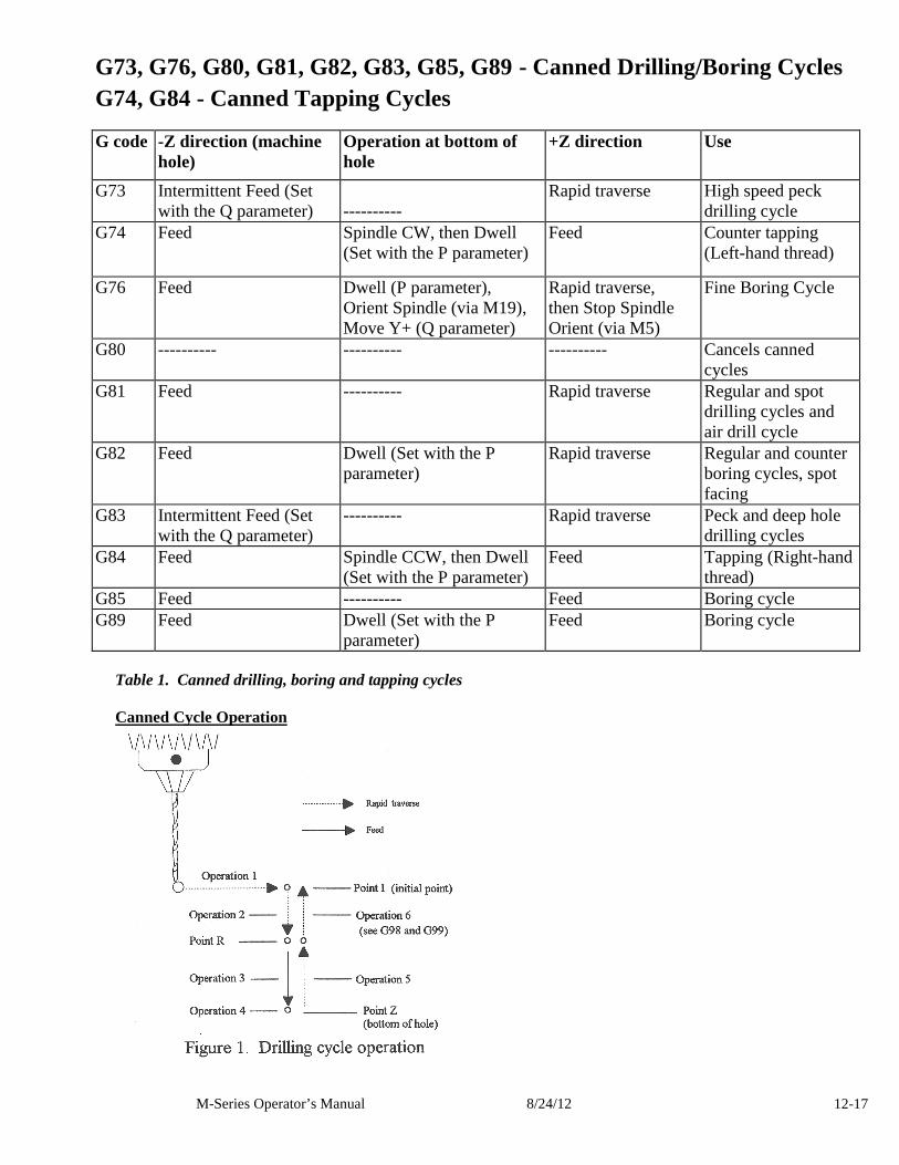
M-Series Operator’s Manual 8/24/12 12-17
G73, G76, G80, G81, G82, G83, G85, G89 - Canned Drilling/Boring Cycles G74, G84 - Canned Tapping Cycles
G code -Z direction (machine
hole) Operation at bottom of hole
+Z direction
Use
G73
Intermittent Feed (Set with the Q parameter)
----------
Rapid traverse High speed peck drilling cycle
G74
Feed
Spindle CW, then Dwell (Set with the P parameter)
Feed Counter tapping (Left-hand thread)
G76 Feed Dwell (P parameter), Orient Spindle (via M19), Move Y+ (Q parameter)
Rapid traverse, then Stop Spindle Orient (via M5)
Fine Boring Cycle
G80 ---------- ---------- ---------- Cancels canned cycles
G81 Feed ---------- Rapid traverse Regular and spot drilling cycles and air drill cycle
G82 Feed Dwell (Set with the P parameter)
Rapid traverse Regular and counter boring cycles, spot facing
G83
Intermittent Feed (Set with the Q parameter)
---------- Rapid traverse Peck and deep hole drilling cycles
G84 Feed Spindle CCW, then Dwell (Set with the P parameter)
Feed Tapping (Right-hand thread)
G85 Feed ---------- Feed Boring cycle G89 Feed Dwell (Set with the P
parameter) Feed Boring cycle
Table 1. Canned drilling, boring and tapping cycles Canned Cycle Operation
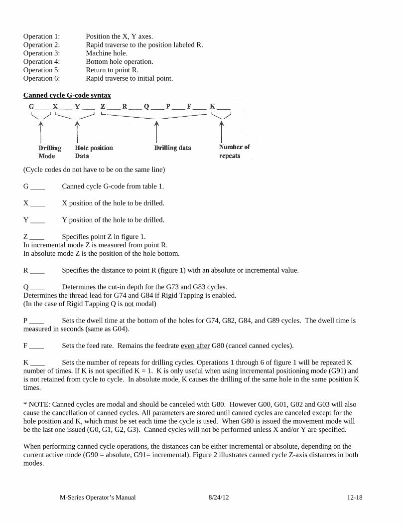
M-Series Operator’s Manual 8/24/12 12-18
Operation 1: Position the X, Y axes. Operation 2: Rapid traverse to the position labeled R. Operation 3: Machine hole. Operation 4: Bottom hole operation. Operation 5: Return to point R. Operation 6: Rapid traverse to initial point. Canned cycle G-code syntax
(Cycle codes do not have to be on the same line) G ____ Canned cycle G-code from table 1. X ____ X position of the hole to be drilled. Y ____ Y position of the hole to be drilled. Z ____ Specifies point Z in figure 1. In incremental mode Z is measured from point R. In absolute mode Z is the position of the hole bottom. R ____ Specifies the distance to point R (figure 1) with an absolute or incremental value. Q ____ Determines the cut-in depth for the G73 and G83 cycles. Determines the thread lead for G74 and G84 if Rigid Tapping is enabled. (In the case of Rigid Tapping Q is not modal) P ____ Sets the dwell time at the bottom of the holes for G74, G82, G84, and G89 cycles. The dwell time is measured in seconds (same as G04). F ____ Sets the feed rate. Remains the feedrate even after G80 (cancel canned cycles). K ____ Sets the number of repeats for drilling cycles. Operations 1 through 6 of figure 1 will be repeated K number of times. If K is not specified K = 1. K is only useful when using incremental positioning mode (G91) and is not retained from cycle to cycle. In absolute mode, K causes the drilling of the same hole in the same position K times. * NOTE: Canned cycles are modal and should be canceled with G80. However G00, G01, G02 and G03 will also cause the cancellation of canned cycles. All parameters are stored until canned cycles are canceled except for the hole position and K, which must be set each time the cycle is used. When G80 is issued the movement mode will be the last one issued (G0, G1, G2, G3). Canned cycles will not be performed unless X and/or Y are specified. When performing canned cycle operations, the distances can be either incremental or absolute, depending on the current active mode (G90 = absolute, G91= incremental). Figure 2 illustrates canned cycle Z-axis distances in both modes.
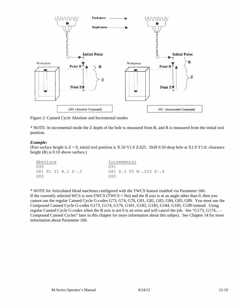
M-Series Operator’s Manual 8/24/12 12-19
Figure 2: Canned Cycle Absolute and Incremental modes * NOTE: In incremental mode the Z depth of the hole is measured from R, and R is measured from the initial tool position. Example: (Part surface height is Z = 0, initial tool position is X.50 Y1.0 Z.625. Drill 0.50 deep hole at X1.0 Y1.0; clearance height (R) is 0.10 above surface.)
Absolute Incremental G90 G91 G81 X1 Y1 R.1 Z-.5 G81 X.5 Y0 R-.525 Z-.6 G80 G80
* NOTE for Articulated Head machines configured with the TWCS feature enabled via Parameter 166: If the currently selected WCS is non-TWCS (TWCS = No) and the B axis is at an angle other than 0, then you cannot use the regular Canned Cycle G-codes G73, G74, G76, G81, G82, G83, G84, G85, G89. You must use the Compound Canned Cycle G-codes G173, G174, G176, G181, G182, G183, G184, G185, G189 instead. Using regular Canned Cycle G-codes when the B axis is not 0 is an error and will cancel the job. See “G173, G174... – Compound Canned Cycles” later in this chapter for more information about this subject. See Chapter 14 for more information about Parameter 166.
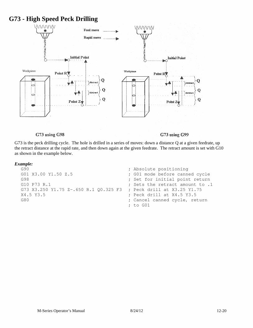
M-Series Operator’s Manual 8/24/12 12-20
G73 - High Speed Peck Drilling
G73 is the peck drilling cycle. The hole is drilled in a series of moves: down a distance Q at a given feedrate, up the retract distance at the rapid rate, and then down again at the given feedrate. The retract amount is set with G10 as shown in the example below. Example:
G90 ; Absolute positioning G01 X3.00 Y1.50 Z.5 ; G01 mode before ca nned cycle G98 ; Set for initial point return G10 P73 R.1 ; Sets the retract amount to .1 G73 X3.250 Y1.75 Z-.650 R.1 Q0.325 F3 ; Peck drill at X3.25 Y1.75 X4.5 Y3.5 ; Peck drill at X4.5 Y3.5 G80 ; Cancel canned cycle, return ; to G01
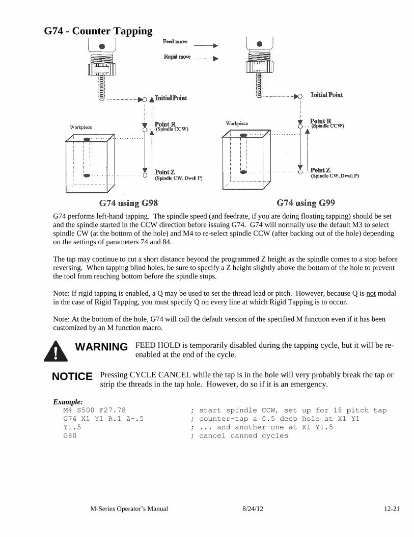
M-Series Operator’s Manual 8/24/12 12-21
G74 - Counter Tapping
G74 performs left-hand tapping. The spindle speed (and feedrate, if you are doing floating tapping) should be set and the spindle started in the CCW direction before issuing G74. G74 will normally use the default M3 to select spindle CW (at the bottom of the hole) and M4 to re-select spindle CCW (after backing out of the hole) depending on the settings of parameters 74 and 84. The tap may continue to cut a short distance beyond the programmed Z height as the spindle comes to a stop before reversing. When tapping blind holes, be sure to specify a Z height slightly above the bottom of the hole to prevent the tool from reaching bottom before the spindle stops. Note: If rigid tapping is enabled, a Q may be used to set the thread lead or pitch. However, because Q is not modal in the case of Rigid Tapping, you must specify Q on every line at which Rigid Tapping is to occur. Note: At the bottom of the hole, G74 will call the default version of the specified M function even if it has been customized by an M function macro.
WARNING FEED HOLD is temporarily disabled during the tapping cycle, but it will be re-
enabled at the end of the cycle.
NOTICE Pressing CYCLE CANCEL while the tap is in the hole will very probably break the tap or strip the threads in the tap hole. However, do so if it is an emergency.
Example:
M4 S500 F27.78 ; start spindle CCW, set up for 18 pitch tap G74 X1 Y1 R.1 Z-.5 ; counter-tap a 0.5 deep hole a t X1 Y1 Y1.5 ; ... and another one at X1 Y1.5 G80 ; cancel canned cycles
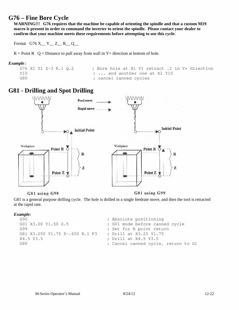
M-Series Operator’s Manual 8/24/12 12-22
G76 – Fine Bore Cycle WARNING!!! G76 requires that the machine be capable of orienting the spindle and that a custom M19 macro is present in order to command the inverter to orient the spindle. Please contact your dealer to confirm that your machine meets these requirements before attempting to use this cycle.
Format G76 X__ Y__ Z__ R__ Q__ R = Point R Q = Distance to pull away from wall in Y+ direction at bottom of hole.
Example:
G76 X1 Y1 Z-3 R.1 Q.2 ; Bore hole at X1 Y1 re tract .2 in Y+ direction Y10 ; ... and another one at X1 Y10 G80 ; cancel canned cycles
G81 - Drilling and Spot Drilling
G81 is a general purpose drilling cycle. The hole is drilled in a single feedrate move, and then the tool is retracted at the rapid rate. Example:
G90 ; Absolute positioning G01 X3.00 Y1.50 Z.5 ; G01 mode before canned cycl e G99 ; Set for R point return G81 X3.250 Y1.75 Z-.650 R.1 F3 ; Drill at X3.25 Y1. 75 X4.5 Y3.5 ; Drill at X4.5 Y3.5 G80 ; Cancel canned cycle, return to G1
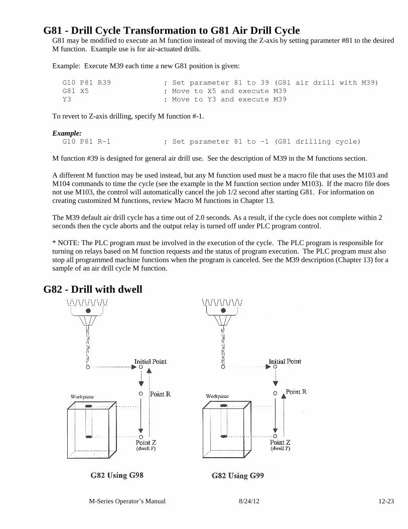
M-Series Operator’s Manual 8/24/12 12-23
G81 - Drill Cycle Transformation to G81 Air Drill C ycle G81 may be modified to execute an M function instead of moving the Z-axis by setting parameter #81 to the desired M function. Example use is for air-actuated drills. Example: Execute M39 each time a new G81 position is given:
G10 P81 R39 ; Set parameter 81 to 39 (G81 air dri ll with M39) G81 X5 ; Move to X5 and execute M39 Y3 ; Move to Y3 and execute M39
To revert to Z-axis drilling, specify M function #-1. Example:
G10 P81 R-1 ; Set parameter 81 to -1 (G81 drillin g cycle) M function #39 is designed for general air drill use. See the description of M39 in the M functions section. A different M function may be used instead, but any M function used must be a macro file that uses the M103 and M104 commands to time the cycle (see the example in the M function section under M103). If the macro file does not use M103, the control will automatically cancel the job 1/2 second after starting G81. For information on creating customized M functions, review Macro M functions in Chapter 13. The M39 default air drill cycle has a time out of 2.0 seconds. As a result, if the cycle does not complete within 2 seconds then the cycle aborts and the output relay is turned off under PLC program control. * NOTE: The PLC program must be involved in the execution of the cycle. The PLC program is responsible for turning on relays based on M function requests and the status of program execution. The PLC program must also stop all programmed machine functions when the program is canceled. See the M39 description (Chapter 13) for a sample of an air drill cycle M function.
G82 - Drill with dwell
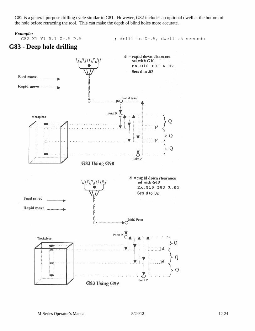
M-Series Operator’s Manual 8/24/12 12-24
G82 is a general purpose drilling cycle similar to G81. However, G82 includes an optional dwell at the bottom of the hole before retracting the tool. This can make the depth of blind holes more accurate. Example:
G82 X1 Y1 R.1 Z-.5 P.5 ; drill to Z-.5, dwell .5 seconds
G83 - Deep hole drilling
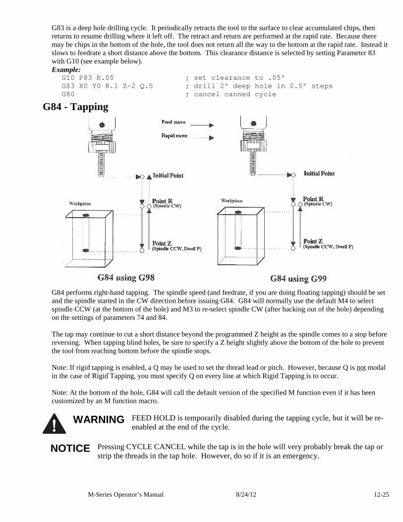
M-Series Operator’s Manual 8/24/12 12-25
G83 is a deep hole drilling cycle. It periodically retracts the tool to the surface to clear accumulated chips, then returns to resume drilling where it left off. The retract and return are performed at the rapid rate. Because there may be chips in the bottom of the hole, the tool does not return all the way to the bottom at the rapid rate. Instead it slows to feedrate a short distance above the bottom. This clearance distance is selected by setting Parameter 83 with G10 (see example below). Example:
G10 P83 R.05 ; set clearance to .05" G83 X0 Y0 R.1 Z-2 Q.5 ; drill 2" deep hole in 0.5" steps G80 ; cancel canned cycle
G84 - Tapping
G84 performs right-hand tapping. The spindle speed (and feedrate, if you are doing floating tapping) should be set and the spindle started in the CW direction before issuing G84. G84 will normally use the default M4 to select spindle CCW (at the bottom of the hole) and M3 to re-select spindle CW (after backing out of the hole) depending on the settings of parameters 74 and 84. The tap may continue to cut a short distance beyond the programmed Z height as the spindle comes to a stop before reversing. When tapping blind holes, be sure to specify a Z height slightly above the bottom of the hole to prevent the tool from reaching bottom before the spindle stops. Note: If rigid tapping is enabled, a Q may be used to set the thread lead or pitch. However, because Q is not modal in the case of Rigid Tapping, you must specify Q on every line at which Rigid Tapping is to occur. Note: At the bottom of the hole, G84 will call the default version of the specified M function even if it has been customized by an M function macro.
WARNING FEED HOLD is temporarily disabled during the tapping cycle, but it will be re-
enabled at the end of the cycle.
NOTICE Pressing CYCLE CANCEL while the tap is in the hole will very probably break the tap or strip the threads in the tap hole. However, do so if it is an emergency.
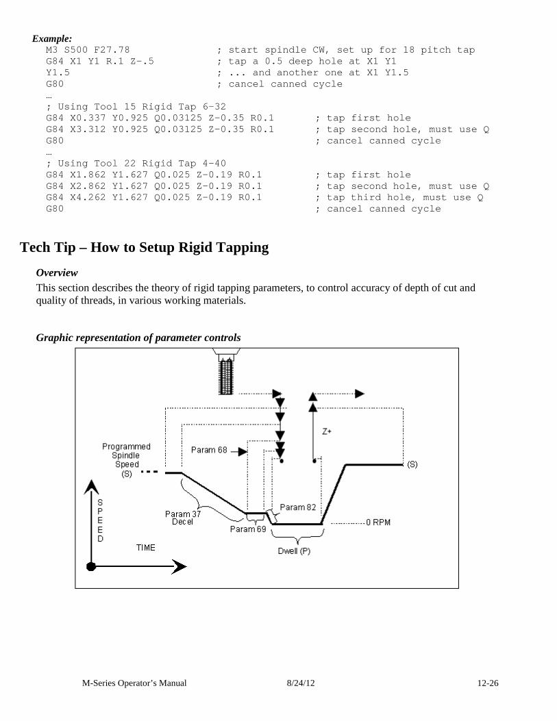
M-Series Operator’s Manual 8/24/12 12-26
Example: M3 S500 F27.78 ; start spindle CW, set up for 18 pitch tap G84 X1 Y1 R.1 Z-.5 ; tap a 0.5 deep hole at X1 Y1 Y1.5 ; ... and another one at X1 Y1.5 G80 ; cancel canned cycle … ; Using Tool 15 Rigid Tap 6-32 G84 X0.337 Y0.925 Q0.03125 Z-0.35 R0.1 ; tap firs t hole G84 X3.312 Y0.925 Q0.03125 Z-0.35 R0.1 ; tap seco nd hole, must use Q G80 ; cancel canned cycle … ; Using Tool 22 Rigid Tap 4-40 G84 X1.862 Y1.627 Q0.025 Z-0.19 R0.1 ; tap first hole G84 X2.862 Y1.627 Q0.025 Z-0.19 R0.1 ; tap second hole, must use Q G84 X4.262 Y1.627 Q0.025 Z-0.19 R0.1 ; tap third hole, must use Q G80 ; cancel canned cycle
Tech Tip – How to Setup Rigid Tapping Overview This section describes the theory of rigid tapping parameters, to control accuracy of depth of cut and quality of threads, in various working materials.
Graphic representation of parameter controls
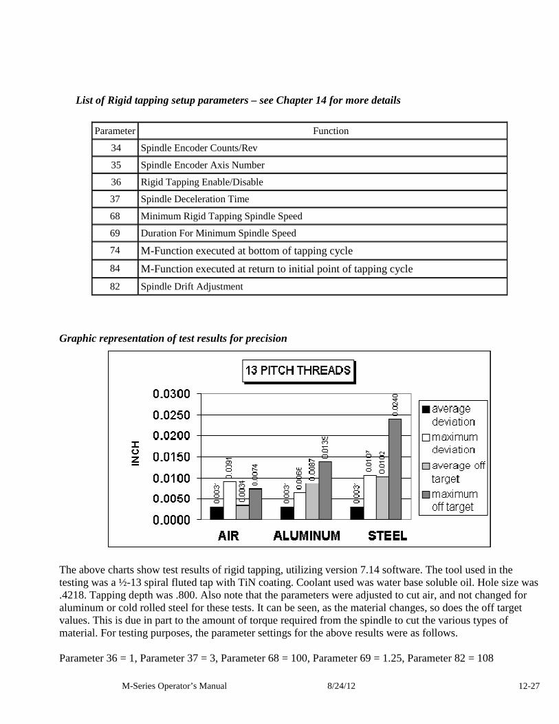
M-Series Operator’s Manual 8/24/12 12-27
List of Rigid tapping setup parameters – see Chapter 14 for more details
Parameter Function
34 Spindle Encoder Counts/Rev
35 Spindle Encoder Axis Number
36 Rigid Tapping Enable/Disable
37 Spindle Deceleration Time
68 Minimum Rigid Tapping Spindle Speed
69 Duration For Minimum Spindle Speed
74 M-Function executed at bottom of tapping cycle
84 M-Function executed at return to initial point of tapping cycle
82 Spindle Drift Adjustment
Graphic representation of test results for precision
The above charts show test results of rigid tapping, utilizing version 7.14 software. The tool used in the testing was a ½-13 spiral fluted tap with TiN coating. Coolant used was water base soluble oil. Hole size was .4218. Tapping depth was .800. Also note that the parameters were adjusted to cut air, and not changed for aluminum or cold rolled steel for these tests. It can be seen, as the material changes, so does the off target values. This is due in part to the amount of torque required from the spindle to cut the various types of material. For testing purposes, the parameter settings for the above results were as follows. Parameter 36 = 1, Parameter 37 = 3, Parameter 68 = 100, Parameter 69 = 1.25, Parameter 82 = 108
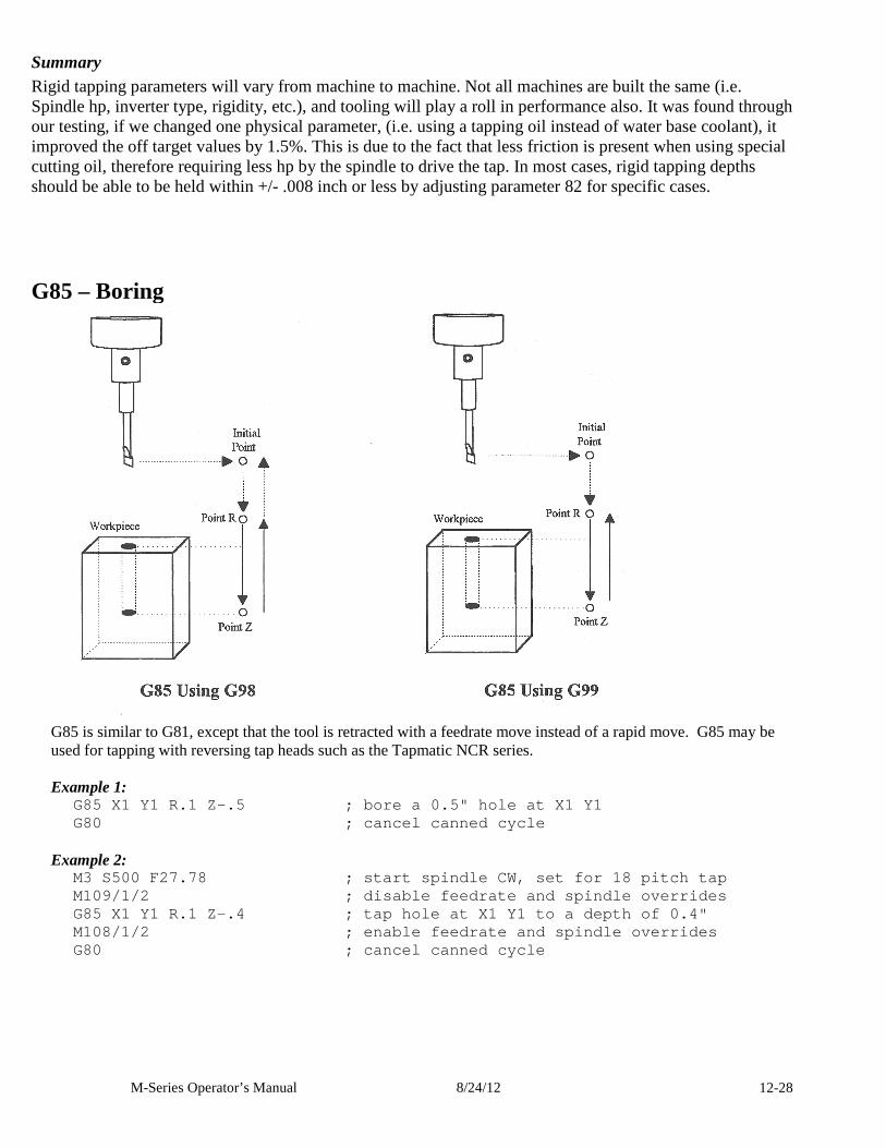
M-Series Operator’s Manual 8/24/12 12-28
Summary Rigid tapping parameters will vary from machine to machine. Not all machines are built the same (i.e. Spindle hp, inverter type, rigidity, etc.), and tooling will play a roll in performance also. It was found through our testing, if we changed one physical parameter, (i.e. using a tapping oil instead of water base coolant), it improved the off target values by 1.5%. This is due to the fact that less friction is present when using special cutting oil, therefore requiring less hp by the spindle to drive the tap. In most cases, rigid tapping depths should be able to be held within +/- .008 inch or less by adjusting parameter 82 for specific cases.
G85 – Boring
G85 is similar to G81, except that the tool is retracted with a feedrate move instead of a rapid move. G85 may be used for tapping with reversing tap heads such as the Tapmatic NCR series. Example 1:
G85 X1 Y1 R.1 Z-.5 ; bore a 0.5" hole at X1 Y1 G80 ; cancel canned cycle
Example 2:
M3 S500 F27.78 ; start spindle CW, set for 18 pit ch tap M109/1/2 ; disable feedrate and spindle override s G85 X1 Y1 R.1 Z-.4 ; tap hole at X1 Y1 to a depth of 0.4" M108/1/2 ; enable feedrate and spindle overrides G80 ; cancel canned cycle
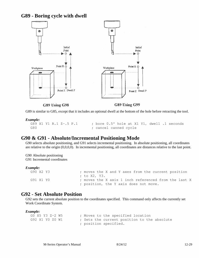
M-Series Operator’s Manual 8/24/12 12-29
G89 - Boring cycle with dwell
G89 is similar to G85, except that it includes an optional dwell at the bottom of the hole before retracting the tool. Example:
G89 X1 Y1 R.1 Z-.5 P.1 ; bore 0.5" hole at X1 Y1, dwell .1 seconds G80 ; cancel canned cycle
G90 & G91 - Absolute/Incremental Positioning Mode G90 selects absolute positioning, and G91 selects incremental positioning. In absolute positioning, all coordinates are relative to the origin (0,0,0,0). In incremental positioning, all coordinates are distances relative to the last point. G90 Absolute positioning G91 Incremental coordinates Example:
G90 X2 Y3 ; moves the X and Y axes from the current position ; to X2, Y3.
G91 X1 Y0 ; moves the X axis 1 inch referenced fr om the last X ; position, the Y axis does not move.
G92 - Set Absolute Position G92 sets the current absolute position to the coordinates specified. This command only affects the currently set Work Coordinate System. Example:
G0 X5 Y3 Z-2 W5 ; Moves to the specified location G92 X1 Y0 Z0 W1 ; Sets the current position to th e absolute ; position specified.
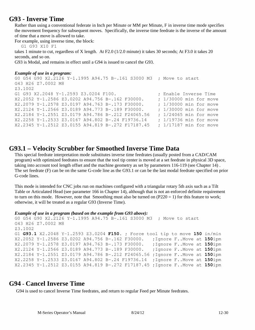
M-Series Operator’s Manual 8/24/12 12-30
G93 - Inverse Time Rather than using a conventional federate in Inch per Minute or MM per Minute, F in inverse time mode specifies the movement frequency for subsequent moves. Specifically, the inverse time feedrate is the inverse of the amount of time that a move is allowed to take. For example, using inverse time, the block:
G1 G93 X10 F1 takes 1 minute to cut, regardless of X length. At F2.0 (1/2.0 minute) it takes 30 seconds; At F3.0 it takes 20 seconds, and so on. G93 is Modal, and remains in effect until a G94 is issued to cancel the G93.
Example of use in a program: G0 G54 G90 X2.2126 Y-1.1995 A94.75 B-.161 S3000 M3 ; Move to start G43 H26 Z7.0002 M8 Z3.1002 G1 G93 X2.2048 Y-1.2593 Z3.0204 F100. ; Enable Inverse Time X2.2052 Y-1.2586 Z3.0202 A94.756 B-.162 F30000. ; 1/30000 min for move X2.2079 Y-1.2578 Z3.0197 A94.763 B-.173 F30000. ; 1/30000 min for move X2.2124 Y-1.2566 Z3.0189 A94.773 B-.189 F30000. ; 1/30000 min for move X2.2184 Y-1.2551 Z3.0179 A94.786 B-.212 F24065.56 ; 1/24065 min for move X2.2258 Y-1.2533 Z3.0167 A94.802 B-.24 F19736.14 ; 1/19736 min for move X2.2345 Y-1.2512 Z3.0155 A94.819 B-.272 F17187.45 ; 1/17187 min for move
G93.1 – Velocity Scrubber for Smoothed Inverse Time Data
This special feedrate interpretation mode substitutes inverse time feedrates (usually posted from a CAD/CAM program) with optimized feedrates to ensure that the tool tip center is moved at a set feedrate in physical 3D space, taking into account tool length offset and the machine geometry as set by parameters 116-119 (see Chapter 14) . The set feedrate (F) can be on the same G-code line as the G93.1 or can be the last modal feedrate specified on prior G-code lines. This mode is intended for CNC jobs run on machines configured with a triangular rotary 5th axis such as a Tilt Table or Articulated Head (see parameter 166 in Chapter 14), although that is not an enforced definite requirement to turn on this mode. However, note that Smoothing must also be turned on (P220 = 1) for this feature to work; otherwise, it will be treated as a regular G93 (Inverse Time).
Example of use in a program (based on the example from G93 above): G0 G54 G90 X2.2126 Y-1.1995 A94.75 B-.161 S3000 M3 ; Move to start G43 H26 Z7.0002 M8 Z3.1002 G1 G93.1 X2.2048 Y-1.2593 Z3.0204 F150. ; Force tool tip to move 150 in/min X2.2052 Y-1.2586 Z3.0202 A94.756 B-.162 F30000. ; Ignore F..Move at 150ipm X2.2079 Y-1.2578 Z3.0197 A94.763 B-.173 F30000. ; Ignore F..Move at 150ipm X2.2124 Y-1.2566 Z3.0189 A94.773 B-.189 F30000. ; Ignore F..Move at 150ipm X2.2184 Y-1.2551 Z3.0179 A94.786 B-.212 F24065.56 ; Ignore F..Move at 150ipm X2.2258 Y-1.2533 Z3.0167 A94.802 B-.24 F19736.14 ; Ignore F..Move at 150ipm X2.2345 Y-1.2512 Z3.0155 A94.819 B-.272 F17187.45 ; Ignore F..Move at 150ipm
G94 - Cancel Inverse Time G94 is used to cancel Inverse Time feedrates, and return to regular Feed per Minute feedrates.
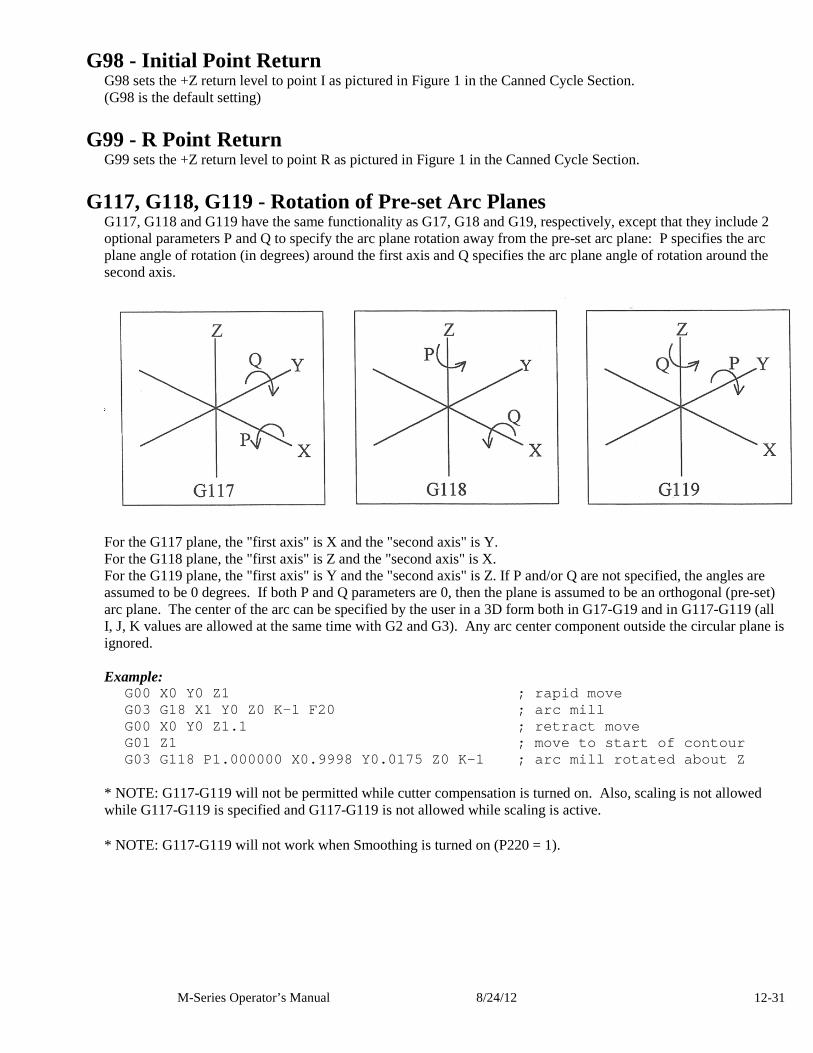
M-Series Operator’s Manual 8/24/12 12-31
G98 - Initial Point Return G98 sets the +Z return level to point I as pictured in Figure 1 in the Canned Cycle Section. (G98 is the default setting)
G99 - R Point Return G99 sets the +Z return level to point R as pictured in Figure 1 in the Canned Cycle Section.
G117, G118, G119 - Rotation of Pre-set Arc Planes G117, G118 and G119 have the same functionality as G17, G18 and G19, respectively, except that they include 2 optional parameters P and Q to specify the arc plane rotation away from the pre-set arc plane: P specifies the arc plane angle of rotation (in degrees) around the first axis and Q specifies the arc plane angle of rotation around the second axis.
For the G117 plane, the "first axis" is X and the "second axis" is Y. For the G118 plane, the "first axis" is Z and the "second axis" is X. For the G119 plane, the "first axis" is Y and the "second axis" is Z. If P and/or Q are not specified, the angles are assumed to be 0 degrees. If both P and Q parameters are 0, then the plane is assumed to be an orthogonal (pre-set) arc plane. The center of the arc can be specified by the user in a 3D form both in G17-G19 and in G117-G119 (all I, J, K values are allowed at the same time with G2 and G3). Any arc center component outside the circular plane is ignored. Example:
G00 X0 Y0 Z1 ; rapid move G03 G18 X1 Y0 Z0 K-1 F20 ; arc mill G00 X0 Y0 Z1.1 ; retract move G01 Z1 ; move to start of contour G03 G118 P1.000000 X0.9998 Y0.0175 Z0 K-1 ; arc mil l rotated about Z
* NOTE: G117-G119 will not be permitted while cutter compensation is turned on. Also, scaling is not allowed while G117-G119 is specified and G117-G119 is not allowed while scaling is active.
* NOTE: G117-G119 will not work when Smoothing is turned on (P220 = 1).
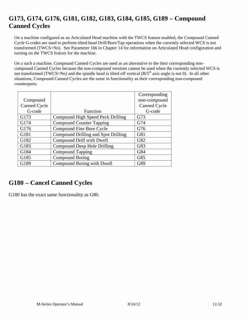
M-Series Operator’s Manual 8/24/12 12-32
G173, G174, G176, G181, G182, G183, G184, G185, G189 – Compound Canned Cycles
On a machine configured as an Articulated Head machine with the TWCS feature enabled, the Compound Canned Cycle G-codes are used to perform tilted-head Drill/Bore/Tap operations when the currently selected WCS is not transformed (TWCS=No). See Parameter 166 in Chapter 14 for information on Articulated Head configuration and turning on the TWCS feature for the machine. On a such a machine, Compound Canned Cycles are used as an alternative to the their corresponding non-compound Canned Cycles because the non-compound versions cannot be used when the currently selected WCS is not transformed (TWCS=No) and the spindle head is tilted off vertical (B/5th axis angle is not 0). In all other situations, Compound Canned Cycles are the same in functionality as their corresponding non-compound counterparts.
Compound Canned Cycle
G-code Function
Corresponding non-compound Canned Cycle
G-code G173 Compound High Speed Peck Drilling G73 G174 Compound Counter Tapping G74 G176 Compound Fine Bore Cycle G76 G181 Compound Drilling and Spot Drilling G81 G182 Compound Drill with Dwell G82 G183 Compound Deep Hole Drilling G83 G184 Compound Tapping G84 G185 Compound Boring G85 G189 Compound Boring with Dwell G89
G180 – Cancel Canned Cycles G180 has the exact same functionality as G80.
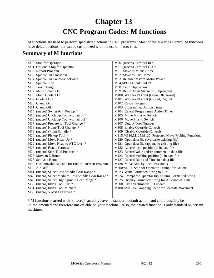
M-Series Operator’s Manual 8/24/12 13-1
Chapter 13 CNC Program Codes: M functions
M functions are used to perform specialized actions in CNC programs. Most of the M-series Control M functions have default actions, but can be customized with the use of macro files.
Summary of M functions M00 Stop for Operator M01 Optional Stop for Operator M02 Restart Program M03 Spindle On Clockwise M04 Spindle On Counterclockwise M05 Spindle Stop M06 Tool Change M07 Mist Coolant On M08 Flood Coolant On M09 Coolant Off M10 Clamp On M11 Clamp Off M14 (macro) Swing Arm Pot Up * M15 (macro) Unclamp Tool with air on * M16 (macro) Unclamp Tool with air off * M17 (macro) Prepare for Tool Change * M18 (macro) Home Tool Changer * M19 (macro) Orient Spindle * M20 (macro) Pickup Tool * M21 (macro) Move Head Up * M22 (macro) Move Head to ATC level * M23 (macro) Rotate Carousel * M24 (macro) Start Tool Put-back * M25 Move to Z Home M26 Set Axis Home M30 Customizable M-code for End of Intercon Program M39 Air Drill M41 (macro) Select Low Spindle Gear Range * M42 (macro) Select Medium-Low Spindle Gear Range * M43 (macro) Select High Spindle Gear Range * M50 (macro) Index Tool Plus * M51 (macro) Index Tool Minus * M60 (macro) 5 Axis Digitizing *
M80 (macro) Carousel In * M81 (macro) Carousel Out * M91 Move to Minus Home M92 Move to Plus Home M93 Release/Restore Motor Power M94,M95 Output On/Off M98 Call Subprogram M99 Return from Macro or Subprogram M100 Wait for PLC bit (Open, Off, Reset) M101 Wait for PLC bit (Closed, On, Set) M102 Restart Program M103 Programmed Action Timer M104 Cancel Programmed Action Timer M105 Move Minus to Switch M106 Move Plus to Switch M107 Output Tool Number M108 Enable Override Controls M109 Disable Override Controls M115,M116,M125,M126 Protected Move Probing Functions M120 Open data file (overwrite existing file) M121 Open data file (append to existing file) M122 Record local position(s) in data file M123 Record value and/or comment in data file M124 Record machine position(s) in data file M127 Record Date and Time in a data file M128 Move Axis by Encoder Counts M200/M201 Stop for Operator, Prompt for Action M223 Write Formatted String to File M224 Prompt for Operator Input Using Formatted String M225 Display Formatted String for A Period of Time M300 Fast Synchronous I/O update M1000-M1015 Graphing Color for Feedrate movement
* M functions marked with “(macro)” actually have no standard default action, and could possibly be unimplemented and therefore unavailable on your machine. Also, their stated function is only standard on certain machines.
M-Series Operator’s Manual 8/24/12 13-2
Macro M functions (custom M functions) Most M-Series CNC M functions from 0 through 90 can be fully customized. Exceptions are M2, M6, and M25 that can be customized, but will always move the 3rd (Z) axis to the home position before executing the macro M function commands. No M functions above 90 may be customized with macros. The default action listed will be performed unless that M function has been customized. To create a macro for an M-function, a file must be created in the C:\cncm directory. The file's name must be mfuncXX.mac where XX is the M function number used to call the macro. M functions 0-9 must use single digits in the filename (e.g. Use mfunc3.mac, not mfunc03.mac). The contents of the file may be any valid M and G codes. Each time the M function is encountered in a program, the macro file will be processed line by line. * NOTE: Nesting of macro M functions is allowed. Recursive calls are not: if a macro M function calls itself, the default action of the function will be executed. Example: Turn on spindle with variable frequency drive and wait for "at speed" response. This example depends on M94/M95 1 being used for the Spindle Enable signal and input 5 being the spindle at speed signal in the PLC program. Create file c:\cncm\mfunc3.mac with contents as follows:
M94/1 ; request spindle start M101/50005 ; wait for up to speed signal
M2, M6, and M25 always move the Z-axis to the home position before any other motion. All other M functions are performed after the motion of the current line is complete. The M and G codes in a macro M function are not usually displayed on the screen as they are executed, and are all treated as one operation in block mode. If you wish to see or step through macro M functions (e.g. for testing purposes), set parameter #10 as follows: 0 Don't display or step through macro M functions 1 Display macro M functions, but don't step through them 2 Display and step through macro M functions * NOTE: You cannot use block mode to step through a macro M function called using the G81 transformation (see Chapter 12); the action timer will expire before you can press CYCLE START . NOTE: Only one M function per line is permitted. * NOTE: Unlike subprograms invoked with G65, macro arguments passed into a macro M function are passed in by reference. This means local changes to #1 through #33 or #A through #Z will change the their values upon return from the macro M function.
M-Series Operator’s Manual 8/24/12 13-3
M00 - Stop for Operator Motion stops, and the operator is prompted to press the CYCLE START button to continue.
M01 - Optional Stop for Operator M1 is an optional pause, whose action can be selected by the operator. When optional stops are turned on, M1 will pause the currently running job until CYCLE START is pressed. However, if optional stops are turned off, M1 will not pause the program. *NOTE: If you plan to override the default action of M1 with a macro file, you may want to include a call to M1 within the macro file so that the default actions of M1 will still be effective in the overridden M1. Otherwise, if a call to M1 is not included within the macro file, the new overridden M1 will cause optional stops to be ineffective.
M02 - Restart Program M2 moves the Z-axis to the home position, performs any movement requested, and restarts the program from the first line. The operator is prompted to press the CYCLE START button to continue.
M03 - Spindle On Clockwise M3 requests the PLC to start the spindle in the clockwise direction. Default action:
M95/2 M94/1
M04 - Spindle On Counterclockwise M4 requests the PLC to start the spindle in the counterclockwise direction. Default action:
M95/1 M94/2
M05 - Spindle Stop M5 requests the PLC to stop the spindle. Default action if the spindle had been spinning CW:
M95/2 M95/1
Default action if the spindle was OFF or was spinning CCW: M95/1 M95/2
M06 - Tool Change M6 moves the Z-axis to the home position and stops the spindle and coolant. If an automatic tool changer is installed, it then commands the tool changer to switch to the requested tool. Otherwise, it prompts the operator to insert the tool and then press the CYCLE START button on the Operator Panel. Default action (no tool changer):
M25 ; always does M25 first M95/1/2/3/5 ; turn off spindle & coolant M100/75 ; wait for CYCLE START button
M-Series Operator’s Manual 8/24/12 13-4
Default action (tool changer installed):
M25 ; always does M25 first M95/1/2/3/5 ; turn off spindle & coolant M95/16 ; turn off tool changer strobe M107 ; send tool number to tool changer M94/16 ; turn on tool changer strobe M101/32 ; wait for acknowledge from changer M95/16 ; turn off tool changer strobe M100/32 ; wait for acknowledge from changer
Manual tool changes are selected by setting Parameter 6 to 0 in the Machine Parameters table. The automatic tool changer is selected by setting Parameter 6 to 1 (see Chapter 14). The PLC program must be involved in commanding an automatic tool changer and its associated strobe, BCD and Acknowledge lines. See Chapter 5 of the service manual for details of how such a PLC program could be constructed.
M07 - Mist Coolant On M7 causes the PLC to start the mist coolant system. Default action:
M95/3 M94/5
M08 - Flood Coolant On M8 causes the PLC to start the flood coolant system. Default action:
M95/5 M94/3
M09 - Coolant Off M9 causes the PLC to stop the coolant system. Default action:
M95/3/5
M10 - Clamp On M10 causes the PLC to activate the clamp. Default action:
M94/4 Note: adding 256 to parameter 178 can switch M10 and M11.
M11 - Clamp Off M11 causes the PLC to release the clamp. Default action:
M95/4
M-Series Operator’s Manual 8/24/12 13-5
M17 – Prepare for Tool Change (Macro) M17 has no default action, therefore a custom M17 macro must be defined for this feature to work. If defined, the M17 macro turns off spindle and coolant and starts the spindle orientation process in preparation for M6 (Tool Change). The M17 macro is allocated for use with Intercon and the setting in Parameter 162. See Parameter 162 in Chapter 14 for more information.
M19 – Spindle Orient (Macro) M19 has no default action, therefore a custom M19 macro must be defined for this feature to work. If defined, the M19 macro sends a request to the PLC to rotate the spindle to its pre-set orient position.
M25 - Move to Z Home M25 moves the Z-axis to the home position at the Z-axis maximum rate. The Z home position defaults to zero in machine coordinates, but may be changed by changing the Z coordinate of the first Reference Point (on the Work Coordinate System Configuration screen). Default action:
G0 <Z home >
M26 - Set Axis Home M26 sets the machine home position for the specified axis to the current position (after the line's movement). If no axis is specified, M26 sets the Z-axis home position. Example:
M91/X ; home X axis to minus home switch M26/X ; set machine home for X-axis there M92/Z ; home Z-axis to plus home switch M26 ; set machine home for Z-axis there
M30 - Custom M Code Intercon posts an M30 at the end of every G code program. By default M30 performs no operation. If you wish to perform certain operations at the end of every program, this M code can be customized to meet you needs. For more information on customizing M codes see the beginning of this chapter.
M39 - Air Drill M39 is a default air drill activation sequence with a timeout. The sequence of operations is as follows:
M94/15 ; activate M function request 15 M103/2 ; start 2 second timer M100/50015 ; wait for input 15 to open M95/15 ; deactivate M function request 15 M104 ; cancel timer
* NOTE: This program will be canceled by timer expiration if input 15 does not open within 2 seconds after M function request 15 is activated. The PLC program must be involved in taking away the drill output when the CNC program stops:
M-Series Operator’s Manual 8/24/12 13-6
Example: ; PLC program fragment CNC_program_running is SV_PROGRAM_RUNNING ;program running indicator M15 is SV_M94_M95_15 ; M function 15 indicator drill_out is OUT5 ; air drill output relay if M15 && CNC_program running then (drill_out) ; Drill On if M94/15 and the ; CNC program is running. Drill ; Off if M95/15 or the CNC ; program is terminated.
M41, M42, M43 – Select Spindle Gear Range (Macros) M41, M42, and M43 have no default actions, and therefore custom macros must be defined for these M codes in order to make this feature work. If defined, these macros notify the PLC of which spindle gear range is selected according to the following table:
Macro M function Action M41 Select Low Gear Range M42 Select Medium-Low Gear Range M43 Select High Gear Range
Note that selecting a “Medium-High” Gear Range is currently not supported by this schema, although that would not prevent a system intergrator from defining another custom macro M function to do that.
M60 – 5-Axis Digitizing Macro
The M60 is used only when digitizing with the 5-Axis Tilt Table system.
The M60 uses user variables to assign a “Start Position” and a “Finish Position” for 5-Axis Digitizing. When the M60 is executed, the probe will be moved from the start position to the end position. If during the motion the probe detects a surface, the surface position is recorded, and the probe returns to the start position. If no surface is found the probe returns to the start position.
The following variables are to be assigned before the M60 is called, the M60 will then use the positions as assigned by the user variables:
#29100 = X-Axis Probing vector start point (Initial Position) #29101 = Y-Axis Probing vector start point (Initial Position) #29102 = Z-Axis Probing vector start point (Initial Position) #29103 = A-Axis Probing vector start point (Initial Position) #29104 = B-Axis Probing vector start point (Initial Position) #29110 = X-Axis Probing vector end point #29111 = Y-Axis Probing vector end point #29112 = Z-Axis Probing vector end point
Upon a successful probe the M60 will use an M122 to save the probed position to a text file that should be opened using an M120 or M121 before calling the M60
M-Series Operator’s Manual 8/24/12 13-7
Example M60 use in a program:
M121 "m60test.dig5" ; Open text file to record data too
#29100 = -8.7999 ; X-Axis Start Position
#29101 = .3747 ; Y-Axis Start Position
#29102 = -1.1832 ; Z-Axis Start Position
#29103 = 85.957 ; A-Axis Start Position
#29104 = 21.36 ; B-Axis Start Position
#29110 = -8.7138 ; X-Axis End Position
#29111 = -.0159 ; Y-Axis End Position
#29112 = -1.183 ; Z-Axis End Position
M60 ; Execute M60
M91 - Move to Minus Home M91 moves to the minus home switch of the axis specified at the slow jog rate for that axis. After the minus home switch is tripped, the axis reverses until the home switch clears, and stops when it detects the index pulse. Example:
M91/X ; moves the X-axis to the minus home switch. G92 X-10 ; sets X minus home switch at -10
M92 - Move to Plus Home M92 moves to the plus home switch of the axis specified at the slow jog rate for that axis. After the plus home switch is tripped, the axis reverses until the home switch clears, and stops when it detects the index pulse. Example:
M92/X ; moves the X-axis to the plus home switch. G92 X+10 ; Sets X plus home switch at +10
M93 – Release/Restore Motor Power M93 releases or restores motor power for the axis specified. If no axis is specified, then all axes are released. Example: To release motor power:
M93/X ; releases the X axis. M93 ; releases the motors on all axes.
Example: To restore power:
M93/X P1 ; restore power to the X axis motor. M93 P1 ; restore power to the motors on all axes.
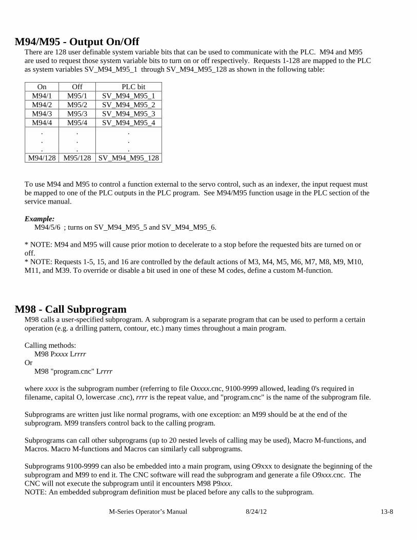
M-Series Operator’s Manual 8/24/12 13-8
M94/M95 - Output On/Off There are 128 user definable system variable bits that can be used to communicate with the PLC. M94 and M95 are used to request those system variable bits to turn on or off respectively. Requests 1-128 are mapped to the PLC as system variables SV_M94_M95_1 through SV_M94_M95_128 as shown in the following table:
On Off PLC bit M94/1 M95/1 SV_M94_M95_1 M94/2 M95/2 SV_M94_M95_2 M94/3 M95/3 SV_M94_M95_3 M94/4 M95/4 SV_M94_M95_4
. . .
. . .
. . . M94/128 M95/128 SV_M94_M95_128
To use M94 and M95 to control a function external to the servo control, such as an indexer, the input request must be mapped to one of the PLC outputs in the PLC program. See M94/M95 function usage in the PLC section of the service manual. Example:
M94/5/6 ; turns on SV_M94_M95_5 and SV_M94_M95_6. * NOTE: M94 and M95 will cause prior motion to decelerate to a stop before the requested bits are turned on or off. * NOTE: Requests 1-5, 15, and 16 are controlled by the default actions of M3, M4, M5, M6, M7, M8, M9, M10, M11, and M39. To override or disable a bit used in one of these M codes, define a custom M-function.
M98 - Call Subprogram M98 calls a user-specified subprogram. A subprogram is a separate program that can be used to perform a certain operation (e.g. a drilling pattern, contour, etc.) many times throughout a main program. Calling methods:
M98 Pxxxx Lrrrr Or
M98 "program.cnc" Lrrrr where xxxx is the subprogram number (referring to file Oxxxx.cnc, 9100-9999 allowed, leading 0's required in filename, capital O, lowercase .cnc), rrrr is the repeat value, and "program.cnc" is the name of the subprogram file. Subprograms are written just like normal programs, with one exception: an M99 should be at the end of the subprogram. M99 transfers control back to the calling program. Subprograms can call other subprograms (up to 20 nested levels of calling may be used), Macro M-functions, and Macros. Macro M-functions and Macros can similarly call subprograms. Subprograms 9100-9999 can also be embedded into a main program, using O9xxx to designate the beginning of the subprogram and M99 to end it. The CNC software will read the subprogram and generate a file O9xxx.cnc. The CNC will not execute the subprogram until it encounters M98 P9xxx. NOTE: An embedded subprogram definition must be placed before any calls to the subprogram.
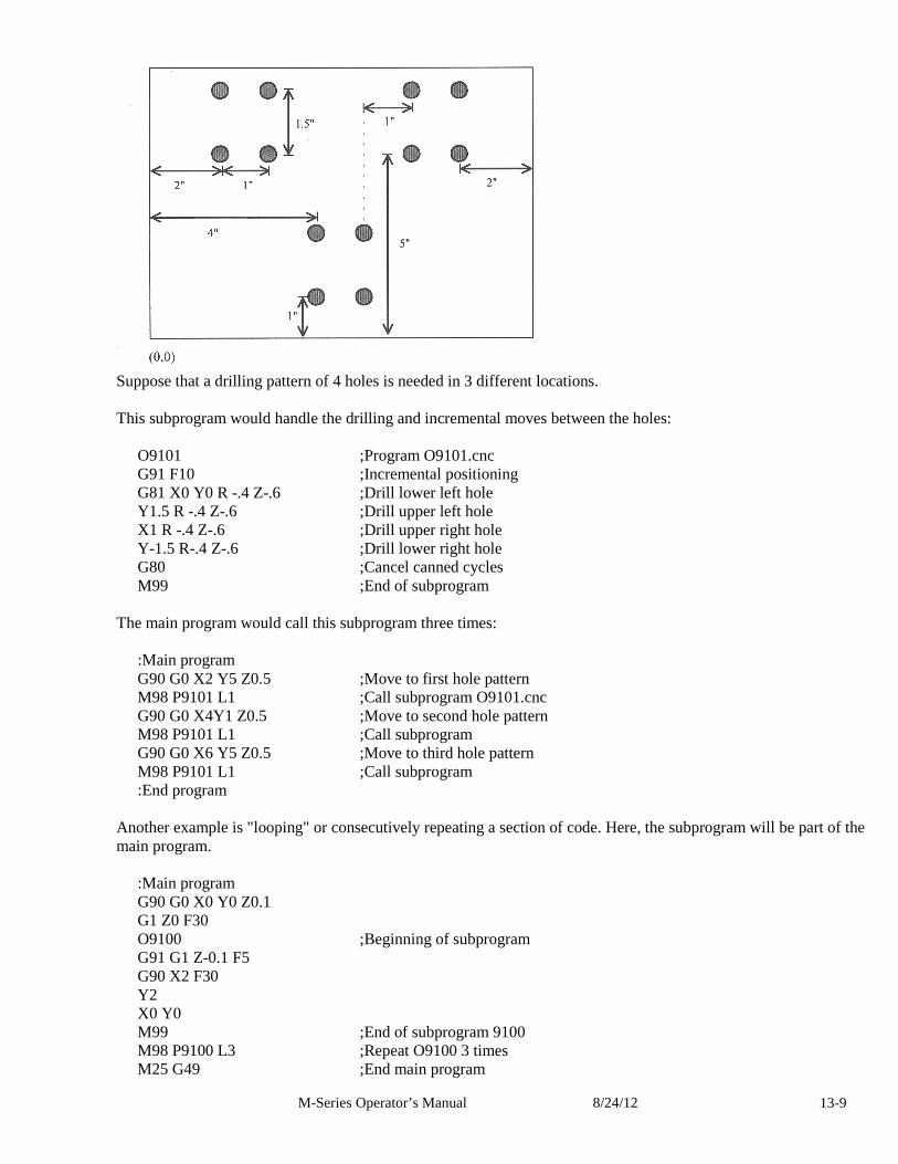
M-Series Operator’s Manual 8/24/12 13-9
Suppose that a drilling pattern of 4 holes is needed in 3 different locations. This subprogram would handle the drilling and incremental moves between the holes:
O9101 ;Program O9101.cnc G91 F10 ;Incremental positioning G81 X0 Y0 R -.4 Z-.6 ;Drill lower left hole Y1.5 R -.4 Z-.6 ;Drill upper left hole X1 R -.4 Z-.6 ;Drill upper right hole Y-1.5 R-.4 Z-.6 ;Drill lower right hole G80 ;Cancel canned cycles M99 ;End of subprogram
The main program would call this subprogram three times:
:Main program G90 G0 X2 Y5 Z0.5 ;Move to first hole pattern M98 P9101 L1 ;Call subprogram O9101.cnc G90 G0 X4Y1 Z0.5 ;Move to second hole pattern M98 P9101 L1 ;Call subprogram G90 G0 X6 Y5 Z0.5 ;Move to third hole pattern M98 P9101 L1 ;Call subprogram :End program
Another example is "looping" or consecutively repeating a section of code. Here, the subprogram will be part of the main program.
:Main program G90 G0 X0 Y0 Z0.1 G1 Z0 F30 O9100 ;Beginning of subprogram G91 G1 Z-0.1 F5 G90 X2 F30 Y2 X0 Y0 M99 ;End of subprogram 9100 M98 P9100 L3 ;Repeat O9100 3 times M25 G49 ;End main program
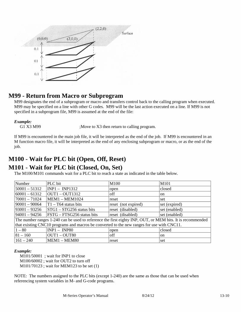
M-Series Operator’s Manual 8/24/12 13-10
M99 - Return from Macro or Subprogram M99 designates the end of a subprogram or macro and transfers control back to the calling program when executed. M99 may be specified on a line with other G codes. M99 will be the last action executed on a line. If M99 is not specified in a subprogram file, M99 is assumed at the end of the file: Example:
G1 X3 M99 ;Move to X3 then return to calling program. If M99 is encountered in the main job file, it will be interpreted as the end of the job. If M99 is encountered in an M function macro file, it will be interpreted as the end of any enclosing subprogram or macro, or as the end of the job.
M100 - Wait for PLC bit (Open, Off, Reset) M101 - Wait for PLC bit (Closed, On, Set)
The M100/M101 commands wait for a PLC bit to reach a state as indicated in the table below. Number PLC bit M100 M101 50001 – 51312 INP1 – INP1312 open closed 60001 – 61312 OUT1 – OUT1312 off on 70001 – 71024 MEM1 – MEM1024 reset set 90001 – 90064 T1 – T64 status bits reset (not expired) set (expired) 93001 – 93256 STG1 – STG256 status bits reset (disabled) set (enabled) 94001 – 94256 FSTG – FTSG256 status bits reset (disabled) set (enabled) The number ranges 1-240 can be used to reference the first eighty INP, OUT, or MEM bits. It is recommended that existing CNC10 programs and macros be converted to the new ranges for use with CNC11. 1 – 80 INP1 – INP80 open closed 81 – 160 OUT1 – OUT80 off on 161 – 240 MEM1 – MEM80 reset set
Example:
M101/50001 ; wait for INP1 to close M100/60002 ; wait for OUT2 to turn off M101/70123 ; wait for MEM123 to be set (1)
NOTE: The numbers assigned to the PLC bits (except 1-240) are the same as those that can be used when referencing system variables in M- and G-code programs.
M-Series Operator’s Manual 8/24/12 13-11
M102 - Restart Program M102 performs any movement requested, and restarts the program from the first line. The Z-axis is NOT moved to the home position, and the operator is NOT prompted to press the CYCLE START button to continue.
M103 - Programmed Action Timer M103 is used to set up the time limit for a timed operation. If the timer is canceled (usually by M104) before the specified time limit , the program will be canceled and the message "Programmed action timer expired" will be displayed. If another M103 is issued before the time limit expires, then this time limit is nullified and the new time limit will be set up as specified by the latest occurring M103. Note also that if M0 or M1 causes the program to stop momentarily and the “M0 jogging” feature is enabled, then the the timer will also be canceled without the need to issue M104. Example: Activate a device and wait for a response. If there is no response within 4.5 seconds, cancel the program.
M94/12 ; turn on input request 12 M103/4.5 ; start 4.5 second timer M100/4 ; wait for input 4 to open M104 ; input 4 opened, cancel timer
M104 - Cancel Programmed Action Timer M104 stops the timer started by the last M103 executed.
M105 - Move Minus to Switch M105 moves the requested axis in the minus direction at the current feedrate until the specified switch opens (if the given P parameter is positive), or until the scecified switch closes (if P parameter is negative). Example:
M105/X P5 F30 ; move the X axis in minus direction at 30"/min until ; the switch on INP5 opens
G92 X10 ; Sets X position to 10 M105/Z P-6 ; move the Z axis in minus direction until switch on INP6 closes
M106 - Move Plus to Switch M106 moves the requested axis in the plus direction at the current feedrate until the specified switch opens (if the given P parameter is positive), or until the scecified switch closes (if P parameter is negative). Example:
M106/Z P3 F30 ; move the Z axis in the plus direction at 30"/min, until ; the switch on INP3 opens
G92 X10 ; Sets Z position to 10 M106/X P-3 ; move the X axis in the plus direction until the switch on INP3 closes
M107 - Output Tool Number M107 sends the current tool number to the automatic tool changer, via the PLC. M107 does not set the tool changer strobe or look for an acknowledgement from the changer (see M6). Example:
M107 ; send request for tool to change M94/16 ; turn on tool changer strobe M101/5 ; wait for acknowledge on input 5 M95/16 ; turn off strobe M100/5 ; wait for acknowledge to be removed
M-Series Operator’s Manual 8/24/12 13-12
M108 - Enable Override Controls M108 re-enables the feedrate override and/or spindle speed override controls if they were disabled with M109. A parameter of “1” indicates the feedrate override; “2” indicates the spindle speed override. Example:
M109/1/2 ; disables feedrate and spindle speed overrides M108/1 ; re-enables feedrate override M108/2 ; re-enables spindle speed override
M109 - Disable Override Controls M109 disables the feedrate override and/or spindle speed override controls. It may be used before tapping with G85 to assure that the machine runs at the programmed feedrate and spindle speed. It is not necessary to specify M109 with G74 or G84; those cycles automatically disable and re-enable the override controls. M109 cannot be used in MDI mode. Example:
M3 S500 ; start spindle in clockwise direction, at 500 rpm F27.78 ; set feedrate for 18 pitch tap M109/1/2 ; disable feedrate and spindle speed overrides G85 X0 Y0 R.1 Z-.5 ; tap a hole M108/1/2 ; re-enable overrides
M115/M116/M125/M126* – Protected Move Probing Functions The protected move probing functions provide the capability to program customized probing routines.
The structure for these commands is: Mnnn /Axis pos Pp Ff L1
Where:
nnn is either 115, 116, 125, or 126. Axis is a valid axis label, i.e., X, Y, Z, etc. pos is an optional position P is a PLC bit number, which can be negative. F* is a feedrate (in units per minute.) L1* options for the M115/M116 commands that prevents an error if the probe does not detect a
surface Q1 is an option for M115/M116 that forces the DSP probe to move a “Recovery Distance” on
retries. (See Machine Parameter 13 for “Recovery Distance”) Note: the Q1 option only applies for DSP Probes
For M115 and M116 functions, the indicated axis will move to pos (if specified) until the corresponding PLC bit p state is 1, unless p is negative, in which case movement is until the PLC bit state is 0(closed). A “p value” of 1 to 80 (or -1 to -80) specifies PLC bits INP1-INP80. Warnings are generated in the CNC software message window for "Missing P value" and "Invalid P value." If “ pos” is not specified, M115 will move the axis in the negative direction, and M116 will move the axis in the positive direction. Note if “pos” is specified, then if does not matter whether M115 or M116 is used. Regardless of whether or not pos is specified, movement is bound by the settings in the software travel limits as well the maximum probing distance (Machine Parameter 16). For M125 and M126 protected move functions, the behavior is identical to that of the M115 and M116 commands, except in regards to the PLC bit state. The M115 and M116 commands are to be used when one expects contact to be made and M125 and M126 commands are to be used when one does not expect any contact to be made.
M-Series Operator’s Manual 8/24/12 13-13
Example:
Finding the center of a vertical slot. In this example, it is assumed that there is a probe connected to INP15 and that the probe tip is positioned somewhere in the slot, such that movement along the X-axis will cause a probe trigger.
M115/X P-15 F20 ; Move X minus at 20 ipm until probe trip M116/X P15 F5 ; Move X plus at 5 ipm until probe clears #100 = #5041 ; Record the point in user variable #100 M116/X P-15 F20 ; Move X plus at 20 ipm until probe trip M115/X P15 F5 ; Move X minus at 5 ipm until probe clears X[[#100+#5041]/2] ; Move X to center of slot
*Usage is slightly different when using a DSP type probe. Please see below for dissimilarities between a standard DP4 probe and the DSP type probe.
*M115/M116/M125/M126 - DSP Probe specific information
Before attempting to use the protected move probing functions with a DSP type probe, please be sure to familiarize yourself with the DSP probe configuration in Chapter 9 of this manual. Using the protected probing moves with a DSP type probe may yield unexpected results if you do not fully understand the concepts and guidelines discussed in the DSP probe configuration section.
If the control is configured to use a DSP type probe, all M115/M116 moves will perform window checking and repeat on a failed window. On a failed window, a repeat attempt is made by returning to the starting point of the move.
Protected move probing functions follow the same command format as that of a standard probe (Mnnn /Axis pos Pp Ff L1) with the following exceptions:
f This will be ignored if “Force DSP Feedrate in M115/M116” has been set to yes.
L1 Still prevents a fault from occurring. Stores last DSP position on failed window. L2 Like L1, prevents a fault from occurring but instead stores last mechanical pos. on failed window. Q1 On a failed window, force a pull back distance equal to the Probing Recovery Distance (Parameter 13), instead of moving back to the starting point. DSP position vs. mechanical position: Protected probing moves that are performed using a standard DP4 probe can collect only the point at which motion has stopped after detecting contact. This position is referred to as the “mechanical position”. When using the DSP type probe, it detects and stores the contact position “on the fly”. This position is in machine position (not a local WCS position) and is referred to as the DSP position.
Example from above – Modified to use a DSP type probe:
Finding the center of a vertical slot. M115/X P-15 ; Move X minus at DSP rate until probe trip (no feedrate needed) #100 =[[#24301]-[#2500]] ; Convert point to current WCS position, Store point in variable #100 M116/X P15 ; Move X minus at 5 ipm until probe clears M116/X P-15 ; Move X plus at DSP rate until probe trip X[[#100+[[#24301]-[#2500]]]/2] ; Move X to center of slot
Retrieving the DSP position: The last stored DSP position for axes 1-5 can be retrieved from system variables #24301-#24305 unless the L2 switch was used in which case #24301-#24305 will contain the mechanical position after a failed window.
M-Series Operator’s Manual 8/24/12 13-14
M120 - Open data file (overwrite existing file) This M function will open the requested data file for writing. If no drive or directory is specified with the file name, then the file will be opened in the same directory as the CNC program. If the file cannot be successfully opened, then an error will be returned, ultimately terminating the job. If a data file is already open when M120 is called, that file will first be closed, then the new file opened. Example:
M120 "probetst.dat" ; Opens probetst.dat file to write data too
Note: M120 and M121 also allow use of the string user variables #300 - #399 to specify a filename. As an example, given that #300 = “myfile” and #301 = “cnc”
M120 “#300.#301” ;Opens the file “myfile.cnc” for data recording.
Keep in mind however that there is a quirk in the way that the M120/M121 operates that requires the '.' to be present so assigning #301 = “.cnc” and executing M120 “#300#301” does not work and generates a “Could not open file” error message.
M121 - Open data file (append to existing file) This M function will open the requested file for writing at the end of the file. If no drive or directory is specified with the file name, then the file will be opened in the same directory as the CNC program. If the file does not already exist, it will be created. This is not an error. If the file cannot be successfully opened, then an error will be returned, ultimately terminating the job. If a data file is already open when M121 is called, that file will first be closed, then the new file opened. Example:
M121 "c:\probetst.dat" ; Opens probetst.dat file to add data to it
String variables #300-#399 may also be used to specify a file name. Please see M120 above for details.
M122 - Record local position(s) and optional comment in data file This M function will write the current expected position value to the data file, in the usual format (i.e. axis label before number, 4 decimal places in inch mode, 3 decimal places in millimeter mode. Any comment that appeared on the line with M122 will be outputted after the position(s). With no axis arguments, M122 will write the positions of all installed axes. With axis arguments, it will write the positions only of the requested axes. Positions will be written in local (not machine) coordinates, in native machine units. If no data file has been opened with M120 or M121 before M122 is called, then M122 will return an error and terminate the job. The parameter L1 may be used to suppress the new line character normally outputted after the last position. Furthermore, the output of axis labels, comma separators, and spaces can be enabled or suppressed via machine parameter 72 (see Parameter 72 in Chapter 14). If the control has been configured to use a DSP probe type, using parameter Q1 will write the values stored in #24301-#24305 to the file. Examples (M function and sample output):
M122 ;comment -> X1.2345 Y-3.2109 Z-0.5678 ;comment M122 /X L1 -> X-1.5000 M122 /X -> X-1.5000 X-2.0000
M-Series Operator’s Manual 8/24/12 13-15
M123 - Record value and/or comment in data file This M function will write the specified parameter value (if any) to the data file, followed by any comment that appeared on the line with M123. If a P value is specified, M123 will record the numeric value (4 decimal places in inches, 3 in millimeters). If neither a P value nor a comment was specified, M123 does nothing. This is not an error. If no data file has been opened with M120 or M121 before M123 is called, then M123 will return an error and terminate the job. The parameter L1 may be used to suppress the new line character normally outputted after the last value. The R and Q parameters can be used to specify the field width and precision, respectively. Furthermore, the output of axis labels, comma separators, and spaces can be enabled or suppressed via machine parameter 72 (see Parameter 72 in Chapter 14). Examples (M function and sample output):
M123 ;1.2345 ->1.2345 M123 P#A ; first macro argument ->1.2345 first macro argument M123 Q0 P1.23 ->1
M124 - Record machine position(s) and optional comment in data file Identical to M122 above except that the m124 reports machine position instead of a local WCS position.
M127 - Record Date and Time in a data file This M function is used to write the date, time, and year to the specified data file called out by the M120 or M121. Examples (M function and sample output):
M121 “testdata.dat” M127 If you opened testdata.dat you would see: Day of week, Month, day, time, and year. (i.e. Wed Aug 29 11:56:57 2007)
M128 – Move Axis by Encoder Counts M128 moves the requested axis by L which specifies an encoder count position or quantity. The L parameter is subject to the current G90/G91 mode (absolute/incremental). Example:
G91 M128/X L-5000 ; move the X axis incrementally by -5000 counts
Formatted String Commands- M200, M223, M224 & M225
The formatted string commands are provided to assist in custom screen and file I/O. A “formatted-string” is similar to the C programming language “printf” command, with various restrictions. The basic form of a formatted-string is a quoted string (comprised of a single line of up to 1024 characters) followed by a (possibly empty) list of user and/or system variable expressions. The variable expression is a '#' character followed by a number or bracketed expression. For example, given #100 = 88* (ASCII 'X'), #300 = “absolute”, and #101 = 1.2345, this string:
“The %c* axis %s position is %f” #100 #300 #101 evaluates to “The X* axis absolute position is 1.23450”
The “%c”* is replaced by the ASCII character value of user variable #100, the “%s” is replaced by the string user variable #300, and the “%f” is replaced by the value of user variable #101.
M-Series Operator’s Manual 8/24/12 13-16
Type specifiers
The 's', 'c', and 'f' are type specifiers, with 's' specifying a string user variable, 'f' specifying a floating point user variable, and 'c' specifying a single character substitution using the integer part of a floating point user variable. There should be one user variable expression for every '%' character in the quoted string. It is also possible to specify a field width by inserting a number between the '%' and the type specifier. Example:
%20s – specifies that the substituted string is displayed in a field 20 characters long, right justified and padded with spaces on the left. Use “%-20s” for left justification.
The 'f' type can specify a precision such as:
• “%.4f” - display number rounded at the fourth decimal place.
• “%9.4f” - as above but in a field width nine characters wide.
• “%+9.4f” - as above with an '+' output if variable is positive.
• “%.0f” - display number rounded to integer
If no precision is specified, “%f” will use a default precision of the current DRO display precision.
Special characters
The quoted string may contain one or more “\n”, each of which will be converted to a single newline character. Up to seven newlines can be specified in a single formatted string. However, a formatted string may not contain an embedded quote character '”' or other printf-style escape sequences such as '\t', '\\', or '\”'. If a quote character is desired, use a %c type specifier with a variable expression equal to 34.
User string variables #300-#399. These variables can be assigned a quoted string up to 80 characters in length and are retained until the CNC software is exited. For example,
#300 = “This is a text string of characters”
*The above method of representing an axis label should be used only when writing to an external file or for display in a message box. It is not valid if you are attempting to “build” a motion command in real-time from within the currently running g code program. If your intent is to use a variable to represent an axis label for a real-time command, you should instead use $ as the placeholder. The parser will replace a '$' character and the numerical expression following it with the ASCII character equivalent to the numerical expression, provided that it evaluates to the characters 'A' (65) through 'Z' (90). If the numerical expression is out-of-bounds, an “Invalid character” error occurs. Ex:
Given #100 = 88, #101 = 1, #102 = 89, #103 = 2 and #104 = 10
G1 $[#100][#101] $[#102][#103] F[#104] evaluates to G1 X1 Y2 F10
M-Series Operator’s Manual 8/24/12 13-17
M200/M201 – Stop for Operator, Prompt for Action
M200 is used to pause the currently running job and prompt the operator for action. If M0_jogging is unlocked, or the control is in DEMO mode, jogging is enabled while waiting for the operator to respond. If this option has not been enabled, the behavior will default to that of a standard M0. (jogging disabled)
The syntax is: M200 formatted-string [[user_var_expr] ...] Example:
M200 “Please jog the %c and %c axes to the desired X0, Y0 position\nPress Cycle Start to continue” #100 #101
M201 behaves exactly like M200 except that PLC bits SV_PROGRAM_RUNNING, SV_MDI_MODE, and SV_JOB_IN_PROGRESS are turned off while the prompt is displayed.
M223 – Write Formatted String to File
The M223 command writes a formatted-string to a file that was opened using the M120 or M121 commands. The syntax is:
M223 formatted-string [[user_var_expr] ...] Example:
M223 “; The measured diameter of the pocket = %.4f\n” #100
M224 – Prompt for Operator Input Using Formatted String
The M224 command displays a formatted-string and then accepts user input. The syntax is:
M224 lvalue_expr formatted-string [[user_var_expr] ...]
Where lvalue_expr is a user_var_expr that evaluates to a user variable that can be written. If lvalue_expr is a string type (#300-#399) then the user input is assigned verbatim to the string. Otherwise, the user input is evaluated as any other “bracketed” numerical expression. Example:
M224 #300 “Please enter the direction that you wish to probe in the %c axis: (+ or -)” #100
M225 – Display Formatted String for A Period of Time
The M225 command displays a formatted-string for a specified period of time. The syntax is:
M225 time_expr formatted-string [user_var] ... where time_expr is a user_var_expr that evaluates to a floating point variable specifying the number of seconds to display the output, with a value of zero interpreted as indefinitely. The CYCLE_START key can be used to immediately continue running without waiting for the time to expire. Example:
M225 #100 “Warning, %s is not selected\nPlease select %s and press Cycle Start to continue” #300 #300
M-Series Operator’s Manual 8/24/12 13-18
M300 – Fast Synchronous I/O update There are 32 user definable fast system integer variables that can be used to communicate with the PLC (similar to M94 and M95), but without causing motion to decelerate to a stop* (unlike M94 and M95). The syntax is: M300 /nn /vvv where nn is 1-32 and vvv is a 32-bit signed integer value. The parameter nn (1-32) maps to system variables SV_FSIO1 - SV_FSIO32. These commands work in conjunction with a PLC program that can read the SV_FSIOx and act upon them. Example:
M300 /21 /-1234 ; set SV_FSIO21 to integer value -1234 * NOTE: Motion will be decelerated to a stop if Smoothing is turned on (P220 = 1).
M1000-M1015 – Graphing Color for Feedrate movement
When a CNC program is graphed (F8 from the Main Screen), feedrate movements are normally plotted using the color yellow. This color setting can be changed to another color as stated in the chart below.
M Code Feedrate Graphing Color M1000 black M1001 Navy blue M1002 green M1003 teal M1004 orange M1005 blue M1006 lime M1007 aqua M1008 maroon M1009 purple M1010 olive M1011 gray M1012 red M1013 fuschia M1014 yellow M1015 white
Changing this feedrate graphing color can be used as a method highlighting or hiding parts of a graphed CNC program, but will not affect the normal run of the program (when the CYCLE START button is pressed on the Main Screen). The limitations to using these M codes are as follows: These M codes cannot be placed on the same line as another M code, and also the rapid (G0) movement color cannot be changed.
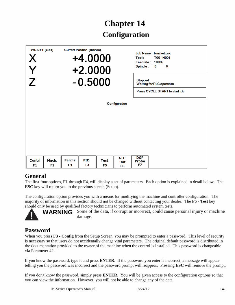
M-Series Operator’s Manual 8/24/12 14-1
Chapter 14 Configuration
General The first four options, F1 through F4, will display a set of parameters. Each option is explained in detail below. The ESC key will return you to the previous screen (Setup). The configuration option provides you with a means for modifying the machine and controller configuration. The majority of information in this section should not be changed without contacting your dealer. The F5 - Test key should only be used by qualified factory technicians to perform automated system tests.
WARNING Some of the data, if corrupt or incorrect, could cause personal injury or machine
damage.
Password When you press F3 - Config from the Setup Screen, you may be prompted to enter a password. This level of security is necessary so that users do not accidentally change vital parameters. The original default password is distributed in the documentation provided to the owner of the machine when the control is installed. This password is changeable via Parameter 42. If you know the password, type it and press ENTER. If the password you enter is incorrect, a message will appear telling you the password was incorrect and the password prompt will reappear. Pressing ESC will remove the prompt. If you don't know the password, simply press ENTER. You will be given access to the configuration options so that you can view the information. However, you will not be able to change any of the data.
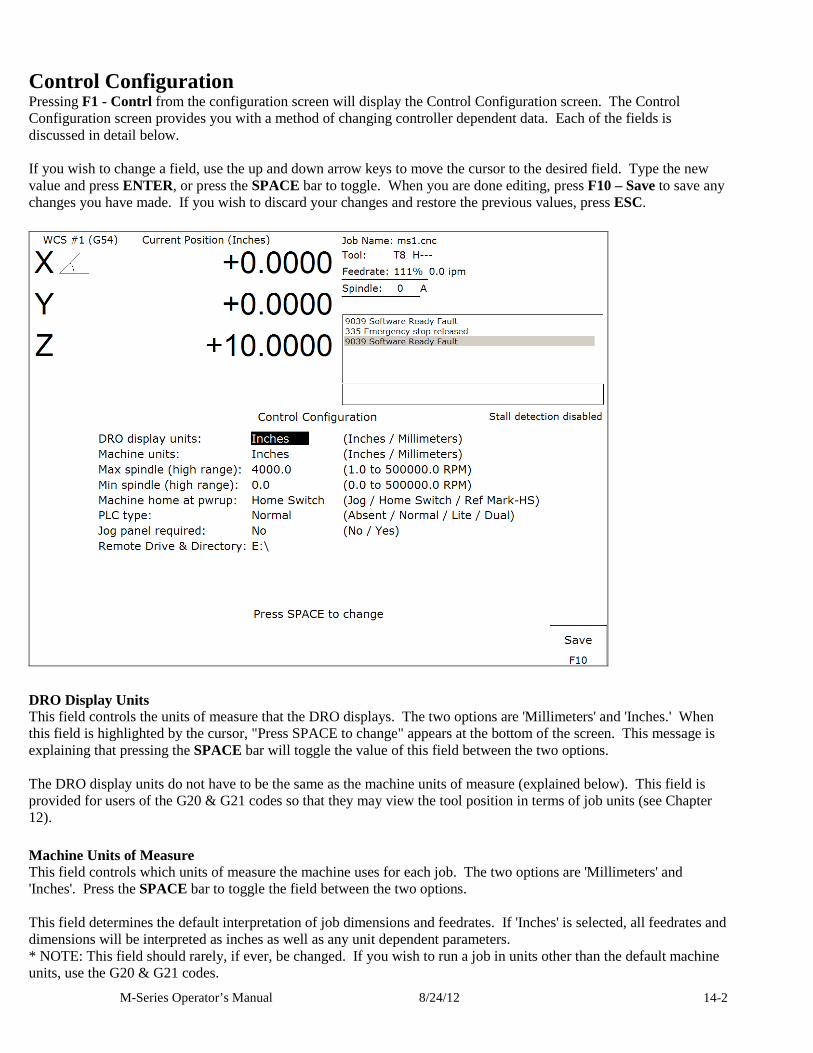
M-Series Operator’s Manual 8/24/12 14-2
Control Configuration Pressing F1 - Contrl from the configuration screen will display the Control Configuration screen. The Control Configuration screen provides you with a method of changing controller dependent data. Each of the fields is discussed in detail below. If you wish to change a field, use the up and down arrow keys to move the cursor to the desired field. Type the new value and press ENTER, or press the SPACE bar to toggle. When you are done editing, press F10 – Save to save any changes you have made. If you wish to discard your changes and restore the previous values, press ESC.
DRO Display Units This field controls the units of measure that the DRO displays. The two options are 'Millimeters' and 'Inches.' When this field is highlighted by the cursor, "Press SPACE to change" appears at the bottom of the screen. This message is explaining that pressing the SPACE bar will toggle the value of this field between the two options. The DRO display units do not have to be the same as the machine units of measure (explained below). This field is provided for users of the G20 & G21 codes so that they may view the tool position in terms of job units (see Chapter 12).
Machine Units of Measure This field controls which units of measure the machine uses for each job. The two options are 'Millimeters' and 'Inches'. Press the SPACE bar to toggle the field between the two options. This field determines the default interpretation of job dimensions and feedrates. If 'Inches' is selected, all feedrates and dimensions will be interpreted as inches as well as any unit dependent parameters. * NOTE: This field should rarely, if ever, be changed. If you wish to run a job in units other than the default machine units, use the G20 & G21 codes.
M-Series Operator’s Manual 8/24/12 14-3
Maximum Spindle Speed (High Range) This field sets the high range maximum spindle speed for those machines that have a variable frequency spindle drive controller (VFD). All spindle speeds entered in a CNC program are sent to the PLC as percentages of this maximum value. If your machine is equipped with a dual range drive and VFD, the controller will not exceed the spindle speed set by this field while in high gear. See the Machine Parameters section below for information on setting the gear ratios for medium and low gear ranges. If your machine has a VFD but is not equipped with a dual range drive, this field determines the maximum spindle speed.
Minimum Spindle Speed (High Range) This parameter is used to adjust the minimum spindle speed for the high range. This parameter allows the operator to set the minimum value for spindle speed to a value other than 0. All changes in spindle speed are made in relationship to this value, with this parameter as the minimum value. The values stored can range from 0 to 500000.0 RPM.
Machine Home at Powerup This field controls how the machine will home at powerup. Set Machine Home at Powerup to Home Switch if you have limit/home switches or safe hard stops for all axes, and wish to use the switches or stops for homing. Set Machine Home at Powerup to Ref Mark – HS if you have fixed reference marks for any axis. In Ref Mark homing, axes that contain a zero (0) for the plus or minus home switch in the Machine Configuration designate that axis to have a Ref Mark home, while non-zero values specify Limit Switch homing. Set Machine Home at Powerup to Jog if you need to manually move or jog the machine to its home position. See Chapter 1 for more information about machine home.
PLC Type This field tells the controller which PLC type is installed. This field is currently not used, and is for future expansion to different PLC types. The best setting for this field is “Normal” for now.
Jog Panel Required This field tells the controller whether a Jog Panel must be installed in order to run jobs. Also if set to “Yes” the control requires you to press cycle start twice to start a program but if it’s set to “No” programs will start with one press of CYCLE START .
Remote Drive & Directory This field sets up the remapped default drive and directory for the F3 - Remote key in the Load Job screen. This allows you to conveniently load files from an attached computer via LAN network (via RJ-45 Ethernet connection). The Control will usually remap the attached computer's C: hard drive as drive E:, depending on the way it was set up.
User Specified Paths Operators can now specify paths for INTERCON files, posted INTERCON files, Digitize files and CAD files. These paths are specified in pathm.ini. This file is automatically generated by the CNC software if it does not exist. The default pathm.ini file is:
INTERCON_PATH=c:\intercon\ ICN_POST_PATH=c:\cncm\ncfiles\ DIGITIZE_PATH=c:\cncm\ncfiles\ CAD_PATH=c:\cncm\ncfiles\
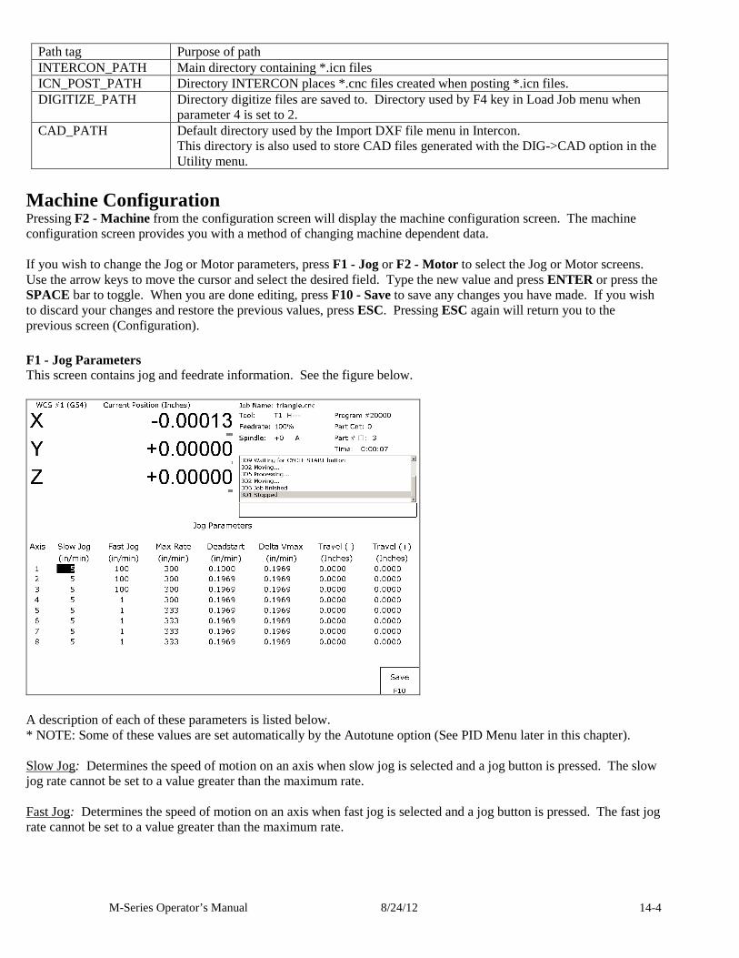
M-Series Operator’s Manual 8/24/12 14-4
Path tag Purpose of path INTERCON_PATH Main directory containing *.icn files ICN_POST_PATH Directory INTERCON places *.cnc files created when posting *.icn files. DIGITIZE_PATH Directory digitize files are saved to. Directory used by F4 key in Load Job menu when
parameter 4 is set to 2. CAD_PATH Default directory used by the Import DXF file menu in Intercon.
This directory is also used to store CAD files generated with the DIG->CAD option in the Utility menu.
Machine Configuration Pressing F2 - Machine from the configuration screen will display the machine configuration screen. The machine configuration screen provides you with a method of changing machine dependent data. If you wish to change the Jog or Motor parameters, press F1 - Jog or F2 - Motor to select the Jog or Motor screens. Use the arrow keys to move the cursor and select the desired field. Type the new value and press ENTER or press the SPACE bar to toggle. When you are done editing, press F10 - Save to save any changes you have made. If you wish to discard your changes and restore the previous values, press ESC. Pressing ESC again will return you to the previous screen (Configuration).
F1 - Jog Parameters This screen contains jog and feedrate information. See the figure below.
A description of each of these parameters is listed below. * NOTE: Some of these values are set automatically by the Autotune option (See PID Menu later in this chapter). Slow Jog: Determines the speed of motion on an axis when slow jog is selected and a jog button is pressed. The slow jog rate cannot be set to a value greater than the maximum rate. Fast Jog: Determines the speed of motion on an axis when fast jog is selected and a jog button is pressed. The fast jog rate cannot be set to a value greater than the maximum rate.
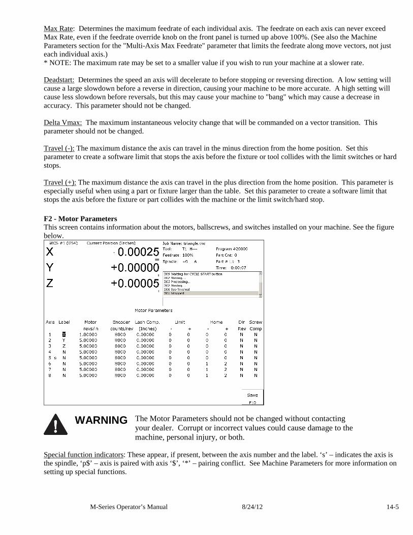
M-Series Operator’s Manual 8/24/12 14-5
Max Rate: Determines the maximum feedrate of each individual axis. The feedrate on each axis can never exceed Max Rate, even if the feedrate override knob on the front panel is turned up above 100%. (See also the Machine Parameters section for the "Multi-Axis Max Feedrate" parameter that limits the feedrate along move vectors, not just each individual axis.) * NOTE: The maximum rate may be set to a smaller value if you wish to run your machine at a slower rate. Deadstart: Determines the speed an axis will decelerate to before stopping or reversing direction. A low setting will cause a large slowdown before a reverse in direction, causing your machine to be more accurate. A high setting will cause less slowdown before reversals, but this may cause your machine to "bang" which may cause a decrease in accuracy. This parameter should not be changed. Delta Vmax: The maximum instantaneous velocity change that will be commanded on a vector transition. This parameter should not be changed. Travel (-): The maximum distance the axis can travel in the minus direction from the home position. Set this parameter to create a software limit that stops the axis before the fixture or tool collides with the limit switches or hard stops. Travel (+): The maximum distance the axis can travel in the plus direction from the home position. This parameter is especially useful when using a part or fixture larger than the table. Set this parameter to create a software limit that stops the axis before the fixture or part collides with the machine or the limit switch/hard stop.
F2 - Motor Parameters This screen contains information about the motors, ballscrews, and switches installed on your machine. See the figure below.
WARNING The Motor Parameters should not be changed without contacting
your dealer. Corrupt or incorrect values could cause damage to the machine, personal injury, or both.
Special function indicators: These appear, if present, between the axis number and the label. ‘s’ – indicates the axis is the spindle, ‘p$’ – axis is paired with axis ‘$’, ‘*’ – pairing conflict. See Machine Parameters for more information on setting up special functions.
M-Series Operator’s Manual 8/24/12 14-6
Label: The letter you want to use to identify the axis. The first three axes should normally be X, Y, and Z. If a fourth axis is installed, it is usually named W or B. If you change a label, for example from X to A, the controller will then accept G-codes for axis A instead of X. If fewer than four axes are present, the unused entries should be labeled N. If an axis is manually operated (it has an encoder but no motor), it should be labeled M. For a manual Z-axis, the 3rd axis label should be set to @ symbol. This setting allows for two axes posting in Intercon. * WARNING: Intercon does NOT post two axis programs if the 3rd axis is labeled M. * NOTE: Tool length compensation (G43-G44) and canned drilling cycles (G73-G89) always affect the third axis, regardless of its axis label. Tool diameter compensation (G41-G42) always affects the first and second axes, regardless of their axis labels. Motor revs/inch OR millimeters/motor rev: The number of revolutions of the motor that results in one inch of movement (if the machine is set up in inches). OR the number of millimeters that the machine will move as a result of one turn of the motor (if the machine is set up in millimeters). Encoder counts/rev: The counts per revolution of the encoders on your servomotors. Lash compensation: The uniform amount of backlash compensation to be applied along the whole length of the axis. Backlash can be observed during axis direction reversals and is a normal occurrence due to looseness or wear of moving parts in a machine. This parameter added to and works in conjunction with Screw Compensation (see below). Consult your machine manual or M-Series Service Manual for instructions on measuring backlash. The Lash Acceleration Coefficients, Parameters 208-215, can be used to change the speed that Lash Compensation is applied. A Coefficient of zero will effectively disable Lash Compensation. * NOTE: It is required that the machine be rehomed after changing Lash Compensation. Limits: The PLC input numbers corresponding to any limit switches that you may have on your machine. Your installer should provide this information. If no limit switch is installed, this field should be set to 0. Home: The PLC input numbers of any Home Switches you may have. These are similar to the limit switches. If your machine does not have home switches, this field should be set to the Limit Switch value. If no home or limit switch is installed, this field should be set to 0. You may then use hard stops as homing points if you choose. * NOTE: The Home Switch should never be physically located beyond the Limit Switch. Direction reversed: Used to match the +/- reference of your machine to the control electronics. Toggle this value if you actually move in the X minus direction (reverse) when you jog X+. Screw Compensation*: This value indicates whether mapping ballscrew compensation is enabled. Screw Compensation is similar to Lash Compensation (see above), but has differing compensations depending on the mapped locations along the axis. Screw Compensation is added to and works in conjunction with Lash Compensation. For more information, contact your dealer. It is recommended that you enable ballscrew error compensation at all times. * NOTE: It is recommended that a rehoming of the machine be done after changing Screw Compensation.
F3 - Find Home Press F3-Find Home to move an axis to its plus or minus home switch.
F4 - Set Home Press F4-Set Home to set Machine Home for an axis at its current position. This is usually performed after Find Home. This operation should not be used to set the part zero position. To set the part zero position, use the Part Setup screen.
F5 – M Comp This menu lets you edit the ballscrew compensation tables. NOTICE The ballscrew compensation tables should not be changed without contacting your dealer.
Corrupt or incorrect values could adversely affect the accuracy of the positioning of your machine.
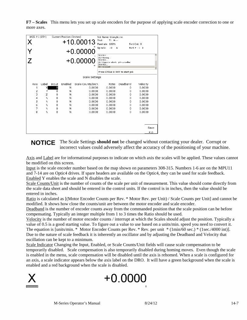
M-Series Operator’s Manual 8/24/12 14-7
F7 – Scales This menu lets you set up scale encoders for the purpose of applying scale encoder correction to one or more axes.
NOTICE The Scale Settings should not be changed without contacting your dealer. Corrupt or
incorrect values could adversely affect the accuracy of the positioning of your machine. Axis and Label are for informational purposes to indicate on which axis the scales will be applied. These values cannot be modified on this screen. Input is the scale encoder number based on the map shown on parameters 308-315. Numbers 1-6 are on the MPU11 and 7-14 are on Optic4 drives. If spare headers are available on the Optic4, they can be used for scale feedback. Enabled Y enables the scale and N disables the scale. Scale Counts/Unit is the number of counts of the scale per unit of measurement. This value should come directly from the scale data sheet and should be entered in the control units. If the control is in inches, then the value should be entered in inches. Ratio is calculated as [(Motor Encoder Counts per Rev. * Motor Rev. per Unit) / Scale Counts per Unit] and cannot be modified. It shows how close the counts/unit are between the motor encoder and scale encoder. Deadband is the number of encoder counts away from the commanded position that the scale position can be before compensating. Typically an integer multiple from 1 to 3 times the Ratio should be used. Velocity is the number of motor encoder counts / interrupt at which the Scales should adjust the position. Typically a value of 0.5 is a good starting value. To figure out a value to use based on a units/min. speed you need to convert it. The equation is [units/min. * Motor Encoder Counts per Rev. * Rev. per unit * (1min/60 sec.) * (1sec./4000 int)]. Due to the nature of scale feedback it is inherently an oscillator and by adjusting the Deadband and Velocity that oscillation can be kept to a minimum. Scale Indicator Changing the Input, Enabled, or Scale Counts/Unit fields will cause scale compensation to be temporarily disabled. Scale compensation is also temporarily disabled during homing moves. Even though the scale is enabled in the menu, scale compensation will be disabled until the axis is rehomed. When a scale is configured for an axis, a scale indicator appears below the axis label on the DRO. It will have a green background when the scale is enabled and a red background when the scale is disabled.
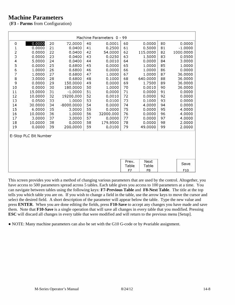
M-Series Operator’s Manual 8/24/12 14-8
Machine Parameters (F3 - Parms from Configuration)
This screen provides you with a method of changing various parameters that are used by the control. Altogether, you have access to 500 parameters spread across 5 tables. Each table gives you access to 100 parameters at a time. You can navigate between tables using the following keys: F7-Previous Table and F8-Next Table. The title at the top tells you which table you are on. If you wish to change a field in the table, use the arrow keys to move the cursor and select the desired field. A short description of the parameter will appear below the table. Type the new value and press ENTER. When you are done editing the fields, press F10-Save to accept any changes you have made and save them. Note that F10-Save is a single operation that will save all changes in every table that you modified. Pressing ESC will discard all changes in every table that were modified and will return to the previous menu [Setup]. ● NOTE: Many machine parameters can also be set with the G10 G-code or by #variable assignment.
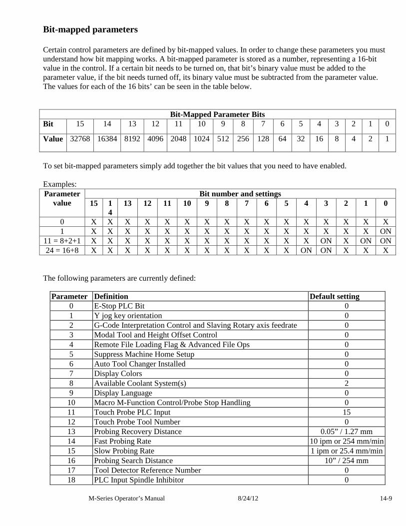
M-Series Operator’s Manual 8/24/12 14-9
Bit-mapped parameters Certain control parameters are defined by bit-mapped values. In order to change these parameters you must understand how bit mapping works. A bit-mapped parameter is stored as a number, representing a 16-bit value in the control. If a certain bit needs to be turned on, that bit’s binary value must be added to the parameter value, if the bit needs turned off, its binary value must be subtracted from the parameter value. The values for each of the 16 bits’ can be seen in the table below.
Bit-Mapped Parameter Bits Bit 15 14 13 12 11 10 9 8 7 6 5 4 3 2 1 0
Value 32768 16384 8192 4096 2048 1024 512 256 128 64 32 16 8 4 2 1
To set bit-mapped parameters simply add together the bit values that you need to have enabled. Examples:
Bit number and settings Parameter value 15 1
4 13 12 11 10 9 8 7 6 5 4 3 2 1 0
0 X X X X X X X X X X X X X X X X 1 X X X X X X X X X X X X X X X ON
11 = 8+2+1 X X X X X X X X X X X X ON X ON ON 24 = 16+8 X X X X X X X X X X X ON ON X X X
The following parameters are currently defined:
Parameter Definition Default setting 0 E-Stop PLC Bit 0 1 Y jog key orientation 0 2 G-Code Interpretation Control and Slaving Rotary axis feedrate 0 3 Modal Tool and Height Offset Control 0 4 Remote File Loading Flag & Advanced File Ops 0 5 Suppress Machine Home Setup 0 6 Auto Tool Changer Installed 0 7 Display Colors 0 8 Available Coolant System(s) 2 9 Display Language 0 10 Macro M-Function Control/Probe Stop Handling 0 11 Touch Probe PLC Input 15 12 Touch Probe Tool Number 0 13 Probing Recovery Distance 0.05” / 1.27 mm 14 Fast Probing Rate 10 ipm or 254 mm/min 15 Slow Probing Rate 1 ipm or 25.4 mm/min 16 Probing Search Distance 10” / 254 mm 17 Tool Detector Reference Number 0 18 PLC Input Spindle Inhibitor 0
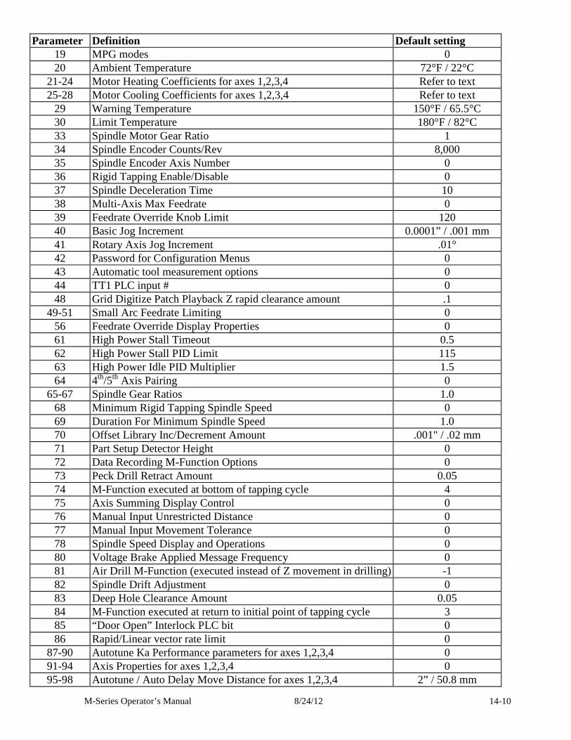
M-Series Operator’s Manual 8/24/12 14-10
Parameter Definition Default setting 19 MPG modes 0 20 Ambient Temperature 72°F / 22°C
21-24 Motor Heating Coefficients for axes 1,2,3,4 Refer to text 25-28 Motor Cooling Coefficients for axes 1,2,3,4 Refer to text
29 Warning Temperature 150°F / 65.5°C 30 Limit Temperature 180°F / 82°C 33 Spindle Motor Gear Ratio 1 34 Spindle Encoder Counts/Rev 8,000 35 Spindle Encoder Axis Number 0 36 Rigid Tapping Enable/Disable 0 37 Spindle Deceleration Time 10 38 Multi-Axis Max Feedrate 0 39 Feedrate Override Knob Limit 120 40 Basic Jog Increment 0.0001” / .001 mm 41 Rotary Axis Jog Increment .01° 42 Password for Configuration Menus 0 43 Automatic tool measurement options 0 44 TT1 PLC input # 0 48 Grid Digitize Patch Playback Z rapid clearance amount .1
49-51 Small Arc Feedrate Limiting 0 56 Feedrate Override Display Properties 0 61 High Power Stall Timeout 0.5 62 High Power Stall PID Limit 115 63 High Power Idle PID Multiplier 1.5 64 4th/5th Axis Pairing 0
65-67 Spindle Gear Ratios 1.0 68 Minimum Rigid Tapping Spindle Speed 0 69 Duration For Minimum Spindle Speed 1.0 70 Offset Library Inc/Decrement Amount .001" / .02 mm 71 Part Setup Detector Height 0 72 Data Recording M-Function Options 0 73 Peck Drill Retract Amount 0.05 74 M-Function executed at bottom of tapping cycle 4 75 Axis Summing Display Control 0 76 Manual Input Unrestricted Distance 0 77 Manual Input Movement Tolerance 0 78 Spindle Speed Display and Operations 0 80 Voltage Brake Applied Message Frequency 0 81 Air Drill M-Function (executed instead of Z movement in drilling) -1 82 Spindle Drift Adjustment 0 83 Deep Hole Clearance Amount 0.05 84 M-Function executed at return to initial point of tapping cycle 3 85 “Door Open” Interlock PLC bit 0 86 Rapid/Linear vector rate limit 0
87-90 Autotune Ka Performance parameters for axes 1,2,3,4 0 91-94 Axis Properties for axes 1,2,3,4 0 95-98 Autotune / Auto Delay Move Distance for axes 1,2,3,4 2” / 50.8 mm
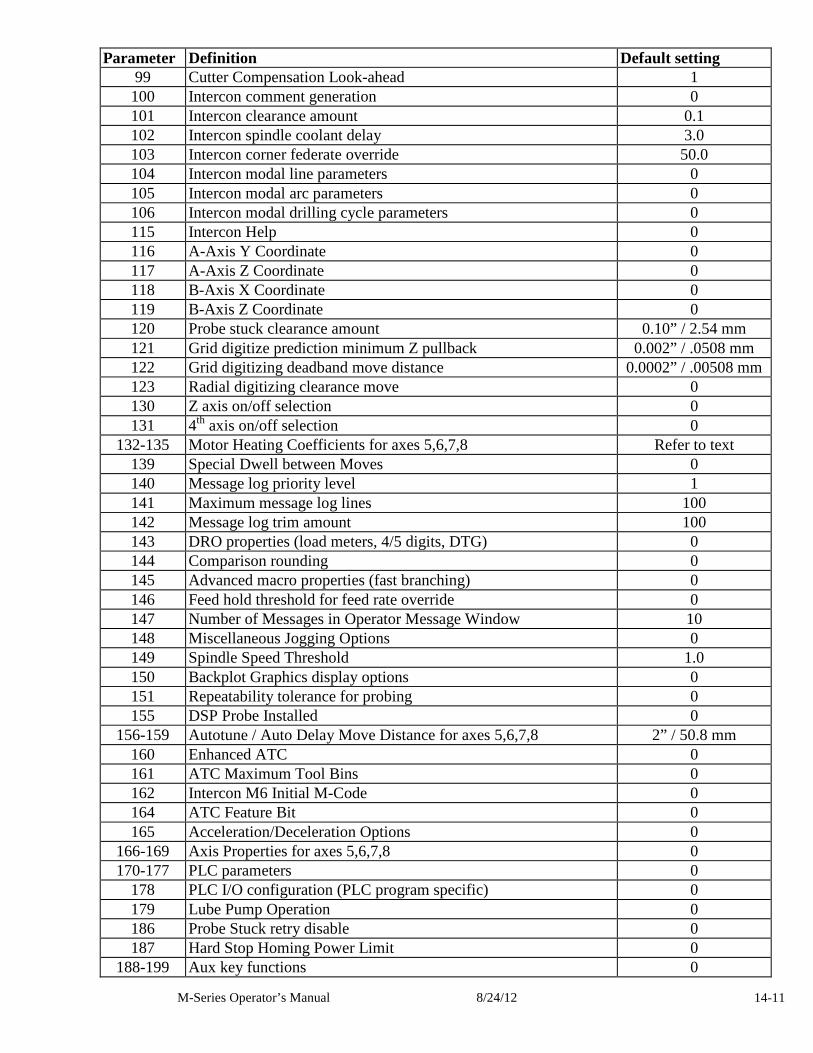
M-Series Operator’s Manual 8/24/12 14-11
Parameter Definition Default setting 99 Cutter Compensation Look-ahead 1 100 Intercon comment generation 0 101 Intercon clearance amount 0.1 102 Intercon spindle coolant delay 3.0 103 Intercon corner federate override 50.0 104 Intercon modal line parameters 0 105 Intercon modal arc parameters 0 106 Intercon modal drilling cycle parameters 0 115 Intercon Help 0 116 A-Axis Y Coordinate 0 117 A-Axis Z Coordinate 0 118 B-Axis X Coordinate 0 119 B-Axis Z Coordinate 0 120 Probe stuck clearance amount 0.10” / 2.54 mm 121 Grid digitize prediction minimum Z pullback 0.002” / .0508 mm 122 Grid digitizing deadband move distance 0.0002” / .00508 mm 123 Radial digitizing clearance move 0 130 Z axis on/off selection 0 131 4th axis on/off selection 0
132-135 Motor Heating Coefficients for axes 5,6,7,8 Refer to text 139 Special Dwell between Moves 0 140 Message log priority level 1 141 Maximum message log lines 100 142 Message log trim amount 100 143 DRO properties (load meters, 4/5 digits, DTG) 0 144 Comparison rounding 0 145 Advanced macro properties (fast branching) 0 146 Feed hold threshold for feed rate override 0 147 Number of Messages in Operator Message Window 10 148 Miscellaneous Jogging Options 0 149 Spindle Speed Threshold 1.0 150 Backplot Graphics display options 0 151 Repeatability tolerance for probing 0 155 DSP Probe Installed 0
156-159 Autotune / Auto Delay Move Distance for axes 5,6,7,8 2” / 50.8 mm 160 Enhanced ATC 0 161 ATC Maximum Tool Bins 0 162 Intercon M6 Initial M-Code 0 164 ATC Feature Bit 0 165 Acceleration/Deceleration Options 0
166-169 Axis Properties for axes 5,6,7,8 0 170-177 PLC parameters 0
178 PLC I/O configuration (PLC program specific) 0 179 Lube Pump Operation 0 186 Probe Stuck retry disable 0 187 Hard Stop Homing Power Limit 0
188-199 Aux key functions 0
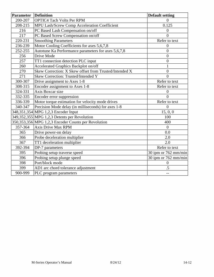
M-Series Operator’s Manual 8/24/12 14-12
Parameter Definition Default setting 200-207 OPTIC4 Tach Volts Per RPM 0 208-215 MPU Lash/Screw Comp Acceleration Coefficient 0.125
216 PC Based Lash Compensation on/off 0 217 PC Based Screw Compensation on/off 0
220-231 Smoothing Parameters Refer to text 236-239 Motor Cooling Coefficients for axes 5,6,7,8 0 252-255 Autotune Ka Performance parameters for axes 5,6,7,8 0
256 Drive Mode 0 257 TT1 connection detection PLC input 0 260 Accelerated Graphics Backplot on/off 1 270 Skew Correction: X Skew offset from Trusted/Intended X 0 271 Skew Correction: Trusted/Intended Y 0
300-307 Drive assignment to Axes 1-8 Refer to text 308-315 Encoder assignment to Axes 1-8 Refer to text 324-331 Axis Boxcar size 0 332-335 Encoder error suppression 0 336-339 Motor torque estimation for velocity mode drives Refer to text 340-347 Precision Mode delay (in milliseconds) for axes 1-8 0
348,351,354 MPG 1,2,3 Encoder Input 15, 0, 0 349,352,355 MPG 1,2,3 Detents per Revolution 100 350,353,356 MPG 1,2,3 Encoder Counts per Revolution 400
357-364 Axis Drive Max RPM 0 365 Drive power-on delay 0.0 366 Probe deceleration multiplier 2.0 367 TT1 deceleration multiplier 2.0
392-394 DP-7 parameters Refer to text 395 Probing setup traverse speed 30 ipm or 762 mm/min 396 Probing setup plunge speed 30 ipm or 762 mm/min 398 Port/block mode 0 399 AD1 arc chord tolerance adjustment .5
900-999 PLC program parameters --
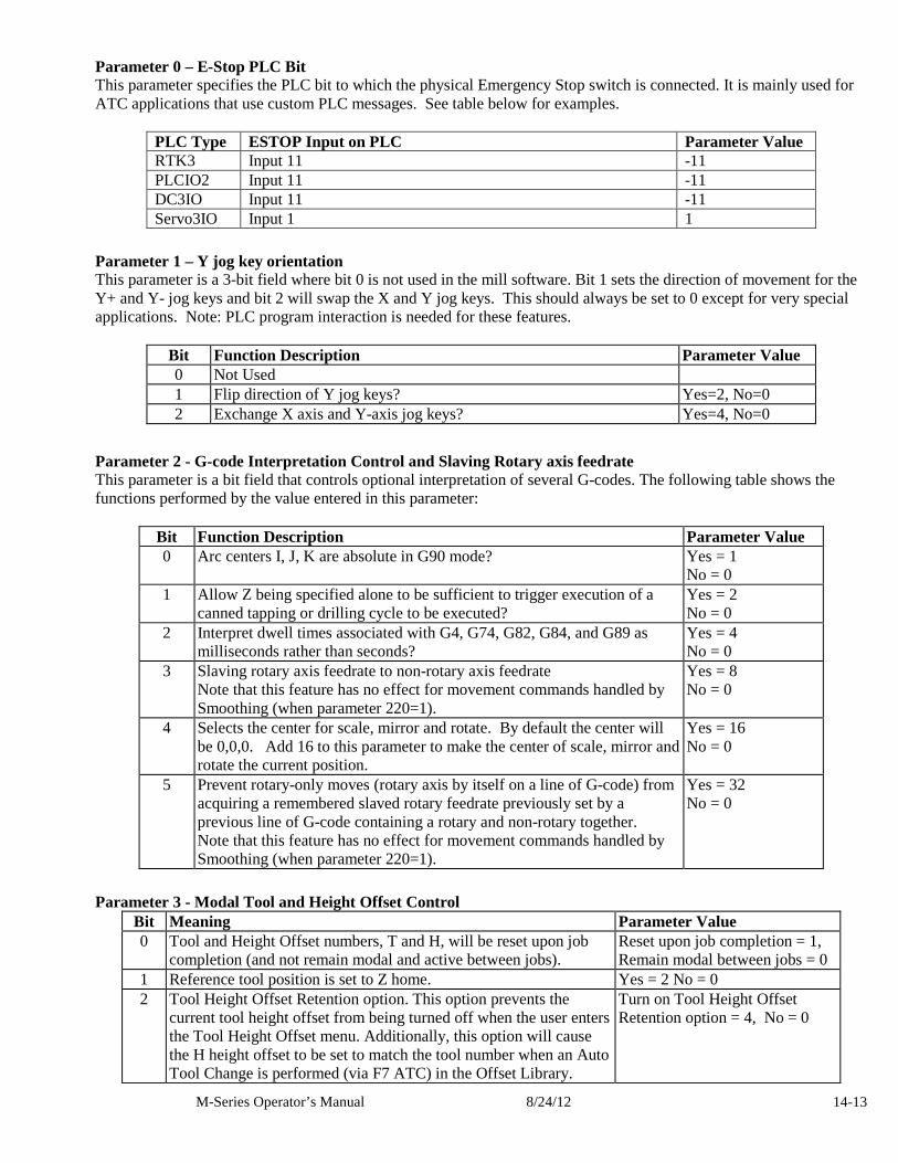
M-Series Operator’s Manual 8/24/12 14-13
Parameter 0 – E-Stop PLC Bit This parameter specifies the PLC bit to which the physical Emergency Stop switch is connected. It is mainly used for ATC applications that use custom PLC messages. See table below for examples.
PLC Type ESTOP Input on PLC Parameter Value RTK3 Input 11 -11 PLCIO2 Input 11 -11 DC3IO Input 11 -11 Servo3IO Input 1 1
Parameter 1 – Y jog key orientation This parameter is a 3-bit field where bit 0 is not used in the mill software. Bit 1 sets the direction of movement for the Y+ and Y- jog keys and bit 2 will swap the X and Y jog keys. This should always be set to 0 except for very special applications. Note: PLC program interaction is needed for these features.
Bit Function Description Parameter Value 0 Not Used 1 Flip direction of Y jog keys? Yes=2, No=0 2 Exchange X axis and Y-axis jog keys? Yes=4, No=0
Parameter 2 - G-code Interpretation Control and Slaving Rotary axis feedrate This parameter is a bit field that controls optional interpretation of several G-codes. The following table shows the functions performed by the value entered in this parameter:
Bit Function Description Parameter Value 0 Arc centers I, J, K are absolute in G90 mode? Yes = 1
No = 0 1 Allow Z being specified alone to be sufficient to trigger execution of a
canned tapping or drilling cycle to be executed? Yes = 2 No = 0
2 Interpret dwell times associated with G4, G74, G82, G84, and G89 as milliseconds rather than seconds?
Yes = 4 No = 0
3 Slaving rotary axis feedrate to non-rotary axis feedrate Note that this feature has no effect for movement commands handled by Smoothing (when parameter 220=1).
Yes = 8 No = 0
4 Selects the center for scale, mirror and rotate. By default the center will be 0,0,0. Add 16 to this parameter to make the center of scale, mirror and rotate the current position.
Yes = 16 No = 0
5 Prevent rotary-only moves (rotary axis by itself on a line of G-code) from acquiring a remembered slaved rotary feedrate previously set by a previous line of G-code containing a rotary and non-rotary together. Note that this feature has no effect for movement commands handled by Smoothing (when parameter 220=1).
Yes = 32 No = 0
Parameter 3 - Modal Tool and Height Offset Control Bit Meaning Parameter Value 0 Tool and Height Offset numbers, T and H, will be reset upon job
completion (and not remain modal and active between jobs). Reset upon job completion = 1, Remain modal between jobs = 0
1 Reference tool position is set to Z home. Yes = 2 No = 0 2 Tool Height Offset Retention option. This option prevents the
current tool height offset from being turned off when the user enters the Tool Height Offset menu. Additionally, this option will cause the H height offset to be set to match the tool number when an Auto Tool Change is performed (via F7 ATC) in the Offset Library.
Turn on Tool Height Offset Retention option = 4, No = 0
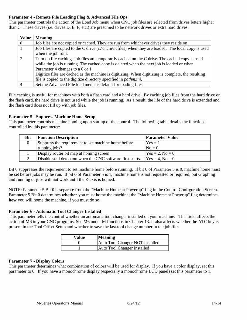
M-Series Operator’s Manual 8/24/12 14-14
Parameter 4 - Remote File Loading Flag & Advanced File Ops This parameter controls the action of the Load Job menu when CNC job files are selected from drives letters higher than C. These drives (i.e. drives D, E, F, etc.) are presumed to be network drives or extra hard drives.
Value Meaning 0 Job files are not copied or cached. They are run from whichever drives they reside on. 1 Job files are copied to the C drive (c:\cncm\ncfiles) when they are loaded. The local copy is used
when the job runs. 2 Turn on file caching. Job files are temporarily cached on the C drive. The cached copy is used
while the job is running. The cached copy is deleted when the next job is loaded or when Parameter 4 changes to a 0 or 1. Digitize files are cached as the machine is digitizing. When digitizing is complete, the resulting file is copied to the digitize directory specified in pathm.ini.
4 Set the Advanced File load menu as default for loading files File caching is useful for machines with both a flash card and a hard drive. By caching job files from the hard drive on the flash card, the hard drive is not used while the job is running. As a result, the life of the hard drive is extended and the flash card does not fill up with job files.
Parameter 5 - Suppress Machine Home Setup This parameter controls machine homing upon startup of the control. The following table details the functions controlled by this parameter:
Bit Function Description Parameter Value 0 Suppress the requirement to set machine home before
running jobs? Yes = 1 No = 0
1 Display router bit map at homing screen Yes = 2, No = 0 2 Disable stall detection when the CNC software first starts. Yes = 4, No = 0
Bit 0 suppresses the requirement to set machine home before running. If bit 0 of Parameter 5 is 0, machine home must be set before jobs may be run. If bit 0 of Parameter 5 is 1, machine home is not requested or required, but Graphing and running of jobs will not work until the Z-axis is homed. NOTE: Parameter 5 Bit 0 is separate from the "Machine Home at Powerup" flag in the Control Configuration Screen. Parameter 5 Bit 0 determines whether you must home the machine; the "Machine Home at Powerup" flag determines how you will home the machine, if you must do so.
Parameter 6 - Automatic Tool Changer Installed This parameter tells the control whether an automatic tool changer installed on your machine. This field affects the action of M6 in your CNC programs. See M6 under M functions in Chapter 13. It also affects whether the ATC key is present in the Tool Offset Setup and whether to save the last tool change number in the job files.
Value Meaning 0 Auto Tool Changer NOT Installed 1 Auto Tool Changer Installed
Parameter 7 - Display Colors This parameter determines what combination of colors will be used for display. If you have a color display, set this parameter to 0. If you have a monochrome display (especially a monochrome LCD panel) set this parameter to 1.
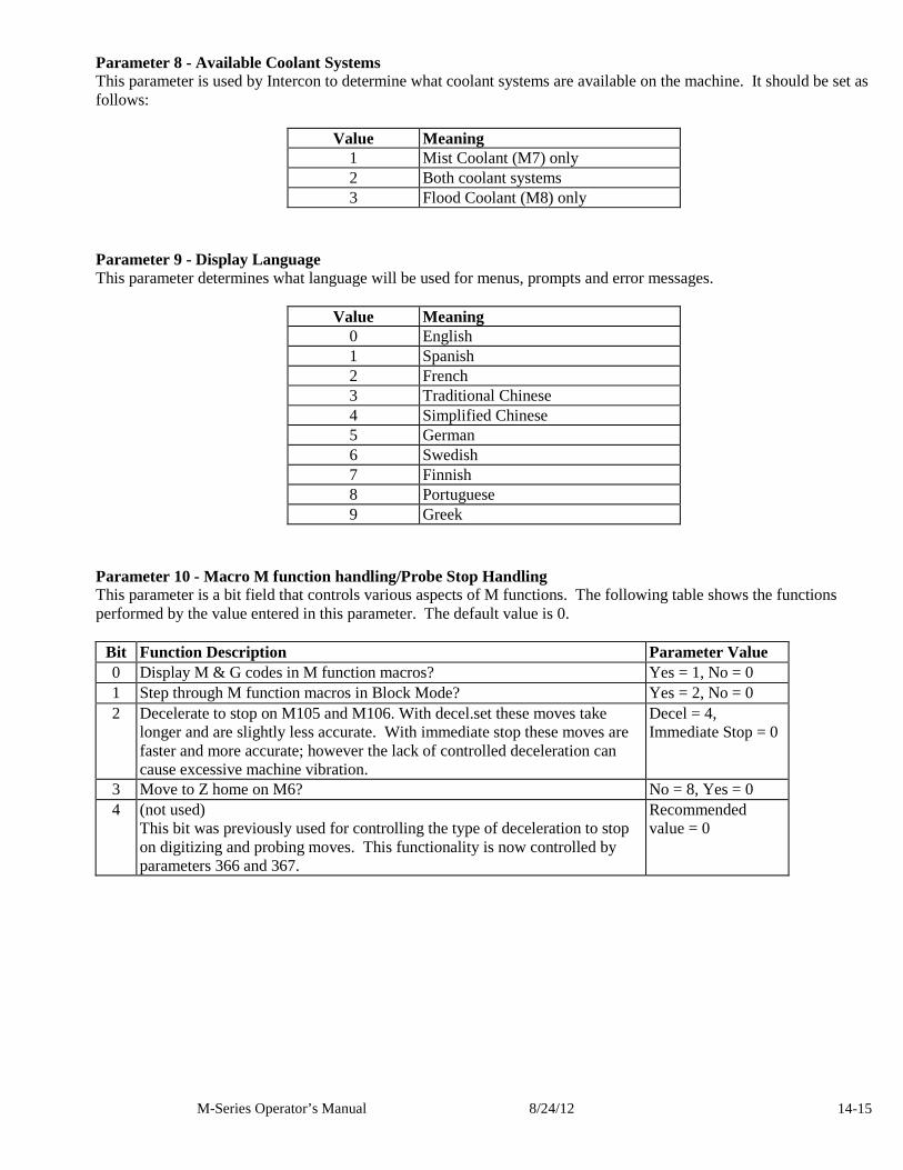
M-Series Operator’s Manual 8/24/12 14-15
Parameter 8 - Available Coolant Systems This parameter is used by Intercon to determine what coolant systems are available on the machine. It should be set as follows:
Value Meaning 1 Mist Coolant (M7) only 2 Both coolant systems 3 Flood Coolant (M8) only
Parameter 9 - Display Language This parameter determines what language will be used for menus, prompts and error messages.
Value Meaning 0 English 1 Spanish 2 French 3 Traditional Chinese 4 Simplified Chinese 5 German 6 Swedish 7 Finnish 8 Portuguese 9 Greek
Parameter 10 - Macro M function handling/Probe Stop Handling This parameter is a bit field that controls various aspects of M functions. The following table shows the functions performed by the value entered in this parameter. The default value is 0.
Bit Function Description Parameter Value 0 Display M & G codes in M function macros? Yes = 1, No = 0 1 Step through M function macros in Block Mode? Yes = 2, No = 0 2 Decelerate to stop on M105 and M106. With decel.set these moves take
longer and are slightly less accurate. With immediate stop these moves are faster and more accurate; however the lack of controlled deceleration can cause excessive machine vibration.
Decel = 4, Immediate Stop = 0
3 Move to Z home on M6? No = 8, Yes = 0 4 (not used)
This bit was previously used for controlling the type of deceleration to stop on digitizing and probing moves. This functionality is now controlled by parameters 366 and 367.
Recommended value = 0
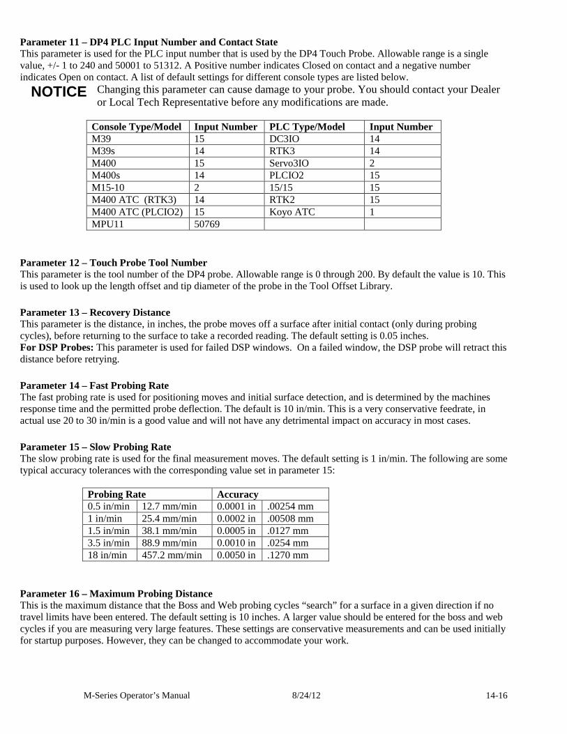
M-Series Operator’s Manual 8/24/12 14-16
Parameter 11 – DP4 PLC Input Number and Contact State This parameter is used for the PLC input number that is used by the DP4 Touch Probe. Allowable range is a single value, +/- 1 to 240 and 50001 to 51312. A Positive number indicates Closed on contact and a negative number indicates Open on contact. A list of default settings for different console types are listed below. NOTICE Changing this parameter can cause damage to your probe. You should contact your Dealer
or Local Tech Representative before any modifications are made.
Console Type/Model Input Number PLC Type/Model Input Number M39 15 DC3IO 14 M39s 14 RTK3 14 M400 15 Servo3IO 2 M400s 14 PLCIO2 15 M15-10 2 15/15 15 M400 ATC (RTK3) 14 RTK2 15 M400 ATC (PLCIO2) 15 Koyo ATC 1 MPU11 50769
Parameter 12 – Touch Probe Tool Number This parameter is the tool number of the DP4 probe. Allowable range is 0 through 200. By default the value is 10. This is used to look up the length offset and tip diameter of the probe in the Tool Offset Library.
Parameter 13 – Recovery Distance This parameter is the distance, in inches, the probe moves off a surface after initial contact (only during probing cycles), before returning to the surface to take a recorded reading. The default setting is 0.05 inches. For DSP Probes: This parameter is used for failed DSP windows. On a failed window, the DSP probe will retract this distance before retrying.
Parameter 14 – Fast Probing Rate The fast probing rate is used for positioning moves and initial surface detection, and is determined by the machines response time and the permitted probe deflection. The default is 10 in/min. This is a very conservative feedrate, in actual use 20 to 30 in/min is a good value and will not have any detrimental impact on accuracy in most cases.
Parameter 15 – Slow Probing Rate The slow probing rate is used for the final measurement moves. The default setting is 1 in/min. The following are some typical accuracy tolerances with the corresponding value set in parameter 15:
Probing Rate Accuracy 0.5 in/min 12.7 mm/min 0.0001 in .00254 mm 1 in/min 25.4 mm/min 0.0002 in .00508 mm 1.5 in/min 38.1 mm/min 0.0005 in .0127 mm 3.5 in/min 88.9 mm/min 0.0010 in .0254 mm 18 in/min 457.2 mm/min 0.0050 in .1270 mm
Parameter 16 – Maximum Probing Distance This is the maximum distance that the Boss and Web probing cycles “search” for a surface in a given direction if no travel limits have been entered. The default setting is 10 inches. A larger value should be entered for the boss and web cycles if you are measuring very large features. These settings are conservative measurements and can be used initially for startup purposes. However, they can be changed to accommodate your work.
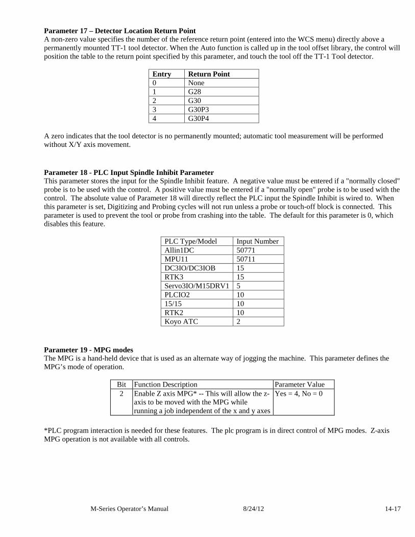
M-Series Operator’s Manual 8/24/12 14-17
Parameter 17 – Detector Location Return Point A non-zero value specifies the number of the reference return point (entered into the WCS menu) directly above a permanently mounted TT-1 tool detector. When the Auto function is called up in the tool offset library, the control will position the table to the return point specified by this parameter, and touch the tool off the TT-1 Tool detector.
Entry Return Point 0 None 1 G28 2 G30 3 G30P3 4 G30P4
A zero indicates that the tool detector is no permanently mounted; automatic tool measurement will be performed without X/Y axis movement.
Parameter 18 - PLC Input Spindle Inhibit Parameter This parameter stores the input for the Spindle Inhibit feature. A negative value must be entered if a "normally closed" probe is to be used with the control. A positive value must be entered if a "normally open" probe is to be used with the control. The absolute value of Parameter 18 will directly reflect the PLC input the Spindle Inhibit is wired to. When this parameter is set, Digitizing and Probing cycles will not run unless a probe or touch-off block is connected. This parameter is used to prevent the tool or probe from crashing into the table. The default for this parameter is 0, which disables this feature.
PLC Type/Model Input Number Allin1DC 50771 MPU11 50711 DC3IO/DC3IOB 15 RTK3 15 Servo3IO/M15DRV1 5 PLCIO2 10 15/15 10 RTK2 10 Koyo ATC 2
Parameter 19 - MPG modes The MPG is a hand-held device that is used as an alternate way of jogging the machine. This parameter defines the MPG’s mode of operation.
Bit Function Description Parameter Value 2 Enable Z axis MPG* -- This will allow the z-
axis to be moved with the MPG while running a job independent of the x and y axes
Yes = 4, No = 0
*PLC program interaction is needed for these features. The plc program is in direct control of MPG modes. Z-axis MPG operation is not available with all controls.
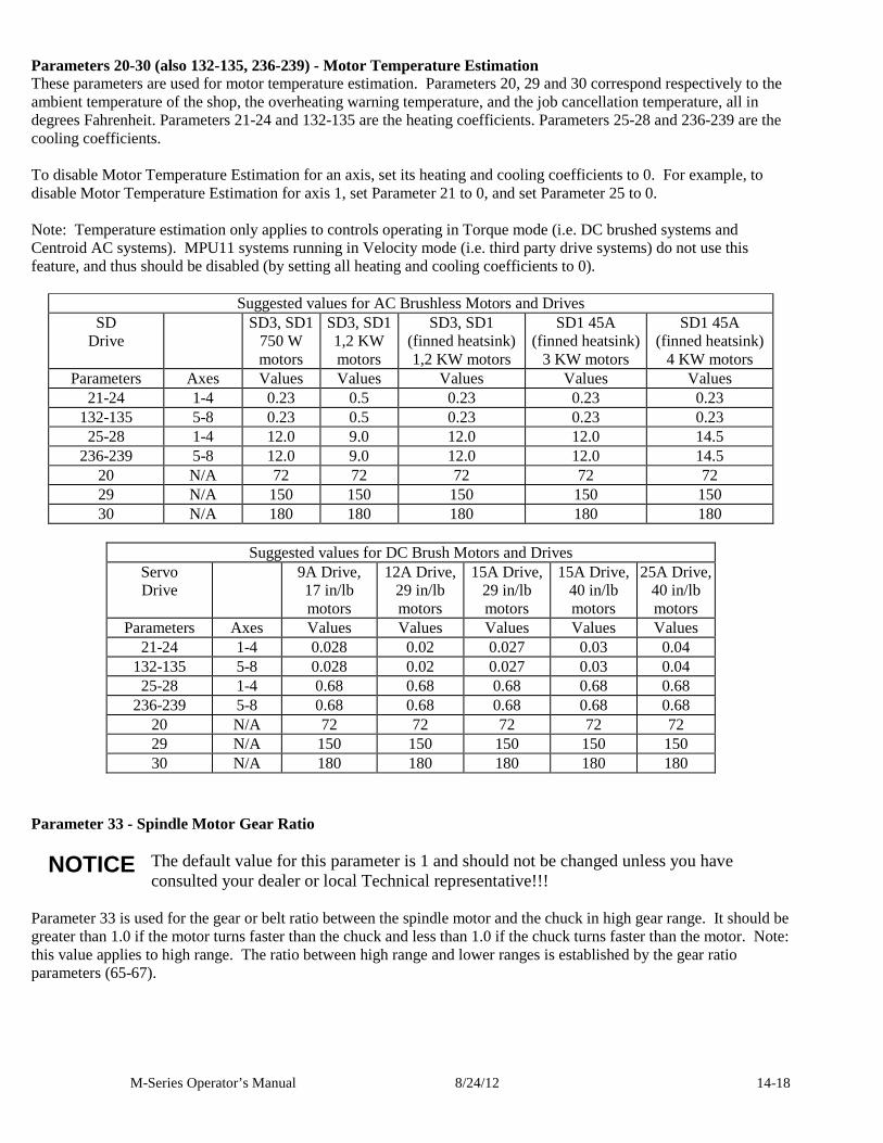
M-Series Operator’s Manual 8/24/12 14-18
Parameters 20-30 (also 132-135, 236-239) - Motor Temperature Estimation These parameters are used for motor temperature estimation. Parameters 20, 29 and 30 correspond respectively to the ambient temperature of the shop, the overheating warning temperature, and the job cancellation temperature, all in degrees Fahrenheit. Parameters 21-24 and 132-135 are the heating coefficients. Parameters 25-28 and 236-239 are the cooling coefficients. To disable Motor Temperature Estimation for an axis, set its heating and cooling coefficients to 0. For example, to disable Motor Temperature Estimation for axis 1, set Parameter 21 to 0, and set Parameter 25 to 0. Note: Temperature estimation only applies to controls operating in Torque mode (i.e. DC brushed systems and Centroid AC systems). MPU11 systems running in Velocity mode (i.e. third party drive systems) do not use this feature, and thus should be disabled (by setting all heating and cooling coefficients to 0).
Suggested values for AC Brushless Motors and Drives SD
Drive SD3, SD1
750 W motors
SD3, SD1 1,2 KW motors
SD3, SD1 (finned heatsink) 1,2 KW motors
SD1 45A (finned heatsink)
3 KW motors
SD1 45A (finned heatsink)
4 KW motors Parameters Axes Values Values Values Values Values
21-24 1-4 0.23 0.5 0.23 0.23 0.23 132-135 5-8 0.23 0.5 0.23 0.23 0.23 25-28 1-4 12.0 9.0 12.0 12.0 14.5
236-239 5-8 12.0 9.0 12.0 12.0 14.5 20 N/A 72 72 72 72 72 29 N/A 150 150 150 150 150 30 N/A 180 180 180 180 180
Suggested values for DC Brush Motors and Drives
Servo Drive
9A Drive, 17 in/lb motors
12A Drive, 29 in/lb motors
15A Drive, 29 in/lb motors
15A Drive, 40 in/lb motors
25A Drive, 40 in/lb motors
Parameters Axes Values Values Values Values Values 21-24 1-4 0.028 0.02 0.027 0.03 0.04
132-135 5-8 0.028 0.02 0.027 0.03 0.04 25-28 1-4 0.68 0.68 0.68 0.68 0.68
236-239 5-8 0.68 0.68 0.68 0.68 0.68 20 N/A 72 72 72 72 72 29 N/A 150 150 150 150 150 30 N/A 180 180 180 180 180
Parameter 33 - Spindle Motor Gear Ratio NOTICE The default value for this parameter is 1 and should not be changed unless you have
consulted your dealer or local Technical representative!!! Parameter 33 is used for the gear or belt ratio between the spindle motor and the chuck in high gear range. It should be greater than 1.0 if the motor turns faster than the chuck and less than 1.0 if the chuck turns faster than the motor. Note: this value applies to high range. The ratio between high range and lower ranges is established by the gear ratio parameters (65-67).
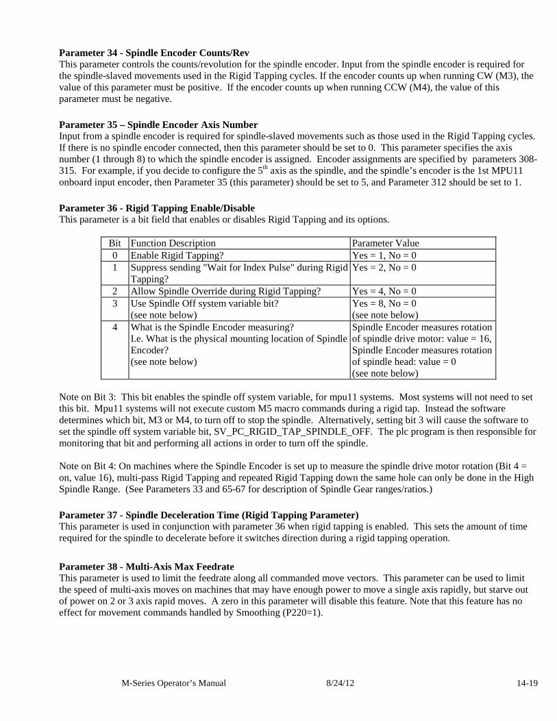
M-Series Operator’s Manual 8/24/12 14-19
Parameter 34 - Spindle Encoder Counts/Rev This parameter controls the counts/revolution for the spindle encoder. Input from the spindle encoder is required for the spindle-slaved movements used in the Rigid Tapping cycles. If the encoder counts up when running CW (M3), the value of this parameter must be positive. If the encoder counts up when running CCW (M4), the value of this parameter must be negative.
Parameter 35 – Spindle Encoder Axis Number Input from a spindle encoder is required for spindle-slaved movements such as those used in the Rigid Tapping cycles. If there is no spindle encoder connected, then this parameter should be set to 0. This parameter specifies the axis number (1 through 8) to which the spindle encoder is assigned. Encoder assignments are specified by parameters 308-315. For example, if you decide to configure the 5th axis as the spindle, and the spindle’s encoder is the 1st MPU11 onboard input encoder, then Parameter 35 (this parameter) should be set to 5, and Parameter 312 should be set to 1.
Parameter 36 - Rigid Tapping Enable/Disable This parameter is a bit field that enables or disables Rigid Tapping and its options.
Bit Function Description Parameter Value 0 Enable Rigid Tapping? Yes = 1, No = 0 1 Suppress sending "Wait for Index Pulse" during Rigid
Tapping? Yes = 2, No = 0
2 Allow Spindle Override during Rigid Tapping? Yes = 4, No = 0 3 Use Spindle Off system variable bit?
(see note below) Yes = 8, No = 0 (see note below)
4 What is the Spindle Encoder measuring? I.e. What is the physical mounting location of Spindle Encoder? (see note below)
Spindle Encoder measures rotation of spindle drive motor: value = 16, Spindle Encoder measures rotation of spindle head: value = 0 (see note below)
Note on Bit 3: This bit enables the spindle off system variable, for mpu11 systems. Most systems will not need to set this bit. Mpu11 systems will not execute custom M5 macro commands during a rigid tap. Instead the software determines which bit, M3 or M4, to turn off to stop the spindle. Alternatively, setting bit 3 will cause the software to set the spindle off system variable bit, SV_PC_RIGID_TAP_SPINDLE_OFF. The plc program is then responsible for monitoring that bit and performing all actions in order to turn off the spindle. Note on Bit 4: On machines where the Spindle Encoder is set up to measure the spindle drive motor rotation (Bit 4 = on, value 16), multi-pass Rigid Tapping and repeated Rigid Tapping down the same hole can only be done in the High Spindle Range. (See Parameters 33 and 65-67 for description of Spindle Gear ranges/ratios.)
Parameter 37 - Spindle Deceleration Time (Rigid Tapping Parameter) This parameter is used in conjunction with parameter 36 when rigid tapping is enabled. This sets the amount of time required for the spindle to decelerate before it switches direction during a rigid tapping operation.
Parameter 38 - Multi-Axis Max Feedrate This parameter is used to limit the feedrate along all commanded move vectors. This parameter can be used to limit the speed of multi-axis moves on machines that may have enough power to move a single axis rapidly, but starve out of power on 2 or 3 axis rapid moves. A zero in this parameter will disable this feature. Note that this feature has no effect for movement commands handled by Smoothing (P220=1).
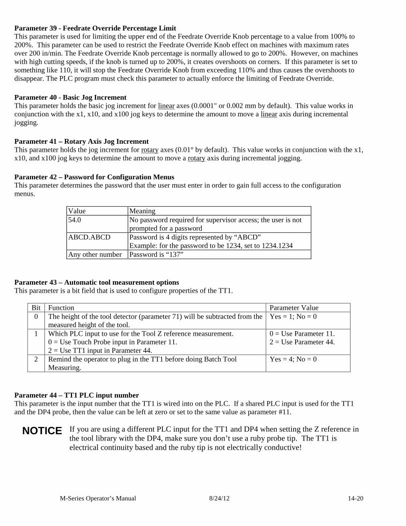
M-Series Operator’s Manual 8/24/12 14-20
Parameter 39 - Feedrate Override Percentage Limit This parameter is used for limiting the upper end of the Feedrate Override Knob percentage to a value from 100% to 200%. This parameter can be used to restrict the Feedrate Override Knob effect on machines with maximum rates over 200 in/min. The Feedrate Override Knob percentage is normally allowed to go to 200%. However, on machines with high cutting speeds, if the knob is turned up to 200%, it creates overshoots on corners. If this parameter is set to something like 110, it will stop the Feedrate Override Knob from exceeding 110% and thus causes the overshoots to disappear. The PLC program must check this parameter to actually enforce the limiting of Feedrate Override.
Parameter 40 - Basic Jog Increment This parameter holds the basic jog increment for linear axes (0.0001" or 0.002 mm by default). This value works in conjunction with the x1, x10, and x100 jog keys to determine the amount to move a linear axis during incremental jogging.
Parameter 41 – Rotary Axis Jog Increment This parameter holds the jog increment for rotary axes (0.01° by default). This value works in conjunction with the x1, x10, and x100 jog keys to determine the amount to move a rotary axis during incremental jogging.
Parameter 42 – Password for Configuration Menus This parameter determines the password that the user must enter in order to gain full access to the configuration menus.
Value Meaning 54.0 No password required for supervisor access; the user is not
prompted for a password ABCD.ABCD Password is 4 digits represented by “ABCD”
Example: for the password to be 1234, set to 1234.1234 Any other number Password is “137”
Parameter 43 – Automatic tool measurement options This parameter is a bit field that is used to configure properties of the TT1.
Bit Function Parameter Value 0 The height of the tool detector (parameter 71) will be subtracted from the
measured height of the tool. Yes = 1; No = 0
1 Which PLC input to use for the Tool Z reference measurement. 0 = Use Touch Probe input in Parameter 11. 2 = Use TT1 input in Parameter 44.
0 = Use Parameter 11. 2 = Use Parameter 44.
2 Remind the operator to plug in the TT1 before doing Batch Tool Measuring.
Yes = 4; No = 0
Parameter 44 – TT1 PLC input number This parameter is the input number that the TT1 is wired into on the PLC. If a shared PLC input is used for the TT1 and the DP4 probe, then the value can be left at zero or set to the same value as parameter #11. NOTICE If you are using a different PLC input for the TT1 and DP4 when setting the Z reference in
the tool library with the DP4, make sure you don’t use a ruby probe tip. The TT1 is electrical continuity based and the ruby tip is not electrically conductive!
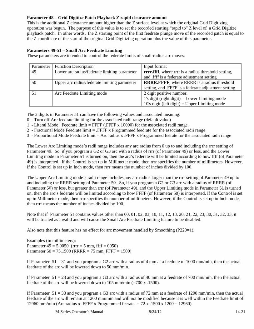
M-Series Operator’s Manual 8/24/12 14-21
Parameter 48 – Grid Digitize Patch Playback Z rapid clearance amount This is the additional Z clearance amount higher than the Z surface level at which the original Grid Digitizing operation was begun. The purpose of this value is to set the recorded starting “rapid to” Z level of a Grid Digitize playback patch. In other words, the Z starting point of the first feedrate plunge move of the recorded patch is equal to the Z coordinate of the start of the original Grid Digitizing operation plus the value of this parameter.
Parameters 49-51 – Small Arc Feedrate Limiting These parameters are intended to control the federate limits of small-radius arc moves.
Parameter Function Description Input format 49 Lower arc radius/federate limiting parameter rrrr.ffff , where rrrr is a radius threshold setting,
and .ffff is a federate adjustment setting 50 Upper arc radius/federate limiting parameter RRRR.FFFF, where RRRR is a radius threshold
setting, and .FFFF is a federate adjustment setting 51 Arc Feedrate Limiting mode 2 digit positive number.
1's digit (right digit) = Lower Limiting mode 10's digit (left digit) = Upper Limiting mode
The 2 digits in Parameter 51 can have the following values and associated meaning: 0 - Turn off Arc feedrate limiting for the associated radii range (default value) 1 - Literal Mode Feedrate limit = FFFF (.FFFF x 10000) for the associated radii range. 2 - Fractional Mode Feedrate limit = .FFFF x Programmed feedrate for the associated radii range 3 - Proportional Mode Feedrate limit = Arc radius x .FFFF x Programmed feerate for the associated radii range The Lower Arc Limiting mode’s radii range includes any arc radius from 0 up to and including the rrrr setting of Parameter 49. So, if you program a G2 or G3 arc with a radius of rrrr (of Parameter 49) or less, and the Lower Limiting mode in Parameter 51 is turned on, then the arc’s federate will be limited according to how ffff (of Parameter 49) is interpreted. If the Control is set up in Millimeter mode, then rrrr specifies the number of millimeters. However, if the Control is set up in Inch mode, then rrrr means the number of inches divided by 100. The Upper Arc Limiting mode’s radii range includes any arc radius larger than the rrrr setting of Parameter 49 up to and including the RRRR setting of Parameter 50. So, if you program a G2 or G3 arc with a radius of RRRR (of Parameter 50) or less, but greater than rrrr (of Parameter 49), and the Upper Limiting mode in Parameter 51 is turned on, then the arc’s federate will be limited according to how FFFF (of Parameter 50) is interpreted. If the Control is set up in Millimeter mode, then rrrr specifies the number of millimeters. However, if the Control is set up in Inch mode, then rrrr means the number of inches divided by 100. Note that if Parameter 51 contains values other than 00, 01, 02, 03, 10, 11, 12, 13, 20, 21, 22, 23, 30, 31, 32, 33, it will be treated as invalid and will cause the Small Arc Feedrate Limiting feature to be disabled. Also note that this feature has no effect for arc movement handled by Smoothing (P220=1). Examples (in millimeters): Parameter 49 = 5.0050 (rrrr = 5 mm, ffff = 0050) Parameter 50 = 75.1500 (RRRR = 75 mm, FFFF = 1500) If Parameter 51 = 31 and you program a G2 arc with a radius of 4 mm at a feedrate of 1000 mm/min, then the actual feedrate of the arc will be lowered down to 50 mm/min. If Parameter 51 = 23 and you program a G3 arc with a radius of 40 mm at a feedrate of 700 mm/min, then the actual feedrate of the arc will be lowered down to 105 mm/min (=700 x .1500). If Parameter 51 = 33 and you program a G3 arc with a radius of 72 mm at a feedrate of 1200 mm/min, then the actual feedrate of the arc will remain at 1200 mm/min and will not be modified because it is well within the Feedrate limit of 12960 mm/min (Arc radius x .FFFF x Programmed feerate = 72 x .1500 x 1200 = 12960).
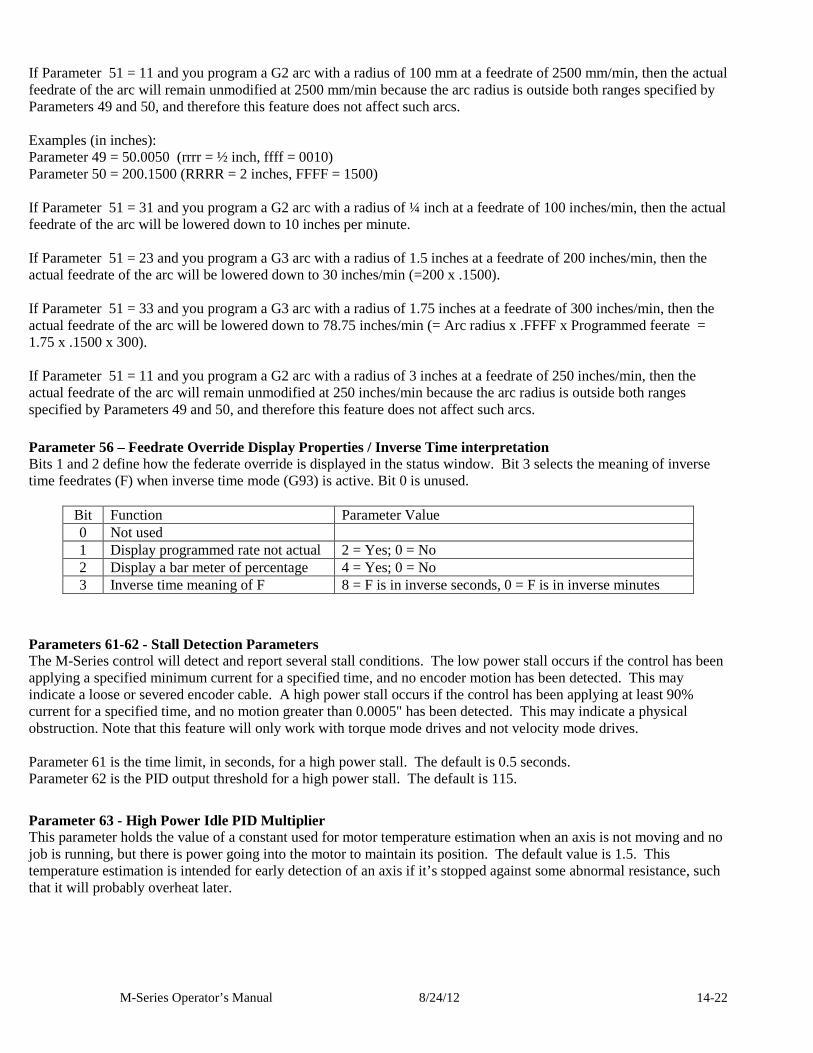
M-Series Operator’s Manual 8/24/12 14-22
If Parameter 51 = 11 and you program a G2 arc with a radius of 100 mm at a feedrate of 2500 mm/min, then the actual feedrate of the arc will remain unmodified at 2500 mm/min because the arc radius is outside both ranges specified by Parameters 49 and 50, and therefore this feature does not affect such arcs. Examples (in inches): Parameter 49 = 50.0050 (rrrr = ½ inch, ffff = 0010) Parameter 50 = 200.1500 (RRRR = 2 inches, FFFF = 1500) If Parameter 51 = 31 and you program a G2 arc with a radius of ¼ inch at a feedrate of 100 inches/min, then the actual feedrate of the arc will be lowered down to 10 inches per minute. If Parameter 51 = 23 and you program a G3 arc with a radius of 1.5 inches at a feedrate of 200 inches/min, then the actual feedrate of the arc will be lowered down to 30 inches/min (=200 x .1500). If Parameter 51 = 33 and you program a G3 arc with a radius of 1.75 inches at a feedrate of 300 inches/min, then the actual feedrate of the arc will be lowered down to 78.75 inches/min (= Arc radius x .FFFF x Programmed feerate = 1.75 x .1500 x 300). If Parameter 51 = 11 and you program a G2 arc with a radius of 3 inches at a feedrate of 250 inches/min, then the actual feedrate of the arc will remain unmodified at 250 inches/min because the arc radius is outside both ranges specified by Parameters 49 and 50, and therefore this feature does not affect such arcs.
Parameter 56 – Feedrate Override Display Properties / Inverse Time interpretation Bits 1 and 2 define how the federate override is displayed in the status window. Bit 3 selects the meaning of inverse time feedrates (F) when inverse time mode (G93) is active. Bit 0 is unused.
Bit Function Parameter Value 0 Not used 1 Display programmed rate not actual 2 = Yes; 0 = No 2 Display a bar meter of percentage 4 = Yes; 0 = No 3 Inverse time meaning of F 8 = F is in inverse seconds, 0 = F is in inverse minutes
Parameters 61-62 - Stall Detection Parameters The M-Series control will detect and report several stall conditions. The low power stall occurs if the control has been applying a specified minimum current for a specified time, and no encoder motion has been detected. This may indicate a loose or severed encoder cable. A high power stall occurs if the control has been applying at least 90% current for a specified time, and no motion greater than 0.0005" has been detected. This may indicate a physical obstruction. Note that this feature will only work with torque mode drives and not velocity mode drives. Parameter 61 is the time limit, in seconds, for a high power stall. The default is 0.5 seconds. Parameter 62 is the PID output threshold for a high power stall. The default is 115.
Parameter 63 - High Power Idle PID Multiplier This parameter holds the value of a constant used for motor temperature estimation when an axis is not moving and no job is running, but there is power going into the motor to maintain its position. The default value is 1.5. This temperature estimation is intended for early detection of an axis if it’s stopped against some abnormal resistance, such that it will probably overheat later.
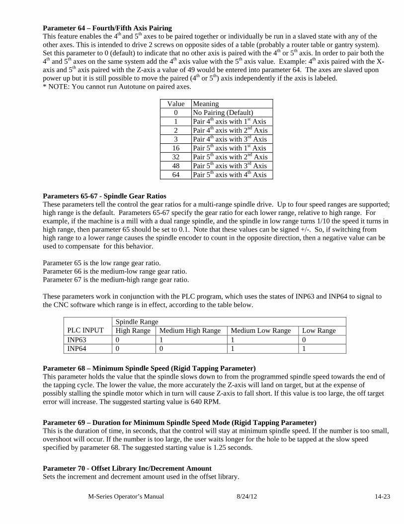
M-Series Operator’s Manual 8/24/12 14-23
Parameter 64 – Fourth/Fifth Axis Pairing This feature enables the 4th and 5th axes to be paired together or individually be run in a slaved state with any of the other axes. This is intended to drive 2 screws on opposite sides of a table (probably a router table or gantry system). Set this parameter to 0 (default) to indicate that no other axis is paired with the 4th or 5th axis. In order to pair both the 4th and 5th axes on the same system add the 4th axis value with the 5th axis value. Example: 4th axis paired with the X-axis and 5th axis paired with the Z-axis a value of 49 would be entered into parameter 64. The axes are slaved upon power up but it is still possible to move the paired (4th or 5th) axis independently if the axis is labeled. * NOTE: You cannot run Autotune on paired axes.
Value Meaning 0 No Pairing (Default) 1 Pair 4th axis with 1st Axis 2 Pair 4th axis with 2nd Axis 3 Pair 4th axis with 3rd Axis 16 Pair 5th axis with 1st Axis 32 Pair 5th axis with 2nd Axis 48 Pair 5th axis with 3rd Axis 64 Pair 5th axis with 4th Axis
Parameters 65-67 - Spindle Gear Ratios These parameters tell the control the gear ratios for a multi-range spindle drive. Up to four speed ranges are supported; high range is the default. Parameters 65-67 specify the gear ratio for each lower range, relative to high range. For example, if the machine is a mill with a dual range spindle, and the spindle in low range turns 1/10 the speed it turns in high range, then parameter 65 should be set to 0.1. Note that these values can be signed +/-. So, if switching from high range to a lower range causes the spindle encoder to count in the opposite direction, then a negative value can be used to compensate for this behavior. Parameter 65 is the low range gear ratio. Parameter 66 is the medium-low range gear ratio. Parameter 67 is the medium-high range gear ratio. These parameters work in conjunction with the PLC program, which uses the states of INP63 and INP64 to signal to the CNC software which range is in effect, according to the table below.
Spindle Range PLC INPUT High Range Medium High Range Medium Low Range Low Range INP63 0 1 1 0 INP64 0 0 1 1
Parameter 68 – Minimum Spindle Speed (Rigid Tapping Parameter) This parameter holds the value that the spindle slows down to from the programmed spindle speed towards the end of the tapping cycle. The lower the value, the more accurately the Z-axis will land on target, but at the expense of possibly stalling the spindle motor which in turn will cause Z-axis to fall short. If this value is too large, the off target error will increase. The suggested starting value is 640 RPM.
Parameter 69 – Duration for Minimum Spindle Speed Mode (Rigid Tapping Parameter) This is the duration of time, in seconds, that the control will stay at minimum spindle speed. If the number is too small, overshoot will occur. If the number is too large, the user waits longer for the hole to be tapped at the slow speed specified by parameter 68. The suggested starting value is 1.25 seconds.
Parameter 70 - Offset Library Inc/Decrement Amount Sets the increment and decrement amount used in the offset library.
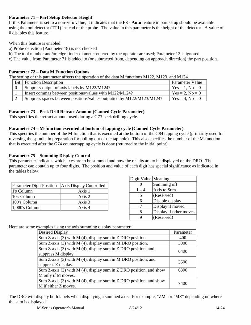
M-Series Operator’s Manual 8/24/12 14-24
Parameter 71 – Part Setup Detector Height If this Parameter is set to a non-zero value, it indicates that the F3 - Auto feature in part setup should be available using the tool detector (TT1) instead of the probe. The value in this parameter is the height of the detector. A value of 0 disables this feature. When this feature is enabled: a) Probe detection (Parameter 18) is not checked b) The tool number and/or edge finder diameter entered by the operator are used; Parameter 12 is ignored. c) The value from Parameter 71 is added to (or subtracted from, depending on approach direction) the part position.
Parameter 72 – Data M Function Options The setting of this parameter affects the operation of the data M functions M122, M123, and M124.
Bit Function Description Parameter Value 0 Suppress output of axis labels by M122/M124? Yes = 1, No = 0 1 Insert commas between positions/values with M122/M124? Yes = 2, No = 0 2 Suppress spaces between positions/values outputted by M122/M123/M124? Yes = 4, No = 0
Parameter 73 – Peck Drill Retract Amount (Canned Cycle Parameter) This specifies the retract amount used during a G73 peck drilling cycle.
Parameter 74 – M-function executed at bottom of tapping cycle (Canned Cycle Parameter) This specifies the number of the M-function that is executed at the bottom of the G84 tapping cycle (primarily used for reversing the spindle in preparation for pulling out of the tap hole). This also specifies the number of the M-function that is executed after the G74 countertapping cycle is done (returned to the initial point).
Parameter 75 – Summing Display Control This parameter indicates which axes are to be summed and how the results are to be displayed on the DRO. The parameter can contain up to four digits. The position and value of each digit has special significance as indicated in the tables below:
Here are some examples using the axis summing display parameter:
Desired Display Parameter Sum Z-axis (3) with M (4), display sum in Z DRO position 400 Sum Z-axis (3) with M (4), display sum in M DRO position. 3000 Sum Z-axis (3) with M (4), display sum in Z DRO position, and suppress M display.
6400
Sum Z-axis (3) with M (4), display sum in M DRO position, and suppress Z display.
3600
Sum Z-axis (3) with M (4), display sum in Z DRO position, and show M only if M moves.
6300
Sum Z-axis (3) with M (4), display sum in Z DRO position, and show M if either Z moves.
7400
The DRO will display both labels when displaying a summed axis. For example, "ZM" or "MZ" depending on where the sum is displayed.
Digit Value Meaning 0 Summing off
1 – 4 Axis to Sum 5 (Reserved) 6 Disable display 7 Display if moved 8 Display if other moves 9 (Reserved)
Parameter Digit Position Axis Display Controlled 1's Column Axis 1 10's Column Axis 2 100's Column Axis 3 1,000's Column Axis 4
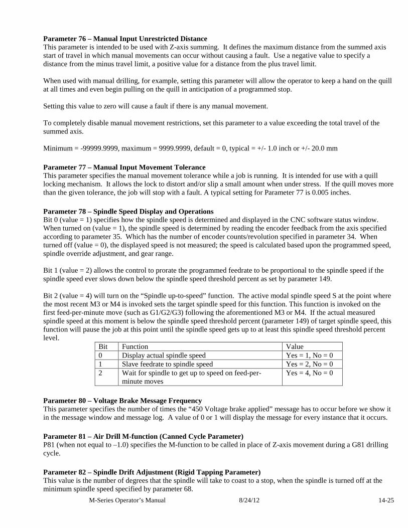
M-Series Operator’s Manual 8/24/12 14-25
Parameter 76 – Manual Input Unrestricted Distance This parameter is intended to be used with Z-axis summing. It defines the maximum distance from the summed axis start of travel in which manual movements can occur without causing a fault. Use a negative value to specify a distance from the minus travel limit, a positive value for a distance from the plus travel limit. When used with manual drilling, for example, setting this parameter will allow the operator to keep a hand on the quill at all times and even begin pulling on the quill in anticipation of a programmed stop. Setting this value to zero will cause a fault if there is any manual movement. To completely disable manual movement restrictions, set this parameter to a value exceeding the total travel of the summed axis. Minimum = -99999.9999, maximum = 9999.9999, default = 0, typical = +/- 1.0 inch or +/- 20.0 mm
Parameter 77 – Manual Input Movement Tolerance This parameter specifies the manual movement tolerance while a job is running. It is intended for use with a quill locking mechanism. It allows the lock to distort and/or slip a small amount when under stress. If the quill moves more than the given tolerance, the job will stop with a fault. A typical setting for Parameter 77 is 0.005 inches.
Parameter 78 – Spindle Speed Display and Operations Bit 0 (value = 1) specifies how the spindle speed is determined and displayed in the CNC software status window. When turned on (value = 1), the spindle speed is determined by reading the encoder feedback from the axis specified according to parameter 35. Which has the number of encoder counts/revolution specified in parameter 34. When turned off (value = 0), the displayed speed is not measured; the speed is calculated based upon the programmed speed, spindle override adjustment, and gear range. Bit 1 (value = 2) allows the control to prorate the programmed feedrate to be proportional to the spindle speed if the spindle speed ever slows down below the spindle speed threshold percent as set by parameter 149. Bit 2 (value = 4) will turn on the “Spindle up-to-speed” function. The active modal spindle speed S at the point where the most recent M3 or M4 is invoked sets the target spindle speed for this function. This function is invoked on the first feed-per-minute move (such as G1/G2/G3) following the aforementioned M3 or M4. If the actual measured spindle speed at this moment is below the spindle speed threshold percent (parameter 149) of target spindle speed, this function will pause the job at this point until the spindle speed gets up to at least this spindle speed threshold percent level.
Bit Function Value 0 Display actual spindle speed Yes = 1, No = 0 1 Slave feedrate to spindle speed Yes = 2, No = 0 2 Wait for spindle to get up to speed on feed-per-
minute moves Yes = 4, No = 0
Parameter 80 – Voltage Brake Message Frequency This parameter specifies the number of times the “450 Voltage brake applied” message has to occur before we show it in the message window and message log. A value of 0 or 1 will display the message for every instance that it occurs.
Parameter 81 – Air Drill M-function (Canned Cycle Parameter) P81 (when not equal to –1.0) specifies the M-function to be called in place of Z-axis movement during a G81 drilling cycle.
Parameter 82 – Spindle Drift Adjustment (Rigid Tapping Parameter) This value is the number of degrees that the spindle will take to coast to a stop, when the spindle is turned off at the minimum spindle speed specified by parameter 68.
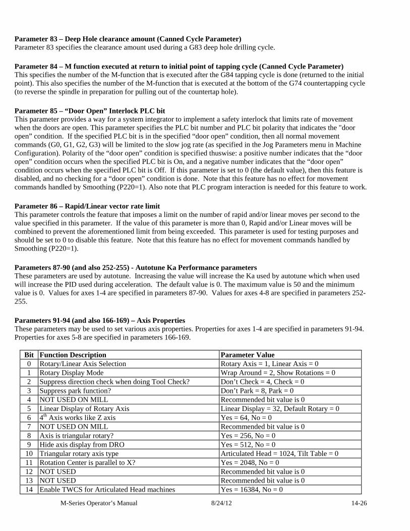
M-Series Operator’s Manual 8/24/12 14-26
Parameter 83 – Deep Hole clearance amount (Canned Cycle Parameter) Parameter 83 specifies the clearance amount used during a G83 deep hole drilling cycle.
Parameter 84 – M function executed at return to initial point of tapping cycle (Canned Cycle Parameter) This specifies the number of the M-function that is executed after the G84 tapping cycle is done (returned to the initial point). This also specifies the number of the M-function that is executed at the bottom of the G74 countertapping cycle (to reverse the spindle in preparation for pulling out of the countertap hole).
Parameter 85 – “Door Open” Interlock PLC bit This parameter provides a way for a system integrator to implement a safety interlock that limits rate of movement when the doors are open. This parameter specifies the PLC bit number and PLC bit polarity that indicates the "door open” condition. If the specified PLC bit is in the specified “door open” condition, then all normal movement commands (G0, G1, G2, G3) will be limited to the slow jog rate (as specified in the Jog Parameters menu in Machine Configuration). Polarity of the “door open” condition is specified thuswise: a positive number indicates that the “door open” condition occurs when the specified PLC bit is On, and a negative number indicates that the “door open” condition occurs when the specified PLC bit is Off. If this parameter is set to 0 (the default value), then this feature is disabled, and no checking for a “door open” condition is done. Note that this feature has no effect for movement commands handled by Smoothing (P220=1). Also note that PLC program interaction is needed for this feature to work.
Parameter 86 – Rapid/Linear vector rate limit This parameter controls the feature that imposes a limit on the number of rapid and/or linear moves per second to the value specified in this parameter. If the value of this parameter is more than 0, Rapid and/or Linear moves will be combined to prevent the aforementioned limit from being exceeded. This parameter is used for testing purposes and should be set to 0 to disable this feature. Note that this feature has no effect for movement commands handled by Smoothing (P220=1).
Parameters 87-90 (and also 252-255) - Autotune Ka Performance parameters These parameters are used by autotune. Increasing the value will increase the Ka used by autotune which when used will increase the PID used during acceleration. The default value is 0. The maximum value is 50 and the minimum value is 0. Values for axes 1-4 are specified in parameters 87-90. Values for axes 4-8 are specified in parameters 252-255.
Parameters 91-94 (and also 166-169) – Axis Properties These parameters may be used to set various axis properties. Properties for axes 1-4 are specified in parameters 91-94. Properties for axes 5-8 are specified in parameters 166-169.
Bit Function Description Parameter Value 0 Rotary/Linear Axis Selection Rotary Axis = 1, Linear Axis = 0 1 Rotary Display Mode Wrap Around = 2, Show Rotations = 0 2 Suppress direction check when doing Tool Check? Don’t Check = 4, Check = 0 3 Suppress park function? Don’t Park = 8, Park = 0 4 NOT USED ON MILL Recommended bit value is 0 5 Linear Display of Rotary Axis Linear Display = 32, Default Rotary = 0 6 4th Axis works like Z axis Yes = 64, No = 0 7 NOT USED ON MILL Recommended bit value is 0 8 Axis is triangular rotary? Yes = 256, No = 0 9 Hide axis display from DRO Yes = 512, No = 0 10 Triangular rotary axis type Articulated Head = 1024, Tilt Table = 0 11 Rotation Center is parallel to X? Yes = 2048, No = 0 12 NOT USED Recommended bit value is 0 13 NOT USED Recommended bit value is 0 14 Enable TWCS for Articulated Head machines Yes = 16384, No = 0
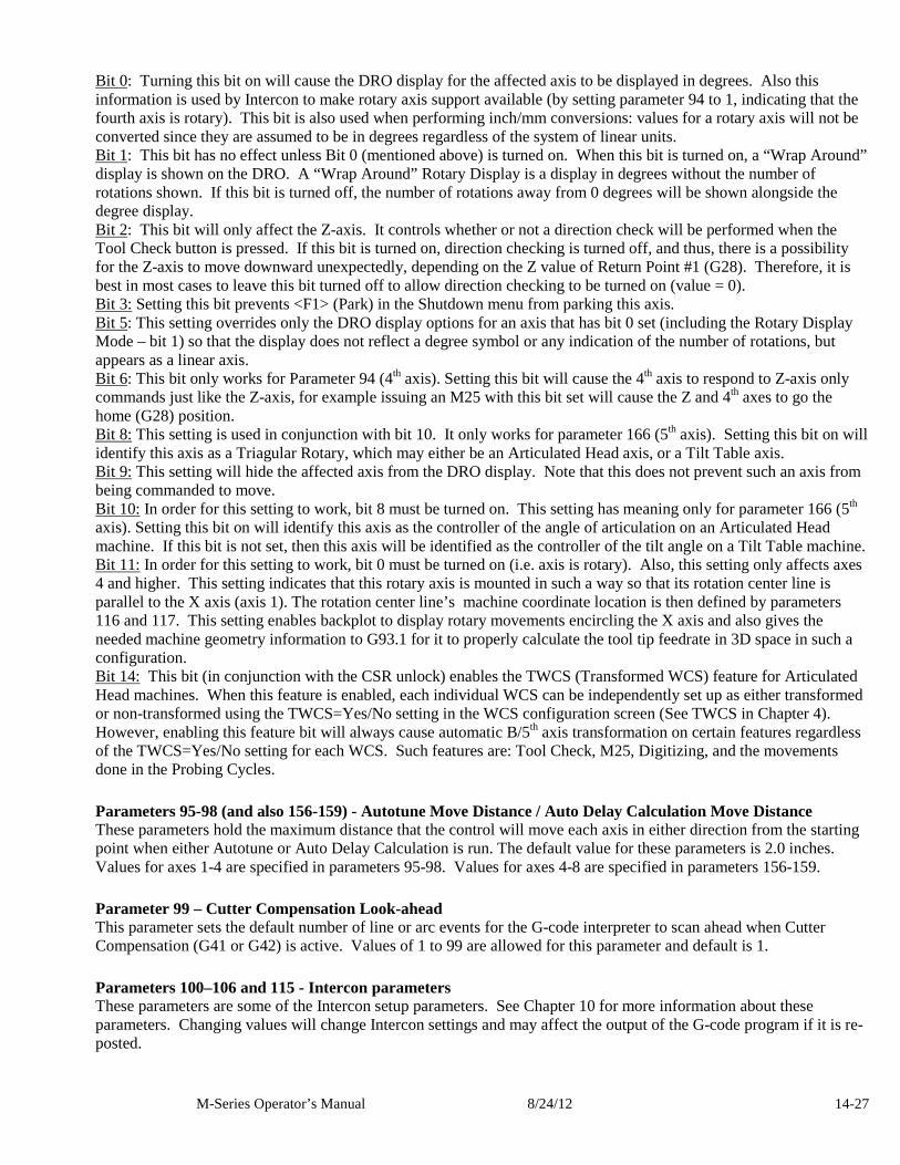
M-Series Operator’s Manual 8/24/12 14-27
Bit 0: Turning this bit on will cause the DRO display for the affected axis to be displayed in degrees. Also this information is used by Intercon to make rotary axis support available (by setting parameter 94 to 1, indicating that the fourth axis is rotary). This bit is also used when performing inch/mm conversions: values for a rotary axis will not be converted since they are assumed to be in degrees regardless of the system of linear units. Bit 1: This bit has no effect unless Bit 0 (mentioned above) is turned on. When this bit is turned on, a “Wrap Around” display is shown on the DRO. A “Wrap Around” Rotary Display is a display in degrees without the number of rotations shown. If this bit is turned off, the number of rotations away from 0 degrees will be shown alongside the degree display. Bit 2: This bit will only affect the Z-axis. It controls whether or not a direction check will be performed when the Tool Check button is pressed. If this bit is turned on, direction checking is turned off, and thus, there is a possibility for the Z-axis to move downward unexpectedly, depending on the Z value of Return Point #1 (G28). Therefore, it is best in most cases to leave this bit turned off to allow direction checking to be turned on (value = 0). Bit 3: Setting this bit prevents <F1> (Park) in the Shutdown menu from parking this axis. Bit 5: This setting overrides only the DRO display options for an axis that has bit 0 set (including the Rotary Display Mode – bit 1) so that the display does not reflect a degree symbol or any indication of the number of rotations, but appears as a linear axis. Bit 6: This bit only works for Parameter 94 (4th axis). Setting this bit will cause the 4th axis to respond to Z-axis only commands just like the Z-axis, for example issuing an M25 with this bit set will cause the Z and 4th axes to go the home (G28) position. Bit 8: This setting is used in conjunction with bit 10. It only works for parameter 166 (5th axis). Setting this bit on will identify this axis as a Triagular Rotary, which may either be an Articulated Head axis, or a Tilt Table axis. Bit 9: This setting will hide the affected axis from the DRO display. Note that this does not prevent such an axis from being commanded to move. Bit 10: In order for this setting to work, bit 8 must be turned on. This setting has meaning only for parameter 166 (5th axis). Setting this bit on will identify this axis as the controller of the angle of articulation on an Articulated Head machine. If this bit is not set, then this axis will be identified as the controller of the tilt angle on a Tilt Table machine. Bit 11: In order for this setting to work, bit 0 must be turned on (i.e. axis is rotary). Also, this setting only affects axes 4 and higher. This setting indicates that this rotary axis is mounted in such a way so that its rotation center line is parallel to the X axis (axis 1). The rotation center line’s machine coordinate location is then defined by parameters 116 and 117. This setting enables backplot to display rotary movements encircling the X axis and also gives the needed machine geometry information to G93.1 for it to properly calculate the tool tip feedrate in 3D space in such a configuration. Bit 14: This bit (in conjunction with the CSR unlock) enables the TWCS (Transformed WCS) feature for Articulated Head machines. When this feature is enabled, each individual WCS can be independently set up as either transformed or non-transformed using the TWCS=Yes/No setting in the WCS configuration screen (See TWCS in Chapter 4). However, enabling this feature bit will always cause automatic B/5th axis transformation on certain features regardless of the TWCS=Yes/No setting for each WCS. Such features are: Tool Check, M25, Digitizing, and the movements done in the Probing Cycles.
Parameters 95-98 (and also 156-159) - Autotune Move Distance / Auto Delay Calculation Move Distance These parameters hold the maximum distance that the control will move each axis in either direction from the starting point when either Autotune or Auto Delay Calculation is run. The default value for these parameters is 2.0 inches. Values for axes 1-4 are specified in parameters 95-98. Values for axes 4-8 are specified in parameters 156-159.
Parameter 99 – Cutter Compensation Look-ahead This parameter sets the default number of line or arc events for the G-code interpreter to scan ahead when Cutter Compensation (G41 or G42) is active. Values of 1 to 99 are allowed for this parameter and default is 1.
Parameters 100–106 and 115 - Intercon parameters These parameters are some of the Intercon setup parameters. See Chapter 10 for more information about these parameters. Changing values will change Intercon settings and may affect the output of the G-code program if it is re-posted.
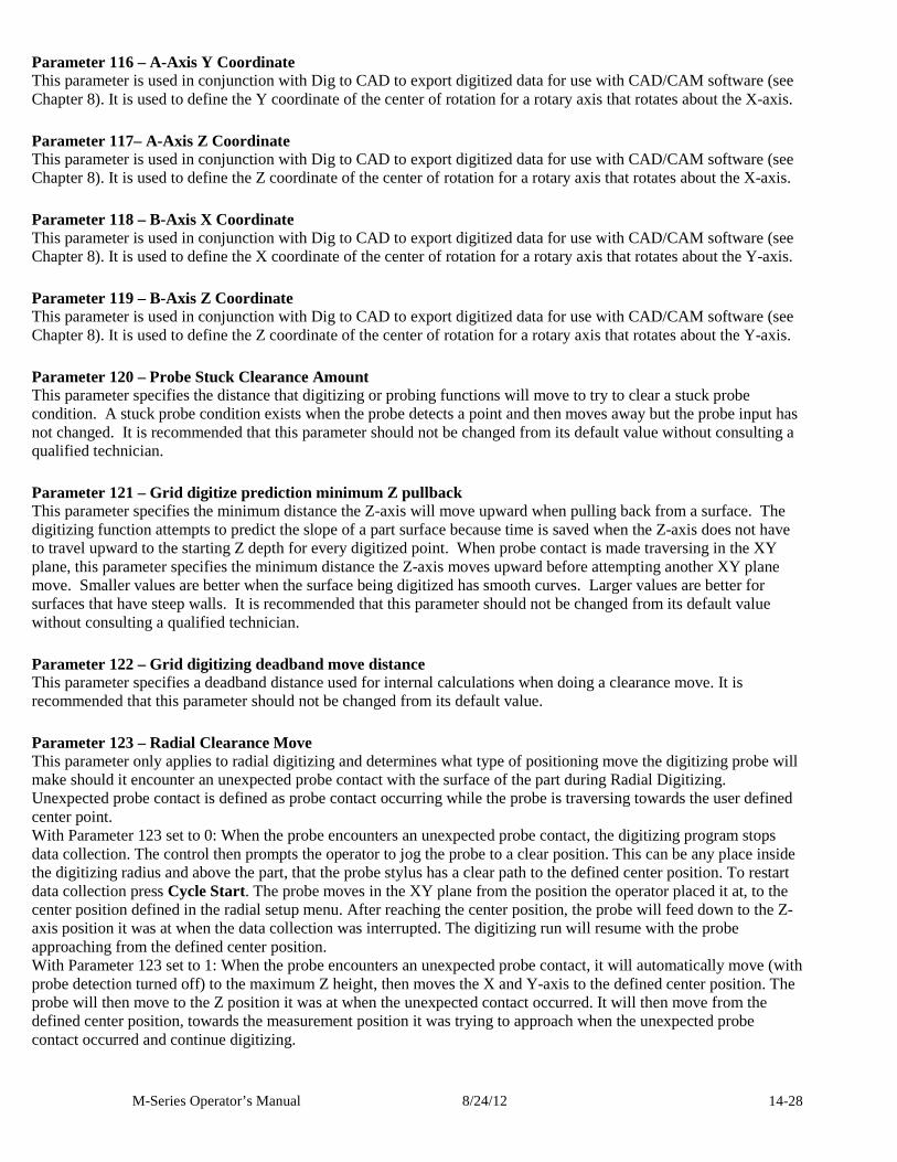
M-Series Operator’s Manual 8/24/12 14-28
Parameter 116 – A-Axis Y Coordinate This parameter is used in conjunction with Dig to CAD to export digitized data for use with CAD/CAM software (see Chapter 8). It is used to define the Y coordinate of the center of rotation for a rotary axis that rotates about the X-axis.
Parameter 117– A-Axis Z Coordinate This parameter is used in conjunction with Dig to CAD to export digitized data for use with CAD/CAM software (see Chapter 8). It is used to define the Z coordinate of the center of rotation for a rotary axis that rotates about the X-axis.
Parameter 118 – B-Axis X Coordinate This parameter is used in conjunction with Dig to CAD to export digitized data for use with CAD/CAM software (see Chapter 8). It is used to define the X coordinate of the center of rotation for a rotary axis that rotates about the Y-axis.
Parameter 119 – B-Axis Z Coordinate This parameter is used in conjunction with Dig to CAD to export digitized data for use with CAD/CAM software (see Chapter 8). It is used to define the Z coordinate of the center of rotation for a rotary axis that rotates about the Y-axis.
Parameter 120 – Probe Stuck Clearance Amount This parameter specifies the distance that digitizing or probing functions will move to try to clear a stuck probe condition. A stuck probe condition exists when the probe detects a point and then moves away but the probe input has not changed. It is recommended that this parameter should not be changed from its default value without consulting a qualified technician.
Parameter 121 – Grid digitize prediction minimum Z pullback This parameter specifies the minimum distance the Z-axis will move upward when pulling back from a surface. The digitizing function attempts to predict the slope of a part surface because time is saved when the Z-axis does not have to travel upward to the starting Z depth for every digitized point. When probe contact is made traversing in the XY plane, this parameter specifies the minimum distance the Z-axis moves upward before attempting another XY plane move. Smaller values are better when the surface being digitized has smooth curves. Larger values are better for surfaces that have steep walls. It is recommended that this parameter should not be changed from its default value without consulting a qualified technician.
Parameter 122 – Grid digitizing deadband move distance This parameter specifies a deadband distance used for internal calculations when doing a clearance move. It is recommended that this parameter should not be changed from its default value.
Parameter 123 – Radial Clearance Move This parameter only applies to radial digitizing and determines what type of positioning move the digitizing probe will make should it encounter an unexpected probe contact with the surface of the part during Radial Digitizing. Unexpected probe contact is defined as probe contact occurring while the probe is traversing towards the user defined center point. With Parameter 123 set to 0: When the probe encounters an unexpected probe contact, the digitizing program stops data collection. The control then prompts the operator to jog the probe to a clear position. This can be any place inside the digitizing radius and above the part, that the probe stylus has a clear path to the defined center position. To restart data collection press Cycle Start. The probe moves in the XY plane from the position the operator placed it at, to the center position defined in the radial setup menu. After reaching the center position, the probe will feed down to the Z-axis position it was at when the data collection was interrupted. The digitizing run will resume with the probe approaching from the defined center position. With Parameter 123 set to 1: When the probe encounters an unexpected probe contact, it will automatically move (with probe detection turned off) to the maximum Z height, then moves the X and Y-axis to the defined center position. The probe will then move to the Z position it was at when the unexpected contact occurred. It will then move from the defined center position, towards the measurement position it was trying to approach when the unexpected probe contact occurred and continue digitizing.
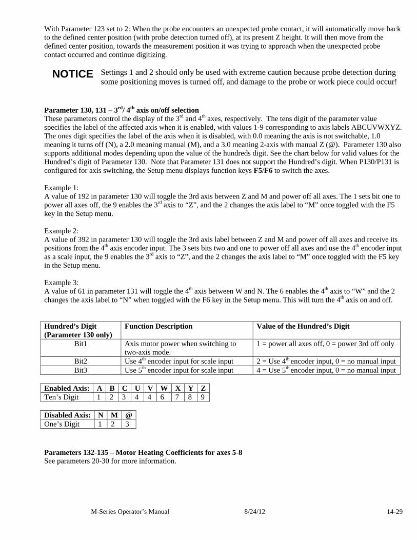
M-Series Operator’s Manual 8/24/12 14-29
With Parameter 123 set to 2: When the probe encounters an unexpected probe contact, it will automatically move back to the defined center position (with probe detection turned off), at its present Z height. It will then move from the defined center position, towards the measurement position it was trying to approach when the unexpected probe contact occurred and continue digitizing. NOTICE Settings 1 and 2 should only be used with extreme caution because probe detection during
some positioning moves is turned off, and damage to the probe or work piece could occur!
Parameter 130, 131 – 3rd/ 4th axis on/off selection These parameters control the display of the 3rd and 4th axes, respectively. The tens digit of the parameter value specifies the label of the affected axis when it is enabled, with values 1-9 corresponding to axis labels ABCUVWXYZ. The ones digit specifies the label of the axis when it is disabled, with 0.0 meaning the axis is not switchable, 1.0 meaning it turns off (N), a 2.0 meaning manual (M), and a 3.0 meaning 2-axis with manual Z (@). Parameter 130 also supports additional modes depending upon the value of the hundreds digit. See the chart below for valid values for the Hundred’s digit of Parameter 130. Note that Parameter 131 does not support the Hundred’s digit. When P130/P131 is configured for axis switching, the Setup menu displays function keys F5/F6 to switch the axes. Example 1: A value of 192 in parameter 130 will toggle the 3rd axis between Z and M and power off all axes. The 1 sets bit one to power all axes off, the 9 enables the 3rd axis to “Z”, and the 2 changes the axis label to “M” once toggled with the F5 key in the Setup menu. Example 2: A value of 392 in parameter 130 will toggle the 3rd axis label between Z and M and power off all axes and receive its positions from the 4th axis encoder input. The 3 sets bits two and one to power off all axes and use the 4th encoder input as a scale input, the 9 enables the 3rd axis to “Z”, and the 2 changes the axis label to “M” once toggled with the F5 key in the Setup menu. Example 3: A value of 61 in parameter 131 will toggle the 4th axis between W and N. The 6 enables the 4th axis to “W” and the 2 changes the axis label to “N” when toggled with the F6 key in the Setup menu. This will turn the 4th axis on and off. Hundred’s Digit (Parameter 130 only)
Function Description Value of the Hundred’s Digit
Bit1 Axis motor power when switching to two-axis mode.
1 = power all axes off, 0 = power 3rd off only
Bit2 Use 4th encoder input for scale input 2 = Use 4th encoder input, 0 = no manual input Bit3 Use 5th encoder input for scale input 4 = Use 5th encoder input, 0 = no manual input
Enabled Axis: A B C U V W X Y Z Ten’s Digit 1 2 3 4 4 6 7 8 9 Disabled Axis: N M @ One’s Digit 1 2 3
Parameters 132-135 – Motor Heating Coefficients for axes 5-8 See parameters 20-30 for more information.
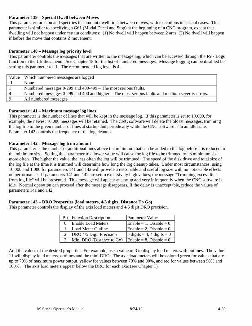
M-Series Operator’s Manual 8/24/12 14-30
Parameter 139 – Special Dwell between Moves This parameter turns on and specifies the amount dwell time between moves, with exceptions in special cases. This parameter is similar to specifying a G61 (Modal Decel and Stop) at the beginning of a CNC program, except that dwelling will not happen under certain conditions: (1) No dwell will happen between 2 arcs. (2) No dwell will happen if before the move that contains Z movement.
Parameter 140 – Message log priority level This parameter controls the messages that are written to the message log, which can be accessed through the F9 - Logs function in the Utilities menu. See Chapter 15 for the list of numbered messages. Message logging can be disabled be setting this parameter to -1. The recommended log level is 4. Value Which numbered messages are logged -1 None 1 Numbered messages 0-299 and 400-499 – The most serious faults. 4 Numbered messages 0-299 and 400 and higher – The most serious faults and medium severity errors. 9 All numbered messages
Parameter 141 – Maximum message log lines This parameter is the number of lines that will be kept in the message log. If this parameter is set to 10,000, for example, the newest 10,000 messages will be retained. The CNC software will delete the oldest messages, trimming the log file to the given number of lines at startup and periodically while the CNC software is in an idle state. Parameter 142 controls the frequency of the log cleanup.
Parameter 142 – Message log trim amount This parameter is the number of additional lines above the minimum that can be added to the log before it is reduced to the minimum size. Setting this parameter to a lower value will cause the log file to be trimmed to its minimum size more often. The higher the value, the less often the log will be trimmed. The speed of the disk drive and total size of the log file at the time it is trimmed will determine how long the log cleanup takes. Under most circumstances, using 10,000 and 1,000 for parameters 141 and 142 will provide a reasonable and useful log size with no noticeable effects on performance. If parameters 141 and 142 are set to excessively high values, the message "Trimming excess lines from log file" will be presented. This message will appear at startup and very infrequently when the CNC software is idle. Normal operation can proceed after the message disappears. If the delay is unacceptable, reduce the values of parameters 141 and 142.
Parameter 143 – DRO Properties (load meters, 4/5 digits, Distance To Go) This parameter controls the display of the axis load meters and 4/5 digit DRO precision.
Bit Function Description Parameter Value 0 Enable Load Meters Enable = 1, Disable = 0 1 Load Meter Outline Enable = 2, Disable = 0 2 DRO 4/5 Digit Precision 5 digits = 4, 4 digits = 0 3 Mini DRO (Distance to Go) Enable = 8, Disable = 0
Add the values of the desired properties. For example, use a value of 3 to display load meters with outlines. The value 11 will display load meters, outlines and the mini-DRO. The axis load meters will be colored green for values that are up to 70% of maximum power output, yellow for values between 70% and 90%, and red for values between 90% and 100%. The axis load meters appear below the DRO for each axis (see Chapter 1).
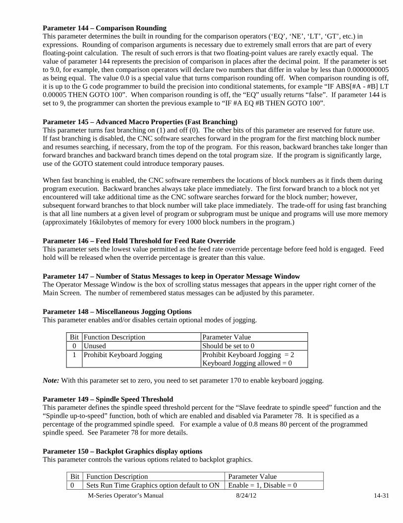
M-Series Operator’s Manual 8/24/12 14-31
Parameter 144 – Comparison Rounding This parameter determines the built in rounding for the comparison operators (‘EQ’, ‘NE’, ‘LT’, ‘GT’, etc.) in expressions. Rounding of comparison arguments is necessary due to extremely small errors that are part of every floating-point calculation. The result of such errors is that two floating-point values are rarely exactly equal. The value of parameter 144 represents the precision of comparison in places after the decimal point. If the parameter is set to 9.0, for example, then comparison operators will declare two numbers that differ in value by less than 0.0000000005 as being equal. The value 0.0 is a special value that turns comparison rounding off. When comparison rounding is off, it is up to the G code programmer to build the precision into conditional statements, for example “IF ABS[#A - #B] LT 0.00005 THEN GOTO 100”. When comparison rounding is off, the “EQ” usually returns “false”. If parameter 144 is set to 9, the programmer can shorten the previous example to “IF #A EQ #B THEN GOTO 100”.
Parameter 145 – Advanced Macro Properties (Fast Branching) This parameter turns fast branching on (1) and off (0). The other bits of this parameter are reserved for future use. If fast branching is disabled, the CNC software searches forward in the program for the first matching block number and resumes searching, if necessary, from the top of the program. For this reason, backward branches take longer than forward branches and backward branch times depend on the total program size. If the program is significantly large, use of the GOTO statement could introduce temporary pauses. When fast branching is enabled, the CNC software remembers the locations of block numbers as it finds them during program execution. Backward branches always take place immediately. The first forward branch to a block not yet encountered will take additional time as the CNC software searches forward for the block number; however, subsequent forward branches to that block number will take place immediately. The trade-off for using fast branching is that all line numbers at a given level of program or subprogram must be unique and programs will use more memory (approximately 16kilobytes of memory for every 1000 block numbers in the program.)
Parameter 146 – Feed Hold Threshold for Feed Rate Override This parameter sets the lowest value permitted as the feed rate override percentage before feed hold is engaged. Feed hold will be released when the override percentage is greater than this value.
Parameter 147 – Number of Status Messages to keep in Operator Message Window The Operator Message Window is the box of scrolling status messages that appears in the upper right corner of the Main Screen. The number of remembered status messages can be adjusted by this parameter.
Parameter 148 – Miscellaneous Jogging Options This parameter enables and/or disables certain optional modes of jogging.
Bit Function Description Parameter Value 0 Unused Should be set to 0 1 Prohibit Keyboard Jogging Prohibit Keyboard Jogging = 2
Keyboard Jogging allowed = 0 Note: With this parameter set to zero, you need to set parameter 170 to enable keyboard jogging.
Parameter 149 – Spindle Speed Threshold This parameter defines the spindle speed threshold percent for the “Slave feedrate to spindle speed” function and the “Spindle up-to-speed” function, both of which are enabled and disabled via Parameter 78. It is specified as a percentage of the programmed spindle speed. For example a value of 0.8 means 80 percent of the programmed spindle speed. See Parameter 78 for more details.
Parameter 150 – Backplot Graphics display options This parameter controls the various options related to backplot graphics.
Bit Function Description Parameter Value 0 Sets Run Time Graphics option default to ON Enable = 1, Disable = 0
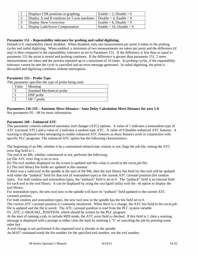
M-Series Operator’s Manual 8/24/12 14-32
1 Displays CSR positions in graphing Enable = 2, Disable = 0 2 Display A and B rotations for 5 axis machines Disable = 4, Enable = 0 3 Display Skew Correction Enable = 8, Disable = 0 4 Display Lash/Screw Compensation Enable = 16, Disable = 0
Parameter 151 – Repeatability tolerance for probing and radial digitizing. Default is 0, repeatability check disabled. When disabled, only one measurement per point is taken in the probing cycles and radial digitizing. When enabled, a minimum of two measurements are taken per point and the difference (if any) is then compared to the repeatability tolerance as set in Parameter 151. If the difference is less than or equal to parameter 151 the point is stored and probing continues. If the difference is greater than parameter 151, 2 more measurements are taken and the process repeated up to a maximum of 10 times. In probing cycles, if the repeatability tolerance cannot be met the cycle is cancelled and an error message generated. In radial digitizing, the point is discarded and digitizing continues without interruption.
Parameter 155 – Probe Type This parameter specifies the type of probe being used.
Value Meaning 0 Standard Mechanical probe 1 DSP probe 2 DP-7 probe
Parameters 156-159 – Autotune Move Distance / Auto Delay Calculation Move Distance for axes 5-8 See parameters 95 – 98 for more information.
Parameter 160 – Enhanced ATC This parameter controls enhanced automatic tool changer (ATC) options. A value of 1 indicates a nonrandom type of ATC (carousel ATC) and a value of 2 indicates a random type ATC. A value of 0 disables enhanced ATC features. A warning is displayed when attempting to enable enhanced ATC features as these features work in conjunction with specific PLC programs. The enhanced ATC option has the following characteristics: The beginning of an M6, whether it be a customized mfunc6.mac routine or not, flags the job file, setting the ATC error flag field to 1. The end of an M6, whether customized or not, performs the following: (a) The ATC error flag is set to zero. (b) The tool number displayed on the screen is updated and this value is saved in the cncm.job file. (c) The tool library bin fields are updated in this manner: If there was a valid tool in the spindle at the start of the M6, then the tool library bin field for this tool will be updated with either the “putback” field for that tool (if nonrandom type) or the current ATC carousel position (for random type). For both random and nonrandom types, the “putback” field is set to 0. The “putback” field is an internal field for each tool in the tool library. It can be displayed by using the cnccfgutil utility with the –dt option to display the tool library. For nonrandom types, the new tool now in the spindle will have its “putback” field updated to the current ATC carousel position. For both random and nonrandom types, the new tool now in the spindle has the bin field set to 0. The current ATC carousel position is constantly monitored. When there is a change, the ATC bin field in the cncm.job file is updated and the file is saved. The ATC carousel position is read from the PLC system variable SV_ATC_CAROUSEL_POSITION, which should be written by the PLC program. At the start of running a job, to include MDI mode, the ATC error field is checked. If this field is 1, then a warning message is displayed with a prompt to either clear the fault by entering a ‘Y’ or canceling the job by pressing some other key. A tool change is not performed if the requested tool is already in the spindle. An M107 command sends the bin number for the specified tool number, not the tool number.
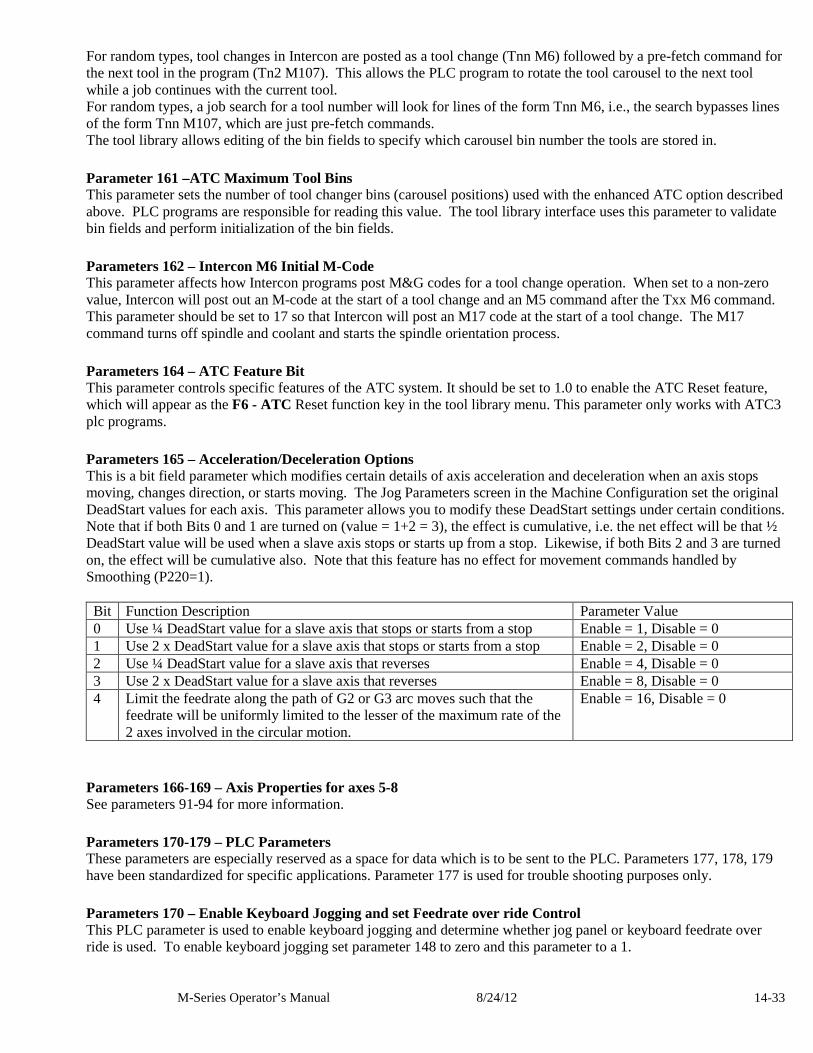
M-Series Operator’s Manual 8/24/12 14-33
For random types, tool changes in Intercon are posted as a tool change (Tnn M6) followed by a pre-fetch command for the next tool in the program (Tn2 M107). This allows the PLC program to rotate the tool carousel to the next tool while a job continues with the current tool. For random types, a job search for a tool number will look for lines of the form Tnn M6, i.e., the search bypasses lines of the form Tnn M107, which are just pre-fetch commands. The tool library allows editing of the bin fields to specify which carousel bin number the tools are stored in.
Parameter 161 –ATC Maximum Tool Bins This parameter sets the number of tool changer bins (carousel positions) used with the enhanced ATC option described above. PLC programs are responsible for reading this value. The tool library interface uses this parameter to validate bin fields and perform initialization of the bin fields.
Parameters 162 – Intercon M6 Initial M-Code This parameter affects how Intercon programs post M&G codes for a tool change operation. When set to a non-zero value, Intercon will post out an M-code at the start of a tool change and an M5 command after the Txx M6 command. This parameter should be set to 17 so that Intercon will post an M17 code at the start of a tool change. The M17 command turns off spindle and coolant and starts the spindle orientation process.
Parameters 164 – ATC Feature Bit This parameter controls specific features of the ATC system. It should be set to 1.0 to enable the ATC Reset feature, which will appear as the F6 - ATC Reset function key in the tool library menu. This parameter only works with ATC3 plc programs.
Parameters 165 – Acceleration/Deceleration Options This is a bit field parameter which modifies certain details of axis acceleration and deceleration when an axis stops moving, changes direction, or starts moving. The Jog Parameters screen in the Machine Configuration set the original DeadStart values for each axis. This parameter allows you to modify these DeadStart settings under certain conditions. Note that if both Bits 0 and 1 are turned on (value = 1+2 = 3), the effect is cumulative, i.e. the net effect will be that ½ DeadStart value will be used when a slave axis stops or starts up from a stop. Likewise, if both Bits 2 and 3 are turned on, the effect will be cumulative also. Note that this feature has no effect for movement commands handled by Smoothing (P220=1). Bit Function Description Parameter Value 0 Use ¼ DeadStart value for a slave axis that stops or starts from a stop Enable = 1, Disable = 0 1 Use 2 x DeadStart value for a slave axis that stops or starts from a stop Enable = 2, Disable = 0 2 Use ¼ DeadStart value for a slave axis that reverses Enable = 4, Disable = 0 3 Use 2 x DeadStart value for a slave axis that reverses Enable = 8, Disable = 0 4 Limit the feedrate along the path of G2 or G3 arc moves such that the
feedrate will be uniformly limited to the lesser of the maximum rate of the 2 axes involved in the circular motion.
Enable = 16, Disable = 0
Parameters 166-169 – Axis Properties for axes 5-8 See parameters 91-94 for more information.
Parameters 170-179 – PLC Parameters These parameters are especially reserved as a space for data which is to be sent to the PLC. Parameters 177, 178, 179 have been standardized for specific applications. Parameter 177 is used for trouble shooting purposes only.
Parameters 170 – Enable Keyboard Jogging and set Feedrate over ride Control This PLC parameter is used to enable keyboard jogging and determine whether jog panel or keyboard feedrate over ride is used. To enable keyboard jogging set parameter 148 to zero and this parameter to a 1.
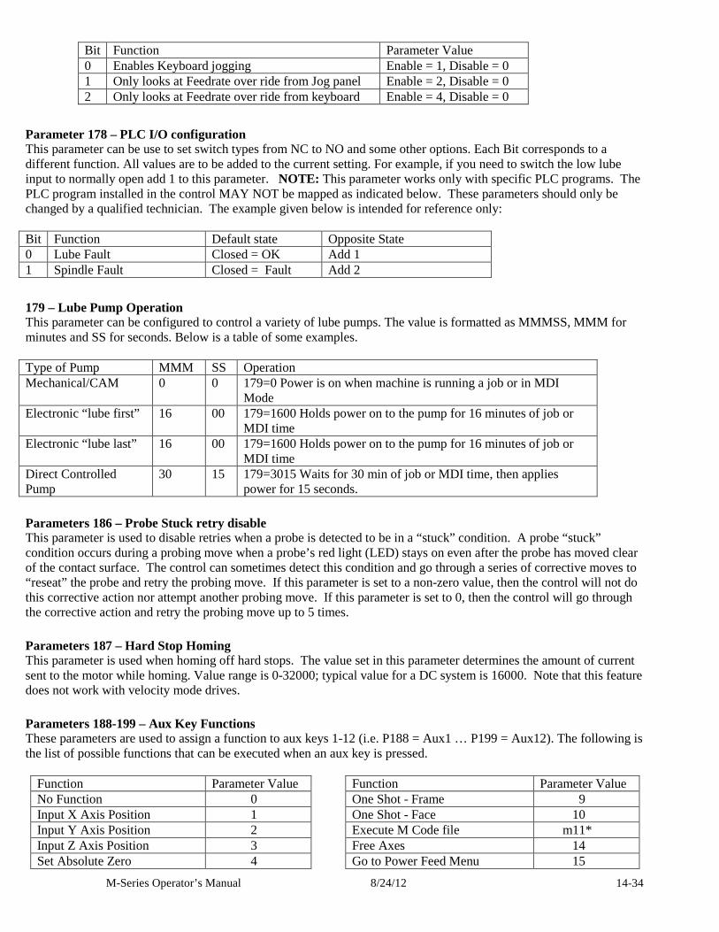
M-Series Operator’s Manual 8/24/12 14-34
Bit Function Parameter Value 0 Enables Keyboard jogging Enable = 1, Disable = 0 1 Only looks at Feedrate over ride from Jog panel Enable = 2, Disable = 0 2 Only looks at Feedrate over ride from keyboard Enable = 4, Disable = 0
Parameter 178 – PLC I/O configuration This parameter can be use to set switch types from NC to NO and some other options. Each Bit corresponds to a different function. All values are to be added to the current setting. For example, if you need to switch the low lube input to normally open add 1 to this parameter. NOTE: This parameter works only with specific PLC programs. The PLC program installed in the control MAY NOT be mapped as indicated below. These parameters should only be changed by a qualified technician. The example given below is intended for reference only: Bit Function Default state Opposite State 0 Lube Fault Closed = OK Add 1 1 Spindle Fault Closed = Fault Add 2
179 – Lube Pump Operation This parameter can be configured to control a variety of lube pumps. The value is formatted as MMMSS, MMM for minutes and SS for seconds. Below is a table of some examples. Type of Pump MMM SS Operation Mechanical/CAM 0 0 179=0 Power is on when machine is running a job or in MDI
Mode Electronic “lube first” 16 00 179=1600 Holds power on to the pump for 16 minutes of job or
MDI time Electronic “lube last” 16 00 179=1600 Holds power on to the pump for 16 minutes of job or
MDI time Direct Controlled Pump
30 15 179=3015 Waits for 30 min of job or MDI time, then applies power for 15 seconds.
Parameters 186 – Probe Stuck retry disable This parameter is used to disable retries when a probe is detected to be in a “stuck” condition. A probe “stuck” condition occurs during a probing move when a probe’s red light (LED) stays on even after the probe has moved clear of the contact surface. The control can sometimes detect this condition and go through a series of corrective moves to “reseat” the probe and retry the probing move. If this parameter is set to a non-zero value, then the control will not do this corrective action nor attempt another probing move. If this parameter is set to 0, then the control will go through the corrective action and retry the probing move up to 5 times.
Parameters 187 – Hard Stop Homing This parameter is used when homing off hard stops. The value set in this parameter determines the amount of current sent to the motor while homing. Value range is 0-32000; typical value for a DC system is 16000. Note that this feature does not work with velocity mode drives.
Parameters 188-199 – Aux Key Functions These parameters are used to assign a function to aux keys 1-12 (i.e. P188 = Aux1 … P199 = Aux12). The following is the list of possible functions that can be executed when an aux key is pressed.
Function Parameter Value Function Parameter Value No Function 0 One Shot - Frame 9 Input X Axis Position 1 One Shot - Face 10 Input Y Axis Position 2 Execute M Code file m11* Input Z Axis Position 3 Free Axes 14 Set Absolute Zero 4
Go to Power Feed Menu 15
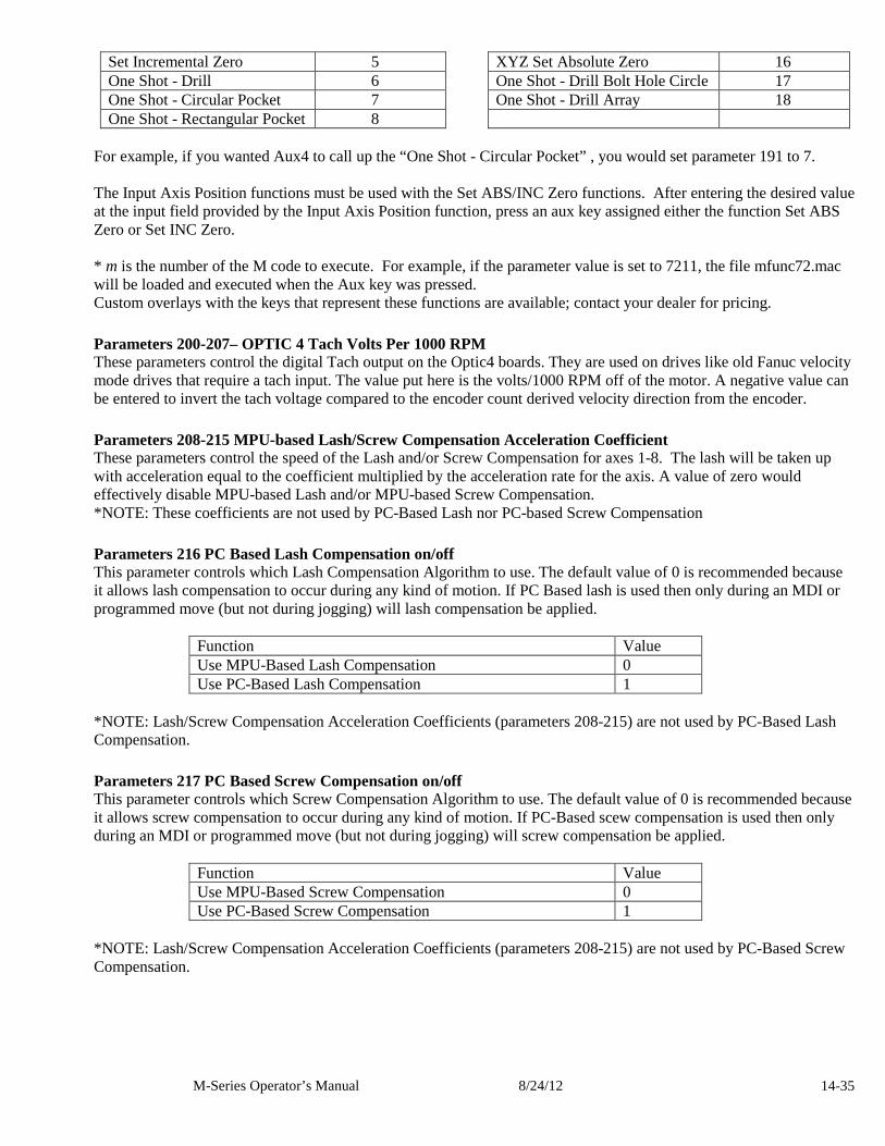
M-Series Operator’s Manual 8/24/12 14-35
Set Incremental Zero 5 XYZ Set Absolute Zero 16 One Shot - Drill 6 One Shot - Drill Bolt Hole Circle 17 One Shot - Circular Pocket 7 One Shot - Drill Array 18 One Shot - Rectangular Pocket 8
For example, if you wanted Aux4 to call up the “One Shot - Circular Pocket” , you would set parameter 191 to 7. The Input Axis Position functions must be used with the Set ABS/INC Zero functions. After entering the desired value at the input field provided by the Input Axis Position function, press an aux key assigned either the function Set ABS Zero or Set INC Zero. * m is the number of the M code to execute. For example, if the parameter value is set to 7211, the file mfunc72.mac will be loaded and executed when the Aux key was pressed. Custom overlays with the keys that represent these functions are available; contact your dealer for pricing.
Parameters 200-207– OPTIC 4 Tach Volts Per 1000 RPM These parameters control the digital Tach output on the Optic4 boards. They are used on drives like old Fanuc velocity mode drives that require a tach input. The value put here is the volts/1000 RPM off of the motor. A negative value can be entered to invert the tach voltage compared to the encoder count derived velocity direction from the encoder.
Parameters 208-215 MPU-based Lash/Screw Compensation Acceleration Coefficient These parameters control the speed of the Lash and/or Screw Compensation for axes 1-8. The lash will be taken up with acceleration equal to the coefficient multiplied by the acceleration rate for the axis. A value of zero would effectively disable MPU-based Lash and/or MPU-based Screw Compensation. *NOTE: These coefficients are not used by PC-Based Lash nor PC-based Screw Compensation
Parameters 216 PC Based Lash Compensation on/off This parameter controls which Lash Compensation Algorithm to use. The default value of 0 is recommended because it allows lash compensation to occur during any kind of motion. If PC Based lash is used then only during an MDI or programmed move (but not during jogging) will lash compensation be applied.
Function Value Use MPU-Based Lash Compensation 0 Use PC-Based Lash Compensation 1
*NOTE: Lash/Screw Compensation Acceleration Coefficients (parameters 208-215) are not used by PC-Based Lash Compensation.
Parameters 217 PC Based Screw Compensation on/off This parameter controls which Screw Compensation Algorithm to use. The default value of 0 is recommended because it allows screw compensation to occur during any kind of motion. If PC-Based scew compensation is used then only during an MDI or programmed move (but not during jogging) will screw compensation be applied.
Function Value Use MPU-Based Screw Compensation 0 Use PC-Based Screw Compensation 1
*NOTE: Lash/Screw Compensation Acceleration Coefficients (parameters 208-215) are not used by PC-Based Screw Compensation.
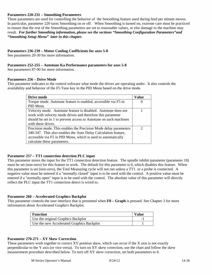
M-Series Operator’s Manual 8/24/12 14-36
Parameters 220-231 – Smoothing Parameters These parameters are used for controlling the behavior of the Smoothing feature used during feed per minute moves. In particular, parameter 220 turns Smoothing on or off. When Smoothing is turned on, extreme care must be practiced to ensure that the rest of the Smoothing parameters are set to reasonable values, or else damage to the machine may result. For further Smoothing information, please see the sections “Smoothing Configuration Parameters”and “Smoothing Setup Menu” later in this chapter.
Parameters 236-239 – Motor Cooling Coefficients for axes 5-8 See parameters 20-30 for more information.
Parameters 252-255 – Autotune Ka Performance parameters for axes 5-8 See parameters 87-90 for more information.
Parameters 256 – Drive Mode This parameter indicates to the control software what mode the drives are operating under. It also controls the availability and behavior of the F5 Tune key in the PID Menu based on the drive mode.
Drive mode Value Torque mode. Autotune feature is enabled, accessible via F5 in PID Menu
0
Velocity mode. Autotune feature is disabled. Autotune does not work with velocity mode drives and therefore this parameter should be set to 1 to prevent access to Autotune on such machines with these drives.
1
Precision mode. This enables the Precision Mode delay parameters 340-347. This also enables the Auto Delay Calculation feature, accessible via F5 in PID Menu, which is used to automatically calculate these parameters.
2
Parameter 257 – TT1 connection detection PLC input This parameter stores the input for the TT1 connection detection feature. The spindle inhibit parameter (parameter 18) must be set (non-zero) for this feature to work. The default for this parameter is 0, which disables this feature. When this parameter is set (non-zero), the Tool Measuring cycle will not run unless a TT1 or a probe is connected. A negative value must be entered if a "normally closed" input is to be used with the control. A positive value must be entered if a "normally open" input is to be used with the control. The absolute value of this parameter will directly reflect the PLC input the TT1 connection detect is wired to.
Parameter 260 – Accelerated Graphics Backplot This parameter controls the user interface that is presented when F8 – Graph is pressed. See Chapter 3 for more information about Accelerated Graphics Backplot.
Function Value Use the original Graphics Backplot -1 Use the new Accelerated Graphics Backplot 1
Parameter 270-271 – XY Skew Correction These parameters work together to correct XY position skew, which can occur if the X axis is not exactly perpendicular to the Y axis (or vice versa). To turn on XY skew correction, use the chart and follow the skew measurement procedure described below. To turn off XY skew correction, set both parameters to 0.
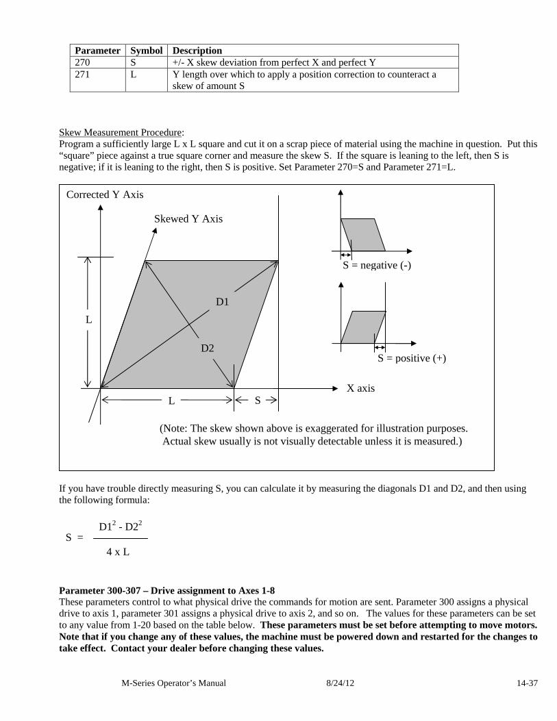
M-Series Operator’s Manual 8/24/12 14-37
Parameter Symbol Description 270 S +/- X skew deviation from perfect X and perfect Y 271 L Y length over which to apply a position correction to counteract a
skew of amount S Skew Measurement Procedure: Program a sufficiently large L x L square and cut it on a scrap piece of material using the machine in question. Put this “square” piece against a true square corner and measure the skew S. If the square is leaning to the left, then S is negative; if it is leaning to the right, then S is positive. Set Parameter 270=S and Parameter 271=L.
If you have trouble directly measuring S, you can calculate it by measuring the diagonals D1 and D2, and then using the following formula:
Parameter 300-307 – Drive assignment to Axes 1-8 These parameters control to what physical drive the commands for motion are sent. Parameter 300 assigns a physical drive to axis 1, parameter 301 assigns a physical drive to axis 2, and so on. The values for these parameters can be set to any value from 1-20 based on the table below. These parameters must be set before attempting to move motors. Note that if you change any of these values, the machine must be powered down and restarted for the changes to take effect. Contact your dealer before changing these values.
Skewed Y Axis
D1
D2
Corrected Y Axis
L S
S = positive (+)
S = negative (-)
X axis
L
(Note: The skew shown above is exaggerated for illustration purposes. Actual skew usually is not visually detectable unless it is measured.)
S = 4 x L
D12 - D22
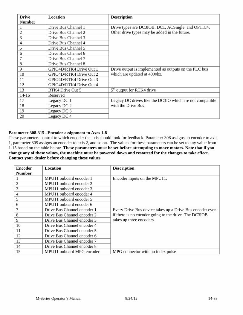
M-Series Operator’s Manual 8/24/12 14-38
Drive Number
Location Description
1 Drive Bus Channel 1 2 Drive Bus Channel 2 3 Drive Bus Channel 3 4 Drive Bus Channel 4 5 Drive Bus Channel 5 6 Drive Bus Channel 6 7 Drive Bus Channel 7 8 Drive Bus Channel 8
Drive types are DC3IOB, DC1, ACSingle, and OPTIC4. Other drive types may be added in the future.
9 GPIO4D/RTK4 Drive Out 1 10 GPIO4D/RTK4 Drive Out 2 11 GPIO4D/RTK4 Drive Out 3 12 GPIO4D/RTK4 Drive Out 4
Drive output is implemented as outputs on the PLC bus which are updated at 4000hz.
13 RTK4 Drive Out 5 5th output for RTK4 drive 14-16 Reserved 17 Legacy DC 1 18 Legacy DC 2 19 Legacy DC 3 20 Legacy DC 4
Legacy DC drives like the DC3IO which are not compatible with the Drive Bus
Parameter 308-315 –Encoder assignment to Axes 1-8 These parameters control to which encoder the axis should look for feedback. Parameter 308 assigns an encoder to axis 1, parameter 309 assigns an encoder to axis 2, and so on. The values for these parameters can be set to any value from 1-15 based on the table below. These parameters must be set before attempting to move motors. Note that if you change any of these values, the machine must be powered down and restarted for the changes to take effect. Contact your dealer before changing these values.
Encoder Number
Location Description
1 MPU11 onboard encoder 1 2 MPU11 onboard encoder 2 3 MPU11 onboard encoder 3 4 MPU11 onboard encoder 4 5 MPU11 onboard encoder 5 6 MPU11 onboard encoder 6
Encoder inputs on the MPU11.
7 Drive Bus Channel encoder 1 8 Drive Bus Channel encoder 2 9 Drive Bus Channel encoder 3 10 Drive Bus Channel encoder 4 11 Drive Bus Channel encoder 5 12 Drive Bus Channel encoder 6 13 Drive Bus Channel encoder 7 14 Drive Bus Channel encoder 8
Every Drive Bus device takes up a Drive Bus encoder even if there is no encoder going to the drive. The DC3IOB takes up three encoders.
15 MPU11 onboard MPG encoder MPG connector with no index pulse
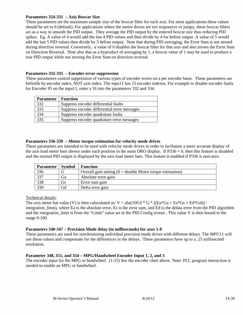
M-Series Operator’s Manual 8/24/12 14-39
Parameters 324-331 – Axis Boxcar Size These parameters set the maximum sample size of the boxcar filter for each axis. For most applications these values should be set to 0 (default). For applications where the motor drives are too responsive or jumpy, these boxcar filters act as a way to smooth the PID output. They average the PID output by the entered boxcar size thus reducing PID spikes. Eg. A value of 4 would add the last 4 PID values and then divide by 4 for before output. A value of 5 would add the last 5 PID values then divide by 5 before output. Note that during PID averaging, the Error Sum is not zeroed during direction reversal. Conversely, a value of 0 disables the boxcar filter for that axis and also zeroes the Error Sum on Direction Reversal. Note also that as a byproduct of averaging by 1, a boxcar value of 1 may be used to produce a true PID output while not zeroing the Error Sum on direction reversal.
Parameters 332-335 – Encoder error suppression These parameters control suppression of various types of encoder errors on a per encoder basis. These parameters are bitfields by encoder index, NOT axis index. The mpu11 has 15 encoder indexes. For example to disable encoder faults for Encoder #5 on the mpu11, enter a 16 into the parameters 332 and 334.
Parameter Function 332 Suppress encoder differential faults 333 Suppress encoder differential error messages 334 Suppress encoder quadrature faults 335 Suppress encoder quadrature error messages
Parameters 336-339 – Motor torque estimation for velocity mode drives These parameters are intended to be used with velocity mode drives in order to faciliatate a more accurate display of the axis load meter bars shown under each position in the main DRO display. If P336 = 0, then this feature is disabled and the normal PID output is displayed by the axis load meter bars. This feature is enabled if P336 is non-zero.
Parameter Symbol Function 336 G Overall gain setting (0 = disable Motor torque estimation) 337 Ga Absolute error gain 338 Gs Error sum gain 339 Gd Delta error gain
Technical details: The axis meter bar value (V) is then caluculated as: V = abs(100.0 * G * ((Ea*Ga + Es*Gs + Ed*Gd)) / integration_limit), where Ea is the absolute error, Es is the error sum, and Ed is the delata error from the PID algorithm and the integration_limit is from the “Limit” value set in the PID Config screen . This value V is then bound to the range 0-100.
Parameters 340-347 – Precision Mode delay (in milliseconds) for axes 1-8 These parameters are used for synchronizing individual precision mode drives with different delays. The MPU11 will use these values and compensate for the differences in the delays. These parameters have up to a .25 millisecond resolution.
Parameter 348, 351, and 354 – MPG/Handwheel Encoder Input 1, 2, and 3 The encoder input for the MPG or handwheel. (1-15) See the encoder chart above. Note: PLC program interaction is needed to enable an MPG or handwheel.
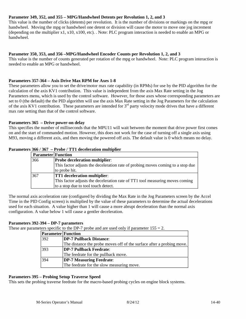
M-Series Operator’s Manual 8/24/12 14-40
Parameter 349, 352, and 355 – MPG/Handwheel Detents per Revolution 1, 2, and 3 This value is the number of clicks (detents) per revolution. It is the number of divisions or markings on the mpg or handwheel. Moving the mpg or handwheel one detent or division will cause the motor to move one jog increment (depending on the multiplier x1, x10, x100, etc). . Note: PLC program interaction is needed to enable an MPG or handwheel.
Parameter 350, 353, and 356 –MPG/Handwheel Encoder Counts per Revolution 1, 2, and 3 This value is the number of counts generated per rotation of the mpg or handwheel. Note: PLC program interaction is needed to enable an MPG or handwheel.
Parameters 357-364 – Axis Drive Max RPM for Axes 1-8 These parameters allow you to set the drive/motor max rate capability (in RPMs) for use by the PID algorithm for the calculation of the axis KV1 contribution. This value is independent from the axis Max Rate setting in the Jog Parameters menu, which is used by the control software. However, for those axes whose corresponding parameters are set to 0 (the default) the the PID algorithm will use the axis Max Rate setting in the Jog Parameters for the calculation of the axis KV1 contribution. These parameters are intended for 3rd party velocity mode drives that have a different max rate setting than that of the control software.
Parameters 365 – Drive power-on delay This specifies the number of milliseconds that the MPU11 will wait between the moment that drive power first comes on and the start of commanded motion. However, this does not work for the case of turning off a single axis using M93, moving a different axis, and then moving the powered off axis. The default value is 0 which means no delay.
Parameters 366 / 367 – Probe / TT1 deceleration multiplier Parameter Function 366 Probe deceleration multiplier:
This factor adjusts the deceleration rate of probing moves coming to a stop due to probe hit.
367 TT1 deceleration multiplier: This factor adjusts the deceleration rate of TT1 tool measuring moves coming to a stop due to tool touch detect.
The normal axis acceleration rate (configured by dividing the Max Rate in the Jog Parameters screen by the Accel Time in the PID Config screen) is multiplied by the value of these parameters to determine the actual decelerations used for each situation. A value higher than 1 will cause a more abrupt deceleration than the normal axis configuration. A value below 1 will cause a gentler deceleration.
Parameters 392-394 – DP-7 parameters These are parameters specific to the DP-7 probe and are used only if parameter 155 = 2.
Parameter Function 392 DP-7 Pullback Distance:
The distance the probe moves off of the surface after a probing move. 393 DP-7 Pullback Feedrate:
The feedrate for the pullback move. 394 DP-7 Measuring Feedrate:
The feedrate for the slow measuring move.
Parameters 395 – Probing Setup Traverse Speed This sets the probing traverse feedrate for the macro-based probing cycles on engine block systems.

M-Series Operator’s Manual 8/24/12 14-41
Parameters 396 – Probing Setup Plunge Speed This sets the probing plunge feedrate for the macro-based probing cycles on engine block systems.
Parameters 398 – Port/Block mode This determines the current mode of Port/Block systems and is set by the Port/Block menu. This parameter should not be manually modified.
Value Mode 0 3-Axis 1 Engine Block 2 Tilt Table
.
Parameters 399 – AD1 arc chord tolerance adjustment This parameter adjusts the precision of AD1 arcs. When Smoothing is turned off (P220 = 0) arc moves (such as G2 and G3) are generated as a string of many small linear moves that are used to closely approximate the programmed arc. These small linear moves are called arc chords. These arc chords straddle each side of the theoretical true arc path, but their distance (in encoder counts) from the path is limited by what value is set in this parameter. The default value is .5, meaning that by default the arc chord never strays away from theoretical true arc by more than ½ encoder count.
Parameters 900-999 – PLC program parameters These parameters are used as a way of communicating floating point values to a PLC program. The meanings of these parameters depends on how a PLC program uses them and can vary from one machine to another. One suggested use of these parameters is as a set of configuration values. The values of these parameters are saved upon modification (via a menu or CNC job) and will be retain their values even after shutdown and restart of the control software. All remaining parameters are reserved for further expansion.
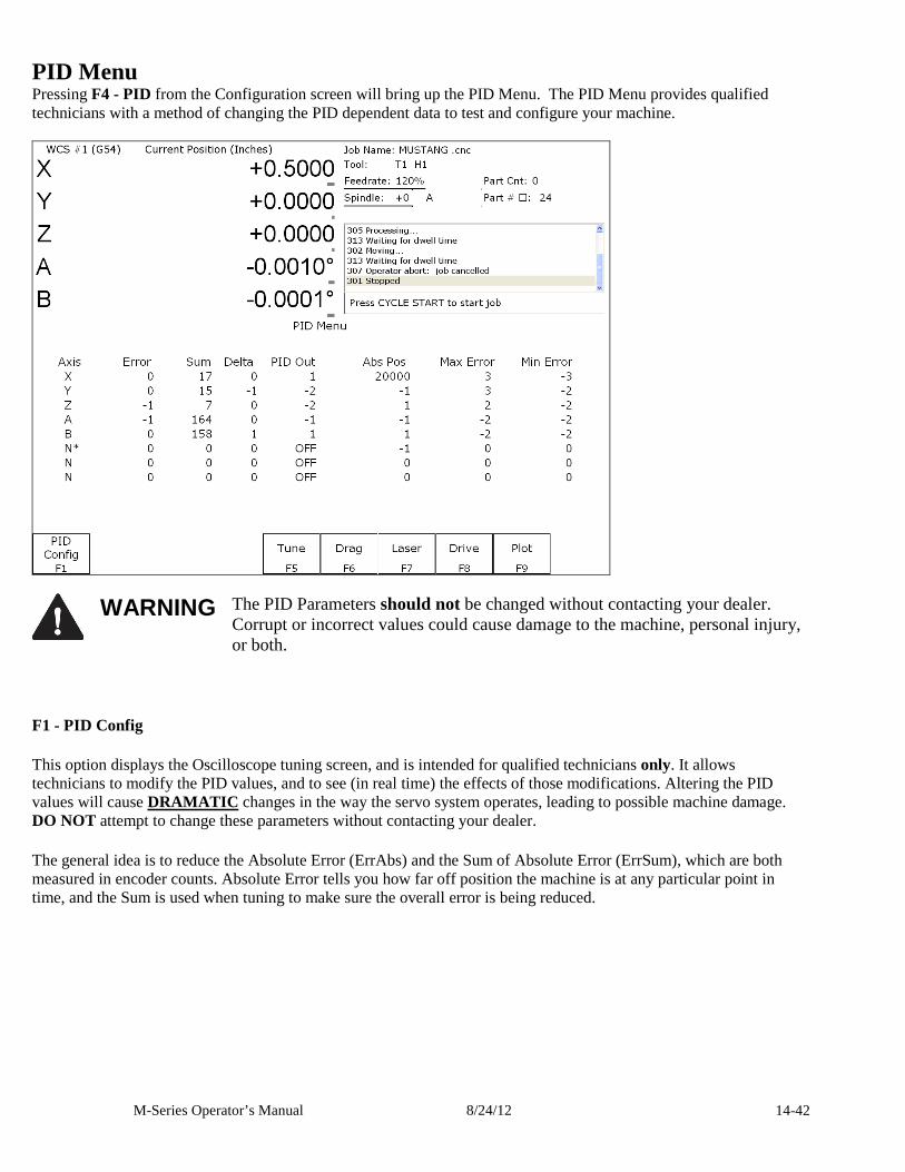
M-Series Operator’s Manual 8/24/12 14-42
PID Menu Pressing F4 - PID from the Configuration screen will bring up the PID Menu. The PID Menu provides qualified technicians with a method of changing the PID dependent data to test and configure your machine.
WARNING The PID Parameters should not be changed without contacting your dealer.
Corrupt or incorrect values could cause damage to the machine, personal injury, or both.
F1 - PID Config
This option displays the Oscilloscope tuning screen, and is intended for qualified technicians only. It allows technicians to modify the PID values, and to see (in real time) the effects of those modifications. Altering the PID values will cause DRAMATIC changes in the way the servo system operates, leading to possible machine damage. DO NOT attempt to change these parameters without contacting your dealer.
The general idea is to reduce the Absolute Error (ErrAbs) and the Sum of Absolute Error (ErrSum), which are both measured in encoder counts. Absolute Error tells you how far off position the machine is at any particular point in time, and the Sum is used when tuning to make sure the overall error is being reduced.
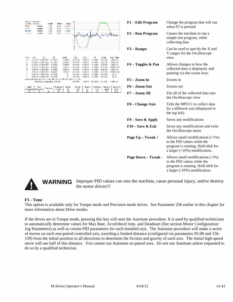
M-Series Operator’s Manual 8/24/12 14-43
F1 – Edit Program Change the program that will run
when F2 is pressed
F2 – Run Program Causes the machine to run a simple test program, while collecting data
F3 – Ranges Can be used to specify the X and Y ranges for the Oscilloscope view
F4 – Toggles & Pan Allows changes to how the collected data is displayed, and panning via the cursor keys
F5 – Zoom In Zooms in
F6 – Zoom Out Zooms out
F7 – Zoom All Fits all of the collected data into the Oscilloscope view
F8 – Change Axis Tells the MPU11 to collect data for a different axis (displayed in the top left)
F9 – Save & Apply Saves any modifications
F10 – Save & Exit Saves any modifications and exits the Oscilloscope menu
Page Up – Tweak + Allows small modifications (+1%) to the PID values while the program is running. Hold shift for a larger (+10%) modification.
Page Down – Tweak - Allows small modifications (-1%) to the PID values while the program is running. Hold shift for a larger (-10%) modification.
WARNING Improper PID values can ruin the machine, cause personal injury, and/or destroy
the motor drives!!!
F5 - Tune This option is available only for Torque mode and Precision mode drives. See Parameter 256 earlier in this chapter for more information about Drive modes. If the drives are in Torque mode, pressing this key will start the Autotune procedure. It is used by qualified technicians to automatically determine values for Max Rate, Accel/decel time, and Deadstart (See section Motor Configuration: Jog Parameters) as well as certain PID parameters for each installed axis. The Autotune procedure will make a series of moves on each non-paired controlled axis, traveling a limited distance (configured via parameters 95-98 and 156-159) from the initial position in all directions to determine the friction and gravity of each axis. The initial high-speed move will use half of this distance. You cannot run Autotune on paired axes. Do not run Autotune unless requested to do so by a qualified technician.
M-Series Operator’s Manual 8/24/12 14-44
If the drives are in Precision mode, pressing this key will start the Auto Delay Calculation procedure. It is used by qualified technicians to automatically determine values for the Precision Mode delay parameters 340-347. The Auto Delay Calculation procedure will make a single move on each non-paired controlled axis, traveling a limited distance (configured via parameters 95-98 and 156-159) from the initial position. You cannot run the Auto Delay Calculation procedure on paired axes. Do not run the Auto Delay Calculation procedure unless requested to do so by a qualified technician.
F6 - Drag This option is used by qualified technicians to determine whether your machine is binding anywhere along the axis travel. To run a drag test press F6 - Drag to begin the drag test. Press F1 - Next Axis to select the axis you wish to check and then hit the CYCLE START button. A text file drag_x.out, or a similarly named file is generated and stored in the c:\cncm directory. If significant drag occurs, a message will be displayed on-screen. Contact your dealer to correct the problem as soon as possible.
F7 - Laser This option is used by qualified technicians to take automated laser measurements and create or adjust the ballscrew compensation tables. Do not attempt to run automatic laser compensation without first contacting your dealer for details.
F8 - Drive This menu will only appear on AC systems and only affects using SD or ACSingle drives. It is not for general viewing and definitely not for modification by any unqualified individual. For more information about this menu option, refer to the SD installation manual.
F9 - Plot This option is used by qualified technicians to plot data.
Test This menu only appears if the system has not yet been configured and initialized or if a new solid state disk has been installed. For more information, please contact your dealer.
ATC Init. This menu will only appear on enhanced ATC systems. Please see your ATC manual for further information.
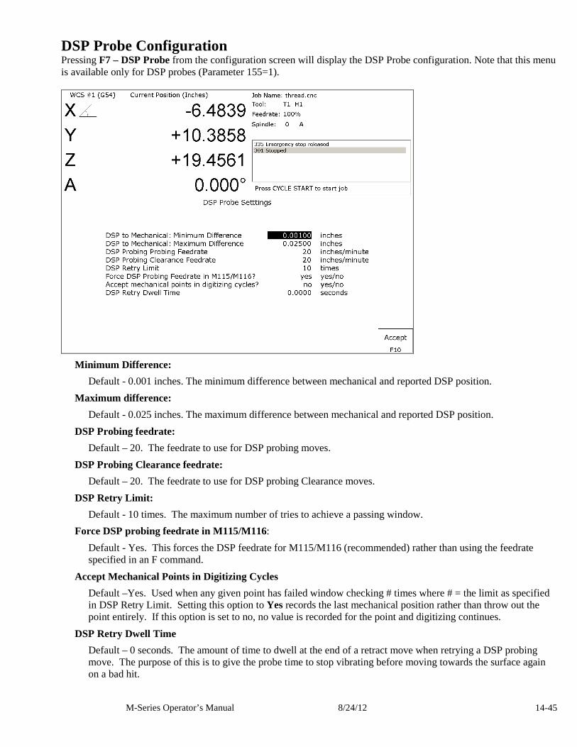
M-Series Operator’s Manual 8/24/12 14-45
DSP Probe Configuration Pressing F7 – DSP Probe from the configuration screen will display the DSP Probe configuration. Note that this menu is available only for DSP probes (Parameter 155=1).
Minimum Difference:
Default - 0.001 inches. The minimum difference between mechanical and reported DSP position.
Maximum difference:
Default - 0.025 inches. The maximum difference between mechanical and reported DSP position.
DSP Probing feedrate:
Default – 20. The feedrate to use for DSP probing moves.
DSP Probing Clearance feedrate:
Default – 20. The feedrate to use for DSP probing Clearance moves.
DSP Retry Limit:
Default - 10 times. The maximum number of tries to achieve a passing window.
Force DSP probing feedrate in M115/M116:
Default - Yes. This forces the DSP feedrate for M115/M116 (recommended) rather than using the feedrate specified in an F command.
Accept Mechanical Points in Digitizing Cycles
Default –Yes. Used when any given point has failed window checking # times where # = the limit as specified in DSP Retry Limit. Setting this option to Yes records the last mechanical position rather than throw out the point entirely. If this option is set to no, no value is recorded for the point and digitizing continues.
DSP Retry Dwell Time
Default – 0 seconds. The amount of time to dwell at the end of a retract move when retrying a DSP probing move. The purpose of this is to give the probe time to stop vibrating before moving towards the surface again on a bad hit.
M-Series Operator’s Manual 8/24/12 14-46
Other DSP Probe settings
The DSP Probe eliminates the need for a multiple-hit probe measuring move (A fast inward move to find the surface followed by a slow move to measure the surface). Therefore, the Slow Probing Rate (parameter 15) does not apply to probing moves when the DSP probe is enabled. However, the Slow Probing Rate still applies to TT1 tool measurements. The Fast Probing Rate (parameter 14) is still used for positioning moves in digitizing cycles, but not for probing mvoes which measure the surface. Instead, the DSP Probing feedrate is used for these moves.
The following list is a list of other parameters which affect the DSP Probe. See the parameter descriptions in the Machine Parameters section (earlier in this chapter) for more information.
Probe Type (Parameter 155):
This parameter enables/disables the DSP Probe.
Recovery Distance (Parameter 13):
This parameter is used for failed DSP windows. On a failed window, the DSP probe will retract this distance before retrying.
Fast Probing Rate (Parameter 14):
Used for positioning moves in digitizing and probing routines. These are moves which are not measuring a surface. It is not used for surface measuring moves when the DSP probe is enabled.
Slow Probing Rate (Parameter 15):
Not used by the DSP probe. However, it will still be used by TT-1 tool measurements.
Repeatability Tolerance (Parameter 151):
Recommended value is 0 (disabled). This parameter enables repeatability checking. It will work in conjunction with the DSP probe.
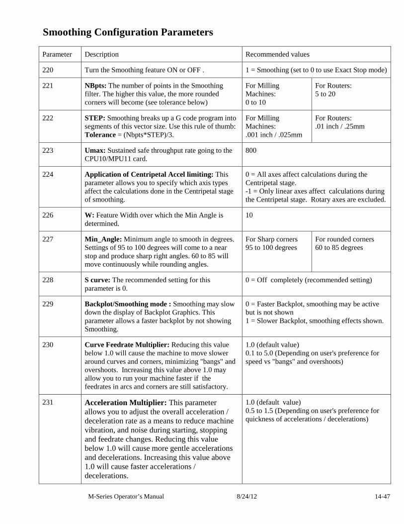
M-Series Operator’s Manual 8/24/12 14-47
Smoothing Configuration Parameters
Parameter Description Recommended values
220 Turn the Smoothing feature ON or OFF . 1 = Smoothing (set to 0 to use Exact Stop mode)
221 NBpts: The number of points in the Smoothing filter. The higher this value, the more rounded corners will become (see tolerance below)
For Milling Machines: 0 to 10
For Routers: 5 to 20
222 STEP: Smoothing breaks up a G code program into segments of this vector size. Use this rule of thumb: Tolerance = (Nbpts*STEP)/3.
For Milling Machines: .001 inch / .025mm
For Routers: .01 inch / .25mm
223 Umax: Sustained safe throughput rate going to the CPU10/MPU11 card.
800
224 Application of Centripetal Accel limiting: This parameter allows you to specify which axis types affect the calculations done in the Centripetal stage of smoothing.
0 = All axes affect calculations during the Centripetal stage. -1 = Only linear axes affect calculations during the Centripetal stage. Rotary axes are excluded.
226 W: Feature Width over which the Min Angle is determined.
10
227 Min_Angle: Minimum angle to smooth in degrees. Settings of 95 to 100 degrees will come to a near stop and produce sharp right angles. 60 to 85 will move continuously while rounding angles.
For Sharp corners 95 to 100 degrees
For rounded corners 60 to 85 degrees
228 S curve: The recommended setting for this parameter is 0.
0 = Off completely (recommended setting)
229 Backplot/Smoothing mode : Smoothing may slow down the display of Backplot Graphics. This parameter allows a faster backplot by not showing Smoothing.
0 = Faster Backplot, smoothing may be active but is not shown 1 = Slower Backplot, smoothing effects shown.
230 Curve Feedrate Multiplier: Reducing this value below 1.0 will cause the machine to move slower around curves and corners, minimizing "bangs" and overshoots. Increasing this value above 1.0 may allow you to run your machine faster if the feedrates in arcs and corners are still satisfactory.
1.0 (default value) 0.1 to 5.0 (Depending on user's preference for speed vs "bangs" and overshoots)
231 Acceleration Multiplier: This parameter allows you to adjust the overall acceleration / deceleration rate as a means to reduce machine vibration, and noise during starting, stopping and feedrate changes. Reducing this value below 1.0 will cause more gentle accelerations and decelerations. Increasing this value above 1.0 will cause faster accelerations / decelerations.
1.0 (default value) 0.5 to 1.5 (Depending on user's preference for quickness of accelerations / decelerations)
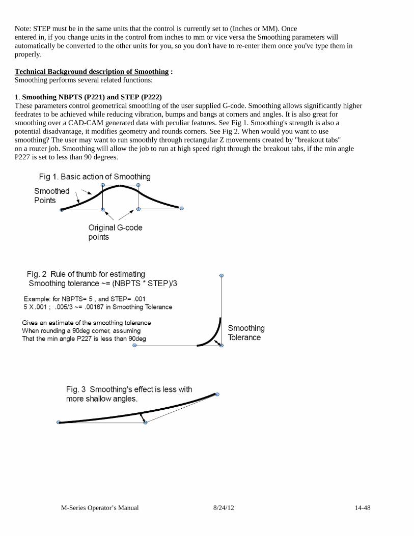
M-Series Operator’s Manual 8/24/12 14-48
Note: STEP must be in the same units that the control is currently set to (Inches or MM). Once entered in, if you change units in the control from inches to mm or vice versa the Smoothing parameters will automatically be converted to the other units for you, so you don't have to re-enter them once you've type them in properly. Technical Background description of Smoothing : Smoothing performs several related functions: 1. Smoothing NBPTS (P221) and STEP (P222) These parameters control geometrical smoothing of the user supplied G-code. Smoothing allows significantly higher feedrates to be achieved while reducing vibration, bumps and bangs at corners and angles. It is also great for smoothing over a CAD-CAM generated data with peculiar features. See Fig 1. Smoothing's strength is also a potential disadvantage, it modifies geometry and rounds corners. See Fig 2. When would you want to use smoothing? The user may want to run smoothly through rectangular Z movements created by "breakout tabs" on a router job. Smoothing will allow the job to run at high speed right through the breakout tabs, if the min angle P227 is set to less than 90 degrees.
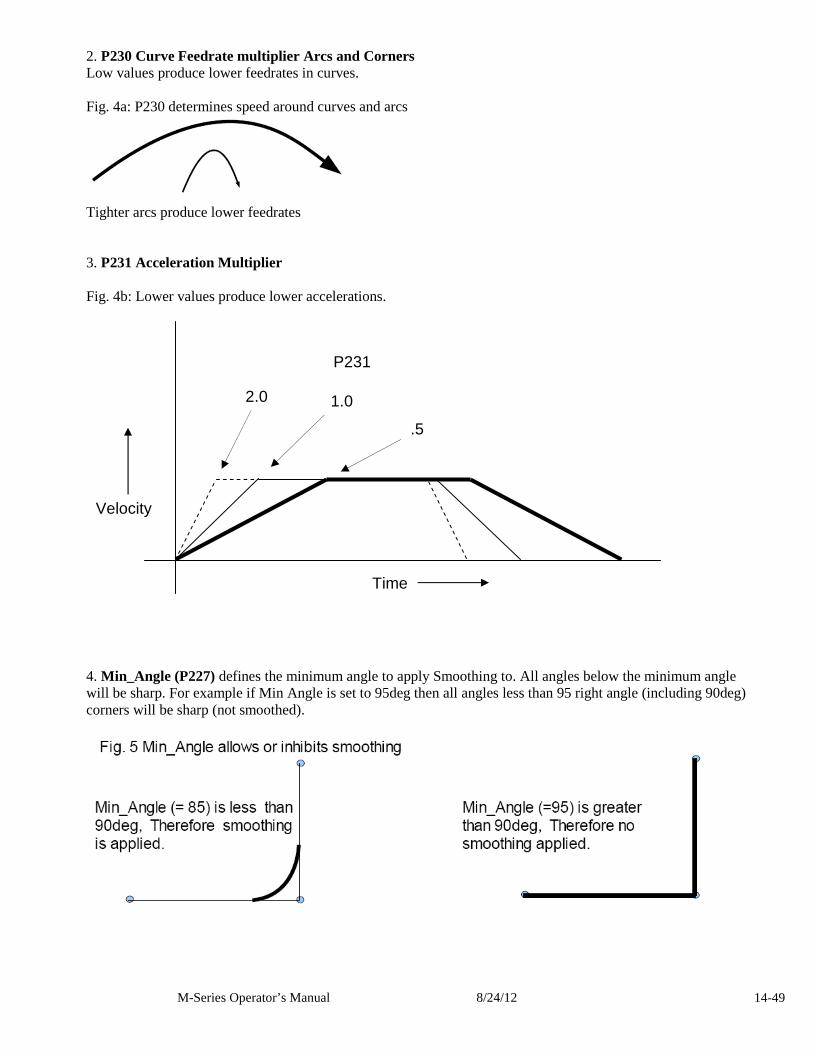
M-Series Operator’s Manual 8/24/12 14-49
2. P230 Curve Feedrate multiplier Arcs and Corners Low values produce lower feedrates in curves. Fig. 4a: P230 determines speed around curves and arcs
Tighter arcs produce lower feedrates 3. P231 Acceleration Multiplier Fig. 4b: Lower values produce lower accelerations.
4. Min_Angle (P227) defines the minimum angle to apply Smoothing to. All angles below the minimum angle will be sharp. For example if Min Angle is set to 95deg then all angles less than 95 right angle (including 90deg) corners will be sharp (not smoothed).
Velocity
Time
2.0 1.0
.5
P231
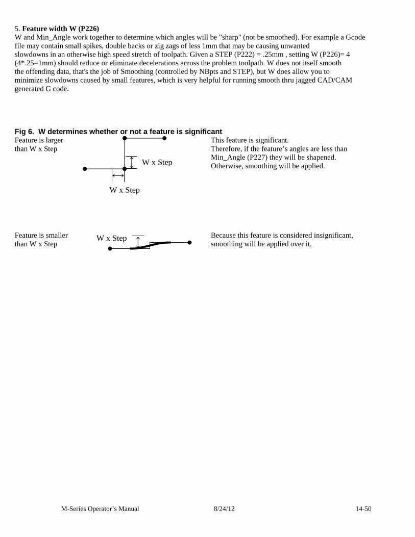
M-Series Operator’s Manual 8/24/12 14-50
5. Feature width W (P226) W and Min_Angle work together to determine which angles will be "sharp" (not be smoothed). For example a Gcode file may contain small spikes, double backs or zig zags of less 1mm that may be causing unwanted slowdowns in an otherwise high speed stretch of toolpath. Given a STEP (P222) = .25mm , setting W (P226)= 4 (4*.25=1mm) should reduce or eliminate decelerations across the problem toolpath. W does not itself smooth the offending data, that's the job of Smoothing (controlled by NBpts and STEP), but W does allow you to minimize slowdowns caused by small features, which is very helpful for running smooth thru jagged CAD/CAM generated G code. Fig 6. W determines whether or not a feature is si gnificant Feature is larger than W x Step
This feature is significant. Therefore, if the feature’s angles are less than Min_Angle (P227) they will be shapened. Otherwise, smoothing will be applied.
Feature is smaller than W x Step
Because this feature is considered insignificant, smoothing will be applied over it.
W x Step
W x Step
W x Step
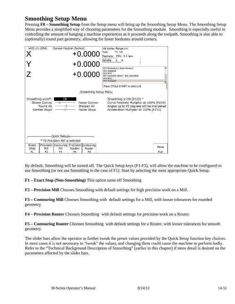
M-Series Operator’s Manual 8/24/12 14-51
Smoothing Setup Menu Pressing F8 – Smoothing Setup from the Setup menu will bring up the Smoothing Setup Menu. The Smoothing Setup Menu provides a simplified way of choosing parameters for the Smoothing module. Smoothing is especially useful in controlling the amount of banging a machine experiences as it proceeds along the toolpath. Smoothing is also able to (optionally) round part geometry, allowing for faster feedrates around corners.
By default, Smoothing will be turned off. The Quick Setup keys (F1-F5), will allow the machine to be configured to use Smoothing (or not use Smoothing in the case of F1). Start by selecting the most appropriate Quick Setup. F1 – Exact Stop (Non-Smoothing) This option turns off Smoothing F2 – Precision Mill Chooses Smoothing with default settings for high precision work on a Mill. F3 – Contouring Mill Chooses Smoothing with default settings for a Mill, with looser tolerances for rounded geometry. F4 – Precision Router Chooses Smoothing with default settings for precision work on a Router. F5 – Contouring Router Chooses Smoothing with default settings for a Router, with looser tolerances for smooth geometry. The slider bars allow the operator to further tweak the preset values provided by the Quick Setup function key choices. In most cases it is not necessary to "tweak" the values, and changing them could cause the machine to perform badly. Refer to the “Technical Background Description of Smoothing” (earlier in this chapter) if more detail is desired on the parameters affected by the slider bars.

M-Series Operator’s Manual 8/24/12 14-52
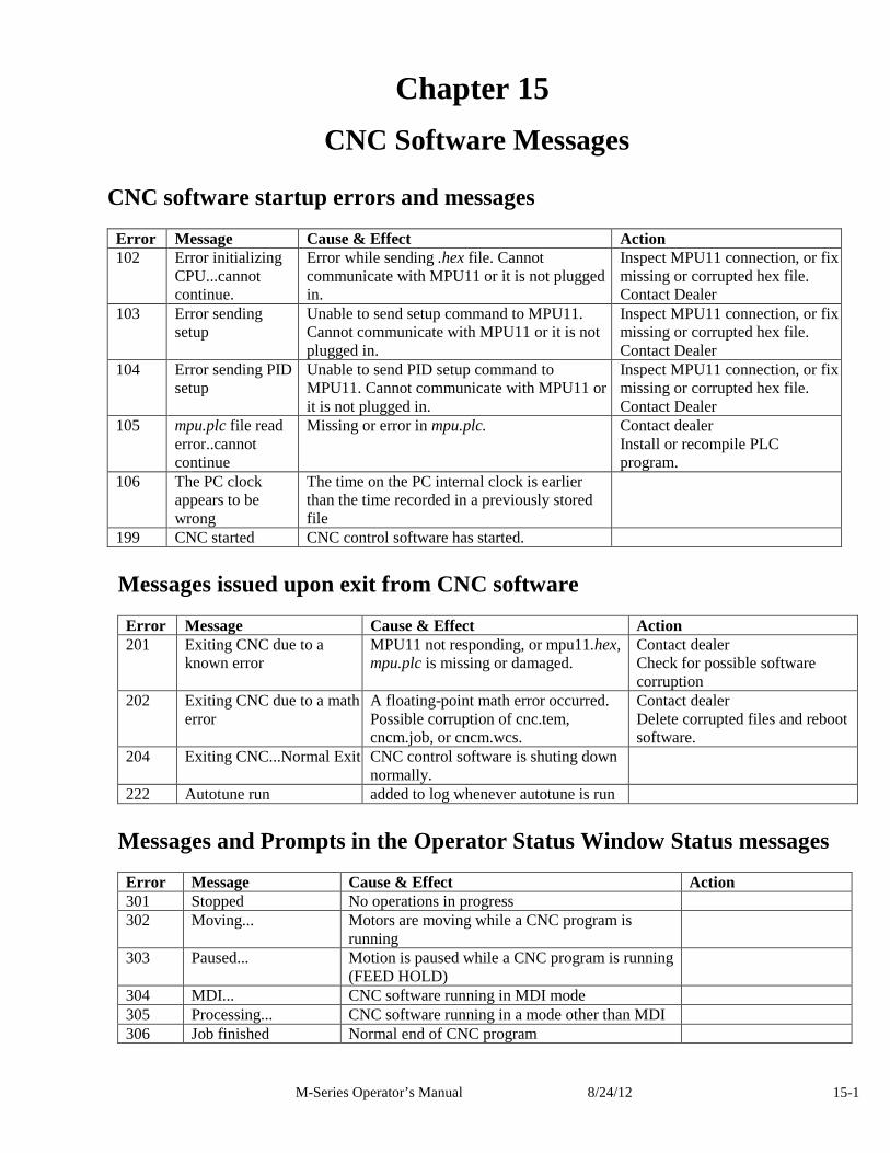
M-Series Operator’s Manual 8/24/12 15-1
Chapter 15
CNC Software Messages
CNC software startup errors and messages
Error Message Cause & Effect Action 102 Error initializing
CPU...cannot continue.
Error while sending .hex file. Cannot communicate with MPU11 or it is not plugged in.
Inspect MPU11 connection, or fix missing or corrupted hex file. Contact Dealer
103 Error sending setup
Unable to send setup command to MPU11. Cannot communicate with MPU11 or it is not plugged in.
Inspect MPU11 connection, or fix missing or corrupted hex file. Contact Dealer
104 Error sending PID setup
Unable to send PID setup command to MPU11. Cannot communicate with MPU11 or it is not plugged in.
Inspect MPU11 connection, or fix missing or corrupted hex file. Contact Dealer
105 mpu.plc file read error..cannot continue
Missing or error in mpu.plc. Contact dealer Install or recompile PLC program.
106 The PC clock appears to be wrong
The time on the PC internal clock is earlier than the time recorded in a previously stored file
199 CNC started CNC control software has started.
Messages issued upon exit from CNC software
Error Message Cause & Effect Action 201 Exiting CNC due to a
known error
MPU11 not responding, or mpu11.hex, mpu.plc is missing or damaged.
Contact dealer Check for possible software corruption
202 Exiting CNC due to a math error
A floating-point math error occurred. Possible corruption of cnc.tem, cncm.job, or cncm.wcs.
Contact dealer Delete corrupted files and reboot software.
204 Exiting CNC...Normal Exit CNC control software is shuting down normally.
222 Autotune run added to log whenever autotune is run
Messages and Prompts in the Operator Status Window Status messages
Error Message Cause & Effect Action 301 Stopped No operations in progress 302 Moving... Motors are moving while a CNC program is
running
303 Paused... Motion is paused while a CNC program is running (FEED HOLD)
304 MDI... CNC software running in MDI mode 305 Processing... CNC software running in a mode other than MDI 306 Job finished Normal end of CNC program
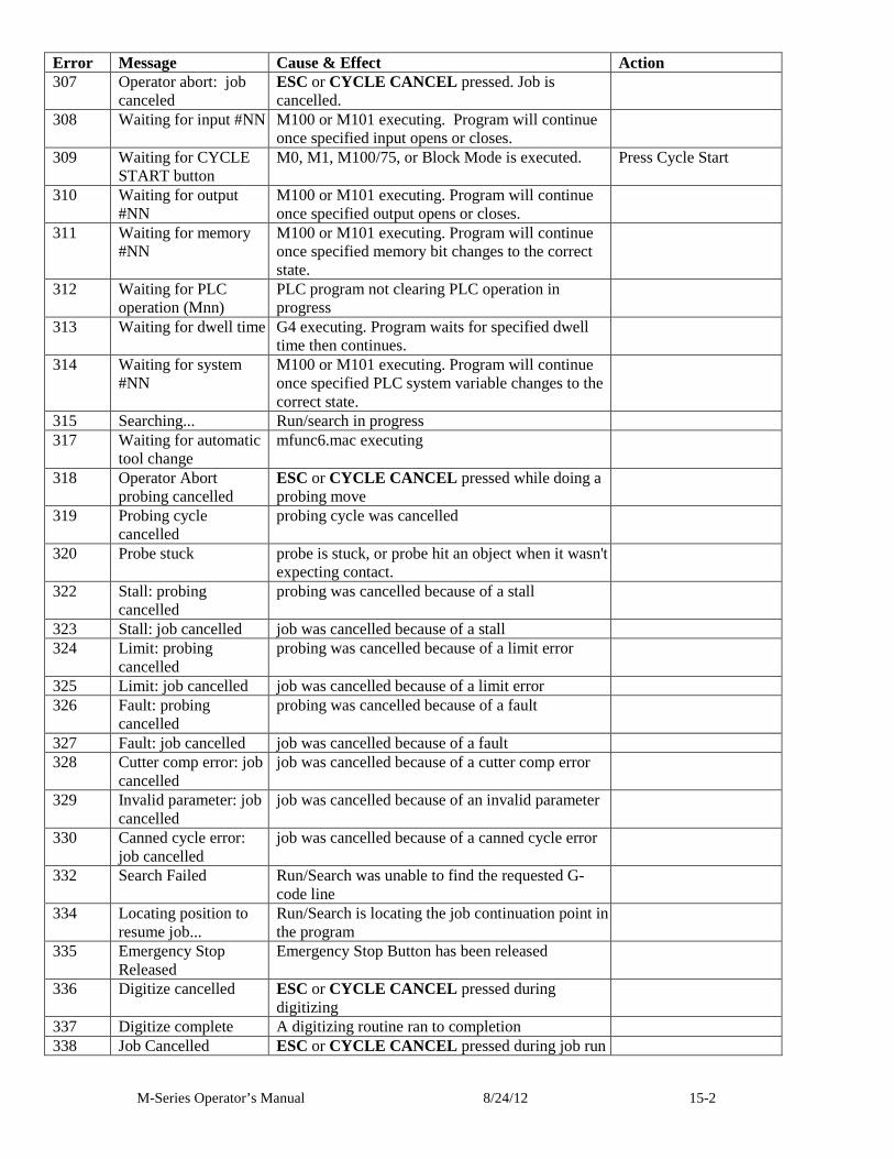
M-Series Operator’s Manual 8/24/12 15-2
Error Message Cause & Effect Action 307 Operator abort: job
canceled ESC or CYCLE CANCEL pressed. Job is cancelled.
308 Waiting for input #NN M100 or M101 executing. Program will continue once specified input opens or closes.
309 Waiting for CYCLE START button
M0, M1, M100/75, or Block Mode is executed. Press Cycle Start
310 Waiting for output #NN
M100 or M101 executing. Program will continue once specified output opens or closes.
311 Waiting for memory #NN
M100 or M101 executing. Program will continue once specified memory bit changes to the correct state.
312 Waiting for PLC operation (Mnn)
PLC program not clearing PLC operation in progress
313 Waiting for dwell time G4 executing. Program waits for specified dwell time then continues.
314 Waiting for system #NN
M100 or M101 executing. Program will continue once specified PLC system variable changes to the correct state.
315 Searching... Run/search in progress 317 Waiting for automatic
tool change mfunc6.mac executing
318 Operator Abort probing cancelled
ESC or CYCLE CANCEL pressed while doing a probing move
319 Probing cycle cancelled
probing cycle was cancelled
320 Probe stuck probe is stuck, or probe hit an object when it wasn't expecting contact.
322 Stall: probing cancelled
probing was cancelled because of a stall
323 Stall: job cancelled job was cancelled because of a stall 324 Limit: probing
cancelled probing was cancelled because of a limit error
325 Limit: job cancelled job was cancelled because of a limit error 326 Fault: probing
cancelled probing was cancelled because of a fault
327 Fault: job cancelled job was cancelled because of a fault 328 Cutter comp error: job
cancelled job was cancelled because of a cutter comp error
329 Invalid parameter: job cancelled
job was cancelled because of an invalid parameter
330 Canned cycle error: job cancelled
job was cancelled because of a canned cycle error
332 Search Failed Run/Search was unable to find the requested G-code line
334 Locating position to resume job...
Run/Search is locating the job continuation point in the program
335 Emergency Stop Released
Emergency Stop Button has been released
336 Digitize cancelled ESC or CYCLE CANCEL pressed during digitizing
337 Digitize complete A digitizing routine ran to completion 338 Job Cancelled ESC or CYCLE CANCEL pressed during job run
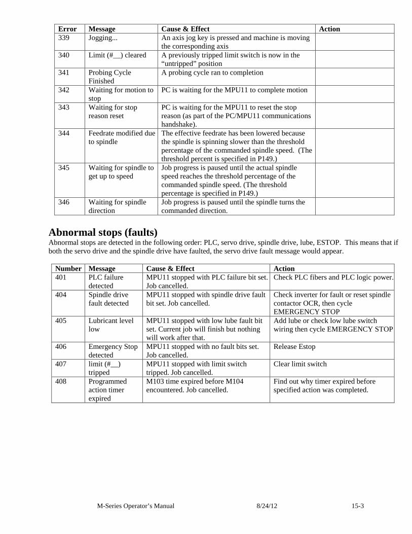
M-Series Operator’s Manual 8/24/12 15-3
Error Message Cause & Effect Action 339 Jogging... An axis jog key is pressed and machine is moving
the corresponding axis
340 Limit (#__) cleared A previously tripped limit switch is now in the “untripped” position
341 Probing Cycle Finished
A probing cycle ran to completion
342 Waiting for motion to stop
PC is waiting for the MPU11 to complete motion
343 Waiting for stop reason reset
PC is waiting for the MPU11 to reset the stop reason (as part of the PC/MPU11 communications handshake).
344 Feedrate modified due to spindle
The effective feedrate has been lowered because the spindle is spinning slower than the threshold percentage of the commanded spindle speed. (The threshold percent is specified in P149.)
345 Waiting for spindle to get up to speed
Job progress is paused until the actual spindle speed reaches the threshold percentage of the commanded spindle speed. (The threshold percentage is specified in P149.)
346 Waiting for spindle direction
Job progress is paused until the spindle turns the commanded direction.
Abnormal stops (faults) Abnormal stops are detected in the following order: PLC, servo drive, spindle drive, lube, ESTOP. This means that if both the servo drive and the spindle drive have faulted, the servo drive fault message would appear.
Number Message Cause & Effect Action 401 PLC failure
detected MPU11 stopped with PLC failure bit set. Job cancelled.
Check PLC fibers and PLC logic power.
404 Spindle drive fault detected
MPU11 stopped with spindle drive fault bit set. Job cancelled.
Check inverter for fault or reset spindle contactor OCR, then cycle EMERGENCY STOP
405 Lubricant level low
MPU11 stopped with low lube fault bit set. Current job will finish but nothing will work after that.
Add lube or check low lube switch wiring then cycle EMERGENCY STOP
406 Emergency Stop detected
MPU11 stopped with no fault bits set. Job cancelled.
Release Estop
407 limit (#__) tripped
MPU11 stopped with limit switch tripped. Job cancelled.
Clear limit switch
408 Programmed action timer expired
M103 time expired before M104 encountered. Job cancelled.
Find out why timer expired before specified action was completed.
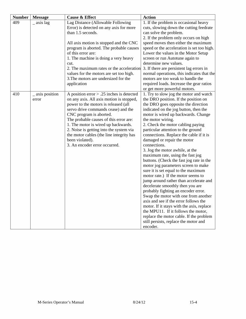
M-Series Operator’s Manual 8/24/12 15-4
Number Message Cause & Effect Action 409 _ axis lag Lag Distance (Allowable Following
Error) is detected on any axis for more than 1.5 seconds. All axis motion is stopped and the CNC program is aborted. The probable causes of this error are: 1. The machine is doing a very heavy cut. 2. The maximum rates or the acceleration values for the motors are set too high. 3.The motors are undersized for the application
1. If the problem is occasional heavy cuts, slowing down the cutting feedrate can solve the problem. 2. If the problem only occurs on high speed moves then either the maximum speed or the acceleration is set too high. Lower the values in the Motor Setup screen or run Autotune again to determine new values. 3. If there are persistent lag errors in normal operations, this indicates that the motors are too weak to handle the required loads. Increase the gear ratios or get more powerful motors.
410 _ axis position error
A position error > .25 inches is detected on any axis. All axis motion is stopped, power to the motors is released (all servo drive commands cease) and the CNC program is aborted. The probable causes of this error are: 1. The motor is wired up backwards. 2. Noise is getting into the system via the motor cables (the line integrity has been violated). 3. An encoder error occurred.
1. Try to slow jog the motor and watch the DRO position. If the position on the DRO goes opposite the direction indicated on the jog button, then the motor is wired up backwards. Change the motor wiring. 2. Check the motor cabling paying particular attention to the ground connections. Replace the cable if it is damaged or repair the motor connections. 3. Jog the motor awhile, at the maximum rate, using the fast jog buttons. (Check the fast jog rate in the motor jog parameters screen to make sure it is set equal to the maximum motor rate.) If the motor seems to jump around rather than accelerate and decelerate smoothly then you are probably fighting an encoder error. Swap the motor with one from another axis and see if the error follows the motor. If it stays with the axis, replace the MPU11. If it follows the motor, replace the motor cable. If the problem still persists, replace the motor and encoder.
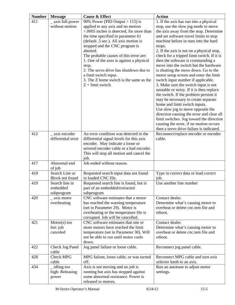
M-Series Operator’s Manual 8/24/12 15-5
Number Message Cause & Effect Action 411 _ axis full power
without motion 90% Power (PID Output > 115) is applied to any axis and no motion >.0005 inches is detected, for more than the time specified in parameter 61 (default .5 sec.). All axis motion is stopped and the CNC program is aborted. The probable causes of this error are: 1. One of the axes is against a physical stop. 2. The servo drive has shutdown due to a limit switch input. 3. The Z home switch is the same as the Z + limit switch.
1. If the axis has run into a physical stop, use the slow jog mode to move the axis away from the stop. Determine and set software travel limits to stop machine before in runs into the hard stops. 2. If the axis is not on a physical stop, check for a tripped limit switch. If it is then the software is commanding a move into the switch but the hardware is shutting the move down. Go to the motor setup screen and enter the limit switch input number if applicable. 3. Make sure the switch input is not unstable or noisy. If it is then replace the switch. If the problem persists it may be necessary to create separate home and limit switch inputs. Use slow jog to move opposite the direction causing the error and clear all limit switches. Jog toward the direction causing the error, if no motion occurs then a servo drive failure is indicated.
412 _ axis encoder differential error
An error condition was detected in the differential signal levels for this axis encoder. May indicate a loose or severed encoder cable or a bad encoder. This will stop all motion and cancel the job.
Reconnect/replace encoder or encoder cable.
417 Abnormal end of job
Job ended without reason.
418 Search Line or Block not found
Requested search input data not found in loaded CNC file.
Type in correct data or load correct job.
419 Search line in embedded subprogram
Requested search line is found, but is part of an embedded/extracted subprogram
Use another line number
420 _ axis motor overheating
CNC software estimates that a motor has reached the warning temperature (set in Parameter 29). Motor is overheating or the temperature file is corrupted. Job will be cancelled.
Contact dealer. Determine what’s causing motor to overheat or delete cnc.tem file and reboot.
421 Motor(s) too hot: job canceled
CNC software estimates that one or more motors have reached the limit temperature (set in Parameter 30). Will not be able to run until motor cools down.
Contact dealer. Determine what’s causing motor to overheat or delete cnc.tem file and reboot.
422 Check Jog Panel cable
Jog panel failure or loose cable. Reconnect jog panel cable.
428 Check MPG cable
MPG failure, loose cable, or was turned off.
Reconnect MPG cable and turn axis selector knob to an axis.
434 _ idling too high: Releasing power
Axis is not moving and no job is running but axis has stopped against some abnormal resistance. Power is released to motors.
Run an autotune to adjust motor settings.
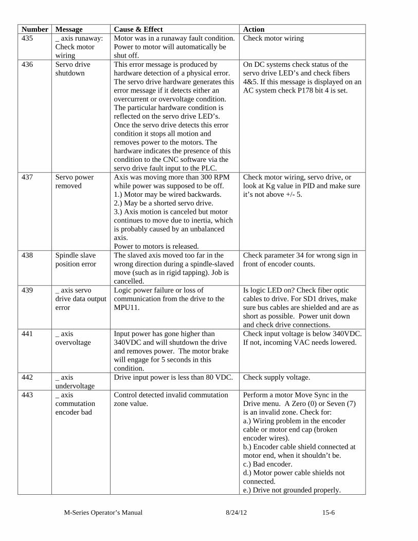
M-Series Operator’s Manual 8/24/12 15-6
Number Message Cause & Effect Action 435 _ axis runaway:
Check motor wiring
Motor was in a runaway fault condition. Power to motor will automatically be shut off.
Check motor wiring
436 Servo drive shutdown
This error message is produced by hardware detection of a physical error. The servo drive hardware generates this error message if it detects either an overcurrent or overvoltage condition. The particular hardware condition is reflected on the servo drive LED’s. Once the servo drive detects this error condition it stops all motion and removes power to the motors. The hardware indicates the presence of this condition to the CNC software via the servo drive fault input to the PLC.
On DC systems check status of the servo drive LED’s and check fibers 4&5. If this message is displayed on an AC system check P178 bit 4 is set.
437 Servo power removed
Axis was moving more than 300 RPM while power was supposed to be off. 1.) Motor may be wired backwards. 2.) May be a shorted servo drive. 3.) Axis motion is canceled but motor continues to move due to inertia, which is probably caused by an unbalanced axis. Power to motors is released.
Check motor wiring, servo drive, or look at Kg value in PID and make sure it’s not above +/- 5.
438 Spindle slave position error
The slaved axis moved too far in the wrong direction during a spindle-slaved move (such as in rigid tapping). Job is cancelled.
Check parameter 34 for wrong sign in front of encoder counts.
439 _ axis servo drive data output error
Logic power failure or loss of communication from the drive to the MPU11.
Is logic LED on? Check fiber optic cables to drive. For SD1 drives, make sure bus cables are shielded and are as short as possible. Power unit down and check drive connections.
441 _ axis overvoltage
Input power has gone higher than 340VDC and will shutdown the drive and removes power. The motor brake will engage for 5 seconds in this condition.
Check input voltage is below 340VDC. If not, incoming VAC needs lowered.
442 _ axis undervoltage
Drive input power is less than 80 VDC. Check supply voltage.
443 _ axis commutation encoder bad
Control detected invalid commutation zone value.
Perform a motor Move Sync in the Drive menu. A Zero (0) or Seven (7) is an invalid zone. Check for: a.) Wiring problem in the encoder cable or motor end cap (broken encoder wires). b.) Encoder cable shield connected at motor end, when it shouldn’t be. c.) Bad encoder. d.) Motor power cable shields not connected. e.) Drive not grounded properly.
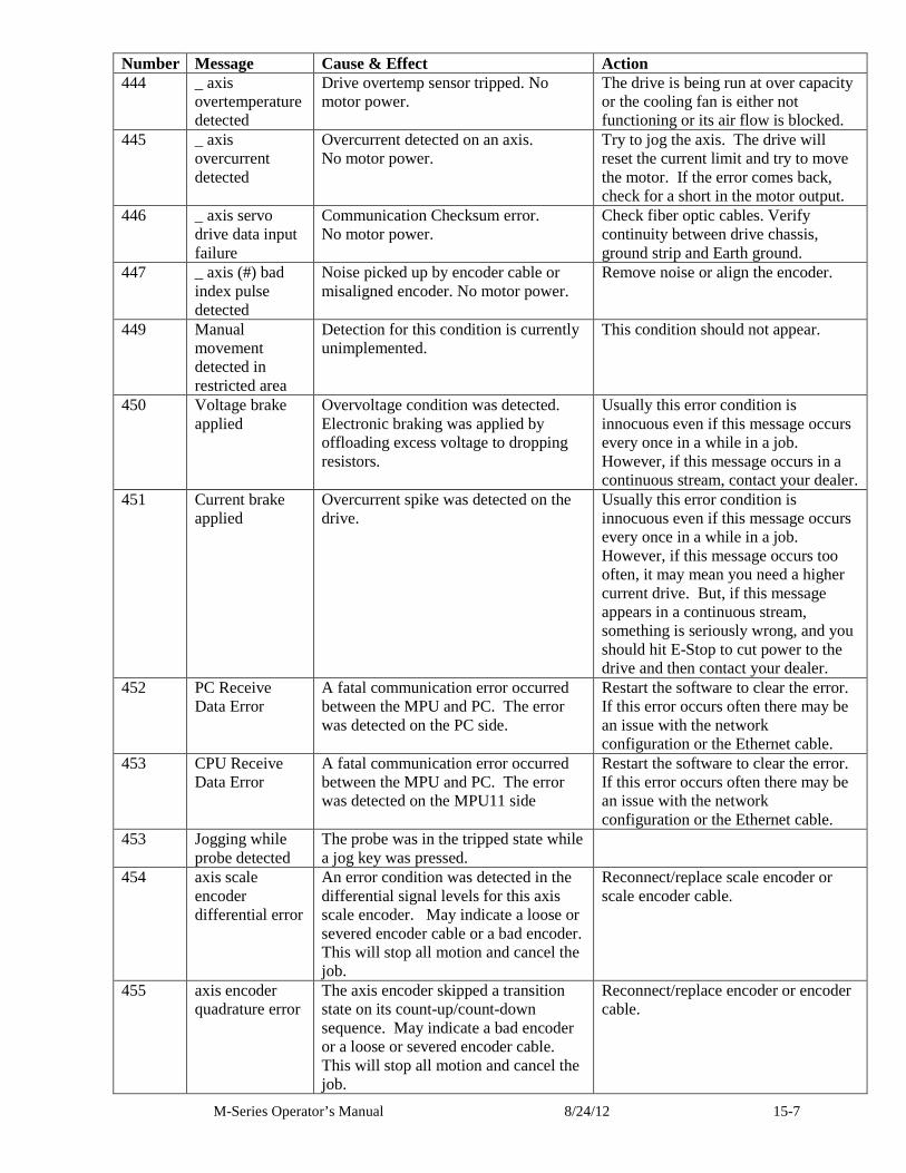
M-Series Operator’s Manual 8/24/12 15-7
Number Message Cause & Effect Action 444 _ axis
overtemperature detected
Drive overtemp sensor tripped. No motor power.
The drive is being run at over capacity or the cooling fan is either not functioning or its air flow is blocked.
445 _ axis overcurrent detected
Overcurrent detected on an axis. No motor power.
Try to jog the axis. The drive will reset the current limit and try to move the motor. If the error comes back, check for a short in the motor output.
446 _ axis servo drive data input failure
Communication Checksum error. No motor power.
Check fiber optic cables. Verify continuity between drive chassis, ground strip and Earth ground.
447 _ axis (#) bad index pulse detected
Noise picked up by encoder cable or misaligned encoder. No motor power.
Remove noise or align the encoder.
449 Manual movement detected in restricted area
Detection for this condition is currently unimplemented.
This condition should not appear.
450 Voltage brake applied
Overvoltage condition was detected. Electronic braking was applied by offloading excess voltage to dropping resistors.
Usually this error condition is innocuous even if this message occurs every once in a while in a job. However, if this message occurs in a continuous stream, contact your dealer.
451 Current brake applied
Overcurrent spike was detected on the drive.
Usually this error condition is innocuous even if this message occurs every once in a while in a job. However, if this message occurs too often, it may mean you need a higher current drive. But, if this message appears in a continuous stream, something is seriously wrong, and you should hit E-Stop to cut power to the drive and then contact your dealer.
452 PC Receive Data Error
A fatal communication error occurred between the MPU and PC. The error was detected on the PC side.
Restart the software to clear the error. If this error occurs often there may be an issue with the network configuration or the Ethernet cable.
453 CPU Receive Data Error
A fatal communication error occurred between the MPU and PC. The error was detected on the MPU11 side
Restart the software to clear the error. If this error occurs often there may be an issue with the network configuration or the Ethernet cable.
453 Jogging while probe detected
The probe was in the tripped state while a jog key was pressed.
454 axis scale encoder differential error
An error condition was detected in the differential signal levels for this axis scale encoder. May indicate a loose or severed encoder cable or a bad encoder. This will stop all motion and cancel the job.
Reconnect/replace scale encoder or scale encoder cable.
455 axis encoder quadrature error
The axis encoder skipped a transition state on its count-up/count-down sequence. May indicate a bad encoder or a loose or severed encoder cable. This will stop all motion and cancel the job.
Reconnect/replace encoder or encoder cable.
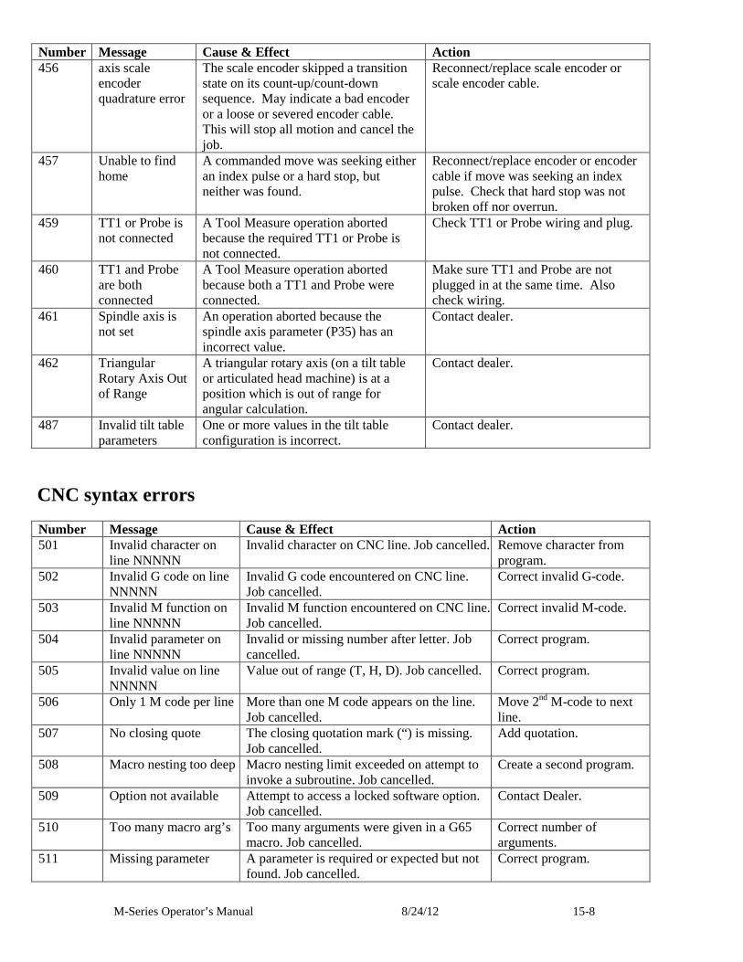
M-Series Operator’s Manual 8/24/12 15-8
Number Message Cause & Effect Action 456 axis scale
encoder quadrature error
The scale encoder skipped a transition state on its count-up/count-down sequence. May indicate a bad encoder or a loose or severed encoder cable. This will stop all motion and cancel the job.
Reconnect/replace scale encoder or scale encoder cable.
457 Unable to find home
A commanded move was seeking either an index pulse or a hard stop, but neither was found.
Reconnect/replace encoder or encoder cable if move was seeking an index pulse. Check that hard stop was not broken off nor overrun.
459 TT1 or Probe is not connected
A Tool Measure operation aborted because the required TT1 or Probe is not connected.
Check TT1 or Probe wiring and plug.
460 TT1 and Probe are both connected
A Tool Measure operation aborted because both a TT1 and Probe were connected.
Make sure TT1 and Probe are not plugged in at the same time. Also check wiring.
461 Spindle axis is not set
An operation aborted because the spindle axis parameter (P35) has an incorrect value.
Contact dealer.
462 Triangular Rotary Axis Out of Range
A triangular rotary axis (on a tilt table or articulated head machine) is at a position which is out of range for angular calculation.
Contact dealer.
487 Invalid tilt table parameters
One or more values in the tilt table configuration is incorrect.
Contact dealer.
CNC syntax errors
Number Message Cause & Effect Action 501 Invalid character on
line NNNNN Invalid character on CNC line. Job cancelled. Remove character from
program. 502 Invalid G code on line
NNNNN Invalid G code encountered on CNC line. Job cancelled.
Correct invalid G-code.
503 Invalid M function on line NNNNN
Invalid M function encountered on CNC line. Job cancelled.
Correct invalid M-code.
504 Invalid parameter on line NNNNN
Invalid or missing number after letter. Job cancelled.
Correct program.
505 Invalid value on line NNNNN
Value out of range (T, H, D). Job cancelled. Correct program.
506 Only 1 M code per line More than one M code appears on the line. Job cancelled.
Move 2nd M-code to next line.
507 No closing quote The closing quotation mark (“) is missing. Job cancelled.
Add quotation.
508 Macro nesting too deep Macro nesting limit exceeded on attempt to invoke a subroutine. Job cancelled.
Create a second program.
509 Option not available Attempt to access a locked software option. Job cancelled.
Contact Dealer.
510 Too many macro arg’s Too many arguments were given in a G65 macro. Job cancelled.
Correct number of arguments.
511 Missing parameter A parameter is required or expected but not found. Job cancelled.
Correct program.
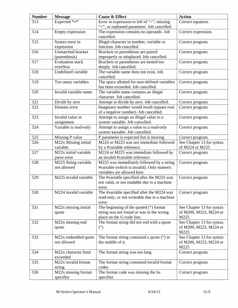
M-Series Operator’s Manual 8/24/12 15-9
Number Message Cause & Effect Action 513 Expected “=” Error in expression to left of “=”, missing
“=”, or orphaned parameter. Job cancelled. Correct equation.
514 Empty expression The expression contains no operands. Job cancelled.
Correct expression.
515 Syntax error in expression
Illegal character in number, variable or function. Job cancelled.
Correct program.
516 Unmatched bracket (parenthesis)
Brackets or parentheses are paired improperly or misplaced. Job cancelled.
Correct program.
517 Evaluation stack overflow
Brackets or parentheses are nested too deeply. Job cancelled.
Correct program.
518 Undefined variable The variable name does not exist. Job cancelled.
Correct program.
519 Too many variables The space allotted for user-defined variables has been exceeded. Job cancelled.
Correct program.
520 Invalid variable name The variable name contains an illegal character. Job cancelled.
Correct program.
521 Divide by zero Attempt to divide by zero. Job cancelled. Correct program. 522 Domain error Imaginary number would result (square root
of a negative number). Job cancelled. Correct program.
523 Invalid value in assignment
Attempt to assign an illegal value to a system variable. Job cancelled.
Correct program.
524 Variable is read-only Attempt to assign a value to a read-only system variable. Job cancelled.
Correct program.
525 Missing P value P parameter is expected but is missing Correct program. 526 M22x Missing initial
variable M224 or M225 was not immediate followed by a #variable reference.
See Chapter 13 for syntax of M224 or M225
527 M22x initial variable parse error
M224 or M225 was immediate followed by an invalid #variable reference.
Correct program.
528 M225 String variable not allowed
M225 was immediately followed by a string #variable (which is invalid). Only numeric variables are allowed here.
Correct program.
529 M225 invalid variable The #variable specified after the M225 was not valid, or not readable due to a machine error.
Correct program.
530 M224 invalid variable The #variable specified after the M224 was read-only, or not writeable due to a machine error.
Correct program.
531 M22x missing initial quote
The beginning of the quoted (“) format string was not found or was in the wrong place on the G-code line.
See Chapter 13 for syntax of M200, M223, M224 or M225
532 M22x missing end quote
The format string did not end with a quote (”)
See Chapter 13 for syntax of M200, M223, M224 or M225
533 M22x embedded quote not allowed
The format string contained a quote (“) in the middle of it.
See Chapter 13 for syntax of M200, M223, M224 or M225
534 M22x character limit exceeded
The format string was too long Correct program.
535 M22x invalid format string
The format string contained invalid format codes
Correct program.
536 M22x missing format specifier
The format code was missing the its specifier
Correct program.
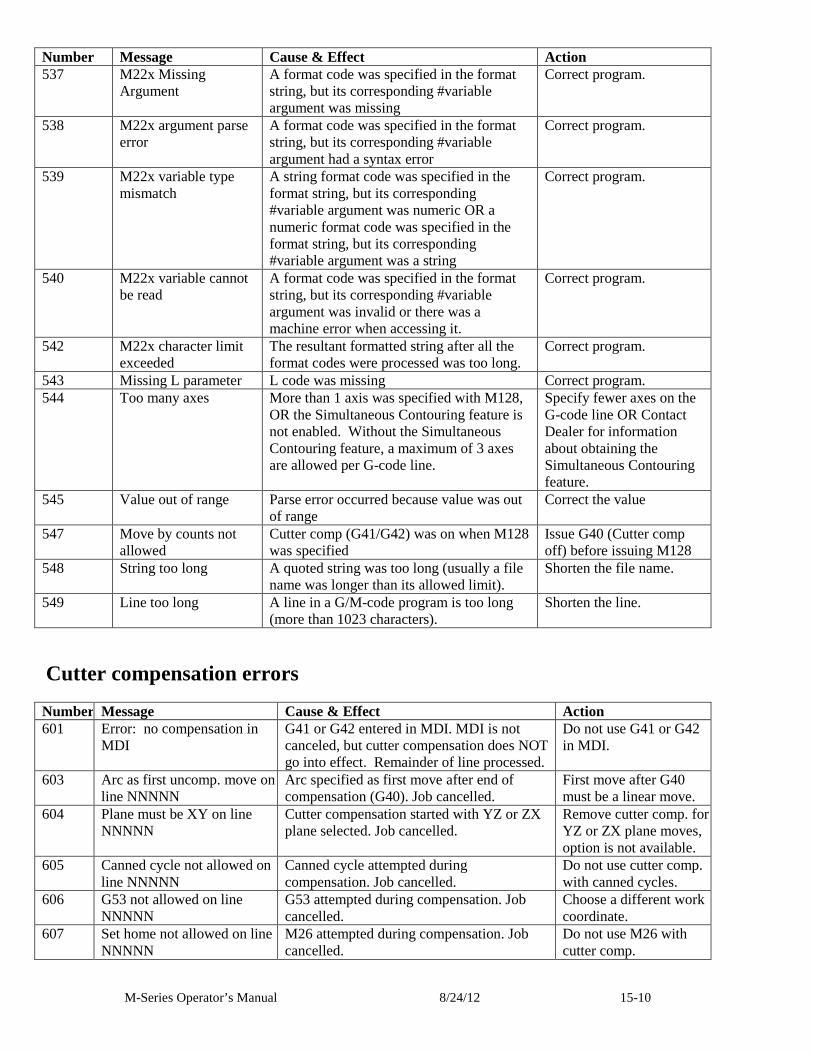
M-Series Operator’s Manual 8/24/12 15-10
Number Message Cause & Effect Action 537 M22x Missing
Argument A format code was specified in the format string, but its corresponding #variable argument was missing
Correct program.
538 M22x argument parse error
A format code was specified in the format string, but its corresponding #variable argument had a syntax error
Correct program.
539 M22x variable type mismatch
A string format code was specified in the format string, but its corresponding #variable argument was numeric OR a numeric format code was specified in the format string, but its corresponding #variable argument was a string
Correct program.
540 M22x variable cannot be read
A format code was specified in the format string, but its corresponding #variable argument was invalid or there was a machine error when accessing it.
Correct program.
542 M22x character limit exceeded
The resultant formatted string after all the format codes were processed was too long.
Correct program.
543 Missing L parameter L code was missing Correct program. 544 Too many axes More than 1 axis was specified with M128,
OR the Simultaneous Contouring feature is not enabled. Without the Simultaneous Contouring feature, a maximum of 3 axes are allowed per G-code line.
Specify fewer axes on the G-code line OR Contact Dealer for information about obtaining the Simultaneous Contouring feature.
545 Value out of range Parse error occurred because value was out of range
Correct the value
547 Move by counts not allowed
Cutter comp (G41/G42) was on when M128 was specified
Issue G40 (Cutter comp off) before issuing M128
548 String too long A quoted string was too long (usually a file name was longer than its allowed limit).
Shorten the file name.
549 Line too long A line in a G/M-code program is too long (more than 1023 characters).
Shorten the line.
Cutter compensation errors
Number Message Cause & Effect Action 601 Error: no compensation in
MDI G41 or G42 entered in MDI. MDI is not canceled, but cutter compensation does NOT go into effect. Remainder of line processed.
Do not use G41 or G42 in MDI.
603 Arc as first uncomp. move on line NNNNN
Arc specified as first move after end of compensation (G40). Job cancelled.
First move after G40 must be a linear move.
604 Plane must be XY on line NNNNN
Cutter compensation started with YZ or ZX plane selected. Job cancelled.
Remove cutter comp. for YZ or ZX plane moves, option is not available.
605 Canned cycle not allowed on line NNNNN
Canned cycle attempted during compensation. Job cancelled.
Do not use cutter comp. with canned cycles.
606 G53 not allowed on line NNNNN
G53 attempted during compensation. Job cancelled.
Choose a different work coordinate.
607 Set home not allowed on line NNNNN
M26 attempted during compensation. Job cancelled.
Do not use M26 with cutter comp.
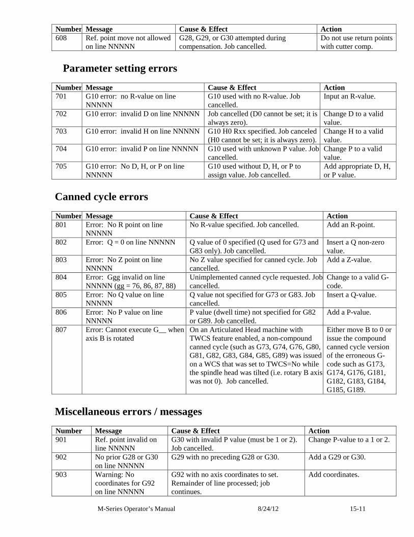
M-Series Operator’s Manual 8/24/12 15-11
Number Message Cause & Effect Action 608 Ref. point move not allowed
on line NNNNN G28, G29, or G30 attempted during compensation. Job cancelled.
Do not use return points with cutter comp.
Parameter setting errors
Number Message Cause & Effect Action 701 G10 error: no R-value on line
NNNNN G10 used with no R-value. Job cancelled.
Input an R-value.
702 G10 error: invalid D on line NNNNN Job cancelled (D0 cannot be set; it is always zero).
Change D to a valid value.
703 G10 error: invalid H on line NNNNN G10 H0 Rxx specified. Job canceled (H0 cannot be set; it is always zero).
Change H to a valid value.
704 G10 error: invalid P on line NNNNN G10 used with unknown P value. Job cancelled.
Change P to a valid value.
705 G10 error: No D, H, or P on line NNNNN
G10 used without D, H, or P to assign value. Job cancelled.
Add appropriate D, H, or P value.
Canned cycle errors
Number Message Cause & Effect Action 801 Error: No R point on line
NNNNN No R-value specified. Job cancelled. Add an R-point.
802 Error: Q = 0 on line NNNNN Q value of 0 specified (Q used for G73 and G83 only). Job cancelled.
Insert a Q non-zero value.
803 Error: No Z point on line NNNNN
No Z value specified for canned cycle. Job cancelled.
Add a Z-value.
804 Error: Ggg invalid on line NNNNN (gg = 76, 86, 87, 88)
Unimplemented canned cycle requested. Job cancelled.
Change to a valid G-code.
805 Error: No Q value on line NNNNN
Q value not specified for G73 or G83. Job cancelled.
Insert a Q-value.
806 Error: No P value on line NNNNN
P value (dwell time) not specified for G82 or G89. Job cancelled.
Add a P-value.
807 Error: Cannot execute G__ when axis B is rotated
On an Articulated Head machine with TWCS feature enabled, a non-compound canned cycle (such as G73, G74, G76, G80, G81, G82, G83, G84, G85, G89) was issued on a WCS that was set to TWCS=No while the spindle head was tilted (i.e. rotary B axis was not 0). Job cancelled.
Either move B to 0 or issue the compound canned cycle version of the erroneous G-code such as G173, G174, G176, G181, G182, G183, G184, G185, G189.
Miscellaneous errors / messages
Number Message Cause & Effect Action 901 Ref. point invalid on
line NNNNN G30 with invalid P value (must be 1 or 2). Job cancelled.
Change P-value to a 1 or 2.
902 No prior G28 or G30 on line NNNNN
G29 with no preceding G28 or G30. Add a G29 or G30.
903 Warning: No coordinates for G92 on line NNNNN
G92 with no axis coordinates to set. Remainder of line processed; job continues.
Add coordinates.
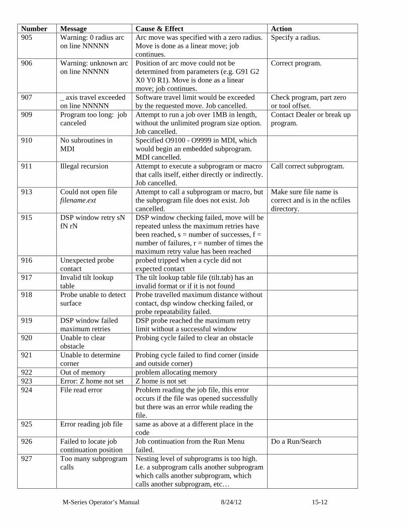
M-Series Operator’s Manual 8/24/12 15-12
Number Message Cause & Effect Action 905 Warning: 0 radius arc
on line NNNNN Arc move was specified with a zero radius. Move is done as a linear move; job continues.
Specify a radius.
906 Warning: unknown arc on line NNNNN
Position of arc move could not be determined from parameters (e.g. G91 G2 X0 Y0 R1). Move is done as a linear move; job continues.
Correct program.
907 _ axis travel exceeded on line NNNNN
Software travel limit would be exceeded by the requested move. Job cancelled.
Check program, part zero or tool offset.
909 Program too long: job canceled
Attempt to run a job over 1MB in length, without the unlimited program size option. Job cancelled.
Contact Dealer or break up program.
910 No subroutines in MDI
Specified O9100 - O9999 in MDI, which would begin an embedded subprogram. MDI cancelled.
911 Illegal recursion Attempt to execute a subprogram or macro that calls itself, either directly or indirectly. Job cancelled.
Call correct subprogram.
913 Could not open file filename.ext
Attempt to call a subprogram or macro, but the subprogram file does not exist. Job cancelled.
Make sure file name is correct and is in the ncfiles directory.
915 DSP window retry sN fN rN
DSP window checking failed, move will be repeated unless the maximum retries have been reached, s = number of successes, f = number of failures, r = number of times the maximum retry value has been reached
916 Unexpected probe contact
probed tripped when a cycle did not expected contact
917 Invalid tilt lookup table
The tilt lookup table file (tilt.tab) has an invalid format or if it is not found
918 Probe unable to detect surface
Probe travelled maximum distance without contact, dsp window checking failed, or probe repeatability failed.
919 DSP window failed maximum retries
DSP probe reached the maximum retry limit without a successful window
920 Unable to clear obstacle
Probing cycle failed to clear an obstacle
921 Unable to determine corner
Probing cycle failed to find corner (inside and outside corner)
922 Out of memory problem allocating memory 923 Error: Z home not set Z home is not set 924 File read error Problem reading the job file, this error
occurs if the file was opened successfully but there was an error while reading the file.
925 Error reading job file same as above at a different place in the code
926 Failed to locate job continuation position
Job continuation from the Run Menu failed.
Do a Run/Search
927 Too many subprogram calls
Nesting level of subprograms is too high. I.e. a subprogram calls another subprogram which calls another subprogram, which calls another subprogram, etc…
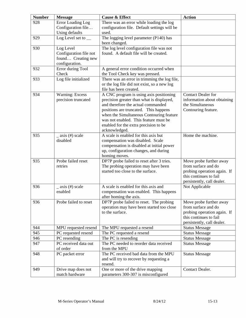
M-Series Operator’s Manual 8/24/12 15-13
Number Message Cause & Effect Action 928 Error Loading Log
Configuration file… Using defaults
There was an error while loading the log configuration file. Default settings will be used.
929 Log Level set to __ The logging level parameter (P140) has been changed.
930 Log Level Configuration file not found… Creating new configuration.
The log level configuration file was not found. A default file will be created.
932 Error during Tool Check
A general error condition occurred when the Tool Check key was pressed.
933 Log file initialized There was an error in trimming the log file, or the log file did not exist, so a new log file has been created.
934 Warning: Excess precision truncated
A CNC program is using axis positioning precision greater than what is displayed, and therefore the actual commanded positions are truncated. This happens when the Simultaneous Contouring feature was not enabled. This feature must be enabled for the extra precision to be acknowledged.
Contact Dealer for information about obtaining the Simultaneous Contouring feature.
935 _ axis (#) scale disabled
A scale is enabled for this axis but compensation was disabled. Scale compensation is disabled at initial power up, configuration changes, and during homing moves.
Home the machine.
935 Probe failed reset retries
DP7P probe failed to reset after 3 tries. The probing operation may have been started too close to the surface.
Move probe further away from surface and do probing operation again. If this continues to fail persistently, call dealer.
936 _ axis (#) scale enabled
A scale is enabled for this axis and compensation was enabled. This happens after homing the axis.
Not Applicable
936 Probe failed to reset DP7P probe failed to reset. The probing operation may have been started too close to the surface.
Move probe further away from surface and do probing operation again. If this continues to fail persistently, call dealer.
944 MPU requested resend The MPU requested a resend Status Message 945 PC requested resend The PC requested a resend Status Message 946 PC resending The PC is resending Status Message 947 PC received data out
of order The PC needed to reorder data received from the MPU
Status Message
948 PC packet error The PC received bad data from the MPU and will try to recover by requesting a resend.
Status Message
949 Drive map does not match hardware
One or more of the drive mapping parameters 300-307 is misconfigured
Contact Dealer.
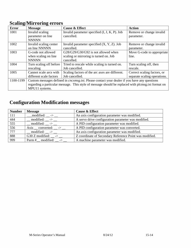
M-Series Operator’s Manual 8/24/12 15-14
Scaling/Mirroring errors Error Message Cause & Effect Action 1001 Invalid scaling
parameter on line NNNNN
Invalid parameter specified (I, J, K, P). Job cancelled.
Remove or change invalid parameter.
1002 Invalid scaling center on line NNNNN
Invalid parameter specified (X, Y, Z). Job cancelled.
Remove or change invalid parameter.
1003 G-code not allowed when scaling on line NNNNN
G28/G29/G30/G92 is not allowed when scaling or mirroring is turned on. Job cancelled.
Move G-code to appropriate line.
1004 Turn scaling off before rescaling
Tried to rescale while scaling is turned on. Job cancelled.
Turn scaling off, then rescale.
1005 Cannot scale arcs with different scale factors
Scaling factors of the arc axes are different. Job cancelled.
Correct scaling factors, or separate scaling operations.
1100-1199 Custom messages defined in cncxmsg.txt. Please contact your dealer if you have any questions regarding a particular message. This style of message should be replaced with plcmsg.txt format on MPU11 systems.
Configuration Modification messages
Number Message Cause & Effect 111 ___modified: __ -> __ An axis configuration parameter was modified. 444 __ modified: __ -> __ A servo drive configuration parameter was modified. 555 __ modified: __ -> __ A PID configuration parameter was modified. 556 Axis __ converted: __ -> __ A PID configuration parameter was converted. 777 __ modified: __ -> __ An axis configuration parameter was modified. 888 G30 Z modified: __ -> __ Z coordinate of Secondary Reference Point was modified. 999 Parm #__ modified: __ -> __ A machine parameter was modified.


![OneCNC Solid Design AA Mill Express Mill …OneCNC Solid Design AA Mill Express Mill Advantage Design 280,000B (ü%l]) 280,000B 480,000B 28 Milling & Multi Axis Mill 800,000B Mill](https://img.pdfslide.us/doc/110x75/5f867f1cac5a475cf73aa2f7/onecnc-solid-design-aa-mill-express-mill-onecnc-solid-design-aa-mill-express-mill.jpg)