Embed Size (px)
Citation preview

V246 Series 2-Way Pressure-ActuatedWater-Regulating Valves for High-Pressure
Refrigerants Product Bulletin
DescriptionThe V246 Series 2-Way Pressure-Actuated Water-Regulating Valves for High-Pressure Refrigerants comein two types of control action: direct acting and reverseacting. V246 valves regulate water flow to controlrefrigerant head pressure in systems with water-cooledcondensers.The V246 Series Valves are available in 3/8 in. through 2in. sizes and have a maximum allowable water pressureof 150 psi (10.3 bar). Direct acting V246 valves have anadjustable opening point in a refrigerant pressure rangeof 200 to 400 psi (13.8 to 27.6 bar), and reverse actingvalves have a range of 135 to 300 psi (9.3 to 20.7 bar).V246 valves may be used with standard non-corrosiverefrigerants.Maritime models, which have nickel copper (Monel®)internal parts, are available for applications where themedia may be corrosive to the internal parts.
Warning
WarningThis product is made of copper alloy, which containslead. The product is therefore not to be used on drink-ing water.
Figure 1: Figure 1: V246 Series Valve
Features and BenefitsNo Close Fitting or Sliding Parts in Water Passages
Provides robust control in less than idealconditions.
Accessible Range Spring
Allows easy manual flushing.
Take-Apart Construction
Allows access to valve interior without removingvalve from refrigeration system or pumping downthe system.
Pressure-Balanced Design
Resists changes to setpoint caused by gradual orsudden water pressure changes.
Corrosion-Resistant Material for Internal Parts
Promotes long valve life.
ApplicationImportant: The V246 Series 2-Way Pressure-Actuated Water-Regulating Valves for High-PressureRefrigerants is intended to control water or coolantflow under normal operating conditions. Wherefailure or malfunction of the V246 valve couldlead to personal injury or property damage to thecontrolled equipment or other property, additionalprecautions must be designed into the controlsystem. Incorporate and maintain other devices,such as supervisory or alarm systems or safety orlimit controls, intended to warn of or protect againstfailure or malfunction of the V246 valve.
LIT-12011514
2019-06-13
V246

OperationThe V246 valve controls refrigerant head pressure bysensing the condensing pressure and adjusting waterflow as the condenser requirements change.
Valve SizingEach application is unique and requires specificengineering data to properly size and design a system tofulfill the appropriate requirements. Typically, a valve isreplaced with another valve of the same size in a properlysized and engineered system.To make a rough field estimate of the size of valve foran application, find the valve size needed by locating apoint on a flow chart (see Figure 6 through Figure 11) thatsatisfies these requirements:• water flow required by the condenser (Flow)• refrigerant head pressure rise (PRISE)
• available water pressure (PAVAIL)
Follow these steps, and use the information obtainedto locate a point on one of the flowcharts (see Figure 6through Figure 11) that satisfies all three steps.1. Take the water flow required by the condenser
(Flow) from information provided by themanufacturer of the condensing unit. If themanufacturer’s information is unavailable, use thefollowing information and Figure 2 to make a roughapproximation of water flow in gallons per minute(gpm) [cubic meters per hour (m3/hr)]:
- System Capacity (Tons of Refrigeration)- Outlet Water Temperature (Temp. Outlet)
- Inlet Water Temperature (Temp. Inlet)
Calculate the flow using the following formula:
Figure 2: Flow Required
Note: If the outlet temperature is unknown,assume it to be 10F° (6C° ) above the inlettemperature.
2. Determine refrigerant head pressure rise above thevalve opening point (PRISE) using Figure 4 and thefollowing steps:
a. The Valve Closing Pressure (PCLOSE)is equal to the refrigerant pressure atthe highest ambient temperature therefrigeration equipment experiences inthe Off cycle. Use a Pressure-TemperatureChart for the refrigerant selected to find thispressure.
b. To approximate the Valve Opening Pressure(POPEN), add about 10 psi (0.7 bar) to the
Valve Closing Pressure. See Figure 3.Note: Add about 20 psi (1.4 bar) for 3/8in. valves.
Figure 3: Valve Opening Pressure
c. From the Pressure-Temperature Chartfor the refrigerant selected, read theRefrigerant Condensing Pressure (PCOND)(operating head pressure) corresponding tothe selected condensing temperature.
d. Subtract the Valve Opening Pressure fromthe Refrigerant Condensing Pressure. Thisgives the head pressure rise. See Figure 4.
Figure 4: Refrigerant Head Pressure Rise
3. Determine the available water pressure to the valve(PAVAIL) using the following steps and Figure 5. Thisis the actual water pressure available to force waterthrough the valve.
a. Determine the inlet pressure (PIN). This isthe water pressure from city water mains,pumps, or other sources.
b. Pressure drop through condenser (ΔPCOND)is the difference in water pressure betweenthe condenser inlet and the condenseroutlet. Obtain this information from thecondenser manufacturer.
c. Estimate or calculate the pressure dropthrough all associated piping (PLOSS).
d. Subtract the ΔPCOND and PLOSS from PIN.The result is PAVAIL.
Figure 5: Available Water Pressure
V246 Series 2-Way Pressure-Actuated Water-Regulating Valves for High-Pressure Refrigerants Product Bulletin2
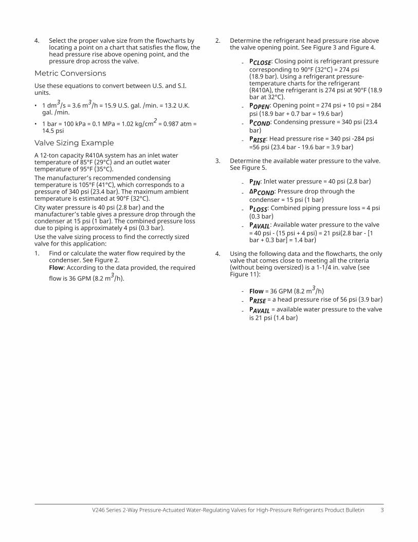
4. Select the proper valve size from the flowcharts bylocating a point on a chart that satisfies the flow, thehead pressure rise above opening point, and thepressure drop across the valve.
Metric ConversionsUse these equations to convert between U.S. and S.I.units.
• 1 dm3/s = 3.6 m3/h = 15.9 U.S. gal. /min. = 13.2 U.K.gal. /min.
• 1 bar = 100 kPa = 0.1 MPa = 1.02 kg/cm2 = 0.987 atm =14.5 psi
Valve Sizing ExampleA 12-ton capacity R410A system has an inlet watertemperature of 85°F (29°C) and an outlet watertemperature of 95°F (35°C).The manufacturer’s recommended condensingtemperature is 105°F (41°C), which corresponds to apressure of 340 psi (23.4 bar). The maximum ambienttemperature is estimated at 90°F (32°C).City water pressure is 40 psi (2.8 bar) and themanufacturer’s table gives a pressure drop through thecondenser at 15 psi (1 bar). The combined pressure lossdue to piping is approximately 4 psi (0.3 bar).Use the valve sizing process to find the correctly sizedvalve for this application:1. Find or calculate the water flow required by the
condenser. See Figure 2.Flow: According to the data provided, the requiredflow is 36 GPM (8.2 m3/h).
2. Determine the refrigerant head pressure rise abovethe valve opening point. See Figure 3 and Figure 4.
- PCLOSE: Closing point is refrigerant pressurecorresponding to 90°F (32°C) = 274 psi(18.9 bar). Using a refrigerant pressure-temperature charts for the refrigerant(R410A), the refrigerant is 274 psi at 90°F (18.9bar at 32°C).
- POPEN: Opening point = 274 psi + 10 psi = 284psi (18.9 bar + 0.7 bar = 19.6 bar)
- PCOND: Condensing pressure = 340 psi (23.4bar)
- PRISE: Head pressure rise = 340 psi -284 psi=56 psi (23.4 bar - 19.6 bar = 3.9 bar)
3. Determine the available water pressure to the valve.See Figure 5.
- PIN: Inlet water pressure = 40 psi (2.8 bar)
- ΔPCOND: Pressure drop through thecondenser = 15 psi (1 bar)
- PLOSS: Combined piping pressure loss = 4 psi(0.3 bar)
- PAVAIL: Available water pressure to the valve= 40 psi - (15 psi + 4 psi) = 21 psi(2.8 bar - [1bar + 0.3 bar] = 1.4 bar)
4. Using the following data and the flowcharts, the onlyvalve that comes close to meeting all the criteria(without being oversized) is a 1-1/4 in. valve (seeFigure 11):
- Flow = 36 GPM (8.2 m3/h)- PRISE = a head pressure rise of 56 psi (3.9 bar)
- PAVAIL = available water pressure to the valveis 21 psi (1.4 bar)
V246 Series 2-Way Pressure-Actuated Water-Regulating Valves for High-Pressure Refrigerants Product Bulletin 3

V246 FlowchartsThe maximum recommended differential water pressure across a valve is 60 psi (4.1 bar).Figure 6: 3/8 in. Direct Acting Low-Flow Valve Flowchart
Figure 7: 3/8 in. Direct Acting Valve Flowchart
V246 Series 2-Way Pressure-Actuated Water-Regulating Valves for High-Pressure Refrigerants Product Bulletin4

Figure 8: 1/2 in. Direct Acting Valve Flowchart
Figure 9: 3/4 in. Direct Acting Valve Flowchart
V246 Series 2-Way Pressure-Actuated Water-Regulating Valves for High-Pressure Refrigerants Product Bulletin 5

Figure 10: 1 in. Direct Acting Valve Flowchart
Figure 11: 1-1/4 in. Direct Acting Valve Flowchart
V246 Series 2-Way Pressure-Actuated Water-Regulating Valves for High-Pressure Refrigerants Product Bulletin6

Figure 12: 1-1/2 in. Direct Acting Valve Flowchart
Figure 13: 2 in. Direct Acting Valve Flowchart
V246 Series 2-Way Pressure-Actuated Water-Regulating Valves for High-Pressure Refrigerants Product Bulletin 7

Dimensions
Figure 14: V246 Screw Connection Valves Dimensions
Figure 15: V246 Angle-Body Screw Connection ValvesDimensions
Table 1: V246 Screw Connection Valves Dimensions
Dimensions in Inches (Millimeters)Valve SizeA B C D E
3/8 in. 2-5/8 (67) 1-5/8 (41) 6-1/2 (166) 3-1/2 (89) 3 (77)1/2 in. 3-1/16 (78) 2 (51) 7-3/16 (182) 3-13/16 (96) 3-3/8 (86)3/4 in. 3-3/8 (86) 2-3/16 (55) 8 (203) 4-3/16 (106) 3-13/16 (98)1 in. 4-3/4 (121) 2-13/16 (71) 10-1/2 (267) 5-15/16 (151) 4-9/16 (116)1-1/4 in. 4-3/4 (121) 2-13/16 (71) 10-7/8 (276) 6-1/8 (156) 4-3/4 (121)
Table 2: V246 Angle-Body Screw Connection Valves Dimensions
Dimensions in Inches (Millimeters)Valve SizeA B C D E
3/8 in. 2-3/4 (70) 1-5/8 (41) 6-15/16 (176) 3-5/8 (92) 3-1/8 (80)1/2 in. 3-1/8 (80) 2 (51) 7-1/2 (191) 3-7/8 (98) 3-1/2 (88)3/4 in. 3-9/16 (90) 2-1/8 (55) 8-9/16 (217) 4-5/16 (110) 4 (101)
V246 Series 2-Way Pressure-Actuated Water-Regulating Valves for High-Pressure Refrigerants Product Bulletin8

Figure 16: V246 Union Sweat Connection Valves Dimensions
Table 3: V246 Union Sweat Connection Valves Dimensions
Dimensions in Inches (Millimeters)Valve SizeA B C D E
1-1/4 in. 4-3/4 (121) 2-13/16 (71) 10-7/8 (276) 6-1/8 (156) 4-3/4 (121)
Figure 17: V246 Flange Valve Dimensions
Table 4: V246 Flange Valve, Commercial Service - Dimensions
Dimensions in Inches (Millimeters)Valve SizeA B C D E F G H
1-1/2 in. 5-5/16(135)
9/16 (14) 6 -1/8 (156) 4-3/4 (121) 10-7/8(276)
15-1/4 (133)1 2-5/8 (67) 1-7/8 (48)
2 in. 6-5/8 (168) 5/8 (16) 7-1/8 (181) 6-1/8 (156) 13-1/4(336)
26-3/16(157)2
3-1/2 (89) 2-1/4 (57)
1 The dimensions on the European versions are 5-29/32 in. (150 mm).2 The dimensions on the European versions are 6-1/2 in. (165 mm).
Table 5: V246 Flange Valve, Commercial Service - Flange Specifications
Valve Size Regional Version Number of Holes Hole Size Bolt Circle1-1/2 in. 5/8 in. (16 mm) 3-7/8 in. (98 mm)2 in.
North American 43/4 in. (19 mm) 4-3/4 in. (121 mm)
V246 Series 2-Way Pressure-Actuated Water-Regulating Valves for High-Pressure Refrigerants Product Bulletin 9

Table 5: V246 Flange Valve, Commercial Service - Flange Specifications
Valve Size Regional Version Number of Holes Hole Size Bolt Circle1-1/2 in. 110 mm2 in.
European, DIN2533Flanges
4 18 mm125 mm
Table 6: V246 Flange Valve, Maritime Service - Dimensions
Dimensions in Inches (Millimeters)Valve SizeA B C D E F G H
1-1/2 in. 5-5/16 (135) 9/16 (14) 6 -1/8 (156) 4-3/4 (121) 10-7/8 (276) 15-1/4 (133)1 2-5/8 (67) 1-7/8 (48)
2 in. 6-3/8 (162) 5/8 (16) 7-1/8 (181) 6-1/8 (156) 13-1/4 (337) 26 (152)2 3-1/2 (89) 2-3/4 (70)
1 The dimensions on the European versions are 5-29/32 in. (150 mm).2 The dimensions on the European versions are 6-1/2 in. (165 mm).
Table 7: V246 Flange Valve, Maritime Service - Flange Specifications
Valve Size Regional Version Number of Holes Hole Size Bolt Circle1-1/2 in. 5/8 in. (16 mm) 3-7/8 in. (98 mm)2 in.
North American 43/4 in. (19 mm) 4-3/4 in. (121 mm)
1-1/2 in. 110 mm2 in.
European, DIN86021Flanges
4 18 mm125 mm
Stock ModelsWhen ordering V246 valves, specify the complete product code number. See Table 8 and Table 9.Table 8: North American Standard Production Models
Product CodeNumber
Construction Valve Size and Connection ElementStyle
Shipping Weight,lb (kg)
V246GA1-001C Direct Acting 11, Commercial 3/8 in. NPT Screw Style 5 1.8 (0.8)
V246GB1-001C Direct Acting 1, Commercial 1/2 in. NPT Screw Style 5 3.0 (1.4)
V246GC1-001C Direct Acting 1, Commercial 3/4 in. NPT Screw Style 5 3.7 (1.7)
V246GD1-001C Direct Acting 1, Commercial 1 in. NPT Screw Style 5 9.3 (4.2)
V246GE1-001C Direct Acting 1, Commercial 1-1/4 in. NPT Screw Style 5 10 (4.5)
V246GM1-001C Direct Acting 1, Commercial 1-1/4 in. Union Sweat Style 5 10 (4.5)
V246GR1-001C Direct Acting 1, Commercial 1-1/2 in. Flange Style 5 13.6 (6.2)
V246GS1-001C Direct Acting 1, Commercial 2 in. Flange Style 5 27 (12.3)
V246HA1-001C Direct Acting 1, Maritime 3/8 in. NPT Screw Style 5 1.8 (0.8)
V246HB1-001C Direct Acting 1, Maritime 1/2 in. NPT Screw Style 5 3.0 (1.4)
V246HC1-001C Direct Acting 1, Maritime 3/4 in. NPT Screw Style 5 4.3 (2.0)
V246HD1-001C Direct Acting 1, Maritime 1 in. NPT Screw Style 5 9.5 (4.3)
V246HE1-001C Direct Acting 1, Maritime 1-1/4 in. NPT Screw Style 5 10.3 (4.7)
V246HR1-001C Direct Acting 1, Maritime 1-1/2 in. American Societyof Mechanical Engineers(ASME) Flange
Style 5 13.6 (6.2)
V246HS1-001C Direct Acting 1, Maritime 2 in. ASME Flange Style 5 27 (12.3)
V246 Series 2-Way Pressure-Actuated Water-Regulating Valves for High-Pressure Refrigerants Product Bulletin10
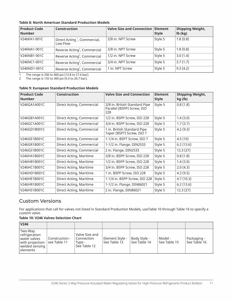
Table 8: North American Standard Production Models
Product CodeNumber
Construction Valve Size and Connection ElementStyle
Shipping Weight,lb (kg)
V246KA1-001C Direct Acting 1, Commercial,Low Flow
3/8 in. NPT Screw Style 5 1.8 (0.8)
V246NA1-001C Reverse Acting22, Commercial 3/8 in. NPT Screw Style 5 1.8 (0.8)
V246NB1-001C Reverse Acting2, Commercial 1/2 in. NPT Screw Style 5 3.0 (1.4)
V246NC1-001C Reverse Acting2, Commercial 3/4 in. NPT Screw Style 5 3.7 (1.7)
V246ND1-001C Reverse Acting2, Commercial 1 in. NPT Screw Style 5 9.3 (4.2)
1 The range is 200 to 400 psi (13.8 to 27.6 bar).2 The range is 135 to 300 psi (9.3 to 20.7 bar).
Table 9: European Standard Production Models
Product CodeNumber
Construction Valve Size and Connection ElementStyle
Shipping Weight,kg (lb)
V246GA1A001C Direct Acting, Commercial 3/8 in. British Standard PipeParallel (BSPP) Screw, ISO228
Style 5 0.8 (1.8)
V246GB1A001C Direct Acting, Commercial 1/2 in. BSPP Screw, ISO 228 Style 5 1.4 (3.0)V246GC1A001C Direct Acting, Commercial 3/4 in. BSPP Screw, ISO 228 Style 5 1.7 (3.7)V246GD1B001C Direct Acting, Commercial 1 in. British Standard Pipe
Taper (BSPT) Screw, ISO 7Style 5 4.2 (9.3)
V246GE1B001C Direct Acting, Commercial 1-1/4 in. BSPT Screw, ISO 7 Style 5 4.5 (10)V246GR1B001C Direct Acting, Commercial 1-1/2 in. Flange, DIN2533 Style 5 6.2 (13.6)V246GS1B001C Direct Acting, Commercial 2 in. Flange, DIN2533 Style 5 12.3 (27)V246HA1B001C Direct Acting, Maritime 3/8 in. BSPP Screw, ISO 228 Style 5 0.8 (1.8)V246HB1B001C Direct Acting, Maritime 1/2 in. BSPP Screw, ISO 228 Style 5 1.4 (3.0)V246HC1B001C Direct Acting, Maritime 3/4 in. BSPP Screw, ISO 228 Style 5 2.0 (4.3)V246HD1B001C Direct Acting, Maritime 1 in. BSPP Screw, ISO 228 Style 5 4.3 (9.5)V246HE1B001C Direct Acting, Maritime 1-1/4 in. BSPP Screw, ISO 228 Style 5 4.7 (10.3)V246HR1B001C Direct Acting, Maritime 1-1/2 in. Flange, DIN86021 Style 5 6.2 (13.6)V246HS1B001C Direct Acting, Maritime 2 in. Flange, DIN86021 Style 5 12.3 (27)
Custom VersionsFor applications that call for valves not listed in Standard Production Models, useTable 10 through Table 16 to specify acustom valve.Table 10: V246 Valves Selection Chart
V246
Two-Wayrefrigerationwater valveswith projection-welded sensingelements
Construction -see Table 11
Valve Size andConnectionType -See Table 12
Element Style -See Table 13
Body Style -See Table 14
Model -See Table 15
Packaging -See Table 16
V246 Series 2-Way Pressure-Actuated Water-Regulating Valves for High-Pressure Refrigerants Product Bulletin 11

Table 11: Construction and Pressure Range
Symbol Construction and Pressure Range
G Direct Acting, Commercial, High PressureRange 200 to 400 psi (13.8 to 27.6 bar)
H Direct Acting, Maritime, High Pressure Range200 to 400 psi (13.8 to 27.6 bar)
J Direct Acting, Navy-Certified, High PressureRange 200 to 400 psi (13.8 to 27.6 bar)
KDirect Acting, Commercial, Low Flow, HighPressure Range 200 to 400 psi (13.8 to 27.6bar)
N Reverse Acting, Commercial, High PressureRange 135 to 300 psi (9.3 to 20.7 bar)
V Other
Table 12: Valve Size and Connection Type
Symbol Valve Size and Connection TypeA 3/8 in. Screw ConnectionB 1/2 in. Screw ConnectionC 3/4 in. Screw ConnectionD 1 in. Screw ConnectionE 1-1/4 in. Screw ConnectionL 1 in. Union, Sweat ConnectionM 1-1/4 in. Union, Sweat ConnectionR 1-1/2 in. tradesize, Flange ConnectionS 2 in. tradesize, Flange ConnectionV Other
Table 13: Element Style
Symbol Element Style Description
1 Style 5 1/4 in. male flare (7/16 - 20UNF)
7 Other Reference Custom ModelNumber for information
Table 14: Body Style
Symbol Body Style-- Inches, Straight BodyA Metric, Angle BodyB Metric, Straight Body
Table 15: Model
Symbol Model001 Standard Construction002 (andabove)
Deviation from Standard
Table 16: Packaging
Symbol PackagingC IndividualD Bulk
Repair InformationRepairs can be made. Replacement sensing elements, internal parts and diaphragms are available. To obtainreplacement parts kits instructions and details:• In North America, contact Johnson Controls® Product Sales Operations Team at 1-800-275-5676.• In Europe, contact your local sales office.For North American replacement parts kits product code numbers, see Table 17. For European replacement parts kitsproduct code numbers, see Table 18.Table 17: North American Replacement Parts Kits
NominalValve Size
Valve Type Seat ReplacementParts Kit Product CodeNumber
DiaphragmReplacement Parts KitProduct Code Number
Sensing ElementReplacement Parts KitProduct Code Number
Commercial STT14A-600R3/8 in.Maritime/Navy STT14A-601R
DPM14A-600R SEP93A-600R
Commercial STT14A-603R3/8 in. LowFlow Maritime/Navy Not Applicable
DPM14A-600R SEP93A-600R
Commercial STT15A-602R1/2 in.Maritime/Navy STT15A-603R
DPM15A-602R SEP93A-601R
Commercial STT16A-601R3/4 in.Maritime/Navy STT17A-613R
DPM16A-601R SEP93A-602R
V246 Series 2-Way Pressure-Actuated Water-Regulating Valves for High-Pressure Refrigerants Product Bulletin12
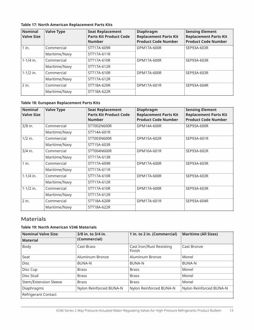
Table 17: North American Replacement Parts Kits
NominalValve Size
Valve Type Seat ReplacementParts Kit Product CodeNumber
DiaphragmReplacement Parts KitProduct Code Number
Sensing ElementReplacement Parts KitProduct Code Number
Commercial STT17A-609R1 in.Maritime/Navy STT17A-611R
DPM17A-600R SEP93A-603R
Commercial STT17A-610R1-1/4 in.Maritime/Navy STT17A-612R
DPM17A-600R SEP93A-603R
Commercial STT17A-610R1-1/2 in.Maritime/Navy STT17A-612R
DPM17A-600R SEP93A-603R
Commercial STT18A-620R2 in.Maritime/Navy STT18A-622R
DPM17A-601R SEP93A-604R
Table 18: European Replacement Parts Kits
NominalValve Size
Valve Type Seat ReplacementParts Kit Product CodeNumber
DiaphragmReplacement Parts KitProduct Code Number
Sensing ElementReplacement Parts KitProduct Code Number
Commercial STT002N600R3/8 in.Maritime/Navy STT14A-601R
DPM14A-600R SEP93A-600R
Commercial STT003N600R1/2 in.Maritime/Navy STT15A-603R
DPM15A-602R SEP93A-601R
Commercial STT004N600R3/4 in.Maritime/Navy STT17A-613R
DPM16A-601R SEP93A-602R
Commercial STT17A-609R1 in.Maritime/Navy STT17A-611R
DPM17A-600R SEP93A-603R
Commercial STT17A-610R1-1/4 in.Maritime/Navy STT17A-612R
DPM17A-600R SEP93A-603R
Commercial STT17A-610R1-1/2 in.Maritime/Navy STT17A-612R
DPM17A-600R SEP93A-603R
Commercial STT18A-620R2 in.Maritime/Navy STT18A-622R
DPM17A-601R SEP93A-604R
MaterialsTable 19: North American V246 Materials
Nominal Valve Size:Material
3/8 in. to 3/4 in.(Commercial)
1 in. to 2 in. (Commercial) Maritime (All Sizes)
Body Cast Brass Cast Iron/Rust ResistingFinish
Cast Bronze
Seat Aluminum Bronze Aluminum Bronze MonelDisc BUNA-N BUNA-N BUNA-NDisc Cup Brass Brass MonelDisc Stud Brass Brass MonelStem/Extension Sleeve Brass Brass MonelDiaphragms Nylon Reinforced BUNA-N Nylon Reinforced BUNA-N Nylon Reinforced BUNA-NRefrigerant Contact
V246 Series 2-Way Pressure-Actuated Water-Regulating Valves for High-Pressure Refrigerants Product Bulletin 13
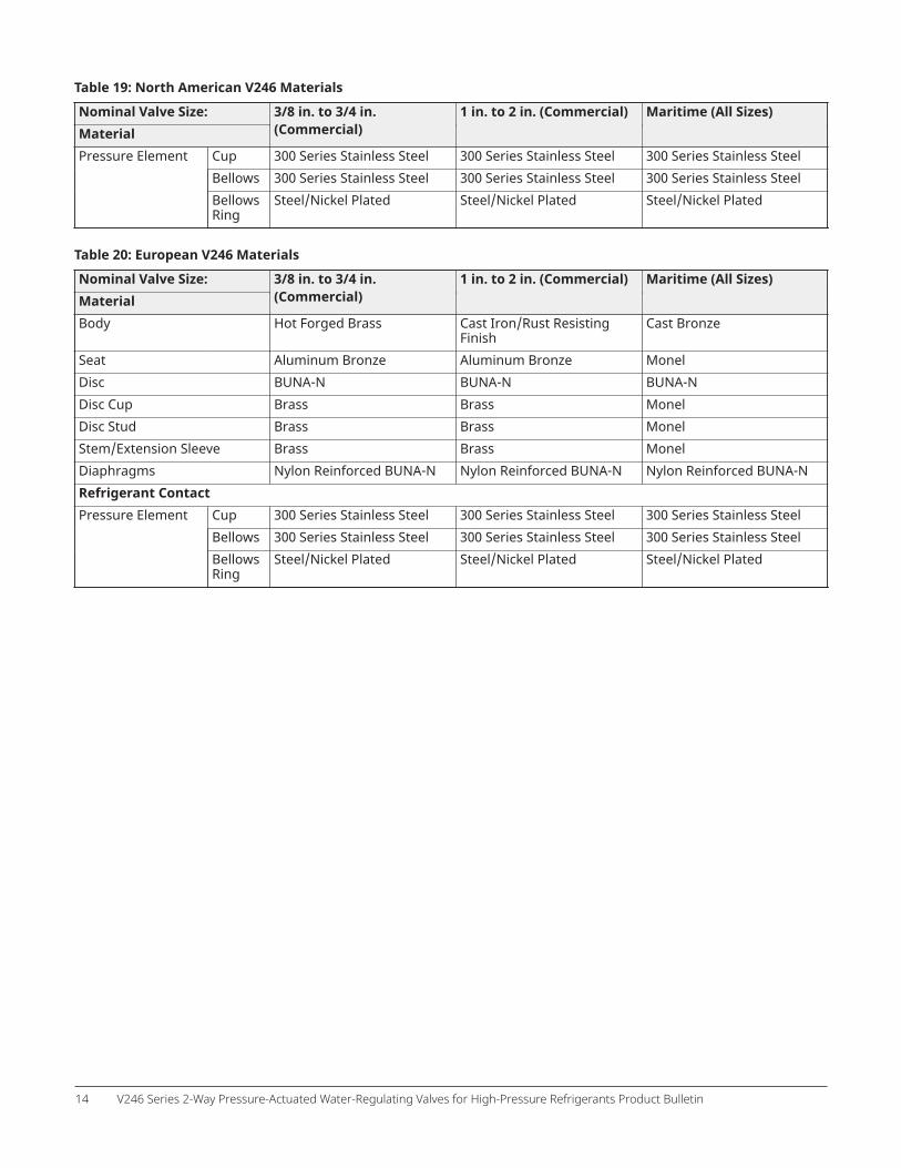
Table 19: North American V246 Materials
Nominal Valve Size:Material
3/8 in. to 3/4 in.(Commercial)
1 in. to 2 in. (Commercial) Maritime (All Sizes)
Cup 300 Series Stainless Steel 300 Series Stainless Steel 300 Series Stainless SteelBellows 300 Series Stainless Steel 300 Series Stainless Steel 300 Series Stainless Steel
Pressure Element
BellowsRing
Steel/Nickel Plated Steel/Nickel Plated Steel/Nickel Plated
Table 20: European V246 Materials
Nominal Valve Size:Material
3/8 in. to 3/4 in.(Commercial)
1 in. to 2 in. (Commercial) Maritime (All Sizes)
Body Hot Forged Brass Cast Iron/Rust ResistingFinish
Cast Bronze
Seat Aluminum Bronze Aluminum Bronze MonelDisc BUNA-N BUNA-N BUNA-NDisc Cup Brass Brass MonelDisc Stud Brass Brass MonelStem/Extension Sleeve Brass Brass MonelDiaphragms Nylon Reinforced BUNA-N Nylon Reinforced BUNA-N Nylon Reinforced BUNA-NRefrigerant Contact
Cup 300 Series Stainless Steel 300 Series Stainless Steel 300 Series Stainless SteelBellows 300 Series Stainless Steel 300 Series Stainless Steel 300 Series Stainless Steel
Pressure Element
BellowsRing
Steel/Nickel Plated Steel/Nickel Plated Steel/Nickel Plated
V246 Series 2-Way Pressure-Actuated Water-Regulating Valves for High-Pressure Refrigerants Product Bulletin14

Technical SpecificationsTable 21: V246 Series 2-Way Pressure-Actuated Water-Regulating Valves for High-Pressure Refrigerants
Factory-Set Opening Point • Direct Acting 200 psi (13.8 bar)• Reverse Acting 165 psi (11.4 bar)
Maximum Working Pressure 630 psi (43.4 bar)Opening Point AdjustmentRange
• Direct Acting 200 to 400 psi (13.8 to 27.6 bar)• Reverse Acting 135 to 300 psi (9.3 to 20.7 bar)
Media 150 psi (10.3 bar) Maximum,-4°F to 170°F (-20°C to 77°C) glycol/water or liquids with low freezing points that arecompatible with valve materials
Compliance United States: cULus Listed; UL 207 File SFJQ.SA45221Canada: cULus Listed; UL 207 File SFJQ7.SA45221Applies to:• V246GA1-001C• V246GB1-001C• V246HA1-001C• V246HB1-001C
Note:• The valve body and internal parts are not compatible with ammonia (R717).• The design pressure marked on these components shall not be less than the
installed system working pressure or less than the values outlined in ASHRAE 15for the charged refrigerant. After charging, mark the installed equipment withthe refrigerant type and oil used.
The performance specifications are nominal and conform to acceptable industry standards. For application at conditionsbeyond these specifications, contact Johnson Controls/PENN Refrigeration Technical Support at 1-800-275-5676. JohnsonControls shall not be liable for damages resulting from misapplication or misuse of its products.
V246 Series 2-Way Pressure-Actuated Water-Regulating Valves for High-Pressure Refrigerants Product Bulletin 15

© 2019 Johnson Controls. All rights reserved. All specifications and other information shown were current as of document revision andare subject to change without notice.
www.penncontrols.com