Embed Size (px)
Citation preview

Duke | Facilities Management | Office of Project Management 114 South Buchanan Boulevard, Durham, NC 27708 O: 919.660.4252 | F: 919.684.4243 | July 2017
v2.2
Duke CAD Standards Guideline v2.2
1 ACRONYMS .................................................................................................................................................................. 1
2 INTRODUCTION ............................................................................................................................................................ 2
2.1 DOCUMENT TYPE DELIVERABLES .......................................................................................................................................... 2
3 CAD DRAWING PRODUCTION ...................................................................................................................................... 3
3.1 FILE FORMAT AND SETUP ................................................................................................................................................... 3
3.2 TITLEBLOCKS .................................................................................................................................................................... 4
3.3 DRAWING ENVIRONMENT................................................................................................................................................... 4
3.4 LAYERING ........................................................................................................................................................................ 5
4 MEP CRITICAL SYSTEMS BUILDING DOCUMENTATION ............................................................................................... 11
4.1 DOCUMENTATION REQUIREMENTS ..................................................................................................................................... 11
5 CAD DRAWINGS CLOSEOUT DOCUMENTATION ......................................................................................................... 13
5.1 TRANSLATING FROM OTHER CAD SOFTWARE ....................................................................................................................... 13
5.2 SHEET IDENTIFICATION ..................................................................................................................................................... 13
5.3 DRAWING CLOSEOUT DELIVERY ......................................................................................................................................... 14
5.4 TIMELINE OF DELIVERABLES .............................................................................................................................................. 14
6 APPENDICES ............................................................................................................................................................... 15
Architect/Engineer/Contractor AEC
American Institute of Architects AIA
Building Information Modeling BIM
Color-Dependent Plot Style Table File Extension CTB
Computer-Aided Design CAD
Critical Systems Building CSB
Critical Systems Team CST
Design Development DD
Duke University Duke
Duke Utility & Engineering Services DUES
Drawing File Extension - AutoCAD® Native DWG
Infor – Enterprise Asset Management EAM
External Reference File Xref
Facilities Management Department FMD
Geographic Information Systems GIS
Mechanical/Electrical/Plumbing/Fire Protection MEPFP
United States National CAD Standard® NCS
Schematic Design SD
Variable Air Volume VAV
Duke CAD Standards Guideline v2.2
The Duke Facilities Management Department (FMD) is responsible for the management of over 6.8m GSF of buildings,
utility infrastructure and grounds on campus. Among the many responsibilities within Duke FMD is the process of
generating and maintaining accurate documentation for all campus facilities. These documents help support many campus
entities and initiatives including, but not limited to, Telecommunications, Maintenance Management, Institutional Research
& Planning, and Geographic Information Systems (GIS).
In order to support FMD in the process of generating such documents, a well-defined set of Computer-Aided Design (CAD)
standards are required to maximize efficiencies and usability. Architects/Engineers/Contractors (AEC) delivering
documentation to Duke must ensure these standards are reviewed, understood, and followed by those responsible for
preparing electronic drawings. Enclosed is a CAD Standard Quality Assurance checklist, provided in Appendix B, to assist in
the production of qualified documents. This checklist ensures the AEC firm has met the format requirements set forth in
this document. If received documentation does not comply with the following standards, final payment may be delayed
until documents conform to requirements.
Duke requires adherence to the latest version of the AIA CAD Guidelines found in the most current addition of the United
States National CAD Standard® (NCS) in addition to the Duke requirements outlined in this document. For additional detail
beyond what is outlined herein, please refer to the NCS for guidance.
2.1 Document Type Deliverables
2.1.1 As-Designed Record Drawings
As-designed record drawings are defined by Duke as the record of everything the Architect designed for the project, and
include the original construction documents plus all construction change directives and minor changes in the work.
2.1.2 As-Constructed Record Drawings
As-constructed record drawings are defined by Duke as drawings that are prepared by the Architect and reflect on-site
changes the Contractor noted in the red-line drawings. They are often compiled as a set of on-site changes made for the
Owner per the Owner-Architect contract.
*Note: The definition of red-line drawings, commonly known as as-builts, may differ depending on the organization, but
Duke defines red-line drawings as drawings that are prepared by the contractor, in red ink, all changes from the as-designed
record drawings. This set of drawings depicts the actual conditions of the completed construction “as it was built.” Red-line
drawings are delivered to the Architect by the Contractor upon completion of the work, and are integrated by the Architect
into the as-constructed record drawings.
Duke CAD Standards Guideline v2.2
The intent for a standard CAD drawing production is to allow a multitude of personnel to review, revise, share, maintain,
and print archived projects. FMD has adopted the most current version of the AIA CAD Guidelines found in the latest
addition of the United States National CAD Standard® (NCS). It is required that all AEC firms providing documentation to
Duke University adopt these guidelines as well as implement the predefined standards described herein.
3.1 File Format and Setup
3.1.1 Electronic File Format
All as-constructed record drawings must be submitted to Duke in the most current version of AutoCAD® software at time of
submission; other formats are unacceptable without prior consent from FMD. All drawings prepared must be submitted in a
DWG format.
3.1.2 Scale, Units, and Tolerance
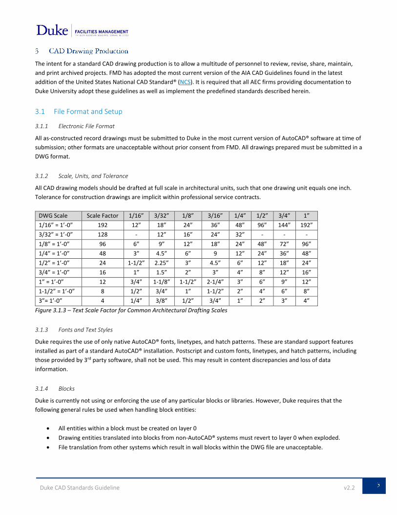
All CAD drawing models should be drafted at full scale in architectural units, such that one drawing unit equals one inch.
Tolerance for construction drawings are implicit within professional service contracts.
DWG Scale Scale Factor 1/16” 3/32” 1/8” 3/16” 1/4” 1/2” 3/4” 1”
1/16” = 1’-0” 192 12” 18” 24” 36” 48” 96” 144” 192”
3/32” = 1’-0” 128 - 12” 16” 24” 32” - - -
1/8” = 1’-0” 96 6” 9” 12” 18” 24” 48” 72” 96”
1/4” = 1’-0” 48 3” 4.5” 6” 9 12” 24” 36” 48”
1/2” = 1’-0” 24 1-1/2” 2.25” 3” 4.5” 6” 12” 18” 24”
3/4” = 1’-0” 16 1” 1.5” 2” 3” 4” 8” 12” 16”
1” = 1’-0” 12 3/4” 1-1/8” 1-1/2” 2-1/4” 3” 6” 9” 12”
1-1/2” = 1’-0” 8 1/2” 3/4” 1” 1-1/2” 2” 4” 6” 8”
3”= 1’-0” 4 1/4” 3/8” 1/2” 3/4” 1” 2” 3” 4”
Figure 3.1.3 – Text Scale Factor for Common Architectural Drafting Scales
3.1.3 Fonts and Text Styles
Duke requires the use of only native AutoCAD® fonts, linetypes, and hatch patterns. These are standard support features
installed as part of a standard AutoCAD® installation. Postscript and custom fonts, linetypes, and hatch patterns, including
those provided by 3rd party software, shall not be used. This may result in content discrepancies and loss of data
information.
3.1.4 Blocks
Duke is currently not using or enforcing the use of any particular blocks or libraries. However, Duke requires that the
following general rules be used when handling block entities:
All entities within a block must be created on layer 0
Drawing entities translated into blocks from non-AutoCAD® systems must revert to layer 0 when exploded.
File translation from other systems which result in wall blocks within the DWG file are unacceptable.
Duke CAD Standards Guideline v2.2
3.1.5 Standard Paper Sizes
In an effort to maintain consistency between record drawings, all submitted documents must be produced to the following
standard sizes: 24x36 (ARCH D) or 30x42 (ARCH E – preferred size).
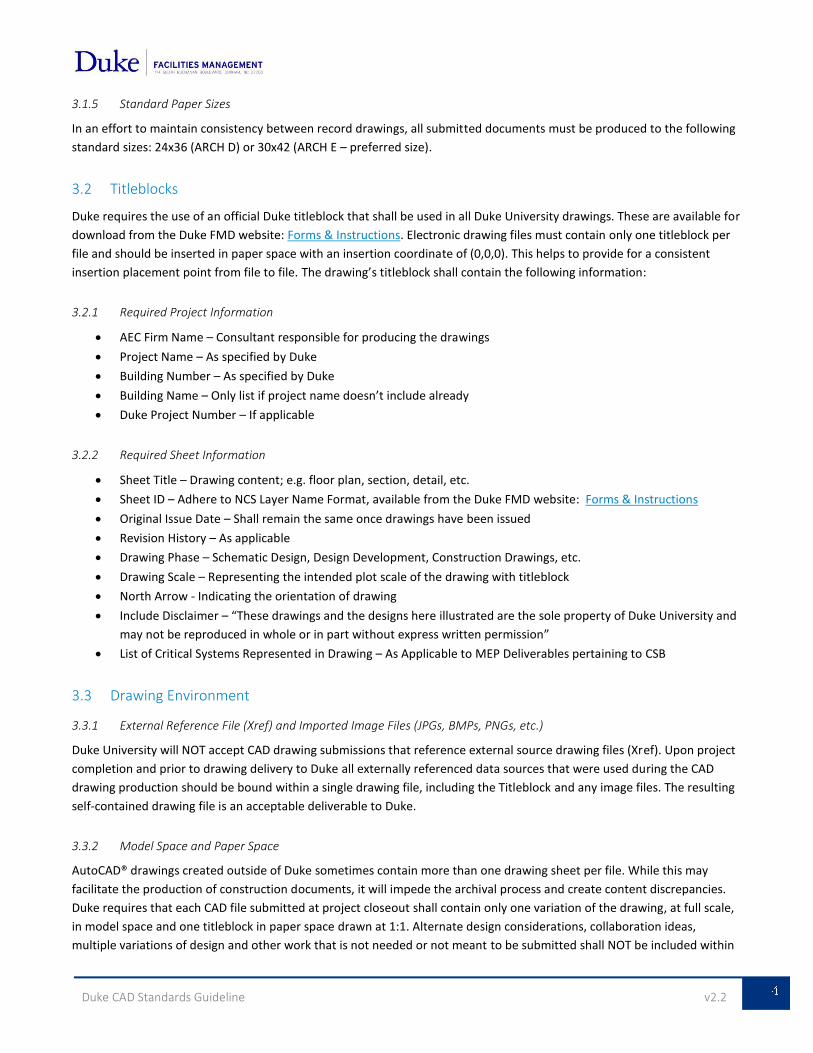
3.2 Titleblocks
Duke requires the use of an official Duke titleblock that shall be used in all Duke University drawings. These are available for
download from the Duke FMD website: Forms & Instructions. Electronic drawing files must contain only one titleblock per
file and should be inserted in paper space with an insertion coordinate of (0,0,0). This helps to provide for a consistent
insertion placement point from file to file. The drawing’s titleblock shall contain the following information:
3.2.1 Required Project Information
AEC Firm Name – Consultant responsible for producing the drawings
Project Name – As specified by Duke
Building Number – As specified by Duke
Building Name – Only list if project name doesn’t include already
Duke Project Number – If applicable
3.2.2 Required Sheet Information
Sheet Title – Drawing content; e.g. floor plan, section, detail, etc.
Sheet ID – Adhere to NCS Layer Name Format, available from the Duke FMD website: Forms & Instructions
Original Issue Date – Shall remain the same once drawings have been issued
Revision History – As applicable
Drawing Phase – Schematic Design, Design Development, Construction Drawings, etc.
Drawing Scale – Representing the intended plot scale of the drawing with titleblock
North Arrow - Indicating the orientation of drawing
Include Disclaimer – “These drawings and the designs here illustrated are the sole property of Duke University and
may not be reproduced in whole or in part without express written permission”
List of Critical Systems Represented in Drawing – As Applicable to MEP Deliverables pertaining to CSB
3.3 Drawing Environment
3.3.1 External Reference File (Xref) and Imported Image Files (JPGs, BMPs, PNGs, etc.)
Duke University will NOT accept CAD drawing submissions that reference external source drawing files (Xref). Upon project
completion and prior to drawing delivery to Duke all externally referenced data sources that were used during the CAD
drawing production should be bound within a single drawing file, including the Titleblock and any image files. The resulting
self-contained drawing file is an acceptable deliverable to Duke.
3.3.2 Model Space and Paper Space
AutoCAD® drawings created outside of Duke sometimes contain more than one drawing sheet per file. While this may
facilitate the production of construction documents, it will impede the archival process and create content discrepancies.
Duke requires that each CAD file submitted at project closeout shall contain only one variation of the drawing, at full scale,
in model space and one titleblock in paper space drawn at 1:1. Alternate design considerations, collaboration ideas,
multiple variations of design and other work that is not needed or not meant to be submitted shall NOT be included within
Duke CAD Standards Guideline v2.2
the file. All AutoCAD® drawings shall be purged of empty, unused, or nonessential drawing data prior to submittal. This
includes all unused layers, linetypes, blocks, fonts, and entities.
In addition, the following practices should NOT be followed:
Do not place or draw model related blocks, tags, and objects in paper space
Do not dimension model space objects in paper space
Do not rotate the User Coordinate System (UCS), i.e. XY plane
3.4 Layering
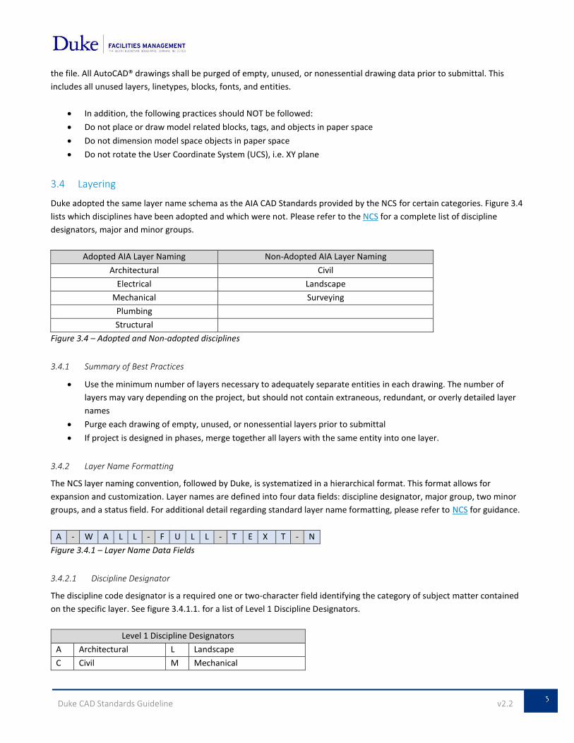
Duke adopted the same layer name schema as the AIA CAD Standards provided by the NCS for certain categories. Figure 3.4
lists which disciplines have been adopted and which were not. Please refer to the NCS for a complete list of discipline
designators, major and minor groups.
Adopted AIA Layer Naming Non-Adopted AIA Layer Naming
Architectural Civil
Electrical Landscape
Mechanical Surveying
Plumbing
Structural
Figure 3.4 – Adopted and Non-adopted disciplines
3.4.1 Summary of Best Practices
Use the minimum number of layers necessary to adequately separate entities in each drawing. The number of
layers may vary depending on the project, but should not contain extraneous, redundant, or overly detailed layer
names
Purge each drawing of empty, unused, or nonessential layers prior to submittal
If project is designed in phases, merge together all layers with the same entity into one layer.
3.4.2 Layer Name Formatting
The NCS layer naming convention, followed by Duke, is systematized in a hierarchical format. This format allows for
expansion and customization. Layer names are defined into four data fields: discipline designator, major group, two minor
groups, and a status field. For additional detail regarding standard layer name formatting, please refer to NCS for guidance.
A - W A L L - F U L L - T E X T - N
Figure 3.4.1 – Layer Name Data Fields
3.4.2.1 Discipline Designator
The discipline code designator is a required one or two-character field identifying the category of subject matter contained
on the specific layer. See figure 3.4.1.1. for a list of Level 1 Discipline Designators.
Level 1 Discipline Designators
A Architectural L Landscape
C Civil M Mechanical
Duke CAD Standards Guideline v2.2
E Electrical P Plumbing
G General S Structural
Figure 3.4.1.1 – Level 1 Discipline Designators
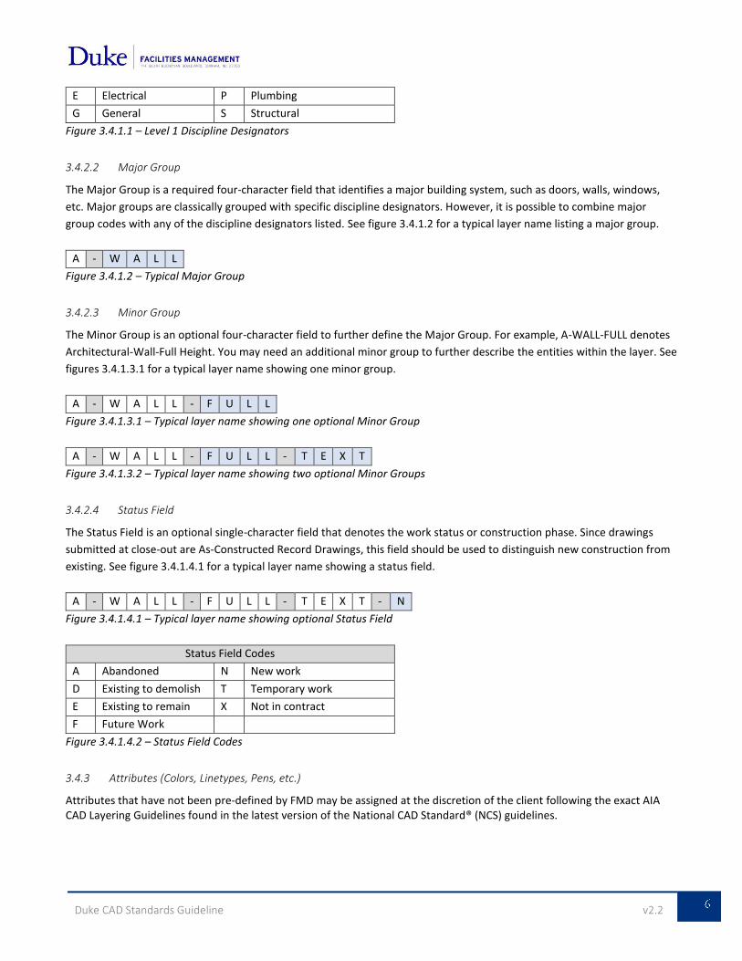
3.4.2.2 Major Group
The Major Group is a required four-character field that identifies a major building system, such as doors, walls, windows,
etc. Major groups are classically grouped with specific discipline designators. However, it is possible to combine major
group codes with any of the discipline designators listed. See figure 3.4.1.2 for a typical layer name listing a major group.
A - W A L L
Figure 3.4.1.2 – Typical Major Group
3.4.2.3 Minor Group
The Minor Group is an optional four-character field to further define the Major Group. For example, A-WALL-FULL denotes
Architectural-Wall-Full Height. You may need an additional minor group to further describe the entities within the layer. See
figures 3.4.1.3.1 for a typical layer name showing one minor group.
A - W A L L - F U L L
Figure 3.4.1.3.1 – Typical layer name showing one optional Minor Group
A - W A L L - F U L L - T E X T
Figure 3.4.1.3.2 – Typical layer name showing two optional Minor Groups
3.4.2.4 Status Field
The Status Field is an optional single-character field that denotes the work status or construction phase. Since drawings
submitted at close-out are As-Constructed Record Drawings, this field should be used to distinguish new construction from
existing. See figure 3.4.1.4.1 for a typical layer name showing a status field.
A - W A L L - F U L L - T E X T - N
Figure 3.4.1.4.1 – Typical layer name showing optional Status Field
Status Field Codes
A Abandoned N New work
D Existing to demolish T Temporary work
E Existing to remain X Not in contract
F Future Work
Figure 3.4.1.4.2 – Status Field Codes
3.4.3 Attributes (Colors, Linetypes, Pens, etc.)
Attributes that have not been pre-defined by FMD may be assigned at the discretion of the client following the exact AIA CAD Layering Guidelines found in the latest version of the National CAD Standard® (NCS) guidelines.
Duke CAD Standards Guideline v2.2
3.4.3.1 Colors
Duke recommends the use of specific colors for the layers and annotation layers most often used to assist in program assessment, space documentation and future project development. The color assignment of these layers can be found in the Standard Layer Listing, figure 3.4.4. All other layers may have their colors assigned at the discretion of the client.
3.4.3.2 Linetypes
The default linetype of each layer is typically CONTINUOUS unless otherwise specified. All other layers may have their
linetypes assigned at the discretion of the client.
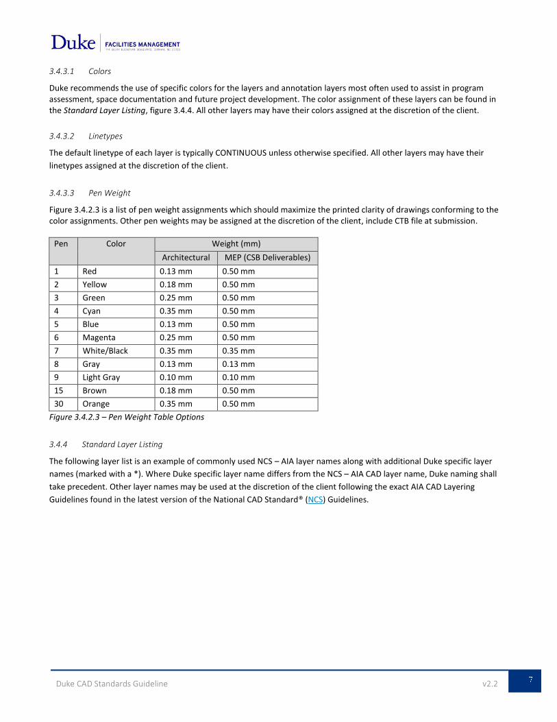
3.4.3.3 Pen Weight
Figure 3.4.2.3 is a list of pen weight assignments which should maximize the printed clarity of drawings conforming to the color assignments. Other pen weights may be assigned at the discretion of the client, include CTB file at submission.
Pen Color Weight (mm)
Architectural MEP (CSB Deliverables)
1 Red 0.13 mm 0.50 mm
2 Yellow 0.18 mm 0.50 mm
3 Green 0.25 mm 0.50 mm
4 Cyan 0.35 mm 0.50 mm
5 Blue 0.13 mm 0.50 mm
6 Magenta 0.25 mm 0.50 mm
7 White/Black 0.35 mm 0.35 mm
8 Gray 0.13 mm 0.13 mm
9 Light Gray 0.10 mm 0.10 mm
15 Brown 0.18 mm 0.50 mm
30 Orange 0.35 mm 0.50 mm
Figure 3.4.2.3 – Pen Weight Table Options
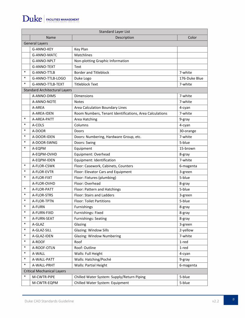
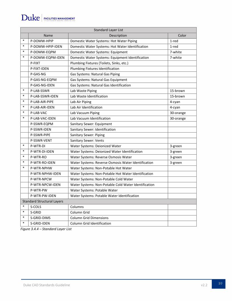
3.4.4 Standard Layer Listing
The following layer list is an example of commonly used NCS – AIA layer names along with additional Duke specific layer
names (marked with a *). Where Duke specific layer name differs from the NCS – AIA CAD layer name, Duke naming shall
take precedent. Other layer names may be used at the discretion of the client following the exact AIA CAD Layering
Guidelines found in the latest version of the National CAD Standard® (NCS) Guidelines.
Duke CAD Standards Guideline v2.2
Standard Layer List
Name Description Color
General Layers
G-ANNO-KEY Key Plan
G-ANNO-MATC Matchlines
G-ANNO-NPLT Non-plotting Graphic Information
G-ANNO-TEXT Text
* G-ANNO-TTLB Border and Titleblock 7-white
* G-ANNO-TTLB-LOGO Duke Logo 176-Duke Blue
* G-ANNO-TTLB-TEXT Titleblock Text 7-white
Standard Architectural Layers
A-ANNO-DIMS Dimensions 7-white
A-ANNO-NOTE Notes 7-white
A-AREA Area Calculation Boundary Lines 4-cyan
A-AREA-IDEN Room Numbers, Tenant Identifications, Area Calculations 7-white
* A-AREA-PATT Area Hatching 9-gray
* A-COLS Columns 4-cyan
* A-DOOR Doors 30-orange
* A-DOOR-IDEN Doors: Numbering, Hardware Group, etc. 7-white
* A-DOOR-SWNG Doors: Swing 5-blue
* A-EQPM Equipment 15-brown
A-EQPM-OVHD Equipment: Overhead 8-gray
A-EQPM-IDEN Equipment: Identification 7-white
* A-FLOR-CSWK Floor: Casework, Cabinets, Counters 6-magenta
* A-FLOR-EVTR Floor: Elevator Cars and Equipment 3-green
* A-FLOR-FIXT Floor: Fixtures (plumbing) 5-blue
A-FLOR-OVHD Floor: Overhead 8-gray
* A-FLOR-PATT Floor: Pattern and Hatchings 5-blue
* A-FLOR-STRS Floor: Stairs and Ladders 3-green
* A-FLOR-TPTN Floor: Toilet Partitions 5-blue
* A-FURN Furnishings 8-gray
* A-FURN-FIXD Furnishings: Fixed 8-gray
* A-FURN-SEAT Furnishings: Seating 8-gray
* A-GLAZ Glazing 3-green
* A-GLAZ-SILL Glazing: Window Sills 2-yellow
* A-GLAZ-IDEN Glazing: Window Numbering 7-white
* A-ROOF Roof 1-red
* A-ROOF-OTLN Roof: Outline 1-red
* A-WALL Walls: Full Height 4-cyan
* A-WALL-PATT Walls: Hatching/Poché 9-gray
* A-WALL-PRHT Walls: Partial Height 6-magenta
Critical Mechanical Layers
* M-CWTR-PIPE Chilled Water System: Supply/Return Piping 5-blue
M-CWTR-EQPM Chilled Water System: Equipment 5-blue
Duke CAD Standards Guideline v2.2
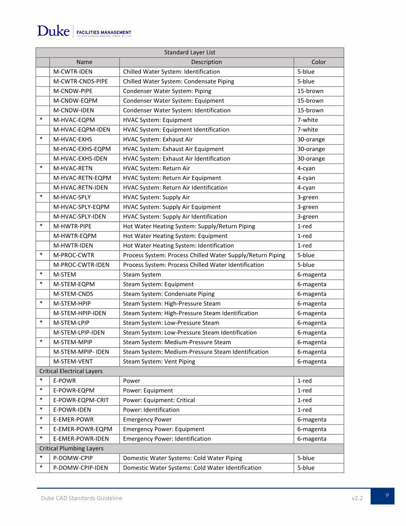
Standard Layer List
Name Description Color
M-CWTR-IDEN Chilled Water System: Identification 5-blue
M-CWTR-CNDS-PIPE Chilled Water System: Condensate Piping 5-blue
M-CNDW-PIPE Condenser Water System: Piping 15-brown
M-CNDW-EQPM Condenser Water System: Equipment 15-brown
M-CNDW-IDEN Condenser Water System: Identification 15-brown
* M-HVAC-EQPM HVAC System: Equipment 7-white
M-HVAC-EQPM-IDEN HVAC System: Equipment Identification 7-white
* M-HVAC-EXHS HVAC System: Exhaust Air 30-orange
M-HVAC-EXHS-EQPM HVAC System: Exhaust Air Equipment 30-orange
M-HVAC-EXHS-IDEN HVAC System: Exhaust Air Identification 30-orange
* M-HVAC-RETN HVAC System: Return Air 4-cyan
M-HVAC-RETN-EQPM HVAC System: Return Air Equipment 4-cyan
M-HVAC-RETN-IDEN HVAC System: Return Air Identification 4-cyan
* M-HVAC-SPLY HVAC System: Supply Air 3-green
M-HVAC-SPLY-EQPM HVAC System: Supply Air Equipment 3-green
M-HVAC-SPLY-IDEN HVAC System: Supply Air Identification 3-green
* M-HWTR-PIPE Hot Water Heating System: Supply/Return Piping 1-red
M-HWTR-EQPM Hot Water Heating System: Equipment 1-red
M-HWTR-IDEN Hot Water Heating System: Identification 1-red
* M-PROC-CWTR Process System: Process Chilled Water Supply/Return Piping 5-blue
M-PROC-CWTR-IDEN Process System: Process Chilled Water Identification 5-blue
* M-STEM Steam System 6-magenta
* M-STEM-EQPM Steam System: Equipment 6-magenta
M-STEM-CNDS Steam System: Condensate Piping 6-magenta
* M-STEM-HPIP Steam System: High-Pressure Steam 6-magenta
M-STEM-HPIP-IDEN Steam System: High-Pressure Steam Identification 6-magenta
* M-STEM-LPIP Steam System: Low-Pressure Steam 6-magenta
M-STEM-LPIP-IDEN Steam System: Low-Pressure Steam Identification 6-magenta
* M-STEM-MPIP Steam System: Medium-Pressure Steam 6-magenta
M-STEM-MPIP- IDEN Steam System: Medium-Pressure Steam Identification 6-magenta
M-STEM-VENT Steam System: Vent Piping 6-magenta
Critical Electrical Layers
* E-POWR Power 1-red
* E-POWR-EQPM Power: Equipment 1-red
* E-POWR-EQPM-CRIT Power: Equipment: Critical 1-red
* E-POWR-IDEN Power: Identification 1-red
* E-EMER-POWR Emergency Power 6-magenta
* E-EMER-POWR-EQPM Emergency Power: Equipment 6-magenta
* E-EMER-POWR-IDEN Emergency Power: Identification 6-magenta
Critical Plumbing Layers
* P-DOMW-CPIP Domestic Water Systems: Cold Water Piping 5-blue
* P-DOMW-CPIP-IDEN Domestic Water Systems: Cold Water Identification 5-blue
Duke CAD Standards Guideline v2.2
Standard Layer List
Name Description Color
* P-DOMW-HPIP Domestic Water Systems: Hot Water Piping 1-red
* P-DOMW-HPIP-IDEN Domestic Water Systems: Hot Water Identification 1-red
* P-DOMW-EQPM Domestic Water Systems: Equipment 7-white
* P-DOMW-EQPM-IDEN Domestic Water Systems: Equipment Identification 7-white
P-FIXT Plumbing Fixtures (Toilets, Sinks, etc.)
P-FIXT-IDEN Plumbing Fixtures Identification
P-GAS-NG Gas Systems: Natural Gas Piping
P-GAS-NG-EQPM Gas Systems: Natural Gas Equipment
P-GAS-NG-IDEN Gas Systems: Natural Gas Identification
* P-LAB-SSWR Lab Waste Piping 15-brown
* P-LAB-SSWR-IDEN Lab Waste Identification 15-brown
* P-LAB-AIR-PIPE Lab Air Piping 4-cyan
* P-LAB-AIR-IDEN Lab Air Identification 4-cyan
* P-LAB-VAC Lab Vacuum Piping 30-orange
* P-LAB-VAC-IDEN Lab Vacuum Identification 30-orange
P-SSWR-EQPM Sanitary Sewer: Equipment
P-SSWR-IDEN Sanitary Sewer: Identification
P-SSWR-PIPE Sanitary Sewer: Piping
P-SSWR-VENT Sanitary Sewer: Vents
* P-WTR-DI Water Systems: Deionized Water 3-green
* P-WTR-DI-IDEN Water Systems: Deionized Water Identification 3-green
* P-WTR-RO Water Systems: Reverse Osmosis Water 3-green
* P-WTR-RO-IDEN Water Systems: Reverse Osmosis Water Identification 3-green
* P-WTR-NPHW Water Systems: Non-Potable Hot Water
P-WTR-NPHW-IDEN Water Systems: Non-Potable Hot Water Identification
P-WTR-NPCW Water Systems: Non-Potable Cold Water
P-WTR-NPCW-IDEN Water Systems: Non-Potable Cold Water Identification
P-WTR-PW Water Systems: Potable Water
P-WTR-PW-IDEN Water Systems: Potable Water Identification
Standard Structural Layers
* S-COLS Columns
* S-GRID Column Grid
* S-GRID-DIMS Column Grid Dimensions
* S-GRID-IDEN Column Grid Identification
Figure 3.4.4 – Standard Layer List
Duke CAD Standards Guideline v2.2
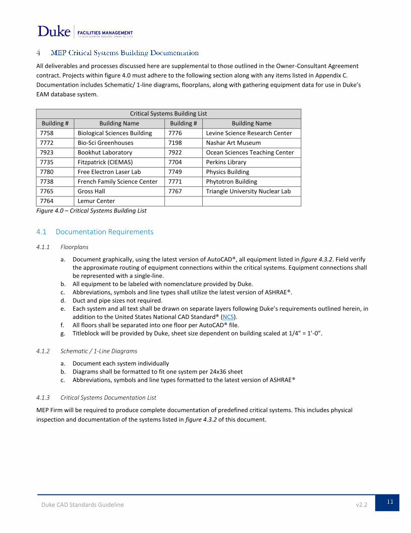
All deliverables and processes discussed here are supplemental to those outlined in the Owner-Consultant Agreement
contract. Projects within figure 4.0 must adhere to the following section along with any items listed in Appendix C.
Documentation includes Schematic/ 1-line diagrams, floorplans, along with gathering equipment data for use in Duke’s
EAM database system.
Critical Systems Building List
Building # Building Name Building # Building Name
7758 Biological Sciences Building 7776 Levine Science Research Center
7772 Bio-Sci Greenhouses 7198 Nashar Art Museum
7923 Bookhut Laboratory 7922 Ocean Sciences Teaching Center
7735 Fitzpatrick (CIEMAS) 7704 Perkins Library
7780 Free Electron Laser Lab 7749 Physics Building
7738 French Family Science Center 7771 Phytotron Building
7765 Gross Hall 7767 Triangle University Nuclear Lab
7764 Lemur Center
Figure 4.0 – Critical Systems Building List
4.1 Documentation Requirements
4.1.1 Floorplans
a. Document graphically, using the latest version of AutoCAD®, all equipment listed in figure 4.3.2. Field verify the approximate routing of equipment connections within the critical systems. Equipment connections shall be represented with a single-line.
b. All equipment to be labeled with nomenclature provided by Duke. c. Abbreviations, symbols and line types shall utilize the latest version of ASHRAE®. d. Duct and pipe sizes not required. e. Each system and all text shall be drawn on separate layers following Duke’s requirements outlined herein, in
addition to the United States National CAD Standard® (NCS). f. All floors shall be separated into one floor per AutoCAD® file. g. Titleblock will be provided by Duke, sheet size dependent on building scaled at 1/4” = 1’-0”.
4.1.2 Schematic / 1-Line Diagrams
a. Document each system individually b. Diagrams shall be formatted to fit one system per 24x36 sheet c. Abbreviations, symbols and line types formatted to the latest version of ASHRAE®
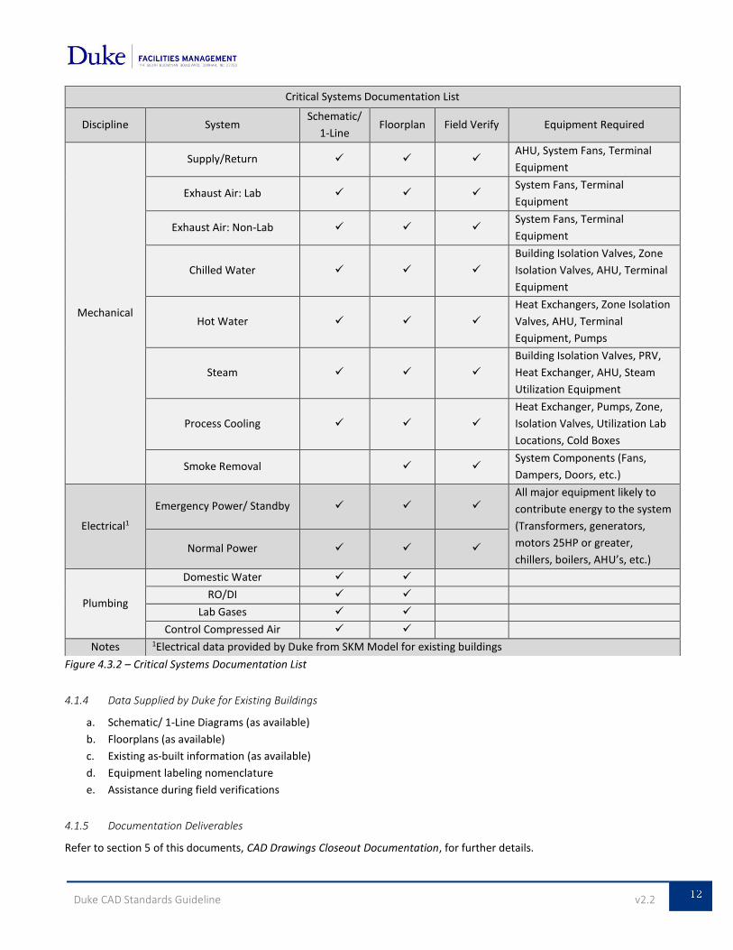
4.1.3 Critical Systems Documentation List
MEP Firm will be required to produce complete documentation of predefined critical systems. This includes physical
inspection and documentation of the systems listed in figure 4.3.2 of this document.
Duke CAD Standards Guideline v2.2
Figure 4.3.2 – Critical Systems Documentation List
4.1.4 Data Supplied by Duke for Existing Buildings
a. Schematic/ 1-Line Diagrams (as available)
b. Floorplans (as available)
c. Existing as-built information (as available)
d. Equipment labeling nomenclature
e. Assistance during field verifications
4.1.5 Documentation Deliverables
Refer to section 5 of this documents, CAD Drawings Closeout Documentation, for further details.
Critical Systems Documentation List
Discipline System Schematic/
1-Line Floorplan Field Verify Equipment Required
Mechanical
Supply/Return AHU, System Fans, Terminal
Equipment
Exhaust Air: Lab System Fans, Terminal
Equipment
Exhaust Air: Non-Lab System Fans, Terminal
Equipment
Chilled Water
Building Isolation Valves, Zone
Isolation Valves, AHU, Terminal
Equipment
Hot Water
Heat Exchangers, Zone Isolation
Valves, AHU, Terminal
Equipment, Pumps
Steam
Building Isolation Valves, PRV,
Heat Exchanger, AHU, Steam
Utilization Equipment
Process Cooling
Heat Exchanger, Pumps, Zone,
Isolation Valves, Utilization Lab
Locations, Cold Boxes
Smoke Removal System Components (Fans,
Dampers, Doors, etc.)
Electrical1
Emergency Power/ Standby All major equipment likely to
contribute energy to the system
(Transformers, generators,
motors 25HP or greater,
chillers, boilers, AHU’s, etc.) Normal Power
Plumbing
Domestic Water
RO/DI
Lab Gases
Control Compressed Air
Notes 1Electrical data provided by Duke from SKM Model for existing buildings
Duke CAD Standards Guideline v2.2
5.1 Translating from Other CAD Software
Duke acknowledges that many of its AEC firms do not use the same software to produce drawings and models for their
projects. However, Duke expects that service providers who work with other file formats submit DWG formatted CAD files
upon project closeout. These files must fully conform to the latest AIA CAD Guidelines obtained from the United States
National CAD Standard® (NCS) in addition to the Duke requirements outlined herein. These files shall have no significant
loss of drawing entities or project data that can result from standard CAD file translation procedures.
It is recommended that a thorough translation/conversion test procedure be conducted before the drawing development phase of the project. This test will identify file conversion issues early on and allow for corrective measures to be taken prior to the project closeout. All DWG files and CAD drawing entities submitted at the end of a project must be able to be manipulated using standard AutoCAD® drafting procedures. Non-compliance with this policy may result in the rejection of CAD files submitted at project closeout in addition to delayed final project payment.
5.2 Sheet Identification
5.2.1 File Identification and Naming Conventions
Duke requires that for each sheet submitted as project deliverable there is a corresponding DWG file. The sheet and the
digital files should follow the same naming convention as described in the latest version of the NCS® Drawing Set
Organization Standard. This is available for download from the Duke FMD website: Forms & Instructions.
5.2.2 Standard Sheet Identification
The sheet identifier consists of three components: the discipline designator, the sheet type designator, and the sheet
sequence number.
5.2.2.1 Discipline Designator
The discipline designator consists of one alphabetical character and a hyphen or two alphabetical characters. The
designator allows for the user to easily identify the category of subject matter contained within the file. Standard layer
codes used for the discipline designator are listed in section 3.4 - Layers of this document.
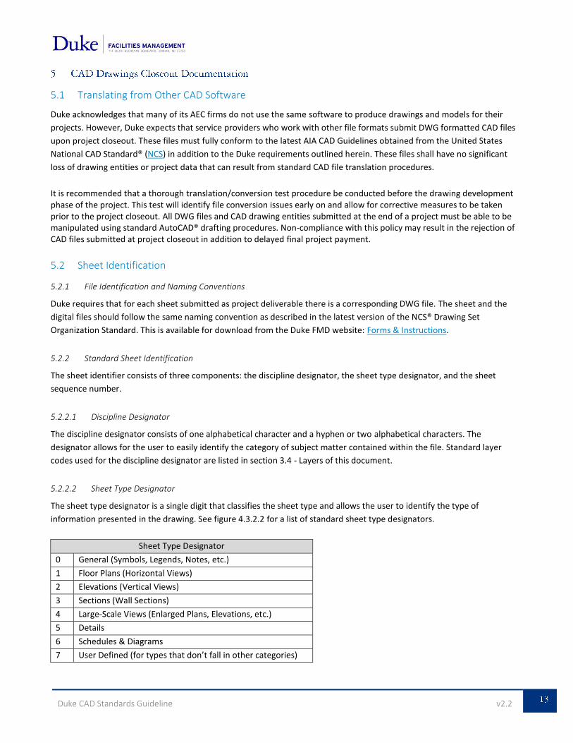
5.2.2.2 Sheet Type Designator
The sheet type designator is a single digit that classifies the sheet type and allows the user to identify the type of
information presented in the drawing. See figure 4.3.2.2 for a list of standard sheet type designators.
Sheet Type Designator
0 General (Symbols, Legends, Notes, etc.)
1 Floor Plans (Horizontal Views)
2 Elevations (Vertical Views)
3 Sections (Wall Sections)
4 Large-Scale Views (Enlarged Plans, Elevations, etc.)
5 Details
6 Schedules & Diagrams
7 User Defined (for types that don’t fall in other categories)
Duke CAD Standards Guideline v2.2
8 User Defined (for types that don’t fall in other categories)
9 3D Representations (Isometrics, Perspectives, Photographs)
Figure 4.3.2.2 – Sheet Type Designators
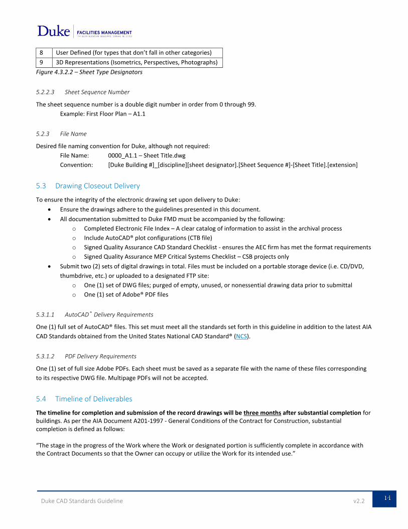
5.2.2.3 Sheet Sequence Number
The sheet sequence number is a double digit number in order from 0 through 99.
Example: First Floor Plan – A1.1
5.2.3 File Name
Desired file naming convention for Duke, although not required:
File Name: 0000_A1.1 – Sheet Title.dwg
Convention: [Duke Building #]_[discipline][sheet designator].[Sheet Sequence #]-[Sheet Title].[extension]
5.3 Drawing Closeout Delivery
To ensure the integrity of the electronic drawing set upon delivery to Duke:
Ensure the drawings adhere to the guidelines presented in this document.
All documentation submitted to Duke FMD must be accompanied by the following:
o Completed Electronic File Index – A clear catalog of information to assist in the archival process
o Include AutoCAD® plot configurations (CTB file)
o Signed Quality Assurance CAD Standard Checklist - ensures the AEC firm has met the format requirements
o Signed Quality Assurance MEP Critical Systems Checklist – CSB projects only
Submit two (2) sets of digital drawings in total. Files must be included on a portable storage device (i.e. CD/DVD,
thumbdrive, etc.) or uploaded to a designated FTP site:
o One (1) set of DWG files; purged of empty, unused, or nonessential drawing data prior to submittal
o One (1) set of Adobe® PDF files
5.3.1.1 AutoCAD® Delivery Requirements
One (1) full set of AutoCAD® files. This set must meet all the standards set forth in this guideline in addition to the latest AIA
CAD Standards obtained from the United States National CAD Standard® (NCS).
5.3.1.2 PDF Delivery Requirements
One (1) set of full size Adobe PDFs. Each sheet must be saved as a separate file with the name of these files corresponding
to its respective DWG file. Multipage PDFs will not be accepted.
5.4 Timeline of Deliverables
The timeline for completion and submission of the record drawings will be three months after substantial completion for buildings. As per the AIA Document A201-1997 - General Conditions of the Contract for Construction, substantial completion is defined as follows: “The stage in the progress of the Work where the Work or designated portion is sufficiently complete in accordance with the Contract Documents so that the Owner can occupy or utilize the Work for its intended use.”

Duke CAD Standards Guideline v2.2
A. ELECTRONIC FILE INDEX .............................................................................................................................................. A
B. QUALITY ASSURANCE CAD STANDARD CHECKLIST ....................................................................................................... B
C. QUALITY ASSURANCE MEP CRITICAL SYSTEMS CHECKLIST ........................................................................................... C
Duke CAD Standards Guideline v2.2
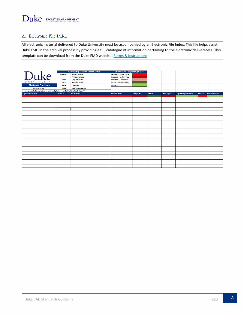
All electronic material delivered to Duke University must be accompanied by an Electronic File Index. This file helps assist
Duke FMD in the archival process by providing a full catalogue of information pertaining to the electronic deliverables. This
template can be download from the Duke FMD website: Forms & Instructions.
Duke CAD Standards Guideline v2.2
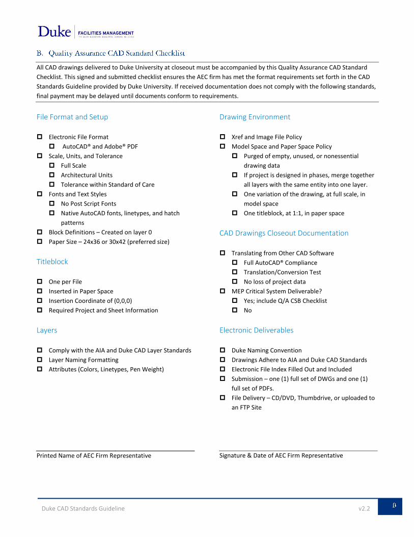
All CAD drawings delivered to Duke University at closeout must be accompanied by this Quality Assurance CAD Standard
Checklist. This signed and submitted checklist ensures the AEC firm has met the format requirements set forth in the CAD
Standards Guideline provided by Duke University. If received documentation does not comply with the following standards,
final payment may be delayed until documents conform to requirements.
File Format and Setup
Electronic File Format
AutoCAD® and Adobe® PDF
Scale, Units, and Tolerance
Full Scale
Architectural Units
Tolerance within Standard of Care
Fonts and Text Styles
No Post Script Fonts
Native AutoCAD fonts, linetypes, and hatch
patterns
Block Definitions – Created on layer 0
Paper Size – 24x36 or 30x42 (preferred size)
Titleblock
One per File
Inserted in Paper Space
Insertion Coordinate of (0,0,0)
Required Project and Sheet Information
Layers
Comply with the AIA and Duke CAD Layer Standards
Layer Naming Formatting
Attributes (Colors, Linetypes, Pen Weight)
Printed Name of AEC Firm Representative
Drawing Environment
Xref and Image File Policy
Model Space and Paper Space Policy
Purged of empty, unused, or nonessential
drawing data
If project is designed in phases, merge together
all layers with the same entity into one layer.
One variation of the drawing, at full scale, in
model space
One titleblock, at 1:1, in paper space
CAD Drawings Closeout Documentation
Translating from Other CAD Software
Full AutoCAD® Compliance
Translation/Conversion Test
No loss of project data
MEP Critical System Deliverable?
Yes; include Q/A CSB Checklist
No
Electronic Deliverables
Duke Naming Convention
Drawings Adhere to AIA and Duke CAD Standards
Electronic File Index Filled Out and Included
Submission – one (1) full set of DWGs and one (1)
full set of PDFs.
File Delivery – CD/DVD, Thumbdrive, or uploaded to
an FTP Site
Signature & Date of AEC Firm Representative
Duke CAD Standards Guideline v2.2
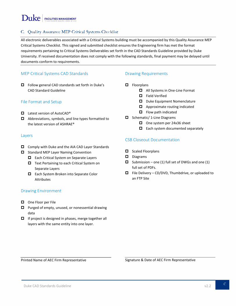
All electronic deliverables associated with a Critical Systems building must be accompanied by this Quality Assurance MEP
Critical Systems Checklist. This signed and submitted checklist ensures the Engineering firm has met the format
requirements pertaining to Critical Systems Deliverables set forth in the CAD Standards Guideline provided by Duke
University. If received documentation does not comply with the following standards, final payment may be delayed until
documents conform to requirements.
MEP Critical Systems CAD Standards
Follow general CAD standards set forth in Duke’s
CAD Standard Guideline
File Format and Setup
Latest version of AutoCAD®
Abbreviations, symbols, and line types formatted to
the latest version of ASHRAE®
Layers
Comply with Duke and the AIA CAD Layer Standards
Standard MEP Layer Naming Convention
Each Critical System on Separate Layers
Text Pertaining to each Critical System on
Separate Layers
Each System Broken into Separate Color
Attributes
Drawing Environment
One Floor per File
Purged of empty, unused, or nonessential drawing
data
If project is designed in phases, merge together all
layers with the same entity into one layer.
Printed Name of AEC Firm Representative
Drawing Requirements
Floorplans
All Systems in One-Line Format
Field Verified
Duke Equipment Nomenclature
Approximate routing indicated
Flow path indicated
Schematic/ 1-Line Diagrams
One system per 24x36 sheet
Each system documented separately
CSB Closeout Documentation
Scaled Floorplans
Diagrams
Submission – one (1) full set of DWGs and one (1)
full set of PDFs.
File Delivery – CD/DVD, Thumbdrive, or uploaded to
an FTP Site
Signature & Date of AEC Firm Representative


![[School] Magazine: Unused Images](https://img.pdfslide.us/doc/110x75/558e49c91a28ab75518b4747/school-magazine-unused-images.jpg)