Embed Size (px)
Citation preview
Barrel Mounted Ballistic Chronograph
V2 Ballistic Chronograph• Advanced strapping system• Recommended Barrel Diameters: 0.5"-2.0"• Muzzle Brakes up to: 2.5“ Dia x 3.0“ Length
Parts ListSpacer/Alignment GuideInstruction ManualTechnical SpecificationsTroubleshooting Guides
1
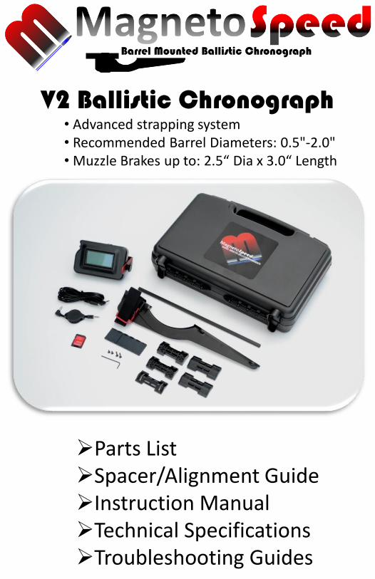
Parts List
2
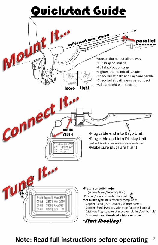
Quickstart Guide
MAKEFLUSH •Plug cable end into Bayo Unit
•Plug cable end into Display Unit (Unit will do a brief connection check on startup)
•Make sure plugs are flush!
•Loosen thumb nut all the way•Put strap on muzzle•Pull slack out of strap•Tighten thumb nut till secure•Check bullet path and Bayo are parallel•Check bullet path clears sensor deck•Adjust height with spacers
•Press in on switch (access Menu/Select Option)
•Push up/down on switch to scroll•Set Bullet-type (bullet/barrel compliance)
Copper+Lead (.223 -.458cal/sporter barrels)Copper+Steel (Any cal. with steel/sporter barrels)22/Shot/Slug (Lead or thin copper plating/bull barrels)Custom (Lower threshold = More sensitive)
•Start Shooting!
parallel
loose
Note: Read full instructions before operating
tight
3
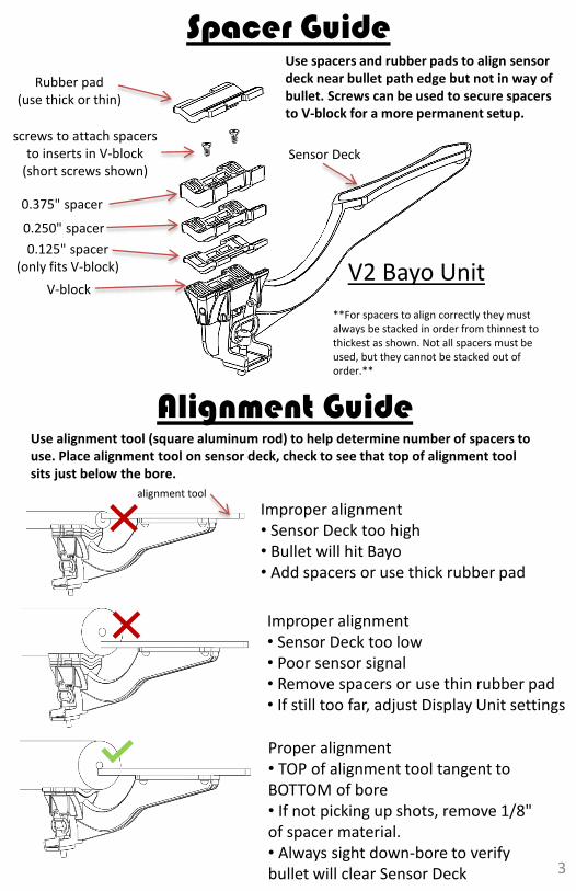
Spacer Guide
0.375" spacer
0.250" spacer
0.125" spacer(only fits V-block)
Rubber pad(use thick or thin)
screws to attach spacers to inserts in V-block
(short screws shown)
V-blockV2 Bayo Unit
Use spacers and rubber pads to align sensor deck near bullet path edge but not in way of bullet. Screws can be used to secure spacers to V-block for a more permanent setup.
Sensor Deck
Alignment GuideUse alignment tool (square aluminum rod) to help determine number of spacers to use. Place alignment tool on sensor deck, check to see that top of alignment tool sits just below the bore.
Improper alignment• Sensor Deck too high• Bullet will hit Bayo• Add spacers or use thick rubber pad
Improper alignment• Sensor Deck too low• Poor sensor signal• Remove spacers or use thin rubber pad• If still too far, adjust Display Unit settings
Proper alignment• TOP of alignment tool tangent to BOTTOM of bore• If not picking up shots, remove 1/8" of spacer material.• Always sight down-bore to verify bullet will clear Sensor Deck
**For spacers to align correctly they must always be stacked in order from thinnest to thickest as shown. Not all spacers must be used, but they cannot be stacked out of order.**
alignment tool
4
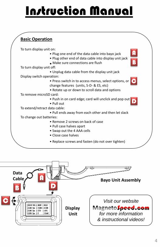
Data Cable
DisplayUnit
Visit our website
for more information
& instructional videos!
Basic Operation
To turn display unit on:• Plug one end of the data cable into bayo jack• Plug other end of data cable into display unit jack
•Make sure connections are flushTo turn display unit off:
• Unplug data cable from the display unit jackDisplay switch operation:
• Press switch in to access menus, select options, or change features (units, S-D- & ES, etc)• Rotate up or down to scroll data and options
To remove microSD card:• Push in on card edge; card will unclick and pop out• Pull out
To extend/retract data cable:• Pull ends away from each other and then let slack
To change out batteries:• Remove 2 screws on back of case• Pull case halves apart• Swap out the 4 AAA cells• Close case halves
• Replace screws and fasten (do not over tighten)
Bayo Unit Assembly
Instruction Manual
A
B
C
D
AB
C
D
5
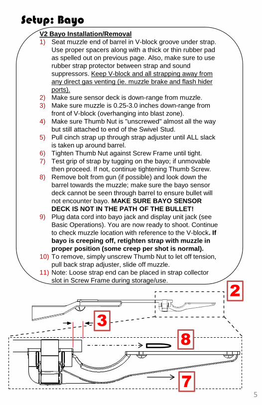
V2 Bayo Installation/Removal
1) Seat muzzle end of barrel in V-block groove under strap.
Use proper spacers along with a thick or thin rubber pad
as spelled out on previous page. Also, make sure to use
rubber strap protector between strap and sound
suppressors. Keep V-block and all strapping away from
any direct gas venting (ie. muzzle brake and flash hider
ports).
2) Make sure sensor deck is down-range from muzzle.
3) Make sure muzzle is 0.25-3.0 inches down-range from
front of V-block (overhanging into blast zone).
4) Make sure Thumb Nut is "unscrewed" almost all the way
but still attached to end of the Swivel Stud.
5) Pull cinch strap up through strap adjuster until ALL slack
is taken up around barrel.
6) Tighten Thumb Nut against Screw Frame until tight.
7) Test grip of strap by tugging on the bayo; if unmovable
then proceed. If not, continue tightening Thumb Screw.
8) Remove bolt from gun (if possible) and look down the
barrel towards the muzzle; make sure the bayo sensor
deck cannot be seen through barrel to ensure bullet will
not encounter bayo. MAKE SURE BAYO SENSOR
DECK IS NOT IN THE PATH OF THE BULLET!
9) Plug data cord into bayo jack and display unit jack (see
Basic Operations). You are now ready to shoot. Continue
to check muzzle location with reference to the V-block. If
bayo is creeping off, retighten strap with muzzle in
proper position (some creep per shot is normal).
10) To remove, simply unscrew Thumb Nut to let off tension,
pull back strap adjuster, slide off muzzle.
11) Note: Loose strap end can be placed in strap collector
slot in Screw Frame during storage/use.
Setup: Bayo
2
3
7
8
Sensor deck
Blast zone
Strap Collector
11
6
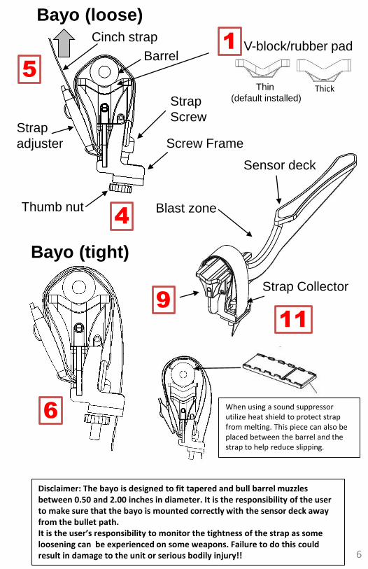
Disclaimer: The bayo is designed to fit tapered and bull barrel muzzles between 0.50 and 2.00 inches in diameter. It is the responsibility of the user to make sure that the bayo is mounted correctly with the sensor deck away from the bullet path. It is the user’s responsibility to monitor the tightness of the strap as some loosening can be experienced on some weapons. Failure to do this could result in damage to the unit or serious bodily injury!!
BarrelV-block/rubber pad
Strap
Screw
Bayo (loose)
Bayo (tight)
Strap
adjuster
Thin
(default installed)Thick
Cinch strap
4
5
9
1
Screw Frame
Thumb nut
6When using a sound suppressor utilize heat shield to protect strap from melting. This piece can also be placed between the barrel and the strap to help reduce slipping.
7
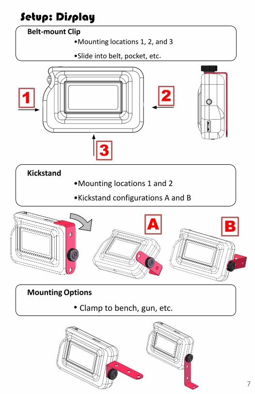
Setup: DisplayBelt-mount Clip
•Mounting locations 1, 2, and 3
•Slide into belt, pocket, etc.
11 2
3
2
3
Kickstand•Mounting locations 1 and 2
•Kickstand configurations A and B
A B
7
Mounting Options
• Clamp to bench, gun, etc.
8
Operation & Menus
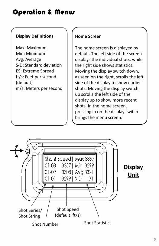
Display Definitions
Max: MaximumMin: MinimumAvg: AverageS-D: Standard deviationES: Extreme Spreadft/s: Feet per second(default)m/s: Meters per second
Home Screen
The home screen is displayed by default. The left side of the screen displays the individual shots, while the right side shows statistics. Moving the display switch down, as seen on the right, scrolls the left side of the display to show earlier shots. Moving the display switch up scrolls the left side of the display up to show more recent shots. In the home screen, pressing in on the display switchbrings the menu screen.
Shot Series/Shot String
Shot Number
Shot Speed(default: ft/s)
Shot Statistics
DisplayUnit
9
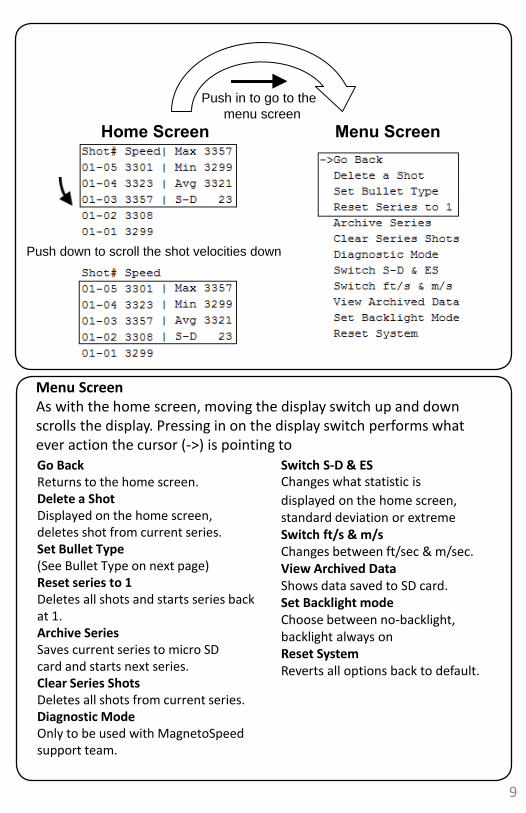
Home Screen Menu Screen
Push down to scroll the shot velocities down
Push in to go to the
menu screen
Menu ScreenAs with the home screen, moving the display switch up and down scrolls the display. Pressing in on the display switch performs what ever action the cursor (->) is pointing to
Changes what statistic is
displayed on the home screen,standard deviation or extremeSwitch ft/s & m/sChanges between ft/sec & m/sec.View Archived DataShows data saved to SD card.Set Backlight modeChoose between no-backlight,backlight always onReset SystemReverts all options back to default.
Switch S-D & ESGo BackReturns to the home screen. Delete a Shot Displayed on the home screen, deletes shot from current series. Set Bullet Type (See Bullet Type on next page) Reset series to 1 Deletes all shots and starts series back at 1. Archive SeriesSaves current series to micro SD card and starts next series. Clear Series ShotsDeletes all shots from current series. Diagnostic ModeOnly to be used with MagnetoSpeedsupport team.
10
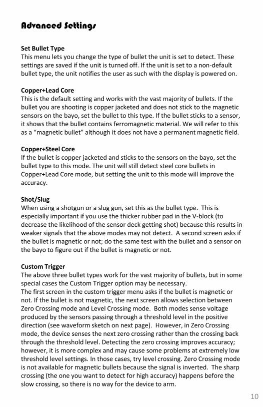
Advanced Settings
Set Bullet TypeThis menu lets you change the type of bullet the unit is set to detect. These settings are saved if the unit is turned off. If the unit is set to a non-default bullet type, the unit notifies the user as such with the display is powered on.
Copper+Lead CoreThis is the default setting and works with the vast majority of bullets. If the bullet you are shooting is copper jacketed and does not stick to the magnetic sensors on the bayo, set the bullet to this type. If the bullet sticks to a sensor, it shows that the bullet contains ferromagnetic material. We will refer to this as a “magnetic bullet” although it does not have a permanent magnetic field.
Copper+Steel CoreIf the bullet is copper jacketed and sticks to the sensors on the bayo, set the bullet type to this mode. The unit will still detect steel core bullets in Copper+Lead Core mode, but setting the unit to this mode will improve the accuracy.
Shot/SlugWhen using a shotgun or a slug gun, set this as the bullet type. This is especially important if you use the thicker rubber pad in the V-block (to decrease the likelihood of the sensor deck getting shot) because this results in weaker signals that the above modes may not detect. A second screen asks if the bullet is magnetic or not; do the same test with the bullet and a sensor on the bayo to figure out if the bullet is magnetic or not.
Custom Trigger The above three bullet types work for the vast majority of bullets, but in some special cases the Custom Trigger option may be necessary. The first screen in the custom trigger menu asks if the bullet is magnetic or not. If the bullet is not magnetic, the next screen allows selection between Zero Crossing mode and Level Crossing mode. Both modes sense voltage produced by the sensors passing through a threshold level in the positive direction (see waveform sketch on next page). However, in Zero Crossing mode, the device senses the next zero crossing rather than the crossing back through the threshold level. Detecting the zero crossing improves accuracy; however, it is more complex and may cause some problems at extremely low threshold level settings. In those cases, try level crossing. Zero Crossing mode is not available for magnetic bullets because the signal is inverted. The sharp crossing (the one you want to detect for high accuracy) happens before the slow crossing, so there is no way for the device to arm.
11
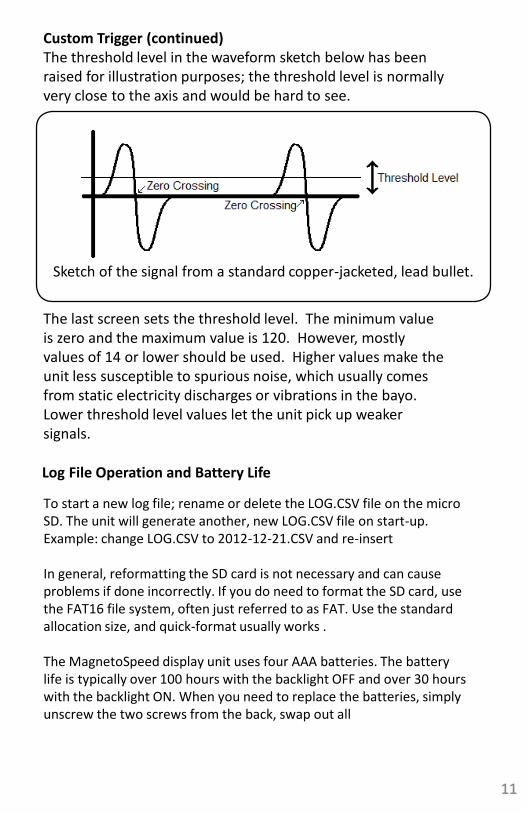
Custom Trigger (continued)The threshold level in the waveform sketch below has been raised for illustration purposes; the threshold level is normally very close to the axis and would be hard to see.
Sketch of the signal from a standard copper-jacketed, lead bullet.
The last screen sets the threshold level. The minimum value is zero and the maximum value is 120. However, mostly values of 14 or lower should be used. Higher values make the unit less susceptible to spurious noise, which usually comes from static electricity discharges or vibrations in the bayo. Lower threshold level values let the unit pick up weaker signals.
11
Log File Operation and Battery Life
To start a new log file; rename or delete the LOG.CSV file on the micro SD. The unit will generate another, new LOG.CSV file on start-up. Example: change LOG.CSV to 2012-12-21.CSV and re-insert
In general, reformatting the SD card is not necessary and can cause problems if done incorrectly. If you do need to format the SD card, use the FAT16 file system, often just referred to as FAT. Use the standard allocation size, and quick-format usually works .
The MagnetoSpeed display unit uses four AAA batteries. The battery life is typically over 100 hours with the backlight OFF and over 30 hours with the backlight ON. When you need to replace the batteries, simply unscrew the two screws from the back, swap out all
Troubleshooting Guide
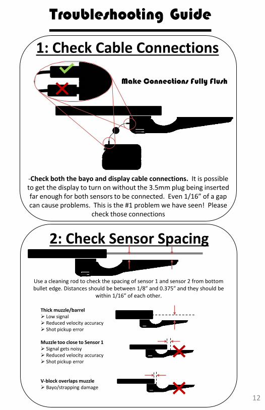
1: Check Cable Connections
Make Connections Fully Flush
-Check both the bayo and display cable connections. It is possible to get the display to turn on without the 3.5mm plug being inserted far enough for both sensors to be connected. Even 1/16” of a gap can cause problems. This is the #1 problem we have seen! Please
check those connections
2: Check Sensor Spacing
Thick muzzle/barrel Low signal Reduced velocity accuracy Shot pickup error
Muzzle too close to Sensor 1 Signal gets noisy Reduced velocity accuracy Shot pickup error
V-block overlaps muzzle Bayo/strapping damage
Use a cleaning rod to check the spacing of sensor 1 and sensor 2 from bottom bullet edge. Distances should be between 1/8” and 0.375” and they should be
within 1/16” of each other.
12
13
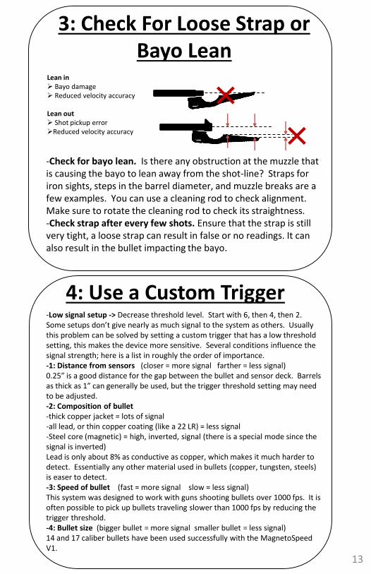
4: Use a Custom Trigger-Low signal setup -> Decrease threshold level. Start with 6, then 4, then 2. Some setups don’t give nearly as much signal to the system as others. Usually this problem can be solved by setting a custom trigger that has a low threshold setting, this makes the device more sensitive. Several conditions influence the signal strength; here is a list in roughly the order of importance.-1: Distance from sensors (closer = more signal farther = less signal) 0.25” is a good distance for the gap between the bullet and sensor deck. Barrels as thick as 1” can generally be used, but the trigger threshold setting may need to be adjusted.-2: Composition of bullet -thick copper jacket = lots of signal -all lead, or thin copper coating (like a 22 LR) = less signal -Steel core (magnetic) = high, inverted, signal (there is a special mode since the signal is inverted)Lead is only about 8% as conductive as copper, which makes it much harder to detect. Essentially any other material used in bullets (copper, tungsten, steels) is easer to detect. -3: Speed of bullet (fast = more signal slow = less signal)This system was designed to work with guns shooting bullets over 1000 fps. It is often possible to pick up bullets traveling slower than 1000 fps by reducing the trigger threshold. -4: Bullet size (bigger bullet = more signal smaller bullet = less signal)14 and 17 caliber bullets have been used successfully with the MagnetoSpeedV1.
3: Check For Loose Strap or Bayo Lean
Lean in Bayo damage Reduced velocity accuracy
Lean out Shot pickup errorReduced velocity accuracy
-Check for bayo lean. Is there any obstruction at the muzzle that is causing the bayo to lean away from the shot-line? Straps for iron sights, steps in the barrel diameter, and muzzle breaks are a few examples. You can use a cleaning rod to check alignment. Make sure to rotate the cleaning rod to check its straightness. -Check strap after every few shots. Ensure that the strap is still very tight, a loose strap can result in false or no readings. It can also result in the bullet impacting the bayo.
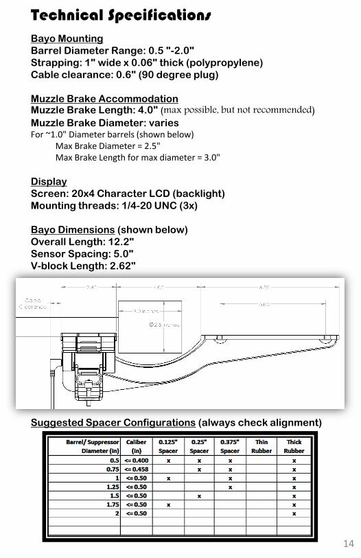
Bayo Mounting
Barrel Diameter Range: 0.5 "-2.0"
Strapping: 1" wide x 0.06" thick (polypropylene)
Cable clearance: 0.6" (90 degree plug)
Muzzle Brake AccommodationMuzzle Brake Length: 4.0" (max possible, but not recommended)Muzzle Brake Diameter: variesFor ~1.0" Diameter barrels (shown below)
Max Brake Diameter = 2.5"Max Brake Length for max diameter = 3.0"
Display
Screen: 20x4 Character LCD (backlight)
Mounting threads: 1/4-20 UNC (3x)
Bayo Dimensions (shown below)
Overall Length: 12.2"
Sensor Spacing: 5.0"
V-block Length: 2.62"
Suggested Spacer Configurations (always check alignment)
14
Technical Specifications

Magnetospeed, LLC
9206 Rod Rd, Suite C
Austin, Texas 78736
(512) 284-8161
www.MagnetoSpeed.com
Made in USA
Patent Pending

![Watch Diagram . . . . . . . . . . . . . . . . . . . . . . . . . . . . . . . . . . 3...The CHRONOGRAPH will continue running if you switch to a different mode. CHRONOGRAPH [CHRON] 8](https://img.pdfslide.us/doc/110x75/610090c3059fde73bd0a665e/watch-diagram-.jpg)