Embed Size (px)
Citation preview


V1.1 Creation on Jan13th2012
King‐Golden Limited
CONTENTS
1. Reventon ESC Features ……………………………………………………………………………..Page1
2. Specifications…………………………………………………………………………………………….Page1 3. ESC’s indicating LEDs………………………………………………………………………………….Page6 4. Wiring Diagram………………………………………………………………………………………….Page7 5. Throttle Range Setting/Calibration……………………………………………………………..Page8 6. The LED Status in Normal Running……………………………………………………………...Page8 7. Protection Function …………………………………………………………………………………...Page8 8. Trouble Shooting………………………………………………………………………………………….Page9 9. Optional Upgrade Accessories…………………………………………………………………….Page10 10. Programming the ESC ………………………………………………………………………………..Page10 11. Program Stock Club Race ESC……………………………………………………………………..Page13 12. Programmable Items list……………………………………………………………………………..Page14 13. ESC Product Warranty Period………………………………………………………………….….Page23
Reventon Series Brushless Motor Speed Controller Manual Thank you for purchasing the Speed Passion REVENTON series electronic speed controller (ESC). High power systems for RC models can be very dangerous. Users should read this manual carefully. Speed Passion has no control over the correct use, installation, application, or maintenance of our products. No liability shall be assumed nor accepted for any damages, losses or costs resulting from the use of the product. Any claims arising from the failure of the ESC, malfunctioning etc. will be denied. Speed Passion assumes no liability for personal injury or consequential damages resulting from our products or our workmanship. As far as is legally permitted, the obligation to compensation is limited to the invoiced amount of the affected product.
1. Reventon ESC Features: The Reventon ESC is suitable for 1/10th scale on road and off road vehicles.
◆ Compatible with all sensored and sensorless brushless motors.
◆ Built in ESC enhancement feature will allow users to update to the latest DRRS Version 3.0 software and any future software developments.
◆ New “Reventon ‐ Dynamic Sensor Technology Series” feature. State of the art, new development in software will give users maximum efficiency along with a wide power band for consistent performance and maximum power output!
◆ Proportional ABS brake function with 9 steps of brake adjustment. 9 steps of Auto drag‐brake adjustment.
◆ New Digital Racing Response modes Version 2.0 (From Level 1 ‐ Smooth to Level 9 ‐ Aggressive) “Digital Racing Response System – DRRS3.0” (note 1). Fully upgradeable for different modes and levels of tuning.
◆ Multiple safety protection features: Low voltage cut‐off protection for lithium batteries / Over‐heat protection / Throttle signal loss protection / Locked motor protection.
◆ New “Dynamic Multi Timing System ‐ DMTS” To maximize motor and ESC performance, the Reventon ESC has a special 8 mode adjustment system designed for any brand of brushless motor.
◆ 3 running modes (Forward with brake “ No Reverse”, Forward with brake “reverse after FULL Stop” and Direct Forward/reverse with brake) (note 2).
◆ Four buttons for easy programming. Compatible with pocket‐sized USB SMART ESC program unit.
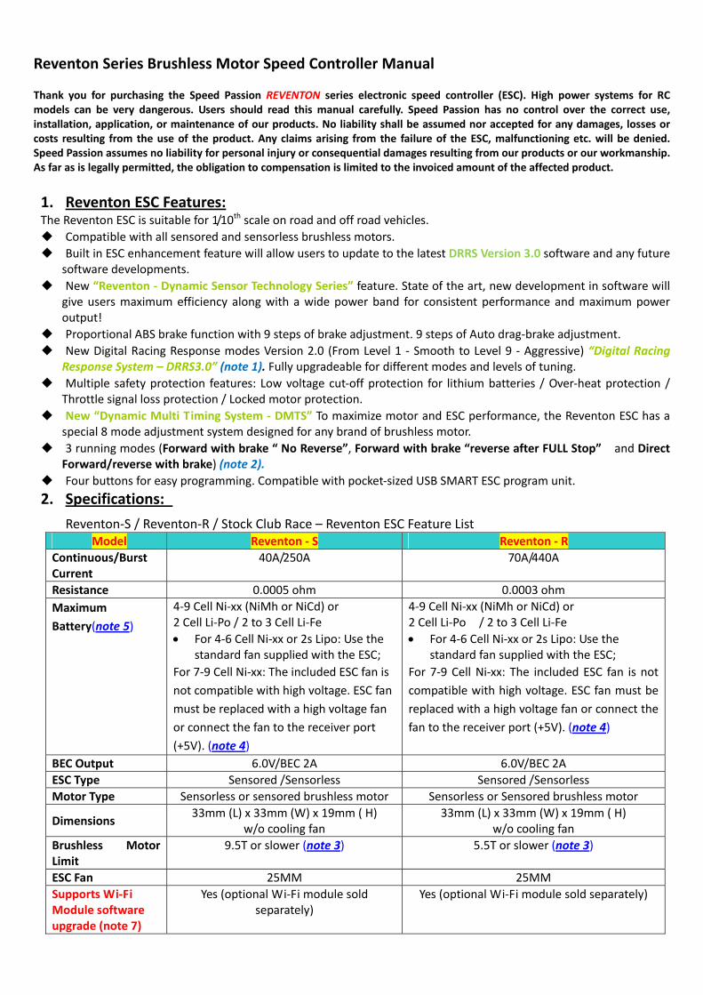
2. Specifications:
Reventon‐S / Reventon‐R / Stock Club Race – Reventon ESC Feature List Model Reventon ‐ S Reventon ‐ R
Continuous/Burst Current
40A/250A 70A/440A
Resistance 0.0005 ohm 0.0003 ohm
Maximum
Battery(note 5)
4‐9 Cell Ni‐xx (NiMh or NiCd) or 2 Cell Li‐Po / 2 to 3 Cell Li‐Fe
For 4‐6 Cell Ni‐xx or 2s Lipo: Use the standard fan supplied with the ESC;
For 7‐9 Cell Ni‐xx: The included ESC fan is
not compatible with high voltage. ESC fan
must be replaced with a high voltage fan
or connect the fan to the receiver port
(+5V). (note 4)
4‐9 Cell Ni‐xx (NiMh or NiCd) or 2 Cell Li‐Po / 2 to 3 Cell Li‐Fe
For 4‐6 Cell Ni‐xx or 2s Lipo: Use the standard fan supplied with the ESC;
For 7‐9 Cell Ni‐xx: The included ESC fan is not
compatible with high voltage. ESC fan must be
replaced with a high voltage fan or connect the
fan to the receiver port (+5V). (note 4)
BEC Output 6.0V/BEC 2A 6.0V/BEC 2A
ESC Type Sensored /Sensorless Sensored /Sensorless
Motor Type Sensorless or sensored brushless motor Sensorless or Sensored brushless motor
Dimensions 33mm (L) x 33mm (W) x 19mm ( H)
w/o cooling fan 33mm (L) x 33mm (W) x 19mm ( H)
w/o cooling fan
Brushless Motor Limit
9.5T or slower (note 3) 5.5T or slower (note 3)
ESC Fan 25MM 25MM
Supports Wi‐Fi Module software upgrade (note 7)
Yes (optional Wi‐Fi module sold separately)
Yes (optional Wi‐Fi module sold separately)

V1.1 Creation on Jan13th2012
King‐Golden Limited Page 1
Supports Smart LED program card with USB software upgrade
Yes Yes
Supports 2.4G held‐set for program setting
Yes (optional 2.4G held‐set programmer sold separately)
Yes (optional 2.4G held‐set programmer sold separately)
Supports Bluetooth module software upgrade (note 6)
Yes (optional Bluetooth module sold separately)
Yes (optional Bluetooth module sold separately)
Temperature display (note 2,8)
Yes Yes
Battery voltage display (note 2,9)
Yes Yes
Racing Profile Settings
Drift 1, Modified 0, Modified 1, Rock
Crawler, and Stock 0.
Drift1, Modified 0, Modified 1, Rock Crawler,
Stock 0, and Stock 1.
Note 1: For Reventon version, New Digital Racing Respond System (From Level 1 ‐ smooth to Level 9 ‐ aggressive) “Digital Racing Response System – DRRS3.0”.
Note 2: LED program card, Bluetooth module, or Wi‐Fi module are required to display the temperature of the ESC.
Model Reventon – Stock Club Race
Continuous/Burst Current 40A/250A
Resistance 0.0005 ohm
Battery(note 5) 4‐9 Cell Ni‐xx (NiMh or NiCd) or 2 Cell Li‐Po / 2 to 3 Cell Li‐Fe
For 4‐6 Cell Ni‐xx or 2s Lipo: Use the standard fan supplied with the ESC;
For 7‐9 Cell Ni‐xx: The included ESC fan is not compatible with
high voltage. ESC fan must be replaced with a high voltage fan or
connect the fan to the receiver port (+5V). (note 4)
BEC Output 6.0V/BEC 2A
ESC Type Sensored /Sensorless
Motor Type Sensorless or sensored brushless motor
Dimension 33mm (L) x 33mm (W) x 19mm ( H)
w/o cooling fan
Brushless Motor Limit Max > 8.5T (note 3)
ESC Fan 25MM
Supports Wi‐Fi Module software setting (note 10) Yes (optional Wi‐Fi module sold separately)
Supports Smart LED program card for program setting (note 12)
Yes (optional device) Note: Smart LED program card sold separately
Supports 2.4G held‐set for program setting No
Supports Bluetooth module setting (note 11) Yes (optional Bluetooth module sold separately)
Temperature display (note 2,8) Yes
Battery voltage display (note 2,9) Yes
Racing Profile setting Stock 0 – “Zero Timing Software”

V1.1 Creation on Jan13th2012
King‐Golden Limited Page 2
Note 3: The brushless motor limit is tested under the following conditions: a) The input is a 6 cell Ni‐xx battery; b) The ESC is equipped with a fan. Note 4: The voltage of fan socket on the ESC is equal to the voltage of the battery. It is directly
supplied without any regulation. Please keep in mind that the voltage of battery CANNOT exceed the voltage limit of the fan, 7.2V.
Note 5: For brushless motors, the ESC supports up to 8 cell NiMh/NiCd (or 3 cells Li‐Fe) input. Note 6: For Reventon R and S version, The ESC supports the Bluetooth module. The user can modify
the ESC settings by using a smart phone. Furthermore, users can download the latest firmware and updates for the ESC.
Wi‐Fi Module Bluetooth Module Note 7: For Reventon R and S version, The ESC supports the Wi‐Fi module. The user can modify the
ESC settings by using a smart phone. Furthermore, users can download the latest firmware and updates for the ESC.
Note 8: The display of battery voltage is for reference only. Note 9: The display of temperature is for reference only. Note 10: For Stock Club Race version, The ESC supports the Bluetooth module. The user can modify
the RC car setting by your Android phone / Tablet, “Android OS2.2 above”. Note 11: For Stock Club Race version, The ESC supports the Wi‐Fi module. The user can modify the RC
setting by your iPhone / iPad / iPod touch iOS 4.1 above. Note 12: For Stock Club Race version, The ESC supports the LED program card. The user can only use
the LED program card to change the setting. It will not connect to PC or alter the racing software profiles.

V1.1 Creation on Jan13th2012
King‐Golden Limited Page 3
Table 1: Racing firmware feature listing for REVENTON ESC
Item Description Drift1 Rock Crawler Modify1 Modify0 Stock0 Stock1
Running mode √ √ √ √ √ √
Forward with brake " No reverse" √ √ √ √ √ √
Forward /reverse with brake √ √ NA √ NA √
Forward with reverse NA √ NA NA NA NA
Forward with reverse after " FULL STOP" NA √ NA NA NA NA
Threshold Voltage/Cell LiPo Cut-off √ √ √ √ √ √
Dynamic Multi Timing System - DMTS 3.0 (Boost Timing) √ √ √ √ NA √
Digital Racing Response System-DDRS 3.0 √ √ √ √ √ √
Percentage Braking-ABS √ √ √ √ √ √
Percentage Drag Braking √ √ √ √ √ √
Throttle Percent Reverse √ √ √ √ √ √
Neutral Range √ √ √ √ √ √
Over Heat Protection √ √ √ √ √ √
Motor rotation (CW/CCW) NA NA NA NA NA NA
Supercharger slope Rate NA NA NA NA NA √
Supercharger Timing NA NA NA NA NA √
Boost Start RPM NA NA NA NA NA √
Supercharger Delay NA NA NA NA NA √
Boost Timing Acceleration NA NA NA NA NA √
ESC Temperature √ √ √ √ √ √
Battery Voltage √ √ √ √ √ √
ESC Firmware √ √ √ √ √ √

V1.1 Creation on Jan13th2012
King‐Golden Limited Page 4
3. ESC’s indicating LEDs:
*When the ESC is connected to the battery and turned on, the ESC can automatically identify the motor
type (Sensored/Sensorless) via the indicator LED.
*If the ESC is in Sensored mode, remove the sensor wire and the ESC will automatically change to
Sensorless mode.
Sensored/Sensorless ESC’s indicator LED
Status INDICATOR LED Status of the LED
Low battery voltage Red LED Blinking
Over‐heating of ESC and motor
(95℃) Yellow LED Blinking
Sensored motor Red and Yellow LED ON
Sensorless motor Yellow LED ON
Sensorless ESC’s Indicating LED
Function Indicating LED LED Status
Low battery voltage Red LED Blinking
Over‐heating of ESC and motor
(95℃) Yellow LED Blinking
Sensorless motor Yellow LED ON
Using the Reventon ESC
4. Wiring Diagram:
4.1 Connect the ESC, motor, receiver, battery and servo according to the diagram below. Positive “+” and Negative “‐” wires on the ESC are connected to the respective positive and negative terminals on the battery pack. Motor wires A, B and C are to be connected to respective terminals on the motor. The “SET” button is used for programming the ESC. The “Fan” connector is used to supply the cooling fan. The receiver cable of the ESC (black, red and white colored wires) is connected to the throttle channel of the receiver (Usually CH2). NOTE: The Capacitor MUST be connected to the Positive (+) and Negative (‐) terminals of the ESC. DAMAGE WILL OCCUR IF THE CAPACITOR IS NOT CONNECTED!

V1.1 Creation on Jan13th2012
King‐Golden Limited Page 5
Picture A: Wiring with a brushless motor
4.2 Brushless Motor Wiring Connecting to a sensored brushless motor
When using a sensored motor, it is necessary to connect the sensor cable to the “SENSOR” socket on the ESC and the sensor port on the motor. The ESC can automatically identify the motor type (sensored or sensorless) by detecting the signal coming from the SENSOR socket. WARNING! When using a sensored brushless motor, the A, B, C wires of the ESC MUST connect with the motor wire A, B, C respectively. Do not change the wire sequence!
Connecting to a sensorless brushless motor When using a brushless motor without a Hall Sensor, the #A, #B, #C wires of the ESC can be connected with the motor wires in any order. If the motor runs backwards, swap any two of the motor wire connections.
5. Throttle Range Setting/Calibration In order for the ESC to recognize the transmitter throttle range, the ESC must be calibrated it. The ESC must be calibrated when setting up a new ESC, using a new transmitter, or change the ATV or EPA settings of the radio. The ESC must be calibrated after each firmware update or the ESC will not work properly. There are 3 points that need to be set, “full throttle”,”full brake” and the neutral point. The following pictures show how to set the throttle range with a FutabaTM transmitter.

V1.1 Creation on Jan13th2012
King‐Golden Limited Page 6
6. The LED Status in Normal Running In normal use, if the throttle is at the neutral setting and the sensor cable is connected, the red LED and
the yellow LED will be lit. The red LED lights up and will flash when the ESC senses a low input voltage. The yellow LED lights up and will flash when the ESC overheating (over 95℃).
Alert signal 6.1 Abnormal input voltage alert tone:
The ESC checks the input voltage when powered on. If it is out of the normal range, the red LED will begin flashing.
7. Protection Function 7.1 Low voltage cut‐off protection:
7.1.1 If the lithium battery pack’s voltage is lower than the voltage threshold for 2 seconds, the ESC will cut power output. Please note that the ESC cannot be restarted if the voltage of each lithium cell is lower than 3.5V. Users can disable cutoff voltage protection function for competitive racing. 7.1.2 For NiMh/NiCd battery packs, if the voltage of the NiMh/NiCd battery pack is higher than 12V, it will be recognized as a 4 cell lithium battery pack. If it is higher than 9.0V, but lower than 12V, it will be recognized as a 3 cell lithium battery pack. If it is lower than 9.0V, it will be recognized as a 2 cell lithium battery pack. For example, a NiMh battery pack measuring 8.0V and the voltage threshold is set to 2.6V/Cell will be recognized as a 2 cell lithium battery pack. The low voltage cut‐off for this NiMh battery pack will be 2.6V x 2=5.2V.
7.2 Over‐heat protection: When the temperature of the ESC is over 95℃ for 5 seconds, the ESC will
cut power output. Users can disable over‐heat protection function for competitive racing. 7.3 Throttle signal loss protection: The ESC will cut power output if the throttle signal is lost for 0.2
second.
A) Ensure the ESC is switched off. Turn on the transmitter.
B) Set the direction of throttle channel to”REV” (ONLY for Futaba Radios), set the “EPA/ATV” value of throttle channel to “100%”.
C) Use a pen or screwdriver to press and hold the “SET” button and then switch on the ESC. Release the “SET” key when the red LED begins to flash.
D) Set the 3 points according to the steps shown in the picture to the left a) Neutral point b) Full throttle c) Full brake
E) When the calibration process is completed, the motor can be started after 3 seconds
(Please refer to the figures to the left)

V1.1 Creation on Jan13th2012
King‐Golden Limited Page 7
8. Trouble Shooting
Always start troubleshooting by resetting the ESC to the throttle range of the transmitter. Calibration will most likely solve the issue. (Throttle range calibration above)
9. Optional Upgrade Accessories Speed Passion provides the following accessories to upgrade
the Reventon ESC: 9.1 Heat sink fan (8V): The 8V fan is necessary when using
battery packs that are more than 6 cell NiMh/NiCd or 2s Lipo. It is mounted to the heat sink of the ESC. It helps to cool the ESC with downward airflow. The picture on the right side shows the installation.
Trouble Possible Reason Solution
After ESC is powered on, motor doesn’t work, no sound is emitted
The connections between battery pack and ESC are not correct
Check the power connections Replace the connectors
After ESC is powered on, motor won’t work, but emits “beep‐beep‐, beep‐beep‐” alert tone. (Every “beep‐beep‐” has a time interval of 1 second )
Input voltage is abnormal, too high or too low.
Check the voltage of the battery pack
After ESC is powered on, motor won’t work, but emits “beep‐, beep‐, beep‐” alert tone. (Every “beep‐” has a time interval of about 2 seconds)
Throttle signal is abnormal Check the transmitter and the receiver Check the wire of the throttle channel
The motor runs in the opposite direction
The wire connections between ESC and the motor need to be changed
Swap any two wire connections between the ESC and the motor.(Attention: This method only applies to sensorless motors)
The motor suddenly stops running while in working state
The throttle signal is lost Check transmitter and the receiverCheck the throttle channel polarity Recalibrate the ESC to the transmitter
The ESC has entered the Low Voltage Protection Mode
Replace the battery pack
Random stop or restart or irregular working state
Some connections are not reliable
Check all the connections: battery pack connections, throttle signal wire, and motor connections, etc. Reset ESC throttle range to transmitter
There is strong Electro ‐ Magnetic interference field.
Reset the ESC to resume normal operation. If the function does not resume, user may need to move to another area to operate the car.

V1.1 Creation on Jan13th2012
King‐Golden Limited Page 8
WARNING! Please note, the fan included with the ESC can ONLY work with a 2 cell lithium battery pack or 4‐6 cell NiMh / NiCd battery pack. Do not operate at higher voltages, otherwise it will be destroyed. Please check the label of the fan to confirm its working voltage before using it.
9.2 Low resistance, High capacity filtering capacitors. 9.3 Multi Smart Program Card.
10. Programming the ESC The Smart Program card is an optional accessory which may be purchased separately. Programming the ESC is easy and fast with the pocket sized device. To change settings, plug the receiver wire from the ESC into the socket of the program card (the socket is on the right corner, and marked with ). Turn on the ESC, each item’s value will be shown on the program card. Use “ITEM” and “VALUE” buttons to select the programmable items and new values, and press the “OK” button to send the new settings to the ESC.
10.1 ESC PC Program Method and update ESC software:
The Speed Passion Program Card is used to make all the adjustments to the active profile in the ESC. Any
active profile can be modified via PC software with.
10.1.1 Connect the Speed Passion Smart Program Card to the Reventon ESC.
10.1.2 Insert the Speed Passion CD‐ROM into the PC or Laptop computer.
10.1.3 Install Reventon PC interface software.
10.1.4 Install Reventon PC interface USB driver. (see Page 16 about steps of install the USB driver)
10.1.5 Connect the PC and Speed passion Smart Program Card by the USB Cable.
+-
V1.1 Creation on Jan13th2012
King‐Golden Limited Page 9
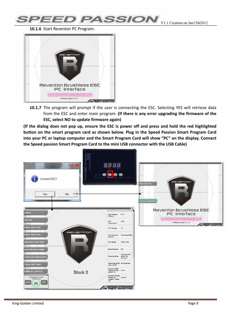
10.1.6 Start Reventon PC Program.
10.1.7 The program will prompt if the user is connecting the ESC. Selecting YES will retrieve data
from the ESC and enter main program. (If there is any error upgrading the firmware of the
ESC, select NO to update firmware again)
(If the dialog does not pop up, ensure the ESC is power off and press and hold the red highlighted
button on the smart program card as shown below. Plug in the Speed Passion Smart Program Card
into your PC or laptop computer and the Smart Program Card will show “PC” on the display. Connect
the Speed passion Smart Program Card to the mini USB connector with the USB Cable)

V1.1 Creation on Jan13th2012
King‐Golden Limited Page 10
10.1.8 Speed Passion Software Connection status icons should now be both GREEN.
10.1.9 The Speed Passion software is now installed and ready for use.
10.1.10 Please refer to the section above for general overview and field specific help.
10.1.11 Take a moment to review the selectable functions and read the specific help text for each to become
familiar with the programmable function. To make configuration changes to a function, select the
setting, then select from the drop down menu the new choice or option. When finished with the
configuration, click the “SEND Settings” button located on the bottom of each tabbed page to send
the settings to the ESC.
Connection: This is displayed on every Tab. There are two icons; one for the USB/PC connection, the other
indicates the ESC/Program Card connection. They are RED in color when disconnected and GREEN when connected.
Exemption Clause:
Speed Passion does not have control over the proper installation or use of this product therefore no liability
for any damages incurred in its use will be accepted. Operation of this product is at the user’s risk. The use
of radio control models requires a degree of skill. If you are a beginner please consult the advice of an
experienced user to prevent injury to goods or other persons.
Caution:
1) Do not operate the ESC at voltages lower than 6.0V or higher the 8.4V battery, damage to the ESC can
result.
2) When mounting the brushless motor to the car, pay careful attention to the length of the motor screws.
Screws must not exceed 4.0mm in depth. Any longer than this and internal damage to the motor will
result which will void the product warranty.
3) Ensure all connections are secure before using this product.

V1.1 Creation on Jan13th2012
King‐Golden Limited Page 11
11. Program Stock Club Race ESC
Note:
In the program process, the motor will emit “Beep” tones at the same time as the LED is flashes.
Ensure ESC is off. Turn on the transmitter.
Orange LED flashes for N times
Red LED flashes
Enter the corresponding programmable item, the RED LED flashes for several times, the times present the current value of this item
Press the SET key to choose the programmable value , the RED LED flashes for several times, the times presents the serial number of the value you are choosing
■The following steps are just like the above steps
Orange LED flashes for 3 times
Orange LED flashes for 2 times
Orange LED flashes for 1 time
Hold the SET key, Switch on the ESC
Red LED flashes 1 time, choose "Level 1" Red LED flashes 2 times, choose "Level 2" Red LED flashes 3 times, choose "Level 3" Red LED flashes 4 times, choose " Level 4" Red LED flashes 5 times, choose " Level 5" Red LED flashes 6 times, choose " Level 6” Red LED flashes 7 times, choose " Level 7" Red LED flashes 8 times, choose " Level 8” Red LED flashes 9 times, choose " Level 9”
Red LED flashes 1 time, choose "2.6V" Red LED flashes 2 times, choose "2.8V" Red LED flashes 3 times, choose "3.0V" Red LED flashes 4 times, choose "3.2V" Red LED flashes 5 times, choose "3.4V" Red LED flashes 6 times, choose "None"
Enter the 1st item "Running Mode"
Red LED flashes for 1 time to choose "Forward with brake
" Red LED flashes for 2 times to choose " Forward / Reverse with brake"
Enter the 3rd item "DDRS3.0"
Enter the 2nd item '”V/Cell Li Po Cut Off"
Press SET key to choose the value, the flash times of RED LED means the serial number of the value (1 time means the 1st value, 2 times means the 2nd value...)
Enter the Nth item
Release SET key
Hold SET key for 3 seconds
Hold SET key for 3 seconds
Hold SET key for 3 seconds
Release SET key
Press SET key
Press SET key
Press SET key
Press SET key
Release SET key
Release SET key
Finish P
rogramm
ing, switch off the E
SC
, and then switch it on

V1.1 Creation on Jan13th2012
King‐Golden Limited Page 12
12. Programmable Items list 12.1 Programmable Items list just for Reventon (Modified version)
Attention: The bold texts in the below form are the default settings.
Programmable Items
Programmable Value
1 2 3 4 5 6 7 8 9 10 11
Basic Item
1. Running mode
Forward with
brake "No
reverse"
2. Threshold V / Cell Li Po Cut off
2.6V /Cell
2.8V /Cell
3.0V /Cell
3.2V /Cell
3.4V /Cell
No protect
ion
3. Dynamic Multi Timing System - DMTS 3.0
0° 3.75° 7.5° 11.25° 15° 18.75° 22.5° 26.5°
4. Digital Racing Response System - DRRS 3 0
Level 1 Level
2 Level 3 Level 4 Level 5 Level 6 Level 7 Level 8 Level 9
Advanced Item
5. Percentage Braking - ABS
0% 10% 20% 30% 40% 50% 60% 70% 80% 90% 100%
6. Percent Drag Brake
0% 10% 20% 30% 40% 50% 60% 70% 80%
7. Throttle Percent Reverse
20% 30% 40% 50% 60% 70% 80% 90% 100%
8. Neutral Range
2% 4% 6% 8% 10% 12%
9. Over Heat Protection
Enable "95 °C
Cut off"
Disable
Special Item
10.ESC Temperature
11.Battery Voltage
12. ESC Firmware

V1.1 Creation on Jan13th2012
King‐Golden Limited Page 13
12.2 Limited Programmable Items list just for Reventon STOCK CLUB RACE
Note: Without full understanding of a specific function and its reason, it is not recommended that users
make changes to the “default” configuration. Defaults settings have been selected as a direct result of
testing. Users are at their own risk changing configurations.
Programmable Items
Programmable Value
1 2 3 4 5 6 7 8 9 10 11
Basic Item
1. Running mode
Forward with
brake "No
reverse"
2. Threshold V / Cell Li Po Cut off
2.6V /Cell
2.8V /Cell
3.0V /Cell
3.2V /Cell
3.4V /Cell
No protec
tion
3. Digital Racing Response System - DRRS 3 0
Level 1 Level 2
Level 3
Level 4
Level 5
Level 6
Level 7
Level 8
Level 9
Advanced Item
4. Percentage Braking - ABS
0% 10% 20% 30% 40% 50% 60% 70% 80% 90% 100%
5. Percent Drag Brake
0% 10% 20% 30% 40% 50% 60% 70% 80%
6. Neutral Range
2% 4% 6% 8% 10% 12%
7. Over Heat Protection
Enable "95 °C
Cut
Disable
Special Item
8. ESC Temperature
9. Battery Voltage
10. ESC Firmware

V1.1 Creation on Jan13th2012
King‐Golden Limited Page 14
12.3 Install USB driver:
For Windows 7 / Vista 1. Open SpUsbDriver folder.
3. Press “Install” button to start.
4. USB driver will install automatically.
5. If security warning pops up, click on “Install this driver software anyway.”
6. Click ok to finish driver installation.
2. Double click SpUsbInstaller.exe to install

V1.1 Creation on Jan13th2012
King‐Golden Limited Page 15
For Windows XP 1. Open SpUsbDriver folder.
2. Press “Install” button to start.
3. USB driver will install automatically.
4. Restart computer.
5. Connect PC and program card by USB cable.
6. Select “No, not this time”, then click “Next>” button.
7. Select “Install the software automatically (Recommended)”, then click “Next>” button.
.
2. Double click SpUsbInstaller.exe to install usb driver

V1.1 Creation on Jan13th2012
King‐Golden Limited Page 16
8. Click “Continue Anyway”
9. Click “Finish” to finish the installation.
12.4 Updating Program Card Firmware: 1. Install Speed Passion Reventon PC Interface on the PC. 2. Plug in the mini USB cable to the program card.
3. Pressing and hold the RESET button while plugging in the other end of the USB cable to the PC.
4. The program card will be display “- - - - “. Release the RESET button and launch the “Speed Passion Reventon PC
Interface” program.

V1.1 Creation on Jan13th2012
King‐Golden Limited Page 17
5. Click the button – “UPDATE FIRMWARE”
6. Select “LED_Reventon_V1.0.pgd” and click OK.
7. Click “Yes” to start the update.
8. The process time is around 1 minute. The Speed Passion Reventon PC Interface program will show a process bar to display
the status of the update firmware.
9. When the firmware update is complete, a message box will pop up confirming completion. Close the Speed Passion
Reventon PC Interface program and unplug the USB cable from the program card to finish the update. If the pop up box
does not display “Download Success”, please repeat the process again from step 2. Ensure the selection of the firmware is
correct. Selecting the LCD firmware instead of LED to update the program card will cause the update to be unsuccessful.
V1.1 Creation on Jan13th2012
King‐Golden Limited Page 18
12.5 Threshold V/cell Lipo cut off
12.5.1 Customize Voltage Cutoff selectable cutoff voltage of 2.6V/cell, 2.8V/cell, 3.0V/cell, 3.2V/cell, 3.4V/cell and No Protection.
According to the type of batteries, set up of the type of the batteries and Low Voltage Cutoff Threshold is programmed via PC software or program card. The ESC can detect the Voltage of the battery at any time and will cut output once the Voltage of the battery is lower than the preset Low Voltage Cutoff Threshold.
12.5.2 Running Mode: Forward with Brake “No reverse” mode: Forward and brake, but reverse is disabled. This mode is suitable for
competition.
Forward with Brake, Reverse after complete stop mode: Forward and brake, but reverse is enabled. This mode enables the reverse function, which is suitable for practice. Note: “Forward/Reverse with Brake” mode uses a “double‐tap” method to engage reverse. The ESC begins to brake and the motor reduces speed, but it will not engage reverse. When the throttle is moved back to neutral and quickly back to brake, reverse will engage as long as the car has stopped. At any time in the process of braking or reversing, if forward throttle is applied, the motor will respond immediately.
Forward / Reverse with brake – This is only to determine if reverse is to be enabled or not.
In racing, most tracks will not allow racing with reverse enabled.
Note: There is automatic protection built within the Speed Passion ESC. Only after the vehicle has stopped and
the trigger has returned to neutral will reverse become available. If while traveling in reverse, pull the trigger
to go forward. This is to prevent serious damage to the drive train.
12.5.3 “Dynamic Multi Timing System – DMTS 3.0”:
Users can select a timing system of 0~, 3.75~, 3.75~, 7.5~, 11.25~, 15~, 18.75~, 22.5~, 26.5~ This parameter is only available for brushless motors. There are many differences among styles and parameters of different brushless motors, so a fixed timing ESC is not ideal for all brushless motors. If it is necessary to make changes to the timing value, please select the most suitable timing value according to the motor you are using. Generally, higher timing value brings out higher power output, but at the expense of excess motor heat. Note: ESC timing advance adds with any physical advance already used on the motor itself. If the ESC value is 11.25, and you have 5.0 set on the motor, the total advance will be 16.25. Please note that the “timing” value will be available for both sensored and sensorless brushless motors.
12.5.4 “Digital Racing Response System – DRRS3.0” Digital Racing Mode:
Users can select the response system of Level 1, Level 2 Level, 3, Level 4, Level 5, Level 6, Level 7, Level 8, Level 9
Select from “smooth” to “aggressive” response system as required. The higher the level, the more punch and more aggressive the throttle response. Please note that if you choose “Level 9”, a good quality battery pack with high discharge ability is recommended, otherwise the levels will not give the effect expected.
12.5.5 Throttle Percent Reverse Force: Sets how much power will be applied in the reverse direction.
12.5.6 Percentage Braking‐ABS: The ESC provides a proportional brake function. Braking force is related to the position of the throttle stick. Maximum brake force refers to the ESC braking force when the throttle stick is located at the top point of the braking zone. A large brake force value can shorten the brake time, but it may damage gears.
12.5.7 Percent Drag Brake: Sets the amount of drag brake applied at neutral throttle to simulate a slight braking
effect of a neutral brushed motor while coasting.
12.5.8 Over Heat Protection: If the function is activated, the power output will be cut‐off when the temperature of the ESC or the internal temperature of the motor reaches 95ºC for more than 5 seconds. When the protection engages, the power to the motor will be cut off.

V1.1 Creation on Jan13th2012
King‐Golden Limited Page 19
12.5.9 Radio Neutral Range: (Dead band) Please see the illustration below to adjust the neutral range.
At any time when the throttle is located in neutral zone (except in throttle calibration or parameters program process), hold the “SET” key for 3 seconds and the red LED and yellow LED will flash at the same time. This will set each programmable item to its default value.
13.ESC Product Warranty Period:
Product Warranty:
Please see the full warranty terms and procedures on www.SpeedPassion.net for your country and
product before returning any product. User accepts all resulting liability. We reserve the right to modify
warranty provisions without notice. Warranty does not cover incorrect installation, components worn by
use, or any damage caused by crash, flooding or natural disaster. The company has no control over the
installation of this product; no liability may be assumed nor will be accepted for any damage resulting
from the use of this product.
Dear customer:
Thank you for purchasing one of the many Speed Passion R/C products. Please complete the below online
product registration for your recent purchase. If you are not already a Speed Passion member, please
complete the new member registration process before registering your new Speed Passion product. After
the completion of this process, our system will e‐mail you within the next 24 hours to confirm your product
registration and activate your products warranty. In the event you require warranty service, your product
registration information will be available from the www.speedpassion.net website allowing you to submit
your warranty item to any of our service centers located near you.
In addition, registered Speed Passion members will receive product notices, including notification of the
warranty expiration date of your Speed Passion products. Some Speed Passion products will be eligible for
an extended warranty service allowing Speed Passion members to enable additional protection of your
Speed Passion products.
# This product Registration will not suitable for Japan, Thailand, Malaysia and Singapore
* Thailand Motors and Speed Controllers (ESC) Warranty 7 Days only;
Japan Motors 30days and Speed Controllers (ESC) Warranty 90 Days only
http://www.speedpassion.net/news/newsDetails.asp?n=168