Embed Size (px)
Citation preview

2 www.proval.net
Cata
log
ue
2018
applications due to their light weight, low pressure loss, 100% leak free operation, easy and economic automation capabilities.
Beside the soft seat applications, development of PTFE seats and metal seats of double eccentric
are used from basic water applications to indus-trial applications and highly corrosive severe service applications
in water, sea water, steel, food, paper, chemical, petrochemical and all HVAC and general industri-
• Flow indication marked, ISO standard valve rotating shaft
• According to ISO 5211 direct mount ISO pad
• EN1092 PN10, PN16 ANSI 125/150 and BS10 Table-D,
• Wide range of seat solutions for all industrial applications
• -ment of valve during installation.
• Upper stem bushing
• PTFE / Bronzee bushing provides low torque and longer seat life by centering the disc and avoids leakage from stem due to non-centric rotation
• Easy removable, anti blow-out plate
• Tag plate with all valve material and useage data incuding valve Seriesal number
• Long neck for easy insulation
• PTFE / Bronzee bushing provides low torque and longer seat life by centering the disc andavoids leakage from stem due to non-centric rotation
• Integral o-ring system on seat avoid the leakage from stem
• 2 Pc shaft construction
rates (kv) and lower pressure loss in pipeline.
• Special groove on body
operation and improves the life cycle of seat
• O-ring to ensure 100%leak free operation
• Easy removable lower cap provides easy dismantling of the valve to replace any defected parts on maintenance • Heat No for easy tracing and QC

3www.dorukendustri.com
Ca
talo
gu
e 2018
V101 (Wafer) / V102 (Lug) Series DN25-600 Butterfly Valves Material List
Design Standard
EN 558 Series 20 (DIN3202-K1)
ISO5752 Series 20
API609 Table 1
BS5155 Series 4
Flange DrillingEN1092 PN 6/10/16
ANSI B 16.5 Class 150
Mounting Flange ISO5211
Testing Standard
EN12266-1/2
ISO5208, Category 3
API 598 Table 5
ANSI B16-104, Class VI
Pressure Rating Max 16 bar
Differential Pressure ∆p 16 bar
Vacuum Max 0.2 bar absolute pressure
Pressure - Temperature Diagram
DNDisc Angle-Openness (%)
10° 20° 30° 40° 50° 60° 70° 80° 90°
50 0,1 4,3 10 21 39 55 78 108 116
65 0,2 6,9 17 32 56 85 125 176 190
80 0,3 10 19 34 61 100 158 238 261
100 0,4 15 31 68 120 199 315 472 519
125 0,7 25 53 115 205 339 536 804 884
150 1,7 39 82 177 317 523 828 1243 1365
200 2,6 77 162 353 629 1039 1646 2468 2713
250 3,7 131 276 600 1070 1771 2802 4203 4619
300 4,3 202 428 927 1653 2735 4329 6494 7136
350 5,2 292 618 1339 2388 3951 6254 9380 10308
400 6,9 401 850 1842 3284 5434 8599 12899 14176
450 9,5 532 1126 2441 4349 7197 11390 17085 18774
500 12 684 1448 3138 5592 9253 14645 21967 24140
600 19 1057 2238 4848 8640 14296 22626 33939 37295
700 31 1568 3148 5740 8650 12930 19695 30186 42817
800 44 2064 4144 7557 11927 17830 27156 41621 59036
900 52 2613 5244 9563 15137 22564 34367 52674 74714
1000 73 3618 7262 13240 20897 31283 47648 73028 103583
1200 153 7598 15195 20020 43886 65695 100060 10146 217525
Kv values given in the table below,show the volume of water in m³/h atroom temperature that will pass through a given valve opening with apressure drop of Δp 1 bar .Butterfly Valves offer flow characteristics close to linear at angles ofopening between 30º and 90º .Recommended maximum velocity of flow for Butterfly Valves is 1.5 m/s.
General Design and Manufacturing Standards
V101 / V102 / V103 Series Butterfly Valves Flow Coefficient Kv Values
• PTFE / Bronzee bushing provides low torque and longer seat life by centering the disc and avoids leakage from stem due to non-centric rotation
• Heat No for easy tracing and QC
AISI316 / Duplex Stainless Steel Disc
AISI316 Mirror Polished St. Steel Disc
PFA Coated AISI316 Stainless Steel Disc
C958 Nickel-Alu-Bronze Disc
Rilsan (Nylon11) Coated GGG40 Disc

4 www.proval.net
Ca
talo
gu
e 2018
• Available in sizes from DN50 to DN300 .• Tongue and groove design,field-replaceable resilient rubber seats for a wide variety of applications and media.• Bidirectional bubble tight shut off at full rated pressure of 16 bar(g).• Drilled and tapped to meet PN10,PN16,ANSI Class 150 or other world drilling standards.
V102 Series Lug Type DN50-300 Butterfly Valves
Size (DN) 0D1
0D2
ISO5211 0D4
nx0d
4x0d
1
A B C L E G M N S P 0R
Net Unit Weight (Kg))
PN10 PN16 #150 PN10 PN16 #150 Free
Shaf
t
Leve
rO
p.
Gea
rbox
Op.
50 51,2 125 125 120,6 50 65 4x16 4x16 4x5/8"UNC 7 63 126 16 43 9 13 180 33 115 54 140 3,8 4,1 5,8
65 65,6 145 145 139,7 50 65 4x16 4x16 4x5/8"UNC 7 69 133 16 46 9 13 180 33 115 54 140 4,3 4,6 6,4
80 80 160 160 152,4 50 65 4x16 4x16 4x5/8"UNC 7 86 152 16 46 9 13 180 33 115 54 140 4,8 5,1 6,8
100 102,2 180 180 190,5 70 90 8x16 8x16 8x5/8"UNC 10 106 170 19 52 11 14 284 33 120 54 160 7,8 8,2 9,8
125 125,6 210 210 215,9 70 90 8x16 8x16 8x3/4"UNC 10 115 181 25 56 14 14 284 33 145 67 160 10,3 10,7 13,5
150 150,6 240 240 241,3 70 90 8x20 8x20 8x3/4"UNC 10 128 196 25 56 14 14 284 33 145 67 160 12,3 12,7 15,5
200 200,4 295 295 298,4 102 125 8x20 12x20 8x3/4"UNC 12 160 238 30 60 17 14 350 45 155 67 250 17,1 18,2 21,4
250 249 350 355 361,9 102 125 12x20 12x24 12x7/8"UNC 12 190 258 39 68 22 14 350 45 165 73 300 29,1 30,2 35,3
300 299,2 400 410 431,8 102 125 12x20 12x24 12x7/8"UNC 12 235 300 39 78 22 20 350 45 165 73 300 49,8 50,9 56,0
Dimensions(mm)
Material List
Dimensions Lever / Gearbox Dimensions Part List
4
13
14
155
69
3
2
1
7
810
11
12
16
4x0d1
0D4
0D3
45º
L
nx0d
0D2
E
0D1BC
A
G
S0RP
M
N
No Part Name Material No Part Name Material No Part Name Material
1 Body
Epoxy Coated GG25 Cast Iron
3 Seat
EPDM (-30º C ~ +130º C)10 Lower Stem
AISI420 Stainless Steel
Epoxy Coated GGG40 Ductile Iron NBR (-20º C ~ +100º C) AISI316 Stainless Steel
A216 WCB Silicon (-30º C ~ +200º C) 11 Plug Carbon Steel
AISI316 Stainless SteelViton (-15º C ~ +200º C)
12 Sealing Ring BrassSBR (-20º C ~ +80º C)
2 Disc
AISI316 Stainless Steel 4/5/6/7/8 Bushing Bronze / PTFE 13 Retainer Plate Carbon Steel
Rilsan Coated (Nylon11) GGG40 Ductile Iron
9 Upper Stem
AISI420 Stainless Steel 14 Screw Stainless Steel
Alu-Bronze
AISI316 Stainless Steel 15/16 O-Ring NBR/VitonHALAR / ETFE Lined AISI316 Stainless Steel
Super Duplex
5www.dorukendustri.com
Ca
talo
gu
e 2018
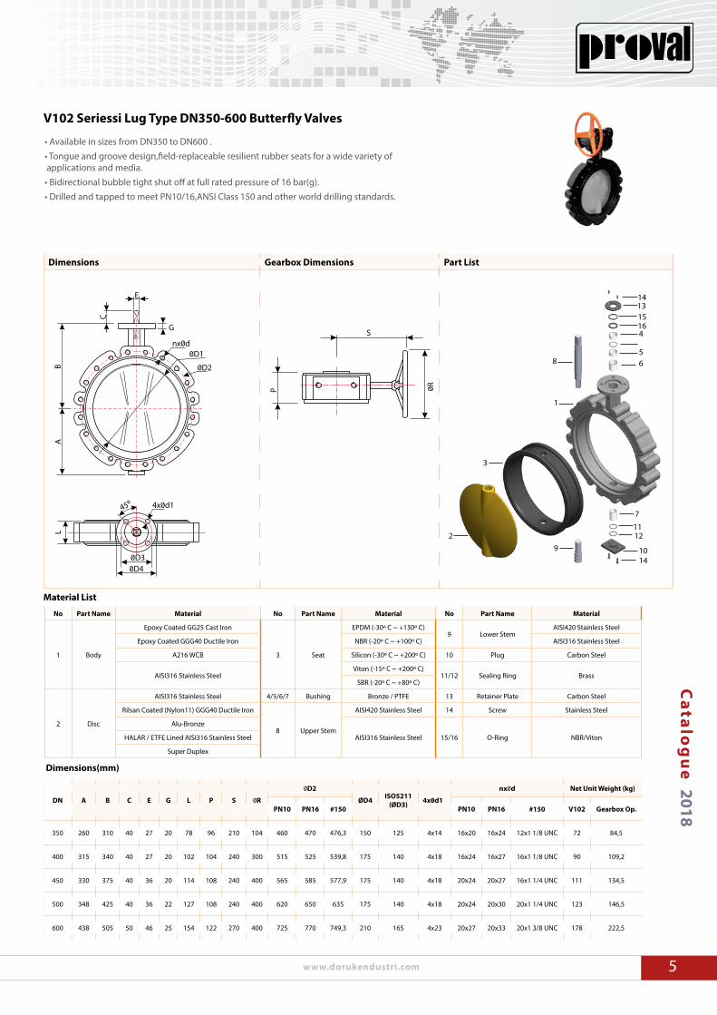
• Available in sizes from DN350 to DN600 .• Tongue and groove design,field-replaceable resilient rubber seats for a wide variety of applications and media.• Bidirectional bubble tight shut off at full rated pressure of 16 bar(g).• Drilled and tapped to meet PN10/16,ANSI Class 150 and other world drilling standards.
V102 Seriessi Lug Type DN350-600 Butterfly Valves
Material List
DN A B C E G L P S 0R
0D2
ØD4 ISO5211(ØD3) 4x0d1
nx0d Net Unit Weight (kg)
PN10 PN16 #150 PN10 PN16 #150 V102 Gearbox Op.
350 260 310 40 27 20 78 96 210 104 460 470 476,3 150 125 4x14 16x20 16x24 12x1 1/8 UNC 72 84,5
400 315 340 40 27 20 102 104 240 300 515 525 539,8 175 140 4x18 16x24 16x27 16x1 1/8 UNC 90 109,2
450 330 375 40 36 20 114 108 240 400 565 585 577,9 175 140 4x18 20x24 20x27 16x1 1/4 UNC 111 134,5
500 348 425 40 36 22 127 108 240 400 620 650 635 175 140 4x18 20x24 20x30 20x1 1/4 UNC 123 146,5
600 438 505 50 46 25 154 122 270 400 725 770 749,3 210 165 4x23 20x27 20x33 20x1 3/8 UNC 178 222,5
Dimensions(mm)
Dimensions Gearbox Dimensions Part List
S
0RP
nx0d
0D2
0D1
E
B
C
A
G
4x0d1
0D40D3
45º
6
7
1516
14
14
13
1211
109
85
4
3
2
1
L
No Part Name Material No Part Name Material No Part Name Material
1 Body
Epoxy Coated GG25 Cast Iron
3 Seat
EPDM (-30º C ~ +130º C)9 Lower Stem
AISI420 Stainless Steel
Epoxy Coated GGG40 Ductile Iron NBR (-20º C ~ +100º C) AISI316 Stainless Steel
A216 WCB Silicon (-30º C ~ +200º C) 10 Plug Carbon Steel
AISI316 Stainless SteelViton (-15º C ~ +200º C)
11/12 Sealing Ring BrassSBR (-20º C ~ +80º C)
2 Disc
AISI316 Stainless Steel 4/5/6/7 Bushing Bronze / PTFE 13 Retainer Plate Carbon Steel
Rilsan Coated (Nylon11) GGG40 Ductile Iron
8 Upper Stem
AISI420 Stainless Steel 14 Screw Stainless Steel
Alu-Bronze
AISI316 Stainless Steel 15/16 O-Ring NBR/VitonHALAR / ETFE Lined AISI316 Stainless Steel
Super Duplex

6 www.proval.net
Ca
talo
gu
e 2018
Pneumatically-Actuated Butterfly
Valve with Silicon Seat
Lug Type Butterfly Valves Flange Bolting Dimensions (mm)
V101/V102 Series Butterfly Valves Torque Values (Nm)
DNTorque (Nm)
PN10 PN16
50 10 12
65 12 15
80 26 40
100 24 44
125 80 85
150 60 90
200 130 140
250 300 350
300 310 350
DNTorque (Nm)
PN10 PN16
350 550 625
400 755 846
450 1012 1131
500 1350 1431
600 2111 2301
700 3272 3599
800 4308 4739
900 5257 5783
1000 8920 9819
1200 12555 13811
Size (DN) B
PN10 PN16 ANSI150
b L L1 d n b L L1 d n b L L1 d n
25 28 16 100 80 M12 4 16 100 80 M12 4 15 110 90 1/2” 13 UNC 4
32 33 16 110 90 M16 4 16 110 90 M16 4 16 110 90 1/2” 13 UNC 4
40 33 16 130 90 M16 4 16 130 90 M16 4 18 120 100 1/2” 13 UNC 4
50 43 18 130 110 M16 4 18 130 110 M16 4 19 140 110 5/8” 11 UNC 4
65 46 18 140 110 M16 4 18 140 110 M16 4 22 140 120 5/8” 11 UNC 4
80 52 20 150 120 M16 8 20 140 120 M16 8 24 160 130 5/8” 11 UNC 4
100 56 20 150 120 M16 8 20 150 120 M16 8 24 160 130 5/8” 11 UNC 8
125 56 22 160 130 M16 8 22 160 130 M16 8 25 170 140 3/4” 10 UNC 8
150 56 22 160 130 M20 8 22 160 130 M20 8 25 170 140 3/4” 10 UNC 8
200 60 24 170 140 M20 8 24 170 140 M20 12 29 190 160 3/4” 10 UNC 8
250 68 26 180 154 M20 12 26 190 160 M24 12 30 200 170 7/8” 9 UNC 12
300 78 26 200 170 M20 12 28 210 180 M24 12 32 220 190 7/8” 9 UNC 12
350 78 26 200 170 M20 16 30 210 180 M24 16 35 240 200 1” 8 UNC 12
400 102 26 230 200 M24 16 32 250 210 M24 16 37 240 220 1” 8 UNC 16
450 114 28 250 210 M24 20 34 260 230 M27 20 40 290 250 1 1/8” 7 UNC 16
500 127 28 260 230 M24 20 34 280 240 M30 20 43 310 270 1 1/8” 7 UNC 20
600 154 28 300 260 M27 20 36 320 280 M33 20 48 360 310 1 1/4” 7 UNC 20
Size(DN) BPN10 PN16 ANSI150
b L2 d n b L2 d n b L2 d n
50 43 18 40 M16 4 18 40 M16 4 19 45 5/8” 11 UNC 4
65 46 18 40 M16 4 18 40 M16 4 22 45 5/8” 11 UNC 4
80 52 20 40 M16 8 20 40 M16 8 24 45 5/8” 11 UNC 4
100 56 20 45 M16 8 20 45 M16 8 24 50 5/8” 11 UNC 8
125 56 22 50 M16 8 22 50 M16 8 25 50 3/4” 10 UNC 8
150 56 22 50 M20 8 22 50 M20 8 25 50 3/4” 10 UNC 8
200 60 24 55 M20 8 24 55 M20 12 29 60 3/4” 10 UNC 8
250 68 26 60 M20 12 26 60 M24 12 30 65 7/8” 9 UNC 12
300 78 26 60 M20 12 28 65 M24 12 32 70 7/8” 9 UNC 12
350 78 26 60 M20 16 30 65 M24 16 35 70 1” 8 UNC 12
400 102 26 65 M24 16 32 70 M24 16 37 75 1” 8 UNC 16
450 114 28 65 M24 20 34 70 M27 20 40 80 1 1/8” 7 UNC 16
500 127 28 65 M24 20 34 70 M30 20 43 80 1 1/8” 7 UNC 20
600 154 28 70 M27 20 36 75 M33 20 48 80 1 1/4” 7 UNC 20
Wafer Type Butterfly Valves Flange Bolting Dimensions (mm)
Installation using cap screws
BbL2
0dxn
Installation using a stud bolt ,two hexa-gon nuts and washers
BL
b 0dxn
Installation using Cap screws and nuts
B
L1
b 0dxn


![CATÁLOGO INTEVA (IN-2.1) [Modo de compatibilidad] · •Materials Body: AISI 303 / AISI316 / BRASS DIN-EN-12164 Seals:NBR,VitonorEPDM Back–Up-Ring:PTFE Balls: AISI 316W 14401 Springs:](https://img.pdfslide.us/doc/110x75/5b1a9d3a7f8b9a23258dc65d/catalogo-inteva-in-21-modo-de-compatibilidad-materials-body-aisi-303.jpg)