Embed Size (px)
Citation preview

Power Quality Guidebook - Page 1-
V
ol
ta
ge
Sag Solutions for
Industrial Customers
A guidebook by Tenaga Nasional Berhad
Voltage Sag Solutions for
Industrial Customers
5th edition
A Guidebook by Tenaga Nasional Berhad

Power Quality Guidebook - Page 2-
The suggestions contained in this book are generic in nature. The reader
must always consult the equipment manufacturer before applying any
suggestions. TNB and the editorial members shall not be held responsible
for any consequences arising from application of any suggestion contained
herein.
© Copyright 2018 Tenaga Nasional Berhad

Power Quality Guidebook - Page 3-
Prepared and Edited by:
Author
Ir.Dr.Mohamed Fuad Faisal Technical Specialist (Power Quality & EE)
Asset Management Strategy & Design Standard,
Distribution Network, Distribution Division TNB
Sirim Tech Committee on Power Quality
Sirim Tech Committee on Energy Efficiency
Sirim Tech Committee on Power Systems
Sirim Tech Committee on Electrical Installations &
Wiring
IEEE Power Energy Society
IEC TC77/SC77A/WG2 (Voltage fluctuations etc.)
IEC TC77/SC77A/WG8 (EMC Environment)
Editors
Wan Nazmy Wan Mahmood Senior General Manager (Distribution Network)
Distribution Division TNB
Rumaizi Abd Hamid General Manager (Asset Management Strategy &
Design Standard), Distribution Network
Distribution Division TNB
Prof. Dr.Azah Mohamed University Kebangsaan Malaysia (UKM)
Yap Kuan How Senior Engineer (Power Quality & EE)
Asset Management Strategy & Design Standard,
Distribution Network, Distribution Division TNB
Power Quality Guidebook - Page 4-
Foreword by President/CEO of TNB
First of all, congratulation to the Distribution Network,
Distribution Division TNB, for taking the initiative to
revise and continuously update the existing guidebook
book on ―Voltage Sag Solutions for Industrial
Customers‖.
The first edition of this guidebook was launched in 2007
with the objective to provide information to our
customers on voltage sag mitigations. This guidebook has
been updated due to introduction of new power quality
regulation requirement, revised technical standards, and
introduction of new technology for mitigating voltage
sags.
The guidebook defines the most important concept of electromagnetic environment for
the electrical power systems. Voltage sag is part of the electromagnetic environment for
power systems.
Nowadays, in the modern industrial facility, many electrical and electronic devices have
been incorporated with automated processes. No doubt that programmable logic
controller (PLCs), adjustable-speed drives (ASDs), energy efficient motors, computer
numerical control (CNC) machines, and other power electronic devices increase
productivity, increase the quality of products, and decrease the cost to customers of those
products. However, they also increase the equipment vulnerability to voltage sags. Due to
this, the critical equipment experienced unexplained process interruptions and unplanned
equipment shutdowns due to electromagnetic disturbances in particular due to voltage
sags.
I believe this 5th
edition power quality guidebook will provide more information on
electromagnetic compatibility (EMC) and measures to achieve EMC with the
electromagnetic environment. Both the IEC & IEEE standards clearly define the
definition of EMC and the responsibilities to achieve EMC for both power utility and
customers.
We at TNB are always willing to provide information and support our customers in their
efforts to improve the electromagnetic compatibility (EMC) of their installations.
Dato’ Azman Mohd
President/CEO
Tenaga Nasional Berhad

Power Quality Guidebook - Page 5-
Foreword by Chief Distribution Network Officer
Power Quality (PQ), which could be generally understood
by many as the variations in the supply voltage, is indeed
another critical dimension of service quality that TNB,
customers and other industry stakeholders need to
appreciate and contribute to manage under current and
future business scenarios.
The most significant category of PQ disturbance from the
perspective of both customers and power utility is the short
duration voltage disturbances or more commonly known
as voltage sags.
Voltage sags have been an intrinsic feature of public electricity supply since the earliest
times. Yet in recent decades they have become an increasingly troublesome disturbance,
giving rise to inconvenience and even considerable economic loss. The reason is that
some modern electricity utilisation equipment, either in its own design or because of
control features incorporated in it, has become more sensitive to voltage sags. There is
therefore a need for an increased awareness of the phenomenon among the suppliers and
users of electricity and the manufacturers of equipment.
This PQ guidebook is intended to provide useful illustrations to customers and utility
engineers on many possible solutions towards ensuring adequate equipment immunity
against voltage sags. Improving the immunity of highly sensitive equipment or controls
will go a long way in ensuring EMC of customer‘s equipment and processes to the power
system electromagnetic environment. Such investments on mitigating solutions can
indeed minimize costly equipment mal-operations and disruptions to manufacturing and
business processes.
Datuk Ir. Baharin Din
Chief Distribution Network Officer
Tenaga Nasional Berhad

Power Quality Guidebook - Page 6-
Chapters Page Number
Chapter 1 Introduction 9-21
1.1 Power Quality Definitions
1.2 Categories of Power Quality Disturbances
1.3 Brief Descriptions of all Power Quality Disturbances
1.4 Financial loss related to Power Quality Disturbances
Chapter 2 Steady State Supply Voltage Performance 22-25
Chapter 3 Understanding Electromagnetic Compatibility (EMC) 26-40
3.1 Introduction
3.2 Understanding Electromagnetic Disturbances
3.3 Understanding Power Quality and EMC
3.4 Common Power System Electromagnetic Phenomena
3.5 Definition of compatibility levels in industrial plants
3.6 Common Electromagnetic Environments
3.6.1 Electromagnetic environment defined by EN 50160
3.6.2 Electromagnetic environment defined by IEC 61000-2-4
3.7 Electromagnetic environment classes
3.8 Overcoming Electromagnetic Compatibility (EMC)
Chapter 4 Understanding Voltage Sags 41-73
4.1 Definition of voltage sags
4.1.1 Understanding the voltage sag information in TNB PQ SMS
4.2 Difference between voltage sag and voltage dip
4.3 Sources of voltage sags (dips)
4.4 Classification of voltage sags
4.5 Propagation of voltage sags.
4.6 Impact of voltage sags to industrial equipment
4.6.1 Impact of voltage sags to electronic equipment
4.6.2 Sensitive equipment in industrial plants
4.6.3 Impact of voltage sags to motors
4.6.4 Impact of voltage sags to lighting systems
4.7 Understanding level of equipment sensitivity to voltage sags
4.7.1 Understanding control level sensitivity to voltage sag
4.7.1.1 Understanding UnderVoltage Relay (UVR)
4.7.1.2 Understanding contactors
4.7.1.3 Understanding other sensitive electronic control system/equipment
4.7.1.4 Equipment fails because an unbalance relay trip.
4.7.1.5 A quick-acting relay shuts the system down
4.7.1.6 A reset circuit may incorrectly trip at the end of the voltage sag.
4.7.1.7 Understanding current transducer
Power Quality Guidebook - Page 7-
4.7.1.8 Understanding interlock sensitivity to voltage sags
4.8 Example of diagrams for control circuits for 3-phase equipment
Chapter 5 Monitoring Voltage Sags 74-88
5.1 Introduction
5.2 Power Quality Monitoring
5.2.1 Understanding True RMS meter
5.2.2 Description of PQ recording equipment
5.3 What to Monitor?
5.4 Locations to monitor Power Quality
5.5 Importance of having a good software to diagnose Power Quality
5.6 Examples on recorded waveforms for voltage sags
Chapter 6 Equipment Compatibility Requirement 89-97
6.1 Power quality design philosophy
6.2 Understanding equipment immunity requirement
6.3 Voltage sag immunity requirement
6.3.1 Available compatibility levels for voltage sags
6.3.2 Voltage tolerance curves
6.3.2.1 CBEMA standard
6.3.2.2 ITIC standard
6.3.2.3 SEMI F47 standard
6.3.2.4 IEC 61000-4-11 standard
6.3.2.5 IEC 61000-4-34 standard
Chapter 7 Characterizing Equipment Sensitivity 98-111
7.1 Introduction
7.2 Objective of equipment immunity testing
7.3 Analyzing machinery immunity and sensitivity to voltage sag
7.3.1 Simple method to verify the equipment sensitivity to voltage sags
7.3.2 Testing method to verify the equipment sensitivity to voltage sags
7.4 Evaluation of test results
7.5 Improving equipment immunity to voltage sag
7.6 Evaluating the Economics
7.7 Improving Equipment Ride-through Characteristics
Chapter 8 Solutions to Voltage Sags 112-133
8.1 Introduction
8.2 Equipment procurement specifications
8.3 Voltage sag solutions for existing industrial plant
8.3.1 Hardening requirement for control and logic circuits
8.3.1.1 SEMI F47 compliant power source

Power Quality Guidebook - Page 8-
8.3.1.2 Change the trip setting of protection relay (UVR etc.)
8.3.1.3 Installing a coil hold-in device
8.3.1.4 Implement auto restart schemes
8.3.1.5 To maintain the DC link voltage for ASD.
8.3.1.6 Change the settings for unbalance relay
8.3.1.7 Employ a time delay settings for reverse power relay
8.3.1.8 Overall actions for hardening the control circuit & protection relays
8.4 Single phase power conditioners for voltage sag mitigation
8.4.1 Sizing procedure for single-phase power conditioners
8.4.1.1 Uninterruptible Power Supply (UPS)
8.4.1.2 Constant Voltage Transformer (CVT)
8.4.1.3 Dip Proofing Inverter
8.4.1.4 Voltage Dip Compensator (VDC)
8.4.1.5 Dynamic Compensator (Dynacom)
8.4.1.6 Dynamic Sag Corrector (DySC)
Chapter 9 Large Scale Solutions to Voltage Sags 134-148
9.1 Introduction
9.1.1 Sizing procedure for three phase power conditioners
9.2 Three Phase Uninterruptible Power Supplies (UPS)
9.3 Active Voltage Conditioner (AVC)
9.4 Datawave
9.5 Flywheel
9.6 Dynamic Voltage Restorer (DVR)
9.7 Three phase Dynamic Compensator (Dynacom)
9.8 Dynamic Sag Corrector (ProDysc)
9.9 Dynamic Sag Corrector (MegaDysc)
9.10 UPS-I, Industrial UPS
9.11 Medium Voltage UPS
9.12 PureWave® Outdoor UPS Systems
9.13 Sag Fighter
10.0 Summary of Guidebook 149
References 151

Power Quality Guidebook - Page 9-
CHAPTER 1
OVERVIEW ON POWER QUALITY
1.0 INTRODUCTION
As factory automation continues to evolve with the movement of data centers
from computer rooms to the factory floor, the importance of power quality (PQ) has
escalated. The inclusion of more sensitive electronic equipment in industrial processes
demands the delivery of clean and stable power. Even the smallest service or process
interruption can have a devastating effect on the efficiency and productivity of a
company. The most obvious signs of a PQ problem include flickering lights, damaged
equipment or a complete loss of power. Shorter than expected life span of equipment or
unexplained shutdowns can also be a result of PQ problems. In some cases, such
problems are caused by improper wiring and grounding practices. PQ problems may also
be caused by natural disruptions such as lightning strikes, operations of large nonlinear
loads such as arc furnaces and large rotating motor loads. The types of PQ problems
frequently experienced by customers are voltage sags and harmonics while the less
frequent ones include transient, flicker and noise.
1.1 Power Quality Definitions
As any other product, electric power can also be characterized by the term quality.
Customer generally grades the quality of the electrical power based on the effects of
problems associated with the electric power supply. The more equipment outages, erratic
behaviour or damage, the worse is the understanding on power quality (PQ).
The Institution of Electrical, Electronic Engineers (IEEE) defines PQ as ―the
concept of powering and grounding sensitive electronic equipment in a manner that is
suitable to the operation of that equipment‖ [1]. Another definition of PQ is from IEC
61000-2-1. PQ is defined as conducted electromagnetic disturbances present in electrical
supply network in the frequency range from 0 to 9 kHz, with an extension up to 148.5

Power Quality Guidebook - Page 10-
kHz [2]. In power qualitu, the concept of Electromagnetic Compatibility (EMC) is
important to ensure minimum equipment mal-operation due to electromagnetic
environment. Electromagnetic Compatibility (EMC) is the ability of equipment or
systems to function satisfactorily in their electromagnetic environment without
introducing intolerable electromagnetic disturbances to anything in that environment.
While power quality is a convenient term for many, it is the quality of the voltage
- rather than power or electric current - that is actually described by the term. Power is
simply the flow of energy and the current demanded by a load is largely uncontrollable.
The quality of electrical power may be described as a set of values of parameters, such
as:-
Continuity of service
Variation in voltage magnitude
Transient voltages and currents
Harmonic content in the waveforms for AC power
It is often useful to think of power quality as a compatibility problem: is the
equipment connected to the grid compatible with the events on the grid, and is the power
delivered by the grid, including the events, compatible with the equipment that is
connected? Compatibility problems always have at least two solutions: in this case, either
clean up the power, or make the equipment tougher.
1.2 Categories of Power Quality Disturbances
Power quality or electromagnetic disturbance is defined as any electromagnetic
phenomenon which, by being present in the electromagnetic environment can cause
electrical equipment to depart from its intended performance. Electromagnetic
phenomena are low-frequency conducted disturbances in the frequency range from 0 kHz
to 9 kHz voltage deviations. An electromagnetic disturbance may be an electromagnetic
noise, an unwanted signal or an immediate change in the propagation medium. Table 1.1

Power Quality Guidebook - Page 11-
describes the IEEE categorization of electromagnetic disturbances used by the power
quality community [3].
Table 1.1 Classifications of Power Quality Disturbances (IEEE Std.1159 2009)
Category of disturbance Typical
spectral
content
Typical
duration
Typical voltage
magnitude in
per unit (pu)
Impulsive transients
Nanosecond
Microsecond
Millisecond
Oscillatory transients
Low frequency
Medium frequency
High frequency
5 nsec rise
1µsec rise
0.1 msec rise
< 5 kHz
5 – 500 kHz
0.5 – 5 MHz
< 50 nsec
50 nsec – 1msec
> 1 msec
0.3 – 50 msec
20 µsec
5 µsec
0 – 4pu
0 – 4pu
0 – 4pu
Short duration variations
Instantaneous
Interruption
Sag
Swell
Momentary
Interruption
Sag
Swell
Temporary
Interruption
Sag
Swell
0.5 – 30 cycles
0.5 – 30 cycles
0.5 – 30 cycles
30 cycles – 3 sec
30 cycles – 3 sec
30 cycles – 3 sec
3 sec – 1 min
3 sec – 1 min
3 sec – 1 min
< 0.1pu
0.1 – 0.9pu
1.1 – 1.8pu
< 0.1pu
0.1 – 0.9pu
1.1 – 1.4pu
< 0.1pu
0.1 – 0.9pu
1.1 – 1.2pu
Long duration variations
Interruption sustained
Undervoltage
Overvoltage
> 1 min
> 1 min
> 1 min
< 0.1pu
0.9 – 0.1pu
>1.1pu
continue …
Power Quality Guidebook - Page 12-
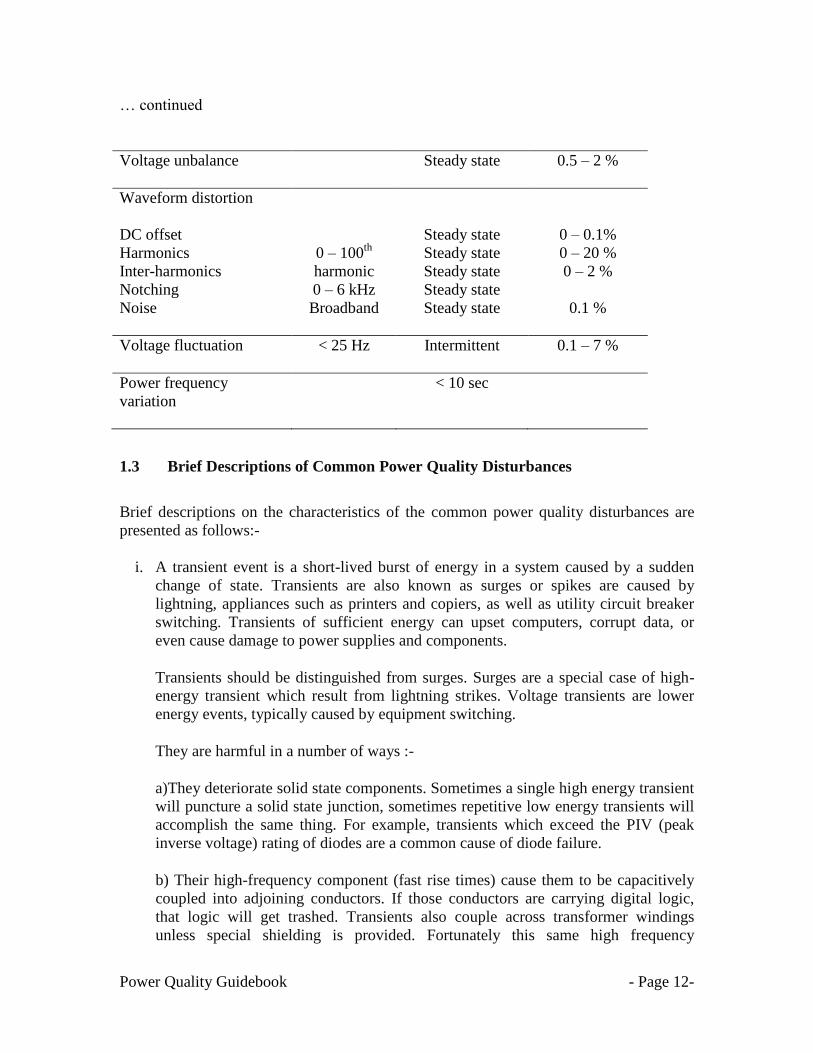
… continued
Voltage unbalance
Steady state 0.5 – 2 %
Waveform distortion
DC offset
Harmonics
Inter-harmonics
Notching
Noise
0 – 100th
harmonic
0 – 6 kHz
Broadband
Steady state
Steady state
Steady state
Steady state
Steady state
0 – 0.1%
0 – 20 %
0 – 2 %
0.1 %
Voltage fluctuation
< 25 Hz
Intermittent 0.1 – 7 %
Power frequency
variation
< 10 sec
1.3 Brief Descriptions of Common Power Quality Disturbances
Brief descriptions on the characteristics of the common power quality disturbances are
presented as follows:-
i. A transient event is a short-lived burst of energy in a system caused by a sudden
change of state. Transients are also known as surges or spikes are caused by
lightning, appliances such as printers and copiers, as well as utility circuit breaker
switching. Transients of sufficient energy can upset computers, corrupt data, or
even cause damage to power supplies and components.
Transients should be distinguished from surges. Surges are a special case of high-
energy transient which result from lightning strikes. Voltage transients are lower
energy events, typically caused by equipment switching.
They are harmful in a number of ways :-
a)They deteriorate solid state components. Sometimes a single high energy transient
will puncture a solid state junction, sometimes repetitive low energy transients will
accomplish the same thing. For example, transients which exceed the PIV (peak
inverse voltage) rating of diodes are a common cause of diode failure.
b) Their high-frequency component (fast rise times) cause them to be capacitively
coupled into adjoining conductors. If those conductors are carrying digital logic,
that logic will get trashed. Transients also couple across transformer windings
unless special shielding is provided. Fortunately this same high frequency

Power Quality Guidebook - Page 13-
component causes transients to be relatively localized, since they are damped
(attenuated) by the impedance of the conductors (inductive reactance increases with
frequency).
Transients can be categorized by waveform. The first category is "impulsive"
transients, commonly called "spikes," because a high-frequency spike protrudes
from the waveform. The capacitor switching transient, on the other hand, is an
"oscillatory" transient because a ringing waveform rides on and distorts the normal
waveform. It is lower frequency, but higher energy.
Impulsive transients are sudden high peak events that raise the voltage and/or
current levels in either a positive or a negative direction. These types of events can
be categorized further by the speed at which they occur (fast, medium, and slow).
Impulsive transients can be very fast events (5 nanoseconds [ns] rise time from
steady state to the peak of the impulse) of short-term duration (less than 50 ns).
An oscillatory transient is a sudden change in the steady-state condition of a signal's
voltage, current, or both, at both the positive and negative signal limits, oscillating
at the natural system frequency. In simple terms, the transient causes the power
signal to alternately swell and then shrink, very rapidly. Oscillatory transients
usually decay to zero within a cycle (a decaying oscillation).
ii. Voltage step change: A single variation of the rms value or the peak value of the
supply voltage (unspecified with respect to form and duration).
iii. Voltage sag is a brief drop in voltage and is caused by motor starting, heaters in
printers and copiers cycling, as well as faults in the power system. Sags often cause
lights to dim or flicker, computer equipment to lock up or lose memory etc.
iv. Voltage swell is a brief increase in the normal voltage level. Most swells are caused
by stopping of a motor or single line to ground fault. Although not generally a
problem, swells have been known to cause failure of marginal components in
electronic equipment.
v. Harmonics are sinusoidal voltages or currents having frequencies that are whole
multiples of the frequency at which the supply system is designed to operate (e.g.
50Hz or 60 Hz).
Harmonics are a regular distortion of the voltage waveform often caused by the
power supplies of electronic equipment. Harmonics can cause overheating in
transformers, building wiring, and motors.
vi. DC offset: Direct current (DC) can be induced into an AC distribution system, often
due to failure of rectifiers within the many AC to DC conversion technologies that
have proliferated modern equipment. DC can traverse the ac power system and add
unwanted current to devices already operating at their rated level. Overheating and

Power Quality Guidebook - Page 14-
saturation of transformers can be the result of circulating DC currents. When a
transformer saturates, it not only gets hot, but also is unable to deliver full power to
the load, and the subsequent waveform distortion can create further instability in
electronic load equipment.
vii. Noise is unwanted voltage or current superimposed on the power system voltage or
current waveform. Noise can be generated by power electronic devices, control
circuits, arc welders, switching power supplies, radio transmitters and so on. Poorly
grounded sites make the system more susceptible to noise. Noise can cause
technical equipment problems such as data errors, equipment malfunction, long-
term component failure, hard disk failure, and distorted video displays.
Noise due to radio frequency interference is electrical interference from equipment
that radiates high frequency electrical energy such as TV/radio transmitters and cell
phones. Interference can also be caused by arcing sources or switching power
supplies such as those found in electronic ballasts and adjustable speed drives. This
kind of noise often causes interference to control circuits.
viii. Power-line flicker is a visible change in brightness of a lamp due to rapid
fluctuations in the voltage of the power supply. The source of this is the voltage
drop generated over the source impedance of the grid by the changing load current
of an equipment or facility. These fluctuations in time generate flicker. The effects
can range from disturbance to epileptic attacks of photosensitive persons. Flicker
may also affect sensitive electronic equipment such as television receivers or
industrial processes relying on constant electrical power.
Flicker may be produced, for example, if a steel mill uses large industrial electric
motors or arc furnaces on a distribution network, or frequent starting of an electric
motor, or if a rural residence has a large water pump starting regularly on a long
feeder system.
ix. Voltage notching is described as a recurring power quality disturbance due to the
normal operation of power electronic devices (i.e. rectifier), when current is
commutated from one phase to another
Voltage notching is primarily caused by three-phase rectifiers or converters that
generate continuous DC current. Voltage notches happen when the current
commutates from one phase to another. Subsequently, a momentary short circuit
between two phases will occur during this period.
In addition, voltage notching characterizes an unusual case that falls between
harmonics and transients. This is because notching takes place in steady-state, thus,
it can be distinguished by the harmonic spectrum of the affected voltage. On the
other hand, the components of the frequency related to voltage notching are
somewhat high and may not be promptly categorized with a measurement device
commonly employed for harmonic analysis.

Power Quality Guidebook - Page 15-
x. Voltage unbalance occurs when the RMS line voltages on a poly-phase system are
unequal. Voltages are seldom perfectly balanced between phases, but when this
unbalance becomes excessive, it can create problems for poly-phase motors. Many
of the newer induction motors are now more sensitive to unbalance than the older
designs, and furthermore, adjustable speed drives can be even more vulnerable than
standard motors.
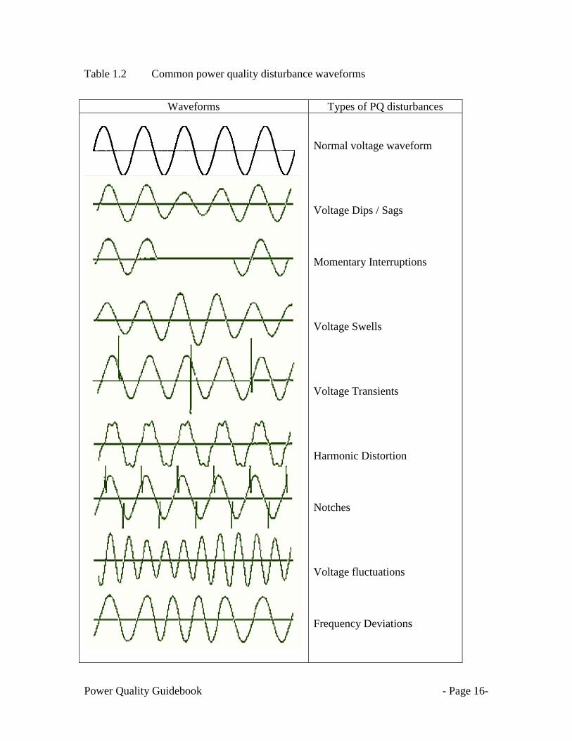
Table 1.2 shows the common voltage waveforms for the respective PQ disturbances.
Power Quality Guidebook - Page 16-
Table 1.2 Common power quality disturbance waveforms
Waveforms Types of PQ disturbances
Normal voltage waveform
Voltage Dips / Sags
Momentary Interruptions
Voltage Swells
Voltage Transients
Harmonic Distortion
Notches
Voltage fluctuations
Frequency Deviations

Power Quality Guidebook - Page 17-
1.4 Financial loss related to Power Quality Disturbances
Power quality issues can cause business problems for industrial customers such as:-
Lost productivity, idle people and equipment
Equipment damage or failure
Lost orders, good will, customers and profits
Lost transactions and orders not being processed
Revenue and accounting problems such as invoices not prepared, payments held
up, and early payment discounts missed
Customer and/or management dissatisfaction
Overtime required to make up for lost work time
1.4.1 Financial loss related to Voltage Sag Disturbances
It is almost impossible to define a specific cost that can be related to some kind of
standardized voltage sag, but there are some figures that can serve as guidelines to show
the financial losses and the importance of voltage sag immunity. In the semiconductor
industry, an interruption is very expensive. A manufacturer organisation, SEMI, has
developed guidelines, test procedure and limits for voltage dip susceptibility for different
types of equipment used in their factories [4]. SEMI also promotes minimum immunity
requirement against voltage sags for essential semiconductor equipment.
There were few surveys conducted to document the monetary losses due to power quality
in particular due to voltage sags. In November 2002, T. Andersson and D. Nilsson
documented the sensitivity and cost of losses based on selected types on industries with
regard to voltage sag [5]. An overview of different costs related to voltage sags in
different industries is shown in Figure 1.1.

Power Quality Guidebook - Page 18-
,
Figure 1.1 Estimated cost of losses due to voltage sags
Sensitivity of different industries to voltage sags expressed in estimated sags cost per
industry. The highest position in this ranking is occupied by semiconductor industry
which, experience the highest level of voltage sags cost compared to electricity bill or
company turnover of any sector.
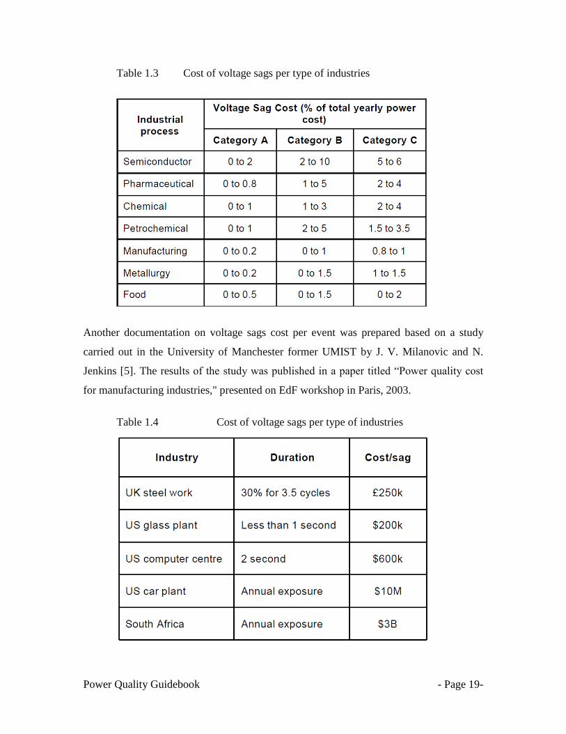
In another survey performed in 2003 by S. Quaia and F. Tosato [5], a survey on costs of
voltage sags were documented for a range of industrial sectors. The results of the survey
are shown in Table 1.3. The table presents the estimated voltage sag costs for a range of
industrial sectors.
Power Quality Guidebook - Page 19-
Table 1.3 Cost of voltage sags per type of industries
Another documentation on voltage sags cost per event was prepared based on a study
carried out in the University of Manchester former UMIST by J. V. Milanovic and N.
Jenkins [5]. The results of the study was published in a paper titled ―Power quality cost
for manufacturing industries," presented on EdF workshop in Paris, 2003.
Table 1.4 Cost of voltage sags per type of industries

Power Quality Guidebook - Page 20-
The latest power quality survey was conducted by Leonardo Energy [5]. The main
purpose of this project was to estimate the costs of wastage generated by inadequate
power quality for those sectors within the EU-25 for which electrical power is critical. PQ
costs reported in the categories of interruptions and voltage quality. All these cost were
specified on an annual basis. The survey interviews and web based submission were
conducted over a 2-year period in 8 European countries. In all, 62 complete and 6 partial
(i.e. excluding detailed cases part) interviews were carried out. The results of the survey
on reported number of PQ events in 12 months are shown in Table 1.5.
Table 1.5 Number of power quality events per industries
Type of
industries
Number of events Annual %
Voltage
sags
Short
Interruption
Long
interruptions
Surges &
transients Harmonics
Industry 15.7 6.9 2.2 13 9.0%
Services 7.7 5.4 2.1 6.7 7.5%
Average 13.2 6.4 2.2 11.3 8.5%
From the survey, the financial losses due to poor Power Quality amount to a total of €150
billion annually in the EU-25. The summary of this survey is as follows:-
Voltage sags, short interruptions, surges and transients account for 80-90% of the
€150bn financial costs/ wastage
Equipment damage and operational waste (unrecoverable work in progress &
Under performance) account for similar proportions of the totals identified
For the most sensitive industrial sectors representing €3.63 trillion (or 20% of
EU25 overall turnover) PQ costs amounts about 4% of their turnover.
The unit costs (per event) of PQ disturbances are:-
The cost per voltage dip event is between 2,000 and 4,000€.
Single short interruptions on average are 3.5 times more costly for industry and 9
times more costly for services.

Power Quality Guidebook - Page 21-
The average cost of long interruptions is 90,000€ and is more homogenous across
the whole survey sample.
Assessing the generic cost per event for surges and transients is more problematic
because of the lack of other research into these PQ phenomena. For this Survey it
spans between 120,000€ and 180,000€.
Figure 1.2 PQ cost to EU economy in LPQI surveyed sectors
On average the absolute share of impacts of the 6 categories of PQ disturbances taken
from the total survey sample is as follows:-
Voltage dips 23.6%
Short interruptions 18.8%
Long interruptions 12.5%
Harmonics 5.4%
Transients and surges 29%
Other 10.7%
The summary of this study identifies that the industry wasted a huge amount of resource
unnecessarily due to PQ disturbances.

Power Quality Guidebook - Page 22-
CHAPTER 2
STEADY STATE SUPPLY VOLTAGE PERFORMANCE
Before more details are presented on the definition of electromagnetic disturbances, it
is good that we first understand the definition of voltage regulation. The term "voltage
regulation" is used to discuss long term variations in voltage. It does not include short
term variations, which are generally called voltage sags, voltage swells and transients.
The ability of equipment to handle steady state voltage variations varies from equipment
to equipment. The steady state voltage variation limits for equipment is usually part of the
equipment specifications. The Information Technology Industry Council (ITIC) specifies
equipment withstand recommendations for IT equipment according to the ITI Curve
(formerly the CBEMA curve). The 1996 ITI Curve specifies that equipment should be
able to withstand voltage variations within +/- 10% of nominal voltage (variations that
last longer than 10 seconds) [6].
In Malaysia, the voltage regulation requirements are defined in two categories: -
Range A is for normal conditions and the required regulation is as follows:
Table 2.1 Normal steady state voltage regulations
Nominal Voltage
% Variation of nominal voltage
400V and 230V -6% and +10%
6.6kV, 11kV, 22kV, 33kV 5%
132kV and 275kV 5%
Range B is for short durations or unusual conditions.
Under contingency condition, when one or more circuit elements are on outage, the
power frequency steady-state voltage at all points in the utility‘s distribution system

Power Quality Guidebook - Page 23-
including the points before the consumer metering must be planned to be maintained
as follows:
Table 2.2 Steady state voltage regulation limits under contingency condition
Nominal Voltage
% Variation of nominal voltage
400V and 230V 10%
6.6kV, 11kV, 22kV, 33kV 10%
132kV and 275kV 10%
2.1 Common misunderstanding on settings for UnderVoltage Relay (UVR)
Most customers and consultants are often confused between the definition of
voltage regulation and voltage sags. Most consultants assumed the % ranges of the
voltage regulations are also the maximum and minimum voltages that all equipment will
be exposed to when connected to an electrical power system. The common mistake will
be on the application and settings of the UnderVoltage Relay (UVR) to initiate the
opening of circuit breaker (CB) and operation of standby generator during a power
outage. During the occurrence of a voltage sag event, the CB will also operate and cause
power interruption to the customers. In order for the UVR to operate properly, a time
delay scheme must be part of the UVR.
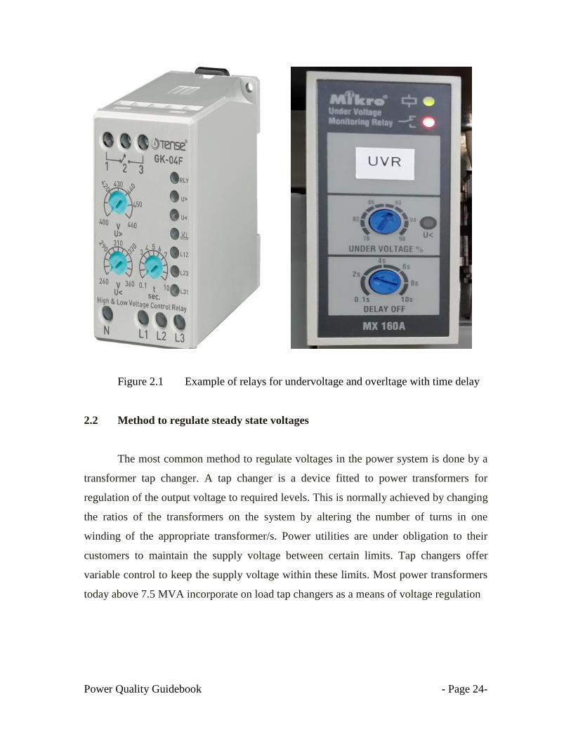
Examples of relays with time delay schemes are shown in Figure 2.1. Details on
the recommended settings (voltage magnitude and duration) for the UVR will be
presented in Chapter 8 in this guidebook.
Power Quality Guidebook - Page 24-
Figure 2.1 Example of relays for undervoltage and overltage with time delay
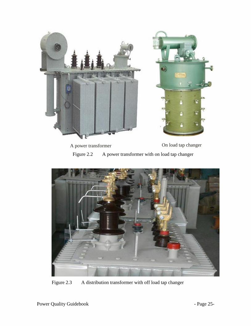
2.2 Method to regulate steady state voltages
The most common method to regulate voltages in the power system is done by a
transformer tap changer. A tap changer is a device fitted to power transformers for
regulation of the output voltage to required levels. This is normally achieved by changing
the ratios of the transformers on the system by altering the number of turns in one
winding of the appropriate transformer/s. Power utilities are under obligation to their
customers to maintain the supply voltage between certain limits. Tap changers offer
variable control to keep the supply voltage within these limits. Most power transformers
today above 7.5 MVA incorporate on load tap changers as a means of voltage regulation
Power Quality Guidebook - Page 25-
A power transformer
On load tap changer
Figure 2.2 A power transformer with on load tap changer
Figure 2.3 A distribution transformer with off load tap changer
Power Quality Guidebook - Page 26-
CHAPTER 3
UNDERSTANDING ELECTROMAGNETIC COMPATIBILITY (EMC)
3.1 Introduction
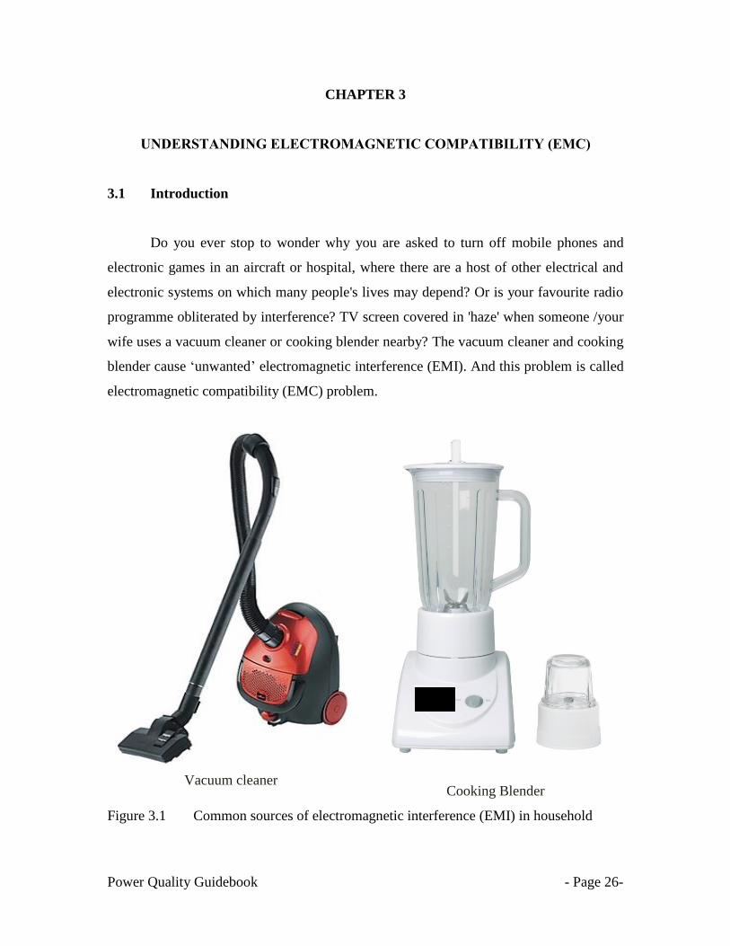
Do you ever stop to wonder why you are asked to turn off mobile phones and
electronic games in an aircraft or hospital, where there are a host of other electrical and
electronic systems on which many people's lives may depend? Or is your favourite radio
programme obliterated by interference? TV screen covered in 'haze' when someone /your
wife uses a vacuum cleaner or cooking blender nearby? The vacuum cleaner and cooking
blender cause ‗unwanted‘ electromagnetic interference (EMI). And this problem is called
electromagnetic compatibility (EMC) problem.
Vacuum cleaner
Cooking Blender
Figure 3.1 Common sources of electromagnetic interference (EMI) in household
Power Quality Guidebook - Page 27-
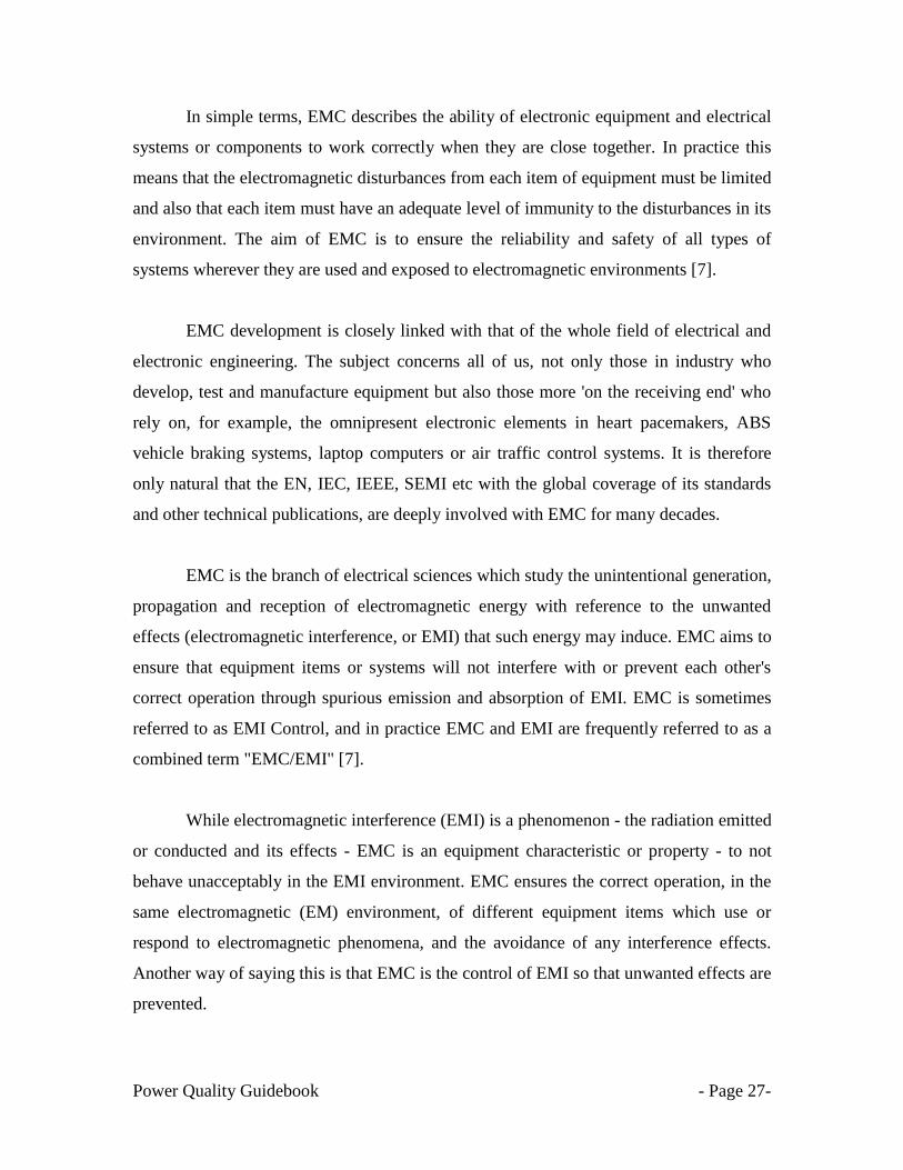
In simple terms, EMC describes the ability of electronic equipment and electrical
systems or components to work correctly when they are close together. In practice this
means that the electromagnetic disturbances from each item of equipment must be limited
and also that each item must have an adequate level of immunity to the disturbances in its
environment. The aim of EMC is to ensure the reliability and safety of all types of
systems wherever they are used and exposed to electromagnetic environments [7].
EMC development is closely linked with that of the whole field of electrical and
electronic engineering. The subject concerns all of us, not only those in industry who
develop, test and manufacture equipment but also those more 'on the receiving end' who
rely on, for example, the omnipresent electronic elements in heart pacemakers, ABS
vehicle braking systems, laptop computers or air traffic control systems. It is therefore
only natural that the EN, IEC, IEEE, SEMI etc with the global coverage of its standards
and other technical publications, are deeply involved with EMC for many decades.
EMC is the branch of electrical sciences which study the unintentional generation,
propagation and reception of electromagnetic energy with reference to the unwanted
effects (electromagnetic interference, or EMI) that such energy may induce. EMC aims to
ensure that equipment items or systems will not interfere with or prevent each other's
correct operation through spurious emission and absorption of EMI. EMC is sometimes
referred to as EMI Control, and in practice EMC and EMI are frequently referred to as a
combined term "EMC/EMI" [7].
While electromagnetic interference (EMI) is a phenomenon - the radiation emitted
or conducted and its effects - EMC is an equipment characteristic or property - to not
behave unacceptably in the EMI environment. EMC ensures the correct operation, in the
same electromagnetic (EM) environment, of different equipment items which use or
respond to electromagnetic phenomena, and the avoidance of any interference effects.
Another way of saying this is that EMC is the control of EMI so that unwanted effects are
prevented.
Power Quality Guidebook - Page 28-
An electromagnetic (EM) environment is created by the introduction of any
electromagnetic phenomena/disturbance to a network/location that has electrical or
electronic device in operation. Any electromagnetic phenomena/disturbance created by
an appliance other that those intended for its practical use are regarded as electromagnetic
interference (EMI). EMI spreads from one appliance to another via cables or as radiation.
Phenomena such as stripes on a TV screen, the crackling of a radio or malfunctioning of a
computer are often manifestations of interference caused by other electrical appliances.
The term EMI better reflects the fact that electrical and electronic systems may
cause disturbances at any frequency between 0 Hz and the GHz (microwave) range. For
the purposes of its EMC-related publications, IEC defines the EM environment as "the
totality of EM phenomena existing at a given location."
EMC can be divided into a number of issues:
EMI is the radiation emitted and its effects on the victim.
Emission is the unwanted generation of electromagnetic energy by some emitter
or source.
Susceptibility or Immunity is the ability of the receptor or victim equipment to
operate correctly in the presence of electromagnetic disturbances. Susceptibility
and immunity are opposites - an equipment which has high susceptibility has low
immunity, and vice versa.
Coupling is the mechanisms by which EMI is able to travel from source to victim.
Besides understanding the phenomena in themselves, EMC also addresses the
countermeasures, such as control regimes, design and measurement, which should be
taken in order to prevent emissions from causing any adverse effect
Power Quality Guidebook - Page 29-
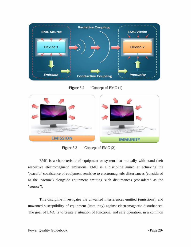
Figure 3.2 Concept of EMC (1)
Figure 3.3 Concept of EMC (2)
EMC is a characteristic of equipment or system that mutually with stand their
respective electromagnetic emissions. EMC is a discipline aimed at achieving the
'peaceful' coexistence of equipment sensitive to electromagnetic disturbances (considered
as the "victim") alongside equipment emitting such disturbances (considered as the
"source").
This discipline investigates the unwanted interferences emitted (emissions), and
unwanted susceptibility of equipment (immunity) against electromagnetic disturbances.
The goal of EMC is to create a situation of functional and safe operation, in a common
Power Quality Guidebook - Page 30-
electromagnetic environment, of different equipment and the avoidance of any
interference effects.
As well as safety, reliability and serviceability, electrical appliances must meet the
further requirement of interference-free operation in the presence of other equipment in
their intended operating environments. Interference-free operation of appliances intended
for use in the same operating environment is guaranteed by electromagnetic compatibility
(EMC). An electrical appliance must not generate unreasonable interference in its
environment and must also tolerate reasonable levels of outside interference.
3.2 Understanding Electromagnetic Disturbances
Electromagnetic disturbance is an electromagnetic event, which may degrade the
performance of a device, equipment or system, or adversely affect living or inert matter.
An electromagnetic disturbance may be an electromagnetic noise, an unwanted signal or
an immediate change in the propagation medium.
3.3 Understanding Power Quality and EMC
The IEC 61000 Electromagnetic Compatibility (EMC) standard is the counterpart
of the IEEE power quality standards. It is important to note that IEC does not yet use the
term power quality in any of its standard documents. Instead the IEC uses the term
electromagnetic compatibility, which is not the same as PQ but there is a strong overlap
between the two terms.
According to IEC 61000-2-1, PQ is defined as conducted electromagnetic
disturbances present in electrical supply network in the frequency range from 0 to 9 kHz,
with an extension up to 148.5 kHz. An electromagnetic disturbance is any
electromagnetic phenomenon which, by being present in the electromagnetic
environment that can cause electrical equipment to depart from its intended performance
[2].
Power Quality Guidebook - Page 31-
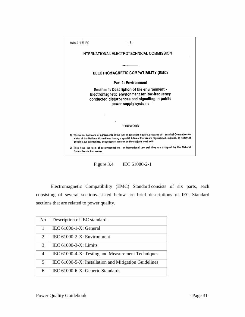
Figure 3.4 IEC 61000-2-1
Electromagnetic Compatibility (EMC) Standard consists of six parts, each
consisting of several sections. Listed below are brief descriptions of IEC Standard
sections that are related to power quality.
No Description of IEC standard
1 IEC 61000-1-X: General
2 IEC 61000-2-X: Environment
3 IEC 61000-3-X: Limits
4 IEC 61000-4-X: Testing and Measurement Techniques
5 IEC 61000-5-X: Installation and Mitigation Guidelines
6 IEC 61000-6-X: Generic Standards
Power Quality Guidebook - Page 32-
The issue of power quality is termed as an electromagnetic compatibility (EMC)
problem between the electricity supply and the customers‘ equipment. Electromagnetic
compatibility (EMC) itself is defined as: ―the ability of an equipment or system to
function satisfactorily in its electromagnetic (EM) environment (immunity) without
introducing intolerable electromagnetic disturbances to anything in that environment
(emission)‖.
The concept of electromagnetic compatibility (EMC) is important to ensure
minimum equipment mal-operation due to its electromagnetic environment.
Electromagnetic compatibility (EMC) is concerned with the possible degradation of the
performance of electrical and electronic equipment due to the disturbances present in the
electromagnetic environment in which the equipment operates. To ensure compatibility,
there are two essential requirements:
the emission of disturbances into the electromagnetic environment must be
maintained below a level that would not cause an unacceptable degradation of the
performance of equipment operating in that environment.
all equipment operating in the electromagnetic environment must have sufficient
immunity from all disturbances at the levels at which they exist in the environment.
Limits for emission and immunity cannot be set independently of each other. Clearly, the
more effectively emissions are controlled, the less restrictive are the immunity demands
that have to be placed on equipment. Similarly, if equipment is highly immune, there is
less need for stringent limits on the emission of disturbances.
A range of technical standards/guidelines had been published to address the fundamental
electromagnetic compatibility (EMC) issues governing the connection of sensitive
equipment to a electrical power system. Standards documentation sets out guidelines for
equipment connectivity and regulation of both conducted and radiated EMC emission and

Power Quality Guidebook - Page 33-
susceptibility. A sub-set of most EMC standards documentation governs the susceptibility
of sensitive equipment to voltage sags and surges.
3.4 Common Power System Electromagnetic Phenomena
The IEEE 1159:2009 contains several additional terms related to the IEC terminology.
The term voltage sag is used synonymously with the IEC term, voltage dip. The category
of short duration variation is used to refer to the voltage dips and short interruptions as
defined by the IEC standards [3].
The category of waveform distortion is used as a container category for the IEC
harmonics, inter harmonics and dc in ac networks phenomena as well as an additional
events from IEEE 519 called notching. Table 1.1 describes the IEEE categorization of
electromagnetic phenomena used by the power quality community.
3.5 Definition of compatibility levels in industrial plants
A compatibility level is a specified electromagnetic disturbance level used as a
reference level in a specified environment for coordination in the setting of emission and
immunity limits. The compatibility levels are set down for the various disturbances on an
individual basis only. However, the electromagnetic environment usually contains several
disturbances simultaneously, and the performance of some equipment can be degraded by
particular combinations of disturbances.

Power Quality Guidebook - Page 34-
Figure 3.4 Definition of compatibility level
The goal of EMC is the correct operation of different equipment in the same
electromagnetic environment, which involves electromagnetic phenomena in their
operation. In order to achieve such objective, EMC pursues two different issues, namely
emission and immunity compatibility levels. Emission issue is related to the reduction of
unintentional generation of electromagnetic energy to avoid the propagation of such
energy towards the external environment while immunity issue refers to the correct
operation of electrical equipment in the presence of electromagnetic disturbances.
There are two aspects to EMC:-
firstly, a piece of equipment should be able to operate normally in its environment
secondly, it should not pollute the environment too much.
An agreement on immunity level is a matter of foremost concern between
equipment manufacturers, utilities and customers. It is important that all sensitive

Power Quality Guidebook - Page 35-
equipment should be immune to its electromagnetic environment. A device connected to
the electrical power system can be exposed to an electromagnetic environment not only
due to the combined emission of all other devices connected to the system but also due to
all kinds of events in the power system like switching actions, short circuit faults and
lightning strikes. The immunity of a device should be assessed with reference to the
compatibility level of the electromagnetic environment, for example, the frequency of
voltage sags to be expected at a location concerned.
In-plant point of common coupling (IPCs) should be categorized according to
their compatibility levels. To enable the selection of specific equipment or devices such
as electronic machine, rotating machines, power-capacitor banks, filters etc. it may be
necessary to obtain a specific description of the electromagnetic environment (voltage
deviations) that may be present at the equipment terminals. Examples of common
electromagnetic environment or voltage characteristics to be expected in public power
systems are documented in BS EN 50160 (2000) and IEC 61000-2-4 (2006:13) as shown
in Tables 3.1 and 3.2, respectively. The ranges of the acceptable limits are the numbers of
electromagnetic disturbances in the electrical power systems to be experienced in 12
months.

Power Quality Guidebook - Page 36-
3.6 Common Electromagnetic Environments
3.6.1 Electromagnetic environment defined by EN 50160 [8].
Figure 3.5 The EN 50160 standard
Table 3.1 EN 50160 2000: Voltage characteristics for public power systems
Supply voltage
phenomenon
Acceptable limits Measurement
Interval
Grid frequency 49.5Hz to 50.5Hz
47Hz to 52Hz
10 s
Slow voltage changes 230Volt ± 10% 10 min
Voltage Sags or Dips
(≤1min)
10 to 1000 times
(under 85% of nominal)
10 ms
Short Interruptions
(≤ 3min)
10 to 100 times per year
(under 1% of nominal)
10 ms
Accidental, long
interruptions (> 3min)
10 to 50 times per year
(under 1% of nominal)
10 ms
Voltage unbalance Mostly 2% but occasionally 3% 10 min
Harmonic Voltages 8% Total Harmonic Distortion 10 min

Power Quality Guidebook - Page 37-
3.6.2 Electromagnetic environment defined by IEC 61000-2-4 [9].
Figure 3.6 The IEC 61000-2-4 standard
Table 3.2 IEC 61000-2-4: Voltage characteristics for public power system
Supply Voltage Phenomenon Acceptable limits Measurement
Interval
Grid frequency 49.5Hz to 50.5Hz 10 s
Slow voltage changes 230Volt ± 8% 10 min
Voltage Sags or Dips (≤1min) 100 times (Rural /
Overhead system)
10-100 times
(Urban/Underground system)
10 ms
Short Interruptions (≤ 3min) 10 to 100 times per year
(under 1% of nominal)
10 ms
Transient over-voltages
(line-to-ground)
Mostly < 6kV N/A
Voltage unbalance 2% 10 min
Harmonic Voltages 8% Total Harmonic Distortion 10 min

Power Quality Guidebook - Page 38-
3.7 Electromagnetic environment classes
The following classes of electromagnetic environment have been summarized from the
IEC 61000-2-4 [9].
Class 1
This class applies to protected supplies and has compatibility levels lower than public
network levels. It relates to the use of equipment very sensitive to disturbances in the
power supply, for instance the instrumentation of technological laboratories, some
automation and protection equipment, some computers, etc.
NOTE Class 1 environments normally contain equipment which requires protection by
such apparatus as uninterruptible power supplies (UPS), filters, or surge suppressers.
Class 2
This class applies to points of common coupling (PCC‘s for consumer systems) and in-
plant points of common coupling (IPC‘s) in the industrial environment in general. The
compatibility levels in this class are identical to those of public networks; therefore
components designed for application in public networks may be used in this class of
industrial environment.
Class 3
This class applies only to IPC‘s in industrial environments. It has higher compatibility
levels than those of class 2 for some disturbance phenomena. For instance, this class
should be considered when any of the following conditions are met:-
– a major part of the load is fed through converters;
– welding machines are present;
– large motors are frequently started;
– voltage sensitive loads
– loads vary rapidly

Power Quality Guidebook - Page 39-
NOTE 1: The supply to highly disturbing loads, such as arc-furnaces and large converters
which are generally supplied from a segregated bus-bar, frequently has disturbance levels
in excess of class 3 (harsh environment). In such special situations, the compatibility
levels should be agreed upon.
NOTE 2: The class applicable for new plants and extensions of existing plants should
relate to the type of equipment and process under consideration.
Class 4
This class applies to points of common coupling (PCC‘s for consumer systems) and in-
plant points of common coupling (IPC‘s) ONLY for semiconductor industry. The
compatibility levels in this class are identical to those of Semiconductor industrial
standard SEMI F47-0706.; therefore components designed for application in
semiconductor industry may be used in this class of industrial environment.
3.8 Overcoming Electromagnetic Compatibility (EMC) Issues
EMC is a characteristic of equipment or systems that mutually withstand their
respective electromagnetic emissions. Equipment and systems are always subject to
electromagnetic disturbances, and any electro-technical equipment is, itself, more or less
an electromagnetic disturbance generator.
The standard approach to electromagnetic compatibility is to apply co-ordinated
emission and immunity limits. The attempt is made, on the one hand, to prevent
electromagnetic disturbance from being emitted at an excessive level and, on the other
hand, to provide the equipment exposed to disturbance with an adequate level of
immunity—a level that enables it to operate as intended.
For all electro-technical equipment, EMC must be considered right from the
initial design phase and the various principles and rules carried on through to
manufacture and installation. This means that all those involved, from the engineers and
Power Quality Guidebook - Page 40-
architects that design a building to the technicians that wire the electrical cabinets,
including the specialists that design the various building networks and the crews that
install them, must be concerned with EMC - a discipline aimed at achieving the
"peaceful" coexistence of equipment sensitive to electromagnetic disturbances (which
may therefore be considered as the "victim") alongside equipment emitting such
disturbances (in other words, the "source" of the disturbances).
With regard to voltage sags that are moderate in depth and duration, some
equipment can have certain level of inherent immunity, for example by virtue of its
inertia or energy storage capacity. Alternatively, it may be possible to make design
adjustments so that this property is provided. For most operations some form of sag
mitigation equipment will be required at the load side and there is a wide range to choose
from, depending on the type of load that is being supported. The cheapest solution is to
specify equipment with the necessary resilience to voltage sags.
Power Quality Guidebook - Page 41-
CHAPTER 4
UNDERSTANDING VOLTAGE SAGS
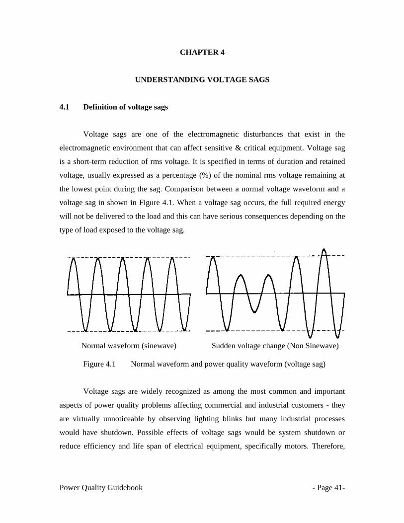
4.1 Definition of voltage sags
Voltage sags are one of the electromagnetic disturbances that exist in the
electromagnetic environment that can affect sensitive & critical equipment. Voltage sag
is a short-term reduction of rms voltage. It is specified in terms of duration and retained
voltage, usually expressed as a percentage (%) of the nominal rms voltage remaining at
the lowest point during the sag. Comparison between a normal voltage waveform and a
voltage sag in shown in Figure 4.1. When a voltage sag occurs, the full required energy
will not be delivered to the load and this can have serious consequences depending on the
type of load exposed to the voltage sag.
Normal waveform (sinewave)
Sudden voltage change (Non Sinewave)
Figure 4.1 Normal waveform and power quality waveform (voltage sag)
Voltage sags are widely recognized as among the most common and important
aspects of power quality problems affecting commercial and industrial customers - they
are virtually unnoticeable by observing lighting blinks but many industrial processes
would have shutdown. Possible effects of voltage sags would be system shutdown or
reduce efficiency and life span of electrical equipment, specifically motors. Therefore,
Power Quality Guidebook - Page 42-
such disturbances are particularly problematic for industry where the malfunction of a
device may result in huge financial losses
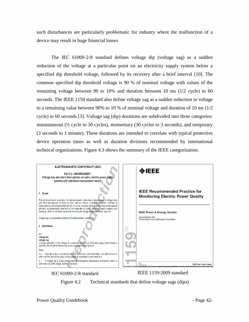
The IEC 61000-2-8 standard defines voltage dip (voltage sag) as a sudden
reduction of the voltage at a particular point on an electricity supply system below a
specified dip threshold voltage, followed by its recovery after a brief interval [10]. The
common specified dip threshold voltage is 90 % of nominal voltage with values of the
remaining voltage between 90 to 10% and duration between 10 ms (1/2 cycle) to 60
seconds. The IEEE 1159 standard also define voltage sag as a sudden reduction in voltage
to a remaining value between 90% to 10 % of nominal voltage and duration of 10 ms (1/2
cycle) to 60 seconds [3]. Voltage sag (dip) durations are subdivided into three categories:
instantaneous (½ cycle to 30 cycles), momentary (30 cycles to 3 seconds), and temporary
(3 seconds to 1 minute). These durations are intended to correlate with typical protective
device operation times as well as duration divisions recommended by international
technical organizations. Figure 4.3 shows the summary of the IEEE categorization.
IEC 61000-2-8 standard
IEEE 1159:2009 standard
Figure 4.2 Technical standards that define voltage sags (dips)

Power Quality Guidebook - Page 43-
Figure 4.3 Definitions of voltage sags, swells & transients (IEEE 1159:2009)
4.1.1 Understanding the voltage sag information in TNB PQ SMS
Voltage sag (%): 62.8 %, 88.3%. 88.4 %
Duration (ms): 71 40 38
Types: Sag Sag Sag
All the voltage sag values are less than 90 %
from the nominal voltage (100%), and
duration less than 60s.
Figure 4.4 Examples of SMS on voltage sags received from TNB.

Power Quality Guidebook - Page 44-
Voltage sag (%): 88.5 %, 56.9%. 88.4 %
Duration (ms): 4 59 18
Types: Sag Sag Sag
All the voltage sag values are less than 90 %
from the nominal voltage (100%), and
duration less than 60s.
Figure 4.5 Examples of SMS on voltage sags received from TNB.
4.2 Difference between voltage sag and voltage dip
Voltage sags or dips which are the same thing are brief reductions in voltage,
typically lasting from a cycle to a second or so, or tens of milliseconds to hundreds of
milliseconds. The term voltage sag has been used in the power quality community for
many years to describe a specific type of power quality disturbance - a short duration
voltage decrease. The IEC definition for this phenomenon is voltage dip. The two terms
are considered to be interchangeable. Generally, the term voltage sag is preferred in the
United States of America (USA) and the term voltage dip is common in European
countries.
Terminology used to describe the magnitude of voltage sag is often confusing.
According to IEEE 1159-2009, the recommended usage is ―a sag to 70%‖, which means
that the line voltage is reduced down to 70% of the normal value, not reduced by 70%.
This preference is consistent with IEC practice, and with most disturbance analyzers that
report remaining voltage. Just as an unspecified voltage designation is accepted to mean
Power Quality Guidebook - Page 45-
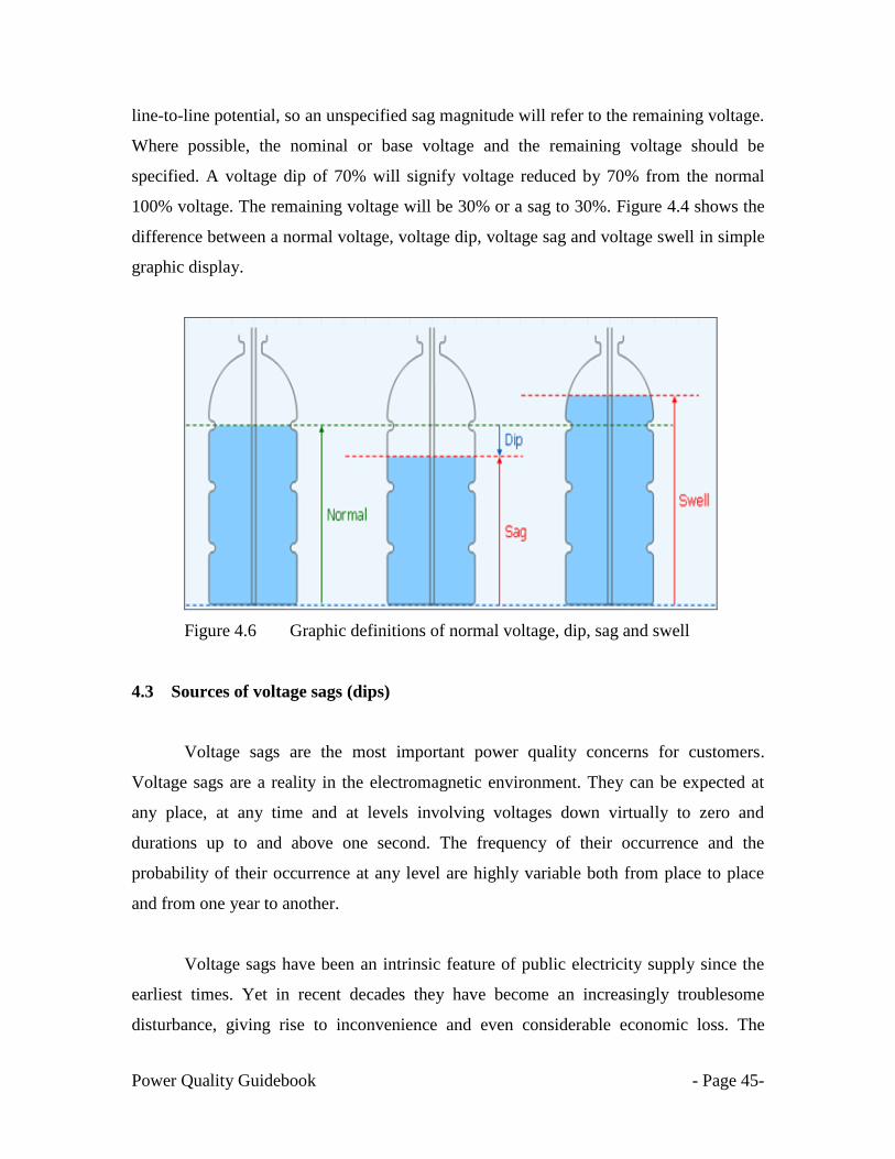
line-to-line potential, so an unspecified sag magnitude will refer to the remaining voltage.
Where possible, the nominal or base voltage and the remaining voltage should be
specified. A voltage dip of 70% will signify voltage reduced by 70% from the normal
100% voltage. The remaining voltage will be 30% or a sag to 30%. Figure 4.4 shows the
difference between a normal voltage, voltage dip, voltage sag and voltage swell in simple
graphic display.
Figure 4.6 Graphic definitions of normal voltage, dip, sag and swell
4.3 Sources of voltage sags (dips)
Voltage sags are the most important power quality concerns for customers.
Voltage sags are a reality in the electromagnetic environment. They can be expected at
any place, at any time and at levels involving voltages down virtually to zero and
durations up to and above one second. The frequency of their occurrence and the
probability of their occurrence at any level are highly variable both from place to place
and from one year to another.
Voltage sags have been an intrinsic feature of public electricity supply since the
earliest times. Yet in recent decades they have become an increasingly troublesome
disturbance, giving rise to inconvenience and even considerable economic loss. The
Power Quality Guidebook - Page 46-
reason is that some modern electricity utilisation equipment, either in its own design or
because of control features incorporated in it, has become more sensitive to voltage sags.
Voltage sags are inevitable on the power system [11]. The most important of these
variations occur during fault conditions on the power system. Since it is impossible to
eliminate the occurrence of faults, there will always be voltage variations. This chapter
will describe some of the concerns associated with short duration voltage sags. Voltage
swells can also be associated with fault conditions but these short duration overvoltages
are usually not severe and problems are uncommon.
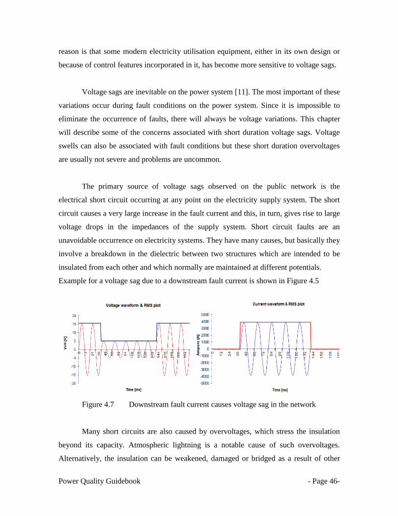
The primary source of voltage sags observed on the public network is the
electrical short circuit occurring at any point on the electricity supply system. The short
circuit causes a very large increase in the fault current and this, in turn, gives rise to large
voltage drops in the impedances of the supply system. Short circuit faults are an
unavoidable occurrence on electricity systems. They have many causes, but basically they
involve a breakdown in the dielectric between two structures which are intended to be
insulated from each other and which normally are maintained at different potentials.
Example for a voltage sag due to a downstream fault current is shown in Figure 4.5
Figure 4.7 Downstream fault current causes voltage sag in the network
Many short circuits are also caused by overvoltages, which stress the insulation
beyond its capacity. Atmospheric lightning is a notable cause of such overvoltages.
Alternatively, the insulation can be weakened, damaged or bridged as a result of other

Power Quality Guidebook - Page 47-
weather effects, by the impact or contact of animals, vehicles, excavating equipment, etc.,
and as a result of deterioration with age.
At the point of the short circuit, the voltage effectively collapses near to zero.
Simultaneously, at almost every other point on the system the voltage is reduced to the
same or, more generally, a lesser extent. Supply systems are equipped with protective
devices to disconnect the short circuit from the source of energy. As soon as that
disconnection takes place, there is an immediate recovery of the voltage, approximately
to its previous value, at every point except those disconnected. Some faults are self-
clearing: the short circuit disappears and the voltage recovers before disconnection can
take place.
The sudden reduction of voltage, followed by voltage recovery, as just described,
is the phenomenon known as voltage sag. The switching of large loads, the starting of
large motors and the fluctuations of great magnitude that are characteristic of some loads
can all produce large changes in current similar in effect to a short circuit current.
Although the effect is generally less severe at the point of occurrence, the resulting
changes in voltage observed at certain locations can be indistinguishable from those
arising from short circuits. In that case they also are categorised as voltage sags.
Examples of causes of voltage sags are shown in Figure 4.8 to Figure 4.16.
Conductor damaged due to a kite
Road work damaged underground cable
Figure 4.8 Examples of causes of voltage sags due to external events (1)

Power Quality Guidebook - Page 48-
Forest/Bush fire Crane encroachment
Figure 4.9 Examples of causes of voltage sags due to external events (2)
Crane encroachment
Metal thefts at transmission towers
Figure 4.10 Examples of causes of voltage sags due to external events (3)
Copper theft in distribution substation
Lightning
Figure 4.11 Examples of causes of voltage sags due to external disturbances (4)

Power Quality Guidebook - Page 49-
Transformer short circuited
Cable fault at customer‘s installations
Figure 4.12 Causes of voltage sags due to equipment failure at customers‘ premises (1)
Flashover in switchgear
Flashover in switchgear
Figure 4.13 Causes of voltage sags due to equipment failure at customers‘ premises (2)
Power Quality Guidebook - Page 50-
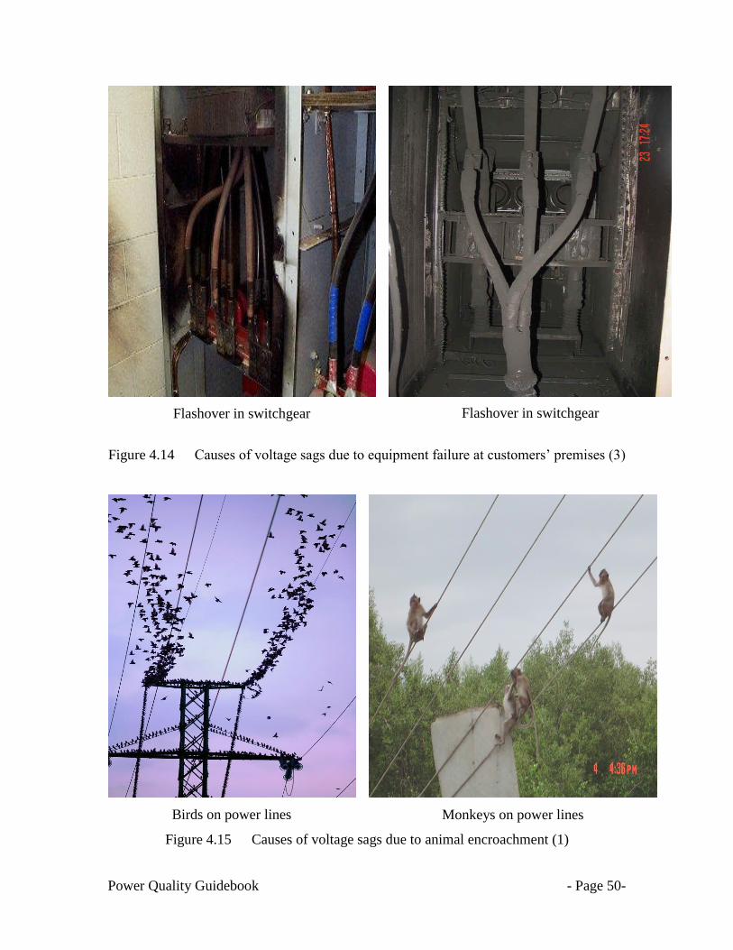
Flashover in switchgear
Flashover in switchgear
Figure 4.14 Causes of voltage sags due to equipment failure at customers‘ premises (3)
Birds on power lines
Monkeys on power lines
Figure 4.15 Causes of voltage sags due to animal encroachment (1)

Power Quality Guidebook - Page 51-
Snake on transmission tower
Birds on power lines
Figure 4.16 Causes of voltage sags due to animal encroachment (2)
4.4 Classification of voltage sags
There are two common classification methods for voltage sags:
Classification using a voltage sags magnitude and duration (ms)
Professor Math Bollen‘s classification .i.e. ABC classification. [12]
According to IEC-61000-4-30 [13], a voltage sag event is characterized by its magnitude,
which is the lowest rms voltage during the event, and its duration, which is the time that
the rms voltage stays below the threshold. Thus, the sag magnitude is the retained voltage
during the voltage sag. The voltage sag duration depends on the fault clearing time. As
the rms value of the voltage cannot change sharply, it is necessary to set a threshold,
below which the duration starts to be measured. The voltage sag duration stops when the
rms value is above the threshold again.

Power Quality Guidebook - Page 52-
Voltage sag types are generally based on the individual voltages (both magnitude and
angle) for each of the three phases during sags or dips [12]. Usually, three-phase voltage
sags are categorized by either the ABC classification or the symmetrical components
classification. However, voltage sag type according to the ABC classification is
frequently used due to its simplicity as it is based on a simplified network model.
Consequently, the classification is based on incomplete assumptions and cannot be used
to obtain the characteristics of measured sags. The symmetrical component classification
is more general and gives a direct link with measured voltages but is harder to understand
and a translation to the ABC classification may be suitable for many applications. In
addition, the ABC classification was developed to analyze the propagation of sag or dip
from transmission to distribution levels, when a disturbance propagates through a
transformer. Table 4.1 & Figure 4.17 give brief overviews of the different types of
voltage sags, associated faults and waveforms.
Table 4.1 Different sag types and their associated faults
Type of voltage sag Type of fault
Type A Three-phase
Type B Single-phase to ground
Type C Phase to phase
Type D
Phase-to-phase fault (experienced by a
delta connected load), single-phase to
ground (zero sequence component
removed)
Type E Two-phase-to-phase fault (experienced by
a Wye connected load)
Type F Two-phase-to-phase fault (experienced by
a delta connected load)
Type G
Two-phase to phase fault (experienced by
a load connected via a non-grounded
transformer removing the zero sequence
component)

Power Quality Guidebook - Page 53-
Figure 4.17 Voltage Sag Types - ABC Classification
Note: Before fault (single line) and during fault (solid line).
Power Quality Guidebook - Page 54-
4.4.1 Factors that affect voltage sag type [14]
Specifically, at the equipment terminals, these factors affect the voltage sag type:
Fault type
Voltage sags are primarily caused by system faults. Each fault type has a different effect
to the voltages at the fault point, which subsequently defined the voltage sag types.
o Single-Line-to-Ground Fault
o Line-to-Line Fault
o Double-Line-to-Ground Fault
o Three Phase Fault
Transformer Winding Connection
Transformer winding connections are classified into three types to explain the transfer of
three-phase unbalanced voltage sags, as well as the change in voltage sag type, from one
voltage level to another.
Type 1 – Transformers that do not change anything to the voltages. The
primary voltages (per unit) are equal to the secondary (per unit) voltages. The
only transformer configuration that falls under this type is the WYE
Grounded-wye grounded (YNyn).
Type 2 – Transformers that remove the zero-sequence voltage. Basically, the
secondary voltage (per unit) is equal to the primary voltage (per unit) minus
the zero-sequence component. The DELTA-delta (Dd), DELTA-zigzag (Dz)
and the WYE-wye (with both windings ungrounded or with only one star
point grounded) belong to this type.
Type 3 – Transformers that changes line and phase voltages. DELTA-wye
(Dyn), WYE-delta (YNd) and the WYE-zigzag (YNz) fit under this type.

Power Quality Guidebook - Page 55-
Details on transformers vector groups are shown in Table 4.2
Table 4.2 Common transformer connections and vector groups [15].

Power Quality Guidebook - Page 56-
Types of Load Connection
o Wye-connected load
o Delta-connected load
Figure 4.18 Star & Delta connections of three phase loads
4.5 Propagation of voltage sags.
The observed voltage sag magnitude arising from a particular causative event
depends on whether the observation point and the event are on the same or different sides
of a network or customer transformer. The phasing of the short circuit or other event, the

Power Quality Guidebook - Page 57-
phasing of the measurement system, and the connection methods of the primary and
secondary transformer windings are all significant in this regard. For instance,
considering the network or installations on either side of a step down transformer
connected Dyn, a single line to ground fault can result, on the primary side, in a voltage
dip of 0 V (residual voltage) on one phase, but, on the secondary side, a line to neutral
voltage on two phases of 58% of the pre-existing voltage [10].
In practice, loads that are sensitive to voltage sags are often connected line-to-line
in industrial installations. They would therefore be subjected to line-to-line voltage dips
rather than line-to-neutral dips. This needs to be taken into account in considering
whether measurements are conducted line-to-neutral, line to-line, or both.
Overall, the types of voltage sags and the transformation to lower voltage levels,
for all seven types of three-phase unbalanced sags, are summarized in Tables 4.3 and 4.4.
Table 4.3 Transformation of voltage sag type to lower voltage level (after transformer)
Connection Sag on primary side
Type A Type B Type C Type D Type E Type F Type G
Ynyn A B C D E F G
Yy, Dd, Dz A D C D G F G
Yd, Dy, Yz A C D C F G F
Table 4.4 Transformation of voltage sag type to lower voltage level (Load connection)
Fault Type Load Connection
Star Delta
Three phase A A
Two phase to ground E F
Phase to phase C D
Single phase B C

Power Quality Guidebook - Page 58-
4.6 Impact of voltage sags to industrial equipment
Today‘s factory floors usually include a proliferation of sensitive electronics, such
as programmable logic controllers (PLCs), variable-frequency drives (VFDs), and
network communications devices, all of which have led to tremendous gains in
productivity. Ironically, however, many of these same electronic devices also contribute
to productivity losses because of their sensitivity to voltage sags, swells, and transients.
These electronic equipments, which are now so integral to industrial and
commercial power systems, can fail or malfunction if subjected to a voltage, current, or
frequency deviation. Before the era of solid-state electronics, power quality was not
discussed because it had little or no effect on most loads connected to electrical
distribution systems. When an induction motor suffered a voltage sag, it did not shut
itself down but simply "spun out" fewer horsepower until the sag ended. The same was
true for incandescent or fluorescent lighting systems in a facility-the lumen output just
decreased temporarily.
The most common failure mechanism is lack of energy. This can manifest itself in
something as simple as insufficient voltage to keep a critical relay or contactor energized
or something as complex as an electronic sensor with a failing power supply giving an
incorrect reading, which would cause essential equipment to react inappropriately.
But today, as sensitive equipment and processes become more complex and
downtime costs increase, contractors and engineers have to specify and install specialized
equipment to avoid undesirable situations. The ideal power-supply voltage for sensitive
electronic equipment is an uninterrupted sinusoidal waveform of constant amplitude. Any
event that compromises this condition is called a power quality disturbance. Power
quality disturbances as brief as one-half cycle can affect the operation of sensitive
electronic equipment.
Power Quality Guidebook - Page 59-
4.6.1 Impact of voltage sags to electronic equipment
Electronic devices require a more controlled electrical environment than most other
loads. This is especially true when it comes to the input voltage. If the voltage of the
power supply varies beyond the specifications of the device, then problems can occur.
Recall that a voltage sag is not simply a change in the rms magnitude, but a change over a
discrete period of time. This time interval is important in terms of determining acceptable
voltage. The fundamental issue behind the symptoms related to voltage sags is how much
energy is being transferred into the power supply. If inadequate energy is going into the
power supply due to voltage sag, then the dc voltage applied to the integrated circuits
drops. If this happens, the device will shut down, lock up, or garble data. If the device
shuts down, it will usually restart as soon as enough energy gets back into the supply. On
the other hand, if too much energy goes into the supply because of a voltage swell, it will
probably cause damage. Blown power supplies are the most common result of large
swells. Obviously, if the power supply fails then the whole device goes down.
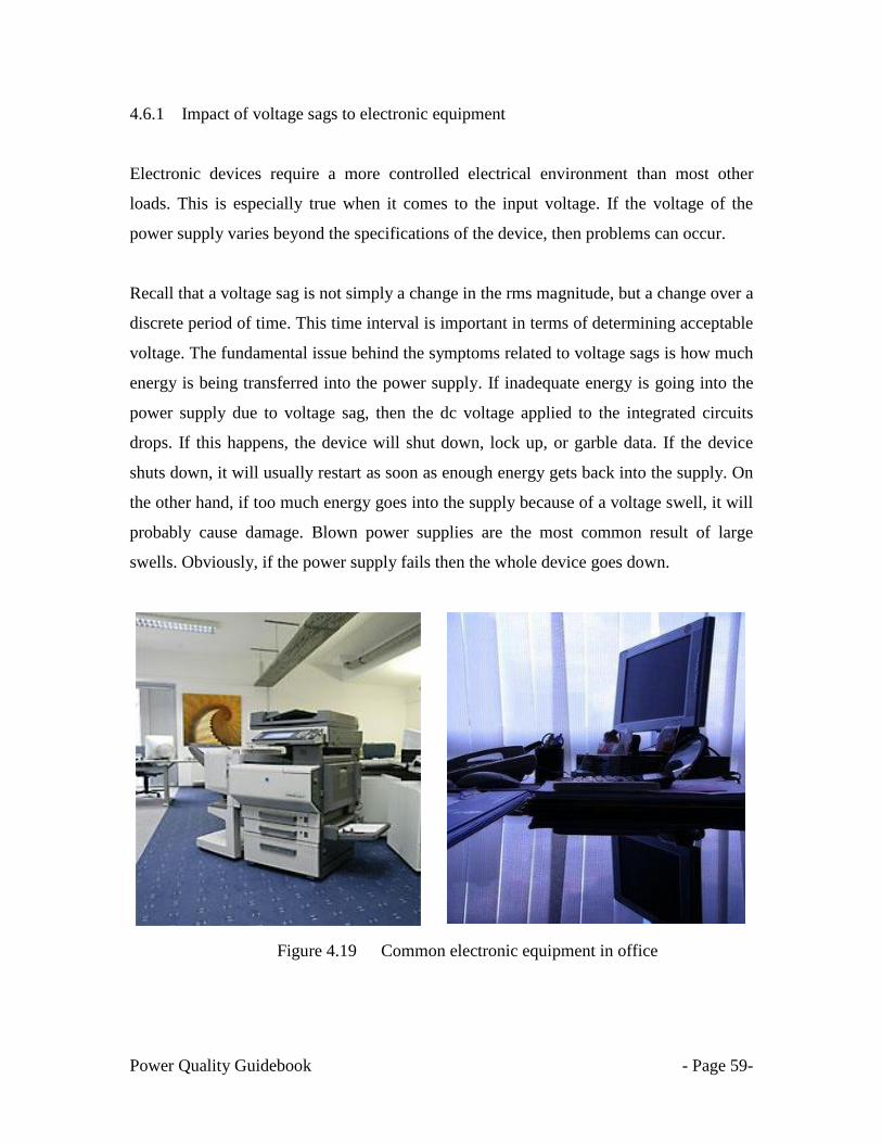
Figure 4.19 Common electronic equipment in office
Power Quality Guidebook - Page 60-
4.6.2 Sensitive equipment in industrial plants
Voltage sags and swells give severe impact to the industrial customer‘s equipment. Truly
severe swells may stress components to the point of failure, but other than that there is
seldom disruption or damage. Problems may arise as the system responds to the reaction
of the load to the sag or swell. It is possible that if a sag or swell is extreme enough and
lasts long enough, the resultant over current could trip breakers, blow fuses or damage the
electronic components.
Sensitivity of adjustable speed drives (ASDs) to voltage sags is usually expressed as a
voltage tolerance curve, in terms of only one pair of sag magnitude/duration values.
These two values are denoted as the threshold values – if the voltage sag is longer than
the specific duration threshold and deeper than the specific voltage magnitude threshold,
the ASD will malfunction/trip. For ASDs, reported threshold values vary from 50-60% to
80-90% of rated voltage for magnitude and from 1/2 cycle (or even less) up to 5-6 cycles
for the duration [16].
4.6.3 Impact of voltage sags to motors
Motors are extremely tolerant to voltage sags and voltage swells. Unless the rms
magnitudes are either very low or very high, motors typically have little response to these
voltage variations. Keep in mind that if the motors are controlled by electronic drive
controllers, the discussion on electronic equipment applies. If the magnitudes are
extreme, or if these disturbances occur frequently, then several symptoms may develop.
First, extreme swells will electrically stress the windings on the stator. This leads to
premature motor failure. Second, extreme sags may cause the motor to lose enough
rotational inertia to affect its performance or task. Third and last, if sags happen
frequently enough, the motor may draw high inrush currents often enough to trip a
breaker.

Power Quality Guidebook - Page 61-
4.6.4 Impact of voltage sags to lighting systems
Most lighting systems are tolerant of voltage sags and voltage swells. Incandescent
systems will simply burn brighter or dimmer. Overall life expectancy may be affected,
and the change in brightness may be annoying, but no other adverse reactions usually
occur. This change in brightness is often called "flicker."
Figure 4.20 General lighting facilities
Fluorescent systems may not fare quite as well. Standard ballasts are typically
more tolerant than electronic ballasts. In both cases there may be some flicker, but the
real concerns are with restarts and reliability. If voltage sags are deep enough, then the
ballast will no longer be able to provide the energy needed to generate the arc inside the
fluorescent tube. This means a dark lamp. If swells are extreme, then the ballast is
stressed, causing premature failure.
High intensity discharge, or HID lighting such as mercury vapor, metal halide,
and high and low pressure sodium lights are also more sensitive to sags and swells. While
their response is very similar to electronic fluorescent ballasts, the lamps themselves are
typically more sensitive than the ballasts. A common problem is HID systems turning off
during voltage sag. Sodium discharge lamps have a much higher striking voltage when
hot than cold, so that a hot lamp may not restart after a dip. Unlike fluorescent systems

Power Quality Guidebook - Page 62-
that will quickly turn back on, the HID system must wait several minutes (10-15 minutes)
before being restarted. This is not only annoying but can be dangerous.
Figure 4.21 High intensity discharge lamps
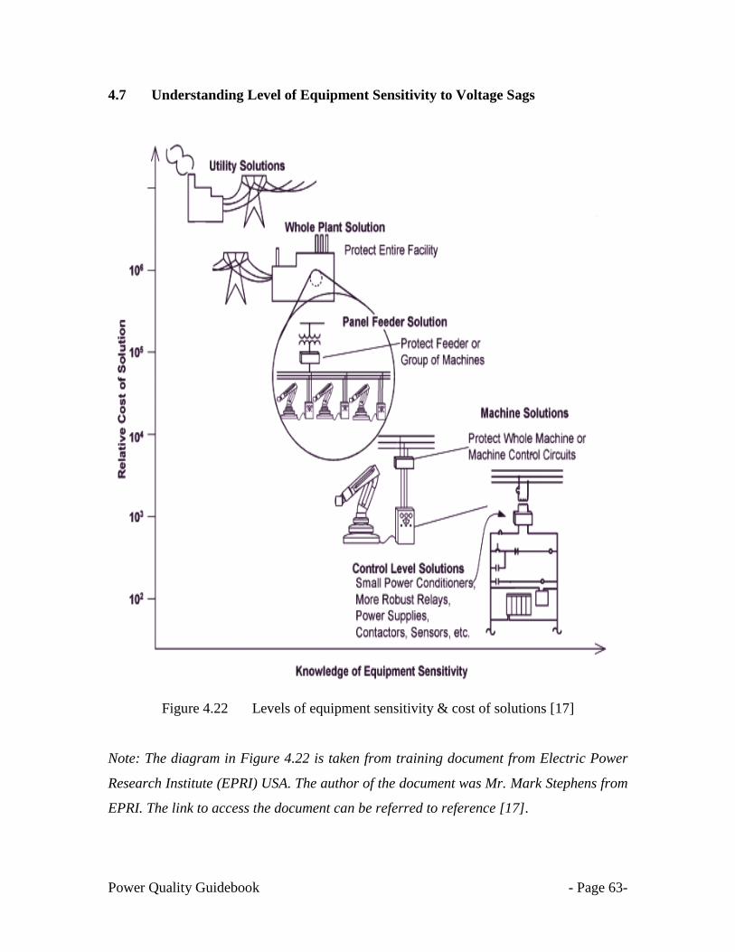
Power Quality Guidebook - Page 63-
4.7 Understanding Level of Equipment Sensitivity to Voltage Sags
Figure 4.22 Levels of equipment sensitivity & cost of solutions [17]
Note: The diagram in Figure 4.22 is taken from training document from Electric Power
Research Institute (EPRI) USA. The author of the document was Mr. Mark Stephens from
EPRI. The link to access the document can be referred to reference [17].

Power Quality Guidebook - Page 64-
4.7.1 Understanding control level sensitivity to voltage sag
Figure 4.23 General control level equipment & solutions
As with all disturbance phenomena, the gravity of the effects of voltage sags and
short interruptions depends not only on the direct effects on the equipment concerned, but
also on how important and critical is the function carried out by that equipment. For
example, modern manufacturing methods often involve complex continuous processes
utilizing many devices acting together.
A failure or removal from service of any one device, in response to a voltage sag
or short interruption can necessitate stopping the entire process, with the consequence of
loss of product and damage or serious fouling of equipment. This can be one of the most
serious and expensive consequences of voltage sags and short interruptions. Such
consequential damage or loss, however, is a function of the design of the process and is
an indirect or secondary effect of the voltage dip or short interruption.
Process machines comprised of common electrical components used in all types
of processes. Since fundamental control components are used in every type of equipment,
a basic understanding of their response to voltage sags can help designer build and
service a more reliable machine. The basic control level equipment components normally
used in industrial plants are:-
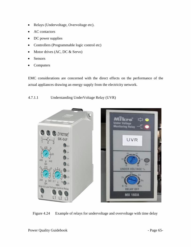
Power Quality Guidebook - Page 65-
Relays (Undervoltage, Overvoltage etc).
AC contactors
DC power supplies
Controllers (Programmable logic control etc)
Motor drives (AC, DC & Servo)
Sensors
Computers
EMC considerations are concerned with the direct effects on the performance of the
actual appliances drawing an energy supply from the electricity network.
4.7.1.1 Understanding UnderVoltage Relay (UVR)
Figure 4.24 Example of relays for undervoltage and overvoltage with time delay
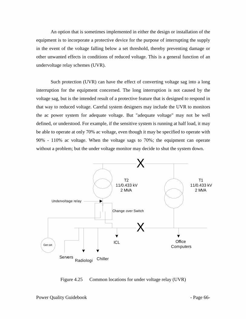
Power Quality Guidebook - Page 66-
An option that is sometimes implemented in either the design or installation of the
equipment is to incorporate a protective device for the purpose of interrupting the supply
in the event of the voltage falling below a set threshold, thereby preventing damage or
other unwanted effects in conditions of reduced voltage. This is a general function of an
undervoltage relay schemes (UVR).
Such protection (UVR) can have the effect of converting voltage sag into a long
interruption for the equipment concerned. The long interruption is not caused by the
voltage sag, but is the intended result of a protective feature that is designed to respond in
that way to reduced voltage. Careful system designers may include the UVR to monitors
the ac power system for adequate voltage. But "adequate voltage" may not be well
defined, or understood. For example, if the sensitive system is running at half load, it may
be able to operate at only 70% ac voltage, even though it may be specified to operate with
90% - 110% ac voltage. When the voltage sags to 70%; the equipment can operate
without a problem; but the under voltage monitor may decide to shut the system down.
Figure 4.25 Common locations for under voltage relay (UVR)
T1
11/0.433 kV
2 MVA
T2
11/0.433 kV
2 MVA
X
X
Change over Switch
Chiller
ICL
Radiologi
Gen setOffice
Computers
Servers
Undervoltage relay

Power Quality Guidebook - Page 67-
4.7.1.2 Understanding contactors
A contactor is another name for an electrical relay. It is a device that allows a low current
(normal) switch to turn on or off high current equipment such as heaters or air-
conditioners that would be well beyond its capacity. Contactors are used extensively to
control large loads in an industrial plant. Contactors typically have multiple contacts, and
those contacts are usually (but not always) normally open, so that power to the load is
shut off when the coil is de-energized. The most common industrial use for contactors is
the control of electric motors.
Figures 4.26, 4.27 & 4.28 show a typical contactor application.
Figure 4.26 A common contactor
M
COIL
Contactor
Auxiliarry
Contacts
Main
Contacts
Stop
Start
N R Y B

Power Quality Guidebook - Page 68-
Figure 4.27 General circuit for control circuit & contactor (1)
Figure 4.28 General circuit for control circuit & contactor (2)
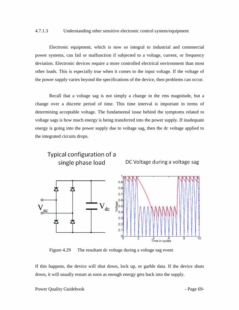
Power Quality Guidebook - Page 69-
4.7.1.3 Understanding other sensitive electronic control system/equipment
Electronic equipment, which is now so integral to industrial and commercial
power systems, can fail or malfunction if subjected to a voltage, current, or frequency
deviation. Electronic devices require a more controlled electrical environment than most
other loads. This is especially true when it comes to the input voltage. If the voltage of
the power supply varies beyond the specifications of the device, then problems can occur.
Recall that a voltage sag is not simply a change in the rms magnitude, but a
change over a discrete period of time. This time interval is important in terms of
determining acceptable voltage. The fundamental issue behind the symptoms related to
voltage sags is how much energy is being transferred into the power supply. If inadequate
energy is going into the power supply due to voltage sag, then the dc voltage applied to
the integrated circuits drops.
Figure 4.29 The resultant dc voltage during a voltage sag event
If this happens, the device will shut down, lock up, or garble data. If the device shuts
down, it will usually restart as soon as enough energy gets back into the supply.
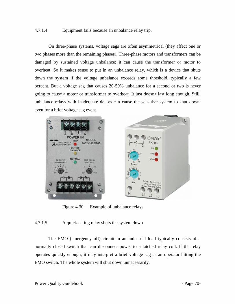
Power Quality Guidebook - Page 70-
4.7.1.4 Equipment fails because an unbalance relay trip.
On three-phase systems, voltage sags are often asymmetrical (they affect one or
two phases more than the remaining phases). Three-phase motors and transformers can be
damaged by sustained voltage unbalance; it can cause the transformer or motor to
overheat. So it makes sense to put in an unbalance relay, which is a device that shuts
down the system if the voltage unbalance exceeds some threshold, typically a few
percent. But a voltage sag that causes 20-50% unbalance for a second or two is never
going to cause a motor or transformer to overheat. It just doesn't last long enough. Still,
unbalance relays with inadequate delays can cause the sensitive system to shut down,
even for a brief voltage sag event.
Figure 4.30 Example of unbalance relays
4.7.1.5 A quick-acting relay shuts the system down
The EMO (emergency off) circuit in an industrial load typically consists of a
normally closed switch that can disconnect power to a latched relay coil. If the relay
operates quickly enough, it may interpret a brief voltage sag as an operator hitting the
EMO switch. The whole system will shut down unnecessarily.
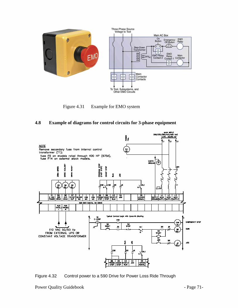
Power Quality Guidebook - Page 71-
Figure 4.31 Example for EMO system
4.8 Example of diagrams for control circuits for 3-phase equipment
Figure 4.32 Control power to a 590 Drive for Power Loss Ride Through

Power Quality Guidebook - Page 72-
Examples of typical diagrams for control circuits for compressor and chillers are shown
in Figure 4.33 & 4.34.
Figure 4.33 Diagrams for control circuits for compressor

Power Quality Guidebook - Page 73-
Figure 4.34 Diagrams for control circuits for chillers

Power Quality Guidebook - Page 74-
CHAPTER 5
MONITORING VOLTAGE SAGS
5.1 INTRODUCTION
Electricity at the wall outlet is an electromagnetic phenomenon. Electrical power
is provided as alternating current (ac), a silent, seemingly limitless source of energy that
can be generated at power stations, boosted by transformers, and delivered over hundreds
of miles to any location in the region. Seeing what this energy is doing in small slices of
time can provide an understanding of how important simple, smooth ac power is to
reliable operation of the sophisticated systems that we are dependent upon.
An oscilloscope allows one to see what this energy looks like. In a perfect world,
commercial ac power appears as a smooth, symmetrical sine wave, varying at either 50 or
60 cycles every second (Hz) depending on which part of the world you‘re in. Figure 5.1
shows what an ac voltage sine wave would appear in an oscilloscope.
Figure 5.1 Oscilloscope: Image of an ac voltage sine wave

Power Quality Guidebook - Page 75-
The sinusoidal wave shape shown above represents a voltage changing from a
positive value to a negative value, 50 times per second. When this flowing wave shape
changes size, shape, symmetry, frequency, or develops notches, impulses, ringing, or
drops to zero (however briefly), there is a electrical power disturbance.
PQ or voltage incidents are often momentary occurring in a fraction of a cycle and
are very hard to observe or diagnose without any proper tool. PQ disturbances can also be
very high-speed events such as voltage impulses / transients, high frequency noise, wave
shape faults, voltage swells and sags and total power loss. Each type of electrical
equipment will be affected differently by these PQ issues. We can only verify the power
PQ disturbances by installing a special type of high-speed recording equipment to
monitor the electrical power.
Power quality (PQ) monitoring is a rewarding initiative for power utilities since it
enables continuous monitoring of the power supply and early detection of
electromagnetic disturbances. The PQ data will enable engineers to perform root cause
analysis and take timely corrective actions to improve overall the power system
reliability. PQ monitoring is also of interest to major energy consumers as they also want
to avoid expensive equipment failures. Therefore, mutual interest of energy suppliers and
energy consumers in PQ monitoring motivates the use of high performance PQ
monitoring instruments.
Another important aspect in PQ monitoring is the collection of information
regarding the performance of a power system in terms of voltage sag and interruption.
Modern PQ monitoring systems now also provide the added benefit of simultaneously
monitoring demand, energy and other parameters.

Power Quality Guidebook - Page 76-
5.2 Power Quality Monitoring
As defined in Chapter 1, PQ disturbances can be classified as:-
short duration disturbances (Sags, Swells & Transients)
continuous & steady state disturbances (harmonics, notches, flickers, unbalance)
The short duration PQ disturbances are momentary occurring in a fraction of a cycle and
are very hard to observe or diagnose without any proper tool. The continuous and steady
state PQ disturbances are voltage waveforms that are not perfectly sinusoidal but
continuous or in a steady state conditions. Examples of the steady state PQ disturbances
are shown in figures 5.2 to 5.7.
Figure 5.2 Changes in the reactive power and the resulting voltage fluctuations
at the point of connection of an arc furnace
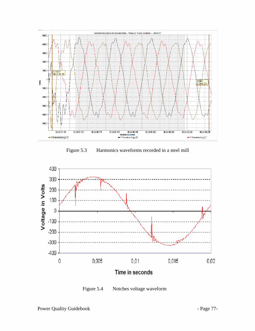
Power Quality Guidebook - Page 77-
Figure 5.3 Harmonics waveforms recorded in a steel mill
Figure 5.4 Notches voltage waveform
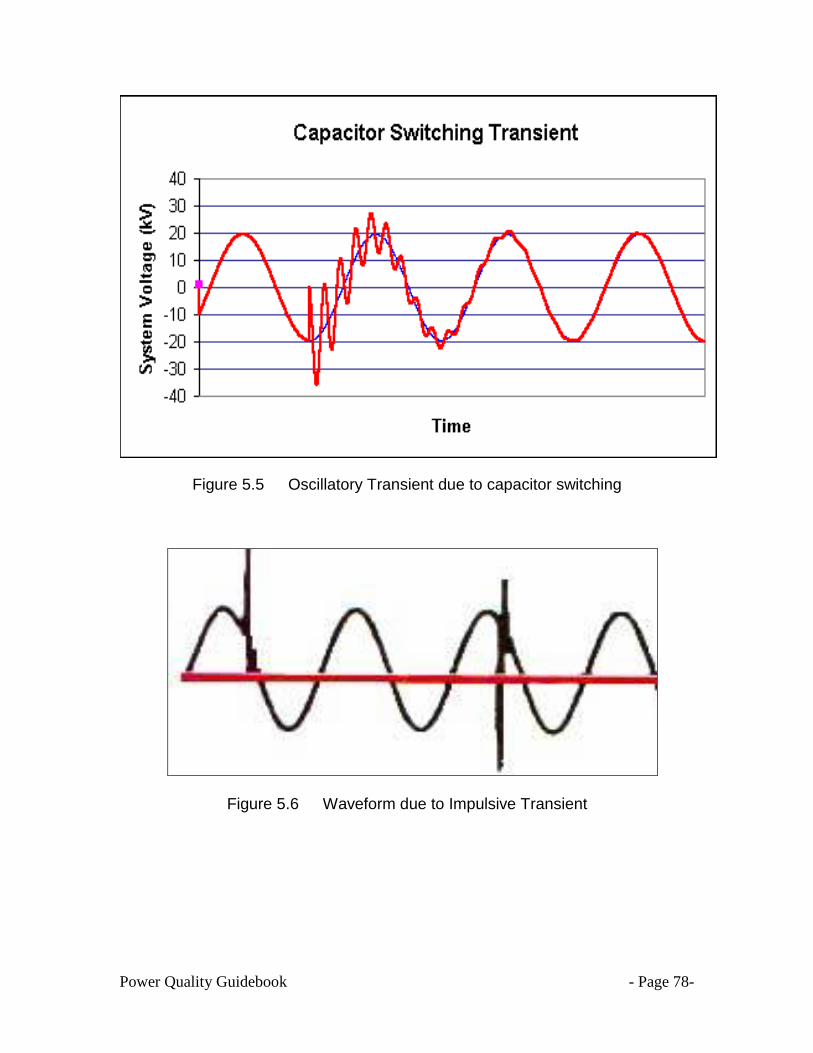
Power Quality Guidebook - Page 78-
Figure 5.5 Oscillatory Transient due to capacitor switching
Figure 5.6 Waveform due to Impulsive Transient
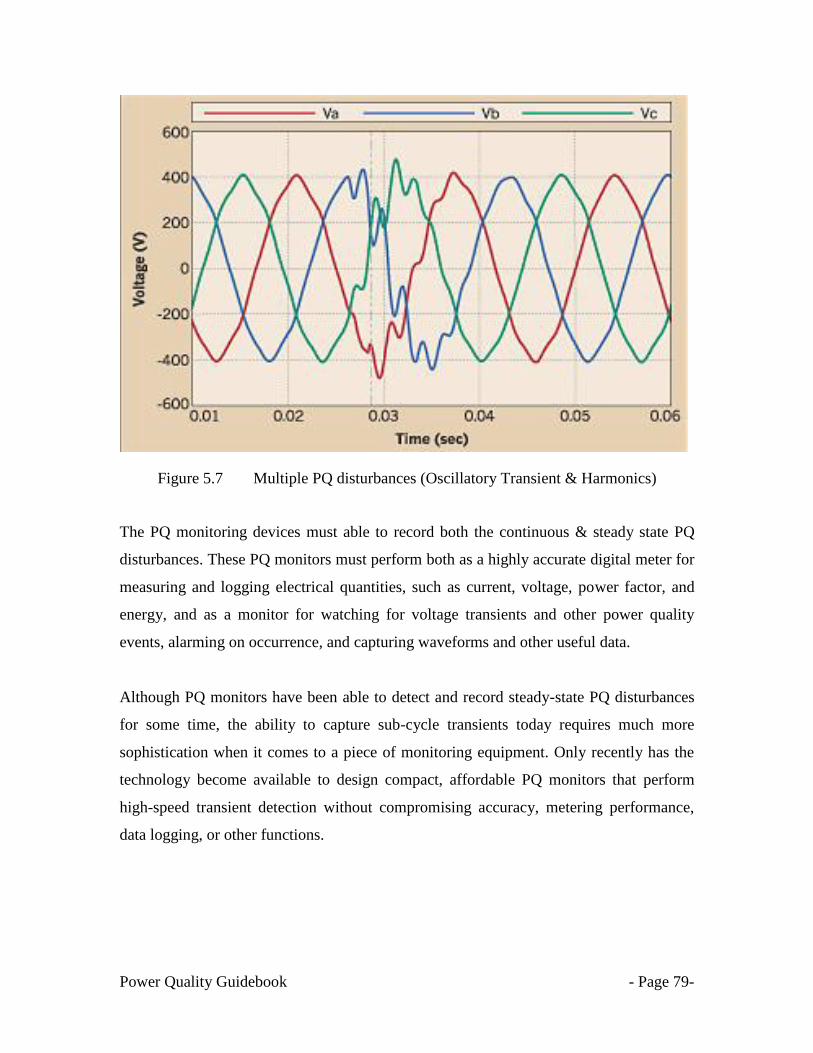
Power Quality Guidebook - Page 79-
Figure 5.7 Multiple PQ disturbances (Oscillatory Transient & Harmonics)
The PQ monitoring devices must able to record both the continuous & steady state PQ
disturbances. These PQ monitors must perform both as a highly accurate digital meter for
measuring and logging electrical quantities, such as current, voltage, power factor, and
energy, and as a monitor for watching for voltage transients and other power quality
events, alarming on occurrence, and capturing waveforms and other useful data.
Although PQ monitors have been able to detect and record steady-state PQ disturbances
for some time, the ability to capture sub-cycle transients today requires much more
sophistication when it comes to a piece of monitoring equipment. Only recently has the
technology become available to design compact, affordable PQ monitors that perform
high-speed transient detection without compromising accuracy, metering performance,
data logging, or other functions.
Power Quality Guidebook - Page 80-
To ensure correct recording of PQ disturbances, the PQ device must have the following
features:-
Fast sample rate. The required sample rate depends on the frequency of the
transients. Since most low-and medium-frequency oscillatory transients occur in
the kilohertz frequency range, circuit monitors that sample voltage input channels
at 128, 256 or 512 samples-per-cycle can occasionally detect and capture
oscillatory transients. On the other hand, impulsive transients are often shorter in
duration and require much higher sample rates.
A monitoring device that samples data at the rate of 512 samples-per-cycle can
sample data only once per 32.5 µsec. This is adequate for general disturbance
monitoring and some oscillatory transients, but it's far too slow to characterize a
1.2×50-µsec impulsive transient. PQ monitors with the fastest transient detection
capabilities sample voltage data at 5 MHz per voltage channel or 83,333 samples-
per-cycle, which is fast enough to detect even very short impulsive transients.
Ample onboard memory. The PQ monitor should be able to store multiple, high-
resolution captured waveforms and the associated rms data while still performing
data logging functions, such as load profiling and energy usage, for standard
monitoring purposes. It also should store transient waveform data in nonvolatile
memory to prevent data loss if the circuit monitor should lose control power.
Sag/swell alarms. The PQ monitor should support high-speed alarms with a
detection rate of less than half a cycle for capturing sag/swell disturbances. It's
also useful when this alarm operates output relays. Alarms should trigger a
waveform capture up to 60 cycles in duration; record the event in the circuit
monitor's onboard event log, including a date/time stamp and the rms magnitude
of the most extreme value of the sag or swell; and force the circuit monitor to log
other pertinent data in its onboard memory.

Power Quality Guidebook - Page 81-
Currently, there are two types of PQ monitoring devices. A handheld PQ meter can only
record steady state power system parameters and PQ disturbances in particular
harmonics. A full PQ monitor or PQ recorders can record the power system parameters
and both the short duration voltage disturbances and steady state PQ disturbances.
5.2.1 Understanding True RMS meter
A RMS multimeter True RMS voltage/current meter
Figure 5.2 RMS & True RMS clamp meters
A RMS clamp meter and a common RMS multimeter only record steady state
fundamental (50 Hz) data. The ‗Root Mean Square‘ magnitude of an alternating current is
the value of equivalent direct current that would produce the same amount of heat in a
fixed resistive load. For a perfect sinewave, the RMS value is 0.707 times the peak value
(or the peak value is √2, or 1.414, times the RMS value). This is the approach taken in all
analogue meters and in all older and most current, digital multimeters. This technique is
described as ‗mean reading, RMS calibrated‘ measurement. However, the RMS technique
only works for pure voltage waveform and will give an inaccurate value for non
sinusoidal voltage waveforms.
To overcome this inaccuracy, a True RMS meter is required. A true RMS meter
works by taking the square of the instantaneous value of the input current, averaging over

Power Quality Guidebook - Page 82-
time and then displaying the square root of this average. Perfectly implemented, this is
absolutely accurate whatever the waveform. There are two limiting factors to be taken
into account to the implement the True RMS measurement:- frequency response and crest
factor. True RMS measurement will give a higher ampere reading as compared to that of
a normal RMS meter.
True RMS measurement is essential in any installation where there is a significant
number of non-linear loads (ASD, Computers, electronic ballasts, compact fluorescent
lamps, etc.). A normal RMS meters will give an under measurement of up to 40 % which
can result in cables and circuit breakers being under rated with the risk of failure and
nuisance tripping.
5.2.2 Description of PQ recording equipment
We can only verify the existence of PQ disturbances by installing a special type of
high-speed recording equipment (PQ recorder) to monitor the electrical power. This type
of test equipment will provide information used in evaluating if the electrical power is of
sufficient quality to reliably operate the equipment.
The process is similar to a doctor using a heart monitor to record the electrical
signals for your heart. Monitoring will provide us with valuable data, however the data
needs to be interpreted and applied to the type of equipment being powered. The use of a
PQ recorder is also ‗similar‘ to the use of a stethoscope to hear irregular heart beat.
A medical device that is also used for recording heart rate is the ECG. ECG
(Electrocardiography) is used to measure the rate and regularity of heartbeats, as well as
the size and position of the chambers, the presence of any damage to the heart, and the
effects of drugs or devices used to regulate the heart, such as a pacemaker.

Power Quality Guidebook - Page 83-
Figure 5.3 Comparison : Equipment to evaluate power quality and heart beat
Equipment to record heart beat
Equipment to record power quality
Figure 5.4 Comparison : Equipment to monitor heart beat and power quality (1)

Power Quality Guidebook - Page 84-
Waveforms recorded by a
heart monitoring recorder
Waveforms recorded by a
power quality recorder
Figure 5.5 Comparison : Equipment to monitor heart beat and power quality (2)
Figure 5.6 Example on ECG monitoring and test results
ECG will provide us with valuable health data, however the recorded data needs to be
interpreted or diagnosed by a medical specialist. The graph in Figure 5.6 shows the
results of a stress test and can only be diagnosed by a the medical specialist.

Power Quality Guidebook - Page 85-
Likewise, PQ monitoring will provide us with valuable electrical data on the performance
of the power systems. A power quality monitoring will provide more data than a ECG
monitoring. The occurrence of a PQ events normally involves a drastic change in voltage
(a period of time <10 ms) that may disrupt the operation of equipment in factories.
PQ recorder brand B
PQ recorder brand C
Figure 5.7 Examples of PQ recorders
5.3 What to Monitor?
PQ monitoring at critical facilities must be done very details. The systems should
characterize steady state events (voltage regulation, unbalance, harmonics, flickers, ) as
well as disturbances (transients, voltage sags, voltage swells, interruptions, outages). PQ
events should be characterized with complete voltage and current waveform information
for evaluating interaction issues and the response of equipment that may be sensitive to
microsecond variations in the voltage.
5.4 Locations to monitor Power Quality
The selection of monitoring locations will depend on the facility design, critical
loads, power conditioning equipment, and the specific objectives of the monitoring. As a
minimum, the monitoring should include the utility supply locations, outputs of power
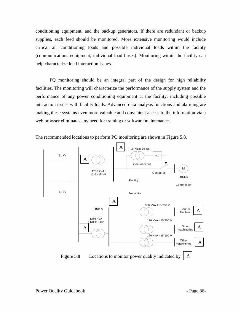
Power Quality Guidebook - Page 86-
conditioning equipment, and the backup generators. If there are redundant or backup
supplies, each feed should be monitored. More extensive monitoring would include
critical air conditioning loads and possible individual loads within the facility
(communications equipment, individual load buses). Monitoring within the facility can
help characterize load interaction issues.
PQ monitoring should be an integral part of the design for high reliability
facilities. The monitoring will characterize the performance of the supply system and the
performance of any power conditioning equipment at the facility, including possible
interaction issues with facility loads. Advanced data analysis functions and alarming are
making these systems even more valuable and convenient access to the information via a
web browser eliminates any need for training or software maintenance.
The recommended locations to perform PQ monitoring are shown in Figure 5.8.
Figure 5.8 Locations to monitor power quality indicated by
11 kV
1250 kVA
11/0.415 kV
11 kV
1250 kVA
11/0.415 kV
M
Control circuit
350 kVA 415/200 V
120 kVA 415/200 V
120 kVA 415/100 V
Sputter
Machine
Chiller
Other
machineries
Other
machineries
LINE 5
Contactor
240 Volt/ 24 DC
PLC
Compressor
Facility
Production
A
A
A
A
A
A
A
A

Power Quality Guidebook - Page 87-
5.5 Importance of having a good software to diagnose Power Quality
PQ recorder converts electrical current and voltage readings to graphic
representations called waveform signatures. All types of PQ disturbances such as voltage
sag, transient overvoltage and interruption can be identified by specific waveform
signatures. It is desirable to have a system that can automatically detect and classify all
PQ disturbances especially if the database is large. The data capturing is based on
triggering levels applied at the PQ recorder.
All types of voltage disturbances such as voltage sags, transient overvoltages,
interruptions, etc. can be identified by a specific signature/waveform. These
signatures/waveforms can help to solve PQ disturbance problems experienced by
customers. However, the amount of data recorded by the PQ recorder is vast and to a
layman the data provides little information related to the PQ disturbances. To analyze
manually all the PQ disturbances is a nontrivial task mainly due to the huge volume of
disturbance records. Therefore it is important to have a good software or technique that
can assist in the analysis of all the recorded PQ disturbances. The software should be user
friendly as to show displays for all the PQ disturbances in graphic and tabular data.
A good software must be a requirement for the PQ recorder, it's necessary to
annunciate alarms, view captured waveforms, store waveforms and related data to a disk,
and so on. Other useful features include the ability to view harmonic spectral plots and
rms plots, zoom on and overlay waveforms, and export waveforms in a standard file
format like excel, PQDIF etc.
Example of a typical software for power quality is shown in Figure 5.9.

Power Quality Guidebook - Page 88-
Figure 5.9 Example of a PQ analysis software
A good PQ software will enable one to diagnose the PQ waveforms and assist in the
preparation of a simple technical report.
Power Quality Guidebook - Page 89-
CHAPTER 6
EQUIPMENT COMPATIBILITY REQUIREMENT
6.1 POWER QUALITY DESIGN PHILOSOPHY
More recently, engineers around the world have realized that voltage sag is really
a compatibility problem with at least two classes of solutions: You can improve the
power or you can make the equipment tougher. The latter approach is called ―voltage sag
immunity,‖ and has gained importance around the world.
The effect of a voltage sag and short duration interruption on the user‘s equipment
must be considered, with particular regard to the depth-duration characteristics that are
critical, and the user must take due account of the possible consequences of any
deterioration of performance or lapse in operation of that equipment. In the light of these
consequences, the installation should from the very first stage of planning, be designed to
minimize disturbance and loss arising from voltage sags, with due regard given to the
economic considerations that apply.
Satisfactory operation of the distribution system and customers' equipment is only
obtained when electromagnetic compatibility (EMC) exists between them. The normal
approach to electromagnetic compatibility is to observe coordinated limits for both
emission and immunity for the disturbance events involved.
6.2 Understanding equipment immunity requirement
There are two aspects to EMC: (1) a piece of equipment should be able to operate
normally in its environment and (2) it should not pollute the environment too much. An
agreement on immunity is a matter of foremost concern between equipment
manufacturers, utilities and customers.
Power Quality Guidebook - Page 90-
A device connected to the power system is exposed to an electromagnetic
environment not only due to the combined emission of all other devices connected to the
system but also due to all kinds of events in the power system (like switching actions,
short circuit faults and lightning strokes). The immunity of the device should be assessed
with reference to this electromagnetic environment.
For some locations and in some countries it may be possible for the electricity
utilities to provide basic information on the level of the electromagnetic environment, for
example the frequency of voltage sags to be expected at the location concerned, subject to
the uncertainties that are unavoidable.
6.3 Voltage sag Immunity requirement
Immunity standards define the minimum level of electromagnetic disturbances that a
piece of equipment shall be able to withstand. Before being able to determine the
immunity of a device, a performance criterion must be defined.
6.3.1 Available compatibility levels for voltage sags
Compatibility levels are reference values used for the coordination of emission and
immunity of equipment making up a network in order to ensure electromagnetic
compatibility throughout the whole system. A range of standards had been published to
address the fundamental electromagnetic compatibility (EMC) issues governing the
connection of sensitive equipment to a power system. Standards documentation sets out
guidelines for equipment connectivity and regulation of both conducted and radiated
EMC emission and susceptibility. A sub-set of most EMC standards documentation
governs the susceptibility of sensitive equipment to voltage sags and surges.
There are three main primary voltage sag immunity standards: IEC 61000-4-11,
IEC 61000-4-34, and SEMI F47. There are others in use—such as IEEE 1100, CBEMA,
ITIC, Samsung Power Vaccine, international standards, and MIL-STD—but the first
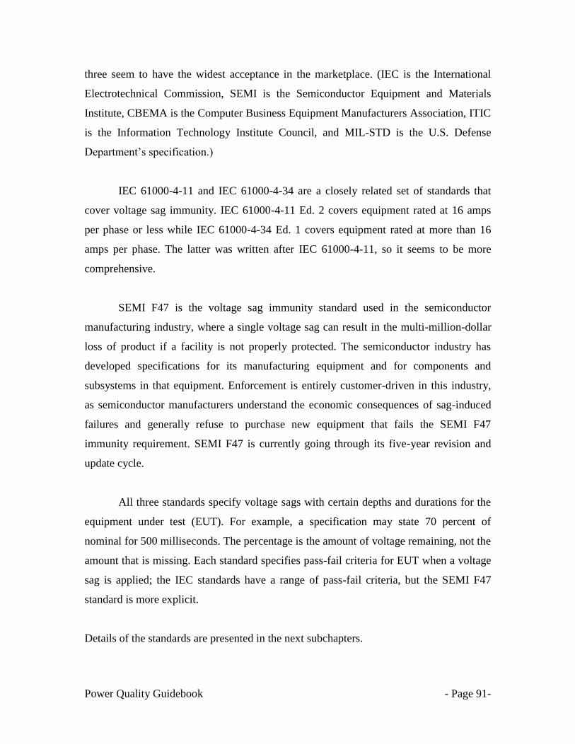
Power Quality Guidebook - Page 91-
three seem to have the widest acceptance in the marketplace. (IEC is the International
Electrotechnical Commission, SEMI is the Semiconductor Equipment and Materials
Institute, CBEMA is the Computer Business Equipment Manufacturers Association, ITIC
is the Information Technology Institute Council, and MIL-STD is the U.S. Defense
Department‘s specification.)
IEC 61000-4-11 and IEC 61000-4-34 are a closely related set of standards that
cover voltage sag immunity. IEC 61000-4-11 Ed. 2 covers equipment rated at 16 amps
per phase or less while IEC 61000-4-34 Ed. 1 covers equipment rated at more than 16
amps per phase. The latter was written after IEC 61000-4-11, so it seems to be more
comprehensive.
SEMI F47 is the voltage sag immunity standard used in the semiconductor
manufacturing industry, where a single voltage sag can result in the multi-million-dollar
loss of product if a facility is not properly protected. The semiconductor industry has
developed specifications for its manufacturing equipment and for components and
subsystems in that equipment. Enforcement is entirely customer-driven in this industry,
as semiconductor manufacturers understand the economic consequences of sag-induced
failures and generally refuse to purchase new equipment that fails the SEMI F47
immunity requirement. SEMI F47 is currently going through its five-year revision and
update cycle.
All three standards specify voltage sags with certain depths and durations for the
equipment under test (EUT). For example, a specification may state 70 percent of
nominal for 500 milliseconds. The percentage is the amount of voltage remaining, not the
amount that is missing. Each standard specifies pass-fail criteria for EUT when a voltage
sag is applied; the IEC standards have a range of pass-fail criteria, but the SEMI F47
standard is more explicit.
Details of the standards are presented in the next subchapters.
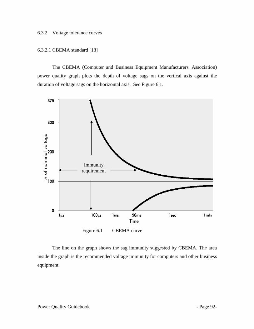
Power Quality Guidebook - Page 92-
6.3.2 Voltage tolerance curves
6.3.2.1 CBEMA standard [18]
The CBEMA (Computer and Business Equipment Manufacturers' Association)
power quality graph plots the depth of voltage sags on the vertical axis against the
duration of voltage sags on the horizontal axis. See Figure 6.1.
Figure 6.1 CBEMA curve
The line on the graph shows the sag immunity suggested by CBEMA. The area
inside the graph is the recommended voltage immunity for computers and other business
equipment.
Immunity
requirement

Power Quality Guidebook - Page 93-
6.3.2.2 ITIC standard [19]
ITIC Curve is a modified version of the CBEMA power acceptability curve, but
the concept remains the same. It was developed by a working group of the CBEMA,
which later changed its name to the Information Technology Industry Council (ITI). The
intent was to derive a curve that can better reflect the performance of typical single-
phase, 120 V, 60 Hz computers and their peripherals, and other information technology
items like fax machines, copiers and point-of-sales terminals.
The ITIC curve has been applied to general power quality evaluation, even though it was
primarily developed for 120 V computer equipment just like the CBEMA curve.
Figure 6.2 ITIC & CBEMA curve

Power Quality Guidebook - Page 94-
6.3.2.3 SEMI F47 standard [20]
A notable addition to the industrial and IT process power quality standards has
been the recent specification SEMI F47-0706. The requirements of the SEMI
specification were developed to satisfy the needs of the semiconductor industry. This
specification sets minimum voltage sag immunity requirements for equipment used in the
semiconductor industry. Immunity is specified in terms of voltage sag depth (in percent
of nominal voltage remaining during the sag) and voltage sag duration (in cycles or
seconds). This specification also sets procurement requirement, test methods, pass/fail
criteria, and test report requirements.
Figure 6.3 SEMI F47-0706 curve
Thus, the requirements developed in the SEMI specification are better suited to
the semiconductor industry. The SEMI (curve) staircase is specified for voltage dips with
a duration 0.05s – 1s. An arguable advantage of the SEMI curve as a benchmark for site
20 50 100 150 200 300 400 500 600 700 10,000 100,000
20
30
40
50
60
70
80
90
100
10
0
%
ms
% o
f n
om
ina
l vo
lta
ge
Duration of Voltage Sag (ms)
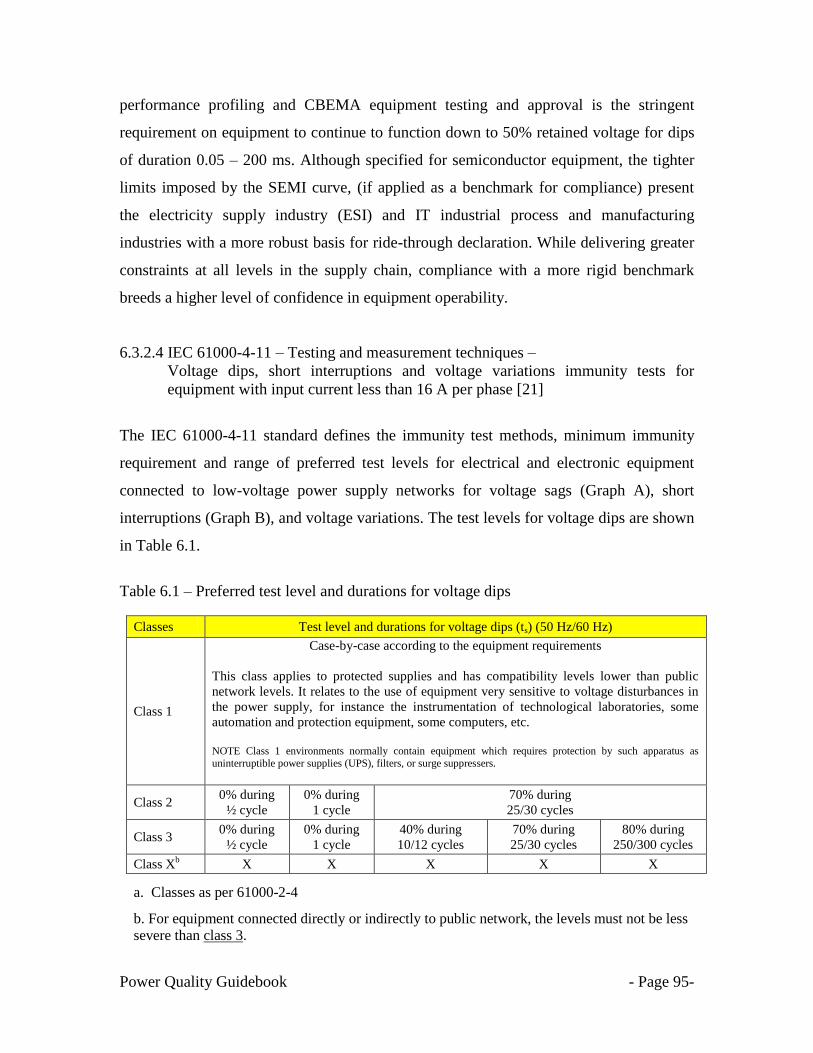
Power Quality Guidebook - Page 95-
performance profiling and CBEMA equipment testing and approval is the stringent
requirement on equipment to continue to function down to 50% retained voltage for dips
of duration 0.05 – 200 ms. Although specified for semiconductor equipment, the tighter
limits imposed by the SEMI curve, (if applied as a benchmark for compliance) present
the electricity supply industry (ESI) and IT industrial process and manufacturing
industries with a more robust basis for ride-through declaration. While delivering greater
constraints at all levels in the supply chain, compliance with a more rigid benchmark
breeds a higher level of confidence in equipment operability.
6.3.2.4 IEC 61000-4-11 – Testing and measurement techniques –
Voltage dips, short interruptions and voltage variations immunity tests for
equipment with input current less than 16 A per phase [21]
The IEC 61000-4-11 standard defines the immunity test methods, minimum immunity
requirement and range of preferred test levels for electrical and electronic equipment
connected to low-voltage power supply networks for voltage sags (Graph A), short
interruptions (Graph B), and voltage variations. The test levels for voltage dips are shown
in Table 6.1.
Table 6.1 – Preferred test level and durations for voltage dips
Classes Test level and durations for voltage dips (ts) (50 Hz/60 Hz)
Class 1
Case-by-case according to the equipment requirements
This class applies to protected supplies and has compatibility levels lower than public
network levels. It relates to the use of equipment very sensitive to voltage disturbances in
the power supply, for instance the instrumentation of technological laboratories, some
automation and protection equipment, some computers, etc.
NOTE Class 1 environments normally contain equipment which requires protection by such apparatus as
uninterruptible power supplies (UPS), filters, or surge suppressers.
Class 2 0% during
½ cycle
0% during
1 cycle
70% during
25/30 cycles
Class 3 0% during
½ cycle
0% during
1 cycle
40% during
10/12 cycles
70% during
25/30 cycles
80% during
250/300 cycles
Class Xb X X X X X
a. Classes as per 61000-2-4
b. For equipment connected directly or indirectly to public network, the levels must not be less
severe than class 3.

Power Quality Guidebook - Page 96-
c. Class Xb is a new voltage tolerance test to be developed in the future.
d. "25/30 cycles" means "25 cycles for 50 Hz test" and "30 cycles for 60 Hz test".
The IEC 61000-4-11 covers equipment installed in residential areas as well as industrial
machinery, specifically for voltage sags and short interruptions for equipment connected
to either 50 Hz or 60 Hz a.c networks, including 1-phase and 3-phase mains.
Figure 6.4 IEC 61000-4-11 (Class 3) curve
Graph A is the test level for voltage sag. Graph B is the test level for short interruption.
20 50 100 150 200 300 400 500 600 700 1000 2000 3000 4000 5000
20
30
40
50
60
70
80
90
100
Graph A
Graph B
10
0
%
ms
% o
f n
om
ina
l vo
lta
ge
Duration of Voltage Sag (ms)
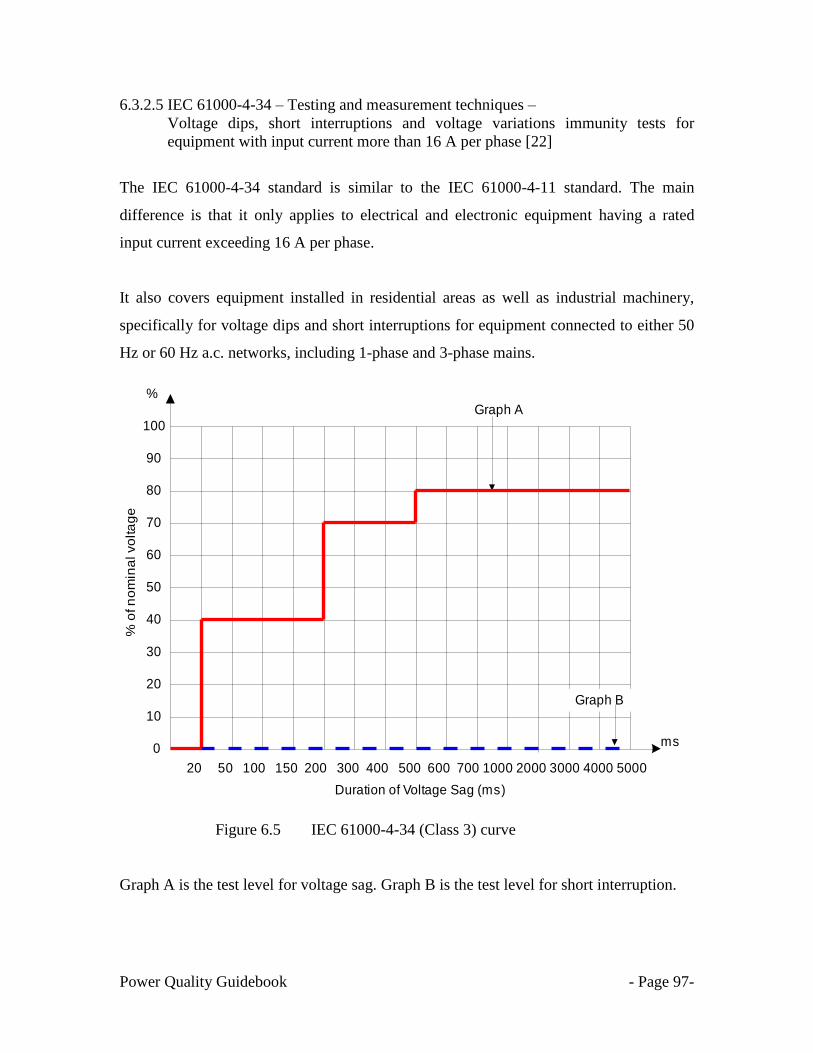
Power Quality Guidebook - Page 97-
6.3.2.5 IEC 61000-4-34 – Testing and measurement techniques –
Voltage dips, short interruptions and voltage variations immunity tests for
equipment with input current more than 16 A per phase [22]
The IEC 61000-4-34 standard is similar to the IEC 61000-4-11 standard. The main
difference is that it only applies to electrical and electronic equipment having a rated
input current exceeding 16 A per phase.
It also covers equipment installed in residential areas as well as industrial machinery,
specifically for voltage dips and short interruptions for equipment connected to either 50
Hz or 60 Hz a.c. networks, including 1-phase and 3-phase mains.
Figure 6.5 IEC 61000-4-34 (Class 3) curve
Graph A is the test level for voltage sag. Graph B is the test level for short interruption.
20 50 100 150 200 300 400 500 600 700 1000 2000 3000 4000 5000
20
30
40
50
60
70
80
90
100
Graph A
Graph B
10
0
%
ms
% o
f n
om
ina
l vo
lta
ge
Duration of Voltage Sag (ms)

Power Quality Guidebook - Page 98-
CHAPTER 7
CHARACTERIZING EQUIPMENT SENSITIVITY
7.1 INTRODUCTION
Voltage sags at equipment terminals are influenced by the transformer
connections between the fault location on the supply system and the equipment
connection point. The transformer connections will influence both the magnitude and the
phase relationship of the voltage sag experienced by the equipment.
These phenomena are random in nature and can be minimally characterized for
the purpose of laboratory simulation in terms of the deviation from the rated voltage, and
duration. Consequently, different types of tests are developed to simulate the effects of
abrupt voltage change.
7.2 Objective of equipment immunity testing
The objective of this section is to define the test method used to characterize the
susceptibility of automated processes and automated test equipment to voltage sags. In
this section, the scope covers: -
a. Characterizing the susceptibility of equipment to voltage sags by showing voltage sag
duration and magnitude performance data for the equipment.
b. Qualifying equipment to meet voltage sag ride-through specifications by comparing
the equipment voltage sag ride-through performance to industry/technical standards.
Sensitive machinery will be experiencing mal-operation every time a voltage sag event
occurs. This is due to the incapability of the equipment to ride through the voltage sag
event or in other words the immunity of the equipment is very low.

Power Quality Guidebook - Page 99-
The typical equipment sensitivity to voltage sag is shown in Table 7.1.
Table 7.1 Typical equipment sensitivity
Type of Equipment Remaining
voltage (%)
Duration (ms)
Motor starter 50 40
Variable speed motor with electronics 85 10
PLC I/O Device 50-90 8-20
Frequency inverter 82 1.5
Variable Speed Drive rectifier 50-80 2-3
Process controller 70 < 8
Computerized numerical controlled lathe 70 < 8
Direct Current drive controller 88 < 8
Personal Computer 50-70 60-160
Contactors 50-60 20-30
Electromagnetic disconnecting switch 50 10
Electromagnetic relays 50-60 15-40
Medical equipment 60 130
Servo drives 80 50
Laser marker 90 100
Figure 7.1
Programmable Logic
Control (PLC)

Power Quality Guidebook - Page 100-
Alternating current (ac) drive
Direct current (dc) drive
Servo Drive
Frequency Inverter
Figure 7.2 Examples of sensitive equipment in industrial plants

Power Quality Guidebook - Page 101-
7.3 Analyzing machinery immunity and sensitivity to voltage sag
7.3.1 Simple method to verify the equipment sensitivity to voltage sags
The first step towards a cost-effective solution is to understand the sensitivity of
the electronic equipment to momentary interruptions and voltage sags. Customers can
find this information by consulting the equipment manufacturer‘s specifications and
testing data. Another simple method to verify the equipment sensitivity is to use the
existing data for voltage sag recorded via existing power quality recorder installed nearest
to the plant and equipment. Most power utilities install online power quality monitoring
system (PQMS) at their substation to monitor power quality.
After the occurrence of a voltage sag event, TNB will share the data on voltage
sag received via short message system (SMS) with the affected prime customers. These
data are obtained from online PQMS which is located at the nearest substation to the
customers. The voltage sag data are recorded at the medium voltage level at the
substation at 11, 22 or 33 kV. As explained in sub chapter 4.5 (propagation of voltage
sags), the types of voltage sag will undergone transformation once it travels from the
power system to the step down transformer, to the lower voltage levels and to the
customer‘s loads.
SMS A
SMS B
Figure 7.3 Examples of SMS on voltage sags received from TNB.

Power Quality Guidebook - Page 102-
Examples of the SMS shared with customers are shown in Figure 7.3. The voltage sags
were recorded at the 11 kV (SMS A) and 33 kV (SMS B) voltage levels. Referring to
tables 4.3 & 4.4, the customers can estimate the type of the voltage sag experience at their
critical equipment.
From Table 4.3 Transformation of voltage sag type to lower voltage level (after Tx)
Connection Sag on primary side
Type A Type B Type C Type D Type E Type F Type G
YNyn A B C D E F G
Yy, Dd, Dz A D C D G F G
Yd, Dy, Yz A C D C F G F
From Table 4.4 Transformation of voltage sag type to lower voltage level (Load side)
Fault Type Load Connection
Star Delta
Three phase A A
Two phase to ground E F
Phase to phase C D
Single phase B C
Below are the steps to follows:
Part 1 Verification of voltage sag event
1.1 Verify the symptoms of voltage sags i.e. light blinks and critical equipment trips.
1.2. Verify which relay, control systems and equipment were affected by the voltage
sags.
1.3. Verify the available power quality data (if available) from power quality recorder
in the plant,
1.4. Please confirm the source of the voltage sag event either from outside the plant or
due to internal equipment fault.
1.5. Verify with TNB via special WhatsApp group or contact directly to the TNB
engineers
If data are available, TNB will share the SMS on voltage sag (Figure 7.3)

Power Quality Guidebook - Page 103-
If the cause of the voltage sag was due to an event that originated from outside the plant,
please do the following:-
1.6 Record the date and time of the voltage sag disturbance
1.7 If the system fault has been isolated, immediately commence the process to restart
the affected production.
1.8 Request an official report from TNB.
If the cause of the voltage sag was not confirmed due to an event that originated outside
the plant, please do the following:-
1.9 Record the date and time of the voltage sag disturbance
2.0 Please confirm with the nearby customers on any possible equipment flashover.
2.1 If the source of the event was not confirmed due to external causes, please
perform an internal investigation to verify possible internal equipment failure.
Part 2 Identification of weak links and immunity level
From the information obtained from 1.1 to 2.1, please summarize all the affected control
circuit and equipment together with the available power quality data,
If the data are sufficient, the sensitivity of the control circuit and critical equipment can
be estimated from the available power quality data. Examples of equipment sensitivity
are shown in Table 7.2.
Table 7.2 Typical equipment sensitivity based on voltage sag data
Equipment
affected by
voltage sags
Minimum values of voltage sag
Voltage (%) Duration (ms)
PLC 90 50
VSD 85 80
Contactors 60 80
Relays 80 50
Based on the information in Table 7.2, next, refer to subchapter 7.5 for procedure to
harden the sensitive process & selection of power conditions to protect the sensitive
equipment against voltage sag.

Power Quality Guidebook - Page 104-
7.3.2 Testing method to verify the equipment sensitivity to voltage sags
Another way to identify the sensitivity of equipment to voltage sags is by using a
measuring device called a voltage sag generator, which can generate controlled voltage
sags and records the responses of the equipment. In the market today, there are a few
types of programmable sag generators available. Examples are the programmable ac
source [23], the industrial power corruptor (IPC) [24], Voltage Dip & Swell Simulator
VDS 2002, Voltage DIP Simulator VDS-220B & Voltage dip, interrupt and variation
simulator PFS2216.
Figure 7.4 Programmable AC source
Figure 7.5 Industrial Power Corruptor (IPC)
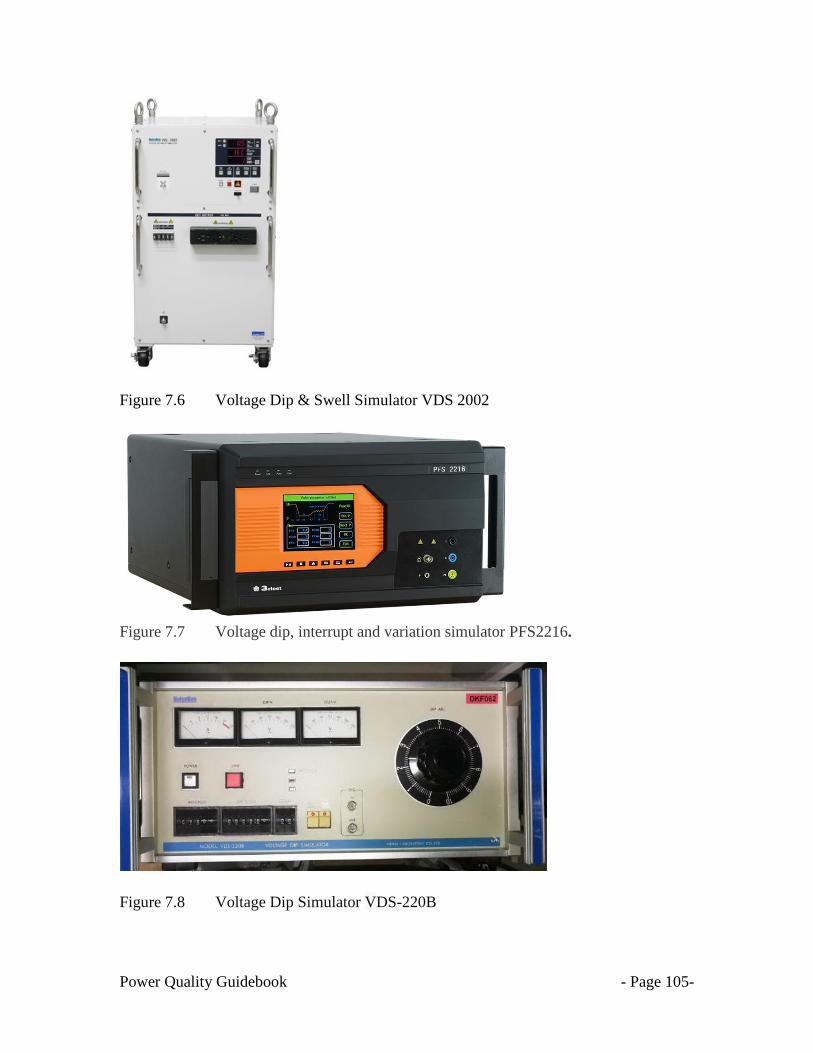
Power Quality Guidebook - Page 105-
Figure 7.6 Voltage Dip & Swell Simulator VDS 2002
Figure 7.7 Voltage dip, interrupt and variation simulator PFS2216.
Figure 7.8 Voltage Dip Simulator VDS-220B
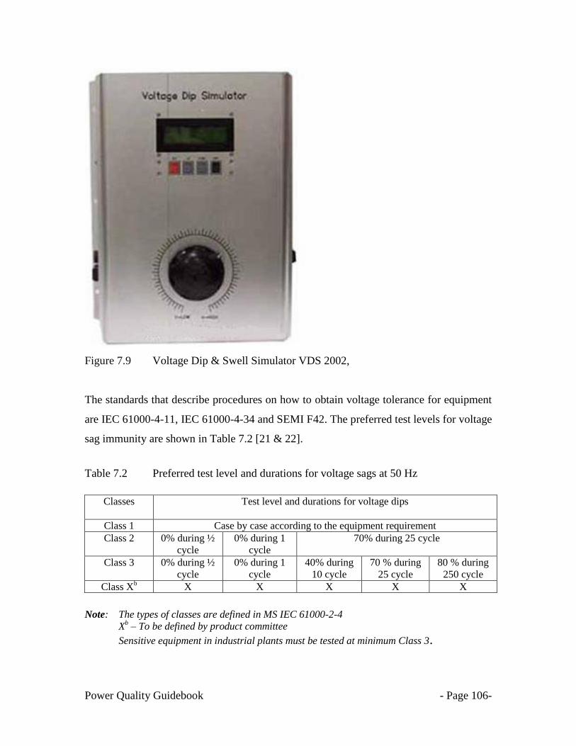
Power Quality Guidebook - Page 106-
Figure 7.9 Voltage Dip & Swell Simulator VDS 2002,
The standards that describe procedures on how to obtain voltage tolerance for equipment
are IEC 61000-4-11, IEC 61000-4-34 and SEMI F42. The preferred test levels for voltage
sag immunity are shown in Table 7.2 [21 & 22].
Table 7.2 Preferred test level and durations for voltage sags at 50 Hz
Classes Test level and durations for voltage dips
Class 1 Case by case according to the equipment requirement
Class 2 0% during ½
cycle
0% during 1
cycle
70% during 25 cycle
Class 3 0% during ½
cycle
0% during 1
cycle
40% during
10 cycle
70 % during
25 cycle
80 % during
250 cycle
Class Xb X X X X X
Note: The types of classes are defined in MS IEC 61000-2-4
Xb – To be defined by product committee
Sensitive equipment in industrial plants must be tested at minimum Class 3.

Power Quality Guidebook - Page 107-
7.3.1 Test instrumentation for voltage sag generator
The following features are common to the generator for voltage sags, short interruptions
and voltage variations.
Table 7.3 Characteristics and performance of the sag generator [23]
Output voltage at no load
As required in Table 7.2. 5% of residual voltage values
Voltage at the output of
generator during equipment test
As required in Table 7.2, ± 10% of residual voltage value,
measured as r.m.s. value refreshed each ½ cycle per IEC
61000-4-30
Output current capability
Less than 16 A r.m.s (MS IEC 61000-4-11) or more than 16
A r.m.s (IEC 61000-4-34) per phase at rated voltage.
Voltage rise (and fall) time tr
(and tf), during abrupt change,
generator loaded with resistive
load
Between 1 μs and 5 μs
Phase angle at which the
voltage dip begins and ends
0° to 360° with a maximum resolution of 5°
Phase relationship of voltage
dips and interruptions
with the power frequency
Less than ± 10 °
Zero crossing control of the
generators
± 10°
The test setup should consist of the following equipment as shown in Figure 7.10.
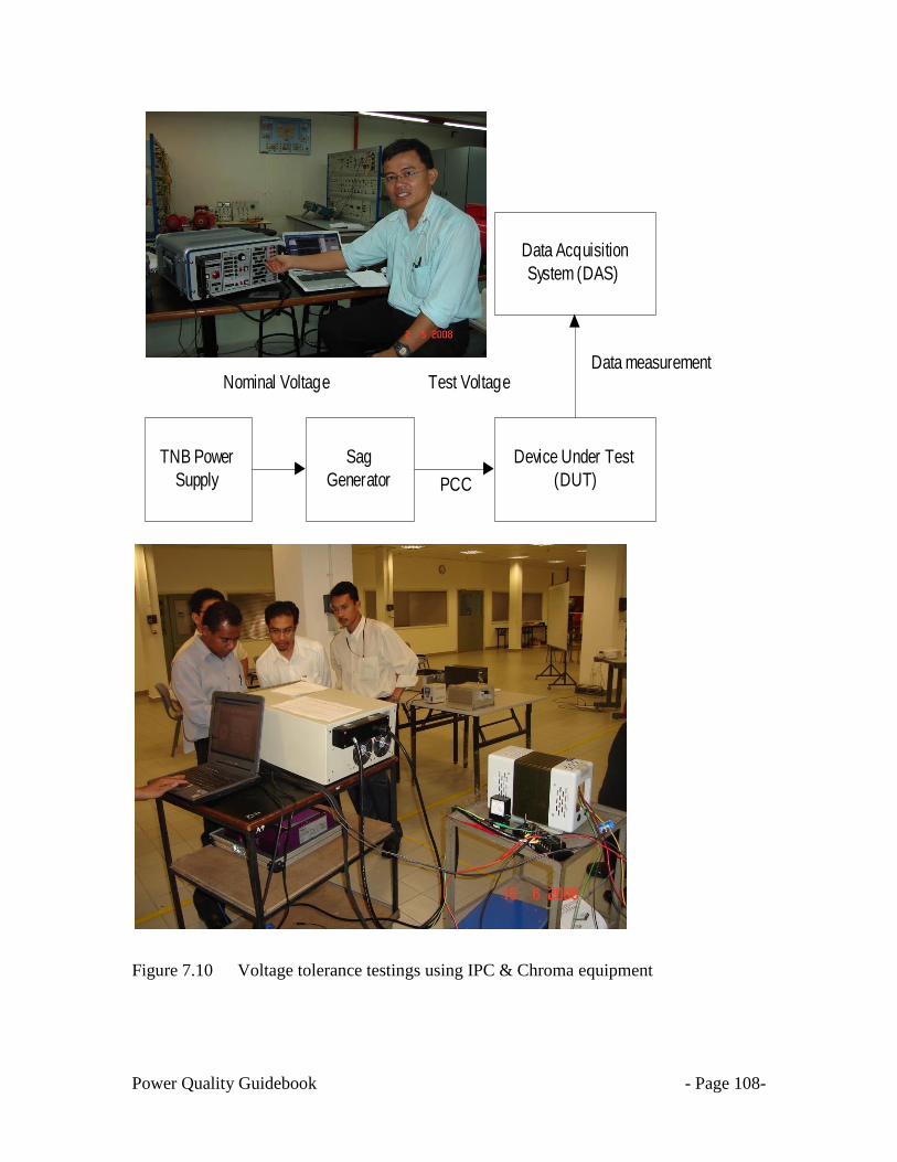
Power Quality Guidebook - Page 108-
Figure 7.10 Voltage tolerance testings using IPC & Chroma equipment
TNB Power
Supply
Sag
Generator
Device Under Test
(DUT)
Data Acquisition
System (DAS)
Nominal Voltage Test Voltage
PCC
Data measurement

Power Quality Guidebook - Page 109-
7.4 Evaluation of test results for voltage sag testing
The test results shall be classified in terms of the loss of function or degradation of
performance of the equipment under test, relative to a performance level defined by its
manufacturer or the requestor of the test, or agreed between the manufacturer and the
purchaser of the product.
The recommended classification is as follows:-
a) normal performance within limits specified by the manufacturer, requestor or
purchaser;
b) temporary loss of function or degradation of performance which ceases after the
disturbance ceases, and from which the equipment under test recovers its normal
performance, without operator intervention;
c) temporary loss of function or degradation of performance, the correction of
which requires operator intervention;
d) loss of function or degradation of performance, which is not recoverable, owing
to damage to hardware or software, or loss of data.
The manufacturer's specification may define the effects on the DUT, which may be
considered insignificant, and therefore acceptable. This classification may be used as a
guide in formulating performance criteria, product and product-family standards, or as a
framework for the agreement on performance criteria between the manufacturer and the
purchaser, for example in instances where no suitable generic, product or product-family
standard exists.

Power Quality Guidebook - Page 110-
7.5 Improving equipment immunity to voltage sag
After the voltage sensitivity of the equipment is known, analysis can be done to
identify measures to improve its immunity to voltage sag. With regard to voltage sags
that are moderate in depth and duration, some equipment can have a certain level of
inherent immunity, for example by virtue of its inertia or energy storage capacity.
Alternatively, it may be possible to make design adjustments or use of additional support
equipment i.e. power conditioner, so that this internal property is manifest.
Based on the information obtained from both methods (simple method and test
method), please refer to chapters 8 & 9 for common hardening process & selection of
power conditioners to protect the sensitive equipment against voltage sag.
However, for short interruptions, immunity is not, in its strict sense, a feasible
concept. The essential character of the event is that it involves the complete cessation or
severe diminution of the energy supply for a brief interval. No electrical device can
continue to operate as intended in the absence of its energy supply. Therefore, such
immunity as can be provided from these disturbances tends to be extrinsic - it is a matter
of either providing for:
fast restoration of energy from an alternative source or,
arranging for the equipment and its associated process to adapt in an intended manner
to the brief interruption or diminution of power.

Power Quality Guidebook - Page 111-
7.6 Evaluating the Economics [25]
Deciding on the best alternative for improving voltage sag ride-through performance at a
customer‘s facility is a problem that comes down to simple economics. We need to
understand the sensitivity of the equipment and how much it costs every time the
equipment is affected.
Then we need information from the electric utility that estimates how many voltage sags
to expect on your system per year. With this information in hand we can then determine
the costs associated with voltage sags. The optimum solution will minimize the combined
costs of the ride-through solution and the resulting losses from the events not solved by
the specific solution — the cost of the solution plus the cost of the disturbances.
The solution costs are lower as we focus on the particular equipment and controls that are
sensitive. However, this approach may have additional costs associated with
characterizing the sensitivity of the process components and installation. Efforts to
understand the sensitivity of all parts of your process are usually very worthwhile in
coming up with the best solution.
7.7 Improving Equipment Ride-through Characteristics
Ultimately, better equipment design is the best long-term solution for voltage sag
problems. If manufacturers offered options for improved ride-through, it might be more
economical to purchase these options than to install external devices for protection.
Power Quality Guidebook - Page 112-
CHAPTER 8
SOLUTIONS TO VOLTAGE SAGS
8.1 INTRODUCTION
In the blink of an eye, a voltage sag event can bring production and facility
systems in a company to a halt. To the human eye, voltage sags can cause the lights to
dim. To automation equipment, sags can mean shutdown of equipment, loss of data
and unexplained resets. Over time, voltage sags can stress components, resulting in
premature wear and failure.
For processes that rely on high speed, any interruption can lead to significant
production shortages. For processes that take hours to create one part, or a single batch
of parts, process interruptions have a significant impact on company profits.
Shutdowns result in scrapped work, production shortages, reduced service levels to
customers and less income for the company.
Many manufacturing and process industries need to focus on ensuring full
protection against voltage sag to maintain maximum competitiveness, productivity and
quality. The Semiconductor Equipment and Materials Institute have gone so far as to
establish a minimum standard with regard to sag immunity performance for
semiconductor tools and equipment. SEMI F47 introduced a well thought out voltage-
to-time curve that most equipment will be exposed to during normal operation. In
addition, a specific method of test and reporting had been developed.
.
The IEC 61000-4-11 and IEC 61000-4-34 also promotes minimum voltage sag
immunity requirement. These standards also specify the requirement for the sag
generator and testing methodology.
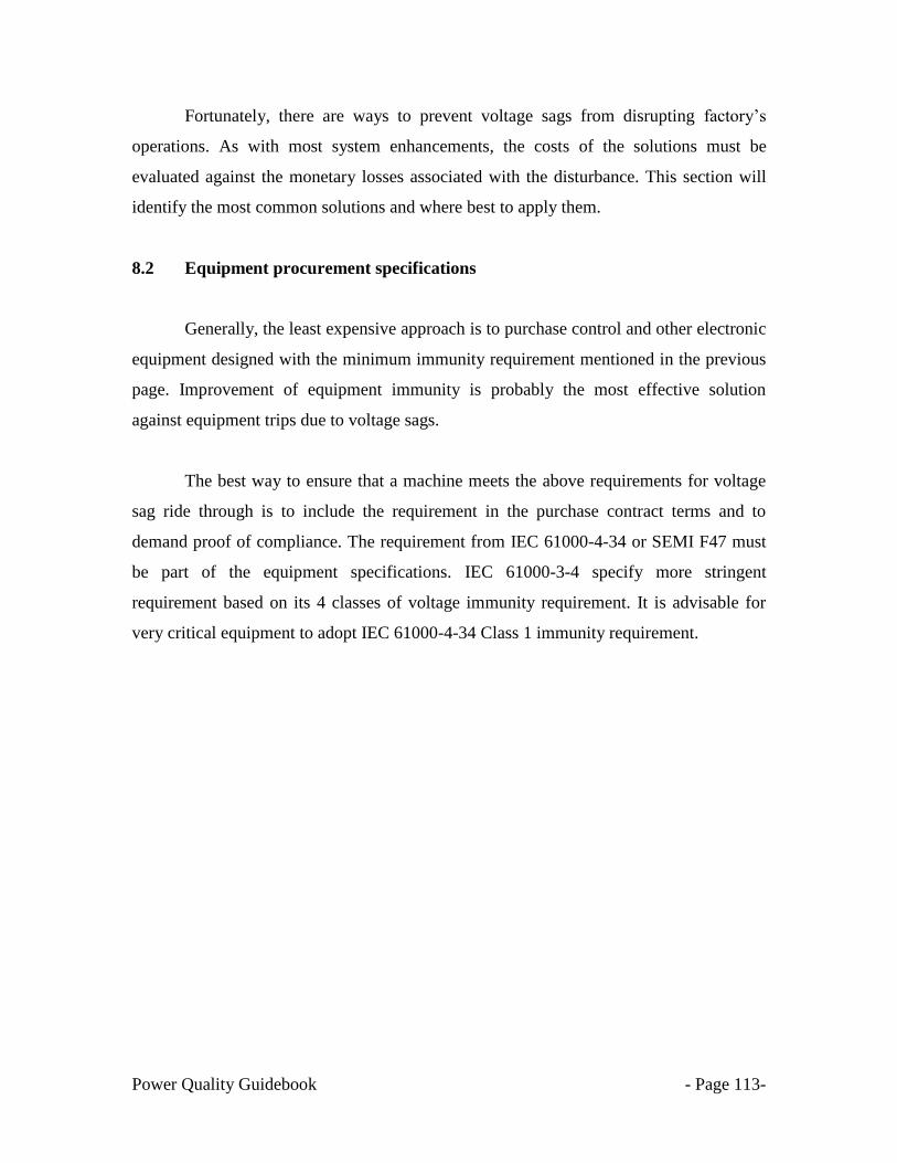
Power Quality Guidebook - Page 113-
Fortunately, there are ways to prevent voltage sags from disrupting factory‘s
operations. As with most system enhancements, the costs of the solutions must be
evaluated against the monetary losses associated with the disturbance. This section will
identify the most common solutions and where best to apply them.
8.2 Equipment procurement specifications
Generally, the least expensive approach is to purchase control and other electronic
equipment designed with the minimum immunity requirement mentioned in the previous
page. Improvement of equipment immunity is probably the most effective solution
against equipment trips due to voltage sags.
The best way to ensure that a machine meets the above requirements for voltage
sag ride through is to include the requirement in the purchase contract terms and to
demand proof of compliance. The requirement from IEC 61000-4-34 or SEMI F47 must
be part of the equipment specifications. IEC 61000-3-4 specify more stringent
requirement based on its 4 classes of voltage immunity requirement. It is advisable for
very critical equipment to adopt IEC 61000-4-34 Class 1 immunity requirement.
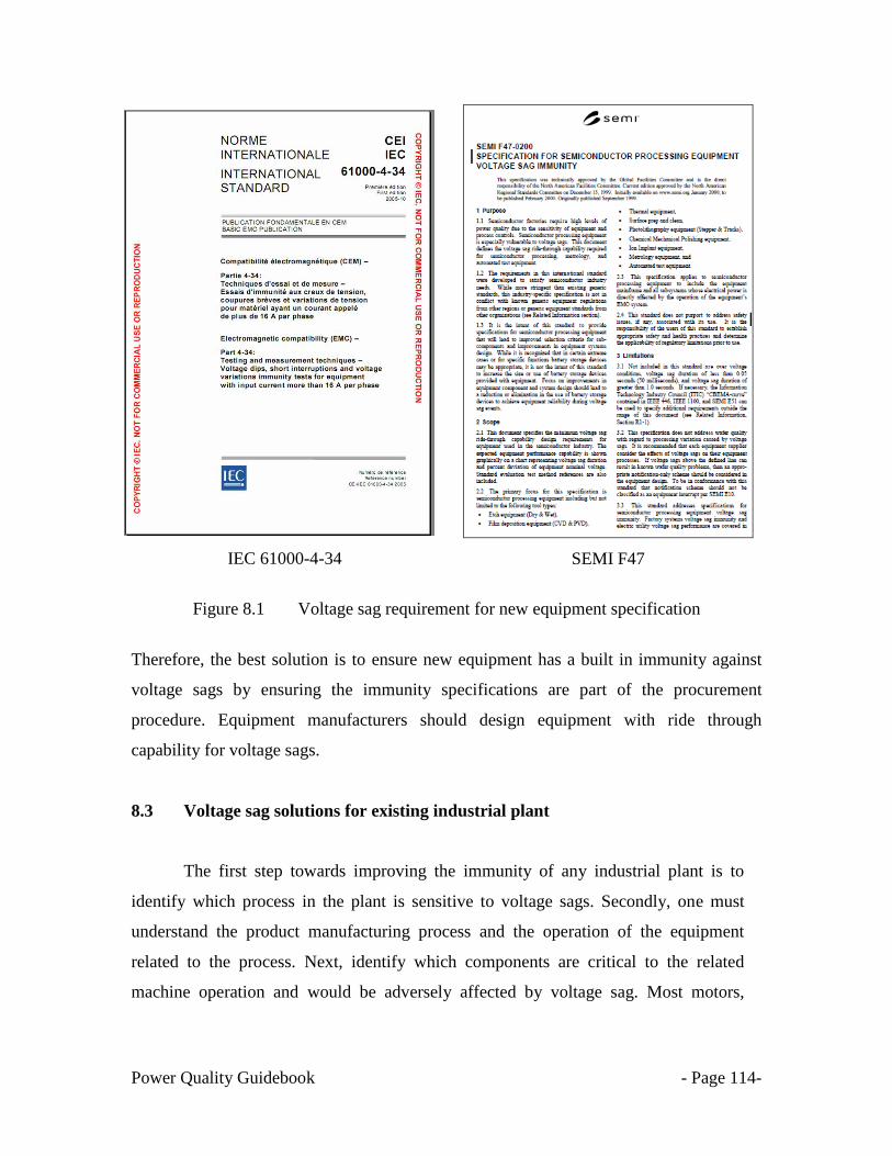
Power Quality Guidebook - Page 114-
IEC 61000-4-34
SEMI F47
Figure 8.1 Voltage sag requirement for new equipment specification
Therefore, the best solution is to ensure new equipment has a built in immunity against
voltage sags by ensuring the immunity specifications are part of the procurement
procedure. Equipment manufacturers should design equipment with ride through
capability for voltage sags.
8.3 Voltage sag solutions for existing industrial plant
The first step towards improving the immunity of any industrial plant is to
identify which process in the plant is sensitive to voltage sags. Secondly, one must
understand the product manufacturing process and the operation of the equipment
related to the process. Next, identify which components are critical to the related
machine operation and would be adversely affected by voltage sag. Most motors,

Power Quality Guidebook - Page 115-
lighting and indicators can tolerate short-duration sag with negligible detriment to
production.
Normally, the most critical and normally sag-sensitive component is normally
the ac-dc power supply used to power all dc control and programmable logic circuits.
A majority of power supply modules currently available on the market average 10 to
20 ms of hold-up time at full load. These devices will not meet the sag immunity
performance needed to work during common sag events without special considerations
taken by the system designer.
The immediate action plan that one can consider is to protect or harden the
control and logic circuits from voltage sags. There are a few methods available to
protect these circuitries. By implementing these methods, the control circuitries will be
protected against voltage sags but not the primary equipment they are controlling.
For chillers, compressors or other motor loads, by protecting their control
circuitries only, the motors will be experiencing a slight reduction in speed during a
voltage sag event. The plant engineer must understand the impact of the motors
slowing down. The production process in the plant must not be affected by the
reduction of the motor speed. The other thing to consider is the impact of the voltage
sags to the primary equipment, for example motors, etc. The protected control circuitry
will ensure the primary equipment is still connected and exposed to the short duration
voltage sags. Will there be any side effect on the motor etc?
Therefore, to ensure a successful voltage sag solution for existing industrial
plants, a detailed discussion must be done with the plant engineer and equipment
supplier before implementing the voltage sag immunity solutions.

Power Quality Guidebook - Page 116-
8.3.1 Hardening requirement for control and logic circuits
One simple option is to use a universal input power supply (85-264 Volt) and power
from the higher line voltage (208/240 Volt). This, of course, only meets the needed
level of performance when powered from the higher line voltage.
8.3.1.1 SEMI F47 compliant power source
Another simple method is to use a SEMI F47 compliance power supply to power the
control circuit.
Figure 8.2 Example of a SEMI F47 compliance power supply
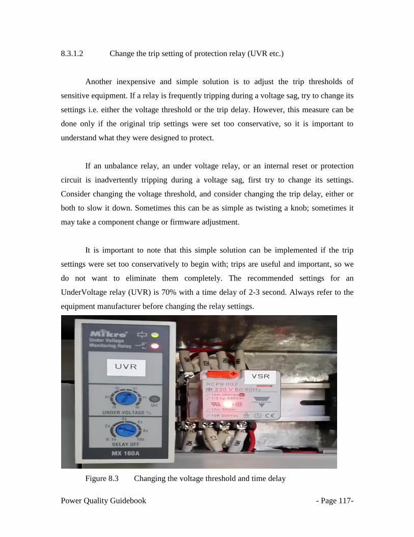
Power Quality Guidebook - Page 117-
8.3.1.2 Change the trip setting of protection relay (UVR etc.)
Another inexpensive and simple solution is to adjust the trip thresholds of
sensitive equipment. If a relay is frequently tripping during a voltage sag, try to change its
settings i.e. either the voltage threshold or the trip delay. However, this measure can be
done only if the original trip settings were set too conservative, so it is important to
understand what they were designed to protect.
If an unbalance relay, an under voltage relay, or an internal reset or protection
circuit is inadvertently tripping during a voltage sag, first try to change its settings.
Consider changing the voltage threshold, and consider changing the trip delay, either or
both to slow it down. Sometimes this can be as simple as twisting a knob; sometimes it
may take a component change or firmware adjustment.
It is important to note that this simple solution can be implemented if the trip
settings were set too conservatively to begin with; trips are useful and important, so we
do not want to eliminate them completely. The recommended settings for an
UnderVoltage relay (UVR) is 70% with a time delay of 2-3 second. Always refer to the
equipment manufacturer before changing the relay settings.
Figure 8.3 Changing the voltage threshold and time delay

Power Quality Guidebook - Page 118-
8.3.1.3 Installing a coil hold-in device [26].
Another option is to install a coil hold-in device. These devices are designed to
mitigate the effects of voltage sags on individual relays and contactors. Coil hold-in
devices are installed between the relay or contactor coil connection terminals and the
incoming alternating current (ac) control line. They allow a relay or contactor to remain
engaged until the voltage drops to about 25 % of nominal, significantly improving its
voltage sag tolerance without interfering with emergency shutoff functions. The best
application for this type of device is to support relays and contactors in an emergency off
(EMO) circuit, master control relay, or motor control circuit.
Figure 8.4 A coil hold-in device
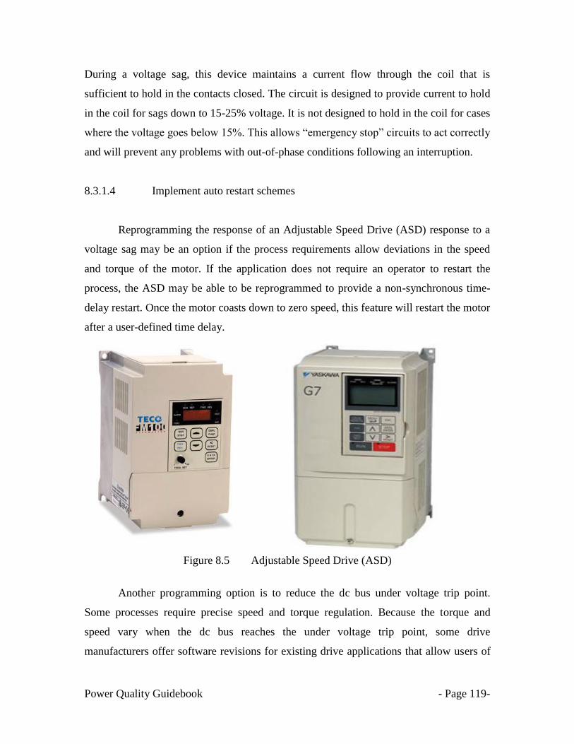
Power Quality Guidebook - Page 119-
During a voltage sag, this device maintains a current flow through the coil that is
sufficient to hold in the contacts closed. The circuit is designed to provide current to hold
in the coil for sags down to 15-25% voltage. It is not designed to hold in the coil for cases
where the voltage goes below 15%. This allows ―emergency stop‖ circuits to act correctly
and will prevent any problems with out-of-phase conditions following an interruption.
8.3.1.4 Implement auto restart schemes
Reprogramming the response of an Adjustable Speed Drive (ASD) response to a
voltage sag may be an option if the process requirements allow deviations in the speed
and torque of the motor. If the application does not require an operator to restart the
process, the ASD may be able to be reprogrammed to provide a non-synchronous time-
delay restart. Once the motor coasts down to zero speed, this feature will restart the motor
after a user-defined time delay.
Figure 8.5 Adjustable Speed Drive (ASD)
Another programming option is to reduce the dc bus under voltage trip point.
Some processes require precise speed and torque regulation. Because the torque and
speed vary when the dc bus reaches the under voltage trip point, some drive
manufacturers offer software revisions for existing drive applications that allow users of

Power Quality Guidebook - Page 120-
ac drives to lower the dc bus under voltage trip point. By lowering the trip point, drives
and processes can ride through longer and deeper voltage sags without interrupting
production.
Often, the software revisions are not part of the standard drive control software
and must be requested from the manufacturer. The drawback to this approach is that
rectifiers and fuses may be damaged due to high inrush current and over current
conditions. The current increases as the dc bus under voltage trip point decreases. These
conditions should be considered when lowering the under voltage trip point.
8.3.1.5 To maintain the DC link voltage for ASD.
Figure 8.6 Single line diagram for a typical Adjustable Speed Drive (ASD)
Note: IGBT- An insulated-gate bipolar transistor (IGBT) is a three-terminal power
semiconductor device primarily used as an electronic switch which, as it
was developed, came to combine high efficiency and fast switching.

Power Quality Guidebook - Page 121-
There are different ways to improve ride-through for ASD. In the literature mainly three
ideas for voltage sag ride-through are mentioned. The first two are aimed at maintaining
the DC-link voltage.
The ideas for voltage sag ride through are as follows:
• Keep up the DC-link voltage electronically.
This can be made by making the energy storage larger, i.e., a larger DC-link capacitor or
relying on batteries (so-called uninterruptible power supplies, UPS).
These solutions tend to become bulky and expensive if the voltage should remain at the
nominal level for longer periods.
Another solution is to use an active rectifier or a chopper
• Keep up the DC-link voltage with load inertia,
If the plant is equipped with large rotating masses (e.g., paper mills) these energy
storages can be used as generators to keep up the DC-link voltage during the sag.
This works even for a sag of longer duration. It is also a good solution to a controlled
shutdown (at an interruption), as the DC-link voltage can be held at the highest possible
level for the time it takes to make this shutdown.
A requirement is that the process uses several motor drives that are fed by a common DC
link. If the process does not have a large rotating mass, there is the possibility to use an
extra flywheel. (The drawback is that the system becomes slower due to the extra inertia.)
• Let the DC-link voltage vary and control the drive properly.
Naturally, the above two solutions are costly. If we can accept that the DC-link voltage
varies (and instead use better control), a less expensive solution is obtained.

Power Quality Guidebook - Page 122-
8.3.1.6 Change the settings for unbalance relay
On three-phase systems, voltage sags are often asymmetrical (they affect one or two
phases more than the remaining phases). Three-phase motors and transformers can be
damaged by sustained voltage unbalance; it can cause the transformer or motor to
overheat. So it makes sense to put in an unbalance relay, which is a device that shuts
down the system if the voltage unbalance exceeds some threshold, typically a few
percent.
To minimize the impact of voltage sag, it is recommended to set the unbalance relay at
20-50% unbalance with a delay time of 2 seconds.
Figure 8.7 Unbalance relay
.
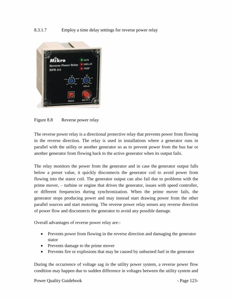
Power Quality Guidebook - Page 123-
8.3.1.7 Employ a time delay settings for reverse power relay
Figure 8.8 Reverse power relay
The reverse power relay is a directional protective relay that prevents power from flowing
in the reverse direction. The relay is used in installations where a generator runs in
parallel with the utility or another generator so as to prevent power from the bus bar or
another generator from flowing back to the active generator when its output fails.
The relay monitors the power from the generator and in case the generator output falls
below a preset value, it quickly disconnects the generator coil to avoid power from
flowing into the stator coil. The generator output can also fail due to problems with the
prime mover, – turbine or engine that drives the generator, issues with speed controller,
or different frequencies during synchronization. When the prime mover fails, the
generator stops producing power and may instead start drawing power from the other
parallel sources and start motoring. The reverse power relay senses any reverse direction
of power flow and disconnects the generator to avoid any possible damage.
Overall advantages of reverse power relay are:-
Prevents power from flowing in the reverse direction and damaging the generator
stator
Prevents damage to the prime mover
Prevents fire or explosions that may be caused by unburned fuel in the generator
During the occurrence of voltage sag in the utility power system, a reverse power flow
condition may happen due to sudden difference in voltages between the utility system and

Power Quality Guidebook - Page 124-
the generator. The reverse power relay senses any reverse direction of power flow and
disconnects the main circuit breaker to avoid any incident the generator feeding into the
system faults. To minimize the tripping of the main circuit breaker due to reverse power
flow, it is recommended to activate the time delay to 3 second.
8.3.1.8 Overall actions for hardening the control circuit & protection relays
Tip No Descriptions
1 Use a universal & compliance power supply (85-264 Volt)
2 Use DC supply (if applicable)
3 Wire load devices in a phase-to-phase configuration
4 Identify & improve sensitive ice cube relays
5 Do not use phase monitoring relays or under voltage
relays (UVR) in the interlock circuit, VCB etc.
6 Install auto restart schemes (if applicable)
7 Employ Time Delay tripping for Motors, Contactors, UVR etc
(Voltage 70%, t= 3 seconds)
8 To study on maintaining DC link voltage for VFD, ASD etc.
9 Employ delay tripping for unbalance relay (20-50 %, t = 2
second)
10 Employ delay tripping for reverse power relay (t = 3 second)
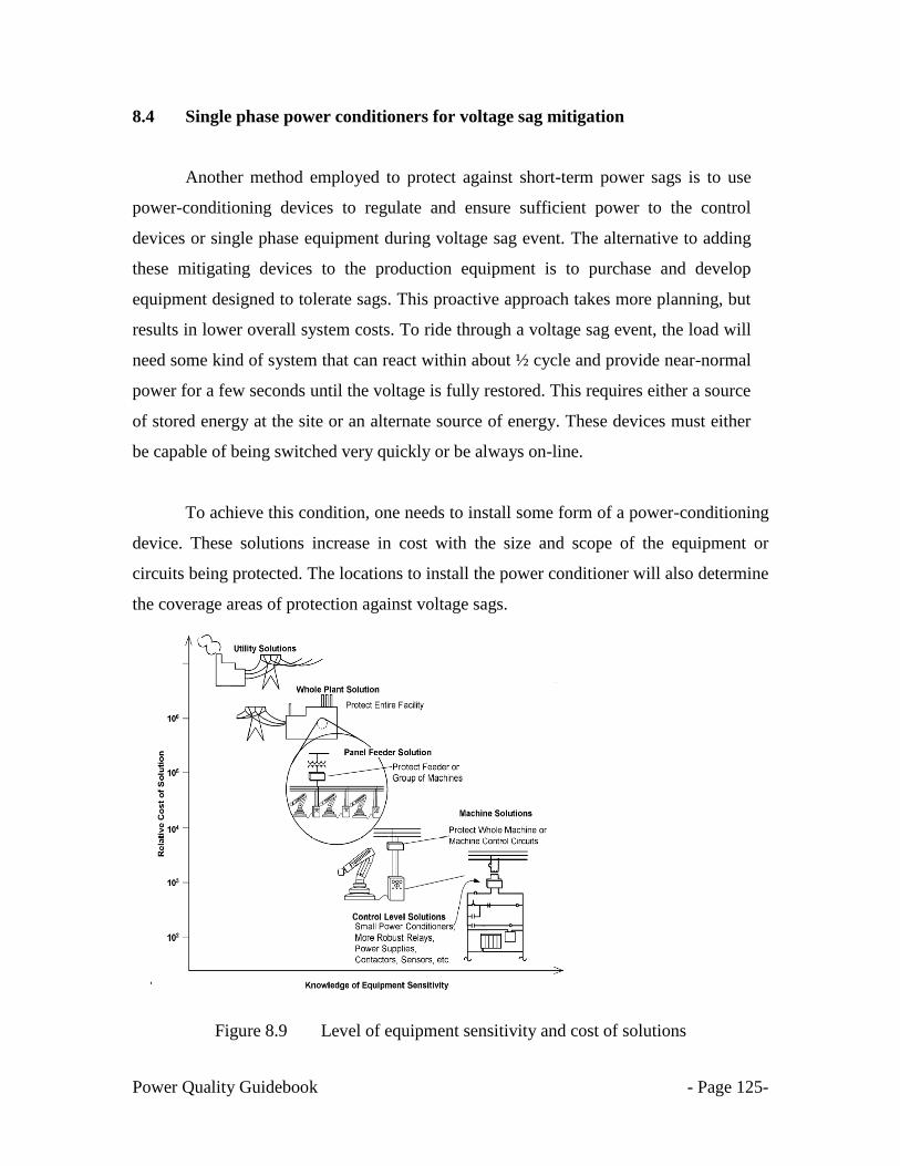
Power Quality Guidebook - Page 125-
8.4 Single phase power conditioners for voltage sag mitigation
Another method employed to protect against short-term power sags is to use
power-conditioning devices to regulate and ensure sufficient power to the control
devices or single phase equipment during voltage sag event. The alternative to adding
these mitigating devices to the production equipment is to purchase and develop
equipment designed to tolerate sags. This proactive approach takes more planning, but
results in lower overall system costs. To ride through a voltage sag event, the load will
need some kind of system that can react within about ½ cycle and provide near-normal
power for a few seconds until the voltage is fully restored. This requires either a source
of stored energy at the site or an alternate source of energy. These devices must either
be capable of being switched very quickly or be always on-line.
To achieve this condition, one needs to install some form of a power-conditioning
device. These solutions increase in cost with the size and scope of the equipment or
circuits being protected. The locations to install the power conditioner will also determine
the coverage areas of protection against voltage sags.
.
Figure 8.9 Level of equipment sensitivity and cost of solutions

Power Quality Guidebook - Page 126-
8.4.1 Sizing procedure for single-phase power conditioners
The power conditioners must be installed at the control system or at the control
transformer for the control system. Please refer to subchapter 4.8 for sample diagrams
for control circuits. To ensure correct sizing of the power conditioner, please take the
current & voltage values at the control transformer using a current clamp meter and
voltage indicator. Select the next highest rating (kVA) for the power conditioner.
Examples of the sizing of the power conditioners are shown in figures 8.10 & 8.11.
Once the size of the power conditioner is known, please choose the best power
conditioner to protect the control circuit from voltage sags. Please refer to IEC standards
in subchapters 6.3.2.4 & 6.3.2.5, to determine the immunity class requirement (C1, C2 or
C3).
Note. Please ensure there is no undervoltage relay (UVR) at the control circuit.
Figure 8.10 Example on sizing of single phase power conditioner 110 Volt

Power Quality Guidebook - Page 127-
Note. Please ensure there is no undervoltage relay (UVR) at the control circuit.
Figure 8.11 Example on sizing of single phase power conditioner 230 Volt
8.4.1.1 Uninterruptible Power Supply (UPS)
Installing an uninterruptible power supply (UPS), on a computer, programmable
logic control (PLC) or controls to switch to battery during a voltage sag or an interruption
will minimize process interruption. The down side to this approach is the battery. As an
example, lead acid batteries have the following disadvantages: a) generates hydrogen gas,
must be ventilated, b) battery lead is a hazardous waste, and c) battery life is limited and
decreases rapidly when cycled often.

Power Quality Guidebook - Page 128-
An advantage is that the UPS will ride through not only sags, but also momentary
and extended interruptions up to the limit of the battery capacity, maybe 5 to 10 minutes.
Note: Please verify the output voltage from the UPS is always +/-5 % from the nominal
voltage when exposed to voltage sag or momentary interruptions.
Figure 8.12 A Single Phase Uninterruptible Power Supply (UPS)
8.4.1.2 Constant Voltage Transformer (CVT)
Most voltage-sag solutions can be handled by ferroresonant transformers. These
power conditioners are also known as constant-voltage transformers (CVTs). CVTs are
ideally suited for constant, low-power loads. Unlike conventional transformers, the CVT
allows the core to become saturated with magnetic flux, which maintains a relatively
constant output voltage during input voltage variations such as under voltages, over
voltages, and harmonic distortion.

Power Quality Guidebook - Page 129-
Installing a ferroresonant (constant voltage transformer-CVT) transformer on a
computer, programmable logic control (PLC) or controls will provide sag ride through
capability. They also provide filtering of transients. CVT will not ride through a
momentary or sustained interruption. They have no moving parts, no battery and are very
reliable. Another consideration when sizing a CVT is the load characteristic. A CVT must
be sized for the maximum load.
Figure 8.13 Constant Voltage Transformer
When the transformer is overloaded, the voltage will decrease and collapse to zero
at approximately 150% of loading. Therefore, if the load profile includes an inrush
current or a starting motor, the transformer must be sized for this transient load, not the
steady-state load. CVTs provide voltage sag ride-through of 25 % for 1 second and also
filter spikes, but they are not able to protect against interruptions, either momentary or
sustained. CVTs are often used for relatively constant, low-power loads, and have the
advantage of lower operating and maintenance costs than UPSs, because CVTs do not
require batteries.
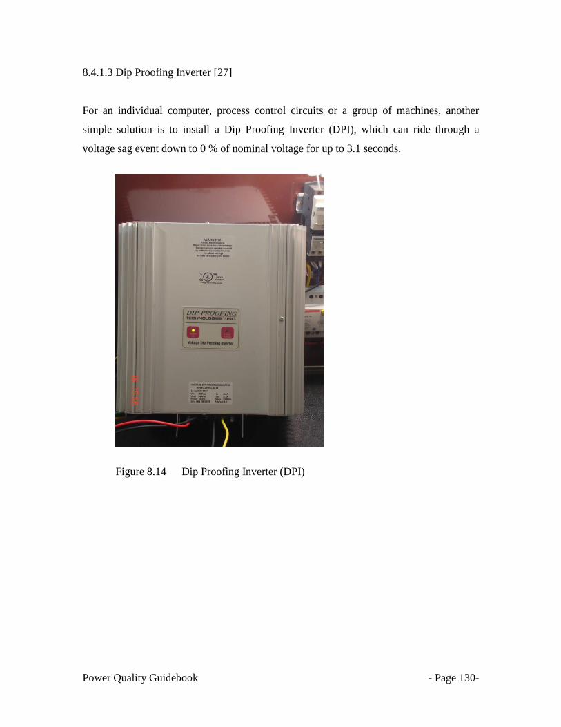
Power Quality Guidebook - Page 130-
8.4.1.3 Dip Proofing Inverter [27]
For an individual computer, process control circuits or a group of machines, another
simple solution is to install a Dip Proofing Inverter (DPI), which can ride through a
voltage sag event down to 0 % of nominal voltage for up to 3.1 seconds.
Figure 8.14 Dip Proofing Inverter (DPI)

Power Quality Guidebook - Page 131-
8.4.1.4 Voltage Dip Compensator (VDC) [28]
A Voltage Dip Compensator (VDC), which can ride through a voltage sag down to 37 %
of nominal voltage for up to 3.1 seconds can also be used to protect single phase
equipment and control circuits.
Figure 8.15 Voltage Dip Compensator (VDC)
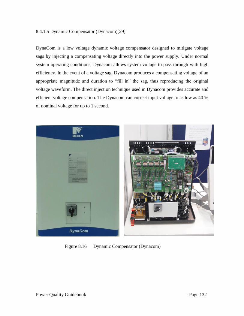
Power Quality Guidebook - Page 132-
8.4.1.5 Dynamic Compensator (Dynacom)[29]
DynaCom is a low voltage dynamic voltage compensator designed to mitigate voltage
sags by injecting a compensating voltage directly into the power supply. Under normal
system operating conditions, Dynacom allows system voltage to pass through with high
efficiency. In the event of a voltage sag, Dynacom produces a compensating voltage of an
appropriate magnitude and duration to ―fill in‖ the sag, thus reproducing the original
voltage waveform. The direct injection technique used in Dynacom provides accurate and
efficient voltage compensation. The Dynacom can correct input voltage to as low as 40 %
of nominal voltage for up to 1 second.
Figure 8.16 Dynamic Compensator (Dynacom)
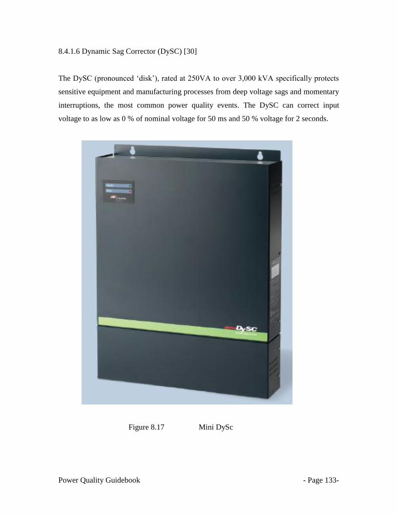
Power Quality Guidebook - Page 133-
8.4.1.6 Dynamic Sag Corrector (DySC) [30]
The DySC (pronounced ‗disk‘), rated at 250VA to over 3,000 kVA specifically protects
sensitive equipment and manufacturing processes from deep voltage sags and momentary
interruptions, the most common power quality events. The DySC can correct input
voltage to as low as 0 % of nominal voltage for 50 ms and 50 % voltage for 2 seconds.
Figure 8.17 Mini DySc
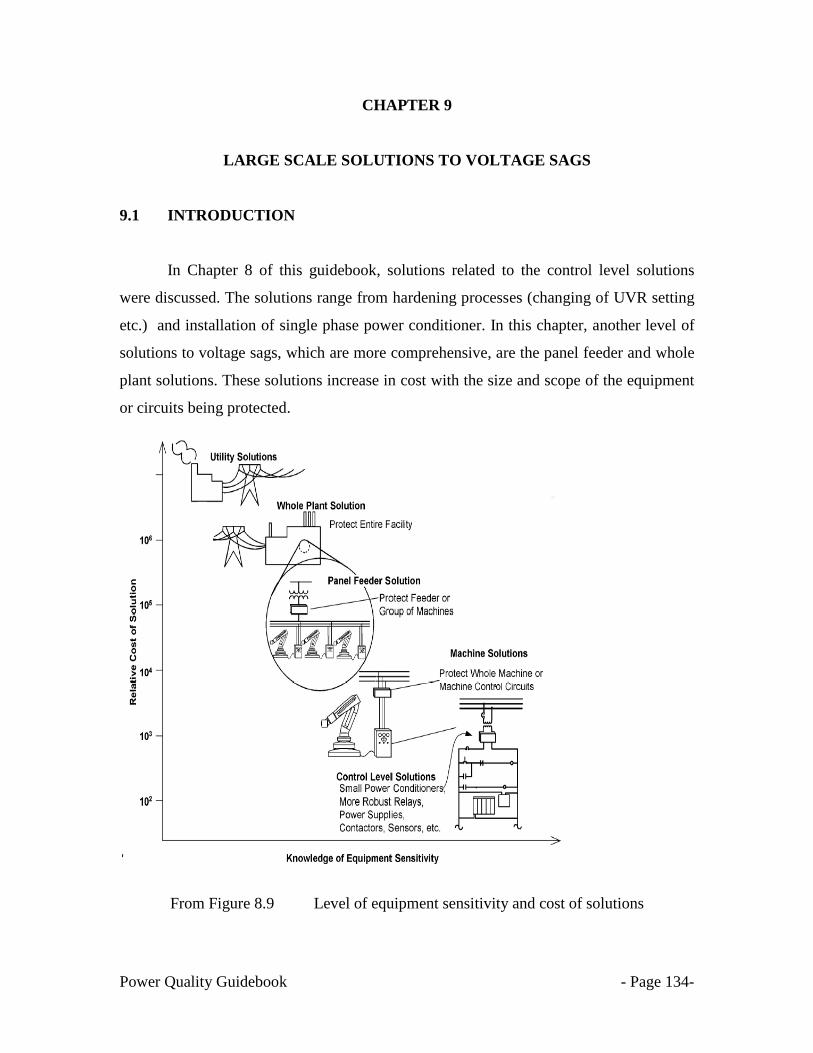
Power Quality Guidebook - Page 134-
CHAPTER 9
LARGE SCALE SOLUTIONS TO VOLTAGE SAGS
9.1 INTRODUCTION
In Chapter 8 of this guidebook, solutions related to the control level solutions
were discussed. The solutions range from hardening processes (changing of UVR setting
etc.) and installation of single phase power conditioner. In this chapter, another level of
solutions to voltage sags, which are more comprehensive, are the panel feeder and whole
plant solutions. These solutions increase in cost with the size and scope of the equipment
or circuits being protected.
From Figure 8.9 Level of equipment sensitivity and cost of solutions

Power Quality Guidebook - Page 135-
To achieve the large scale solutions for voltage sag requires the use of three-phase power
conditioners.
9.1.1 Sizing procedure for three phase power conditioners
The power conditioners must be installed at the panel feeder and whole plant solutions.
To size the power conditioner, please take the current & voltage values at the Main
Switch Board or Circuit Breaker. Examples of the sizing of the power conditioners are
shown in Figure 9.1. Select the next highest rating (kVA) for the power conditioner and
please consider any potential current inrush in sizing the power conditioner when starting
the equipment.
Once the size of the power conditioner is known, please choose the best three phase
power conditioner to protect the panel feeder and whole plant solutions from voltage
sags. Please refer to IEC standards requirement in subchapters 6.3.2.4 & 6.3.2.5.
Figure 9.1 Example on sizing of three phase power conditioner

Power Quality Guidebook - Page 136-
Descriptions of a few three-phase power conditioners available in the market are
described in this chapter.
9.2 Three Phase Uninterruptible Power Supplies (UPS)
An uninterruptible power supply (UPS) is a device that allows a computer or
electrical device to keep running for at least a short time when the primary power source
is lost. A UPS contains a battery that "kicks in" when the device senses a loss of power
from the primary source. A UPS will provide full power backup based on the limit of the
battery capacity, maybe 5 to 10 minutes. The size of the UPS ranges from 10kVA to
Megawatt Systems.
A UPS also provides protection from voltage sags and power surges. The down
side to this approach is only the battery systems.
Figure 9.2 Three Phase Uninterruptible Power Supplies (UPS)

Power Quality Guidebook - Page 137-
9.3 Active Voltage Conditioner (AVC) [31]
9.3.1 PCS100 AV-40
The PCS100 Active Voltage Conditioner (AVC) or Omniverter is an inverter-
based system that protects sensitive industrial and commercial loads from voltage
disturbances. The PCS100 AVC-40 provides fast, accurate voltage sag correction,
continuous voltage regulation and load voltage compensation. It has been optimally
designed to provide the required equipment immunity from the level of voltage sags
expected on the AC supply network.
Table 9.1 Technical specifications for PCS100 AVC-40
Details 40 % AVC
Protection for 3 phase sags 60 % remaining voltage to 100 %.
50 % remaining voltage to 90 %
Protection for 1 phase sag Single-phase sags down to 40 % remaining voltage
Nominal ratings range
40 % correction
150 to 3600 kVA @ 480 V
150 to 3600 kVA @ 400 V
150 to 1800 kVA @ 220 V
Figure 9.3 PCS100 AVC-40 & PCS100 AVC-20 Active Voltage Conditioners

Power Quality Guidebook - Page 138-
9.3.2 PCS100 AVC-20
The PCS100 AVC-20 is a power protection system designed for use by industrial
and large commercial operations in environments where an unstable network or utility
voltage affects productivity. The PCS100 AVC-20 ensures a continual, regulated supply
of utility voltage where electric infrastructure is stressed, unstable or unreliable.
Table 9.2 Technical specifications for PCS100 AVC-20
Details 20 % AVC
Full correction to 100% Yes
Continuous Regulation
+/-20% to +/-1%
+/-30% to +/-10%
Nominal ratings range 250 to 3300 kVA @ 380, 400, 415V
Active Voltage Conditioner
Omniverter is in the background
Figure 9.4 Active Voltage Conditioner & Omniverter installed in other countries
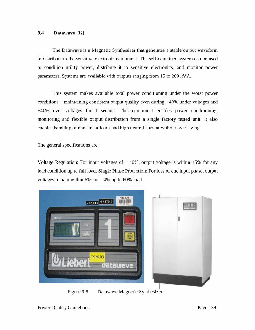
Power Quality Guidebook - Page 139-
9.4 Datawave [32]
The Datawave is a Magnetic Synthesizer that generates a stable output waveform
to distribute to the sensitive electronic equipment. The self-contained system can be used
to condition utility power, distribute it to sensitive electronics, and monitor power
parameters. Systems are available with outputs ranging from 15 to 200 kVA.
This system makes available total power conditioning under the worst power
conditions – maintaining consistent output quality even during - 40% under voltages and
+40% over voltages for 1 second. This equipment enables power conditioning,
monitoring and flexible output distribution from a single factory tested unit. It also
enables handling of non-linear loads and high neutral current without over sizing.
The general specifications are:
Voltage Regulation: For input voltages of ± 40%, output voltage is within +5% for any
load condition up to full load. Single Phase Protection: For loss of one input phase, output
voltages remain within 6% and –4% up to 60% load.
Figure 9.5 Datawave Magnetic Synthesizer

Power Quality Guidebook - Page 140-
9.5 Flywheel
A flywheel is a simple form of mechanical (kinetic) energy storage. Energy is
stored by causing a disk or rotor to spin on its axis. The stored energy is proportional to
the mass of the flywheel and the square of its rotational speed. Advances in power
electronics, magnetic bearings, and flywheel materials coupled with innovative
integration of components have resulted in direct current (dc) flywheel.
A flywheel together with a motor-generator (M/G) set can immunize critical processes
against all voltage sags. When a voltage sag occurs, the motor- generator set feeds the
load, the energy being supplied by slowing down the flywheel. Different connection
topologies of the flywheel to the M/G set exist of which Figure 10.3 shows the main
components of a connection using power electronics.
Figure 9.6 Flywheel
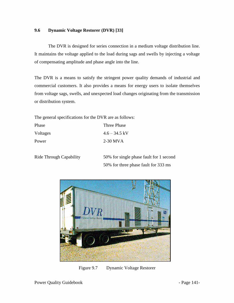
Power Quality Guidebook - Page 141-
9.6 Dynamic Voltage Restorer (DVR) [33]
The DVR is designed for series connection in a medium voltage distribution line.
It maintains the voltage applied to the load during sags and swells by injecting a voltage
of compensating amplitude and phase angle into the line.
The DVR is a means to satisfy the stringent power quality demands of industrial and
commercial customers. It also provides a means for energy users to isolate themselves
from voltage sags, swells, and unexpected load changes originating from the transmission
or distribution system.
The general specifications for the DVR are as follows:
Phase Three Phase
Voltages 4.6 – 34.5 kV
Power 2-30 MVA
Ride Through Capability 50% for single phase fault for 1 second
50% for three phase fault for 333 ms
Power quality problem
Power quality solution
Figure
F
Figure 9.7 Dynamic Voltage Restorer

Power Quality Guidebook - Page 142-
9.7 Three-phase Dynamic Compensator (Dynacom)
Under normal system operating conditions, DynaCom allows system voltage to pass
through with high efficiency. In the event of a voltage sag, DynaCom produces a
compensating voltage of an appropriate magnitude and duration to ―fill in‖ the sag, thus
reproducing the original voltage waveform. The direct injection technique used in
DynaCom provides accurate and efficient voltage compensation.
The specifications for the Dynacom are as follows:
Phase Three Phase
Voltages 208-690 volts
Power 342 - 987 kVA
Ride Through Capability 40% for 1 second
0% for 60 ms
Figure 9.8 Three phase Dynacom
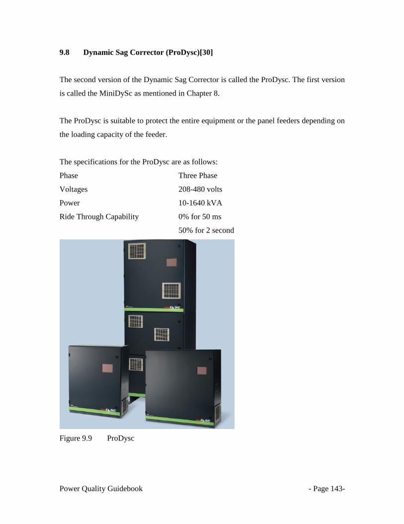
Power Quality Guidebook - Page 143-
9.8 Dynamic Sag Corrector (ProDysc)[30]
The second version of the Dynamic Sag Corrector is called the ProDysc. The first version
is called the MiniDySc as mentioned in Chapter 8.
The ProDysc is suitable to protect the entire equipment or the panel feeders depending on
the loading capacity of the feeder.
The specifications for the ProDysc are as follows:
Phase Three Phase
Voltages 208-480 volts
Power 10-1640 kVA
Ride Through Capability 0% for 50 ms
50% for 2 second
Figure 9.9 ProDysc

Power Quality Guidebook - Page 144-
9.9 Dynamic Sag Corrector (MegaDysc) [30]
The third version of the Dynamic Sag Corrector is called the MegaDysc. The MegaDysc
is suitable to protect whole panel feeders (process level) depending on the loading
capacity of the feeder. The specifications for the MegaDysc are as follows:
General Specifications
Phase Three Phase
Voltages 480 volts
Currents 400-2400 A
Power 333 kVA- 2 MVA
Figure 9.10 1 MVA MegaDySc

Power Quality Guidebook - Page 145-
9.10 UPS-I, Industrial UPS [34]
The PCS100 UPS-I is an industrially rated UPS designed specifically for the challenging
motor, AC drives, and other industrial loads. The PCS100 UPS-I is the ideal solution
where very deep sags or short term power outages occur. The PCS100 UPS-I uses energy
storage, coupled through an inverter to allow the downstream load to ride through very
deep sags and short term outages. The PCS100 UPS-I is an industrial, single conversion
UPS.
Table 9.3 Technical specifications for PCS100 UPS-I
Details PCS100 UPS-I
Batteries 30 Seconds autonomy
Ultracapacitors 2 seconds autonomy
Nominal ratings range 150 to 3000 kVA @ 480 V 50/60 Hz
150 to 3000 kVA @ 400 V 50 Hz
150 to 1500 kVA @ 220 V 50/60 Hz
Figure 9.11 PCS100 UPS-I, Industrial UPS
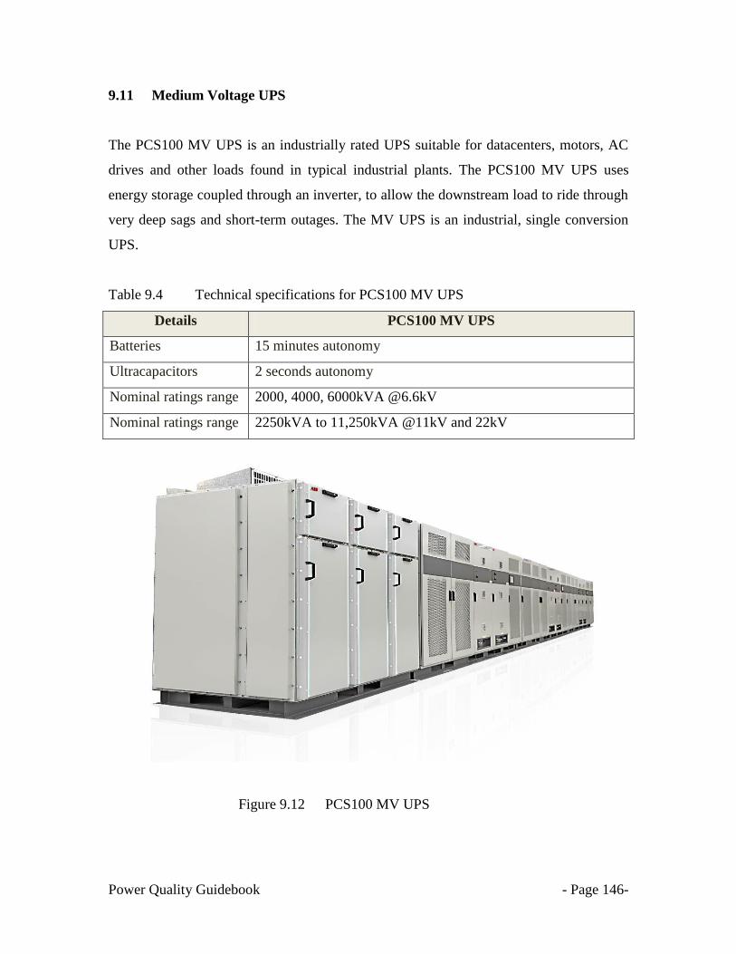
Power Quality Guidebook - Page 146-
9.11 Medium Voltage UPS
The PCS100 MV UPS is an industrially rated UPS suitable for datacenters, motors, AC
drives and other loads found in typical industrial plants. The PCS100 MV UPS uses
energy storage coupled through an inverter, to allow the downstream load to ride through
very deep sags and short-term outages. The MV UPS is an industrial, single conversion
UPS.
Table 9.4 Technical specifications for PCS100 MV UPS
Details PCS100 MV UPS
Batteries 15 minutes autonomy
Ultracapacitors 2 seconds autonomy
Nominal ratings range 2000, 4000, 6000kVA @6.6kV
Nominal ratings range 2250kVA to 11,250kVA @11kV and 22kV
Figure 9.12 PCS100 MV UPS
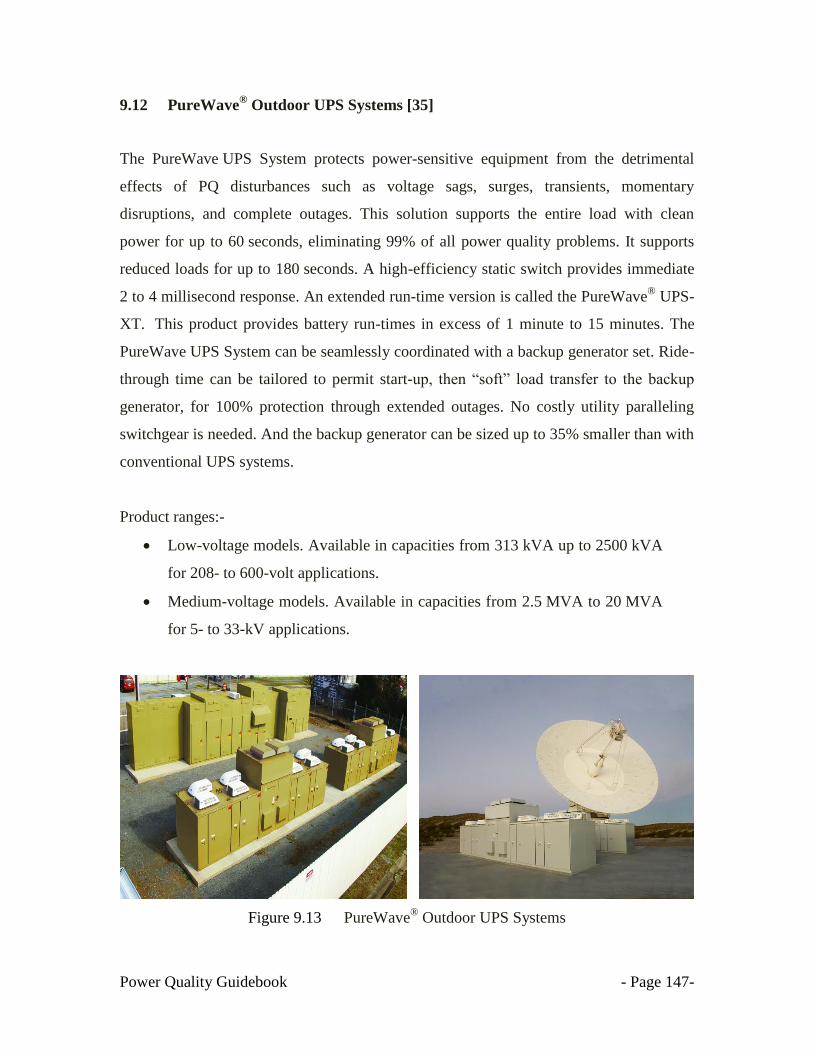
Power Quality Guidebook - Page 147-
9.12 PureWave® Outdoor UPS Systems [35]
The PureWave UPS System protects power-sensitive equipment from the detrimental
effects of PQ disturbances such as voltage sags, surges, transients, momentary
disruptions, and complete outages. This solution supports the entire load with clean
power for up to 60 seconds, eliminating 99% of all power quality problems. It supports
reduced loads for up to 180 seconds. A high-efficiency static switch provides immediate
2 to 4 millisecond response. An extended run-time version is called the PureWave® UPS-
XT. This product provides battery run-times in excess of 1 minute to 15 minutes. The
PureWave UPS System can be seamlessly coordinated with a backup generator set. Ride-
through time can be tailored to permit start-up, then ―soft‖ load transfer to the backup
generator, for 100% protection through extended outages. No costly utility paralleling
switchgear is needed. And the backup generator can be sized up to 35% smaller than with
conventional UPS systems.
Product ranges:-
Low-voltage models. Available in capacities from 313 kVA up to 2500 kVA
for 208- to 600-volt applications.
Medium-voltage models. Available in capacities from 2.5 MVA to 20 MVA
for 5- to 33-kV applications.
Figure 9.13 PureWave® Outdoor UPS Systems
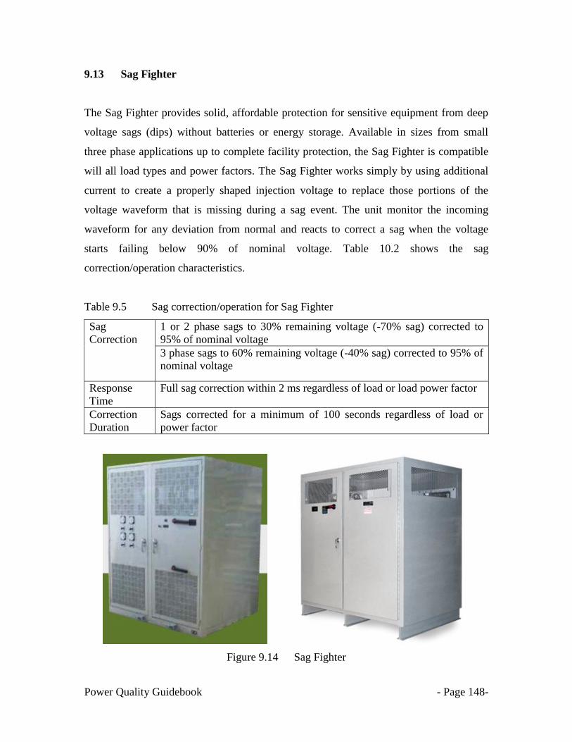
Power Quality Guidebook - Page 148-
9.13 Sag Fighter
The Sag Fighter provides solid, affordable protection for sensitive equipment from deep
voltage sags (dips) without batteries or energy storage. Available in sizes from small
three phase applications up to complete facility protection, the Sag Fighter is compatible
will all load types and power factors. The Sag Fighter works simply by using additional
current to create a properly shaped injection voltage to replace those portions of the
voltage waveform that is missing during a sag event. The unit monitor the incoming
waveform for any deviation from normal and reacts to correct a sag when the voltage
starts failing below 90% of nominal voltage. Table 10.2 shows the sag
correction/operation characteristics.
Table 9.5 Sag correction/operation for Sag Fighter
Sag
Correction
1 or 2 phase sags to 30% remaining voltage (-70% sag) corrected to
95% of nominal voltage
3 phase sags to 60% remaining voltage (-40% sag) corrected to 95% of
nominal voltage
Response
Time
Full sag correction within 2 ms regardless of load or load power factor
Correction
Duration
Sags corrected for a minimum of 100 seconds regardless of load or
power factor
Figure 9.14 Sag Fighter

Power Quality Guidebook - Page 149-
CHAPTER 10
SUMMARY OF GUIDEBOOK
According to IEC 61000-2-8 [10], voltage sags have been an intrinsic feature of
public electricity supply since the earliest times. Yet in recent decades they have become
an increasingly troublesome disturbance, giving rise to inconvenience and even
considerable economic loss. The reason is that some modern electricity utilisation
equipment, either in its own design or because of control features incorporated in it, has
become more sensitive to voltage sags. There is therefore a need for an increased
awareness of the phenomenon among the suppliers, customers of electricity and the
manufacturers of equipment using electricity.
This awareness must encompass all the conclusions already mentioned in this
guidebook, including the voltage and duration values observed, the frequency with which
voltage sag can occur and the variability of that frequency, with the uncertainty that
arises there from. The effect of a voltage sag on the customer‘s equipment must be
considered, with particular regard to the depth-duration characteristics that are critical,
and the customer must take due account of the possible consequences of any deterioration
of performance or lapse in operation of that equipment. In the light of those
consequences, the installation should, from the very first stage of planning, be designed
to minimise disturbance and loss arising from voltage sags, having regard to the
economic considerations that apply.
The normal approach to manage electromagnetic compatibility (EMC) is to
observe co-ordinated limits for both emission and immunity for the disturbance
phenomenon involved. The special constraints that apply to voltage sags and short
interruptions with regard to that approach have already been described—the limitation of
emissions is virtually impracticable, while intrinsic immunity can be obtained with proper
design requirement based on technical standard.
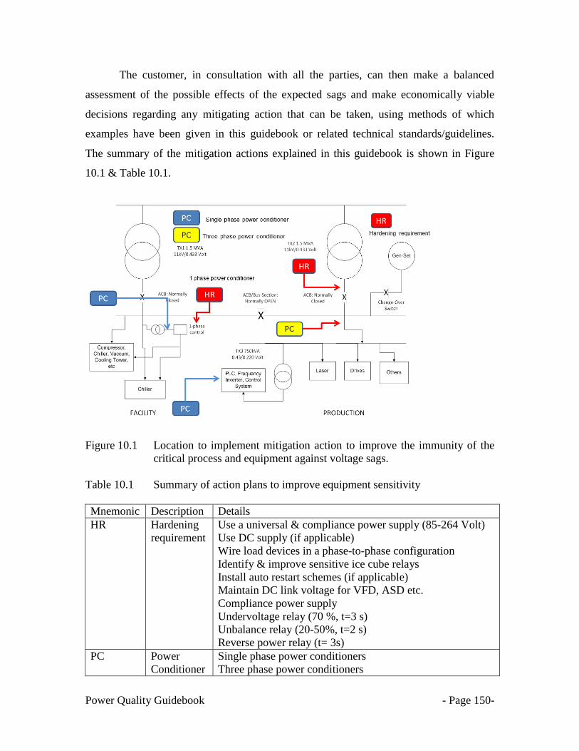
Power Quality Guidebook - Page 150-
The customer, in consultation with all the parties, can then make a balanced
assessment of the possible effects of the expected sags and make economically viable
decisions regarding any mitigating action that can be taken, using methods of which
examples have been given in this guidebook or related technical standards/guidelines.
The summary of the mitigation actions explained in this guidebook is shown in Figure
10.1 & Table 10.1.
Figure 10.1 Location to implement mitigation action to improve the immunity of the
critical process and equipment against voltage sags.
Table 10.1 Summary of action plans to improve equipment sensitivity
Mnemonic Description Details
HR Hardening
requirement
Use a universal & compliance power supply (85-264 Volt)
Use DC supply (if applicable)
Wire load devices in a phase-to-phase configuration
Identify & improve sensitive ice cube relays
Install auto restart schemes (if applicable)
Maintain DC link voltage for VFD, ASD etc.
Compliance power supply
Undervoltage relay (70 %, t=3 s)
Unbalance relay (20-50%, t=2 s)
Reverse power relay (t= 3s)
PC Power
Conditioner
Single phase power conditioners
Three phase power conditioners
Power Quality Guidebook - Page 151-
References
[1] IEEE Std.1100-1999, IEEE Recommended Practice for Powering and Grounding
[2] IEC Std. 61000-2-1, Electromagnetic compatibility (EMC) - Part 2: Environment:
Description of the environment - Electromagnetic environment for low-frequency
conducted disturbances and signaling in public power supply systems.
[3] IEEE 1159, IEEE Recommended Practice for Monitoring Electric Power Quality,
2009
[4] SEMI F47-0706 - Specification for Semiconductor Processing equipment Voltage
Sag Immunity
[5] http://www.leonardo-energy.org/sites/leonardo-
energy/files/root/pdf/2007/PQAADA_2007_Presentation%20Roman%20Targosz.
[6] http://www.powerqualityworld.com/2011/04/itic-power-acceptability-curve.html
[7] Cahier technique no. 149. EMC: electromagnetic compatibility by Jacques
DELABALLE, 2001
[8] http://www.copperinfo.co.uk/power-quality/downloads/pqug/542-standard-en-
50160-voltage-characteristics-in.pdf
[9] IEC 61000-2-4: Compatibility levels in industrial plants for low frequency
conducted disturbances.
[10] IEC 61000-2-8: Guide on voltage dips and short interruptions on Public Electric
Power Supply system
[11] http://www.electrotek.com/voltsag.htm
[12] Understanding Power Quality Problems (Voltage Sag and interruption), Math
Bollen, IEEE Press, 2000
[13] IEC 61000-4-30: Power Quality Monitoring Standard
[14] http://www.powerqualityworld.com/2011/04/voltage-sag-types-abc-
classification.html
[15] http://electrical-engineering-portal.com/transformer-routine-test-measurement-
voltage-ratio-phase-displacement
[16] http://f47testing.epri.com/voltage_dip_immunity.html

Power Quality Guidebook - Page 152-
[17] https://jointventure.org/images/stories/pdf/7_epri.multi-
level.approaches.for.mitigating.power.quality.issues.d1.pdf
[18] http://www.powerqualityworld.com/2011/04/cbema-curve-power-quality-
standard.html
[19] http://www.powerqualityworld.com/2011/04/itic-power-acceptability-curve.html
[20] http://f47testing.epri.com/f47abstract.html
[21] IEC 61000-4-11 Testing and measurement techniques –voltage dips, short
interruption and voltage variation immunity tests for
equipment less than 16 A per phase
[22] IEC 61000-4-34 Testing and measurement techniques –voltage dips, short
interruption and voltage variation immunity tests for
equipment more than 16 A per phase
[23] Chroma: www.chromausa.com
[24] Power Standards Lab USA: www.powerstandards.com
[25] http://ecmweb.com/archive/dealing-voltage-sags-your-facility
[26] http://www.pqsi.com/
[27] Dip Proofing inverter (DPI): www.dipproof.com
[28] Voltage Dip Compensator (VD.C): www.dipproof.com
[29] Dynamic Compensator (Dynacom): www.meidensg.com.sg
[30] Dynamic Sag Corrector (DySC): www.softswitching.com
[31] Active Voltage Conditioner (AVC):
www.abb.com/product/seitp322/e039976253ee76f8c12576f600410658.aspx
[32] Datawave: www.liebert.com
[33] PureWave DVR: www.sandc.com/edocs_pdfs/EDOC_030092.pdf
[34] UPS-I, Industrial UPS,
www.abb.com/product/seitp322/2747fc63c7439d8dc12576f6004073ea.aspx
[35] PureWave® Outdoor UPS Systems, www.sandc.com/products/power-
quality/purewave-ups.asp
Power Quality Guidebook - Page 153-
Contact Us
Tenaga Nasional Berhad (TNB) is
committed to maintaining and delivering a
reliable supply of electricity. We are
always pleased to provide further
information on power quality or EMC to
customers.
If you have any enquiry on power
reliability, power quality, EMC or energy
related matters, please contact the nearest
TNB office near you.
www.tnb.com.my
Power Quality Guidebook - Page 154-
Asset Management Standard & Design Standard
Distribution Network Division TNB