Embed Size (px)
Citation preview

1
CV-Series
High-Pressure Valves
USER GUIDE
369 Syringa Ridge
Sandpoint, ID 83864
281.782.8312
www.vindum.com
V:1.2 (3-07-17)

2
This page is intentionally blank.
Copyright 2005-2017
Vindum Engineering, Inc. All rights reserved. Reproduction or use of contents in any manner is prohibited without express permission from Vindum Engineering. While every precaution has been taken in the prepara-tion of this manual, the publisher assumes no responsibility for errors or omissions. Neither is any liability assumed for damages resulting from use of the information contained herein.

3
Table of Contents Chapter 1 General Overview .................................................................................................. 1
1.1 Configuration ............................................................................................................................ 1
1.2 Main O-Ring Seal Material ........................................................................................................ 1
1.3 Pressure Rating ......................................................................................................................... 1
1.4 Solenoid Pilot Valve .................................................................................................................. 2
1.5 Valve Temperature Rating ........................................................................................................ 2
1.6 Wetted Parts ............................................................................................................................. 2
1.7 Everything you need to operate your CV Valve ........................................................................ 2
1.8 Additional Information .............................................................................................................. 3
1.8.1 CV Valve Models .................................................................................................. 3
1.8.2 CV Valve Size ....................................................................................................... 4
Chapter 2 Understanding Your Valve ................................................................................... 5
2.1 Principles of Operation for the 2-Way Valve ............................................................................ 5
2.1.1 Possible Configurations of the 2-Way Valve .................................................................. 5
2.1.2 Direction of Flow ............................................................................................................ 5
2.2 Principles of Operation for the 3-Way Valve ............................................................................ 5
2.2.1 Possible Configurations of the 3-Way Valve .................................................................. 5 2.2.1.1 Open / Closed Position (A1 / B2) ...................................................................... 6 2.2.1.2 Closed / Open Position (B1 / A2) ...................................................................... 6 2.2.1.3 Open / Open Position (A1 / A2) ........................................................................ 6 2.2.1.4 Closed / Closed Position (B1 / B2) .................................................................... 6
Chapter 3 Solenoid Pilot Valves & Manifolds .................................................................... 7
3.1 Air Supply Requirements .......................................................................................................... 7
3.1.1 Air Input and Output ............................................................................................ 7
3.2 Electrical Power......................................................................................................................... 8
3.3.1 Power Failure Options.......................................................................................... 8
3.3 High Temperature CV Valves .................................................................................................... 9
Chapter 4 CV-200 Series & CV-400 Series Valve Maintenance.................................... 11

4
4.1 Tools You Will Need ................................................................................................................ 11
4.2 Disassembling the 2-Way Valve .............................................................................................. 11
4.3 Disassembling the Piston Assembly ........................................................................................ 12
4.4 Disassembling the Sleeve Assembly ....................................................................................... 12
4.5 Inspecting the Sleeve and Cone .............................................................................................. 13
4.6 Reassembling the Sleeve Assembly ........................................................................................ 13
4.7 Reassembling the Piston Assembly ......................................................................................... 14
4.8 Reassembling the 2-Way Valve ............................................................................................... 14
Chapter 5 CV-300 Series & CV-500 Series Valve Maintenance .................................. 17
5.1 Differences Between the CV 2-Way and 3-Way Valves .......................................................... 17
5.2 Disassembling the 3-Way Valve .............................................................................................. 17
5.3 Disassembling the Piston Assembly ........................................................................................ 18
5.4 Disassembling the Sleeve Assembly ....................................................................................... 18
5.5 Reassembling the Sleeve Assembly ........................................................................................ 18
5.6 Reassembling the Piston Assembly ......................................................................................... 18
5.7 Reassembling the 3-Way Valve ............................................................................................... 18
Chapter 6 Maintenance & Troubleshooting .................................................................... 21
6.1 Air Supply Problems ................................................................................................................ 21
6.1.1 Solenoid Pilot Valve Visual Check ................................................................................ 21 6.1.1.1 If the Light Goes On and Off for a Different Solenoid Pilot Valve................... 21 6.1.1.2 If No Light Goes On or Off ............................................................................... 22
6.1.2 Solenoid Pilot Valve Audio Check ................................................................................ 22 6.1.2.1 No “Air Escaping” Sound When CV Valves Are Opened & Closed .................. 22 6.1.2.2 The Air Supply is Not Dry ................................................................................ 22 6.1.2.3 The Air Pressure is Too Low ............................................................................ 23 6.1.2.4 The Air Pressure is Too High ........................................................................... 23 6.1.2.5 Constant “Air Escaping” Sound ....................................................................... 23 6.1.2.6 Compressed Air Supply Runs Out Quickly ...................................................... 24
6.2 Fluid Supply Problems ............................................................................................................. 24
6.2.1 Fluid Leaks from the CV Valve Bleed Port .................................................................... 24
6.2.2 Fluid Leaks Across a “Closed” Valve ............................................................................. 25
6.2.3 Fluid Leaks Into Air Tubes ............................................................................................ 25
6.2.4 Fluid is Not Traveling Properly ..................................................................................... 25
Appendix 1: Removal & Replacement of the Cone ........................................................ 27
Appendix 2: CV-210 & CV-310 Valve Components ......................................................... 30
Appendix 3: CV-405 & CV-505 Valve Components ......................................................... 31
Appendix 4: CV-410 & CV-510 Valve Components ......................................................... 32
Appendix 5: CV-420 & CV-520 Valve Components ......................................................... 33
Appendix 6: Commercially Available Parts ....................................................................... 34
A.6.1 Fluid Fittings .......................................................................................................................... 34
A.6.2 Pilot Valves / Air Manifold ........................................................................................................ 35
A.6.3 Lubricants and Adhesives ......................................................................................................... 35
Appendix 7: O-Ring Compatibility Chart............................................................................ 36
Appendix 8: Quote Request / Order Form ........................................................................ 37
Index ............................................................................................................................................. 38

6
This page is intentionally blank.

1
Chapter 1 1. General Overview
The Vindum Engineering CV High Pressure Valves are available in two configurations; either as a 2-position, on/off valve, or a 3-way, 4-position valve. The CV Valves are air-actuated, constant-volume valves with a switching time of less than .1 second. They are typically used as switching devices in high-pressure fluid flow systems. The valves are designed so that no fluid is displaced when they are opened or closed. This allows them to be useful in systems requiring constant volumes or constant pressures during the switching cycle.
All wetted parts on CV Valves utilize either 316 stainless steel, which is corrosion resistant, or Hastelloy© C-276, which is used for brine applications or highly corrosive fluids. Our standard valves have a temperature rating of 180°F (80°C). Valves with our high temperature option have a temperature rating of 320°F (160°C).
1.1 Configuration
Each CV Valve is customized to the needs of the user by utilizing the following options:
The CV Valve can be built as either:
• 2-Way, on/off valve, which uses a single solenoid pilot valve
• 3-Way, 4 position valve which uses 2 solenoid pilot valves. The 3-way, 4-position valve contains two inde-pendently operated valves that are connected with a center fitting (tee).
Solenoids to control the valve are sold separately. Solenoids can be ordered singly or in manifold with up to twelve stations.
1.2 Main O-Ring Seal Material The following materials are available for the wetted O-ring. The wetted O-ring material needs to agree with the fluid used. See Appendix 7 or online sources (such as the Parker O-ring handbook) for chemical combabil-ity • Aflas
• Buna
• Teflon™
• UHMW
• Viton
• Other materials on request
1.3 Pressure Rating The CV-Valves can have a pressure rating of either 5,000; 10,000; or 20,000 psi.

2
1.4 Solenoid Pilot Valve The solenoid pilot valves for the 85 to 115 psi air supply can be operated by either:
• 12 Vdc
• 24 Vdc
Note: The standard voltage is 12 Vdc, 24 Vdc is available on request.
1.5 Valve Temperature Rating
• Standard ambient temperature CV-Valves operate up to 180°F (80°C), and have push-in type air line fittings.
• Optional high temperature CV-Valves operate up to 320°F (160°C), and have compression type air line fittings
Note: air line fittings are the only difference between ambient and high temperature valves.
1.6 Wetted Parts There are two options of materials for the valve’s wetted parts, or the parts of the valve that will come in con-tact with the fluid: • 316 Stainless Steel for inert materials, or
• Hastelloy C-276 for corrosive materials or brine
1.7 Everything you need to operate your CV Valve • Valve
• High Pressure Fittings
• Pneumatic fittings
Sold Separately
• Solenoid Pilot Valves
• 1/8” air tubing

3
1.8 Additional Information
1.8.1 CV Valve Models
Table 1-1
CV VALVE MODELS
Valve
Model
Maximum
Pressure
Rating [PSI (Bar)]
Internal
Volume (cc)
Approximate
Flow
Coefficient (CP)
2-Way On-Off Valves
CV-210 10,000 (700) 0.11 .06
CV-405 5,000 (350) 0.44 .24
CV-410 10,000 (700) 0,44 .12
CV-420 20,000 (1400) 0.22 .03
3-Way 4 Position Valves
CV-310 10,000 (700) 0.31 .06
CV-505 5,000 (350) 1.08 .24
CV-510 10,000 (700) 0.74 .12
CV-520 20,000 (1400) 0.62 .03

4
1.8.2 CV Valve Sizes
Valve Size
Valve Model
Fittings (Autoclave Engineers)
Valve Dimensions
2-Way On-Off Valves
CV-210
W125 - 1/8” Speedbite
2” diameter x 1.695”
(5.0 cm x 4.3 cm)
CV-405 SW250 - 1/4” Speedbite
2.25” diameter x 1.95”
(5.7 cm x 4.9 cm)
CV-410
SW250 - 1/4” Speedbite
2.25” diameter x 1.95”
(5.7 cm x 4.9 cm)
CV-420
F250C - 1/4” High Pressure
2.25” diameter x 1.95”
(5.7 cm x 4.9 cm)
3-Way 4 Position Valves
CV-310
W125 - 1/8” Speedbite
2” diameter x 3.645”
(5.0 cm x 9.2 cm)
CV-505
SW250 - 1/4” Speedbite
2.25” diameter x 4.435”
(57 cm x 11.3 cm)
CV-510
SW250 - 1/4” Speedbite
2.25” diameter x 4.435”
(57 cm x 11.3 cm)
CV-520
F250C - 1/4” High Pressure
2.25” diameter x 4.435”
(57 cm x 11.3 cm)

5
Chapter 2
2. UNDERSTANDING YOUR VALVE
2.1 Principles of Operation for the 2-Way Valve Each CV 2-Way Valve contains two air supply tubes, A and B, which are connected to one solenoid-operated pilot valve. Pressurized air passes from the solenoid pilot valve through one of the air supply tubes into the 2-Way valve’s piston assembly. Within the piston as-sembly is a cone that serves as a “gate”, which either opens and al-lows fluid to flow or closes and stops fluid from flowing.
• Pressurized air passing through air supply tube A moves an inter-nal cone away from the A air supply port. Because the cone is pointed towards the A port, this causes the valve to open and flu-id to flow. This is considered the “open” position.
• Pressurized air passing through air supply tube B moves an inter-nal cone towards the A air supply port. This causes the valve to close and fluid to stop. This is considered the “closed” position.
• The C port is a pressure bleed port. It is designed to provide pres-sure relief in case fluid leaks out of the sleeve assembly. If fluid is leaking from the C-Port, there is a problem with your valve. See section 6.2.1.
2.1.1 Possible Configurations of the 2-Way Valve
The 2-Way CV Valve is an on/off valve. It can be configured in two ways, either normally open or normally closed. In case of a power failure, it can be set to open or to close. See section 3.2.1: Power Failure Options for information on valve configurations.
2.1.2 Direction of Flow The fluid can flow through the valve in either direction. Figure 2.1 shows the fluid coming in from the left side.
2.2 Principles of Operation for the 3-Way Valve The CV 3-Way Valve contains two piston assemblies, which are connected by a center fitting (tee), and four air supply tubes. Two air supply tubes run between each piston assembly and solenoid pilot valve. Two sole-noid pilot valves are then attached to an air manifold.
High Pressure
Air
Figure 2.1
Fluid
Path
CV-210 Closed Valve
CV-210 Open Valve

6
2.2.1 Possible Configurations of the 3-Way Valve Because the three-way CV Valve contains the equivalent of two 2-Way valves, it can be used as two independently operated on-off valves, or as a single 3-way, 4-position switching valve. The 3-way valve can be operated in the following four positions.
2.2.1.1 Open/Closed Position (A1 / B2) Fig. 2.2
• Air flows into air-inlet port A1, causing the cone inside of valve 1’s piston assembly to open.
• Air flows into air-inlet port B2 causing the cone in-
side of valve 2’s piston assembly to close.
2.2.1.2 Closed/Open Position (B1 / A2) Fig. 2.3
• Air flows into air-inlet port B1 causing the cone in-side of valve 1’s piston assembly to close.
• Air flows into air-inlet port A2 causing the cone in-
side of valve 2’s piston assembly to open.
2.2.1.3 Open/Open Position (A1 / A2) Fig. 2.4
• Air flows into air-inlet port A1 causing the cone inside of valve 1’s piston assembly to open.
• Air flows into air-inlet port A2 causing the cone inside
of valve 2’s piston assembly to open.
2.2.1.4 Closed / Closed Position (B1 / B2)
• Air flows into air inlet port B1 causing the cone inside of valve 1’s piston assembly to close.
• Air flows into air inlet port B2 causing the cone inside of valve 2’s piston assembly to close.
Figure 2.2 Open/Closed Valve
High pressure
air
Fluid Path
A1 C1 B1 B2 C2 A2
Valve 1 Valve 2
Figure 2.3 Closed/Open Valve
Fluid Path High pressure
air
A1 C1 B1 B2 C2 A2
Valve 1 Valve 2
A1 C1 B1 B2 C2 A2
Valve 1 Valve 2
High pressure
air
Fluid Path
Figure 2.4 Open/Open Valve
Figure 2.5 Closed/Closed Valve
Fluid Path
A1 C1 B1 B2 C2 A2
High pressure
air
Valve 1 Valve 2

7
Chapter 3
3. Solenoid Pilot Valves and Manifolds
The CV-Series Valves are completely air actuated. Air is taken into the air inlet and distributed to the solenoid pilot manifolds. The solenoid pilots then distribute and control the air flow to the valves.
3.1 Air Supply Requirements Because the CV Valves are completely air-actuated, 85 to 115 PSI of filtered air must be connected to the so-lenoid pilot valves at all times. Failure to maintain sufficient air pressure at the appropriate port on the CV Valves can result in valve malfunction, leakage and subsequent loss of control. Following are the air supply requirements for all CV Valves. • The air must be clean. • The air must be dry because moisture in the air supply will cause the solenoid pilot valves to rust and mal-
function. • The air must be oil-free. • The air must be 85 - 115 PSI (5.95 to 8.05 bar). If the air pressure is outside this range, the solenoid pilot
valves may stop working. A standard, filtered laboratory air supply from an air compressor is adequate if it meets the above criteria. The air compressor should be equipped with a dryer because water vapor in the air lines will cause the pilot valves to rust and malfunction. Tanks of compressed air should not be used as a pressurized air source. 3.1.1Air Input and Output CV Valves are air-actuated. Incoming air must be connected at the solenoid pilot valves’ air inlet port, as shown in Figure 3-1. The air inlet at the bottom of a single solenoid (marked with a “P”) has a 1/8” quick-disconnect fitting. This fitting should be connected to a pressurized air source (regulated at 85 - 115 PSI) with a 1/8” air line. Solenoids are also available in groups connected to a manifold for a common air supply, as shown in Figure 3-2. The manifold air intake uses a 1/4” airline connected to a quick-disconnect fitting.
Figure 3-2: Solenoids
A B
P (Air Inlet)
Figure 3-1: Solenoid Pilot Valve

8
The air inlet fittings on the CV Valves are plastic “quick disconnects”, the same as the outlet fittings on the solenoid pilot valves. Connect the solenoid pilot valves to the CV Valve using 1/8” nylon or Teflon™ tubing (Teflon™ tubing is used for high temperature applications).
NOTE: Before any of the air lines connecting the solenoid pilot valves to the CV Valves are disconnected, for any reason, some type of numbered or color-coded tags should be placed on each air line, each solenoid pilot valve fitting, and each CV Valve fitting to ensure the correct connections are made during reassembly.
3.2 Electrical Power The solenoid pilot valves require electrical power to re-direct air pressure from one valve port to another. If electrical power is lost, the solenoid pilot valves position themselves to their default; non-energized position and valve control is lost. When the solenoid pilot valve loses power, the “B” port of the soliniod valve be-comes pressurized and the “A” port has no pressure in it. In figure 3-3 the “B” port of the solenoid pilot valve becomes pressured and causes the valve to close. For this reason, electrical failure should be taken into con-sideration and the lines should be connected so that if a power failure does occur, a dangerous situation is not created.
3.2.1 Power Failure Options In case of electrical failure, the valves can be configured to either default to a closed or an open position. To set up a normally closed configuration, the “B” ports of the solenoid valve and CV Valve should be connected together, and the “A” ports should be connected together, as shown in figure 3-3. For a normally open con-figuration, the “B” port of the solenoid valve should be plugged into the “A” port of the CV Valve and vice versa, as shown in figure 3-4.
Figure 3-3 Normally Closed CV-210 Valve

9
In the case of the three way CV Valves, the Valves can be set to have both valves open or closed, or it can be set to have one valve remain open while the other closes. Although this configuration is not shown, set up the valve in the normally closed configuration, then swap the connections on the valve you wish to be nor-mally open. • If normally-closed operation is desired for a CV-310 Valve, connect the solenoid pilot valves to the CV-310
Valve as shown in Figure 3-5.
• If normally-open operation is desired for a CV-310 Valve, connect the solenoid pilot valves to the CV-310 Valve as shown in Figure 3-6.
3.3 High Temperature CV Valves
If you are connecting a high temperature CV Valve, the following two changes should be made when in-stalling the air lines: • The 1/8” tubing used for the air connection between the solenoid pilot valve and the CV Valve must be
made of Teflon™ instead of nylon • The inlet air line fittings on the CV Valve will be swage-type fittings with metal ferrules. The tubing is slid
through the back side of the threaded cap. The metal ferrule is then slid onto the end of the air line, and the threaded cap is firmly tightened onto the fitting, compressing the ferrule onto the air line.
If using CV Valves in an application where they are placed in an oven, the solenoid pilot valves must be placed outside of the oven, and the Teflon™ air lines connecting them to the CV Valves should be as short as possi-ble. Placing a solenoid pilot valve in an oven will destroy it. Do not use nylon air lines in an oven.
Figure 3-4: Normally Open CV-210 Valve
Figure 3-5: Normally Closed CV-310 Valve
A1
B1
B2
A2
A1 B1
A2 B2
A1
B1
B2
A2
Figure 3-6: Normally Open CV-310 Valve
A1 B1
A2 B2

10
This page is intentionally blank.

11
Chapter 4
4. CV-200 Series and CV-400 Series Valve Maintenance The information contained in Chapter 4 explains how to disassemble, reassemble, and service all of the CV-series on-off valves. Chapter 5 will explain how to service the 3-way valves. The piston assemblies and sleeve assemblies in the 3-way valves are relative to those used in the on-off valves, so most of the information in his chapter also pertains to 3-way valves. Figure 4-1 is an expanded view of the CV-210 Valve. The CV-400 Series valves are similar, except that they are slightly larger in size. Throughout this chapter, refer to Figure 4-1 for component numerical references, which will be shown in brackets. For example, the four 8-32 x 1/2" socket-head cap screws shown as number “1” will be referenced as “[1]”. 4.1 Tools You Will Need You will need the following tools in order to maintain your valves. • 1 each - 9/64 inch Allen wrench • 1 each - 1/2 inch adjustable wrench, or vice grip with cloth as to not damage end fitting • 2 each - 3/4 inch adjustable wrenches • 1 each – Wooden toothpick, plastic dental pick or nylon rod approximately 1/8” in diameter and tapered
at one end (No Metal)
Figure 4-1: Valve for CV-210, CV-405, or CV-410
4.2 Disassembling the 2-Way Valve To disassemble the CV-200 Series or the CV-400 Series valve, refer to Figure 4-1, above, while following the instructions below. 1. Unplug valve from all tubing it is attached to.
1 4 7 8 6 7 4 2
5 End Fittings
End Cap
3 Support Brack-
Socket Head Cap
Screws
O-Ring Piston
Assembly Cylinder Shell

12
2. Use a 9/64” Allen wrench to remove the two 8-32 x 1/2” socket head cap screws [1] securing the valve to the Support Bracket [3].
3. Remove the remaining six 8-32 x 1/2" socket-head cap screws [2] securing both End Caps [4] in place.
4. Grasp the valve in one hand and slide a 1/2” adjustable wrench onto one of the end fittings [5]. Use the wrench to rotate the End Fitting and End Cap in a clockwise direction while simultaneously applying force away from the body of the valve. When there is sufficient space between the End Cap and the Cylinder Shell [6], grasp the End Cap by hand and gently separate the two parts. As the End Cap begins to sepa-rate from the Cylinder Shell, continue to pull “straight back”, with a minimum amount of “rocking back-and-forth”.
NOTE: The End Fitting is permanently attached to the End Cap with “Loctite® 272”. 5. Inspect the polished stem on the End Fitting to make sure that it is free of scratches. If it is scratched, it
needs to be polished using 2,000 grit sandpaper. Polishing the stem is easiest if done on a lathe. 6. Repeat step 3 with the other end of the End Cap/End Fitting, and set both pairs of parts aside on a clean
work surface. 7. Gently slide the Piston Assembly [8] out of the Cylinder Shell [6], and set the Cylinder Shell aside. Note: you can remove the Piston Assembly from the Cylinder Shell easily without removing both end caps
by removing one end cap and activating the pressurized air to the air fitting opposite of the open end cap. Use as low of pressure air you can to remove the assembly, and make sure to catch the Piston Assembly as it pops out of the Cylinder Shell.
Figure 4-2: Piston Assembly

13
4.3 Disassembling the Piston Assembly Refer to Figure 4-2, above, for the following instructions. 1. Slide two 3/4” adjustable wrenches over the flats on the outside of both the Piston halves [11] and [13]. 2. Turn either one of the Piston halves counter-clockwise, while holding the other Piston stationary with the
wrench. After the two halves “break free”, continue to gently unscrew them by hand and set both pieces aside on a clean surface with their threaded sides “up”.
3. Remove the Sleeve Assembly [12] from the Left Piston by hand.
4.4 Disassembling the Sleeve Assembly Refer to Figures 4-3, 4-4, or 4-5 to Disassemble the Sleeve Assembly for your CV Valve. The Figures 4-3, 4-4, 4-5 use false colors for illustrative purposes. Teflon back-up rings are white, PEEK back-up rings are tan, and the O-ring color is material dependent.
Figure 4-3: Sleeve and Cone Assembly for CV-210 and CV-310
14 15 16 15 14 17 18 19 14 15 16 15 14
PEEK back-up
ring
Teflon™ back-up
Ring Main O-Ring
Seal Sleeve Cone Spacer
20 21 22 21 20 23 24 25 20 21 22 21 20
PEEK back-up
ring Main O-Ring
Seal
Teflon™ back-
up ring Sleeve
Cone Spacer
Figure 4-4: Sleeve and Cone Assembly for CV-405, CV-410, CV-505, and CV-510 Valves

14
1. Grasp the Sleeve Assembly and, using a toothpick or other appropriate tool; GENTLY slide it into the in-side of one of the PEEK (tan) Back-Up Rings [14] on either side of the Sleeve Assembly. Only slide the End Fitting (or tool) in far enough to capture the PEEK Back-Up Ring, but not the Teflon™ (white) Back-up Ring [15] or the O-ring [16].
2. Remove the PEEK Back-Up Ring. 3. The objective of this step is to remove the rings one at a time without damaging the inside surface of the
Sleeve. Repeat steps 1 and 2 for all remaining back-up and O-rings in the Sleeve Assembly, removing them one at a time, for both ends of the sleeve.
Note: The sleeve assembly is slightly different for each CV-Valve Model. The figures below show details for the CV-210 / CV-310 Valves, (Figure 4-3), the CV-405 / CV-410 / CV-505 and CV-510 Valves, (Figure 4-4) and the CV-420 / CV-520 Valves, (Figure 4-5).
4.5 Inspecting the Sleeve and Cone Now that the outside ring, O-rings, and the back-up rings are removed, wipe everything dry with a clean lint-free cloth. Look inside of the sleeve. Check to make sure the area inside of the sleeve where the O-ring sits is clean and scratch-free. If there is a build-up, or anything is stuck on the sleeve barrel, remove it. You may use a solvent and rag to clean the sleeve assembly. DO NOT use steel wool. If you see any scratches inside of the sleeve where the O-ring sits, a new O-ring may leak. Contact Vindum Engineering to purchase a replacement sleeve. Next inspect the cone [18, 24], which is inside of the sleeve. Check to make sure the cone has no scratches, nicks, cracks, or broken-off areas. Make sure the cone does not appear off-center or have an asymmetrical wear pattern. Proceed only if the cone appears in good condition. If the cone displays any of the above prob-lems, refer to Appendix 1 for information on replacing it. Replacement cones are available from Vindum Engi-neering. For CV-420 and CV-520 valves, the entire sleeve must be replaced if there is damage to the seat. To with-stand the high pressures these valves are capable of, the valve seat is permanently embedded in the sleeve.
4.6 Reassembling the Sleeve Assembly To reassemble the Sleeve Assembly, follow the instructions below.
Figure 4-5: Sleeve and Cone Assembly for CV-420 and CV-520 Valves
PEEK Back-
up ring
Teflon™ Back
-up Ring
Main O-ring Seal 26 27 30 26 27 28
29
Sleeve
Seat 28 27 26 26 27 27 26

15
1. Carefully slide the two PEEK (tan) Back-up Rings [14, 20 or 26] into both sides of the Sleeve, on top of the spacer [19 or 25] and one into the other side of the Sleeve. Press these Back-up Rings all the way down so
that they are seated flat. 2. Next, carefully slide the two Teflon™ (white) Back-up Rings [15, 21 or
27] into both sides of the Sleeve on top of the PEEK Back-up Rings. Again, press these Back-up Rings all the way down so that they are seated flat.
3. Gently insert the Main O-ring [16, 22, or 28] into each end of the
Sleeve. Prevent the O-rings from rolling or binding. When fully pressed in, the Main O-ring should be resting flat against the Teflon™ Back-up Ring.
4. Carefully slide a second Teflon™ Back-up Ring into each side of the
Sleeve on top of the Main O-rings. Press the Teflon™ Back-up Ring all the way down until it is seated flat against the Main O-ring.
5. Slide a second PEEK Back-up Ring into each side of the Sleeve. Make sure it is seated flat and does not
protrude outside the outer edge of the sleeve.
4.7 Reassembling the Piston Assembly Refer to Figure 4-2 to reassemble the Piston Assembly, following the instructions below. 1. The larger half of the Piston Assembly, the Left Piston [11] has male threads. Slide the Sleeve Assembly
[12] into this part with the point of the Cone facing out.
2. Gently screw the Right Piston into the Left Piston. When the two halves become “snug” use two 3/4” ad-justable wrenches to tighten them. Keep in mind which way the cone is facing.
3. As shown in Figure 4-2, each Piston half has two O-rings; one larger, external O-ring [10] and one smaller,
internal O-ring [9]. To remove any of these, use a tool such as a small wooden skewer or nylon rod, ap-proximately 1/8” in diameter and tapered at one end. Use care not to scratch or leave particles in the O-ring grooves.
4. Use the tapered end of the tool to gently remove any O-rings. For the larger, external O-rings, gently re-
place them but do not “roll” them into their respective grooves. When they are in place, they should not be twisted.
4.8 Reassembling the 2-Way Valve To re-assemble the Valve, follow the instruction below. 1. Replace the O-rings [7] on the End Caps [4], after verifying that there are no foreign particles of wood, or
any other materials, on any O-rings and that all O-rings are not twisted.
11
Figure 4-6: assembling the Piston
Assembly

16
2. Apply a small amount of high quality grease (not oil) to the external O-rings [10] and the smaller internal
O-rings [9]. Vindum Engineering uses Dow Corning 55 (M)® for ambient and high temperature valves
Vindum recommends Dupont® Krytox® for extra high temperature valves.
3. Gently slide the Piston Assembly into the Cylinder Shell. Place the piston so the “cone point” is facing
towards the “A” port of the cylinder shell. 4. The End Fittings [5] and Main O-rings [16, 22 or 28] must be lubricated on the surfaces that will slide into
the Piston. Apply a drop of lightweight oil on these surfaces on each End Fitting and spread the oil com-pletely around them. This oil should be compatible with the fluids with which this valve will be used.
5. Using a gentle rotating motion, slide both End Caps completely into both sides of the Cylinder Shell. 6. Use the 9/64” Allen wrench to replace the four 8-32 x 1/2" socket-head cap screws on the side of the Cyl-
inder Shell to which the cone is pointing. Tighten all four screws in a cross pattern snugly. 7. Use the Allen wrench to replace the two 8-32 x 1/2” screws securing the valve to the Support Bracket,
and the other two 8-32 x 1/2" screws into the end Cap on the bracket side. Note: The bracket is generally placed on the side of the valve containing the “B” port, with the valve cone
facing away from the bracket. However, depending on user preference, and changes during maintenance, the bracket may be on the side of the valve containing the “A” port. To avoid confusion, we recommend always placing the piston assembly into the cylinder shell such that the cone is always facing the “A” port.

17
Chapter 5
5. CV-300 Series and CV-500 Series Valve Maintenance The information contained in Chapter 5 explains how to disassemble, reassemble and service all of the CV Series 3-way valves. 5.1 Differences Between the CV 2-Way and 3-Way Valves The 3-way CV Valve contains all of the same sub-assemblies as the 2-way CV Valve. The 3-way valve is basi-cally two 2-way valves connected in the middle with a Center Fitting [40]. As shown in Figure 5-1, the Center Fitting is a symmetrical part with a “nipple-like” appendage on each side which fits into each of the Piston Assemblies. The Center Fitting also has an O-ring [39] on each side to provide a seal with the two Cylinder Shells. Instead of the Cylinder Shell being threaded on both sides to secure the End Caps, as with the 2-way valve, one Cylinder Shell is bored and one is threaded so that longer (2-1/2”) socket-head cap screws can be used to connect the two halves of the valve.
5.2 Disassembling the 3-Way Valve 1. Use a 9/64” Allen wrench to remove all of the 8-32 Socket Head Cap Screws [31,32] from both ends of the
valve. Separate the two “valve halves” by grasping the two Cylinder Shells by hand and gently twisting them in opposite directions while pulling them apart.
2. When the two valve halves have been separated, pull the Center Fitting [40] free of the Cylinder Shell
[37,38] it is still attached to, and set it aside. 3. Each half of the valve may now be disassembled as if it were a separate 2-way valve. 4. Grasp either of the halves of the 3-way valve in one hand and slide a 1/2" adjustable wrench onto one of
the End fittings [35]. Use the wrench to rotate the End Fitting and End Cap [36] in a clockwise direction while simultaneously applying force away from the body of the valve. When there is sufficient space be-tween the End Cap and the Cylinder shell [37] [38], grasp the End Cap by hand and gently separate the two parts. As the End Cap begins to separate from the Cylinder Shell, continue to pull “straight back”,
Figure 5-1: 3-Way Valve
41 41
Piston

18
with a minimal amount of “rocking back-and-forth”.
NOTE: The End Fitting is permanently attached to the End Cap with “Loctite® 272”.
5. Repeat step 4 with the other End Cap / End Fitting, and set both pairs of parts aside on a clean work sur-
face. 6. Gently slide the Piston Assemblies out of the Cylinder shells and set the Cylinder Shells aside.
5.3 Disassembling the Piston Assembly Refer to Chapter 4, Section 4.3 Disassembling the Piston Assembly for instructions (page 14).
5.4 Disassembling the Sleeve Assembly Refer to Chapter 4, Section 4.4 Disassembling the Sleeve Assembly for instructions (page 15).
5.5 Reassembling the Sleeve Assembly Refer to Chapter 4, Section 4.6 Reassembling the Sleeve Assembly for instructions (page 17).
5.6 Reassembling the Piston Assembly Refer to Chapter 4, Section 4.7 Reassembling the Piston Assembly for instructions (page 17).
5.7 Reassembling the 3-Way Valve To reassemble the valve, follow the instructions below. 1. Verify that there are no foreign particles of wood, or any other materials, on any O-rings. Make sure that
all O-rings are not twisted. 2. Replace the O-rings [39] on both End Caps [36]. 3. Gently slide the Piston Assembly into the Cylinder shell. Place a small piece of adhesive tape on the out-
side of the Cylinder Shell and draw an arrow on the tape pointing in the direction of the “cone point”. 4. On the 3-way valve, lubricate the stems on both sides of the Center Fitting [40]. The stems will slide into
the two Piston Assemblies. 5. Lubricate the narrow stems of each End Fitting [35]. 6. Lubricate the O-rings [39] on both sides of the Center Fitting being careful to keep lubrication off other
parts of the Center Fittings. 7. Lubricate the other two O-rings.

19
8. Making sure that the “cone points” are each facing AWAY FROM THE CENTER FITTING, gently slide each
of the Cylinder Shell / Piston Assemblies on to the Center Fitting. 9. Using a gentle rotating motion, gently slide both End Caps completely into both ends of the Cylinder
Shells. 10. Use the 3/4" adjustable wrench to rotate each of the End Caps until their four clearance holes are aligned
with those on the Cylinder Shells. Look through the clearance holes on each End Cap to see which End Cap is on the bored Cylinder Shell and carefully insert the 8-32 x 2-1/2” socket head cap screws [32] through the End Cap and the bored Cylinder Shell, just until the screws contact the Center Fitting.
11. Hold the Shell stationary, and gently rotate the Center Fitting until the screws can be passed through it. 12. Hold the bored Cylinder Shell and the Center Fitting stationary, and gently rotate the threaded Cylinder
Shell until the screws can be easily threaded into it. 13. Make sure that the Fluid Port on the Center Fitting, and the Air Fittings on the Cylinder Shells, are oriented in the correct direction relative to each other. 14. Use the 9/64” Allen wrench to tighten all four screws in a cross pattern snugly. 15. On the other End Cap, thread two 8-32 x 5/8” screws [31] through the Support Bracket [33] and into the
Cylinder Shell [37]. Make sure that the Fluid Inlet Port on the valve is facing the desired direction. 16. Use the Allen wrench to replace the remainder of the 8-32” socket-head cap screws. Tighten all screws
snugly.

20
This page is intentionally blank.

21
Chapter 6
6. Maintenance & Troubleshooting This chapter will help the user solve problems that might be encountered when operating the CV Valve. The following sections are included: • Air Supply Problems, Section 6.1 • Fluid Supply Problems, Section 6.2 • Valve Does Not Seal, Section 6.3 6.1 Air Supply Problems CV Valves are air actuated. Filtered air (85 to 115 PSI) must be connected to the solenoid pilot valves at all times. When encountering air supply problems, the first thing to do is complete the following two checks: • Solenoid Pilot Valve Visual Check, Section 6.1.1 • Solenoid Pilot Valve Audio Check, Section 6.1.2 Solenoid Pilot Valves are electrically operated to control air flow. They are used to open or close the fluid in-lets inside of CV Valves. The solenoid pilot manifold takes in air from the user’s air supply and distributes that air to the solenoid pilot valves. There is one solenoid pilot valve for each On/Off Valve and two solenoid pilot valves for each 3-Way Valve. When encountering air supply problems, the user should perform both the Solenoid Pilot Valve Visual Check and the Solenoid Pilot Valve Audio Check. 6.1.1 Solenoid Pilot Valve Visual Check The Solenoid Pilot Valve Visual Check confirms that the solenoid pilot valves are operating properly. Some solenoid pilot valves are equipped with a small red indicator light. When a valve is energized, the correspond-ing solenoid pilot valve indicator light turns ON and when a valve is de-energized, the corresponding solenoid pilot valve indicator light turns OFF. If the solenoid pilot valves on your CV Valve are equipped with indicator lights, perform the Solenoid Pilot Valve Visual Check on the fill and deliver side of each CV Valve in your sys-tem. 1. Open and close each CV Valve, using either a computer or manual means, depending on the type of in-
stallation the valve uses. 2. As each CV Valve is opened, confirm the corresponding solenoid pilot light comes on. 3. As each CV Valve is closed, confirm the corresponding solenoid pilot light turns off. 6.1.1.1 If the Light Goes On and Off for a Different Solenoid Pilot Valve If the light activates for a different solenoid pilot valve than the one you are controlling on the computer, the solenoid pilot cables are switched and must be re-connected properly.

22
6.1.1.2 If No Light Goes On or Off If no light goes on or off while conducting the solenoid pilot visual check, do the following: • Check that the proper voltage and the proper polarity is connected to the solenoid pilot valve(s)
6.1.2 Solenoid Pilot Valve Audio Check Listen for an “air escaping” sound when the solenoid pilot valve opens and closes. The sound should be easy to hear. It will not be a clicking sound. The clicking sound you may hear is simply the solenoid pilot valve opening or closing. The “air escaping” sound is the same as when you open a can or bottle that is under pres-sure and you hear an immediate gust of air. It is important that you hear this sound when the solenoid pilot valve opens and closes. If you do not hear the “air escaping” sound when each valve is opened and closed, then there is not adequate air pressure to operate the valves. Go back and check that your air tubing has been connected properly and that it is securely attached. If your air supply has a switch to turn it on, make sure the switch is turned on. Perform the Solenoid Pilot Valve Visual Check and Solenoid Pilot Valve Audio Check on all the solenoid pilot valves in your system. If, after completing the Solenoid Pilot Valve Visual Check and Solenoid Pilot Valve Audio Check, there is still an air supply problem, the following sections may help you in correcting the problem. • No “Air Escaping” Sound When Valves are Opened and Closed, Section 7.1.2 • Constant “Air Escaping” Sound, Section 7.1.3 6.1.2.1 No “Air Escaping” Sound When CV Valves Are Opened & Closed If you do not hear the “air escaping” sound when each valve is opened and closed, then there is not adequate air pressure to operate the valves. • Check if there are any kinks in the air tubing which runs between the solenoid pilot valves and the CV
Valves. • Check your air tubing has been connected properly and is securely attached. • If your air supply has a switch to turn it on, make sure the switch is turned on. • Make sure the pressurized air supply is a minimum of 85 PSI (5.7 bar). 6.1.2.2 The Air Supply is Not Dry The air supplied to the CV Valve must be clean and dry. If the air supply is not dry, the solenoid pilot valves may have rusted and stopped switching, which would result in no “air escaping” sound when opening and closing the valves. To check this, do the following. 1. Turn off your air supply. 2. Unplug your air line.

23
3. `Check if there is any fluid in the line. 4. If the solenoid pilot valves have rusted and no longer operate, they need to be replaced. 6.1.2.3 The Air Pressure is Too Low Another cause of no “air escaping” sound when opening and closing a valve is the air pressure is too low to operate the valves. Use a pressure gauge to determine the actual air pressure. If the air pressure is too low: • Check that your air tubing has been connected properly. • If your air supply has a switch to turn it on, make sure the switch is turned on. 6.1.2.4 The Air Pressure is Too High CV Valves need an air supply between 85 and 115 PSI (5.7 to 7.7 bar) to operate. If the air pressure is too high (more than 115 PSI (7.7 bar)), install an air regulator to limit the air pressure. 6.1.2.5 Constant “Air Escaping” Sound If you hear a constant “air escaping” sound when the valves are not being operated, then there is an air leak. Check the following areas to determine the cause of the air leak. • Verify that the plastic washers on all air fittings are present and not damaged. • Check each air tube to see if it is cracked or damaged. Replace any cracked or damaged air tube. • Verify that all air tubes are fully inserted into the quick-disconnect or compression fittings. All air tubing
should be able to withstand a “slight” tug when properly inserted and the fittings have been tightened. • Verify that all compression fittings are fully tightened. • Try using a soap and water solution to detect small leaks. • If air is escaping from the CV Valve Bleed Port, air is bypassing either the Piston External O-ring [10] or the
Piston Internal O-ring [9]. 1. Inspect the Piston External O-rings and the Piston Internal O-rings. Make sure they are not damaged and are free of contaminants. 2. Verify that the Piston External O-rings and Piston Internal O-rings are properly inserted. They should be smooth, free of nicks and not twisted. 3. If any problems exist, replace and re-grease the O-rings.

24
• If you suspect air is escaping from the solenoid pilot valves, try the following. 1. Sometimes a solenoid pilot valve will get stuck part way open or part way closed and allow air passage. Try opening and closing the valve to get the soliniod unstuck and moved to a fully open or fully closed position. Opening and closing a solenoid pilot valve a few times may free up a stuck solenoid pilot. If this does not work, the solenoid pilot valve may have to be re placed so it does not constantly leak air. 2. Verify that all solenoid pilot valves are securely screwed down to their manifold.
3. Verify that the gasket between the solenoid pilot valve and the air manifold is not damaged or cracked. If the gasket is cracked, contact Vindum Engineering for a replacement.
4. If air continues to escape from the area between the solenoid pilot valve and the manifold, apply a light coat of silicone based compound (Dow –Corning Compound 111 Valve Lubricant and Sealant, or equivalent) to the gasket between the solenoid pilot valve and the air mani fold. 6.1.2.6 Compressed Air Supply Runs Out Quickly Tanks of compressed air are not recommended as a pressurized air source. Only a continuous air supply should be used as the air source and air compressors need to be equipped with a dryer. 6.2 Fluid Supply Problems If the valve leaks, either of the following can occur: • It can leak to the outside, in which case the fluid will come out the bleed port located between the air in-
lets. • The cone will let fluid pass by it. • Fluid can leak from one of the high-pressure fittings. 6.2.1 Fluid Leaks from the CV Valve Bleed Port If fluid is coming out the Bleed Port, fluid is going by one of the main O-ring seals. To determine where the problem is, follow the steps below. • On the Piston Assembly, inspect the piston internal O-ring. Make sure it is not damaged and is free of
wear. If there are any signs of damage or wear, replace the O-ring. Also, make sure the piston internal O-ring is free of contaminants. If contaminants are present, replace the O-ring.
• Inspect the smooth stem of the end fitting for scratches. If a scratch is present the O-ring will not be able
to properly seal, therefore the end fitting would need to be replaced or polished with 2000 grit polishing paper.
• Check the inside surface of the sleeve. (The sleeve is part of the Sleeve Assembly, which is located inside

25
of the Piston Assembly.) Make sure there are no scratches on the inside surface of the sleeve. If scratches are present, the sleeve must be replaced.
• For the 3-way valves, also check the Center Fitting. Make sure there are no scratches on the stems of the
Center Fitting. If scratches are present, the center fitting should be replaced or the stems should be pol-ished with 2000 grit polishing paper.
6.2.2 Fluid Leaks Across a “Closed” Valve If the fluid is passing through the valve, or it does not hold pressure when it should be closed, this indicates that fluid is leaking by the closing cone. • Verify the pressurized air source is 85 to 115 PSI. • Inspect the Sleeve Assembly cone for signs of damage or wear at the sealing point. Replace if damage or
wear is visible. • Inspect the Sleeve Assembly for contaminants blocking the cone. If contaminants are present, remove the
contaminants making sure that they have not left an indent in the cone, End Fitting, or the conical seat in the End Fitting.
6.2.3 Fluid Leaks into Air Tubes The most likely cause of fluid leaking from the air tubes is water vapor is present in the pressurized air source. • Verify that the air compressor is equipped with a dryer and that the dryer is functioning properly. NOTE: If the air compressor being used is not equipped with a dryer, or if the dryer is not working properly, water vapor will eventually travel to the pilot valves. This will cause the pilot valves to rust and not work properly.
6.2.4 Fluid is Not Traveling Properly
If the fluid is not following the expected path at the expected time, do the following:
• The solenoid pilot valve air tubes are not connected properly. Manually trace each air tube to its destina-
tion to determine which tubes go to which valve. Check to see if the tubes are connected in the proper configuration for your setup. See Chapter 3 for the correct tubing configurations.

26
This Page Intentionally Left Blank

27
APPENDIX 1
Removal and Replacement of the Cone in the Sleeve Assembly
In the CV-200 and CV-300 Series of valves, the Cone [18] and Spacer [19] are “press-fit” into the Sleeve As-sembly. In the CV-405, 410, 505, and 510 series of valves, the cone must be removed with a specialized tool, available from Vindum Engineering In the CV-420 and CV-520 series of valves, however, the Cone cannot be pressed out, and if the valve seat is damaged the sleeve assembly must be replaced.
Removing and replacing the cone from the sleeve assembly requires a specialized tool, available from Vin-dum Engineering
Figure A.1.1 Removing the Cone and Spacer from the Sleeve Assembly
Removing the Cone and Spacer in the CV-200 and CV-300 Series of Valves 1. To remove the “press-fitted” Cone and Spacer (figure A.1.1), place the Sleeve Assembly on a metal sup-
port plate at least 1-inch thick on an arbor press. The “point” of the Cone should be pointing down. The support plate must have an opening in it so that the Sleeve is supported, but its inside diameter is unob-structed so the Cone and Spacer can be pushed completely through and out of the Sleeve.
2. Use a thin rod of hardwood or plastic with an outside diameter of 3/16” to press from the backside of the
Hardwood rod
Cone
Spacer
Metal Support Plate

28
Figure A.1.2 Reinstalling the Cone and Spacer in the Sleeve Assembly
Reinstalling the Cone and Spacer in the CV-200 and CV-300 Series of Valves
Looking at the inside diameter of the Sleeve [20] from both sides, notice that on one side the inside shoul-der is “farther down” or deeper than it is when looking from the other side. Place the sleeve on a flat sur-face with this “deeper” side up.
Using an arbor press and the cone install tool shown in Figure A.1.2, above, one at a time carefully press the Cone [18] and the Spacer [19] into the Sleeve. Be sure that the “point” of the Cone is facing “up” to-wards the outside of the Sleeve, as shown, as the Cone and Spacer are both pressed in all the way to the shoulder.
Cone Install Tool
Cone
Sleeve
Cone as shown below. Use the arbor press and the thin rod to push the Cone and Spacer out of the Sleeve.

29
Removing the Cone and Spacer from the CV-405,410,505, and 510 Series of Valves
Using a toothpick or other non-metal tool used to remove the back-up rings and O-rings from the sleeve, gently pull the spacer out of the sleeve. Unlike the CV-210 and CV-310 valves, the spacer is not press fitted into the sleeve, and should remove easily. Then line up the prongs on the cone removal tool (figure A.1.3) with the cone removal holes on the cone (shown in green in Figure A.1.4 and A.1.5) do not place the cone removal tool in the fluid flow holes (shown in blue in Figures A.1.4 and A.1.5). Unscrew the cone from the sleeve and remove it (Figure A.1.6).
Replacing the Cone and Spacer for the CV-405, 410, 505, and 510 Series of Valves
Place the cone into the deeper side of the sleeve with the threads facing into the sleeve. Place the cone re-moval tool’s prongs into the cone removal holes (shown in green in figures A.1.4 and A.1.5.) and retighten the cone until hand-tight. Do not overtighten, as you might strip the threads on the cone.
Figure A.1.3
Figure A.1.4
Figure A.1.5
Figure A.1.6

30
APPENDIX 2
CV-210 and CV-310 Valve Components
Valve Assembly - Refer to Figure 4-1 on page 11 or ( Figure 5-1) on page 17.
Piston Assembly - Refer to Figure 4-2 on page 12.
Sleeve and Cone Assembly - Refer to Figure 4-3 on page 13.
*Available in Stainless Steel and Hastelloy.
** Wetted O-ring, Item #16, available in several different materials.
NOTE: O-rings are Viton unless otherwise specified.
Figure
Number
Description
CV-210 VALVE
Quantity / Part Number
CV-310 VALVE
Quantity / Part Number
1 & (31)
2 & (32)
Socket Head Cap Screw 8 8-32 x 1/2-SHSS 4 8-32 x 1/2-SHSS
(34) Socket Head Cap Screw NA 4 8-32 x 2-1/2-SHSS
3 &(33) Support Bracket 1 410090 1 440060
4 & (36) End Cap 2 440070 2 440070
5 & (35) End Fittings 2 440040* 2 440040*
6 & (37) Cylinder Shell 1 440100-TH 1 440100-TH
(38) Cylinder Shell NA 1 440100-BO
7 & (39) O-Ring 2 2-028 4 2-028
8 & (41) Piston Assembly 1 460190* 2 460190*
(40) Center Fitting NA 1 440050*
Figure
Number
Description
CV-210 VALVE CV-310 VALVE
9 O-Ring (Internal) 2 2-014 4 2-014
10 O-Ring 2 2-125 4 2-125
11 Piston (Male) 1 440110 2 440110
12 Sleeve Assembly 1 460180* 2 460180*
13 Piston (Female) 1 440120 2 440120
Figure
Number
Description
CV-210 VALVE
Quantity / Part Number
CV-310 VALVE
Quantity / Part Number
14 PEEK Back-up Ring 4 410301 8 410301
15 Teflon™ Back-up Ring 4 410302 8 410302
16 Main O-ring Seal 2 2-008** 4 2-008**
17 Sleeve 1 440010* 2 440010*
18 Cone 1 410030 2 410030
19 Spacer 1 410100 2 410100

31
APPENDIX 3
CV-405 and CV-505 Valve Components
Valve Assy - Refer to Figure 4-1 on page 11 or (Figure 5-1) on page 17.
Piston Assembly - Refer to Figure 4-2 on page 12.
Sleeve and Cone Assembly - Refer to Figure 4-4 on page 13.
*Available in Stainless Steel and Hastelloy.
** Wetted O-ring, Item #22, available in several different materials.
NOTE: O-rings are Viton unless otherwise specified
Figure
Number
Description
CV-405 VALVE
Quantity / Part Number
CV-505 VALVE
Quantity / Part Number
1 & (31)
2 & (32)
Socket Head Cap Screw 8 8-32 x 1/2-SHSS 4 8-32 x 1/2-SHSS
(34) Socket Head Cap Screw NA 4 8-32 x 3-SHSS
3 & (33) Support Bracket 1 480060 1 480060
4 & (36) End Cap 2 480070 2 480070
5 & (35) End Fittings 2 480046 2 480046*
6 & (37) Cylinder Shell 1 480100-TH 1 480100-TH
(38) Cylinder Shell NA 1 480100-BO
7 & (39) O-Ring 2 2-030 4 2-030
8 & (41) Piston Assembly 1 460190* 2 460190*
(40) Center Fitting NA 1 480055*
Figure
Number
Description
CV-405 VALVE
Quantity / Part Number
CV-505 VALVE
Quantity / Part Number
9 O-Ring (Internal) 2 2-014 4 2-014
10 O-Ring 2 2-129 4 2-129
11 Piston (Male) 1 480110 2 480110
12 Sleeve Assembly 1 480185* 2 480185*
13 Piston (Female) 1 480120 2 480120
Figure
Number
Description
CV-405 VALVE
Quantity / Part Number
CV-505 VALVE
Quantity / Part Number
20 PEEK Back-up Ring 4 480020 8 480020
21 Teflon™ Back-up Ring 4 480025 8 480025
22** Main O-ring Seal 2 2-010** 4 2-010**
23* Sleeve 1 480010* 2 480010*
24 Cone 1 480030 2 480030
25 Spacer 1 480105 1 480105

32
APPENDIX 4
CV-410 and CV-510 Valve Components
Valve Assy - Refer to Figure 4-1 on page 11 or (Figure 5-1) on page 17.
Piston Assembly - Refer to Figure 4-2 on page 12.
Sleeve and Cone Assembly - Refer to Figure 4-4 on page 13.
*Available in Stainless Steel and Hastelloy.
** Wetted O-ring, Item #22, available in several different materials.
NOTE: O-rings are Viton unless otherwise specified.
Figure
Number
Description
CV-410 VALVE
Quantity / Part Number
CV-510 VALVE
Quantity / Part Number
1 & (31)
2 & (32)
Socket Head Cap Screw 8 8-32 x 1/2-SHSS 4 / 8-32 x 1/2-SHSS
(34) Socket Head Cap Screw NA 4 8-32 x 3-SHSS
3 & (33) Support Bracket 1 480060 1 480060
4 & (36) End Cap 2 480070 2 480070
5 & (35) End Fittings 2 480045* 2 480045*
6 & (37) Cylinder Shell 1 480100-TH 1 480100-TH
(38) Cylinder Shell NA 1 480100-BO
7 & (39) O-Ring 2 2-030 4 2-030
8* & (41)* Piston Assembly 1 480195* 2 480195*
(40) Center Fitting NA 1 480055*
Figure
Number
Description
CV-410 VALVE
Quantity / Part Number
CV-510 VALVE
Quantity / Part Number
9 O-Ring (Internal) 2 2-014 4 2-014
10 O-Ring 2 2-129 4 2-129
11 Piston (Male) 1 480110 2 480110
12* Sleeve Assembly 1 480185* 2 480185*
13 Piston (Female) 1 480120 2 480120
Figure
Number
Description
CV-410 VALVE
Quantity / Part Number
CV-510 VALVE
Quantity / Part Number
20 PEEK Back-up Ring 4 480020 8 480020
21 Teflon™ Back-up Ring 4 480025 8 480025
22** Main O-ring Seal 2 2-010** 4 2-010**
23* Sleeve 1 480010* 2 480010*
24 Cone 1 480030 2 480030
25 Spacer 1 480105 2 480105

33
APPENDIX 5
CV-420 and CV-520 Valve Components
Valve Assembly - Refer to Figure 4-1 on page 11 or (Figure 5-1) on page 17.
Piston Assembly - Refer to Figure 4-2 on page 12.
Sleeve and Cone Assembly - Refer to Figure 4-5 on page 15.
*Available in Stainless Steel and Hastelloy.
** Wetted O-ring, Item #28, available in several different materials.
NOTE: O-rings are Viton unless otherwise specified.
Figure
Number
Description
CV-420 VALVE
Quantity / Part Number
CV-520 VALVE
Quantity / Part Number
1 & (31)
2 & (32)
Socket Head Cap Screw 8 8-32 x 1/2-SHSS 4 8-32 x 1/2-SHSS
(34) Socket Head Cap Screw NA 4 8-32 x 3-SHSS
3 & (33) Support Bracket 1 480060 1 480060
4 & (36) End Cap 2 480070 2 480070
5 & (35) End Fittings 2 480130* 2 480130*
6 & (37) Cylinder Shell 1 480100-TH 1 480100-TH
(38) Cylinder Shell NA 1 480100-BO
7 & (39) O-Ring 2 2-030 4 2-030
8* & (41*) Piston Assembly 1 480200* 2 480200*
(40) Center Fitting NA 1 480050*
Figure
Number
Description
CV-420 VALVE CV-520 VALVE
9 O-Ring (Internal) 2 2-014 4 2-014
10 O-Ring 2 2-129 4 2-129
11 Piston (Male) 1 480110 2 480110
12 Sleeve Assembly 1 480186* 2 480186*
13 Piston (Female) 1 480120 2 480120
Figure
Number
Description
CV-420 VALVE
Quantity / Part Number
CV-520 VALVE
Quantity / Part Number
26 PEEK Back-up Ring 4 480020 8 480020
27 Teflon™ Back-up Ring 4 480025 8 480025
28** Main O-ring Seal 2 2-010** 4 2-010**
29* Sleeve 1 480011* 2 480011*
30 Seat 1 480140 2 480140

34
APPENDIX 6
Commercially Available Parts
A.6.1 Fluid Fittings
* The wetted material for the valves is listed on the warranty card.
Description Manufacturer Part Number Notes
Fitting Sleeve* CV210 / CV-310
Autoclave SSL20 XX XX is material type:
SS for Stainless 316
HC for Hastelloy C-276
Fitting Sleeve*
CV-405, CV-410
CV-505, CV-310
Autoclave SSL40 XX XX is material type:
SS for Stainless 316
HC for Hastelloy C-276
Collar
CV-420, CV-520
Autoclave ACL-40-316
Fitting Nut
CV-210, CV-310
Autoclave SMN20
Fitting Nut
CV-405, CV-410
CV-505, CV-510
Autoclave SMN40
Fitting Nut
CV-420, CV-520
Autoclave AGL-40-316
1/8 inch Tubing Vindum .125” OD x .035” wall SS-316
Hastelloy C-276
1/4 inch Tubing
(5 – 10 kpsi)
Vindum
.250” OD x .065” wall
SS-316
Hastelloy C-276
1/4 inch Tubing
(20 kpsi)
Vindum
.250” OD x .083” wall
SS-316
Hastelloy C-276

35
A.6.2 Pilot Valves / Air Manifold
A.6.3 Lubricants And Adhesives
Description Manufacturer Part Number Notes
Pilot Valve SMC SYJ5120-XL0Z-M5
X is 6 for 12 volt, 5 for 24 volt.
Verify that number on side of pilot valve is SYJ5120 and voltage is correct.
Air Manifold SMC SYJ5-20-XX-00T
XX is number of stations, 2 to 20. This manifold accepts SYJ5120 pilot valves. Verify pilot valve is SYJ5120 before pur-
Wire and Electrical Con-nector for Pilot Valve
SMC SY100-30-4A-XX X is length of wire in decimeters. (e.g., X is nil for 300 mm (12”), 6 for 600 mm (24”), 30 for 3 m (120”). This connector fits in SYJ5120 pilot valves. Verify pilot valve is SJY5120 before purchasing con-nector.
1/8” Quick-Disconnect Air Fitting for CV Valve and
Pilot Valve
SMC KQ2H 01-32A or similar
1/8” Swage-type Air Fitting for High Temperature CV
Valve
Beswick MCB-1018-1 Viton or similar
¼” Quick Disconnect Air Fitting For Air Manifold
Inlet
SMC KQH 07-34S or similar
The manifold port accepts 1/8” NPT.
Air Manifold Plug Dynamco 506-5 or similar The manifold port accepts 1/8’ NPT.
11/8” Nylon Air Tubing for Ambient Temperature
Valves
SMC TIA01B or similar
1/8” Teflon™ Air Tubing for High Temperature Valves
Any Supplier 1/8” Teflon™ Air Tubing 125 PSI
¼” Nylon Air Tubing for Air SMC TISA 07B-20 or similar
Description Manufacturer Part Number Notes
Grease for Air Seal O-Rings on Piston for Ambient Tem-perature Valves
Parker® O-Lube
Grease for Air Seal O-Rings on Piston for High Temper-ature Valves
Dow Corning®
or Dupont®
55 or 55M
Krytox®
Grease for Pilot Valve Gas-ket
Dow Corning® 111
Permanent Bond between Loctite® 272
36
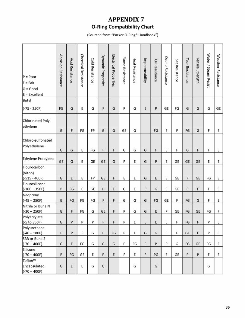
APPENDIX 7 O-Ring Compatibility Chart
(Sourced from “Parker O-Ring® Handbook”)
Ab
rasion
Re
sistance
Acid
Re
sistance
Ch
emical R
esistan
ce
Co
ld R
esistance
Dyn
amic P
rop
erties
Electrical Pro
perti
es
Flame R
esistan
ce
Heat R
esistance
Imp
ermeab
ility
Oil R
esistan
ce
Ozo
ne R
esistance
Set Re
sistance
Tear Resistan
ce
Tensile Stren
gth
Water / Steam
Re
sist
Weath
er Re
sistance
P = Poor
F = Fair
G = Good
E = Excellent
Butyl
(-75 - 250F) FG G E G F G P G E P GE FG G G G GE
Chlorinated Poly-
ethylene
G F FG FP G G GE G FG E F FG G F E
Chloro-sulfonated
Polyethylene
G G E FG F F G G G F E F G F F E
Ethylene Propylene
GE G E GE GE G P E G P E GE GE GE E E
Flourocarbon
(Viton)
(-515 - 400F) G E E FP GE F E E G E E GE F GE FG E
Flourosilicone
(-100 – 350F) P FG E GE P E G E P G E GE P F F E
Neoprene
(-45 – 250F) G FG FG FG F F G G G FG GE F FG G F E
Nitrile or Buna N
(-30 – 250F) G F FG G GE F P G G E P GE FG GE FG F
Polyacrylate
(-5 to 350F) G P P P F F P E E E E F FG F P E
Polyurethane
(-40 – 180F) E P F G E FG P F G G E F GE E P E
SBR or Buna S
(-70 – 400F) G F FG G G G P FG F P P G FG GE FG F
Silicone
(-70 – 400F) P FG GE E P E F E P PG E GE P P F E
Teflon™
Encapsulated G E E G G G G G
(-70 – 400F)

37
APPENDIX 8 Quote Request / Order Form
For CV Series High Pressure Valves
Required Valve Type and Configuration Information.
Customer’s Name _____________________________ Company _____________________________ Address _____________________________ Phone Number _____________________________ Fax Number _____________________________ Email Address _____________________________ Purchase Order Number _________________________
2-Way Valve 3-Way Valve
Select Wetted Material
316 Stainless Steel ________ ________
Hastelloy C-276 ________ ________
Expected Fluid Types
Water (distilled) ________ ________
Brine ________ ________
Mineral Oil ________ ________
Crude Oil ________ ________
(Specify)
Other Oil ________ ________ ________
Solvents ________ ________ ________
Acids ________ ________ ________
Corrosives ________ ________ ________
Polymers ________ ________ ________
Other ________ ________ ________
Expected Operating Temperature
Less than 60ºF (16ºC) ________ ________
If less than 60ºF, how low? ________ ________ ________
Between 60ºF and 150ºF (16º to 65º C) ________ ________
Between 60ºF and 300ºF (16º to 149º C) ________ ________
Greater than 300ºF (149ºC) ________ ________
If greater than 300ºF, how high? ________ ________ ________

38
A
Air Compressor ............................................. 7,24,25 Air Inlet Fittings ...................................................... 8 Air Lines
Numbered or Color Coded Tags ........................ 8 Air Supply
Input and Output ............................................... 7 Requirements .................................................... 7
C
Cone Inspecting ........................................................ 14
Configuration .......................................................... 1 2-Way Valve ...................................................... 5 3-Way Valve ...................................................... 6 Closed / Closed .................................................. 6 Closed / Open .................................................... 6 Open / Closed .................................................... 6 Open / Open ...................................................... 6
D
Dimensions ............................................................. 4
F
Fittings ............................................................... 4,34 Flow Coefficient ...................................................... 3 Flow Direction ........................................................ 5 Fluid Supply Problems .......................................... 24
M
Maintenance ........................................................ 21 Tools ................................................................ 11
Manifolds ............................................................... 7
O
Operation Principles 2-Way Valve ...................................................... 5 3-Way Valve ...................................................... 5
O-Ring Compatibility Chart ......................................... 36 Greasing ................................................ 16,23,35 Seal Material ..................................................... 1 Disassemble ..................................................... 13 Reassemble ..................................................... 15
P
Piston Assembly Diagram .......................................................... 12 Disassemble ..................................................... 13 Reassemble ..................................................... 15
Power Solenoid Pilot Valve ........................................... 8
Pressure Rating ....................................................... 1 Maximum .......................................................... 1
Q
Quote Order Form ...................................................... 37 Request Form .................................................. 37
S
Sleeve Inspecting ........................................................ 14
Sleeve & Cone Assembly Diagram ........................................................... 13
Sleeve Assembly Disassemble ..................................................... 13 Reassemble...................................................... 14
Solenoid Pilot Valve ................................................ 1 Audio Check ..................................................... 22 Connecting ..................................................... 7-9 Visual Check ..................................................... 21
T
Temperature Rating ............................................... 2 Troubleshooting ................................................... 21
V
Valve Closed Valve Diagram ........................................ 5 CV-210 Connection Diagram .......................... 8,9 CV-210 Diagram ............................................... 11 CV-310 Connection Diagram ............................. 9 CV-310 Diagram ............................................... 17 Disassemble 2-Way ......................................... 11 Disassemble 3-Way ......................................... 17 High Temperature ............................................. 9
Connecting Air Lines ..................................... 9 Maintenance ......................................... 11,17,21 Models ............................................................... 3 Open Valve Diagram .......................................... 5 Reassemble 2-Way .......................................... 15 Reassemble 3-Way .......................................... 18 Size .................................................................... 4
Valve-Solenoid Pilot See Solenoid Pilot Valve .................................... 7
Volume Internal .............................................................. 3
W
Wetted Parts ........................................................... 2