Embed Size (px)
Citation preview

84504 State Hwy 11, Burwell, Nebraska 68823Phone: 308-348-2276 • Fax: 308-348-2059
Toll-Free: 800-652-1912Website: www.rowserakes.com • E-Mail: [email protected]
V-RAKE
OPERATOR'S MANUAL& PARTS LIST

Revised May 2016
LIPS Printing Service · Kearney, NE

ROWSE HYDRAULIC RAKES CO., INC84504 State Hwy 11, Burwell, Nebraska 68823
Phone: 308-348-2276 Fax: 308-348-2059Toll-Free: 800-652-1912
E-mail: [email protected]
Website: www.rowserakes.com
CONTENTS SUMMARY
SECTION
A Introduction A
B Assembly Instructions B
C Operating Instructions C
D Safety D
E Service E
F Troubleshooting F
G Parts List G
H Index H
1

2
Section A: introduction
5 To The Owner 5 General Outline Of This Manual 6 V-Rake Models Discussed 6 Location of Model Number And Serial Number of Your Rowse V-Rake 7 TireInflationPressures 7 Bolt Torque Information 8 Safety and Special Information 8 Limited Warranty 9 Warranty Detail
Section B: ASSemBly inStructionS
11 Introduction 13 Main Frame 14 Rear Frame16 RearPivot 17 Lift Cylinder 18 Flex Hinge 19 Front Wing and Caster Wheel20 PositioningArm 22 Raking Wheel and Compression Spring 24 Optional Kicker Wheel 26 Hydraulic Hookup27 HydraulicValveControlBox(Optional) 28 Assembled View
Section c: operAting inStructionS
29 Introduction 29 Operating Safety 30 Hydraulic Operating Notes 30 Bleeding the Air from the Hydraulic Lines 31 Adjusting Raking Wheel Weight 32 Windrow Width 33 Raking Wheel Angle 33 Operating Notes 34 Transporting36 KickerWheels(Optional) 38 Rough Terrain Dual Wheel Assembly 38 Feature Descriptions
Section d: SAfety
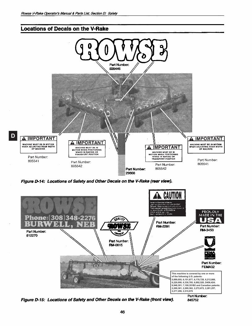
41 Safety and Special Information 41 Operating Safety 43 Safety Decals 44 Close-Ups of Safety Decals 44 Close-Ups of Other Decals 45 Locations of Decals on the V-Rake
(Continued on next page)

Section e: Service
47 Safety Reminders 47 Tighten Bolts 48 Lubrication, Introduction 49 Rear Frame Lubrication 50 Main Frame Lubrication51 V-Arm(Wing)Lubrication 53 Kicker Wheels Lubrication 54 Storage
Section f: trouBleShooting
55 Introduction55 ServiceSafety55 ServiceChecklist 56 Troubleshooting Guide
Section g: pArtS liSt
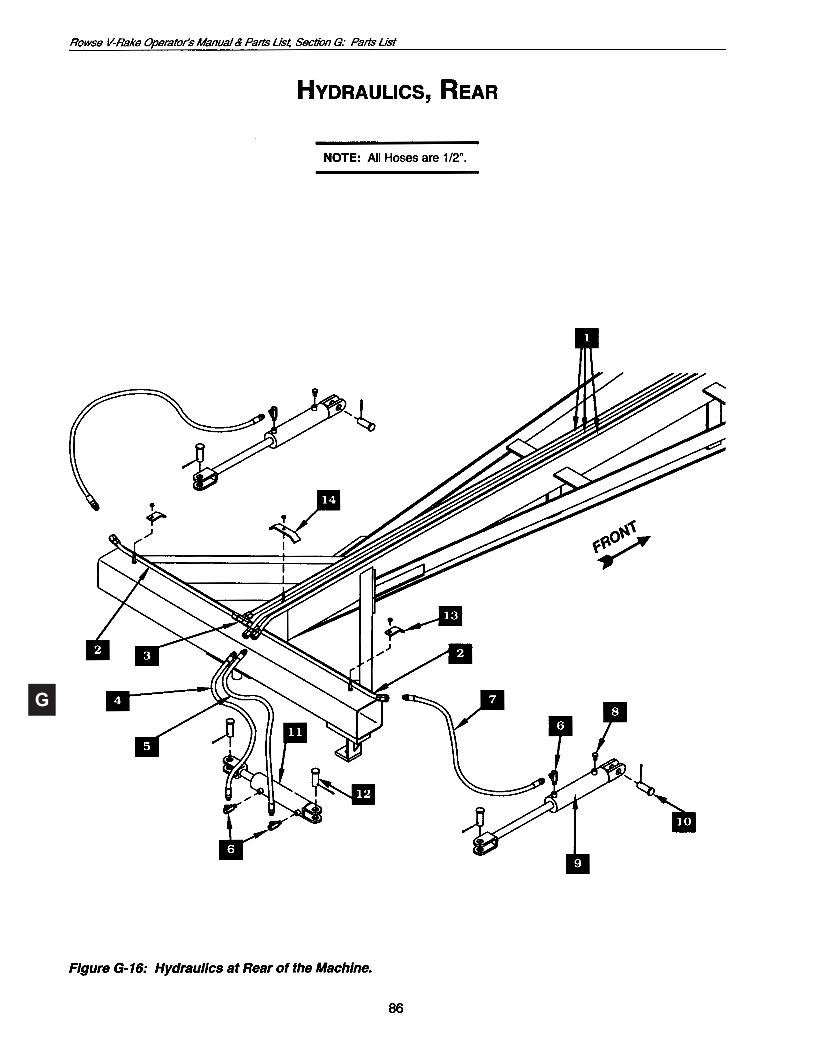
59 Introduction 59 Decals59 OverallPartsGroups 60 Main Frame, Tongue, Extension62 PositioningArm 64 Rear Frame 66 Hub / Wheel Assembly68 RearPivotandCompressionSpring 70 Flex Hinge and Wing 72 Front Wing and Castor 74 Raking Wheel 76 Kicker Wheel, Opposing Wheel Style (fortwo-way,splitdischarge) 78 Kicker Wheel, Tandem Wheel Style (forone-waydischarge) 80 Kicker Wheel, Tine Wheel 82 Hydraulics, Front 84 Hydraulics, Middle 86 Hydraulics, RearHydraulic Cylinders: Large(Left)Master/SlaveCylinder 88 For Serial Number JJ and Newer 89ForPriortoSerialNumberJJ Small(Right)Master/SlaveCylinder 90 For Serial Number JJ and Newer 91ForPriortoSerialNumberJJ 92 Lift Cylinder 93 Widener Cylinder 94 Kicker Wheel Cylinder
Section h: index
95 Subject Index

A
A
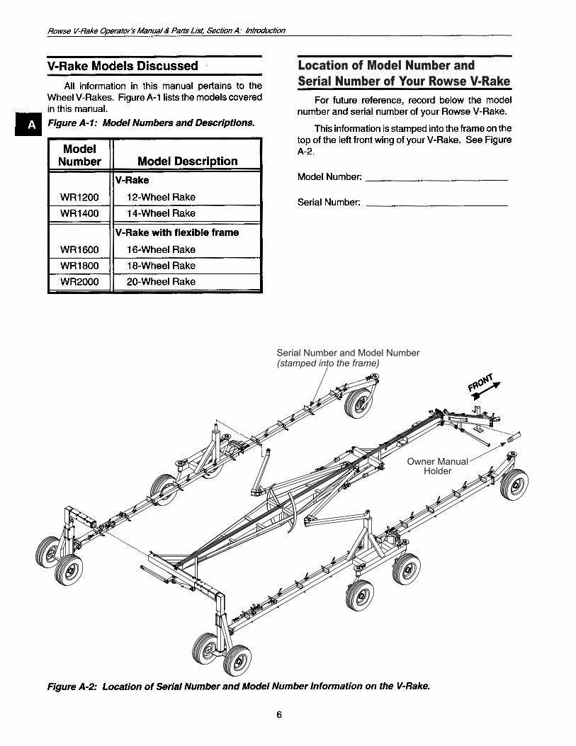
Location of Model Number andSerial Number of Your Rowse V-Rake
Serial Number and Model Number(stamped into the frame)
Owner ManualHolder

A
7
A
8
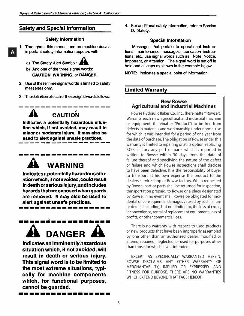
New Rowse Agricultural and Industrial Machines Rowse Hydraulic Rakes Co., Inc., (hereinafter “Rowse”).
Warrants each new agricultural and indus trial machine or equipment, (hereinafter “Product”) to be free from defects in materials and workmanship under normal use for which it was intended for a pe riod of one year from the date of purchase. The obli gation of Rowse under this warranty is limited to re pairing or at its option, replacing F.O.B. factory any part or parts which is reported in writing to Rowse within 30 days from the date of failure thereof and specifying the nature of the defect or failure and which Rowse inspections shall disclose to have been defec tive. It is the responsibility of buyer to transport at his own expense the product to the dealers service shop or Rowse factory. When requested by Rowse, part or parts shall be returned for inspection, transpor tation prepaid, to Rowse or a place designated by Rowse. In no event shall Rowse be obligated for incidental or consequential damages caused by such fail ure or defect, including, but not limited to, the loss of crops, inconvenience, rental of replacement equip ment, loss of profits, or other commercial loss.
There is no warranty with respect to used products or new products that have been improperly assembled by one other than an authorized dealer, modified or altered, repaired, neglected, or used for purposes other than those for which it was intended.
EXCEPT AS SPECIFICALLY WARRANTED HEREIN, ROWSE DISCLAIMS ANY OTHER WARRANTY OF MERCHANTABILITY, IMPLIED OR EXPRESSED, AND FITNESS FOR PURPOSE. THERE ARE NO WARRANTIES WHICH EXTEND BEYOND THAT FACE HEREOF.
A
9
1. Tires shall be warranted by the selling dealer or bylocalrepresentativesofthetiremanufacturer.

10

B
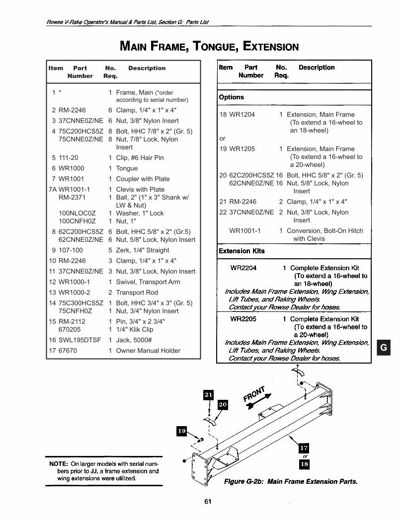
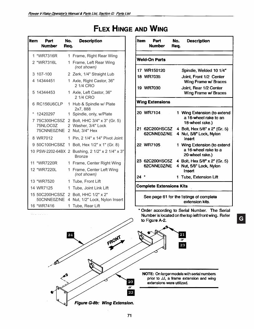
NOTE: On larger models with serial numbers prior to JJ, a frame extension and wing extensions were utilized.
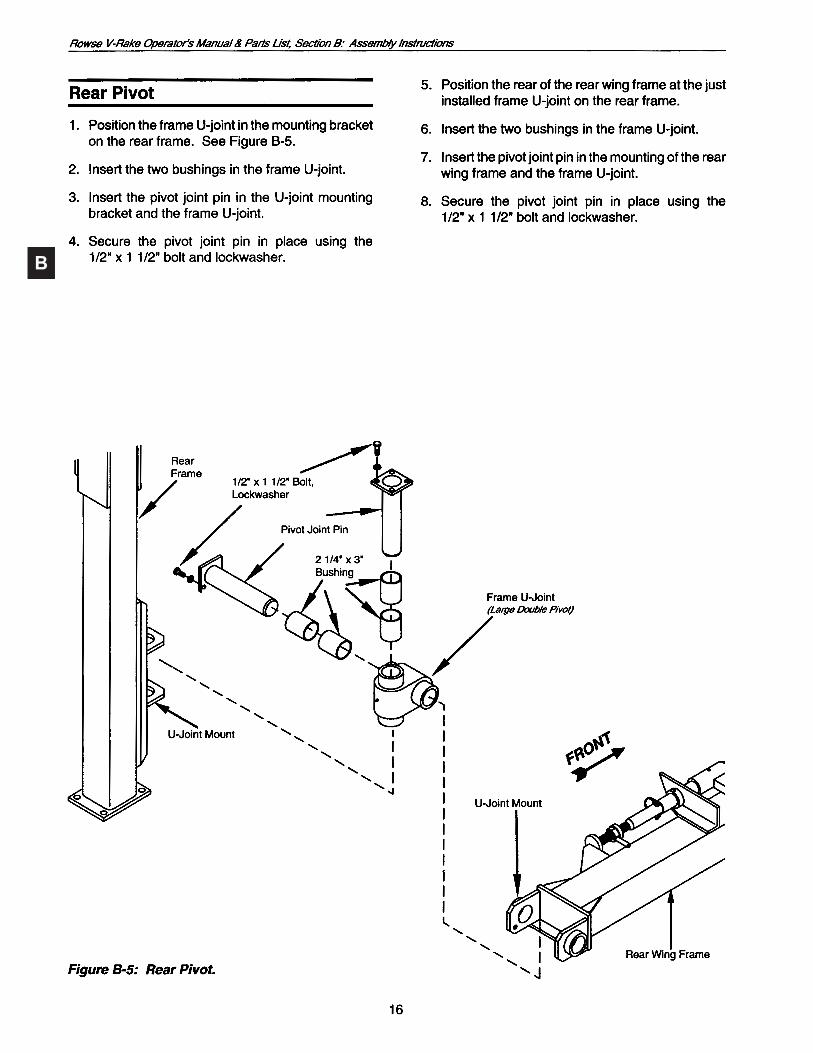
Main Frame
Rear Frame
Rear Wheels
Rear Pivot
Rear Wing
FlexHinge
CenterWheels
CenterWing
FrontWheel
FrontWing
RakingWheel
Tongue
PositioningArm

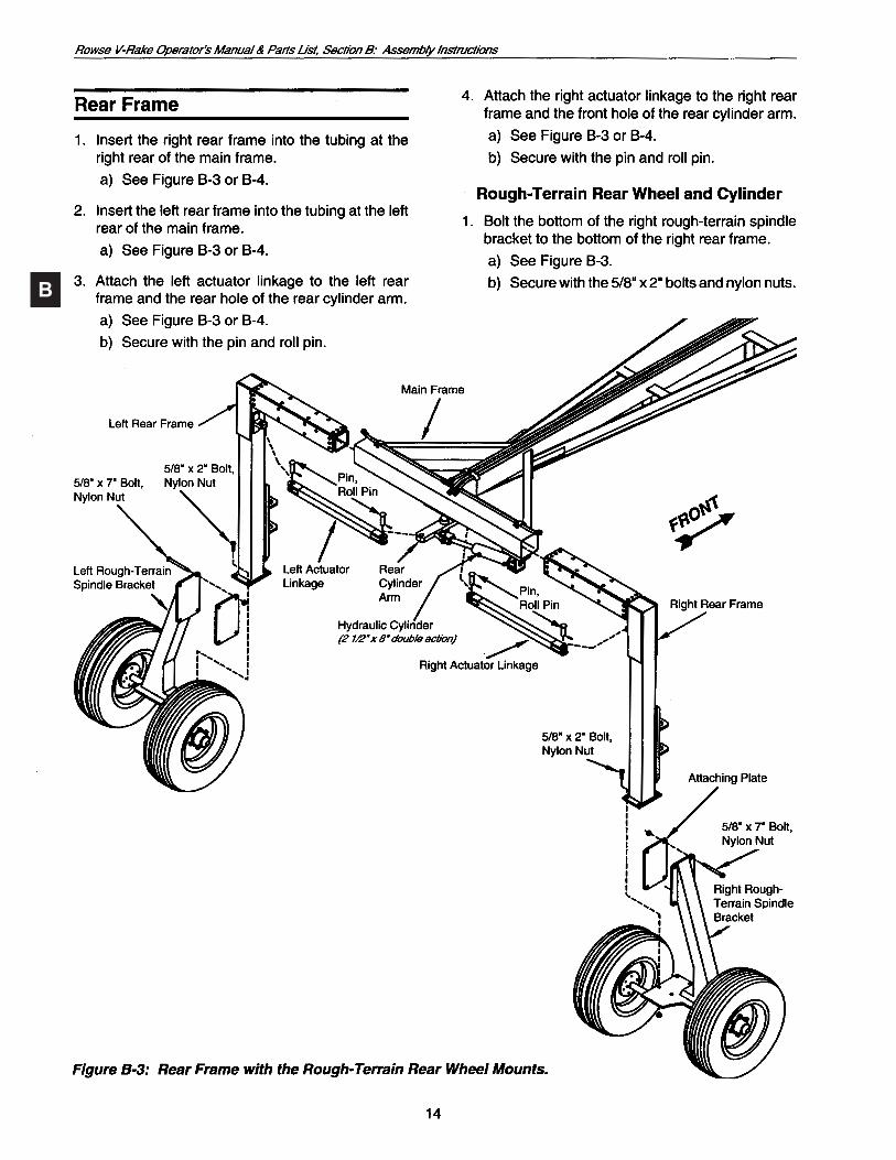
BMain Frame
Rear Frame
Rear Wheels
Rear Pivot
Rear Wing
FrontWheel
FrontWing
RakingWheel
Tongue
PositioningArm
B
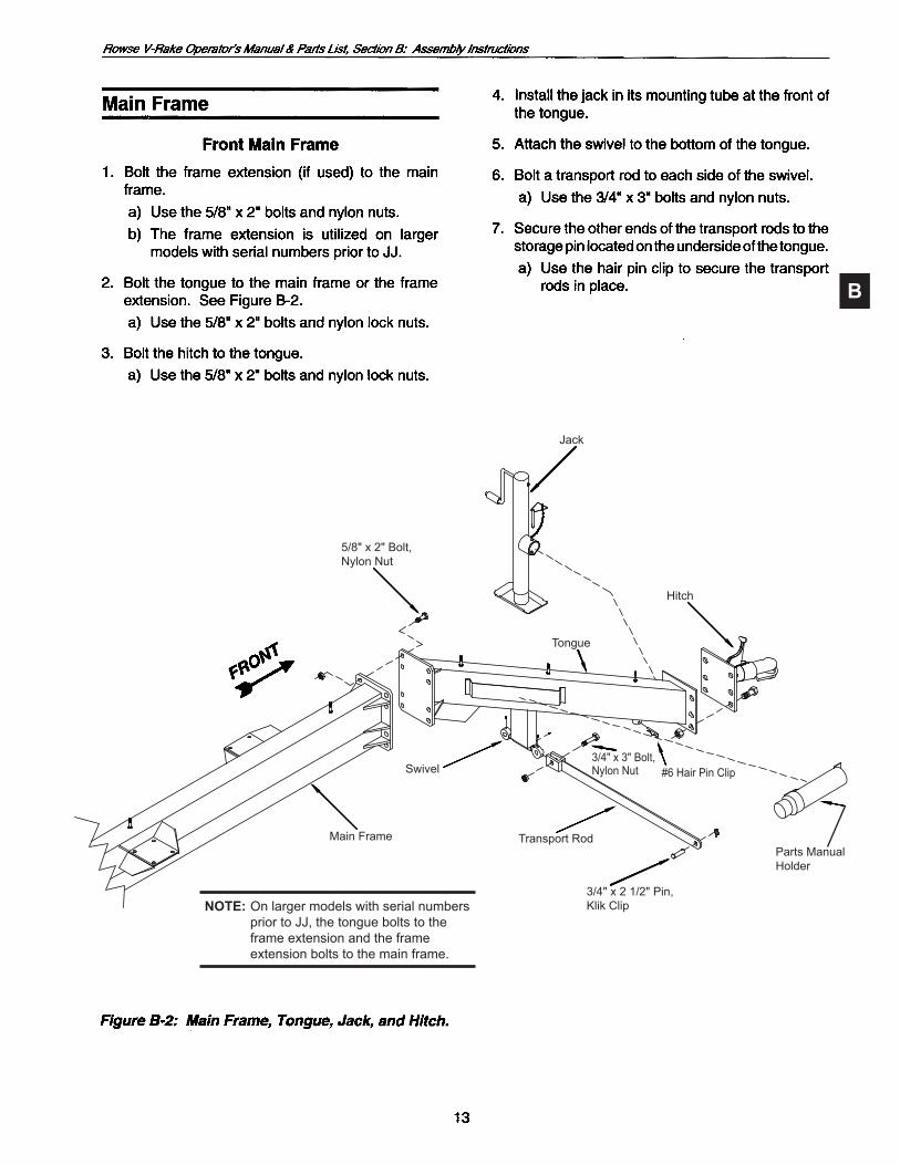
Main Frame
Swivel
Transport Rod
3/4"x21/2"Pin,Klik Clip
3/4" x 3" Bolt,Nylon Nut #6HairPinClip
Tongue
Hitch
Jack
5/8" x 2" Bolt,Nylon Nut
PartsManualHolder
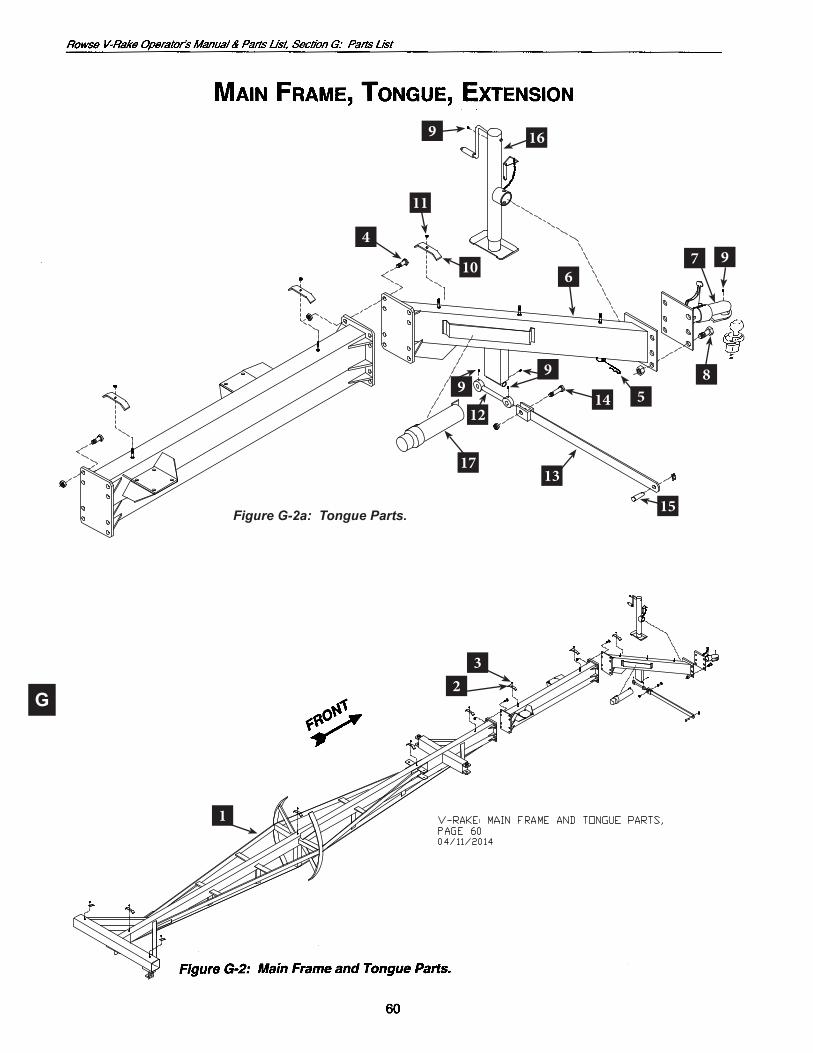
NOTE: On larger models with serial numbers prior to JJ, the tongue bolts to the frame extension and the frame extension bolts to the main frame.
B
B
B
B
B
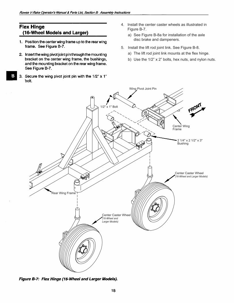
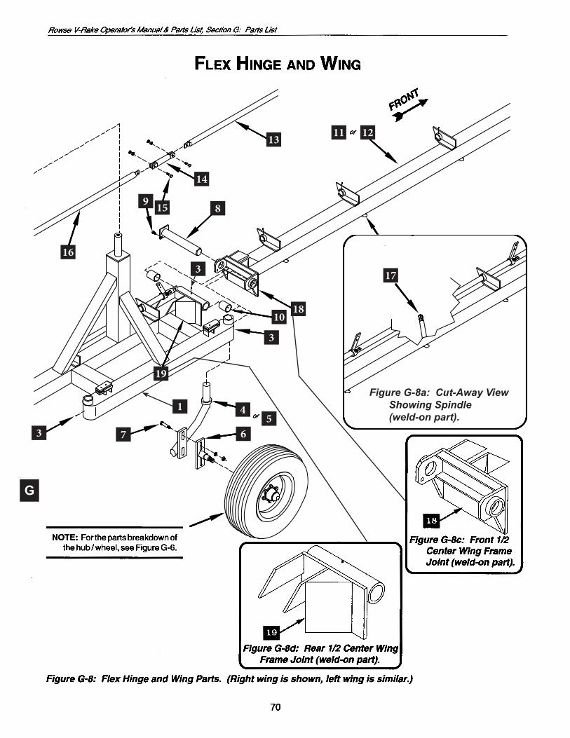
4. Install the center caster wheels as illustrated in Figure B-7.
a) SeeFigureB-8aforinstallationoftheaxle disc brake and dampeners.
5. Install the lift rod joint link. See Figure B-8. a) Theliftrodjointlinkmountsattheflexhinge. b) Usethe1/2”x2”bolts,hexnuts,andnylonnuts.
1/2" x 1" Bolt
WingPivotJointPin
Center Wing Frame
2 1/4" x 2 1/2" x 3" Bushing
Center Caster Wheel(16-Wheel and Larger Models)
Rear Wing Frame
Center Caster Wheel(16-Wheel andLarger Models)
B
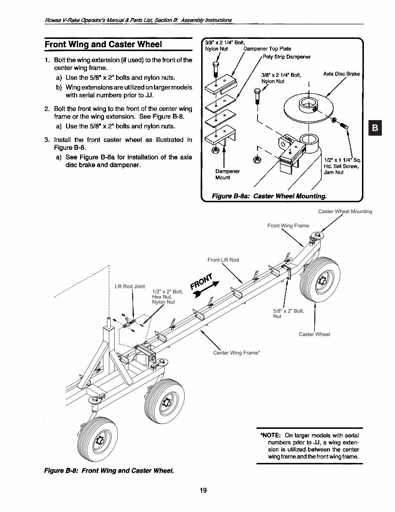
Caster Wheel Mounting
Caster Wheel
5/8" x 2" Bolt,Nut
Center Wing Frame*
Front Wing Frame
Front Lift Rod
Lift Rod Joint1/2" x 2" Bolt,Hex Nut,Nylon Nut

B
Figure B-9
LeftPositioningArmCylinder(LargeMaster/SlaveCylinder)
(23/4"x15")
Main Frame
Bushing
HingePin,CoverPlate,Nut
PositioningArmU-Joint(Small Double Pivot)
OuterPositioningArm
Rear Wing Frame
Spindle
Bushing
CoverPlate3/4" x 2" Bolt, Lockwasher
InnerPositioningArm
HingePin,CoverPlate,Nut
1"x27/8"HeadedPin,3/16" x 2" Cotter KeyPin,RollPin
PositioningArmCylinderMount
RightPositioningArmCylinder(SmallMaster/SlaveCylinder)(2 1/4" x 15")
1"x27/8"HeadedPin,3/16" x 2" Cotter Key
PositioningArmCylinderLinkage
PositioningArmCylinderMount
Pin,RollPinBushing
PositioningArmU-Joint(Small Double Point)

B
LeftPositioningArmCylinder(LargeMaster/SlaveCylinder)(23/4"x15")
RightPositioningArmCylinder(SmallMaster/SlaveCylinder)(2 1/4" x 15")
B
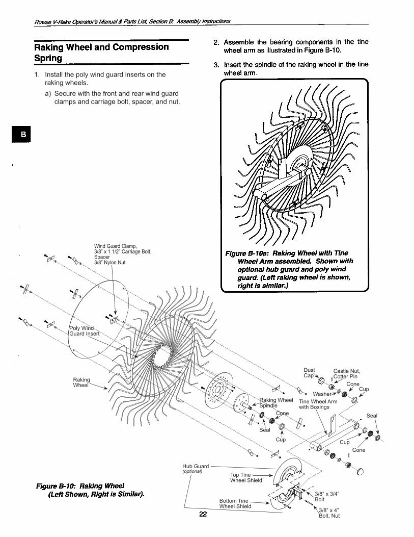
Tine Wheel Armwith Boxings
ConeCup
Seal
DustCap
Castle Nut,CotterPin
ConeCup
Washer
Cone
Seal
Cup
Raking Wheel Spindle
Wind Guard Clamp,3/8”x11/2”CarriageBolt,Spacer3/8”NylonNut
PolyWindGuard Insert
RakingWheel
1. Install the poly wind guard inserts on the raking wheels. a) Securewiththefrontandrearwindguard clamps and carriage bolt, spacer, and nut.
Hub Guard(optional)
Top TineWheel Shield
Bottom TineWheel Shield
3/8”x3/4”Bolt
3/8”x4”Bolt, Nut
B
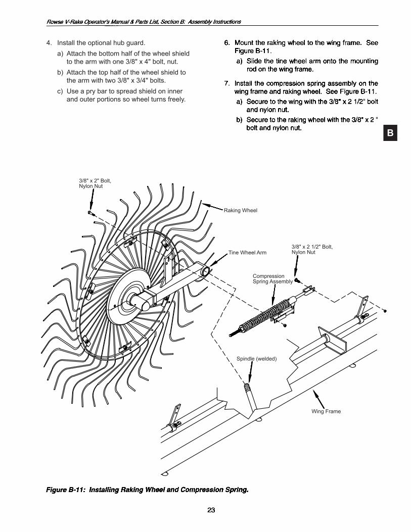
3/8" x 2" Bolt,Nylon Nut
Raking Wheel
Tine Wheel Arm3/8" x 2 1/2" Bolt,Nylon Nut
CompressionSpring Assembly
Spindle(welded)
Wing Frame
4. Install the optional hub guard. a) Attachthebottomhalfofthewheelshield to the arm with one 3/8" x 4" bolt, nut. b) Attachthetophalfofthewheelshieldto the arm with two 3/8" x 3/4" bolts. c) Useaprybartospreadshieldoninner and outer portions so wheel turns freely.
B
B
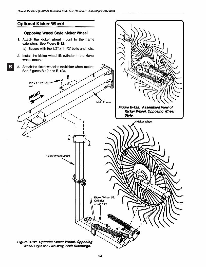
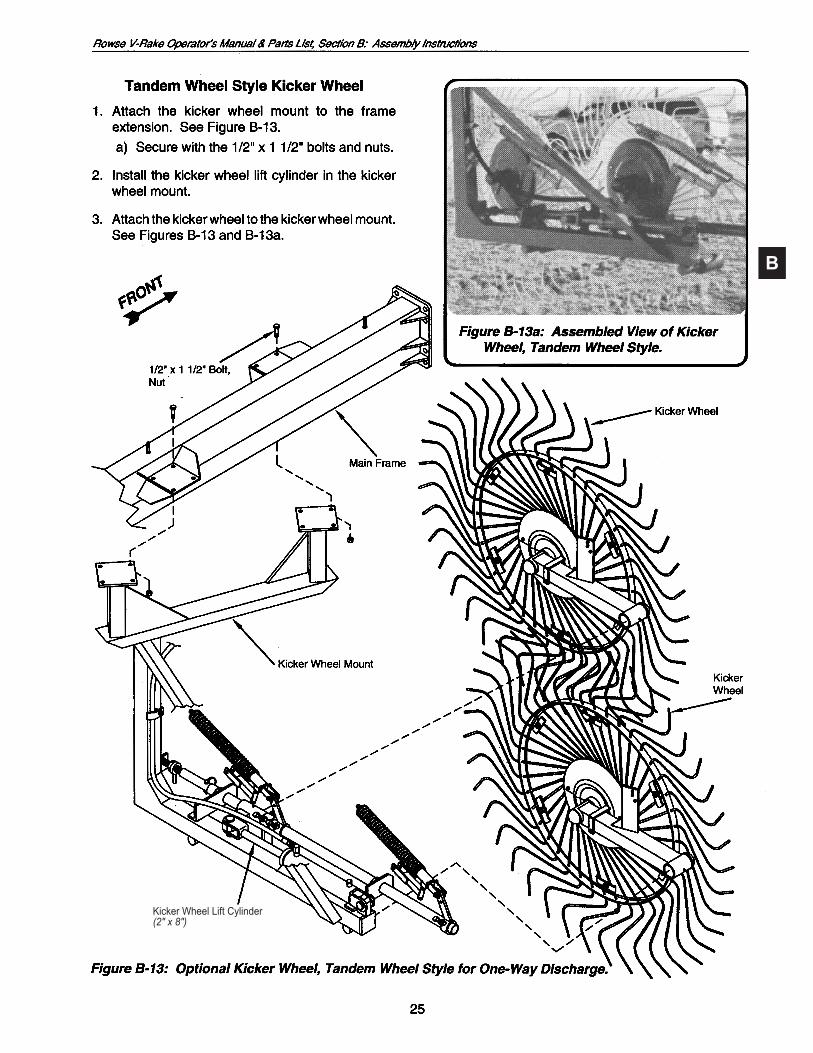
Kicker Wheel Lift Cylinder(2" x 8")
B
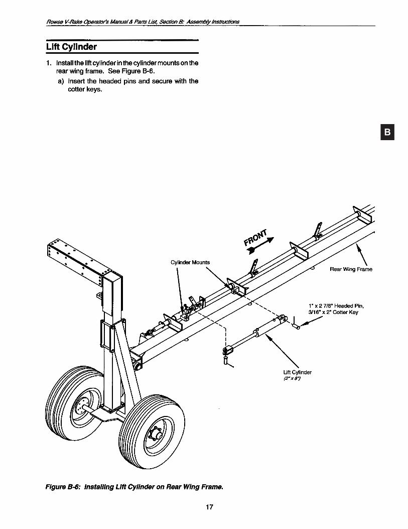
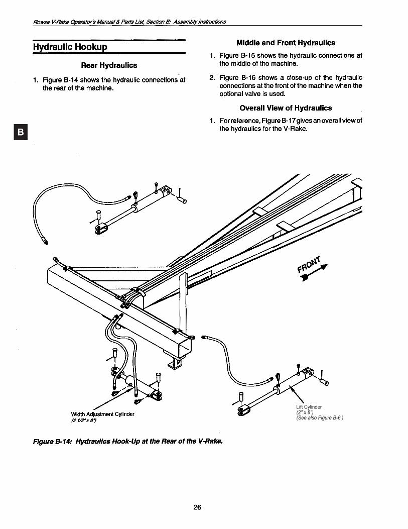
Lift Cylinder(2" x 8")(See also Figure B-6.)

B
Kicker Wheel Cylinder
RightPositioningArmCylinder(2 1/4" x 15")
LeftPositioningArm Cylinder(2 3/4" x 15")
Valve(Optional)
Control CableControl Box

B PositioningArm Cylinder
Lift Cylinder
Lift Cylinder
PositioningArm Cylinder
Kicker Wheel Cylinder(optional)
AB CC
AA B CC
A
A - WingB - LiftC - Widener

C
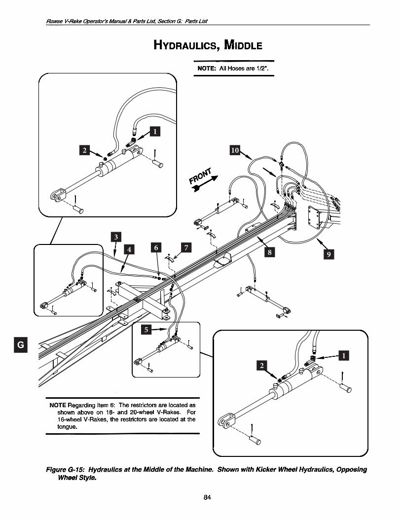
C c) Onedouble-actingvalvetoadjustrearframe windrow width.
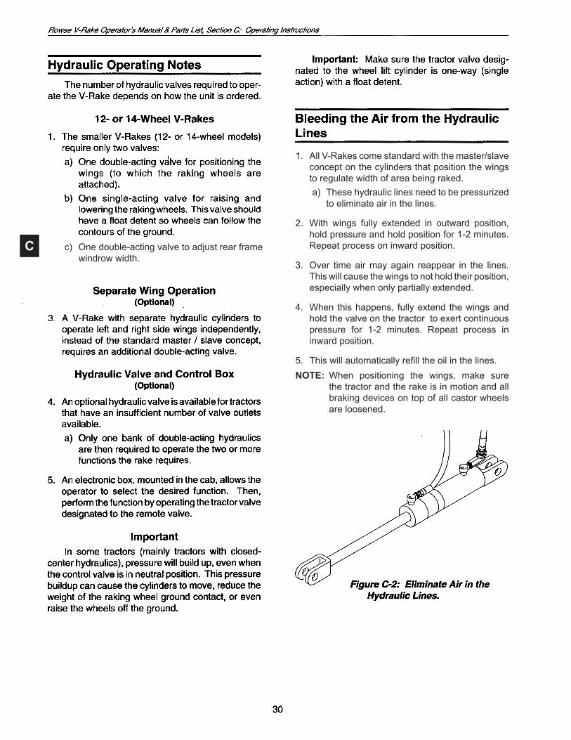
1. AllV-Rakescomestandardwiththemaster/slaveconcept on the cylinders that position the wings to regulate width of area being raked.
a) Thesehydrauliclinesneedtobepressurizedto eliminate air in the lines.
2. With wings fully extended in outward position, hold pressure and hold position for 1-2 minutes. Repeat process on inward position.
3. Over timeairmayagain reappear in the lines.This will cause the wings to not hold their position, especially when only partially extended.
4. When this happens, fully extend the wings and holdthevalveonthetractortoexertcontinuouspressure for 1-2 minutes. Repeat process in inward position.
5. Thiswillautomaticallyrefilltheoilinthelines.NOTE: When positioning the wings, make sure
the tractor and the rake is in motion and all brakingdevicesontopofallcastorwheelsare loosened.
C
1. Starter setting: raking wheels should be set so that they produce 25 pounds of ground contact weight.
a) Useabathroomscaleorfishscaletocheckweights to approximately 25 pounds.
b) Make sure all compression springs arelubricated before adjusting weight.
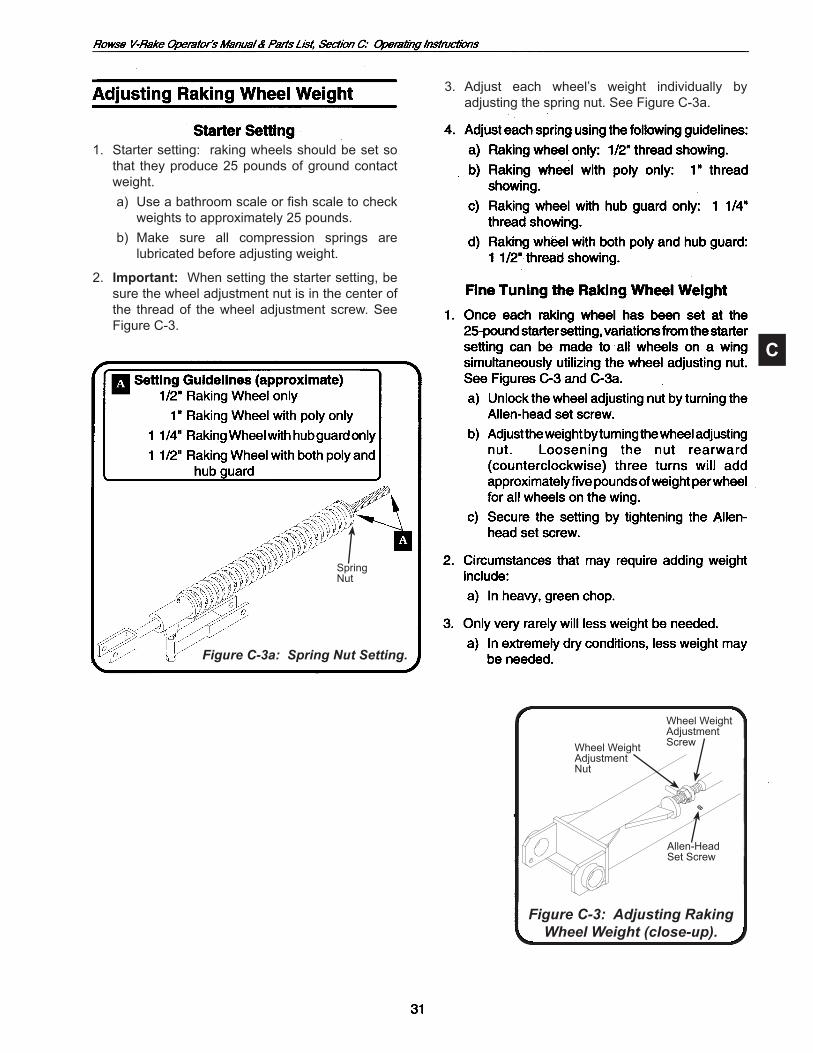
2. Important: When setting the starter setting, be sure the wheel adjustment nut is in the center of the thread of the wheel adjustment screw. See Figure C-3.
3. Adjust each wheel’s weight individually byadjusting the spring nut. See Figure C-3a.
Figure C-3: Adjusting RakingWheel Weight (close-up).
Wheel WeightAdjustmentScrewWheel Weight
AdjustmentNut
Allen-HeadSet Screw
Spring Nut
Figure C-3a: Spring Nut Setting.
SpringNut

C

C
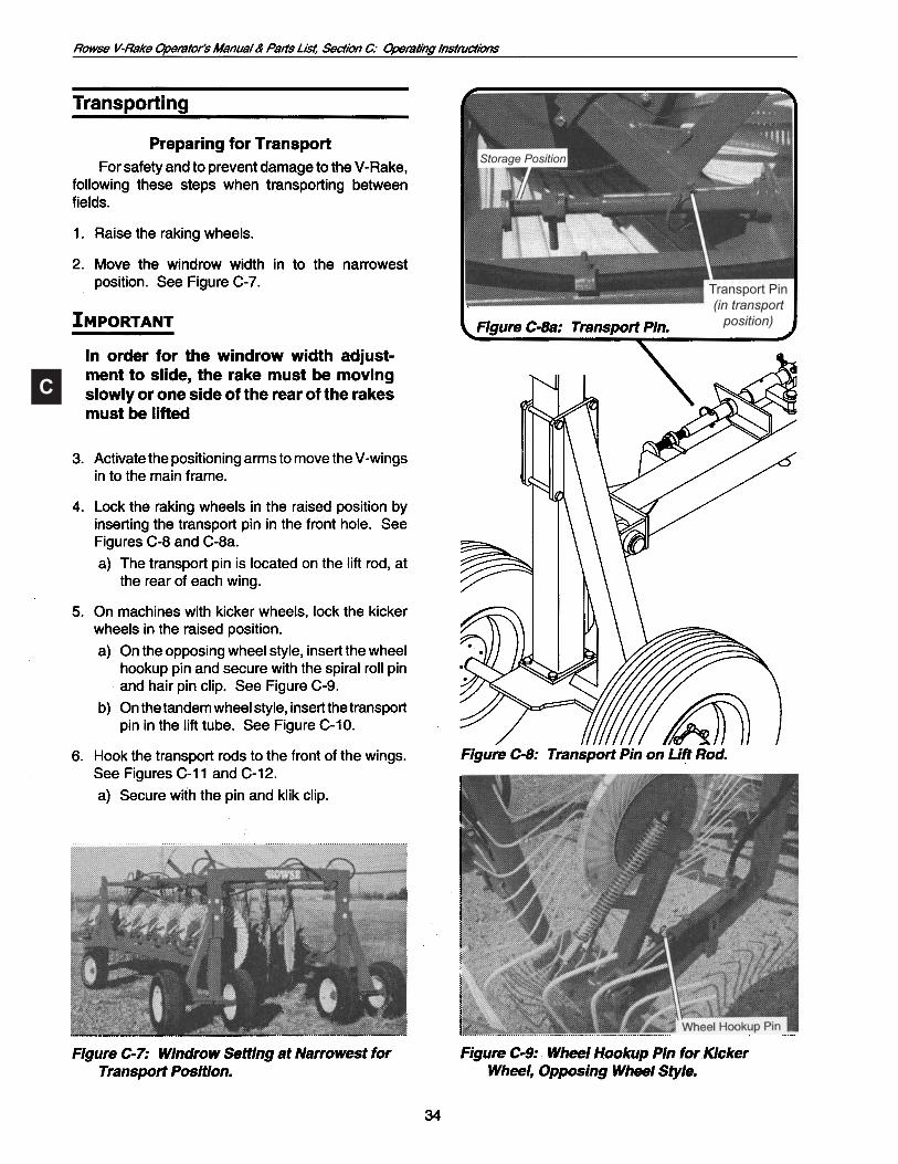
TransportPin(in transport
position)
Storage Position
C

C
3/4"x21/2"Pin,Klik Clip

C
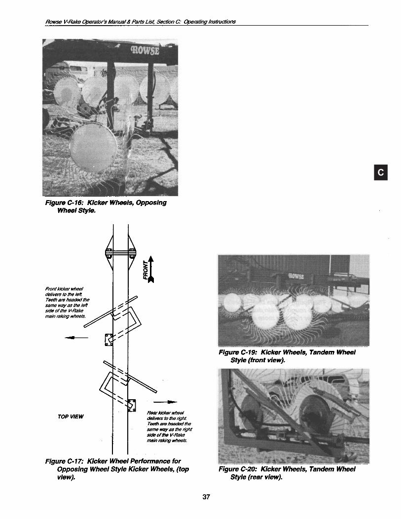
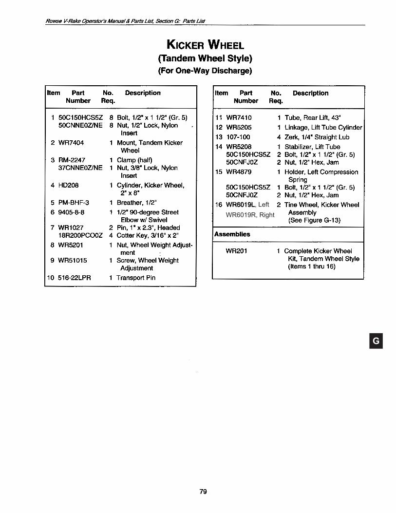
2. Thetandemkickerwheelsaresetatafixed 45° angle.
C
C
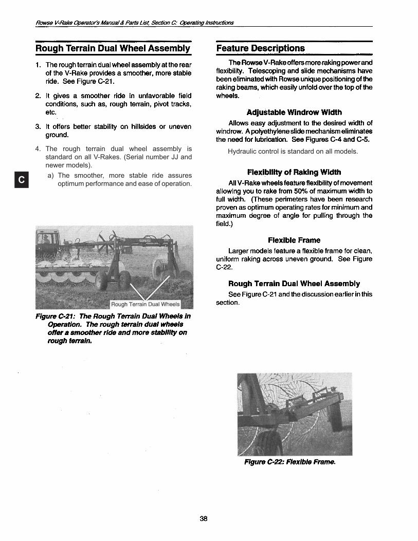
Hydraulic control is standard on all models.4. The rough terrain dual wheel assembly is standardonallV-Rakes.(SerialnumberJJandnewermodels).
a) The smoother, more stable ride assuresoptimum performance and ease of operation.
C
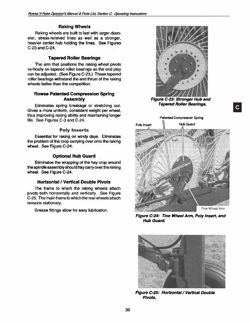
Poly Inserts
C
D
D
D
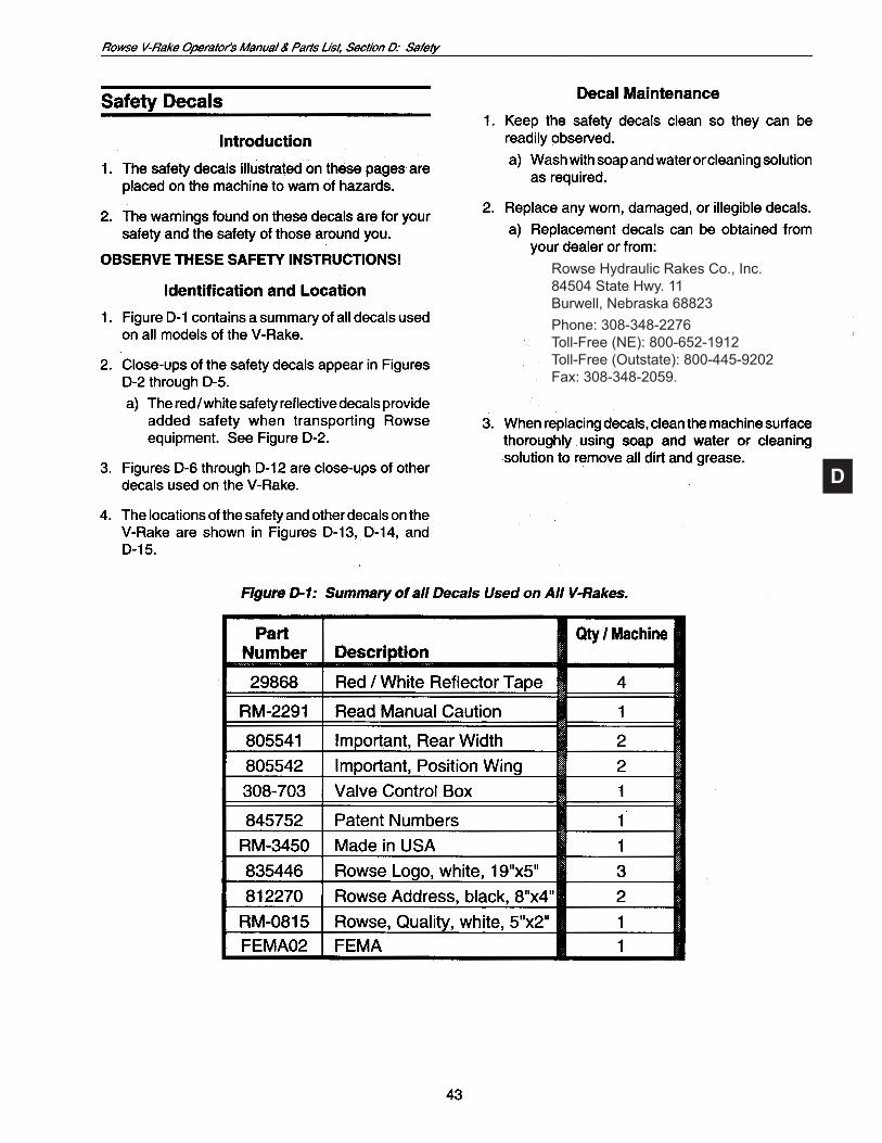
Rowse Hydraulic Rakes Co., Inc.84504 State Hwy. 11Burwell, Nebraska 68823Phone:308-348-2276Toll-Free(NE):800-652-1912Toll-Free(Outstate):800-445-9202Fax: 308-348-2059.

D
This machine is covered by one or moreof the following U.S. patents:5,899,055, 6,151,877, 6,178,728, 6,212,866, 6,220,008, 6,330,785, 6,892,520, D456,424; 6,948,301; 7,100,351B2 and Canadian patents: 2,269,361, 2,269,362, 2,272,672, 2,281,257, 2,277,299, 2,515,979
D
D
This machine is covered by one or moreof the following U.S. patents:5,899,055, 6,151,877, 6,178,728, 6,212,866, 6,220,008, 6,330,785, 6,892,520, D456,424; 6,948,301; 7,100,351B2 and Canadian patents: 2,269,361, 2,269,362, 2,272,672, 2,281,257, 2,277,299, 2,515,979
E

E
See Figure E-2
See Figure E-3
See Figure E-8
See Figure E-5
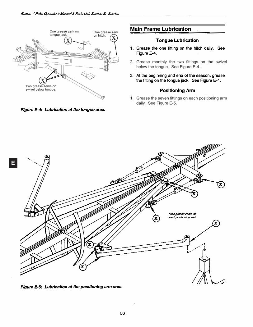
See Figure E-4
See Figure E-7
SeeFigure
E-6

E
1. Greasetheonefittingperrearwheelevery500hours. See Figure E-3.
a) Oneoneachwheelhub. b) Total of 4 rear wheel grease fittings per
machine. See Figure E-3.
1. Grease thefittingsat the rear lift rodassemblydaily. See Figure E-3.
a) Onefittingperwing;totaloftwofittingspermachine.
Grease zerk at rear of lift rod assembly.
E
Two grease zerks onswivelbelowtongue.
X
X
One grease zerk ontongue jack.
XOne grease zerkon hitch.
2. Grease monthly the two fittings on the swivelbelow the tongue. See Figure E-4.
1. Greasethesevenfittingsoneachpositioningarmdaily. See Figure E-5.

E
See Figure E-3.
E
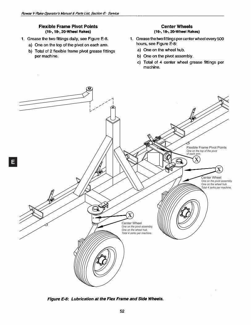
Center WheelOne on the pivot assembly.One on the wheel hub.Total 4 zerks per machine.
X
Center WheelOne on the pivot assembly.One on the wheel hub.Total 4 zerks per machine.
X
FlexibleFramePivotPointsOne on the top of the pivotof each arm.
X
E
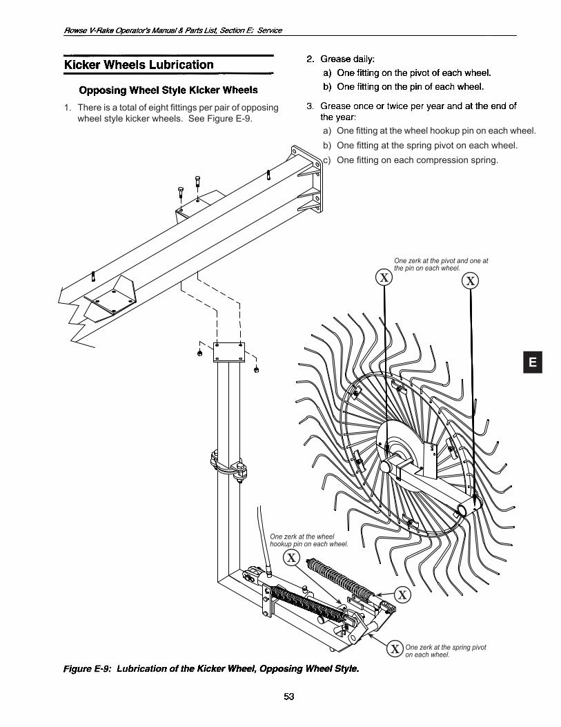
One zerk at the wheelhookup pin on each wheel
One zerk at the pivot and one atthe pin on each wheel.
X X
One zerk at the spring pivoton each wheel.X
One zerk at the wheelhookup pin on each wheel.
X
X
1. Thereisatotalofeightfittingsperpairofopposingwheel style kicker wheels. See Figure E-9.
a) Onefittingatthewheelhookuppinoneachwheel.b) Onefittingatthespringpivotoneachwheel.c) Onefittingoneachcompressionspring.
E
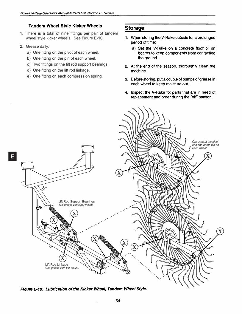
1. There is a total of nine fittings per pair of tandemwheel style kicker wheels. See Figure E-10.
2. Grease daily: a) Onefittingonthepivotofeachwheel. b) Onefittingonthepinofeachwheel. c) Twofittingsontheliftrodsupportbearings. d) Onefittingontheliftrodlinkage. e) Onefittingoneachcompressionspring.
One zerk at the pivotand one at the pin oneach wheel.
X
X
X
XX
X
X
XX
Lift Rod Support BearingsTwo grease zerks per mount.
Lift Rod LinkageOne grease zerk per mount.

F
F
5. Lubricate compression spring slide E-10, page 54.
3. Lubricate compression spring slide E-10, page 54.
F
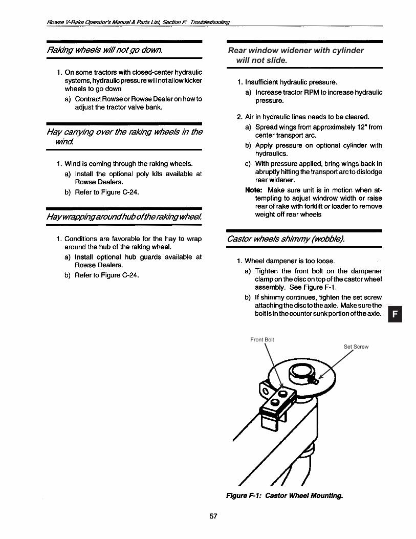
Rear window widener with cylinder will not slide.
Set ScrewFront Bolt

F
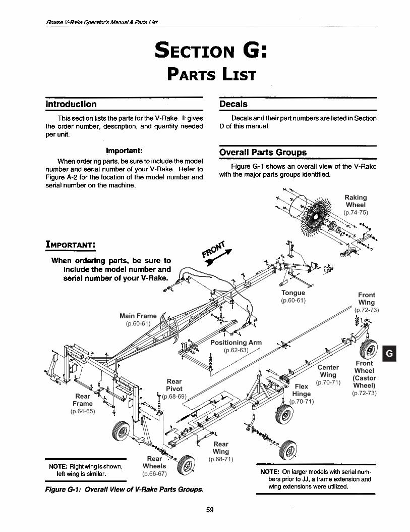
G
RakingWheel(p.74-75)
Tongue(p.60-61)
FrontWing
(p.72-73)
FrontWheel
(CastorWheel)(p.72-73)
CenterWing
(p.70-71)FlexHinge(p.70-71)
RearWing
(p.68-71)RearWheels(p.66-67)
RearFrame(p.64-65)
RearPivot
(p.68-69)
Main Frame(p.60-61)
Positioning Arm(p.62-63)
G
Figure G-2a: Tongue Parts.
9 16
11
10
4
697
89
14
15
13
12
9
17
32
1
5
G
18 WR1204 1 Extension, Main Frame (Toextenda16-wheelto an18-wheel)or19 WR1205 1 Extension, Main Frame (Toextenda16-wheelto a20-wheel)2062C200HCS5Z16 Bolt,HHC5/8"x2"(Gr.5) 62CNNE0Z/NE 16 Nut, 5/8" Lock, Nylon Insert21 RM-2246 2 Clamp, 1/4" x 1" x 4"22 37CNNE0Z/NE 2 Nut, 3/8" Lock, Nylon Insert WR1001-1 1 Conversion,Bolt-OnHitch withClevis
1 * 1 Frame, Main (*order accordingtoserialnumber)
2 RM-2246 6 Clamp, 1/4" x 1" x 4" 3 37CNNE0Z/NE 6 Nut, 3/8" Nylon Insert 4 75C200HCS5Z 8 Bolt,HHC7/8"x2"(Gr.5) 75CNNE0Z/NE 8 Nut, 7/8" Lock, Nylon Insert 5 111-20 1 Clip,#6HairPin 6 WR1000 1 Tongue 7WR1001 1 CouplerwithPlate7AWR1001-1 1 CleviswithPlate RM-2371 1 Ball,2"(1"x3"Shankw/ LW&Nut) 100NLOC0Z 1 Washer, 1" Lock 100CNFH0Z 1 Nut, 1" 8 62C200HCS5Z 6 Bolt,HHC5/8"x2"(Gr.5) 62CNNE0Z/NE 6 Nut, 5/8" Lock, Nylon Insert 9 107-100 5 Zerk, 1/4" Straight10 RM-2246 3 Clamp, 1/4" x 1" x 4"11 37CNNE0Z/NE 3 Nut, 3/8" Lock, Nylon Insert12WR1000-1 1 Swivel,TransportArm13 WR1000-2 2 Transport Rod1475C300HCS5Z 1 Bolt,HHC3/4"x3"(Gr.5) 75CNFH0Z 1 Nut, 3/4" Nylon Insert15RM-2112 1 Pin,3/4"x23/4" 670205 1 1/4" Klik Clip16 SWL195DTSF 1 Jack, 5000#17 67670 1 Owner Manual Holder
Item Part No. Description Number Req.
G
G
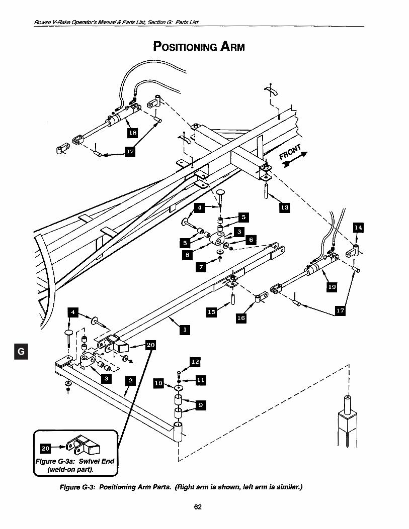
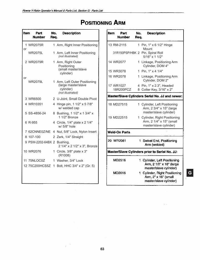
1WR2075R 1 Arm,RightInnerPositioningor WR2075L 1 Arm,LeftInnerPositioning (not illustrated)
2 WR2079R 1 Arm, Right Outer Positioning (smallmaster/slave cylinder)or WR2079L 1 Arm,LeftOuterPositioning (largemaster/slave cylinder) (not illustrated)
3WR6500 2 U-Joint,SmallDoublePivot 4 WR10351 4 Hinge pin, 1 1/2" x 5 7/8" w/ welded cap 5 SS-4856-24 8 Bushing, 1 1/2" x 1 3/4" x 1 1/2" Bronze 6 R-955 4 Circle, 1/4" plate x 2 1/4" w/ 5/8" hole 7 62CNNE0Z/NE 4 Nut, 5/8" Lock, Nylon Insert 8 107-100 2 Zerk, 1/4" Straight 9 PSW-2202-64BX 2 Bushing, 2 1/4" x 2 1/2" x 3", Bronze10 WR2076 1 Circle, 3/8" plate x 3" (R1008)11 75NLOC0Z 1 Washer, 3/4" Lock1275C200HCS5Z 1 Bolt,HHC3/4"x2"(Gr.5)
13RM-2115 1 Pin,1"x61/2"Hinge Mount 31R150PSP/HBK2 Pin,SpiralRoll 5/16" x 1 1/2"14WR2077 1 Linkage,PositioningArm Cylinder, DOM 4"15WR3078 1 Pin,1"x41/4"16WR2078 1 Linkage,PositioningArm Cylinder, DOM 2"17WR1027 4 Pin,1"x2.3",Headed 18R200PCZ 8 CotterKey,3/16"x2"
18MD27515 1 Cylinder,LeftPositioning Arm,23/4"x15"(large master/slavecylinder)19MD22515 1 Cylinder,RightPositioning Arm,21/4"x15"(small master/slavecylinder)

G
27
25
26
G
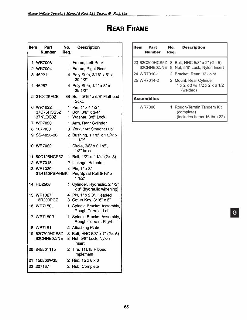
2362C200HCS5Z 8 Bolt,HHC5/8"x2"(Gr.5) 62CNNE0Z/NE 8 Nut, 5/8" Lock, Nylon Insert24 WR7010-1 2 Bracket, Rear 1/2 Joint25 WR7014-2 2 Mount, Rear Cylinder 1 x 2 x 3 w/ 1/2 x 2 x 6 1/2 (welded)
Assemblies
WR7006 1 Rough-Terrain Tandem Kit (complete) (includesItems16thru22)
18R200PCZ
Item Part No. Description Number Req.
4
4
G

G
2 845502258 1 Tire,SR225/75R15(front andside)8ply
G
10
11
12
1
24
35
2726
25
21
20
22
2324
18
19
1617
28
158
6
7
929
1413
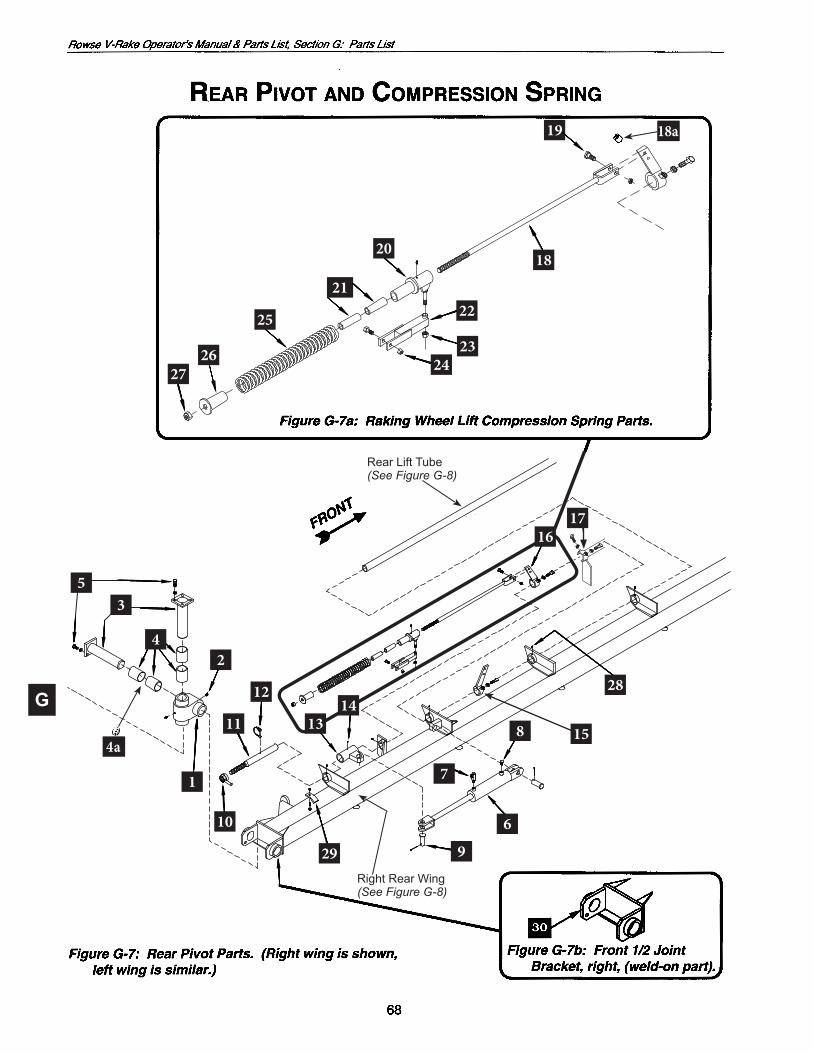
Right Rear Wing(See Figure G-8)
Rear Lift Tube(See Figure G-8)
18a
4a
G
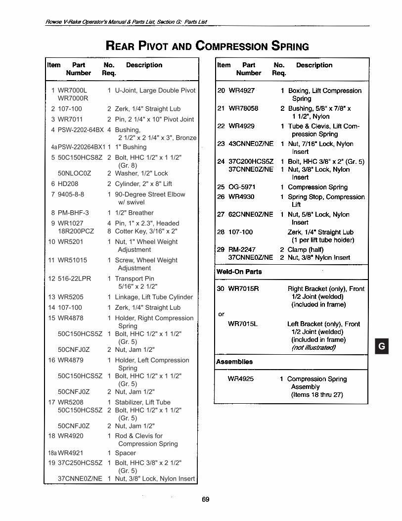
1WR7000L 1 U-Joint,LargeDoublePivot WR7000R 2 107-100 2 Zerk, 1/4" Straight Lub 3WR7011 2 Pin,21/4"x10"PivotJoint 4 PSW-2202-64BX 4 Bushing, 2 1/2" x 2 1/4" x 3", Bronze 4a PSW-220264BX1 1 1" Bushing 5 50C150HCS8Z 2 Bolt, HHC 1/2" x 1 1/2" (Gr.8) 50NLOC0Z 2 Washer, 1/2" Lock 6 HD208 2 Cylinder, 2" x 8" Lift 7 9405-8-8 1 90-Degree Street Elbow w/swivel 8 PM-BHF-3 1 1/2"Breather 9WR1027 4 Pin,1"x2.3",Headed 18R200PCZ 8 CotterKey,3/16"x2"10 WR5201 1 Nut, 1" Wheel Weight Adjustment11 WR51015 1 Screw, Wheel Weight Adjustment12516-22LPR 1 TransportPin 5/16" x 2 1/2"13 WR5205 1 Linkage, Lift Tube Cylinder14 107-100 1 Zerk, 1/4" Straight Lub15 WR4878 1 Holder, Right Compression Spring 50C150HCS5Z 1 Bolt, HHC 1/2" x 1 1/2" (Gr.5) 50CNFJ0Z 2 Nut, Jam 1/2"16 WR4879 1 Holder, Left Compression Spring 50C150HCS5Z 1 Bolt, HHC 1/2" x 1 1/2" (Gr.5) 50CNFJ0Z 2 Nut, Jam 1/2"17 WR5208 1 Stabilizer, Lift Tube 50C150HCS5Z 2 Bolt, HHC 1/2" x 1 1/2" (Gr.5) 50CNFJ0Z 2 Nut, Jam 1/2"18WR4920 1 Rod&Clevisfor Compression Spring18a WR4921 1 Spacer19 37C250HCS5Z 1 Bolt, HHC 3/8" x 2 1/2" (Gr.5) 37CNNE0Z/NE 1 Nut, 3/8" Lock, Nylon Insert
G
19
18
17
121113
14
15 89
163
10
45
67
1
3
3
Figure G-8a: Cut-Away View Showing Spindle (weld-on part).
G
1 *WR7316R 1 Frame, Right Rear Wing 2 *WR7316L 1 Frame, Left Rear Wing (not shown)
3 107-100 2 Zerk, 1/4" Straight Lub 4 14344451 1 Axle, Right Castor, 36" 2 1/4 CRO 5 14344453 1 Axle, Left Castor, 36" 2 1/4 CRO 6 RC156U6CLP 1 Hub&Spindlew/Plate 2x7, 888 * 12420297 1 Spindle,only,w/Plate 7 75C300HCS5Z 2 Bolt,HHC3/4"x3"(Gr.5) 75NLOC0Z 2 Washer, 3/4" Lock 75CNNE0Z/NE 2 Nut, 3/4" Hex
8WR7012 1 Pin,21/4"x14"PivotJoint 9 50C100HCS8Z 1 Bolt,Hex1/2"x1"(Gr.8)10 PSW-2202-64BX 2 Bushing, 2 1/2" x 2 1/4" x 3" Bronze11 *WR7220R 1 Frame, Center Right Wing12 *WR7220L 1 Frame, Center Left Wing (not shown)
13 *WR7520 1 Tube, Front Lift14 WR7125 1 Tube, Joint Link Lift15 50C200HCS5Z 2 Bolt, HHC 1/2" x 2" 50CNNE0Z/NE 4 Nut, 1/2" Lock, Nylon Insert16 *WR7416 1 Tube, Rear Lift

G
76
5
4
8
9
10
11
12
13or
14
15
3
1
2or
G
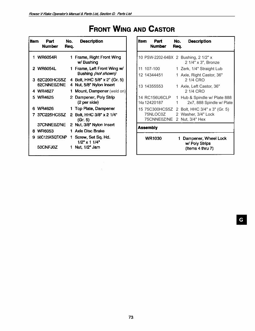
10 PSW-2202-64BX 2 Bushing, 2 1/2" x 2 1/4" x 3", Bronze11 107-100 1 Zerk, 1/4" Straight Lub12 14344451 1 Axle, Right Castor, 36" 2 1/4 CRO13 14355553 1 Axle, Left Castor, 36" 2 1/4 CRO14RC156U6CLP 1 Hub&Spindlew/Plate88814a 12420187 1 2x7, 888 Spindlew/Plate1575C300HCS5Z 2 Bolt,HHC3/4"x3"(Gr.5) 75NLOC0Z 2 Washer, 3/4" Lock 75CNNE0Z/NE 2 Nut, 3/4" Hex
(weldon)
G
1516
1714
1716
1820
1921
2120
1918
1617
17
1615
2
5
911
1
28
28
10
7
13
7
4
3
8
6
27
24
22
2326
7
25
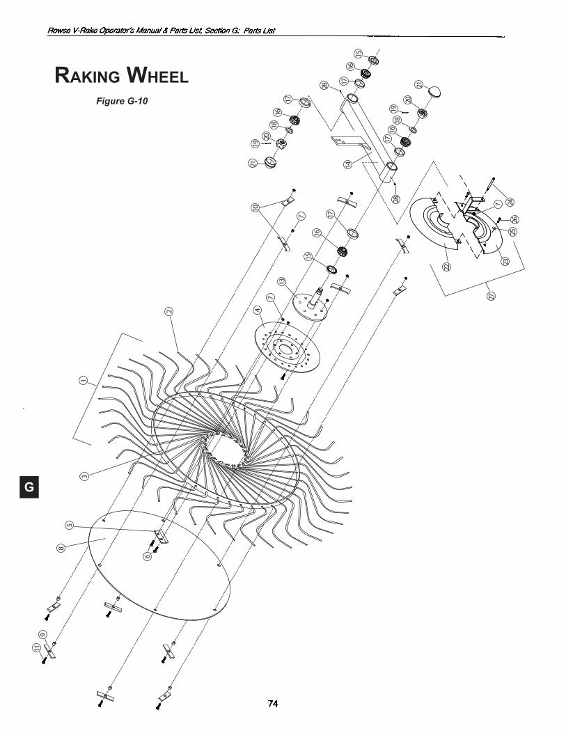
Raking WheelFigure G-10
G
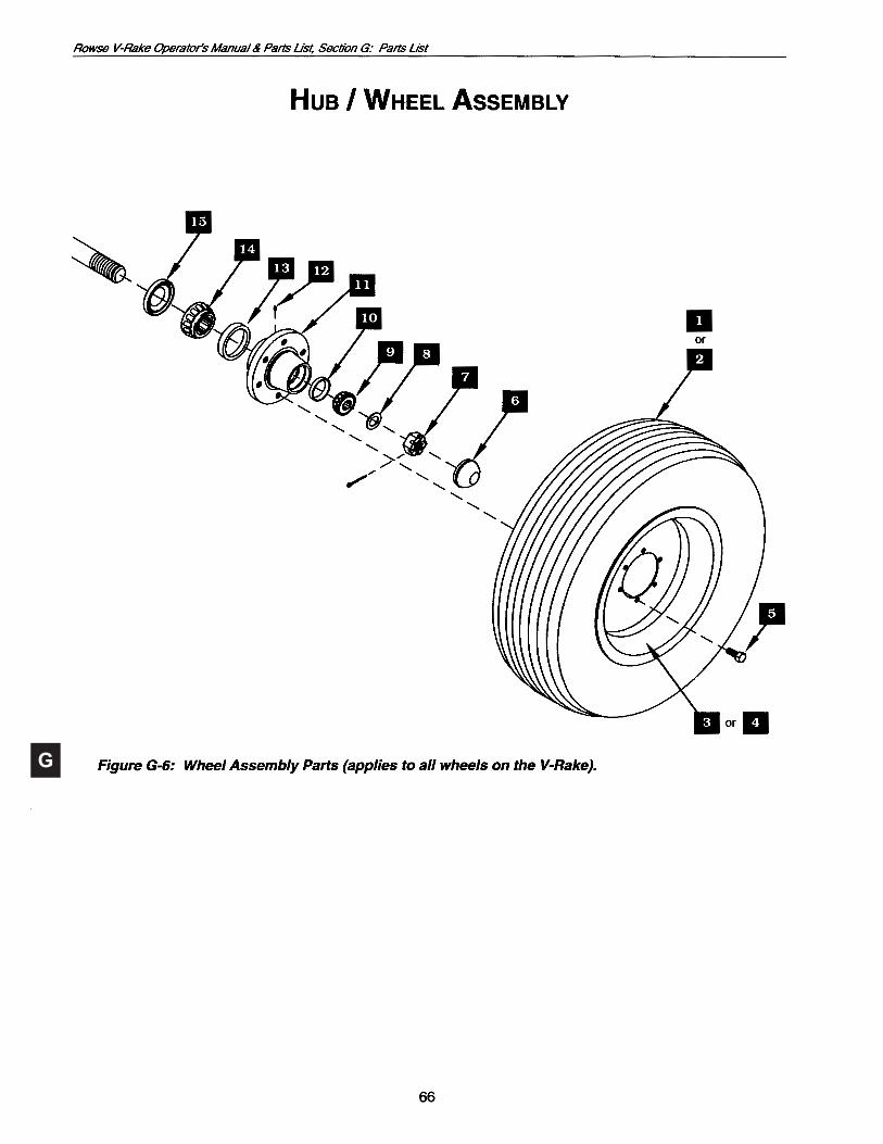
Ref. Part No. Description Qty. Per Wheel Assembly
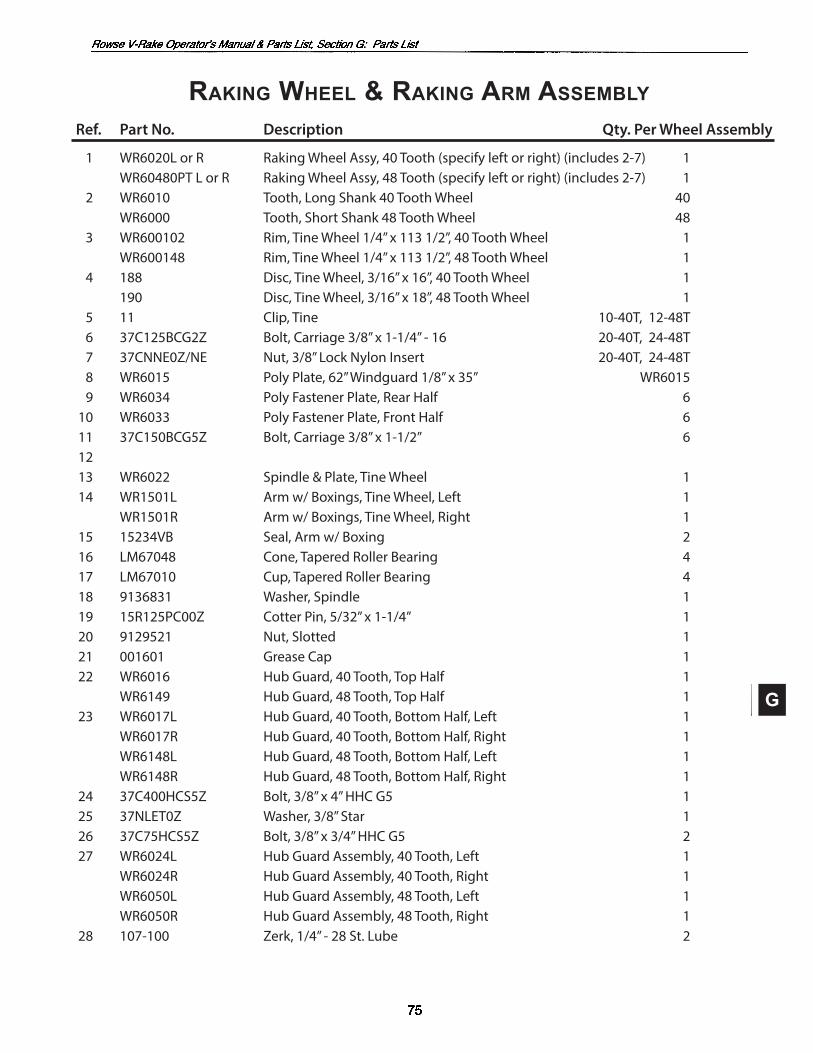
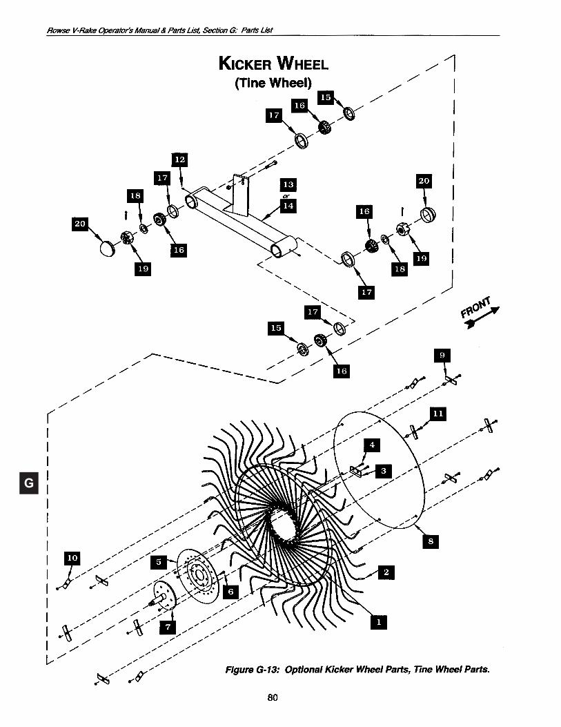
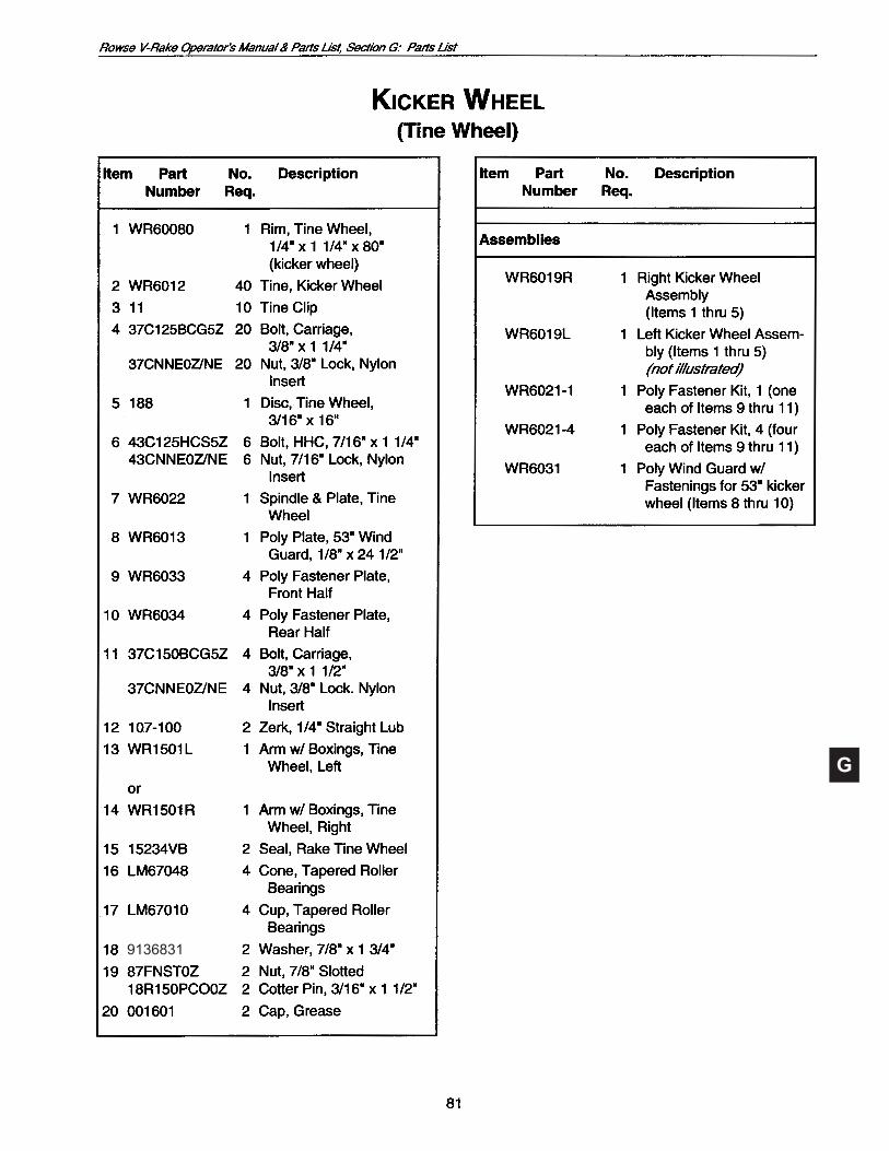
1 WR6020L or R Raking Wheel Assy, 40 Tooth (specify left or right) (includes 27) 1 WR60480PT L or R Raking Wheel Assy, 48 Tooth (specify left or right) (includes 27) 1 2 WR6010 Tooth, Long Shank 40 Tooth Wheel 40 WR6000 Tooth, Short Shank 48 Tooth Wheel 48 3 WR600102 Rim, Tine Wheel 1/4” x 113 1/2”, 40 Tooth Wheel 1 WR600148 Rim, Tine Wheel 1/4” x 113 1/2”, 48 Tooth Wheel 1 4 188 Disc, Tine Wheel, 3/16” x 16”, 40 Tooth Wheel 1 190 Disc, Tine Wheel, 3/16” x 18”, 48 Tooth Wheel 1 5 11 Clip, Tine 1040T, 1248T 6 37C125BCG2Z Bolt, Carriage 3/8” x 11/4” 16 2040T, 2448T 7 37CNNE0Z/NE Nut, 3/8” Lock Nylon Insert 2040T, 2448T 8 WR6015 Poly Plate, 62” Windguard 1/8” x 35” WR6015 9 WR6034 Poly Fastener Plate, Rear Half 6 10 WR6033 Poly Fastener Plate, Front Half 6 11 37C150BCG5Z Bolt, Carriage 3/8” x 11/2” 6 12 13 WR6022 Spindle & Plate, Tine Wheel 1 14 WR1501L Arm w/ Boxings, Tine Wheel, Left 1 WR1501R Arm w/ Boxings, Tine Wheel, Right 1 15 15234VB Seal, Arm w/ Boxing 2 16 LM67048 Cone, Tapered Roller Bearing 4 17 LM67010 Cup, Tapered Roller Bearing 4 18 9136831 Washer, Spindle 1 19 15R125PC00Z Cotter Pin, 5/32” x 11/4” 1 20 9129521 Nut, Slotted 1 21 001601 Grease Cap 1 22 WR6016 Hub Guard, 40 Tooth, Top Half 1 WR6149 Hub Guard, 48 Tooth, Top Half 1 23 WR6017L Hub Guard, 40 Tooth, Bottom Half, Left 1 WR6017R Hub Guard, 40 Tooth, Bottom Half, Right 1 WR6148L Hub Guard, 48 Tooth, Bottom Half, Left 1 WR6148R Hub Guard, 48 Tooth, Bottom Half, Right 1 24 37C400HCS5Z Bolt, 3/8” x 4” HHC G5 1 25 37NLET0Z Washer, 3/8” Star 1 26 37C75HCS5Z Bolt, 3/8” x 3/4” HHC G5 2 27 WR6024L Hub Guard Assembly, 40 Tooth, Left 1 WR6024R Hub Guard Assembly, 40 Tooth, Right 1 WR6050L Hub Guard Assembly, 48 Tooth, Left 1 WR6050R Hub Guard Assembly, 48 Tooth, Right 1 28 107100 Zerk, 1/4” 28 St. Lube 2
Raking Wheel & Raking aRm assembly
G
G
18R200PCZ
31R150RPO/Z
Clip,#6HairPin

G
G
WR6019L, LeftWR6019R, Right
G
G
9136831

G
8
7
Figure G-14a: Cross Fitting.
Figure G-14c: Hose Fitting.
Figure G-14b:Optional Valve.
5
6
25
26
34
2 1
13
20
1917 18
16
14
11
9
1022
1512
21
8
23 7
24

G
, 60"
844905096WR7560
844905018
844905012
844905024844905024
844905030844905030844905030844905030844905030
G
2
1
10
987643
5
21

G
1404-8-8-06
13
1211
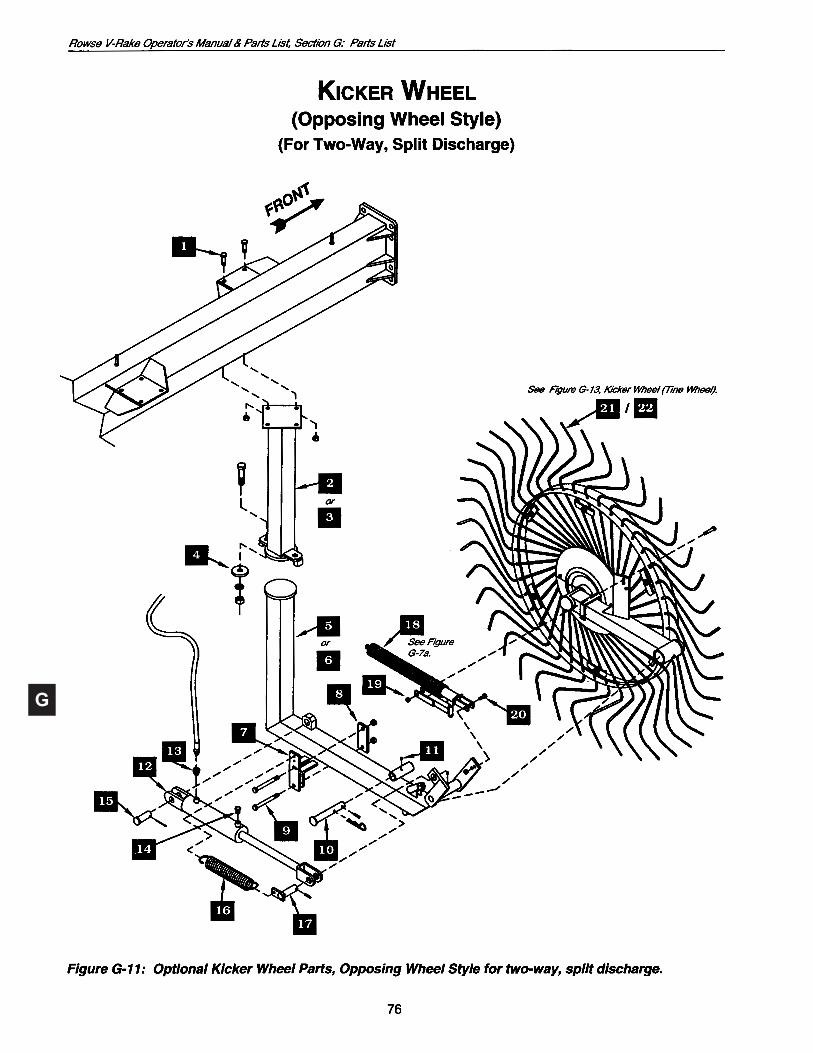
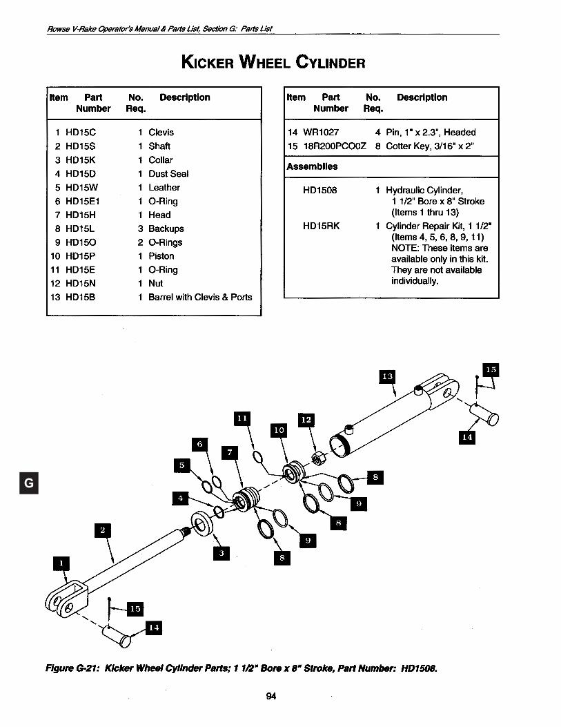
Kicker Wheel Hydraulic Cylinder(TandemWheelStyle)See Figure G-12.
7 8
1
G
G
HD208 2" x 8"
G
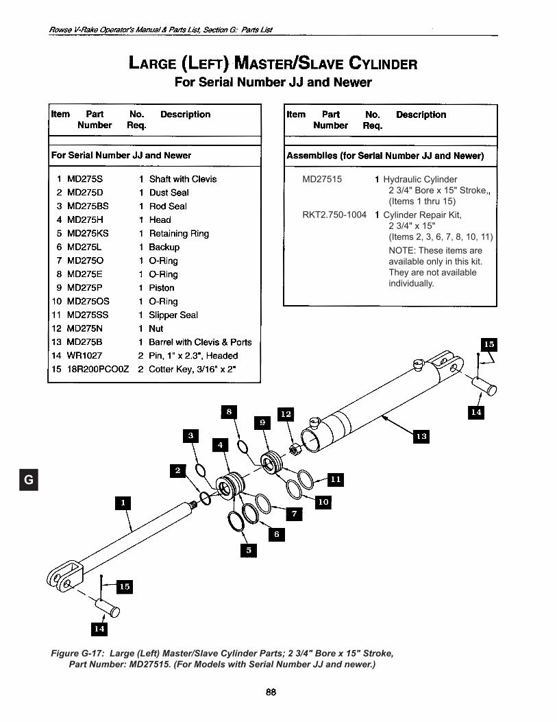
Hydraulic Cylinder 2 3/4" Bore x 15" Stroke, (Items1thru15)Cylinder Repair Kit, 2 3/4" x 15" (Items2,3,6,7,8,10,11)
NOTE: These items are availableonlyinthiskit.Theyarenotavailableindividually.
Figure G-17: Large (Left) Master/Slave Cylinder Parts; 2 3/4" Bore x 15" Stroke,Part Number: MD27515. (For Models with Serial Number JJ and newer.)
MD27515
RKT2.750-1004
G
G
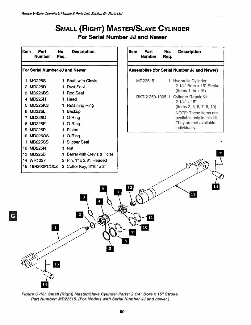
Figure G-18: Small (Right) Master/Slave Cylinder Parts; 2 1/4" Bore x 15" Stroke,Part Number: MD22515. (For Models with Serial Number JJ and newer.)
MD22515
RKT-2.250-1005
Hydraulic Cylinder 2 1/4" Bore x 15" Stroke, (Items1thru15)Cylinder Repair Kit, 2 1/4" x 15" (Items2,3,6,7,8,10)
NOTE: These items are availableonlyinthiskit.Theyarenotavailableindividually.

G

G

G
G

G
7
77
7
8
8
8
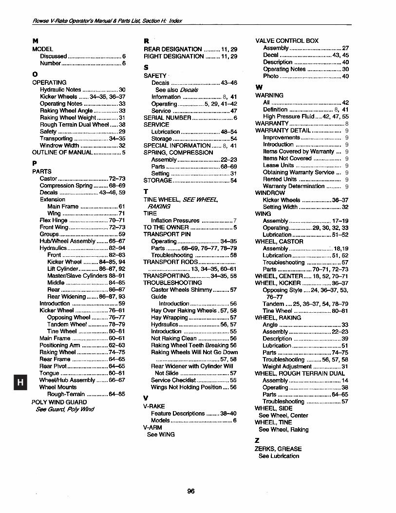
Kicker Wheel ...................... 94
H
8
8
7
8
8999999999