Embed Size (px)
Citation preview

VINYL POOLS
INSTALLATION &OWNER’S MANUAL
3” LED NICHE LIGHT

6
7
13
14
FINISHED INSTALLATION
INSTALLATION INSTRUCTIONS
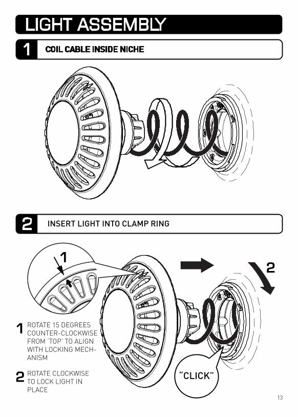
LIGHT ASSEMBLY
WINTERIZATION
READ THIS FIRST 3
4
4
5
16
TOOLS REQUIRED
PRODUCT SUPPORT AND INFORMATION
INCLUDED PARTS
TROUBLESHOOTING
18
KEY DIMENSIONS
MULTI-COLOR OPERATION
CABLE ADJUSTMENT & REMOVAL
23ELECTRICAL GROUNDING / FCC COMPLIANCE
NOTICE
22
21
FRESH WATER USE ONLY HORIZONTAL MOUNT ONLY
NOT INTENDED FOR OPERATION OUT OF WATER
FOR SUPPLY CONNECTION, USE ONLY AN ISOLATING LOW VOLTAGE POWER SUPPLY WITH UNGROUNDED OUTPUT, EVALUATED FOR SWIMMING POOL USE
2
CONTENTS

BEFORE YOU START:• ParaGlo cables can be shortened to suit individual installation requirements. Spa Electrics
recommends all cabling is protected by conduit and that a junction box (or similar) is incorporated into pool cabling design to avoid siphoning.
• Ensure that the lighting system is installed by a qualified person (e.g. registered pool builder and/or licensed electrician), in accordance with the most current edition and/or amendment of current NEC wiring code.
• For safe and proper installation, ensure that only those parts supplied with the system are used. • Maximum installation depth for the ParaGlo 3” light is 1.2ft (14”) below water line (to top of light).• The ParaGlo 3“ light must be correctly installed in or on the wall of the pool with the top of the
lens no less than 4” below the nominal water level. • All lights should be mounted in a location that is easily accessible without the need for entering
or lowering the pool water.• 20” cable has been supplied pre-assembled within niche assembly, and must remain stored
within the Niche to ensure the light can be accessed above the waterline. [Maximum cable within niche = 24” (18AWG & 16AWG). See Page 16 for more information].
CLEANING• Only use warm water and a soft brush or cloth to clean ParaGlo lights. DO NOT use detergents or
spirits as this can damage the light and void your warranty.USE• DO NOT operate light unless completely submerged in water. • Operating the light for at least 15 minutes every week is advised (all year round). • ParaGlo lights are suited for both domestic and commercial installations and can be operated
continuously (24/7) if required.• Temperature range for installation, operation and servicing: +32oF ~ +104oF (0oC ~ +40oC)
The ParaGlo light must only be used with a UL listed 12V AC Class 2 power supply or a power source intended for swimming pool use (not included).Minimum power source wattage requirement - 15 Watts per light.• DO NOT use electronic or switch-mode power supplies with ParaGlo lights. These power supplies
will damage the light and void your product warranty.• Pool chemicals & PH levels: Due to the corrosive nature of unbalanced pool chemicals, Spa
Electrics strongly recommend that your pool water is balanced prior to installing your pool lights or any plastic or stainless steel components, and tested weekly to maintain these levels. pH levels should be maintained between 7.2 – 7.6 at all times to ensure the longevity of these components.
> Failure to do so can result in chemical damage to the light housing and pool fittings, including stainless steel components.
> Please note: Lights or components found to have excessive chemical damage will not be covered under our manufacturer’s warranty policy.
• This light contains no user-serviceable parts; opening the light will void the product warranty.
IMPORTANT NOTE
Congratulations on your purchase of a ParaGlo underwater lighting system.All ParaGlo lights are manufactured by Spa Electrics in Australia from only the highest quality materials and exclusively distributed through Paramount Pool & Spa Systems, USA.
3
READ THIS FIRST

PRODUCT SUPPORT & INFORMATION
Phone: TOLL FREE 1800 621 5886
Email: [email protected]
Web: www.1paramount.com
• 2 5/8” ~ 2 3/4” Hole saw• Box cutter / knife• No. 2 Phillips screwdriver• Flat-blade screw driver (for light-head removal)
IMPORTANT NOTES• The use of power tools during installation is not recommended as these
devices can cause faults and damage to light components.• All installation steps should be carried out with manual tools only.• The enclosed images are for illustrative purposes only. Appearances of parts
and assemblies may vary from the enclosed illustrations.• Please contact your reseller if you have any questions regarding the correct
installation of this product.
WINTERIZATION• It is recommended to remove Paraglo lights in areas prone to hard freezing
below 4”.• Lights should be disconnected from the power cable via the plug top on the
rear of the light. • The RED plug cover supplied must be fitted to the plug top prior to
reinstalling cable into niche for winter.• Consult your local pool professional for complete pool winterization process.Please Note: Damage due to hard freezing is not covered under themanufacturer’s warranty policy.
4
TOOLS REQUIRED
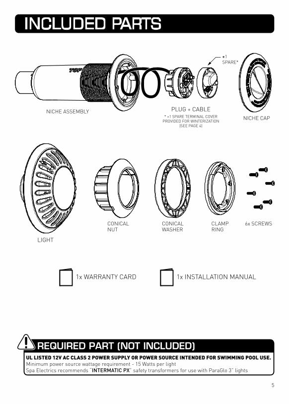
CONICALNUT
CONICALWASHER
6x SCREWSCLAMPRING
NICHE CAPNICHE ASSEMBLY
1x WARRANTY CARD 1x INSTALLATION MANUAL
REQUIRED PART (NOT INCLUDED)UL LISTED 12V AC CLASS 2 POWER SUPPLY OR POWER SOURCE INTENDED FOR SWIMMING POOL USE.Minimum power source wattage requirement - 15 Watts per lightSpa Electrics recommends “INTERMATIC PX” safety transformers for use with ParaGlo 3” lights
LIGHT
PLUG + CABLE* +1 SPARE TERMINAL COVER
PROVIDED FOR WINTERIZATION (SEE PAGE 4)
+1SPARE*
5
INCLUDED PARTS

Depending on your installation requirements, conduits may run to a common junction box or return directly to the power supply. In either case, it is imperative that the conduit extends above the water level of the pool at some point in order to prevent siphoning.
NOTE: Conduit should contain a draw-wire to allow easy installation of power cable.
2ft (MIN) CONDUITELEVATION ABOVEWATER / GROUND
POWER SUPPLY(TRANSFORMER)
VINYL LINER20 MIL (MIN)30 MIL (MAX)
STEEL WALL0.08” (MIN)
14”
(MAX
)
20”
(MAX
)SE
E PA
GE
16FO
R D
ETAI
LS
WATERLINE
COPING
4” (M
IN)
REC
OM
MEN
DED
INST
ALL
DEP
TH
48” (1.22m) MINIMUM
JUNCTION BOX
ELECTRICAL GROUNDINGDUE TO ITS PLASTIC HOUSING AND PLASTIC NICHE DESIGN, THE PARAGLO 3” LIGHT (EMV) LUMINAIRE DOES NOT REQUIRE GROUNDING / BONDING WHEN OPERATED WITHIN A CLASS 2 CIRCUIT SUPPLY.
SEE PAGE 23 FOR MORE INFORMATION
6
FINISHED INSTALLATIONSTANDARD WALL MOUNTING

* MAY NOT BE REQUIRED IF PRE-PUNCHED / DRILLED HOLES AVAILABLE FOR LIGHT MOUNTING
2 5/8” ~ 2 3/4”HOLE SAW
DRILL HOLE THROUGH STEEL WALL
16.7
” (M
AX)
6.7”
(MIN
)
FEED CABLETHROUGHHOLE
7
INSTALLATION PROCEDURE
2
1
ORIENTATION OF NICHE “TOP”
MOUNTING HOLE PREPARATION *

FIRMLY TIGHTENBY HAND ONLY
* GLUING NOTEENSURE P.V.C. SOLVENT CEMENT IS SUITABLE FOR NON-PRESSURE APPLICATIONS AND USE WITH A.B.S. PLASTIC
3/4” OR 1” BELL MOUTH CONDUIT GLUED TO CONDUIT TAKE-OFF
(SEE *GLUING NOTE BELOW)
8
3
4
ASSEMBLE WASHER AND NUT
TIGHTEN NUT

VINYL LINERINSTALLED OVERSTEEL WALL
FIRMLY TIGHTENFASTENERS MANUALLYIN NUMBERED ORDER *
THIS FASTENERLOCATED AT TOP
1
23
46
5
* RECOMMENDEDFASTENING ORDER
9
5
6
REMOVE NICHE CAP
ASSEMBLE VINYL CLAMP RING
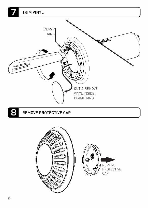
CLAMPRING
CUT & REMOVEVINYL INSIDECLAMP RING
REMOVEPROTECTIVECAP
10
7
8
TRIM VINYL
REMOVE PROTECTIVE CAP
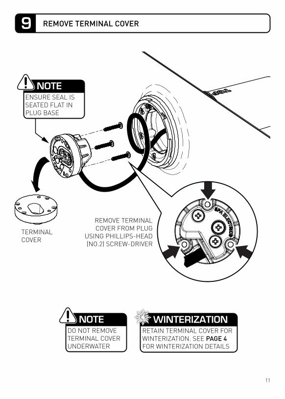
NOTEENSURE SEAL IS SEATED FLAT IN PLUG BASE
NOTEDO NOT REMOVE TERMINAL COVER UNDERWATER
WINTERIZATIONRETAIN TERMINAL COVER FOR WINTERIZATION. SEE PAGE 4 FOR WINTERIZATION DETAILS
REMOVE TERMINAL COVER FROM PLUG
USING PHILLIPS-HEAD (NO.2) SCREW-DRIVER
TERMINALCOVER
11
9 REMOVE TERMINAL COVER

FASTEN PLUG TO LIGHT USING 3 x (M3.5 x 21mm) FASTENERS & NO.2 PHILLIPS-HEAD SCREWDRIVER
ALIGN TERMINAL PINS AND FIRMLY ASSEMBLE PLUG TO LIGHT
• DO NOT OVERTIGHTEN SCREWS• DO NOT USE POWER-TOOLS• DO NOT ADD SEALANTS, GREASES OR ADHESIVES• ENSURE ALL SURFACES ARE CLEAN AND DRY• DO NOT ASSEMBLE UNDERWATER
IMPORTANT NOTES
12
10 FASTEN PLUG TO LIGHT
1
1
2
ROTATE 15 DEGREES COUNTER-CLOCKWISE FROM ‘TOP’ TO ALIGN WITH LOCKING MECH-ANISM
ROTATE CLOCKWISE TO LOCK LIGHT IN PLACE
2
“CLICK”
13
LIGHT ASSEMBLY
1 COIL CABLE INSIDE NICHE
INSERT LIGHT INTO CLAMP RING2
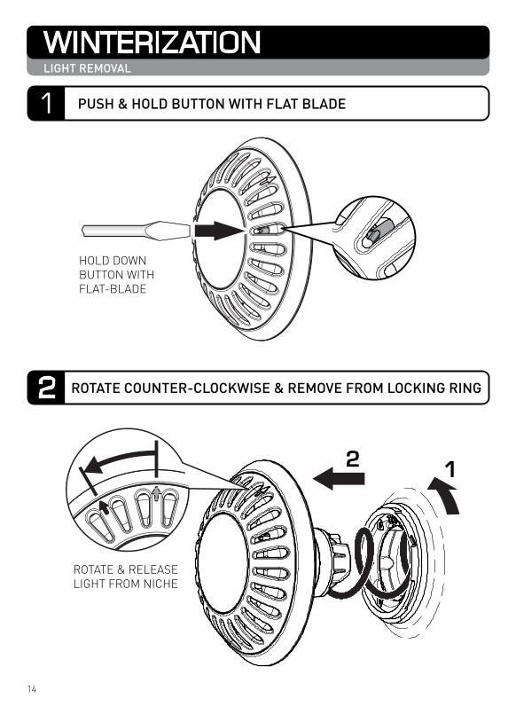
ROTATE & RELEASE LIGHT FROM NICHE
12
HOLD DOWN BUTTON WITH FLAT-BLADE
14
WINTERIZATIONLIGHT REMOVAL
1
2
PUSH & HOLD BUTTON WITH FLAT BLADE
ROTATE COUNTER-CLOCKWISE & REMOVE FROM LOCKING RING

2
UNSCREW 3x FASTENERS USING NO.2 PHIL-LIPS-HEAD SCREWDRIV-
1
ASSEMBLE TERMINAL COVER TO PLUG USING NO.2 PHILLIPS-HEAD SCREW-DRIVER
[RECOMMENDED] STORE PLUG WITHINNICHE DURING WINTER PERIOD
1
2
15
WINTERIZATIONPLUG REMOVAL & TERMINAL COVER ATTACHMENT
3
4
REMOVE PLUG FROM LIGHT
ASSEMBLE TERMINAL COVER TO PLUG & STORE IN NICHE

A CABLE ADJUSTMENT B CABLE REMOVAL
CABLE GROMMET
COMPRESSION PLATE
FASTENERS
20”(STANDARD)
A B
24” (MAX)AFTER CABLEADJUSTMENT
CABLE GLAND
1
2
USING A NO. 2 PHILLIPS-HEAD SCREW-DRIVER, PARTIALLY LOOSEN FASTENERS 1 & 2 TO ALLOW CABLE TO SLIP THROUGH NICHE.
DO NOT EXTEND CABLE LONGER THAN 24” (SEE ABOVE) - EXCESS CABLE WITHIN NICHE WILL RESTRICT CORRECT ASSEMBLY OF LIGHT HEAD.
USING A NO. 2 PHILLIPS-HEAD SCREW-DRIVER, COMPLETELY REMOVE CABLE GLAND COMPONENTS AND STORE SAFELY FOR LATER-USE.
ENSURE CABLE-GLAND COMPONENTS ARE RE-ASSEMBLED TO CABLE IN THE ORIENTATION & ORDER SHOWN ABOVE PRIOR TO FASTENING BACK INTO NICHE.
ParaGlo lights (for vinyl pools) are suppled with 20” of cable pre-installed within the niche. In circumstances where additional cable-length is required, the cable can be extended to a maximum of 24” and stored within the niche. (Applicable for both 18AWG and 16AWG cables).
The following diagrams illustrate how the cable can be adjusted and/or removed:
16
CABLE ADJUST / REMOVAL

• DO NOT OVERTIGHTEN SCREWS WHEN RE-ASSEMBLING CABLE-GLAND COMPONENTS INTO NICHE.
• DO NOT USE POWER-TOOLS• DO NOT ADD SEALANTS, GREASES OR ADHESIVES TO
CABLE OR CABLE-GLAND COMPONENTS AT ANY TIME.• ENSURE ALL SURFACES ARE CLEAN AND DRY PRIOR TO
CABLE & CABLE-GLAND INSTALLATION• DO NOT ASSEMBLE / DISASSEMBLE UNDERWATER
IMPORTANT NOTES
24” (MAX) * AFTER CABLEADJUSTMENT
20” *(STANDARD)
NOTEALWAYS ENSURE POOL LIGHT CAN BE RAISED ABOVE WATERLINE FOR WINTERIZATION & SERVICING
* CABLE LENGTHCABLE LENGTH MEASURED FROM FRONT OF CLAMP RING TO PLUG’S CABLE-ENTRY POINT
17
CABLE ADJUST / REMOVAL

OPERATING INSTRUCTIONS
Multi-Color light models provide a choice of 8 exciting fixed colors & 2 Multi-Color programs with the flick of a switch!
1. Electric Blue2. Midnight Magenta3. Ruby Red
4. Spring Lime5. Lagoon Green6. Tropical Aqua
7. Daylight White 8. Warm White 9. Slow color Blend 10. Fast Color Change
COLORS AVAILABLE:
SYNCHRONIZED INSTALLATION
1. To change the color of the light, simply turn your light OFF for 2 seconds and then turn itback ON. This will signal the light to step through to the next color.Colors will display in the order above, to select a desired color, simply step through thecolors until you find your desired selection.
2.
3.
Your lights will automatically save your selected color once the power has been turned OFFfor more than 1 minute so the next time the lights are used, they will illuminate on thelast color selected.
To reset or ‘synchronize’ your lights; with the power turned ON, turn the power OFF/ON once rapidly. This will put the lights into RESET mode (flashing BLUE), once this occurs turn the power OFF, wait 2 seconds & turn the power ON. Your lights should now be synchronized.
When installing multiple lights; to ensure synchronization and ease of operation alllights must operate from a single switch.
SWITCH
TRANSFORMER
STANDARD 3” LIGHTS
SUGGESTED WIRING DIAGRAM
18
MULTI-COLOR OPERATION1 STANDARD MODEL

EASYTOUCH®, INTELLITOUCH® and SAm® are registered trademarks of Pentair Water Pool and Spa, Inc. and/or its affiliated companies in the United States and/or other countries. AQUALINK® is a registered trademark of Zodiac Pool Care, Inc.
SUGGESTED WIRING DIAGRAM
TRANSFORMER
P-TYPE 3” LIGHTS
CONTROLLER
PENTAIR INTELLITOUCH®PENTAIR EASYTOUCH®
AQUALINK® RS ONETOUCH(REV R - CURRENT)
Spa Electrics recommends “INTERMATIC PX” safety transformers for use with ParaGlo 3” lights
The ParaGlo 3” ‘P-Type’ lights integrate with the Pentair EasyTouch®, IntelliTouch® & ZodiacAqualink® RS OneTouchTM (Rev R - Current) Control systems. This allows the user to have direct control over colors and light shows via the intelligent control unit.
To setup the controller to operate the ParaGlo 3” P-Type lights, simply follow the controllersetup procedure and select “INTELLIBRITE” as the desired operating mode.
IMPORTANT:The ParaGlo 3” P-Type light is not designed to be operated in conjunction with other manufactur-ers lighting products as the colors and shows may not be identical.
19
CONTROLLER OPERATION
2 P-TYPE MODEL (PENTAIR / ZODIAC COMPATIBLE)

If required, the ParaGlo 3” ‘P-Type” lights can function using a standard wall switch. Wall switch operation can be used to select individual colors and shows as well as activate the ’HOLD’ & “RECALL’ feature.
Turning the switch OFF/ON a specific number of times will select one of the five fixed colors or seven light shows available.
To select a different color show mode (1-7) or fixed color (8-12), with the lights turned ON - Turn the wall switch OFF/ON the required number of times. Each number (1-12) below corresponds to the number of times to power cycle the switch to activate the selected show or fixed color.
NOTE: Whenever a different color mode is selected by the user, the light is turned off for a short period (a few seconds) until the new mode is activated. This is normal operating behaviour.
Num
ber
of ti
mes
to c
ycle
pow
er (1
-14)
SWITCH
TRANSFORMER
P-TYPE 3” LIGHTS
1 SAm®: Cycles through white, magenta, blue and green colors. (emulates the Pentair SAm® color changing light).
2 Party: Rapid color changing building energy and excitement.3 Romance: Slow color transitions creating a mesmerizing and calming effect.4 Caribbean: Transitions between a variety of blues and greens5 American: Patriotic red, white and blue transition.6 California Sunset: Dramatic transitions of orange, red and magenta tones.7 Royal: Richer, deeper color tones8 Blue: Fixed color.9 Green: Fixed color.10 Red: Fixed color.11 White: Fixed color.12 Magenta: Fixed color.13 Hold: Save the current color effect during a color light show.14 Recall: Activate the last saved color effect.
SUGGESTED WIRING DIAGRAM
20
2a P-TYPE MODEL (PENTAIR / ZODIAC COMPATIBLE)
MANUAL OPERATION & COLOR MODES
POOL WALL
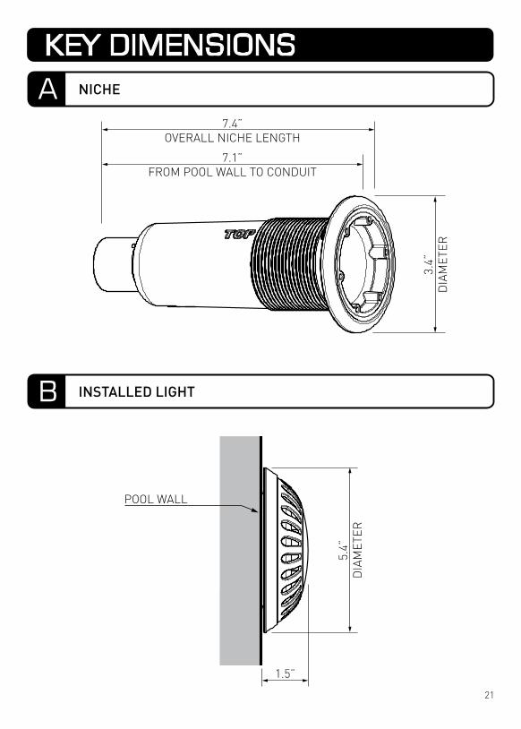
7.1”FROM POOL WALL TO CONDUIT
7.4”OVERALL NICHE LENGTH
3.4”
DIA
MET
ER
5.4”
DIA
MET
ER
1.5”
21
KEY DIMENSIONS
A NICHE
B INSTALLED LIGHT
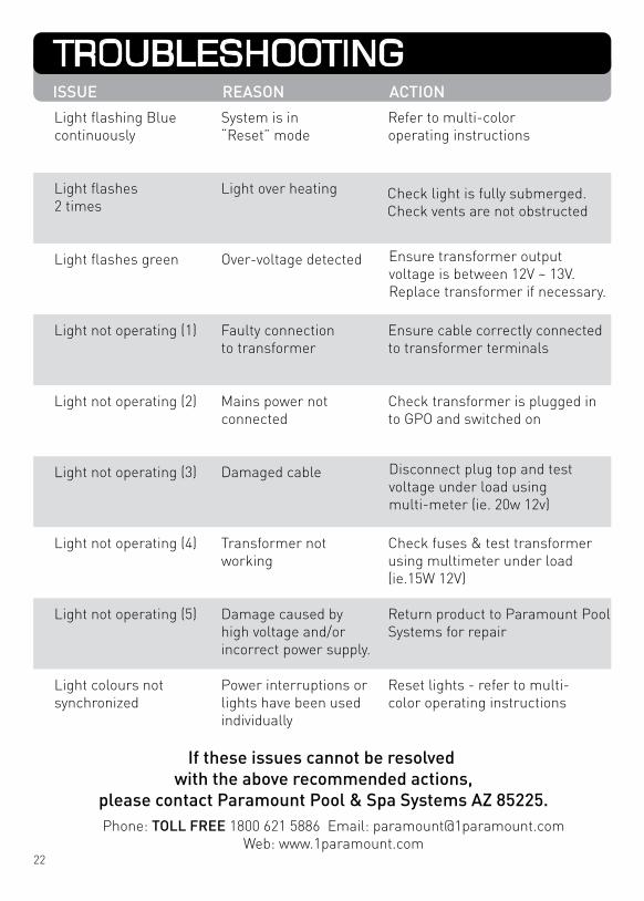
If these issues cannot be resolved with the above recommended actions,
please contact Paramount Pool & Spa Systems AZ 85225.
Light flashes2 times
Light over heating
Light flashing Bluecontinuously
System is in “Reset” mode
Refer to multi-coloroperating instructions
Check light is fully submerged.Check vents are not obstructed
Phone: TOLL FREE 1800 621 5886 Email: [email protected]: www.1paramount.com
Light not operating (1) Faulty connectionto transformer
Ensure cable correctly connectedto transformer terminals
Light flashes green Over-voltage detected
Light not operating (3) Damaged cable
Light not operating (2) Mains power notconnected
Check transformer is plugged into GPO and switched on
Light not operating (4) Transformer notworking
Check fuses & test transformerusing multimeter under load(ie.15W 12V)
Light not operating (5) Damage caused byhigh voltage and/orincorrect power supply.
Return product to Paramount Pool Systems for repair
Light colours notsynchronized
Power interruptions orlights have been usedindividually
Reset lights - refer to multi-color operating instructions
Disconnect plug top and test voltage under load using multi-meter (ie. 20w 12v)
Ensure transformer output voltage is between 12V ~ 13V. Replace transformer if necessary.
22
ISSUE REASON ACTION
TROUBLESHOOTING

Underwriters Laboratories (UL) Statement
Manufacturers Statement
Per the NEC, NFPA 70, Article 680.23 (B)(5), states that bonding shall not be required for luminaires that are listed for the application and have no non-current carrying metal parts. In addition, per Article 680.26 (B)(4), exception states that Listed low-volt-age lighting systems with non-metallic forming shells shall not require bonding.
Therefore, luminaires that are located in the Class 2 circuit with polymeric/non-current carrying metal parts are not required to be grounded / bonded.
ParaGlo 3” & 6” (EM & WN9) luminaires with their plastic housing designs and plastic niches do not require grounding / bonding when operated within a Class 2 circuit supply.
ParaGlo 3” & 6” (EM & WN9) lights have also been determined to comply with the applicable requirements for wet-niche, LED type Swimming Pool and Spa Luminaires.
This device complies with part 15 of the FCC rules. Operation is subject to the following two (2) conditions:(1) This device may not cause harmful interference, and(2) this device must accept any interference received, including interference that may cause undesired operation.
Note: This equipment has been tested and found to comply with the limits for a Class B digital device, pursuant to part 15 of the FCC Rules. These limits are designed to provide reasonable protection against harmful interference in a residential installation. This equipment generates, uses and can radiate radio frequency energy and, if not installed and used in accordance with the instruc-tions, may cause harmful interference to radio communications. However, there is no guarantee that interference will not occur in a particular installation. If this equipment does cause harmful interfer-ence to radio or television reception, which can be determined by turning the equipment off and on, the user is encouraged to try to correct the interference by one or more of the following measures:
• Reorient or relocate the receiving antenna.• Increase the separation between the equipment and receiver.• Connect the equipment into an outlet on a circuit different to that to which the receiver is
connected.• Consult the dealer or an experienced radio / TV technician for help.
Do not make any changes or modifications to the equipment unless otherwise specified in the manual.
23
FCC COMPLIANCE STATEMENT
ELECTRICAL GROUNDING

COPYRIGHT 2015 SPA ELECTRICS PTY. LTD.ALL RIGHTS RESERVED
20150610
NOTEPLEASE STORE THIS
MANUAL IN A SAFE PLACE FOR FUTURE REFERENCE
Proudly manufactured by