Embed Size (px)
Citation preview

s-387Total No" of Pages : 7Seat
No.
T"E (Mechanical) (Semester - V) Eevised) Examinatioq lzlay - 2fllsCONTROL ENGINBERING
Suh, Code t 48709
Day and Date : Thursda yr28- 05 - 20L5
Tinne : 2.30 p.m. to 05.30 p"m.
Instruetions: L) Question No 1 and 5 are compulsory. Solve any two questions fnom
rernaining in Each section
2) Assume suitable data whereyer necessary and state it elearly
3) Figures to thd right indicate full noarks
4) Draw neat sketches whereyer necessary
SEro)N".I
gl) a) Draw the block diagram of a speed control of steam engine system
indicating the f'unetion of each element. t6l
b) Show that the two systems shown in Fig 1(b) are analogous systems,
by cornparing their transfer functions t6l
Total Marks : 100
fi*
*--_J\&/t&t*-u
s
,J +*,
$t<, {
rlr1 ry""I *"'A*.
l4-I
y;*r>.r
It-
I[,vq
{
*
TU;
J
Fie. 1 (b)
P.T.O.

r-
c) Consider Rotational system shown in Fig 1(c)
where J = Moment of inertia of disk
B = Friction constant
K = Torsional sPring constant
and disk subjected to torque T(t)'
Draw its analogous network based on
s-387
t6l
(i) F-V analogY (ii) F-I analogY
r("u
fig - 1(c)
Derive the differential equation which relates input and output motion
*^tat $^* ofaqr{r, [8]of hydralic servomotor, for steady state operation
For sonic flow of air through a fixed restriction, the mass rate of flow is
t8l
,
W
V:
li,r'
flI
\
\
s [*t
Q2) a)
b)
M_ A.P
Where M = Mass rate of flow, kg/sec
T = Inlet temperature, K
A = Area of restriction, m2
P = Inlet pressure' kglfif
Determine the linearized approximation for the variation 'm' when
i) Inlet temPerature is constant
iii) Both inlet temperature and pressure constant
0.53
IT
-)-

s-387Q3) a) The steady - state operating curves for a system to be controlled are
shown in Fig 3(a). The reference operating condition is V.=C.-500,U- =100 and M'=200. Determine the slope of the controller lines suchthat the controlled variable does not deciease by more thnn 4percent ofits reference varue (C = 0.04x500=zo) when lr = r25. tsl
M
250
b) Reduce the given block diagram shown in Fig 3(b) and then obtain rhetransfer function of the system if G,=Gr=l, br=q=2 and, H,=Hr=l,Hr=2
tsl
fig 3(b)
-3-

T-
s-387
84) a) The block diagram.of a feedback control system for operation about a
refer"n", op"riting point is shown in Fig 4(a). The steady state equation
of oPeration is t8l
c=Eir*51,,av l'u au l;
i) Determine the value of KG such that St = 0'05
AC,ii) Determine the value of A such that fr lu= t
iii) For the system to be controlled, what is the slope of the lines of constant U ?
iv) For the system to be qontrolled, deteunine the horizontal spacing AC
between the lines of constant u when au=l0 units
b) Derive the tralsfer function relations for Ac and Dc tachometers' [8]
-4-

---.------
s-387SECTION : II
Qs) a) The loop transfer function of a unit feedback control system is,
G(s) = , ----f,.--_-,53+352+3,5-7
..
Draw the root locus diagram, mark thc salient points and clctermine therange of K for a closed loop system to be stable. , n
t9l
b) A second orcler system is representecl by the transfer function, t9I
0(s)/(s) Jsz + ys+ i
A step input of 10 NM is applied to the system and thc tcst results arc
i) Maxirnum overshoot = 6,Vo
ii) Time at peak overshoot = I sec
iii) The steady state value of the output is 0.5 radians Determine the valuesofJ,fandK
Q6) a) obtain the transfer function G(s) for the following output and srate
space equations y(f)=x,, #=-3x,+x2 and *=-2x,+u(r) tgl
b) The open loop transfer function of a unity FBCS(treed Back control
System) is given by G(s) = *h t8l
i) By what factor the amplifier gain K should be multiplied so thatdamping ratio is increased from 0.2 to 0.g
ii) By what factor the time constant T should be multiplied so that thedamping ratio is reduced from 0.6 to 0.3.
-5-

Q7) a) A control sYstem having,
K62-25+5)G(s)=ffiandH(s)=1
Find
i) Break away Points
ii) Maximum and minimum values of K for stability
iii) Cross over frequency
iv) Angle of arrival
.
b) Determine the comPuter diagram
function of the sYstem as
s-387
t8l
and state space model for a transfer
t8l
r(s) - 2l +e
R(S) 53 + 85? +12S +10
use direct Programming method
es) a) A unity feedback system has G(s) = #ffii, using Routh's
CriterioncalculatetherangeofKforwhichthesystemis
i) Stable
ii) has its closed loop poles more negative than - 1
i,
i
.:
t8l
-6-

s-387b) Determine the state space model and computer diagram for feedback
control system shown in Fig 8(b) t8I
"Ltetr
Fig 8(b)
oo o.o oodb db d6
-7-

s-383Total No. of Pages : 3Seat
No.
T.E. (Mech.) (Part - m) (Semester - V) Examination, May - 2015
Total Manks : 100
[101
HEAT AND MASS TRANSFBR
Sub. Code : 45550
Day and Date : Thursday, 2L - 05 - 20Ls
Time : 02.30 p.m. to 05.30 p.m.
Instructions: L) Solve any three qucstions from Section - I & Section - II each.
2) Assume suitable data if necessary and mention it clearly.
3) Figurcs to the right indicate full marks.
SBCTION . I
Ql) a) Derive the expression for critical radius of insulation for cylinder. 16]
b) Thermal conductivity of plane wall varies with temperature according to
relation kg; : ko (t * B T) where ko and $ are constants. Devclop an
expression for heat flow through slab per unit area if surface at x : o and
x: L are maintained at uniform temperatures T, andT, respcctively.
Hence calculate the heat transfer rate through A: 0.1m2, T, : 200oc,
Tr:0oC, L:0.4m, ko: Uo Y*.C, F: 0.25 x 10⁻⁴ oC-2
Q2) a) Write the general heat conduction equation in cylindrical coordinatcs
and hence derive the relation for temperature distribution in long hollow
cylinder with heat generation rate (Q9) with inside outside temperaturcs
as T, and To respectively Take r, and ro as inside and outside radii. t8]
b) A pin fin of 2.5 cm diameter is provided on surface exposed to air at
27'C. After a steady state the temperatures at two points 7.6 cm apart
were found to be 126' C and 91oC respectively. The heat transfcr
coefficient over the surface of fin is 22.7 Y*rO. What is the thcrrnal
conductivity of fin material? t8l
P.7.0.

s-383
e3) a) A thermocouple junction is in the form of 8mm sphere. Propcrtics of
material are cp :420 %rx.P:8000
nrAr" k: o'Y^ an<lh'= 45
Y*rn Junotion is initially at temperature of 28"C and inserted in hot air
stream at 300"C for 10 seconds. It is taken out after 10 seconds and kept
in still air at30'C with h : rO Y*z1r'Findthe tcmperature attaincd by
the junction 15 seconds after removing from hot air stream. UOl
Discuss Planck's iaw for spectral distribution.
84) The temperature of black body of area 0.1m2 is 900k. Calculatc thc total
lt\
rate ofenergy emission, intensity ofnormal radiationin\\n ".J
maximt m
monochromatic emissive power and wavelength at which it occurcs.
b)
a)
l8I
t8I
b)
Given : C^: 1.287 x 10-sJ
The net radiation from the surface of two parallel plates maintaincd at
temperature T, and T, is to be reduce dby 75 times. Calculate number of
shields to be piaced bletween two surfaces if emissivity of shield is 0.05
and that of surfaces is 0.8. t8l
sEeTIoN --IIGive the significance ofreference temperature in convective heat transi'cr.
What is mean film temperature bulk mean temperature? t8l
Liquid mercury flows through a copper tube of 2 cm inner diametcr at
the rate of 1.25 kg is. The mercury enters at 15oC & is heated to 25oC as
it passes through the tube. Determine the tube length which would satisly
the condition of a constant heat flux at the wall which is at an averagc
temperature of 40oC.
For liquid metals, the following correlation is presumed to agrce
well with experimental results.
Nu:U+0.025(p")o*lWhere,'pe' is the peclet number : pe: (pr , Re) at the mean bulk temp.,
. 15 +25tb: ^" ' -" --20oC,
2
The thermo-physical proparties ofthe liquid mercury are, p : 13580kg/mr;
K:8.685 w/m.k; Cp: 139.35Jkg.kY: l.l45x 10-7 ''f/ 4pr:0'0249'[81
Qs) a)
b)
-)-

s-383
Q6) a) Discuss the mechanism of convective heat transfer in detail. Givc
Newton's law of heating cooling. What is heat transfer coefficicnt? t8I
b) A horizontal cyiindrical heat exchanger of shell diameter 40cm and surfacc
temperature I24"C is to be cooled by ambient air at30'C. Workout thc
convective coefficient and the rate of heat loss from unit surfacc area ofthe heat exchanger. IJse the cortelation, Nu : 0.54 (Gr.Pr) 0.25. Propcrlics
of air at mean film temperature are;
T:20.76 x 10⁻⁶ mzls;k: 0.03003 ilm.k & pr: O.6bl. t8l
Q7) a) Derive an expression for effective of counterflow heat exchanger. t8l
b) 45 kglhr of water is to be heated from 10oC to 70"C with flue gascs
having an initial temperature at 160"C. The massflow rate of the fluc
- t,; ,/
gases is 170 kg/hr. The specific heat of flue gas is t.OS "/pg1<'t'hc
overall heat transfer coefficient rnay be taken as 114 wlmz.l<.
Calculate the heat transfer area required for counterflow typc hcat
exchanger.
Assume specific heat of water as a.18 kj/kg.k.
QS) Write short notes on (Any Three) :
a) Fick's law of diffusion
b) Heat pipe
c) Condensation & its types
d) Forced convection boiling
e) LMTD correction factor
0 Fouling & its types
I8l
u8l
eee
-3-

Seat
No.
s-38sTotal No. of Pages : 4
T.E. (Mech.) (Part - II|) (Semester - V) Examination, May - 2015
MACHINE DESIGN.I
Sub. Code : 45551
Day and Date : Tuesday, 26 - AS - 2015 Total Marks : L00
Time z 2.30 p.m. to 5.30 p.m.
Instructions: 1) Attempt any three questions from each section.
2) Figures to the right indicates full marks.
3) Draw sketches it required.
4) Assume suitable data & mention the same clearly.
SECTION . I
Ql) a) Explain in brief factors govern the selection of material for mechanical
component. t6l
b) what is factor of safety? why it is used in Machine design? tslc) Suggest suitable material for following components giving the reasons.
t6l
i) Automotive cylinder block.
ii) Gears
iii) Flange for coupling.
Q2) a) Explain design procedure of Knuckle joint with the help of neat sketch.
t71
b) Design a right angled bell crank lever having one arm 500 mm and
other 200 mm long. The load of 6 kN is to be raised acting on long
arm end by appling effort at short arm end. The permissible stresses
for lever and pin are 80 Mpa in tension and 60 Mpa in shear. The
bearing pressure is limited to 12N/mm2. The lever is rectangular in
cross -section. Assume depth of lever is three times the thickness and
the pin length is 1.25 times pin diameter. t10l r
Q3) a) Describe the design procedure of bolts subjected to eccentric loading
acting perpendicular to the axis of bolts. t7lb) A bracket is welded to the vertical plate by means of two fillet welds as
shown in figure. Determine the size of welds, if permisible shear stress
tel
P,TO.
is limited to 100 N/mm2.
l
Qa) a)
' Qs) a)
-b.)
b)
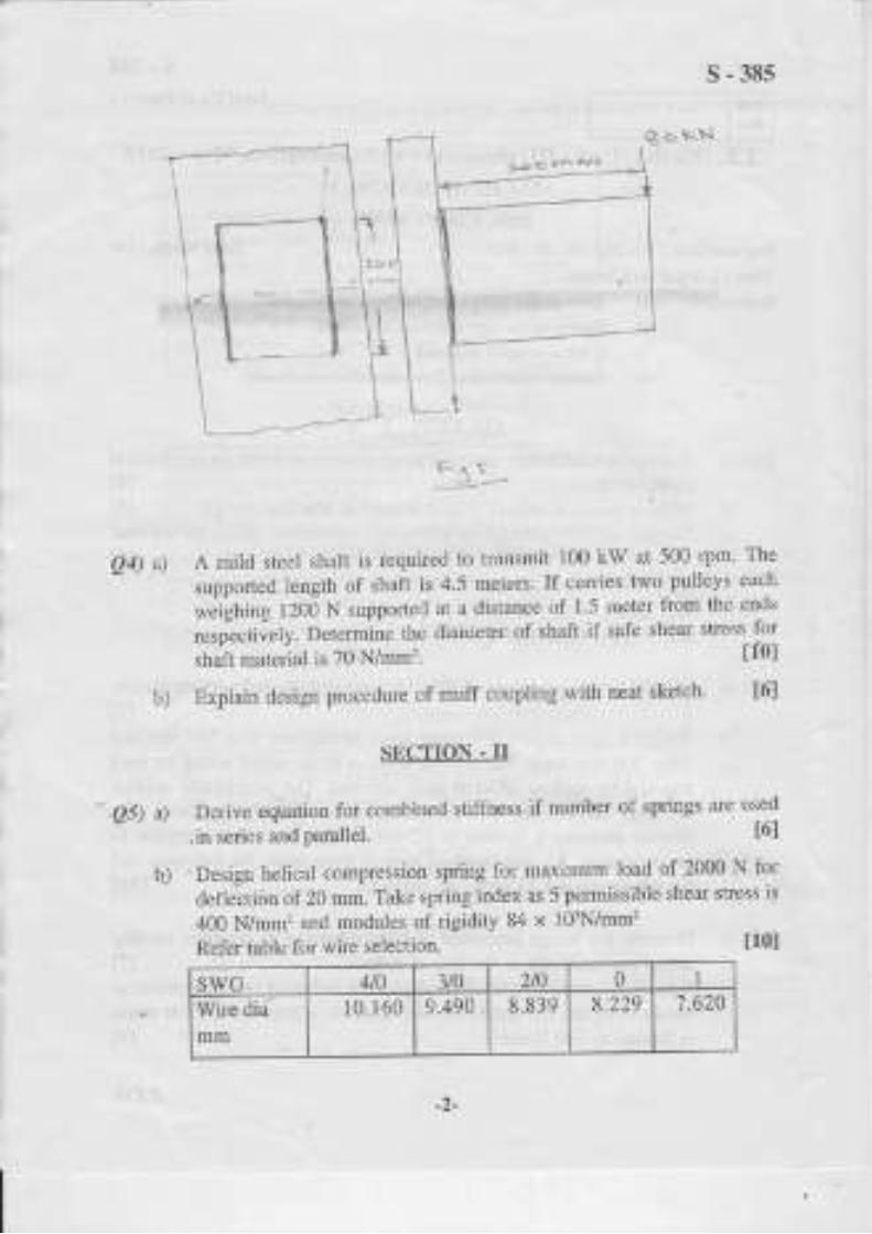
s-385
B * rr't'l
:!*{5 * qt-r q!r?
F qr*L aa*-g
A mild steel shaft is required to transmit 100 kW at 500 rpm. The
supported length of shaft is 4.5 meters. If carries two pulleys each
*"ighlrg l2OO N supported at a distance of 1.5 meter frorn the ends
respectively. Determine the diameter of shaft if safe shear stress for
shaft material is 70 N/mm2. tf0]
Explain design procedure of muff coupling with neat sketch. 16l
SECTTON . II
.:Derive eqiiation for com-bined stiffness if number of springs are used
,in series and parallel. t6l
,Design helical compression spring for maximum load of 2000 N for
defleition of 20mm. Take spring,index as 5 permissible shear stress is
400 N/mm2 and modules of rigidity 84 x 103N/mm2
Refer table for wire selection. t10l
_)-
10.160

T
s-38s
Q6) a) Explain self locking & overhauling preperties of power screw. t6l
b) Square threaded screw exerts load of 50 km with nominal diameter of
100 mm and pitch of 12 mm. Height of nut is 150 mm. Coefficient of
friction between screw & nut is 0.15.
Find
i) Force required at end of rim of 300 mm diameter.
ii) Maximum shear stress
iii) Transverse shear stress
Bearing pressure
Efficiency of Screw
iv)
v)
Q7) Explain eoefficient of fluctuation of energy in case of flywheel.
Two stroke petrol engine develops 15 kW @ 500 RPM. Coefficient
of fluctuation of energy is 1.93 and coefficient of fluctuation of speed
is 0.03. If mean diameter of flywheel rim is 500 mm and hub and
spokes provides SVo of rotational inertia of wheel. Find mass and cross
section of fli4wheel, if deusity of flywheel material (CJ.) 7200 kg/m3.
t10l
Q8) Give various steps to select vee belt from manufacturer's catalogue. [7]
Select flat belt to connect two transmission shafts rotating at 1000 and
500 RPM respectively. Centre to centre distance between shaft is
approximately 2.5 m. The drive is open type. The power transmitted
is 25 kW.
Belt is used to drive centrifugal pump with steady iead
The belt operates at velocity range of 17.8 to 22.9 lWsec. The
power transmitting capacity of belt per mm width per ply at 180o arc
of contact and at belt velocity of 5.08 m/sec is 0.0147 kW.
a)
b)
t10I
t71
a)
b)
Refer data sheet supplied.
-3-
t10l

tlpr *f l*ad xfa
i) N*rrff*l l*tdii} $rcady ln*d, rs.g. centrifugal ptrmp-f*n*-light
m**hin* ti-:r:ls * **Itv*y*r$
iii) lxrs:lxilfent I**d, *.9. lt*tvy ttuty f*ns - bleiw*rs
u*mpfi:s$firx - r*eipr*ceting putllps - linr. *h*fts
he*vy cl*ty rm*ehin*s
iv) $h**k loael, *,"g, S*f.uum pt]ntX]$ - r*lii*g nrills
hanrmers - Srindrm
r.*
rn
1.3
1.5
s-38s
L*nd c*rrectium fm*t*r {S*}
&rs *f &lnfs*[ fhct*r {}'*}
' if r"r "u " .14:1 ^
i *f:thise 5$f6,{iii''}mm}
3-trIy
4-Ittry
5-PIy
{i.}}ly
tc
4*
?s
1t?
4* 5*
44 5fi
1{X} i rr
i:.5 I53
63 ?6
s3 ?fi *{} 1il{} t}? 1?5 15?
t15 t5}
ts0 ?(xi
vvv
& {Sryrtm) n3s 13{} 14.S ls0 rs{} 1?fi 1S* Isil ?*tl
Ir'd L-ri t.3s t. t$ t.t3 r"fis , "04 I.t]S *,E? fi,q4
-4J

Seat
No.
s-384Total No. of Pages : 3
T.E. (Mechanical Engineering) (Semester' V) (Revised)
Examination, May - 2015
MANUFACTURING ENGINEERING (NCW)
Sub. Code : 45565
Day and Date : Saturday, 23 '05 'zlfiTime : 1.30 p.m. to 5.30 p.m.
Instructions: 1) Question No. 1 and Question No.5 are compulsory.
2) Solve two questions from remaining questions of each section.
3) Figures to the right indicate full marks.
4) Assume suitable data wherever necessary and state it ciearly.
5) Use of non programmable calculator is allowed.
SECTION - I
QI) The component shown in Fig. 1 is to be processed on a single spindle
automat. Study the component and prepare t18I
a) Detailed process sheet
b) Tool Layout
c) Cam profile for drilling operation
d) Calculate production rate per hour
re {{l-.lLr,Jg.**r
F'tll+fs'&rrt&' r ?Ji:-
bntr
rttl di*lrfi'*tsh$ 4YC tta r*rt'r*
Total Marks : 100
4+
Fig.l
P.TO.

Q2) a)
b)
c)
Q3) a)
b)
c)
s-384
Differenti ate clearlv between orthogonal and oblique cuting operation
t4lwith neat sketch.
Discuss in brief the methods of reducing BUE formation during metal
cutting.
The following values relate to a cutting test under orthogonal cutting
conditions for machining of aluminum. Forces determined are
F, = 1500 N, F, = 1000N, A = 10", r='y'h=0.37 ' Determine as per
METChANI'S THEORY THE CUTTING FORCES NS' FS'N ANd F.
Also determine the co-eff. At chip tool interface. t8I
Discuss in brief the factors affecting surface finish.
Discuss in brief the selection criteria for cutting fluids.
A mild steel billet 150 mm Dia. was turned with a carbide tool at 30
m/min. The tool life observed was 2.1 t*. At the cutting of 25mlmin
tool life observed was to be 5.2Ik. Derive Taylor's equation for the
system.
Q4) Write short notes on (AnY Four):
a) Types of chiPs
b) Tool materials
c) Tool signature
d) Tool dYnamometers
e) Tool wear
D Form tools
SECTION . II
t16I
e5) Design and draw neat dirnensional drawing in three views with one sectional
view of a jig for drilling two holes $12 as shown in fig. II. Show clearly the
details of location, clamping and guiding elements. Assume this as a final
operation t261
t41
t41
t4l
-2-

+
s-384OR
Design and draw neat dimensional drawiag in three views with one sectional
view of a milling fixture for milling the 2O + 0.05 mm wide slot at the
component shown in fig. II. Show the details of location, clarnping and
setting of cutter. Assume this as a final operation.
3-**BLEEi,
a5e l+
e H$LES.
F'6-ll
Q6) a) List the different methods of reducing cutting forces in press working.Explain what is shear on punch. t6I
b) Explain with neat sketch what is strip layout in press working. t6l
Q7) a) List the methods of distributing the depreciation and explain any one
method in detail.
b) Explain the concept of machine tool replacement.
Q8) Wfte short notes on any two.
a) Economics of tooling
b) Quick acting nut
c) Press working terminology
d) Center of pressure.
{JV
-3-
' t6l
t6l
t12l
s - 1520
Total No. of Pages : 3Seat
No.
' May - 2015
MBTROLOGY AND QUALITY CONTROL (New)
Sub. Code | 45564
Day and Date : Saturday,30 - 05 - 2015
Time : 02.30 p.m. to 05.30 p.m.
iotal Marks : 100
Instructions: L) Answer any three questions from each section.
2) Figures to the right indicate full marks.
3) Draw neat labeled sketches wherever necessary.
4) Assume if neccssary suitable data and state them clearly.
5) Use of non-programmable calculators is allowed.
81)
SECTION - I
Distinguish between measuring instruments and comparators. tSl
Explain the procedure to transfer line standard to end standard. t8l
Explain Taylor's principle of gauge design. What do you mean by
gauge makers tolerance and wear allowance. t8l
Calculate tolerances and limits for hole-shaft pair designated as
@45H7 96 and also determine the minimum and maximum clearance.
The dimension @45 lies between the range 30-50mm. Fttndamental
deviation of g-shaft is -2.5D0'3a. The standard tolerance is given by
Q2) a)
i = 0.45D1/3+ 0.001D(microns)
Q3) a) Explain the principle of interference of light and state the necessary
T.E. (Mechanical) (Part - I) (Semester - V) Examination,
conditions for interference of light.
b) Explain the use of sine bar for measuring an angle with the help of
a)
b)
b)
t8l
t8l
t8l
P.T.O.
neat sketch and state its limitations.

s - 1520
Q4) Wfite short notes on (any three): t18I
a) Slip gauges
b) Sigma comParator
c) Attto collimator
d) Measurement of convex surface radius
e) Flatness testing of surface plate
SBCTION . II
e5) a) State the various elements of a screw thread. Explain 3 - wire mcthod
to measure the effective diameter of screw thread. t$l
b) Explain the use of gear tooth vernier caliper for the mcaslircmcnt of
gear tooth thickness. t8la-
eG) a) Define quality control and state the objectives of quality control. t6I
b) Following data was obtained for diameter of a component [r'om shop
floor. Construct X and R charts and state whether the process is in
control or not. t10l
Sample No. x R
1 50.04 0.07
2 50.24 0.08
4J 5A.14 0.03
4 50.08 0.05
5 5A.28 0.04
6 50.16 0.09
7 50"30 0.04
8 50.10 0.04
I s0.16 0.05
10 50.10 0.07
Foi a sample of size "5" take A2-A577, D4=2-114, D3=0
_7-

s - 1s20
Q7) a) Differentiate between l00Vo inspection and sampling inspection. I8l
b) What is cost of quality and explain cost of failure, cost of appraisal and
cost of prevention. tSl
Q8) Wnte short notes on (any three) : t18l
a) Tomlinson surface meter
b) Pitch measuring machine
c) Parkinson gear tester
d) Chance causes and assignable causes
e) Operatingcharacteristicscurves
3t 3E 3E
-3-

Seat
No.
Examination, April _ 2016
THEORY OF MACHINES - IISub. Code : 45549
Day aDd Date : Friday,29-04-2016
Time: 10.30 a.m. to 1.30 p.m.
Instrurfions i 1) Attemptany three questions from each sectior.2) Figures to the right indicate fullmark!.3) Assumo suitahlc data, ifnccessary anrl statc clearlv_
Q1)
?2) Write a note on various types olgear trains.
An epiclclic gecr rr.ain is shown irr fig.2.b.
P_507Total No. of Pages i 4
a)
b)
a)
b)
T.E, (Mechanical) (Semester - V) (OId) (pre_revised)
SECTION . I
Derive the expression for efficiency in case ofspiral gears. 16l
A pinion.having 30 teeth drives a gear having g0 teeth. The profile ofthegears is involute with 20" pressure angle, 12 mm module and t0 mmaddendum. Find the length of path of contact, ur" of
"ontu.t *d th"
contact ratio. t10l
Total Marks : 100
t6t
u01
.t\ a.
L.L
PT,O.

P-5o',
The annular gear A has 72 teeth and meshes widr gear B. Gear C has 3
teeth and is engaged to Gear B. A:rn EF which canies gears B and I
rotates at a speed ol18 rp.m. Ifgear A is fixed, determine the speed c
gears B and C.
Q3) a) Wiite a note on stability ofa two-wheeler while taking a tum. J6
b) The turbine rotor of a ship has a mass of 8 tonnes and a ladius c
gy'ation of 0.6m. lt rotates at 800 rp,m. clockwise when looking lrorstem end. Detemline the gyroscopic couple and its eflect if the shj
tuavels at 40 km,/k and steers to the left in a curve of75 m radius. [10
Q4) a) Explain balancing of several masses rotating in the same plane. [6
b) A, B, C and D are four masses canied by a rotating shaft at radii l8r
mm, 240 nrm, I 20 mm and 150 mm respectively and the masses of B, C
and D are 30 kg, 50 kg and 40 kg respectively. The planes containinl
massesB ald C are 300mm apart. The angie between theplanes containinl
B and C is 90". B and C make angles of2l0,,and 120,, respectively witlD in the same selse.
Find: i) The magnitude and angular position ofAand
ii) The position ofplanes A and D,
112
SECTION - II
Q5) a) With the help of neat sketch represent vector method to represen
vibratory motion and derive the lelalions between displacement vectot
velocity vector and acceleration vectol l8l
_1_
Fiq.5b
Q6) a) What is meant by coulomb damping? Explain the rate of decay oosc rations in this case "'","'".rr o, 1gl
O, 1 qo., of5 kg is supponed or a spring ofsriltiess 200 N rn and ha:dashpoL connecred io ir ,nhicl- p.odr..r r,;;;;;;;;.-;;;;;f,,u r,,vetocity of I cn/sec. In whar rariorvil rh. ";;ll;;;;, u,frrir,", o"reduced after 5 cycles.
- "'- -"'vu!suu ur vroral
tgJ
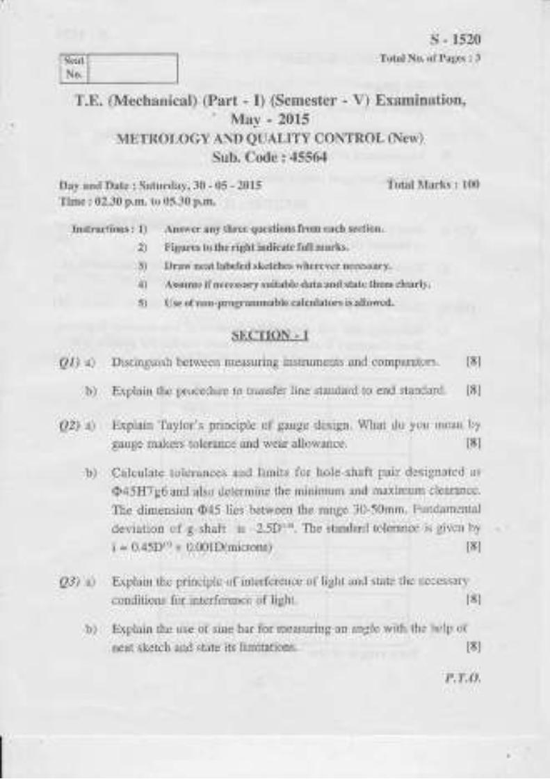
A pendulunr,consists ofa stiffweightless rod oflength / canlingP;:lz on rts end as shown in Fis. 5b. nartached to ,h" ;;;; ;j;,;:"JU.
, wo spungs each of sriffness t ,
narurar rreq,renc; ;;;;;;,i;:.1, ";Ilf
. ,00., enci. Derennin..r
D-erir e an expression for.ampiittroe rario o fa single degree freedonr s) sremsubJccled lo harmonic exciration Fsinoi. ,"i;;
A 1000 kg rnachine is mounled on four idenrical springs oftotal sorino
llll,:]* ,1,1o n,l ,:g nesrigih,e dan-ping ,r.,,Jni,ii, r,i;..,il,",inanlonrc exterrral tblce of amolinr,
,pm De e,mrne rhe;;; ;;,: #;:T": ".J:',):ffii:i:ffr_:l:Jorce rransmined ro loundarion bccause ol rh.,rrb"lun;;i;;,JJ*;.;k- i.06.16"17r.
lt6l
b)
-TI
Q7) a)
b)
-3-

Q8) a) Describe Lhe phenornenon of .whirr P-507
toramplirude ofvibrarion of.ha fi ro]:.9.of shafl' and clerive the lonnula
a singie disc "r
,.r; .r".' ;;ilr"t:trng with angular spced o having
:::.:,:,:'q ...
*i,,," *.",",.,i1::::. lr::::i.;In..;f;,T;.J:. floamprng. l8l
A machjne is supported by four isolz
): :'1 1'' r,,, * i"*.i.;l: ;?l i::',:i'#J; ;'.:l T ;T :: il::rrom a support fiaving an amolitude n,",.' " i I...r, ;
".
",. : ; -::''J:[[:f
i; J]x. i: j:r$: li:i:f :lt8t
+++
b)
-4-

P- s08Total No. of Page6 :3Seat
No.
T.E(Mechanical)(Part-tll)(Semester -V)(Okl) (Revised)Examination, April - 2016
IM,AT AND MASS TRANSFERSub. Code: 45550
Day and Date :Saturday, 30 - 04 - 2016 Total Marks :100Time :10.30 a.m. to 1.30 p.m.
Instructions : 1) Solv€ any threc questions from each section.2) Write suitable assumptions wherever necessary anal state it clearly3) Figures to the right indic.te full marks4) Use of scientilic calculator is permitted.
SECTION-I
Ql) a) lvhat do you mean by thermal conductivity what is the effect oftemperature on thermal conductivity for various engineering material. [gl
b) A thick walled tube ofstainless steel is 20 mm inside diameter and 40mm outside diameter is covered with a 3 Omm layer ofasbestos insulationCk=0.2 mk ifthe inside wall temperature ofthe cylinder is maintainedat 600"C and the outside insulation at 1000.C, calculate the heat loss permeter length ofthe pipe neglecting the resistance of stainless steel pipeJtl
Q2) a) Derive the expression for temperature distribution and heat transfer for aplane wall with uniform heat generation
t8l
b) The temperature on the two surfaces ofa 25 mm thick steel plate(F40Wmk).having a uniform volumetric heat generation of 30;105Wm3 are180'C and 120.C. Neglecting the end effects determine:
! The temperature distribution across the plane wall
ii) The location and the maximum temperature in the slab. lgl
Q3) a) Derive the expression for temperature distribution and heat transfer for a
t8l
P,T.O.
ininitely long fin.

-
P-508b) A mercury thermometer placed in oil well is require to measure temperature
ofa compressed air flowing in a pipe. The well is 140 mm long and is
made of steel (k=50 Wm"C) of 1mm thickness. The temperature
recorded by the well is 100"C, while pipe wall temperature is 50'C. Heat
transfer coefficient between the Air and the well is 30WmoC. Estimate
true temperature of air.
Q4) Write short notes(any three)
a) Radiation shield.
b) Plank's distribution law
c) Radiation shape factor
d) Spectrumofelectuomagneticrudiation
e) Radiation heat transfer befween concentric cylinders.
I8I
[18]
SECTION-II
Q5) a) What are the various dimensionless numbers used in convection heat
transfer? Give the signihcance of each number t8l
b) A Nuclear reactor with its core constructed of paxallel vertical plates
2.2m high and 1.4 mwidehas been designed on free convection heating
of liquid bismuth. The maximum temperatwe of plate surface is limitedto 960 'C while, the lowest allowable temperature ofbismuth is 340 oC.
calculate the maximum possible heat dissipation from both the sides ofplate. Use the following co- relation
Nu:O.l3(Gr.Pr)o nr The thermodynamic properties ofbismuth are:
p:0.000867 N/m-s, Cp=150.7Jlkg oC, K=13.02Wm 'C,p:1.08x10⁻³k' t8l
Q6) a) Analyse the problem offorced convection by using dimensional analysis
technique. l8lb) A tube 5 m long is maintained at 10Onamic properties ofbismuth are:
p = 0.000867N/m--s, Cp:150.7 J/kg "C by steam jacketing. A fluidflows through the tube at the mte of2040kg,t[. at 30'C, the diameter ofthe tube is 2cm frnd the average heat ftansfer coefficient. Following are
the properties offluid;p=850kglm1,Cp1000J&g"C, K=0. 12WmoC, p:1 9.8x 10⁻⁵ N-s/m'z
Use Nu = 0.023 Reor ProI. t8l
-2-

P-508
Q7) a) Derive the expression for LMTD for parallel flow heat exchanger, state
tle assumptions made. 18l
b) The flow rates ofhot and cold water streams running through a parallel
flow heat exchanger are O.2kgls and 0.5 kg/s respectively. The inlettemperatues on the hot and cold sides are 75'C and 20.C respectively.The exit temperature ofhot water is 45"C. ifthe individual heat transfercoetl ci ents on both sides are 65 0 Wm, oC,
cal cul ate th e arca of the heatexchanger. l8l
Q8) Write short notes on the following (any three)
a) Fick's law of diffusion.
b) Overall heat transfer co-efiicient for heat exchanger.
c) Heatpipe.
d) Boiling and condensation.
lrsI

t-=--II
Seat
No.
P-s09Total No. of Pages : 7
T,E. (Mechanical) (Part-t) (Semester-V)
Examination, May - 2016
MACHINE DESIGN*I
Sub. Code: 4555I
Day and Date ; Monday, 02- 05 - 2016 Total Marks : 100
Time : 10.30 a.m. to 1.30 p.m.
Instructions: 1) Answer any thr€e questions from each section,
2) Figure to the right indicates full marks,
3) Make suitable assuhptiols wherever requir€d and state Jhe srmeclearly.
SECTION.I
Q1) a) Explain the various factdr influencing the selectionparticular application.
b) Suggest with justification the suitable material for the followingcomponents- 16l
D Lathe bed"
ii) Crank shaft.
iii) Surgical instruments.
c) State the different theories offailure & explain one ofthem. t6l
Q2) a) Which are the different types of keys used for shafting. Explain thedesign procedure for sunk key. 16l
P1:O.
of material for a
l6l

P-509b) Design a tum buckle for an axial toad of 50 kN. A1l parts are made of
steel having following propedies-
Allowable tensile sftess (q) = 140 N/mm'z.
tt0I
Allowable shear stress ({): 75 N/mm'?.
Allowable crushing stress (f") : 160 N/mm'.
Draw critical areas where failure is likely to take place & draw a sketch
oftum buckle showing imponant dimensions.
Q3) a) Explain the design procedure of eccentrically loaded welded joint
subjected to primary sh€ar strcss due to direct load and secondary shear
sffess due to tuming moment as shown in Fig. 3aJ. t6l
PKN
b) A bracket is boited to a veftical pillar using six bolts; 2 bolts in each row
as shown in Fig. 3b-L The bracket carries a load of 24 kN. Assuming
tensile stress for the bolt material as 80 MPa determine the bolt size.
u0l
-2-

Q4) a)
P-509
2-4 KN.
Fig. 3b-I
Discuss the advantages of welded joints over the bolted and rivetedjoints. l4l
Design the rigid flange coupling to transmit 40 KW at 1 80 rpm. Overloadfactor for the application is 1.5. Allowable shear stress for the shaftmaterial is ({) = 79 MPa; for key and bolt material premissible shearstress is 80 MPa and crushing stress is 240 MPa. Altowable shear stress
for flange material is 16.67 MPa. No. of bolts used are 4. Draw a
dimensional sketch of the coupling.
b)
-3-
lt21

P-509SECIIONdI
Qs) a) Explain the suesses induced while designing a helical compression spring
alongwith neat diagrams. 16l
b) Design ahelical compression spring for a maximum load of 1000N for a
deflection of25 mm, using the value of spring index as 5. The maximum
permissible shear stress for spring wire is 420 N/mmz and modulus of
rigidity is 84 kN/mm2. Also draw neat sketch ofthe spring Take Whal's
1a_ r n 615
facror K=;;t: . The std. wire gauge (SWG) number and
coresponding diameter ofspring wire is given in following table. [101
svr'G 1 2 3 4 5
Diameter(mm) 7 .620 7.0t 0 6.401 5.893 5.385
Q6) a) What do you understand by overhauling and selflocking ofpower screw?
How does it affect the efftciency ofscrew? t6l
b) Atdple start square threaded screw isused to raise a load of50 kN The
screw has a nominal diameter of 50 mm and pitch ol8 mm, height ofnut
is 40 mm and coefficient of friction between nut and screw is 0 12'
There is no collar friction. Find the maximum shear stress induced in the
screw arld nut tkeads. A[so find the bearing ptessure between screw
and nut. [10]
-4-

Q7) a) Derive an expression for energy stored in flpvheel.
P-509
t8l
b) A rimmed flyrvheel made of grey cast iron having mass density of7100
kg/nt' is used on a punching press running at a mean speed of200 rp.m.
The punching operation consists of one quarter revolution during which
the fllrvheel is requiredto supply 3000N:m of energy. The coefiicient of
speed fluctuatioos is limited to 0.2. The rim which contuibutes 9070 ofthe required moment ofinertia, has a mear radius of0.5m due to space
limitations. The cross-section of the rim is square. Detemine itsdimensions- t8l
Q8) a) Give in steps the procedure for selection ofV-belt ftom marufacturers
catalogue. t81
b) It is required to select a flat belt drive to comect two transmission shafts
rotating at 800 and 400 rp.m. respectively. The centle-to-centue distance
between the shafts is approximately 3m and the belt drive is open type.
The power transmitted by the belt is 30 KW and the load correction
factor is 1.3. The belt should operate at a velocity betlveen l7 .8 t$ 22.90
n/s. The power transmitting capacity ofthe belt permm width perply at
180o arc of contact and at a belt velocity of 5'08 m/s is 0.0147 KW
Select preferred pulley diameters and speci$ the belt.
Refer the data given for Q. 8 (b) u0l
-5-

P-509Load correction factor (F,)
Arc of contact factor (Fo)
Type of load F
Normal load
Steady load, e.g. centlifugal pumps-fansJight
machine tools - conveyors
Intermittent load, e"g. heary duty
fans - blowers compressors - reciproaating
pumps - Iine shafts heary duty machines
Shock load, e.g. vacuum pumps - rolling mills
hammers - grinders.
iii)
w)
1.0
1.2
1.3
1.5
o[, ( degees) 120 r30 140 I50 160 170 180 190 200
F 1.33 1"26 1.19 l.t3 1.08 1.04 1.00 o.97 0.94
-6-

3-P1y I Zs 40 50 63 76
+-ely | 40 M s0 63 '76 90 100 ll2 12s 1s2
s-Ply | '16 100 112 12s 152
o-prv I rrz 125 152 i8o 2oo
P-509
Standard widths of these belts (in mm)
aoaaa
-1-

Seat
No.
T.E. (Mechanical) (Part - I) (Semester - \) (OId)Examination, May - 2016
MANUFACTURING ENGINEERINGSub. Code : 45565
Day and Date: Saturday,OT-05-2016 .tbtal Marks : 100
Time: 09.30 a.m. to 01.30 p.m.
Instruclions I 1) Q.l and e.5 ar€ coDpulsory.
2) Solve two questions frorn remainiDg quesfions ofeach section,3) Figures to the rigitiDdicate ful mMks.4) Assume if necessary s uit4ble data anal state them clearlv.5) U se of Dou-p rogramms ble ca lcu lat ors is perD i!s ib le.
SECTION - I
Q l) Thecomponent shown in Fig. I is to be processed on a single spindle automat.Study the component and prepare: tfgla) Detailed process sheet.
b) Tool Layout.
c) Camprofrle for drilling operation.
DRILL 08, ]5 DEEP
Fig11le 1. Mat;rial: M. S. O30 Bar
P.1:O.
P-510Total No. ofPages: 4
,,J-
I
1i@tolo2oltl
-_-L
\n,*or"
R7-\
8t0 t0
35

r
P-510
t8lQ2) a) Derive an etPr"rrion * d=ffi
Q3) a) Exptain the tool signatue ofsingle point cufting tool'
b) Explainthe details in tool wearphenomenon
Where $ - shear angle
u: rake angle
and r : chip thickness ratio
State assumptions made.
b) In orthogonal cutting test with a tool signature as 12- 10-6-8-12-0-0 63
the foll;ing obs"rv-ations *"re mud": [81
Chip thickness ratio: 0.35,
Horizontal component of cutting force = 1600 N
Vefiical component ofcutting force = 850 N
Detemine:
i) The various components of forces,
ii) Coeffrcient offriction at ahip tool sudaca
iii) Shear strain.
t6l
tl0l
Q4) a) Explain the concept of heat generation in metal cutting and use of
coolarts. t8l
b) Explain the mechanics of chip formation with rreat sketah tSl
-2-

IP-510
SECTION - II
Q5) Design and draw a neat dimensional sketch in three views with one sectionview. For drilling two Holes Q12 through as shown in Figure - I1and showingclea y details of clamping and location ofworkpiece. Assume this as finaloperation.
Design and draw a neat dimensional sketch in three views with one sectionalviewof amilling fixture. Formillirg surface (*) both sides as shown in figure- II showing clearly details of location, clamping of workpiece and cuttersetting. Assume this as a hnal operation.
Fio --I-
Q6) a) Discuss methods ofreducirg cutting forces in press working.
b) Explain the followingterms in press working.
i) Spring back Effect
ii) Clearance
iii) Strip layout
126l
OR
t61
t6l
-3-

.. ..'\
P-510
Q7) a) Diflerentiate between
i) Dircct cost and Indircct costs.
ii) Fixed cost and vadable costs. t6l
b) List the basic methods for replacement and selection oftools and explain
any one method. 161
ItztQ8) Write short notes on (Any rwo) :
a) Design principles common to jigs and flxfllres.
b) Centre of pressure and knockouts.
c) 3-2-1 principle.
d) Indexing elements.
+++
-4-

S.at
T.E. Mechanical (Semester - V) (Pre -
Examination, May - 2016
CONTROLENGINEERING
Sub. Code : 48709
Dry and llatc : Nlonrlay, 09 -05 -2016
Time: 10.30 a.m. to 1.30 p.m.
fi3ure l-a
s-
P-511'Ibtal l\o. of Pages , 7
revised)
Total Marks: 100
Instructions r I ) ,{ttrm pl anv th ree q u cstions from Section I and S ecfion II.2) Assu me x nv additiona I dnla if req nired nnd m€n tio.r i( clea.h,.
3) Figures to rightindicat€s lull ftarks.
SECTION . I
Qf) a) Show that the sy',stern shown infigure laand 1b are analogous.In figure
la x, and x, represents juput and olrtput dispiacement respectively. [6]
o --_'l
J*,1_li
R {- 1-l-L,,
21
Xy
_t"
,l 6 -- -1 ^MA/-iI _ _r-
gS ul'e r - r'
T
I
PT.O.

P-511
b) Dm$ grounded chair representation lill the mechanical system shown in
figwe I,2b cnd constrlLcl elccttical circuit using force culreot analog l6l
-1 r
e) Obtain madlematical nlodelt-or:the thermal system shorvr in ligure 1c'
q,here T, is orttlet tempel ature ol air. Tr is iniet tempelature ofair and Ilis heat input. t6l
i'3 r'c
Q2)a) Determine linear approximation tbr the equation ofvolume ofspherc
giveD by V = zR'H , u'here r is radit$ of the base and lI is altitude' [81
+
l,g r'l u
-2-

P-51Ib) The characJeristics cures ofanengine ate given bythe famjlvolcurves
shown in flgrLre2b. Determineihe lin ear approx imation for the torque t. [g]
q
LL2
:5(l
100
1t5
Q3) a) The block diagmm for a jet pipe aftplit'iei is slrown in ligur.e 3a. Deieminek and a sucl] thai the ampiilier will have a sreadJ.state gain of 1 alld a
go0 to,o o
figl.rre 1-b
time constont of0.25 sec. 18l
Y(t) cct)
Si.lcrre Z - a-
120 O
-3-

L
P-511b) The steady stak opersting curyes fbr asystem ta be conhollcdarc shown
inlipu.eJh Thcr,'lercn.. cl'.r,r.inginro:tron..r .,\ -i- ln0. l 40
and M, : 60. Det lmire the !alues oI B and Kc,. l)etermiile the requj.cd
slope ofcontroller lines slLclr that whcn the load changcs liom 40 to 50,
the orLtput c will no1 change b)' ntore lhan 2 lln itl, For K]l 1.6 delemrinc
t8tthe \aluc ol A such that c : v. whcn u: 0.
t'1
eo
6o
4o
figute 3-1>
Q4) a) For the proFoltional control system shown in tlgure 4a. delermine k.. k-
and a such that sysiem wjll have a stead-v-, state gain ol-1, natural frequeicy
ol2 and dampirg mtio of0.5. l8j
c(r)
4i5ure 4 - o
-1-
(P.|1) (D+a')
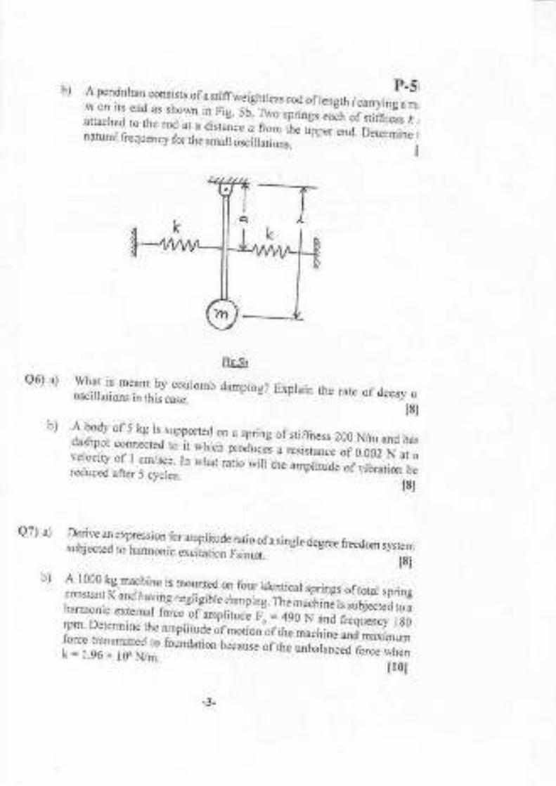
bl f ind lr.drls1lr tllletioo lbr thc systeft sho\r.ndiagram reduction rules.
P-511in ligure 4b. using hlock
18t
c cs)
fr5Lrre +- L>
SACTION . II
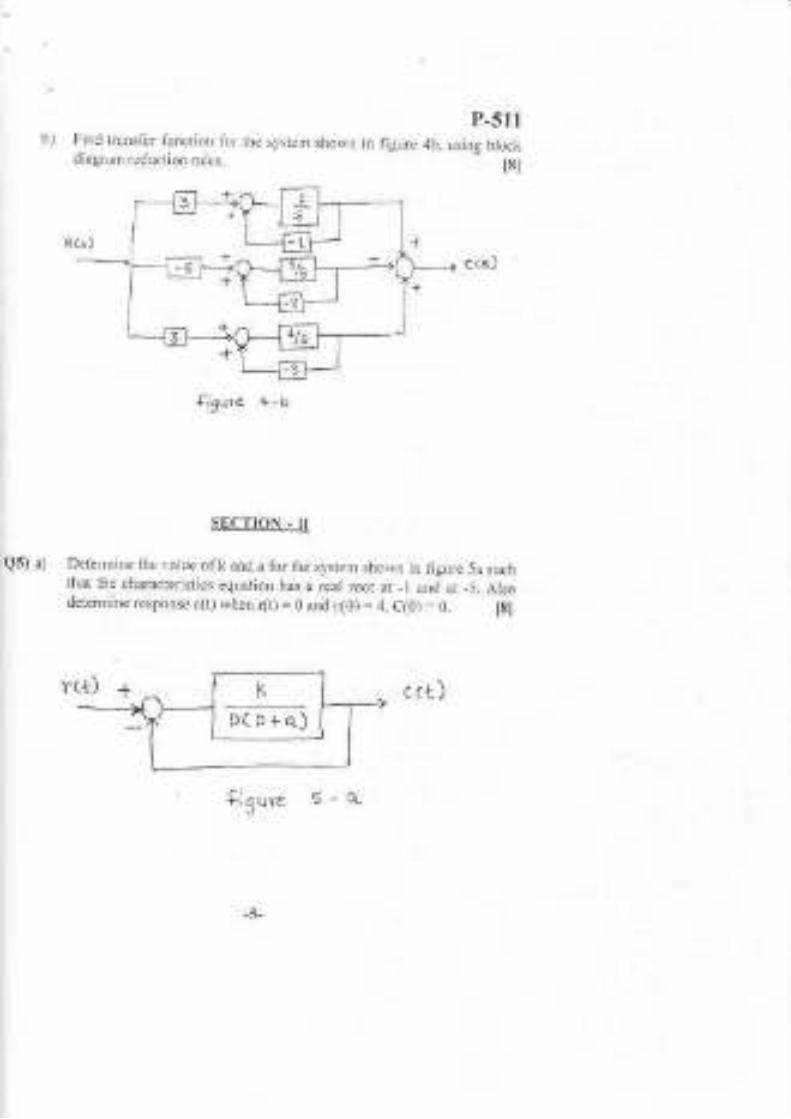
Q5) a) Determine rhe value ofk and a fb. the system shorvn in iigurc 5a suchthat the characteristics eqlration has a real root at _l ancl at -5. AIsodete.mile response c(t) wher (t) = 0 and c(0) : 4. C(0) : 0. ISI
c (t)
ti 3
uve 5-q
DtD+o.)

P-5ltbJ The opcn ioop tr:rnsfir l'unction ofunjty feedback systefl is givcn by
Kqf +rf4.syufr:x) find rangeofvalueofKsoLhatthecloscdslslenr
is absolutclv slahle.
Qb, al SLel(h Lhc roo'l,r.us turrlr( lLn,riL,,rC(5)H{S)= * -.. I,Ol' s(s r4s+B
)
b) Delermine damping ratio. pcak time and peak ovcrslloot lor lhe sJ,stenl
shou,n in iigr-rc 6b
l8l
t81
C(r)
Q7) a) Spced conl.ol s)'stem is desrribed by the dil'lirential equalion
2 (D+5)yrr) (D 2)(D 3)(D,4)'(" Dct''r'minu tlte''ntt'lulet'tliaglrm :rnd
state space representation by direct andparallel prog amrring method.lSl
I)etermine state space .eprcsertation lbr tlle syslen] shown in figure 7b. l8lb)
f.3u re 1- b
-6-

Qrt).,)
P-5llFind rcspofisc of{irst order ca)litrol s!stcm to unit iinPulsc and unit sicp
l'unction. \\ihcn all initial condiilons ar. /.cro.
b) llse llcneral proglamning 1() llod colnpulcr diaigran alld slale sPace modtl
_ .ls) _
uJth..s\.1.n,1,. r't: "n.1( n.tun R\\)(s+.r)
s(s 'r rs r8 )
IEI
I8t
o4IC,O4F]
-1-
. _<x-*0,q -
\:.fL'lY_--l
I) (1.t
Total No. of Pages :3Seat I
No.
Examination, April - 2016
THEORY OF MACI{INES-IISub. Code:66242
Day ard Date: Saturday, 30 - 0.1- 2016
Time:10.30 a.m. to 1.30 p.m,
Total Marhs :100
Instructions: 1) All questions arecompulsory2) Figures fo the rightindicate full lnarli.s.
3) Draw neat labelled sketches rylrerever necessary'.
4) Assume ifnecessary suitable dttt ard statc clearly.
. t Use ofNon proglanrmable (alculator is pcrmit(cd,
Q 1) a) Prove that tho condition lbr ;naximum efficiency in casc of spiral gear
o+0rvhere Q = friction angle, 0 : shaft angle and a= spiral
T.E.(Mechanical Engineering)(Part-I)(Semester -V)(Revisetl)
isd =
angle ou the dr-iving wheel. t8l
OR
Derive an expression lor minimum number ofteeth required on wheel to
avoid interlerence in mesh with gear.
b) Two mating involute gears of 20' pressure angle, number of teeth on
pinion 20, gear ratio 2, speed ofpinion 250 rpn.r, module 12 mm. Ift1eaddendum of each wheel is such that the path of approach and path olrecess on each side are halfthe maximum possible length each, find
i) addendum for both the wheels,
ii) length of arc ofcontact.
Q2)at Explain tJre worl<ing ofDj flelenrial gear o fan au tomobile.
OR
[10]
t61
P7:O.

P -512Motor shaft A exefis a constant lorque and is geared to shaft B. The
speed of shaft B is G times the speed of motor. Show that the angular
acceleration of{re shaft B is maximumvrh"n G=r(Io/Iu,; *h"t",Io
al:ld IB are the total lnass monents ofinerlia ofrevoiving parts attached
ro Lhe respeclive slLafts.
An epicyclic trailr ofgears is ananged as shown in fig. 2b. How many
revolutions does the am, to which the pinions B and C are attached,
make: [10]
it When A makes onc lcvolution ciock$ile and D makes lralI a
revol ution articlocku ise,
ii) When A makes one revolution cloclor,,ise and D is stationary? The
number ofteeth on the gear-s A and D are 40 ald 90 respectively.
Fig.No.2b
Q3) a) Explain the effect ofgyroscopic couple on ship during steering,pitching
t6Iand rolling.
b) Each road wheel of a ruotor cycle has a mass moment ofhertia 1.5 kg-
m2. The rotating parts of the engine of the tnotor cycle have a mass
moment ofinertia of0.25kg-tr':. The speed ofthe engine is 5 times the
speed of the wheels and is in t.1re same sense.The mass of the raotor
cycle with its rider is 250kg and its center ofgravif is 0.6m above the
ground level. Find the angle ofwheel ifthe motol cycle is travelling at
501ca per irour a4.d is laking a turn of 30 m radius. Wheel diameter is
0.6 m. [10]
b)

Qa) a)
b)
shaft when inclination to imer dead centre is 3 0''
Q5) a) Explain why reciprocating masses are paltiallybalaaced'
OR
b)
aO ")
b)
<> <> <tr
P-572Explain different 5,pes of dyramic forces acting in single slider crark
chailmechanism. t6lOR
What conditions are to batisfied Ibr a sl stcm to be dynamically equir alent
to a given system.
Connecting rod of a gas engine has mass of 70kg ald has a radius of
gyr ation oi3 6 cm, about a-ris through the centre ofgravity The length of
tt.,e rod between centres is 100 cm and the cenhe of graviry is 33 cm
Aom t1.re crark pin centre. Iftl.re cr.ank length is 22 5 cm and revolves at
a ur.riform speed of270 rpm. Determine the magnitude and the direction
ofthe iaertia force on the rod and the corresponding torque on the cranh
[10]
t6l
Explafu the balancir:rg of several masses rotating in same plane'
A five cylinrier il-line engine iunning at 750 rpm has successive cranks
144" apart, the distance belween the c1'linder lines being 375 T-' fr:pirtorrit'ot
" is 2Z5rtrr, a;d the ratio the comecting rod to the cralk
iength is 4. Examine the engine for balance of primary anri secotdaia
forJes ard couples and find theil maximum values' The reciprocating
mass for each cylinder is 15kg. Uzl
Explair maximum fl uctuatiorr of energy and coefficient of fluatuation-ol
erergy. 16I
The tumirg moment diagram for a petrol engine is drawn to the following
."al"r, T*iing -omentlmm:5 N-m, crank angle 1mm: l" The tuming
-o*"rrt aiugr-a- t"peats ltse1f at every halfrevolution ofthe enline and
the areas abire and below the mean tuming moment line taken in order'are
2g5 , 685, 40,34A,960, 270 mm'?. The lotathg parls axe equivalent to a
mass of 3 6kg at a radius of gyration of 1 5 0 rnm' Determine the coeflicient
offluctuatiir ofspeed when the engine runs at 1800 rpm [10]

P-513Total No. ol Plges : 4
Seat
No,
Total Marks : 100
T.tr. (Mechanical) (Part-I[) (Semester-V)
Examination, MaY - 2016
HEAT AND MASS TRANSFER
Sub. Code: 66243
D|ry ard Date : Morda)', 02- 05 - 2016
Time : 10.30 a.m. to 1.30 p.m.
Instructions: I ) Ail qlestions aru compulsory.
2) Figure to the righl indicatts full marks.
3) ,A.ssunlc $uitalllc datr when ever nccessary and state it claarly.
;t) Use ofspecific calculators is permiffrd,
Ql) Solve Aly Three:
a) Delnc cdtical ladius olilsulation. Also derive the equation tbr cdiical
radius olinsulation for hollorv sphere. l6l
b) What are the modes ofmass transfer? Explain Ficks )arv oldiffusion.
t6l
c) Air at 90'C flows in a copper tube (h : 384 lVlnK) of 4 cm inner
diameter ard with 0.6 cr':r thick walls which are heated from the ontside
by waler at 125 "C. A scale of 0.3 cm thick is deposited on outer surface
ofthe t[be whosc tilermal conduclivity is L75 \l7mK. The air and watet
side heat transfer coefftcients are 221 and 3605 Wm'zK, respectivell'.
Find overall heat tuanst'er coefficient on lhe outside area basis. 16l
d) A steam pipe is covered with tr.vo layets of insulation. The innel layer
(h: 0. i 7 \l'/mK) is 3 Omm thick and the outer iayer (k:0.023 WmK) is
5Omm thick. The pipe is made ofsteel (k-58Wmk) and has inner diameter
and outer diameter of 160 and 170 mm, tcspectively. The temperature ofsaturated steam is 300'C and the arnbient air is at 50'C. llthe inside and
outside heat transier coeflicients ale 30 and 5.8 Wm'zK, resirectively',
t6t
PT.O,
calcuiate tlre rate ofheat loss per unit length ofpipe.

P-513Q2) Solve Any Two:
a) Explain Lumped heat capacity analysis. Also give the phl,sical significanceofBiotnumber
tSl
b) Steel ball bearings (k = 50 W,hK. L:: 1,1 x i0 j mr/s) having a diameterof40mm are heated to a tempeEture of650"C and then que.nched in atank ofoil at 55"C. Ifthe heat transfer coefficient betlveerlball bearingsand oil is i00 \v/mrK. Detennine the du.ation of time tile bearing muitrcmain in a oil to reach a tea.rperature oli200.C.
ISI
c) A plate 2 cor rhick and 2 cm rvjde js used to heat a fliricl at 30,C. Theheat geteratior rate inside the plate is 7 x 10⁶ Wmr. Detemine heattransfer coell'icientto maintain thetemperatLlre ofthe plate belory lg0"C.Take k for plate 26 WmK. Neglect heat losses from t)re edge ofplate.
l8l
Q.]) Sol\ e An) luo:
a) Explain the er.ror estimation oftemperature measurement inthemoweil.
I8lb) An oil filled thcrmometer well mado of a $tee ltubc (k: 55.g WmK), 120
nrttr lorg and 1.5 mm thick is instailed in a tube thlough which air. isflowing. 1he temperatue of air stream is measured uith the help ofthcrnometer placed in the r,vell. The surijrce heat tralrsfer coel.ficient ofthe air stream easlred with the help of a thermometer placed il] the\{ell. The surlice heat transfer coefficient li.om the air to the rvell is23.3 W,/m:K and the temperatl.re reco.clecl by the themlonletet.is gg,C.Estinate the measuremenl in error ancl the percentaue error if thetemperature at the base ofthe ualJ is 40.C. tg]
c) An aluminiun.r alloy fin (k = 200 WmK), 3.5 mm thick and 2.5cm longprotrudes from the rvall. The hase is at.l2U"C and rmbient dr.temoeratureis 30'C. The heat transfer coel1icicnt mr1, be raken as .il W.,m,K. l.indthe heat loss and fin elficienc1,, ifthe heat loss hom the lin tip is ,.gfigiUl..
t8l
-2-

P-51:Q4) Solve Any Three of the ibllol,ing:
Aralyze theproblem ofnatural convection by using dimensional analysir
techniquc.
b) Write a shorl note on thermal boundary Iayer.
[6
Is
c)
Q5) SolveAny Tlree ofthe following;
a) State and explain Kirchhoff's law.
b) Write a short note on Radiation sl.lape factor.
c) Tjle temperatur.e of a flame in the fumace is 1900 K. Find i
d)
Consider a design of nuclear reactor using lree convection of liqui<
bisnruth. The reactor core is constructed olparailel vertical plales of2nhigh and l.3nT widw Find the maximum possible heat dissipation lionboth side oleach plate ilthe sud'ace te perature olthe ptate is 950.(and lowest alLorvable bismuth tenperaturc is 350.C. Properties of bismuilare, p = 10030 kg/mr, Cp : 0. 15 kJ&g K, h = I 1.2 W/mK, p = 8.7 x 10-N sec/m:, p : I .3 x 10r 1/K. Use the correlatior Nu : 0.13 (Cr. pr)il
[6
501<g/minute ofivater is heatecl fiom 30"C to 50.C by passing through Ipipp of2 cm diameter which is maintai[ed at 100"C, flnd the length o
tlre pipe Iequired, the propedies ofwater are p : 965 kg/mr , Cp = 420(Jlkg K, k : 0.585 WmK, v : 0.33 x 10i m2lsec. []se the corre latiorNu = 0.023 Reo3. P/31 ls
t6l
I5t
t6l
Isl
d) lihe inner sphere ofa liquid oxygen conlainer is 3Ocm in cliameter anc
oLrter sphere is 36cnt in diameter, both splreres are having emissivity ol0.05. Dersrmine the hear t'akagc mte in ro the liquid oxygen cortainelwhich is at -l ti3'C.

P-513
)6) SolveAny Three ofthe following:
a) Derive the expression for LMT[) for counter llow heat exchanger' 16l
b) Wdte a shofi note on design considerations ofheat excharger' I5l
c) What do you mean by condensation? What are the types ofcondensalior?
Which rype ofcondensatior is prefened? Justify your answer [51
11) Draw the temperature dishibution for the following heat exchangers. [61
i) Condenser.
ii) Evaporator.
iii) Counter flow heat exchanger having equal heat capacities.
iv) Countet flow heat exchanger having effectiveness equal to unity.
laaaa
-4-

Seat
No.
P-515Total No. ol Pages : 4
T.E, (Mechanical) (Semester - V) Eevised)Examination, May - 2016
MANUFACTURING ENGINEERINGSub, Code : 66245
Day and Date : Saturdan 07-05-2016
Time: 9.30 a.m. to 1.30 p.m.
Instructions: l) All questionsare compulsory.
Total Marks : 100
2) Figur€s to right:ndicate full marks to lhe question.
3) Assume ifnec€ssary suitable data and state them clearly.
4) Use ofnon-programmable calculators is permissibl€.
Q1) Solve any two:
a) Explain the different types of chips formation with neat labeled
diagrams" t8l
What is machinabil ity. Explain various factors affecting machinability. [8]
Following observations were made during orthogonal cutting opemtion
of a diameter 50 mm M.S bar. Depth of cut : 1.2 rnm, cutting force =
1000 N, feed force = 300 N, spindle speed:240 r.p.m., feed = 0.2 mm./
rcv., chip thickness after cut:0.5 mm, rake angle: 120". t8l
Find out i) Shear plane angle
Cutting velocity, chip velocity and shearvelociry
Coefficient of friction between chip and tool.
Q2) Solve any two
a) Define tool life. Discuss various facto$ affecting tool life. I8l
P,T,O.
b)
c)
n)
in)

b)P-515
Draw tool geometry ofa milling cutter and explain nomenclatue in detail.
t8l
A carbide tool with mild steel workpiece was found to give a life of 2hours while cutting at 60 m/min. Cornpute the tool life ifthe same tool isused at a speed 30oZ higher than the previous one. Also determine thecutting speed for required tool life of 180 minutes. Assume Taylors
c)
Equation as VT o,e = Constant. 18l
Q3) The componentshown in fig. 1 is to be processed on a single spindle automat.Study the component and prepare: u8l
Material - / 25 polish brass bar
All dimensions are in mm. (Fig. noi to scale)
Detailed process sheet
Tool layout
Carn profile for drilling operation.
")
b)
c)

P-515
Q4) Solve any one
a) Design and drcw neat dimensional drarving in three views witi one
sectional view ofajig for drilling two holes of0l2 through as shown in
fig.4a. Show cleady the details ofclamping and location ofworkpiece.
Assume this as a final operation.
Fig,4a
b) Design and dmw a neat dimensional sketch in thrce views with one
sectional view ofa milling fixture formilling 3+ 0.05 mm wide slot at the
component as shown in fig.4b. Show the details of location, clamping
and cutter setting. Assume this as a final operation" 126l
Iz6t
Fig.4b
-3-

Q5) Solve any two
a) Wilh neat sketch wite down differenl types of dies.
c) Discuss design considerations fordie element.
Q6) X/rite Short notes on any tlree:
a) Work holding devices in CNC.
b) Automatic tool changers.
c) Automatic pallet changer.
d) Tool materials and tool geometry signature ofCNC.
+++
b) Find the total pressure, dimensions oftools to produce a washer 5cmoutside diameter with a 2.4 cm hole, from -"t*irf + ,rrn tf,i"[, irrlrg
"shear s&ength of360 N/mm2. 16l
P.515
l6l
t61
112'.1
-4-

P- 796Total No. ofPages i3Seat
No.
T.E.(Mechanical Engg.)(Part-I)(Semester -VXOld)Examination, May - 2016
METROLOGY AND QUALITY CONTROLSub. {lode: 45564
Day ard Date :Tuesday, 03 - 05 - 2016 Total Marks :100
Time :10.30 a.m, to 1.30 p.m,
Instructions: 1) Answer any three questions from each section.
2) Figures to the right indicate full marlis.
3) Drarv neat figurcs lyhcre\Icr nccessary,,[) Assurre suiteble data onlywherever necessary and state them clearly.
, 5) Useo{non-programmalrlecnlculatorisp€nnitted.
SEC?ION-I
Q1) a) Explaiu briefly classification, care and use ofslip gauge with the help offigures. t81
b) What is essential purpose fo a limit system? Explain three differenttypes
offits using ligures. t8l
Q2) a) Explain wilh neat sketch conshuction and working ofvemier caliper(81
b) Calculate the fundamental deviation and tolelances and hence the limits
ofsize for the shaft and holepair designated as 55 mmH;t.The tolerance
limit is given as.
i:0.45 :LD + 0.00lD Microns
The diameter steps are 50 mm and 80 mm. The tolerance grade for number 8
quality is 25i and for nunber T quality is 16i. I8l
Q3) a) Describe with neat sketch explain the measurement of concave and
convex surface radius. t81
b) Discuss the use of autocollimator,for checking flatness ofthe surface
pla1e. t81P.T.O.

Q4) Write short notes on any three
a) Line and end measurement.
b) Level beam comparator
c) Dial gauges
d) I{ole base sysrem and shafl base sistem
e) Clinomete$.
P -796
[181
SECTION.II
Q5) a) Describe the constnrction ancl working of any one instrument used in
suface finish measurement. tSl
b)
4
b)
Describe diflerent erors occured in a screw tlread
Explain Parkinson's gear tester with sketch.
t81
t81a6)
Q7) a)
b)
What do you know by cost of quality and va.lue of quality? How to
balancethem? t8]
Explain operaring characteristic curves with neal skelch. l8l
Table given below shows number of defectives found in inspection ofa1ot for 1 00 pJugs each.plot a P chart and check a process is in control or
not. t8t
Lot Number l 2 4 5 6 7 8 9 t0
Number of
defectives
6 3 4 3 0 tl 5 2 3

P -796
Q8) Write short notes on any tfuee I18l
a) Objectives of qualitY control'
b) x chafi
c) Variable inspection and attritule inspection
d) Sampling inspection & percentag€ inspection
e) AWQL and L|PD
-3-

Seat
No.
P.838Total No. of Pages : 4
b)
ofE and T, when Q. * E .
Total Marks : 100
t6l
Fig.lb
T.E. (Mech.) (Semester - Y) (Reviserl)
Examination, April - 2016
CONTROLENGINEERING
Sub. Code : 6624I
Day ard Date i Friday, 29 - 04 - 2016
Time | 10.30 a.m. to 1.30 p,m.
Instructions: 1) All que$ions are compulsory,
2) Assume suitablc data wherever required and mention it clearly,3) Figures to rightiDdicate f$ll marks.
Ql) a) Construct gounded chair representation lor the mechanical system shownin fig. 1a and draw electrical network using direct analog. 16l
r' Pc f- a'
Fis 1 o-
For the thermal system, shown in fig.1 b, find equation ofTas a function
P.no.

P-831
c) For the gear t ain shown in fig. 1c, derive equation between motortorqu
(T.) and load torque (T,-). 16
JNl
hBr
Jr. B1 _Lfl-lt\
9r
Nr-I oodt-_l. Br.
F;3. L
Q2) a) For a sonic flow of air through a restriction, the mass flow rate
TM
1;
fvf = ffi . e.e *fr.re M is mass flow rate, T is inlet temperature, A
area of restriction and P is the inlet pressue. Detemine
approximation for M when area A is held constant.
C(S)
b) Reduce the block diagram sho\an in Fig, 2b and iind R6t
the liner
lr
Jr
ccs)
Fig r u
-2-

P_83Q3) a) Pole zero configuration of the overall transfer function is shown in Fi1
3a. Determine its response for unjt step input. tS
Real qrig
f'3'34b) The step response ofa second order control system is shown in figure
3b. Determine the closed loop transfer function ofthe system, [glc (i)
2.5
2-
a
Ft,3b
-3-

P_838Q4) a) Using Rouths stability criredon, determine the stability ofsystem having
its open loop transfer function has poles at S = 0, S = -1, S = _3 and
(s+r+ 76)(s+r-i."6)
l6l
110I
zero at S: -5. Take gain K = 10.
b) Sketch root locus for G(S) .H(S) =K(s + 2)
e5) a) Draw bod. otot ro, es)=ffis+s)
b) Determine the computer diagmm and state space representation for thesystem shown in fig. 5b, using direct programming.
ISI
u0l
+(r) u (r)
ffg' s b
Q6) a) The working ofa speed control system is described by the differentialeq".
t8l
. . 2(D+5 t
x1)=-,----- - .J(r)' (D+2) (D+3) @+4J
Determifle state space repfeseltation and computer diagfam by generalprograrruning.
b) For a uniry feedback sysrem wirl CtSr=I(S1!lS +4.S+5 t8I
Find:
i) angle ofdeparture for complex poles.
ii) enky point for the root locus as it enterc the real axis.
f,rff
-1-

s - 2082Total No. of Pages : 3Seat
T.E. (Mechanical) (Semester - V) (Revised) Examination,
December - 2015
THEORY OFMACHINES - IISub. Code : 45549
Day and Date : Tuesday,08 - 12 - 2015
Time : 02.30 p.m. to 05.30 p.m.
Total Marks : 100
Instructions : 1) Attempt any three questions from each Section.
2) Figures to the right indicate full marks.3) Make suitable assumptions ifnecessary ard state them clearly,
SECTION . I
Ql) a) Denvelhe equation for maximum efficiency ofspiral gears. l7lb) The centre distance between two meshing spiral gears is 150 mm and the
angle between the shafts is 60". The gear ratio is 2 and the normal circularpitch is l0 mm. The driven gear has a helix o125".
Determine :
i) The number ofteeth on each wheel.
ii) Exact centre distance
iii) efhciency iffriction angle is 4".
Ie1
Q2) a) Wrrte a note on torques in epicyclic gear trains t61
b) An epicyclic gear train is as shown in fig - 1, the input I tums at 180
r.p.m. counter clockwise, the input 2 tums at 720 r.p.m. clockwise.Determine the speed and direction ofrotation ofthe out put shaft. The
number ofteeth on gears are
To = 20, T, :32,Tc: 48,TD:24,TE:36 and T.: 108. [101
P.T.O.

-I
s -2082Q3) a) Ashaft canies four A, B, C, D ofmagnitude 200 kg, 300 kg, 400 kg, 200
kg respectively at radii 80 mm, 70 mm, 60 mm and 80 mm in planes
measured from A at 300 mrn,400 mm, and 700 mm. The angles between
the cranks measured anti clockwise are A to B 45', B to C 70" and C to
D 120". The balancing masses are to be placed in planes X and Y The
distance between the planes A and X is 100 mm betrveen X and Y is 400
mm and between Y and D is 200 mm. Ifthe balancing masses revolve at
a radius of 100 mm find their magnitudes and angular positions. [121
b) Explain balancing ofV engine. t6l
Q4) a) Explainthe terminology ofgl.roscope and method offinding g1'roscopic
effect. t61
b) A rear engine automobile is travelling along a track of 100 m mean radius
each of four wheels has Moment of Inertia of 1 .5 kg-m'? and effective
diameter of 60 cm. Rotating parts of engine have M.l. of I kg-m']. The
engine axis is parallel to rear axle and crank rotates in same sense as road
wheels. The back axle ratio is 3:1. The vehicle mass is 1000 kg. and has
a C.G 40 cm. above ground level. Width of track of vehicle is 1.5 m.
Determine iimiting speed of vehicle round the curve for all four
wheels to maintain contact with road surface ifthis is not cambered.[01
SECTION - II
85) a) What are the gereral causes of \4bration? Explain the desirable and
undesirable effects ofVibration. 16l
b) A cylinder ofmass M and radius r rolls without slipping on a cylindrical
surface of radius R. Find the natural frequelcy for small oscillations
about the lowest point. tl0l
Q6) a) Derive that the loss ofamplitude per cycle for coulomb damping is given
by 4FlK, where F is the frictional lorce and K is Spring stiffness. t8l
b) A 25 kg mass is resting on a spring of4900 N/m and dashpot of 147 N-sec/m
in parallel. If a velociry of 0.10 m/sec applied to the mass at the rest
position, what will be its displacement from the equilibrium position at
the end ofthe first second?
_', _
t8l

s - 2082
Q7) a) What are the types of forcing functions commonly encountered inengineering practice? Derive the equation for steady state response ofsingle degree freedom system consisting ofmass M.Spring Stiffness Kand damping coefficient C subjectcd to constant harmonic excitation
F=Fosi n tot. t8l
b) A machine ofmass I tonne is acted upon by an extemal force of2450 Nat a frequency of 1500 rpm. To redtrce the effects ofVibration, isolator
ofrubber having static deflection 2 mm under the machine load and an
estimated damping coeffrcient 0.2 are used.
Determine:
i) force transmitted to foundation
ii) amplitude ofvibration, and
iii) phase lag.
t8l
Q8) a)
b)
Derive the expr€ssion for steady state response ofa single degree freedom
system involving rotating unbalance. t8l
A disc ofmass 4 kg is mounted midway between bearings which may be
assumed to be simple supports. The bearing span is 50 cm. The steel
shaft is of l0 mm diameter and is horizontal. The centre ofgravity ofthedisc is displaced 2 mm from the geometric centre. The equivalent viscous
damping at the centre ofthe disc-shaft may be assumed as 50 N-sec/m.
If the shaft rotates at 250 rpm, determine the maximum stress in the
shaft. Also find the power required to drive the shaft, at this speed. Take
E = 1.96 x 10rrN/m2. t10l
*r()k
-3-
s-2083Total No. ofPages : 3Seat
No.
T.E. (Mechanical) (Part - III) (Semester - \r) Examination,
December - 2015
HEAT & MASS TRANSFER
Sub. Code : 45550
Day and Date : Thursday, l0 - 12 - 2015
Time:02.30 p.m. to 05.30 p.m.
Total Marks : 100
Instructions i 1) Solve any three questions {rom scction I and section II cach.
2) Assume suitable data ifnecessary.
3) Figures to right indicate full marks.
QL) a)
b)
SECTION - I
Define thermal conductivity and discuss thelTnal conductivity for solids,
liquids and gases. t6l
Q2) a)
A square plate heater (size 20 cm x 20 cm) is inserted between two
slabs. Slab A is 2 cm thick (k = 45 w/mk) and slab B is 0.01 m thick(k = 0.2 w/mk). The outside heat transfer coefficient on both sides ofA and B are 180 and 50 w/m'?k respectively. Temperature ofsurrounding air is 25'C. If the rating of heater is 1.2 kW. Find. [10]
i) Maximum temperature in the system.
ii) Outer surface temperature of two slabs.
Draw equivalent circuit for system..
A 10 cm OD pipe carrying saturated steam at a temperature of 195'C
is Iagged to 20 cm diameter with nlagnesia (k = 0.07 w/mk) and further
lagged with laminated asbestos (k = 0.082 rv/mk) to 25 cm diameter.
If the surronnding air lemperature is 15"C and heat transfer coelficient
is 20 w/m':k find the mass of steam condensed in 8 lus in a 100 m
length of pipe. Inside heat transfer coefficient is 75 w/in'zk. Neglect
thermal rcsistance of pipe Daterial. (Latent heat of evaporation =
t8l
P.T.O.
1951 kJ/kg),
-I
s-2083b) A hollow cylinder 6 cm ID, 9 cm OD has a heat generation rate of
5 x 10 kdmr. Inner surface is maintained at 450pC and outer surface is. at 350'C Thermal conductivity of material is 3 w/mk. Determine. [10]
i) Value and location of maximum temperature.
ii) Temperatre at midthickness of cylinder.
iii) Sketch the temperature profile.
Q3) a)
b)
Ql) a)
b)
Qs) a)
b)
Derive the expression for temperature distribution in a flnlength with insulated end.
Define fbllowing terms :
i) Em.issive power
iii) Iradiation
of finite
t8l
t8lii) Emissivity
iv) Radiosity
Show that the total emissive porver of a black surface is equal to IItimes the intensiry of radiarion. t8lA 10 mm OD pipe carries a cryogenic f'luid at 80 K. This pipe isencased by another pipe of 15 mn OD and the space between the pipe
is evacuated. The outer pipe is at 280 K. Emissivities of inner and
outer surfaces are 0.2 and 0.3 respectively. Determine the radianr heat
flow rate over a pipe length of 5m. t8t
SECTION . II
What are the natural convection flow patterns? Explain by drawingneat sketches. tslCalculate the rate of heat loss by Iratulal conyection trom a outside
surface of a verlical pipe of l0 cm outside diameter and 3 m long. Thepipe has outside surface temperature o{ 100t and surroundhrg air at
20'c. t8lUse suitable relation lrom :
Nu = 0.1 (Gr.pr)'/3 for 10e < Gr. pr < l0i2
and Nu = 0.59 (Gr.pr)o'?s for 10a < Gr.Pr <10e
The properties of air at 6ffC :Lre :
n = 0.696; k = 0.02896 rvlm.k; y= 18.97 x 10jm,/s

Q6) a)
b)
s-2083
Discuss 'Dimensional Analysis' as a tool in forced convection toevaluate convective heat transfer coefficient. t8l
A motor cycle cylinder consists of 10 fins, each 15 cm outside diameter
and 7.5 cm inside diameter. Calculate the rate of heat dissipation from
the cylinder fins rvhen the motor cycle is running at 60 km,/hr. Use
Nu = 0.036 (Re)or, (Pr)o !. t8l
The atmospheric air is at 20'C & the average fin temperature is 480'C.
The thermophysical properties at average temperahlre of 250'C are :
p = 0.674 kg/mr: Cp = 1038 J/kg.k, k = 0.0427 w/mk;Pr=0.677; T=40.61 x 10{ m2ls
The approximate value ofheat transt'er coefficicnt may be evaltated
by considering the fins as a single horizontal flat plate of the same area.
Take the characteristic lergth 'y' = (0.9 x d).
Q7) a) Derive ar expression for ef1'ectiveness of parallel flow heat exchanger.
t8l
b) The following data is given for counter flow heat exchanger : [8]
mr = 1.0 kg/s; m. = 0.25 kg/s; Cph = 1.(X5 kJ/kg.'C;
Cpc = 4.18 kJ/kg. "C; Thi = l000"Cl Tco = 850'C; U = 88.5 w/mr.t&A=i0nf.Calculate 'Tho & 'Tci'. Take e = 0.48.
Q8) Write shoft notes on (Any Three)
a) Hydrodynamic & thermal boundary layer,
b) Reynold's analogy tbr laminar flow.
c) Combined free & forced convection.
d) Typical pool boiling curve.
e) Fouling f'actor.
i) Modes of mass transfer.
t18l
***
-3-

Seat
No.
s-2084Total No. ofPages : 3
T.E. (Mechanical Engineering) (Semester - V) (Revised)
Examination, December - 2015
MANUFACTURING ENGINEERING (NCw)
Suh. Code : 45565
Total Marks : 100Day and Date i Saturday,l2 - 12 - 2015
Time : 02.00 p,m. to 06.00 p,m.
Instructions : 1)
2)
3)
4)
s)
Question No. 1 and QuestionNo. S are compulsory.
Solye two questions from remair ng questiofls ofeach section.
Figure. to tbe right indicale full marks.
Assume suitable data wherever necessary and statc it clearly.
Use ofnon programmable calculator is allowed.
SECTION - I
Q,l) The component shown in Fig. 1 is to be processed on a single spindle automat.
Study the component and prepare
i) Detailed process sheet
ii) Tool Layout
iii) Cam profile for drilling operation
iv) Calculate production rate per hour.
t18l
cll lx45'
,"-*'
Materlal: BrE6sO20 BarAll dimebionr !rc iD mm
Fi8. I
P.T,O.

t8l
chip thickness t = 0.3 mm, Feed = 1.8 mm /rev
Width of cut b = 2.5 mm
Rakeanglea-10'
Cutting force Fc = 1200 N
Feed force Ff = 300 N
Determine
i) Shear angle
ii) Co-eff. Of fiiction at tool chip interface
iii) Shear stress
Q3) a) Using Taylor's equation and using n = 0.5 and C = 400. Calculate the
percentage increase in tool life when the cutting speed is reduced by50Vo. t6l
b) Define machinability. What are the factors affecting machinability?
Establish machinabiliry based on t10l
i) Cutting force ii) Surface finish
Q2) a)
b)
Qa) a)
b)
s-2084
Derive an expression for shear angle. State clearly the assumptions made.
t8j
In an ofihogonal cutting operation the followed data have been observed :
Explain with neat sketch the tool geometry of single point cutting tool.
t8l
Explain heat generation in metal cutting and significance of use ofcoolants. t8l
SECTION - II
Q5) Design and draw neat dimensional drawing in three views with one sectional
view of ajig for drilling two holes {10 as shown in fig.Il. Show clearly the
details of location, clamping and guiding elements. Assume this as a finaloperation.
-)-
1261

: s-2084OR
Design and draw neat dimensional drawing in three views with one sectional
view of a milling fixture for milling the 10 t 0.05 mm wide slot at the
component shown in fig.Il Show the details of location, clamping and
setting of cutter. Assume this as a final operation. t26l
flG{l
Explain the importance of following in press working.Q6) a)
b)
i) Strippers n) Clearance
Explain with neat sketch progressive die.
t6l
t6l
Q7) a) List the basic methods for replacement and selection of the tools and
explain any one method. I6l
b) Explain breakeven point method for selection of machine tools. 16I
QB) Wnte short notes or any two.
a) Methods of estimation.
b) Advantages of using jig and fixtures.
c) Diamond locator.
d) Stdp layout.
Itzl
*#*-J-

s-2085Total No. ofPages | 7Seat
No. I
T.E. (Mechanical) (Part - III) (Semester - Y) Examination,December - 2015
MACIIINE DESIGN - ISub. Code: 45551
Da) atrd Datc : Tuesdal', 15 - 12 - 2015
Time: 02.30 p.m. to 05.30 p.m.
Instructions i l) Attempt s[y three questions from each scction.
2) Figurcs to th€ rightindicatcs full marks.
3) Draw sketches ifrequired.
4) Assume suitable data & mention thesame clearly.
Total Marks : 100
SECTION - I
QI) a) Give general design procedure for a Machine component. t6l
b) Recommend suitable material for following components with reasons.
t6l
i) Surgicallnstruments
ii) Keys lor Fastening.
iii) Helical spring
c) Enlist different theories of Failure. Explain Maximum principal(Normal) stress theory. t51
Q2) u) Explain design procedure of turn buckle. Ulb) Design a right angled bell crank lever. The horizontal arm is 500 mm
long and a load of 5 kN acts vertically downward at the end of this
arm. A short arm is 100 mm on which force acts. The permissible
stresses for lever and pin materials are 75 MPa intension and 60 MPa
in shear. Safe bearing pressure is 10 N/mm'z. The lever has rectangular
cross-section and ratio of width to thickness is 3: l. The pin length is
t10l
PTO.
1.25 times pin diameter.

Qs) a)
b)
Qa) ")
b)
Qs) a)
b)
s-2085
Explain design procedure of bolted joins subjected to eccentric load
in shear. t8l
A 50 mm diameter solid shaft is welded to a flat plate as shown inFig. I. If size of the weld is 15 mm. Find the maximum normal and
shear stress in Weld. Refer Sketch. t8l
Fst
Explain design procedure of rigid flange compling with neat sketch.
tel
A steel spindle ffansmits 6 kw at 1200 rprn. The angular deflection
should not exceed 0.25" per meter of the spindle. If the modulus ofrigidity for the material of spindle is 85 GPa. Find the diameter of the
spindle and the shear stress induced in spindle. t7'1
SECTION - II
Explain Wahl factor and it's use in spring design. t6l
Safety value of 50 mm diameter is to blow off at pressure of 1.2 Nimm'?.
It is held on seat by helical spring of spring index 5. Maximum lift ofvalue is 5 nm. If maximum shear stress limited to 420 N/mm'z and
modules of rigidity 84 x 103 N/mm'?. Design spring.
Ref'er table for wire selection
u0l
SWG 4t0 3t0 2t0 0 1
Wire dia mm 10.160 9 .490 8.839 8.229 7 .620
;i

Q6) a)
b)
Q7) a)
b)
Draw sketch of recirculating ball
application.
s-208s
screw explain it's r.r,orking and
t6l
A double start square threaded screw of 80 mm nominal diameter rvith
10 rnm pitch, supports vertical load of 20 kN. Axial thrust on scrcrv is
taken by collar bearing of 200 rur outer di:rmeter and 150 mrl itner
diameter. [10]
Find force required at end of level u,hich is 300 mm long to raise
and lower load.
Coefficient of friction for screw is 0.15 and fol collar 0.2.
Explain coefficient ol fluctuation of speed indicating various r,alues o1'
applications. I7l
The turning moment diagram of multicylindq cnginc is drawn with
scale 1 mm = 4.5" on X axis and I mm = 70 N.m on Y axis, The
intercepted areas between torque developcd by cngile and mean
resisting torque of machine taken in order fron.r are -35, +410, *285,
+325, -335, +260, 365, +285, -260 mm2. 'lhe engine is running at
mean speed of 300 RPM. Coefficient of speed fluctuatiotr is limiled to
0.02. Rimmed flywheel is malde from grey C.L (FG 200) with mass
density 7100 kg/m'. Hub and spokcs contributes l0% of required.
Moment of inertia. 'llhe rim has recti:rngular cross section with width to
thickness ratio 1.5. Find dimensions of rim. t10l
Q8) a) Give various steps to select flat belt liom ntanufactuter's catalogtLe. [7]
b) Select V belt to connect l5 kw@ 1500 RPM to comprcssor running at
500 RPM centre to centle distance bctween sha1ls is approximatly 1m.
Machine is running at l0 Hrs/day. l10l
Select belt specifications, number of belts. correct cenlre distance
and pulley diameters.
--t-

s-2085
D.ta forO.No.8(b)
Poter rsdng of V-heltJ
(o. = I 80" ; speld oi the faster puliey - 1440 r p m.)
(D = pulley drameGr (r,m) ; P,R = Power raling in kW)
Ddigtr povrr ftW)
Selection of cross section of V-belt
secrioo i D 75 80 E5 90 100 106 112 118 125
A I m 0.73 0.36 0.99 r.12 r.38 1.50 1.63 1.81 2.00
125 132 140
2.24 X.46 2.77
200 212 224
6.14 6.61 7.68
350 3r5 400
t5.? li.5 i9.3
1?0 r80 190 200
4,0a 439 4.1',[ 5.23
265 280 300 315
10.10 11.1012.10 12.50
-4-

s-2085
Conection factor ({) for indusural senice
Operational hours per day
Type of service
0 -r0 10-16 16-24
1) Liglt dutyi ag.itators-blowers-cenldfugal
pumps fans (up to 7,5 kW) and comFe.ssors
?) Medium duty: coneyon-fans (above 7,5 kW)
lirc shafu mechirc tools-pesses ad positive
displacenent fllmps,
3) HearT. dury; conveyors-bucket elevaton ald
huoEers
i.t
1.2 1.3
1.3 t,4
1.3
1.4
1,5
1,2
tcr!*Irr
En,t o.r
,. tto tlo ttq ltutt d
Conection factfi for arc of cotrtact (V-$oov$ on both pulleys)
l'or 'v' belts
Saies of prifened values for pltch diameteN (in nuo) are ar follows:
Pitch diameter (r'io) : 125 132
200 zrz 224 236 2s0
400 425 450 4?5 500
750 800 900 1000
1?0 180 190
315 355 375
630 670. 710
140 150
265 280
530 560
160
300
600
-5-

r
s-208s
Dimensions of staadud cross-sections
Belt Section Width Thickness Minimum pirch
W(rm) lr(mn) dianeter of puuey (mm)
B
C
D
E
13 8
l1t7
125
200
300
500
630
22 t4
'32 t9
.38 21
ConYersion of inside lcngth to pitch lcnglh of Se belr
Belt Section
Difference between pi:ch lengh
aud i$ide length (run) 36 43 56 79 92
A BCDE
-6-

s-2085
Coneclion laclor F, for b€lt longth
(lr - nominal inside leogth of the belt in om)
Bqh seclioll
1m5
1!n1
2032
2A57
2N?A1a
2ML\40
267
28l'5
30"t8 1.13
1.14
3150
3/5L
3404
o.%
0.87
t.o2
1.03
1.04
1.04
1.05
1.06
1.08
o.n
0.98
o.98
0.99
1.00
7.02
1.03
1.04 -
1.05
1.07
1.08
0.87
-0-89
0.90
0.91
0.92
0.94
o.ss
o.97
0.91
0.98
0.99
1.to
.t.rt-
3d58
4013
4115
4394
4512
4953
5334
6045
6W7569
1.11
r.13
1.14
1.15
1.16
1.18
1.19
1.00
1.02
1.03
r:04
1.05
1.07
1.08
1.11
1.14
1.16
0.90
o.tz
o,92
0.93
0.94
0.96
1.00
1.03
1.05
0.96 0.94
0.96
0.99
1.01
***
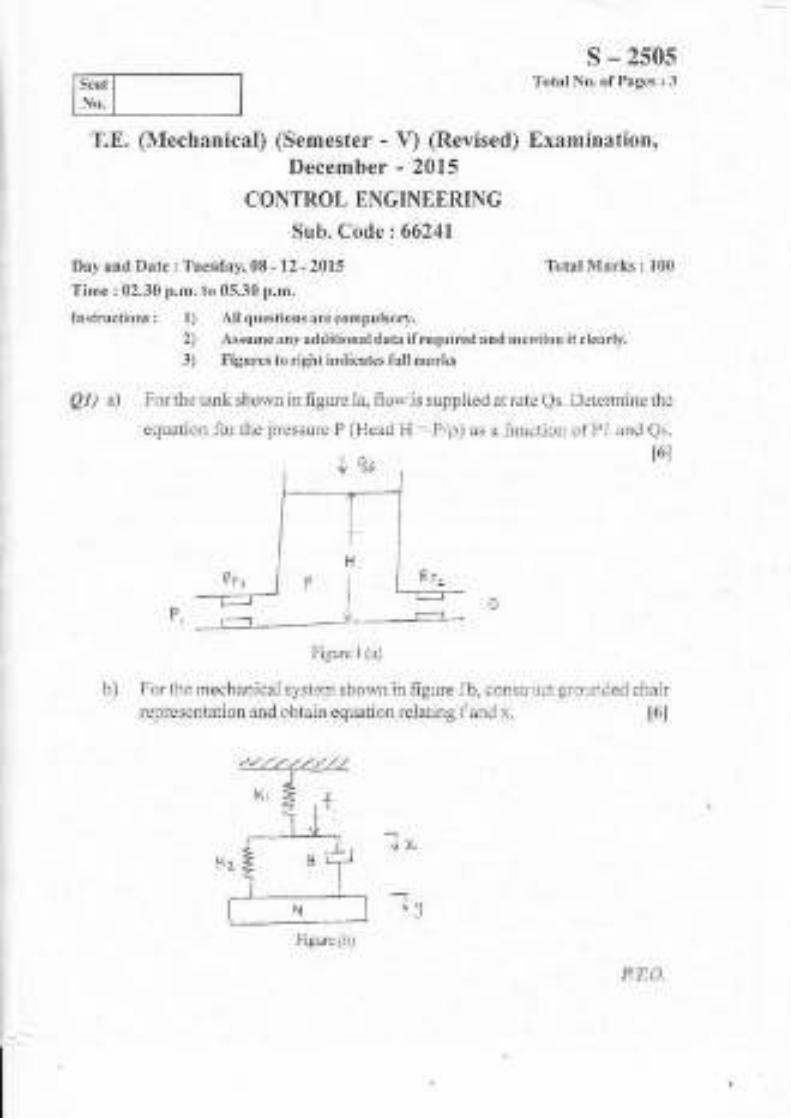
s - 2s0sTotal No. ofPagcs i 3Seat
No.
December - 2015
CONTROL ENGINEERING
Sub. Code : 66241
Day and l)ate : Tuesday, 08 - 12 - 2015
Time : 02.30 p.m. to 05.30 p.m.
Inst'rxctions : 1) All questions arc compulsory.
Total Marks : 100
2) Assume any additioual data ifrequired and mcntion it clcarl].
3) Figures to right indicates full marl{s
81) a) Iror the tank shown in figure la, flowis supplied at rate Qs. Detennine thc
equation for the iressule P (Head H : P/p) as a function ol P I and Qs.
l6l
T,E. (Mechanical) (Semester - V) (Revised) Examination,
P,
Figure I (a)
b) For the mechanical sysiern shown in figure 1b, construct grounded chair
representation and obtain equation relating fand x. i6l
-J.
-tJ
Figure (b)
P?:{}.

c) For the elcctlical nctrvork shown in figure
system using invcrsc analog,
s - 25051,1c conslruct mcchanical
t6l
T
IFigure 1.1(c)
OR
Obtain rnalhcmatical nrodcl for gear train.
Q2) a) The equation fbr the area of the parallelogram isA= W.L.sin0. Determine
the linear apploximation for the area A. For Wi = 1 2, Li = 8 and 0i = 60',
what is th.e approximate area ofAwhen W= 14, L = 9 and 0 = 58". [8]
Reduce the block diagram shown in figure 2b and find transfer function [8]
ccs)
83) a) Forthe system shown in hgure 3a, determine the value ofK suchthatthe
damping ratio is 0.5. Then obtain rise time, peaktime, ma.rimum overshoot
and setting time. 18l
t6l
R(J) r c<s)
Figue 2 (b)
Figurc 3 ta)

s - 250sb) Fol thc spring, mass, dampcr systcm shown in hgurc 3b, obtain response
whcnx(0)=0,i(0)=1,1=0,M:1,I1:3andK:2. I8l
+
-l v-
K(S':+8S+25)Q4) a) For the lirnction G(S) H(S) =
all relevant details.
construct root locus with(S + 1)(S+s)
tl2lb) The characteristics equation offeedback control system is Sr + 2053+
15S'?+ 2S + K = 0, detemine the range ofK for the system to be stable-
t6I
Q5) a) Draw Bode p
G(s) H(s) =
b)
Q6) a)
lot for the transfer fi.mction
50
S(S + 0.25SX1+ 0.15)
i) Gain margin
ii) Phase margin
Write a short not on Polar plot.
From the graph determine. [8]
t8l
For the differential equation (D + 3) (D + 4) y(t) = (D + 6) (t), construct
computer diagram and state space representation using directprograrurunS. 18l
b) Construct computer diagram and state space representation using general
programming for system represented by differential equation (D + 2)
(D + 5) y(t) = (D'?+ 3D + l0) f(t). t8t
aoo-3-
Figure 3 (b)

s - 2506
Totat No. of Pages : ,lSeat
No. I
CONTROL ENGINEERING (Pre Revised)
Sub" Code :48709Day and Date : Thursday,ll - 12 - 2015
Time : 02.30 p.m. to 05.30 p.m.
Total Marks : 100
Instructions: 1) Attempt any three questions from section - I and section . II'2) Assume ary additional data if required and mention it clearly.
3) Figures to the right indicates full marks
SECTION- I
Ql) u) Construct mechanical systemusing force voltage analog for the electrical
T.E. (Mechanical) (Semester - \) Examination, December - 2015
network shown in fisure la. l6l
tri gur e' L-e-
b) Explain torsional system with neat sketch and write equation between
torque and angular displacement. t6l
c) Draw fiee body diagram and write the differential equations ofthe system
shown in figure lc. t6l
IiSore i,- bc
P.T.O.

Q2) a)
s - 2s06
nLinearise the equation V = - , whete V is velocity, D is displacement
and T is time. Determine the linear approximation forv due to change ind and change in t. t8l
Reduce the block diagram shown in figure 2 b and find hansfer function.[8]
Q3) u) A controller is to be designed for a system such that the output c will not
change by more than I unit when the load changes by l0 units. The
steady state operating curves for the system to be controlled have a
slope of 5 units. What is the required slope of the controller Iines
whenB=-0.3 t8t
b) For the system shown in figure 3 b, determine K, zutd K, so that the
system will have a steady state gain of I and a time constant of 0.5
sec.
c cu)
b)
t81
Q4) a)
b)
With neat sketch, explain the operation of hydraulic servomotor and
determine the overall block diagram representation. t81
Derive transfer function relation for AC and DC tachometers. t8l
fig(lle a-b
€ i5r.rre 3 - b
-2-

s - 2s06
SEqTION. IIQ5) a) The block diagram ofa unity feedback control system is shown in figure
5 a. Draw the root locus diagram for the control system. 172l
R(5) f---------) ccs)
Q6) a)
Q7) a)
b)
f igure 5-o"
b) The characteristics equation for certain system is (s4 + 45, + 35 + K) = 0.
Determine the value ofK for marginal stability, Also find the frequencyvalue above which system becomes unstable. I6I
Obtain unit step response of a unity feedback system having an open
4Ioop transler funcrion G(S) ;;;-:; Consider all initial conditions asJ(J f ))
zero. t8j
For the system shown in figure 6 b, determine damping ratio and naturalffequency, ifthe time constant T is 3 sec and ratio of torque to inertia(Kll) is 219 ra&lsec,. t8I
<< s)
{igure 6 - 6
For the series RLC circuit shown in figure 7 a, determine the equationfor damping ratio and natural frequency. t8l
f ig.\.- i <!
-3-
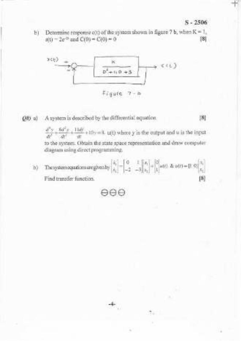
fl
QB) a)
s - 2s06
b) Determine response c(t) ofthe system shown in flgure 7 b, when K : 1,
dt) : 2e+ and C(0) = C(0) : 0
rct)( (r)
IigLrre z - U
A system is described by the differential equation t8l
#-#.Y.10y= a. ,16; *1r.." y is the ou@ut and u is the input
to the system. Obtain the state space representation and draw computer
diagram using direct programming.
rhesyslernequdid,s*d"* r, [; ]
= [-" ]rl[;:]. [i] *, a,<,r = n orlil
Find hansfer function. l8l
b)
eee
Dr+r+D+3
-4-

T.E. O{echanical Engineering) (Semester - V) (Revised)
Examination, December - 2015
THEORY OF MACHINES.IISub. Code: 66242
Day and Date : Thursday,lo - 72 - 2015 Total Marks I 100
Time : 02.30 p.m. to 05.30 p.m.
Instrir(tions: 1) Allquestionsar.ecompulsory.2) Figures to the right indicate full marks.3) Dra$ neat labeled sketch wherever necessary,
4) Assume if necessary suitable data and state cle{rl},5) Use of non programmable calculator is permitted,
Ql) a) Der\e the expression fortlrelengtr ofpath ofcontact 1vidl usual notations.[S|
OR
Derive an expression forminimum number ofteeth required on pininn to
avoid interference in mesh with gear.
b) A pair o120" full depth involute spur gears having 30 and 50 teeth
respectivelv o{ module 4 mm are in mesh. The smaller gear rotates at
1000rpm. Deter:nine
i) length of path ofcontact,
ii) contact ratio.
Q2) a) Explain the torques in epicyclic gear train.
lr0I
OR
\\'rite a note on Inefiia geared system.
b) An epicyclic gear train consists ofthree u,heels A. B and C as shorvn intig. 2b. Wheel A has 72 intemal teeth, C has 32 extemal teeth. The x,heel
B gears with both A and C and is caried on an arm rvhich rotates about
the cenire ofAat l8 rprl. Iithe wheelAis fixed, detemrine the speed ofwheels B and C. I10l
s - 2s07
Total No. ofPages : 3Seat
No.
t6l
fiia. No. 2b
P.T.O,

s - 2507
Total No. of Pages | 3Seat
No.
Examination, December - 2015
THEORY OF MACHINES - IISub. Code: 66242
Day and Date r Thursday, 10 - 12 - 2015 Total Marks : 100
Time : 02.30 p.m. to 05.30 p.m.Instractions. 1) All questions ar.e compolsory.
2) Figures 10 the right indicate fult marks.3) Draw neat labeled sketch wherever necessary,:l) Assume ifnecessary suitable data and state clearly.5) Use of rlon programmable calculator is p€rmitted,
Ql) a) Derir.'ethe expression forthe length oipath ofcontact with usual notations.[8]
OR
Derive an expression for minimum number ofteethrequired on pinion toavoid interference in mesh with gear.
b) A pair of 20' full depth involute spur gears having 30 and 50 teeth
respectively of module 4 l.m aLe in mesh. The smaller gear rotates at
1000rpm. Deterl.flre
i) length oipath olcontact,
ii) contact ratio.
Q2) a) Expiain the torques in epicyclic gea train.
t10l
t6l
OR
\\'rite a note on Inefiia geared system.
b) An epicyclic gear train consists ofthree wheels A, 13 and C as shoun infig. 2b. \4&eelAhas 72 intemal teeth, C has 32 extemal teeth. The *heeiB gears r'vith botl.r A and C and is caffied on an ann \\ hicit rotates about
the centre ofA at 18 rym. If the wheel A is fixed, determine the speed of
T.E. (Nlechanical Engineering) (Semester - V) (Revised)
wheeis B and C. t10l
P,T,O.
=
Fia, No. 2b

s - 2s07
Q3) a) Derive the expression for gyroscopic couple magnitude. t6l
b) A racing car weighs 20kN- It has a wheel base of 2 m, track width lmand height of C.G is 0.30 m above the ground level and lies midway
between the front and rear axle. The engine fl),rvheel rotates at 3000 rymclockwise when viewed ftom the fiont. The moment of ineftia of the
fl1'wheel is 4 kg-rn']andmoment ofinertia ofeach wheel is 3kg-m2. Find
the reactions between the wheels and the ground when the car takes a
curve of 15m radius towards right at 30km/hr, taking into consideration
the gposcopic a:rd centrifugal effects. Each wheel radius is 0.,10m.[I0]
94) a) Derive an expression for velocity and acceleration ofthe slider ofslidercrank mechanism, t6l
OR
Explain dynamically equivalent system to replace connecting rod by a
two rnass system.
b) The connecting rod ofa vertical reciprocating engine is 2 m long bet*,een
centres and weighs 250 kg. The mass centre is 800 mm from the big end
bearing. When suspended as a pendulum from the gudgeon pin axis, itmakes 8 complete oscillations in 22 seconds. Calculate the radius ofthegyrafion of the rod about an axis through its mass centre. The crank is
400 mm long and rotates at 200 rpm. Iind the inertia torque exerted on
the crankshaft when the crank has tumed tfuough 40' from the top dead
centre ard the piston is moving downwards. t10l
QS) a) Explain direct andreverse crankmethod forbalancing ofthe radial engine.[61
OR
Explain partial balancing ofunbalanced primary force in a reciprocating
engine.
b) Four masses A, B, C, and D as shown below are to be completely
balanced. I12l
A B C D
Mass (kg) 30 50 40
Radius (mm) 180 240 120 1s0

Q6) a)
b)
s - 2507
The planes containing masses B and C are 300 mm apart. The angle
between planes containing B and C is 90o. B and C make angles of210"
and 120o respectively with D in the same sense.
Find:
i) The magnitude and the angular position ofmassA, and
ii) The positions ofplanes A and D.
Derive expression for energy stored in a flywheel. t6I
The tuming moment diagram for a multi-clinder engine has been drawn
to a scale of I mm to 500 N-m torque and 1 mm to 6" of crank
displacement. The intercepted areas between output torque curve and
mean resistance line taken in order fiom one end in sq. mm are -
-30, + 410, -280,+ 320,-330,+ 250,-360,+ 280, - 260 sq.mm,
when the engine is running at 800 rpm. The engine has a stroke of300
mm and the fluctuation of the speed is not to exc eed 2 %o of lhe mean
speed. Determine the suitable diameter and cross-section of the rim
fl1.rvheel rim for a limiting value ofthe safe centrifugal stress of7 MPa.
The material density may be assumed as 7200 kgkfi . The width of the
rim is to be 5 times the thickness. ll0l
eee
-3-

s - 2508
Total No- of Pages : 7Seat I -n". | 311 32-
T.E. (Mechanical) (Part - III) (Semester - V) (Revised)
Examination, December - 2015
MACHINE DESIGN - I
Suh. Code: 66244
Day and Date: Tuesday, 15 - 12 - 2015 Total Marks : 100
Time : 02.30 p.m. to 05.30 p.m.
Instructions: l) All questions are compulsory,
2) Figures to the right indicate full marks.
3) Make suitable assumptions wherever requircd and state them clearly.
,l) Use of non-programmable calculator is permitted.
5) Draw neat diagrams rvherever necessary,
pl) Solve any Three : [18]
a) How material is selected while designing a machine element?
b) State different theories of failure. Define any three.
c) Explain the design procedure for a turn buckle with the help of reat
sketch.
d) Explain the desigr procedure of bolted joint subjected to eccentr-ic
load in plane contairing bolts.
P.T.O.

s - 2s08
Q2) a) Figwe 2a shows a bell-crank lever, used to drive the air pump of acondenser. A force of 5km acts at A as shown. Deterrhiie t8I
i) The forces at the fulcrum, B and at C
ii) The diameter ofpins at A,B and C(Assume that the ends A and C
are forted and the pin at B is overhung),
iii) The cross section of the lever near the fulcrum.
Use the following stress values for both the lever and pin material.
Permissible stress in tension = 80MPa
Permissible stress in shear = 45MPa
Permissible bearing pressure = 10MPa

s - 2508
b) Figure 2b shows a pulley bracket, which is supported by 4 bolts, 2 at
end A and 2 at end B. The weight of pulley and bracket, W is 850N,
and the load, F on the rope is 20kN. Determine the size of the bolts,
using an allowable shear stress of40 MPa for the bolt material. t81
ursre,(
EV1
f."
4so *------>l
F5' '-tOR
b) A welded connection as shown in figure 2c is subjected to the eccentric
force of 7.5kN. Determine the size of welds if the permissible shear
str€ss for the weld is l00N/mm'z. Assume static conditions.
Fr6- e-c
1,g
-3-

1-
s - 2s08
Q3) a) What are the (ifferent types of coupling? Discuss the design procedure
t6t
b) A splined comectior with the following particulars is used 1br a gear
and shaft assembly in a gear box. The power to be transmitted is 20
kW at 240 r.p.m. The bearing pressure on the splines is limited to6.5MPa during sliding. The coefficient of friction is 0.12
Major diameter = 60mrn
Minor diamcter = 54mm
Nurnber of splines = 10
De tei'nrine :
i) The length of gear hulr
ii) The force required to shitt the gear.
OR
t10l
b) A protective flange coupling is used to colnect two shafts and transmits
7.5 kW of powcr at 720 r.p.m. The design torque is 1507o of lated
torque. The shafts and bolts are made of plain carbon steel 30C8
(S,, - 400N/mm'?, tactor of safety = 5.00).
Assume S = l.5S and S = 0.5S .'fhe flanses ale rnade ofcast.j. crtr))r-I ton.
Calculate
i) Diamctcr of shafts
ii) Number of bolts
iii) Dr.rmeter ol tlre bolt.
Dra\ proportjonate sketch of the tlange indicating dintensions u'ithtltcir 1r o1, 'r ti.rn..
lbr mu[f couplirg.
-4-

s - 2508
Q|) a) What are the vadous types of spr-ings used in practice? Explain one
application of each. t6l
b) Safety valve of 60 mm diameter is to blow otT at a pressure of1.2 N/mmr. it is held on its seat by closed coil helical spring. The
maximum lift of valve is 10 mm. Design a suitable compression spring
of spring index 5 and providing an initial compression of 35 r.llr. The
maximum shear stress in the material of wir-e is limited to 500 N/n]m':.
The modulus of rigidity 1br spring material is 80 kN/mm'?. Calculate :
t10l
Diameter of spring wire
Mean coil diameter
Number of active tums and
i)
iii)
ir,) Pitch of the coil
Assume whal,s stuess factor ":ffi.ff
Standard wire gauge (SWG) number and corresponding diameter ofspring wire is given in the following table,
SWG 4/0 510 6t0 7t0
Diameter (mm) I 0.1 60 10.97 3 11.785 12.10
05) a) What do you understxnd by overhauling and self locking of porver'
screu,? Hence deduce the condition for self locking screw. t6]
Discuss various forms of threads used for power transmission gir ing
their relative merits and limitations.
-)-

s - 2s08
to transmit
trapezoidal
ttzl
Nominal Dia- mm 40 50 60 70
Core Dia.mm 32.50 :+ I .50 50.50 59.50
Mean Dia. run 36.50 46.00 55.50 65.00
Core Area mml 830 1353 r 001 27 81_
Pitch nrm 7 8 9 l0
The screw thread ll-iction coeflicient is 0.12.The torque required for
collar friction and jounral bearing is about l07o of the torque to drive
the load considering screrv friction. Determine screw dimersions and
its efficiency. Als,o detemile the notor power required to drive the
screw. The maxinum permissible compressive stress in the screw is
100 MPa.
Q6) a) Explain the step by step procedure for selection of V belt fi onl
Manufacturer's Catalogue. t6]
b) It is required to select llat belt dlive for a fan running at 360 rpm which
is driven by a l0 kW 1440 ryn1 motor. The belt dlive is open type and
space is available for a center distance of 2 m approxirnately. Thc belt
should operate at velocity benveen 17.80 m/s to 22.90 m/s. The power
transmitting capacity of the belt per mm width per ply at 180" arc of
. contact and at a belt velocity of 5.08 m/s .is 0.011 8 kW. The load
corection factor can be taken as 1.2. Sug_eest pretbned pulley diarneters
for thc motor and lan pulleys and give complete spccifications of
b) The power transmission screw of a screw prcss is required
maximum load ol' 100 kN and rotutes ul 60 RPM. The
threads are to be used as under:
belting. Ref'el the tables given bclow.
-6-
t 101

Arc of Contact Factor (Fd)
0., (Deg)
s - 2s08
3t3t 3t
Standad Widths of these belts in rllm
3-Ply
4-Ply
5-Ply
6 Ply
-7-

Seat
No.
s - 2600Total No. of Pages : 3
Ql) a)
b)
T. E. (Mech.) (Part - III) (Sernester - V) Examination,December - 2015
HEAT AND MASS TRANSFER
Sub. Code:66243
Day and Date : Saturday, 12 - 12 - 2015
Time : 02,30 p.m. to 05.30 p.m.
Total Marks ; 100
Instructions : 1) All QuestiorN are compulsorl,,
2) Figure to the right indicates full harks.3) Assume suitable datawhercyer Decessary and state it clearly.4) Use ofscientilic calculators is permitted.
Write the basic laws of Heat Transfer. t61
Write the general heat conduction equation in Cartesian, Cylindrical andSpherical coordinates. I4l
c) Ar Exterior wall ofa house consists ofa 10.16 cm layer of commonbrick having thermal conductivity 0.7 WmK. It is followed by 3.g cmlayer of gypsum plaster with thermal conductiviqr 0.49 WmK. Whatthickness of loosely packed Rockwool insulation (k = 0.063 WmK)should be added to reduce the heat transfer through the wall by 80%?[8]
Q2) a) Solve any one ofthe following. t8l
i) From the general heat conduction equation in cylindrical coordinatesystem, and deduce the equation in one dimensional poison,s
equation and derive the equation for temperanre distribution andheat transfer for a solid cylinder.
ii) Write the generalheat conduction equation in Cartesian, cylindricaland spherical coordinate system, also deduce the equation in onedimensional Poison:s equation and derive the equation fortemperature distribution and heat transfer for a slab.
P.T,O.

s - 2600b) A plane wall (k = 45WmK). 10 cm thick generates heat at a uniform rate
oi8 x 106 Wmr. The two sides of the wall are maintained at l80oC and
120"C, calculate (i) Temperature distribution across the plane wall, and
(ii) location and magnitude ofthe highest temperature in the wall. t81
Q3) a) Solve any one ofthe follorving. t8l
i) What are the initial and boundary conditions? What are theirtypes?
Explain with suitable examples.
ii) Define fin efficiency and effectiveness, derive the equation for fin
efficiency for a fin with insulated tip.
b) The steam at 300"C is passing through a steel tube. Athermometer pocket
of steel (k = 45 WmK) of diameter 16 mm and I mm thick is used to
measure the temperature. Calculate the length ofthe thermometer pocket
needed to measure the temperature within 1.80% permissible error. Take
heat transfer coefficient 90 Wm'K, and tube wall temperature as 100'C.
t81
Q4) a) Explain phenomenon Natural convection and F'orced convection. t4l
b) Explain thermal boundary layerwiththe help ofneat sketch. t4l
c) A water is heated while flowing through 1.5 cm x 3.5 crn rectangular
cross section tube at velocity of 1.2 m/s, the inlet temperature of water
40oC.Andthetube ivall is maintained at 85'C. Determine fte heat transfer
coefficient, take properties ofwater at bulk mean temperature as Density
= 985.5 kg/mr, k = 0.654 W/mK, C" = 4.18 kJ/kgK, KinematicViscosit5 0.5 17 x 10{6m2ls, Pr = 3.26 Assume Nu = 0.023 Reo EPro 3[8]
Q5) a) Explain the terms i) Radiosity ii) Inadiation {41
b) Derive expression ofshape factor for cylindrical cavity with diameter D
and height H. t5l
OR
b) Derive Stefan Boltzman law from Planck's law
c) Assuming sun to be black body having surface temperature of 5800 k.
Calculate i) Total emissive power ii) Wavelength at which monochromatic
emissive power is maximum iii) Maximum value of monochromatic
emlssrve power
-2-
t81

s - 2600
Q6) a) Explain dropwise and filmwise condensation rrith neat sketch. 141
b) What do youmeanby fouling factor? What are the causes offouling?[41
c) A counter flow heat exchanger is employed to heat air entering at 400"C
with a flow rate of6 kgls by exhaust gas entering at 800oC with a flowrate of4 kg/s. The overall heat transfer coefiicient is 100 Wm'?K and the
outlettemperature ofair is 551 .5oC. The specific heat at constant pressure
for both air and exhaust gas can be taken as 1100 J/kg.K. Calculate;
i) Heat transfer area needed ii) Number oftransfer,.mits. I81
OR
Water at 225 kg/h is to be heated from 35'C to 95"C by means ofconcentric tube heat exchanger. Oil at 225 kg/h and 2 l0'C with a specifrc
heat of2095 J/kgK is to be used as hot fluid. Ifthe overall heat transfer
coefficientbased on outer diameter of inner tube is 550 Wm2K. Detemine
the length ofheat exchanger, ifthe outer diameter is 100mm. t8l
aoo
-3-

Seat
No-
s - 2606Total No. ofPages : 3
Total Marks : 100
T.E. (Mechanical) (Part - I) (Semester - V) Examination,
December - 2015
METROLOGY AND QUALITY CONTROLSub, Code: 45564
Day and Date: Saturday, 19 -12 -2015.
Time : 02.30 p.m. to 05,30 p.m.
Instructions i I) Answer any three questions from each section.
2) Figures to the right indicate full marks.
3) Draw neat Iabeled sketches wherever necessary,
4) Assume if necessary suitable data and state them clearly.
5) Use of non-programmable calculators is allowed.
SECTION - I
Ql) ,) Describe the various sources of errors in meas[tement. t6]
b) Explain Taylor's principle of gauge design. t6l
c) Enumerate the advantages of wavelength standards. 14)
Q2) a) Draw a neat sketch of Sigma comparator and explain its working. [8]
b) State the precautions to be taken while using slip gauges. t8l
Q3) a) Explain the principle of measurement by light wave interference. [8]
b) Explain the use ofmech3nical bevel protractor in angle measurement.[8]
Q4) Wnte short notes on (any three).
a) Abbe's principle of alignment
b) Snap gauges
c) Spi-rit level
d) Angle Dekkor
e) Level beam comparator
[18]
P.T,O.

Qs) a)
b)
What are the different methods for the measlrrement of effectivediameter of screw thread. t8l
Explain with figure the working and use of gear tooth vemier caliper.
18l
SECTION . II
conffol or not.
For sample size = 5 take A"= 0.577, Di = 2.114, Di = 0.
s. 2606
[10]
Q6) a) Differentiate betiveen quality control and quality assurance. t8l
b) Explain the concept of balance between cost of quality and value ofquality. t8l
Q7) a) Discuss chance causes and assignable causes of variation. t6l
b) Following data was obtained for diameter of a component from shop
floor. Construct X-bar and R charts and state whether the process is in
Sample No. x1 x2 x3 x4 x
I 43 61 64 69 72
2 46 54 67 7l 79
3 18 23 74 76 81
4 49 56 67 70
5 4t 44 64 10 74
6 21 24 23 45 5l
7 56 6t 6l 62 84
8 25 38 40 46 71
9 ?4 34 46 51 66
l0 33 38 40 49 58

Q8) Write short notes on (any ttuee)'
a) CLA method for measurement of surface roughness
b) Different errors in screw ttreads
c) Measuring of composite errors ir gears
d) Operating characteristic curve
e) Singie and double samPling Plan
xxxl(
s - 2606[18]

-t-
s -2692Total No, ofPages : 3Seat
No.
a)
b)
c)
Cutting speed (m/min):
Tool life (hours):
25 35
1.5 0.333
Assuming Taylor's equation as V.T'= constant, recofltmend the cutting' t81
P.T,O,
T.E. Mechanical (Semester - V) (Revised) Examination,December - 2015
MANUFACTURING ENGINEERINGSub. Code: 66245
Day and Date : Thursday,ll - 12 - 2$15
Time : 1.30 p.m. to 05.30 p.m-
Instructions l 1) All questions are compulsory.
Total Marks :100
2) Figur€s to right indicate full marks.
3) Assume ifnecessary suitable data and state them clearly.4) Use of Don-programmable calculators is permissible.
Ql) Solve any two
Explain different types of tool materials. List important properties oftool materials- tSl
Explain orthogonal and oblique cutting operation with neat sketch.[8]
During orthogonal tuming operation of C40 steel with carbide cutting
too1, following observations were made. Cutting force =3000N, Feed
force = 2000N, Rake algle = 10", chip thickness ratio= 0.35. Find out
Shear plane angle. Coefhcient of friction between chip and tool interface
and friction angle. t8l
Q2) Solve any two.
a) Explain concept ofheat generation in metal cutting and use ofcoolants.[8]
b) Draw neat sketch of a single point cutting tool and explain different
angles provided on single point cutting tool . t8l
c) While machining C40 steel with HSS tool at a feed rate of 0.2 m:n/rev,
and 2 mm depth of cut, following observations were noted.
speed for tool life of I hour.

s - 2692
Q3) The component shown in fig. 1 is to be processed on a single spindle
automat. Study the component and prepare: [18]
Alldiraensiong arc ifi m$1,
Fig. 1 : Material - M. S. pollsh bar 125.a) Detailed process sheet
b) Tool layout
c) Cam profile for drilling operatio!
@4) Solve any one
a) Design and draw neat dimensional drawing in thee views with one
sectional view of a jig for drilling two holes /20 as shov,n in figure
4a. Show clearly the details oflocation, clamping and guiding elements.
Assume this as a final operation. t26l
F iu.4a
-2-

s - 2692
b) Design and draw a neat dimensional sketch in three views with one sectional
view of a milling fixture, for milling the sutface marked (y') as shown in
figure. Show clearly details of location, clamping of work piece and guiding
of cutter. Assume this as a final operation, 1261
ii!.1il
Q5) Solve any two
a) Explain with neat sketch nomenclature of press tool.
lt2lt6l
b) A washer with a 12.7 mm internal hole and outside diameter of 25.4
mm is to be made from 1.5 mm thick strip of 0.2 7o carbon steel.
Considering the elastic recovery of material, find: 1) The clearance.
2) Piercing punch size and, 3)Piercing die opening size. i6l
c) Write design considerations for die element. t6l
ttzl96) Wfte Short notes on any three
a) Constuction and working of CNC
b) Automatic tool changers
c) Modular Tooling systems
d) Comparison between NC and CNC Machines
TITI-3-

..":3-iii"T.E. (Mech.) (Semester - V)
r:,' Examination, November - 2S{":,.,"' -'-:n,' Examination, November - 2S19
CONTROL ENGINEERING "; -
Sub. Code z 66241
SC.76Total No. ofPages : 3
Total Marks : 100Day and Date : f,'riday,22 - 11 -2019Time: 2.30 p.m. to 5.30 p.m.
lnstructions : l) All the questions are compulsory.
2) Assume suitable datawhereverrequired and mention it clearly.
Q1) a) For mechanical system shown in fig. below,
relates
i) xto f ii) ytof
determine the eq" which
I61
",rr. iii) ytox
,1
:,. ,
?n
?Y
b) For the elechical system shown in fig. below, construct mechanical system
which is in direct analog,ri' t6l
LL:-.k- E _.----,-->\ ,.
l.:t; -',.,-. 4 i
c) WlitdbEctrical analogy for fluid systems and explain in defiift t6l',
! .. .': .'-.",-,,i 1.,! P.TO.

SC.76
Q2) a) Effect a linear approximation fo. f=Zn^[ . For Li = 100 and Gi : 32.2,VC
determirib. ihe change in the period due to an increase in,2..of i anddecreasE in G of 0. i"-
..r-"- .^. - ,. J.l
tg]
U) ..&ifuce tfre block diagram and find the transfer functiolj' ISI
Q3) a) The forcing function is r(t) = u(t) and all initial conditions are zero.Determine the response c(t) of system
t8I
dtt-)< Ltrl
CD-,rlJ ( Dtq)
Q4) a) Construct root locus plot for u2l
sc-<)
b) Foi control system shown in frg. Determine K,,I( and .a, such that
,i'".sfstem will have a steady state gain of l, a natwal ti."qo"n"V ot,2, ;;;""dampingratioof 0.5. ' '-----"- '-+r'1**' -^ -
;;
S Cs t-q 1 1e.a6

b)
'J:'
Determine value of 'a' such that system is stable
csr\) cstr-) (s+s)
1+
SC.76
t6I
r ,j
[10]
(- .'xq'{ "'''L ,,.,
Q5) a) Sketch the Bode plot for the transfer flrnction
crs)= 1990
-'-' S(t+o.lSxl+o.oo1s)
Determine gain margin and phase margin.
K(stl)==...--_Us'+4s+13
b) Find the break in point and angle ofdeparture for the control system
given by characteri stic equation
A
t6l
t8t
- t-)- i
:,.i
tr* \JrnQ6) a)
- Determine state space represenlation & computer didgram using series
D+8,(,)=r1rffiEr(,)
b) Determine state space model and computer diagram using general method
rrtl=pfffirt,l'$l
.i 1,\' :. 1 Irr
-3-

T.E. (Mec
,'lr'i Examination, November - 2019
Engineering) (Part - III) (Semest9r,.,V)I .,,.
.:r ' THEORY OT MACHINES - II .
Sub. Code:66242
SC-79Total No. of Pages : 3
Total Marks : 100
B, C with TA, TB, 4!,q Tc
equation of inertia torque
,, t6l
,.:t.'
,,. ,... P,TO,
Instructions: 1) All questions arecompulsory.
2) Figures to the right indicate full marla.3) Make suitable assumptions wherever required and state them clearly.
4) Use of nongogrammable calculator is permitted.
5) Draw neat diagrams wherever necessary.
ratio. t10l
arm and annular gear.
Ql) a) Derive the expression for the minimum number ofteeth required on p-inion
to avoid interference in mesh with gear.
.."' oR
lrqrre that velocity ofsliding is proportional to the distance ofthe point
, -contact from the pith point. I8l
b) A 20o involute gear of 8 mm module with 50 teeth is driven by a pinion of20 teeth. If the contact ratio is to be maximum without interference, findthe addendum of pinion, gear, length of path of contact and contact
Day and Date : Monday, 25 - 11 - 2019
Time: 2.30 p.m. to 5.30 p.m.
Q2) a) An epicyclic gear train consists of sun, planet,
Derive the equation ofvelocity ratio.
OR
A geared system consists of three gears A,teeth formirig.a simple gear train. Derive the
applief, Bidriving gear.

SC-79
Q3) a) Explain with sketch the following as reiated to gyroscope' t61
i.r^ :', ..
i) Axis of',SPin ,-. "'.' '
:,-ii) _$xi,<-of Precession, ; ,1.r.:
''t.'
ii!)i-. ;i{ctive couPle and..-..t"
,,-;'1!0' Reactive couPle
b) '- The turbine rotor of a ship has mass moment of ineiiia of 324 kg-m2. It
rotates at 1800 rpm when looking from stem' t10l
i) Determine the gyroscopic couple and its direction when the ship is
traveling at 40 kmftr and steers to the left in a curve of 100 m'
radius.
ii) If a maximum gyroscopic couple of 8000 Nm is permitted, what is
the limiting speed of the rotor? Assume the speed of ship is
proPortional to rotor sPeed.
Q4) a) With neat skPtch, explain various dynamic forces acting in reciprocaling
t6teng[e mepnanlsm.
r'i'"ljqxp-$in frittar suspension system for determining M.I..qf rlgid body' [6]
,,".'i,u;'r r,.'..'i".,...,, _2-

SC.79b) The following data relate to a horizontal reciprocating engine:
Mass_of reci-baocating parts = 120W, Crank Length:90 mm, EpginesPeed =
rod = 450 mm, Distance of center of mass"= 180 mm, Radius of glnation about axis throug\ criLier of mass
mm, 'r'1"', rlllI. .., io.r.
the magnitude and direction of the inertia torqr{eiilon the crank shaftwhen the crank has turned through 30o from the inner dead center. [10]
of ionnecting rod: 90 tg, fength U"t*eq$,.b;ft".s,450 mm, Distance of center of mass frorh big end
adius of gyration about axis throueh center of mass
Q5) a) Explain partial balancing of reciprocating massesmechanism.
rpm, then find;
i) Maximum fluctuation ofenergy
ii) Co-effioientoffluctuationofenergy.&.\,1
{}*".-' {ij*:{.,.t{.,.'
{- -r./ aaa,:i-'
-3-
in slider crank
I61
u0l
i''"\.:;.ii
l,,;.,{.:,..-..,1
OR
Explain primary crank and secondary crank in balancing of inline cylinderengine.
t61
b) The cranks and cormecting rods ofa 4 - cylinder in -line engine runningat 1800 rpm are 60 mm and 240 mm each respectively and the cylinders
Q6) a) Explain Tuming Moment Diagram used in analysis of flywheel. Alsodraw Tuming Moment Diagram for steam engine, 4-stroke engine andmulti cylinder engine.
[6]b) The radius of gyration ofa flywheer is l meter and the fluctuation of
speed is not to exceed 1% ofthe mean speed ofthe flywheel. If the massofflywheel is 3340 kg and the steam engine develops 150 Kw at 135

Day and Date:Wednesday,27- 11 - 2019
Time: 2.30 p.m. to 5.30 p.m.
SC-82Total No. ofPages : 3
Total Marks : 100
Examination, Novembe r- 2019
ech.) (Part-I[) (Semester-V)
i
HEAT AND MASS TRANSFER. ":'.;
Sub. Code fi6243
f,;,:.,., i'.
Instructions : 1) All questions are compulsory.
2) Figure to the right indicate full marks.
3) Assume suitable data whenever necessary and state it clearly.
4) Use ofspecific calculators is permitted.
Ql) Solve any three
a) Write Differbritial equation ofconduction in Cartesian co-ordinate system.
Also givethe Laplace equation, poisons equation. ,: :. 16I
b) pef,me critical radius of insulation. Also derive tfre eq1ptibn'for critical
1,:lidius of insulation for hollow cylinder. ..' - t6l
c) A wall ofhouse consists of three layers, an outward brick work l5cmthick an inner wooden panel 1.2cm thick, the intermediate layer is made
up of an insulated layer 7cm thick. The thermal conductivities ofbrick,wood and insulating material are 0.7 Wm-K, 0.18 Wm-K and 0.1633
Wm-K respectively. The inside and outside temperatures of wall are 21
"C and and l5oC respectively. Calculate the rate ofheat loss per unit area
ofthe wall. t61
d) A longrod ofradius 50 cm withthermal conductivity of l0Wm-kcontainsradioactive material, which generates heat within the cylinder at a rate of0.3 x 105 Wm3. The rod is cooled by convection from cylindrical surface
having fluidtomperature 50 oC and heat transfer coefficient 60 WirrnrK.
Deteryilif the temperatue at the centre and at the outer surfigb of thecyliryfrjcal rod.
:.,,' ' t6l
,..-,1
.,:-'.,:'' ' r p,T,O.

Q2)
sc-82
1) Rate of heat dissipation from the fin
2) Temperatureatthe fintip
3) The rate ofheat transfer from the wall area covered by the fin ifthefin was not used.
c) A cylindrical stainless steel ingot (K=45Wm-K), 15cm diameter passes
through heat treatment fumace which is 6m in length. The temperature offumace gas is 1300 oC, The initial ingottemperature is 100 "C. The heattransfer coefficient is 100Wm2K. Calculate the time required for ingotto attain a temperature of 850 "C. Also calculate velocity of ingot thLrough
the fumace
,.'.,... ,.
Q3) Solveanvtwo:
a), l$tate planks law and Wien's law of radiation.''from planks law
b) Define radiation shape factor. Also derive expression for radiation shapefactor for cylindrical cavity having diameter D and depth L with respectto itself.
181
Wien's law
t8I
c) Calculate the following quantities for an industrial fumace assuming it as
a black body emitting radiations at}650oC tSl
l) Monochromatic emissive power at Lambda= I .2lrm
2) The wavelength at which emissive power is maximum.
3) Maxirrum monochromatic emissive power.
4) Tgtd emissive power.
. t:i'-., t .. '
'rll.
.,.

sc-82Q4) Solveanytwo:
a) Derive *n'bsiession for effectiveness of counter ,ow heat exoha,ger interms:trfNTu. 'll,l*-E;b) w-hat are the different dimensionless numbers in convection? Give
physical significance ofeach. ---' *,-:rrw vr vovr,. , .. I8I
c) A counter- flow shell and tube type heat exchanger is to be used to coolwater from 22"C lo 6oC using brine entering at _ZoC andleaving at3"C.The overall heat transfer coefficient is esimated to be 500 tilLrc.calculate the heat transfer surface area for a design heat load of 10 kw.
I8I
Q5) Solve any two.
a) Discuss the regimes ofpool boiling withthe help ofpool boiling curve.[g]
b) Define Grag{roff's number and Reynolds number in natural and forcedconvection and explain the significance.
Igl
c) Wth the help of dimensional analysis prove that Nusselt number is
!+cli.;" of Grashoff,s number and prani, nu.i.. .-"_:
' ""'"""'f;i
Q6) Write short notes (Any three)
a) Fouling factor in case ofheat exchangers
b) Dropwise and filmwise condensation
c) Design considerations for heat exchangers.
d) Forced convection boiling.
[18]
oa
'- !-3-

(Part - III) (Semester - V)
Examination, November - 20lg
MACHINE DESIGN.I
SC.85Total No. ofPages : 4
(Revised)
Sub. Code :66244
Total Marks : 100Day and Date : Friday,29 - 11 - 2019
Time: 2.30 p.m. to 5.30 p.m.
Instructions : l) All questions are compulsory.
2) Figures to the right indicate full marks.3) Make suitable assumptions wherever required and state them clearly.4) Use ofnon-programmable calculator is permitted,5) Draw neat diagrams wherever necessary.
Ql) Solve any Three: u8la) summarize the guidelines for the selection ofquantitative values of'factor
of safety'.
b) Suggest,lvith justification the suitable material for the following:i) ,Ed.ler shen ii) Valve spring iii) Cutting tools
c) Explain design procedure ofKnucklejoint with neat sketch.
d) l,$eate a table showing different types of stresses in bolt design along' ,..wi11, .k",.n"s.
'.. I -
Q2) a) A right angled bell-crank lever is to be designed to raise a load of5 kN atthe short arm end. The lengths of short and long arrns are 100 and450 mm respectively. The lever and the pins are made of steel 30Cg(Syt = 400 N/mm,) and the factor of safety is 5. The permissible bearingpressure on the pin is 10N/mm2. The lever has rectangular cross sectionand the ratio of width to thickness is 3:1. The length to diameter ratio offulcrum pin is 1,25:1. Calculate:
i) The diameter and the length of fulcrum pin;
ii) The shear stress in rhe pin;
I8l

SC.85b) Figure 2.b shows a pulley bracket, which is supported by 4 bolts, two at
I Td y: "ll tocation. The weight ofputtey anO bractet Wi. amq;,*JT..
touj:t .oI the rope is 20 kN. Determine the size ofthe bolts, usine an
auow4Ule shear stress of 40 Mpa for the bolt material. tSl
',,'r" - iL t ..+t
., ,< {T\..., T ----r.l-- \ ,l ir'
Tl l-=>\ -.--Lr-"- 7 \4sc
I'7l.
1F----**. /t !-e, -*-A
Q,zb --* f,*. ,* -t
OR
permigsih]
copdiffhs.....!,;
-75c,
I
-ii
f, t r.t
P _ \ts -.-+.) O I c..:l
Q3) a) what types of stresses are induced in shafts? How the shaft is designedbased on rigidity?
t6lb) Fig3b shqwp a Iine shaft supporting two pulleys A and B. ppvier is
supplied'ta-the shaft by means of vertical belt on pulley ervdi& i,rransnlitted to pulley B carrying horizontal belt.ttre iatio of,b<iension
-2- ','-,r
i.-

SC.85::,1_.,t"+lTd
looseside is 3:1. Assume maximumAllowable tension inbelt as 2.7 klt. The shaft is made of plain ;;;i;;il0c;i;3;;Y::So S,, = 380 N/mm,). D"t mri;;;;Jr"
"i,1",r,* acco.idingto ASI\4E coda if Iq = 1.5 and K, = 1.0
.* tn u$ nl ,XrcHi3
ORb) Design a rigid typeofflange coupring to connect two shafts. The input
shaft transmits 7 kW pgwer at 840r.;.m. to the output shaft through acoupling' Assume that design torque is 1.5 times th" .ut"a *o qr. ci7.**material forthaft -- 49^C-8
!!yF186 N/mmr, factor ofsafety=2.5;, mr1-@rial
3: I.f1dc*lsyF4oo N/mm,, ru.to. orrur.f =2. 5), material foi fl angeFG 200 (Sut=ZOO N/mm2, factor of safety:6 based on ultimil;i;;i;
Oo) :l .3^::,::_*,*0.:ssion
for deflection ofhelicar spring ofe..ilutar wire. [6]o) Jarety valve of 60 mm diameter is to blow off at.iipressur. of f .Z fVimm2. It is held on its seat by closed coil helical spring. The maximum liftof valve is 10 mm. Design a suitable compression spring of spring index5 and providing an initial compression oi35 rnrn. The maximum shearstress in the material of wire is limited to 500 N/mm2. ffre ,noauf* ofrigidity for spring material is g0 kN/mm2. Assume squared and groundends. Draw sketch of the spring Calculate:i) Diameter ofthe spring wire ii) Mean coil diameter
[10]
iii) Number of active tums and lg pitch of the coil
b4
I-i-,
t{ -ar,,* .-_
.1 'P rh
4C-l 0.615Assume Whal's Stress factor K = 'r\--r
+ u'ol)
4C_4 C
'\ .f
.,..
corresponding [email protected]'.i i'
.J.re gauge (SWG) numberis given in the followins tal
and
1e-
lYo"' -
4/0 5/0 6/0 7/0 .
ameter(mm) 10.160 10.973 11.785 12.70
w.Eeof
-3-

SC-85Q5) a) what do you understand by overhauling and self rocking ofpower screw?
Hence dedqge. the condition for self locking screw. t6l
''i-'l''''' OR
:l l\rha,.1:sfdcirculating ball screw? Explain with neat skerch. . , - t6Ib) A po;rrci screw having double start square threads of 25 ii- nomnul
dtalreter and 5 mm pitch is acted upon by an axial load of l0 kN. The:'-'. outer and inner diameters of screw collar are 50 mm and 20 mm
respectively. The coefficient ofthread friction and collar friction mav beassumed as 0.2 and 0,15 respectively. The screw rotates at fZ rpm.Assuming uniform wear condition at the collar and allowabre thread
Q6) a) Explain the step by step procedure for selection of V_belt fromManufacturer's Catalogue. t6lb) It is required to select flat belt drive for a fan running at 360 rpm which isdriven by a,,lp kW 1440 rpm motor. The belt drive is open type.sndspace is,a,,iidilable for a center distance of 2 m approximately, Th6 beltshould 6perate at velocity between 17.g0 m/s to'iZ.gOm/s.:The powertrarrsihitting capacity of the belt per mm width per ply at 1g0o arc of
... cqltact and at a belt velocity of 5.08 m/s is 0.01r g kw rhe road correction
;".",factor can be taken as 1.2. Suggest preferred pulley diameters for themotor and fan pulleys and give complete specifications of belting. Refer
bearing pressure of 5.8 N/mm2. Find
D The torque required to rotate the screw.
ii) Stress in the screw
iii) Number of threads of nut in engagement with screw
It2l
the tables given below. l10lData for FIat Belt Q. No. 6 b
Arc of Contact Factor (Fo)
as @eg)
F,r
130
1.26
140
l.l9150
1.13
160
1.08
170
1.04
180
1.00
190
0.97
200
0.94
0(!(!-4-
Standard Wdths of these belts in mm

Seat
No.
SC-90Total No. ofPages : 3
T.E. (Mechanical) (Part - III) (Semester - V),. Examination, December - 2019
. MANUFACTURING ENGINESub.Code:66245
Day and Date : Monday,2 - 12 -2019Time:2.30 p,m. to 6.30 p.m.
Instructions r 1) All questions are compulsory.
2) Figures to the right indicate full marks.3) Assume suitable data wherever necessary and state it clearly.4\ Use ofnon-programmable calculator is allowed.
Ql) Solve any Two
a) Explain different types of chips with neat labeled diagram. t8Ib) Explain different types oftool material and list important properties of
tool material: t8]c) In an orthogonal cutting operation, the following data has been observed:
Width of cut :25 mm
Uncut-chip thickness = 0,25 mm
Total Marks : 100
Chip thickness
;rCutting force
Thrust force
Rakeangie
= 0.75 mm
=950N=475N:00
Determine: Chip thickness ratio, sheax angle, shear force and normalforce on shear plane, friction force and normal force on the chip and
coeffi cient of friction.
Q2) Solve any Two
a) Explain the types and causes oftool wear with neat sketch.
b) Draw tool geometry of drill and explain nomenclature in detail. t8Ic) While machining C40 steel with HSS tool at a feed rate of 0.75 mm/rev
and 2 mm depth of cut, following observations were noted. AssumingTaylors equdtion as VTo = Constant, recommend the cutting speed fordesired tbollife of 50 minutes.
Cuttirrgspeed(m/min) 40 60
TQol life (min) 70 2s IsI
P,TO.
t8l
181

SC-90
Q3) The component shown in Fig' I is to be processed on a single spindle automal
Study the comp"Qltgnt and prepare: ,' l{181
a) Detailed Process sheet ,: ',''
b) Tool laYout
.; Camprofilefordrillingoperatio' 't'"r]''I0iaterid:M.S. /30mmpolishbar "':
T--1\lf el*
-Lt'-...
r
J
-1
.T
olcll.GIt6Ofl
lJ+lo!J{J+-b+-?l_qFig. 1
Q4) Solve anY One
a) Desien and draw a neat dimensional drawing in t.hree views with one
,."tillari.* of asuitable drillingjig for drillingtwo holes of / 10mm.
as shown in Fig. 2' Show clearly the details of location' clamping and
92o
\\
rlt
r2 DrA.
BOSSES 28 DlA..3 THICK
3 HOLEql0 DlA.
Fig.2
OR
-2-
Xr
. l.r

SC-90b) Design and draw a dimensional drawing in t}ree views with one sectional
".:'. Fig.3
,,. :., 1..:
Q5) Solve any two
a) Explairt different methods ofreducing cutting forces in press working, [6]
b) Explain center ofpressure in press working. t6I
c) .A washer of 12.5 mm intemal hole and an outside diameter of 25mm is
to be made from 2 mm thick ship of 0.2 percent carbon steel. Considering
the elastic recovery ofthe material, find: t61
i) The blanking die opening size and the blanking punch size,
ii) The piercing punch size and the piercing die opening size. (Assume
clearance is 5% of saip thickness)
Q6) Write short notes on any Three
a) CNC axes and drives.
b) Automatic pallet changer.
c) Tool presetting
d) Modulag,tbgJing system for tuming
,.';- r r r'"'
-3-
It2l

1r Rl -r:v--€-+-(3 (jr'
Explain mathematical model of gear train.
For operating curves shown. Determine linear approximation for torque 't,
t8I
Jr. 1-'.i 1,
..{'l .i
l,r''
P.T.O.
sE -80Total No. of Pages :3
Total Marks : 100
T.E. (Mech) ($einester -V) Examination, Novembe4,-"p18. .' CONTROLENGINIERING {t:
Day and Dh& : Monday, 19- 1l - 2018
Time ; lI).00 a.m. to 01.00 p,m.
Instructiohs: 1) All questions are compulsory.
2) Assume suitable data ifrequired and mention itr{early.
Ql) a) A mechanical system is shown below. Determine .g1e equation whichrelates x and f. 161
)'-^i.11_*3 'r
3'*g
f,os Ob) For electrical system shown in fig. 2 construct an equivalent mechanical
system using
i) ,Direct analos't.,!..:,_a-:.,
, q,".
:
r\lf
l6t
ii) lnverseanalog r4;."
--1!',-B
c)
Q2) a)
I6I
ifsi:fb
tav
?f

sE-80b) Reduce the block diagram shown in fig, and obtain transfer function.[81
-, -Iu,l--
Q3) a) For unity feedback control system shown in fig. calculate value of\ so
that system is critically damped. Also calculate maximum overshoot indsettling time. I8I
, -1,*.-'-\ i. ts J
1-lrI, l----4isliil.)l I-I t;.
.l
b) Determine the response c(t) for r(t) = s, u(t), d(t) = 0 and all initialconditions are zero.
ISI
"r,{.r*^ fi I r&* ril.t ((tlil*:J* ""--15; '1'
Sketch root locus plot 161 G(s).I/ (s) = [101
A unity feedback control system is having an open loop transfer function
K(s + 13)('(') = ,(, + 3) G;, . Determine range of vah.res of K for the system
KQ4) a)
b)
s(s'z + 6s + 12)
to be stable . , 16l
'. \\,
l+Yd's
-2-

sE-80QS) a) Draw the bode plot for unity feedback control system with. ll}l
=
is + ,Xs +, . From the plot determine values of gain margin
i.-.;. i.,,.
-,'!'.1:b).. .'pbtain y(t) when x(t) is a unit step for the system. . ' ,)- t6I
*l -'t '' -<+L 'rrJl
.lHt\_ )_-"i. -f
.f-. ^ E.k
Q6) a) Determine state space replesentation and computer diagram using parallelprogramming. l8l
b) Detennine state space representation and cornputer diagram r,rsing series
t8t
. ',;*".,,.',,
programmlng.
. n-rev{r}=- f ffl
(D+1)(D+2)" "
ooo
:l
-3-

Seat
No.
sE-81Total No. ofPages : 3
Total Marks : 100
T.E. (Mechanical Engineering) (Semester - V) Examination,
November - 2018
THEORY OF MACHINES - II (Revised)
Sub. Code :66242
Day and Date : Thursday,22 - ll - 2018
Time : 10.00 a.m. to 01.00 p,m.
Instructions : 1) All questions are compulsory.
2) Figures to the right indicate full marks.
3) Draw neat labeled sketch wherever necessary,
4) Assume ifnecessary suitable data and state clearly.
5) Use ofNon-programmable calculator is pennitted.
Ql) a) Derive the expression for the length ofpath of contact with usual notations.
I8I
OR
Derive an expression for minimum number of teeth required on wheel to
avoid interference in mesh with gear.
b) A pair ofgears, having 40 and 20 teeth respectively, are rotating in mesh,
the speed of the smaller being 2000 tpm. Determine. the angle through
which the pinion tums while any pairs of teeth are in contact. Assume the
gear kerhare2}o involute fotm, addendum length is 5 mm and the module
is 5 mm. ll0I
Q4 a) How the velocity ratio ofepicyclic gear train is obtained by tabular method.
t6l
OR
Motor 'A' exerts a constant torque and is geared to shaft 'B'. The speed
of shaft 'B' is G times the speed of motor. Show that the angular
acceleration ofthe shaft'B' is *^":*"'- "t^- " = /l.l 'maximurn when u = {[iJ , where, Ia and
I" are the total mass moments of inertia of revolving parts attZrihed to the
respective sha fts.

SE.81
b) An epicyclic gear train, as shown in Fig the driving wheel 'A has 14
teeth and the fi xed annular wheel' C' 1 00 teeth, the ratio of tooth num..bers
in wheeis 'q'and 'D' is 98 : 41. If speed is 1200 rpm of wheel
"{, find
Write a note on gyroscope. I61Q3) a)
b) A rear engine automobile is travelling along a track of 100 m mean radius'
Each of 4 road wheels have moment of inertia 2 kg'mz and effective
diameter 60 cm. The rotating parts of engine have moment of inerlia of
I kg-mt. The engine axis is parallel to rear axle and crank shaft rotates in
the same sense as the road wheels. The gear ratio between engine to back
axle is 3 : 1. The vehicle weighs 1 500 kg and has C.G 50 cm above road
level,'The width of track of vehicle is 1 .5 m. Determine the limiting speed
.. of vehicle around the curve for all four wheels to mainl4in contact with
- iti" road surface ifthis is not cambered. tlOl
Q4 a) Derive an expression for correction couple to be applied to make two
mass system dynamically equivalent. t6l
OR
Derive an expression for velocity and acceleration ofthe slider of slider
crank mechanism.
b) A connecting rod ofan I.C engine has a mass of2 kg and the distance
between the centre of gudgeon pin and centre of crank pin is 250 mm'
The C.G falls at a point 100 mm from the gudgeon pin along the line of
centres. The radius of gyration about an axis through the C G'
perpendicular to the plane of rotation is 110 nrm. Find the equivalent
dynamical system ilonly one of the masses is located at a gudgeon-pin'
If the connecting rod is replaced by two masses, one at the.gi:dgeon
pin aqd*he other at the crank pin and the angular acceleratiori'df'the rod
is 23000 radls'z clockwise, determine the correction couple.applied to the
system to reduce it to a dynalnically equivalent system.
. -).-
Ir0l

SE. 81
Qs) a) Explain direct and reverse crank method for balancine ofthe radial engine.
I6l
energy.16l
connecting rods are 200 mm and g00 mm respectively. The reciprocatingmass per cyrinder is 3 kg. Determine the magnitude and the angular positioiofthe balance masses required at the crank radius for comflete primaryand secondary balancing ofthe engine.
$21
Q6) E Explain maximum fluctuation ofenergy and coefficient offluctuation of
b) A multi-cylinder engine is to run at a speed of 600 rprn. On drawing thetuming moment diagram to a scale of 1 mm = 30, and I mm:250 il_m,tlre areas above and below the mean torque line in mm2 arc: + 160, -I7Z',+ 168, -19I,+ 197, -162. The speed is to be kept wirhin * 1%6f,themean s.p, eed of the engine. Calculate the necessary moment of inertia ofthe fly{heel. Determine the suitable dimensions oia rectangular flywheelrim if the breadth is twice its thickness. The density of the cast iron is7250 kglm3 and its hoop stress is 6 Mpa,Assume that the rim contributes92Yo ofthe fl)rvheel effons. Il0l
VVVV
. :.
-3-

Day and Date : Wednesday, 28 - ll - 201g
Time : 10.00 a.m. to 01.00 p.m.
Instructions : l) All questions are compulsory.
p.l/ Solve any Three:
2) Figures to the rightindicate lull marks.3) Mahe suitabte assumptions wherever required and state them clearly.4) Use ofnon-programmable ca!{ulator is pcrmittcd.5) Drarv neat diagrams rvhercr.er nccessary.
SE.82Total No. of Pages : 7
Total Nlarks : 100
I18la) Summarize procedure to design a machine element.
b) Suggest with-iustification the suitable material for the following : .,.:..
r) .!rySsure Cooker
ii),; 'Boilel Shell
iii) Cutting tool
c) ' State the assumptions in design ofa knuckle jointin'i exprain in detaildesign ofpin with the help ofneat sketch.
d) Sketch V butt joint (any tw,. types). Discuss design of butt weld jointunder tension.
QD a) A tum-buckle is used to tighten a rope. single start square threads are tobe used and subjected to a maximum rope tension of 15 kN. Thepermissible tensile stress for the steer rods used is 70 Mpa. Tlrepermissible tensile and shear stress for the cast iron nut used is 30 Mpa.De sign the turn-buckle.
lSlb) Figure 2b shows a cast iron bracket flxed to the steel struchre. It suprorts
load p ofi,26-kN. There are two bolts at A anci il ffi;til[;distances, are as foilows: l,:45mm,/, =180mm, /:3g0ffi!,,.doi;;111;,,;the si2e of the borts, if maxim,m permissibre teoril".t *ri'iiit" u"it i.5,0N/mm2. Refer Table 1.,1c r.
tgl
P.T,O.

sE-82
{i-,.l'' t, '
a \-' .J}ir:,
i-':, i;r'i
,'\}
F- I -----*t ,-; $T
rltr-J+)t--
€16 {b
OR
c) Figure 2c shows a plate bracket welded to a steel column, and loadedeccentrically. Detennine the size of weld, assuming the maximum shearstress induced in the weld 150 N/mm2.
Given: F:l5kN, b:l50mm
i:..,{1:,\,.
" t \.r
. r.
"il,rl 'rit"iJ
..ii r"FlnrL
i., "
Q3) a)"-"Wha1are different types of stresses induced in shafts? How the shaft is
designedbasedonrigidity? t6i
b) Fig 3b shows a line shaft supporting two pulleys A and B. power issupplied to the shaft by means of a vertical belt on pulley A, which is
transmitted to pulley B carrying horizontal belt. The ratio of belt tensionon the tight and loose side is 3: l.Assume maximum allowable tension inthe belts 2.7 kN. The shaft is made of plairi carbon steel 40Cg(S,;650N/mm, and Sr,=380 N/mmr). Determine the size of the shaftaccording to ASME code if \ : 1.5 and kt= 1.0. tl0l
ffit"1l '.
Fg 6$
_7_

sE-82OR
Design a rigid fype offlange coupling to connect two shafts. The inputshaft_transmits 7 kW power a1 800 r.p.rl. to the output ,l*11 th.urgh ucoupling. Assume that design torque is 1.5 times the rated torque.
Giveu :. materjal lor shaft : 40C8 (Sr = 3g0N/nun2, lacror of safety : 2 5;,
, f*.i*^foj^1"):30cS (Sy,<00N/mir2; factor of safery : 2.5), material for
.:**,,: l"_,^:"J--rw\_o \oy1--{ruur\/rTrn-; laclor ot satety:2.5), material for
uan8e lU 200 (S", - 200N/mmr factor ofsafety= 6 based on ulrr.mate stren$h)Designation Pitoh
(mm)Major or
Nominal
diameter Gnm)
Minor or Cor.e
diameter (rlrn)Tensile stress
area (mnrr)
M20 2.50 20 16.936 245
M24 3.00 24 20.319 353
M30 3.50 30 2s.'706 561
M36 4.00 36 3 r .093 Br7
M42 4.50 42 36.479 |20M48 5.00 48 41.866 1470
Table 1
Q4) a) Derive an expression for deflection ol.helical spring ofcircular wire. [61b) Safety valve of 60 mm cliameter is to blow off at a pressure of
1 ,2 N/mm2. It is held on its seat by closed coil helical spring. The maximumlift of valve is 10 mm. Dgsien a suitable compression ipring of springindex 5 and providing an initial compression ot:S m*r. fte maximu,ishear stress rn the material ofwire is lirnited to 500 N/nrnr2. The mocrui,sof rigidity for spring material is g0 kN/rnm2. Assurne squared and groundends. Calculate:
[l0li) . Diameter of the spring wire
i, Mean coil diameter
iii) Nuiaber of active tums and
iv) Pitch of the coil
Assume Whal's Stress ^ .. 4C_t 0.6tstactor r\=-_ +--rc-4 C
-J-

Standard wire gauge (SWG) number and
spring wire is given in the following table.
sE-82corresponding diametcr o1'
SWG 4/A s/0 610 7t0
Diameter
(mm)
10.160 10.973 11.785 12.70
Qs) a) What do you understand by overhauling and self locl<ing oi'power scr.ew'?
Hence deduce the condition for self locking screw t6l
OR
What is recirculating ball screw? Explain with neat sketch.
b) A power screw having double start square threads of 25 mm nominaldiameter and 5 rnm pitch is acted upon by an axial load of 10 kN. Theouter and inner diameters of screw collar are 50 mm and 20 mmrespectively. The coefficient ofthread friction and collar friction maybeassumed as 0.2 and 0.15 respectively. The screw rotates at 12 rpm.Assuming uniform wear condition at the collar and allowable threadbearing pressure of 5.8 N/mm2. Find :
i) The torque required to rotate the screw.
ii) Stress in the screw
iii) Number of tfueads of nut in engagement with screw
I10I
Q6) a)
b)
Explain the step by step procedure for selection of Flat belt fromManufacturer's Catalogue. 16l
It is require to design a V-belt drive to connect a 20 kW, 1440 rpm.Motor to a compressor running at 480 rpm tbr 15 hours per day. Thespace is available for a center distance of approximately 1.2 m, Referfollowing data.
Determine:
i) Diameters of motor and compressoi pulley
ii) Belt specifications
xD Corect center distance
rD Nirmber of belts
It2l
-4-

sE.82
ii :.,.'.';":..'
600 0
5000a000
3ooo
:000
d
E
H
J.,...;'.
1000
500
t00300
1-*
100
30 50
otsroN lo\tR (l\r)
I Porrcr ra tllg of V.belts(q. = 180 ; spccd of rhc fas&! pulry - 1440 r.p.m)
(D = p{cy diaoct r (rre) ;pi = powcrrs;lg in &V)
.!1.
j :'. ':'j'
Scctio[
A
Scctiot
B
D 125 i32 t4o t5o t60 t7o r8o 190 200
fr. 2.U 2,46 2.1't 1.30 3,60 4.6 4.3g 4.77 s.23
$ccdon
e
D 2oO 212 224 236 250 265 2SO 3oo 315
IR 6.14 6.8t 7.68 828 9.40 lo,to t1.tol2.1o.1L5o
Scptiou 350 315 400 425
15.7 17.5 19.3 20"6A
D
rR
-5-

widthW(m"t)
thiclaess .
f(EE)
sE-82
DiocDsiom of stxtrdrrd croes-sectiors
',:,' ' e
'.:,- s
MiailDun pitch
diaoctcc ofpq[oy (ot!)
125 ..
200 ,.'t ''300
500
630
c
D'E,
tr'or 'Y' b€lts
Sertqs of pr;fircd vaues for pitrh daoolqs (i! r!m) slr a! fouows:
Pitch diameter (mm) : 125
20o 212 224 236
400 425 450 .415
250
500
140
265
530
150 160.
280 300
560 600
1?0 r80 190
315 355 375
630 670 ?10
Conectioo frctor (FJ foc iadustial service
T}},o of s€fi,icc
0 USht dutyi agitatorr-blowecs-onrifirgd
puaps fad, (up to 7,5 tSD ard conpcssus
2) Mcdium duty: caDveyo$-falr (above 7.5 kW)
lisc sbafts eecnisi tools-pcsecs and positive
alisplaccDed pusp3. .
3) lleavy dury; coovcyont-buokct €levato$ strd
hr.dne.rs
Opsnriodd [oors p€r day
0 -10 10-16 ,1624
.t,1 7.2 1.3
1,2
1.3
7.4
1.5
LJ
1.4
'" Conversi.ia*df insi& Icirylh ii; of the 6ii[-
^ -*
Belt Section BCDE'Diffqclcc bqts/poE pit4h longtlald iDsido lergtfo (ilr) 36 43 56 79 92 .t.,
.:
-6-

SE-82
(rJ - Drdlal h6ldc tGo8rh of rhobclt la oo)
L1 Balt l.cdo!
D B
- ,i. t-!,r.,."
t\ ,i!
"-L
1901
tuzfr72lt9
1qr3 1.@
t,o3
i.&t,oit
i.os
o,9?
0.98
o,98
o.99
1.00
1-tD
0.86
0.a,
- 0'99r.l1 1.0d 0,90
r.r3 tt2 ipz
Yo,89
0.90
0.9t
o9?
2286 _{i"1.062{38 . ,:-
r- "i,os
216\,: .\
,4#.\r|zooz 1,ro
gf"l zals 1.1!ss 3oq 1.13
3150
3251 L.l4
l.ql
l,0d . 0.94
1,05 095
1.+7 0.97
- 0.97
1.08 0.98
w3658
. &13
.1115 - 1.1/t l.qt ',O.92
,1394 1,r5 I.o{" Oqt
lln - 1,16 l.O5 o.e4
4953 - 1.18 1.0? 0.96
dar
. ..:;{*
l, .l'*
Conection fairror i,:; arc of controt (V.gpover on bofr 1ullryr).
Con€dbn tac{Bi Fi ibr bdr ld$h

SE. 83
Total No. of Pages : 3 "
T.E.(M (Part - I! (Semester - BExamination, November - 20[8
. , MANIIF'A(-TIIPTNC E NIf r]\Jrf,.D,.. MANUFACTURING ENGINEERINGI|.Sub. Code :66245
Total Marks : 100Day and Date : Friday, 30 - 1l - 20lBTime : 09.30 a.m. to 01.30 p.m.Instructions : 1) AII questions are compulsory,
2) Figures io the right indicate full marks.3) Assume suitable data whereyer necessary and state it clearly.4) LIse ofnon-programmable calculator is allowed.
Ql) Solve any Two
a) Explain different types ofchips with neat labeled diagram. tg]b) What is machinability? Explain various factors affecting machinability. [gl
ort[ofotal
Q2) Solve any Two
") Explain the tvpes arrd causes oltool weal with neat skerch. t8I
b) Draw tool geometry ofmilling cutter and explain nomenclature in detail.[g]
c) The following equation for tool life has been obtained for HSS tool:
I/'|T 0'13. J:06.dc3 : C
A 60 min. tool life was obtained using the following cutting conditions:
V= 40 nt/min; f = 0.25 mm; cl=2.0 mm
P,T,O.

sE-83Q3) Tt.e component shown in Fig. 1 is to be processed on a singie spindle automat.
Study the component and prepare:
a) Detaile{ prricess sheet
b) Tool liryout
c) laqprofilelordriilingoperation(g6X35mmdeep) ...' tlsl
;.r"$laterial: M.S. polish bar Q30mm ,,,:1.,.]i'
Q4) Solveany One ,.
a) Design p1il..draw a neat dimensional drawing in three views,,.ri,iililne. sebtionaiview of a suitable drilling jig r", artfiirg,*"i;i;';f;i; ;;as,shown in Fig. 2, Show clearly the clerails of lication, clamping and
_...,$!iding of tool. Assume rhis as a t-rnal operarjon. p6l
D eep
-Fr
,lo,ro,to lolt6 1,ul"--f --J---1. -'r"--'1,, '-- "j
Fig.1
b) Design and draw a dimensional drawing in three views with one sectionarview-9f$:milling fixture, for producing the 6 mm *rd-':.til:r1#comp9ldnt shown in Fig. 3. Show clearly tL details oilo;;;;;;;#;compO:lent shown in Fig. 3. show crearly the details oflocation, .rr-rinnanil detting of cutter. Assume this as a n*t op"rJon.
- -'-:"t., "-"T;;l
l.-1._)_ .,,:.

sE-83
:'r,/^:y,J
-k)"":
Q5.) Solve ary Two
a) Explaindi methods ofreducing cutting forces in press workfu1g.[61_ -.1 vqr!!r6 avrLsD ur ptEss woflflpg.lol
b) Expfainr.ftfiiofpressureinpressworking. :d5;;c) Estiu$@nre blanking force to cut a brank 20mm wide and,ffi- r.,,,o
*the blanking force to cut a blank 20mm wide an$ffim long.Smm_thick metal strip, ifthe ultimate shear strBgs-tfmaterial is
*}::*i.line the work done if the percenthg. p.".nrii",. 16I
Q6) Write shortno0es on any Three $21a) CNC axes and drives
b) Automatic pallet changer
c) Tool presefting
d) Modular tooling system for tuming
,ft.t.,, "i
.':- )r- .,].i
.,: l
-.t*i =,*: :']I ..l"'
ffiffiffi i {r1
r a-''.{}n "?
i. .,.'.
-3-

No.
sE - 806Total No, of Pages : 3
T.E. (Mech) (Part - III) (Semester - V) Examinafion, November- 2018
HEATANDMASSTRANSFER
Sub. Code | 66243
Day and'Date : Monday,26 - 1I - 2018 Total Marks : 100
Tinre : 10.00 a.nr. to 01.00 p,m.
Instructions: l) Allquestions arc compulsory.
2) Figure to the right indicates full marks.
3) Assume suitablc data whenever Necessary and State it clearly,
4) Use ofspecific calculators is permitted.
Q.| Solve any three
a) Explain the ditTerent rnodes of heat transl-er with suitable example and
also give basic law for each one. ., [6]
b) Define. iriiical radius of insulation. Also derive the equarion, fof],i';iticalradius of insulation for hollow cylinder. r.-.'
t6l
c) An industrial lreezer is designed to operate u,,ith an intcrnal air tenrperature
. of -20"C, when the extemal air temperature is 15"C. The internal andextemal heat transfer coeffrcients are 12 Wmrk and BWrn2K, respectively.The wall ofthe freezer consists of an inner layer of plastic (k:1 WmK),3mm thick and an outer layer of stainless steel (k=l6WmK), lmm thick.A layer of insulation material ft=O.07WimK) is sandwiched between these
two layers. Find the thickness of insulation required to reduce tlreconvective heat loss to I SWtn:. t6l
d) A steam pipe is covercd with tvio layers ofinsulation, first layer being3cm thick and second 5crn. The pipe is made of steel (k=58W/mK)having ID of 160mm and OD of 170mm. The inside and outside filmcoefficients are 30and 5.8WmrK, respectively. Calculate the heat lostper metre ofpipe, ifthe steam temperature is 300oC and air temperatureis 50"C. The thermal conductivity o[ two insulating nraterials ar.e 0. I 7
and 0.093 WmK, respectively.
,
t6l
PT.O.

sE - 806Q2) Solve any Two
a) Derive expiession for temperature distribution of a solid cyiindergenerating heat at the rate of q unit per unit Volume. tgl
b) A solid'steel ball 5cm in diameter and initially ar 450.C is quenched in acontiolled environment at 90.C with convection coefficient ol
, . lIt^Y]*T:retemine the time raken by centre to reach a temperarure of
r'.''1'50oC. Take thermo physical properties as denriiy:g000kg/m3,C=a2UkgK,lF 46 W/mK I8I
I8l
c) The rate of heat generation in a slab of thickrress l60mm(k= t 80Wrn"C) is l.2x 106Wmr. if the temperarrre of each of the surfaceof solid in 120'C, Detenaine:
i) The temperature at the rnid and quarter planesii) The heat flowrate and temperature gradients at the mid and quarter
plant
Ol) Solve any Two
a) Explain the different types ol fins with the rrelp of,eat sketch ancl listdifferent boundary conditions ofthe fins. tSlb) Derive the,bxpression for temperature distribution in a fin of finite lengthwithinsulared end. irfc) F1nd.8ut the amount ofheat transferred through un i.on.ir., of l"rgth
. !Omm, width l00mm and thickness 5mm. Assume k=21OW/mK ;dh=42wm'?K for trre materiar of fin and temperature at the base of the finas 80oc. Also determine the temperature at tip of the fin, if the atmospheretemperature is 20"C.
tS]
Q4) Solve any two of the following:a) With the help of dimensional analysis prove that Nusselt number is a [g]
function of Grashofls number and prandtl nLrrnber.
b) Give the physical significance of: t8li) Reynolds Number ii) Grashoffs Number
iiD NusseltNuraber iv) Prandtl Numberc) A cylindrical body of 300 mm diameter and r.6 m height is maintained at
a constant temperature of 36.50c. The surrounding air temperature is13.5"C. Detennine the amount of heat to be generJed by ttre body perhour. Uie.the correlation, Nu = 0. l2(Gr.p40:rr. Take p = I .025 kg/m3,
I:,1.1-0-6 x.l0-6 rn2/s, C,, = 0,96 t<ilt<g f, k = O.OsqZk"t/mhK and
B = l/298 K-,. I8l
-2-
B5/ Solve any three ofthe following:
a) Concept ofSlack Body
b) Emissivity and Transmissivity
c) - Vaiidus theories ofradiation heat transfer
d){,,"S1ur.*.n urd proof of Kirchoff s law
Q6l Solve any two ofthe following:
a) Define the following terms related to the heat exchanger:
sE - 806
I181
.i:,,-,,:.
n6l
i) Effectiveness
iiD LMTD
0 Fouling factor
iv) NTU
b) Derive an expression for LMTD of counter flowheat exchanger.
c) Two fluids A and B exchange heat in a counter flow heat exchangerFluid A ent1s at 420oC and has a mass flow rate of 1 kgis. FluiJ Benters at.20oC and has a mass flow rate of I kgls. Effectiveine.sg oJhJexchalr_giir:is 75 %. specific heat of fluidAis r-trtgz< ana *railoinoioB is 4kYkgK. i,".
:
Determine:
i) Heat transfer rate
ii) Exit temperature of fluid B
ooo
.,:.
-3-

a
:
T.E. (Mec Engineering) (Part - III)) Examination, November
THEORY OF MACHINES .Sub. Code: 66242
Day and Date :Saturday, ll - Il - 2017
Time:10.00 a.m. to 1.00 p.m.
SF.88Total No. of Pages :4
Total Marks : 100
Instructions : 1) AII questions are compulsory.
2) Figures to the right indicate full marls.
3) Draw neat labeled sketch rvhereyer necessary.
4) Assume ifnecessary suitable data and state clearly.
5) Use of Non programmable calculator is permitted.
Qf) a) GivetheclassificationofToothedGearinganddefinethefollowingterms.
i) Addendum. i., i
ii) : Module' "::"' ISI
NDOR
Derive the expression for the velocity of sliding between pair of involuteteeth and define the terms.
Pitchcircle.
Diametral Pitch.
b) A pair of Spur gears with involute teeth is to give a gear ratio of 4 : t .
The arc of approach is not to less than the circular pitch and smallerwheel is the driver. The angle of pressure is i 4.5". Find
i) the least number ofteeth that can be used on each wheel and
ii) the.adiiendum of the wheel in terms of the circular pitch. tl0l
P,T.O.
D
ii)

sF-88
Q2) a) What are the various types of the torques in an epicyclic gear train' [6]
:,,.' oR i '.
Explain the concept of equivalent mass and moment of inertia applied for
gear trains.
b) -Fig. 2 b shows an epicyclic gear train with compound planets 'B - C',
'B'has 15 teeth and meshes with an annulus 'A which has 60 teeth. 'C''
has 20 teeth and meshes with the sunwheel 'D' which is fixed. The annulus
is keyed to the propeller shaft 'Y' which rotates at740 rad/s. The spider
which caries the pins upon which the planets revolve is driven directly
from main gear box by shaft 'X', this shaft being relatively free to rotate
with respect to wheel 'D'. Find the speed of shaft 'X', when all the teeth
have same module. When engine develops the 130 kW, what is the holding
torque onthe wheel 'D'?Assume 100 percent efficiency tluoughout.[10]
Q3) a)
b)
Condition for stability of two wheel vehicie moving in a curved path. [6]
A ship propelled by a turbine rotor which has a mass of 5 tonnes and a
speed of 2100 rpm. The rotor has a radius of gyration of 0.5 m and
rotates in a clockwise direction when viewed from the stem. Find the
gyroscopic couple in the following conditions.
i) The ship sails at a speed of 30 km/h and steers to the left in a curve
having 60 m radius.
Fig. 2 b.
-2-

SF.88
ii) The ship pitches 6 degree above and 6 degree below the horizontal
position. The bow is descending with its maximum velocity. The
mqtion"due to pitching is simple harmonic and the periodii'time is
20 seconds.
iii)r" The ship rolls and at a certain instant it has an,+qgqlar velocity of
''..i, 0.03 rad/s clockwise when viewed from stern. '. ' [10]
Qa) a) Derive the equation for inertia torque analytically considering the effect
ofinertia ofthe connecting rod.
OR
t6l
Derive an expression for velocity and accelelation ofthe slider of slider
crankmechanism.
b) In a vertical double acting steam engine, the connecting rod is 4.5 times
the crank. The weight ofthe reciprocating parts is 120 kg and the stroke
of the pisttiii:is 440 mm. The engine runs at 250 rpm. If the net load on
the pistfir,due to steam pressure is 25 KN when the crank has turned
throu$h,an angle of 120' from the top dead centre, determine the
ii) pressure on the slide bars.
iii) tangential force onthe crank pin.
iv) thrust on the bearings.
v) tuming moment on the crank shaft. t10l
Q5) a) Explain balancing of single rotating mass by two masses rotating in
differentplanes. [61
OR
Explain diiect and reverse crank method for balancing of radia!'ei.rgine.
-3-

Q6) a) Derive expression for energy stored in a flywheel. 16l
b) A single cylinder doubre acting steam engine develops 150 kw at a mean, speed of80 rpm.The coefficient offluctuation ofanergy is 0.1 and thefluctuation of speed is i ZYo of mean speed. If the mean-diameter of theflywheekir;ris 2 metre andthe hub and spoker p.*io.-i;2,
"i rr"-,",1*a
i,ertia ofthe flywheel, find the mass and cross-sectionar areaora. n-y*rr..rrlml$ssume the densiry ofthe flywheel materirr
", zi-oo r.gAil'.-'
'iiot
SF.88b) The crank andthe connectingrod ofa 4 - cylinderin-line engine running
at 1 800 r.p,m.are 60 mm and_ 240 mm each respectively and ihe cytinder!are spacpiilsO rnm apart. Ifthe cylinderr *. ,rurnb"..d 1 to 4 in slqiience
, from i6riti'bnd, the cranks appeaiat intervals of 90. in an endview in the
.orde/t - 4 - z - 3.The recipiocating mass .";*p;r;;;;;;;i;;;;is 1.5 kg. Determine:
i) Unbalanced primary and secondary forces, ifany, and
ii) unbalanced primary and secondary couples with reference to centrar, plane ofthe engine. UZj
1i1t1_t
-4-

r.E. (M
HEAT AND MASS TRANSFER ....,..'
Day and Date : Tuesday, 14-ll-2017Time: 10.00 a.m. to 1.00 p.m.
Instrudtions : l) AII Questions are compulsory.
2) tr'igures to the right indicate full marks.3) Assume Suitable Data wherever necessary and state it Clearly.4) Use of scientific non programmable calculator is permitted.
Ql) Solve any three:
a) Define critical radius of insulation. AIso derive the equation for criticalradius ofinsulation for hollow sphere. t6l
b) Explain,the:,different modes of mass transfer. Exprain with s,uitableexamples.''..,.:t ,,.,-.r ' 16l
c) A.Q,Am high atd 1.5m wide double pane window co($ist,of two 4mm
i:..!hrck laye_r of glass (k - 0.78 W/mK) separated by trmd wide stagnant, 'dir space (k = 0.0626 wmK). Determine the rate of heat transfer thr"ough
this window when room is maintained at 20oc and outside air is at - r 0"c.Take convective heat transfer coeffrcient as 10 and 40 Wm2K. t6l
ahical) . (Part-I[) (Semester-V) (Revised)Examination, November - Z0l7
SF.89Total No. of Pages : 3
Total Marks : 100
d) An aluminum pipe carries steam at I 1 0oC. The pipe (k : l g5 WmK) hasan inner diameter of 10cm and oute'diameter of r2cm. The pipe is, located in a room where the ambient air temperature is 30Jc andconvective heat transfer coefficient is 15 wnfK. Determine heat transferrate per unit length of pipe. Neglect convective heat transfer on steamside.
16l
Q2) Solveanyfwqll,, l.i ' :' ..,,
ri 'l "' "1"' l'
a) Derivri,rs(pression for temperature distribution of a solid cylindergenerating heat at the rate ofq unit per unit volume. lgl
'.-, l'' ,'r,.'-'' p.T,o.

SF.89b) Derive expression of temperature.distribution for a solid body by using
. lumped heat capacity approach. .. Ig1
c) A solidlltiipper snhe_1e_o! 1Ocm diameter (p : 8954 kg/m3;1g.! 3g3J/kgK;_1i : 396 WmK), Initially at uniform temperature 25Q.C, it iuddenlyrqrqersed in a fluid which is maintained at uniform temp,graru." oiSOii.
,,'-:The heat transfer coefficient between sphere and fluii is 200 wmrK.''Determine the temperature of copper spher.
"t 5 ;ir;;i ;; t*#ioi.
t8I
Q3) Solve anytwo:
a) Derive an expression for temperature distribution arong the length ofa
t8lpin finwith insulated tip.
b) A lm1ong, 5cm diameter cylinder placed in an atmosphere of 40.C isprovided with 12 fins (k: 75 wmK), 0.75mm thick, TLe fins protrudes2.5cm from the cylinder surface. The heat transfer coefficient is z:.1 wmrr.calculate the rate ofheat transfer ifthe surface temperature ofcylinder isl5o"c'
,, '.r'
,, ., [8]c) Determihe thermar conductivity of rong sorid 2cm diameter rod;.i end of
the'lod is inserted in a furnace while remaining portion i, proj..i.o ort i,i-li.,,' 30oC. After steady state has been."".fr".i, ,fr.rilX..ir;.'#;*"".,;ioints on the rod which are 1Ocm apart *. *.uru..dlu'nJi"*ol" u"
120'C and 90oC respectively. If heat transfer coefficient is 20 Wm2K.What will be thermal conductivity ofthe rod? I8l
Q4) Solve any two of the following:
a) with the help of dimensional anarysis, analyzenaturar convection heattransfer problem.
IgIb) A vertical cylinder 1.5m high and 1g0mm in diameter is maintained at
100oc in an atmosphere environment of 20.c. calcurate heat ross byfree convection from the surface of the cylinder. Assume prop"rtr., or
ir it::iifitm temperature as, p: 1.06 kg/m3, y_ 18.97x10.!m2ls,Co:1.-00.4.kJlkg"C and k:0.0285 w/moC, pr = O.ZOS. tg]
, t'.'
..,:,''

,
sF-89c) Air at a temperature of 20"c flows through a rectangular duct with a
velocity of 10m/s. The duct is 30cmx20cm in size and air leaves at34"c. Find the heat gain by air when it is passed through l0m long duct.The properties of air at 27oC are p:\.777 4 kglm3 , y: I 5.6g 1 01mr/s,
9r-19S2 J/kgK and k:0.03003 Wjmr, pr: O]ZOs. ': -: -fri
Q5) Solve any two of the following:
a) Write a short notes on;
b)
c)
) Shape factor and its properties
ii) Radiation shield
b) write plank's law and derive Stefan Bortzman raw from plank,s law. [g]c) The effective temperature of a body having an area of 0.r2n?is 527.C.[g]
Calculate;
i) The total rate of energy emission
ii) The intensity ofnormal radiation
iii) The wavelength ofmaximum monochromatic emissive power
Q6) a) Draw the temperature distribution curve for following heatexchangers (any 3)
'--- '^
[U]i) CounterflowheatExchanger
ii) Evaporator
iii) Parallel flow heat Exchanger
lv) Condenser
What are the design considerations ofheat exchangers?
The flow rates of hot and cold water streams running through a paralrelflow heat exchanger arc 0.2kg/s and 0.5kg/s respectively. The inlettemperatures of hot and cold sides are 7 5" c and 20;c respectivery. Theexit temperature ofhot water is 45.c. Ifoverall heat transfer coefficientis 325 Wm20C, calculated the area of heat exclwater4.lgTkJ/kgK
rne area or neat exchanger' ott*t, t,r;r'
: + ++-3-
t8I
t6l
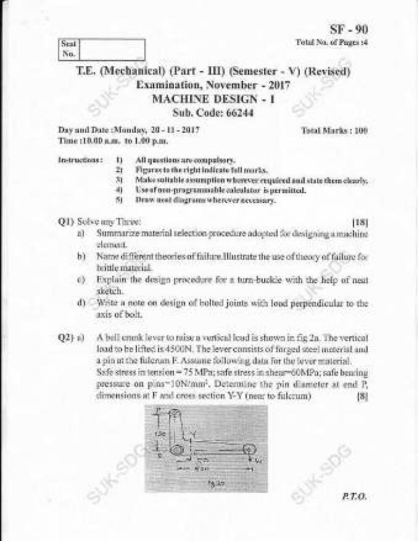
,
Seat
No.
Day and Date :Monday, 20 -ll -2017
Time :10.00 a.m. to 1.00 p.m.
T.E. (Mechanical) (Part - III) (Semester - V) (R )Examination, Novemb er - 2017
MACHINE DESIGN - ISub. Code: 66244
SF.90Total No. of Pages :4
Total Marks : 100
Instructions: All questions are compulsory.
Figures to the right indicate full marks.Make suitable assumption wherever required and state them clearll'.Use of non-programmable calculator is permitted.f)rarv neat diagrams wherever necessary,
Ql) Solve anyThree: I18la) Summarize material selection procedure adopted for designing a machine
element.
b) Name different theolies of failure.Illustrate the use of theory of failure forblinle material.
c) Explain the design procedure for a tum-buckle with the help of neat
sketch.
d) Write a note on design of bolted joints with load perpendicular to the
axis of bolt.
Q2) a) A bell crank lever to raise a vertical load is shown inflg2a. The verticalload to be lifted is 4500N. The lever consists of forged steel material and
a pin at the fulcrum F. Assume following data for the lever material.
Safe stress in tension: 75 MPa; safe stress in shear:60MPa; safe bearing
pressure on pins:l0N/mm2. Determine the pin diameter at end P,
dimensions at F and cross section Y-Y (neal to fulmum) t8t
1)
2)
3)
4)
s)
P.7:O.

SF.90b) Figure 2b shows a puliey bracket, which is supported by 4 bolts, two at
A and two at B. The weight of pulley and bracket, W is 1 850N,,4pd theload, F on the rope is 20kN.load, F on the rope is 20kN.
Determine the size of the h--- _-r-
Determine the size of the bolts, using an allowable shear stress of 40
MPa for the bolt material. t8t
ORc) A welded connection as shown in figure 2c is subjected to the eccentric
force of 7.5 kN. Determine the size of welds if the permissible shear
stress for the weld is 90N/mm2. Assume static conditions. t81
Q3) a) Discuss the design procedure for square key. t6lb) A splined connection with the following particulars is used for a gear anci
shaft assembly in a gear box. The power to be transmitted is 20kW at240 r.p.m. The bearing pressure on the splines is limited to 6.5.Mpaduring sliding. The coefficient of fi.iction is 0.1
Major diameter: 60mm
Minor diameter: 54 mm
Number of splines: l0Deterruine (i) The length of gearhub
ii) The force required to shift the gear.
-,'' oR
-2-
tl0l
Discuss the design procedure for square key.

SF.90c) Design a cast iron protective type flange coupling to transmit 15 kW at
900 r.p.m. from an electric motor to a compressor. The service factor
may be assumed as 1.35. The following permissible stresses may be
used:
Sh$a.r stress for shaft, bolt and key material:40MPa
... 'Clushing stress for bolt and key: 80 MPa' .,Shear stress for cast iron : 8 Mpa
Draw a neat sketch ofthe coupling. t10l
Q4) a) What are the various types of springs used in practice? Explain one
application ofeach. 16l
b) Design a close coiled helical compression spring for a service load ranging
from 2245N to 2745N. The axial deflection of the spring for this load
range is 6mm. Assume a spring index of 5. The permissible shear stress
intensify is 420 MPa and modulus of rigidify is 84kN/mm2. Assume
squared and ground ends for coil. Neglect the effect of stress
concentration. Draw fully dimensioned sketch of the spring.
Std. wire gauge (SWG) number and corresponding diameter of spring
wlre ts gl the followingtable.
Q5) a) Derive an expression for maximum efficiency for square threaded screw [6]
:'..,,' oR' What is recalculating ball screw? Explain with neat sketch.
b) The power transmission screw of a screw press is required to transmit
maximum load of 100 kN and rotates at 60 RPM. The trapezoidal threads
are to be used as under:
NominalDia.mm 40 50 60 70
Core Dia. mm 32.50 41.50 50.50 59.50
MeanDia.mm 36.50 46.00 55.50 65.00
Core Area mm2 830 1353 2003 2781
Pitchmm 7 8 9 l0The screw thread friction coefficient is 0.12. The tolque required forcollar friction andjournal bearing is about 10% ofthe torque to drive the
load considering screw friction. Determine screw dimensions and its
efficiency; Also determine the motor power required to drive the screw.
The maximum permissible compressive stress in the screw,is'100 MPa.
' [12]
l0l
-3-

Q6) a)
b)
SF.90Explain the step by step procedure for selection of V_ belt fromManufacturer's Catalogue.
t6]
It is required to select flat belt drive for a fan running at 360 rpm which isdriven by a l0kW 1440 rpm motor. The belt drive is open type andspace is available for a center distance of2 m approximately. ile beltshould operate at velocity between 17.g0 m/s ti )Z.SO m/s. The powertransmitting capacity of the belt per mm width per ply at 1g0" arc ofcontact and at a belt velocity of 5.0g m/s is 0.011g kW. The loadcorrection factor can be taken as 1.2. suggest preferred pulley diametersfor the motor and fan pulleys and give complete specifications of belting.Refer the tables given below.
t10l
Arc of Contact Factor (F
Standard Widths of these belts in mm
130 140 150 160 t7o 180 190 200
1.26 1.19 1.13 1.08 1.04 1.00 0.97 0.94
For flat pulleys: Series of preferred val,es of pitch .iiu*"t"^li, ,.*ffi ulfollows.
Pitch diameter (mm):
200 212 224
400 425 450
750 800 900
12s
.!.30
475
1000
L)Z
250
500
140
265
530
150
280
560
160
300
600
170
315
630
180 190
355 375
670 7t0
4..6A."6
-4-

SF.91Total No. of Pages : 3
T.E. (Mechanical ) (Part - III) (Semester - V) (Revised)
..i Examination, November -2017
. ..' MANUFACTURING ENGINEERING
', Sub. Code :66245 :
Day and Date : Wednesday, 22 - ll -20L7
Time: 9.30 a.m. to 1.30 p.m.
Instructions : f) All questions are compulsory.
2) Figures to the right indicate full marks.
3) Assume ifnecessary suitable data and state them clearly.
4) Use of non-programmable calculators is permissible.
SECTION.I
Ql) Solve any two:
a) Explain with'neat sketch the types of milling cutters. I8l
b) Derive.an expression for Shear strain. I8l
c) .. In an Orthogonal cutting of the material, Cutting force (F*,) :138Kg,
',Feed force (F,):68Kg, Rake angle (cr):7", Chip thickness ratio
(r):0.a. Determine
i) Coefficient of friction of chip
ii) Shear force (Fs) and normal to shear force (Fn). 181
Q2) Solve the following questions.
a) Define machinability. Explain the factors affecting machinability. How
the machinability index is defined? t81
OR
a) Explin concept of wear & types of wear with sketch. ,- -r.,,, t8l
b) Determine t8I
. . PT:O.
Total Marks : 100

SF.91i) Taylor,s Tool life equation
ii) !u]fi1s sneed for 6 minutes oftool rife when tool life of 70 minutesis obtained at a speed of 25mlmin and 15 minutes at 40nvm';..
Q3) Thg.component shown in fig. is to be processed on a single.spindle automat.Study the component and prepare:
.."'"irrt
a) Detailed process sheet
b) Tool Layout
c) Cam profile for drilling operation_of Q5 mm hole through
d) Calculate Production rate perhour
Material -g 20 Bronze bar All dimensions are in mm.
.6
SECTION - IIQ4) Design & draw neat dimensional drawing in three views with one sectionar
view ofjig for drilling two holes Q12 in the given bracket u, ,t o*., i, ngu...
126l:-. oRDesign & draw neat dimensional drawing in three views with one sectionalview of.l{illing fixture for creating plane s*rface
"f O 24;;I;;;;",bracket as shown in figure.
-2-
Fl{,l .-' ,
l..r:Irttr.Y
et
:8lT-t_
10
1-1{
I,

sF-91Also Justifr the selection of location, clamping & guiding elements.
, .d
Q5) Attempt any two.
a) Explain with neat sketch the Compound die.
b) Explain types ofStock stop.
c) Explain the importance of following in Press working
a) Construction & working of CNC.
b) Automatic Tool Changer.
c) CNC axes and drives.
d) Modular Tooling System.
aaa
-r \*,-'"_*\ag-,,
"!-;,
.-3'}'" Il2l
i. i']
16l
t6I
I6t
i,9
4.e!
-3-

(Semester - \) Examination,
i,. Sub. Code :66241
Day and Date : Thursday,0g - 1,1- 2017
Time: 10.00 a.m. to 01.00 p.m.
Instructions: l) All questions are compulsory.
2) Figures to the right Indicates full marks.
3) Assume any additional data if required and mention it clearly.
Ql) a) For the mechanical system shown in Fig. I a, prepare grounded chairrepresentation and construct electrical circuit using force current analog.
l6l
sF - 987Total No, of Pages : 4
November - 2017
'.''..'
Total Marks : 100
'l: .:"'- k5
Jz
kr
**r"
{ig ea
PT.O.

sF - 987b) For the fluid system shown in Fig. 1b, determine equation ofpl in terms
ofP2 and Pl6l
. .'.,.: Rf-- O- '--r
fi1 ru
c) For the thermometer shown in fig. lc, the ambient temperature is Ts ancltemleratulg,of fluid is T. The rate of heat flow from su,ounding mediumto the fl_r1i{.!C Q : C,(Ts - T) The rate of change of temperatu[ of fluidis D.T.!cr.Q construct the block diagram repiesentation for the svstemin.rvhich Ts is input and T is output. Determine time constant. 16l.,i-.
r{'r5
$g {c
Q2) a) Determine linear approximation for the equati on z - sinX. cos,,y forxi : 6.q: aiid yi : _ib., what is uppro*i,oo],. ,^u'tuJ"ri *J*"f : ur"an{ Y, *:28..
tgl
-2-

sF - 987
b) Reduce the block diagram shown in fig. 2b and obtain transfer firnction. [8]
cfs]
*3er
Q3) a) A hydraulic control system is shown in fig. 3a. The forcing function isr(t) : u(t) and all initial conditions are zero. Determine the response c(t)of system.
Y(&)
l8l
c rr.J
Si1- a a;
b) For the control systom shown in fig. 3b, determine K,, K, and a such
that the system will have a steady state gain of l, a natural frequency of2and damping ratio of 0.5. t81
Y({,) c{t)
fig.s b
(!+ l) (*+a)
-3-

sF - 987
Q4) a)
b)
to be stable.t6j
QS) a) Sketch the Bode plot for the transfer function
1000
S (1+0.1.S)(1+0.001.S) Determine gain margin and phase
ll0l
ooo
b) calculate break in point and angle of departure for the control system,given by characteristic equation Sr+ 25 + 3 + K (S + 2) = g. t6l
Q6) a) fhemoiion of a numericalry controlled machine toor is desqribed bv the
.' lifferential equation j + 7 .y + l}.y _ f (t) .Determine bomputer diagramand state space representation using parallel method. tgl
b) The motion of robot arm controlled by an electric motor is given by thedifferential equation j+6.y+9.y= f (t). Use series programming todetermine computer diagram.
lgl
G(S) =
margin.
-4-

2) Assume suitable data wh€rever required and mertion il clearl,!.,3) Figures ro lhe right indic{te full m ks.
Ql) a) Por the electrical network shor,r,n in fig. la, collstruct mechernical systc:11using force cwrent analog.
16l
t (" I
I - l-___r_{L--"rr"ryL*] I
Seal J
No,
Day.nd Date : Wednesday, l6-ll-2016Time : 2.30 p.m. to 5.J0 p.m.
Inslructions: 1) AII quostions arc compulsory.
-{, x-
1j
4h
T,E. (Mech.) (Semester - V) (Revisetl)Examination, November - 2016CONTROL ENGINEERING
Sub. Code : 662,1I
sJ-326TotEI No. oiPages: 4
Total Mrrl(s : 100
.TI
E
l-uGj.1a
hanical aad electdcai system shown in 1ig.l b areb) Show that the mec
analogous system.
+JI
KtIBLd
,)r.
Ag
.f
:< e-&V1r-1L__J_ T
EL
J"
P,T.O.

c)sJ-326
a mathematical model for two coupled tank as shonn in 1ig.1 c. [61
*90
9i
'fr'3 ' r c
Q2) a) For subsonic flow of air through a restriction, the mass flow rate is M =
b) Reduce the block dingram shom in Fig. 2 b and find tanstbr function. [8]
RG) cc5)
f-q. 2- b
Develop
{q
Hr(J)
q3 (s)
+'
s.]-326
Q3) a) For the unity feedback conlrcl system, shown il hg. 3a, calculate value
of kd so that sys:e.r is critically damped. Also calculate maximum
over;hoot and settlingtime. t8,
c(s)
{ig, a ab) A D.C. position controi system is show in fig.-3b. Detemine tle rcsponse
c(t) fol dt): s. u(t), d(t) = 0 and all initial conditions are zero t8l
Y(t) + 2_
D +6c cr)+
Fi3.:$
Q4) a) Using Rooths stability criterion, investigate the stabilily ola unity feedback
control system whose open loop transfer function is given by
K.e '
GlS)=-' -
.' S(S'+ss+e ) '
b) Sl(elch root locus for s)stem having
Kfs'-4.S+20)G(slH(s)=#(s+2.)(s+4)
t6t
u0l
scs r-2)
d (t)
-3-

s'I-326
Q5) a) Draw the bode plot for the unity feedback control system with
r o(s+10)C(S)= , :: ':: I-rom the plot determine
'alues olgain margin' s(s+2)(s+s) --"-
Q6) a)
and phase margin. lr2l
b) Obtain y(t) when x(t) is a unit step for the system shown in fig 5b [61
2{ cs)Y (s)
83sb
Determine state space representation and computer diagram by series
pro$arnming for the differential equation
(D: + 3D + 2) y(t): (D + 3).(.). t8I
For the differentiai equation (D + 9D'z + 24S + 20) y(t): (D+3) f(t),
determine stats space representation and coapulel diagram by generalb)
programmmg. 181
+++
-4-

Seat
No.
sJ-327Totsl No. of Pages : 4
T.E. (Mechanical Engineering) (part-I) (Semester_V)(Revised) Examination, November - 2016
THEORY OF MACHINES.IISub. Code: 66242
Day and Date: Snturdry, 19 -11-2016 TotalMarks : 100Time: 2.30 p.m. to 5.30 p.m,
Instrurlions: l) Alrqresfionsrremmpulsor-v.2) Figurestothe gh1 indicate tuI :narks.3) Draw reat labetted skeich whsr.evcr necessnN-4i Assume ifnece\san !uirabtc drta and rrate rirartr.5) Use olNon prograrnmable calculator is permitted.
Ql) a) Srare and derir e Lhe lau olcearint. lSl
OR
Differentiate between lnvolute and Cycloidal tooth profite and define thefollowingterms.
i) Pressure angle
ii) Circularpitqh.
b) Apair ofgears, having 40 and 30 teeth, respectively are of25" involuteform. The addendum lergth is 5 mm and module pitch is 2.5 flm. Ifthesmaller wheel is driver-and rotates at 1500 rynl. Find the velocity ofsliding at the point of engagemeflt and at the poilt ofdjsengagement.
u0l
Q2) a) Classilication ofcear hain.
OR
Explain the concept ofequivaleat mass and rnoment of inefiia appliedfor gear trains.
I'7,O.
t6t

Q3) a)
b)
sJ-327b) Fig. 2 b shows an epicyclic gear tmia. PinionAhas 15 ree.th arrd is rigidly
fixed inthemotor shaft. The wheel B has 20 teeth and gea.s with A, andalso with arurular lixed wheel D. Pinion C has I 5 teehh ard is integral withB (C, B being a compoutd gear wheel). Gear C meshes with aanularwheel E, which is keyed to the machiDe shaft. The arm rotates about thesame shaft on whichAis fixed and carries the compound wheel B, C. Ifthc n1olor runs at 1000 rpq find the speed of the machine shall. Findthg torque exeied on the machine shaft if motor develops a torque ofI00 Nm. t10l
Conclilion lor stability oftwo rvheel vehicle moving in a cLuved path.
t6l
An aeroplane makes a complete halfcircie of50 m radius, towards left,when flying at 200 km per hour. The rotary engine and the propeller ofthe plare has a mass of400 kg with a radius ofgfation of300 mm, Theeogine mns at 2400 rpm clockwise, when viewed from the rear. Find ttreg).rosoopic couple on the air craft and state its effect on it. What u,ill bethe elfect, ifthe aercplane tums to its right instead of to the left? [l0l
Q4) a) Derive the equation for coffection couple to be applied to make twomass system dynamically equivalent. 16l
OR
Derive an expression for velocity afldacceleration ofthe slidel of crankmechanism.
fir 2 b.

sJ-327b) A vertical engine running at 1200 rym with a stroke of I10 mm, has a
connecting rcd 250 mm between centres and centre of the connectinsrod is mass 1,25 kg. The mass centre ofthe connectilg rod is ?5 mrifrom the big end centre and when suspended jiom the gudgeon pin axismakes 2l oscillations in 20 seconds IlOI
i) Calculate the radius ofgyEtion ofthe connecting rod about an axislhrough its mass centre. -
ii) When the crank is at 40" from the top dead centre andthe piston ismoving down\,vards, find analytically, the acceleration of the pistoL.r
and the aflgular acoeleration ofthe contecting rod. Hence find theinedia torque exerted on the crank shaft. To make the two mass
system to be dynamically equivalent to the connecting rod, necessary
correction torqrE has to be applied and since the engine js vertical.
$avity eflbct are to be considered.
QS) a) Explain what is multi cylinder inline engine, Also explain conditions tohave primary ar,d secondary lbrces and couple baiancing in multi cylinderinlineengine. l6l
OR
Explair the balancing ofseveral masses rotatilg in same plane.
b) The crank and the colrnecting rod ofa 4-cylinder in-line engine runningat 1800r.p.m, are 60mm and 240 nrm eachrcspectively andthecylinde$are spaced 150 rDm apart. Ifthe cylinders are numbered 1 10 4 in sequence
&om one end, the cranks appear at intervals of90o il an end view in the
order 1-4-2-3. 'lhe rcciprooating rnass corresponding to each cylinder is
1.5l(g. Detemine: It2l
i) Unbalanced primary and secondary forces, ifany, and
ii) Unbalanced primary and secondary couples with rgference to centmlplane ofthe eagine.
-3-

Seat
No.
s.I-328Total No. of Pages : 3
Tota: Marks : 100
T.E. (Mech.) (Part - II! (Semester _ V)Examination, November _ 2016
HEAT AND MASS TRANSFERSub. Code : 662C3
Day and Dat€ : Tuesd ^y,22-U'2016Time: 2.30 p.ln. to 5.30 p,m.
IDslrricfions: 1) Allquestionsa.rcompulsory.
2) Figureto the right indicates fullmnrks.3) Assumesuiaable data whenevcr Nccessa$ nnd Stale il cle:rrt].4) Lrse ofspecifrc calculatols is permitterl.
Ql ) Solve an) three:
a) Define crilical .ailius ofinsulation. Also dsrive the equatiol for criticalradius ofinsuiation j.or hollou, cyiirder.
t6i
b) Explain the different modes of mass tronsler. Explain with suitableexamples. 16l
c) A 0.8 m higtl and 1.5 n wicle double pane windorv consist oftwo 4 ml]1thick layer of glass (k:7g WmK) separated b_r t0mmwideslgnanrair space (k - 0.0626 WmK). Detcrm ine th" .ut. oth.ut t unri-". tf,.tuglthis window u,.hen room is maintaired at 20,C artd out"li" u;. i, ut,10"C. Take cumulative heat tmnsfer coefficient as i 0 and40 Wnt'K. [6]
d) An aluminum pipe caries a steam at t 10,,C. T5e pipe (k : i g5 WrnK)has I inner di,rneteroI l0 cm and oLrler di.rrn"r"r'ot r: crr. l he pi;. r.located in a r.oom i.vhere the ambient cir remperature is:0,'C anAconvective heat transfer coefficient is l5 WmrK. Determine heat transl.errate per. unit leng& of pipe. Neglect coflvective heat transl]er on sleamside.
16l
P.T.O.

sJ-328Q2) Solve any two:
c)
")Derive expression for temperature distribution of a solid cylindergenerating heal a1 the .atc of 4 unit per unit volume. tgl
Explain Lumpedheat capacity analysis. Also give the physical significanceof Fourier's number
ISI
A "olid topper sphere ol l0 cm diamerer qr 8o5a Lg m', C- - lgj J.
kgK- k . ld6 \L rrh r. Inirially at rnilorm temperarule 250"( .,r':urloenlrinrmer'ed irr l fluid whieh is mainr"ined ar unilorm tcmperaru_re of50oC.Tie heat tra.sl-er coelficient between sphere aucl fluicl is 200 WmrK.Determine the lemperatu.e ofcopper sphere at 5 minutes afterimme$ion,
t8l
Q3) Soh,e any:rvo:
b)
Wm'zK. What will be themtal corductivihr of the rorl? I8I
b)
c)
Derive an expression for temperatue distribution along &e length ofapin Iin having insulaled rip. I8l
A J tn long, 5 cn diameter cylinder placed in an atmosphere of 40.C isprovided wiah l2 fins (k: 75 Wmk)" 0.75 ,rm thick. The fins orotudes1.5 cnr tiom the cS linder sur.ac<. The heal transler coefficicnt is lj.JWm'?K. Calculate the rate of heat transf'er if the surlace temperature ofcylinder is at t50oC.
I8l
Determine thernal conductlvity oflong solid 2 cm diameter rod. one endola rod is insenttl irl a ftrndce whilc remaining ponion is projected oulin air at 300C. After steady state has been reachecl, the temoeratrure att\ o point( on th( iod \-\ hich are lOcm afart ar.c ncasurcd and found robe 1200C aad 900C respectively. lf coefficient of lreal transfer is 20
Q4) Solve anv threc ofthc follorving:
a) Analyze tl.reproblem olforced convection by using dimensional analysistechnique.
t5l
b) Wdre a shoft note on thermai boundary layer I51

A verlical cylinder 2m high and 20 cm in diameter is mairltained at atempeEture of 100'C in an atmospherc of20"C. Calculate the heat Iostbyfi.ee corvectjon liom :his cylinder The propelties of air at 60"C are,p : 1.06 kg/mr, Cp - I 008 J/kg K, k : 0.028 W/llrK, p : 20 x I0jN sec/
m', v = 18.97 x i0+ m2/sec. Use the co:relation Nu = 0.12 (Grpr)r/r. [61
0.5 kg/minute ofwate! is heated from 20"C to 40"C by passjrg through asteel pipe of 2.5 cm diameter which is maintained ai 110,,C. find thelength ofthe pipe required, The prope:ties ofwater are p:978 kg/rni,Cp:4200 J/kg K, k = 0.575 WmK, v:0.415 x 10+ nf/sec. Use rhecoreiation Nu = 0.023 Reo 3. Prorr for turbulent flow and Nu = 3.65 ifthe florv is lan'iinar.
Q5) Solve Any three ofthe fbllowing:
I6t
State and explain Planks lalri
What are the valiolls theories ofradiation heat bansfer?
The tempelature of a llame in the lurnace is 1900K. Find Monocfuomaticemissive power at the maximum wavelength. t6i
d) Determine the heat lost per meter length qf8 cm diameter tube at 300"Clocated in a large room with rcd bdck walls aa a temperatue of 27"C.Assume enissivity ofpipe as 0.79.
t61
Q6) SolveAuy three ofthe follou,ing:
a) De.ive the expression for Ellectiveness for parallel fiow heat exchangerl6l
b) Define the follou,ing telms in connection withheat exchanger t6]
J) LMTD
ii) NTU
iii) Effectiveness
iv) Correction fartol.
c) Write a short note oo design considerations ofheat exchaflger. 151
b) Write a shorl note on NusseJt's theory of film $,ise condensation. ISI
+++
c)sJ-328
Isl
t6l
d)
a)
b)
c)
-3-

/
s.I-329Total No. olPages : 4
T.E. (Mechanical) (Part - III) (Semester - V) (pre-Revised)Examinafion, November - 2016
MACHINEDESIGN-I
Sub. Code : 66244
Day and Date : Thursrtay, 24 - 11 - 2016 Total Marks I 100Time : 2.30 p.m. to 5.30 p.m.
Instructions: l) All qu$tions arccompulsory.
2) Figures to the righl indicate full Barks.3) Make suitable assumptions wherever requireal and st:rae them crearlv.4) Usc ofnon-programmalrle cal.nlator is pcrmitted.5) Draw next diagrams $,herever nec€ssary.
Seat
Ql) Solve any Three:
a) State and explain the various steps involved itlelement.
tr sl
design ol a machine
b) Suggest with justification the suitable material for the following:
i) LeafSpring in automobile
ii) Lathe bed
iii) Helrret (Two wheeler)
c) Explain the design procedure for a knuckle joint wlth the help of neatsketch.
d) What is a butt weld joint? Discuss design ofbutt weld.joint urder tension.
Q2) a) A tum-buckle used for a stay rope of an electdc post subjected to aforce of 15 kN. The permissible tensile stress tbr the steel rods usecl is70 MPa. The permissible tensile and shear stress for the cast iron nut
t8l
P.',|:O.
used is 30 MPa. Design the turn-buckle.

sJ-329b) A cast iron bracket fixed to the steel suuctwe is shown in figure 2a. Ir
supports load P of 25 kN. Ttrere are two bolts at A and two bolts ar B.The distances are as foilows: l, : 50 mrl l, : 200mm I : 400mn.r.Determine the size of bolts, if maximum permiisible tensile stress in thebolts is 50 N/mh,
;
t81
c--
8,.
{q z.
Designation Pitch (mm) Major or Nominaldiameter (mm)
Minor or Core
diameter (mm)
Mi0 3.s0 30 25.706
M36 4.00 36 31.093
M42 4.50 42 36.479
M48 5.00 48 41 .866
OR
b) Figure 2b shows a plate brackel welded to a steel column. anrj loadedeccentr'.call1. Assuming that Lhe size of r-reld is omrn . bmnt, detenninethe maximum stress induced in the weld.
?=
P:15000N
E
ef F l
tI
3ta
-2-

Q3) a)
b)
Discuss ASME code for shaft design.
sJ-329t6l
Design a shaft to transmit power from a[ e]ectric rnotor to a lathe headstock through a pulley by means of a horizontal belt drive. The pulleyweighs 20 kg and is located at 100 mm from the center ofnearest bearing.Diameter of the pulley is 200 mm. Ma-ximum power transmitted is L 1
kW at 120 r.p.n. Angle of lap of belt is 180" and the coefficient olfi iction between the belt and pulley is 0.3. Shock factors in bending andtorsion are 1 .5 and 2.0 respectively. Allou,able shear stress in the shafL is35 N/mm'z. The puiley is mounted overhung on the shaft.
OR
[10]
It is required to design a rigid type of flange coupling to connect rwoshafts. The input shal1 hansmits 37.5 kW power at 1g0 r.p.m. to theoutput shaft th.ough the coupling. The design torque js 1.5 tirrles therated torque. The matedal fo. shaft is 40C8 (S,_ = 3g0 N/hm,, lbctor ofsafeq/: 2.5), material for key:30CE (Sy, :40-0 N/mm:, i'actor ofsaiery:2.5), material lor flange FG 200 (S,,:200 N/mnf, factor ofsafety:6based on ultimate sbength).
Derive an expression for dcflection ofhelical spring ofcircular wire. [51
Design aclose coiled helical compression spring fora service load ranging&om 2245N to 2745N. The axial deflectior of the spring for this loadrange is 6 mm. Assume a spring index of5. The pemrissible shear sfessintensiry is 420MPa andmodulus ofiigidiry is 84kN/mn.r,. Assume squaredand gound ends for coil. Neglect the effect of stress concentration.Draw fuily dimensioned sketch ofthe spring. l11l
b)
Q4) a)
b)
Qs) a) Derive an expression for torque required to raise the load using squarethreaded screw.
16l
OR
Discuss Valious foms of threads used for power transmissior.r givingtheir relative merits and limitations.
Std. wire gauge (SWG) number and conesponding clirur.reter of springwire is given in the following table.
1i.785 10.160
-3-

Seat
No.
sJ-330Total No. of Pages : 3
Examination, November . 2016MAIIUFACTURING ENGINEERING
Sub. Code :66245
Day and Date : Satur d,^y, 26 - ll - 2016
Time:2.30 p.m, to 6.30 p.m.
lnstructions: l) Allquestionsarecompulsory.
SECTION-I
Q7) Solve any two.
a) Derive an expression for Shear strain. State clearlymade.
Explair with neat sketch the types ofreamer.
(In) ii) Coefficient offriction ofchip.
Q2) Solve the following questions.
a) Explain concept ofwear & types ofwear with sketch.
T.E,(Mechanical Engg.) (Semester - \) (Revisetl)
Total Marks : 100
2) Figures to the rightindicate full marks.3) Assume ifnecessary suitable alala anal state them clearly.4) Usc ofnon-programmablo calculators is peranissiallc.
the assumptions
t8l
t8l
t81
In an fthogonal cuttirg ofthe mater.ial, Cutting force (F,,):150kg, Feedforce (F,) :80kg, Rake angle (o ):8., Chip thi&nessralio(r,-0.J.Delennine it Shear lorce 1Fs1 and l'omal ro ,hear. Iorce
b)
c)
[81
OR
a) Define machinability. Explain the factors affecting machinability. Howthe machinability indexis defined? t8l
P.7:O.

b) A Tool life of 60 minutes is obtained at aminutes at 40nr,/min.Determine
i) Taylor,s Tool life equation
ii) Cuning speed lor g minutes of tool lile.
s.I-330speed of 20mlmin and i 6
t81
Q3) The comFonenl shown in fig. is to be processed on a single spindleautomat.Study the component ard prepare:
tfgla) Detar'led process sheet b)Tool Layout
c) Cam profile for drilling operation d)Calculate production rate per hour
Material -Q 20 Bronze bar. All dimensions are in mm
SECTION-II
Q4) E Design & drawneat dimensional drawing in three views witi one sectionalview ofjig for drilling two holes Q 12 in the .,bottom
p1",",, "i,fr"
gir",bracket as shown in figure. p6l
OR
-2-

sJ-330Desigt & draw neat dimensional drawing in three views with one sectionalview of milling fixture for creating slot of3mm ofthe given bracket asshown in figure.
Also justifl, the selection oflocation, clamping & guiding elements.
@5) Solve any two.
a) Explain the importance offoLlowing in press working
D Strippers
ii) Ciearance
b) Explain with neat sketch the progressive die.
c) Explain tlpes ofstock stop,
26) Write sho.t notes on any three
a) D;amond Locator.
b) Automatic Tooi changer
c) Modulartoolingsystem.
d) Strip layout.
I6I
t6l
t6l
112l
tt.:.
-3-

sL-313Total No. ofPages : 5
_J.E. (Mechanical) (Semester-\.)
. ':r' Examination, May - 2017
CONTROLENGINEERING .}.' Sub. Code: 6624t
Day and Date : Monday, 15-05-2017Time: 10.00 a.m. to 1.00 p.m.
Total Marks : 100
Insfructiotrs i 1) All questions arecompulsory.2) Assume any additional data ifrcquired anrl mention it clearly.3) Figures to the right indicate f]lll marLs.
Ql) a) For the mechanieal system s}rown in fig.la, construct grounded chairrepresentation and electrical networkusing tbrce current analog. t61
{a I a.'J '
b) A block ofmaterial at temperature T is placed in an oven which is 1.reld atthc constant temperature T,. The rate olheat flow q into tlre material isgiven by q = hA(T, - T), where h is the coefhcient ofheattransfer ofthesurface, A is the area of the surface and T is the temperature of the
block. The rate of change of remperarure of the block i, {=-!-' r/r MC,where M is the mass and C is the average specific heat. Determine thedr tterenttal ,eqlration which describes the temperature ofthe b16ck as aflmction oftinre. Identif,/ the time constant. .t- t61
.a' ,,.
. PT.O.

sL-313c) Forthe fluid system shou.n in fig.1c, determine the equation forpressure
P (head H: P/p) as a function ofinlet pressure Pr. t6l
CF!
fig lc
Q2) a)
iEp'pby, M = L05A
^/I# . The area ofrestriction A and the temperatue,' \/ T
T are constants. Detemine the linear approximation for mass flow rate
due to change in pressure drop (p, - pr) and due to a change p, in the
downstream pressure. t8l
b) The speed torque curyes for a dc motor are shown in fig. 2.lb, where V
is the appliedvoltage, N isthe speed and T is the output torque. Determine
the linear approximation for the change in torque t due to a change iu
speed n and a change in voltage v, The motor drives an inertial load such
duthat r=,I -, where J is the mass moment ofinefiia. For J = 0. 1, detQ4nine
dt1
the differJntial equation relating the change in speed n to the cliange in
vo.!!a!&. Determine the time constant x and the steady state gain. [8]
'.-, a i
- f 2-

sL-313N
i.
{9P'
loo
$io .1. a b
/^a i; I :,,
.,. 1 0R . "r',..,
' b) Redu€efhe block diagram shown in fig 2.2b and find transfendlnction.[8]
go
{h r,z b
c(s)
,:
-3-

sL-313QJ) a)
Io11|r; .f.1.-
11r"*" in fig. 3a, find K and K, so that maximum overshoot
is l0% arrd selrling time is 0.05 sec.,. [8]
c cs)
ris ' ' o
b) For the integral control system shown in fig. 3b, determine the value ofK and a, such that the characteristics equution f.,r, ur"ui .o"iui_ f
"rA "real root at - 5. For this value of I( and a, determine the resfonse c (t)$,hen r (t) = 0, c (0) = 4 and c(0)= 0.
t81
RC s)
Y(L) +
R(s)
,.' {ig. +c
cct)
is shown in fig.4a.
112')
.,
{ig. rb
Block diagram for helicopter stabilizing systemConshxct root locus plot for this system.
.a ,
Q4) a)
S Csz+ lr'S + +s)
-4-

sL-313b) For the system shown in fig.4b, detemine the range ofvalues ofK such
that the svstem is stable.
fig. +u
Q5) a) Explain the following terms.
i) Lead compensator
ii) Lag compensator
iii) Lag - Lead compensator
Q6)
,- [61
t8l
t6l
b)
a)
10Sketch Bode plot for c(S)= S(S;lXS+, with uniry feedback., [10]
The niotidn ofa driverless vehicle is described bythe differen-ti4lvequation
2tD + 5\!(1) = ' -' f(r)' (D+2)lD+3)"
Detennine the computer diagram and state space r.epresentation by
i) Series programming
ii) General programming t8lFor a unity leedback system with an open loop transfer function
Ktit\l=_ - ,,"'' '- S(S"rr, (S.,.4) lind break awaypoint and intersection ofroot locus
with imaginary axis.
^+++
b)
...,
KCs+{6)
sCs2+ t+s + j-s)
-5-

T.E. (Mechaitical Engineering) (Part - I) (Semester - V)
. THEORYOFMACHINES-II
Sub. Code: 66242
Day and Date : Tuesday, l6-05-2017 TotalMarks:100Time: 10.00 a.m. to 1.00 p.m.
Ins*rctions i 1) All questions arc compulsory.
2) Figures to the right indic.te lull urarl(s.3) Drax ne:rt labelcd sketch wherover tecessan.4) Assumt ifnecessnq, suitable d.ta and statc it elearly.5) Use ofNon programmable crlc lator is pcr.initted.
QI) a) State velocity of sliding and prove tlrat the velocity olslJdirg is
. proporlionnl to the distancc ofthe point of cortact fiom the pitch point.lgl
OR
Derive an expression 1br minimum number olteeth required on pinion toavoid interference in mesh tvilh gear.
b) A 20" involute pirion with 20 teeth iirives a 50 reeti gear. Module is8 mm. The contact ratio is to be maximum without interference. Find thetrvo addenda, length of arc of contact and contact ratio. It 0l
Q2) a) How the velocity ratio of epicyclic gear train is obtained bv tabularmerhod.
16l
OR
sL-314Tolal No. ofPages : ,1Sent
No.
(Revised) Examination, l/Iay - 2017
Write a note on Ineftia geared system.
P.T.O.

b)sL-314
An epicyclic gear train for an electric motor, is showll in Fig. 2b. Thervheel S has 15 teeth and is fixed to moror shaft rotating at I 450 rym.The planqt. P has 45 teeth, gears with fixed ar.mular A and rotates on aspindle carried by an ann which is fixed to output shaft. The planet palso gears witl the sun rvheel S. Find the speed ofoutput shait. If motoris transmitting 2 lIP, find the torque required to fix the anlular. t10l
Fi!.2 b
Q3) a) Draw Gyroscopic couple figure and de hne the followirg tems; t6]
i) Ax is of Spin
ii) Plecessionalangularmotiolr
iii) Axis ofPrecession
The turbine rotor of ship has a mass of 900 kg and radius of gyratiolr
600 nrm. It rotates at 1800 rpm clockwise when looking lrorr the sterfl.
Determine the gyroscopic couple when: [101
i) Tle ship is travelling at:10 km,ihl and steers to the left in a curve of100 m radius and its efiict;
ii) The ship pitching and the bow is descend rg with maxi:lrum velocily.The pitchilg is simple harmonic, the periodic time being 3 0 seconds
and the total angular moment bet$,een re extreme positions is 12o.
b)
-2-

Q4) a)
Qs) a)
Derive an expression for angular velocity andcolxlectillg t.od.
sL-314angulal acceieration of the
I6l
OR
Derive the equation for coffection couple to be applie<l to r.rake t\^,.omass system dyramical ly equir.alent.
b) The connecting rod ofa gasorine engine is 300 mn betw.een its centr.es.It has a mass of I5 kg and mass moment olinertia o1.7000 kg _ mm2. Itscentre ofgravity is at 200 mm fiom its small end centre. Det"ermine thedynamical equivalent two-mass system ofthe connecting rod iiore otthe masses is located at the smail end centre. ll0i
Explain_primary and secondary unbalanced forces of reciprocatingmasses. Write the maximum values of lhese fbrces and the position ofthe crank at which these maximum values occur 16l
OR
Explain partial balancir.rg ofunbalanced pr.imary force in a recipr.ocatirgengiire.
b) A shaft carries four n.rasses in parallel planes A, B, C and D in this orderalong its Length. The masses at B arrd C are I g l<g and 12.5 kg r.espectively.and each has an eccentricity of 60 mm. I-he ,ri".se, ar a a]rd O t r"" r.,ecc€ntticity ol80 tnm. The angle between the masses at B and C is I 00"and that between the masses at B and A is I 90., both being measured inthe same sense. The axial distance between the planes a-and e ls I OOmm and that between B and C is 200 mm. If the shaft is in compietedynamic balance, detennine: f|li) The magnirude of the masses at A and D;
ii) The distance between planes A and D: and
iii) The angular position ofthe n.rass at D.

Q6) a)
b)
sL-314Derive the expression for tensile or hoop stess due to centrifugal forcein fly.wheel rim. 16I
A multi-cylinder engine is to run at a speed o1600 rpm. Or drawing thetumin! moment diagram to a scale of 1 mm : 250 Nm and-l ,mm = 3o-
the areas above and belorv the mean torque line in mm,.q1,ia:,
+160, -172, +168, -191, +197, -162. The speed is io be kept within
! 102 of the mean speed of the engir.re. Calculate the necessary moment
of inertia of the fl).wheel. Determine the suitable dimensions ofarectangular flywheel rim ifihe breadth is twice its thickness. The densityof the cast iron is 7250 kg/mr and its hoop slress is 6 MPa, Assume t1rat
the rim contributes 92% ofthe fl1-wheel effo*s. I101
e
-4-

sL-31s'Iotai No. of Pages : 4Se.t
No.
T.E. (Mechanical) (Part-III) (Semester-\.)(Revised) Examination, l'4ay - 2017
HEAT AND MASS TRANSFERSub. Code : 66243
Day and Date : Wednesday, 17-05-2017 Total Marks : 100Time: 10.00 a.m. to 1.00 p.m.
Instructions : l) All Questions {re compulsory.2) Figures to thc rigLt iirdiratc full marks.3) Assumc suitable Dnta whcrever. neccssary and state it elearly.4) flse ofscientilic nou programmable calculator is permitted,
Q1) Sol,,,e any three.
a) Explain the dilferert modes ofheat transler u,ith suitablealso give basic law for each one.
b) Define overall heat transler coefficient, and also derive an expression loroverall heat transfer coefficient ,LI,, for a composite wall hai rng Lwo
' plates in series with therrnal conductivities ,K. ,and .K,,', having hot 1,luid
at temperature 'T,, rvith heat transfer coefficient ,h; on one side andcold fluid temperature ,T ,with
heat transfer coeffitient ,h ,on other
sroe. 16l
c) The wall ofaa oven is 40 cm thick having its thermal conductivity of0.7Wmk. The interior surface of the oven is maintained at a temperaturc of800'C and the ouBide wall remperature is 200"C. The toLal surlace areaof r.vall ofahe oven is 2mr. Find the thermal resistalce, heat fl olv raie andthe l,eat flux.
t6ld) A plane wall is 15 cm thick ofsurface area 4.5m2. Thennal conductivitv
ofthe uall is 9.5Wmk. The imer aud outer surface ofthe wall is maintarnetlat 150'C ar,ld ,l5"U respectively. Determine,
i) Hear llow rate acruss the $all
ii) Temperature gradient in djrection ofheat flow.
example and
t61
I6l
P.T.O.

sL-315Q2) Solve the follou,ing.
a) Derive the general heat conduction equation in Cartesian co-otdinatesystem. Also wdte the special cases ofthis equation. t81
OR
b) Derive the equation for temperature distribution and heat transfer.for a
solid sphere under stead,v state condition with unifom heat gencration
and convert it in terms of outside heat transfer coefficient and outside
temperature ofthe fluid 'T- '. I8]
c) The steadv state temperature distribution ir.r a plane wall is given as,
T = 600+2500x 12000x,, whele 'T' is in 'rC' and 'x' is in metermeasured from the surface oloutel wall. One dimensional steady siate
heat conduction occurs in the wal1. Assuming the thermal conductir itl(k,.,r:2.35 Wmk) and thickness has 0.3 m. Dclermine,
i) The surl'ace temp. & ave:'age temp. of the wall.
ii) The maximum remperature ir the wall & its location.
iii) The lTeat flLlxes at the surf'aces.
Q3) Solve any two.
a) Write shofi notes on,
I8l
i) Types and classification offins,
ii) Fin efficier.rcy and fin effectivcness.
I81
b) What do you meaa by initial and boundary conditions'? What are the
lypes of boundary conditions'? I81
c) Fins are provided to increase lhe rate olheat h.ansfer lron a hot surlace.
Which ofthe lollowing rvill t have maximum heattransferrate:
i) 6 fins of 10 cm length.
t8l
ii) 10 firs of6 cm length.
(Take 'k'for fin :300 W/mh, h:20 Wm,k, cross section area offin : 2 cm2, perimeter : 4 cm, Temperature ol hot surlace : 230"C,
Temperature of sorrounding air : 30"C)
-2-

sL-3tsQ,l) Solve any two of the following.
a) Explain the phenomenon ofNatural Convection and l.orced convection.What isu.rean film temperature alld Bulk mean temperature? 181
b) Waler at the rate of0.8 kg/s at 90"C flows through a sreel tube l.raving 25 rnmID and 30 rnr OD. The outside surface temperatue ofthe pipe is g4"C andtemperatLte olsui-ronding air is 20"C. The room pressur.e is 1 atm and pipeis J5 rn long. How much heat is lost by free convectiolr in room. Usecorrelation Nu: 0.53 (GrPr)o r5. lake propefiies ofajr as p : I .0g77 kg/11r,
v: 1.9606 x l0 i kg/m.s, Pr: 0.702, k, - 0.02813 WmK. t8l
c) Air at 20"Ci and 1.013 bar i'lolvs over a flal plate 40 m/s. The plate is I mlong and is maintained at 60"C. Assuming unit depth, calculate the heattrar.rsfer from the plate. Use tl.re correlationrNq : (pr),rrr[0.037(Re,
)0 sg50J
Properlies olair at 40'C are, p : 1.128 kg/m', C.: 1.005 l(j/kg"C,k : 0.0275 Wm"C. y: 16.qb. 10 "mrrs, pr : 0.699. t8l
Q5) Solve rny lwo olrhe lollowing.
a) State and Explain;
D KirchotT's Larv
l) Wien's Displacement Law
iii) Lambert's Cosine Law
ir.) Planck's Law
b) State Planck's law and Stefan Boltzmarn law and hence derive StefanBoltz:nann lau, fiom Planks larv. lg]
c) Calculate the following for an industrial furnace jn the {brm ol blackbody and emittirg radiations at 2500.C t8l
i) Monocluomatic emissive pou,er at rvavelength l .2 v m
ii) Wave Iergtlr at which emission is marimum
iii) Maximum emissive power
ir) Total emissive porver
181
-3-

Q6) a) Write shofi notes o:1 (any two);
sL-315lt2l
i) Types ir.f fouting and its causes
ii) lgol Boiling Cuwe
iii) Explain classifi cation of heat exchanger with neat6l&tch.
b) :iMater at 225 kglh is to be heated from 35'C to 95"C by means ol'
concentdc ttrbe heat exchanger. Oil a t 225 kglh and 210"C with specif,c
heat of2095 Jlkg.K is to be used as hot fluid. lfthe overall heat transfer
coelficient based on ouoter diameter of the imer tube is 550 Wm'?K
Determine :he length of heat excha.ger, if the outer diameter is 100 mm.
t61
.)'
+++
-4-

sL-316Total No. olPages : 7
D
ii)
in)
c)
d)
chanical) (Part-III) (Semester-\7).
(Revised) Examination, May - 2017
MACHINE DESIGN-I' Sub. Code:66244
Day and Date i Thursday, 18-05-2017
Time : 10,00 a,m. to 1.00 p,m.
Instructiotrs: 1) All queslions arc lompulsora.
Total Mark : 100
2) Figurcs to the right indicate full marks.
3) Make suitable assumptions rherevel required rnd state fhem elesrl).4) tlse of non programmable calculator is permitted.
, Draw neat diagrams $herever necessary.
Ql) Solve a ythree. t18l
a) Describe various steps involved in design ofa machine element.
b) Suggest rvithjustification the suitable material for the following;
Side Stand Spring olBike
Lathe Tail-Stock
Water Bottle
Draw neat sketch ofa knucklejoint and explain the design procedure,
Explain design ofbutt weldjoinl under tension.
Q2) a) A tum-buckle used for a sray rope ofan electric post is subjected to a
force of 15 kN. The permissible tensile skess for the steel rods used is
72 MPa. The pemissible tensile and shear stress forthe cast iron co[p1er
nut usedis 32 MPa. Design and sketch the tum-buckle. I81
P.T.O.

'-Y\
sL-316b) A cast iron bracket is fixed to the steej structure as shown in figure 2b. It
supports a load P of 30kN. There are two bolts at A and two bolts at B.The disrance are as follows: i = 50mm, /, = 300mm and / = 600nm.Detenrine ihe size oIthe holts. ir'ma\imum perrnissible lensite srrcss inihe bolt is 50N/mm?.
Designation Pitch (mm) Major or Nominal
diameter(mm)
Minor or Core
diameter(rnm)M30 3.50 30 25.706M36 4.00 36 I i.091M42 4.5 0 42 36.479M48 I 500 48 41.866
I81
D
F,6 rl
ORc) A plate bracket welded to a steel column, and loaded eccentrically is
shown in ligure 2c. Assumirgthat the weld ifthe size ofweld is 6xiim,determine rhe maximurn stress induced in the weld. Civen: b = 1iOmm,F = 15kN, r t8l
!l*l
trh -.
-2-

sL,316Q3) a) Demonstrate the use ofASME ccde for shaft design with suitable example. [6]
b) Design a shatl to transmit pou,ei fiom an electric molor to a lathe head
stoci( through a pulley bv means of a horizontal belt drive. The puilevweighs 200N and is located at 100 rnm from the center olnearesi bearing.
Diameter of the pulley is 200mm. Maxirnum power transmirted is L2kWat 120r.p.m. Angle of 1ap of belt is 180. and the coeflicient of frictionbetweeo the beh and pulley is 0.3. Assune shcck lactdrs in bending and
torsion as 1.5 and 2.0 respectively. Allorvable shear stress in tl.te shafl is35 N,tmm'?. The pulley is mounted overhung on the shait. I10l
OR
c) Design a rigid type of flange coupling to conncct two shaits. The inpurshaft tmnsmits 37.5 kW power at 180 r.p.m. to the output shaft throughthe coupling. The design torque is i.5 times tlle rated torque. The matelialfor shall is 40C8 (S., = 380N/rnmr. factor ofsafety - 2.5), mareriai forkey = 30C8(S,, = 400N/mmz, factor ofsafety = 2..5). iriater.ial lor flangeFG 200 (S,r: 200N/mm1, factor of safety = 6.00 based on ultimate
Q4) a)
b)
srrength). ll0l
Explain ivith neat sketches stvles ofeDds ofhelical conpressiou springsindicating active number ofturns in each case.
{61
Safety valve of 60 mm diameter is to blow off at a pressure of1.2 N1mm'?. It is held on irs seai by closed coil helical spring. Themaxinum lift of vah,e is 10 mm. Design a suitable compression spdng ofspdng index 5 and providing an initial compression of 35 mm. Themaximum shear stress in tlie material of wire is li11rited to 500 Nlim:.The modulus ofrigidity for spring material is 80 kNr,nrnz. Assume squared
aud ground ends. Calculare:
i) Diameter of spring wire
ii) Mean coil diameter
iii) Number of active tums and
i\, Pirch ofthe coil
r..l 0.615Assume \Mral s Stress facror K = '' - + -: :-tc_-t c
l10l
Standard wire gauge (SWG) number and corresponding diameter ofspling wire isgiven in the following rabie,
SWG 4,/0 5i0 6i0 '710
Diametei
(ftn) 10.160 10,973 11 .785 12.70

Q5) a) Derive an expression for SL-3I6threaded screw
torque rcquired to raise the ioad using square
161.oRa) Wlar do 1 ou urrdersrand b.
Fc."*Jd; ;;:ffiT#;;:ifii;;:l#:l1T1.* * o"wer sc,ew?
b) 1te nominat diameter oftriore 1,.",;": """"::- "" 16l
pitch is 8 mm. Ir is u."o *ilJ','::?1'l^::rew threatl is 50 mm, while the
*a i*". aiu-"t., ul #[l"l,to"-^t'ut'ing outer diarteter of 100 mrr
as well as collar surfa"" rl ,'nt:ottrtltnt offriction at tluead surface
"r""a"rrstrrLu.irg'"'a1'betakeuas015 The screu is used to raise
r) rorque requireo ," .",:;:,;"i:"ory ror coltar friction, carcurate
ii) Torque requircd to lower rhe load, Il0l
iii) The force required to raise the load ifappiied at a radius of500 mmQ6) a) Erplain rhe step by srco r
,u*rr""*.".:" d"rjrffi pro".dr.. lor selection of Flat belt lrom
t6lb) It.is requjre to,Jesign a V_bclL drire ro connccl a 20 kW. 1440Motor ro a cump.s"!g1 r.urruno ,r ,1tn "^* r^.- ,. , rpnl.
space is available for a cenl - '"" 'r,'lr, rvr lJ ltotrrs Der dav. The
rnrto*-;ng oriu, -'- -' - LUrrier drstarce of approximarely j 2 ,,.'R"f",
II 2II)etermine:
r) Diameters ofmotor and compressor pulleyii) Belt specifications
iii) Corect cenbr disrance
iv) Number of belts
-4-
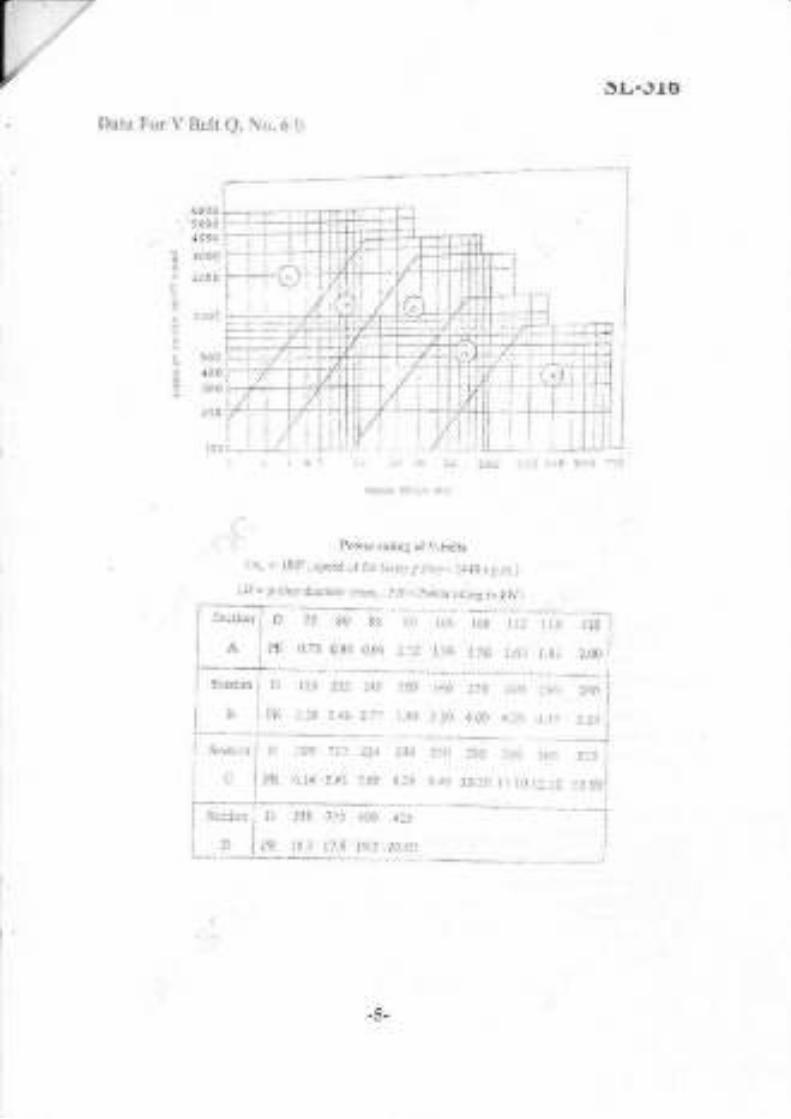
DIJ-JTO
Dar* lor !t Selt Q. lio. 6 b
': 5tt0" lcrn
? looo: ?1lo!fa
r lnoo
6 !C!
; ]oo
?00
: .i t t :_ i::, tt tt ..t)t ,at:.t 10a :!n .i.
at5ior t)tt rrr,l
?ow.r rniint rtV.rda
S,:.:ioi. . D ri 8u .: o: :r. tub I
.. r : ) 1rl,
/\ ,1, ,).,tjdo f...r t.1: rr :50 t4r li 2X
t-'l11 ,ip ::'r L ) :r )0r^
{n, . i8i' r rp.rr,ra lit insle. irjlc,r_ :{40i.t.n:.]
{, = pdl.y t&n.rcr {n!ll . t,.{.. prr.r:1!!! irtr,/) .
-5-

sL-316
D!.n..tioll! ol sl.rld&.t cio,!r.(..idons
llrk -lo;'*ai \liJllWt.!',rn)
I'Iiclirr.rs \ri inxr: lir..hftJlrhl grmett otl ull., a xJr)
A..,'
c
!l
3
t:11
2?
37
I1l
14
'19
:a
ir.5
200
:10fl
5l)0
630
For 'r' bel*
Seri.r !f plcfe.rcd vabs\ ir. !jrc! ci&io$.r\ 1r im) are ir loit.,,r
t3:
::iliu0
llirh dr{:ncier {r}il.r ]lj:!i :i: ::t.l ;ti10t| rt25 4j0 4,iJ
t50 800 900 i0r0
:.,i| tsi tntr iiil.i. .r1. lii,.r 1i
5-1t :l', a0! 61ll
;lif irl
67i liil
'l)?e c, snyi..:r rrrI, x rL hnLI\ p"r rL,f
ir -10 10-l$ t.(i-l{l) Liglt iluty: sgjL1lca-btr.,r.r!-ctntiif gel
p*&!s la$ (!1a io i.5 l1?) nnd co&perrd,
l) M.diuni dut : corle,rrs-fr.1r3 (ab.ee t.J kp_llL,r ihal6 rnrdr!t' k,oL\ pr.tscr ird pi,,,t ,.
drsl'llcclneu, I un,p\
3l l{ervf dr9-; ..!!e}on. rcker cleraton $i
.1.l 1.7 1.1
!.4
Jdn.e
3r':.:" { :lmi hrgri to pircf .l&gu
or rl..* urrIelt Se.tion e ncnEDr..f"rcoce teween p,.tch ler,llelrJ jnside leDBh (en,l 43 56 t, 9:36
-6-

sL-316
I.,ifill,n,I .c.f
Coreetioa fartor for atc ol co$act (V.gloor$ olr bati pLxeys)
Coria.tion ,€.1orrF/ tor bir! Irnglh(1., - noour rar r, tlr 8.h or r!.. .r t, n .m,
Ll
1rg5
r9al
xo32
?*47
215'
22d,tr
u35
1.O2
1,0,t
r-0s
1..0d
r88.
i:.Jn
1,11
1.13
1-14
1.f,o
,,\t2
1 O3
1.04
1.05
r.0?
1.{a
ll,1t
1. t3
1.14
1.l5
r,16
1.r3
t.19
":
l),91)
o.tl0.9:
osu
09s
o.9':
o,,0.98
0,991.00
1_07
1.0f
1.0'r
1.Oi
r.07
10,
1.:l
t.Ld
r.1a
0.&i
0.fl,
0.x)
0.1?
0.1:|f
l).94
o9(
t.96
L00
r.0f
I.05
0.r4
0.16
!.99
1_Orl
3(}18
3r50
3,104:65€
40tJ
4tlsJ.394
4512
49J3
5334
&45
{807
'tacg
;
T
+++
(E-
-7-

sL-317Total No. ofPages : 3Sent
No,
T.E. (Mechanical) (Semester - \z) (Revised)
Examinationo M.ay - 2017
MANUFACTURING ENGINEERING
Sub. Code : 662,15
Day and Date: Friday, 19-05-2017 TotalMaris:100Time : 9.00 a.m. to 1.00 p.m.
Insa:'uctions : 1) All questions are compulsory.
2) Figures to the right ind:.{te fult marks.
3) Assume ifnecessar)- suitable datr and staJe thcm clearly.
4) Use ofnon-programrnable c{lculators is pcrmissble,
SECTION - I
Ql) Solve any trvo:
a) Draw neat sketch olSingle point cutting tool and explain diflerent angles
provided on single point cutting tool. t81
, b) Explain Orthogonal & Oblique Cutting Operarion with neat sketch. [8]
c) Duririg orthogonal tur-ning operation of, following observations were
made. Cutting force(Fh):15kg, Feed force(Pv):6kg, Rake angle(o)=10",Feed(t,)=0.2mm, Chip thikness(t,):0.4mm. Cutting Speed(V):60m/min.
Flnd out,
i) Shear angle.
ii) Worhdone in shear and
iii) Shear strain.
I8l
Q2) Solr e tle lollorringque:tions.
a) Explain concept ofHeat generation in metal cutting & use ofcoolants.[81
OR
a) Explain with sketch various types ofdrill. t81
b) The tool life ofa Single point cuttingtool is 10 minutes when it is operated
at 240m /min. At what speed it should be operated in order to have a tool
181
P.T.O.
lile o1180 minutes. Assume n:0.3

Q3) The component shown in fig. is to be processedSiudy ihe component and prepare:
a) Detaiied process sheet.
b) Tool Laybut.
c\ ( am profile lordrillingoperar,ol.
d) Calculate Production rate per hour..
l-"-.1
sL-317on a single spindle automat.
[181
I
I
!I
IL
-T
__l-
-s8 MR
i15
-r-
t-Raw tltalarial.: i 22 lI Dtr
Mateiial - Al bar of O 22,- All dimen$igns are ia rnm.
SECTION - IIQ4) Design & !rau.neat dimensional drau,i,g in three views with one sectional
' r,iew ofjig for. drilling two holes Q l2 as show-n in figure. 126l.' oR
Design & dr.aw neat dimensional drailing in three r iews wirh one sectionalvierv ofMilling fixture lor face milling of 036 to maintain the heighr of 25nrm.Also Justifi, the selection oflocation, clamping & guiding elenrents.
-2-

sL-317Q5) Solve any two.
a) Explain with sketch nomenclature ofPress Tool. 16l
b) Wdte d€sign considerations for die elenrent. t6lc) explditi?ifferent t pes ofstuippers. t6l
Q6) WllG;'ihot notes on any tkee. t Zl
a) Constflrction & working of CNC.
b) Automatic Tool Changer
c) Modular Tooling System.
d) Comparisol between NC and CNC machines.
<c,e
'i..,:r

Sect J
T.E. (Mechanical Engineering) (part_Ie (Semester _ V)(Revised) Examination, April _ 201g ...
THEORY OF MACHINES - IISub. Code:6d242 , .
Day and Datc : Wedresday, 25 - 4 - 201g Total Nl{rks : 100Time : 10.00 a.m. to 1.00 p.[r.
Inslruclions : 1) All questions : .e cornpulsory.2) Figures to the rigLt irdicrte lull rnar.ks,3) Dra\v nent labcletl skelch $,herever necessarr,-4) ,,\ssu e ifneccssrry suitible ilat:t and state ciearl-1,.5) Use of Non progrrmm,rble calculntor is pornittJ.'
SV-83Total No. of Pages : 3
whele, @: fi.ictior.r angle, 6= shaft argle ancl a= spiral angle
Q1) a)
Q2) a)
Derive an expression lor the centre distance lor a pair ofspiralgears anddefir're the following terms.
tgl0 Nomal.pitch
ii' Arialpirclr
OR
tor m.ixt'runlelficiencl irr case ofspiral gear isProve that the condition
on the driving u,l.reel.
b) Two involute gears o120" pressure angle are in mesh. Tl.re number.ofteeth on pinior.r is 20 and rhe gear rrtiol is l. If the pitch e;r;ssed inmodLrleis 5 mrn and the pitch line spectl is t .: ,nA, ar.u.i,,l aa,lendu_as.standard and equal to one module, fud the maximum-vJo"itv nfsliding. - "-'"ir;i
0+d2
Explain the u,orJ<ing of Diflerential
C)R
Explain the concept of equivalent mass and montentfor gear lrains.
gear ofan autorlobile. I6l
ol iner tja applied
i.'P,T. O.

sv-83b) Fig. 2 b shorvs an epicyclic geartrain. Gear'n" is lixed to the fiame and
is therefore stationary. The alm 'B'and gear' 'C' and 'D' are $'qe to
rotate on the shaft. Gears 'A', 'C'and 'D'have 100, 101 and 99 ievth
respectivel!. Pitch circle diameters ofall are the same so thallhe planet
gear 'P' meshes with all of them. Detenaine the revolutions d'f gears 'C'
Q3) u)
b)
Q4) a)
and 'D' lor a revohttion of the arm 'B' t101
I' .ru t'
Shall' r
lrig' I b
Derive the expression lor gyloscopic conple magni*de. .. t6l
A nvo wheeier of400 rnm wheel ladius is negotiating a tum ofradius 60 m
at speed of '100 km/h. The combined l.rass ofvehicle rvith its rjder is 3 00
kg. The C.G of rider is 0.6 m above ground level. The mai:l'ilroment of
inerlia of engine flyvheel is 0.3 kg-m'? and uoment oliriertia of each
road wheel is I 1<g-m2. lfthe speed ofthe engine is fiie.time the speed of
the wheel and in the sarne direction, trnd the angle ofheel olvehicle [10]
Derive an expression for velocity and acceleration oithe slider of slider
cranl< mechanism. t61
OR
Explair.r dynamically equivalent system to replace connecting |od by a
two mass system.
b) The comrecting rod ofa vefiical reciprocating engine is 2 rr long betr't'een
centles and weights 250 kg. The n:.ass centl e is 800 mm fi on.r the big end
bearing. Wl.ren suspended as a pendulum from the gudgeon pin axis, it
makes 8 complete oscillations in 22 seconds. Calculate the radius ofthe
gyration of the rod about an axis tluough its mass centre. The crank is
400 mm long and rotates at 200 rym. Find the inertia torque ele-ii6d on
the crar.)kshaft u,hen the crank has tumed through 40' Irorn the top dead
centl'e afld the piston is tnoving downw-arcls.
-2-
t10l

SV-83a) Explain direct anclreverse clankmethod forbalancing ofthe radial engine.[6]
OR
Explain what is multi cylinder inline engine. Also explain conditions to
1.rave plimarl, and secordary folces and couple balancing in multi cylinder
in lir.re engir.re.
b) Four masses A, B, C and D as shotvn below are te be balanced. [12]
B C D
Mass (ks.) 30 50 40
I{rrlius (rurr) 180 z4l\ 120 150
The planes containing masses B and C are 300 mn.r apart. The angle
betrveen pla.nes containing B alLd C is 90'. B and C n.rakes angles of210" and 120' respectivel), with D in the same sense.
Find:
i) 1-he niagnitude and the angular position ofnrass A, and
ii) The positions ol planes A and D.
Q6) a)
b)
Explain maximum fluctuation ofenergy and coelficient offluituation ofenergy. I6l
The truning moment diagran lor a multi cylindei' elrgine has been drarvn
Lo a scale 1 rim:600 N-m vertically and 1 mm : 3' horizontally. The
intercepted areas between the outputtorque cur,,e and the meanresistance
line, taken in order from one end, are as follows:
51. -124. -0:. -140. 85. .72 arrd 107 nrm. when the engile is
running at a specd o1'600 r'pm. Ifthe total fluctuation olspeed i159o ofthe rnealr, find the necessary mass ofthe flywheel olradius 0.5 r.n. [101
++
-3-

I
SV-84Total No. of Pages : 3Seat
No.
Total Marks : 100
Instructions : 1) All questions are compulsory.
2) Figures to the right indicate full marks.3) Assume Suitable Data wherever necessary atrd state it Clearly.4) Use ofscientific non programmable calclhtor is permittcd.
Ql) Solve any &ree:
a) Define critical radius ofinsulation. Also derive the equation for oiticalradius ofinsulation fol hollow cylinder. t6l
b) What are the modes ofmass lransfer? ExplainFick's law ofdifhrsion.[6]
c) Air at 90ii flows in a copper tube (k = 384 WmK) of 4 crn innerdiameter aird rvith 0.6 cm thick walls which are heated from_{ibioutsideby w{si at 125"C. A scale of0.3 cm thick is deposited on outeisurfaceqlfl13 tube whose thermal conductivity is 1.75 W/mK. The a'ir and water
-\slde heat transfer coefficients arc 227 and 3605 Wm,K, respectively.i ' Find overall heat tansfer coefficient on the outside area basis. t61
d) A steam pipe is covered with two layers of insulation. The inner layer(k = 0.17 WmK) is 30 mm thick and the outer layer (k= 0.093 WmK) is
50 mm thick. The pipe is made of steel (k = 58 WmK) ar.rd has inner
diameter and outer diameter of 160 and 170 mm, respectively. The
temperature ofsaturated steam is 300"C and The atrbient air is at 50"C.
Ifthe inside and outside heat transfer coelficients are 30 and 5.8 Wr#K,respectively, calculate the rate ofheat loss per unit length ofpipe. 16l
Q2) Solve any two:
a) Steel ball bearings (k = 50 WmK, n = l.3x 10-5 m,/s) having a diameter
of40 mm are heated to a temperature of 650"C and then quenched in atank ofoif4! 55'C, Ifthe heat transfer coefficient between ball-bearings
and qil i$00 WrL-rK. Determine the duration of tine the bearing rnust
_ l:ytn i" an oil to reach a temperature of 200'C. .l I8l
, '.\. P,I:O.')
T.E. (Mechliirical) (Part-IIf (Semester - V) (Revised)
. :. Examination, April - 2018
...i I
HEAT AND MAss TRANSFER ,:.
Sub. Code:66243 .:, -..
Day and Date ; Thursday, 26 - 04 - 2018
Time:10.00 a.m. to 1.00 p.m.

sv-84b) A plate 2 cm thick and 2 cm wide is used to heat a fluid at 30.C. Theheat generation rate inside the plate is 7 x 1 06 Wm3. Detenr.ine heat translercoefficient gmaintain the remperatue of the plate below 1g0"Cdake kfor plat€, 2dWmK. Neglect heat losses from the edge of plate... ISI
c) Dolive the equation for temperature distribution & healiansfer throush, a plane wall with uniform heat generation; also co14tfi this equationln
''1erms of ambient temperature & the hear tr.ansfer coefficient. tg]
Q3) Solve any two:
a) Explain the error estimation oftempemtue measLfement in rhermo-well.[g]b) Derive the expression for temperature distribr.rtion for a shor.t fin with
convective tip.
a',.:-
Q4) Solve any tw6 9f ihe followirg;a) Urve the physical signilicanceof
i) NusseltNumber
)i) Grashoff's Number" iii) Reynolds Number
iv) Prandtl Number
K-!= 30.38x10⁻³ WmK, Pr = 0.699..t' -2-
c) An aluminum alloy fin (k = 200 WmK), 3.5 mm thick and 2.5 cm longprotrudes liom the wall. The base is at 420.C and ambient air temperatureis 30"C. The heat tra;lsfer coefficient may be taken as 11 W/mrK. Findthe heat loss and fin efficiency, ifthe heat loss from the fin tip isnegligible.
t8l
,- [8]
t8l
b) Assuming a man as a cylinder of 40 cm diameter and 1.72 m height withsurface temperature of37.C. Calculate the heat loss from his body whilestanding in wind flowing at 20 kmlu at 17.C. Use following correlation;[g]
Nu = 0.027 Reo 80i Prr/3
The properties offluid at mean film temperature are p = l.l614 kg/m3,?r : 184.6x10, Ns/mr, Pr = 0.707, k: 0.0263 WmK.
c) Estimate the heat transfer rate from 100 watt incandescent bulb at 140.Cto an ambient air at 24"C- Approximate the bulb as 60 cm diametersphere and cAlculate percentage loss by natural convection. Use follqwingcorelation:'r) ,{" '",correlation;
t8lyu: g.60..lcr.prlra
The broiiri2rgperties ofair at 82"C are kinematic viscosity( /):21.46i10i m?/s,
:llowin.,.,!'18

Solve any two ofthe following:
a) Write short$pte on:
! \allliion shape factor
sv-84
*}*l8Il: 18
at
ii), ptate and prove Kirchhoff's Law,..3'-
-'.1-' -a&eb)
"...Iffite Plank's 1aw and derive Stefan Boltzmann law fro&:*P1ank's law. [81
c)' fcalculate the following for an industrial fumace 'i?the
form of blackbody and emitting radiatioas at 2500"C. t8l
I Monochromatic emissive power at wavelength 1.2 um
ii) Wavelength at which emission is maximum
iii) Maximum emissive power
iv) Total emissive power
QO a) Write short notes on:
i) Define Fouling factor and explain causes offouling
1121
ii) Typgi,$Condensation and boiling ,a {\,
,\'J - ,\t--:U) not$r$iiil capacity rate (mxCo) of 2500 WK flow" tt ro;4gf;iouble
pipe..lleat exchanger. It enters at'360'C and leaves at 300"!; Cold fluid
\e{Grs at 30'C and leaves at 200'C. Ifoverall heat tra$fer coelficient
GiIfl is 800 Wm']K, determine the heat exchanger areSr_6qiired for parallel''
and counter flow. ' 16l
+++
,i
ii
,.\)"
-\i-
-3-

Day ard Date ; Friday, 27 - 04 - 2018
Time:10.00 a.m. to 1.00 p.m.
Instructions: 1)
2)
3)
4)
s)
sv-85Total No. ofPages : 4
(Revrsed)
.i1'')
Total Marks I I00
Ql) Solve any Three: t18l
Discusglhe guidelines for the selection of quantitative vatuel$f 'factor
,,-
Sqlgest with j ustification the suitable matelial for the -foil6wing:
i.1 Large Flpvheel
b)
ii) Helical spring
iii) DairyEquipment
c) Discuss the design ofa bell-crank lever
d) Discuss differer.rt types ofstresses in bolt design.
Q2) a) A knuckle joint used to connect two mild steel rods has to transmit a
tersile load of 200 kN. Given: yield point strength of the maierial in
tension 20[N/mm2 and factor of safety - 2. Allowable strg!;s in
compressi.p-rSi! two times the allowable stress in tension, and all@blestressin{hear as 0.707 times that in tension. Design the knuckle loint. [81
.,-r i ..: P,T,O.
cal) (Part -III) (Semester - V)
Examination, April - 2018
MACIIINE DESIGN-I
Sub. Code: 66244
All qucstions are cornpulsory.
Figure\ to (he right indicate full marks.
Make suitrb:e assumptions*herever required and stato them clcd],.
Use of non-programmable calcnlator is permitted.
Draw neat diagrams whereycr ncccssary.

SV-8b)
*j::,^lY:':...,ltlcred to a force of 6.kN and fixed to th"
"r,u*"riymeans of thrqe identica.l bolts as shown in figure 2b. The i"il;;-;;:of olain 6a$^" eiaal an.o/a -,^^rrll1,":l{:l} ::tee
r 3 0 C 8 (S,, =+ o oii_?";, r"", ;""; ; "rI;
Yl;e;;;;;t;;id#lii;ffi
I8l
Figure 2g, sioivs a bracket i
two lrllet welds. Determileto the verlical plate by melns ofof welds if the permissi6li'shear
OR
I8l
Q3) a) What are various types ofkeys? Compare stresses in woodruffkey withflatkey? , . [6]
b) Th.e plgpiller shaft is required to transmit 45 kW power at 5qS 6;. It i. "ho.llow sha* -o.l^ ^f6t.i- ^^-L^- -. -rl.?{?y.ltT"d: "rplain
carbon steel *d,1," d;i;;i;6l,ly. .#. r.
' :,$..N/rnmr. Calculate ihe inside and out.rd; dt"-"*.;;,i;';; iJii;
,'i,6tti
t.,-2-
l
sv_85) Ratio ofan inside diameter 0.6 times the outside diameter.
ii) Ratio,qfgn inside diameter 0.65 times the outside diameter
Detetmindifre o/o saving in material bymodif,ing the ratio.
. Y)- OR
b)-. .Dpsign a bushed-pin rype flexible coupling for comecting a motor shaft\ ^to a compressor. with rhe lollou ing service condirfo$s:
Power to be transmitted : 50kW
Speed of motor shaft : 1000rp.m
Diameter of motor and compressor shaft = 55mm
Bearing pressure on the rubber bush : 0.7 N/mm,
Allowable stress in the pins : 60 Mpa
Allowable shear stress in the keys and shafts = 45 Mpa
Allowable crushing stress in the keys: 60 MPa
Allowable shear stress in the flange material : 15 Mpa
Qa) a) Explain with neat sketches, the stresses induced inhelical spring ofcilqplarcross sedtion. t61
b) Design helical compression spring for a maximum load of 1000 N for
.dgflection of 25 mm using the valve having spring index of 5. The,1)frarimum perrnissible shear stress for spring wire is 420 MPa and modulus
ofrigidity is 84 kN/mnf. Assume squared and ground ends. [101
Assume Whal's Stress factor
WhereC-springindex
SWG l 2 3 4 5
Diam.mm 7 .620 7.010 6.401 5.893 5.3 8s
Q5) a) Discuss Various forms of threads used for power transmission givingtheir reladvemerits andlimitations. t6l
OR.1-t- I i: .,
a) Deriie'an expression for maximum efficiency for square tlreaded screw.
_, 4C-1 0.615
4C-4 C
-J-

sv-8sb) The cutter of machine is pulled by square threaded screw of 55 mm
external diqrpeter and pitch of 10 mm. The operating nut takes thg:axialload of400N on a flat surface of60 mm and 90 mm inten.ral ary{&iernaldiameler respectively. Ifthe coelficient oflriction is 0.15 for all contactsu{f+tib on nut. Detemine power required to rotate operali.a! rut whencUtling speed is 6nr./min. Also find efficiency of the sctbi. IlZl
Q6) a) Explain the step by slep procedure for seleclion of V belt fromManufacturer's Catalogue. t6l
b) It is required to select flat belt drive to connect two tuansmission shafts
rotating at 8001pm and 400 rpr1.r respectively. The centre to centre distance
between the shafts is approximately 3m and the belt drive is open type.The power transmitted by the belt is 30 kW. The load corection factoris 1.3. The belt should operate at velocity between 17.80 mls to 22.90
m/s. The power transmitting capacity ofthe beltpermm width perply at180o arc of contact and at a belt velocity of 5.08 m/s is 0.0147 kW.Select prefened pulley diameters and speci4/ the belt. Refer the tablesgiven below;. .: Ilol
3-Ply 125 40 50 63 76
4 -Ply | 40 a4 50 63 76 90 100 112 t25 152
5 - Pll | 76 100 I 12 125 152
6-Ply | 112 125 152 180 200
For flat pulleys: Series ofpreferred values ofpitch diameters (in mm) are as
follows
Pitch diameter (mm):
200 212 224 236
425 450 47s sW900 1000 -.l4)
125
250
530
150
300
630
160
315
670
190
400
800a.
132 140
265 280
560 600
110 180
355 375
710 750
ddd
-4-
Arc of Contact Factor (Fu)
Standard Widths ofthese belts in mrrt
130 140 150
1.26 t.t9 1.13
160 170
1.08 1.04
180 190 200 .
1.00 0.97 :094

SV-86Total No. ofPages i 3
T.E. (M) (Semester - \| Examination, April - 20I9
CONTROL ENGINEERTNG
Sub. Code: 66241
Day and Date : Thursda1.,25 - 04 - 2019
Time:2.30 p.m. to 5.30 p.m.
Instructions; 1) Allquestions are compulsory.
2) Assume su ita ble data i f rcq u i red and men tion it clearh,.
Ql) a) For the mechanical system shown in Fig. 1a construct grounded chairrepresentation and find equation relating/ to _r and r to y t6l
4 l-IB o2 I \,f;'-6,1 -Trtrdt -r,As 1a
b) Explain mathematical model ofhydraulic system. t61c) Constuct direct and Inverse analog for Electrical circuit shorvn in fig
Find mechanical circuitwith equations. t6l
Total Marks : 100
Seat
No,
PT.O.

Q2) a)
Q3) a)
having r{dth W and length L. . t81
b) Find tlfefirnsfer function for the block diagram shown in ff1t t81
I\,
sv-86What do you mean by linearization ol non-linear function. Explaingeometric, interFetation oferror in the measurement olarea ofa rectangle
Pole zero configuration ofthe overall tuansfer lunction is shovm in fig.Determine its response for unit step input. t81
t
:. .)
1..t ff\ rY\ c\3 \1rq'dY o\xrs
b) The step response ofa second order control, control system is shown
in figure. Determine closed loop transfer function ofthe system. I8l
L\
2-
_)_

sv-86Q4) a) Using Rootn stability cdterion. Determine stabiliq, ofsystem having its
open loop transfer function has poles at s : 0, s : _ 1, s : _ 3 and zeroat s : - { ti&e gain k : 10. ISl
,,..b) Sketi!$foot locus for c(s).H(s)=
,
,1i.r
t :-.
(s+r+7.6)(s+r-:yrB.-l
k(s + 2)I10l
Qs) a)
b)
1000
by characteristic equation s'? + 2s + 3 + /r (s + 2) = O. t6l
Q6) a) Determine state space representation and computer diagram using series
Determine gain margin and phase margin. t10lCalculate break in point and angle ofdeparhrre for control system given
. . 2 (D+ s)programming .r,[r ) =
{ ilt;r(D-4) /(,)
Draw bode plot for transfer function G(s)=
o-o o-o o.odb d5 dh
r (l + 0.ls)0 + 0.00ls) '
t8l
b) Determinqltate space representation and computer diagram using general
D+lProgramming Yltl - , :--:- f (t\- D -9D +24D) 20 I81
,' ,_,
'i'
a

T.E. (Wlechanical) (semester - V) (Revised)a.'Examination, April - 201g
SV-86Total No, ofPages : 3
MANUMCTURING ENGINEERING (PAPti.- IIDSub. Code: 66245
Day and Date : Saturday, 2g _ 04 _ 2018Time ; 9.30 a.m. to 1.30 p.m.
Total Marks : 100
Instructions I l) All questions are computsory,
2) Figures to flre right indicate full marks,3) Assuhe ifnecessary suitable data and state them clearly.4) Use ofnoh programmable calculators is permissible,
SECTION - Il
Ql) Solve any two :
a) Draw neal s&tch of a Single point cuttirlg tool and expJain different
. 3*1..: p:o. ided on singre p-oint cuning tooi
' '"' '"" '^v'drrr urrrc'enr
b] !-rliliOrrt "gonal
& Oblique Cutting Operation witt, n.at rt"tct . 1tjc) Quring_onhogonal ruming operarion of. lollowlng obsenation. were
. -made.
Cutting force (Fh]^= 15 Kg, Feed force lFri:O ig, nurc ungt"iot : tO'. Feed rt r : (
^ i.-...rle,,r, JJ mm. Chip rhikness (r,:.0.4 mm. CurringSpeed (V) = 60 m/min. l-ind our:i) Shearangle. I81
ii) Workdone in shear and
iii) Shear strain.
Q2 ) Solve rhe lollou ing quesrions :
a) Explain concept ofHeat generation in metal cutting & use ofcoolanrs-
t8IOR
a) Explain wit\sketch various tlpes ofdril. _ t8lb) The too-l{ifd,ofa Single point cutting rool is 10 minutes when ir i. ;p;";
a1-240ii7min. At what speed it should be op"rat"d in o.J".d;#;;;;lif€of 180 minutes. Assume n : 0.3. ' t8l
'.) ' tl PT,o,

SV-86Q3) The component shown in fig. is to be processed on a single spindle automat.
{"181
''l' '
.Yt).
Materiai - Al lar oio l2 Ali dimensicns are in mm.
a ,'- t'
. :i:t SECTION - II |-'. ::i- |t\'/
Q4) Desig{@ draw neat dimensional drawing in three views yrisir -one
sectionalviqr&fjig for drilling two holes Q t2 as shown in figure.- *)
' p6lr"-)
OR
Desing & draw neat dimensional drawing in three views with one sectionalview ofMilling fixture for face millirg ofQ36 to maintain the height of25 mm.
Also Justif the selection oflocation, clamphg & guiding elements.
!,/1 t'r
,.:r1
.)
Study the comp.olgnt and prepare :
a) Oetaile.d{&iesssheet.
b) Toolt$out.
c) Qlilprofrle for drilling operation Q8 through
d)')Calculate Production rate per hour.
,'a !
( .\ sr\' I
l
-2-

Q5) Solve any two :
a) Explain *-,i@sketch nomenclature of Press Too1.
b) Write {q-&gi considerations for die element.
c) E)ipl\t*
p{h different types ofstrippers.
..\*
Q6) Wri/e short notes on any tlrree :
a) Construction & working of CNC.
b) Automatic Tool Changer
c) Modular Tooling System.
d) Comparison between NC and CNC machines.
++++
a.
.'a
,...\).,,
,- tL;
SY-86
, *lol,t
i' t6I
t6t..,\t*
' ltzl
, llx.'t
-a
.r:el&'
.,Y-3-

Seatl
N". I
Q2) a) Compare the gear tEins based on speed ratio. power
effi ciency and application.
T.E. (Mechld[icai Engineering) (part - D (Semester - V)Examination, Aprii - _2019
THEORI' OF I}TACHINES.II
Sub. Code:66242
sv-87Total No. ofPagcs : 3
Total Mark! : 100Day and Date : Sat urd ay,27 - 04 - 2019
Time r 2.30 p.m. to 5.30 p,m,
Instmctions : 1) All questions are compulsory.
2) Figures to th€ rightindicatefult marks.
3) Make suita ble assumptions wherever requir€il and state them clearly.il) Use ofnon-prcgrammable calculator is permitted.
O Draw neat diagrams whercver necessary,.
Ql) a) Derive the expression for maximum efficiency in case ofspiral gear [81
OR
Dedve,the equatiofi for cefier distance ofa spiral gear pair .., -
b) A pin ion having J0 reerh drives a gear having g0leeth. The profile ofrhcgears rs rrrvotute with 20 degree pressure angle, t2tririr module and 10mm addendum. Fj[d the lergth ofpath ofcontact, arc ofcontact, contactratio and the maximum vetocib, of sliding iflthe phion rotates at I00r.p.m. tl0l
OR
What do you mean by bnking or the flxing torque ofa gear in epicyclicgear rrainl How can it be nreasurcd? - ' '
16l
transmitted,
I61
P.T,O.

b)sv_87
Tn rn ep icl clic gear train shor.r n in figure 2b. rhe ra heet A is fi red rr heel.wheels B and C are cornporind anJ mounted on one pin. Itthe arm tmal<es 600 .n01) rpm coutter clockwise, find the speed and direction ofrotatioiolwheels D and E. Numberofteerh o" gi*raBi-O r;in *.30,?0,40,25 and 50 respectively.
[101
load disriihirtiistribution on the wheels ifthe car is rouflding a curye at 100 mradiusat 100 kmhr. In\eslipale lorleft tumrounJing.nssunreC t.ll0l
Lhe equation lor narural frequency ofcompound pcnduIum. 16l
fig.2b
Q3) a) Derive an expression for angle ofheel of a fwo wheeler taking a tum. [61
b) A racing car ofmass 2500 kg has a wheel base o12.5 m and a track of1.5 m. The center of gravity of the vehicie is iocated at 0.5 m abovegound and 1,5 m from front axle. The diameler oleach rheel is 0.gomand mass moment ofinerlia 0.77 kg_mz. The drive shaft. engine flpvheeland kansmission are rotating in clockwise direction .ivhen"viewed fro_AonJ wrt! qqrdvalent mass 150 kg with radius ofgiration 15cm. Determine
Q4) a) lve
OR
Derive the equation for velocifj. alld acceleration ofslider in reciprocatingengine mechanism.
16l
b) In a double acting vertical steam engine runDing at 360 rym, cylinderbore diameter is 25cm, stroke is 30 cm, diarneter ofpirton .a i, :.ZScm anci ienglh of conflecting rod is 60 cm. When the crank has turned120' f.om Iop dead center, the pressitre ofsteam at cover end is 35x 101N/ml and at rhe crank end is 3xl0iN/mr. Ifthe masi cf recigocatingparts is 45kg; find piston efforl and iurting moment on the oank shaiifor the given,crank positjon.
. tl0]
-7-

Q5) a) Explain direct and teverse crank method rr", ,, 0",".",.* jrYrll
engines. l.:.'. . t6l,,,: . oR
. E{plain balancing ofsingle revolvingmass in different way.
16lb). . AShaft caries four rotatirg masses A,S,C ana O in lnii oia", ulonn,h". 'shaft ard are concentrated-at radii of 12"^ _d l;;;,j;;; ;;i1;_respectively. The masses at
t,C a:d D ".e
t5 k;; iil;;;*respectively. The planes ofrotalion ofA and g ,." f 5 i*-;""n
"ri #gand C axe l gcm apa .The angle ber'veen rh",.a"
"i ",rlt" nlr:l
"rhe shaft is in compleLe dynaiic balance. derenrine,
il fhe angles berw".r' ,r" ..aii "tO,A
,r,l Oii) The distance between the planes ofrotation ofc and D.iii) The mass at B.
l12l
Q6) a) Explain Coellicient offluctuation ofspeed and Coefficient offluctuatiunofenergy,..... .. t6lU) fhe turyfie;oment diagram fora multi cylinder engine has.been draianto.a sdale lmm= 600 N_m verticatiy anjl ; f ;;;;;;;; il". irligrcepted areas betwe"n a. ourpurio,qu. "u;;#tu.i,#;H*:"- [ine taken in order f.om one end a." as i.ollor.vs;
--'-.*i'r'"*"-^^"
'52- -1)4.- q2--11U.185. 72 and - iQ7p16)
Engine is.running ar b00 rpm. llrhe lolal flucrua on ofspeed is not ruexceed- L50o oflhe mcan. ljnd th" n"...rury.u., o-1,,n!-n"* n".i ",radiqs 0.51n.
l10l
oooo
-3-

sv-88Total No. ofPages : 3
T,E. (Mech.) {Paft - @ (Semester _ V) Examination, May._ 2019
, ..:.:' HEAT AND MASS TRANSFER . .:,'.^1!,, lYrJ.rDD r r(Al\Dr IrI( " ll,
Sub. Code: 66243i. ".." - .:.,. _,
Day and Date r Frida1.,03 - 05 - 2019 i To,alMarks I100
Time: 2.30 p.E. to S.30 p.m,
Instructions : 1)
2)
3)
4)
All questions are compulsory.
Figures to thc fightindicafes full msrks.Assu me suitable data when ever n ecessary anil stat€ it cleady,LIse ofspecific calculators is permitted,
Ql) Solve any three...a) Define c;jrfuil radius ofinsulation. Also derive equation for critical ndius
ofinsuldliin for hollow sphere. -- --.:jr:'i..
b) Defrlr!'overal he"i'o"r".If. "".m"*.1.
Also dedve *, ;$. "rllfoverall hear rransler for a wall har ing ,fr.kn.r. f,
"rJ "*juJ"li, r<.Insloe and outstde heat rran(l.e{ coefficient as h and h". 16lc) ''A steam pipe of s"m tO *a a.s"m oo i.'ir.uiu,J ,i,rn ,.rr",r, ,r,,"0insulatior g<= l.lWmK)the insideand outside fr"ut oun.f",
"o"mli"nare 4650WmrK and 11.5 Wm,K respectiv"ty. fne f ofpip" maieiiut is45WmK if steam temperalure is ZOO.C ana ,.Ui"nt'rr-i.'iOlcDetermine :
16lil Heal Ioss per meter lenglh ofpipe.ii) Interfacetempemtue.
d) A-wall-ofcold storage consist ofthree layers, and outside layerofbricks25cm thick, middle layer of cork, 1Ocm thick una * inn". f uy". oi".*"rrt6cm, the K of materials arc 0.7, 0.04j and 0.72 WmK resp"",l-Jr'rrr"tempeGture ofoutside swface of wall is j0.C and that of imer is _i5.Ccalculate:
t6ti) Healkansferper unit area.ii) -Tqrill2irature at inte{faces at composite wall. ,:..j.;
'
P,T.O.

SV-88Q2) Solve any two.
a) Derive the geneml heat conduction equation in Cafiesian Co_ordinatesystem. Also write the special cases of this equation. Igl
b) Derivi ixpression for temperatwe variation for a solid body with respectto.lime by using lumped heat capacity approach. tg1
c)''.,A long rod ofradius 50cm having K = 1oWmK, which generates heatuniformly within the cylinder at the rate of 0.3X 10⁵wmr. The rod iscooled by convection form it's cylindrical surface at I = 50.C withh : 60W/mrK. Determine the temperatue at the centre and outside surfaceofcylindrical rod.
Q3) Solve any two.
a) Write short notes on:
I81
t8l
i) Explain classification offins with neatsketch.
ii) Fin efiiciency and fin effectiveness.
b) Derive.the expressiotfor temperature distribulion in afin oflrniie iengthwithinsulared end.
l8l
d ,,W.hat are the initial and boundary conditions and their fypes? Explain- - i,,ith suitable examples.
tS1
Q4) Solve any rwo ofthe following. tf6la) Explain in detail the phenomenon ofnaturai and forced convection with
suitable examples.
b) Define Nusselt number and Re;.nolds number and prove that they aredimensiolless numbers.
c) A liquid metal flows at the rate of4 kg/s through a constant heat tlux60 mm inner diameter tube in a nuclear reactor The fluid at 200oC is tobeheated with the tubewali40.C abovethe fluidtemperature. Deteunirethe lelgth dfthue tube required for 25.C rise in bulk fluid temperature.Use t!rc.ionelation, Nu = 0.625 tRe.prf a.
Take p = z.Z rO Eg,m! ,: 3 .l0{ rn: s- Co t30J,kg0C. k t2 W m K and pr _ 0.0 t l.
-

Q5) Solve any two ofthe following.
c) Design considerations for heat exchangers.
d,) Nusselr's rQe'ory o[filmwise condensation.,'-r1 '
., l:i: -
,:"j
sv-88t161
iD Lambertcosine rule
iii) Absorptivity
i9 Refleativity
Q6) Solve any tfuee ofthe following.
a) Derive an expression for efecliveness ofparallel flowheat exchangerJ6lb) Discuss the advantages ofNTU method over LMTD method. t6l
t6l!.;
,it61,\ .,r ";-)
!'i+
a;,,
;.! -
" .:i.\t:i
J.
u:
"11.'
H3t3r
-3-

SeatlNrr. I
SY,39Total No. ofPages | 4
T.E. (Mechairical) (Part - Ill) (Semester - [,.:.
- Examination, May - 2019MACHINE DESIGN - I
Sub. Code : 66244
Q1) Solve any Three:trsi
a) I ist uul steps in,olr cd rn rhe design ofa machjne elemcnt. Discuss uhatis 'working:drawing.
b) SuggestWith justifi cationthe suitabie material lorthe fo
i) BallBearing
rii) Machine bed
L',\ Dairy EquiPment
Draw neat sketch ofa knucklejoint and explain the design procedure.
Discuss design of butt weldjoint under tension.
2) Figu res to the right indicate lull marks,3) Make suitable assumptions wher€ver req uired anal state them cl earlv4, Useofuon-prugramniabiecaicuia:rrrirpermincd,
$ DrarI neatdiagranrs wherever necessary.
Q2) a) Design a tum-buckle to be used. for a stay rope subjected to pul1 of 1gkN. The permissible tensile stress for the steel rods used is 72 il{pa. Thepermissible {ensile and shear str ess for the cast irol1 nut used is 36,i\4paand 30 Ad,4qespectively. Design the tum-bucHe. neter f*te. .. ''' 1t1
: | . i:-.'
..i.:,
". P,T.O,
'..t
Total Marks : 100DayandDate: Molday,06 - 0S - 2019Time : ?.30 p.m. to 5.30 p.m.
Instructions: 1) AII questions are compulsory
c)
d)

sv-89b) The following datais given lor the bracket illustrated in fig.2b. There is
no preload in the bolts. The boits are made ofplain carbon steels 45C8(Sr,:3 80-'Nlrim') and factor ofsafe|/ is 2.5. Using the maximum shear
stres€ the6ry speciB, the size oithe bolts. Refer Table. . , ; t81
P;25kN e:100 mm /, = 150mm 1,=25mm,
bt Figure 2.c shows an eccentrically loaded weldedjoint. DeLermine rhe
we1d.siie.Al1owab1eshearstIessintheweIdis80MPa.
Q3) a) 1 .Discuss design of shaft for rigidiry. t6l
b) It is required to transmit a power of 7 kW at 750 rpm. The angulardeflection ofthe steel ofthe steel spindle tnnsmitting the power sllouldnot be more than 0.35" permeter length. The modulus ofrigidity for the
spindle material is 8z1GPa. Determine the diameterofthe spindle andtheshea. stress induced in it. I10l
OR
b) It is required to design a figid twe of flange coupling to connect twoshafts. The input shaft tuansmits 40 kwpower at 200 rp.m. to the oulputshaft through the coupling. The design torque is 1.5 times the ratedtorque. Given:Allowable stress for key and sltaftis 250 N/nrm, in tensionand compression, and 80 N/nm, in shear. Allowable stess for fla[sematenal lf{N mm:
2-,
OR
Desrgnaton P11ch
(rr-)
MaJ oi or N ommal
diamete(mm)
Core diameter(mm) Iensile Stress Arer
(nunt)
M10 1.50 10 8.160 58.00
Ml2 t.75 t2 9.858 84.30
M16 2.00 16 13.546 157 00
M20 2.50 20 16.933 245.00
w2 2.5 22 18.933 :103
\/124 3 24 20.340 351
\t2'7 2',7 23.320 459

sv-89Q4) a) What are the various t)?es of springs used itr practice? Explain one
r, #J,L::t *:ilf.i,€ ro, nu,,,uottom spring roacled sare.y y.li,"::lfollowingworking conditions, diameter ofvalve seal is 65 mrirloperatingprgssiile is 0.7 N/mm1, maximum pressure when the valiie blol,s offfreeiy is 0.75 N/mm,, maximum Jift ofthe valve when the irressurerises
: . hom 0.7 N/mm: to 0.75 N/mm, is 3.5 mm, maximwir iillowable stress is550 N/mm'?, modulus of rigidig is84, 10r Ni nrm, and rhe spring indexis 6. ll0lStandard wire gauge (SWG) number and coresponding diameter ofspringwire is given in the followingtable.
SWG 4to 3/0 210 0 1
Diameter
(mm)
10.160 9.490 8.839 8.229 7.620
Q5) a) Derive an expression for maximum elliciency for square tkeaded screw. [6]OR
a) What doyou undersrand by overhauling and selflocking ofpor.vei screw?
Hence deduce Lhe cond irion lor selt locking screu.b) Triple start squale threaded screw is used to raise the load'.of SO tN. g
. screw has a nominal diameter of50 mm and a pitch_of Smm, the height
. of nut is 40 mm and coefficient of friction bett'eed nut and screw rs
0- 12. There is no collar friction, find maximum shear stress induced inthe screw and nut threads also find the bearing pressure between screwand nut. [12]
Q6) a) Explain the step by step procedure for selection ofV-belt fromManufacturer's Catalogue.
|efer the tables given below:
-J-
t6lb) It required to seleat a flat- belt drive for a fan running at 360 rpm, which
is driven by l0 kW, i440 rym, moror. The belt drive is open - t1,pe and
space is available for center distance of2 m appx. Belt velocity shouldbe between 17.8 to 22.9 m"/s. The power transmitting capacif ofthe beitper mm width per ply 180o arc ofcontact and at a belt yelocity of5.0gm s is 0.01 l8 kW. I he load correcrion hcror can be taken as L2. Sugge"rpreferreil iliameters for motor and fan pulleys and give.cirinpletespecilications of belri ng.
.. ,; [10]

Pitch diameter@ !-i)3200 212.:ii4 2364oo 425.t 450 4,1s
250 265
500 530
280 300
560 600355 375
670 710
174
315
630/ru 800 900 1000
sv-893-E9lotf&Iajafuqt forpitch diameters in mm.
R6 zs
*5 zc,:.,
:,,,
..., w-.\_.
,'
"1 .:
-
25 40
10 44
76 100
112 125
50 63 76
50 63 76
112 125 152
152 180 200
lt2 125 1,-
-4-
sv-90Total No. ofPages : 4
T.E. (Mechanical) (Part - I[) (Semester - V) (Revise.rl)
Examination, Mny - 2019
MANUFACTURING ENGINEERING',,,t'' Sub. Code : 66245
Day and Date : Wednesday, 08 - 05 - 2019 Total Marlis : 100
Time:2.30 p.m. to 6.30 p.m.
Inslructions i l, {llquestioIs arlj compulsor]..
2) Figures to the right indicate full marks.
3) Assumc suitable datawherever necessatT anil statc itclearly.,l) Use ofnon-programmable calculator is allowed.
QI) Solre anyTwo.
a) Explain mechanics ofchip formation with neat sketch. tgl
b) Explain different types ofrool material and list important propefties oftoolmate al. tgl
c) During machining ofC-40 steel with 0-10-6-6-8-90- 1mm (ORS) shaped
carbide cuttingtool, the following observations have.been made:
Depth of cut :1.5mm
Feed :0.15 mnr/rev
Speed : 120 m/min
Tangential cutting force : 1500 N
Feed thrust force : 900 N
Clrip thicl<ness 0.3 mm
Calculate;
Chip thickness ratio, shear angle, sheax force and normal force at shearplane, friction force and normal force on tool face and coefficisnt offriction. tSl
Seat
No.

sv-90Q2) Solve any Two.
a) Discuss in briefb.pes and selection criteria ofcutting fluid. t8l
b) Drawtool geometry ofdrill and explain nomenclature in detail. IS]
c) The following equatior for tool life has been obtained for HS S tool:
VTo r2.f o 75.dors : C
A b0 mrn. rool Iile was obrained using rhe follou ing cuning condilions:
V l0 m min: I .0.J mm; d - 2.5 mm
Calculate the effect on tool life ilspeed, feed and depth ofcut are togetherincreased by 20% and also ifthey are increased individually by 20%. [8]
Q3) The component shown in Fig. 1 is to beprocessed on a single spindle automat.Study the component and prepare:
a) Detailed process sheet
b) lbol layout
c)' Camprofile for drilling operation
Material : M.S. polish bar $30mm
, t18l
lo . to , to lo
-t4-'J+--+F-Fig. I
R5
_)_

sv-90Q4) Solve any One
a) Design ar@raw a neat dimensional drawirg in three views with- one
section4[vi]w ofa suitable drillingjig for drilling two holes of$.t 8 mmas sboki in Fig. 2. Show clearly the details of location. clanrplng and
guiding oftool. Assume this as a final operation.
",^+('-.r->',
' 1261
tg 2lrLLE5
--..,9r B
.1 FE2
a '' oR
b) Deslgh and draw a dimensional drawing in three views with i:rie sectional
yig,ni of a milling fixture, for producing the 30 mm wide slot at the
cimponent shown in Fig. 3. Show clearly rhe details oflocation. clamping
and setting ofcutter Assume this as a final operation. 126l
,
,..Fig.3
a

sv-90Q5) Solve any two :
a) Explain.different methods ofreducing cutting forces in press worhiqg.[6]
b) Oxplalrfr?ip layout in press working :, t61
c) E$iiiate the blanling force ro cut a blank 25mm wide.qrO)O-- tong
;)&,bm a 1 .5mm thick metal strip, if the ultimate shear.ikess of matedal is- 400N/mmr. Also determine the work Oone lf ttre perintag. p"ret utlonis 25 percent ofmaterial thickness.
16l
Q6) Write short notes on any Three.
a) Automatic tool changer.
b) Milling tooling system.
c) Tool presetting.
d) Construction and working ofDNC.
It2l
,..A:...
I xxx
,a
-4-

/Earr_==_-__-_IN,. I I._l-==-
I,1 ,.
f.f. Mectiali'Jal (Semester - V) F,*-*r_^.. ,',t:,i'
. .,,,.. coNrR:;'E;:r*u;;lIIh'Ap.lr,:diiis
* Sub. Code:66241Day and Date : Tuesday, 24 . 04 - 2018
'::,Time : 10.00 a.nr. to 01.00 p.n. Total Marks : 100Irstructions : 1) AII questions arie cornpulsorl.
!, r tgu res to lhe righ I indicate full ma rks.
Ql) al For the mechanical svsre..p...",tutio,, uijffi :'ffX#"il i?'i?4.construct
grounded chair
sv _ 937Total No. ofpages : 3
161
Pg r+2
hS. L a
using direct analog.
For. rhe elecr rical circuir shown in fitrsrng orrect analog. Sure I b, construcfinechanical
system
&'o -t c-l-
..,.
P.T.o
c) Obtain mathematical model o
/ ta\ / frotational system shoum in figure tc. [6J
t r--__f_F;1_5a+_J __r._r_ *.rffJ
.' l.'
,,
b)
L-

02) at
b)
Q3) a)
R(s) +-.-----)
Detelrnirre Iirrear appr.oximarion SV - 9J7nshr ri rgrc rriangre ti;., ; ;:':;;,:l?::!,'^,"t'0,
ion,,,'"d ro nnd a.ea orrr hcn heigrr: r H Ind b;." ,;;;i.:;:i]t]ftr
tg carculare ronroximarc a ealesl\ecti\ el). f ,rr" rri."i:lra'A'.tslrtoanSlelriangle is i0 unirs antl5 Lrrrirs
Reduce tl.re block shown in figure . I8l
lb and obtain iru,,.l- , Lu,.iio,,. ;g1
Auniry feedbackslsrem with rn inrD",.,,,1n. ,.,p*J" ;;,;;.,iilj:t:l
controller js shor'vn in irgure 3a.n r(t) = u(t) and c(0) = c (0)_= 0 I8l
rr!) I r I
-- +( , ---- l--- r --> ( (a )
$j . :. b.
Fij,:&
cas)
c cs)
ftJ.3 a
b ) Figure 3 b shor.rs pD controll,crirical'1 damped. cl.r:ffii:::rlj:ili,ne vartre orrd .o rrrar s)srern i5
t8]
scs + t.()
-2-

Q0 a) lle cfiaracterjstics equadon ofa teedbach system iss4 + 20s:r + l5s, + 2s 1L = 9. Iind value ofk ifi) System is marginally stable and
r) System is in stable condition.
b)
Qs) u)
G(s)= t(s +1)
,'* ". rlDll
ur lJla\r Bode pi61 Ctrt= 100(s +t)(s+10) (.r+100)
Obtain roor locls lora Lrniry lcedbacl,., .,..-.. :.,
c, ,r-----r - -- "
s'"sLetn u tul opelr ioop rrans ler h'rtcrion
s1s-+6s+25) . tl0l
D!-teuuine value ofh and a, so thatlrequcncl
"t, .d :;:. i;. ., *-ll: Gcdback s1 'rern osciliaLes ar a'rD ltas o}len loop trausfer.fLutction
sv - 937
, .16I
'ii
lt 0l
O6) at A sl stenr is repreren,",l bu (,--- D'l_-...-""r r(r) Di +44Di, constrxct computer cliagram
and state space repr.esentation usil
obtain state space representatio,
:8 direct ProeramminS' Isl
p'og.nn-;ng'[r,r,""ffir|lffili:":ompurer diagra,n usirg paralet;U.mslcr'firnc,ien
tgi
b)
c(t) =_ D +5
,Q) (.D +t) 1o +\@lis-|
a-A.rb..l
-3-


![Belimo Pressure Independent Control Valve Range - …2014.08.21].pdf · Belimo Pressure Independent Control Valve Range - PICCV. V 2 ... Maintenance-free ... Sizing V(valve) = V](https://img.pdfslide.us/doc/110x75/5ab9da0a7f8b9ad5338e6bf1/belimo-pressure-independent-control-valve-range-20140821pdfbelimo-pressure.jpg)