Embed Size (px)
Citation preview
V-Belt and Timing BeltInstallation andMaintenance
Bando USA, Inc.1149 W. Bryn Mawr
Itasca, Illinois 60143(630) 773-6600
(630) 773-6912 FAXwww.bandousa.com
SERVICE EXPRESS 1-800-829-6612
Distributed by:
IntroductionThe purpose of this manual is simple: to help you getmaximum value from your belt drives. As you review thisinformation, you’ll understand why belts are industry’smost widely used means of power transmission. Theyare easy to select, simple to install, and will give youyears of efficient, trouble-free service.
Properly designed and installed belts are virtually main-tenance-free; an occasional retensioning is all that’sneeded to keep them running smoothly. Because beltdrives require so little attention, it’s worth your time tofollow the “common sense” guidelines in this manual.The payoff is maximum belt and sheave life, increaseduptime, and efficient, uninterrupted equipment service.
10 Point V-Belt Installation Check List
1. Turn equipment OFF and lock out powersource.
2. Shorten center distance and remove oldbelts.
3. Inspect and service take-up rails, bearings,and shafts.
4. Inspect and clean sheaves; replace wornand damaged sheaves.
5. Check and correct sheave alignment.
6. Select replacement belts.
7. Lay belts over sheaves; rotate until belts’slack is on the same side.
8. Check final sheave alignment.
9. Increase center distance until belts won’tslip under a full load.
10. Inspect belt drive in 24-48 hours.
IndexPage
V-Belt Installation
Remove Old Belts . . . . . . . . . . . . . . . . . . . . . . .1
Inspect and Service Drive Elements . . . . . . . .1
Inspect/Replace Sheaves . . . . . . . . . . . . . . . . .1
QD® Sheave Installation and Removal . . . . . . .1
Check Sheave Alignment . . . . . . . . . . . . . . . . .2
Select Replacement Belts . . . . . . . . . . . . . . . .2
Install New Belts . . . . . . . . . . . . . . . . . . . . . . . .2
Check Final Sheave Alignment . . . . . . . . . . . . .2
Tension Belts . . . . . . . . . . . . . . . . . . . . . . . . . .2
Inspect Drive in 24-48 Hours . . . . . . . . . . . . . .3
Belt Storage Tips . . . . . . . . . . . . . . . . . . . . . . . . .3
Synchro-Link® Timing Belt Drives . . . . . . . . . . . . .3
Installation . . . . . . . . . . . . . . . . . . . . . . . . . . . . .3
Tensioning . . . . . . . . . . . . . . . . . . . . . . . . . . . . .4
Taper-Lock® Pulley Installation and Removal . .4
Rib Ace® Drives . . . . . . . . . . . . . . . . . . . . . . . . . . .4
Quarter Turn Drives . . . . . . . . . . . . . . . . . . . . . . .5
V-Flat Drives . . . . . . . . . . . . . . . . . . . . . . . . . . . . .5
Idlers
V-Belt . . . . . . . . . . . . . . . . . . . . . . . . . . . . . . . .5
Timing Belt . . . . . . . . . . . . . . . . . . . . . . . . . . . .5
Troubleshooting Guide . . . . . . . . . . . . . . . . . .6 & 7
Troubleshooting Examples . . . . . . . . . . . . . . . . . .8
Bando Product Line . . . . . . . . . .Inside Back Cover
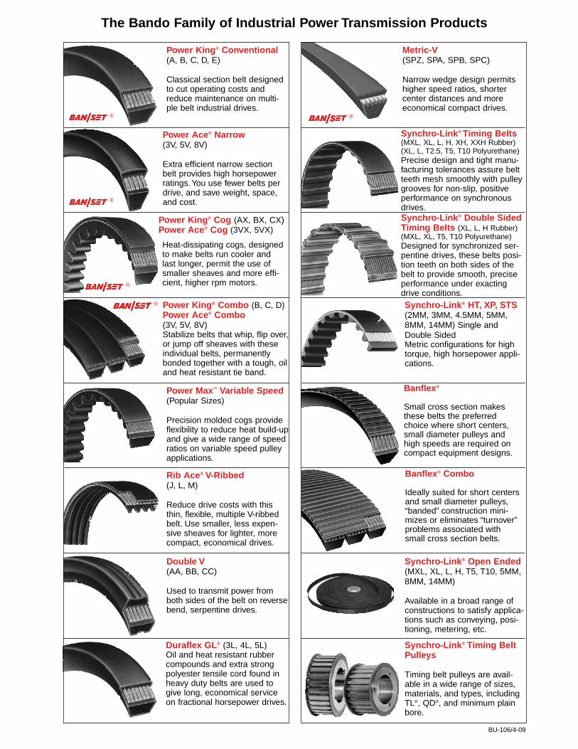
The Bando Family of Industrial Power Transmission Products
Power King® Conventional(A, B, C, D, E)
Classical section belt designedto cut operating costs andreduce maintenance on multi-ple belt industrial drives.
Power Ace® Narrow(3V, 5V, 8V)
Extra efficient narrow sectionbelt provides high horsepowerratings. You use fewer belts perdrive, and save weight, space,and cost.
Power King® Combo (B, C, D)Power Ace® Combo(3V, 5V, 8V)Stabilize belts that whip, flip over,or jump off sheaves with theseindividual belts, permanentlybonded together with a tough, oiland heat resistant tie band.
Heat-dissipating cogs, designedto make belts run cooler andlast longer, permit the use ofsmaller sheaves and more effi-cient, higher rpm motors.
Power Max™ Variable Speed(Popular Sizes)
Precision molded cogs provideflexibility to reduce heat build-upand give a wide range of speedratios on variable speed pulleyapplications.
Rib Ace® V-Ribbed(J, L, M)
Reduce drive costs with thisthin, flexible, multiple V-ribbedbelt. Use smaller, less expen-sive sheaves for lighter, morecompact, economical drives.
Double V(AA, BB, CC)
Used to transmit power fromboth sides of the belt on reversebend, serpentine drives.
Metric-V(SPZ, SPA, SPB, SPC)
Narrow wedge design permitshigher speed ratios, shortercenter distances and moreeconomical compact drives.
Synchro-Link® Timing Belts(MXL, XL, L, H, XH, XXH Rubber)(XL, L, T2.5, T5, T10 Polyurethane)Precise design and tight manu-facturing tolerances assure beltteeth mesh smoothly with pulleygrooves for non-slip, positiveperformance on synchronousdrives.Synchro-Link® Double SidedTiming Belts (XL, L, H Rubber)(MXL, XL, T5, T10 Polyurethane)Designed for synchronized ser-pentine drives, these belts posi-tion teeth on both sides of thebelt to provide smooth, preciseperformance under exactingdrive conditions.Synchro-Link® HT, XP, STS(2MM, 3MM, 4.5MM, 5MM,8MM, 14MM) Single andDouble SidedMetric configurations for hightorque, high horsepower appli-cations.
Synchro-Link® Open Ended(MXL, XL, L, H, T5, T10, 5MM,8MM, 14MM)
Available in a broad range ofconstructions to satisfy applica-tions such as conveying, posi-tioning, metering, etc.
Synchro-Link® Timing BeltPulleys
Timing belt pulleys are avail-able in a wide range of sizes,materials, and types, includingTL®, QD®, and minimum plainbore.
®
®
®
®
Power King® Cog (AX, BX, CX)Power Ace® Cog (3VX, 5VX)
BU-106/4-09
Bando is proud to support and actively participate in these premier industry associations.
®
Duraflex GL® (3L, 4L, 5L)Oil and heat resistant rubbercompounds and extra strongpolyester tensile cord found inheavy duty belts are used togive long, economical serviceon fractional horsepower drives.
Banflex®
Small cross section makesthese belts the preferredchoice where short centers,small diameter pulleys andhigh speeds are required oncompact equipment designs.
Banflex® Combo
Ideally suited for short centersand small diameter pulleys,“banded” construction mini-mizes or eliminates “turnover”problems associated withsmall cross section belts.
1
V-Belt Installation
Caution: Before doing any inspection or mainte-nance on belt drives, turn the equipment off andlock out the power source.
Remove old beltsRemove the drive guard, loosen the take-up, and short-en the center distance between sheaves. This way, theold belts can be removed easily and the new belts canbe installed without damage.
Inspect and service drive elementsRemove rust and dirt from take-up rails, and lubricate asnecessary. Inspect and replace damaged machine ele-ments such as worn bearings and bent shafts. Checkbearings for oil.
Inspect and clean sheaves; replace worn ordamaged sheavesWorn sheave grooves are one of the principal causes ofpremature belt failure. Get your money’s worth from anew set of belts by inspecting the sheaves carefully!
• Clean dirty, dusty, or rusty sheaves. They will impairthe drive’s efficiency and wear out the belt cover.
Feel sheave grooves (wear gloves or use a rag) fornicks or burrs, and file them smooth.
• Belts should ride in sheave grooves so that the top ofthe belt is just above the highest point of the sheave.If the grooves are worn to the point where the belt bot-toms out (a clue: check for shiny groove bottoms), thebelts will slip and burn.
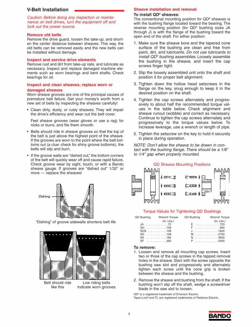
• If the groove walls are “dished out,” the bottom cornersof the belt will quickly wear off and cause rapid failure.Check groove wear by sight, touch, or with a Bandosheave gauge. If grooves are “dished out” 1/32" ormore — replace the sheaves!
Sheave installation and removalTo install QD® sheaves:The conventional mounting position for QD® sheaves iswith the bushing flange located toward the bearing. Thereverse mounting position (for QD® bushing sizes JAthrough J) is with the flange of the bushing toward theopen end of the shaft. For either position:
1. Make sure the sheave bore and the tapered conesurface of the bushing are clean and free frompaint, dirt, and lubricants. Do not use lubricants toinstall QD® bushing assemblies. Loosely assemblethe bushing in the sheave, and insert the capscrews finger tight.
2. Slip the loosely assembled unit onto the shaft andposition it for proper belt alignment.
3. Tighten down the hollow head setscrews in theflange on the key, snug enough to keep it in thedesired position on the shaft.
4. Tighten the cap screws alternately and progres-sively to about half the recommended torque val-ues in the table below. Check alignment andsheave runout (wobble) and correct as necessary.Continue to tighten the cap screws alternately andprogressively to the torque values below. Toincrease leverage, use a wrench or length of pipe.
5. Tighten the setscrew on the key to hold it securelyin place during operation.
NOTE: Don’t allow the sheave to be drawn in con-tact with the bushing flange. There should be a 1/8"to 1/4" gap when properly mounted.
To remove:1. Loosen and remove all mounting cap screws. Insert
two or three of the cap screws in the tapped removalholes in the sheave. Start with the screw opposite thebushing saw slot and progressively and alternatelytighten each screw until the cone grip is brokenbetween the sheave and the bushing.
2. Remove the sheave and bushing from the shaft. If thebushing won’t slip off the shaft, wedge a screwdriverblade in the saw slot to loosen.
QD® is a registered trademark of Emerson Electric.Taper-Lock® and TL are registered trademarks of Reliance Electric.
QD Sheave Mounting Positions
Torque Values for Tightening QD BushingsQD Bushing Wrench Torque QD Bushing Wrench Torque
(In. Lbs.) (In. Lbs.)JA . . . . . . . . . . . . . . .72 E . . . . . . . . . . . . . . . .720SH . . . . . . . . . . . . .108 F . . . . . . . . . . . . . . . .900SDS . . . . . . . . . . . .108 J . . . . . . . . . . . . . . . .1620SD . . . . . . . . . . . . .108 M . . . . . . . . . . . . . . .2700SK . . . . . . . . . . . . .180 N . . . . . . . . . . . . . . .3600SF . . . . . . . . . . . . .360 P . . . . . . . . . . . . . . .5400
“Dishing” of groove sidewalls shortens belt life
Belt should ridelike this
Low riding beltsindicate worn grooves
8
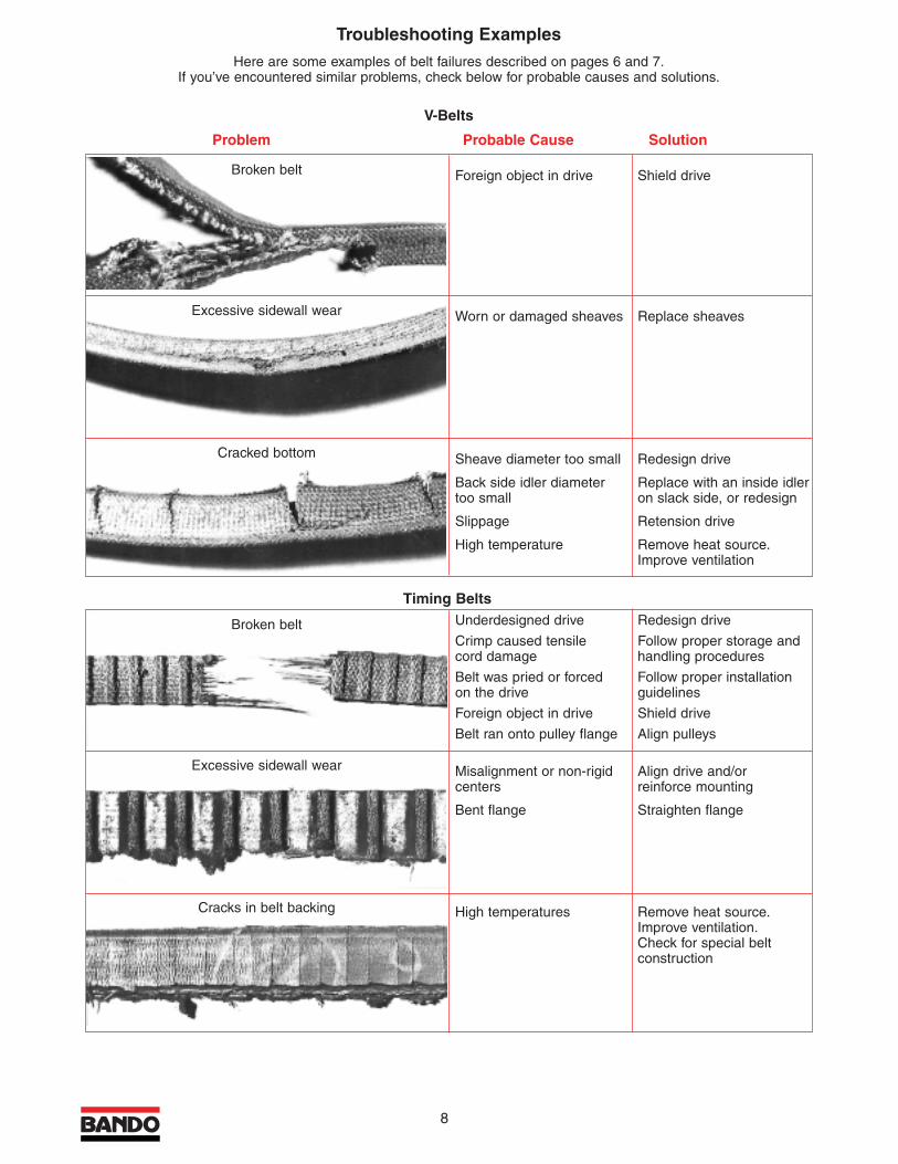
Troubleshooting ExamplesHere are some examples of belt failures described on pages 6 and 7.
If you’ve encountered similar problems, check below for probable causes and solutions.
V-Belts
Problem Probable Cause Solution
Foreign object in drive Shield drive
Worn or damaged sheaves Replace sheaves
Sheave diameter too small Redesign drive
Back side idler diameter Replace with an inside idler too small on slack side, or redesign
Slippage Retension drive
High temperature Remove heat source.Improve ventilation
Broken belt
Excessive sidewall wear
Cracked bottom
Underdesigned drive Redesign drive
Crimp caused tensile Follow proper storage andcord damage handling procedures
Belt was pried or forced Follow proper installationon the drive guidelines
Foreign object in drive Shield drive
Belt ran onto pulley flange Align pulleys
Misalignment or non-rigid Align drive and/orcenters reinforce mounting
Bent flange Straighten flange
High temperatures Remove heat source.Improve ventilation.Check for special beltconstruction
Broken belt
Excessive sidewall wear
Cracks in belt backing
Timing Belts
7
Problem Cause Solution Problem Cause Solution
Drive overtensioned Replace sheavesWorn sheave grooves,belts bottom out
Sheave diameter toosmall
Redesign driveDesign error
Bad bearings Check bearing designand maintenance
Underdesigned or poormaintenance
Drive undertensioned Retension driveBelts slip and causeheat build-up
Sheaves too far out onshaft
Place sheaves as closeto bearings as possible
Design error or obstruc-tion
Hot Bearings
Install back side idleron slack side, or usetiming belt
Arc of contact too small
Clean belts andsheaves, shield drive
Oil or water on belt
Incorrect driveR todriveN ratio
Redesign driveDesign error
Improper DriveN Speed
Belts too long or shortat installation
Check design andselection
Design and/or beltselection error
Belts mismatched atinstallation
Replace all belts withnew belts
Mixed used and newbelts
Replace with beltsfrom the same manu-facturer
Mixed belts from differ-ent manufacturers
Replace sheavesWorn sheave grooves
Installation Problems
Combo (Banded) BeltsTie band cut and/orseparated. Belts ridingout of sheave grooves
Replace sheavesWorn sheaves (Checkwith groove gauge)
Realign sheavesSheave misalignment
Retension driveBelts undertensioned
Shield driveForeign object in drive
All belts separatedfrom tie band
Adjust guardDamage from belt guard
Replace idler sheaveWorn idler sheave
Frayed tie band Remove obstructionand realign drive
Obstruction on machine
Blistered tie band Clean and shield driveForeign materialbetween belts
Cracked belt bottom Retension driveSlippage
Timing BeltsBroken belts Redesign driveUnderdesigned drive
Follow proper storageand handling procedures
Sharp bend damagedtensile cord
Follow proper installation guidelines
Belt was pried or forcedon the drive
Shield driveForeign object in drive
Align pulleysBelt runs onto pulleyflange
Apparent belt stretch Replace pulleys.Install cover if drive isdusty
Reduction of centerdistance or non-rigidmounting
Increase decelerationtime or redesign drive
Pulley teeth poorlymachined or worn
Increase decelerationtime or redesign drive
Sudden equipmentstops
Retension driveBelt doesn’t engagepulley teeth
Tooth shear Redesign drive, installback side idler, or usenext smaller pitch
Less than 6 teeth-in-mesh
Redesign driveExcessive load
Tensile or tooth shearfailure
Increase pulley diame-ter or use next smallerpitch
Pulley diameter toosmall
Protect drive or askBando about specialconstruction belt
Exposure to acid orcaustic atmosphere
Excessive pulley toothwear (on pressureface and/or O.D.)
Reduce installationtension and/orincrease drive loadcarrying capacity
Drive overload and/orexcess belt tension
Use harder material orsurface-harden pulley
Insufficient hardness ofpulley material
Excessive jacket wearbetween teeth, expos-ing tensile cord
Reduce installationtension
Excessive installationtension
Excessive noise Realign driveMisalignment
Reduce tensionExcessive installationtension
Increase drive loadcarrying capacity
Excessive load
Increase pulleydiameter
Pulley diameter toosmall
Cracks in belt backing Improve ventilation,remove heat source,or check with Bandofor special construc-tion belt
High temperatures
Softening of backing Lower ambient temperature, protectfrom oil, or ask Bandoabout special belt con-struction
Excess heat (over200°F) and/or oil
Excessive edge wear Realign drive and/orreinforce mounting
Misalignment or non-rigid centers
Straighten flangeBent flange
Unmounting of flangeor flange wear
Install flange correctlyIncorrect flangeinstallation
Realign driveMisalignment
Troubleshooting Guide
2
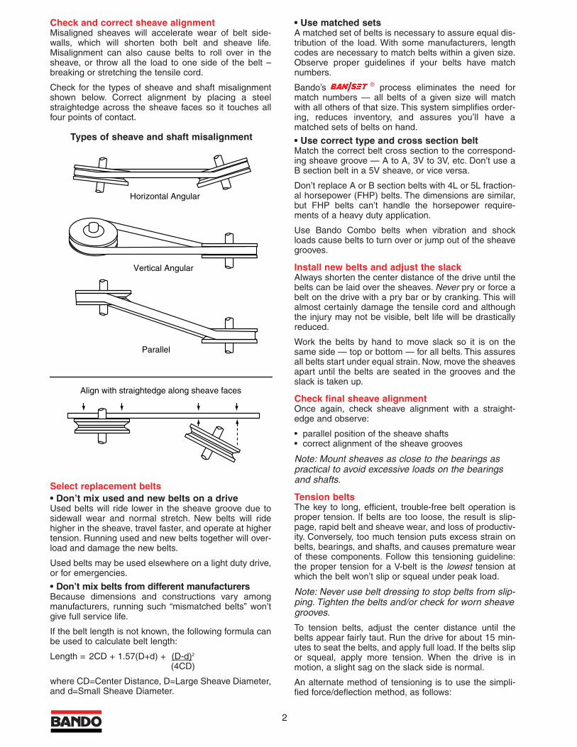
Check and correct sheave alignmentMisaligned sheaves will accelerate wear of belt side-walls, which will shorten both belt and sheave life.Misalignment can also cause belts to roll over in thesheave, or throw all the load to one side of the belt –breaking or stretching the tensile cord.
Check for the types of sheave and shaft misalignmentshown below. Correct alignment by placing a steelstraightedge across the sheave faces so it touches allfour points of contact.
Select replacement belts• Don’t mix used and new belts on a driveUsed belts will ride lower in the sheave groove due tosidewall wear and normal stretch. New belts will ridehigher in the sheave, travel faster, and operate at highertension. Running used and new belts together will over-load and damage the new belts.
Used belts may be used elsewhere on a light duty drive,or for emergencies.
• Don’t mix belts from different manufacturersBecause dimensions and constructions vary amongmanufacturers, running such “mismatched belts” won’tgive full service life.
If the belt length is not known, the following formula canbe used to calculate belt length:
Length = 2CD + 1.57(D+d) + (D-d)2
(4CD)
where CD=Center Distance, D=Large Sheave Diameter,and d=Small Sheave Diameter.
• Use matched setsA matched set of belts is necessary to assure equal dis-tribution of the load. With some manufacturers, lengthcodes are necessary to match belts within a given size.Observe proper guidelines if your belts have matchnumbers.
Bando’s ® process eliminates the need formatch numbers — all belts of a given size will matchwith all others of that size. This system simplifies order-ing, reduces inventory, and assures you’ll have amatched sets of belts on hand.
• Use correct type and cross section beltMatch the correct belt cross section to the correspond-ing sheave groove — A to A, 3V to 3V, etc. Don’t use aB section belt in a 5V sheave, or vice versa.
Don’t replace A or B section belts with 4L or 5L fraction-al horsepower (FHP) belts. The dimensions are similar,but FHP belts can’t handle the horsepower require-ments of a heavy duty application.
Use Bando Combo belts when vibration and shockloads cause belts to turn over or jump out of the sheavegrooves.
Install new belts and adjust the slackAlways shorten the center distance of the drive until thebelts can be laid over the sheaves. Never pry or force abelt on the drive with a pry bar or by cranking. This willalmost certainly damage the tensile cord and althoughthe injury may not be visible, belt life will be drasticallyreduced.
Work the belts by hand to move slack so it is on thesame side — top or bottom — for all belts. This assuresall belts start under equal strain. Now, move the sheavesapart until the belts are seated in the grooves and theslack is taken up.
Check final sheave alignmentOnce again, check sheave alignment with a straight-edge and observe:
• parallel position of the sheave shafts• correct alignment of the sheave grooves
Note: Mount sheaves as close to the bearings aspractical to avoid excessive loads on the bearingsand shafts.
Tension beltsThe key to long, efficient, trouble-free belt operation isproper tension. If belts are too loose, the result is slip-page, rapid belt and sheave wear, and loss of productiv-ity. Conversely, too much tension puts excess strain onbelts, bearings, and shafts, and causes premature wearof these components. Follow this tensioning guideline:the proper tension for a V-belt is the lowest tension atwhich the belt won’t slip or squeal under peak load.
Note: Never use belt dressing to stop belts from slip-ping. Tighten the belts and/or check for worn sheavegrooves.
To tension belts, adjust the center distance until thebelts appear fairly taut. Run the drive for about 15 min-utes to seat the belts, and apply full load. If the belts slipor squeal, apply more tension. When the drive is inmotion, a slight sag on the slack side is normal.
An alternate method of tensioning is to use the simpli-fied force/deflection method, as follows:
Align with straightedge along sheave faces
Parallel
Vertical Angular
Horizontal Angular
Types of sheave and shaft misalignment
6
Problem Cause Solution Problem Cause Solution
V Belts
Rapid failure with novisible reason
Replace sheavesWorn sheave grooves(Check with groovegauge)
Replace all belts witha new set, properlyinstalled
Tensile cords damagedthrough improperinstallation
Redesign driveUnderdesigned drive
Replace all belts withcorrect type, properlyinstalled
Wrong type or crosssection belt
Dry, hard sidewalls.Low adhesion betweenplies. Cracked belt bottom
Remove heat source.Improve ventilation
High temperature
Deterioration of rubber Don’t use belt dress-ing. Clean belts andsheaves with degreas-ing agent or detergentand water. Tensionbelts properly
Belt dressing
Replace sheavesWorn or damagedsheaves
Broken belts Shield driveForeign object in drive
Spin burns Retension driveBelts slip under startingor stalling load
Redesign driveSheave diameter toosmall
Redesign driveLoad miscalculated –drive underdesigned
Cracked bottom Redesign driveSheave diameter toosmall
Replace with an insideidler on slack side, orredesign
Back side idler too small
Retension driveSlippage
Remove heat source.Improve ventilation
High temperature
Extreme cover wear,worn corners
Remove obstructionor realign drive
Belt rubs against guardor other obstruction
Retension driveImproper tension
Clean belt, shield driveDirt on belt
Repair or replacesheaves
Sheaves rusted, sharpcorners or burrs onsheaves
Align sheavesSheaves misaligned
Short Belt Life
Use Bando Combobelts
Shock loads
Position idler on slackside of drive, as closeas possible to driveRsheave
Incorrectly placed flatidler pulley
Install idlerDistance betweenshafts too long
Replace with Bando® belts
Belt lengths uneven
Retension driveBelts too loose
Belt Vibration
Use Bando Combobelts
Severe vibration andshock loads
Shield driveForeign material ingrooves
Realign sheavesMisaligned sheaves
Replace sheavesWorn sheave grooves(Check with groovegauge)
Replace all belts witha new set, properlyinstalled
Tensile cord brokenfrom improperinstallation
Retension driveBelt undertensioned
Position idler on slackside of drive, as closeas possible to driveRsheave
Incorrectly placed flatidler pulley
Belt Turnover
Troubleshooting Guide
Redesign driveSheave diameter toosmall
Shield the driveForeign substancecaught between beltsand sheave
Soft, slick, swollensidewalls. Lowadhesion betweenplies
Clean belts andsheaves with degreas-ing agent or detergentand water. Removesource of oil or grease
Oil or grease on belt orsheave
Cut bottom Check tension andalignment
Belt ran off sheave
Shield driveForeign object in drive
Replace all belts witha new set, properlyinstalled
Improper installation
Belts stretch unequally Realign driveMisaligned drive
Replace all belts witha new set, properlyinstalled
Tensile cord brokenfrom improper installation
Belts stretch equally Check take-up and follow guidelines
Insufficient take-upallowance
Redesign driveOverloaded or underdesigned drive
Belt Stretch
RetensionBelt slip
Realign sheavesMisaligned sheaves
Replace cut edgewith wrapped belt
Wrong belt type
Belt Noise
Retension driveSpin burns
Redesign driveToo few belts
Severe Slippage
3
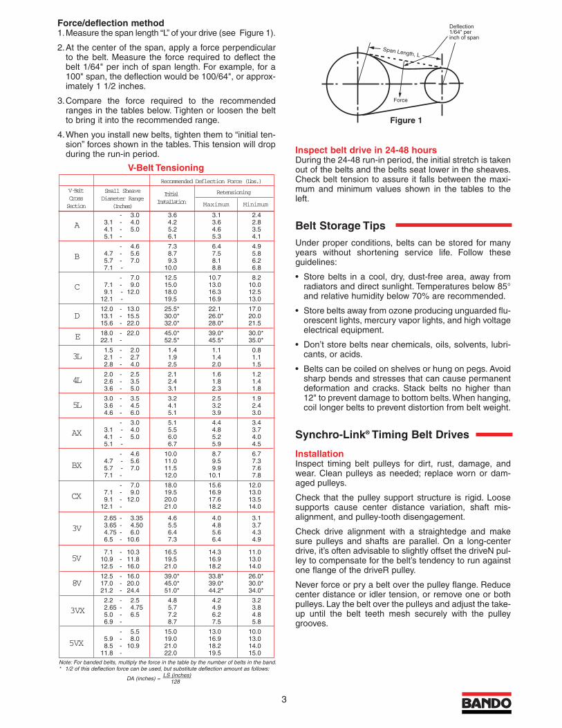
Force/deflection method1.Measure the span length “L” of your drive (see Figure 1).
2.At the center of the span, apply a force perpendicularto the belt. Measure the force required to deflect thebelt 1/64" per inch of span length. For example, for a100" span, the deflection would be 100/64", or approx-imately 1 1/2 inches.
3.Compare the force required to the recommendedranges in the tables below. Tighten or loosen the beltto bring it into the recommended range.
4.When you install new belts, tighten them to “initial ten-sion” forces shown in the tables. This tension will dropduring the run-in period. Inspect belt drive in 24-48 hours
During the 24-48 run-in period, the initial stretch is takenout of the belts and the belts seat lower in the sheaves.Check belt tension to assure it falls between the maxi-mum and minimum values shown in the tables to theleft.
Belt Storage TipsUnder proper conditions, belts can be stored for manyyears without shortening service life. Follow theseguidelines:
• Store belts in a cool, dry, dust-free area, away fromradiators and direct sunlight. Temperatures below 85°and relative humidity below 70% are recommended.
• Store belts away from ozone producing unguarded flu-orescent lights, mercury vapor lights, and high voltageelectrical equipment.
• Don’t store belts near chemicals, oils, solvents, lubri-cants, or acids.
• Belts can be coiled on shelves or hung on pegs. Avoidsharp bends and stresses that can cause permanentdeformation and cracks. Stack belts no higher than12" to prevent damage to bottom belts.When hanging,coil longer belts to prevent distortion from belt weight.
Synchro-Link® Timing Belt Drives
InstallationInspect timing belt pulleys for dirt, rust, damage, andwear. Clean pulleys as needed; replace worn or dam-aged pulleys.
Check that the pulley support structure is rigid. Loosesupports cause center distance variation, shaft mis-alignment, and pulley-tooth disengagement.
Check drive alignment with a straightedge and makesure pulleys and shafts are parallel. On a long-centerdrive, it’s often advisable to slightly offset the driveN pul-ley to compensate for the belt’s tendency to run againstone flange of the driveR pulley.
Never force or pry a belt over the pulley flange. Reducecenter distance or idler tension, or remove one or bothpulleys. Lay the belt over the pulleys and adjust the take-up until the belt teeth mesh securely with the pulleygrooves.
Span Length, L
Force
Deflection 1/64" per inch of span
Note: For banded belts, multiply the force in the table by the number of belts in the band.* 1/2 of this deflection force can be used, but substitute deflection amount as follows:
DA (inches) =LS (inches)
128
- 3.0 3.6 3.1 2.43.1 - 4.0 4.2 3.6 2.84.1 - 5.0 5.2 4.6 3.55.1 - 6.1 5.3 4.1
- 4.6 7.3 6.4 4.94.7 - 5.6 8.7 7.5 5.85.7 - 7.0 9.3 8.1 6.27.1 - 10.0 8.8 6.8
- 7.0 12.5 10.7 8.27.1 - 9.0 15.0 13.0 10.09.1 - 12.0 18.0 16.3 12.5
12.1 - 19.5 16.9 13.0
12.0 - 13.0 25.5* 22.1 17.013.1 - 15.5 30.0* 26.0* 20.015.6 - 22.0 32.0* 28.0* 21.5
18.0 - 22.0 45.0* 39.0* 30.0*22.1 - 52.5* 45.5* 35.0*
1.5 - 2.0 1.4 1.1 0.82.1 - 2.7 1.9 1.4 1.12.8 - 4.0 2.5 2.0 1.5
2.0 - 2.5 2.1 1.6 1.22.6 - 3.5 2.4 1.8 1.43.6 - 5.0 3.1 2.3 1.8
3.0 - 3.5 3.2 2.5 1.93.6 - 4.5 4.1 3.2 2.44.6 - 6.0 5.1 3.9 3.0
- 3.0 5.1 4.4 3.43.1 - 4.0 5.5 4.8 3.74.1 - 5.0 6.0 5.2 4.05.1 - 6.7 5.9 4.5
- 4.6 10.0 8.7 6.74.7 - 5.6 11.0 9.5 7.35.7 - 7.0 11.5 9.9 7.67.1 - 12.0 10.1 7.8
- 7.0 18.0 15.6 12.07.1 - 9.0 19.5 16.9 13.09.1 - 12.0 20.0 17.6 13.5
12.1 - 21.0 18.2 14.0
2.65 - 3.35 4.6 4.0 3.13.65 - 4.50 5.5 4.8 3.74.75 - 6.0 6.4 5.6 4.36.5 - 10.6 7.3 6.4 4.9
7.1 - 10.3 16.5 14.3 11.010.9 - 11.8 19.5 16.9 13.012.5 - 16.0 21.0 18.2 14.0
12.5 - 16.0 39.0* 33.8* 26.0*17.0 - 20.0 45.0* 39.0* 30.0*21.2 - 24.4 51.0* 44.2* 34.0*
2.2 - 2.5 4.8 4.2 3.22.65 - 4.75 5.7 4.9 3.85.0 - 6.5 7.2 6.2 4.86.9 - 8.7 7.5 5.8
- 5.5 15.0 13.0 10.05.9 - 8.0 19.0 16.9 13.08.5 - 10.9 21.0 18.2 14.0
11.8 - 22.0 19.5 15.0
Recommended Deflection Force (Lbs.)
V-BeltCrossSection
A
B
C
D
E
3L
4L
5L
AX
BX
CX
3V
5V
8V
3VX
5VX
Small SheaveDiameter Range
(Inches)
InitialInstallation
Retensioning
Maximum Minimum
V-Belt Tensioning
Figure 1
Rapid sidewall wear Replace sheavesWorn or damagedsheaves
Belt Size 012 019 025 031 037 050 075 100 150 200 300 400 500 600
Belt Width 1/8" 3/16" 1/4" 5/16" 3/8" 1/2" 3/4" 1" 11/2" 2" 3" 4" 5" 6"
MXLMax. .10 .15 .24 .35 .42 .62
Min. .05 .09 .13 .19 .22 .33
XLMax. .42 .55 .66 1.1 1.9
Min. .20 .31 .37 .57 1.0
LMax. 1.3 2.1 2.9 4.7 6.4
Min. 1.0 1.5 2.2 3.4 4.7
HMax. 4.7 6.8 10.4 14.3 22.4
Min. 3.7 5.2 8.2 11.2 17.6
XHMax. 17.7 27.9 39.7 51.0 62.2
Min. 16.3 25.8 36.7 47.0 57.3
XXH Max. 40.5 63.9 90.7 117.2 142.1
Min. 21.5 34.0 48.1 62.3 75.2
4 5
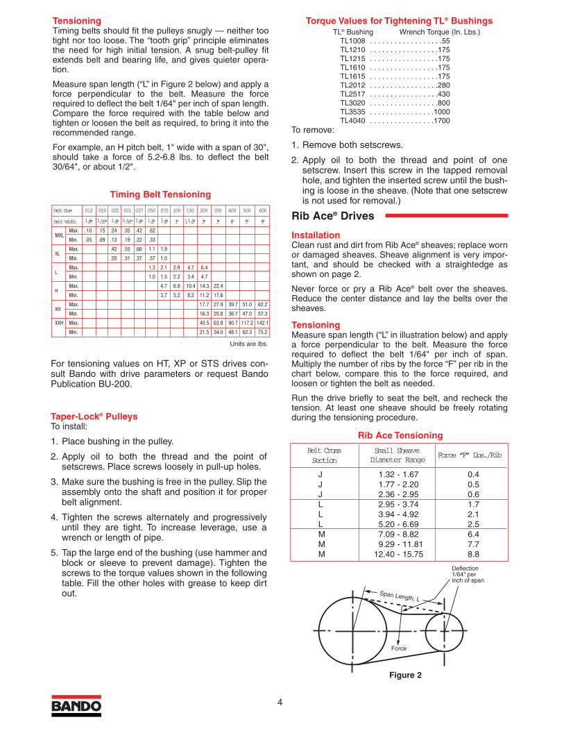
TensioningTiming belts should fit the pulleys snugly — neither tootight nor too loose. The “tooth grip” principle eliminatesthe need for high initial tension. A snug belt-pulley fitextends belt and bearing life, and gives quieter opera-tion.
Measure span length (“L” in Figure 2 below) and apply aforce perpendicular to the belt. Measure the forcerequired to deflect the belt 1/64" per inch of span length.Compare the force required with the table below andtighten or loosen the belt as required, to bring it into therecommended range.
For example, an H pitch belt, 1" wide with a span of 30",should take a force of 5.2-6.8 lbs. to deflect the belt30/64", or about 1/2".
Taper-Lock® PulleysTo install:
1. Place bushing in the pulley.
2. Apply oil to both the thread and the point ofsetscrews. Place screws loosely in pull-up holes.
3. Make sure the bushing is free in the pulley. Slip theassembly onto the shaft and position it for properbelt alignment.
4. Tighten the screws alternately and progressivelyuntil they are tight. To increase leverage, use awrench or length of pipe.
5. Tap the large end of the bushing (use hammer andblock or sleeve to prevent damage). Tighten thescrews to the torque values shown in the followingtable. Fill the other holes with grease to keep dirtout.
Torque Values for Tightening TL® BushingsTL® Bushing Wrench Torque (In. Lbs.)
TL1008 . . . . . . . . . . . . . . . . . .55TL1210 . . . . . . . . . . . . . . . . .175TL1215 . . . . . . . . . . . . . . . . .175TL1610 . . . . . . . . . . . . . . . . .175TL1615 . . . . . . . . . . . . . . . . .175TL2012 . . . . . . . . . . . . . . . . .280TL2517 . . . . . . . . . . . . . . . . .430TL3020 . . . . . . . . . . . . . . . . .800TL3535 . . . . . . . . . . . . . . . .1000TL4040 . . . . . . . . . . . . . . . .1700
To remove:
1. Remove both setscrews.
2. Apply oil to both the thread and point of onesetscrew. Insert this screw in the tapped removalhole, and tighten the inserted screw until the bush-ing is loose in the sheave. (Note that one setscrewis not used for removal.)
Rib Ace® Drives
InstallationClean rust and dirt from Rib Ace® sheaves; replace wornor damaged sheaves. Sheave alignment is very impor-tant, and should be checked with a straightedge asshown on page 2.
Never force or pry a Rib Ace® belt over the sheaves.Reduce the center distance and lay the belts over thesheaves.
TensioningMeasure span length (“L” in illustration below) and applya force perpendicular to the belt. Measure the forcerequired to deflect the belt 1/64" per inch of span.Multiply the number of ribs by the force “F” per rib in thechart below, compare this to the force required, andloosen or tighten the belt as needed.
Run the drive briefly to seat the belt, and recheck thetension. At least one sheave should be freely rotatingduring the tensioning procedure.
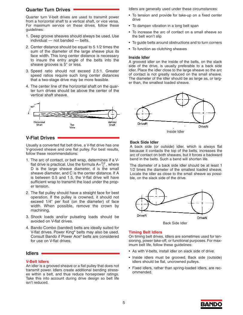
Quarter Turn DrivesQuarter turn V-belt drives are used to transmit powerfrom a horizontal shaft to a vertical shaft, or vice versa.For maximum service on these drives, follow theseguidelines:
1. Deep groove sheaves should always be used. Useindividual — not banded — belts.
2. Center distance should be equal to 5 1/2 times thesum of the diameter of the large sheave plus itsface width. This long center distance is necessaryto insure the entry angle of the belts into thesheave grooves is 5° or less.
3. Speed ratio should not exceed 2.5:1. Greaterspeed ratios require such long center distancesthat a two-stage drive may be more feasible.
4. The center line of the horizontal shaft on the quar-ter turn drives should be above the center of thevertical shaft sheave.
V-Flat DrivesUsually a converted flat belt drive, a V-flat drive has oneV-grooved sheave and one flat pulley. For best results,follow these recommendations:
1. The arc of contact, or belt wrap, determines if a V-flat drive is practical. Use the formula A= , whereD is the large sheave diameter, d is the smallsheave diameter, and C is the center distance. If Ais between 0.5 and 1.5, the V-flat drive will havesufficient wrap to transmit the load under the prop-er tension.
2. The flat pulley should have a straight face for bestoperation. If the pulley is crowned, it should notexceed 1/4" per foot (on the diameter) of facewidth. When possible, remove the crown bymachining.
3. Shock loads and/or pulsating loads should beavoided on V-flat drives.
4. Bando Combo (banded) belts are ideally suited for V-flat drives. Power King® belts may also be used.Consult Bando if Power Ace® belts are consideredfor use on V-flat drives.
Idlers
V-Belt IdlersAn idler is a grooved sheave or a flat pulley that does nottransmit power. Idlers create additional bending stress-es within a belt, and thus reduce horsepower ratings.Take this into account during drive design so belt lifeisn’t reduced.
Idlers are generally used under these circumstances:
• To tension and provide for take-up on a fixed centerdrive
• To dampen vibration in a long belt span
• To increase the arc of contact on a small sheave sothe belt won’t slip
• To guide belts around obstructions and to turn corners
• To function as clutching sheaves
Inside IdlerA grooved idler on the inside of the belts, on the slackside of the drive, is usually preferable to a back sideidler. Place the idler close to the large sheave so the arcof contact is not greatly reduced on the small sheave.The diameter of the idler should be as large as, or larg-er than, the smallest loaded sheave.
Timing Belt IdlersOn timing belt drives, idlers are sometimes used for ten-sioning, power take-off, or functional purposes. For max-imum belt life, follow these guidelines:
• As with V-belts, install idler on slack side of drive.
• Inside idlers must be grooved. Back side (outside)idlers should be flat, uncrowned pulleys.
• Fixed idlers, rather than spring-loaded idlers, are rec-ommended.
Back Side IdlerA back side (or outside) idler, which is always flatbecause it contacts the top of the belts, increases thearc of contact on both sheaves, but it forces a backwardbend in the belts. Such a bend will shorten life.
The diameter of a back side idler should be at least 11/2 times the diameter of the smallest loaded sheave.Locate the idler as close to the small sheave as possi-ble, on the slack side of the drive.
Span Length, L
Force
Deflection 1/64" per inch of span
Belt CrossSection
Small Sheave Diameter Range Force “F” Lbs./Rib
J 1.32 - 1.67 0.4J 1.77 - 2.20 0.5J 2.36 - 2.95 0.6L 2.95 - 3.74 1.7L 3.94 - 4.92 2.1L 5.20 - 6.69 2.5M 7.09 - 8.82 6.4M 9.29 - 11.81 7.7M 12.40 - 15.75 8.8
Rib Ace Tensioning
Timing Belt Tensioning
Units are lbs.
Back Side Idler
Inside Idler
D-dC
For tensioning values on HT, XP or STS drives con-sult Bando with drive parameters or request BandoPublication BU-200.
Figure 2
Belt Size 012 019 025 031 037 050 075 100 150 200 300 400 500 600
Belt Width 1/8" 3/16" 1/4" 5/16" 3/8" 1/2" 3/4" 1" 11/2" 2" 3" 4" 5" 6"
MXLMax. .10 .15 .24 .35 .42 .62
Min. .05 .09 .13 .19 .22 .33
XLMax. .42 .55 .66 1.1 1.9
Min. .20 .31 .37 .57 1.0
LMax. 1.3 2.1 2.9 4.7 6.4
Min. 1.0 1.5 2.2 3.4 4.7
HMax. 4.7 6.8 10.4 14.3 22.4
Min. 3.7 5.2 8.2 11.2 17.6
XHMax. 17.7 27.9 39.7 51.0 62.2
Min. 16.3 25.8 36.7 47.0 57.3
XXH Max. 40.5 63.9 90.7 117.2 142.1
Min. 21.5 34.0 48.1 62.3 75.2
4 5
TensioningTiming belts should fit the pulleys snugly — neither tootight nor too loose. The “tooth grip” principle eliminatesthe need for high initial tension. A snug belt-pulley fitextends belt and bearing life, and gives quieter opera-tion.
Measure span length (“L” in Figure 2 below) and apply aforce perpendicular to the belt. Measure the forcerequired to deflect the belt 1/64" per inch of span length.Compare the force required with the table below andtighten or loosen the belt as required, to bring it into therecommended range.
For example, an H pitch belt, 1" wide with a span of 30",should take a force of 5.2-6.8 lbs. to deflect the belt30/64", or about 1/2".
Taper-Lock® PulleysTo install:
1. Place bushing in the pulley.
2. Apply oil to both the thread and the point ofsetscrews. Place screws loosely in pull-up holes.
3. Make sure the bushing is free in the pulley. Slip theassembly onto the shaft and position it for properbelt alignment.
4. Tighten the screws alternately and progressivelyuntil they are tight. To increase leverage, use awrench or length of pipe.
5. Tap the large end of the bushing (use hammer andblock or sleeve to prevent damage). Tighten thescrews to the torque values shown in the followingtable. Fill the other holes with grease to keep dirtout.
Torque Values for Tightening TL® BushingsTL® Bushing Wrench Torque (In. Lbs.)
TL1008 . . . . . . . . . . . . . . . . . .55TL1210 . . . . . . . . . . . . . . . . .175TL1215 . . . . . . . . . . . . . . . . .175TL1610 . . . . . . . . . . . . . . . . .175TL1615 . . . . . . . . . . . . . . . . .175TL2012 . . . . . . . . . . . . . . . . .280TL2517 . . . . . . . . . . . . . . . . .430TL3020 . . . . . . . . . . . . . . . . .800TL3535 . . . . . . . . . . . . . . . .1000TL4040 . . . . . . . . . . . . . . . .1700
To remove:
1. Remove both setscrews.
2. Apply oil to both the thread and point of onesetscrew. Insert this screw in the tapped removalhole, and tighten the inserted screw until the bush-ing is loose in the sheave. (Note that one setscrewis not used for removal.)
Rib Ace® Drives
InstallationClean rust and dirt from Rib Ace® sheaves; replace wornor damaged sheaves. Sheave alignment is very impor-tant, and should be checked with a straightedge asshown on page 2.
Never force or pry a Rib Ace® belt over the sheaves.Reduce the center distance and lay the belts over thesheaves.
TensioningMeasure span length (“L” in illustration below) and applya force perpendicular to the belt. Measure the forcerequired to deflect the belt 1/64" per inch of span.Multiply the number of ribs by the force “F” per rib in thechart below, compare this to the force required, andloosen or tighten the belt as needed.
Run the drive briefly to seat the belt, and recheck thetension. At least one sheave should be freely rotatingduring the tensioning procedure.
Quarter Turn DrivesQuarter turn V-belt drives are used to transmit powerfrom a horizontal shaft to a vertical shaft, or vice versa.For maximum service on these drives, follow theseguidelines:
1. Deep groove sheaves should always be used. Useindividual — not banded — belts.
2. Center distance should be equal to 5 1/2 times thesum of the diameter of the large sheave plus itsface width. This long center distance is necessaryto insure the entry angle of the belts into thesheave grooves is 5° or less.
3. Speed ratio should not exceed 2.5:1. Greaterspeed ratios require such long center distancesthat a two-stage drive may be more feasible.
4. The center line of the horizontal shaft on the quar-ter turn drives should be above the center of thevertical shaft sheave.
V-Flat DrivesUsually a converted flat belt drive, a V-flat drive has oneV-grooved sheave and one flat pulley. For best results,follow these recommendations:
1. The arc of contact, or belt wrap, determines if a V-flat drive is practical. Use the formula A= , whereD is the large sheave diameter, d is the smallsheave diameter, and C is the center distance. If Ais between 0.5 and 1.5, the V-flat drive will havesufficient wrap to transmit the load under the prop-er tension.
2. The flat pulley should have a straight face for bestoperation. If the pulley is crowned, it should notexceed 1/4" per foot (on the diameter) of facewidth. When possible, remove the crown bymachining.
3. Shock loads and/or pulsating loads should beavoided on V-flat drives.
4. Bando Combo (banded) belts are ideally suited for V-flat drives. Power King® belts may also be used.Consult Bando if Power Ace® belts are consideredfor use on V-flat drives.
Idlers
V-Belt IdlersAn idler is a grooved sheave or a flat pulley that does nottransmit power. Idlers create additional bending stress-es within a belt, and thus reduce horsepower ratings.Take this into account during drive design so belt lifeisn’t reduced.
Idlers are generally used under these circumstances:
• To tension and provide for take-up on a fixed centerdrive
• To dampen vibration in a long belt span
• To increase the arc of contact on a small sheave sothe belt won’t slip
• To guide belts around obstructions and to turn corners
• To function as clutching sheaves
Inside IdlerA grooved idler on the inside of the belts, on the slackside of the drive, is usually preferable to a back sideidler. Place the idler close to the large sheave so the arcof contact is not greatly reduced on the small sheave.The diameter of the idler should be as large as, or larg-er than, the smallest loaded sheave.
Timing Belt IdlersOn timing belt drives, idlers are sometimes used for ten-sioning, power take-off, or functional purposes. For max-imum belt life, follow these guidelines:
• As with V-belts, install idler on slack side of drive.
• Inside idlers must be grooved. Back side (outside)idlers should be flat, uncrowned pulleys.
• Fixed idlers, rather than spring-loaded idlers, are rec-ommended.
Back Side IdlerA back side (or outside) idler, which is always flatbecause it contacts the top of the belts, increases thearc of contact on both sheaves, but it forces a backwardbend in the belts. Such a bend will shorten life.
The diameter of a back side idler should be at least 11/2 times the diameter of the smallest loaded sheave.Locate the idler as close to the small sheave as possi-ble, on the slack side of the drive.
Span Length, L
Force
Deflection 1/64" per inch of span
Belt CrossSection
Small Sheave Diameter Range Force “F” Lbs./Rib
J 1.32 - 1.67 0.4J 1.77 - 2.20 0.5J 2.36 - 2.95 0.6L 2.95 - 3.74 1.7L 3.94 - 4.92 2.1L 5.20 - 6.69 2.5M 7.09 - 8.82 6.4M 9.29 - 11.81 7.7M 12.40 - 15.75 8.8
Rib Ace Tensioning
Timing Belt Tensioning
Units are lbs.
Back Side Idler
Inside Idler
D-dC
For tensioning values on HT, XP or STS drives con-sult Bando with drive parameters or request BandoPublication BU-200.
Figure 2
6
Problem Cause Solution Problem Cause Solution
V Belts
Rapid failure with novisible reason
Replace sheavesWorn sheave grooves(Check with groovegauge)
Replace all belts witha new set, properlyinstalled
Tensile cords damagedthrough improperinstallation
Redesign driveUnderdesigned drive
Replace all belts withcorrect type, properlyinstalled
Wrong type or crosssection belt
Dry, hard sidewalls.Low adhesion betweenplies. Cracked belt bottom
Remove heat source.Improve ventilation
High temperature
Deterioration of rubber Don’t use belt dress-ing. Clean belts andsheaves with degreas-ing agent or detergentand water. Tensionbelts properly
Belt dressing
Replace sheavesWorn or damagedsheaves
Broken belts Shield driveForeign object in drive
Spin burns Retension driveBelts slip under startingor stalling load
Redesign driveSheave diameter toosmall
Redesign driveLoad miscalculated –drive underdesigned
Cracked bottom Redesign driveSheave diameter toosmall
Replace with an insideidler on slack side, orredesign
Back side idler too small
Retension driveSlippage
Remove heat source.Improve ventilation
High temperature
Extreme cover wear,worn corners
Remove obstructionor realign drive
Belt rubs against guardor other obstruction
Retension driveImproper tension
Clean belt, shield driveDirt on belt
Repair or replacesheaves
Sheaves rusted, sharpcorners or burrs onsheaves
Align sheavesSheaves misaligned
Short Belt Life
Use Bando Combobelts
Shock loads
Position idler on slackside of drive, as closeas possible to driveRsheave
Incorrectly placed flatidler pulley
Install idlerDistance betweenshafts too long
Replace with Bando® belts
Belt lengths uneven
Retension driveBelts too loose
Belt Vibration
Use Bando Combobelts
Severe vibration andshock loads
Shield driveForeign material ingrooves
Realign sheavesMisaligned sheaves
Replace sheavesWorn sheave grooves(Check with groovegauge)
Replace all belts witha new set, properlyinstalled
Tensile cord brokenfrom improperinstallation
Retension driveBelt undertensioned
Position idler on slackside of drive, as closeas possible to driveRsheave
Incorrectly placed flatidler pulley
Belt Turnover
Troubleshooting Guide
Redesign driveSheave diameter toosmall
Shield the driveForeign substancecaught between beltsand sheave
Soft, slick, swollensidewalls. Lowadhesion betweenplies
Clean belts andsheaves with degreas-ing agent or detergentand water. Removesource of oil or grease
Oil or grease on belt orsheave
Cut bottom Check tension andalignment
Belt ran off sheave
Shield driveForeign object in drive
Replace all belts witha new set, properlyinstalled
Improper installation
Belts stretch unequally Realign driveMisaligned drive
Replace all belts witha new set, properlyinstalled
Tensile cord brokenfrom improper installation
Belts stretch equally Check take-up and follow guidelines
Insufficient take-upallowance
Redesign driveOverloaded or underdesigned drive
Belt Stretch
RetensionBelt slip
Realign sheavesMisaligned sheaves
Replace cut edgewith wrapped belt
Wrong belt type
Belt Noise
Retension driveSpin burns
Redesign driveToo few belts
Severe Slippage
3
Force/deflection method1.Measure the span length “L” of your drive (see Figure 1).
2.At the center of the span, apply a force perpendicularto the belt. Measure the force required to deflect thebelt 1/64" per inch of span length. For example, for a100" span, the deflection would be 100/64", or approx-imately 1 1/2 inches.
3.Compare the force required to the recommendedranges in the tables below. Tighten or loosen the beltto bring it into the recommended range.
4.When you install new belts, tighten them to “initial ten-sion” forces shown in the tables. This tension will dropduring the run-in period. Inspect belt drive in 24-48 hours
During the 24-48 run-in period, the initial stretch is takenout of the belts and the belts seat lower in the sheaves.Check belt tension to assure it falls between the maxi-mum and minimum values shown in the tables to theleft.
Belt Storage TipsUnder proper conditions, belts can be stored for manyyears without shortening service life. Follow theseguidelines:
• Store belts in a cool, dry, dust-free area, away fromradiators and direct sunlight. Temperatures below 85°and relative humidity below 70% are recommended.
• Store belts away from ozone producing unguarded flu-orescent lights, mercury vapor lights, and high voltageelectrical equipment.
• Don’t store belts near chemicals, oils, solvents, lubri-cants, or acids.
• Belts can be coiled on shelves or hung on pegs. Avoidsharp bends and stresses that can cause permanentdeformation and cracks. Stack belts no higher than12" to prevent damage to bottom belts.When hanging,coil longer belts to prevent distortion from belt weight.
Synchro-Link® Timing Belt Drives
InstallationInspect timing belt pulleys for dirt, rust, damage, andwear. Clean pulleys as needed; replace worn or dam-aged pulleys.
Check that the pulley support structure is rigid. Loosesupports cause center distance variation, shaft mis-alignment, and pulley-tooth disengagement.
Check drive alignment with a straightedge and makesure pulleys and shafts are parallel. On a long-centerdrive, it’s often advisable to slightly offset the driveN pul-ley to compensate for the belt’s tendency to run againstone flange of the driveR pulley.
Never force or pry a belt over the pulley flange. Reducecenter distance or idler tension, or remove one or bothpulleys. Lay the belt over the pulleys and adjust the take-up until the belt teeth mesh securely with the pulleygrooves.
Span Length, L
Force
Deflection 1/64" per inch of span
Note: For banded belts, multiply the force in the table by the number of belts in the band.* 1/2 of this deflection force can be used, but substitute deflection amount as follows:
DA (inches) =LS (inches)
128
- 3.0 3.6 3.1 2.43.1 - 4.0 4.2 3.6 2.84.1 - 5.0 5.2 4.6 3.55.1 - 6.1 5.3 4.1
- 4.6 7.3 6.4 4.94.7 - 5.6 8.7 7.5 5.85.7 - 7.0 9.3 8.1 6.27.1 - 10.0 8.8 6.8
- 7.0 12.5 10.7 8.27.1 - 9.0 15.0 13.0 10.09.1 - 12.0 18.0 16.3 12.5
12.1 - 19.5 16.9 13.0
12.0 - 13.0 25.5* 22.1 17.013.1 - 15.5 30.0* 26.0* 20.015.6 - 22.0 32.0* 28.0* 21.5
18.0 - 22.0 45.0* 39.0* 30.0*22.1 - 52.5* 45.5* 35.0*
1.5 - 2.0 1.4 1.1 0.82.1 - 2.7 1.9 1.4 1.12.8 - 4.0 2.5 2.0 1.5
2.0 - 2.5 2.1 1.6 1.22.6 - 3.5 2.4 1.8 1.43.6 - 5.0 3.1 2.3 1.8
3.0 - 3.5 3.2 2.5 1.93.6 - 4.5 4.1 3.2 2.44.6 - 6.0 5.1 3.9 3.0
- 3.0 5.1 4.4 3.43.1 - 4.0 5.5 4.8 3.74.1 - 5.0 6.0 5.2 4.05.1 - 6.7 5.9 4.5
- 4.6 10.0 8.7 6.74.7 - 5.6 11.0 9.5 7.35.7 - 7.0 11.5 9.9 7.67.1 - 12.0 10.1 7.8
- 7.0 18.0 15.6 12.07.1 - 9.0 19.5 16.9 13.09.1 - 12.0 20.0 17.6 13.5
12.1 - 21.0 18.2 14.0
2.65 - 3.35 4.6 4.0 3.13.65 - 4.50 5.5 4.8 3.74.75 - 6.0 6.4 5.6 4.36.5 - 10.6 7.3 6.4 4.9
7.1 - 10.3 16.5 14.3 11.010.9 - 11.8 19.5 16.9 13.012.5 - 16.0 21.0 18.2 14.0
12.5 - 16.0 39.0* 33.8* 26.0*17.0 - 20.0 45.0* 39.0* 30.0*21.2 - 24.4 51.0* 44.2* 34.0*
2.2 - 2.5 4.8 4.2 3.22.65 - 4.75 5.7 4.9 3.85.0 - 6.5 7.2 6.2 4.86.9 - 8.7 7.5 5.8
- 5.5 15.0 13.0 10.05.9 - 8.0 19.0 16.9 13.08.5 - 10.9 21.0 18.2 14.0
11.8 - 22.0 19.5 15.0
Recommended Deflection Force (Lbs.)
V-BeltCrossSection
A
B
C
D
E
3L
4L
5L
AX
BX
CX
3V
5V
8V
3VX
5VX
Small SheaveDiameter Range
(Inches)
InitialInstallation
Retensioning
Maximum Minimum
V-Belt Tensioning
Figure 1
Rapid sidewall wear Replace sheavesWorn or damagedsheaves
7
Problem Cause Solution Problem Cause Solution
Drive overtensioned Replace sheavesWorn sheave grooves,belts bottom out
Sheave diameter toosmall
Redesign driveDesign error
Bad bearings Check bearing designand maintenance
Underdesigned or poormaintenance
Drive undertensioned Retension driveBelts slip and causeheat build-up
Sheaves too far out onshaft
Place sheaves as closeto bearings as possible
Design error or obstruc-tion
Hot Bearings
Install back side idleron slack side, or usetiming belt
Arc of contact too small
Clean belts andsheaves, shield drive
Oil or water on belt
Incorrect driveR todriveN ratio
Redesign driveDesign error
Improper DriveN Speed
Belts too long or shortat installation
Check design andselection
Design and/or beltselection error
Belts mismatched atinstallation
Replace all belts withnew belts
Mixed used and newbelts
Replace with beltsfrom the same manu-facturer
Mixed belts from differ-ent manufacturers
Replace sheavesWorn sheave grooves
Installation Problems
Combo (Banded) BeltsTie band cut and/orseparated. Belts ridingout of sheave grooves
Replace sheavesWorn sheaves (Checkwith groove gauge)
Realign sheavesSheave misalignment
Retension driveBelts undertensioned
Shield driveForeign object in drive
All belts separatedfrom tie band
Adjust guardDamage from belt guard
Replace idler sheaveWorn idler sheave
Frayed tie band Remove obstructionand realign drive
Obstruction on machine
Blistered tie band Clean and shield driveForeign materialbetween belts
Cracked belt bottom Retension driveSlippage
Timing BeltsBroken belts Redesign driveUnderdesigned drive
Follow proper storageand handling procedures
Sharp bend damagedtensile cord
Follow proper installation guidelines
Belt was pried or forcedon the drive
Shield driveForeign object in drive
Align pulleysBelt runs onto pulleyflange
Apparent belt stretch Replace pulleys.Install cover if drive isdusty
Reduction of centerdistance or non-rigidmounting
Increase decelerationtime or redesign drive
Pulley teeth poorlymachined or worn
Increase decelerationtime or redesign drive
Sudden equipmentstops
Retension driveBelt doesn’t engagepulley teeth
Tooth shear Redesign drive, installback side idler, or usenext smaller pitch
Less than 6 teeth-in-mesh
Redesign driveExcessive load
Tensile or tooth shearfailure
Increase pulley diame-ter or use next smallerpitch
Pulley diameter toosmall
Protect drive or askBando about specialconstruction belt
Exposure to acid orcaustic atmosphere
Excessive pulley toothwear (on pressureface and/or O.D.)
Reduce installationtension and/orincrease drive loadcarrying capacity
Drive overload and/orexcess belt tension
Use harder material orsurface-harden pulley
Insufficient hardness ofpulley material
Excessive jacket wearbetween teeth, expos-ing tensile cord
Reduce installationtension
Excessive installationtension
Excessive noise Realign driveMisalignment
Reduce tensionExcessive installationtension
Increase drive loadcarrying capacity
Excessive load
Increase pulleydiameter
Pulley diameter toosmall
Cracks in belt backing Improve ventilation,remove heat source,or check with Bandofor special construc-tion belt
High temperatures
Softening of backing Lower ambient temperature, protectfrom oil, or ask Bandoabout special belt con-struction
Excess heat (over200°F) and/or oil
Excessive edge wear Realign drive and/orreinforce mounting
Misalignment or non-rigid centers
Straighten flangeBent flange
Unmounting of flangeor flange wear
Install flange correctlyIncorrect flangeinstallation
Realign driveMisalignment
Troubleshooting Guide
2
Check and correct sheave alignmentMisaligned sheaves will accelerate wear of belt side-walls, which will shorten both belt and sheave life.Misalignment can also cause belts to roll over in thesheave, or throw all the load to one side of the belt –breaking or stretching the tensile cord.
Check for the types of sheave and shaft misalignmentshown below. Correct alignment by placing a steelstraightedge across the sheave faces so it touches allfour points of contact.
Select replacement belts• Don’t mix used and new belts on a driveUsed belts will ride lower in the sheave groove due tosidewall wear and normal stretch. New belts will ridehigher in the sheave, travel faster, and operate at highertension. Running used and new belts together will over-load and damage the new belts.
Used belts may be used elsewhere on a light duty drive,or for emergencies.
• Don’t mix belts from different manufacturersBecause dimensions and constructions vary amongmanufacturers, running such “mismatched belts” won’tgive full service life.
If the belt length is not known, the following formula canbe used to calculate belt length:
Length = 2CD + 1.57(D+d) + (D-d)2
(4CD)
where CD=Center Distance, D=Large Sheave Diameter,and d=Small Sheave Diameter.
• Use matched setsA matched set of belts is necessary to assure equal dis-tribution of the load. With some manufacturers, lengthcodes are necessary to match belts within a given size.Observe proper guidelines if your belts have matchnumbers.
Bando’s ® process eliminates the need formatch numbers — all belts of a given size will matchwith all others of that size. This system simplifies order-ing, reduces inventory, and assures you’ll have amatched sets of belts on hand.
• Use correct type and cross section beltMatch the correct belt cross section to the correspond-ing sheave groove — A to A, 3V to 3V, etc. Don’t use aB section belt in a 5V sheave, or vice versa.
Don’t replace A or B section belts with 4L or 5L fraction-al horsepower (FHP) belts. The dimensions are similar,but FHP belts can’t handle the horsepower require-ments of a heavy duty application.
Use Bando Combo belts when vibration and shockloads cause belts to turn over or jump out of the sheavegrooves.
Install new belts and adjust the slackAlways shorten the center distance of the drive until thebelts can be laid over the sheaves. Never pry or force abelt on the drive with a pry bar or by cranking. This willalmost certainly damage the tensile cord and althoughthe injury may not be visible, belt life will be drasticallyreduced.
Work the belts by hand to move slack so it is on thesame side — top or bottom — for all belts. This assuresall belts start under equal strain. Now, move the sheavesapart until the belts are seated in the grooves and theslack is taken up.
Check final sheave alignmentOnce again, check sheave alignment with a straight-edge and observe:
• parallel position of the sheave shafts• correct alignment of the sheave grooves
Note: Mount sheaves as close to the bearings aspractical to avoid excessive loads on the bearingsand shafts.
Tension beltsThe key to long, efficient, trouble-free belt operation isproper tension. If belts are too loose, the result is slip-page, rapid belt and sheave wear, and loss of productiv-ity. Conversely, too much tension puts excess strain onbelts, bearings, and shafts, and causes premature wearof these components. Follow this tensioning guideline:the proper tension for a V-belt is the lowest tension atwhich the belt won’t slip or squeal under peak load.
Note: Never use belt dressing to stop belts from slip-ping. Tighten the belts and/or check for worn sheavegrooves.
To tension belts, adjust the center distance until thebelts appear fairly taut. Run the drive for about 15 min-utes to seat the belts, and apply full load. If the belts slipor squeal, apply more tension. When the drive is inmotion, a slight sag on the slack side is normal.
An alternate method of tensioning is to use the simpli-fied force/deflection method, as follows:
Align with straightedge along sheave faces
Parallel
Vertical Angular
Horizontal Angular
Types of sheave and shaft misalignment
1
V-Belt Installation
Caution: Before doing any inspection or mainte-nance on belt drives, turn the equipment off andlock out the power source.
Remove old beltsRemove the drive guard, loosen the take-up, and short-en the center distance between sheaves. This way, theold belts can be removed easily and the new belts canbe installed without damage.
Inspect and service drive elementsRemove rust and dirt from take-up rails, and lubricate asnecessary. Inspect and replace damaged machine ele-ments such as worn bearings and bent shafts. Checkbearings for oil.
Inspect and clean sheaves; replace worn ordamaged sheavesWorn sheave grooves are one of the principal causes ofpremature belt failure. Get your money’s worth from anew set of belts by inspecting the sheaves carefully!
• Clean dirty, dusty, or rusty sheaves. They will impairthe drive’s efficiency and wear out the belt cover.
Feel sheave grooves (wear gloves or use a rag) fornicks or burrs, and file them smooth.
• Belts should ride in sheave grooves so that the top ofthe belt is just above the highest point of the sheave.If the grooves are worn to the point where the belt bot-toms out (a clue: check for shiny groove bottoms), thebelts will slip and burn.
• If the groove walls are “dished out,” the bottom cornersof the belt will quickly wear off and cause rapid failure.Check groove wear by sight, touch, or with a Bandosheave gauge. If grooves are “dished out” 1/32" ormore — replace the sheaves!
Sheave installation and removalTo install QD® sheaves:The conventional mounting position for QD® sheaves iswith the bushing flange located toward the bearing. Thereverse mounting position (for QD® bushing sizes JAthrough J) is with the flange of the bushing toward theopen end of the shaft. For either position:
1. Make sure the sheave bore and the tapered conesurface of the bushing are clean and free frompaint, dirt, and lubricants. Do not use lubricants toinstall QD® bushing assemblies. Loosely assemblethe bushing in the sheave, and insert the capscrews finger tight.
2. Slip the loosely assembled unit onto the shaft andposition it for proper belt alignment.
3. Tighten down the hollow head setscrews in theflange on the key, snug enough to keep it in thedesired position on the shaft.
4. Tighten the cap screws alternately and progres-sively to about half the recommended torque val-ues in the table below. Check alignment andsheave runout (wobble) and correct as necessary.Continue to tighten the cap screws alternately andprogressively to the torque values below. Toincrease leverage, use a wrench or length of pipe.
5. Tighten the setscrew on the key to hold it securelyin place during operation.
NOTE: Don’t allow the sheave to be drawn in con-tact with the bushing flange. There should be a 1/8"to 1/4" gap when properly mounted.
To remove:1. Loosen and remove all mounting cap screws. Insert
two or three of the cap screws in the tapped removalholes in the sheave. Start with the screw opposite thebushing saw slot and progressively and alternatelytighten each screw until the cone grip is brokenbetween the sheave and the bushing.
2. Remove the sheave and bushing from the shaft. If thebushing won’t slip off the shaft, wedge a screwdriverblade in the saw slot to loosen.
QD® is a registered trademark of Emerson Electric.Taper-Lock® and TL are registered trademarks of Reliance Electric.
QD Sheave Mounting Positions
Torque Values for Tightening QD BushingsQD Bushing Wrench Torque QD Bushing Wrench Torque
(In. Lbs.) (In. Lbs.)JA . . . . . . . . . . . . . . .72 E . . . . . . . . . . . . . . . .720SH . . . . . . . . . . . . .108 F . . . . . . . . . . . . . . . .900SDS . . . . . . . . . . . .108 J . . . . . . . . . . . . . . . .1620SD . . . . . . . . . . . . .108 M . . . . . . . . . . . . . . .2700SK . . . . . . . . . . . . .180 N . . . . . . . . . . . . . . .3600SF . . . . . . . . . . . . .360 P . . . . . . . . . . . . . . .5400
“Dishing” of groove sidewalls shortens belt life
Belt should ridelike this
Low riding beltsindicate worn grooves
8
Troubleshooting ExamplesHere are some examples of belt failures described on pages 6 and 7.
If you’ve encountered similar problems, check below for probable causes and solutions.
V-Belts
Problem Probable Cause Solution
Foreign object in drive Shield drive
Worn or damaged sheaves Replace sheaves
Sheave diameter too small Redesign drive
Back side idler diameter Replace with an inside idler too small on slack side, or redesign
Slippage Retension drive
High temperature Remove heat source.Improve ventilation
Broken belt
Excessive sidewall wear
Cracked bottom
Underdesigned drive Redesign drive
Crimp caused tensile Follow proper storage andcord damage handling procedures
Belt was pried or forced Follow proper installationon the drive guidelines
Foreign object in drive Shield drive
Belt ran onto pulley flange Align pulleys
Misalignment or non-rigid Align drive and/orcenters reinforce mounting
Bent flange Straighten flange
High temperatures Remove heat source.Improve ventilation.Check for special beltconstruction
Broken belt
Excessive sidewall wear
Cracks in belt backing
Timing Belts
IntroductionThe purpose of this manual is simple: to help you getmaximum value from your belt drives. As you review thisinformation, you’ll understand why belts are industry’smost widely used means of power transmission. Theyare easy to select, simple to install, and will give youyears of efficient, trouble-free service.
Properly designed and installed belts are virtually main-tenance-free; an occasional retensioning is all that’sneeded to keep them running smoothly. Because beltdrives require so little attention, it’s worth your time tofollow the “common sense” guidelines in this manual.The payoff is maximum belt and sheave life, increaseduptime, and efficient, uninterrupted equipment service.
10 Point V-Belt Installation Check List
1. Turn equipment OFF and lock out powersource.
2. Shorten center distance and remove oldbelts.
3. Inspect and service take-up rails, bearings,and shafts.
4. Inspect and clean sheaves; replace wornand damaged sheaves.
5. Check and correct sheave alignment.
6. Select replacement belts.
7. Lay belts over sheaves; rotate until belts’slack is on the same side.
8. Check final sheave alignment.
9. Increase center distance until belts won’tslip under a full load.
10. Inspect belt drive in 24-48 hours.
IndexPage
V-Belt Installation
Remove Old Belts . . . . . . . . . . . . . . . . . . . . . . .1
Inspect and Service Drive Elements . . . . . . . .1
Inspect/Replace Sheaves . . . . . . . . . . . . . . . . .1
QD® Sheave Installation and Removal . . . . . . .1
Check Sheave Alignment . . . . . . . . . . . . . . . . .2
Select Replacement Belts . . . . . . . . . . . . . . . .2
Install New Belts . . . . . . . . . . . . . . . . . . . . . . . .2
Check Final Sheave Alignment . . . . . . . . . . . . .2
Tension Belts . . . . . . . . . . . . . . . . . . . . . . . . . .2
Inspect Drive in 24-48 Hours . . . . . . . . . . . . . .3
Belt Storage Tips . . . . . . . . . . . . . . . . . . . . . . . . .3
Synchro-Link® Timing Belt Drives . . . . . . . . . . . . .3
Installation . . . . . . . . . . . . . . . . . . . . . . . . . . . . .3
Tensioning . . . . . . . . . . . . . . . . . . . . . . . . . . . . .4
Taper-Lock® Pulley Installation and Removal . .4
Rib Ace® Drives . . . . . . . . . . . . . . . . . . . . . . . . . . .4
Quarter Turn Drives . . . . . . . . . . . . . . . . . . . . . . .5
V-Flat Drives . . . . . . . . . . . . . . . . . . . . . . . . . . . . .5
Idlers
V-Belt . . . . . . . . . . . . . . . . . . . . . . . . . . . . . . . .5
Timing Belt . . . . . . . . . . . . . . . . . . . . . . . . . . . .5
Troubleshooting Guide . . . . . . . . . . . . . . . . . .6 & 7
Troubleshooting Examples . . . . . . . . . . . . . . . . . .8
Bando Product Line . . . . . . . . . .Inside Back Cover
The Bando Family of Industrial Power Transmission Products
Power King® Conventional(A, B, C, D, E)
Classical section belt designedto cut operating costs andreduce maintenance on multi-ple belt industrial drives.
Power Ace® Narrow(3V, 5V, 8V)
Extra efficient narrow sectionbelt provides high horsepowerratings. You use fewer belts perdrive, and save weight, space,and cost.
Power King® Combo (B, C, D)Power Ace® Combo(3V, 5V, 8V)Stabilize belts that whip, flip over,or jump off sheaves with theseindividual belts, permanentlybonded together with a tough, oiland heat resistant tie band.
Heat-dissipating cogs, designedto make belts run cooler andlast longer, permit the use ofsmaller sheaves and more effi-cient, higher rpm motors.
Power Max™ Variable Speed(Popular Sizes)
Precision molded cogs provideflexibility to reduce heat build-upand give a wide range of speedratios on variable speed pulleyapplications.
Rib Ace® V-Ribbed(J, L, M)
Reduce drive costs with thisthin, flexible, multiple V-ribbedbelt. Use smaller, less expen-sive sheaves for lighter, morecompact, economical drives.
Double V(AA, BB, CC)
Used to transmit power fromboth sides of the belt on reversebend, serpentine drives.
Metric-V(SPZ, SPA, SPB, SPC)
Narrow wedge design permitshigher speed ratios, shortercenter distances and moreeconomical compact drives.
Synchro-Link® Timing Belts(MXL, XL, L, H, XH, XXH Rubber)(XL, L, T2.5, T5, T10 Polyurethane)Precise design and tight manu-facturing tolerances assure beltteeth mesh smoothly with pulleygrooves for non-slip, positiveperformance on synchronousdrives.Synchro-Link® Double SidedTiming Belts (XL, L, H Rubber)(MXL, XL, T5, T10 Polyurethane)Designed for synchronized ser-pentine drives, these belts posi-tion teeth on both sides of thebelt to provide smooth, preciseperformance under exactingdrive conditions.Synchro-Link® HT, XP, STS(2MM, 3MM, 4.5MM, 5MM,8MM, 14MM) Single andDouble SidedMetric configurations for hightorque, high horsepower appli-cations.
Synchro-Link® Open Ended(MXL, XL, L, H, T5, T10, 5MM,8MM, 14MM)
Available in a broad range ofconstructions to satisfy applica-tions such as conveying, posi-tioning, metering, etc.
Synchro-Link® Timing BeltPulleys
Timing belt pulleys are avail-able in a wide range of sizes,materials, and types, includingTL®, QD®, and minimum plainbore.
®
®
®
®
Power King® Cog (AX, BX, CX)Power Ace® Cog (3VX, 5VX)
BU-106/4-09
Bando is proud to support and actively participate in these premier industry associations.
®
Duraflex GL® (3L, 4L, 5L)Oil and heat resistant rubbercompounds and extra strongpolyester tensile cord found inheavy duty belts are used togive long, economical serviceon fractional horsepower drives.
Banflex®
Small cross section makesthese belts the preferredchoice where short centers,small diameter pulleys andhigh speeds are required oncompact equipment designs.
Banflex® Combo
Ideally suited for short centersand small diameter pulleys,“banded” construction mini-mizes or eliminates “turnover”problems associated withsmall cross section belts.