Embed Size (px)
Citation preview
Rules for Classification and Construction V Analysis Techniques
1 Hull Structural Design Analyses
4 Guidelines for Global Strength Analysis of Multipurpose Vessels
Edition 2013

The following Guidelines come into force on 1 May 2013.
Germanischer Lloyd SE
Head Office Brooktorkai 18, 20457 Hamburg, Germany
Phone: +49 40 36149-0 Fax: +49 40 36149-200
www.gl-group.com
"General Terms and Conditions" of the respective latest edition will be applicable (see Rules for Classification and Construction, I - Ship Technology, Part 0 - Classification and Surveys).
Reproduction by printing or photostatic means is only permissible with the consent of Germanischer Lloyd SE.
Published by: Germanischer Lloyd SE, Hamburg
Table of Contents
Section 1 Basic Principles A Application, Scope ...................................................................................................... 1-1 B Strength Analysis ........................................................................................................ 1-2 C Structural Modelling .................................................................................................... 1-3 D Loads and Loading Conditions ................................................................................... 1-4 E Calculation and Evaluation of Results ........................................................................ 1-6
Section 2 Global Strength Analysis A General ....................................................................................................................... 2-1 B Structural Idealization ................................................................................................. 2-2 C Boundary Conditions................................................................................................... 2-9 D Loading Conditions ................................................................................................... 2-10 E Load Cases............................................................................................................... 2-18 F Model Check ............................................................................................................. 2-25 G Evaluation ................................................................................................................. 2-26 H Documentation.......................................................................................................... 2-33 Appendix A............................................................................................................................. 2-40
Section 3 Extended Scope of Analysis A General ....................................................................................................................... 3-1 B Tween Deck Load Cases............................................................................................ 3-1 C Crane Load Cases with Jib in Corner Position ........................................................... 3-1 D Grain Bulkhead Load Cases....................................................................................... 3-2
Rules V Analysis Techniques Part 1 Hull Structural Design Analyses Chapter 4 Guidelines for Global Strength Analysis of Multipurpose Vessels
Table of Contents
Edition 2013 Germanischer Lloyd Page 3

Section 1 Basic Principles A Application, Scope ...................................................................................................... 1-1 B Strength Analysis ........................................................................................................ 1-2 C Structural Modelling .................................................................................................... 1-3 D Loads and Loading Conditions ................................................................................... 1-4 E Calculation and Evaluation of Results ........................................................................ 1-6
A Application, Scope
A.1 These Guidelines specify the procedure for global strength assessment of multipurpose ves-sels (MPV) by means of Finite Element (FE) analysis. Application of this advanced analysis method, amending the standard Rule scope, allows evaluating complex structures using a more refined approach, thus enabling further optimisation of structural designs and material utilisation.
A.2 Multipurpose vessels are ships equipped with appropriate facilities to carry general cargo, heavy cargo, project cargo and containers. Frequently observed characteristics are: • large deck openings and small deck strakes • long cargo holds • heavy lift cranes, generally situated at the ship sides • arrangement of a stability pontoon for heavy lift operations • large uniform distributed loads on tank tops (block loads) • large uniform distributed loads and container stack loads on weather deck covers • close fitted weather deck covers with stoppers at one ship side and if needed, stoppers at the oppo-
site side to limit transverse deformations • transmission of high hatch cover stopper forces into the hatch coaming at port and starboard sides • arrangement of tween deck covers at different vertical positions
A.3 The structural analysis is to be carried out on the basis of permissible stresses in accordance with GL Rules for Hull Structures (I-1-1).
A.4 Section 1 of these Guidelines outlines basic principles governing the FE analysis.
A.5 Section 2 provides detailed guidance for a global strength analysis of multipurpose vessels, using a finite element model of the entire vessel. A global FE analysis focuses on global stresses and deformations.
A.6 Computer programs used for finite element analyses have to be generally acknowledged and accepted. All finite element programs that yield results to the satisfaction of Germanischer Lloyd are con-sidered recognised.
A.7 Required fatigue strength assessment is to be based on GL Guidelines for Fatigue Strength Analyses of Ship Structures (V-1-2).
Rules V Analysis Techniques Part 1 Hull Structural Design Analyses Chapter 4 Guidelines for Global Strength Analysis of Multipurpose Vessel
Section 1 Basic Principles
Edition 2013 Germanischer Lloyd Page 1–1
B Strength Analysis
B.1 In general, a strength analysis comprises the following steps: • identifying the objective, type and extent of the analysis • modelling the ship’s structure and specifying appropriate boundary conditions • specifying load cases and the associated applied loads • solving the system of equations • evaluating and assessing the results
B.2 Regarding structural modelling, boundary conditions and loading, certain simplifications are possible or necessary, depending on the objective of the analysis and the type of structure to be ana-lysed.
B.3 In ship structural analyses, deformations and stresses can usually be subdivided into the fol-lowing categories, depending on the structural conditions: • global deformations and stresses of the hull girder and the primary structural members • local deformations and stresses of primary and secondary structural members • locally increased stresses in structural details and discontinuities
B.4 Global deformations and stresses
B.4.1 The structural response of the hull girder and the primary structural members under normal, shear, bending and torsional loads is characterised by global (i. e., large area) deformations and stresses. Furthermore, crane load cases are important and need to be analysed.
B.4.2 Primary structural members of multipurpose vessels comprise floors, bottom girders, side and deck transverses, stringers, longitudinal and transverse deck strips, deck girders, and crane supporting members and associated components, each including the effective part of the plating and stiffeners.
B.4.3 The resulting stresses are nominal stresses, i. e., stresses that also result from integral quanti-ties of sectional forces and moments and from cross-sectional properties. Global nominal stresses gener-ally include the effective breadths, but not locally increased stresses.
B.5 Local deformations and stresses
B.5.1 In secondary structural members local loads can give rise to additional local deformations and stresses.
B.5.2 Secondary structural members comprise all frames, stiffeners, longitudinals, beams and the effective breadth of plating as well as the associated tripping and supporting brackets. Their bending, shear and torsional stiffness must be accounted for.
B.5.3 The effective plate breadth shall be taken into account.
B.5.4 The resulting stresses are nominal stresses which are to be superimposed on global stresses.
B.6 Locally increased stresses
B.6.1 Locally increased stresses in structural details and discontinuities have to be separately as-sessed for fatigue strength. Here, a distinction is made between three types of stresses: • maximum stress in the notch root • structural or hot spot stress, defined alternatively for welded joints • stress at crack tips. Special parameters are used to assess this stress
Rules V Analysis Techniques Part 1 Hull Structural Design Analyses Chapter 4 Guidelines for Global Strength Analysis of Multipurpose Vessel
Section 1 Basic Principles
Edition 2013 Germanischer Lloyd Page 1–2
B.6.2 Under realistic load assumptions for typical structural shipbuilding details, the maximum stress in the notch root, e. g., the stress in the rounded edges of cut-outs, may exceed the elastic limit of the material. Instead of the nonlinear notch stress σ and the associated strain ε, the notch stress σk can be determined and assessed for normal cases under the assumption of linear elastic material behaviour. For very sharp notches, the local supporting effect of the material can be considered with a correspondingly enlarged notch radius.
B.6.3 In complex welded structures, only the stress increase as a result of the structural geometry is generally considered in the analysis, whilst that caused by the weld toe is considered during the assess-ment. This leads to the structural or hot spot stress σs at welds, and this is determined under the assump-tion of elastic material behaviour.
B.6.4 Apart from a direct calculation of locally increased stresses, it is possible to use catalogued stress concentration factors or FAT classes. When using concentration factors and FAT classes, the as-sociated nominal stresses have to be determined with sufficient accuracy in accordance with their defini-tion. Moreover, the ranges of application and validity for the catalogued data are to be observed.
B.6.5 Fatigue strength requirements are given in GL Rules for Hull Structures (I-1-1), Section 20. Assessment procedures are specified in GL Guidelines for Fatigue Strength Analyses of Ship Structures (V-1-2).
C Structural Modelling
C.1 Types of structural models
C.1.1 Global model of the hull
A global model of the hull girder is normally used for the global strength analysis of the entire hull girder and its primary structural components. For 3D modelling of all primary structural components, loads can be applied realistically, and the structural behaviour of complex ship structures, including interactions between individual components, can be taken into account, see Section 2.
To obtain a realistic load transfer into the ship structure for crane load cases it is necessary to incorporate simplified models of the crane columns for load application.
C.1.2 Local models
Local models are used for the strength analysis of secondary or special components and structural de-tails. Usually, the investigation focuses mainly on the analysis of local structural behaviour and/or locally increased stresses in structural details and discontinuities.
C.2 Elements used for structural modelling
C.2.1 Selecting the type of element used primarily depends on the objective of the analysis. The characteristics of the selected element type have to be suitable to reflect with sufficient accuracy the stiff-ness of the structure and the stresses to be analysed.
C.2.2 Usually, the following types of elements are used for strength calculations of ship structures: • truss elements (1D elements with only axial stiffness) • beam elements (1D elements with axial, shear, bending and torsional stiffness) • plane stress elements (PSE), (2D elements with membrane stiffness in the plane, but without out-of-
plane bending stiffness) • plate and shell elements (2D elements with membrane, bending and torsional stiffness) • boundary and spring elements.
When using different element types, attention shall be paid to the compatibility of the displacement func-tions as well as the transferability of boundary loads and stresses, particularly when coupling elements with and without bending stiffness.
Rules V Analysis Techniques Part 1 Hull Structural Design Analyses Chapter 4 Guidelines for Global Strength Analysis of Multipurpose Vessel
Section 1 Basic Principles
Edition 2013 Germanischer Lloyd Page 1–3
C.3 Checks of the model
The geometry of the modelled structure, the chosen elements, the associated material characteristics as well as the applied boundary conditions have to be checked systematically to eliminate errors.
D Loads and Loading Conditions
D.1 General notes
D.1.1 In the following, a general procedure for the selection of loading conditions and related load cases is given. Due to the nature of MPVs, this has to be adapted to the individual ship design and the ship’s operational procedures in compliance with the ship’s loading manual. The selection of relevant loading conditions and load cases should be agreed upon with GL.
D.1.2 Relevant loads for global strength analyses of ship structures can generally be classified into the following types: • static (stillwater) loads from the light ship weight, from the ship’s cargo and from the hydrostatic
pressures caused by buoyancy and tank contents • wave-induced loads, i.e., hydrodynamic pressures, loads from accelerated masses and tank con-
tents, as well as internal and external hydrodynamic impact forces and other variable loads from the ship's operation, e.g., from the action of cranes, stability pontoons, etc.
• loads on bow and stern structures caused by slamming
D.1.3 Selection and generation of load cases to be analysed shall be done in such a way that, with respect to the sum of the forces and moments, either fully balanced load cases are created or clearly defined, realistic sectional forces and/or deformations are obtained at model boundaries and/or supports.
D.1.4 Since several load components mentioned are stochastic and selecting and obtaining relevant load cases may be complex, there are simplified procedures that can be used for practical cases. More-over, there are special procedures to determine wave-induced loads, and these procedures can also be applied to obtain other stochastic loads.
D.2 Simplified procedures
D.2.1 Under this approach, selected (deterministic) load cases are considered that are decisive for the strength of the structural areas under analysis. In general, these load cases consist of unfavourable, but physically meaningful, combinations of diverse load effects. To assess fatigue strength, load cases are to be selected to generate both maximum and minimum stresses at critical locations.
D.2.2 In general seagoing load cases represent unfavourable loading conditions combined with the following unfavourable wave situations: • waves from astern and ahead causing vertical hull girder bending and local loads on the ship’s fore-
body • oblique waves from astern and waves from ahead for the ship in its upright position (relevant for
container loading conditions)
D.2.3 In accordance with the scope of work, several load cases resulting from defined loading condi-tions for MPVs have to be generated, such as: • Harbour loading conditions: calculate maximum inward and outward deflections of hatch coaming
tops to determine clearances of deflection limiters. Their clearances shall be sufficient to allow hatch cover operations under all harbour loading conditions.
• Crane load cases causing maximum crane moments for crane outreaches to port and starboard side for open, closed and partly closed hatch covers.
• Loading conditions causing high loads on weather deck hatch covers to obtain seagoing load cases in combination with large roll angles leading to large deformations of hatch coaming tops and severe
Rules V Analysis Techniques Part 1 Hull Structural Design Analyses Chapter 4 Guidelines for Global Strength Analysis of Multipurpose Vessel
Section 1 Basic Principles
Edition 2013 Germanischer Lloyd Page 1–4
transverse strength conditions (racking). If coaming deformations are within limits of the deflection limiters, no contact forces occur. Otherwise, contact forces are to be calculated. These evaluations have to consider the limited inward and outward movements.
• Conventional container loading condition, to calculate seagoing load cases causing maximum and minimum vertical and horizontal bending moments and maximum and minimum torsional moments. The load cases are to be selected according to GL Guidelines for Global Strength Analysis of Con-tainer Ships (V-1-1).
• Block loading condition, to evaluate the strength of the ship’s bottom structure • Loads on the ship’s bow and stern, causing high global stresses in the longitudinal structure of the
transition region between hold ends and the fore and aft ship.
These loading conditions and related load cases are summarized in Section 2, Table 2.6 – 2.8. A distinc-tion is made between mandatory and optional cases.
D.2.4 Applied load components and associated load combination factors are specified in GL Rules for Hull Structures (I-1-1).
D.2.5 With regard to the situation of waves from astern and/or ahead, load cases "ship on wave crest" and "ship in wave trough" have to be analysed, whereby the position of the crest or trough is to be varied. External pressures shall correspond to the phase relations between ship and wave. Moreover, vertical and longitudinal acceleration components shall be applied to obtain an unfavourable effect on the ship’s mass distribution and on the cargo or tank contents.
D.2.6 Situations with oblique waves from astern or ahead for the ship in its upright position have to be chosen such that the maximum torsional or horizontal bending moments are applied at varying posi-tions along the hull girder, whilst the vertical bending moment exhibits values that are generally reduced in accordance with their peak values. Furthermore, the associated vertical and longitudinal acceleration components which unfavourably affect the ship’s mass distribution and the ship’s cargo and/or tank con-tents shall be applied.
D.2.7 Situations of the rolling ship are to be selected to cause maximum transverse accelerations. Vertical and horizontal acceleration components which unfavourably affect the ship’s mass distribution and the ship’s cargo and/or tank contents shall be applied.
D.3 Special procedures
D.3.1 Alternatives to the simplified procedure based on selected (deterministic) load cases are spe-cial procedures suitable for the consideration of the wave-induced ship motions and loads. For specified irregular waves, there are two possibilities to calculate motions and loads: • computations in the frequency domain and assessments using spectral method • computations in the time domain and assessments using numerical simulations
Natural seaways are usually characterized by energy spectra. Here, the use of the Pierson-Moskowitz spectrum is recommended. Results shall be assessed statistically, whilst considering the frequency of occurrence of seaways, cargo distributions, ship courses and ship speeds.
D.3.2 For computations in the frequency domain, the first step is to determine the structural re-sponse to harmonic elementary waves, in the form of transfer functions which apply for each case of a particular cargo distribution, ship speed and heading relative to the wave direction. Here, a sufficiently large number of wave frequencies shall be considered to capture resonance peaks of structural response. For a specified natural seaway, the spectrum of the structural response depends on the transfer function and the wave spectrum.
D.3.3 For computations in the time domain, the loading process shall be generated in a suitable manner, based on characteristics of the considered wave spectrum. The analysed time domain for the structural response shall be selected long enough to accurately perform the subsequent statistical evalua-tion with respect to the expected values.
D.3.4 The structural response for a natural seaway is to be determined for a representative selection of waves, cargo distributions, ship headings and ship speeds, and these shall be selected with reference
Rules V Analysis Techniques Part 1 Hull Structural Design Analyses Chapter 4 Guidelines for Global Strength Analysis of Multipurpose Vessel
Section 1 Basic Principles
Edition 2013 Germanischer Lloyd Page 1–5
to their frequency of occurrence and the structural response to be assessed. For waves, long-term statis-tics of the North Atlantic should generally be used. If the analysis does not specifically account for ship headings and ship speeds, a uniform distribution of the ship’s courses and a 2/3 maximum speed can be assumed. For loading conditions, see D.2.2. The statistical assessment of structural response is to be based on the probability level specified in GL Rules for Hull Structures (I-1-1).
D.4 Modelling the loads
D.4.1 All loads have to be modelled realistically. Distributed loads shall be converted to equivalent nodal forces. If necessary, modelling of the structure has to be adapted to modelling of the loads.
D.4.2 If boundary deformations derived from coarse models of large structural areas are applied to local models, the correspondingly interpolated values shall be specified for intermediate nodes. In addi-tion, loads acting within the local structural area are to be applied if they are relevant.
D.5 Load input check
D.5.1 Input data of the loads shall be checked thoroughly for errors. As is the case for structural geometry, the effectiveness of this check can be increased considerably using suitable checking pro-grams and visualizations of data.
D.5.2 It is particularly important to check the sums of forces and moments. For balanced load cases, it is to be ensured that residual forces and moments are negligibly small.
D.5.3 The checks performed have to be documented.
E Calculation and Evaluation of Results
E.1 Plausibility of results
E.1.1 Before and during the evaluation, all results shall be examined for plausibility. This involves, in particular, visual presentation and checking of deformations and stresses to see whether their magni-tudes lie within the expected range and whether their distributions are meaningful with respect to the loads and boundary conditions or supports.
E.1.2 Furthermore, it should be checked whether forces and moments at supports lie within the ex-pected order of magnitude or whether they can be neglected, as appropriate for the modelling used.
E.1.3 For local models with specified boundary deformations transferred from the global model, it is necessary to check whether stresses near boundaries correspond to the two associated models.
E.2 Deformations
E.2.1 Structural deformations should generally be plotted for a plausibility check of the results. For a three-dimensional representation, it has to be observed that the direction of the deformation is clearly defined.
E.2.2 Generally, an additional evaluation of deformations is to be performed for the top of coaming. Movements of hatch covers relative to the ship structure as well as movements relative to each other have to be documented as well.
E.3 Stresses
E.3.1 Stresses have to be checked with respect to permissible values, as defined in GL Rules for Hull Structures (I-1-1), Section 5. The corresponding stress category is to be observed, see B.3 to B.6. If necessary, missing stress components caused by the selected models and element types have to be superimposed.
Rules V Analysis Techniques Part 1 Hull Structural Design Analyses Chapter 4 Guidelines for Global Strength Analysis of Multipurpose Vessel
Section 1 Basic Principles
Edition 2013 Germanischer Lloyd Page 1–6
E.3.2 For the stress evaluation, simplifications in the model in relation to the real structure have to be included in the assessment.
E.3.3 In models with relatively coarse meshes, the reduced effective breadth has to be considered if applicable. Furthermore, local stress increases at existing structural details and discontinuities shall be included in the assessment if their effect has not been considered separately.
E.3.4 The assessment should be carried out using utilisation factors, which are defined as the ratio of existing stress and permissible stress. Result tables should be set up and sorted according to their utilisation factors.
E.3.5 For analyses that are based on nonlinear material properties, local strains shall generally also be determined and assessed in addition to local elastic-plastic stresses.
E.4 Buckling strength
Safety against buckling failure is to be determined by considering all calculated stress components in the assessed member area, based on criteria given in GL Rules for Hull Structures (I-1-1), Section 3. The buckling analysis of stiffeners has to account for the effective breadth of the associated plating.
E.5 Fatigue strength
E.5.1 Fatigue strength aspects shall generally be taken into account in the assessment of ship struc-tures, owing to the cyclic stresses that are usually present. In strength analyses for specified load cases, a simplified assessment can be performed if load cases according to D.2 are chosen, such that maximum stress ranges in the components under consideration are approximately attained. Calculation of fatigue strength is then to be carried out on the basis of GL Rules for Hull Structures (I-1-1), Section 20.
E.5.2 MPV structural members to be assessed for fatigue strength have to be selected according to the structural arrangement characteristics of the individual ship. In general, fatigue strength calculations have to be carried out for hatch corners, side shell longitudinals (if applicable), large openings and cut-outs in members subject to cyclic loads and for the welded joints of these members. Furthermore, effects of the integrated crane columns into the ship structure has to be investigated
E.5.3 In assessing stresses with regard to fatigue strength, the stress type has to be considered, i.e., whether stress calculations with the chosen model yield nominal stresses or locally increased struc-tural or notch stresses.
E.5.4 For this kind of assessment, it is recommended to apply utilisation factors; these factors are based on the ratio of maximum actual stress range to permissible stress, see also the GL Guidelines for Fatigue Strength Analyses of Ship Structures (V-1-2).
E.6 Presentation of the results
E.6.1 Results obtained and conclusions made on the basis of these investigations shall be clearly and completely documented.
E.6.2 Documentation can take the form of plots and lists. Lists are necessary if a graphical presenta-tion of results is insufficiently accurate. Extensive lists shall be sorted, for example, according to utilisation factors.
Rules V Analysis Techniques Part 1 Hull Structural Design Analyses Chapter 4 Guidelines for Global Strength Analysis of Multipurpose Vessel
Section 1 Basic Principles
Edition 2013 Germanischer Lloyd Page 1–7

Section 2 Global Strength Analysis A General ....................................................................................................................... 2-1 B Structural Idealization ................................................................................................. 2-2 C Boundary Conditions................................................................................................... 2-9 D Loading Conditions ................................................................................................... 2-10 E Load Cases............................................................................................................... 2-18 F Model Check ............................................................................................................. 2-25 G Evaluation ................................................................................................................. 2-26 H Documentation.......................................................................................................... 2-33 Appendix A............................................................................................................................. 2-40
A General
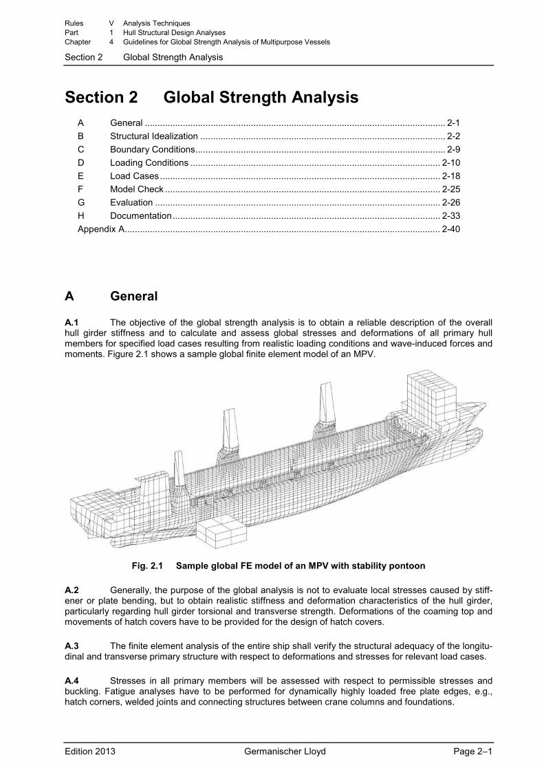
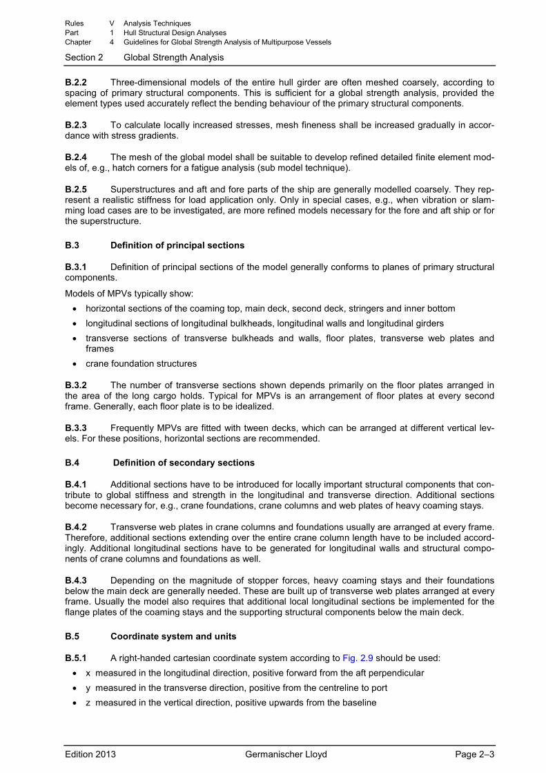
A.1 The objective of the global strength analysis is to obtain a reliable description of the overall hull girder stiffness and to calculate and assess global stresses and deformations of all primary hull members for specified load cases resulting from realistic loading conditions and wave-induced forces and moments. Figure 2.1 shows a sample global finite element model of an MPV.
Fig. 2.1 Sample global FE model of an MPV with stability pontoon
A.2 Generally, the purpose of the global analysis is not to evaluate local stresses caused by stiff-ener or plate bending, but to obtain realistic stiffness and deformation characteristics of the hull girder, particularly regarding hull girder torsional and transverse strength. Deformations of the coaming top and movements of hatch covers have to be provided for the design of hatch covers.
A.3 The finite element analysis of the entire ship shall verify the structural adequacy of the longitu-dinal and transverse primary structure with respect to deformations and stresses for relevant load cases.
A.4 Stresses in all primary members will be assessed with respect to permissible stresses and buckling. Fatigue analyses have to be performed for dynamically highly loaded free plate edges, e.g., hatch corners, welded joints and connecting structures between crane columns and foundations.
Rules V Analysis Techniques Part 1 Hull Structural Design Analyses Chapter 4 Guidelines for Global Strength Analysis of Multipurpose Vessels
Section 2 Global Strength Analysis
Edition 2013 Germanischer Lloyd Page 2–1
A.5 Tools used for finite element calculations and subsequent evaluations shall be based on rec-ognised software. All programs that can show results to the satisfaction of GL are considered recognised.
B Structural Idealization
B.1 Model characteristics
B.1.1 To solve the essential strength characteristics of MPVs and the pertinent strength related problems, it is necessary to globally model the entire ship structure. Due to the asymmetric structure and the asymmetric loading in seaways, half models are not feasible. The model shall be suitable to capture not only longitudinal and transverse strength aspects, but also structural deformations.
B.1.2 The global model shall include all primary structural components important for longitudinal and transverse strength and stiffness. As MPVs with their long holds and small deck strakes generally have a low global stiffness with respect to torsion and transverse loads, it is important to implement all structural reinforcements that increase the stiffness of the hull. Such reinforcements are, e.g., foundations of heavy lift cranes or heavy coaming stays and foundations for hatch cover stopper forces.
B.1.3 The generation of loading conditions requires that loads are applied realistically, i.e., large loads shall be transferred at correct positions into the ship structure. To achieve this, in some cases auxil-iary structures only used for load application are necessary.
B.1.4 For crane load cases, simplified models of crane columns for load application have to be im-plemented into the global model. These crane column models shall be able to transfer crane moments and forces from their rotating assembly to the column foundation, requiring correct modelling of the stiff-ness of all major structural components of the crane column. Suitable mesh fineness shall be chosen for the foundation below the upper deck and for the ship structure.
B.1.5 The importance of the hatch cover stopper forces on local deformations of the hull, especially for the inward/outward deflections of the coaming, necessitates modelling the hatch covers or implement-ing an auxiliary system of hatch covers to correctly transfer hatch cover stopper forces at the top of the coaming into the ship structure. Each cover shall be fitted with longitudinal and transverse stoppers ac-cording to the hatch cover force plan. Test calculation runs shall ensure that hatch covers can move freely on top of the coaming without restraint from the hull stiffness. Only large deformations and large contact forces affect the deformation of the hull by keeping the defined clearances at their deflection limit-ers. Under such conditions, hatch covers transfer forces from one ship side to the other. This leads to a nonlinear problem, which can be solved using contact elements.
The auxiliary system should be able to show deformation plots of hatch covers and to calculate relative deformations between hatch covers and coaming and between hatch covers themselves.
Furthermore, on each hatch cover it shall be possible to define loads acting at a prescribed position of the cargo’s centre of gravity.
Friction forces between hatch cover and coaming are to be neglected for global strength checks. This enables the determination of maximum coaming deflections as well as maximum stopper forces at deflec-tion limiters.
B.1.6 At bay ends, loads from containers in holds shall be transferred into the ship structure accord-ing to the appropriate stowage and lashing system. Vertical load components are to act at the ship’s bot-tom, whereas horizontal load components are to be transferred to the ship’s side structure. To achieve this, auxiliary systems for hold containers can be implemented. Test calculation runs are to be performed to check whether the auxiliary systems can move freely without restraints from the hull stiffness.
B.2 Selection of mesh fineness
B.2.1 Mesh size shall be determined according to the scope and kind of structural design and struc-tural results which have to be assessed.
Rules V Analysis Techniques Part 1 Hull Structural Design Analyses Chapter 4 Guidelines for Global Strength Analysis of Multipurpose Vessels
Section 2 Global Strength Analysis
Edition 2013 Germanischer Lloyd Page 2–2
B.2.2 Three-dimensional models of the entire hull girder are often meshed coarsely, according to spacing of primary structural components. This is sufficient for a global strength analysis, provided the element types used accurately reflect the bending behaviour of the primary structural components.
B.2.3 To calculate locally increased stresses, mesh fineness shall be increased gradually in accor-dance with stress gradients.
B.2.4 The mesh of the global model shall be suitable to develop refined detailed finite element mod-els of, e.g., hatch corners for a fatigue analysis (sub model technique).
B.2.5 Superstructures and aft and fore parts of the ship are generally modelled coarsely. They rep-resent a realistic stiffness for load application only. Only in special cases, e.g., when vibration or slam-ming load cases are to be investigated, are more refined models necessary for the fore and aft ship or for the superstructure.
B.3 Definition of principal sections
B.3.1 Definition of principal sections of the model generally conforms to planes of primary structural components.
Models of MPVs typically show: • horizontal sections of the coaming top, main deck, second deck, stringers and inner bottom • longitudinal sections of longitudinal bulkheads, longitudinal walls and longitudinal girders • transverse sections of transverse bulkheads and walls, floor plates, transverse web plates and
frames • crane foundation structures
B.3.2 The number of transverse sections shown depends primarily on the floor plates arranged in the area of the long cargo holds. Typical for MPVs is an arrangement of floor plates at every second frame. Generally, each floor plate is to be idealized.
B.3.3 Frequently MPVs are fitted with tween decks, which can be arranged at different vertical lev-els. For these positions, horizontal sections are recommended.
B.4 Definition of secondary sections
B.4.1 Additional sections have to be introduced for locally important structural components that con-tribute to global stiffness and strength in the longitudinal and transverse direction. Additional sections become necessary for, e.g., crane foundations, crane columns and web plates of heavy coaming stays.
B.4.2 Transverse web plates in crane columns and foundations usually are arranged at every frame. Therefore, additional sections extending over the entire crane column length have to be included accord-ingly. Additional longitudinal sections have to be generated for longitudinal walls and structural compo-nents of crane columns and foundations as well.
B.4.3 Depending on the magnitude of stopper forces, heavy coaming stays and their foundations below the main deck are generally needed. These are built up of transverse web plates arranged at every frame. Usually the model also requires that additional local longitudinal sections be implemented for the flange plates of the coaming stays and the supporting structural components below the main deck.
B.5 Coordinate system and units
B.5.1 A right-handed cartesian coordinate system according to Fig. 2.9 should be used: • x measured in the longitudinal direction, positive forward from the aft perpendicular • y measured in the transverse direction, positive from the centreline to port • z measured in the vertical direction, positive upwards from the baseline
Rules V Analysis Techniques Part 1 Hull Structural Design Analyses Chapter 4 Guidelines for Global Strength Analysis of Multipurpose Vessels
Section 2 Global Strength Analysis
Edition 2013 Germanischer Lloyd Page 2–3
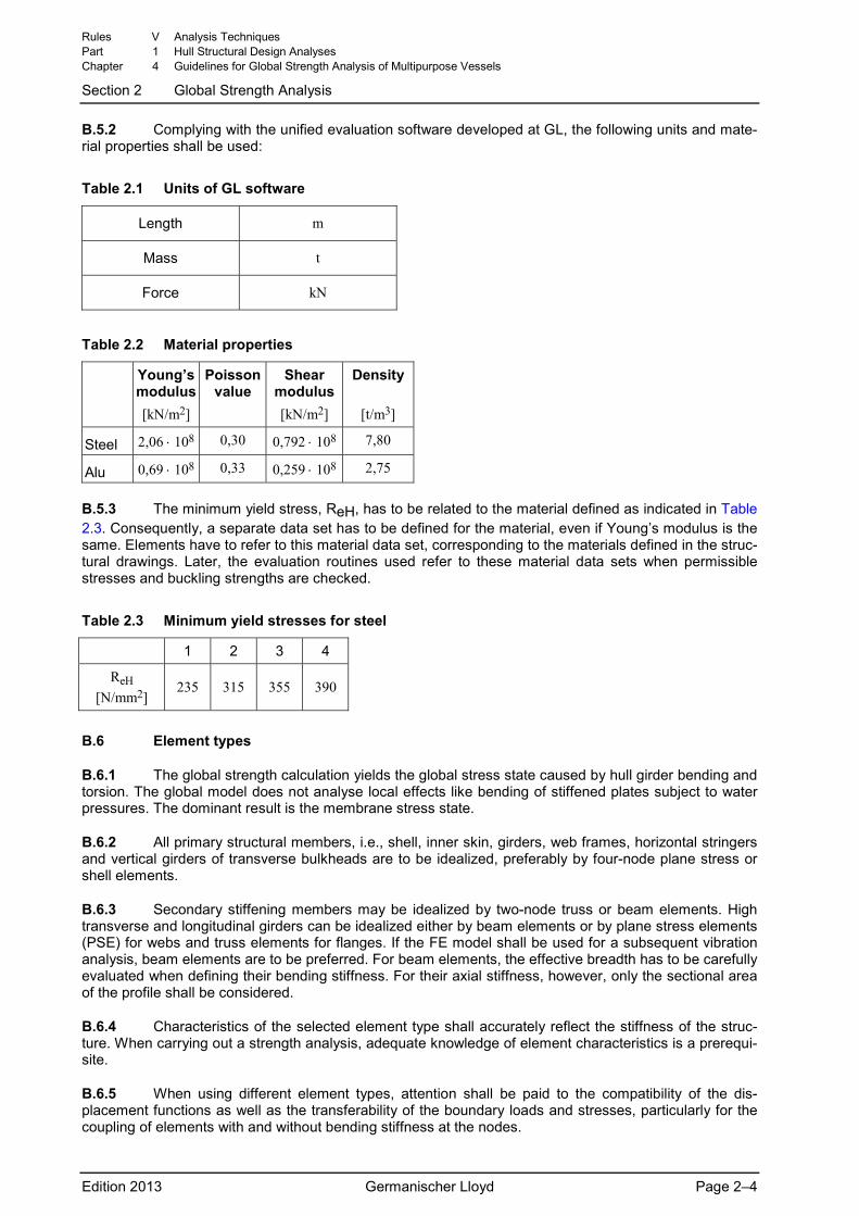
B.5.2 Complying with the unified evaluation software developed at GL, the following units and mate-rial properties shall be used:
Table 2.1 Units of GL software
Length m
Mass t
Force kN
Table 2.2 Material properties
Young’s modulus [kN/m2]
Poissonvalue
Shear modulus [kN/m2]
Density
[t/m3]
Steel 2,06 ⋅ 108 0,30 0,792 ⋅ 108 7,80
Alu 0,69 ⋅ 108 0,33 0,259 ⋅ 108 2,75
B.5.3 The minimum yield stress, ReH, has to be related to the material defined as indicated in Table 2.3. Consequently, a separate data set has to be defined for the material, even if Young’s modulus is the same. Elements have to refer to this material data set, corresponding to the materials defined in the struc-tural drawings. Later, the evaluation routines used refer to these material data sets when permissible stresses and buckling strengths are checked.
Table 2.3 Minimum yield stresses for steel
1 2 3 4
ReH [N/mm2]
235 315 355 390
B.6 Element types
B.6.1 The global strength calculation yields the global stress state caused by hull girder bending and torsion. The global model does not analyse local effects like bending of stiffened plates subject to water pressures. The dominant result is the membrane stress state.
B.6.2 All primary structural members, i.e., shell, inner skin, girders, web frames, horizontal stringers and vertical girders of transverse bulkheads are to be idealized, preferably by four-node plane stress or shell elements.
B.6.3 Secondary stiffening members may be idealized by two-node truss or beam elements. High transverse and longitudinal girders can be idealized either by beam elements or by plane stress elements (PSE) for webs and truss elements for flanges. If the FE model shall be used for a subsequent vibration analysis, beam elements are to be preferred. For beam elements, the effective breadth has to be carefully evaluated when defining their bending stiffness. For their axial stiffness, however, only the sectional area of the profile shall be considered.
B.6.4 Characteristics of the selected element type shall accurately reflect the stiffness of the struc-ture. When carrying out a strength analysis, adequate knowledge of element characteristics is a prerequi-site.
B.6.5 When using different element types, attention shall be paid to the compatibility of the dis-placement functions as well as the transferability of the boundary loads and stresses, particularly for the coupling of elements with and without bending stiffness at the nodes.
Rules V Analysis Techniques Part 1 Hull Structural Design Analyses Chapter 4 Guidelines for Global Strength Analysis of Multipurpose Vessels
Section 2 Global Strength Analysis
Edition 2013 Germanischer Lloyd Page 2–4
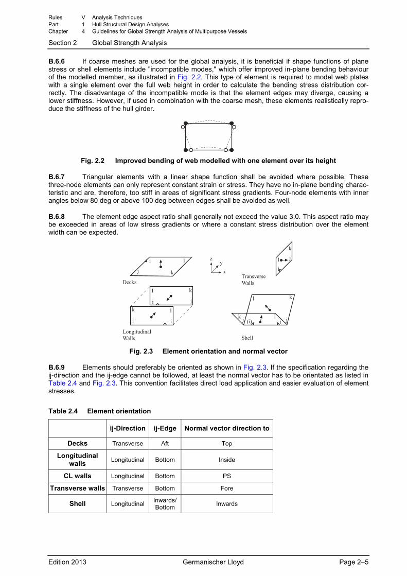
B.6.6 If coarse meshes are used for the global analysis, it is beneficial if shape functions of plane stress or shell elements include "incompatible modes," which offer improved in-plane bending behaviour of the modelled member, as illustrated in Fig. 2.2. This type of element is required to model web plates with a single element over the full web height in order to calculate the bending stress distribution cor-rectly. The disadvantage of the incompatible mode is that the element edges may diverge, causing a lower stiffness. However, if used in combination with the coarse mesh, these elements realistically repro-duce the stiffness of the hull girder.
Fig. 2.2 Improved bending of web modelled with one element over its height
B.6.7 Triangular elements with a linear shape function shall be avoided where possible. These three-node elements can only represent constant strain or stress. They have no in-plane bending charac-teristic and are, therefore, too stiff in areas of significant stress gradients. Four-node elements with inner angles below 80 deg or above 100 deg between edges shall be avoided as well.
B.6.8 The element edge aspect ratio shall generally not exceed the value 3.0. This aspect ratio may be exceeded in areas of low stress gradients or where a constant stress distribution over the element width can be expected.
� �
� �� �����
�
�
�
�
�
��
�
�
�
�
�
�
��
�
�
�� �������� ���
��������������� �� ���
�����
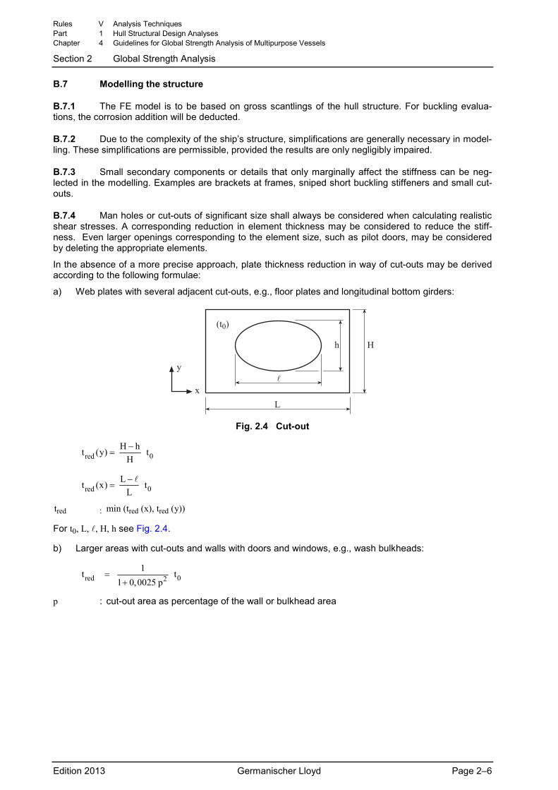
Fig. 2.3 Element orientation and normal vector
B.6.9 Elements should preferably be oriented as shown in Fig. 2.3. If the specification regarding the ij-direction and the ij-edge cannot be followed, at least the normal vector has to be orientated as listed in Table 2.4 and Fig. 2.3. This convention facilitates direct load application and easier evaluation of element stresses.
Table 2.4 Element orientation
ij-Direction ij-Edge Normal vector direction to
Decks Transverse Aft Top
Longitudinal walls Longitudinal Bottom Inside
CL walls Longitudinal Bottom PS
Transverse walls Transverse Bottom Fore
Shell Longitudinal Inwards/Bottom Inwards
Rules V Analysis Techniques Part 1 Hull Structural Design Analyses Chapter 4 Guidelines for Global Strength Analysis of Multipurpose Vessels
Section 2 Global Strength Analysis
Edition 2013 Germanischer Lloyd Page 2–5
B.7 Modelling the structure
B.7.1 The FE model is to be based on gross scantlings of the hull structure. For buckling evalua-tions, the corrosion addition will be deducted.
B.7.2 Due to the complexity of the ship’s structure, simplifications are generally necessary in model-ling. These simplifications are permissible, provided the results are only negligibly impaired.
B.7.3 Small secondary components or details that only marginally affect the stiffness can be neg-lected in the modelling. Examples are brackets at frames, sniped short buckling stiffeners and small cut-outs.
B.7.4 Man holes or cut-outs of significant size shall always be considered when calculating realistic shear stresses. A corresponding reduction in element thickness may be considered to reduce the stiff-ness. Even larger openings corresponding to the element size, such as pilot doors, may be considered by deleting the appropriate elements.
In the absence of a more precise approach, plate thickness reduction in way of cut-outs may be derived according to the following formulae:
a) Web plates with several adjacent cut-outs, e.g., floor plates and longitudinal bottom girders:
����
� �
�
�
Fig. 2.4 Cut-out
0redH ht (y) t
H−
=
0redLt (x) t
L−
=
tred : min (tred (x), tred (y))
For t0, L, , H, h see Fig. 2.4.
b) Larger areas with cut-outs and walls with doors and windows, e.g., wash bulkheads:
0red 21t t
1 0,0025 p=
+
p : cut-out area as percentage of the wall or bulkhead area
Rules V Analysis Techniques Part 1 Hull Structural Design Analyses Chapter 4 Guidelines for Global Strength Analysis of Multipurpose Vessels
Section 2 Global Strength Analysis
Edition 2013 Germanischer Lloyd Page 2–6
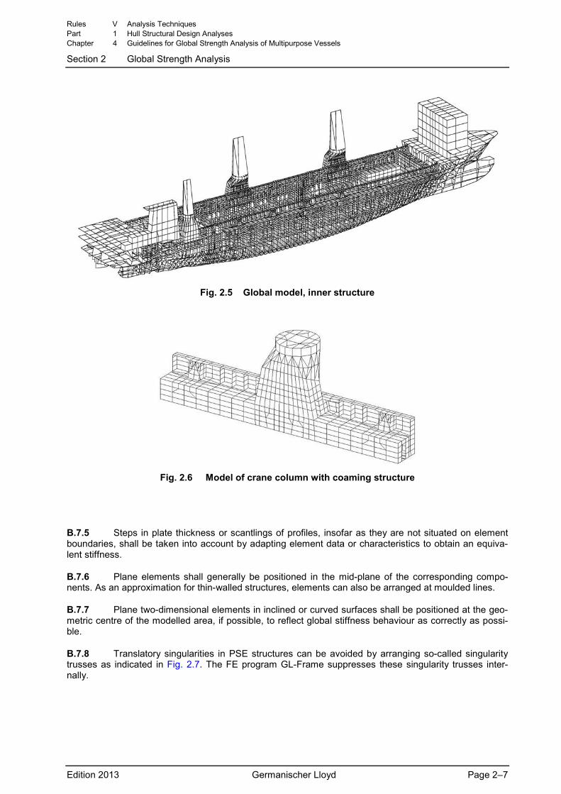
Fig. 2.5 Global model, inner structure
Fig. 2.6 Model of crane column with coaming structure
B.7.5 Steps in plate thickness or scantlings of profiles, insofar as they are not situated on element boundaries, shall be taken into account by adapting element data or characteristics to obtain an equiva-lent stiffness.
B.7.6 Plane elements shall generally be positioned in the mid-plane of the corresponding compo-nents. As an approximation for thin-walled structures, elements can also be arranged at moulded lines.
B.7.7 Plane two-dimensional elements in inclined or curved surfaces shall be positioned at the geo-metric centre of the modelled area, if possible, to reflect global stiffness behaviour as correctly as possi-ble.
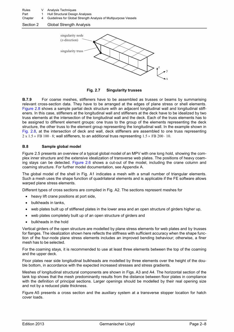
B.7.8 Translatory singularities in PSE structures can be avoided by arranging so-called singularity trusses as indicated in Fig. 2.7. The FE program GL-Frame suppresses these singularity trusses inter-nally.
Rules V Analysis Techniques Part 1 Hull Structural Design Analyses Chapter 4 Guidelines for Global Strength Analysis of Multipurpose Vessels
Section 2 Global Strength Analysis
Edition 2013 Germanischer Lloyd Page 2–7
������ ���������� ����������
�
������ ���������
Fig. 2.7 Singularity trusses
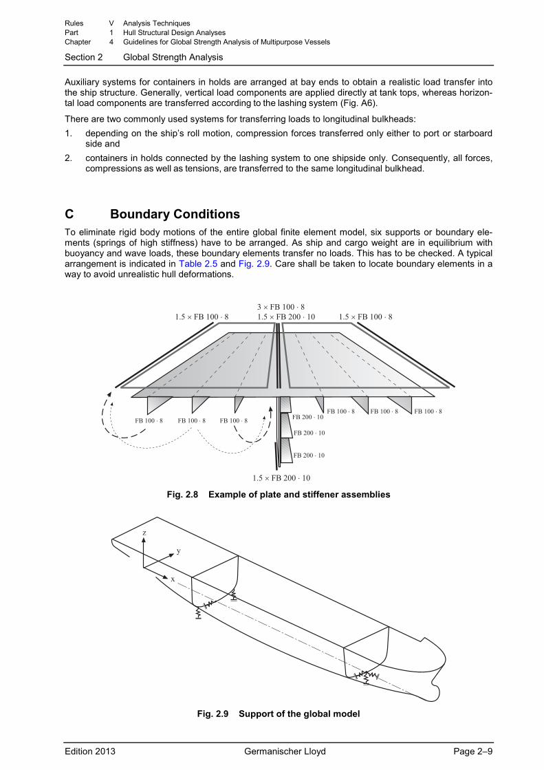
B.7.9 For coarse meshes, stiffeners have to be assembled as trusses or beams by summarising relevant cross-section data. They have to be arranged at the edges of plane stress or shell elements. Figure 2.8 shows a sample partial deck structure with an adjacent longitudinal wall and longitudinal stiff-eners. In this case, stiffeners at the longitudinal wall and stiffeners at the deck have to be idealized by two truss elements at the intersection of the longitudinal wall and the deck. Each of the truss elements has to be assigned to different element groups: one truss to the group of the elements representing the deck structure, the other truss to the element group representing the longitudinal wall. In the example shown in Fig. 2.8, at the intersection of deck and wall, deck stiffeners are assembled to one truss representing 2 x 1.5 × FB 100 ⋅ 8; wall stiffeners, to an additional truss representing 1.5 × FB 200 ⋅ 10.
B.8 Sample global model
Figure 2.5 presents an overview of a typical global model of an MPV with one long hold, showing the com-plex inner structure and the extensive idealization of transverse web plates. The positions of heavy coam-ing stays can be detected. Figure 2.6 shows a cut-out of the model, including the crane column and coaming structure. For further model documentation, see Appendix A.
The global model of the shell in Fig. A1 indicates a mesh with a small number of triangular elements. Such a mesh uses the shape function of quadrilateral elements and is applicable if the FE software allows warped plane stress elements.
Different types of cross sections are compiled in Fig. A2. The sections represent meshes for • heavy lift crane positions at port side, • bulkheads in tanks, • web plates built up of stiffened plates in the lower area and an open structure of girders higher up, • web plates completely built up of an open structure of girders and • bulkheads in the hold
Vertical girders of the open structure are modelled by plane stress elements for web plates and by trusses for flanges. The idealization shown here reflects the stiffness with sufficient accuracy when the shape func-tion of the four-node plane stress elements includes an improved bending behaviour; otherwise, a finer mesh has to be selected.
For the coaming stays, it is recommended to use at least three elements between the top of the coaming and the upper deck.
Floor plates near side longitudinal bulkheads are modelled by three elements over the height of the dou-ble bottom, in accordance with the expected increased stresses and stress gradients.
Meshes of longitudinal structural components are shown in Figs. A3 and A4. The horizontal section of the tank top shows that the mesh predominantly results from the distance between floor plates in compliance with the definition of principal sections. Larger openings should be modelled by their real opening size and not by a reduced plate thickness.
Figure A5 presents a cross section and the auxiliary system at a transverse stopper location for hatch cover loads.
Rules V Analysis Techniques Part 1 Hull Structural Design Analyses Chapter 4 Guidelines for Global Strength Analysis of Multipurpose Vessels
Section 2 Global Strength Analysis
Edition 2013 Germanischer Lloyd Page 2–8
Auxiliary systems for containers in holds are arranged at bay ends to obtain a realistic load transfer into the ship structure. Generally, vertical load components are applied directly at tank tops, whereas horizon-tal load components are transferred according to the lashing system (Fig. A6).
There are two commonly used systems for transferring loads to longitudinal bulkheads: 1. depending on the ship’s roll motion, compression forces transferred only either to port or starboard
side and 2. containers in holds connected by the lashing system to one shipside only. Consequently, all forces,
compressions as well as tensions, are transferred to the same longitudinal bulkhead.
C Boundary Conditions To eliminate rigid body motions of the entire global finite element model, six supports or boundary ele-ments (springs of high stiffness) have to be arranged. As ship and cargo weight are in equilibrium with buoyancy and wave loads, these boundary elements transfer no loads. This has to be checked. A typical arrangement is indicated in Table 2.5 and Fig. 2.9. Care shall be taken to locate boundary elements in a way to avoid unrealistic hull deformations.
!"#���$%�&�����!�
$%�&�����!�
$%�&�����!�
$%�&�����!�$%�!�����' $%�!�����' $%�!�����'
$%�!�����'$%�!�����'$%�!�����'
!"#���$%�!�����' !"#���$%�&�����!� !"#���$%�!�����'(���$%�!�����'
Fig. 2.8 Example of plate and stiffener assemblies
�
Fig. 2.9 Support of the global model
Rules V Analysis Techniques Part 1 Hull Structural Design Analyses Chapter 4 Guidelines for Global Strength Analysis of Multipurpose Vessels
Section 2 Global Strength Analysis
Edition 2013 Germanischer Lloyd Page 2–9
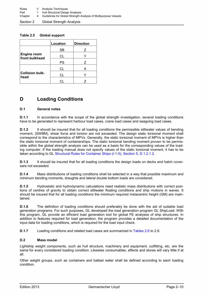
Table 2.5 Global support
Location Direction
SB Z
CL Y Engine room front bulkhead
PS Z
CL X
CL Y Collision bulk-head
CL Z
D Loading Conditions
D.1 General notes
D.1.1 In accordance with the scope of the global strength investigation, several loading conditions have to be generated to represent harbour load cases, crane load cases and seagoing load cases.
D.1.2 It should be insured that for all loading conditions the permissible stillwater values of bending moment, (SWBM), shear force and torsion are not exceeded. The design static torsional moment shall correspond to the characteristics of MPVs. Generally, the static torsional moment of MPVs is higher than the static torsional moment of containerships. The static torsional bending moment proven to be permis-sible within the global strength analysis can be used as a basis for the corresponding values of the load-ing computer. If the loading manual does not specify values of the static torsional moment, it has to be taken according to GL Structural Rules for Container Ships (I-1-5), Section 5, D.1.2.1.2.
D.1.3 It should be insured that for all loading conditions the design loads on decks and hatch cover-sare not exceeded.
D.1.4 Mass distributions of loading conditions shall be selected in a way that possible maximum and minimum bending moments, draughts and lateral double bottom loads are considered.
D.1.5 Hydrostatic and hydrodynamic calculations need realistic mass distributions with correct posi-tions of centres of gravity to obtain correct stillwater floating conditions and ship motions in waves. It should be insured that for all loading conditions the minimum required metacentric height (GM) are main-tained.
D.1.6 The definition of loading conditions should preferably be done with the aid of suitable load generation programs. For such purposes, GL developed the load generation program GL ShipLoad. With this program, GL provide an efficient load generation tool for global FE analyses of ship structures. In addition to features required for load generation, the program provides a detailed documentation of the input data for loading conditions, which is required for the load input check.
D.1.7 Loading conditions and related load cases are summarized in Tables 2.6 to 2.8.
D.2 Mass model
Lightship weight components, such as hull structure, machinery and equipment, outfitting, etc. are the same for every considered loading condition. Likewise consumables, effects and stores will vary little if at all.
Other weight groups, such as containers and ballast water shall be defined according to each loading condition.
Rules V Analysis Techniques Part 1 Hull Structural Design Analyses Chapter 4 Guidelines for Global Strength Analysis of Multipurpose Vessels
Section 2 Global Strength Analysis
Edition 2013 Germanischer Lloyd Page 2–10
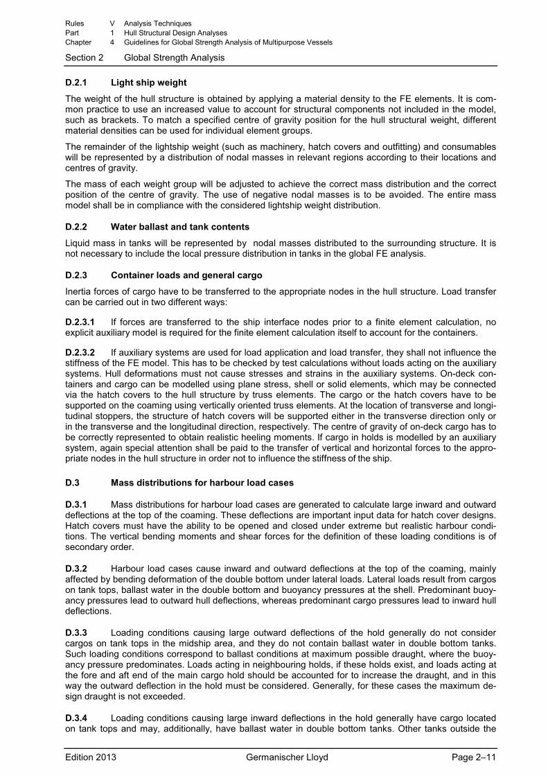
D.2.1 Light ship weight
The weight of the hull structure is obtained by applying a material density to the FE elements. It is com-mon practice to use an increased value to account for structural components not included in the model, such as brackets. To match a specified centre of gravity position for the hull structural weight, different material densities can be used for individual element groups.
The remainder of the lightship weight (such as machinery, hatch covers and outfitting) and consumables will be represented by a distribution of nodal masses in relevant regions according to their locations and centres of gravity.
The mass of each weight group will be adjusted to achieve the correct mass distribution and the correct position of the centre of gravity. The use of negative nodal masses is to be avoided. The entire mass model shall be in compliance with the considered lightship weight distribution.
D.2.2 Water ballast and tank contents
Liquid mass in tanks will be represented by nodal masses distributed to the surrounding structure. It is not necessary to include the local pressure distribution in tanks in the global FE analysis.
D.2.3 Container loads and general cargo
Inertia forces of cargo have to be transferred to the appropriate nodes in the hull structure. Load transfer can be carried out in two different ways:
D.2.3.1 If forces are transferred to the ship interface nodes prior to a finite element calculation, no explicit auxiliary model is required for the finite element calculation itself to account for the containers.
D.2.3.2 If auxiliary systems are used for load application and load transfer, they shall not influence the stiffness of the FE model. This has to be checked by test calculations without loads acting on the auxiliary systems. Hull deformations must not cause stresses and strains in the auxiliary systems. On-deck con-tainers and cargo can be modelled using plane stress, shell or solid elements, which may be connected via the hatch covers to the hull structure by truss elements. The cargo or the hatch covers have to be supported on the coaming using vertically oriented truss elements. At the location of transverse and longi-tudinal stoppers, the structure of hatch covers will be supported either in the transverse direction only or in the transverse and the longitudinal direction, respectively. The centre of gravity of on-deck cargo has to be correctly represented to obtain realistic heeling moments. If cargo in holds is modelled by an auxiliary system, again special attention shall be paid to the transfer of vertical and horizontal forces to the appro-priate nodes in the hull structure in order not to influence the stiffness of the ship.
D.3 Mass distributions for harbour load cases
D.3.1 Mass distributions for harbour load cases are generated to calculate large inward and outward deflections at the top of the coaming. These deflections are important input data for hatch cover designs. Hatch covers must have the ability to be opened and closed under extreme but realistic harbour condi-tions. The vertical bending moments and shear forces for the definition of these loading conditions is of secondary order.
D.3.2 Harbour load cases cause inward and outward deflections at the top of the coaming, mainly affected by bending deformation of the double bottom under lateral loads. Lateral loads result from cargos on tank tops, ballast water in the double bottom and buoyancy pressures at the shell. Predominant buoy-ancy pressures lead to outward hull deflections, whereas predominant cargo pressures lead to inward hull deflections.
D.3.3 Loading conditions causing large outward deflections of the hold generally do not consider cargos on tank tops in the midship area, and they do not contain ballast water in double bottom tanks. Such loading conditions correspond to ballast conditions at maximum possible draught, where the buoy-ancy pressure predominates. Loads acting in neighbouring holds, if these holds exist, and loads acting at the fore and aft end of the main cargo hold should be accounted for to increase the draught, and in this way the outward deflection in the hold must be considered. Generally, for these cases the maximum de-sign draught is not exceeded.
D.3.4 Loading conditions causing large inward deflections in the hold generally have cargo located on tank tops and may, additionally, have ballast water in double bottom tanks. Other tanks outside the
Rules V Analysis Techniques Part 1 Hull Structural Design Analyses Chapter 4 Guidelines for Global Strength Analysis of Multipurpose Vessels
Section 2 Global Strength Analysis
Edition 2013 Germanischer Lloyd Page 2–11
hold area should be empty if this is reasonable. To obtain maximum cargo pressure on a tank top, the load is concentrated in the middle of the main cargo hold. Neighbouring holds should be free of cargo. Generally, the maximum scantling draught is reached in these cases. Block load cases are typical loading conditions causing extreme inward deflections.
D.3.5 Generally, up to four harbour loading conditions are generated.
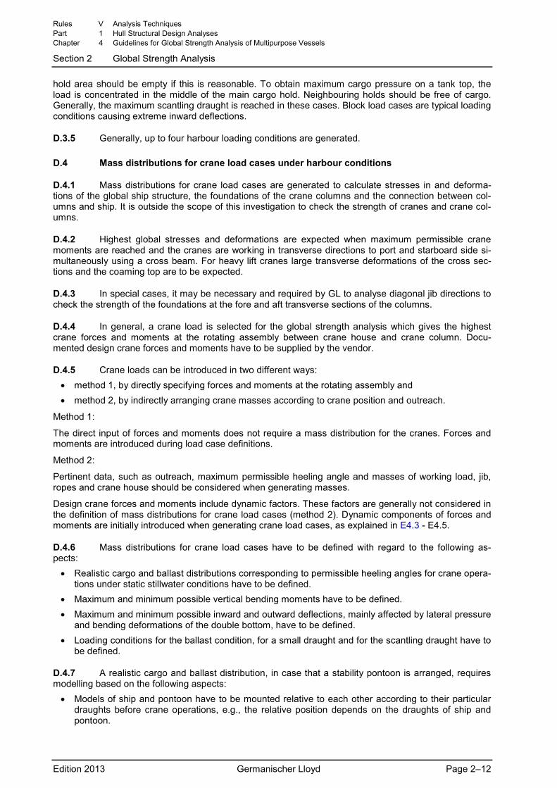
D.4 Mass distributions for crane load cases under harbour conditions
D.4.1 Mass distributions for crane load cases are generated to calculate stresses in and deforma-tions of the global ship structure, the foundations of the crane columns and the connection between col-umns and ship. It is outside the scope of this investigation to check the strength of cranes and crane col-umns.
D.4.2 Highest global stresses and deformations are expected when maximum permissible crane moments are reached and the cranes are working in transverse directions to port and starboard side si-multaneously using a cross beam. For heavy lift cranes large transverse deformations of the cross sec-tions and the coaming top are to be expected.
D.4.3 In special cases, it may be necessary and required by GL to analyse diagonal jib directions to check the strength of the foundations at the fore and aft transverse sections of the columns.
D.4.4 In general, a crane load is selected for the global strength analysis which gives the highest crane forces and moments at the rotating assembly between crane house and crane column. Docu-mented design crane forces and moments have to be supplied by the vendor.
D.4.5 Crane loads can be introduced in two different ways: • method 1, by directly specifying forces and moments at the rotating assembly and • method 2, by indirectly arranging crane masses according to crane position and outreach.
Method 1:
The direct input of forces and moments does not require a mass distribution for the cranes. Forces and moments are introduced during load case definitions.
Method 2:
Pertinent data, such as outreach, maximum permissible heeling angle and masses of working load, jib, ropes and crane house should be considered when generating masses.
Design crane forces and moments include dynamic factors. These factors are generally not considered in the definition of mass distributions for crane load cases (method 2). Dynamic components of forces and moments are initially introduced when generating crane load cases, as explained in E4.3 - E4.5.
D.4.6 Mass distributions for crane load cases have to be defined with regard to the following as-pects:
• Realistic cargo and ballast distributions corresponding to permissible heeling angles for crane opera-tions under static stillwater conditions have to be defined.
• Maximum and minimum possible vertical bending moments have to be defined. • Maximum and minimum possible inward and outward deflections, mainly affected by lateral pressure
and bending deformations of the double bottom, have to be defined. • Loading conditions for the ballast condition, for a small draught and for the scantling draught have to
be defined.
D.4.7 A realistic cargo and ballast distribution, in case that a stability pontoon is arranged, requires modelling based on the following aspects:
• Models of ship and pontoon have to be mounted relative to each other according to their particular draughts before crane operations, e.g., the relative position depends on the draughts of ship and pontoon.
Rules V Analysis Techniques Part 1 Hull Structural Design Analyses Chapter 4 Guidelines for Global Strength Analysis of Multipurpose Vessels
Section 2 Global Strength Analysis
Edition 2013 Germanischer Lloyd Page 2–12
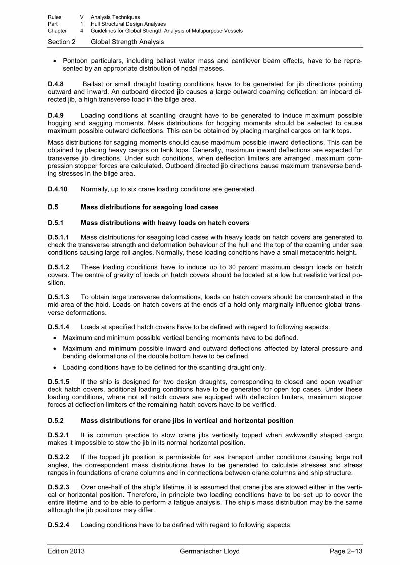
• Pontoon particulars, including ballast water mass and cantilever beam effects, have to be repre-sented by an appropriate distribution of nodal masses.
D.4.8 Ballast or small draught loading conditions have to be generated for jib directions pointing outward and inward. An outboard directed jib causes a large outward coaming deflection; an inboard di-rected jib, a high transverse load in the bilge area.
D.4.9 Loading conditions at scantling draught have to be generated to induce maximum possible hogging and sagging moments. Mass distributions for hogging moments should be selected to cause maximum possible outward deflections. This can be obtained by placing marginal cargos on tank tops.
Mass distributions for sagging moments should cause maximum possible inward deflections. This can be obtained by placing heavy cargos on tank tops. Generally, maximum inward deflections are expected for transverse jib directions. Under such conditions, when deflection limiters are arranged, maximum com-pression stopper forces are calculated. Outboard directed jib directions cause maximum transverse bend-ing stresses in the bilge area.
D.4.10 Normally, up to six crane loading conditions are generated.
D.5 Mass distributions for seagoing load cases
D.5.1 Mass distributions with heavy loads on hatch covers
D.5.1.1 Mass distributions for seagoing load cases with heavy loads on hatch covers are generated to check the transverse strength and deformation behaviour of the hull and the top of the coaming under sea conditions causing large roll angles. Normally, these loading conditions have a small metacentric height.
D.5.1.2 These loading conditions have to induce up to 80 percent maximum design loads on hatch covers. The centre of gravity of loads on hatch covers should be located at a low but realistic vertical po-sition.
D.5.1.3 To obtain large transverse deformations, loads on hatch covers should be concentrated in the mid area of the hold. Loads on hatch covers at the ends of a hold only marginally influence global trans-verse deformations.
D.5.1.4 Loads at specified hatch covers have to be defined with regard to following aspects: • Maximum and minimum possible vertical bending moments have to be defined. • Maximum and minimum possible inward and outward deflections affected by lateral pressure and
bending deformations of the double bottom have to be defined. • Loading conditions have to be defined for the scantling draught only.
D.5.1.5 If the ship is designed for two design draughts, corresponding to closed and open weather deck hatch covers, additional loading conditions have to be generated for open top cases. Under these loading conditions, where not all hatch covers are equipped with deflection limiters, maximum stopper forces at deflection limiters of the remaining hatch covers have to be verified.
D.5.2 Mass distributions for crane jibs in vertical and horizontal position
D.5.2.1 It is common practice to stow crane jibs vertically topped when awkwardly shaped cargo makes it impossible to stow the jib in its normal horizontal position.
D.5.2.2 If the topped jib position is permissible for sea transport under conditions causing large roll angles, the correspondent mass distributions have to be generated to calculate stresses and stress ranges in foundations of crane columns and in connections between crane columns and ship structure.
D.5.2.3 Over one-half of the ship’s lifetime, it is assumed that crane jibs are stowed either in the verti-cal or horizontal position. Therefore, in principle two loading conditions have to be set up to cover the entire lifetime and to be able to perform a fatigue analysis. The ship’s mass distribution may be the same although the jib positions may differ.
D.5.2.4 Loading conditions have to be defined with regard to following aspects:
Rules V Analysis Techniques Part 1 Hull Structural Design Analyses Chapter 4 Guidelines for Global Strength Analysis of Multipurpose Vessels
Section 2 Global Strength Analysis
Edition 2013 Germanischer Lloyd Page 2–13
• Maximum displacement at scantling draught with maximum permissible vertical hogging stillwater bending moment causing a homogeneous weight distribution in holds and on hatch covers has to be maintained.
• As horizontal accelerations of jibs under seagoing conditions are of major importance, a high but re-alistic metacentric height (GM) should be considered.
D.5.3 Mass distributions for container load cases
D.5.3.1 On special demand by GL, an investigation under conventional container loading conditions is required only for large MPVs.
D.5.3.2 In general, at least one hogging loading condition has to be generated. It has to be defined with regard to the following aspects:
• Maximum displacement at scantling draught with maximum permissible vertical hogging still water bending moment has to be generated.
• A homogeneous weight distribution in all bays with large stack loads on deck and hatch covers has to be generated.
• A relatively small metacentric height (GM) has to be considered.
D.5.4 Mass distributions for block load cases
D.5.4.1 Special mass distributions with block loads defined in the loading manual have to be investi-gated if applicable. For these cases, high cargo pressures at tank tops are transferred into the bottom structure.
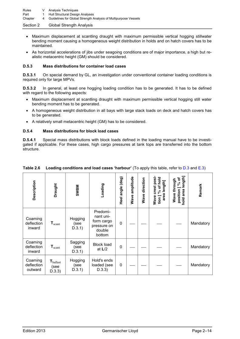
Table 2.6 Loading conditions and load cases ‘harbour’ (To apply this table, refer to D.3 and E.3)
Des
crip
tion
Dra
ught
SWB
M
Load
ing
Hee
l ang
le (d
eg)
Wav
e am
plitu
de
Wav
e di
rect
ion
Wav
e cr
est p
osi-
tion
[ % o
f hol
d ar
ea le
ngth
]
Wav
e th
roug
h po
sitio
n [ %
of
hold
are
a le
ngth
]
Rem
ark
Coaming deflection
inward Tscant
Hogging (see
D.3.1)
Predomi-nant uni-
form cargo pressure on
double bottom
0 ⎯ ⎯ ⎯ ⎯ Mandatory
Coaming deflection
inward Tscant
Sagging (see
D.3.1)
Block load at L/2 0 ⎯ ⎯ ⎯ ⎯ Mandatory
Coaming deflection outward
Tballast (see
D.3.3)
Hogging (see
D.3.1)
Hold's ends loaded (see
D.3.3) 0 ⎯ ⎯ ⎯ ⎯ Mandatory
Rules V Analysis Techniques Part 1 Hull Structural Design Analyses Chapter 4 Guidelines for Global Strength Analysis of Multipurpose Vessels
Section 2 Global Strength Analysis
Edition 2013 Germanischer Lloyd Page 2–14
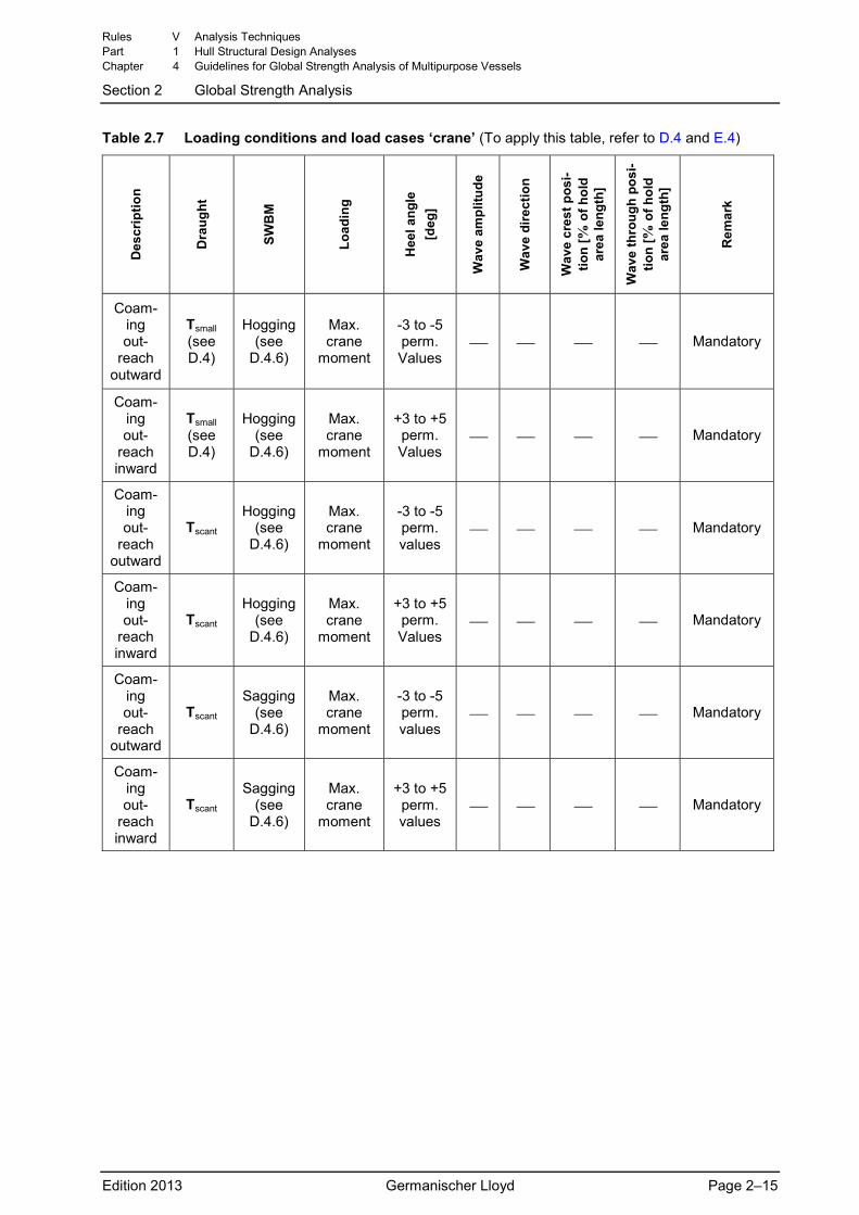
Table 2.7 Loading conditions and load cases ‘crane’ (To apply this table, refer to D.4 and E.4) D
escr
iptio
n
Dra
ught
SWB
M
Load
ing
Hee
l ang
le
[deg
]
Wav
e am
plitu
de
Wav
e di
rect
ion
Wav
e cr
est p
osi-
tion
[% o
f hol
d ar
ea le
ngth
]
Wav
e th
roug
h po
si-
tion
[% o
f hol
d ar
ea le
ngth
]
Rem
ark
Coam-ing out-
reach outward
Tsmall (see D.4)
Hogging (see
D.4.6)
Max. crane
moment
-3 to -5 perm. Values
⎯ ⎯ ⎯ ⎯ Mandatory
Coam-ing out-
reach inward
Tsmall (see D.4)
Hogging (see
D.4.6)
Max. crane
moment
+3 to +5 perm. Values
⎯ ⎯ ⎯ ⎯ Mandatory
Coam-ing out-
reach outward
Tscant Hogging
(see D.4.6)
Max. crane
moment
-3 to -5 perm. values
⎯ ⎯ ⎯ ⎯ Mandatory
Coam-ing out-
reach inward
Tscant Hogging
(see D.4.6)
Max. crane
moment
+3 to +5 perm. Values
⎯ ⎯ ⎯ ⎯ Mandatory
Coam-ing out-
reach outward
Tscant Sagging
(see D.4.6)
Max. crane
moment
-3 to -5 perm. values
⎯ ⎯ ⎯ ⎯ Mandatory
Coam-ing out-
reach inward
Tscant Sagging
(see D.4.6)
Max. crane
moment
+3 to +5 perm. values
⎯ ⎯ ⎯ ⎯ Mandatory
Rules V Analysis Techniques Part 1 Hull Structural Design Analyses Chapter 4 Guidelines for Global Strength Analysis of Multipurpose Vessels
Section 2 Global Strength Analysis
Edition 2013 Germanischer Lloyd Page 2–15
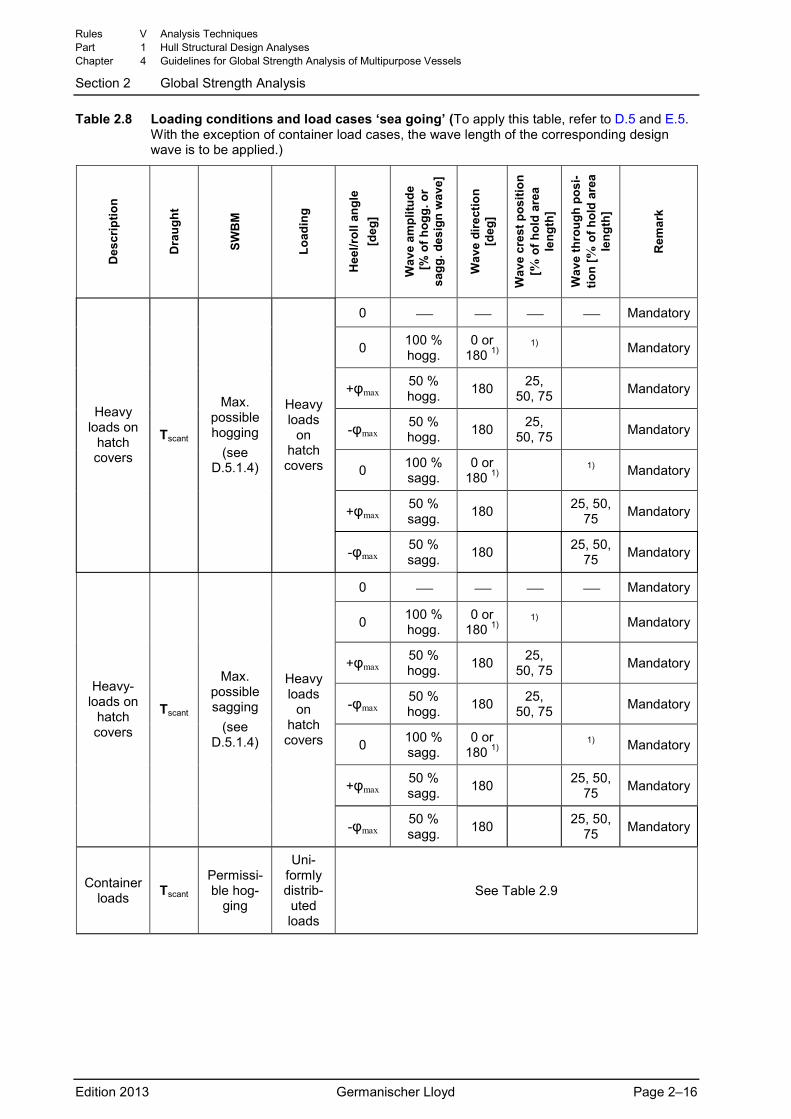
Table 2.8 Loading conditions and load cases ‘sea going’ (To apply this table, refer to D.5 and E.5. With the exception of container load cases, the wave length of the corresponding design wave is to be applied.)
Des
crip
tion
Dra
ught
SWB
M
Load
ing
Hee
l/rol
l ang
le
[deg
]
Wav
e am
plitu
de
[% o
f hog
g. o
r sa
gg. d
esig
n w
ave]
Wav
e di
rect
ion
[deg
]
Wav
e cr
est p
ositi
on
[% o
f hol
d ar
ea
leng
th]
Wav
e th
roug
h po
si-
tion
[ % o
f hol
d ar
ea
leng
th]
Rem
ark
0 ⎯ ⎯ ⎯ ⎯ Mandatory
0 100 % hogg.
0 or 180 1)
1) Mandatory
+φmax 50 % hogg. 180 25,
50, 75 Mandatory
-φmax 50 % hogg. 180 25,
50, 75 Mandatory
0 100 % sagg.
0 or 180 1) 1) Mandatory
+φmax 50 % sagg. 180 25, 50,
75 Mandatory
Heavy loads on
hatch covers
Tscant
Max. possible hogging
(see D.5.1.4)
Heavy loads
on hatch covers
-φmax 50 % sagg. 180 25, 50,
75 Mandatory
0 ⎯ ⎯ ⎯ ⎯ Mandatory
0 100 % hogg.
0 or 180 1)
1) Mandatory
+φmax 50 % hogg. 180 25,
50, 75 Mandatory
-φmax 50 % hogg. 180 25,
50, 75 Mandatory
0 100 % sagg.
0 or 180 1) 1) Mandatory
+φmax 50 % sagg. 180 25, 50,
75 Mandatory
Heavy-loads on
hatch covers
Tscant
Max. possible sagging
(see D.5.1.4)
Heavy loads
on hatch covers
-φmax 50 % sagg. 180 25, 50,
75 Mandatory
Container loads Tscant
Permissi-ble hog-
ging
Uni-formly distrib-uted loads
See Table 2.9
Rules V Analysis Techniques Part 1 Hull Structural Design Analyses Chapter 4 Guidelines for Global Strength Analysis of Multipurpose Vessels
Section 2 Global Strength Analysis
Edition 2013 Germanischer Lloyd Page 2–16
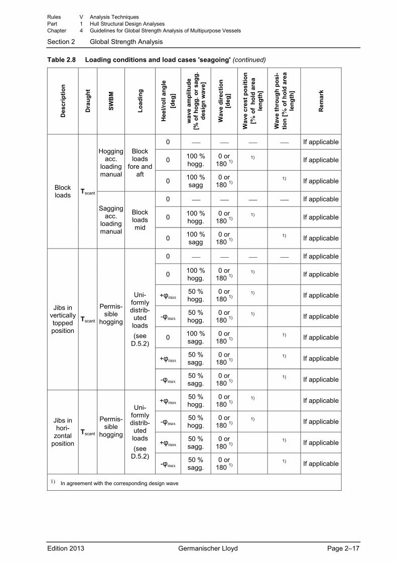
Table 2.8 Loading conditions and load cases 'seagoing' (continued) D
escr
iptio
n
Dra
ught
SWB
M
Load
ing
Hee
l/rol
l ang
le
[deg
]
wav
e am
plitu
de
[% o
f hog
g. o
r sag
g.
desi
gn w
ave]
Wav
e di
rect
ion
[d
eg]
Wav
e cr
est p
ositi
on
[% o
f ho
ld a
rea
leng
th]
Wav
e th
roug
h po
si-
tion
[ % o
f hol
d ar
ea
leng
th]
Rem
ark
0 ⎯ ⎯ ⎯ ⎯ If applicable
0 100 % hogg.
0 or 180 1)
1) If applicableHogging
acc. loading manual
Block loads
fore and aft
0 100 % sagg
0 or 180 1) 1) If applicable
0 ⎯ ⎯ ⎯ ⎯ If applicable
0 100 % hogg.
0 or 180 1)
1) If applicable
Block loads Tscant
Sagging acc.
loading manual
Block loads mid
0 100 % sagg
0 or 180 1) 1) If applicable
0 ⎯ ⎯ ⎯ ⎯ If applicable
0 100 % hogg.
0 or 180 1)
1) If applicable
+φmax 50 % hogg.
0 or 180 1)
1) If applicable
-φmax 50 % hogg.
0 or 180 1)
1) If applicable
0 100 % sagg.
0 or 180 1) 1) If applicable
+φmax 50 % sagg.
0 or 180 1) 1) If applicable
Jibs in vertically topped position
Tscant
Permis-sible
hogging
Uni-formly distrib-uted loads (see
D.5.2)
-φmax 50 % sagg.
0 or 180 1) 1) If applicable
+φmax 50 % hogg.
0 or 180 1)
1) If applicable
-φmax 50 % hogg.
0 or 180 1)
1) If applicable
+φmax 50 % sagg.
0 or 180 1) 1) If applicable
Jibs in hori-
zontal position
Tscant
Permis-sible
hogging
Uni-formly distrib-uted loads (see
D.5.2) -φmax
50 % sagg.
0 or 180 1) 1) If applicable
1) In agreement with the corresponding design wave
Rules V Analysis Techniques Part 1 Hull Structural Design Analyses Chapter 4 Guidelines for Global Strength Analysis of Multipurpose Vessels
Section 2 Global Strength Analysis
Edition 2013 Germanischer Lloyd Page 2–17
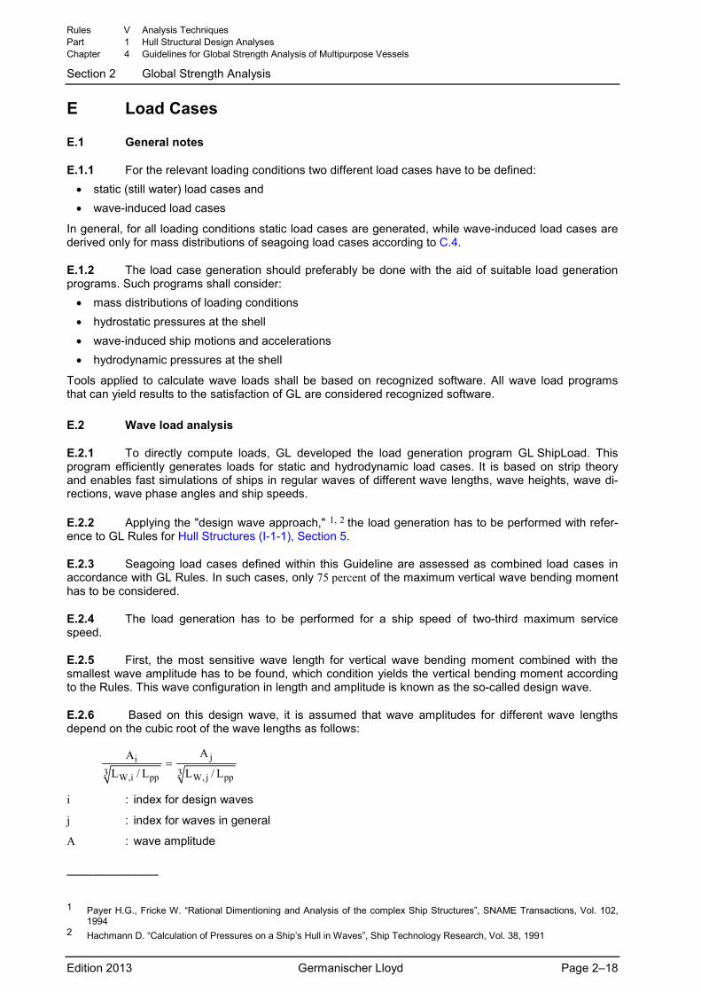
E Load Cases
E.1 General notes
E.1.1 For the relevant loading conditions two different load cases have to be defined: • static (still water) load cases and • wave-induced load cases
In general, for all loading conditions static load cases are generated, while wave-induced load cases are derived only for mass distributions of seagoing load cases according to C.4.
E.1.2 The load case generation should preferably be done with the aid of suitable load generation programs. Such programs shall consider:
• mass distributions of loading conditions • hydrostatic pressures at the shell • wave-induced ship motions and accelerations • hydrodynamic pressures at the shell
Tools applied to calculate wave loads shall be based on recognized software. All wave load programs that can yield results to the satisfaction of GL are considered recognized software.
E.2 Wave load analysis
E.2.1 To directly compute loads, GL developed the load generation program GL ShipLoad. This program efficiently generates loads for static and hydrodynamic load cases. It is based on strip theory and enables fast simulations of ships in regular waves of different wave lengths, wave heights, wave di-rections, wave phase angles and ship speeds.
E.2.2 Applying the "design wave approach," 1, 2 the load generation has to be performed with refer-ence to GL Rules for Hull Structures (I-1-1), Section 5.
E.2.3 Seagoing load cases defined within this Guideline are assessed as combined load cases in accordance with GL Rules. In such cases, only 75 percent of the maximum vertical wave bending moment has to be considered.
E.2.4 The load generation has to be performed for a ship speed of two-third maximum service speed.
E.2.5 First, the most sensitive wave length for vertical wave bending moment combined with the smallest wave amplitude has to be found, which condition yields the vertical bending moment according to the Rules. This wave configuration in length and amplitude is known as the so-called design wave.
E.2.6 Based on this design wave, it is assumed that wave amplitudes for different wave lengths depend on the cubic root of the wave lengths as follows:
ji3 3W,i pp W, j pp
AAL / L L / L
=
i : index for design waves
j : index for waves in general
A : wave amplitude
––––––––––––––
1 Payer H.G., Fricke W. “Rational Dimentioning and Analysis of the complex Ship Structures”, SNAME Transactions, Vol. 102,
1994 2 Hachmann D. “Calculation of Pressures on a Ship’s Hull in Waves”, Ship Technology Research, Vol. 38, 1991
Rules V Analysis Techniques Part 1 Hull Structural Design Analyses Chapter 4 Guidelines for Global Strength Analysis of Multipurpose Vessels
Section 2 Global Strength Analysis
Edition 2013 Germanischer Lloyd Page 2–18
LW : wave length
Lpp : ship length between perpendiculars
E.2.7 To obtain loads at large roll angles that comply with design roll angles and design transverse accelerations, respectively, GL ShipLoad makes it possible to consider additional roll angles. In this way it is possible to analyse specific rolling conditions in waves.
E.2.8 To avoid unrealistic load combinations, statistical independence between wave amplitude and additional roll angle shall be assumed, i.e., it is assumed that maximum wave amplitude and maximum roll angle do not occur simultaneously.
E.2.9 In general, for simulations in regular waves a large number of wave situations is systematically analysed by considering different wave lengths, wave heights, wave angles of encounter, wave phases (position of wave crest relative to the ship) and additional roll angles.
E.2.10 Relevant load cases for FE analyses generally are to be selected by evaluating sectional forces and moments along the ship’s length for all analysed wave situations. For these load cases, verti-cal and horizontal wave bending and the torsional moments have to match design values defined in the Rules. For MPVs the transverse acceleration of hatch cover loads is an additional essential item for the load case selection.
E.2.11 Selected seagoing load cases shall cover realistic combinations, consisting of vertical and horizontal moments, torsional moments, shear forces and large transverse forces leading to racking con-ditions.
E.2.12 Load case selection has to be done in a way to obtain the largest stress values and stress ranges relevant for fatigue.
E.3 Harbour load cases
E.3.1 Harbour load cases are summarized in Table 2.6.
E.3.2 Harbour load cases are assigned as static load cases. Target values are harbour stillwater forces and moments. Buoyancy pressures under stillwater conditions and inertia forces caused by gravi-tational acceleration result in a state of equilibrium.
E.4 Crane load cases
E.4.1 Crane load cases are summarized in Table 2.7.
E.4.2 Crane load cases are generally derived by superposition of a static and a dynamic part. The static part considers the mass distribution of the ship and crane without dynamic factors under stillwater floating conditions. Under this floating condition, the permissible heeling angle for crane operations shall be maintained. The dynamic part balances the dynamic crane forces and moments and the inertia forces of the ship’s masses.
E.4.3 If crane forces and moments acting at the rotating assembly are used directly (method 1), design forces and moments of cranes (including dynamic factors) and buoyancy forces for the stillwater floating condition are balanced by inertia forces of the ship’s masses. The buoyancy distribution shall fit the floating condition under static crane loads without considering dynamic effects.
E.4.4 If the considered crane masses are located at their correct centres of gravity (method 2), a stillwater floating condition is initially determined, which accounts for the static part of the crane forces and moments. The remaining dynamic forces and moments are then applied at the rotating crane assem-bly and balanced by inertia forces of the ship’s masses.
E.4.5 If a stability pontoon is used, it has to be considered for load case generation. The advantage of a stability pontoon is that it increases the moment of inertia of the water plane area and that it in-creases the metacentric height (GM), thus resulting in smaller heel and trim angles under crane load con-ditions.
Rules V Analysis Techniques Part 1 Hull Structural Design Analyses Chapter 4 Guidelines for Global Strength Analysis of Multipurpose Vessels
Section 2 Global Strength Analysis
Edition 2013 Germanischer Lloyd Page 2–19
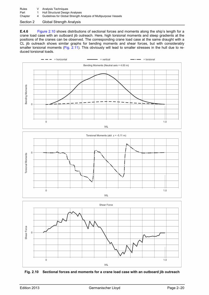
E.4.6 Figure 2.10 shows distributions of sectional forces and moments along the ship’s length for a crane load case with an outboard jib outreach. Here, high torsional moments and steep gradients at the positions of the cranes can be observed. The corresponding crane load case at the same draught with a CL jib outreach shows similar graphs for bending moments and shear forces, but with considerably smaller torsional moments (Fig. 2.11). This obviously will lead to smaller stresses in the hull due to re-duced torsional loads.
�
� ���
���
���� ������ �������� ���� � ���� ��
��
��
���
���
� ��������� � ����� �� � ��������
�
� ���
���
!������� ������ ��"� � � #$��� ��
!������
� ���
���
���
���
%���� &�� �
%��
�� &�� �
�
�
Fig. 2.10 Sectional forces and moments for a crane load case with an outboard jib outreach
Rules V Analysis Techniques Part 1 Hull Structural Design Analyses Chapter 4 Guidelines for Global Strength Analysis of Multipurpose Vessels
Section 2 Global Strength Analysis
Edition 2013 Germanischer Lloyd Page 2–20
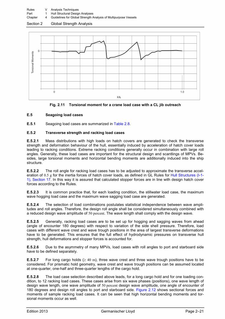
�
� ���
���
!������
� ���
���
Fig. 2.11 Torsional moment for a crane load case with a CL jib outreach
E.5 Seagoing load cases
E.5.1 Seagoing load cases are summarized in Table 2.8.
E.5.2 Transverse strength and racking load cases
E.5.2.1 Mass distributions with high loads on hatch covers are generated to check the transverse strength and deformation behaviour of the hull, essentially induced by acceleration of hatch cover loads leading to racking conditions. Extreme racking conditions generally occur in combination with large roll angles. Generally, these load cases are important for the structural design and scantlings of MPVs. Be-sides, large torsional moments and horizontal bending moments are additionally induced into the ship structure.
E.5.2.2 The roll angle for racking load cases has to be adjusted to approximate the transverse accel-eration of 0.5 g for the inertia forces of hatch cover loads, as defined in GL Rules for Hull Structures (I-1-1), Section 17. In this way it is assured that calculated stopper forces are in line with design hatch cover forces according to the Rules.
E.5.2.3 It is common practice that, for each loading condition, the stillwater load case, the maximum wave hogging load case and the maximum wave sagging load case are generated.
E.5.2.4 The selection of load combinations postulates statistical independence between wave ampli-tudes and roll angles. Therefore, the design roll angle shall be considered simultaneously combined with a reduced design wave amplitude of 50 percent. The wave length shall comply with the design wave.
E.5.2.5 Generally, racking load cases are to be set up for hogging and sagging waves from ahead (angle of encounter 180 degrees) with respect to variation of the side shell pressure. Therefore, load cases with different wave crest and wave trough positions in the area of largest transverse deformations have to be generated. This ensures that the full effect of hydrodynamic pressures on transverse hull strength, hull deformations and stopper forces is accounted for.
E.5.2.6 Due to the asymmetry of many MPVs, load cases with roll angles to port and starboard side have to be defined separately.
E.5.2.7 For long cargo holds (≥ 40 m), three wave crest and three wave trough positions have to be considered. For prismatic hold geometry, wave crest and wave trough positions can be assumed located at one-quarter, one-half and three-quarter lengths of the cargo hold.
E.5.2.8 The load case selection described above leads, for a long cargo hold and for one loading con-dition, to 12 racking load cases. These cases arise from six wave phases (positions), one wave length of design wave length, one wave amplitude of 50 percent design wave amplitude, one angle of encounter of 180 degrees and design roll angles to port and starboard side. Figure 2.12 shows sectional forces and moments of sample racking load cases. It can be seen that high horizontal bending moments and tor-sional moments occur as well.
Rules V Analysis Techniques Part 1 Hull Structural Design Analyses Chapter 4 Guidelines for Global Strength Analysis of Multipurpose Vessels
Section 2 Global Strength Analysis
Edition 2013 Germanischer Lloyd Page 2–21
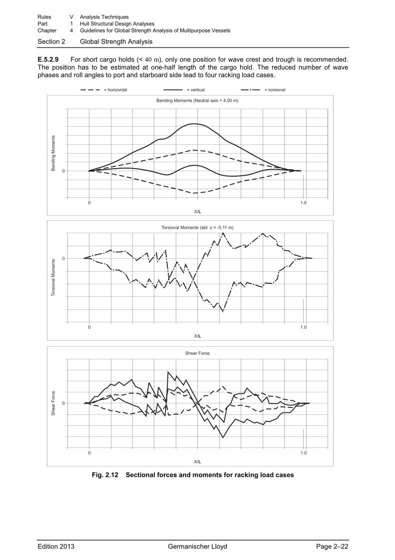
E.5.2.9 For short cargo holds (< 40 m), only one position for wave crest and trough is recommended. The position has to be estimated at one-half length of the cargo hold. The reduced number of wave phases and roll angles to port and starboard side lead to four racking load cases.
�
� ���
���
���� ������ �������� ���� � ���� ��
��
��
���
���
� ��������� � ����� �� � ��������
�
� ���
���
!������� ������ ��"� � � #$��� ��
!������
� ���
���
���
���
%���� &�� �
%��
�� &�� �
�
�
Fig. 2.12 Sectional forces and moments for racking load cases
Rules V Analysis Techniques Part 1 Hull Structural Design Analyses Chapter 4 Guidelines for Global Strength Analysis of Multipurpose Vessels
Section 2 Global Strength Analysis
Edition 2013 Germanischer Lloyd Page 2–22
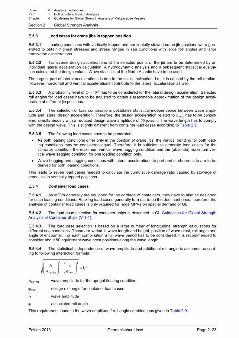
E.5.3 Load cases for crane jibs in topped position
E.5.3.1 Loading conditions with vertically topped and horizontally stowed crane jib positions were gen-erated to obtain highest stresses and stress ranges in sea conditions with large roll angles and large transverse accelerations.
E.5.3.2 Transverse design accelerations at the selected points of the jib are to be determined by an individual lateral acceleration calculation. A hydrodynamic analysis and a subsequent statistical evalua-tion calculated the design values. Wave statistics of the North Atlantic have to be used.
The largest part of lateral accelerations is due to the ship's inclination, i.e., it is caused by the roll motion. However, horizontal and vertical accelerations contribute to the lateral acceleration as well.
E.5.3.3 A probability level of Q = 10-6 has to be considered for the lateral design acceleration. Selected roll angles for load cases have to be adjusted to obtain a reasonable approximation of the design accel-eration at different jib positions.
E.5.3.4 The selection of load combinations postulates statistical independence between wave ampli-tude and lateral design acceleration. Therefore, the design acceleration related to ϕmax has to be consid-ered simultaneously with a reduced design wave amplitude of 50 percent. The wave length has to comply with the design wave. This is slightly different from container load cases according to Table 2.9.
E.5.3.5 The following load cases have to be generated: • As both loading conditions differ only in the position of crane jibs, the vertical bending for both load-
ing conditions may be considered equal. Therefore, it is sufficient to generate load cases for the stillwater condition, the maximum vertical wave hogging condition and the (absolute) maximum ver-tical wave sagging condition for one loading condition only.
• Wave hogging and sagging conditions with lateral accelerations to port and starboard side are to be derived for both loading conditions.
This leads to seven load cases needed to calculate the cumulative damage ratio caused by stowage of crane jibs in vertically topped positions.
E.5.4 Container load cases
E.5.4.1 As MPVs generally are equipped for the carriage of containers, they have to also be designed for such loading conditions. Racking load cases generally turn out to be the dominant ones; therefore, the analysis of container load cases is only required for large MPVs on special demand of GL.
E.5.4.2 The load case selection for container ships is described in GL Guidelines for Global Strength Analysis of Container Ships (V-1-1).
E.5.4.3 The load case selection is based on a large number of longitudinal strength calculations for different sea conditions. These are varied in wave length and height, position of wave crest, roll angle and angle of encounter. For each combination a full wave period has to be considered. It is recommended to consider about 50 equidistant wave crest positions along the wave length
E.5.4.4 The statistical independence of wave amplitude and additional roll angle is assumed, accord-ing to following interaction formula:
( )
2 2
max0
A 1,0A ϕ=
⎛ ⎞ ⎛ ⎞ϕ⎜ ⎟ + =⎜ ⎟⎜ ⎟ ϕ⎝ ⎠⎝ ⎠
A(ϕ=0) : wave amplitude for the upright floating condition
ϕmax : design roll angle for container load cases
A : wave amplitude
ϕ : associated roll angle
This requirement leads to the wave amplitude / roll angle combinations given in Table 2.9.
Rules V Analysis Techniques Part 1 Hull Structural Design Analyses Chapter 4 Guidelines for Global Strength Analysis of Multipurpose Vessels
Section 2 Global Strength Analysis
Edition 2013 Germanischer Lloyd Page 2–23
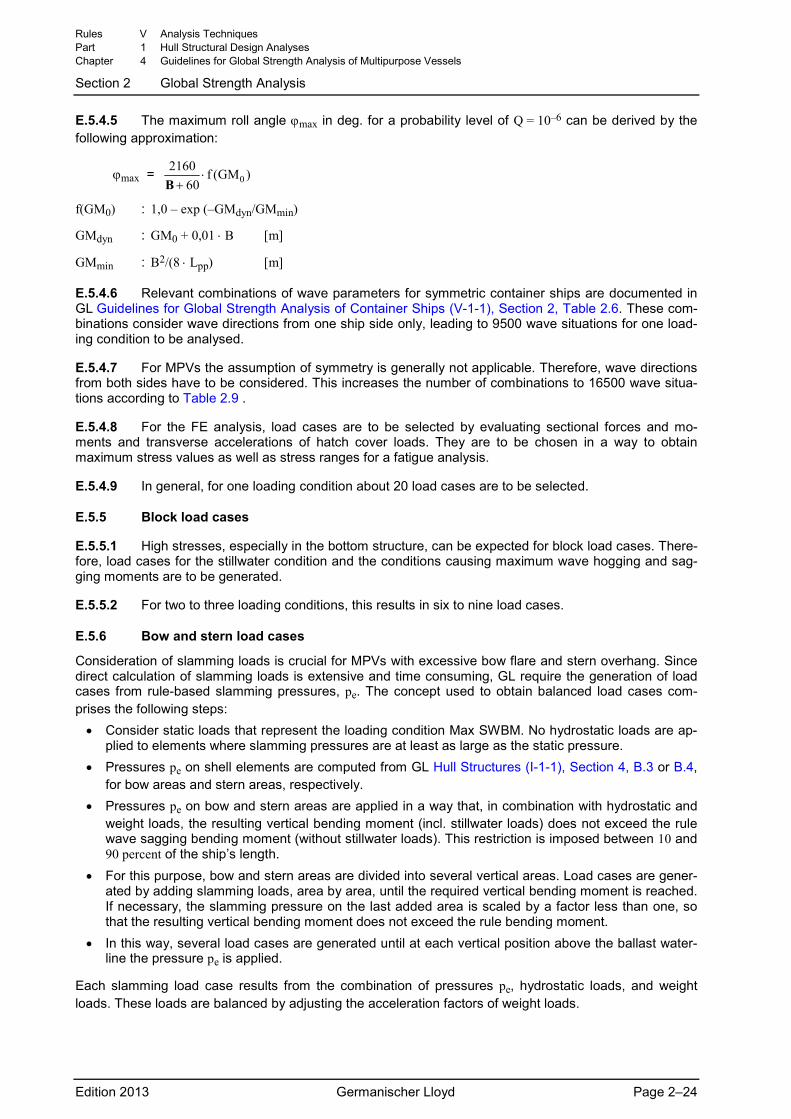
E.5.4.5 The maximum roll angle ϕmax in deg. for a probability level of Q = 10–6 can be derived by the following approximation:
ϕmax = 02160 f (GM )
60⋅
+B
f(GM0) : 1,0 – exp (–GMdyn/GMmin)
GMdyn : GM0 + 0,01 ⋅ B [m]
GMmin : B2/(8 ⋅ Lpp) [m]
E.5.4.6 Relevant combinations of wave parameters for symmetric container ships are documented in GL Guidelines for Global Strength Analysis of Container Ships (V-1-1), Section 2, Table 2.6. These com-binations consider wave directions from one ship side only, leading to 9500 wave situations for one load-ing condition to be analysed.
E.5.4.7 For MPVs the assumption of symmetry is generally not applicable. Therefore, wave directions from both sides have to be considered. This increases the number of combinations to 16500 wave situa-tions according to Table 2.9 .
E.5.4.8 For the FE analysis, load cases are to be selected by evaluating sectional forces and mo-ments and transverse accelerations of hatch cover loads. They are to be chosen in a way to obtain maximum stress values as well as stress ranges for a fatigue analysis.
E.5.4.9 In general, for one loading condition about 20 load cases are to be selected.
E.5.5 Block load cases
E.5.5.1 High stresses, especially in the bottom structure, can be expected for block load cases. There-fore, load cases for the stillwater condition and the conditions causing maximum wave hogging and sag-ging moments are to be generated.
E.5.5.2 For two to three loading conditions, this results in six to nine load cases.
E.5.6 Bow and stern load cases
Consideration of slamming loads is crucial for MPVs with excessive bow flare and stern overhang. Since direct calculation of slamming loads is extensive and time consuming, GL require the generation of load cases from rule-based slamming pressures, pe. The concept used to obtain balanced load cases com-prises the following steps:
• Consider static loads that represent the loading condition Max SWBM. No hydrostatic loads are ap-plied to elements where slamming pressures are at least as large as the static pressure.
• Pressures pe on shell elements are computed from GL Hull Structures (I-1-1), Section 4, B.3 or B.4, for bow areas and stern areas, respectively.
• Pressures pe on bow and stern areas are applied in a way that, in combination with hydrostatic and weight loads, the resulting vertical bending moment (incl. stillwater loads) does not exceed the rule wave sagging bending moment (without stillwater loads). This restriction is imposed between 10 and 90 percent of the ship’s length.
• For this purpose, bow and stern areas are divided into several vertical areas. Load cases are gener-ated by adding slamming loads, area by area, until the required vertical bending moment is reached. If necessary, the slamming pressure on the last added area is scaled by a factor less than one, so that the resulting vertical bending moment does not exceed the rule bending moment.
• In this way, several load cases are generated until at each vertical position above the ballast water-line the pressure pe is applied.
Each slamming load case results from the combination of pressures pe, hydrostatic loads, and weight loads. These loads are balanced by adjusting the acceleration factors of weight loads.
Rules V Analysis Techniques Part 1 Hull Structural Design Analyses Chapter 4 Guidelines for Global Strength Analysis of Multipurpose Vessels
Section 2 Global Strength Analysis
Edition 2013 Germanischer Lloyd Page 2–24
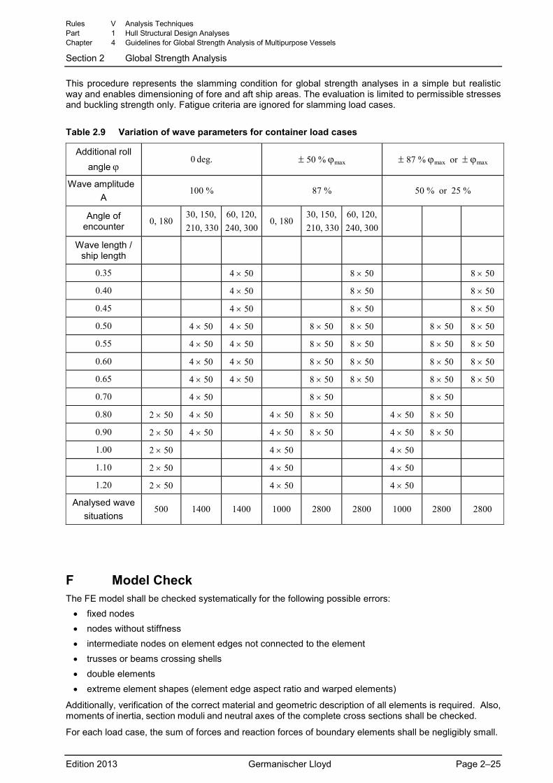
This procedure represents the slamming condition for global strength analyses in a simple but realistic way and enables dimensioning of fore and aft ship areas. The evaluation is limited to permissible stresses and buckling strength only. Fatigue criteria are ignored for slamming load cases.
Table 2.9 Variation of wave parameters for container load cases
Additional roll angle ϕ
0 deg. ± 50 % ϕmax ± 87 % ϕmax or ± ϕmax
Wave amplitude A
100 % 87 % 50 % or 25 %
Angle of encounter 0, 180
30, 150, 210, 330
60, 120, 240, 300
0, 180 30, 150,
210, 33060, 120, 240, 300
Wave length / ship length
0.35 4 × 50 8 × 50 8 × 50
0.40 4 × 50 8 × 50 8 × 50
0.45 4 × 50 8 × 50 8 × 50
0.50 4 × 50 4 × 50 8 × 50 8 × 50 8 × 50 8 × 50
0.55 4 × 50 4 × 50 8 × 50 8 × 50 8 × 50 8 × 50
0.60 4 × 50 4 × 50 8 × 50 8 × 50 8 × 50 8 × 50
0.65 4 × 50 4 × 50 8 × 50 8 × 50 8 × 50 8 × 50
0.70 4 × 50 8 × 50 8 × 50
0.80 2 × 50 4 × 50 4 × 50 8 × 50 4 × 50 8 × 50
0.90 2 × 50 4 × 50 4 × 50 8 × 50 4 × 50 8 × 50
1.00 2 × 50 4 × 50 4 × 50
1.10 2 × 50 4 × 50 4 × 50
1.20 2 × 50 4 × 50 4 × 50
Analysed wave situations
500 1400 1400 1000 2800 2800 1000 2800 2800
F Model Check The FE model shall be checked systematically for the following possible errors:
• fixed nodes • nodes without stiffness • intermediate nodes on element edges not connected to the element • trusses or beams crossing shells • double elements • extreme element shapes (element edge aspect ratio and warped elements)
Additionally, verification of the correct material and geometric description of all elements is required. Also, moments of inertia, section moduli and neutral axes of the complete cross sections shall be checked.
For each load case, the sum of forces and reaction forces of boundary elements shall be negligibly small.
Rules V Analysis Techniques Part 1 Hull Structural Design Analyses Chapter 4 Guidelines for Global Strength Analysis of Multipurpose Vessels
Section 2 Global Strength Analysis
Edition 2013 Germanischer Lloyd Page 2–25
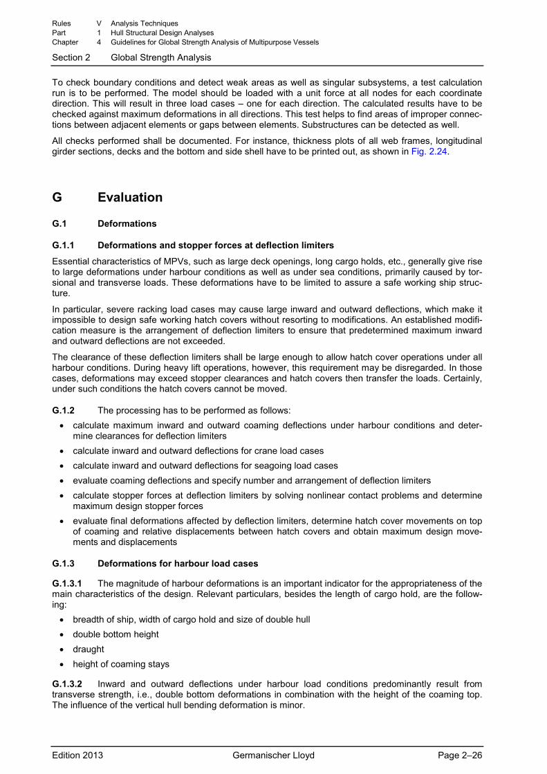
To check boundary conditions and detect weak areas as well as singular subsystems, a test calculation run is to be performed. The model should be loaded with a unit force at all nodes for each coordinate direction. This will result in three load cases – one for each direction. The calculated results have to be checked against maximum deformations in all directions. This test helps to find areas of improper connec-tions between adjacent elements or gaps between elements. Substructures can be detected as well.
All checks performed shall be documented. For instance, thickness plots of all web frames, longitudinal girder sections, decks and the bottom and side shell have to be printed out, as shown in Fig. 2.24.
G Evaluation
G.1 Deformations
G.1.1 Deformations and stopper forces at deflection limiters
Essential characteristics of MPVs, such as large deck openings, long cargo holds, etc., generally give rise to large deformations under harbour conditions as well as under sea conditions, primarily caused by tor-sional and transverse loads. These deformations have to be limited to assure a safe working ship struc-ture.
In particular, severe racking load cases may cause large inward and outward deflections, which make it impossible to design safe working hatch covers without resorting to modifications. An established modifi-cation measure is the arrangement of deflection limiters to ensure that predetermined maximum inward and outward deflections are not exceeded.
The clearance of these deflection limiters shall be large enough to allow hatch cover operations under all harbour conditions. During heavy lift operations, however, this requirement may be disregarded. In those cases, deformations may exceed stopper clearances and hatch covers then transfer the loads. Certainly, under such conditions the hatch covers cannot be moved.
G.1.2 The processing has to be performed as follows: • calculate maximum inward and outward coaming deflections under harbour conditions and deter-
mine clearances for deflection limiters • calculate inward and outward deflections for crane load cases • calculate inward and outward deflections for seagoing load cases • evaluate coaming deflections and specify number and arrangement of deflection limiters • calculate stopper forces at deflection limiters by solving nonlinear contact problems and determine
maximum design stopper forces • evaluate final deformations affected by deflection limiters, determine hatch cover movements on top
of coaming and relative displacements between hatch covers and obtain maximum design move-ments and displacements
G.1.3 Deformations for harbour load cases
G.1.3.1 The magnitude of harbour deformations is an important indicator for the appropriateness of the main characteristics of the design. Relevant particulars, besides the length of cargo hold, are the follow-ing:
• breadth of ship, width of cargo hold and size of double hull • double bottom height • draught • height of coaming stays
G.1.3.2 Inward and outward deflections under harbour load conditions predominantly result from transverse strength, i.e., double bottom deformations in combination with the height of the coaming top. The influence of the vertical hull bending deformation is minor.
Rules V Analysis Techniques Part 1 Hull Structural Design Analyses Chapter 4 Guidelines for Global Strength Analysis of Multipurpose Vessels
Section 2 Global Strength Analysis
Edition 2013 Germanischer Lloyd Page 2–26
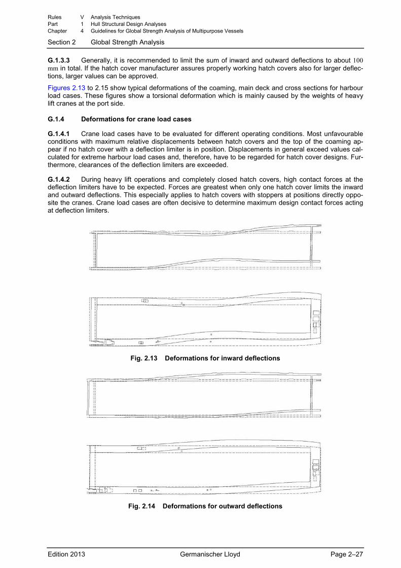
G.1.3.3 Generally, it is recommended to limit the sum of inward and outward deflections to about 100 mm in total. If the hatch cover manufacturer assures properly working hatch covers also for larger deflec-tions, larger values can be approved.
Figures 2.13 to 2.15 show typical deformations of the coaming, main deck and cross sections for harbour load cases. These figures show a torsional deformation which is mainly caused by the weights of heavy lift cranes at the port side.
G.1.4 Deformations for crane load cases
G.1.4.1 Crane load cases have to be evaluated for different operating conditions. Most unfavourable conditions with maximum relative displacements between hatch covers and the top of the coaming ap-pear if no hatch cover with a deflection limiter is in position. Displacements in general exceed values cal-culated for extreme harbour load cases and, therefore, have to be regarded for hatch cover designs. Fur-thermore, clearances of the deflection limiters are exceeded.
G.1.4.2 During heavy lift operations and completely closed hatch covers, high contact forces at the deflection limiters have to be expected. Forces are greatest when only one hatch cover limits the inward and outward deflections. This especially applies to hatch covers with stoppers at positions directly oppo-site the cranes. Crane load cases are often decisive to determine maximum design contact forces acting at deflection limiters.
Fig. 2.13 Deformations for inward deflections
Fig. 2.14 Deformations for outward deflections
Rules V Analysis Techniques Part 1 Hull Structural Design Analyses Chapter 4 Guidelines for Global Strength Analysis of Multipurpose Vessels
Section 2 Global Strength Analysis
Edition 2013 Germanischer Lloyd Page 2–27
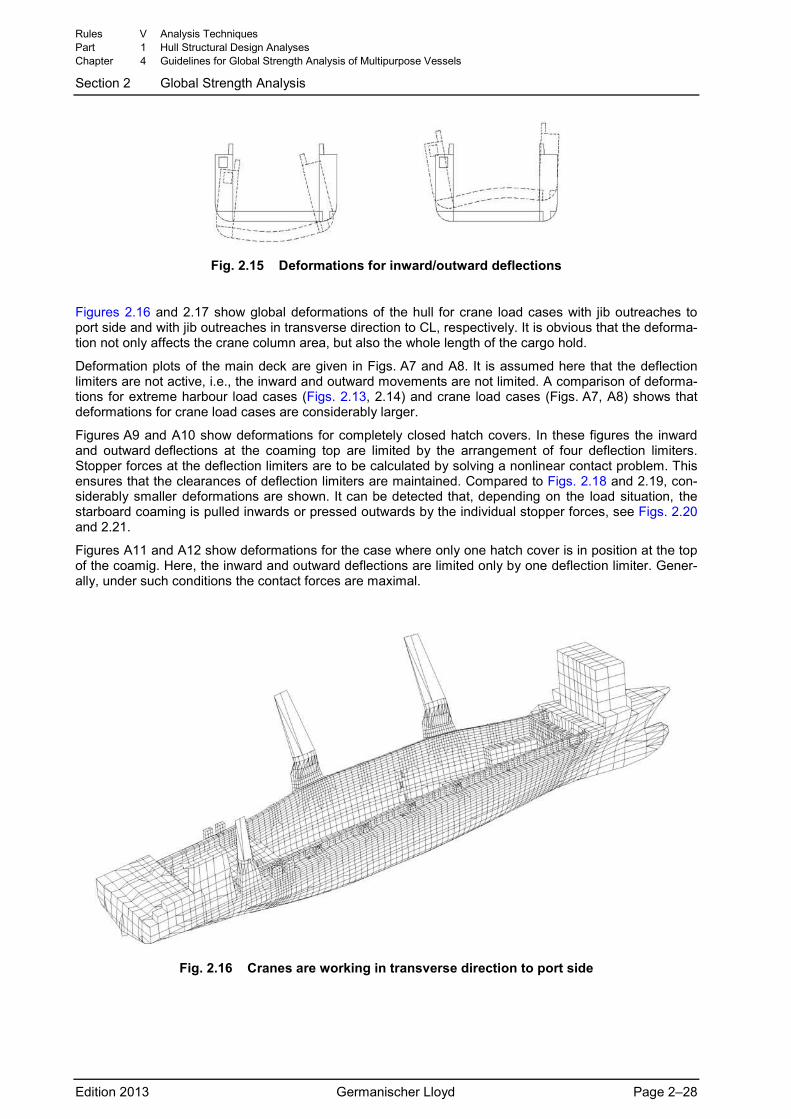
Fig. 2.15 Deformations for inward/outward deflections
Figures 2.16 and 2.17 show global deformations of the hull for crane load cases with jib outreaches to port side and with jib outreaches in transverse direction to CL, respectively. It is obvious that the deforma-tion not only affects the crane column area, but also the whole length of the cargo hold.
Deformation plots of the main deck are given in Figs. A7 and A8. It is assumed here that the deflection limiters are not active, i.e., the inward and outward movements are not limited. A comparison of deforma-tions for extreme harbour load cases (Figs. 2.13, 2.14) and crane load cases (Figs. A7, A8) shows that deformations for crane load cases are considerably larger.
Figures A9 and A10 show deformations for completely closed hatch covers. In these figures the inward and outward deflections at the coaming top are limited by the arrangement of four deflection limiters. Stopper forces at the deflection limiters are to be calculated by solving a nonlinear contact problem. This ensures that the clearances of deflection limiters are maintained. Compared to Figs. 2.18 and 2.19, con-siderably smaller deformations are shown. It can be detected that, depending on the load situation, the starboard coaming is pulled inwards or pressed outwards by the individual stopper forces, see Figs. 2.20 and 2.21.
Figures A11 and A12 show deformations for the case where only one hatch cover is in position at the top of the coamig. Here, the inward and outward deflections are limited only by one deflection limiter. Gener-ally, under such conditions the contact forces are maximal.
Fig. 2.16 Cranes are working in transverse direction to port side
Rules V Analysis Techniques Part 1 Hull Structural Design Analyses Chapter 4 Guidelines for Global Strength Analysis of Multipurpose Vessels
Section 2 Global Strength Analysis
Edition 2013 Germanischer Lloyd Page 2–28
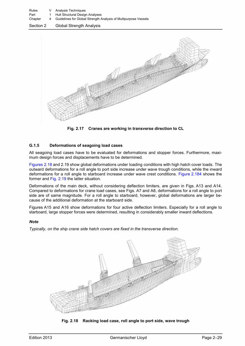
Fig. 2.17 Cranes are working in transverse direction to CL
G.1.5 Deformations of seagoing load cases
All seagoing load cases have to be evaluated for deformations and stopper forces. Furthermore, maxi-mum design forces and displacements have to be determined.
Figures 2.18 and 2.19 show global deformations under loading conditions with high hatch cover loads. The outward deformations for a roll angle to port side increase under wave trough conditions, while the inward deformations for a roll angle to starboard increase under wave crest conditions. Figure 2.184 shows the former and Fig. 2.19 the latter situation.
Deformations of the main deck, without considering deflection limiters, are given in Figs. A13 and A14. Compared to deformations for crane load cases, see Figs. A7 and A8, deformations for a roll angle to port side are of same magnitude. For a roll angle to starboard, however, global deformations are larger be-cause of the additional deformation at the starboard side.
Figures A15 and A16 show deformations for four active deflection limiters. Especially for a roll angle to starboard, large stopper forces were determined, resulting in considerably smaller inward deflections.
Note
Typically, on the ship crane side hatch covers are fixed in the transverse direction.
Fig. 2.18 Racking load case, roll angle to port side, wave trough
Rules V Analysis Techniques Part 1 Hull Structural Design Analyses Chapter 4 Guidelines for Global Strength Analysis of Multipurpose Vessels
Section 2 Global Strength Analysis
Edition 2013 Germanischer Lloyd Page 2–29
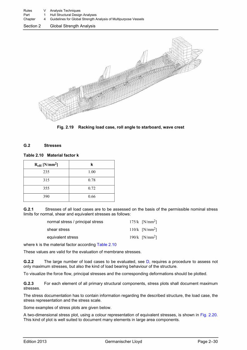
Fig. 2.19 Racking load case, roll angle to starboard, wave crest
G.2 Stresses
Table 2.10 Material factor k
ReH [N/mm2] k
235 1.00
315 0.78
355 0.72
390 0.66
G.2.1 Stresses of all load cases are to be assessed on the basis of the permissible nominal stress limits for normal, shear and equivalent stresses as follows:
normal stress / principal stress 175/k [N/mm2]
shear stress 110/k [N/mm2]
equivalent stress 190/k [N/mm2]
where k is the material factor according Table 2.10
These values are valid for the evaluation of membrane stresses.
G.2.2 The large number of load cases to be evaluated, see D, requires a procedure to assess not only maximum stresses, but also the kind of load bearing behaviour of the structure.
To visualize the force flow, principal stresses and the corresponding deformations should be plotted.
G.2.3 For each element of all primary structural components, stress plots shall document maximum stresses.
The stress documentation has to contain information regarding the described structure, the load case, the stress representation and the stress scale.
Some examples of stress plots are given below.
A two-dimensional stress plot, using a colour representation of equivalent stresses, is shown in Fig. 2.20. This kind of plot is well suited to document many elements in large area components.
Rules V Analysis Techniques Part 1 Hull Structural Design Analyses Chapter 4 Guidelines for Global Strength Analysis of Multipurpose Vessels
Section 2 Global Strength Analysis
Edition 2013 Germanischer Lloyd Page 2–30
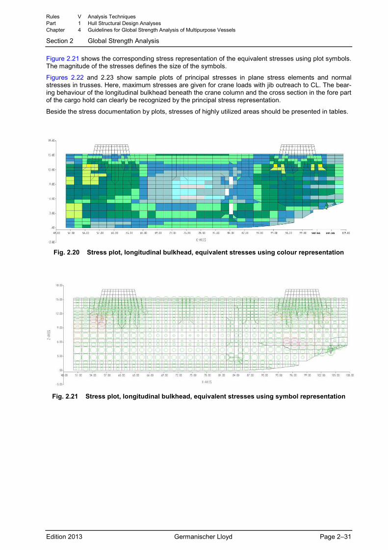
Figure 2.21 shows the corresponding stress representation of the equivalent stresses using plot symbols. The magnitude of the stresses defines the size of the symbols.
Figures 2.22 and 2.23 show sample plots of principal stresses in plane stress elements and normal stresses in trusses. Here, maximum stresses are given for crane loads with jib outreach to CL. The bear-ing behaviour of the longitudinal bulkhead beneath the crane column and the cross section in the fore part of the cargo hold can clearly be recognized by the principal stress representation.
Beside the stress documentation by plots, stresses of highly utilized areas should be presented in tables.
Fig. 2.20 Stress plot, longitudinal bulkhead, equivalent stresses using colour representation
Fig. 2.21 Stress plot, longitudinal bulkhead, equivalent stresses using symbol representation
Rules V Analysis Techniques Part 1 Hull Structural Design Analyses Chapter 4 Guidelines for Global Strength Analysis of Multipurpose Vessels
Section 2 Global Strength Analysis
Edition 2013 Germanischer Lloyd Page 2–31
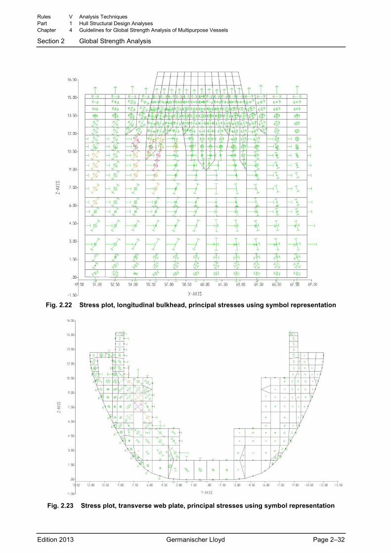
Fig. 2.22 Stress plot, longitudinal bulkhead, principal stresses using symbol representation
Fig. 2.23 Stress plot, transverse web plate, principal stresses using symbol representation
Rules V Analysis Techniques Part 1 Hull Structural Design Analyses Chapter 4 Guidelines for Global Strength Analysis of Multipurpose Vessels
Section 2 Global Strength Analysis
Edition 2013 Germanischer Lloyd Page 2–32
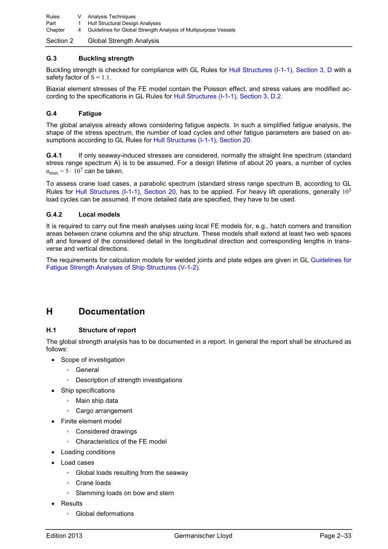
G.3 Buckling strength
Buckling strength is checked for compliance with GL Rules for Hull Structures (I-1-1), Section 3, D with a safety factor of S = 1.1.
Biaxial element stresses of the FE model contain the Poisson effect, and stress values are modified ac-cording to the specifications in GL Rules for Hull Structures (I-1-1), Section 3, D.2.
G.4 Fatigue
The global analysis already allows considering fatigue aspects. In such a simplified fatigue analysis, the shape of the stress spectrum, the number of load cycles and other fatigue parameters are based on as-sumptions according to GL Rules for Hull Structures (I-1-1), Section 20.
G.4.1 If only seaway-induced stresses are considered, normally the straight line spectrum (standard stress range spectrum A) is to be assumed. For a design lifetime of about 20 years, a number of cycles nmax = 5 ⋅ 107 can be taken.
To assess crane load cases, a parabolic spectrum (standard stress range spectrum B, according to GL Rules for Hull Structures (I-1-1), Section 20, has to be applied. For heavy lift operations, generally 105 load cycles can be assumed. If more detailed data are specified, they have to be used.
G.4.2 Local models
It is required to carry out fine mesh analyses using local FE models for, e.g., hatch corners and transition areas between crane columns and the ship structure. These models shall extend at least two web spaces aft and forward of the considered detail in the longitudinal direction and corresponding lengths in trans-verse and vertical directions.
The requirements for calculation models for welded joints and plate edges are given in GL Guidelines for Fatigue Strength Analyses of Ship Structures (V-1-2).
H Documentation
H.1 Structure of report
The global strength analysis has to be documented in a report. In general the report shall be structured as follows:
• Scope of investigation ◦ General ◦ Description of strength investigations
• Ship specifications ◦ Main ship data ◦ Cargo arrangement
• Finite element model ◦ Considered drawings ◦ Characteristics of the FE model
• Loading conditions • Load cases
◦ Global loads resulting from the seaway ◦ Crane loads ◦ Slamming loads on bow and stern
• Results ◦ Global deformations
Rules V Analysis Techniques Part 1 Hull Structural Design Analyses Chapter 4 Guidelines for Global Strength Analysis of Multipurpose Vessels
Section 2 Global Strength Analysis
Edition 2013 Germanischer Lloyd Page 2–33
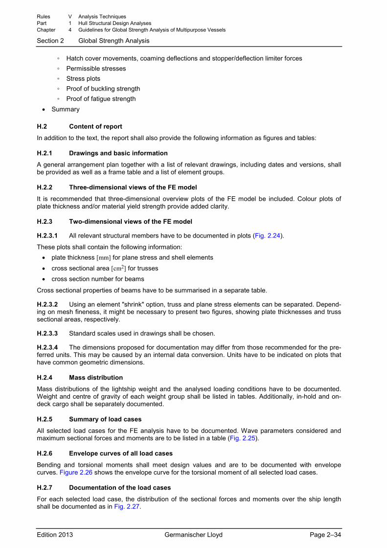
◦ Hatch cover movements, coaming deflections and stopper/deflection limiter forces ◦ Permissible stresses ◦ Stress plots ◦ Proof of buckling strength ◦ Proof of fatigue strength
• Summary
H.2 Content of report
In addition to the text, the report shall also provide the following information as figures and tables:
H.2.1 Drawings and basic information
A general arrangement plan together with a list of relevant drawings, including dates and versions, shall be provided as well as a frame table and a list of element groups.
H.2.2 Three-dimensional views of the FE model
It is recommended that three-dimensional overview plots of the FE model be included. Colour plots of plate thickness and/or material yield strength provide added clarity.
H.2.3 Two-dimensional views of the FE model
H.2.3.1 All relevant structural members have to be documented in plots (Fig. 2.24).
These plots shall contain the following information: • plate thickness [mm] for plane stress and shell elements
• cross sectional area [cm2] for trusses • cross section number for beams
Cross sectional properties of beams have to be summarised in a separate table.
H.2.3.2 Using an element "shrink" option, truss and plane stress elements can be separated. Depend-ing on mesh fineness, it might be necessary to present two figures, showing plate thicknesses and truss sectional areas, respectively.
H.2.3.3 Standard scales used in drawings shall be chosen.
H.2.3.4 The dimensions proposed for documentation may differ from those recommended for the pre-ferred units. This may be caused by an internal data conversion. Units have to be indicated on plots that have common geometric dimensions.
H.2.4 Mass distribution
Mass distributions of the lightship weight and the analysed loading conditions have to be documented. Weight and centre of gravity of each weight group shall be listed in tables. Additionally, in-hold and on-deck cargo shall be separately documented.
H.2.5 Summary of load cases
All selected load cases for the FE analysis have to be documented. Wave parameters considered and maximum sectional forces and moments are to be listed in a table (Fig. 2.25).
H.2.6 Envelope curves of all load cases
Bending and torsional moments shall meet design values and are to be documented with envelope curves. Figure 2.26 shows the envelope curve for the torsional moment of all selected load cases.
H.2.7 Documentation of the load cases
For each selected load case, the distribution of the sectional forces and moments over the ship length shall be documented as in Fig. 2.27.
Rules V Analysis Techniques Part 1 Hull Structural Design Analyses Chapter 4 Guidelines for Global Strength Analysis of Multipurpose Vessels
Section 2 Global Strength Analysis
Edition 2013 Germanischer Lloyd Page 2–34
H.2.8 Global deformation
To obtain an impression of the global deformation behaviour, overall deformations for every selected load case are to be documented in two-dimensional and three-dimensional views (Appendix A).
H.2.9 Stopper/deflection limiter forces
Stopper/deflection limiter forces have to be documented in tables.
H.2.10 Hatch cover deflection
One important result of the global strength analysis is the determination of the deformed hatch diagonal dimension and the determination of the hatch cover movements relative to the hatch coaming and relative to the adjacent hatch covers.
H.2.11 Fatigue of structural details
The fatigue results for hatch corners have to be summarised in tables.
H.2.12 Stress plots
Figure 2.28 shows a sample stress plot. The maximum stress of all load cases for each element shall be documented.
H.2.13 Buckling results
Buckling analysis for plate fields shall be documented.
H.2.14 Changes of the ship design
Proposed structural modifications, if necessary, shall be included in the report.
Rules V Analysis Techniques Part 1 Hull Structural Design Analyses Chapter 4 Guidelines for Global Strength Analysis of Multipurpose Vessels
Section 2 Global Strength Analysis
Edition 2013 Germanischer Lloyd Page 2–35
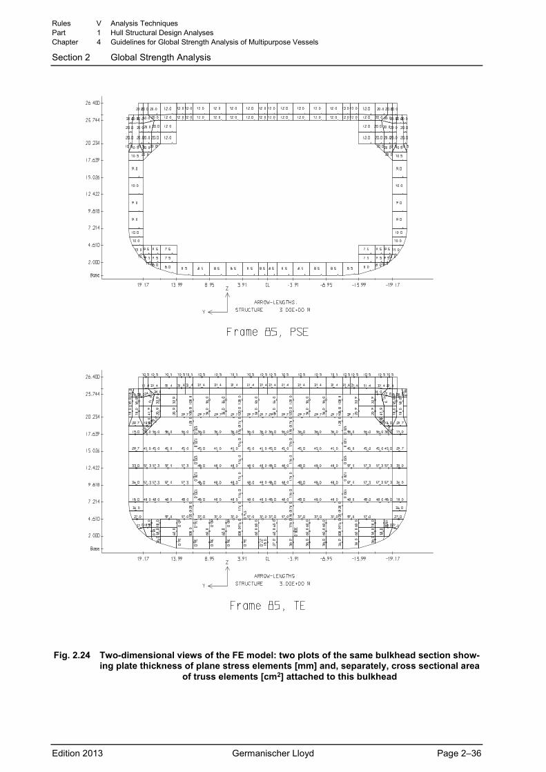
Fig. 2.24 Two-dimensional views of the FE model: two plots of the same bulkhead section show-
ing plate thickness of plane stress elements [mm] and, separately, cross sectional area of truss elements [cm2] attached to this bulkhead
Rules V Analysis Techniques Part 1 Hull Structural Design Analyses Chapter 4 Guidelines for Global Strength Analysis of Multipurpose Vessels
Section 2 Global Strength Analysis
Edition 2013 Germanischer Lloyd Page 2–36
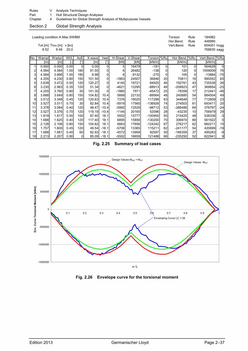
Loading condition A Max SWBM Torsion Rule 184982Hor.Bend. Rule 448990
Taft [m] Tfore [m] v [kn] Vert.Bend. Rule 654001 hogg8.52 8.49 20.0 768630 sagg
No. Wampl Wadyn Wl/L AoE X-wave heel H-Shear V-Shear Torsion %Ru Hor.Bend. %Ru Vert.Bend. %Ru[m] [m] [-] [°] [m] [°] [kN] [kN] [kN/m] [kN/m] [kN/m]
1 0.000 0.000 0.00 0 0.00 0 5 16479 -191 0 101 0 564628 02 4.584 4.584 1.00 180 91.55 0 6 26482 -136 0 120 0 1059009 763 4.584 3.666 1.00 180 8.98 0 6 -9132 -275 0 105 0 -13884 -754 4.255 4.230 0.80 150 101.50 0 -1863 24507 36846 20 70811 16 990552 655 3.638 3.472 0.50 120 120.27 0 4145 19721 84925 46 192761 43 735538 266 3.230 2.963 0.35 120 51.34 0 -4621 12295 -88913 48 -208923 47 369854 -257 4.255 3.760 0.80 30 141.30 0 -1885 7971 -45472 25 -78358 17 212441 -468 3.688 3.649 0.80 150 104.82 10.4 5668 22132 -89564 48 240880 54 884004 499 3.512 3.348 0.45 120 120.63 10.4 7376 19025 117298 63 344648 77 712609 23
10 3.527 3.511 0.70 30 82.84 10.4 -5919 17565 -136926 74 274503 61 693411 2011 3.378 3.064 0.40 120 48.47 -10.4 -5992 12529 -98712 53 -286489 64 376767 -2412 3.527 3.376 0.70 120 119.19 -10.4 -1144 20165 52096 28 -43235 10 756979 2913 1.819 1.817 0.50 150 87.40 18.1 5552 15777 -100950 55 215425 48 538338 -314 1.688 1.625 0.40 120 117.40 18.1 6895 15858 -130200 70 306974 68 561922 015 2.128 2.106 0.80 150 104.82 18.1 6663 17656 -124342 67 276217 62 660211 1516 1.757 1.600 0.45 120 49.54 -18.1 -5708 13365 115211 62 -241177 54 420699 -1917 1.688 1.681 0.40 60 82.93 -18.1 -4572 13958 92597 50 -166359 37 495283 -918 2.213 2.207 0.90 0 85.09 -18.1 -5502 16659 121488 66 -235292 52 622941 9
Fig. 2.25 Summary of load cases
-1500000
-1000000
-500000
0
500000
1000000
1500000
0 0.1 0.2 0.3 0.4 0.5 0.6 0.7 0.8 0.9 1
x / L
Env.
Cur
ve T
orsi
onal
Mom
ent [
kNm
]
Design Values MSW + MWTDesign Values MWT
Enveloping Curve LC 1-36
Fig. 2.26 Envelope curve for the torsional moment
Rules V Analysis Techniques Part 1 Hull Structural Design Analyses Chapter 4 Guidelines for Global Strength Analysis of Multipurpose Vessels
Section 2 Global Strength Analysis
Edition 2013 Germanischer Lloyd Page 2–37
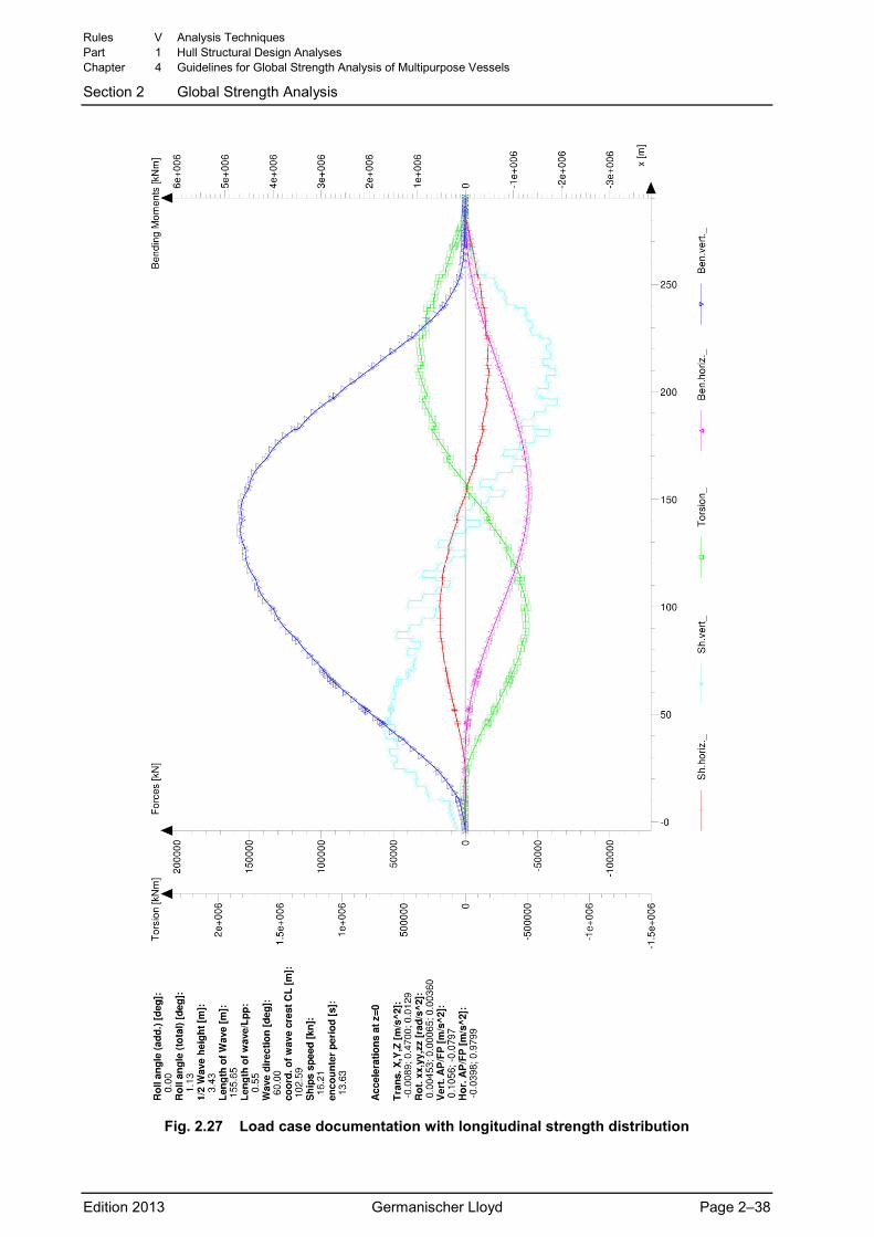
Fig. 2.27 Load case documentation with longitudinal strength distribution
Rules V Analysis Techniques Part 1 Hull Structural Design Analyses Chapter 4 Guidelines for Global Strength Analysis of Multipurpose Vessels
Section 2 Global Strength Analysis
Edition 2013 Germanischer Lloyd Page 2–38
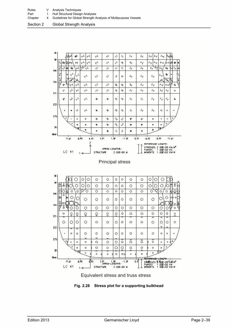
'�� �(�� ������
)*������� ������ � ����� ������
Fig. 2.28 Stress plot for a supporting bulkhead
Rules V Analysis Techniques Part 1 Hull Structural Design Analyses Chapter 4 Guidelines for Global Strength Analysis of Multipurpose Vessels
Section 2 Global Strength Analysis
Edition 2013 Germanischer Lloyd Page 2–39
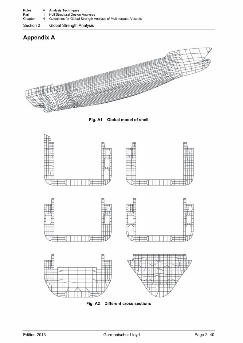
Appendix A
Fig. A1 Global model of shell
Fig. A2 Different cross sections
Rules V Analysis Techniques Part 1 Hull Structural Design Analyses Chapter 4 Guidelines for Global Strength Analysis of Multipurpose Vessels
Section 2 Global Strength Analysis
Edition 2013 Germanischer Lloyd Page 2–40
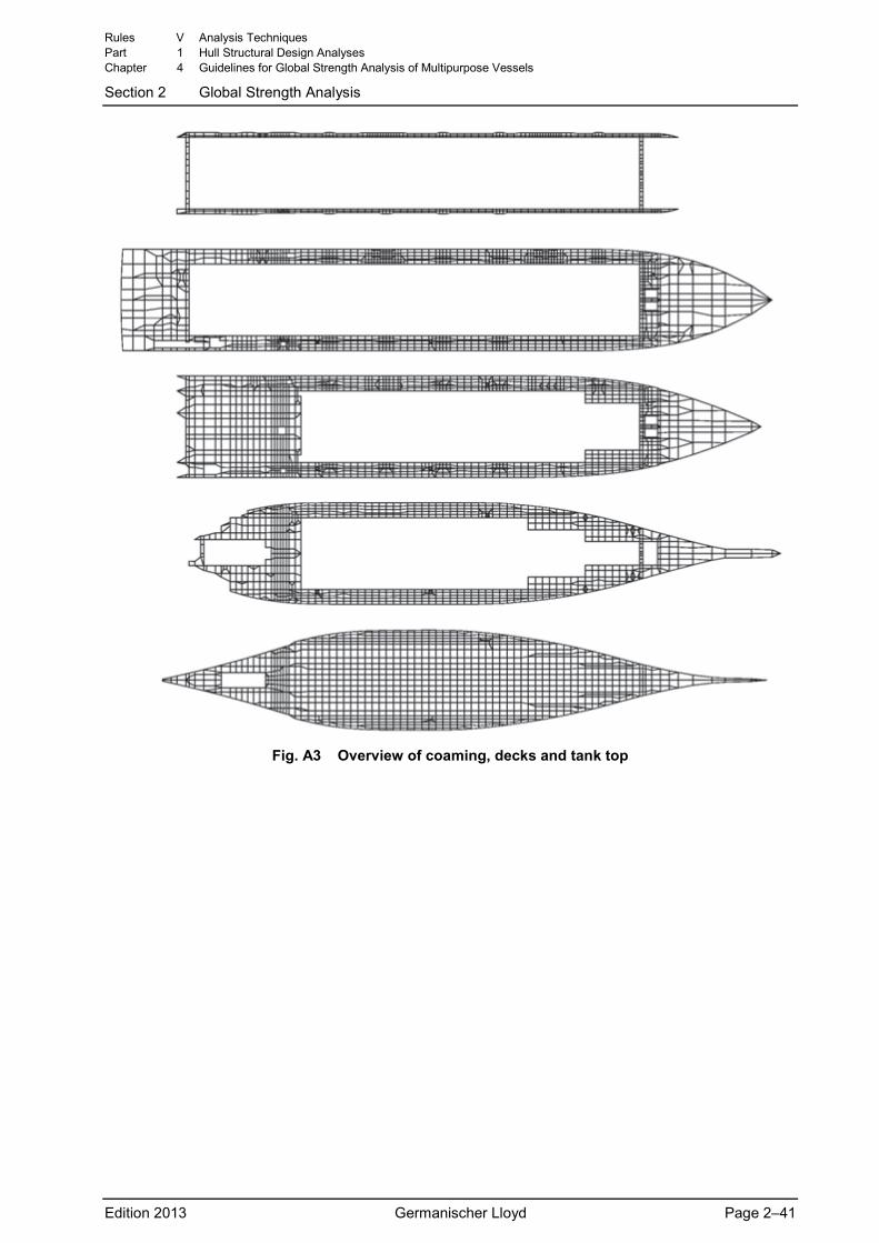
Fig. A3 Overview of coaming, decks and tank top
Rules V Analysis Techniques Part 1 Hull Structural Design Analyses Chapter 4 Guidelines for Global Strength Analysis of Multipurpose Vessels
Section 2 Global Strength Analysis
Edition 2013 Germanischer Lloyd Page 2–41
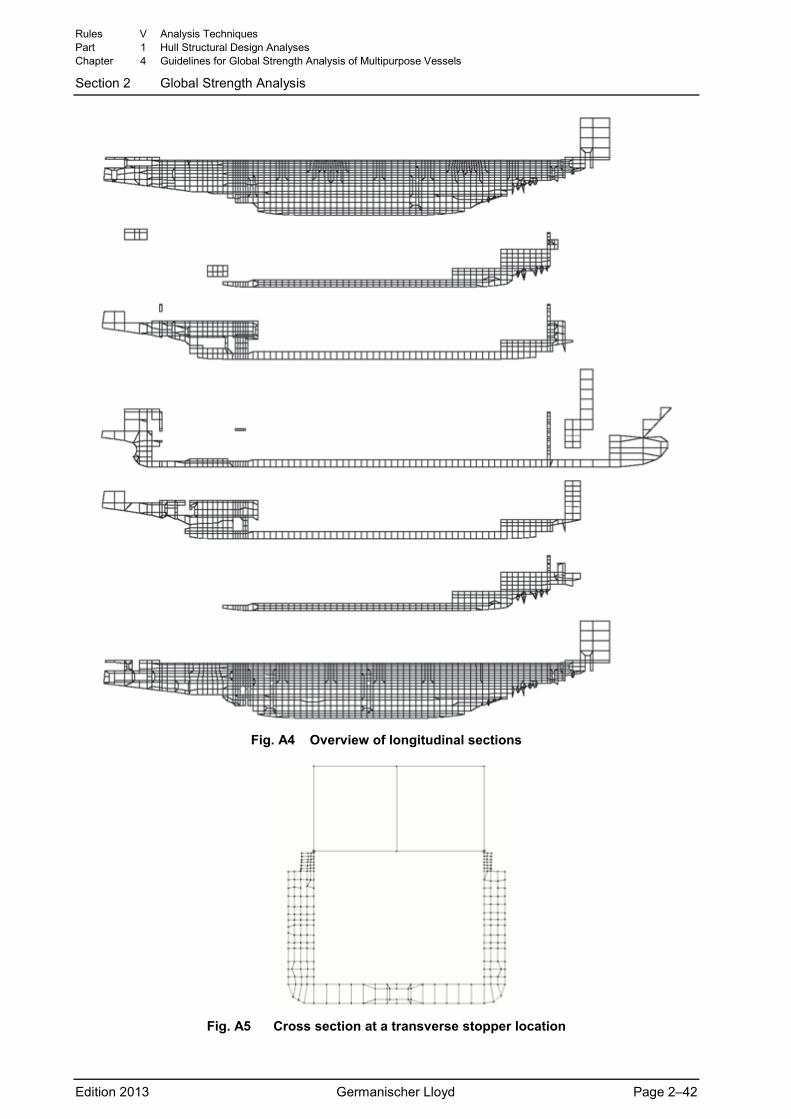
Fig. A4 Overview of longitudinal sections
Fig. A5 Cross section at a transverse stopper location
Rules V Analysis Techniques Part 1 Hull Structural Design Analyses Chapter 4 Guidelines for Global Strength Analysis of Multipurpose Vessels
Section 2 Global Strength Analysis
Edition 2013 Germanischer Lloyd Page 2–42
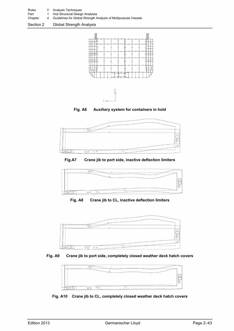
Fig. A6 Auxiliary system for containers in hold
Fig.A7 Crane jib to port side, inactive deflection limiters
Fig. A8 Crane jib to CL, inactive deflection limiters
Fig. A9 Crane jib to port side, completely closed weather deck hatch covers
Fig. A10 Crane jib to CL, completely closed weather deck hatch covers
Rules V Analysis Techniques Part 1 Hull Structural Design Analyses Chapter 4 Guidelines for Global Strength Analysis of Multipurpose Vessels
Section 2 Global Strength Analysis
Edition 2013 Germanischer Lloyd Page 2–43
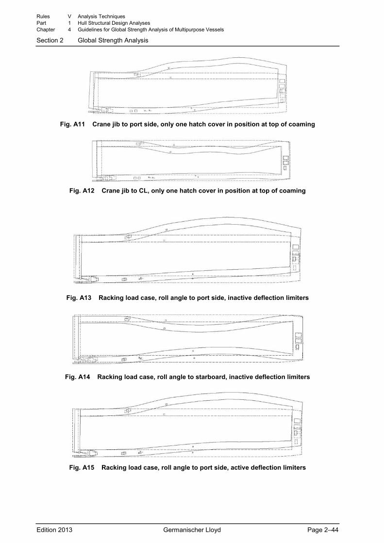
Fig. A11 Crane jib to port side, only one hatch cover in position at top of coaming
Fig. A12 Crane jib to CL, only one hatch cover in position at top of coaming
Fig. A13 Racking load case, roll angle to port side, inactive deflection limiters
Fig. A14 Racking load case, roll angle to starboard, inactive deflection limiters
Fig. A15 Racking load case, roll angle to port side, active deflection limiters
Rules V Analysis Techniques Part 1 Hull Structural Design Analyses Chapter 4 Guidelines for Global Strength Analysis of Multipurpose Vessels
Section 2 Global Strength Analysis
Edition 2013 Germanischer Lloyd Page 2–44
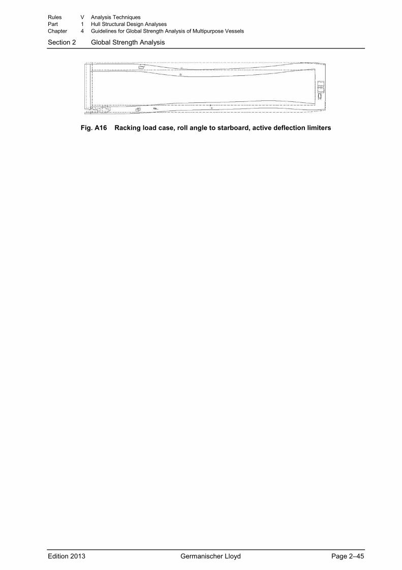
Fig. A16 Racking load case, roll angle to starboard, active deflection limiters
Rules V Analysis Techniques Part 1 Hull Structural Design Analyses Chapter 4 Guidelines for Global Strength Analysis of Multipurpose Vessels
Section 2 Global Strength Analysis
Edition 2013 Germanischer Lloyd Page 2–45

Section 3 Extended Scope of Analysis A General ....................................................................................................................... 3-1 B Tween Deck Load Cases............................................................................................ 3-1 C Crane Load Cases with Jib in Corner Position ........................................................... 3-1 D Grain Bulkhead Load Cases....................................................................................... 3-2
A General The scope of a standard global strength analysis of an MPV as described above can be extended by considering additional load cases and evaluation procedures. Requirements and details of an extended analysis shall be agreed upon between the involved parties.
The scope and extent of meaningful additional investigations and evaluation procedures depend on indi-vidual project objectives and design characteristics.
B Tween Deck Load Cases Appropriate load cases may be generated to assess the strength of highly loaded tween deck covers (covers loaded in excess of 5 t/m2) located either in middle or low positions inside the hold. The primary objective is to investigate, first, the overall strength of tween deck covers and, second, the buckling strength of the lower part of the longitudinal bulkhead and the supporting web frames in way of the tween deck cover bearings.
Generally, it may be sufficient to analyse only maximum wave hogging and wave sagging loading condi-tions (seagoing stillwater bending moments), whichever is more severe for the tween deck position. Usu-ally, two to four tween deck covers in middle as well as in low position shall be modelled as the basis for the corresponding load cases. These tween deck covers loaded with their maximum loads shall be lo-cated at a position where high global hull girder shear forces occur. Suitable auxiliary systems represent-ing the loaded tween deck covers and the corresponding bearing system at their correct locations have to be modelled to ensure a realistic loading idealisation.
Based on these loading conditions, load cases for the upright floating position shall be generated, cover-ing maximum (absolute) values of wave hogging and wave sagging bending moments. In addition, roll load cases with maximum heel to starboard and port side shall be set up for the wave hogging and wave sagging conditions.
If the analysis is restricted to modelling and investigating a length extending only over two to four selected tween deck covers, the results shall be extrapolated for an assessment over the entire cargo hold length.
C Crane Load Cases with Jib in Corner Position To comprehensively assess the fore and aft end walls of crane columns, additional crane load cases can be generated with the jib in a position directed towards the corners of the crane column. In this context, assessing the crane column itself is excluded from the standard scope of a global strength analysis of an MPV.
Generally, these additional crane load cases (and loading conditions) are derived from standard crane load cases described in GL Rules for Loading Gear on Seagoing Ships and Offshore Installations (VI-2-2) by modifying the jib directions from inward / outward to the corresponding positions directed towards the inward / outward corners of the crane column. Therefore, maximum hogging (at T and 0.7T) as well as maximum sagging (at T) loading conditions will be covered.
These additional crane load cases are primarily assessed for strength and fatigue. A fatigue assessment is focused on the corner of the crane column as well as on the transition structure between crane column and hull. Normally, buckling is of secondary interest. This kind of analysis does not replace the strength
Rules V Analysis Techniques Part 1 Hull Structural Design Analyses Chapter 4 Guidelines for Global Strength Analysis of Multipurpose Vessels
Section 3 Extended Scope of Analysis
Edition 2013 Germanischer Lloyd Page 3–1
proof of the crane column according GL rules for lifting devices GL Rules for Loading Gear on Seagoing Ships and Offshore Installations (VI-2-2), which is part of the approval process.
D Grain Bulkhead Load Cases To investigate and assess the hull structure surrounding the grain bulkhead bearings, special grain bulk-head loading conditions have to be generated, representing alternate loadings at grain bulkheads. Maxi-mum wave hogging and maximum wave sagging loading conditions shall be set up.
For these loading conditions, appropriate load cases shall be generated, covering wave hogging and wave sagging conditions for head and stern seas as well as for oblique seas.
Suitable auxiliary systems representing the grain bulkheads and the corresponding bearing system at their locations have to be modelled to ensure a realistic loading idealisation.
The evaluation is focussed on the strength and buckling assessment of the hull structure surrounding the grain bulkhead bearings, i.e., on the longitudinal bulkhead and web frames. Grain bulkheads themselves are normally excluded from this kind of assessment.
Rules V Analysis Techniques Part 1 Hull Structural Design Analyses Chapter 4 Guidelines for Global Strength Analysis of Multipurpose Vessels
Section 3 Extended Scope of Analysis
Edition 2013 Germanischer Lloyd Page 3–2