Embed Size (px)
Citation preview
Uwe Riechert 10/04/2012
IEEE PES Switchgear Committee, 2012 Fall Meeting 1
© ABB Group September 28, 2012 | Slide 1
Very Fast Transient Overvoltages (VFTO) inGas-Insulated EHV & UHV SubstationsTutorial of CIGRÉ Working Group A3.22 / A3.28Technical Requirements for UHV and EHV Substation Equipment
Uwe Riechert, ABB Switzerland Ltd, High Voltage Products, 2012-10-04
IEEE PES Switchgear Committee, 2012 Fall Meeting September 30 – October 4, 2012 Catamaran Resort Hotel, San Diego, CA, USA
© ABB Group September 28, 2012 | Slide 2
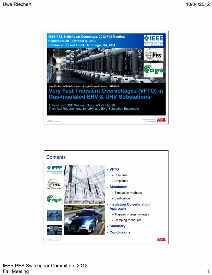
Contents
VFTO
Rise time
Amplitude
Simulation
Simulation methods
Verification
Insulation Co-ordination Approach
Trapped charge voltages
Damping measures
Summary
Conclusions
Uwe Riechert 10/04/2012
IEEE PES Switchgear Committee, 2012 Fall Meeting 2
© ABB Group September 28, 2012 | Slide 3
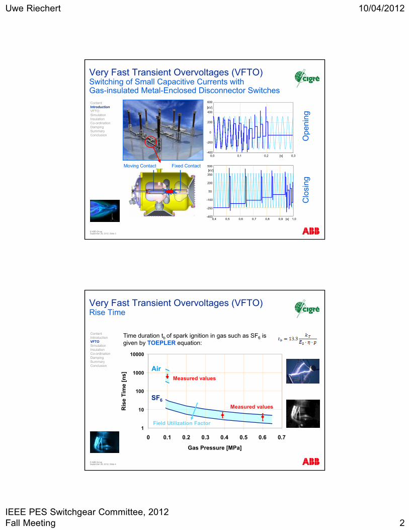
Very Fast Transient Overvoltages (VFTO) Switching of Small Capacitive Currents with Gas-insulated Metal-Enclosed Disconnector Switches
0,4 0,5 0,6 0,7 0,8 0,9 1,0[s]-400
-250
-100
50
200
350
500
[kV]
0,0 0,1 0,2 0,3-400
-200
0
200
400
600
[kV]
[s]
Fixed ContactMoving Contact
Ope
ning
Clo
sing
ContentIntroductionVFTOSimulationInsulation Co-ordinationDampingSummaryConclusion
Very Fast Transient Overvoltages (VFTO) Rise Time
Air
SF6
Measured values
Field Utilization Factor1
10
100
1000
10000
0 0.1 0.2 0.3 0.4 0.5 0.6 0.7
Gas Pressure [MPa]
Ris
e T
ime
[ns]
Measured values
Time duration tb of spark ignition in gas such as SF6 is given by TOEPLER equation:
© ABB Group September 28, 2012 | Slide 4
ContentIntroductionVFTOSimulationInsulation Co-ordinationDampingSummaryConclusion
Uwe Riechert 10/04/2012
IEEE PES Switchgear Committee, 2012 Fall Meeting 3
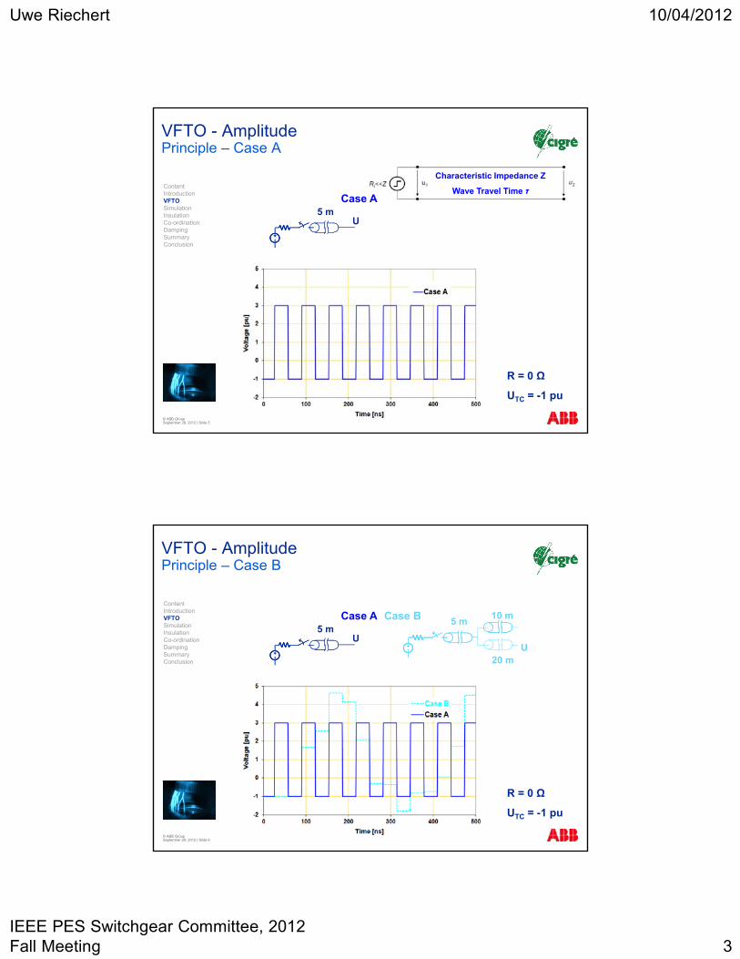
VFTO - Amplitude Principle – Case A
5 mU
R = 0 Ω
UTC = -1 pu
Characteristic Impedance Z
Wave Travel Time τ
© ABB Group September 28, 2012 | Slide 5
Case AContentIntroductionVFTOSimulationInsulation Co-ordinationDampingSummaryConclusion
VFTO - AmplitudePrinciple – Case B
5 mU
5 m
U
10 m
20 m
Case A Case B
R = 0 Ω
UTC = -1 pu
© ABB Group September 28, 2012 | Slide 6
ContentIntroductionVFTOSimulationInsulation Co-ordinationDampingSummaryConclusion
Uwe Riechert 10/04/2012
IEEE PES Switchgear Committee, 2012 Fall Meeting 4
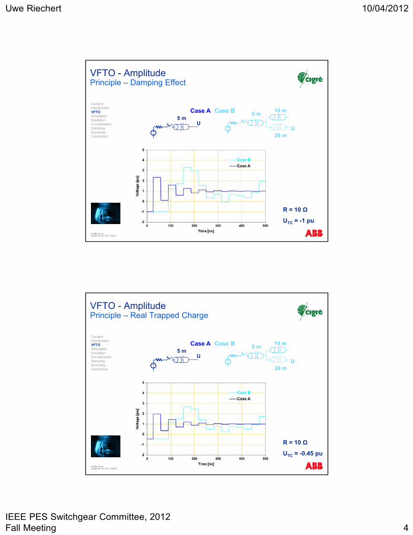
VFTO - AmplitudePrinciple – Damping Effect
5 mU
R = 10 Ω
UTC = -1 pu
5 m
U
10 m
20 m
© ABB Group September 28, 2012 | Slide 7
Case A Case BContentIntroductionVFTOSimulationInsulation Co-ordinationDampingSummaryConclusion
VFTO - Amplitude Principle – Real Trapped Charge
5 mU
R = 10 Ω
UTC = -0.45 pu
5 m
U
10 m
20 m
© ABB Group September 28, 2012 | Slide 8
Case A Case BContentIntroductionVFTOSimulationInsulation Co-ordinationDampingSummaryConclusion
Uwe Riechert 10/04/2012
IEEE PES Switchgear Committee, 2012 Fall Meeting 5
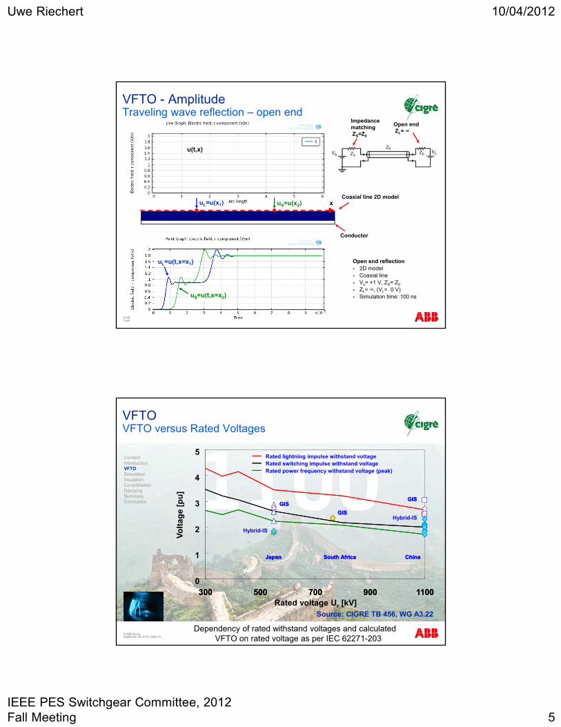
VFTO - Amplitude Traveling wave reflection – open end
© ABB Group September 28, 2012 | Slide 9
Open end reflection 2D model Coaxial line Vs= +1 V, ZS= Z0
ZL= ∞, (VL= 0 V) Simulation time: 100 ns
Coaxial line 2D model
Conductor
xuS=u(x2)uL=u(x1)
uL=u(t,x=x1)
uS=u(t,x=x2)
u(t,x)
Open endZL= ∞
ImpedancematchingZS=Z0
© ABB Group September 28, 2012 | Slide 10
VFTOVFTO versus Rated Voltages
Dependency of rated withstand voltages and calculated VFTO on rated voltage as per IEC 62271-203
Source: CIGRE TB 456, WG A3.22
0
1
4
5
300 500 700 900 1100Rated voltage Ur [kV]
Rated power frequency withstand voltage (peak)
Rated lightning impulse withstand voltage Rated switching impulse withstand voltage
Hybrid-IS
Hybrid-IS
Japan
GIS
GISGIS
South Africa China
300 500 700 900 1100
Japan
GIS
GISGIS
South Africa China
Vo
ltag
e [p
u]
2
3
ContentIntroductionVFTOSimulationInsulation Co-ordinationDampingSummaryConclusion
Uwe Riechert 10/04/2012
IEEE PES Switchgear Committee, 2012 Fall Meeting 6
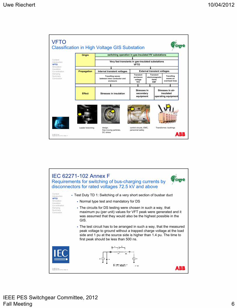
VFTOClassification in High Voltage GIS Substation
© ABB Group September 28, 2012 | Slide 11
Origin
Propagation Internal transient voltages
Travelling wavesbetween inner conductor and
enclosure
Effect Stresses in insulation
Transientenclosure
voltageTEV
Transientelectromagnetic
fieldsEMF
Travellingwaves on
overhead lines
Stresses insecondary equipment
Stresses in air-insulated
operating equipment
switching operation in gas-insulated HV substations
Very fast transients in gas-insulated substationsVFTO
External transient voltages
design, free moving particles,DC stress
control circuits, EMC,personnel safety
Transformer, bushingsLeader branching
ContentIntroductionVFTOSimulationInsulation Co-ordinationDampingSummaryConclusion
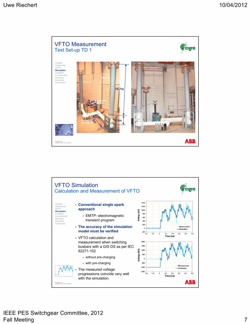
IEC 62271-102 Annex FRequirements for switching of bus-charging currents by disconnectors for rated voltages 72.5 kV and above
Test Duty TD 1: Switching of a very short section of busbar duct
Normal type test and mandatory for DS
The circuits for DS testing were chosen in such a way, that maximum pu (per unit) values for VFT peak were generated and it was assumed that they would also be the highest possible in the GIS.
The test circuit has to be arranged in such a way, that the measured peak voltage to ground without a trapped charge voltage at the load side and 1 pu at the source side is higher than 1.4 pu. The time to first peak should be less than 500 ns.
© ABB Group September 28, 2012 | Slide 12
ContentIntroductionVFTOSimulationInsulation Co-ordinationDampingSummaryConclusion
Uwe Riechert 10/04/2012
IEEE PES Switchgear Committee, 2012 Fall Meeting 7
VFTO Measurement Test Set-up TD 1
© ABB Group September 28, 2012 | Slide 13
10.7m
1.5m
ContentIntroductionVFTOSimulationInsulation Co-ordinationDampingSummaryConclusion
© ABB Group September 28, 2012 | Slide 14
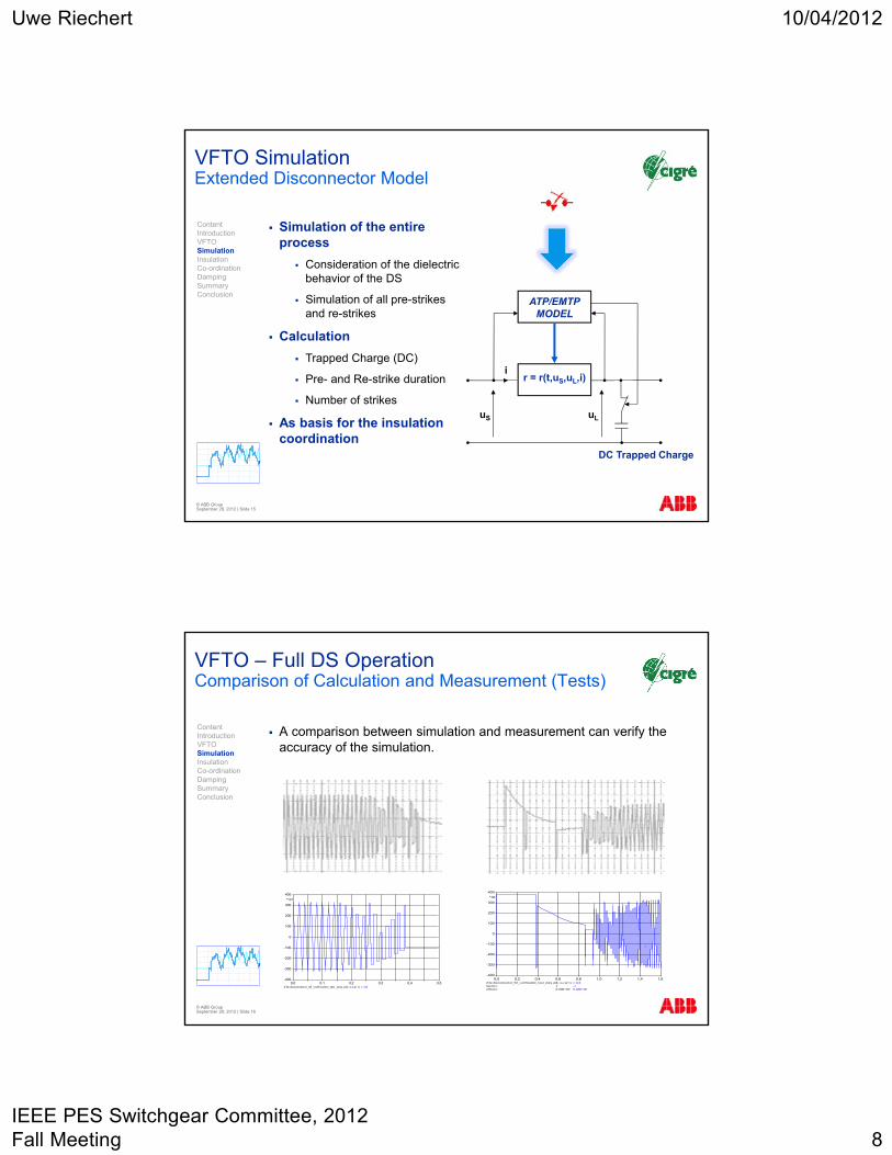
VFTO SimulationCalculation and Measurement of VFTO
Conventional single spark approach
EMTP- electromagnetic transient program
The accuracy of the simulation model must be verified
VFTO calculation and measurement when switching busbars with a GIS DS as per IEC 62271-102
without pre-charging
with pre-charging
The measured voltage progressions coincide very well with the simulation.
ContentIntroductionVFTOSimulationInsulation Co-ordinationDampingSummaryConclusion
Uwe Riechert 10/04/2012
IEEE PES Switchgear Committee, 2012 Fall Meeting 8
VFTO SimulationExtended Disconnector Model
ATP/EMTPMODEL
uL
r = r(t,uS,uL,i)
DC Trapped Charge
uS
i
Simulation of the entire process
Consideration of the dielectric behavior of the DS
Simulation of all pre-strikes and re-strikes
Calculation
Trapped Charge (DC)
Pre- and Re-strike duration
Number of strikes
As basis for the insulation coordination
© ABB Group September 28, 2012 | Slide 15
ContentIntroductionVFTOSimulationInsulation Co-ordinationDampingSummaryConclusion
VFTO – Full DS Operation Comparison of Calculation and Measurement (Tests)
A comparison between simulation and measurement can verify the accuracy of the simulation.
(f ile disconnector_03_v erif ication_test_duty .pl4; x-v ar t) v :U2 0,0 0,1 0,2 0,3 0,4 0,5
-400
-300
-200
-100
0
100
200
300
400
*103
(f ile disconnector_03_v erif ication_test_duty .pl4; x-v ar t) factors:offsets:
10,00E+00
v :U2 -10,00E+00
0,0 0,2 0,4 0,6 0,8 1,0 1,2 1,4 1,6-400
-300
-200
-100
0
100
200
300
400
*103
© ABB Group September 28, 2012 | Slide 16
ContentIntroductionVFTOSimulationInsulation Co-ordinationDampingSummaryConclusion
Uwe Riechert 10/04/2012
IEEE PES Switchgear Committee, 2012 Fall Meeting 9
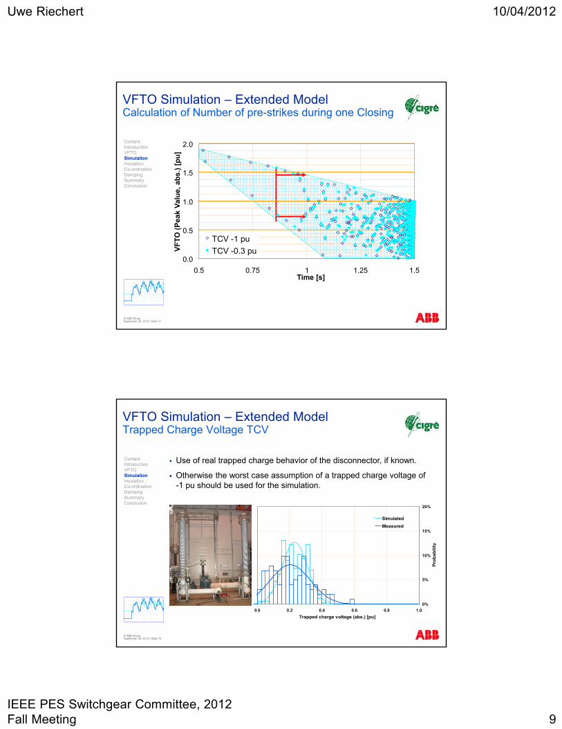
VFTO Simulation – Extended Model Calculation of Number of pre-strikes during one Closing
0.0
0.5
1.0
1.5
2.0
0.5 0.75 1 1.25 1.5Time [s]
VF
TO
(P
eak
Val
ue,
ab
s.)
[pu
]
TCV -1 pu
TCV -0.3 pu
© ABB Group September 28, 2012 | Slide 17
ContentIntroductionVFTOSimulationInsulation Co-ordinationDampingSummaryConclusion
© ABB Group September 28, 2012 | Slide 18
VFTO Simulation – Extended ModelTrapped Charge Voltage TCV
Use of real trapped charge behavior of the disconnector, if known.
Otherwise the worst case assumption of a trapped charge voltage of -1 pu should be used for the simulation.
0%
5%
10%
15%
20%
0.0 0.2 0.4 0.6 0.8 1.0
Trapped charge voltage (abs.) [pu]
Pro
ba
bil
ity
Simulated
Measured
ContentIntroductionVFTOSimulationInsulation Co-ordinationDampingSummaryConclusion
Uwe Riechert 10/04/2012
IEEE PES Switchgear Committee, 2012 Fall Meeting 10
© ABB Group September 28, 2012 | Slide 19
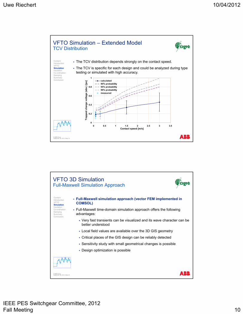
VFTO Simulation – Extended ModelTCV Distribution
The TCV distribution depends strongly on the contact speed.
The TCV is specific for each design and could be analyzed during type testing or simulated with high accuracy.
0
0.2
0.4
0.6
0.8
1
0 0.5 1 1.5 2 2.5 3 3.5Contact speed [m/s]
Tra
pp
ed
ch
arg
e v
olt
ag
e (
ab
s.)
[p
u] calculated
90% probability
95% probability
99% probability
measured
ContentIntroductionVFTOSimulationInsulation Co-ordinationDampingSummaryConclusion
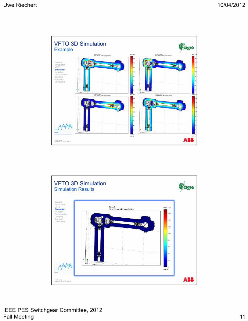
VFTO 3D Simulation Full-Maxwell Simulation Approach
Full-Maxwell simulation approach (vector FEM implemented in COMSOL)
Full-Maxwell time-domain simulation approach offers the following advantages:
Very fast transients can be visualized and its wave character can be better understood
Local field values are available over the 3D GIS geometry
Critical places of the GIS design can be reliably detected
Sensitivity study with small geometrical changes is possible
Design optimization is possible
© ABB Group September 28, 2012 | Slide 20
ContentIntroductionVFTOSimulationInsulation Co-ordinationDampingSummaryConclusion
Uwe Riechert 10/04/2012
IEEE PES Switchgear Committee, 2012 Fall Meeting 11
VFTO 3D Simulation Example
© ABB Group September 28, 2012 | Slide 21
ContentIntroductionVFTOSimulationInsulation Co-ordinationDampingSummaryConclusion
VFTO 3D SimulationSimulation Results
© ABB Group September 28, 2012 | Slide 22
ContentIntroductionVFTOSimulationInsulation Co-ordinationDampingSummaryConclusion
Uwe Riechert 10/04/2012
IEEE PES Switchgear Committee, 2012 Fall Meeting 12
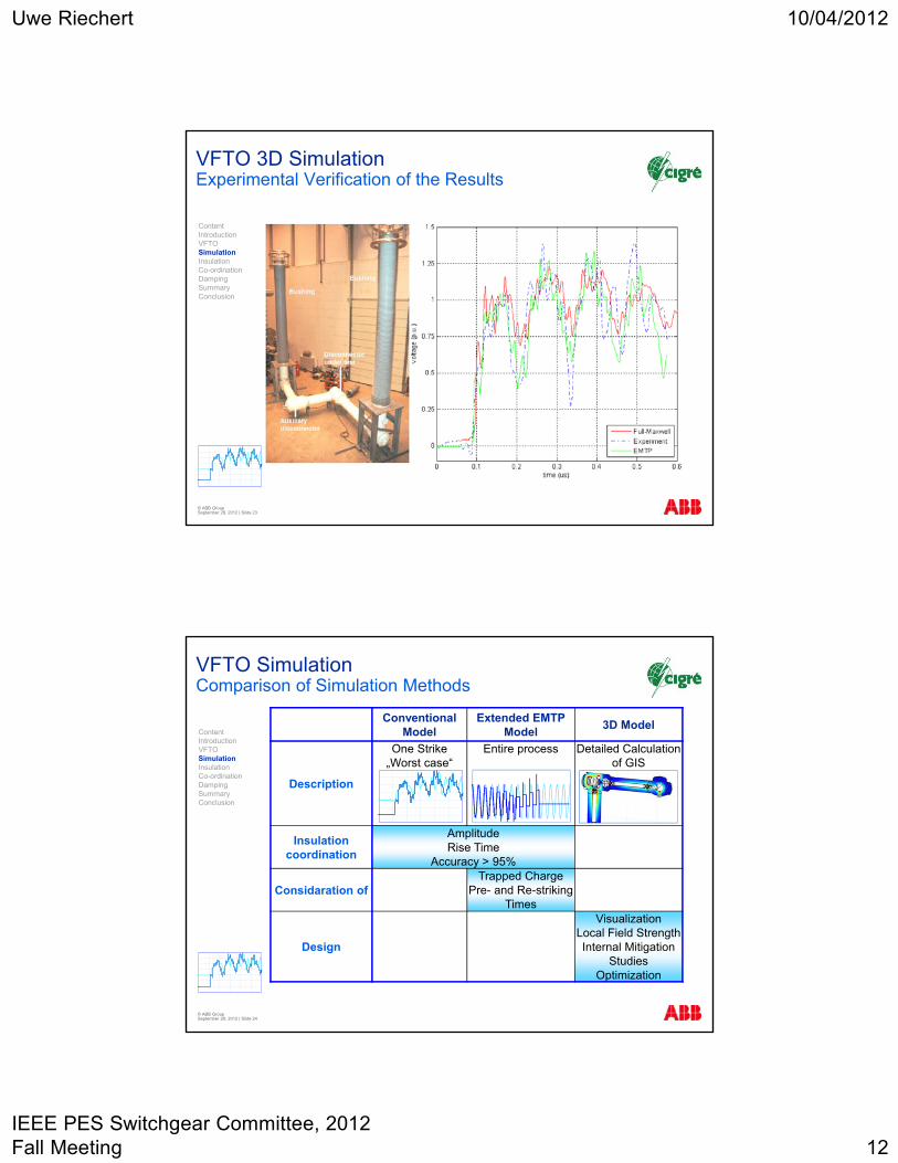
VFTO 3D Simulation Experimental Verification of the Results
© ABB Group September 28, 2012 | Slide 23
ContentIntroductionVFTOSimulationInsulation Co-ordinationDampingSummaryConclusion
VFTO Simulation Comparison of Simulation Methods
Conventional Model
Extended EMTP Model
3D Model
Description
One Strike „Worst case“
Entire process Detailed Calculation of GIS
Insulation coordination
AmplitudeRise Time
Accuracy > 95%
Considaration ofTrapped Charge
Pre- and Re-strikingTimes
Design
VisualizationLocal Field StrengthInternal Mitigation
StudiesOptimization
© ABB Group September 28, 2012 | Slide 24
ContentIntroductionVFTOSimulationInsulation Co-ordinationDampingSummaryConclusion
Uwe Riechert 10/04/2012
IEEE PES Switchgear Committee, 2012 Fall Meeting 13
© ABB Group September 28, 2012 | Slide 25
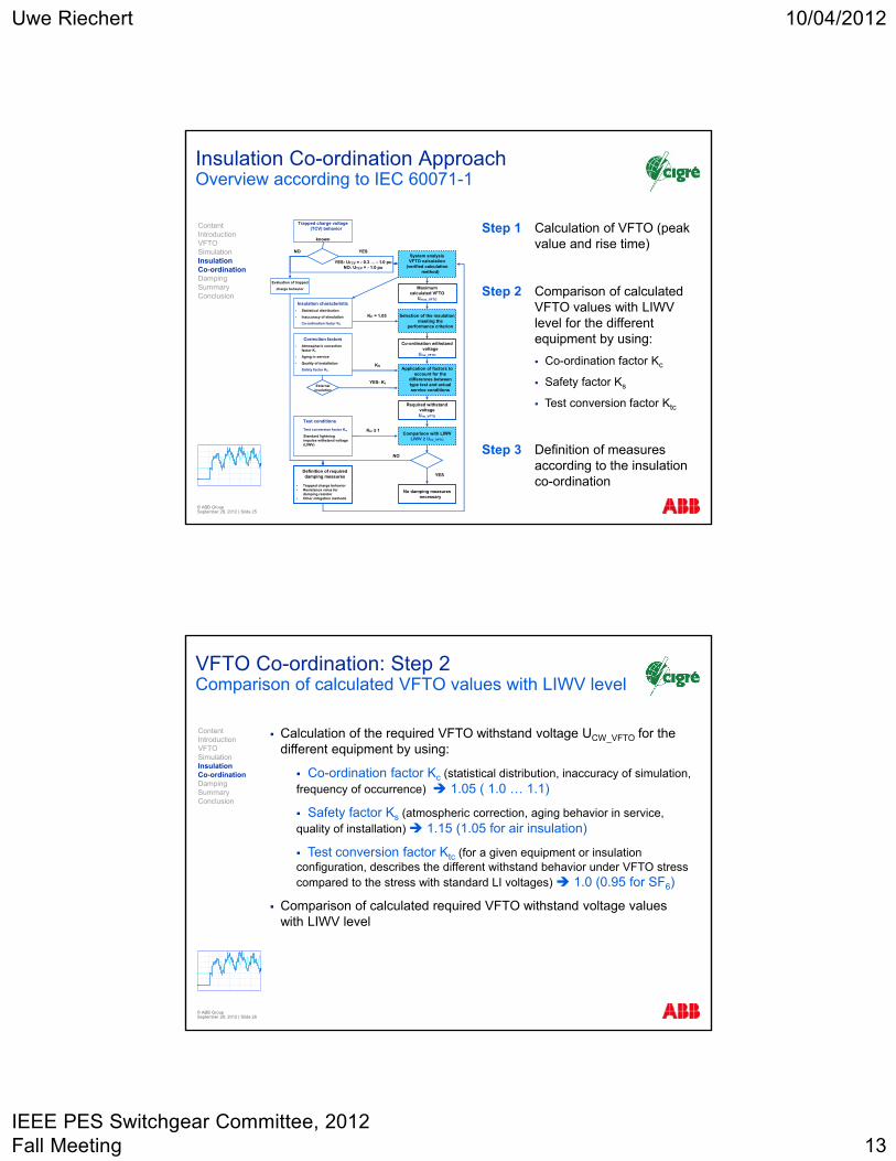
Insulation Co-ordination ApproachOverview according to IEC 60071-1
Step 1 Calculation of VFTO (peak value and rise time)
Step 2 Comparison of calculated VFTO values with LIWV level for the different equipment by using:
Co-ordination factor Kc
Safety factor Ks
Test conversion factor Ktc
Step 3 Definition of measures according to the insulation co-ordination
System analysisVFTO calculation
(verified calculation method)
Selection of the insulation meeting the
performance criterion
Application of factors to account for the
differences between type test and actual service conditions
Maximumcalculated VFTO
Umax_VFTO
Trapped charge voltage (TCV) behavior
known
YES
YES: UTCV = - 0.3 … - 1.0 puNO: UTCV = - 1.0 pu
Co-ordination withstand voltage
Ucw_VFTO
Insulation characteristic
Statistical distribution
Inaccuracy of simulation
Co-ordination factor KC
KC = 1.05
Required withstandvoltageUrw_VFTO
Correction factors
Atmospheric correction factor Kt
Aging in service
Quality of installation
Safety factor KS
YES: KtExternal
insulation
Test conditions
Test conversion factor Ktc
Standard lightning impulse withstand voltage (LIWV)
Ktc ≤ 1Comparison with LIWV
LIWV ≥ Urw_VFTO
No damping measures necessary
YESDefinition of requireddamping measures
Trapped charge behavior Resistance value for
damping resistor Other mitigation methods
NO
NO
Evaluation of trapped
charge behavior
KS
ContentIntroductionVFTOSimulationInsulation Co-ordinationDampingSummaryConclusion
VFTO Co-ordination: Step 2Comparison of calculated VFTO values with LIWV level
Calculation of the required VFTO withstand voltage UCW_VFTO for the different equipment by using:
Co-ordination factor Kc (statistical distribution, inaccuracy of simulation, frequency of occurrence) 1.05 ( 1.0 … 1.1)
Safety factor Ks (atmospheric correction, aging behavior in service, quality of installation) 1.15 (1.05 for air insulation)
Test conversion factor Ktc (for a given equipment or insulation configuration, describes the different withstand behavior under VFTO stress compared to the stress with standard LI voltages) 1.0 (0.95 for SF6)
Comparison of calculated required VFTO withstand voltage values with LIWV level
© ABB Group September 28, 2012 | Slide 26
ContentIntroductionVFTOSimulationInsulation Co-ordinationDampingSummaryConclusion
Uwe Riechert 10/04/2012
IEEE PES Switchgear Committee, 2012 Fall Meeting 14
© ABB Group September 28, 2012 | Slide 27
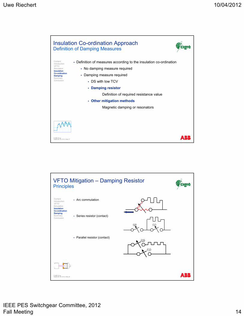
Insulation Co-ordination ApproachDefinition of Damping Measures
Definition of measures according to the insulation co-ordination
No damping measure required
Damping measure required
DS with low TCV
Damping resistor
Definition of required resistance value
Other mitigation methods
Magnetic damping or resonators
ContentIntroductionVFTOSimulationInsulation Co-ordinationDampingSummaryConclusion
VFTO Mitigation – Damping Resistor Principles
Arc commutation
Series resistor (contact)
Parallel resistor (contact)
(2) (1)
(1)
(2)
© ABB Group September 28, 2012 | Slide 28
ContentIntroductionVFTOSimulationInsulation Co-ordinationDampingSummaryConclusion
Uwe Riechert 10/04/2012
IEEE PES Switchgear Committee, 2012 Fall Meeting 15
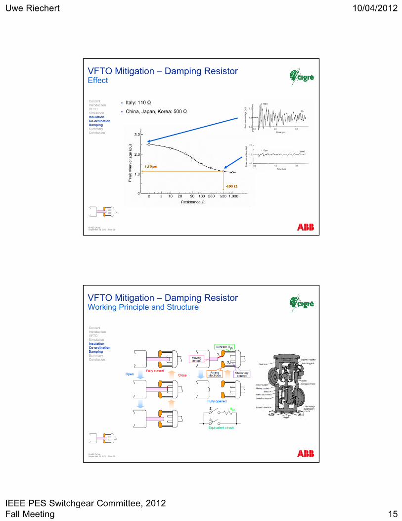
VFTO Mitigation – Damping Resistor Effect
Italy: 110 Ω
China, Japan, Korea: 500 Ω
© ABB Group September 28, 2012 | Slide 29
ContentIntroductionVFTOSimulationInsulation Co-ordinationDampingSummaryConclusion
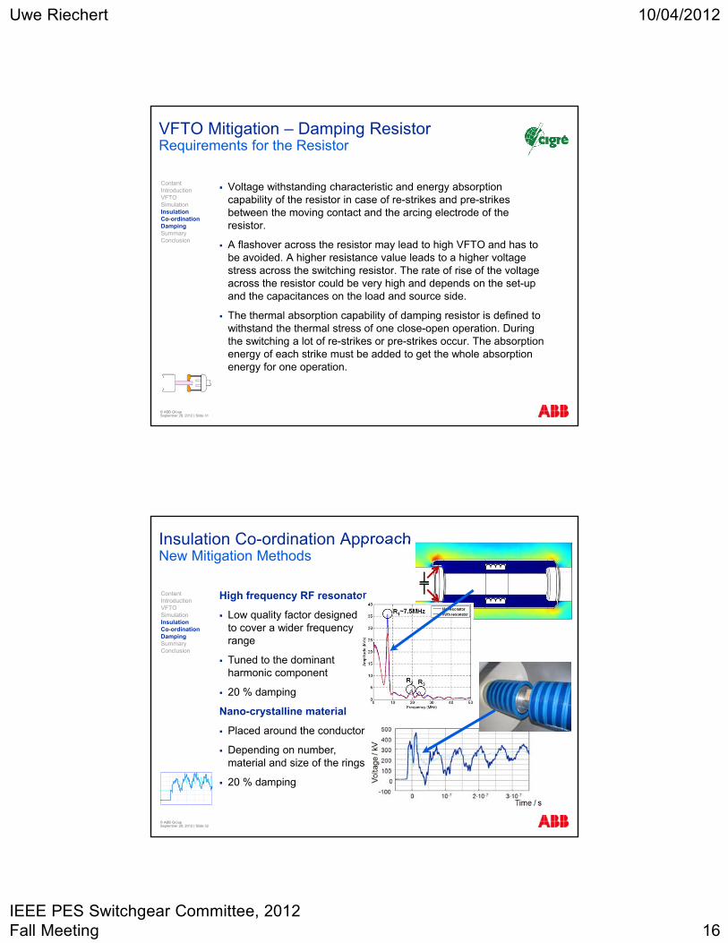
VFTO Mitigation – Damping Resistor Working Principle and Structure
© ABB Group September 28, 2012 | Slide 30
ContentIntroductionVFTOSimulationInsulation Co-ordinationDampingSummaryConclusion
Uwe Riechert 10/04/2012
IEEE PES Switchgear Committee, 2012 Fall Meeting 16
VFTO Mitigation – Damping Resistor Requirements for the Resistor
Voltage withstanding characteristic and energy absorption capability of the resistor in case of re-strikes and pre-strikes between the moving contact and the arcing electrode of the resistor.
A flashover across the resistor may lead to high VFTO and has to be avoided. A higher resistance value leads to a higher voltage stress across the switching resistor. The rate of rise of the voltage across the resistor could be very high and depends on the set-up and the capacitances on the load and source side.
The thermal absorption capability of damping resistor is defined to withstand the thermal stress of one close-open operation. During the switching a lot of re-strikes or pre-strikes occur. The absorption energy of each strike must be added to get the whole absorption energy for one operation.
© ABB Group September 28, 2012 | Slide 31
ContentIntroductionVFTOSimulationInsulation Co-ordinationDampingSummaryConclusion
© ABB Group September 28, 2012 | Slide 32
Insulation Co-ordination ApproachNew Mitigation Methods
High frequency RF resonator
Low quality factor designed to cover a wider frequency range
Tuned to the dominant harmonic component
20 % damping
Nano-crystalline material
Placed around the conductor
Depending on number, material and size of the rings
20 % damping
ContentIntroductionVFTOSimulationInsulation Co-ordinationDampingSummaryConclusion
Uwe Riechert 10/04/2012
IEEE PES Switchgear Committee, 2012 Fall Meeting 17
© ABB Group September 28, 2012 | Slide 33
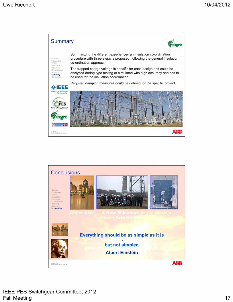
Summary
Summarizing the different experiences an insulation co-ordination procedure with three steps is proposed, following the general insulation co-ordination approach.
The trapped charge voltage is specific for each design and could be analyzed during type testing or simulated with high accuracy and has to be used for the insulation coordination.
Required damping measures could be defined for the specific project.
ContentIntroductionVFTOSimulationInsulation Co-ordinationDampingSummaryConclusion
© ABB Group September 28, 2012 | Slide 34
Conclusions
Everything should be as simple as it is-
but not simpler.
Albert Einstein
ContentIntroductionVFTOSimulationInsulation Co-ordinationDampingSummaryConclusion
Uwe Riechert 10/04/2012
IEEE PES Switchgear Committee, 2012 Fall Meeting 18
© ABB Group September 28, 2012 | Slide 35
CIGRÉUHV Working Groups
ContentIntroductionVFTOSimulationInsulation Co-ordinationDampingSummaryConclusion
(1) CIGRÉ WG A3.22: Technical Requirements for Substation Equipment Exceeding 800 kV – TB 362 & TB 456
(2) CIGRÉ WG B3.22: Technical Requirement for Substations Exceeding 800 kV –TB 400
(3) CIGRÉ Ad Hoc TF of SC D1: VFTO in UHV GIS Systems
(4) CIGRÉ WG D1.36: Special Requirements for Dielectric Testing of Ultra High Voltage (UHV) Equipment
(5) CIGRÉ WG C4.306: Insulation Coordination for UHV AC Systems
(6) CIGRÉ WG A3.28: Switching phenomena and testing requirements for UHV & EHV equipment
(7) CIGRÉ WG B3.27: Field tests technology on UHV substation during construction and operation
© ABB Group September 28, 2012 | Slide 36
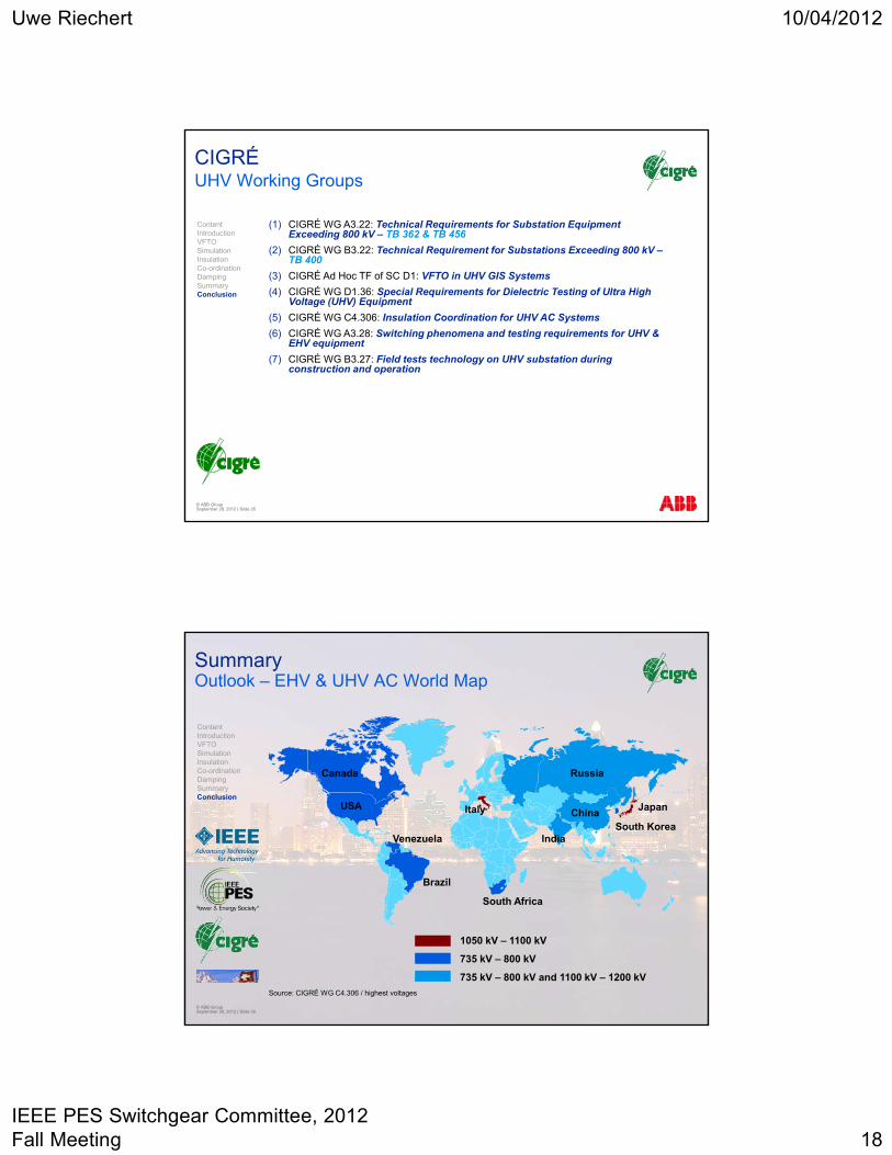
SummaryOutlook – EHV & UHV AC World Map
ContentIntroductionVFTOSimulationInsulation Co-ordinationDampingSummaryConclusion
RussiaCanada
USA
Venezuela
Brazil
South Africa
Italy ChinaJapan
South KoreaIndia
Source: CIGRÉ WG C4.306 / highest voltages
1050 kV – 1100 kV
735 kV – 800 kV
735 kV – 800 kV and 1100 kV – 1200 kV
Uwe Riechert 10/04/2012
IEEE PES Switchgear Committee, 2012 Fall Meeting 19
© ABB Group September 28, 2012 | Slide 37
AuthorCV Dr.-Ing. Uwe Riechert
ContentIntroductionVFTOSimulationInsulation Co-ordinationDampingSummaryConclusion
Studies in electrical engineering at the Dresden Technical University
Research assistant at the Dresden Technical University
Diagnostics and dielectric properties of polymeric insulated cables for ac and dc applications
PhD on the topic of polymeric insulated HVDC cables in 2001
Since 1999 ABB Switzerland Ltd
Up to 2001: test engineer in the high voltage laboratory
Since 2001: switchgear development, responsible for partial discharge diagnostic and monitoring, solid insulating materials, dielectric design, patents, testing, product certification and cooperation with research centers and universities
Since 2004: development project manager (e.g. 1100 kV circuit-breaker)
2008: senior manager
2009-2011: high current systems (generator circuit breaker) development
Since 2011: gas insulated switchgear development
Membership
DKE (German Commission for Electrical, Electronic & Information Technologies of DIN and VDE)
Swiss Electrotechnical Committee (CES) TK42 (convener) and TK115 (convener)
CIGRÉ working groups (AG D1.03, WG A3.28, WG D1.25, WG D1.28, WG C4.306).
Convener of CIGRÉ working group D1.36: Special requirements for dielectric testing of Ultra High Voltage (UHV) equipment
IEC TC42/WG19
email: [email protected]
© ABB Group September 28, 2012 | Slide 38