Embed Size (px)
Citation preview
UVC 102, 103: Dynamic flow control system with 2-way or 3-way valve and energy monitoring, eValveco
How energy efficiency is improvedThe SAUTER eValveco flow control system is the energy-efficient solution for variable flow controland energy monitoring
Features• Pressure-independent variable flow control• Dynamic hydronic balancing at full and partial load• Energy monitoring• Integrated flow measurement with feedback and temperature measurement• Remote commissioning and troubleshooting• With integrated LCD and operating panel• Available as 2-way or 3-way ball valve version, DN15 ... DN50• For variable-flow HVAC systems
Technical data
Electronic power supplyPower supply Uv: 24 V~ (±20%) 50 Hz
Power consumption during operation 2.5 W (3 VA)Power consumption when idle 1.0 W (1.5 VA)Peak inrush current 6.4 AInput signal Y1: 0...10 V=
Ri ≥ 60 kΩFeedback signal1) X1: 0...10 V= (max. 2 mA)
Feedback signal resolution Approx. 100 mV
Volume flow controlSetpoint adjustment Analogue (Y1) or via Modbus or oper-
ating panelType of sensor TTM ultrasonic sensor, no moving
partsUnit of measurement2) [m3/h], l/s, l/min, gpm (UK),
gpm (US)Measuring accuracy3) ±3% of actual valueMinimum controllable flow 17...70 l/hReadiness for operation 5-10 minutes after switching on
Valve and actuatorNominal pressure PN16 (16 bar)Differential pressure ∆p Max. 2.4 barMedium4) Water (glycol-free)Temperature of medium 5 °C...90 °CLeakage rate in % of Kvs 0.001 %
Temperature sensorMeasuring element Pt500 as per EN 60751, Class B
Interfaces and communicationBus connector STP cable, 2x double twisted
BMS integration Protocol Modbus/RTU, slaveConnection RS-485 double twisted cable (with
shared lead)Cable type Shielded 2-core cable, STP or FTPBaud rate 9600, 19 200 or 38 400
1) In relation to the measured actual flow2) Unit in [ ]: Factory setting3) In relation to the measured actual flow4) In accordance with VDI 2035 sheet 2
Product data sheet 1.1 57.011
Right of amendment reserved © 2018 Fr. Sauter AG 1/11
M
~
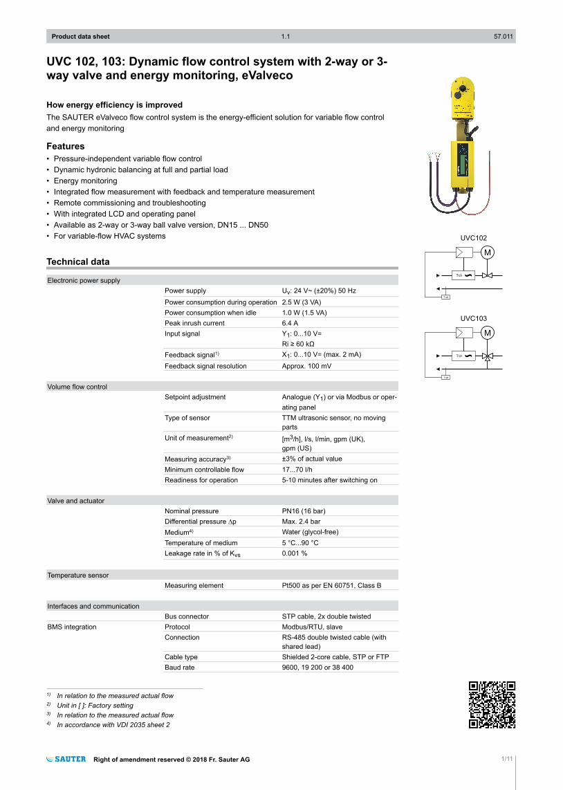
UVC102
T
T
M
~
UVC103
T
T
Terminating resistor 120 Ω both sides
Flow meter designHousing material Polypropylene, steel
Water-bearing parts:Pressed brass DN 15 CW617N, DN 20 - 50 CW602N (DZR), bronze,EPDM seal, stainless steel, EN-JM1130 fitting as per EN1562
LCD Backlit liquid crystal display, 2x16characters
Ambient conditionsAdmissible ambient temperature 10...45 °CAdmissible storage temperature -20...50 °CAdmissible ambient humidity Max. 90% rh, non-condensing
Standards and directivesType of protection5) IP54 (EN 60529), horizontal
CE conformity according to EMC Directive 2014/30/EU EN 61000-6-3 (2007)EN 61000-3-2 (2006)EN 61000-3-3 (1995) + am1 (2001)EN 61000-6-1 (2005)
PED 2014/68/EU Fluid group II, no CE label
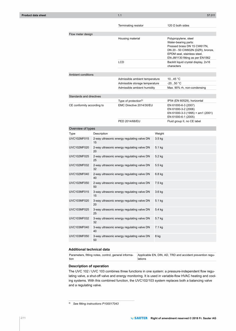
Overview of typesType Description Weight
UVC102MF015 2-way ultrasonic energy regulating valve DN15
3.5 kg
UVC102MF020 2-way ultrasonic energy regulating valve DN20
5.1 kg
UVC102MF025 2-way ultrasonic energy regulating valve DN25
5.2 kg
UVC102MF032 2-way ultrasonic energy regulating valve DN32
5.5 kg
UVC102MF040 2-way ultrasonic energy regulating valve DN40
6.8 kg
UVC102MF050 2-way ultrasonic energy regulating valve DN50
7.5 kg
UVC103MF015 3-way ultrasonic energy regulating valve DN15
3.6 kg
UVC103MF020 3-way ultrasonic energy regulating valve DN20
5.1 kg
UVC103MF025 3-way ultrasonic energy regulating valve DN25
5.4 kg
UVC103MF032 3-way ultrasonic energy regulating valve DN32
5.7 kg
UVC103MF040 3-way ultrasonic energy regulating valve DN40
7.1 kg
UVC103MF050 3-way ultrasonic energy regulating valve DN50
8 kg
Additional technical dataParameters, fitting notes, control, general informa-tion
Applicable EN, DIN, AD, TRD and accident prevention regu-lations
Description of operationThe UVC 102 / UVC 103 combines three functions in one system: a pressure-independent flow regu-lating valve, a shut-off valve and energy monitoring. It is used in variable-flow HVAC heating and cool-ing systems. With this combined function, the UVC102/103 system replaces both a balancing valveand a regulating valve.
5) See fitting instructions P100017043
Product data sheet 1.1 57.011
2/11 Right of amendment reserved © 2018 Fr. Sauter AG
UVC 103
(4)
UVC 102
(5)(7)
(1) (2)
(6)
(3)
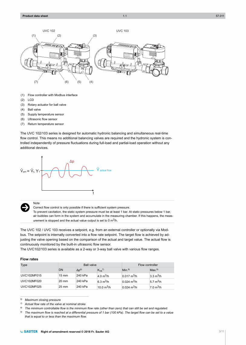
(1) Flow controller with Modbus interface(2) LCD(3) Rotary actuator for ball valve(4) Ball valve(5) Supply temperature sensor(6) Ultrasonic flow sensor(7) Return temperature sensor
The UVC 102/103 series is designed for automatic hydronic balancing and simultaneous real-timeflow control. This means no additional balancing valves are required and the hydronic system is con-trolled independently of pressure fluctuations during full-load and partial-load operation without anyadditional devices.
m actual flowmam = ms, 1Y
)p
t
)NoteCorrect flow control is only possible if there is sufficient system pressure.To prevent cavitation, the static system pressure must be at least 1 bar. At static pressures below 1 bar,air bubbles can form in the system and accumulate in the measuring chamber. If this happens, the meas-urement is stopped and the actual value output is set to 0 m3/h.
The UVC 102 / UVC 103 receives a setpoint, e.g. from an external controller or optionally via Mod-bus. The setpoint is internally converted into a flow rate setpoint. The target flow is achieved by ad-justing the valve opening based on the comparison of the actual and target value. The actual flow iscontinuously monitored by the built-in ultrasonic flow sensor.The UVC102/103 series is available as a 2-way or 3-way ball valve with various flow ranges.
Flow ratesType Ball valve Flow controller
DN Δp6) Kvs7) Min.8) Max.9)
UVC102MF015 15 mm 240 kPa 4.0 m3/h 0.017 m3/h 3.3 m3/hUVC102MF020 20 mm 240 kPa 6.3 m3/h 0.024 m3/h 5.7 m3/hUVC102MF025 25 mm 240 kPa 10.0 m3/h 0.024 m3/h 7.0 m3/h
6) Maximum closing pressure7) Actual flow rate of the valve at nominal stroke8) The minimum controllable flow is the minimum flow rate (other than zero) that can still be set and regulated.9) The maximum flow is reached at a differential pressure of 1 bar (100 kPa). The target flow can be set to a value
that is equal to or less than the maximum flow.
Product data sheet 1.1 57.011
Right of amendment reserved © 2018 Fr. Sauter AG 3/11
Type Ball valve Flow controllerDN Δp6) Kvs7) Min.8) Max.9)
UVC102MF032 32 mm 240 kPa 16.0 m3/h 0.042 m3/h 10.5 m3/hUVC102MF040 40 mm 240 kPa 25.0 m3/h 0.07 m3/h 15.0 m3/hUVC102MF050 50 mm 240 kPa 40.0 m3/h 0.07 m3/h 20.0 m3/hUVC103MF015 15 mm 240 kPa 4.0 m3/h 0.017 m3/h 3.3 m3/hUVC103MF020 20 mm 240 kPa 6.3 m3/h 0.024 m3/h 5.7 m3/hUVC103MF025 25 mm 240 kPa 10.0 m3/h 0.024 m3/h 7.0 m3/hUVC103MF032 32 mm 240 kPa 16.0 m3/h 0.042 m3/h 10.5 m3/hUVC103MF040 40 mm 240 kPa 25.0 m3/h 0.07 m3/h 15.0 m3/hUVC103MF050 50 mm 240 kPa 40.0 m3/h 0.07 m3/h 20.0 m3/h
Intended useThis product is only suitable for the purpose intended by the manufacturer, as described in the “De-scription of operation” section.All related product regulations must also be adhered to. Changing or converting the product is not ad-missible.
Improper useThe eValveco flow control system does not meet the conformity requirements of the Measuring Instru-ments Directive 2014/32/EU. The eValveco system cannot be used instead of a calibrated heat meterfor the purposes of energy billing.The system is not suitable for use in drinking water systems according to the directives 98/83/EC and2015/1787/EU.
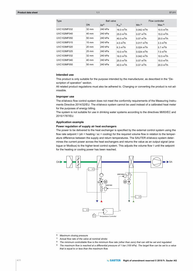
Application examplePower regulation of supply air heat exchangersThe power to be delivered to the heat exchanger is specified by the external control system using theflow rate setpoint m (sh = heating / sc = cooling) for the required volume flow in relation to the temper-ature difference between the supply and return temperatures. The SAUTER eValveco system deter-mines the current power across the heat exchangers and returns the value as an output signal (ana-logue or Modbus) to the higher-level control system. This adjusts the volume flow m until the setpointfor the heating or cooling power has been reached.
OA SA
A
B
AB
T
~T
T
~
yT
Temperature Controller
UVC102
UVC103
T
6) Maximum closing pressure7) Actual flow rate of the valve at nominal stroke8) The minimum controllable flow is the minimum flow rate (other than zero) that can still be set and regulated.9) The maximum flow is reached at a differential pressure of 1 bar (100 kPa). The target flow can be set to a value
that is equal to or less than the maximum flow.
Product data sheet 1.1 57.011
4/11 Right of amendment reserved © 2018 Fr. Sauter AG
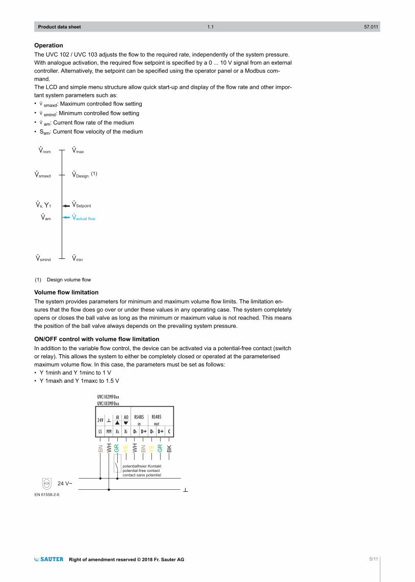
OperationThe UVC 102 / UVC 103 adjusts the flow to the required rate, independently of the system pressure.With analogue activation, the required flow setpoint is specified by a 0 ... 10 V signal from an externalcontroller. Alternatively, the setpoint can be specified using the operator panel or a Modbus com-mand.The LCD and simple menu structure allow quick start-up and display of the flow rate and other impor-tant system parameters such as:• m smaxd: Maximum controlled flow setting• m smind: Minimum controlled flow setting• m am: Current flow rate of the medium• Sam: Current flow velocity of the medium
mmax
mDesign
mSetpoint
mactual flow
mmin
mnom
msmaxd
ms, 1Y
mam
msmind
(1)
(1) Design volume flow
Volume flow limitationThe system provides parameters for minimum and maximum volume flow limits. The limitation en-sures that the flow does go over or under these values in any operating case. The system completelyopens or closes the ball valve as long as the minimum or maximum value is not reached. This meansthe position of the ball valve always depends on the prevailing system pressure.
ON/OFF control with volume flow limitationIn addition to the variable flow control, the device can be activated via a potential-free contact (switchor relay). This allows the system to either be completely closed or operated at the parameterisedmaximum volume flow. In this case, the parameters must be set as follows:• Y 1minh and Y 1minc to 1 V• Y 1maxh and Y 1maxc to 1.5 V
EN 61558-2-6
24 V~
potentialfreier Kontaktpotential-free contactcontact sans potentiel
24V
LS MM Xs
AI
Xi
AO
D- D+
UVC102MF0xx
UVC103MF0xx
D- D+
RS485
in
D- D+ C
RS485
out
D- D+ C
WH
BN
GR
YE
WH
BN
YE
GR
BK
Product data sheet 1.1 57.011
Right of amendment reserved © 2018 Fr. Sauter AG 5/11
Flush modeWhen commissioned for the first time, the UVC 102 / UVC 103 is in flush mode, with the ball valvefully opened. It exits flush mode as soon as the setpoint is above 8 V or when this mode is deactiva-ted using a Modbus command or the control panel.If a fault occurs in the power supply before flush mode is deactivated, flush mode remains active alsoafter the power returns.If there is a power failure after flush mode has been completed, flush mode is deactivated after thepower returns.
Temperature measurementThe UVC 102 and UVC 103 contain one Pt500 temperature sensor in the supply line and one in thereturn line. The measured temperatures can be read via Modbus or the LCD.The temperature sensor T1 is integrated in the flow meter in the UVC 102 and UVC 103. The temper-ature sensor T2 must be mounted on site. The temperature sensor is supplied with a free cable length of 2.0 m.
)NoteIn order to properly calculate the energy consumption, the temperature sensors must be correctly as-signed to the supply and return lines using the variable Treturn.
Energy monitoringThe UVC 102 / UVC 103 calculates the current thermal energy consumption and accumulates the to-tal energy consumption during operation. The current thermal energy consumption is stored in thevariable PWR (in watts).To measure the total energy consumption, the current consumptions are integrated over time. The en-ergy consumption10) is saved in a read-only variable every two hours:• EnerHeat (SysType = heating)• EnerCool (SysType = cooling)
It is not possible to reset the accumulated value.The values are stored in a non-volatile memory. If there is a power failure in the installation, the val-ues for the last two hours at most can be lost. The data memory is designed for a storage period of atleast 5 years. When the memory is full, the value is reset to zero. With typical usage, the value is readout yearly. A difference calculation is used to determine the energy consumption for the last time peri-od.
)NoteThe system always saves the energy consumption in the “EnerHeat” or “EnerCool” variable based on the“ClimStatus” value.
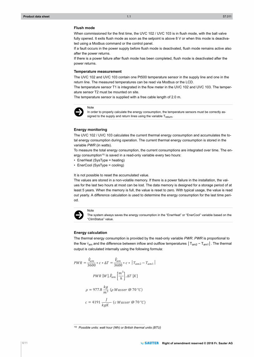
Energy calculationThe thermal energy consumption is provided by the read-only variable PWR. PWR is proportional tothe flow mam and the difference between inflow and outflow temperatures │Tam2 − Tam1│. The thermaloutput is calculated internally using the following formula:
=3600
=3600 2 1│
3
"[ ], , [ ]
3= 977.8
= 4191
( @ 70 ° )
( @ 70 ° )
10) Possible units: watt hour (Wh) or British thermal units (BTU)
Product data sheet 1.1 57.011
6/11 Right of amendment reserved © 2018 Fr. Sauter AG
)NoteIn the PWR variable, the value 0xFFF may be displayed under the following conditions:• Energy consumption outside the measured value• Tam1 > 95 °C or Tam2 > 95 °C (range exceeded)
• Tam2 is not connected and Text = 0
Error handlingSelf-testWhen it is switched on, the device performs a self-test and checks the program and data memory. Ifone of these checks fails, an error bit is set depending on the type of error. This can be read via Mod-bus.WarningIf the system is operated outside the valid temperature range, it cannot achieve its guaranteed accu-racy. This may result in irreparable damage to the product. For this reason, if the water temperature isoutside the permissible range, the warning bit “b0” is set to 1 and “Err” appears on the display. It isdeleted as soon as the temperature is back in the specified range.
)NoteIf the required setpoint is between the closed ball valve position and the smallest possible opening, thecontroller alternately opens and closes the ball valve. In this case, the mean volume flow corresponds tothe setpoint.
ErrorIn the event of a system error, the following information is provided:• b0: Error in CRC check during boot process.• b1: EEPROM area error while booting.• b2: Invalid variable: This bit is set when a variable outside the valid range is entered. It is reset as
soon as the variable is entered in the correct range.• b3: Conflict on changeover switching: This bit is set if Y1h and Y1c are both higher than their respec-
tive minimum values Y1minh and Y1minc.• b4 and b5: unused, reserved for future use
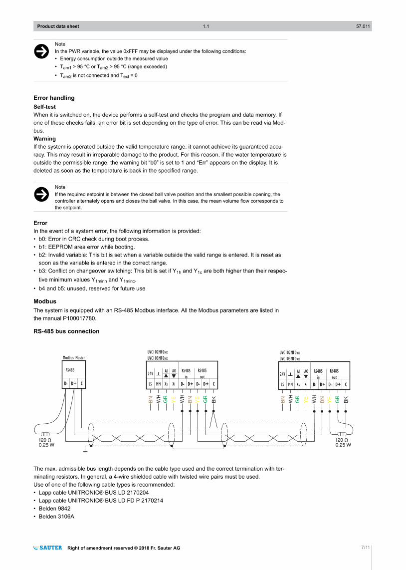
ModbusThe system is equipped with an RS-485 Modbus interface. All the Modbus parameters are listed inthe manual P100017780.
RS-485 bus connection
Modbus Master
D- D+ C
RS485
D- D+ C
24V
LS MM Xs
AI
Xi
AO
D- D+
UVC102MF0xx
UVC103MF0xx
D- D+
RS485
in
D- D+ C
RS485
out
D- D+ C
24V
LS MM Xs
AI
Xi
AO
D- D+
UVC102MF0xx
UVC103MF0xx
D- D+
RS485
in
D- D+ C
RS485
out
D- D+ C
0,25 W0,25 W
WH
BN
GR
YE
WH
BN
YE
GR
BK
WH
BN
GR
YE
WH
BN
YE
GR
BK
The max. admissible bus length depends on the cable type used and the correct termination with ter-minating resistors. In general, a 4-wire shielded cable with twisted wire pairs must be used.Use of one of the following cable types is recommended:• Lapp cable UNITRONIC® BUS LD 2170204• Lapp cable UNITRONIC® BUS LD FD P 2170214• Belden 9842• Belden 3106A
Product data sheet 1.1 57.011
Right of amendment reserved © 2018 Fr. Sauter AG 7/11
• Belden 3107A
Observe the correct polarity of all signals. The cable shield of the entire bus line must be connectedcontinuously, and connected to protective earth as directly as possible at one location. The shieldingis to be earthed in the plant as follows:• Shielding earthed at one end is suitable for protection from electrical interference (from overhead
power lines, static charges etc.)• Shielding earthed at both ends is suitable for protection from electromagnetic interference (from fre-
quency converters, electric motors, coils etc.)
)NoteFaulty wiring can result in damage to the device.All the devices in a network must be connected to the same power supply.
For Ethernet CAT-5 cables and J-Y(ST)Y cables, a bus length of up to 500 m is possible. The lengthof the bus line is limited by the following parameters:• Number of connected devices• Cross-section of cable used
In the case of RS-485 interfaces, the bus wiring must follow line topology. Star, tree or branch topolo-gies are not recommended. The devices do not have internal terminating resistors. Therefore, a ter-minating resistor of 120 Ω (0.25 W) must be connected at the start and end of the bus line, parallel tothe D+/D- data lines.
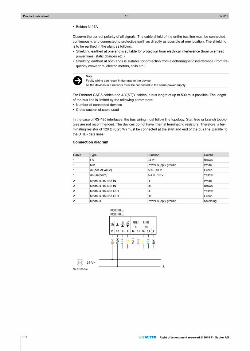
Connection diagram
Cable Type Function Colour1 LS 24 V~ Brown1 MM Power supply ground White1 Xi (actual value) AI 0...10 V Green1 Xs (setpoint) AO 0...10 V Yellow
2 Modbus RS-485 IN D- White2 Modbus RS-485 IN D+ Brown2 Modbus RS-485 OUT D- Yellow2 Modbus RS-485 OUT D+ Green2 Modbus Power supply ground Shielding
EN 61558-2-6
24 V~
24V
LS MM Xs
AI
Xi
AO
D- D+
UVC102MF0xx
UVC103MF0xx
D- D+
RS485
in
D- D+ C
RS485
out
D- D+ C
WH
BN
GR
YE
WH
BN
YE
GR
BK
Product data sheet 1.1 57.011
8/11 Right of amendment reserved © 2018 Fr. Sauter AG
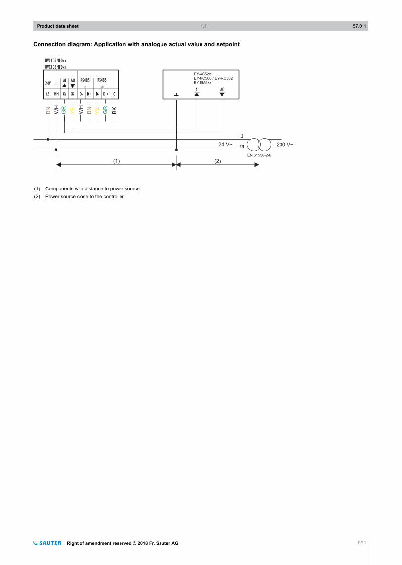
Connection diagram: Application with analogue actual value and setpoint
EN 61558-2-6
MM
AI AO
EY-AS52xEY-RC500 / EY-RC502EY-EM5xx24V
LS MM Xs
AI
Xi
AO
D- D+
UVC102MF0xx
UVC103MF0xx
D- D+
RS485
in
D- D+ C
RS485
out
D- D+ C
WH
BN
GR
YE
WH
BN
YE
GR
BK
LS
230 V~24 V~
(1) (2)
(1) Components with distance to power source(2) Power source close to the controller
Product data sheet 1.1 57.011
Right of amendment reserved © 2018 Fr. Sauter AG 9/11
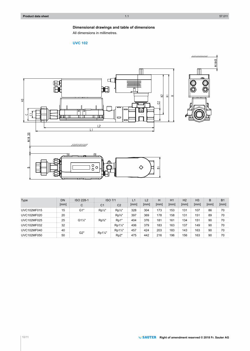
Dimensional drawings and table of dimensionsAll dimensions in millimetres.
UVC 102
Type DN [mm]
ISO 228-1 ISO 7/1 L1[mm]
L2[mm]
H[mm]
H1[mm]
H2[mm]
H3[mm]
B[mm]
B1[mm]C C1 C2
UVC102MF015 15 G1" Rp½" Rp½" 328 304 173 153 131 107 86 70UVC102MF020 20
G1¼" Rp¾"Rp¾" 397 369 178 158 131 151 89 70
UVC102MF025 25 Rp1" 404 376 181 161 134 151 90 70UVC102MF032 32 Rp1¼" 406 379 183 163 137 149 90 70UVC102MF040 40
G2" Rp1¼"Rp1½" 457 424 203 183 143 163 90 70
UVC102MF050 50 Rp2" 475 442 216 196 156 163 90 70
Product data sheet 1.1 57.011
10/11 Right of amendment reserved © 2018 Fr. Sauter AG
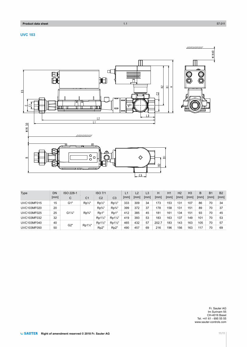
UVC 103
Type DN [mm]
ISO 228-1 ISO 7/1 L1[mm]
L2[mm]
L3[mm]
H[mm]
H1[mm]
H2[mm]
H3[mm]
B[mm]
B1[mm]
B2[mm]C C1 C2 C3
UVC103MF015 15 G1" Rp½" Rp½" Rp½" 333 309 34 173 153 131 107 86 70 34UVC103MF020 20
G1¼" Rp¾"Rp¾" Rp¾" 399 372 37 178 158 131 151 89 70 37
UVC103MF025 25 Rp1" Rp1" 412 385 45 181 161 134 151 93 70 45UVC103MF032 32 Rp1¼" Rp1¼" 419 393 53 183 163 137 149 101 70 53UVC103MF040 40
G2" Rp1¼"Rp1½" Rp1½" 465 432 57 202.7 183 143 163 105 70 57
UVC103MF050 50 Rp2" Rp2" 490 457 69 216 196 156 163 117 70 69
Product data sheet 1.1 57.011
Right of amendment reserved © 2018 Fr. Sauter AG 11/11
Fr. Sauter AGIm Surinam 55
CH-4016 BaselTel. +41 61 - 695 55 55
www.sauter-controls.com