Embed Size (px)
Citation preview
UvA-DARE is a service provided by the library of the University of Amsterdam (http://dare.uva.nl)
UvA-DARE (Digital Academic Repository)
Second coordination sphere effects in [FeFe]-Hydrogenase mimicsZaffaroni, R.
Link to publication
Citation for published version (APA):Zaffaroni, R. (2017). Second coordination sphere effects in [FeFe]-Hydrogenase mimics
General rightsIt is not permitted to download or to forward/distribute the text or part of it without the consent of the author(s) and/or copyright holder(s),other than for strictly personal, individual use, unless the work is under an open content license (like Creative Commons).
Disclaimer/Complaints regulationsIf you believe that digital publication of certain material infringes any of your rights or (privacy) interests, please let the Library know, statingyour reasons. In case of a legitimate complaint, the Library will make the material inaccessible and/or remove it from the website. Please Askthe Library: http://uba.uva.nl/en/contact, or a letter to: Library of the University of Amsterdam, Secretariat, Singel 425, 1012 WP Amsterdam,The Netherlands. You will be contacted as soon as possible.
Download date: 07 Feb 2019

1Introduction
~ 2 ~
Second coordination sphere effects
in [FeFe]-Hydrogenase mimics
The energy problem
Long before our ancestors, photosynthesis was already converting carbon dioxide into sug-ars, over time transformed into fossil fuels, paving the road for the evolution of life. Ever since humankind made its appearance, its growth and progress have been closely linked to the amount of energy available, either for nutrition or to perform work.1 For very long time the exclusive source of energy that our species could rely on has been that provided by photosyn-thesis. The first breakthrough in our evolution did not come until the human race managed to master fire; access to heat made possible the development of cooking, object crafting and expansion to previously inhospitable cold lands. A second big step forward happened during the Neolithic with settlement and most importantly with the birth of agriculture. Although agriculture gave access to virtually limitless food, the growth of society was still hindered by lack of energy to perform work but only until the third and most recent breakthrough; the Industrial Revolution.
Industrial Revolution brought great prosperity and allowed for the vast growth of society as we know it today. Thanks to the exploitation of fossil fuels, energy to perform work has no longer been a limiting factor. Indeed, due to the large availability of food and energy in our current society, it has been estimated that the annual growth rate for the world population will constantly increase by about 2.3%.2 To keep up with this impressive trend, the energy demand is surely expected to follow a similar exponential increase. Since the beginning of the Industrial Revolution, the ever-growing energy demand has been satisfied by burning fossil fuels, thus releasing the energy Nature stored over billions of years. Unfortunately this practice not only provides the energy we crave to sustain our society, but it comes with the consequence of releasing into the atmosphere carbon dioxide. Only in recent years we are concretely realizing that this is a matter of major concern.3 In fact, because carbon dioxide is a strong greenhouse gas and its level is constantly rising since the beginning of the Industrial Revolution, it contributes to large extent to the climate change processes that we are re-cently observing. With a current annual energy consumption rate around 13.5 TW, expected to double by 2050, it is now evident that the fossil fuels oriented society started roughly 250 years ago is not a viable option; thus the urgency for sustainable and carbon neutral energy sources.4
Among the renewable options, solar energy is by far the most abundant and cheapest form of energy available. As ballpark figure, the amount of energy reaching the earth’s surface from the sun every single hour could in fact be sufficient to cover the annual world energy demand.5 The technology needed to convert the solar radiation into usable electricity, photo-voltaics, is mature, accessible and already widely distributed.6,7 Its exceptional annual growth has been estimated around 20% for the last three years; following this trend, it is estimated
1
~ 3 ~
Introduction
that between 50 and 90% of the electricity demand will be actually provided by photovoltaic installations by mid-century.8 Although photovoltaics are a great solution to provide cheap energy, one major issue is the solar radiation intermittency which clearly evidences the de-pendence of our society from fossil fuels during dark hours.9 The origin of such problem could be boiled down to technological incapability to efficiently store and transport elec-tricity over long distances. Regarding this aspect, considerable efforts aimed at the develop-ment of batteries are ongoing and some progresses in the field have already been made e.g. redox flow batteries.10 In addition, electricity only accounts for roughly 20% of the world energy demand, the remaining being fossil fuels in the form of oil (32%), coal (30%) and gas (21%), underlining the need for a different energy carrier.4 Among the options proposed, the most interesting energy carrier substitutes are identified as hydrogen, ammonia, formic acid, methanol or methane.11
Hydrogen seems the most straightforward choice, because it can be produced by electrolysis of water, for example by coupling photovoltaic panels to electrolysis devices.12 In this way, the electricity generated can be immediately converted and stored into chemical bonds. Although this is a proven technology, several problems are associated with this solution. The materials needed for the construction of electrolyzers are typically scarce and thus expensive metals and hence not attractive for large scale application. As a second issue, energy conversion - e.g. from solar radiation to electricity or from electricity to chemical bonds - is a process that comes with energy losses. It becomes thus evident that processes with less conversion steps can account, in principle, for higher efficiency. To this end, great effort is being spent in the development of direct conversion processes able to directly use sunlight to construct new bonds yielding sustainable energy carriers to be used by our society. A notable example of di-rect solar to chemical energy storage is provided by the natural photosynthetic process that has been accompanying us throughout our progress. Although nowadays it might seem we are no longer dependent on photosynthesis for our energy supply, we are finding ourselves looking back at this amazing machinery that has been ever since converting sunlight into chemical bonds and trying to glean and reproduce its secrets in what is imaginatively known as ‘artificial photosynthesis’.
Natural photosynthesis
It is estimated that photosynthesis has the capability of storing about 100 TW of solar radia-tion into chemical bonds during the course of a single year; several times more than our en-ergy consumption, furthermore with a solar to chemical bond (biomass) efficiency of about only 0.1%.5 In order to sustain its metabolism, Nature has evolved a very complex machinery
~ 4 ~
Second coordination sphere effects
in [FeFe]-Hydrogenase mimics
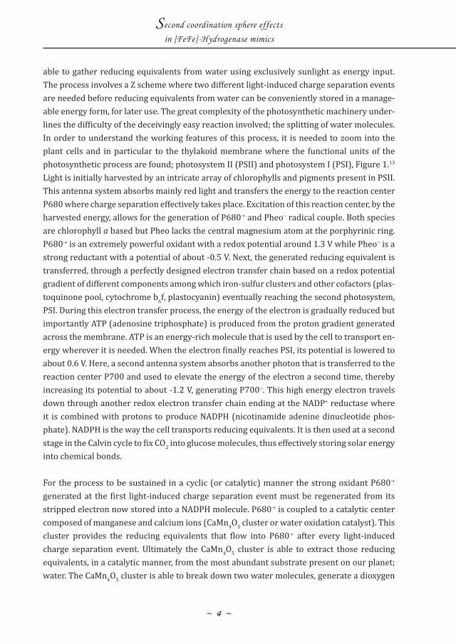
able to gather reducing equivalents from water using exclusively sunlight as energy input. The process involves a Z scheme where two different light-induced charge separation events are needed before reducing equivalents from water can be conveniently stored in a manage-able energy form, for later use. The great complexity of the photosynthetic machinery under-lines the difficulty of the deceivingly easy reaction involved; the splitting of water molecules. In order to understand the working features of this process, it is needed to zoom into the plant cells and in particular to the thylakoid membrane where the functional units of the photosynthetic process are found; photosystem II (PSII) and photosystem I (PSI), Figure 1.13 Light is initially harvested by an intricate array of chlorophylls and pigments present in PSII. This antenna system absorbs mainly red light and transfers the energy to the reaction center P680 where charge separation effectively takes place. Excitation of this reaction center, by the harvested energy, allows for the generation of P680∙+ and Pheo∙- radical couple. Both species are chlorophyll a based but Pheo lacks the central magnesium atom at the porphyrinic ring. P680∙+ is an extremely powerful oxidant with a redox potential around 1.3 V while Pheo∙- is a strong reductant with a potential of about -0.5 V. Next, the generated reducing equivalent is transferred, through a perfectly designed electron transfer chain based on a redox potential gradient of different components among which iron-sulfur clusters and other cofactors (plas-toquinone pool, cytochrome b6f, plastocyanin) eventually reaching the second photosystem, PSI. During this electron transfer process, the energy of the electron is gradually reduced but importantly ATP (adenosine triphosphate) is produced from the proton gradient generated across the membrane. ATP is an energy-rich molecule that is used by the cell to transport en-ergy wherever it is needed. When the electron finally reaches PSI, its potential is lowered to about 0.6 V. Here, a second antenna system absorbs another photon that is transferred to the reaction center P700 and used to elevate the energy of the electron a second time, thereby increasing its potential to about -1.2 V, generating P700∙-. This high energy electron travels down through another redox electron transfer chain ending at the NADP+ reductase where it is combined with protons to produce NADPH (nicotinamide adenine dinucleotide phos-phate). NADPH is the way the cell transports reducing equivalents. It is then used at a second stage in the Calvin cycle to fix CO2 into glucose molecules, thus effectively storing solar energy into chemical bonds.
For the process to be sustained in a cyclic (or catalytic) manner the strong oxidant P680∙+ generated at the first light-induced charge separation event must be regenerated from its stripped electron now stored into a NADPH molecule. P680∙+ is coupled to a catalytic center composed of manganese and calcium ions (CaMn4O5 cluster or water oxidation catalyst). This cluster provides the reducing equivalents that flow into P680∙+ after every light-induced charge separation event. Ultimately the CaMn4O5 cluster is able to extract those reducing equivalents, in a catalytic manner, from the most abundant substrate present on our planet; water. The CaMn4O5 cluster is able to break down two water molecules, generate a dioxygen
1
~ 5 ~
Introduction
molecule as byproduct and provide electrons to P680∙+, thereby closing the cycle. The water splitting reaction operated by this machinery is the most important reaction known. It is critical to realize that it established the basis of life as we know it today, it has been powering the planet all along and now providing us with clear insights to face our current energy prob-lem.
Hydrogenases
Nature provides detailed blueprints to achieve solar energy storage but the photosynthetic process finally affords carbohydrates, which might not be the most suitable energy carrier for our society. Nevertheless, Nature provides also other relevant lessons. Already back in 1892 it was observed that some microorganisms could sustain their metabolism by extracting re-ducing equivalents from hydrogen.14 It then took several years before the term ‘Hydrogenase’ was coined to refer to an enzyme able to catalyze the reversible interconversion between protons and dihydrogen.15,16 Although it has long been known that hydrogenase enzymes contain iron centers, only in the ‘90s X-ray crystal structures determination gave more pre-cise insights regarding the active site of the enzymes, clearly revealing their organometallic nature, based on iron-sulfur clusters.17-20 Three different types of hydrogenase are known today. All are metalloenzymes containing either iron-iron, nickel-iron or a mono-iron core. Although the three types of enzymes catalyze the reaction in both directions, the di-iron hy-drogenases are without doubt the fastest enzymes for proton reduction, the nickel-iron ones are more dedicated to hydrogen oxidation and the iron hydrogenases are specialized at cata-lyzing the reversible reduction of methenyltetrahydromethanopterin (methenyl-H4MPT+) to methylene-H4MPT by hydride transfer, thereby activating hydrogen. Because such metallo-
Figure 1. Schematic representation of the thylakoid membrane evidencing the essential compo-nents for the light-induced water oxidation process of natural photosynthesis. Highlighted in red the Z scheme strategy to sequentially elevate the energy of reducing equivalents.
~ 6 ~
Second coordination sphere effects
in [FeFe]-Hydrogenase mimics
enzymes can produce hydrogen at comparable rates as platinum, which is the best catalyst known for hydrogen evolution, and with similar driving force while being based on cheap and earth abundant elements, these systems are highly interesting in view of possible ap-plications.21
Concerning the iron-iron hydrogenases, several years of detailed spectroscopic inquisition were needed to fully elucidate the structure of the organometallic active site, now referred to as the H-cluster, which was found to contain six iron atoms and seven sulfur atoms. The H-cluster can be subdivided into a di-iron center covalently connected, through a cysteine ligand, to a cubane-like Fe4S4 structure. Looking at the entire crystal structure of the enzyme, the Fe4S4 cluster is found to be at the end of an electron transfer chain constituted by several other iron-sulfur clusters. This feature evidences the importance of electron transfer during the catalytic process. Moving back to the di-iron core, several interesting features are noted. The two metallic ions (referred as distal and proximal iron, with respect to the Fe4S4 cluster) are bridged by a dithiolate ligand. Only recently, the full structure of this bridge has been clar-ified and found to be consistent with a S-CH2-NH-CH2-S fragment.22 This bridge is usually re-ferred to as the azadithiolate (adt) cofactor,* where the central nitrogen atom sits just above a vacant coordination site at the distal iron. This vacant position is believed to be the place where the reversible conversion of protons into hydrogen takes place. The basic nitrogen is believed to mediate the shuttling of protons from a nearby cysteine residue, found to be just at the end of a proton transfer channel, and the iron center. To complete the coordination sphere of the iron ions, three CO ligands, one of which semi-bridges the two irons, and two CN- ligands are present. Both CO and CN- are very unusual biological ligands. Interestingly, when the enzyme is exposed to such compounds, its catalytic activity is inhibited.
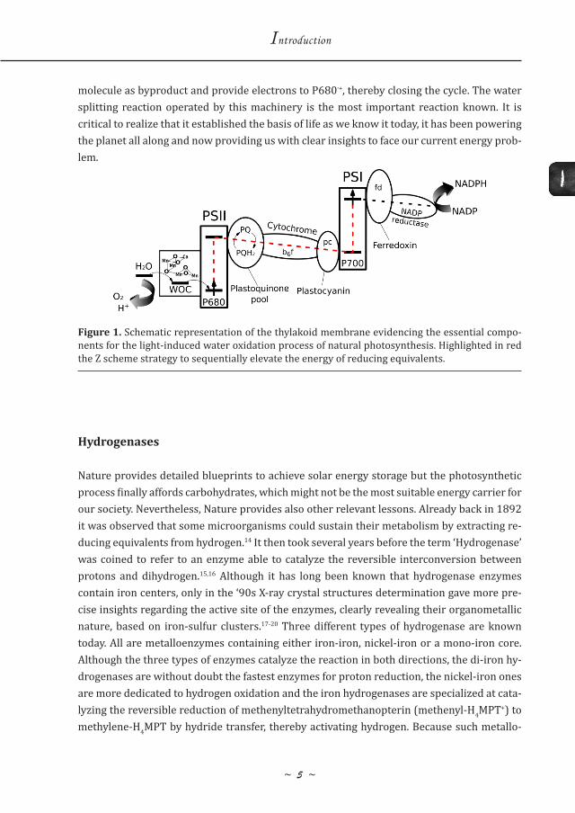
Figure 2 shows a picture of the crystal structure of the iron-iron hydrogenase from Clostridi-um pasteurianum, illustrating the structure of the H-cluster and its hydrogen bonding with nearby residues. The H-cluster is embedded in a hydrophobic pocket surrounded by a dense protein matrix. Several highly conserved amino acid residues are found to hydrogen bond to the organometallic cluster keeping it in place, forcing it to adopt the so-called rotated struc-ture with a bridging carbonyl and an apical vacant site at the distal iron, where proton reduc-tion is believed to take place. Most of the hydrogen bonded residues have been shown to be essential for the catalytic activity of the enzyme while others, although not essential, are im-portant to achieve high rates.23 The very rigid structure of H-cluster and the vacant site at the
* Although literature refers to the azadithiolate bridge as being a cofactor and it has been shown to be essential for the enzymatic activity, we note that this might not be the proper classification, as the adt fragment is inherently part of the larger structure of the di-iron core. Nevertheless, throughout this thesis the adt bridge of the natural di-iron hydrogenase enzyme will be referred to as cofactor.
1
~ 7 ~
Introduction
distal iron suggest that terminal hydrides are involved in the mechanism, although their spectroscopic evidence remains elusive so far. The Fe4S4 cluster connected to the proximal iron and the azadithiolate cofactor are believed to work in concert to deliver reducing equiv-alents from one side and proton substrates from the other. To justify the high catalytic rates, proton coupled electron transfer (PCET) steps have long been speculatively invoked. Al-though definitive proofs are still lacking, new observations point to the involvement of PCET steps in the catalytic cycle.24
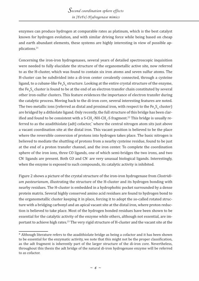
The catalytic mechanism for the H-cluster has been under constant debate.25,26 According to most recent findings, it is suggested to feature six different states.24 For the hy-drogen evolution path, the cycle starts with the Hred state which undergoes a pro-ton coupled electronic rearrangement to generate HredH+ where one electron is transferred from the Fe4S4 cluster to the distal iron while the proton is believed to be located at the adt bridge. An electron transfer to the Fe4S4 cluster generates HsredH+ which undergoes a second proton-ation to generate HhydH+. A second elec-tronic rearrangement transferring one electron from the Fe4S4 cluster into the di-iron core, coupled to the formation of
Figure 2. Crystal structure of the iron-iron hydrogenase from Clostridium pasteurianum, evidenc-ing the structure of the H-cluster and its hydrogen bonding with the nearby residues that are es-sential for the activity of the enzyme.23 Figure taken from ref. 23.
Figure 3. Proposed catalytic cycle for the iron-iron hydrogenases. Figure taken from ref. 24.
~ 8 ~
Second coordination sphere effects
in [FeFe]-Hydrogenase mimics
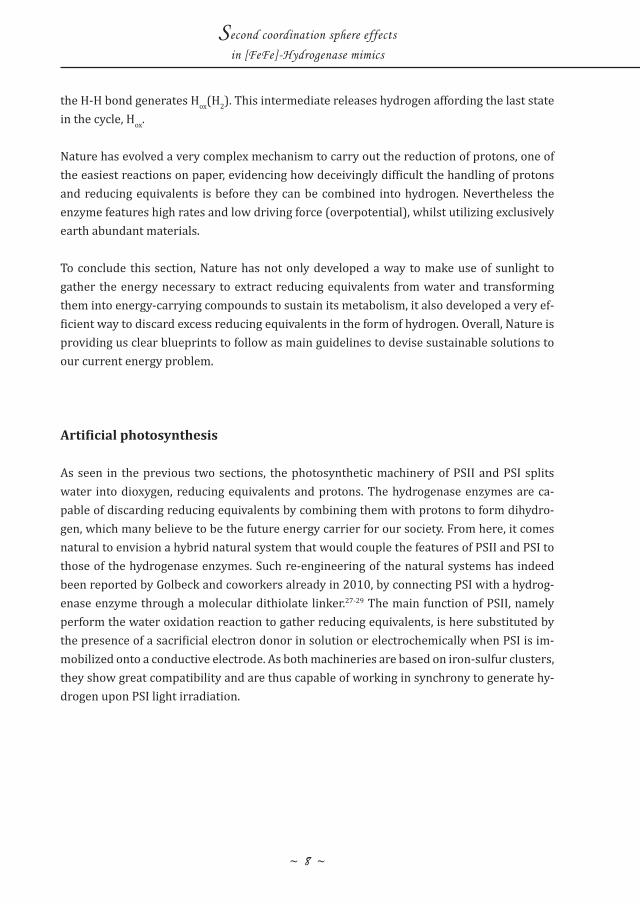
the H-H bond generates Hox(H2). This intermediate releases hydrogen affording the last state in the cycle, Hox.
Nature has evolved a very complex mechanism to carry out the reduction of protons, one of the easiest reactions on paper, evidencing how deceivingly difficult the handling of protons and reducing equivalents is before they can be combined into hydrogen. Nevertheless the enzyme features high rates and low driving force (overpotential), whilst utilizing exclusively earth abundant materials.
To conclude this section, Nature has not only developed a way to make use of sunlight to gather the energy necessary to extract reducing equivalents from water and transforming them into energy-carrying compounds to sustain its metabolism, it also developed a very ef-ficient way to discard excess reducing equivalents in the form of hydrogen. Overall, Nature is providing us clear blueprints to follow as main guidelines to devise sustainable solutions to our current energy problem.
Artificial photosynthesis
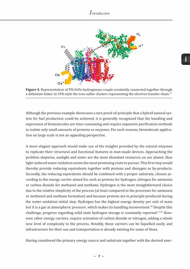
As seen in the previous two sections, the photosynthetic machinery of PSII and PSI splits water into dioxygen, reducing equivalents and protons. The hydrogenase enzymes are ca-pable of discarding reducing equivalents by combining them with protons to form dihydro-gen, which many believe to be the future energy carrier for our society. From here, it comes natural to envision a hybrid natural system that would couple the features of PSII and PSI to those of the hydrogenase enzymes. Such re-engineering of the natural systems has indeed been reported by Golbeck and coworkers already in 2010, by connecting PSI with a hydrog-enase enzyme through a molecular dithiolate linker.27-29 The main function of PSII, namely perform the water oxidation reaction to gather reducing equivalents, is here substituted by the presence of a sacrificial electron donor in solution or electrochemically when PSI is im-mobilized onto a conductive electrode. As both machineries are based on iron-sulfur clusters, they show great compatibility and are thus capable of working in synchrony to generate hy-drogen upon PSI light irradiation.
1
~ 9 ~
Introduction
Although the previous example showcases a nice proof-of-principle that a hybrid natural sys-tem for fuel production could be achieved, it is generally recognized that the handling and expression of biomolecules are time-consuming and require expensive purification methods to isolate only small amounts of proteins or enzymes. For such reasons, biomolecule applica-tion on large scale is not an appealing perspective.
A more elegant approach would make use of the insights provided by the natural enzymes to replicate their structural and functional features in man-made devices. Approaching the problem stepwise, sunlight and water are the most abundant resources on our planet, thus light-induced water oxidation seems the most promising route to pursue. This first step would thereby provide reducing equivalents together with protons and dioxygen as by-products. Secondly, the reducing equivalents should be combined with a proper substrate, chosen ac-cording to the energy carrier aimed for, such as protons for hydrogen, nitrogen for ammonia or carbon dioxide for methanol and methane. Hydrogen is the most straightforward choice due to the relative simplicity of the process (at least compared to the processes for ammonia or methanol and methane formation) and because protons are in principle produced during the water oxidation initial step. Hydrogen has the highest energy density per unit of mass but it is a gas at atmospheric pressure, which makes its handling inconvenient.30 Despite this challenge, progress regarding solid state hydrogen storage is constantly reported.31,32 How-ever, other energy carriers, require activation of carbon dioxide or nitrogen, adding a whole new level of complexity to the process. Notably, these carriers can be liquefied easily and infrastructure for their use and transportation is already existing for some of them.
Having considered the primary energy source and substrate together with the desired ener-
Figure 4. Representation of PSI-FeFe-hydrogenase couple covalently connected together through a dithiolate linker. In CPK-style the iron-sulfur clusters representing the electron transfer chain.27
~ 10 ~
Second coordination sphere effects
in [FeFe]-Hydrogenase mimics
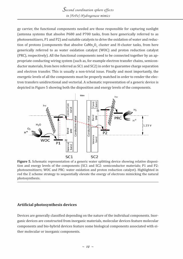
gy carrier, the functional components needed are those responsible for capturing sunlight (antenna systems that absolve P680 and P700 tasks, from here generically referred to as photosensitizers, P1 and P2) and suitable catalysts to drive the oxidation of water and reduc-tion of protons (components that absolve CaMn4O5 cluster and H-cluster tasks, from here generically referred to as water oxidation catalyst (WOC) and proton reduction catalyst (PRC), respectively). All the functional components need to be connected together by an ap-propriate conducting wiring system (such as, for example electron transfer chains, semicon-ductor materials, from here referred as SC1 and SC2) in order to guarantee charge separation and electron transfer. This is usually a non-trivial issue. Finally and most importantly, the energetic levels of all the components must be properly matched in order to render the elec-tron transfers unidirectional and vectorial. A schematic representation of a generic device is depicted in Figure 5 showing both the disposition and energy levels of the components.
Artificial photosynthesis devices
Devices are generally classified depending on the nature of the individual components. Inor-ganic devices are constructed from inorganic materials, molecular devices feature molecular components and bio-hybrid devices feature some biological components associated with ei-ther molecular or inorganic components.
Figure 5. Schematic representation of a generic water splitting device showing relative disposi-tion and energy levels of the components (SC1 and SC2: semiconductor materials; P1 and P2: photosensitizers; WOC and PRC: water oxidation and proton reduction catalyst). Highlighted in red the Z scheme strategy to sequentially elevate the energy of electrons mimicking the natural photosynthesis.
1
~ 1 1 ~
Introduction
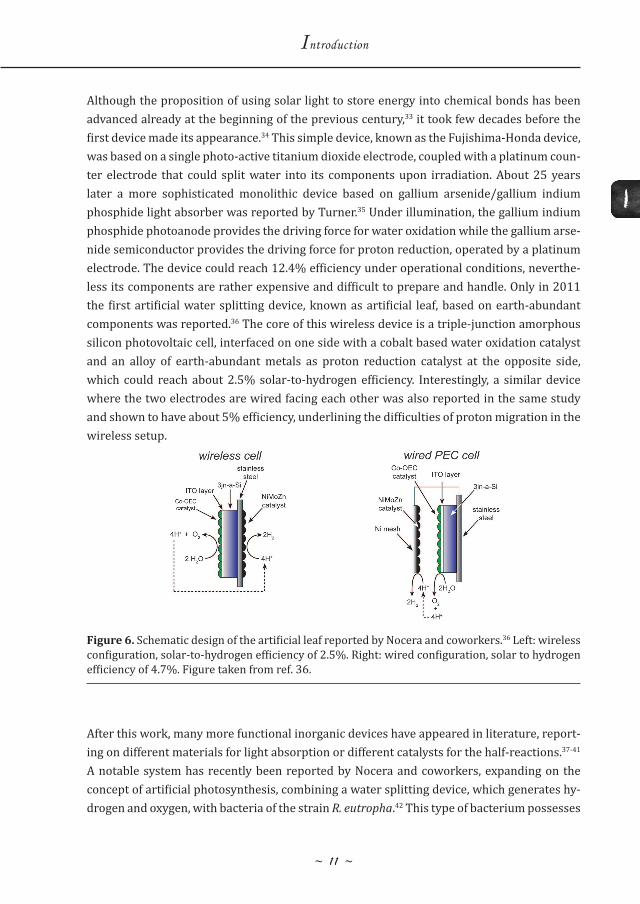
Although the proposition of using solar light to store energy into chemical bonds has been advanced already at the beginning of the previous century,33 it took few decades before the first device made its appearance.34 This simple device, known as the Fujishima-Honda device, was based on a single photo-active titanium dioxide electrode, coupled with a platinum coun-ter electrode that could split water into its components upon irradiation. About 25 years later a more sophisticated monolithic device based on gallium arsenide/gallium indium phosphide light absorber was reported by Turner.35 Under illumination, the gallium indium phosphide photoanode provides the driving force for water oxidation while the gallium arse-nide semiconductor provides the driving force for proton reduction, operated by a platinum electrode. The device could reach 12.4% efficiency under operational conditions, neverthe-less its components are rather expensive and difficult to prepare and handle. Only in 2011 the first artificial water splitting device, known as artificial leaf, based on earth-abundant components was reported.36 The core of this wireless device is a triple-junction amorphous silicon photovoltaic cell, interfaced on one side with a cobalt based water oxidation catalyst and an alloy of earth-abundant metals as proton reduction catalyst at the opposite side, which could reach about 2.5% solar-to-hydrogen efficiency. Interestingly, a similar device where the two electrodes are wired facing each other was also reported in the same study and shown to have about 5% efficiency, underlining the difficulties of proton migration in the wireless setup.
After this work, many more functional inorganic devices have appeared in literature, report-ing on different materials for light absorption or different catalysts for the half-reactions.37-41 A notable system has recently been reported by Nocera and coworkers, expanding on the concept of artificial photosynthesis, combining a water splitting device, which generates hy-drogen and oxygen, with bacteria of the strain R. eutropha.42 This type of bacterium possesses
Figure 6. Schematic design of the artificial leaf reported by Nocera and coworkers.36 Left: wireless configuration, solar-to-hydrogen efficiency of 2.5%. Right: wired configuration, solar to hydrogen efficiency of 4.7%. Figure taken from ref. 36.
~ 12 ~
Second coordination sphere effects
in [FeFe]-Hydrogenase mimics
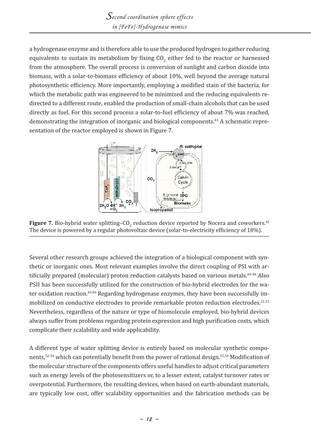
a hydrogenase enzyme and is therefore able to use the produced hydrogen to gather reducing equivalents to sustain its metabolism by fixing CO2 either fed to the reactor or harnessed from the atmosphere. The overall process is conversion of sunlight and carbon dioxide into biomass, with a solar-to-biomass efficiency of about 10%, well beyond the average natural photosynthetic efficiency. More importantly, employing a modified stain of the bacteria, for which the metabolic path was engineered to be minimized and the reducing equivalents re-directed to a different route, enabled the production of small-chain alcohols that can be used directly as fuel. For this second process a solar-to-fuel efficiency of about 7% was reached, demonstrating the integration of inorganic and biological components.43 A schematic repre-sentation of the reactor employed is shown in Figure 7.
Several other research groups achieved the integration of a biological component with syn-thetic or inorganic ones. Most relevant examples involve the direct coupling of PSI with ar-tificially prepared (molecular) proton reduction catalysts based on various metals.44-48 Also PSII has been successfully utilized for the construction of bio-hybrid electrodes for the wa-ter oxidation reaction.49,50 Regarding hydrogenase enzymes, they have been successfully im-mobilized on conductive electrodes to provide remarkable proton reduction electrodes.21,51 Nevertheless, regardless of the nature or type of biomolecule employed, bio-hybrid devices always suffer from problems regarding protein expression and high purification costs, which complicate their scalability and wide applicability.
A different type of water splitting device is entirely based on molecular synthetic compo-nents,52-54 which can potentially benefit from the power of rational design.55,56 Modification of the molecular structure of the components offers useful handles to adjust critical parameters such as energy levels of the photosensitizers or, to a lesser extent, catalyst turnover rates or overpotential. Furthermore, the resulting devices, when based on earth-abundant materials, are typically low cost, offer scalability opportunities and the fabrication methods can be
Figure 7. Bio-hybrid water splitting–CO2 reduction device reported by Nocera and coworkers.42 The device is powered by a regular photovoltaic device (solar-to-electricity efficiency of 18%).
1
~ 13 ~
Introduction
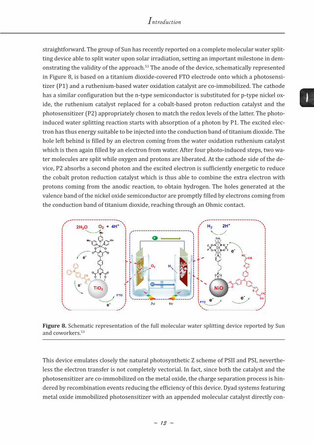
straightforward. The group of Sun has recently reported on a complete molecular water split-ting device able to split water upon solar irradiation, setting an important milestone in dem-onstrating the validity of the approach.53 The anode of the device, schematically represented in Figure 8, is based on a titanium dioxide-covered FTO electrode onto which a photosensi-tizer (P1) and a ruthenium-based water oxidation catalyst are co-immobilized. The cathode has a similar configuration but the n-type semiconductor is substituted for p-type nickel ox-ide, the ruthenium catalyst replaced for a cobalt-based proton reduction catalyst and the photosensitizer (P2) appropriately chosen to match the redox levels of the latter. The photo-induced water splitting reaction starts with absorption of a photon by P1. The excited elec-tron has thus energy suitable to be injected into the conduction band of titanium dioxide. The hole left behind is filled by an electron coming from the water oxidation ruthenium catalyst which is then again filled by an electron from water. After four photo-induced steps, two wa-ter molecules are split while oxygen and protons are liberated. At the cathode side of the de-vice, P2 absorbs a second photon and the excited electron is sufficiently energetic to reduce the cobalt proton reduction catalyst which is thus able to combine the extra electron with protons coming from the anodic reaction, to obtain hydrogen. The holes generated at the valence band of the nickel oxide semiconductor are promptly filled by electrons coming from the conduction band of titanium dioxide, reaching through an Ohmic contact.
This device emulates closely the natural photosynthetic Z scheme of PSII and PSI, neverthe-less the electron transfer is not completely vectorial. In fact, since both the catalyst and the photosensitizer are co-immobilized on the metal oxide, the charge separation process is hin-dered by recombination events reducing the efficiency of this device. Dyad systems featuring metal oxide immobilized photosensitizer with an appended molecular catalyst directly con-
Figure 8. Schematic representation of the full molecular water splitting device reported by Sun and coworkers.53
~ 1 4 ~
Second coordination sphere effects
in [FeFe]-Hydrogenase mimics
nected to it are believed to minimize recombination processes since they enforce vectorial electron transfer paths. In recent years more and more dyad systems have appeared in litera-ture both for water oxidation57-61 and proton reduction62-65 but most often such systems are studied in homogeneous solutions, in the presence of sacrificial electron donors or acceptors. Such studies have so far provided useful insights regarding the validity of the approach but unfortunately, their immobilization on metal oxides remains problematic due to synthetic challenges. Nevertheless the first systems to provide useful insights for future developments are now appearing.66-68
Core of the molecular devices are the water oxidation and proton reduction catalysts. As the rest of the thesis will focus on synthetic models of the di-iron hydrogenases as proton re-duction catalysts, general properties that a good catalyst should feature are next presented, before a brief overview regarding the configuration of typical molecular water oxidation and proton reduction catalysts is presented. Finally an extended overview regarding synthetic models of the iron-iron hydrogenases, focusing particularly on the efforts made at modeling the key features of the natural enzyme, is presented.
Molecular catalysts
Typically, before a molecular water splitting device is assembled, the components are studied individually, generally in homogeneous solution, to gain information related to the energy levels of the photosensitizer and other critical catalyst parameters. Great attention is devoted to the development of appropriate catalysts to fulfill specific requirements concerning over-potential, catalytic turnover rates and stability.
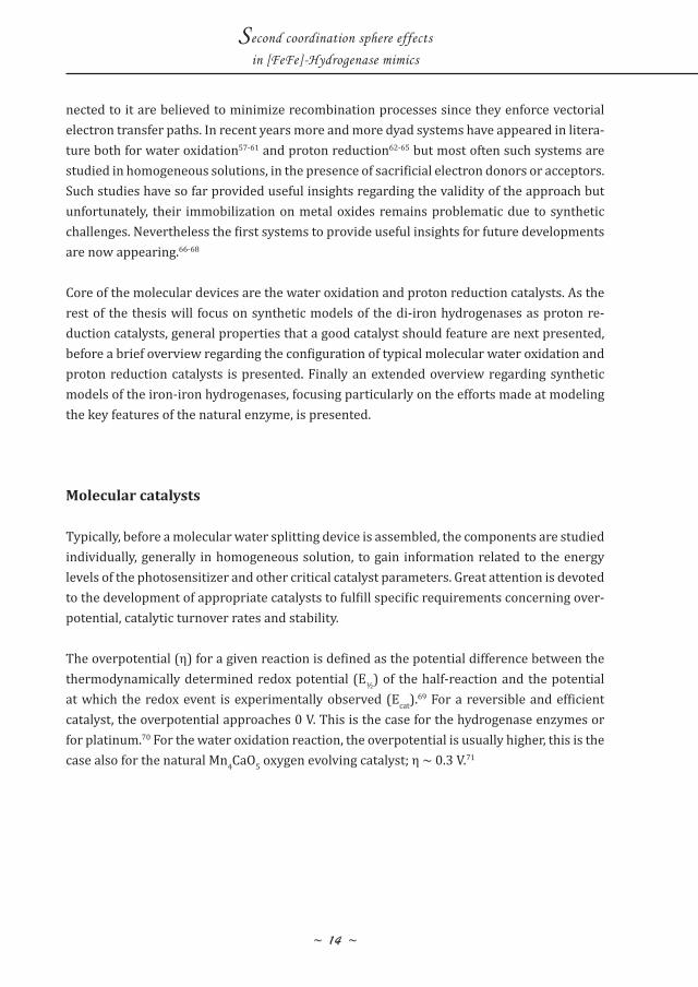
The overpotential (η) for a given reaction is defined as the potential difference between the thermodynamically determined redox potential (E½) of the half-reaction and the potential at which the redox event is experimentally observed (Ecat).69 For a reversible and efficient catalyst, the overpotential approaches 0 V. This is the case for the hydrogenase enzymes or for platinum.70 For the water oxidation reaction, the overpotential is usually higher, this is the case also for the natural Mn4CaO5 oxygen evolving catalyst; η ~ 0.3 V.71
1
~ 1 5 ~
Introduction
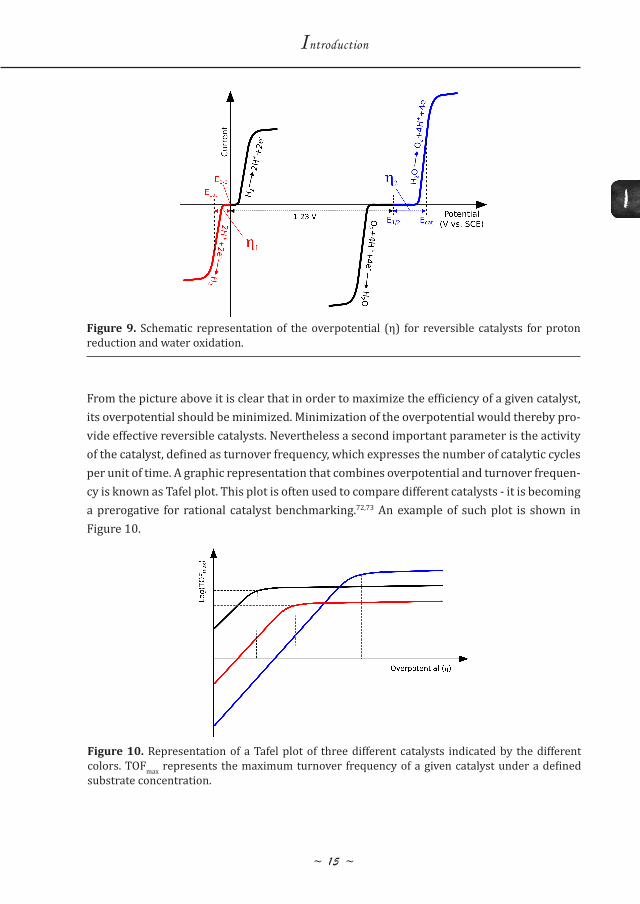
From the picture above it is clear that in order to maximize the efficiency of a given catalyst, its overpotential should be minimized. Minimization of the overpotential would thereby pro-vide effective reversible catalysts. Nevertheless a second important parameter is the activity of the catalyst, defined as turnover frequency, which expresses the number of catalytic cycles per unit of time. A graphic representation that combines overpotential and turnover frequen-cy is known as Tafel plot. This plot is often used to compare different catalysts - it is becoming a prerogative for rational catalyst benchmarking.72,73 An example of such plot is shown in Figure 10.
Figure 9. Schematic representation of the overpotential (η) for reversible catalysts for proton reduction and water oxidation.
Figure 10. Representation of a Tafel plot of three different catalysts indicated by the different colors. TOFmax represents the maximum turnover frequency of a given catalyst under a defined substrate concentration.
~ 1 6 ~
Second coordination sphere effects
in [FeFe]-Hydrogenase mimics
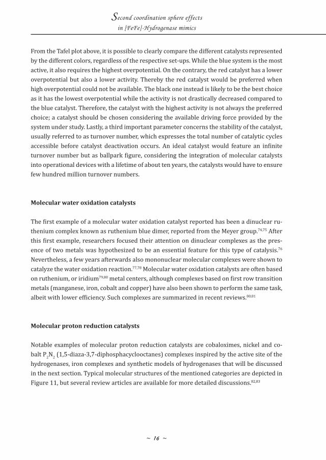
From the Tafel plot above, it is possible to clearly compare the different catalysts represented by the different colors, regardless of the respective set-ups. While the blue system is the most active, it also requires the highest overpotential. On the contrary, the red catalyst has a lower overpotential but also a lower activity. Thereby the red catalyst would be preferred when high overpotential could not be available. The black one instead is likely to be the best choice as it has the lowest overpotential while the activity is not drastically decreased compared to the blue catalyst. Therefore, the catalyst with the highest activity is not always the preferred choice; a catalyst should be chosen considering the available driving force provided by the system under study. Lastly, a third important parameter concerns the stability of the catalyst, usually referred to as turnover number, which expresses the total number of catalytic cycles accessible before catalyst deactivation occurs. An ideal catalyst would feature an infinite turnover number but as ballpark figure, considering the integration of molecular catalysts into operational devices with a lifetime of about ten years, the catalysts would have to ensure few hundred million turnover numbers.
Molecular water oxidation catalysts
The first example of a molecular water oxidation catalyst reported has been a dinuclear ru-thenium complex known as ruthenium blue dimer, reported from the Meyer group.74,75 After this first example, researchers focused their attention on dinuclear complexes as the pres-ence of two metals was hypothesized to be an essential feature for this type of catalysis.76 Nevertheless, a few years afterwards also mononuclear molecular complexes were shown to catalyze the water oxidation reaction.77,78 Molecular water oxidation catalysts are often based on ruthenium, or iridium79,80 metal centers, although complexes based on first row transition metals (manganese, iron, cobalt and copper) have also been shown to perform the same task, albeit with lower efficiency. Such complexes are summarized in recent reviews.80,81
Molecular proton reduction catalysts
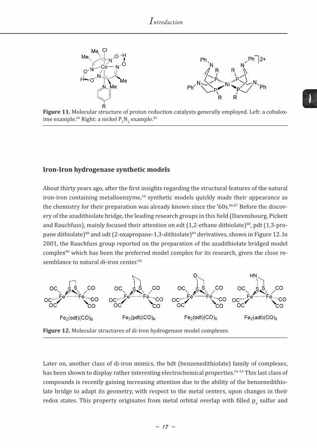
Notable examples of molecular proton reduction catalysts are cobaloximes, nickel and co-balt P2N2 (1,5-diaza-3,7-diphosphacyclooctanes) complexes inspired by the active site of the hydrogenases, iron complexes and synthetic models of hydrogenases that will be discussed in the next section. Typical molecular structures of the mentioned categories are depicted in Figure 11, but several review articles are available for more detailed discussions.82,83
1
~ 17 ~
Introduction
Iron-Iron hydrogenase synthetic models
About thirty years ago, after the first insights regarding the structural features of the natural iron-iron containing metalloenzyme,18 synthetic models quickly made their appearance as the chemistry for their preparation was already known since the ‘60s.86,87 Before the discov-ery of the azadithiolate bridge, the leading research groups in this field (Darensbourg, Pickett and Rauchfuss), mainly focused their attention on edt (1,2-ethane dithiolate)88, pdt (1,3-pro-pane dithiolate)88 and odt (2-oxapropane-1,3-dithiolate)89 derivatives, shown in Figure 12. In 2001, the Rauchfuss group reported on the preparation of the azadithiolate bridged model complex89 which has been the preferred model complex for its research, given the close re-semblance to natural di-iron center.90
Later on, another class of di-iron mimics, the bdt (benzenedithiolate) family of complexes, has been shown to display rather interesting electrochemical properties.91-93 This last class of compounds is recently gaining increasing attention due to the ability of the benzenedithio-late bridge to adapt its geometry, with respect to the metal centers, upon changes in their redox states. This property originates from metal orbital overlap with filled pπ sulfur and
Figure 11. Molecular structure of proton reduction catalysts generally employed. Left: a cobalox-ime example.84 Right: a nickel P2N2 example.85
Figure 12. Molecular structures of di-iron hydrogenase model complexes.
~ 18 ~
Second coordination sphere effects
in [FeFe]-Hydrogenase mimics
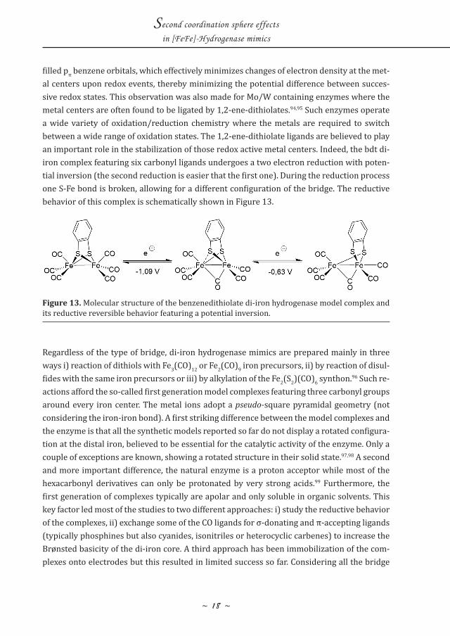
filled pπ benzene orbitals, which effectively minimizes changes of electron density at the met-al centers upon redox events, thereby minimizing the potential difference between succes-sive redox states. This observation was also made for Mo/W containing enzymes where the metal centers are often found to be ligated by 1,2-ene-dithiolates.94,95 Such enzymes operate a wide variety of oxidation/reduction chemistry where the metals are required to switch between a wide range of oxidation states. The 1,2-ene-dithiolate ligands are believed to play an important role in the stabilization of those redox active metal centers. Indeed, the bdt di-iron complex featuring six carbonyl ligands undergoes a two electron reduction with poten-tial inversion (the second reduction is easier that the first one). During the reduction process one S-Fe bond is broken, allowing for a different configuration of the bridge. The reductive behavior of this complex is schematically shown in Figure 13.
Regardless of the type of bridge, di-iron hydrogenase mimics are prepared mainly in three ways i) reaction of dithiols with Fe3(CO)12 or Fe2(CO)9 iron precursors, ii) by reaction of disul-fides with the same iron precursors or iii) by alkylation of the Fe2(S2)(CO)6 synthon.96 Such re-actions afford the so-called first generation model complexes featuring three carbonyl groups around every iron center. The metal ions adopt a pseudo-square pyramidal geometry (not considering the iron-iron bond). A first striking difference between the model complexes and the enzyme is that all the synthetic models reported so far do not display a rotated configura-tion at the distal iron, believed to be essential for the catalytic activity of the enzyme. Only a couple of exceptions are known, showing a rotated structure in their solid state.97,98 A second and more important difference, the natural enzyme is a proton acceptor while most of the hexacarbonyl derivatives can only be protonated by very strong acids.99 Furthermore, the first generation of complexes typically are apolar and only soluble in organic solvents. This key factor led most of the studies to two different approaches: i) study the reductive behavior of the complexes, ii) exchange some of the CO ligands for σ-donating and π-accepting ligands (typically phosphines but also cyanides, isonitriles or heterocyclic carbenes) to increase the Brønsted basicity of the di-iron core. A third approach has been immobilization of the com-plexes onto electrodes but this resulted in limited success so far. Considering all the bridge
Figure 13. Molecular structure of the benzenedithiolate di-iron hydrogenase model complex and its reductive reversible behavior featuring a potential inversion.
1
~ 19 ~
Introduction
variations explored, combined with CO replacement for different ligands, several hundreds of complexes are reported in literature today.
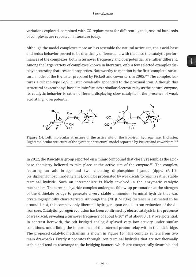
Although the model complexes more or less resemble the natural active site, their acid-base and redox behavior proved to be drastically different and with that also the catalytic perfor-mances of the complexes, both in turnover frequency and overpotential, are rather different. Among the large variety of complexes known in literature, only a few selected examples dis-play interesting features and properties. Noteworthy to mention is the first ‘complete’ struc-tural model of the H-cluster prepared by Pickett and coworkers in 2005.100 The complex fea-tures a cubane-type Fe4S4 cluster covalently appended to the proximal iron. Although this structural hexacarbonyl-based mimic features a similar electron-relay as the natural enzyme, its catalytic behavior is rather different, displaying slow catalysis in the presence of weak acid at high overpotential.
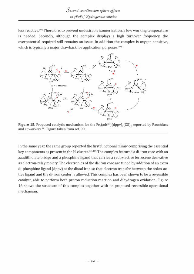
In 2012, the Rauchfuss group reported on a mimic compound that closely resembles the acid-base chemistry believed to take place at the active site of the enzyme.101 The complex, featuring an adt bridge and two chelating di-phosphine ligands (dppv, cis-1,2-bis(diphenylphosphino)ethylene), could be protonated by weak acids to reach a rather stable terminal hydride. Such an intermediate is likely involved in the enzymatic catalytic mechanism. The terminal hydride complex undergoes follow-up protonation at the nitrogen of the dithiolate bridge to generate a very stable ammonium terminal hydride that was crystallographically characterized. Although the (NH)H+-H-(Fe) distance is estimated to be around 1.4 A� , this complex only liberated hydrogen upon one-electron reduction of the di-iron core. Catalytic hydrogen evolution has been confirmed by electrocatalysis in the presence of weak acid, revealing a turnover frequency of about 6∙106 s-1 at about 0.51 V overpotential. In contrast herewith, the pdt bridged analog displayed very low activity under similar conditions, underlining the importance of the internal proton-relay within the adt bridge. The proposed catalytic mechanism is shown in Figure 15. This complex suffers from two main drawbacks. Firstly it operates through iron terminal hydrides that are not thermally stable and tend to rearrange to the bridging isomers which are energetically favorable and
Figure 14. Left: molecular structure of the active site of the iron-iron hydrogenase; H-cluster. Right: molecular structure of the synthetic structural model reported by Pickett and coworkers.100
~ 20 ~
Second coordination sphere effects
in [FeFe]-Hydrogenase mimics
less reactive.102 Therefore, to prevent undesirable isomerization, a low working temperature is needed. Secondly, although the complex displays a high turnover frequency, the overpotential required still remains an issue. In addition the complex is oxygen sensitive, which is typically a major drawback for application purposes.103
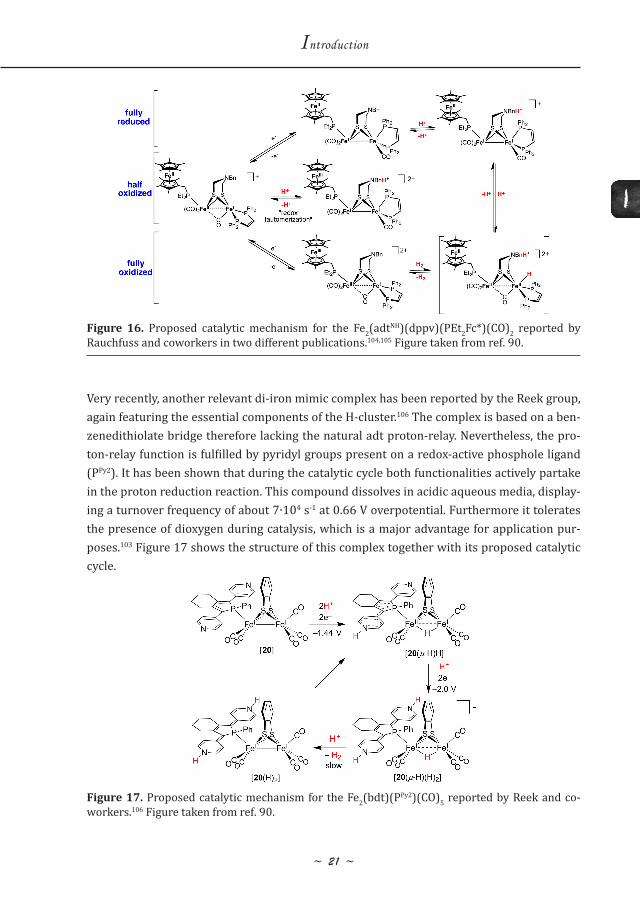
In the same year, the same group reported the first functional mimic comprising the essential key components as present in the H-cluster.104,105 The complex featured a di-iron core with an azadithiolate bridge and a phosphine ligand that carries a redox-active ferrocene derivative as electron-relay moiety. The electronics of the di-iron core are tuned by addition of an extra di-phosphine ligand (dppv) at the distal iron so that electron transfer between the redox-ac-tive ligand and the di-iron center is allowed. This complex has been shown to be a reversible catalyst, able to perform both proton reduction reaction and dihydrogen oxidation. Figure 16 shows the structure of this complex together with its proposed reversible operational mechanism.
Figure 15. Proposed catalytic mechanism for the Fe2(adtNH)(dppv)2(CO)2 reported by Rauchfuss and coworkers.101 Figure taken from ref. 90.
1
~ 2 1 ~
Introduction
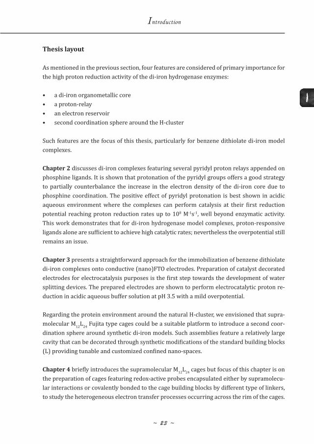
Very recently, another relevant di-iron mimic complex has been reported by the Reek group, again featuring the essential components of the H-cluster.106 The complex is based on a ben-zenedithiolate bridge therefore lacking the natural adt proton-relay. Nevertheless, the pro-ton-relay function is fulfilled by pyridyl groups present on a redox-active phosphole ligand (PPy2). It has been shown that during the catalytic cycle both functionalities actively partake in the proton reduction reaction. This compound dissolves in acidic aqueous media, display-ing a turnover frequency of about 7∙104 s-1 at 0.66 V overpotential. Furthermore it tolerates the presence of dioxygen during catalysis, which is a major advantage for application pur-poses.103 Figure 17 shows the structure of this complex together with its proposed catalytic cycle.
Figure 16. Proposed catalytic mechanism for the Fe2(adtNH)(dppv)(PEt2Fc*)(CO)2 reported by Rauchfuss and coworkers in two different publications.104,105 Figure taken from ref. 90.
Figure 17. Proposed catalytic mechanism for the Fe2(bdt)(PPy2)(CO)5 reported by Reek and co-workers.106 Figure taken from ref. 90.
~ 22 ~
Second coordination sphere effects
in [FeFe]-Hydrogenase mimics
Despite the combined effort of researchers during the last 20 years to accurately mimic structural and functional properties of the hydrogenases enzymes, a synthetic model that is able to reversibly interconvert protons and electrons to hydrogen at fast rates and low driving force has yet to be reported. It has been established, however, that the adt bridge (or proton relays in general) plays a crucial role in catalysis. The presence of an electron reser-voir connected to the di-iron center, although less studied, is also of great influence. A recent report elaborates on experiments in which synthetic di-iron models are installed in the in-active apo-hydrogenase protein, thereby completely restoring the activity of the enzyme.22 This would suggest that the protein environment, second coordination sphere around the H-cluster might play a far more important role than initially anticipated by chemists.
1
~ 23 ~
Introduction
Thesis layout
As mentioned in the previous section, four features are considered of primary importance for the high proton reduction activity of the di-iron hydrogenase enzymes:
• a di-iron organometallic core• a proton-relay • an electron reservoir • second coordination sphere around the H-cluster
Such features are the focus of this thesis, particularly for benzene dithiolate di-iron model complexes.
Chapter 2 discusses di-iron complexes featuring several pyridyl proton relays appended on phosphine ligands. It is shown that protonation of the pyridyl groups offers a good strategy to partially counterbalance the increase in the electron density of the di-iron core due to phosphine coordination. The positive effect of pyridyl protonation is best shown in acidic aqueous environment where the complexes can perform catalysis at their first reduction potential reaching proton reduction rates up to 108 M-1s-1, well beyond enzymatic activity. This work demonstrates that for di-iron hydrogenase model complexes, proton-responsive ligands alone are sufficient to achieve high catalytic rates; nevertheless the overpotential still remains an issue.
Chapter 3 presents a straightforward approach for the immobilization of benzene dithiolate di-iron complexes onto conductive (nano)FTO electrodes. Preparation of catalyst decorated electrodes for electrocatalysis purposes is the first step towards the development of water splitting devices. The prepared electrodes are shown to perform electrocatalytic proton re-duction in acidic aqueous buffer solution at pH 3.5 with a mild overpotential.
Regarding the protein environment around the natural H-cluster, we envisioned that supra-molecular M12L24 Fujita type cages could be a suitable platform to introduce a second coor-dination sphere around synthetic di-iron models. Such assemblies feature a relatively large cavity that can be decorated through synthetic modifications of the standard building blocks (L) providing tunable and customized confined nano-spaces.
Chapter 4 briefly introduces the supramolecular M12L24 cages but focus of this chapter is on the preparation of cages featuring redox-active probes encapsulated either by supramolecu-lar interactions or covalently bonded to the cage building blocks by different type of linkers, to study the heterogeneous electron transfer processes occurring across the rim of the cages.
~ 24 ~
Second coordination sphere effects
in [FeFe]-Hydrogenase mimics
The electrochemical response and kinetics of the electrode of such objects are investigated to demonstrate the feasibility of electron transfer to redox-active moieties encapsulated in the cavity of the nano-spheres, paving the road for catalyst encapsulation and electrocatalytic applications of such systems.
In chapter 4 we prepared several M12L24 assemblies that contain multiple redox-active probes in close proximity to each other, nevertheless they demonstrated to be all electrochemically independent as indicated by their voltammetric behavior. The redox event would thus gener-ate nano-spheres containing several charges at their inside. Considering the Faraday prin-ciple for macroscopic conductive hollow objects where the extra charge resides at their outer shell and extending it to the M12L24 nano-spheres, would imply that charge accumulation at the cage cavity is not allowed, unless it is neutralized by the electrolyte present in solution. Thereby, Chapter 5 firstly describes the preparation of an exceptionally large size electrolyte material that cannot access the cage cavity. Then, it describes the voltammetric response of cages containing either 24 or 12 redox-active probes in the presence of the large size electro-lyte, indicating that such self-assembled cages do have similarities to the macroscopic Fara-day cages. The experiments suggest that charge accumulation at the cavity of these cages causes electrostatic repulsion among the redox-active fragments, providing a driving force for their redistribution toward the outer shell of the cage. As a result of the repulsion, electro-chemical reversibility is lost at slow scan rates indicating the existence of follow up reactivity. Interestingly, addition of small size electrolyte during the experiment, which can enter the cage void to balance charges, restores the typical electrochemical reversible behavior of the redox probes.
Chapter 6 describes two general approaches to introduce a second coordination sphere en-vironment around di-iron hydrogenases models. Encapsulation of the synthetic mimics into M12L24 Fujita type cages is achieved either by supramolecular interaction or covalent bond-ing of the catalyst to the cage building block. Preorganization of proton substrates is accom-plished by introducing acidic moieties at the endohedral position of the cage building blocks. We show that for the covalently encapsulated catalysts, proton preorganization around the di-iron complexes leads to increased catalytic rates compared to cages that do not have this proton preorganization. Most importantly, we show for the first time that changing the lo-cal environment around the catalyst leads to an overpotential that is significantly lowered, underlining the importance of the second coordination sphere around the H-cluster and syn-thetic models.
1
~ 25 ~
Introduction
References
(1) Wrigley, E. A. Phil. Trans. R. Soc. A 2013, 371.(2) Lewis, N. S.; Nocera, D. G. Proc. Natl. Acad. Sci. U.S.A. 2006, 103, 15729.(3) International Energy Agency, http://www.iea.org/publications/freepublications/
publication/CO2EmissionsfromFuelCombustion_Highlights_2016.pdf 2016.(4) Styring, S. Ambio 2012, 41 Suppl 2, 156.(5) Barber, J.; Tran, P. D. J. R. Soc. Interface 2013, 10, 20120984.(6) Berger, W. Prog. Photovolt: Res Appl. 2001, 9, 145.(7) Editorial Nat. Photon. 2012, 6, 129.(8) International Energy Agency, https://www.iea.org/media/freepublications/
technolo gyroadmaps/solar/Solarpv_roadmap_foldout_2010.pdf 2010.(9) Sovacool, B. K. Utilities Policy 2009, 17, 288.(10) Perry, M. L.; Weber, A. Z. J. Electrochem. Soc. 2016, 163, A5064.(11) Mul, G.; Schacht, C.; van Swaaij, W. P. M.; Moulijn, J. A. Chem. Eng. Process. 2012, 51,
137.(12) Jafari, T.; Moharreri, E.; Amin, A.; Miao, R.; Song, W.; Suib, S. Molecules 2016, 21,
900.(13) Merchant, S.; Sawaya, M. R. Plant Cell 2005, 17, 648.(14) Immerdorf, H. Landwirtsch. Jahrb. 1892, 21, 281.(15) Stephenson, M.; Stickland, L. H. Biochem. J 1931, 25, 205.(16) Schilter, D.; Camara, J. M.; Huynh, M. T.; Hammes-Schiffer, S.; Rauchfuss, T. B. Chem.
Rev. 2016, 116, 8693.(17) Volbeda, A.; Charon, M.-H.; Piras, C.; Hatchikian, E. C.; Frey, M.; Fontecilla-Camps, J.
C. Nature 1995, 373, 580.(18) Peters, J. W.; Lanzilotta, W. N.; Lemon, B. J.; Seefeldt, L. C. Science 1998, 282, 1853.(19) Nicolet, Y.; Piras, C.; Legrand, P.; Hatchikian, C. E.; Fontecilla-Camps, J. C. Structure
1999, 7, 13.(20) Pilak, O.; Mamat, B.; Vogt, S.; Hagemeier, C. H.; Thauer, R. K.; Shima, S.; Vonrhein, C.;
Warkentin, E.; Ermler, U. J. Mol. Biol. 2006, 358, 798.(21) Lubitz, W.; Ogata, H.; Rüdiger, O.; Reijerse, E. Chem. Rev. 2014, 114, 4081.(22) Berggren, G.; Adamska, A.; Lambertz, C.; Simmons, T. R.; Esselborn, J.; Atta,
M.; Gam barelli, S.; Mouesca, J. M.; Reijerse, E.; Lubitz, W.; Happe, T.; Artero, V.; Fontecave, M. Nature 2013, 499, 66.
(23) Knörzer, P.; Silakov, A.; Foster, C. E.; Armstrong, F. A.; Lubitz, W.; Happe, T. J. Biol. Chem. 2012, 287, 1489.
(24) Sommer, C.; Adamska-Venkatesh, A.; Pawlak, K.; Birrell, J. A.; Rudiger, O.; Reijerse,
~ 26 ~
Second coordination sphere effects
in [FeFe]-Hydrogenase mimics
E. J.; Lubitz, W. J. Am. Chem. Soc. 2017, 139, 1440.(25) Adamska, A.; Silakov, A.; Lambertz, C.; Rüdiger, O.; Happe, T.; Reijerse, E.; Lubitz, W.
Angew. Chem. Int. Ed. 2012, 51, 11458.(26) Greco, C.; Bruschi, M.; Fantucci, P.; Ryde, U.; De Gioia, L. ChemPhysChem 2011, 12,
3376.(27) Lubner, C. E.; Grimme, R.; Bryant, D. A.; Golbeck, J. H. Biochemistry 2010, 49, 404.(28) Krassen, H.; Schwarze, A.; Friedrich, B.; Ataka, K.; Lenz, O.; Heberle, J. ACS Nano
2009, 3, 4055.(29) Iwuchukwu, I. J.; Vaughn, M.; Myers, N.; O’Neill, H.; Frymier, P.; Bruce, B. D. Nat
Nano 2010, 5, 73.(30) Cook, T. R.; Dogutan, D. K.; Reece, S. Y.; Surendranath, Y.; Teets, T. S.; Nocera, D. G.
Chem. Rev. 2010, 110, 6474.(31) Durbin, D. J.; Malardier-Jugroot, C. Int. J. Hydrogen Energy 2013, 38, 14595.(32) Sakintuna, B.; Lamari-Darkrim, F.; Hirscher, M. Int. J. Hydrogen Energy 2007, 32,
1121.(33) Ciamician, G. Science 1912, 36, 385.(34) Fujishima, A.; Honda, K. Nature 1972, 238, 37.(35) Khaselev, O.; Turner, J. A. Science 1998, 280, 425.(36) Reece, S. Y.; Hamel, J. A.; Sung, K.; Jarvi, T. D.; Esswein, A. J.; Pijpers, J. J. H.; Nocera,
D. G. Science 2011, 334, 645.(37) Abdi, F. F.; Han, L.; Smets, A. H. M.; Zeman, M.; Dam, B.; van de Krol, R. Nat.
Commun. 2013, 4, 2195.(38) Esiner, S.; Willems, R. E. M.; Furlan, A.; Li, W.; Wienk, M. M.; Janssen, R. A. J. J. Mater.
Chem. A 2015, 3, 23936.(39) Zhang, X.; Zhang, B.; Cao, K.; Brillet, J.; Chen, J.; Wang, M.; Shen, Y. J. Mater. Chem. A
2015, 3, 21630.(40) Luo, J.; Im, J.-H.; Mayer, M. T.; Schreier, M.; Nazeeruddin, M. K.; Park, N.-G.; Tilley, S.
D.; Fan, H. J.; Grätzel, M. Science 2014, 345, 1593.(41) Shi, X.; Zhang, K.; Shin, K.; Ma, M.; Kwon, J.; Choi, I. T.; Kim, J. K.; Kim, H. K.; Wang, D.
H.; Park, J. H. Nano Energy 2015, 13, 182.(42) Torella, J. P.; Gagliardi, C. J.; Chen, J. S.; Bediako, D. K.; Colón, B.; Way, J. C.; Silver, P.
A.; Nocera, D. G. Proc. Natl. Acad. Sci. U.S.A. 2015, 112, 2337.(43) Liu, C.; Colón, B. C.; Ziesack, M.; Silver, P. A.; Nocera, D. G. Science 2016, 352, 1210.(44) Utschig, L. M.; Silver, S. C.; Mulfort, K. L.; Tiede, D. M. J. Am. Chem. Soc. 2011, 133,
16334.(45) Silver, S. C.; Niklas, J.; Du, P.; Poluektov, O. G.; Tiede, D. M.; Utschig, L. M. J. Am.
Chem. Soc. 2013, 135, 13246.
1
~ 27 ~
Introduction
(46) Gorka, M.; Schartner, J.; van der Est, A.; Rögner, M.; Golbeck, J. H. Biochemistry 2014, 53, 2295.
(47) Applegate, A. M.; Lubner, C. E.; Knörzer, P.; Happe, T.; Golbeck, J. H. Photosynth. Res. 2016, 127, 5.
(48) Lubner, C. E.; Applegate, A. M.; Knörzer, P.; Ganago, A.; Bryant, D. A.; Happe, T.; Gol beck, J. H. Proc. Natl. Acad. Sci. U.S.A. 2011, 108, 20988.
(49) Kato, M.; Cardona, T.; Rutherford, A. W.; Reisner, E. J. Am. Chem. Soc. 2013, 135, 10610.
(50) Yehezkeli, O.; Tel-Vered, R.; Wasserman, J.; Trifonov, A.; Michaeli, D.; Nechushtai, R.; Willner, I. Nat. Commun. 2012, 3, 742.
(51) Lamle, S. E.; Vincent, K. A.; Halliwell, L. M.; Albracht, S. P. J.; Armstrong, F. A. Dalton Trans. 2003, 4152.
(52) Rosser, T. E.; Gross, M. A.; Lai, Y.-H.; Reisner, E. Chem. Sci. 2016, 7, 4024.(53) Li, F.; Fan, K.; Xu, B.; Gabrielsson, E.; Daniel, Q.; Li, L.; Sun, L. J. Am. Chem. Soc. 2015,
137, 9153.(54) Ashford, D. L.; Gish, M. K.; Vannucci, A. K.; Brennaman, M. K.; Templeton, J. L.;
Papan ikolas, J. M.; Meyer, T. J. Chem. Rev. 2015, 115, 13006.(55) Walter, M. G.; Warren, E. L.; McKone, J. R.; Boettcher, S. W.; Mi, Q.; Santori, E. A.;
Lew is, N. S. Chem. Rev. 2010, 110, 6446.(56) Yu, Z.; Li, F.; Sun, L. Energy Environ. Sci. 2015, 8, 760.(57) Li, F.; Jiang, Y.; Zhang, B.; Huang, F.; Gao, Y.; Sun, L. Angew. Chem. Int. Ed. 2012, 51,
2417.(58) Herrero, C.; Quaranta, A.; Protti, S.; Leibl , W.; Rutherford, A. W.; Fallahpour, D. R.;
Charlot, M.-F.; Aukauloo, A. Chem. Asian J. 2011, 6, 1335.(59) Kaveevivitchai, N.; Chitta, R.; Zong, R.; El Ojaimi, M.; Thummel, R. P. J. Am. Chem.
Soc. 2012, 134, 10721.(60) Ashford, D. L.; Stewart, D. J.; Glasson, C. R.; Binstead, R. A.; Harrison, D. P.; Norris,
M. R.; Concepcion, J. J.; Fang, Z.; Templeton, J. L.; Meyer, T. J. Inorg. Chem. 2012, 51, 6428.
(61) Natali, M.; Argazzi, R.; Chiorboli, C.; Iengo, E.; Scandola, F. Chem. Eur. J. 2013, 19, 9261.
(62) Zheng, B.; Sabatini, R. P.; Fu, W.-F.; Eum, M.-S.; Brennessel, W. W.; Wang, L.; McCa mant, D. W.; Eisenberg, R. Proc. Natl. Acad. Sci. U.S.A. 2015, 112, E3987.
(63) Poddutoori, P.; Co, D. T.; Samuel, A. P. S.; Kim, C. H.; Vagnini, M. T.; Wasielewski, M. R. Energy Environ. Sci. 2011, 4, 2441.
(64) Song, L.-C.; Tang, M.-Y.; Mei, S.-Z.; Huang, J.-H.; Hu, Q.-M. Organometallics 2007, 26, 1575.
(65) Kluwer, A. M.; Kapre, R.; Hartl, F.; Lutz, M.; Spek, A. L.; Brouwer, A. M.; van
~ 28 ~
Second coordination sphere effects
in [FeFe]-Hydrogenase mimics
Leeuwen, P. W. N. M.; Reek, J. N. H. Proc. Natl. Acad. Sci. U.S.A. 2009, 106, 10460.(66) Alibabaei, L.; Brennaman, M. K.; Norris, M. R.; Kalanyan, B.; Song, W.; Losego, M.
D.; Concepcion, J. J.; Binstead, R. A.; Parsons, G. N.; Meyer, T. J. Proc. Natl. Acad. Sci. U.S.A. 2013, 110, 20008.
(67) Ji, Z.; He, M.; Huang, Z.; Ozkan, U.; Wu, Y. J. Am. Chem. Soc. 2013, 135, 11696.(68) Alibabaei, L.; Sherman, B. D.; Norris, M. R.; Brennaman, M. K.; Meyer, T. J. Proc. Natl.
Acad. Sci. U.S.A. 2015, 112, 5899.(69) Bard, A. J.; Faulkner, L. R. Electrochemical Methods: Fundamentals and
Applications; Wiley, 2000.(70) Hambourger, M.; Gervaldo, M.; Svedruzic, D.; King, P. W.; Gust, D.; Ghirardi, M.;
Moore, A. L.; Moore, T. A. J. Am. Chem. Soc. 2008, 130, 2015.(71) Dau, H.; Zaharieva, I. Acc. Chem. Res. 2009, 42, 1861.(72) Artero, V.; Saveant, J.-M. Energy Environ. Sci. 2014, 7, 3808.(73) Costentin, C.; Passard, G.; Savéant, J.-M. J. Am. Chem. Soc. 2015, 137, 5461.(74) Gersten, S. W.; Samuels, G. J.; Meyer, T. J. J. Am. Chem. Soc. 1982, 104, 4029.(75) Gilbert, J. A.; Eggleston, D. S.; Murphy, W. R.; Geselowitz, D. A.; Gersten, S. W.; Hodg
son, D. J.; Meyer, T. J. J. Am. Chem. Soc. 1985, 107, 3855.(76) Duan, L.; Fischer, A.; Xu, Y.; Sun, L. J. Am. Chem. Soc. 2009, 131, 10397.(77) Kärkäs, M. D.; Verho, O.; Johnston, E. V.; A� kermark, B. Chem. Rev. 2014, 114, 11863.(78) Imahori, H. ChemSusChem 2015, 8, 426.(79) Hetterscheid, D. G. H.; Reek, J. N. H. Chem. Commun. 2011, 47, 2712.(80) Blakemore, J. D.; Crabtree, R. H.; Brudvig, G. W. Chem. Rev. 2015, 115, 12974.(81) Singh, A.; Spiccia, L. Coord. Chem. Rev. 2013, 257, 2607.(82) Bullock, R. M.; Appel, A. M.; Helm, M. L. Chem Commun (Camb) 2014, 50, 3125.(83) Wang, M.; Chen, L.; Sun, L. Energy Environ. Sci. 2012, 5, 6763.(84) Razavet, M.; Artero, V.; Fontecave, M. Inorg. Chem. 2005, 44, 4786.(85) Wilson, A. D.; Newell, R. H.; McNevin, M. J.; Muckerman, J. T.; Rakowski DuBois, M.;
DuBois, D. L. J. Am. Chem. Soc. 2006, 128, 358.(86) Dahl, L. F.; Wei, C.-H. Inorg. Chem. 1963, 2, 328.(87) Winter, A.; Zsolnai, L.; Hüttner, G. Naturforsch B 1982, 37, 1430.(88) Seyferth, D.; Womack, G. B.; Gallagher, M. K.; Cowie, M.; Hames, B. W.; Fackler, J. P.;
Mazany, A. M. Organometallics 1987, 6, 283.(89) Li, H.; Rauchfuss, T. B. J. Am. Chem. Soc. 2002, 124, 726.(90) Rauchfuss, T. B. Acc. Chem. Res. 2015, 48, 2107.(91) Felton, G. A. N.; Vannucci, A. K.; Chen, J.; Lockett, L. T.; Okumura, N.; Petro, B. J.; Za
kai, U. I.; Evans, D. H.; Glass, R. S.; Lichtenberger, D. L. J. Am. Chem. Soc. 2007, 129, 12521.
1
~ 29 ~
Introduction
(92) Capon, J.-F.; Gloaguen, F.; Schollhammer, P.; Talarmin, J. J. Electroanal. Chem. 2004, 566, 241.
(93) Capon, J.-F.; Gloaguen, F.; Schollhammer, P.; Talarmin, J. J. Electroanal. Chem. 2006, 595, 47.
(94) Joshi, H. K.; Inscore, F. E.; Schirlin, J. T.; Dhawan, I. K.; Carducci, M. D.; Bill, T. G.; En emark, J. H. Inorg. Chim. Acta 2002, 337, 275.
(95) Joshi, H. K.; Cooney, J. J. A.; Inscore, F. E.; Gruhn, N. E.; Lichtenberger, D. L.; Enemark, J. H. Proc. Natl. Acad. Sci. U.S.A. 2003, 100, 3719.
(96) Li, Y.; Rauchfuss, T. B. Chem. Rev. 2016, 116, 7043.(97) Munery, S.; Capon, J. F.; De Gioia, L.; Elleouet, C.; Greco, C.; Petillon, F. Y.; Schollham
mer, P.; Talarmin, J.; Zampella, G. Chemistry 2013, 19, 15458.(98) Wang, W.; Rauchfuss, T. B.; Moore, C. E.; Rheingold, A. L.; De Gioia, L.; Zampella, G.
Chemistry 2013, 19, 15476.(99) Matthews, S. L.; Heinekey, D. M. Inorg. Chem. 2010, 49, 9746.(100) Tard, C.; Liu, X.; Ibrahim, S. K.; Bruschi, M.; De Gioia, L.; Davies, S. C.; Yang, X.;
Wang, L.-S.; Sawers, G.; Pickett, C. J. Nature 2005, 433, 610.(101) Carroll, M. E.; Barton, B. E.; Rauchfuss, T. B.; Carroll, P. J. J. Am. Chem. Soc. 2012,
134, 18843.(102) van der Vlugt, J. I.; Rauchfuss, T. B.; Whaley, C. M.; Wilson, S. R. J. Am. Chem. Soc.
2005, 127, 16012.(103) Wakerley, D. W.; Reisner, E. Energy Environ. Sci. 2015, 8, 2283.(104) Camara, J. M.; Rauchfuss, T. B. Nat. Chem. 2012, 4, 26.(105) Lansing, J. C.; Camara, J. M.; Gray, D. E.; Rauchfuss, T. B. Organometallics 2014.(106) Becker, R.; Amirjalayer, S.; Li, P.; Woutersen, S.; Reek, J. N. H. Sci. Adv. 2016, 2.


![1 [2010] · Mariana Caraballo Dra. Gabriela Gusis ... Trad. Carolina Mozo Sartorio ... Dr. Juan Carlos Maqueda Dr. Eugenio Raúl Zaffaroni Dra](https://img.pdfslide.us/doc/110x75/5bb8217709d3f2333b8bef26/1-2010-mariana-caraballo-dra-gabriela-gusis-trad-carolina-mozo-sartorio.jpg)

![Selective isolation of gold facilitated by second-sphere ... · CD rings, facilitates a highly specific second-sphere coordination involving, not only the [AuBr 4] anion, but also](https://img.pdfslide.us/doc/110x75/5fecd9671e2d5400305ea1c6/selective-isolation-of-gold-facilitated-by-second-sphere-cd-rings-facilitates.jpg)


![Proton Relay Effects in Pyridyl‐Appended Hydrogenase ...publications.tno.nl/publication/34634128/gShHt8/zaffaroni-2019-proton.pdf · Riccardo Zaffaroni,[a] Wojciech I. Dzik,[a]](https://img.pdfslide.us/doc/110x75/5e2b3764c51f1f7dee57abb9/proton-relay-effects-in-pyridylaappended-hydrogenase-riccardo-zaffaronia.jpg)

![UvA-DARE (Digital Academic Repository) Second coordination … · Zaffaroni, R. (2017). Second coordination sphere effects in [FeFe]-Hydrogenase mimics General rights It is not permitted](https://img.pdfslide.us/doc/110x75/5bd5916e09d3f2463e8bf180/uva-dare-digital-academic-repository-second-coordination-zaffaroni-r-2017.jpg)


![[Revista ATJ 12] Entrevista a Zaffaroni](https://img.pdfslide.us/doc/110x75/55cf9008550346703ba292fa/revista-atj-12-entrevista-a-zaffaroni.jpg)