Embed Size (px)
Citation preview
UvA-DARE is a service provided by the library of the University of Amsterdam (http://dare.uva.nl)
UvA-DARE (Digital Academic Repository)
High resolution magnetic resonance imaging anatomy of the orbit
Ettl, A.
Link to publication
Citation for published version (APA):Ettl, A. (2000). High resolution magnetic resonance imaging anatomy of the orbit
General rightsIt is not permitted to download or to forward/distribute the text or part of it without the consent of the author(s) and/or copyright holder(s),other than for strictly personal, individual use, unless the work is under an open content license (like Creative Commons).
Disclaimer/Complaints regulationsIf you believe that digital publication of certain material infringes any of your rights or (privacy) interests, please let the Library know, statingyour reasons. In case of a legitimate complaint, the Library will make the material inaccessible and/or remove it from the website. Please Askthe Library: http://uba.uva.nl/en/contact, or a letter to: Library of the University of Amsterdam, Secretariat, Singel 425, 1012 WP Amsterdam,The Netherlands. You will be contacted as soon as possible.
Download date: 21 Jun 2018
17 17
ChapterChapter 2
HIGHH RESOLUTION MAGNETIC RESONANCE IMAGING mrr MFTTPrwA^rrTT A D H M T T A T AivrATrw/rv
Arminn Ettl12, Josef Kramer3, Albert Daxer4, Leo Koornneef
11 Orbital Center, Department of Ophthalmology, Academic Medical Center, Amsterdam, The Netherlands departmentt of Neuro-Ophthalmology, Oculoplastic and Orbital Surgery, General Hospital, St. Poelten, Austria 3CTT and MR Institute, Linz, Austria 44 Department of Ophthalmology, University Hospital, Innsbruck, Austria
Ophthalmology,Ophthalmology, 104:869-877, 1997
INTRODUCTION N
Imagingg techniques have become an indispensable diagnostic tooll in ophthalmology. In most centers, computed tomography iss still the method of choice for orbital imaging because of itss low costs and excellent depiction of bony details.12 The resolutionn in computed tomography within the orbit has been shownn to be sufficient to demonstrate structures such as the ophthalmicc artery and some of its branches, the superior ophthalmicc vein, branches of the frontal nerve, or oculomotor nerves.lAA Compared with computed tomography, orbital magneticc resonance imaging (MRI) provides a better soft-tissuee contrast resolution and is capable of multiplanar imaging,, but has the disadvantage of poor delineation of bones.55 7 Because there is no exposure to ionizing radiation, high-resolutionn MRI is an excellent tool for anatomical studiess in vivo.8 9 Additionally, biochemical informations may bee obtained during the same examination by means of proton magneticc resonance spectroscopy10 in the future. Although manyy papers have been published regarding the diagnosis of orbitall space occupying lesions using MRI,57" 16 there is not muchh detailed information about MRI anatomy of the orbit in thee literature. There are descriptions of the gross anatomy off the orbit on MRI scans and early surface-coil studies of orbitall anatomy."12'719 We find some high resolution MRI scanss of the orbit in Dutton 's anatomic atlas20 and the textbook byy De Potter and Shields14; however, a discussion regarding
thee anatomic interpretation of the structures in the images is nott available. In this study, the MRI anatomy of the arteries, veinss and cranial nerves of the orbit is described. We do not focuss on imaging details of the optic nerve because this has beenn described previously.1"2 '8 To facilitate the interpretation off the magnetic resonance images, we briefly recall the neurovascularr orbital structures that can be visualized in imagingg studies (Figs 1 and 2).
MATERIALL AND METHODS
Sixx healthy subjects, aged 29 to 32 years, and one 54-year-old patientt with chronic oculomotor nerve paralysis on the left sidee (which minimized motion artifacts) were examined after informedd consent had been obtained (n = 7 orbits). Magnetic resonancee imaging of the orbit was performed on a 1 Tesla scannerr (Impact, Siemens, Germany) using a surface coil with aa diameter of 10 cm. Tl - weighted images of the orbit were obtainedd using spin-echo sequences with an echo time (TE) off 15 msec and a repetition time (TR) of 440 to 520 msec. Imagingg planes included axial, coronal and oblique-sagittal (parallell to the optic nerve) sections. Contiguous 2- to 3-mm slicess were obtained. The field of view in the original images rangedd between 140 x 140 mm with a 256 x 256 matrix and 2300 x 230 mm with a 512 x 512 matrix, resulting in a pixel sizee and theoretical spatial resolution of 0.4 to 0.5 mm.
1818 Chapter 2
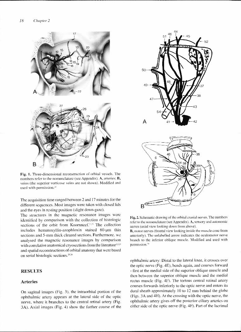
Fig.. 1. Three-dimensional reconstruction of orbital vessels. The numberss refer to the nomenclature (see Appendix). A, arteries; B, veinss (the superior vorticose veins are not shown). Modified and usedd with permission.24
Thee acquisition time ranged between 2 and 17 minutes for the differentt sequences. Most images were taken with closed lids andd the eyes in resting position (slight down-gaze). Thee structures in the magnetic resonance images were identifiedd by comparison with the collection of histologic sectionss of the orbit from Koornneef.2122 The collection includess hematoxyllin-azophloxin stained 60-pm thin sectionss and 5-mm thick cleared sections. Furthermore, we analysedd the magnetic resonance images by comparison withh correlative anatomical cryosections from the literature'221
andd spatial reconstructions of orbital anatomy that were based onn serial histologic sections.2024
R E S U L T S S
Arter ies s
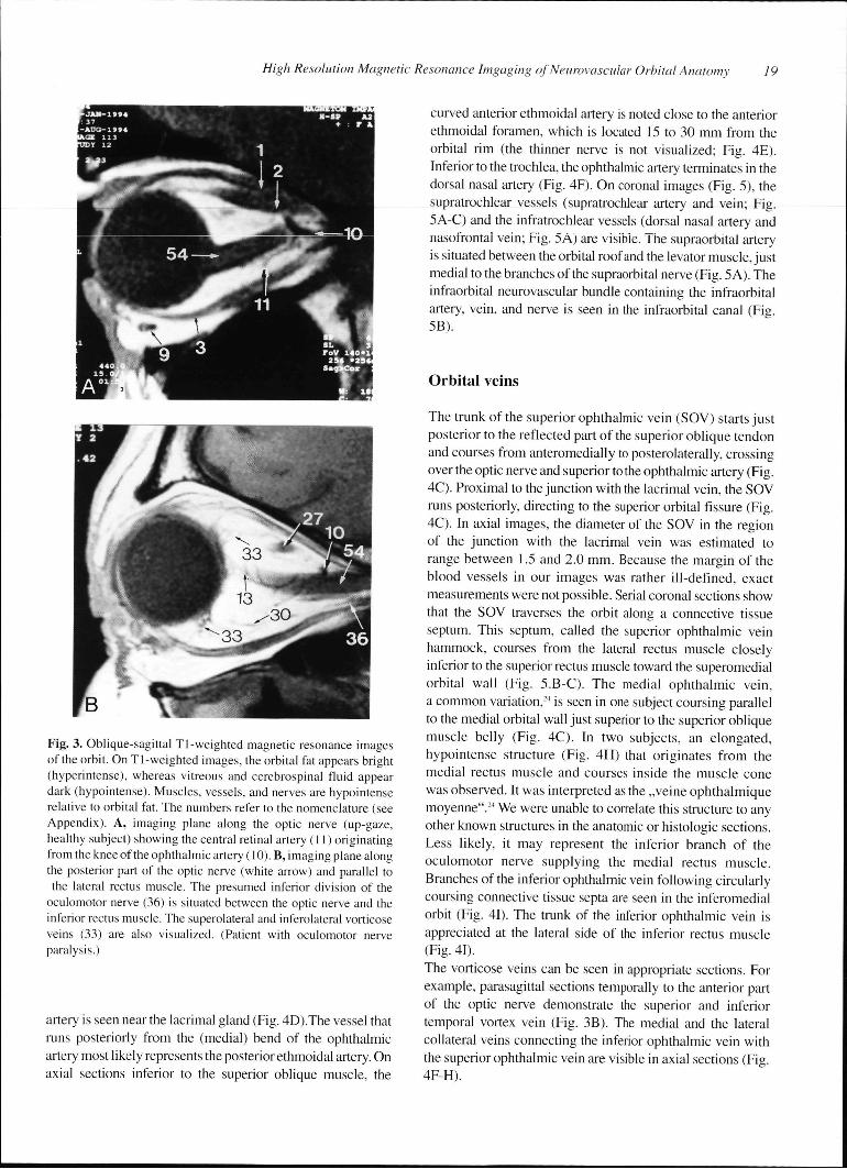
Onn sagittal images (Fig. 3), the intraorbital portion of the ophthalmicc artery appears at the lateral side of the optic nerve,, where it branches to the central retinal artery (Fig. 3A).. Axial images (Fig. 4) show the further course of the
Fig.. 2. Schematic drawing of the orbital cranial nerves. The numbers referr to the nomenclature (see Appendix). A, sensory and autonomic nervess (axial view looking down from above). B,, motor nerves (frontal view looking inside the muscle cone from anteriorly).. The unlabelled arrow indicates the oculomotor nerve branchh to the inferior oblique muscle. Modified and used with permission.20 0
ophthalmicc artery: Distal to the lateral knee, it crosses over thee optic nerve (Fig. 4E), bends again, and courses forward -- first at the medial side of the superior oblique muscle and thenn between the superior oblique muscle and the medial rectuss muscle (Fig. 4F). The tortous central retinal artery coursess forwards inferiorly to the optic nerve and enters its durall sheath approximately 10 to 12 mm behind the globe (Figs.. 3A and 4H). At the crossing with the optic nerve, the ophthalmicc artery gives off the posterior ciliary arteries on eitherr side of the optic nerve (Fig. 4F). Part of the lacrimal
HighHigh Resolution Magnetic Resonance Imgaging of Neurovascular Orbital Anatomy 19
Fig.. 3. Oblique-sagittal T1 -weighted magnetic resonance images off the orbit. On Tl-weighted images, the orbital fat appears bright (hyperintense),, whereas vitreous and cerebrospinal fluid appear darkk (hypointense). Muscles, vessels, and nerves are hypointense relativee to orbital fat. The numbers refer to the nomenclature (see Appendix).. A, imaging plane along the optic nerve (up-gaze, healthyy subject) showing the central retinal artery (11) originating fromm the knee of the ophthalmic artery (10). B, imaging plane along thee posterior part of the optic nerve (white arrow) and parallel to thee lateral rectus muscle. The presumed inferior division of the
oculomotorr nerve (36) is situated between the optic nerve and the inferiorr rectus muscle. The superolateral and inferolateral vorticose veinss (33) are also visualized. (Patient with oculomotor nerve paralysis.) )
arteryy is seen near the lacrimal gland (Fig. 4D).The vessel that runss posteriorly from the (medial) bend of the ophthalmic arteryy most likely represents the posterior ethmoidal artery. On axiall sections inferior to the superior oblique muscle, the
curvedd anterior ethmoidal artery is noted close to the anterior ethmoidall foramen, which is located 15 to 30 mm from the orbitall rim (the thinner nerve is not visualized; Fig. 4E). Inferiorr to the trochlea, the ophthalmic artery terminates in the dorsall nasal artery (Fig. 4F). On coronal images (Fig. 5), the supratrochlearr vessels (supratrochlear artery and vein; Fig. 5A-C)) and the infratrochlear vessels (dorsal nasal artery and nasofrontall vein; Fig. 5A) are visible. The supraorbital artery iss situated between the orbital roof and the levator muscle, just mediall to the branches of the supraorbital nerve (Fig. 5 A). The infraorbitall neurovascular bundle containing the infraorbital artery,, vein, and nerve is seen in the infraorbital canal (Fig. 5B). .
Orbitall veins
Thee trunk of the superior ophthalmic vein (SOV) starts just posteriorr to the reflected part of the superior oblique tendon andd courses from anteromedially to posterolaterally, crossing overr the optic nerve and superior to the ophthalmic artery (Fig. 4C).. Proximal to the junction with the lacrimal vein, the SOV runss posteriorly, directing to the superior orbital fissure (Fig. 4C).. In axial images, the diameter of the SOV in the region off the junction with the lacrimal vein was estimated to rangee between 1.5 and 2.0 mm. Because the margin of the bloodd vessels in our images was rather ill-defined, exact measurementss were not possible. Serial coronal sections show thatt the SOV traverses the orbit along a connective tissue septum.. This septum, called the superior ophthalmic vein hammock,, courses from the lateral rectus muscle closely inferiorr to the superior rectus muscle toward the superomedial orbitall wall (Fig. 5.B-C). The medial ophthalmic vein, aa common variation,24 is seen in one subject coursing parallel too the medial orbital wall just superior to the superior oblique musclee belly (Fig. 4C). In two subjects, an elongated, hypointensee structure (Fig. 4H) that originates from the mediall rectus muscle and courses inside the muscle cone wass observed. It was interpreted as the „veine ophthalmique moyenne".244 We were unable to correlate this structure to any otherr known structures in the anatomic or histologic sections. Lesss likely, it may represent the inferior branch of the oculomotorr nerve supplying the medial rectus muscle. Branchess of the inferior ophthalmic vein following circularly coursingg connective tissue septa are seen in the inferomedial orbitt (Fig. 41). The trunk of the inferior ophthalmic vein is appreciatedd at the lateral side of the inferior rectus muscle (Fig.. 41).
Thee vorticose veins can be seen in appropriate sections. For example,, parasagittal sections temporally to the anterior part off the optic nerve demonstrate the superior and inferior temporall vortex vein (Fig. 3B). The medial and the lateral collaterall veins connecting the inferior ophthalmic vein with thee superior ophthalmic vein are visible in axial sections (Fig. 4F-H). .
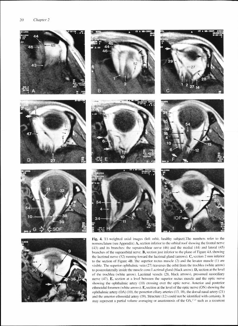
Fig.. 4. Tl-weighted axial images (left orbit, healthy subject).The numbers refer to the nomenclaturee (see Appendix). A, section inferior to the orbital roof showing the frontal nerve (43)) and its branches: the supratrochlear nerve (46) and the medial (44) and lateral (45) branchess of the supraorbital nerve. B, section just inferior to the plane of Figure 4A showing thee lacrimal nerve (52) running toward the lacrimal gland (arrows). C, section 2 mm inferior too the section of Figure 4B. The superior rectus muscle (2) and the levator muscle (1) are visible.. The superior ophthalmic vein (27) traverses the orbit from the trochlea (white arrow) too posterolaterally inside the muscle cone.Lacrimal gland (black arrow). D, section at the level off the trochlea (white arrow). Lacrimal vessels (28. black arrows), presumed nasociliary nervee (47). E, section at a level between the superior rectus muscle and the optic nerve showingg the ophthalmic artery (10) crossing over the optic nerve. Anterior and posterior ethmoidall foramen (white arrows). F, section at the level of the optic nerve (ON) showing the ophthalmicc artery (OA) (10), the posterior ciliary arteries (13, 18), the dorsal nasal artery (21) andd the anterior ethmoidal artery (19). Structure (12) could not be identified with certainty. It mayy represent a partial volume averaging or anastomosis of the OA,27:'' such as a recurrent
HighHigh Resolution Magnetic Resonance Imgaging of Neurovascular Orbital Anatomy 21
meningeall branch3127". Presumed posterior ethmoidal artery (small whitee arrow). G, section at the level of the optic nerve showing thee presumed abducens nerve3' between the optic nerve and the laterall rectus muscle,5 the medial and lateral collateral veins,31-32
andd presumably the ciliary ganglion1" anterior to the knee of the ophthalmicc artery.'"Superior orbital fissure (SOF). H, section at the levell of the horizontal rectus muscles, inferior to the posterior optic nerve,, showing the central retinal artery (11) and the presumed „veinee ophthalmique moyenne" (34), a variation that originates from thee medial rectus muscle to drain into the cavernous sinus.24 I, sectionn through the posterior part of the inferior rectus muscle (3) and thee inferior orbital fissure (IOF), showing the inferior ophthalmic vein (30),, the medial and lateral collateral veins (31, 32), the orbital musclee of Muller (M), and the lacrimal sac (white arrow heads). J, sectionn at the level of the inferior orbital fissure (IOF): The structure (36),, which courses along the lateral border of the inferior rectus musclee (3), either represents the branch of the oculomotor nerve supplyingg the inferior oblique muscle (9) or a muscular branch of the inferiorr ophthalmic vein. Orbital muscle of Muller (M).
consistentlyy on coronal images at the lateral border of the inferiorr rectus muscle, most likely represents the branch of thee inferior division of the oculomotor nerve to the the inferiorr oblique muscle (Fig. 4J and 5B). Correlative anatomic sectionss in the frontal plane2022 and spatial reconstructions2024
showw the branch of the oculomotor nerve supplying the inferiorr oblique muscle in this location. Onn axial images, the abducens nerve may be visible between thee optic nerve and the lateral rectus muscle (Fig. 4J). The 2-- to 3-mm long, hypointense structure that is situated betweenn optic nerve and lateral rectus muscle just anterior too the lateral knee of the ophthalmic artery and approximately 11 cm anterior to the superior ophthalmic fissure might be thee ciliary ganglion (Fig. 4G). The superior division of the oculomotorr nerve and the trochlear nerve are not visualized in thee magnetic resonance images.
Motorr nerves
Becausee of the crowding of anatomic structures in the orbital apex,, the inferior division of the oculomotor nerve cannot reliablyy be distinguished from other structures. However, in onee subject with paralytic atrophy of the rectus muscles, an elongatedd structure between the optic nerve and the inferior rectuss muscle was observed in sagittal magnetic resonance imagess (Fig. 3B).This was interpreted as the trunk of the inferiorr division of the oculomotor nerve. Thee structure that can be seen on axial images, and more
Sensoryy and Autonomic nerves
Thee ophthalmic division of the trigeminal nerve branches intoo the frontal, lacrimal, and nasociliary nerves that can be clearlyy seen on MRI. The frontal nerve with its three branches (supratrochlearr nerve, medial and lateral branch of supraorbital nerve)) is noted on axial (Fig. 4A) and coronal (Figs 5B-C) slicess superior to the levator palpebrae superioris muscle. The lacrimall nerve is seen in the upper tier of the orbit on axial sectionss (Fig. 4B). Axial sections at the level of the SOV (Fig. 4D)) demonstrate the nasociliary nerve as it travels anteriorly betweenn the superior oblique and medial rectus muscles.
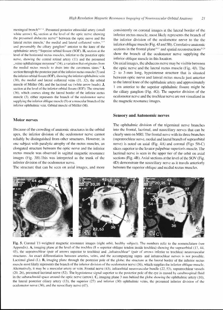
Fig.. 5. Coronal TI-weighted magnetic resonance images (right orbit, healthy subject). The numbers refer to the nomenclature (see Appendix).. A, imaging plane at the level of the trochlea (8 = superior oblique tendon inside trochlea) showing the supraorbital (17, 44, 45),, the supratrochlear (pair of arrows superior to trochlea) and „infratrochlear" (pair of arrows inferior to trochlea) neurovascular structures.. An exact differentiation between arteries, veins, and the accompanying supra- and infratrochlear nerves is not possible. Lacrimall gland (L). B, imaging piane through the posterior pole of the globe: the structure at the lateral border of the inferior rectus musclee most likely represents the branch of the inferior division of the oculomotor nerve (36), which supplies the inferior oblique muscle. Alternatively,, it may be a muscular artery or vein. Frontal nerve (43), infraorbital neurovascular bundle (22, 53), supratrochlear vessels (20,, 26), presumed lacrimal nerve (52). The hypointense signal superior to the posterior pole of the eye is caused by cerebrospinal fluid inn the subarachnoid space around the optic nerve (arrow). C, imaging plane 3 mm behind the globe showing the ophthalmic artery (10), thee lateral posterior ciliary artery (13), the superior (27) and inferior (30) ophthalmic veins, the presumed inferior division of the oculomotorr nerve (36), and the nasociliary nerve (47).
2222 Chapter 2
AA reliable identification of the tiny ciliary nerves was not possiblee in the magnetic resonance images. Thee infraorbital neurovascular bundle consisting of the infraorbitall nerve and vessels is visualized inside the infraorbitall canal on coronal images (Fig. 5B).
DISCUSSION N
Thee fat content of the orbit is responsible for the excellent contrastt in orbital MRI, allowing for better detection of small anatomicc structures. Fat appears bright (hyperintense) on Tl-weightedd images, and other structures such as muscles, vessels,, and nerves are darker (hypointense) than orbital fat. Thee optic nerve exhibits MRI signal characteristics similar to thosee of white matter of the brain because of its myelinated nervee fibers.19 Blood vessels (especially arteries) appear dark inn Tl-weighted magnetic resonance images. This is because thee protons of flowing blood that have been excited by a radiofrequencyy pulse pass outside the imaging slice before theirr signal can be detected.2^ Althoughh we have used a slice thickness of 2 to 3 mm, partial volumee averaging' enabled a visualization of relatively long partss of vascular structures, such as the superior ophthalmic veinn (Fig. AC). When the examined structure is partially out off the imaging slice, hypointense or thin segments within its coursee (Fig. 4.E-F) are the consequence.* Thus, partial volume averagingg is a potential source of error during the identification off anatomic structures in MRI. To circumvent this problem and avoidd mistakes, we have always analyzed series of adjacent imagingg slices and the corresponding coronal sections or other orientations. . Becausee of the aforementioned signal void of flowing blood, majorr vessels in our images were usually darker than other structuress such as muscles and nerves. In general, arteries showedd a curved course compared with the more straight veinss and nerves. These facts, together with a detailed knowledgee of orbital topographical2027-' and sectional anatomy1222-,, allowed the identification of various vascular structuress on MRI. Knowledge of the mean diameters of the differentt arteries (e.g., ophthalmic artery: 1.3-1.4 mm, lacrimal artery:: 0.7 mm, central retinal artery: 0.5 mm)'2 was also usefull for the analysis, although the vessel diameters estimatedd in the magnetic resonance images slightly exceeded thee real anatomical diameter. This discrepancy in the vessel diameterr between MRI studies and anatomic studies32 may be duee to the fact that the MRI-system measures not only the bloodd flow but also minimal motions of the vessel, resulting in aa slightly larger vessel diameter than the real diameter. In contrastt to that, the anatomist measures the vessel diameter postmortem,, which may be smaller than the in vivo diameter. Exactt measurements of the vessel diameters were not performedd in this study because of partial volume artifacts causingg changes in the caliber of the vessels.
Thee orbital arteries that form a radiating system
divergingg from the orbital apex traverse through the adipose tissuee compartments and perforate the orbital septa. In contrast, thee veins are arranged in a ring-like system that reflects their incorporationn into the fibrous septa of the orbital connective tissuee system.24" Because many of the septa of the orbital connectivee tisse system213415 were visible in the magnetic resonancee images (Fig. 5A-C), the knowledge of the different spatiall arrangement of arteries and veins and their relations to thee connective tissue system was also helpful for the analysis off the magnetic resonance images. The SOV traverses the orbitt inside the „superior ophthalmic vein hammock"21, a connectivee tissue septum which is located just inferior to the superiorr rectus muscle. Therefore, a swollen, inflamed superior rectuss muscle may cause venous outflow obstruction. This has beenn suggested to be the cause of orbital soft-tissue swelling in patientss with Graves disease in whom the proptosis is out of proportionn to the enlargement of the muscles.'6
Thee ophthalmic artery and its branches are subjected too marked anatomical variations.27"2"-12 It crosses over the optic nervee in 72 % to 95 % of individuals and under it in 5 % to 28 %.2028-22 Our magnetic resonance images showed no significant variationss concerning the main intraorbital course of the ophthalmicc artery and in all investigated subjects, the artery crossedd over the optic nerve. In fact, the number of examined probandss in our study was too small to draw conclusions on anatomicall variations of orbital vessels.
Thee ophthalmic veins and their branches were well visualized.. The diameter of the SOV in magnetic resonan-cee images of normal subjects was estimated to be 1.5 to 2 mm.. Disorders with enlargement of the ophthalmic veins includee arteriovenous malformations, carotid cavernous fistulae,, dural shunts, cavernous sinus thrombosis" and Gravess ophthalmopathy.,h
Mostt of the orbital sensory and motor cranial nerves weree visualized in the magnetic resonance images. The superiorr division of the oculomotor nerve was not seen, which iss most likely because of its early ramification into numerous tinyy fascicels that pierce the muscle sheath and course anteri-orlyy embedded between muscle fibers.18 The trochlear nerve alsoo escaped visualization on MRI because of its thinness and thee lack of orbital fat (which would improve the contrast in the images)) along its course between the superior oblique muscle andd the periorbit.
Thee ophthalmic artery, the SOV, and some of their branchess have previously been visualized by means of MRI.12'4'8200 Some of the orbital nerves, such as the frontal nerve18200 or the nasociliary nerve2", have also previously beenn visualized on MRI. However, the resolution on the magneticc resonance images in most previous studies was limitedd because of earlier magnetic resonance technology.
Wee have demonstrated that surface coil" '2 MRI on aa clinical magnetic resonance unit is capable of imaging the anatomyy of the vessels and nerves in the orbit with sufficient detail.. The best anatomic detail is obtained by the use of Tl -weightedd (short TR/TE) pulse sequences.6 T2-weighted
HighHigh Resolution Magnetic Resonance Imgaging of Neurovascular Orbital Anatomy 23
(longg TR/TE) and proton density (long TR/short TE) images weree not used in our study because they take a longer time to produce,, which leads to motion artifacts and therefore results inn a poorer image quality.
Thee use of surface-coil technology for orbital MRI allows high-resolutionn imaging by increasing the signal-to-noise ratio.. However, there are certain limitations. First, the signal drop-offf strongly depends on the distance of the region of interestt from the coil and also on the diameter of the coil. Therefore,, when additional imaging of the cranio-orbital junctionn and the brain is required, the use of a standard head coill is recommended."12 Second, a surface coil is more sensitivee to motion artifacts.1"2 Motion artifacts can represent aa considerable problem in high-resolution MRI of the orbit. Orbitall MRI with a resolution that is sufficient for anatomic considerationss is currently restricted to cooperative subjects whoo are able to lie still for up to 20 minutes in the scanner, whichh presently hampers its use for clinical routine. With improvedd software and hardware technology, one may imaginee its use for delineation of space-occupying orbital lesionss in relation to various anatomic structures, thus facilitatingg better surgical planning. Additionally, MRI cann reveal information on the flow in blood vessels. A differentiationn between flowing and stagnant blood in orbital vascularr lesions is crucial for treatment planning.37 Therefore, aa potential clinical application of high-resolution orbital MRI wil ll be the evaluation of orbital vascular lesions. Future improvementss in magnetic resonance angiography may also bee helpful in gaining further clinical information in these patients. .
Anotherr clinical application, would be the diagnosis of peripherall nerve sheath tumors that cannot reliably be differentiatedd from other orbital tumors because of their unspecificc signal characteristics.14 Here, high-resolution MRII might help to demonstrate a relation of a space-occupyingg process to an orbital nerve, thus suggesting the diagnosiss of a peripheral nerve sheath tumor. Finally,, the ability of delineating anatomic details in the orbitt wil l be important for computer-assisted orbital surgery.11* *
APPENDIX X
Nomenclature e
Thee numbers in the figures refer to the following structures:
11 Levator palpebrae supenons muscle 22 Superior rectus muscle 33 Inferior rectus muscle 44 Medial rectus muscle 55 Lateral rectus muscle 66 Superior oblique muscle 77 Trochlea 88 Superior oblique tendon 99 Inferior oblique muscle
100 Ophthalmic artery 111 Central retinal artery 122 Recurrent meningeal artery 133 Lateral posterior ciliary artery 144 Lacrimal artery 155 Muscular arterial branch 166 Posterior ethmoidal artery 177 Supraorbital artery 188 Medial posterior ciliary artery 199 Anterior ethmoidal artery 200 Supratrochlear artery 211 Dorsal nasal artery 222 Infraorbital artery 233 Facial vein 244 Angular vein 255 Nasofrontal vein 266 Supratrochlear vein 277 Superior ophthalmic vein 288 Lacrimal vein 299 Medial ophthalmic vein 300 Inferior ophthalmic vein 311 Medial collateral vein 322 Lateral collateral vein 333 Vorticose vein 344 „Veine ophthalmique moyenne" (see legend Fig. 4H) 355 Oculomotor nerve (superior division) 366 Oculomotor nerve (inferior division) 377 Short ciliary nerves 388 Ciliary ganglion 399 Abducens nerve 400 Trochlear nerve 411 Ophthalmic branch of trigeminal nerve 422 Maxillary branch of trigeminal nerve 433 Frontal nerve 444 Supraorbital nerve (med. branch) 455 Supraorbital nerve (lat. branch) 466 Supratrochlear nerve 477 Nasociliary nerve 488 Long ciliary nerves 499 Posterior ethmoidal nerve 500 Anterior ethmoidal nerve 511 Infratrochlear nerve 522 Lacrimal nerve 533 Infraorbital nerve 544 Optic nerve
2424 Chapter 2
REFERENCES S 1.. Zonneveld FW. Computed tomography of the temporal bone
andd orbit. Munich: Urban & Schwarzenberg, 1987:11-185. 2.. Zonneveld FW, Koornneef L, Hillen B, de Slegte R. Normal
directt multiplanar CT anatomy of the orbit with correlative anatomicc cryosections. Radiol Clin N Am 1987;25:381-407.
3.. Weinstein MA, Modic MT, Risius B,et al. Visualization of arteries, veins,, and nerves the orbit by sector computed tomography. Radiologyy 1981;138:83-87.
4.. Citrin J. High resolution orbital computed tomography. J Comput Assistt Tomogr 1986; 10:810-816.
5.. Bilaniuk LT, Atlas SW, Zimmerman RA. Magnetic resonance imagingg of the orbit. Radiol Clin N Am 1987;25:507-559.
6.. Weber AL. Imaging techniques and normal radiographic anatomy,, Radiologic evaluation of the orbits and sinuses. In:: Albert DM, Jacobiec FA, eds. Principles and Practice of Ophthalmology.. Vol. 5. Philadelphia: Saunders, 1994:3509-3542.
7.. Weber AL. Radiologic evaluation of the orbit and sinuses. In: Albertt DM, Jacobiec FA, eds. Principles and Practice of Ophthalmology:: Clinical Practice. Vol. 5, Philadelphia: WB Saunders,, 1994;chap. 287.
8.. Demer JL, Miller JM, Poukens V, et al. Evidence for fibromuscular pulleyss of the recti extraocular muscles. Invest Ophthalmol Vis Sci 1995;36:1125-1136. .
9.. Ettl A, Priglinger S, Kramer J, Koornneef L. Functional anatomyy of the levator palpebrae superioris muscle and its connectivee tissue system. Br J Ophthalmol 1996;80:702-707.
10.. Ettl A, Fischer-Klein C, Chemelli A, et al. Nuclear magnetic resonancee spectroscopy: Principles and applications in neurophthalmology.. Int Ophthalmol 1994;18: 1711-81.
11.. Atlas SW, Bilaniuk L, Zimmermann RA. Orbit. In: Bradley W, Starkk D, eds. Magnetic Resonance Imaging. St. Louis: Mosby, 1988:570-613. .
12.. Atlas SW. Magnetic Resonance Imaging of the orbit: Current status.Magnn Reson Q 1989;5: 39-96. .
13.. Newton TH, Bilaniuk LT, eds. Radiology of the eye and orbit (Modernn Neuroradiology, Vol. 4). New York: Raven Press, 1990;; chap. 1-5.
14.. De Potter P, Shields JA, Shields CL. MRI of the eye and orbit.Philadelphia:: Lippincott, 1995.
15.. Sullivan JA, Harms SE. Surface-Coil MR Imaging of Orbital Neoplasms.. Am J Neuroradiol 1986;7:29-34.
16.. Ettl A, Birbamer G, Philipp W. Orbital involvement in Waldenstrom'ss macroglobulinemia: Ultrasound, computed tomographyy and magnetic resonance findings. Ophthalmologica 1992;205:40-45. .
17.. Wirtschafter JD, Berman EL, McDonald CS: Magnetic Resonancee Imaging and Computed Tomography: Clinical Neuro-Orbitall Anatomy. San Francisco: American Academy off Ophthalmology, 1992:48-82.
18.. Bilaniuk LT. Magnetic Resonance Imaging: Orbital Anatomy. In:: Newton TH, Bilaniuk LT, eds. Radiology of the eye and orbitt (Modern Neuroradiology, Vol. 4). New York: Raven press, 1990;; chap. 4.
19.. Langer B, Mafee MF, Pollack S, Spigos DG, Gyi Bo. MRI of thee normal orbit and optic pathway. Radiol Clin N Am 1987;25:429-446. .
20.. Dutton J. Atlas of clinical and surgical orbital anatomy. Philadelphia:: Saunders, 1994: 93-138.
21.. Koornneef L. Spatial aspects of orbital musculo-fibrous tissue inn man. Amsterdam: Swets & Zeitlinger, 1976:17-132.
22.. Koornneef L. Sectional anatomy of the orbit. Amsterdam: Aeolus,, 1981:10-23.
23.. Thompson JR, Hasso A. Correlative Sectional Anatomy of the Headd and Neck. A Color Atlas. St. Louis: Mosby, 1980: 229-300. .
24.. Bergen MP. Vascular architecture in the human orbit. Amsterdam:: Swets & Zeitlinger, 1982: 15-111.
25.. Dortzbach RK, Kronish JW, Gentry LR. Magnetic Resonance Imagingg of the Orbit. Part I. Physical Principles. Ophthalmic Plastt Reconstr Surg 1989;5:151-159.
26.. Unsold R, De Groot J. Computed Tomograpy: Orbital Anatomy. In:: Newton TH, Bilaniuk LT, eds. Radiology of the eye and orbit (Modernn Neuroradiology, Vol. 4). New York: Raven Press, 1990: chap.. 8.
27.. Hayreh SS, Dass R. The ophthalmic artery. I.Origin and intra-craniall and intracanalicular course. Intraorbital course. Br J Ophthalmoll 1962;46:65-98.
28.. Hayreh SS, Dass R. The ophthalmic artery. II. Intraorbital course.Brr J Ophthalmol 1962; 46:165-185.
29.. Hayreh SS, Dass R. The ophthalmic artery. III . Branches. Br J Ophthalmoll 1962;46:212-247.
30.. Lemke BN, Delia Rocca RC. Surgery of the eye lids and orbit: ann anatomical approach. New-Jersey: Prentice-Hall, 1990; 239-252. .
31.. Jordan DR, Anderson RL. Surgical anatomy of the ocular adnexa. AA clinical approach. San Francisco: American Academy of Ophthalmology,, 1996:1-140 (Ophthalmology monograph; 9).
32.. Lang J, Kageyama I. The ophthalmic artery and its branches, measurementss and clinical importance. Surg Radiol Anat 1990;12:83-90. .
33.. Bergen MP. The vascular system in the orbit: Spatial relationships. Orbitt 1983;2:33-42.
34.. Koornneef L. New insights in the human orbital connective tissue.. Arch Ophthalmol 1977; 95:1269-1273.
35.. Koornneef L. Orbital septa: Anatomy and function. Ophthalmologyy 1979;86:876-879.
36.. Hudson HL, Levin L, Feldon SE. Graves' exophthalmos unrelated too extraocular muscle enlargement: superior rectus muscle inflammationn may induce venous obstruction. Ophthalmology 1991;98:1495-1499. .
37.. Rodgers IR, Grove AS. Vascular lesions of the orbit. In: Albert DMJacobiecc FA, eds. Principles and practice of ophthalmology. Vol.3.. Philadelphia: Saunders, 1995:1967-1977.
38.. Sacks JG. Peripheral Innervation of Extraocular Muscles. Am JJ Ophthalmol 1983;95:520-527.
39.. Klimek L, Wenzel M, Mösges R. Computer-assisted orbital surgery.Ophthalmicc Surg 1993; 24:411-415.