Embed Size (px)
Citation preview

bersonInLine® UV-System
Model : bersEdition : FebrVersion : IL-A Berson MilieutechnPO Box 90 5670 AB Nuenen The Netherlands Tel. : +31 (0)40 2Fax. : +31 (0)40 2E-mail : Sales@ber
User’s manual
onInLine® uary 2002 m-20020214
iek B.V.
907777 835755 sonuv.com

bersonInLine® is a registered trademark of Berson Milieutechniek B.V.. Copyright © 2002 Berson Milieutechniek B.V. All rights and subsequent amendments reserved. No part of this publication may be reproduced, printed, photocopied, stored on microfilm and/or otherwise made public in any form whatsoever without obtaining the prior written permission of Berson Milieutechniek B.V.
Page 2 bersonInLine®

Contents
1 INTRODUCTION......................................................................................................................... 5 1.1 SYSTEM OBJECTIVE....................................................................................................5 1.2 DOCUMENTS ..............................................................................................................5 1.3 DOCUMENT CONVENTIONS.........................................................................................5
2 SAFETY ......................................................................................................................................... 6 2.1 PICTOGRAMS AND GENERAL SAFETY INSTRUCTIONS .................................................6 2.2 SYSTEM SAFETY FEATURES .......................................................................................7 2.3 BROKEN LAMPS OR QUARTZ SLEEVES........................................................................7 2.4 RECOMMENDED USE ..................................................................................................8 2.5 NON-RECOMMENDED USE..........................................................................................8
3 STORAGE AND TRANSPORT .................................................................................................. 9
4 SYSTEM DESCRIPTION.......................................................................................................... 10 4.1 DISINFECTION CHAMBER ..........................................................................................10 4.2 POWER SUPPLY AND CONTROL ................................................................................12 4.3 OPTIONS ..................................................................................................................14
4.3.1 Automatic control systems ............................................................................................... 14 4.3.2 Manual cleaning .............................................................................................................. 14 4.3.3 Automatic cleaning (‘AutoWipe’) .................................................................................... 14 4.3.4 UltraWipe cleaning system.............................................................................................. 15 4.3.5 Solenoid valve.................................................................................................................. 15 4.3.6 Power level switch ........................................................................................................... 15 4.3.7 Eco control ...................................................................................................................... 15
4.4 ACCESSORIES ..........................................................................................................16 5 INSTALLATION AND PUTTING INTO OPERATION ....................................................... 17
5.1 GENERAL..................................................................................................................17 5.2 MECHANICAL INSTALLATION .....................................................................................17 5.3 ELECTRICAL INSTALLATION ......................................................................................17 5.4 PUTTING INTO OPERATION .......................................................................................18
6 OPERATION............................................................................................................................... 19 6.1 GENERAL..................................................................................................................19 6.2 MANUAL CLEANING SYSTEM (OPTIONAL)..................................................................19 6.3 AUTOMATIC CLEANING SYSTEM (OPTIONAL).............................................................19
7 CHECKS, MAINTENANCE, REPAIRS AND SETTINGS ................................................... 20 7.1 CHECKS ...................................................................................................................20 7.2 MAINTENANCE..........................................................................................................21
7.2.1 Cleaning the quartz sleeves ............................................................................................. 21 7.2.2 UV-sensor and quartz probe............................................................................................ 22 7.2.3 Ventilation of the control cabinet(s) ................................................................................ 22 7.2.4 Ground fault circuit breaker check.................................................................................. 23 7.2.5 Manually operated cleaning mechanism (optional) ........................................................ 23 7.2.6 Automatic cleaning mechanism (optional) ...................................................................... 23 7.2.7 Replacing the UV lamps for InLine-20, -50, -125 and -200 ............................................ 24 7.2.8 Replacing the UV lamps for other InLine types............................................................... 26 7.2.9 Replacing the quartz sleeves............................................................................................ 27
7.3 REPAIRS...................................................................................................................28
bersonInLine® Page 3

Contents
7.3.1 Explanation of the circuit diagrams ................................................................................ 28 7.3.2 Troubleshooting the (optional) automatic cleaning mechanism ..................................... 29 7.3.3 Malfunctions to the temperature sensor .......................................................................... 29 7.3.4 Other troubleshooting...................................................................................................... 30
7.4 SETTINGS.................................................................................................................31 7.4.1 Calibration of the display of the UV output..................................................................... 31 7.4.2 Interval time of the (optional) automatic cleaning mechanism ....................................... 32 7.4.3 Checking the UV sensor when putting into operation and after 100 hours of use .......... 32
8 SPARE PARTS............................................................................................................................ 34
9 DISPOSAL................................................................................................................................... 34 9.1 GENERAL..................................................................................................................34 9.2 RETURNING OLD LAMPS ...........................................................................................34
Page 4 bersonInLine®

Introduction
1 Introduction The objective of this manual is to clearly explain the installation and operation of the bersonInLine® UV-system. Users are advised to study this manual carefully – chapters 2 and 5 in particular are vitally important in guaranteeing user safety. The people that work with the bersonInLine® UV-system are expected to have sufficient in-depth knowledge of the applied techniques and a thorough command of the operating instructions and to be aware of the possible dangers and risks.
1.1 System objective The bersonInLine® UV-system is designed to disinfect water with UV-exposure. For this purpose, a number of UV-lamps are placed in the liquid flow and powered via a separate control unit. The ultraviolet disinfection process inactivates germs, viruses, bacteria, spores, fungi, algae and other micro-organisms quickly and safely. The specific properties of treated liquids such as colour, odour, taste and acidity remain unchanged. Depending on the model, various options can be fitted to simplify the use of the system and to optimize the quality.
1.2 Documents In addition to this user’s manual, the system is supplied with the following documents: • Circuit diagrams • Diagram of the lamp configuration • Quality certificate • Mechanical drawings The manual is based on current developments in UV technology. Berson UV-techniek shall retain the right to make amendments to the documentation without being obliged to modify preceding versions. Store this manual carefully for future use.
1.3 Document conventions The following terms are used to draw additional attention to specific sections of the text: Tip Suggestions and advice for carrying out specific tasks more easily or
practically. Attention! This remark is placed next to the text to draw the user’s attention to possible
problems. Careful! If procedures are not carried out with due care and attention, the system can
be damaged. Warning! If procedures are not carried out carefully, the user or other persons could
be injured or the system could be seriously damaged.
bersonInLine® Page 5

Safety
2 Safety The bersonInLine® UV-system is built for easy and efficient operation. Users should nevertheless take proper note of the remarks accompanying the text in this manual and act accordingly. Persons working on or in the direct vicinity of the system must be familiar with these instructions. In addition to the instructions in this manual, generally applicable safety rules and regulations must be observed at all times.
2.1 Pictograms and general safety instructions For using the bersonInLine UV-system, the following pictograms and safety instructions are important:
Wear safety glasses to prevent eye injuries from ultraviolet light. Do not look directly into a UV lamp that is switched on!
Do not unnecessarily expose your skin to UV-radiation. Wear clean cotton gloves when handling the lamps. If you do have to hold the lamps, do so by the connectors.
Remember UV-lamps remain hot for a considerable time after they have been turned off. Allow the lamps to cool off after use for at least 15 minutes.
The disinfection chamber and the control unit have to be wired to an ground fault circuit breaker with sufficient capacity. Switch the power supply off before carrying out repair work and maintenance.
Take account of the fact that there is inadequate disinfection if the lamps are not up to temperature or if the lamps have been switched off Also: general safety symbol.
The UV-lamps contain mercury. Take defective lamps to a depot for chemical waste. See paragraph 2.3 for details of what to do if a lamp breaks.
The following points of attention should also be taken into account:
Keep your work area clean and tidy and make sure it is properly illuminated. Keep control cabinets closed during normal use. Only use original Berson parts. Carry out proper maintenance on a regular basis. Read the maintenance instructions
in Chapter 7.
Page 6 bersonInLine®

Storage and transport
Tip If the prescribed user instructions are followed correctly, there is no danger of radiation from the UV lamps.
2.2 System safety features The bersonInLine® UV-system is fitted with the following safety features: • Effective protection against the UV-radiation produced by the lamps. • Safeguards to prevent the lamps and the power supply cabinet from overheating. • Quality control of the UV-lamps in order to monitor the liquid disinfection process. The following safety stickers have been placed on the system:
• End closure of the UV-chamber
• Outside the control cabinet(s)
W
2 W
W
b
ED
Y
ENSURE OF FLOW IN THE CHAMBER BEFORE ACTIVATING THE UNIT
CAUTION ! HOT SURFACE AVOID CONTACT ENSURE CHAMBER IS HYDRAULICALLY ISOLATAND DEPRESSURIZED BEFORE SERVICING BEFORE SERVICING DISCONNECT POWER SUPPL
BEFORE SERVICING DISCONNECT POWER SUPPLY
arning! Replace stickers if they are damaged or lost!
.3 Broken lamps or quartz sleeves
arning! The UV-lamps contain a small amount of mercury. If a lamp breaks, the mercury has to be collected by binding it with sulphur powder. Carefully remove the mercury after collecting it and take it to a depot for chemical waste in accordance with local regulations. Avoid contact with the skin and eyes, do not breathe in any vapours and make sure there is sufficient ventilation! If necessary, defective or burnt out lamps can be sent back to Berson UV-techniek.
arning! If one of the quartz sleeves breaks, shut off the liquid supply pipes immediately and switch the system off. Replace the defective parts and only switch the system on again when all respective internal safety procedures have been completed.
ersonInLine® Page 7

Safety
2.4 Recommended use • The bersonInLine® UV-system is designed for disinfecting UV-permeable liquids such as
drinking water, process water and waste water. For other applications it is advisable to contact Berson UV-techniek.
• There are restrictions when using liquids, which have high concentrations of dissolved minerals or salts. High concentrations of these substances can cause corrosion of metal components. Contact Berson UV-techniek for further information.
• A high concentration of particulates in the medium can cause excess wear. Contact Berson UV-techniek for further information.
• The components that the UV-system is built of may only be used in the configuration described in this document.
2.5 Non-recommended use • The system may never, under any circumstances whatsoever, be switched on if it is not
completely built into the adjoining pipework. The UV-lamps must be shielded at all times to prevent harmful UV-radiation.
• Do not remove plugs or other components which allow any UV-radiation to be emitted to the outside.
• Berson UV-techniek must be consulted before using transparent pipework systems. • Mechanical modifications to the system, such as drilling holes or welding on parts can
damage the system.
Page 8 bersonInLine®

Storage and transport
3 Storage and transport On receipt: Check the goods on receipt for signs of transport damage. Report any such cases directly to the carrier and your supplier. Take photographs of any damage and store the packaging for inspection. Storage: If you do not intend to install the system immediately, it is advisable to store the components in their original packaging. Avoid jolts and excessive vibrations. UV-lamps must always be stored in the original packaging. The storage area must meet the following requirements: • Atmospheric humidity : 10 – 80% RH • Temperature : 50 – 86 °F. Unpacking: Read any instructions and warning messages that may be attached to the packaging. Even though they are packed separately, please bear in mind that the lamps are fragile and should be handled with care. Keep the lamps in their individual original packaging until needed. Check that your delivery is complete from the packer’s receipt. Report any parts that are missing directly to the carrier and your supplier. Transport: If internal transport of the system is necessary, make sure that:
the UV-lamps have been removed and that they are stored in their original packaging; the system has been completely disconnected from the electricity mains; the system is clean and dry; all the components are suitably protected against external contaminants and damage.
Taking the system out of use temporarily: If the system is taken out of use temporarily, it is important to flush the system with clean water so that no sand, salts or other corrosive materials remain behind in the system. Leave the system in a dry state. When the medium is stationary, dissolved minerals can even corrode high-grade stainless steel.
bersonInLine® Page 9

System description
4 System description The diagram below illustrates the main aspects of the bersonInLine® UV-system. The diagram shows all possible applicable options. The actual situation can vary from the diagram depending on the application and the size of the system.
Control / Power
F(PPAs
4 Tc CTUcTdmacTd
P
Disinfectionchamber
UV-lamp
Temperature sensor
Option: Manual lamp cleaningOption: Automatic lamp cleaning
IN
OUT
UV-sensor
supply
Cabling
Chamber
POWER ON
UV ALARM
WATER TEMP. ALARM
CABINET TEMP. ALARM
CABINET TEMP. WARNING
150 %
125 %
110 %
100 % ALARM
UV LAMP 2
UV LAMP 4
UV LAMP 6
UV LAMP 8
UV LAMP 10
UV LAMP 12
UV LAMP 1
UV LAMP 3
UV LAMP 5
UV LAMP 7
UV LAMP 9
UV LAMP 11
UV-OUTPUT
or detailed information, please see paragraph 4.1 (Disinfection chamber) and paragraph 4.2 ower supply/control).
aragraph 4.3 contains a list of possible options. number of tools are also available for manually testing the lamps and placing the quartz leeves. These are described in paragraph 4.4.
.1 Disinfection chamber
he disinfection chamber consists of the following omponents: OUT
hamber: he chamber is the main component of the bersonInLine® V-system. In all models, the liquid inlet and outlet onnections are in line with each other. wo end plates are fitted at a right angle to the liquid flow irection. These hold the lamps, the (optional) cleaning echanism and the temperature sensor. The fitted ccessories are covered on both sides with a hood that also ontains the cable glands. he chamber also contains standard features for venting and raining the system.
age 10
IN
bersonInLine®

System description
The size and the design of the chamber depend on the required disinfection capacity and the nature of the liquid. The chamber can be fitted with an access hatch for manually removing coarse contaminants. UV-lamps: The number and type of UV-lamps built into the system depend on the system size and the nature of the liquid that has to be disinfected. The lamps are placed in quartz sleeves and therefore do not come into direct contact with the liquid. They can be fitted from either flanges. This has to be done according to a strict procedure. See paragraph 7.2.7 or 7.2.8 for further instructions. Attention! To avoid damaging the UV-lamps, nev
hands! Warning! Remember that a lamp that has just be
extremely hot! Warning! The UV-lamps contain a small amount
for what to do with broken lamps! After switching the lamps on, it can take 1 to 5 minutes before reached. The life span of the lamps will be drastically reduced if they areoff. This results in decreasing UV intensity. Any contaminants to reduced UV output. UV-sensor: The standard UV-sensor is the so-called UVector. This sensor measures the UV-intensity of the UV-lamp in a fixed position. The UVector passes on information to the control system so that the lamp power level can be adjusted as the lamp intensity decreases, the quartz sleeve becomes dirty or the quality of the liquid changes. The UV-sensor works within a measuring range of 240 – 300 nm. Temperature sensor: The UV-lamps produce a considerable amount of heat that is removed if the flow-rate of the liquid passing through the system is high enough. In order to monitor the temperature of the liquid, a temperature detector (type PT-100) is fitted in the UV-system so that unsafe situations caused by possible breakdowns can be prevented. As soon as the liquid temperature exceeds the pre-set value (113°F), an alarm is given and the system shuts down.
bersonInLine®
er touch them with your bare
en switched off will be
of mercury. See paragraph 2.3
the full UV intensity is
repeatedly switched on and on the quartz sleeves also lead
Page 11

System description
In addition to the components described above, the following options are also available: Automatic control system, see paragraph 4.3.1 Manually operated lamp cleaning system, see paragraph 4.3.2 Automatically operated lamp cleaning system, see paragraph 4.3.3 UltraWipe: chemical cleaning, see paragraph 4.3.4 Solenoid valve for draining or filling liquid, see paragraph 4.3.5
4.2 Power supply and control The standard bersonInLine® UV-disinfection system is connected to a power supply cabinet and a control unit. Depending on the size of the system and specific customer requirements, a combined cabinet can be supplied. The cabinets are fitted with the following components: The main switch: This switches the whole system on and off. With some systems, the lamps can be jointly turned on and off with a separate switch. Cabinet ventilators: These remove the heat produced by the lamp power supplies. Hours counter: This indicates the total number of hours that the system has been switched on. The counter cannot be reset. If an automatic cleaning system has been fitted (see paragraph 4.3.2), the hours counter is incorporated into the display for the cleaning system. Display: The standard model is fitted with an ECtronic control unit. The unit’s display is placed on the front of the control cabinet. The display shows the status of the system. The display is illustrated in the figure on the following page. The lights on the display have the following meanings: Power on The LED lights up when the main switch is on.
UV Alarm If the UV-intensity of the lamps drops below a pre-set
minimum value, this LED will light up. A potential-free contact is also closed to trigger an external alarm. See the supplied circuit diagrams for further details.
Water Temp. Alarm If the liquid temperature, which is measured with the temperature sensor, rises above the pre-set value, this LED will light up and the lamps will automatically switch off. A potential-free contact is also closed to trigger an external alarm. See the supplied circuit diagrams for further details.
Page 12 bersonInLine®

System description
Cabinet Temp. Alarm If the temperature in the power supply cabinet rises above
the pre-set value, this LED will light up and the lamps will automatically switch off. A potential-free contact is also closed to trigger an external alarm. See the supplied circuit diagrams for further details.
Cabinet Temp. Warning This LED lights up as soon as the cabinet temperature is in danger of becoming too high. Check the dust filters and the ventilators to make sure they are working! The system is not switched off when this LED lights up.
UV-Output The LED that lights up with the highest value indicates the current UV-intensity level. As soon as the intensity drops below the pre-set value, the red LED ‘UV-Alarm’ will light up.
UV Lamp .. The number of fields that this display contains varies from 1 to 12 depending on the number of lamps in the system. The numbered LEDs light up when the corresponding lamp is on. In this way, attention can be drawn to defective lamps.
bersonIn
POWER ON
UV ALARM
WATER TEMP. ALARM
CABINET TEMP. ALARM
CABINET TEMP. WARNING
100 %
90 %
80 %
70 % ALARM
UV LAMP 2
UV LAMP 4
UV LAMP 6
UV LAMP 8
UV LAMP 10
UV LAMP 12
UV LAMP 1
UV LAMP 3
UV LAMP 5
UV LAMP 7
UV LAMP 9
UV LAMP 11
UV-OUTPUT
Line® Page 13

System description
4.3 Options It is possible that your system has a number of built in standard options. These are discussed in the following paragraphs.
4.3.1 Automatic control systems As an alternative to the ECtronic system described here, the bersonInLine-system can also be fitted with a UVtronic control unit. This system can be freely programmed and can hence be designed to be more application-specific. This UVtronic control system is not discussed in this document; please see the respective manual for further information.
4.3.2 Manual cleaning Deposits of organic substances present in the liquid in the system can settle on the quartz sleeves that contain the UV-lamps. This can block the UV-radiation and thus reduce the effectiveness of the disinfection process. The display will register a lower UV-value. The manually operated cleaning mechanism can be used to remove these deposits without the system having to be switched off and the sleeves taken out. Using a handgrip, a wiper plate can be moved back and forth along the quartz sleeves to wipe away the deposits, see the adjacent photos. The actual design depends on the size of the system (the mechanism shown here is for a system with 2 and 3 lamps respectively).
4.3.3 Automatic cleaning (‘AutoWipe’) An automatic cleaning system can be used as an alternative to the manual system. A threaded spindle and an electric motor operate the wiper plate with the wiper rings. Two sensors located on the outside of the chamber signal the end position of the wiper plate. The electric motor is mounted on the end plate of the chamber with several studs and covered with a protective hood. If the system includes an automatic cleaning system, the display will be modified as shown on the following page.
Page 14
bersonInLine®
System description
4.3 Thesyssyssleenex
4.3 A scha
4.3 WitgencomThe=14Attelam
4.3 It ceneIn t(higAttelam
ber
Hours counter Wipe counter Wipe Wipe Error
Hours counter: This shows the total number of hours that the system has been switched on. The counter cannot be reset. Wipe counter: This indicates the number of wipes that have been carried out. The
counter cannot be reset. Wipe: After pressing this button, the sleeves are wiped. Error-LED: This lights up if there is a problem with the wiper mechanism. See
paragraph 7.3.2 for more information. See paragraph 7.4.2, for setting the automatic wiping cycle time interval.
.4 UltraWipe cleaning system
UltraWipe can be built into the system in combination with the automatic cleaning tem with the objective of removing stubborn deposits from the quartz sleeves. With this tem, the rocking motion back and forth sucks liquid into position around the quartz ves from an external reservoir. The liquid is pushed away with the main medium with the t wiping motion.
.5 Solenoid valve
olenoid valve can be placed in the drain plug connector to enable the liquid in the mber to be drained by entering an electrical command signal.
.6 Power level switch
h this switch, the power of the lamps can be adjusted in several steps, in order to erate sufficient light output with old lamps, dirty quartz sleeves or changes in the position of the liquid. power level switch can be set to ‘1’ (design, =100%), ‘2’ (medium, =125%) and ‘3’ (high, 0%). ntion: The above percentages are related to the electric power that is used to drive the ps and not the UV-output shown on the display.
.7 Eco control
an be necessary to reduce the lamp power to 70% of the nominal value in order to save rgy. his case, the power level switch can be set to ‘1’ (low, =70%), ‘2’ (design, =100%) and ‘3’ h, =140%). ntion: The above percentages are related to the electric power that is used to drive the ps and not the UV-output shown on the display.
sonInLine® Page 15

System description
4.4 Accessories The following additional accessories are available: Lamp tester: The lamp tester gives a high-voltage pulse that can be used to test the lamps. The tester works with a 9V-battery and generates a safe pulse of 3.000V / 1µA / 160KHz. Jupito: The Jupito is a mechanical aid for easily removing the quartz sleeves that reduces the risk of damage. The device can be extremely useful especially when the sleeves are stuck because of dirt and contaminants.
Page 16
bersonInLine®
Installation and putting into operation
5 Installation and putting into operation
5.1 General When installing the bersonInLine® UV-system, the following guidelines must be adhered to:
The surroundings must be free of corrosive vapours, steam, excessive condensation, dripping liquids, explosive mixtures and gasses, salt air and large amounts of dust. Do not expose the cabinets to the outside air. The relative humidity must be lower than 95%. The ambient temperature must be between 40 and 105°F; the average temperature
over a 24-hour period may not exceed 95°F. The system must not be subjected to heavy jolts or vibrations. Do not expose the system to magnetic or radioactive radiation.
5.2 Mechanical installation When installing the chamber, the following points must be adhered to:
The UV-lamps must always be placed horizontally. For service work, a free space must be left as indicated in the supplied drawings. Make sure the inspection hole, the drain plug, the solenoid valve (if present), the
ground connection and the UV-sensor are sufficiently accessible. Make sure that the installation in which the UV-system will be integrated is resistant to
UV-radiation – this also applies specifically to gaskets, valves and vents. Make sure that the UV-radiation can never escape into the outside air! Valves for taking samples must be placed approximately 3 feet before or respectively
1.5 feet behind the UV-system. Clean the external pipework and the UV-system thoroughly before assembly. Position the UV-system with the help of the end flanges and appropriate packing in
the pipe system. Make sure there is no mechanical stress! Check all connections to make sure they do not leak. Clean the whole system again after assembly. Install the lamps according to the instructions in paragraph 7.2.7 or 7.2.8.
5.3 Electrical installation Attention! Installation work may only be carried out by qualified personnel! Connect the power supply and control cabinet according to the supplied electrotechnical diagrams and local regulations. The following points must also be taken into account:
With the InLine-20, 50, 125 and 200 system sizes: place the cabinets at a maximum distance of 15 feet from the disinfection chamber. For the other systems, the maximum distance is 50 feet. If the power supply and control cabinets are not integrated, the distanc
may be no greater than 15 feet. Position the cabinets in such a way that the ventilators can freely suck
air.
bersonInLine®
e between the two
in and blow out
Page 17
Installation and putting into operation
Use cables with the following minimum specifications: UV-lamps : as delivered; UVector : 2x0.25 mm2, shielded; PT-100 (temp. sensor) : 2x0.50 mm2, shielded; AutoWipe (optional) : 4x1.00 mm2, shielded; Reed switches : 2x0.34 mm2 (2x), for the AutoWipe.
The coaxial cables of the UV-sensor and PT-100 must be grounded directly after the cabinet entry point using the respective connection points. Make sure the connection between the disinfection chamber and the power supply
cabinet is properly grounded (and the connection between the cabinets, if they are separate). Connect any external systems to the potential-free contacts of the control unit. See the
supplied circuit diagrams for further details. Check whether the contact bridge of the remote control is in the correct position and
whether the signal is active. See the circuit diagrams for further details.
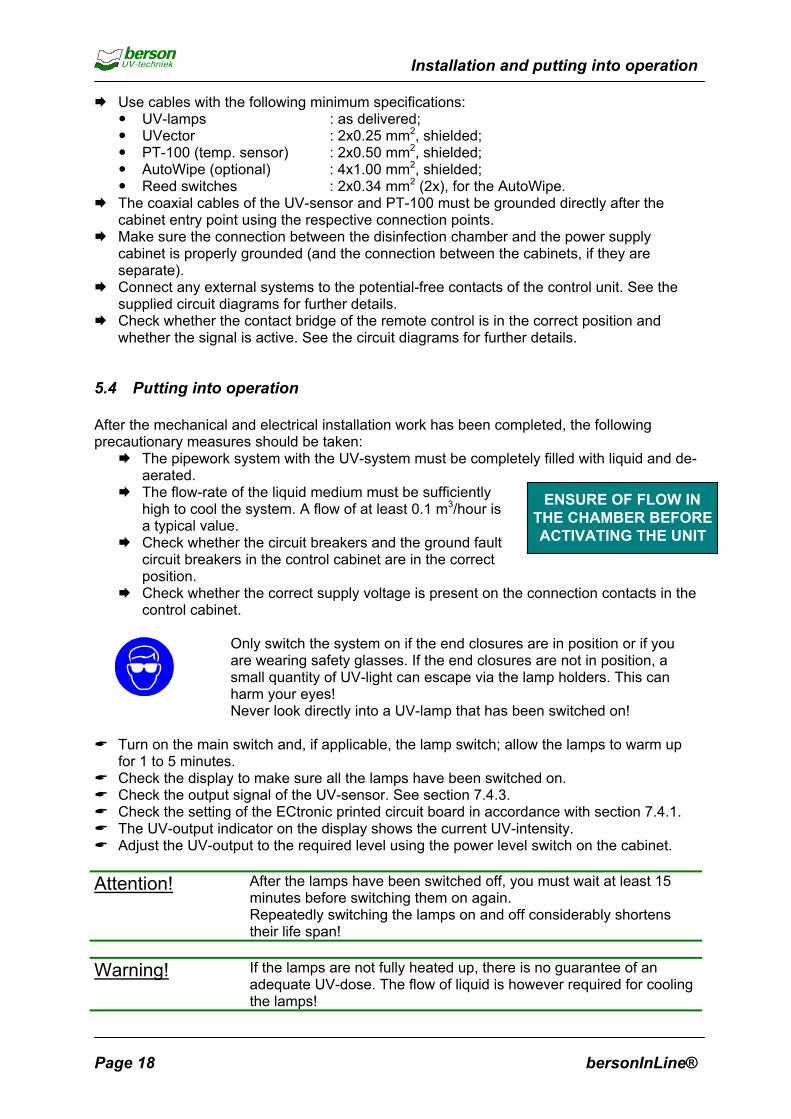
5.4 Putting into operation After the mechanical and electrical installation work has been completed, the following precautionary measures should be taken:
The pipework system with the UV-system must be completely filled with liquid and de-aerated. The flow-rate of the liquid medium must be sufficiently
high to cool the system. A flow of at least 0.1 m3/hour is a typical value.
ENSURE OF FLOW INTHE CHAMBER BEFOREACTIVATING THE UNIT Check whether the circuit breakers and the ground fault
circuit breakers in the control cabinet are in the correct position. Check whether the correct supply voltage is present on the connection contacts in the
control cabinet.
Only switch the system on if the end closures are in position or if you are wearing safety glasses. If the end closures are not in position, a small quantity of UV-light can escape via the lamp holders. This can harm your eyes! Never look directly into a UV-lamp that has been switched on!
Turn on the main switch and, if applicable, the lamp switch; allow the lamps to warm up
for 1 to 5 minutes. Check the display to make sure all the lamps have been switched on. Check the output signal of the UV-sensor. See section 7.4.3. Check the setting of the ECtronic printed circuit board in accordance with section 7.4.1. The UV-output indicator on the display shows the current UV-intensity. Adjust the UV-output to the required level using the power level switch on the cabinet.
Attention! After the lamps have been switched off, you must wait at least 15
minutes before switching them on again. Repeatedly switching the lamps on and off considerably shortens their life span!
Warning! If the lamps are not fully heated up, there is no guarantee of an
adequate UV-dose. The flow of liquid is however required for cooling the lamps!
Page 18 bersonInLine®
Operation
6 Operation The bersonInLine® UV-system is extremely easy to operate. The way in which it works is described below:
6.1 General Make sure that the pipework system is completely filled with liquid and that the flow rate is sufficiently high. Turn the system on using the main switch or the lamp switch (if present). The lamps
immediately start working and reach the correct output level after 1 to 5 minutes. Optional: Adjust the lamp power to the required UV-intensity using the power level switch
on the cabinet. Change the setting as soon as the UV-intensity decreases. If necessary, turn the system off using the main switch.
6.2 Manual cleaning system (optional) Manual cleaning can take place while the system is operating. The required cleaning frequency depends on the medium and the UV-intensity given on the display. Remove the locking pin.
Warning! By removing the locking pin the handle of the wipe unit can
be pressed forcefully to the outside by the pressure in the chamber!
Pull the wiper system completely out with the handle or handgrip and then push it back in
again. If necessary, repeat this action several times. Replace the locking pin.
6.3 Automatic cleaning system (optional) Automatic cleaning takes place at set intervals during the normal operation of the UV-system. The way in which the interval time is set is described paragraph 7.4.2. One can also activate an immediate wipe by means of the control panel (see paragraph 4.3.3).
bersonInLine® Page 19

Checks, maintenance, repairs and settings
7 Checks, maintenance, repairs and settings
7.1 Checks Every day, the following points on the display have to be checked: The status of the UV-intensity. If the value is too
low: Clean the quartz sleeves, or Set the (optional) power level switch to a higher
value. UV-Alarm. If this LED lights up: Clean the quartz sleeves, or Set the (optional) power level switch to a higher
value, or Replace defective lamps (check the lamp
indicators on the display), or Replace all lamps because of their age. See
the instructions in paragraph 7.2.7. Check the composition of the liquid.
Water Temperature Alarm. If this LED lights up, the flomedium is stationary and the system will shut down. Cabinet Temperature Alarm. If this LED lights up, the
cabinet is approximately 158°F and the system will sh Check whether the cabinet ventilators are obstruct Clean the cabinet ventilator dust filters.
Cabinet Temperature Warning: If this LED lights up thcabinet is approximately 140°F and the system is in da Check whether the cabinet ventilators are obstruct Clean the cabinet ventilator dust filters.
Tip Note all relevant changes, settings and other actio
the logbook which is supplied with the product-spedocumentation.
Page 20
POWER ON
UV ALARM
WATER TEMP. ALARM
CABINET TEMP. ALARM
CABINET TEMP. WARNING
100 %
90 %
80 %
70 % ALARM
UV LAMP 2
UV LAMP 4
UV LAMP 6
UV LAMP 8
UV LAMP 10
UV LAMP 12
UV LAMP 1
UV LAMP 3
UV LAMP 5
UV LAMP 7
UV LAMP 9
UV LAMP 11
UV-OUTPUT
w rate of the liquid is too low or the
temperature in the power supply ut down. ed.
e temperature in the power supply nger of shutting down.
ed.
ns which have been carried out in cification part of this
bersonInLine®

Checks, maintenance, repairs and settings
7.2 Maintenance
7.2.1 Cleaning the quartz sleeves The quartz sleeves have to be cleaned on a regular basis. The optimum frequency for doing this depends on the medium and has to be established on the basis of on-hand experience working with the system. If the optional cleaning mechanism is used, cleaning can take place while the system is operating. If there is no cleaning mechanism, one of the following methods has to be used: Chemical cleaning: Turn off the liquid flow and the main switch of the UV-system. Place appropriate chemicals in the disinfection chamber via an external connection. Drain the liquid off via the drain plug or the (optional) solenoid valve after the time the
chemicals need to work has elapsed. Remember to remove the ventilation plug before draining. Rinse the disinfection chamber with the normal liquid medium used in the system, and
drain once again via the drain hole. Replace the drain and ventilation plugs.
Manual cleaning: Warning! Turn the main switch off and
disengage the automatic fuses in the power supply cabinet! Turn off the flow and drain the liquid. Remember that the lamps can be hot!
Attention! Wear clean cotton gloves to avoid damaging the
lamps.
Loosen the cable glands on the hood and remove it. Disassemble the end closure on the other side of the disinfection chamber as well. For InLine-20, -50, -125 and –200: Remove the lamp holders on the side where the
lamps have to be taken out of the disinfection chamber. Then remove the lamps from the quartz sleeves. For the other versions: remove the lamps as described in section 7.2.8. Disassemble the threaded bushes at both ends of the quartz sleeves with the supplied
spanner. Take the quartz sleeves carefully out. Use the black mandrel to press the sleeves out of
the end plates (the cylindrical part of the mandrel has to be pushed into the end of the sleeve).
Threaded bush
End plate
Quartz sleeve
Clean the sleeves with alcohol or replace them. Place the sleeves (without sealing rings) back in
the disinfection chamber. Use a new set of seals and place them in the
following way: Make the (black) O-ring wet with clean water
and slide it over the end of the sleeve. Slide the white support ring over the sleeve. Place the threaded bush over the end of the
quartz sleeve and tighten it by hand into the
bersonInLine® Page 21

Checks, maintenance, repairs and settings
end plate. Assemble the O-ring and the support ring on the other side of the disinfection
chamber. Fasten the threaded bush using the supplied fitting and a ring spanner (hand tight) so
that the O-rings push against the collar in the end plate. The sleeves must never be subjected to excessive force!
Fill the disinfection chamber with liquid, increase the pressure to the normal working level and check the system for leaks. Now place the UV lamps in the quartz sleeves according to the detailed instructions in
section 7.2.7 and 7.2.8. Assemble the end closure. Switch the system back on.
7.2.2 UV-sensor and quartz probe If the system does not have an (optional) built-in cleaning mechanism, the quartz sleeve window will have to be cleaned chemically as described in paragraph 7.2.1, or by using the following manual method: Warning! Turn of the main switch and the circuit breakers in
the power supply cabinet! Turn of the flow and drain the liquid in the disinfection chamber.
Loosen the connector on the top-side of the sensor. Unscrew the sensor by hand. Use a hook spanner to remove the NW25 ring nut. Take the probe of the sensor out of the chamber. Remove the locking nut using a (15mm) open-end
spanner. Take the quartz pen out, then clean it and the sealing
rings with alcohol. Assemble the parts in reverse order. In the adjacent
photo the parts are shown in the correct order. Use new seals if necessary. Switch the system back on.
Attention! In the point of the sensor, there is an a
correct distance from the UV-lamp. Thposition in the factory and may not be
7.2.3 Ventilation of the control cabinet(s) Regularly check and, if necessary, replace the dust filters in th
Page 22
djusting screw for setting the is screw is set in the correct tightened or loosened!
e cabinet ventilators.
bersonInLine®

Checks, maintenance, repairs and settings
7.2.4 Ground fault circuit breaker check Every month check the ground fault circuit breaker to make sure it is working properly by pressing the test button. The system should shut down immediately.
7.2.5 Manually operated cleaning mechanism (optional) Several parts have to be replaced after approximately 7,000 wiper movements or at least 1x per year. The parts should be replaced as follows: Warning! Turn the main switch off and
disengage the circuit breakers in the power supply cabinet! Turn of the flow and drain the liquid. Remember that the lamps can be hot!
Attention! Wear clean cotton gloves to avoid damaging the
lamps.
Remove the lamps and the quartz sleeves as described in paragraph 7.2.1. Remove the end plate of the disinfection chamber. Remove the cleaning mechanism. Replace the wiper rings and the seal on the wiper shaft. Reassemble the parts, replace lamps and the quartz sleeves according to the
instructions in paragraph 7.2.1.
7.2.6 Automatic cleaning mechanism (optional) Several parts have to be replaced after approximately 7,000 wiper movements or at least 1x per year. The parts should be replaced as follows: Warning! Turn the main switch off and disengage
the circuit breakers in the power supply cabinet! Turn of the flow and drain the liquid. Remember that the lamps can be hot!
Attention! Wear clean cotton gloves to avoid damaging the
lamps.
Remove the end closure of the UV-system. Remove the nuts of the motor plate, then remove motor (4) together with motor plate (5). Take the lamps and the quartz sleeves out as described in paragraph 7.2.1. Remove the end plate of the disinfection chamber.
bersonInLine® Page 23

Checks, maintenance, repairs and settings
Take out the cleaning mechanism. Replace the wiper rings (1), the
seal on the threaded spindle (7) and the plastic threaded nut (3) if necessary. Disassemble the bearing casing
(6), remove the bearing and replace the seal. Reassemble the parts. Replace
the lamps and quartz sleeves according to the instructions in paragraph 7.2.1. Assemble the end closure.
7.2.7 Replacing the UV lamps for InLine- Attention! If the lamp located n
of a defect, it must bin the system. In thithe UV-measureme
Attention! See the ‘Detail Lam
lamps in the disinfeoptimum distribution
Warning! Turn the main s
disengage the apower supply ca Turn off the flow Remember that
hot! Attention! Wear clean cott
lamps.
1. UV-lamps are supplied in cardboard packaging that includes a cleaning cloth and instructions.
2. Do not toyour bare h
2 1 4 5 3 6 7
Page 24
20, -50, -125 and -200
earest the UV-sensor has to be replaced because e replaced with a lamp that is already being used
s way, lamps with differing outputs will least affect nt.
p Configurations’ diagram for the position of the ction chamber. This is important in obtaining an of the UV-illumination in the liquid flow.
witch off and utomatic fuses in the binet! and drain the liquid.
the lamps can be
on gloves to avoid damaging the
uch the lamps with ands!
3.sid
Do not hold the lamps on one e.
bersonInLine®

Checks, maintenance, repairs and settings
4O
7renthla 1qcd
A
b
. Wear gloves. nly hold the lamp at the ends.
5. su
. Make sure that the lamp mains free of the large lock
ut. Pay particular attention to ickening in the middle of the mp.
8. sle
0. Place the lamp holder in the uartz sleeve, keep the onnector screw facing ownwards.
11bobalammi
ttention! The adjacehas to be pconnector scondensati
ersonInLine®
Clean the glass with the pplied cloth.
6. quke
Push the lamp as far into the eve as shown in the photo.
9. cathewh
. Slide the lamp holder over th threaded ends, until the ck of the lamp is secure in the p holder. Only apply
nimum force!
12whTigMatou
nt pictogram indicates that the lalaced in the quartz sleeve with tcrew facing downwards (becau
on).
Slide the lamp carefully into the artz sleeve. The lamp must be pt on a straight horizontal line!
Position the lamp holder refully and cleanly in line with lamp; hold the lamp steady ile doing so.
hs
. Release the lamp holder, ich will spring back slightly. hten the M4 nuts by hand. ke sure that the lamp is not ching anything.
mp holder e e of
- -
++
Page 25

Checks, maintenance, repairs and settings
7.2.8 Replacing the UV lamps for other InLine types Attention! If the lamp located nearest the UV-sensor has to be replaced because
of a defect, it must be replaced with a lamp that is already being used in the system. In this way, lamps with differing outputs will least affect the UV-measurement.
Attention! See the ‘Detail Lamp Configurations’ diagram for the position of the
lamps in the disinfection chamber. This is important in obtaining an optimum distribution of the UV-illumination in the liquid flow.
Warning! Turn the main switch off and
disengage the automatic fuses in the power supply cabinet! Turn off the flow and drain the liquid. Remember that the lamps can be
hot!
Attention! Wear clean cotton gloves to avoid damaging the
lamps.
1. Remove the black cover plate on both sides.
2. Loosen the retaining nuts of the sealing cover on the non-service side (see mech. drawings) so that the lamp connections are accessible.
3. Remove the lamp holder plate (2 M4 nuts) and loosen the lamp wire of the wiring connector.
4. Remove also the lamp holder plate on the service side.
5. Loosen the lamp wire of the wiring connector. Take the old lamp out of the quartz sleeve, together with the two glass tubes.
6. Ncarwitins
Page 26
ew UV lamps are supplied in dboard packaging, together h cleaning cloth and tructions.
bersonInLine®

Checks, maintenance, repairs and settings
7. ba
10clo
13thesliseus
7. Fo
be
Do not touch the lamp with re hands!
8. sid
. Clean the glass with the th supplied.
11theexMatubthelen
. To keep the lamp in position lamp holder plate must be
d over the wire ends and cured with the M4 nuts. Do not e any tools for this!
14agag
2.9 Replacing the quartz sleev
r replacing the quartz sleeves,
rsonInLine®
Do not hold the lamp on one e.
9. WOn
. Slide the lamp carefully into quartz sleeve. Hold the lamp
actly horizontal! ke sure that the two glass es do not get mixed up as re may be a difference in gth.
12.thewiraccThethe
. Slide the sealing cover ainst the disinfection chamber ain and tighten the nuts.
15.notring
es
see the instructions in paragraph
ear clean cotton gloves. ly hold the lamp at the ends.
First connect the lamp wire on non-service side, so that the ing connector is easily essible. n connect the lamp wire on
service side.
Fit the two cover plates. Do forget to attach the two plastic s.
7.2.1: Manual cleaning.
Page 27

Checks, maintenance, repairs and settings
7.3 Repairs
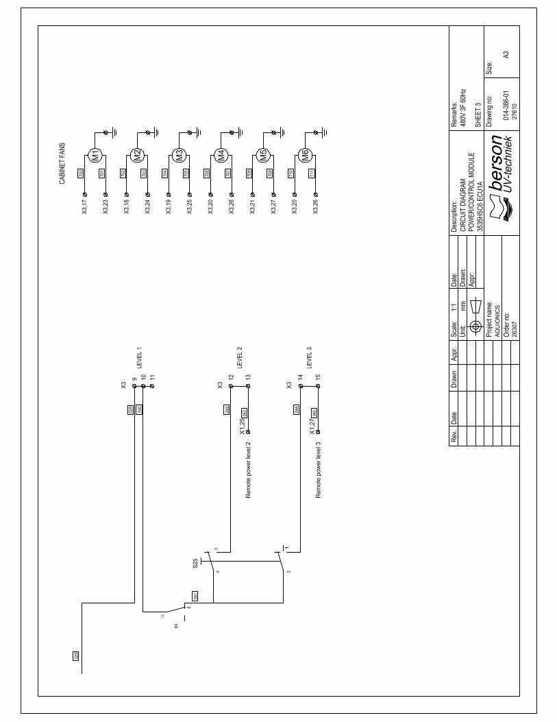
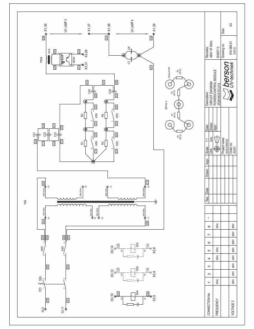
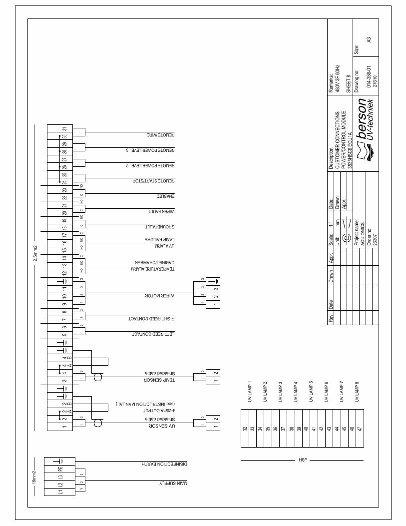
7.3.1 Explanation of the circuit diagrams The circuit diagrams consist of several sheets with columns that are numbered as follows: Sheet 1: columns 0 – 19, Sheet 2: columns 20 – 39 etc. The components are numbered with an alphanumeric character followed by the column number. Applied component characters: C Capacitor F Fuse H Hours counter K Relay M Motor, ventilator P Pulse counter R Resistor S Switch SD Lamp current detector T Bimetal switch Tr Transformer U Power supply unit V LED, Diode, Transistor X Connection, cable sleeve For relays, the diagrams contain tables listing the relay contacts. The number indicates the column in which the contact is used (NC = normally closed and NO = normally opened). Colour coding for the wiring: Black Connection voltage (phase) Blue (Low voltage) direct current or zero voltage Red (Low voltage) alternating current Green-yellow Ground White Potential-free External connections of the control cabinet (when using the ECtronic): Use Explanation Remote on-off If these contacts are closed, the system will start up. Water temperature alarm When the alarm is activated, the potential free two-way contact
is switched over. Cabinet temperature alarm When the alarm is activated, the potential free two-way contact
is switched over. UV alarm When the alarm is activated, the potential free two-way contact
is switched over.
Page 28 bersonInLine®

Checks, maintenance, repairs and settings
Ground fault If the ground fault circuit breaker is activated, the potential
free two-way contact is switched over. Cleaning-alarm If a problem occurs in the automatic cleaning mechanism,
the potential free two-way contact is switched over. Solenoid valve 230V AC has to be connected to these contacts to switch
the solenoid valve on and off. UV-signal The output current of the UV-sensor from these contacts
can be used for measuring purposes. A galvanic isolation is recommended.
7.3.2 Troubleshooting the (optional) automatic cleaning mechanism If the mechanism is not functioning, check the working of the reed contacts with an external magnet. Also make sure the interval between cleaning is longer than 10 minutes to prevent overloading the motor. If the motor shuts down due to overheating, it has to be allowed to cool down before being switched back on again. Note that the wiper fail alarm can only be cleared by powering down the unit.
7.3.3 Malfunctions to the temperature sensor The temperature of the liquid is continuously measured by the control system to avoid overheating of the UV-lamps. If it is suspected that the temperature sensor (PT100) is defective, the correct functioning of the sensor can be checked by measuring a current value on the control printed circuit board (only for the ECtronic control system). Measure the liquid temperature using an external thermometer. Connect an ammeter in accordance with the diagram below and check whether the measured current agrees with the value in the table. The value may deviate by a maximum of 0.15 mA.
Temp [°F] Current [mA]
32 4.00 41 4.76 50 5.53 59 6.30 68 7.07 77 7.84 86 8.61 95 9.38
104 10.15 113 10.92 122 11.69 131 12.46 140 13.23 149 14.00 158 14.76 167 15.53 176 16.30 185 17.07 194 17.84
A Cable connectors: 17-18
PT100 Ammeter
bersonInLine® Page 29

Checks, maintenance, repairs and settings
7.3.4 Other troubleshooting The UV-Alarm is active, but the lamps and quartz sleeves are in proper working order: Check the liquid.
The UV-lamps do not switch on: Check whether the ground fault or the circuit breakers have dropped out. Check whether the contact bridge of the remote control is in the correct position and
whether the signal is active. See the circuit diagrams for further details. If there are any other problems, contact the service department of Berson UV-techniek.
Page 30 bersonInLine®

Checks, maintenance, repairs and settings
7.4 Settings
7.4.1 Calibration of the display of the UV output The settings on the ECtronic printed circuit board are dependent on the T10-value and volume of flow of the liquid. The setting is made at the factory, but should be made again when putting into operation. Follow the procedure below to do this: Calculate the following quantities: Quantity Unit Description UV-C [mJ/cm2] This is the required UV-C dose. It depends on the nature of the
liquid medium *. Flow-cap [m3/hour] This is the flow capacity of the system with UV-transmission T10.
See the capacity table in the annex and calculate the ‘Flow capacity’ for the specific T10-value*.
Norm-flow [m3/hour] This is the normal quantity of liquid that has to be disinfected. If this is not always constant, take the maximum value.
* If any of these quantities are unknown, contact Berson UV-techniek. Calculate the UV-output value using the following formula (example):
25 [mJ/cm2] Flow-cap UV-output = X X 100%
UV-C Norm-flow The correct setting must now be made on the ECtronic printed circuit board using the value calculated with the above formula.
Work out the necessary target value from the table below: UV-output Target value 100 % 6.30 V 94 % 6.00 V 88 % 5.70 V 85 % 5.55 V 78 % 5.40 V 75 % 5.10 V 70 % 4.80 V 63 % 4.50 V 57 % 4.20 V Calculate if necessary the interim target Connect a voltmeter to terminals 26 (-) apotentiometer P1 until the measured valuthe table. Warning! Remember that th
bersonInLine®
value or the target value above 100%. nd 41 (+) of the printed circuit board. Then adjust the e corresponds with the appropriate target value in
e supply voltage is switched on!
Page 31

Checks, maintenance, repairs and settings
7.4.2 Interval time of the (optional) automatic cleaning mechanism The interval time for automatic cleaning can be adjusted on the EC-Wipe printed circuit board via contact bridge (X1) and a trimming potentiometer (P1). Range of the trimming potentiometer: • Contact bridge present : 2 hours – 24 hours. • Contact bridge absent : 10 min. – 120 min. Turning the trimming potentiometer clockwise increases the interval time. The factory setting is approximately 1 hour.
7.4.3 Checking the UV sensor when putting into operation and after 100 hours of use The UV dose of the lamps is stabilised after about 100 hours of use. After this period the measurement value of the UV sensor should therefore be set again. This applies also 100 hours after all lamps have been replaced due to their age, but also when the system is first put into use.
P1
X1
Make sure that the UV system is working normally. Check that the T10 value (T10 actual) of the liquid is the same as the T10 value in the technical specifications supplied (T10 spec). If this is not the case, calculate the required sensor current as follows:
T10-actual
UV-signal = X 7,5 + 4 [mA] T10-spec
If the actual T10 value does not differ from the specification value, the sensor current should be 11.5 mA. Measure the output current of the UV sensor, as shown in the diagram on the next page. Remove the plug from the UV sensor (see photograph). Correct the position of the trimming potentiometer behind the plug, so that the output current (Iuv) corresponds with the value just determined. Fit the plug again.
Page 32 bersonInLine®

Checks, maintenance, repairs and settings
Measuring the output current of the UV-Sensor:
be
A
Cable connectors: 14-15
UV-sensor Ammeter
rsonInLine® Page 33

Spare parts and disposal
8 Spare parts See the annex, for a list of spare parts. 9 Disposal
9.1 General If the UV-system is no longer used and has to be disassembled, the following steps should be carried out: Ensure that the liquid flow has been shut down and that the entire pipework system is
empty. Ensure that the control cabinet and operating console have been disconnected. Remove the electricity mains connections (plugs) and remove the plugs from the cables. Disassemble the disinfection chamber, remove the UV-lamps carefully according to the
instructions of paragraph 7.2.1. Dispose of the lamps according to local regulations or send them
back to Berson UV-techniek. Disassemble the system further working from top to bottom. Use
appropriate tools for this and observe safety procedures! The disinfection chamber and the control cabinet must be disposed
of in accordance with local regulations; preferably by sending them to a company that can recycle the materials.
Attention: These points only apply to parts supplied by Berson UV-techniek and descthis manual.
9.2 Returning old lamps Used lamps can be returned to Berson UV-techniek. To do this, ask for thenumber” beforehand.
Page 34
ribed as such in
required “RMA
bersonInLine®

Specifications
Annex bersonInLine®
Customer AQUIONICS INC.
21 KENTON LANDS RD ERLANGER, KY 41018 U.S.A.
Specifications: Type number : InLine 4250 spc Article number : 1HZS06WRUE*3 Series number : 7906 Berson order number : 27610 Year of construction : 2002 Area of use : Ballast Water Flow capacity [m3/hr] : 487 Transmission value T10 [%] : 65 Nominal liquid temperature [°C] : - Nominal work pressure [Bar] : 10 UV-C value [mJ/cm2] : 25 Electrical configuration [V, Hz, phases] : 480V, 60, 3F Material disinfection chamber : SS316L Connecting flanges : none Quartz tubes : F200 Lamp type : B3535H Cleaning mechanism : Automatic Control system : EC-Tronic UV-detection : UVector Power adjustment : Manual Diagrams: Power/Control Module : 014-386-01 Layout : Component View : Wiring Diagrams : Wiring Charts : Layout Inline 4250 Special : 040-088-01 UV-Lamp Positions : 040-032-01 PT100 Probe : 003-129-01 UVector : 003-123-01 Quartz Probe : 003-130-01 Automatic Wiper Mechanism : 004-267-01 Wire Lamp Detail : 003-195-01 Air Bleed Taps : 045-106-01 Supplemental: Step-Down Transformer EDB 168920

Specifications
Annex bersonInLine®
Recommended spare parts:
Attention: The recommendations for spare parts are only valid for a year. Only use original Berson parts. All guarantees and liability will expire if other parts are used than those specified by Berson UV-techniek.
Part No. Description no wiper hand wipe auto wipe no wiper hand wipe auto wipe no wiper hand wipe auto wipe0.43.101 Fan Filter 1 1 12.11.384 Ball bearing 26*9*8 12.11.385 Circlip 12.11.165 Splitpen 32*4 22.21.315 Boss for trapezium spindle 12.21.316 Boss for trapezium spindle 12.58.090 Cleaning wiper ring 6 62.43-190 UV-lamp B3535H 6 6 6 1 1 12.55.013 Quartz sleeve 867mm F200 6 6 6 1 1 12.56.299 Seal 15*25*8 (hand wiper) 1 12.56.301 Seal 10*25*10 (auto wiper) 22.56.124 O-ring 32*5 (q-sleeve) 12 12 122.56.105 O-ring 20*3 (T-stop) 2 1 12.56.200 O-ring NW25 1 1 12.56.024 O-ring 10*4 (sensor) 1 1 12.58.015 O-ring 15*3 (pt100 - 1/2"plug) 2 2 22.56.141 O-ring 365*6 2 2 2
EVERY THIRD YEAR SECURITY STOCKEVERY YEAR
BERSON UV-DISINFECTION UNIT RECOMMENDED SPARES
INLINE 4250

Specifications
Annex bersonInLine®
Capacity table: The adjacent table is important in adjusting the UV-sensor.
UV-dosage = 25mJ/cm2 at end of lamp life
Transmission over 10mm
(%)
Flow capacity
(m3/h) 100 4509 98 3599 96 2930 94 2429 92 2047 90 1750 88 1516 86 1327 84 1174 82 1047 80 940 78 849 76 771 74 704 72 645 70 593 68 547 66 506 64 469 62 436 60 406