Embed Size (px)
Citation preview

8.2.1 Edition 08.10DK S N P GR
� www.docuthek.comD GB F NL I E
TR CZ PL RUS H
© 2008 – 2009 Elster GmbH
Please read and keep in a safe place
Please read through these instructions carefully before installing or operating. Follow-ing the installation, pass the instructions on to the operator. These instructions can also be found at www.docuthek.com.
Explanation of symbols • , 1 , 2 , ... = Action▷ = Instruction
LiabilityWe will not be held liable for damages resulting from non-observance of the instructions and non-compliant use.
Safety instructionsInformation that is relevant for safety is indicated in the instructions as follows:
DANGERIndicates potentially fatal situations.
WARNINGIndicates possible danger to life and limb.
CAUTIONIndicates possible material damage.
All interventions may only be carried out by qualified gas technicians. Electrical interventions may only be carried out by qualified electricians.
Conversion, spare partsAll technical changes are prohibited. Only use OEM spare parts.
TransportOn receipt of the product, check that the delivery is complete (see Part designations). Report any trans-port damage immediately.
StorageStore the product in a dry place. Ambient tempera-ture: see Technical data.
Operating instructions
Translation from the German
D GB F NL I E
GB-1
Safety
Contents
UV sensor UVS 10
UV sensor UVS 10 . . . . . . . . . . . . . . . . . . . . . . 1Contents . . . . . . . . . . . . . . . . . . . . . . . . . . . . . . 1Safety. . . . . . . . . . . . . . . . . . . . . . . . . . . . . . . . . 1Checking the usage . . . . . . . . . . . . . . . . . . . . . 2Type code. . . . . . . . . . . . . . . . . . . . . . . . . . . . . . 2Installation . . . . . . . . . . . . . . . . . . . . . . . . . . . . 2UVS 10 with internal thread adapter. . . . . . . . . . 2UVS 10 with UVS 1 adapter. . . . . . . . . . . . . . . . 3
Cable selection. . . . . . . . . . . . . . . . . . . . . . . . . Cable installation . . . . . . . . . . . . . . . . . . . . . . . Wiring . . . . . . . . . . . . . . . . . . . . . . . . . . . . . . . . UVS 10..G1 . . . . . . . . . . . . . . . . . . . . . . . . . . . . 3UVS 10..P2 . . . . . . . . . . . . . . . . . . . . . . . . . . . . 3
Maintenance . . . . . . . . . . . . . . . . . . . . . . . . . . . 4Replacing the UV tube . . . . . . . . . . . . . . . . . . . . 4Cleaning or replacing the quartz glass disc . . . . 4
Assistance in the event of malfunction . . . . . 4Accessories . . . . . . . . . . . . . . . . . . . . . . . . . . . 5Adapter UVS 1 with quartz glass disc . . . . . . . . 5Cooling air adapter with quartz glass disc . . . . . 5Quartz glass lens with seals . . . . . . . . . . . . . . . . 5
Technical data. . . . . . . . . . . . . . . . . . . . . . . . . . 6Contact . . . . . . . . . . . . . . . . . . . . . . . . . . . . . . . 6

GB-2
D GB F NL I E
Checking the usage
UVS 10UV sensor for flame control of gas burners, only in conjunction with Elster Kromschröder automatic burner control units IFS, IFD, PFS and PFD, flame detectors IFW or PFF or burner control units BCU or PFU.This function is only guaranteed when used within the specified limits – see also “Technical data”. Any other use is considered as non-compliant.
Type codeCode DescriptionUVS UV sensor10 Series 10DL
Quartz glass heat guardQuartz glass heat guard lens
01
2
4
Rp 1/2 internal threadRp 1/2 internal thread and cooling air
connection1/2 NPT internal thread
1/2 NPT internal thread and cooling air connection
UVS 1 Adapter (28 mm (1.1”))
G1P2
Electrical connectionM20 cable gland
4-pin plug, with socketPart designations
1
2
43
6
5
7 8
UVS 10..G1
UVS 10..P2
1 Housing2 Cable gland UV tube4 Adapter with quartz glass5 Plug6 Socket7 Retaining screw8 Seal
Installation
CAUTIONPlease observe the following to ensure that the UVS is not damaged during installation:– Use UV sensor only in conjunction with Elster
Kromschröder automatic burner control units, flame detectors or burner control units.
– Cool UV sensor with filtered air when subject to higher temperatures (see “Accessories”). In addition, this protects the sensor from dirt and condensation.
< 400 mm(16”)
Cooling air
▷▷ Max. distance between UVS and flame < 400 mm (16”).▷▷ It can be fitted using a ½” viewing tube that should
be aligned on the first flame third, as this is where the highest UV radiation is generally found. The inside of the steel tube should not be coated and the tube should be directed at the flame from above so that no dirt collects in front of the UV sensor.▷▷ The UVS..L with quartz glass lens must be pre-
cisely aligned with the flame.▷▷ The UV sensor may only be exposed to the UV
light of its own flame. It should be protected from other sources of ultraviolet light, e.g. neighbouring flames (this must be observed when monitor-ing pilot and main burners in particular), ignition sparks, arcs from welding devices or lamps emit-ting ultraviolet light.▷▷ Do not expose the UV sensor viewing opening
to direct sunlight.▷▷ Supply cooling air to cool and protect the optical
system from soiling and condensation.▷▷ Max. cable length in accordance with the speci-
fications for automatic burner control units IFS, PFS, PFD, flame detectors IFW, PFF or burner control units BCU, PFU.
UVS 10 with internal thread adapter
2 31

GB-3
D GB F NL I E
UVS 10 with UVS 1 adapter
21
Cable selection▷▷ Use mains cable suitable for the type of operation
and complying with local regulations.▷▷ Signal line ≤ 2.5 mm².▷▷ The cable gland on the UVS 10..G1 or on the
socket of the UVS 10..P2 is suitable for cable diameters of 7 to 13 mm.
Cable installation▷▷ Avoid external electrical interference.▷▷ Lay cables individually and, if possible, not in a
metal conduit.▷▷ Do not lay UV cable and ignition cable together
but lay them as far apart as possible.
Wiring
WARNINGElectric shocks can be fatal! Before working on possible live components ensure the unit is discon-nected from the power supply.
1 Disconnect the system from the electrical power supply.
2 Shut off the gas supply.
UVS 10..G1 Route the cables through the M20 cable gland. 4 Wire the UV sensor as shown in the wiring dia-
gram for the correctly selected automatic burner control unit, flame detector or burner control unit, including the PE wire.
1 2 3
UVS 10..P2
213
43
6 75
Wire the socket as shown in the wiring diagram for the correctly selected automatic burner control unit, flame detector or burner control unit, including the PE wire.

GB-4
D GB F NL I E
Maintenance
Replacing the UV tube▷▷ The UV tube in the UV sensor must be replaced
after approx. 10,000 operating hours (approx. 1 year) as its service life has expired (see “Ac-cessories”).
1 Disconnect the system from the electrical power supply.
2 Shut off the gas supply.▷▷ Do not touch the new UV tube with bare fingers.
4 5
6
3
7
Cleaning or replacing the quartz glass disc2 3
4
1
5 Follow the reverse procedure when reassembling.▷▷ For a quartz glass lens, ensure that the lens cur-
vature points towards the flame.
Assistance in the event of malfunction
WARNING– Electric shocks can be fatal! Before working
on possible live components ensure the unit is disconnected from the power supply!
– Fault-clearance must only be undertaken by authorised, trained personnel!
– Unauthorised repairs on the UV sensor will cancel our guarantee. Unauthorised repairs or incorrect electrical connections can cause the UV sensor to become defective. In this case fail-safe operation can no longer be guaranteed!
– (Remote) resets may only be conducted by au-thorised personnel with continuous monitoring of the burner to be repaired.
– Safe operation only in conjunction with Elster Kromschröder automatic burner control units, flame detectors or burner control units.
• Measure the current in the flame signal cable (con-nect the positive pole of the measuring instrument to the cable from the automatic burner control unit and the negative pole to the cable from the UV sensor).▷▷ The measured direct current must be greater than 1 µA (typically 20 µA).
UVS123
PE
– +µA
Signal
? Fault ! Cause • Remedy
Possible faults and suggested solutions ? A direct current is flowing, but no flame present. ! The UV sensor is influenced by the flames of other
burners, e.g. by reflection on the furnace walls. • Position the sensor so that it can only “view” its
own dedicated flame (e.g. use viewing tube). ! Humidity inside the sensor. • Vent sensor. ! The service life of the UV sensor has expired. • Replace UV tube in the UV sensor (see “Mainte-
nance”). ! The sensitivity of the flame amplifier in the auto-
matic burner control unit is too high. • Adjust switching threshold on automatic burner
control units with adjustable switch-off threshold.
Tighten the screw firmly.
GB-5
D GB F NL I E
? No direct current although the flame is burning. ! The UV sensor is dirty, e.g. sooted. • Clean sensor or quartz glass. ! Humidity inside the UV sensor. • Vent sensor. ! The distance between the UV sensor and the
flame is too great. • Reduce the distance.
? The automatic burner control unit ignites in pulses. ! The sensor “sees” the ignition spark. • Reposition the UV sensor so that it cannot “see”
the ignition spark. • Use an automatic burner control unit that is able
to distinguish between an ignition spark and a flame signal.
? The intensity of the flame signal decreases after a longer period of operation.
! UV tube fault due to incorrect UV sensor connec-tions.
• Remove the UV sensor and return for repair. • Connect the UV sensor in accordance with the
wiring instructions.
? The automatic burner control unit performs a fault lock-out during start-up or operation.
! The highly fluctuating flame signal temporarily exceeds the switch-off threshold.
• Reduce the distance between UV sensor and flame.
• Position the UV sensor so that it can “view” the flame without hindrance (e.g. smoke curtain).
• Replace quartz glass disc in the UV sensor with a lens (see “Accessories”).
! The switch-off threshold in the automatic burner control unit is set too high, e.g. BCU, PFU or IFD 258.
• Adjust switch-off threshold.
Accessories
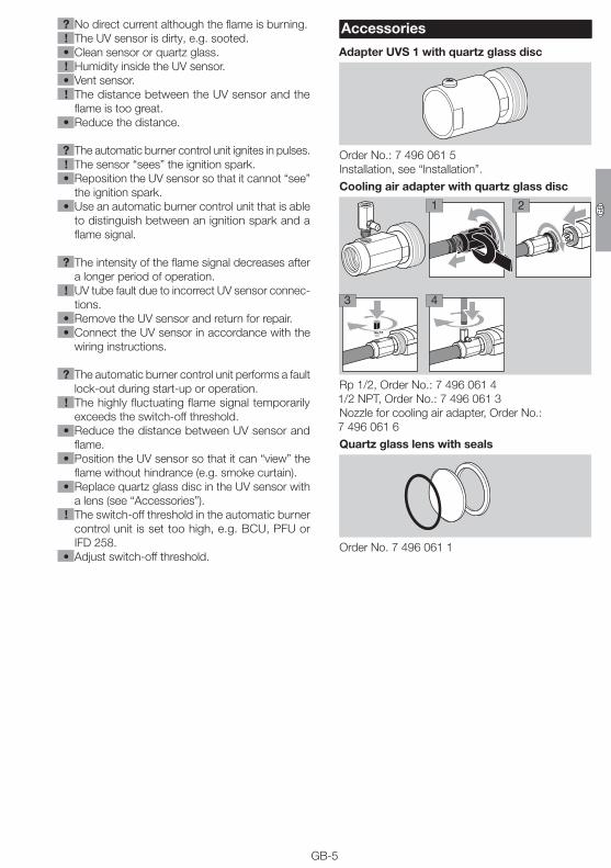
Adapter UVS 1 with quartz glass disc
Order No.: 7 496 061 5 Installation, see “Installation”.
Cooling air adapter with quartz glass disc
2
3 4
1
Rp 1/2, Order No.: 7 496 061 4 1/2 NPT, Order No.: 7 496 061 3Nozzle for cooling air adapter, Order No.: 7 496 061 6
Quartz glass lens with seals
Order No. 7 496 061 1

Elster GmbHPostfach 28 09, D-49018 OsnabrückStrotheweg 1, D-49504 Lotte (Büren)T +49 541 1214-0F +49 541 1214-370
GB-6
D GB F NL I E
If you have any technical questions, please contact your local branch office/agent. The addresses are available on the Internet or from Elster GmbH.
We reserve the right to make technical modifications in the interests of progress. [email protected], www.kromschroeder.com
Contact
Technical dataAluminium housing with integrated heat guard, with connection terminals.Clamping range of the connection terminals: ≤ 2.5 mm².Cable gland: for cable diameters of 7 to 13 mm.Distance between UV sensor and flame: 300 – 400 mm.UV tube: P578,spectral range: 190 – 270 nm,max. sensitivity: 210 nm ± 10 nm.Service life of the UV tube:approx. 10,000 operating hours.Min. DC signal: 1 μA.Enclosure: IP 65.Ambient temperature: -40 to +80°C (-40 to +176°F).Weight: 280 g (0.6 lbs).Max. length of cable UV sensor – automatic burner control unit: see instructions for automatic burner control unit.