Embed Size (px)
Citation preview
Utilizing the Internal Gyroscope for Reliable Inertial Navigation
Yusen Hu
Dulwich College Beijing
Utilizing the Internal Gyroscope for
Reliable Inertial Navigation
Abstract – This paper shows an approach on
how to significantly improve the maneuvering
reliability of a wallaby-controlled robot by
using its internal gyroscope and various
supporting algorithms. Stable movement is an
extremely desirable feature of robots in Botball,
because of the various obstacles present on the
game table, as well as possible interference
from the opponents, which can hit the robot and
set it off-course. A robot equipped with an
implementation of the gyroscope system can
accomplish tasks such as turning accurately for
90 degrees, driving in a straight line, and
correcting its orientation after colliding with
obstacles.
1. Introduction
Robots are typically constructed with two
motors on its base, each attached to two wheels,
that administers its movement around the game
table. The motors themselves are usually
controlled by functions such as mav( ) and
mrp( ), sometimes in conjunction with
correction methods such as line following, wall-
bumping, etc. This setup is widely used because
of its simplicity, but it has several drawbacks.
It is hard for the robot to move in a straight line,
even if the robot is oriented correctly at the
start, and the two motors are set to the same
velocity. This is because the two motors may
have a very slight speed differential, and one
wheel would spin faster than the other, causing
the robot to deviate left or right. Normally, with
some help from line-following and other
correction procedures, this problem can be
overcome, but sometimes it is necessary for a
robot to enter an area that has no lines to follow,
in which the conventional methods of
navigation would become too unreliable to use.
Accurate turning is also difficult to accomplish
by using this simple system, and sometimes a
significant deviation would appear if you
execute many seemingly perfect 90 degrees
turns in series. Using the mrp( ) function can
slightly improve the situation, but the back-
EMF based tick counting system for the motors
still suffers from precision issues, and its
readings varies for different motors.
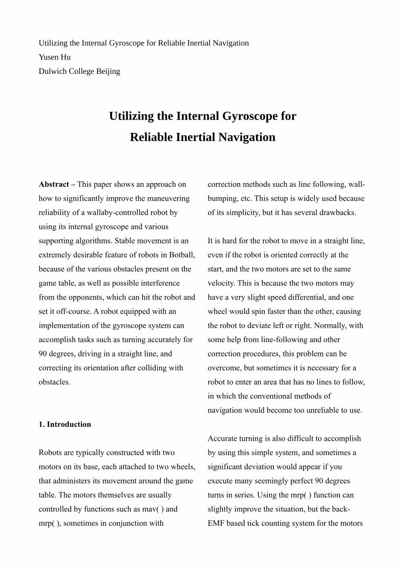
The presence of obstacles on the game table
poses a further threat to the robots. Most of the
time, a properly installed bumper can push away
dangers in the robot’s way, but sometimes,
deformable objects, such as pom balls, can be
squashed and slide under the bumper. The wheel
would slip if a pom goes beneath it, and this
causes the robot to deviate off course.
Interference from the opposing team can also
similarly affect the robot’s movement.
The problems mentioned above inspired the
author of this paper to develop the gyroscope-
based inertial navigation system to improve the
robot’s reliability and stability.
2. Data Stabilization
Ideally, the readings from the gyroscope on all
axis should be zero when the robot is static.
However, this is rarely the case, because the
gyroscope is affected by vibrations, ambient
temperature, and various other uncontrollable
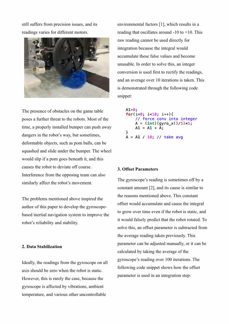
environmental factors [1], which results in a
reading that oscillates around -10 to +10. This
raw reading cannot be used directly for
integration because the integral would
accumulate these false values and become
unusable. In order to solve this, an integer
conversion is used first to rectify the readings,
and an average over 10 iterations is taken. This
is demonstrated through the following code
snippet:
3. Offset Parameters
The gyroscope’s reading is sometimes off by a
constant amount [2], and its cause is similar to
the reasons mentioned above. This constant
offset would accumulate and cause the integral
to grow over time even if the robot is static, and
it would falsely predict that the robot rotated. To
solve this, an offset parameter is subtracted from
the average reading taken previously. This
parameter can be adjusted manually, or it can be
calculated by taking the average of the
gyroscope’s reading over 100 iterations. The
following code snippet shows how the offset
parameter is used in an integration step:
A different offset parameter is used for
calculating the degrees turned when the robot
rotates. In order to ease the programming
process, we multiply the target angle by the
offset, and compare this value to the one
returned by the integral, as the integral uses an
arbitrary unit that isn’t degrees. This way,
instead of passing an arbitrary value into the
function, we can now simply write rotate(90) to
turn 90 degrees. The angle_f offset parameter is
tuned manually by seeing if the robot can return
to its original orientation by rotating 720
degrees, using a series of rotate(90) calls. This
process accumulates the small deviation in each
rotation that would otherwise be unnoticeable.
A third offset parameter is used to account for
the reading difference returned by the gyroscope
for clockwise and counterclockwise rotations.
This difference was discovered by accident
when the author observed that a perfectly
calibrated clockwise 90 degrees turn will always
result in a constant amount of excess rotation
when -90 (anticlockwise turn) is passed to the
rotation function. This negative offset is
calibrated manually, with the same procedure
(rotate 720 degrees and observe the deviation)
that’s used previously.
The value of nrOffset is typically set to 0.99
based on the author’s experience, but may need
to be adjusted for different wallaby controllers.
4. Fixed Time Step Integration
Integration is the central component in the
gyroscope navigation system. To calculate
displacement over a period of time, the
following integral is used [3]:
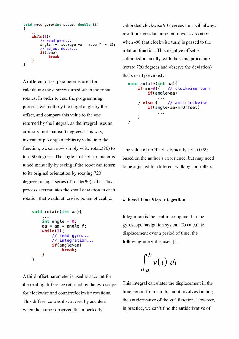
This integral calculates the displacement in the
time period from a to b, and it involves finding
the antiderivative of the v(t) function. However,
in practice, we can’t find the antiderivative of
the gyro_x( ) function, so it is usually
implemented as a finite sum to approximate the
integral, with Δt being a finitely small value,
typically 1 millisecond:
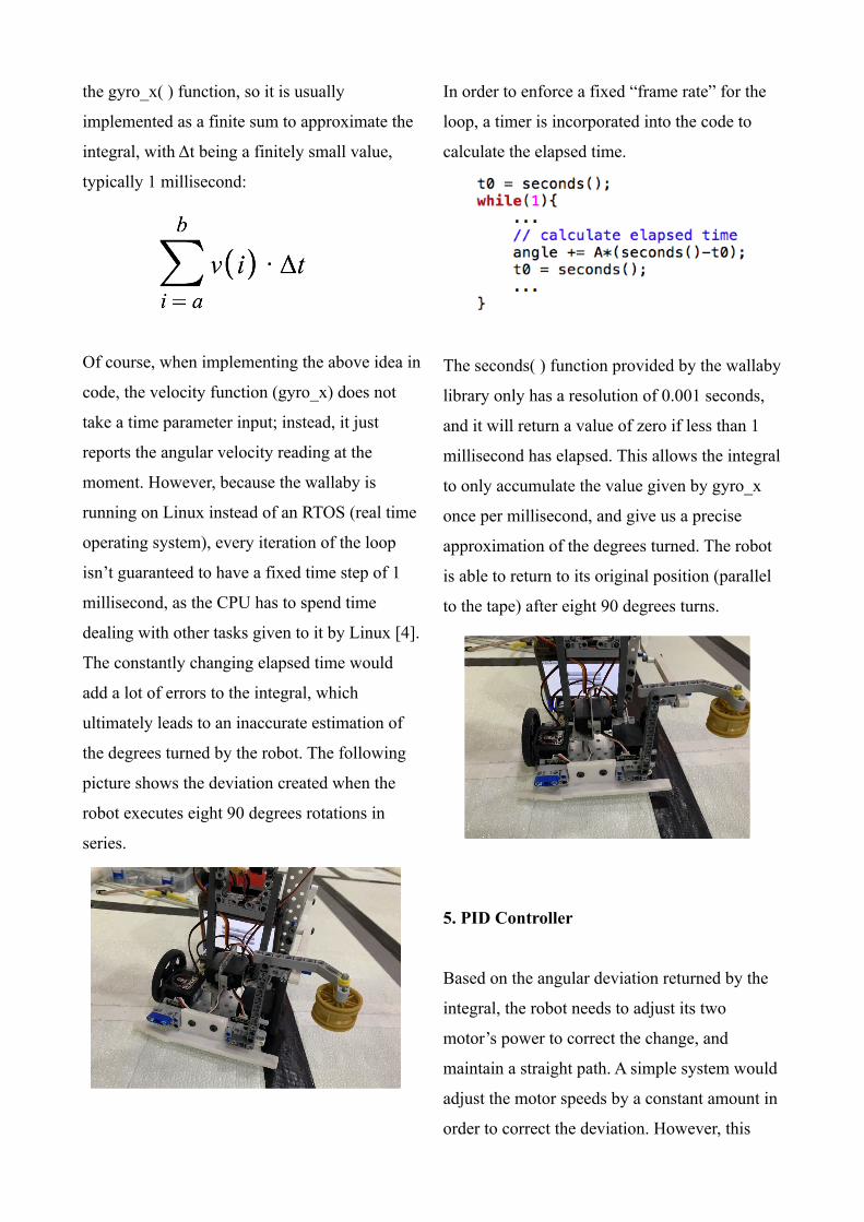
Of course, when implementing the above idea in
code, the velocity function (gyro_x) does not
take a time parameter input; instead, it just
reports the angular velocity reading at the
moment. However, because the wallaby is
running on Linux instead of an RTOS (real time
operating system), every iteration of the loop
isn’t guaranteed to have a fixed time step of 1
millisecond, as the CPU has to spend time
dealing with other tasks given to it by Linux [4].
The constantly changing elapsed time would
add a lot of errors to the integral, which
ultimately leads to an inaccurate estimation of
the degrees turned by the robot. The following
picture shows the deviation created when the
robot executes eight 90 degrees rotations in
series.
In order to enforce a fixed “frame rate” for the
loop, a timer is incorporated into the code to
calculate the elapsed time.
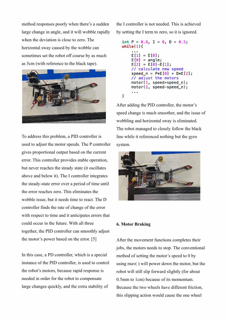
The seconds( ) function provided by the wallaby
library only has a resolution of 0.001 seconds,
and it will return a value of zero if less than 1
millisecond has elapsed. This allows the integral
to only accumulate the value given by gyro_x
once per millisecond, and give us a precise
approximation of the degrees turned. The robot
is able to return to its original position (parallel
to the tape) after eight 90 degrees turns.
5. PID Controller
Based on the angular deviation returned by the
integral, the robot needs to adjust its two
motor’s power to correct the change, and
maintain a straight path. A simple system would
adjust the motor speeds by a constant amount in
order to correct the deviation. However, this
method responses poorly when there’s a sudden
large change in angle, and it will wobble rapidly
when the deviation is close to zero. The
horizontal sway caused by the wobble can
sometimes set the robot off course by as much
as 5cm (with reference to the black tape).
To address this problem, a PID controller is
used to adjust the motor speeds. The P controller
gives proportional output based on the current
error. This controller provides stable operation,
but never reaches the steady state (it oscillates
above and below it). The I controller integrates
the steady-state error over a period of time until
the error reaches zero. This eliminates the
wobble issue, but it needs time to react. The D
controller finds the rate of change of the error
with respect to time and it anticipates errors that
could occur in the future. With all three
together, the PID controller can smoothly adjust
the motor’s power based on the error. [5]
In this case, a PD controller, which is a special
instance of the PID controller, is used to control
the robot’s motors, because rapid response is
needed in order for the robot to compensate
large changes quickly, and the extra stability of
the I controller is not needed. This is achieved
by setting the I term to zero, so it is ignored.
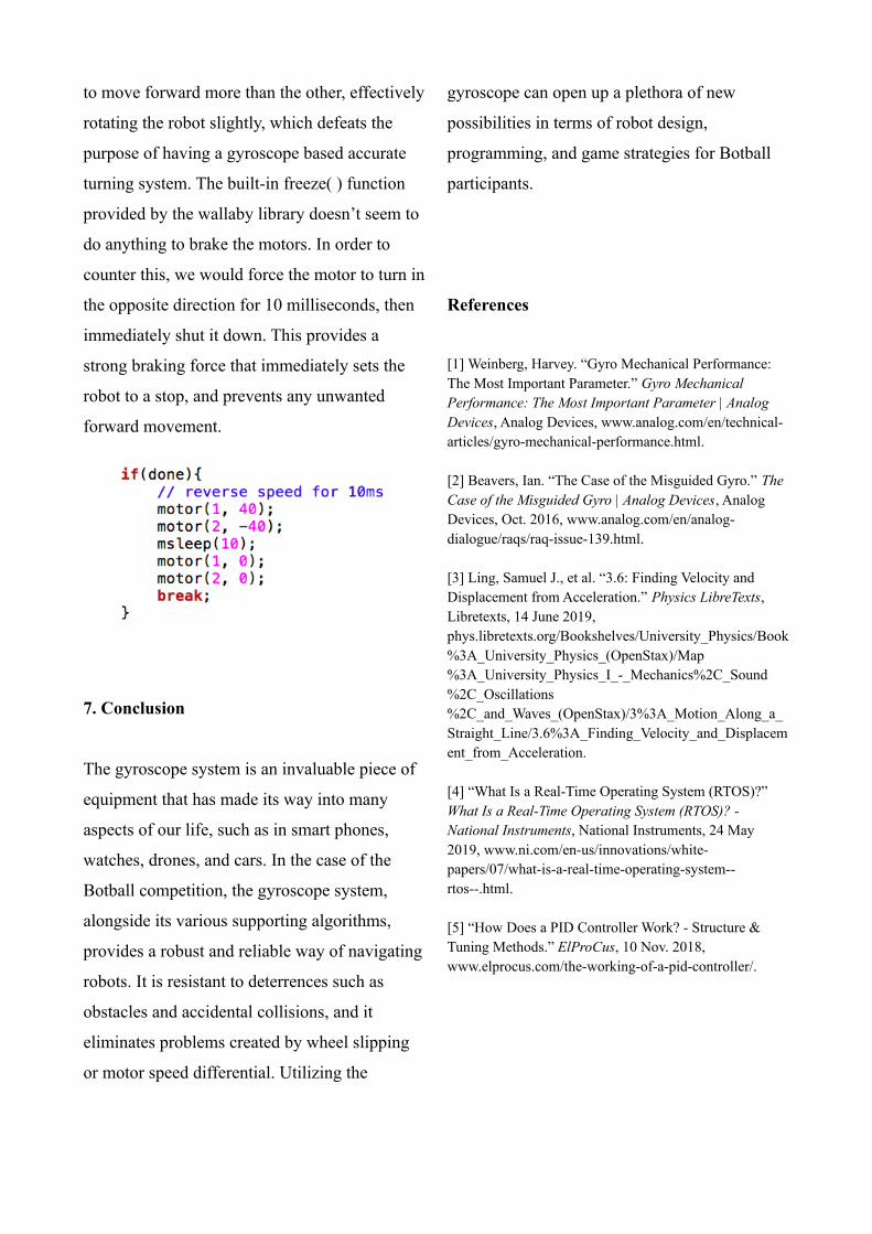
After adding the PID controller, the motor’s
speed change is much smoother, and the issue of
wobbling and horizontal sway is eliminated.
The robot managed to closely follow the black
line while it referenced nothing but the gyro
system.
6. Motor Braking
After the movement functions completes their
jobs, the motors needs to stop. The conventional
method of setting the motor’s speed to 0 by
using mav( ) will power down the motor, but the
robot will still slip forward slightly (for about
0.5mm to 1cm) because of its momentum.
Because the two wheels have different friction,
this slipping action would cause the one wheel
to move forward more than the other, effectively
rotating the robot slightly, which defeats the
purpose of having a gyroscope based accurate
turning system. The built-in freeze( ) function
provided by the wallaby library doesn’t seem to
do anything to brake the motors. In order to
counter this, we would force the motor to turn in
the opposite direction for 10 milliseconds, then
immediately shut it down. This provides a
strong braking force that immediately sets the
robot to a stop, and prevents any unwanted
forward movement.
7. Conclusion
The gyroscope system is an invaluable piece of
equipment that has made its way into many
aspects of our life, such as in smart phones,
watches, drones, and cars. In the case of the
Botball competition, the gyroscope system,
alongside its various supporting algorithms,
provides a robust and reliable way of navigating
robots. It is resistant to deterrences such as
obstacles and accidental collisions, and it
eliminates problems created by wheel slipping
or motor speed differential. Utilizing the
gyroscope can open up a plethora of new
possibilities in terms of robot design,
programming, and game strategies for Botball
participants.
References
[1] Weinberg, Harvey. “Gyro Mechanical Performance: The Most Important Parameter.” Gyro Mechanical Performance: The Most Important Parameter | Analog Devices, Analog Devices, www.analog.com/en/technical-articles/gyro-mechanical-performance.html.
[2] Beavers, Ian. “The Case of the Misguided Gyro.” The Case of the Misguided Gyro | Analog Devices, Analog Devices, Oct. 2016, www.analog.com/en/analog-dialogue/raqs/raq-issue-139.html.
[3] Ling, Samuel J., et al. “3.6: Finding Velocity and Displacement from Acceleration.” Physics LibreTexts, Libretexts, 14 June 2019, phys.libretexts.org/Bookshelves/University_Physics/Book%3A_University_Physics_(OpenStax)/Map%3A_University_Physics_I_-_Mechanics%2C_Sound%2C_Oscillations%2C_and_Waves_(OpenStax)/3%3A_Motion_Along_a_Straight_Line/3.6%3A_Finding_Velocity_and_Displacement_from_Acceleration.
[4] “What Is a Real-Time Operating System (RTOS)?” What Is a Real-Time Operating System (RTOS)? - National Instruments, National Instruments, 24 May 2019, www.ni.com/en-us/innovations/white-papers/07/what-is-a-real-time-operating-system--rtos--.html.
[5] “How Does a PID Controller Work? - Structure & Tuning Methods.” ElProCus, 10 Nov. 2018, www.elprocus.com/the-working-of-a-pid-controller/.