Embed Size (px)
Citation preview

UTILIZING CFD RESULTS IN LESS DETAILED MODELS
Louise Jivan ShahDepartment of Buildings and Energy, Technical University of Denmark DK-2800 Kgs. Lyngby, Denmark
Phone +45 45 1888, Fax +45 45 934430, Email: [email protected]
Abstract – This paper describes a way of utilizing detailed CFD results in less detailed numerical models with astarting point in a case study about heat transfer characteristics of vertical mantle heat exchangers. CFD models areused to take mantle tanks into calculation and detailed information is obtained for the convection and heat transfercharacteristics of both mantle and inner tank. With CFD results, two new correlations for heat transfer from the solarcollector fluid to the tank walls and from the inner tank walls to the domestic hot water are derived. The correlationsare then implemented in a heat storage model implemented in a simulation program that predicts the yearly thermalperformance of low flow SDHW systems based on mantle tanks.
1 INTRODUCTION
To optimise the design of components in SDHW systems,simulations tools are often needed. Theese tools must be able tosimulate heat transfer and fluid dynamics in detail.Computational Fluid Dynamics (CFD) would be the obviouschoice for achieving this information as the Navier-Stokes andenergy equations are solved when using CFD. Thus, detailedsolutions can be obtained for the convection and heat transfercharacteristics. However, CFD computations are extremelyCPU-time demanding – often so time demanding that it isimpossible to carry out the wanted investigations.However, if the numerous CFD results could somehow beextracted, sorted, and used in a less detailed model that is lesscomputational time demanding it could be possible to utilize theCFD information in a less time demanding way. This is what istried in this project.The case study concerns low flow solar domestic hot water(SDHW) systems based on mantle tanks. Low flow systems innorthern Europe, especially Holland and Denmark, are oftenbased on a vertical mantle tank as illustrated in Figure 1. Theheat exchange between the solar collector fluid and theconsumption water takes place in the mantle. A control systemand a pump are used in the solar collector loop, although thesystem can also be used as a thermosiphoning system.
Advantages for the mantle tank system:Thermal stratification: The mantle tank system is one of thesimplest ways of producing high heat exchanger effectivenesswhile promoting thermal stratification. The mantleconfiguration provides a large heat transfer area and effectivedistribution of the collector loop flow over the wall of the tank.Most of the incoming mantle fluid drops down to the thermalequilibrium level in the mantle, and thermal stratification in themantle and the inner tank is not disturbed (Shah L.J., MorrisonG.L. and Behnia M., 1999).Cost: The cost of the tank is cheap compared to the increasedperformance initiated by the fine thermal stratification. Furbo S.(1993) showed that the mantle tank system had the bestcost/performance ratio compared to systems with external heatexchangers and side-arm and compared to systems with internalheat exchanger coils.
Disadvantages for the mantle tank system:Size limitation: The mantle tank design is not suitable for largelow flow SDHW systems, as the heat transfer area gets toosmall for tanks with volumes over 800-1000 litres (Shah L.J1999).As the heat storage has proved to be the most important systemcomponent (Furbo S. (1998), Furbo, S. and Shah L.J. (1997)),
there has been an emphasis on this component in the case study.Therefore, CFD models are used to take mantle tanks intocalculation and detailed information is obtained for theconvection and heat transfer characteristics of both mantle andinner tank. With CFD results, general correlations are developedfor heat transfer between:• the solar collector fluid and the inner tank wall• the solar collector fluid and the mantle wall• the inner tank walls and the domestic hot waterThese correlations are used in a heat storage modelimplemented in a simulation program that predicts the yearlythermal performance of low flow SDHW systems based onmantle tank.
Titel:From AutoCAD Drawing "C:\dokCAD\IBE-privat\ljs\anlæg01.dwg"Oprettet af:AutoCADEksempel:EPS-billedet blev ikke gemtmed et eksempel.Kommentar:EPS-billedet kan udskrives på enPostScript printer, men ikke påandre printere.
Figure 1: Simplified sketch of low flow SDHW systemused in Denmark and Holland (Shah L.J 1999).
2 HEAT TRANSFER CORRELATIONS FORVERTICAL MANTLE HEAT EXCHANGER
Several SDHW simulation programs can take SDHW systemsbased on mantle tanks into calculations.In TrnSys (Klein S.A et al (1996)) two approaches have beenused to model mantle flow. Baur et al (1993) assumed that theheat transfer in the mantle passageway could be estimated froma correlation for flow between two flat plates as reported byMercer et al (1967):
1.0
2.1
PrPrRe0909.01
PrRe0606.0
9.4)(
⋅
⋅⋅⋅+
⋅⋅⋅+=
x
D
x
D
xNuh
h
(2.1)
Also for Trnsys, Drück H. and Pausinger T. (1997) developedthe Multiport model where the heat exchange rate (UA) is aninput value to the model. The UA value can be modelled eitheras a constant or as a function of the mantle inlet temperature,the store temperature and the mantle flow rate. This model isvery suitable for parameter identification during storage testing,however, it does not provide the heat transfer information and isthus less usable if a non tested storage is to be modelled.
For another simulation programme Shah L. J. and Furbo S.(1998) evaluated heat transfer in mantle heat exchangers usingnumerical simulation of the flows in the mantle and inside thestorage tank. For low flow rates they showed that the flow wasdominated by buoyancy effects and proposed that the heattransfer in the mantle flow could be correlated as:
28.0
46.0)(
⋅⋅=
hx D
xRaxNu (2.2)
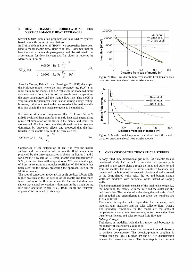
Comparison of the distribution of heat flux over the mantlesurface and the variation of the mantle fluid temperaturepredicted by the three apporaches is shown in figures 1 and 2for a mantle flow rate of 0.5 l/min, mantle inlet temperature of50°C, a uniform tank wall temperature of 20°C and annulus gapof 3 cm. A constant heat transfer coefficient of 200 W/m²K hasbeen used for the curves presenting the approach used in theMultiport model.The natural convection model (Shah et al) predicts substantiallyhigher heat flux in the top section of the mantle and thus muchfaster cooling of the flow in the mantle. As recent studies haveshown that natural convection is dominant in the mantle duringlow flow operation (Shah et al, 1998, 1999) the ”buoyantapproach” is continued in this study.
3 OVERVIEW OF THE THEORETICAL STUDIES
A body-fitted three-dimensional grid model of a mantle tank isdeveloped. Only half a tank is modelled as symmetry isassumed in the centre plane through the inlet and outlet to andfrom the mantle. The model is further simplified by modellingthe top and the bottom of the tank with horizontal walls insteadof the dome-shaped walls. Also, the top and bottom mantlewalls are modelled with horizontal walls instead of slopingwalls.The computational domain consists of the total heat storage, i.e.the inner tank, the mantle with the inlet and the outlet and thetank insulation. The number of nodes along the tank axis is I=42and in radial and circumferential directions the numbers areJ=25 and K=10.The model is supplied with input data for the water, tankmaterial, tank insulation and the solar collector fluid (water).The boundary conditions for the model are the ambienttemperature, mantle inlet temperature, outer convective heattransfer coefficients and solar collector fluid flow rate.Solving strategy:Turbulence is modelled with the k-ε model and buoyancy ismodelled with Boussinesq assumption.Under relaxation parameters are used on velocities and viscosityto achieve convergence. The velocity-pressure coupling istreated using the SIMPLE algorithm and QUICK discretisationis used for convection terms. The time step in the transient
1
10
100
1000
10000
100000
0 0.2 0.4 0.6 0.8Distance from top of mantle [m]
Hea
t fl
ux
[W/m
²]
Baur et alShah et alDrück et al
Figure 2: Heat flux distribution over mantle heat transfer areabased on one-dimensional heat transfer models.
20
30
40
50
0 0.2 0.4 0.6 0.8Distance from top of mantle [m]
Man
tle
flu
id t
emp
. [°C
]Baur et alShah et alDrück et al
Figure 3: Mantle fluid temperature variation down the mantlebased on one-dimensional heat transfer models.
simulations is 0.5 sec. The standard boundary conditions aregiven in Table 1.
Inner tank volume 170 litresTank material Steel: λ=60 W/mK, ρ=7820 kg/m³
cp=460 J/kg·KInsulation Mineral wool: λ=0.045 W/mK,
ρ=15 kg/m³, cp=800 J/kg·KCollector fluid WaterAmbient temperature 25°COuter thermalresistance
0.13 m²K/W
Table 1: Standard conditions and boundaries for the CFDsimulations.
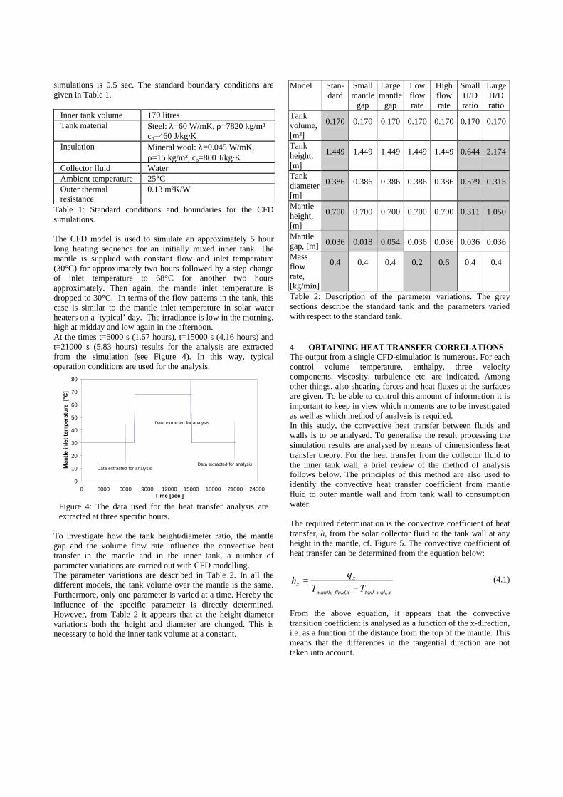
The CFD model is used to simulate an approximately 5 hourlong heating sequence for an initially mixed inner tank. Themantle is supplied with constant flow and inlet temperature(30°C) for approximately two hours followed by a step changeof inlet temperature to 68°C for another two hoursapproximately. Then again, the mantle inlet temperature isdropped to 30°C. In terms of the flow patterns in the tank, thiscase is similar to the mantle inlet temperature in solar waterheaters on a ‘typical’ day. The irradiance is low in the morning,high at midday and low again in the afternoon.At the times t=6000 s (1.67 hours), t=15000 s (4.16 hours) andt=21000 s (5.83 hours) results for the analysis are extractedfrom the simulation (see Figure 4). In this way, typicaloperation conditions are used for the analysis.
To investigate how the tank height/diameter ratio, the mantlegap and the volume flow rate influence the convective heattransfer in the mantle and in the inner tank, a number ofparameter variations are carried out with CFD modelling.The parameter variations are described in Table 2. In all thedifferent models, the tank volume over the mantle is the same.Furthermore, only one parameter is varied at a time. Hereby theinfluence of the specific parameter is directly determined.However, from Table 2 it appears that at the height-diametervariations both the height and diameter are changed. This isnecessary to hold the inner tank volume at a constant.
Model Stan-dard
Smallmantle
gap
Largemantle
gap
Lowflowrate
Highflowrate
SmallH/Dratio
LargeH/Dratio
Tankvolume,[m³]
0.170 0.170 0.170 0.170 0.170 0.170 0.170
Tankheight,[m]
1.449 1.449 1.449 1.449 1.449 0.644 2.174
Tankdiameter[m]
0.386 0.386 0.386 0.386 0.386 0.579 0.315
Mantleheight,[m]
0.700 0.700 0.700 0.700 0.700 0.311 1.050
Mantlegap, [m] 0.036 0.018 0.054 0.036 0.036 0.036 0.036
Massflowrate,[kg/min]
0.4 0.4 0.4 0.2 0.6 0.4 0.4
Table 2: Description of the parameter variations. The greysections describe the standard tank and the parameters variedwith respect to the standard tank.
4 OBTAINING HEAT TRANSFER CORRELATIONSThe output from a single CFD-simulation is numerous. For eachcontrol volume temperature, enthalpy, three velocitycomponents, viscosity, turbulence etc. are indicated. Amongother things, also shearing forces and heat fluxes at the surfacesare given. To be able to control this amount of information it isimportant to keep in view which moments are to be investigatedas well as which method of analysis is required.In this study, the convective heat transfer between fluids andwalls is to be analysed. To generalise the result processing thesimulation results are analysed by means of dimensionless heattransfer theory. For the heat transfer from the collector fluid tothe inner tank wall, a brief review of the method of analysisfollows below. The principles of this method are also used toidentify the convective heat transfer coefficient from mantlefluid to outer mantle wall and from tank wall to consumptionwater.
The required determination is the convective coefficient of heattransfer, h, from the solar collector fluid to the tank wall at anyheight in the mantle, cf. Figure 5. The convective coefficient ofheat transfer can be determined from the equation below:
x wall,tankxfluid, mantle
xx TT
qh
−= (4.1)
From the above equation, it appears that the convectivetransition coefficient is analysed as a function of the x-direction,i.e. as a function of the distance from the top of the mantle. Thismeans that the differences in the tangential direction are nottaken into account.
0
10
20
30
40
50
60
70
80
0 3000 6000 9000 12000 15000 18000 21000 24000Time [sec.]
Man
tle
inle
t te
mp
erat
ure
[°C
]
Data extracted for analysis
Data extracted for analysis
Data extracted for analysis
Figure 4: The data used for the heat transfer analysis areextracted at three specific hours.
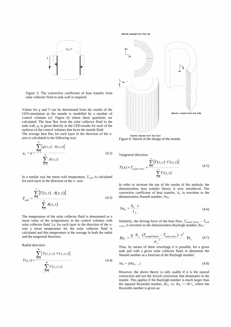
Values for q and T can be determined from the results of theCFD-simulation as the mantle is modelled by a number ofcontrol volumes (cf. Figure 6) where these quantities arecalculated. The heat flux from the solar collector fluid to thetank wall, q, is given directly in the CFD-results for each of thesurfaces of the control volumes that faces the mantle fluid.The average heat flux for each layer in the direction of the x-axis is calculated in the following way:
[ ]q q
q x z A x z
A x z
xz
n
z
n= =
⋅=
=
∑
∑
( , ) ( , )
( , )
1
1
(4.2)
In a similar way the mean wall temperature, Twall, is calculatedfor each layer in the direction of the x- axis:
[ ]
∑
∑
=
=
⋅=
n
z
n
z
zxA
zxAzxTT
1
1wall
),(
),(),((4.3)
The temperature of the solar collector fluid is determined as amean value of the temperatures in the control volumes withsolar collector fluid. I.e. for each layer in the direction of the x-axis a mean temperature for the solar collector fluid iscalculated and this temperature is the average in both the radialand the tangential direction:
Radial direction:
[ ]T x z
T x y z V x y z
V x y z
y
m
y
m( , )
( , , ) ( , , )
( , , )
=
⋅=
=
∑
∑1
1
(4.4)
Tangential direction:
[ ]
∑
∑
=
=
⋅==
n
z
n
zfluid mantle
zxV
zxVzxTTxT
1
1
),(
),(),()( (4.5)
In order to increase the use of the results of the analysis, thedimensionless heat transfer theory is now introduced. Theconvective coefficient of heat transfer, hx, is rewritten to thedimensionless Nusselt number, Nux:
Nuh x
xx
x=
⋅λ (4.6)
Similarly, the driving force of the heat flow, Tmantle fluid,x – Ttank
wall,x, is rewritten to the dimensionless Rayleigh number, Rax:
x
x
xx
xTTgRa Pr
)(2
3xtank wall,xfluid, mantle ⋅
⋅−⋅⋅=
ν
β(4.7)
Thus, by means of these rewritings it is possible, for a giventank and with a given solar collector fluid, to determine theNusselt number as a function of the Rayleigh number:
Nux = f(Rax, ...) (4.8)
However, the above theory is only usable if it is the naturalconvection and not the forced convection that dominates in themantle. This applies if the Rayleigh number is much larger thanthe squared Reynolds number, Rex, i.e. Rax >>Re²x, where theReynolds number is given as:
x
hx=?
Figure 5: The convective coefficient of heat transfer fromsolar collector fluid to tank wall is required.
Figure 6: Sketch of the design of the mantle.
x
xux ν
⋅=Re (4.9)
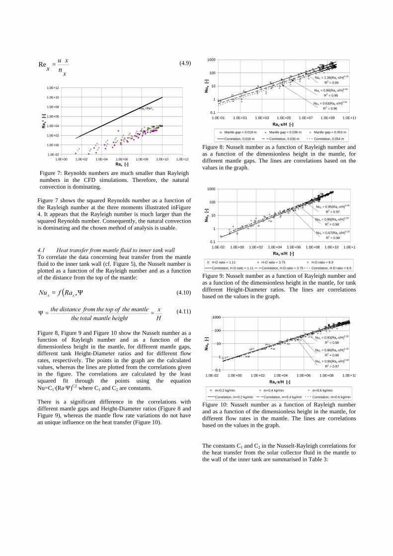
Figure 7 shows the squared Reynolds number as a function ofthe Rayleigh number at the three moments illustrated inFigure4. It appears that the Rayleigh number is much larger than thesquared Reynolds number. Consequently, the natural convectionis dominating and the chosen method of analysis is usable.
4.1 Heat transfer from mantle fluid to inner tank wallTo correlate the data concerning heat transfer from the mantlefluid to the inner tank wall (cf. Figure 5), the Nusselt number isplotted as a function of the Rayleigh number and as a functionof the distance from the top of the mantle:
( )Ψ= ,xx RafNu (4.10)
Hx
height mantle total themantle the of top the from distance the
==Ψ (4.11)
Figure 8, Figure 9 and Figure 10 show the Nusselt number as afunction of Rayleigh number and as a function of thedimensionless height in the mantle, for different mantle gaps,different tank Height-Diameter ratios and for different flowrates, respectively. The points in the graph are the calculatedvalues, whereas the lines are plotted from the correlations givenin the figure. The correlations are calculated by the leastsquared fit through the points using the equationNu=C1·(Ra·Ψ)C2 where C1 and C2 are constants.
There is a significant difference in the correlations withdifferent mantle gaps and Height-Diameter ratios (Figure 8 andFigure 9), whereas the mantle flow rate variations do not havean unique influence on the heat transfer (Figure 10).
Nux = 1.36(Rax·x/H)0.28
R2 = 0.99
Nux = 0.86(Rax·x/H)0.28
R2 = 0.98
Nux = 0.63(Rax·x/H)0.28
R2 = 0.960.1
1
10
100
1000
1.0E-01 1.0E+01 1.0E+03 1.0E+05 1.0E+07 1.0E+09 1.0E+11
Rax·x/H [-]
Nu
x [
-]
Mantle gap = 0.018 m Mantle gap = 0.036 m Mantle gap = 0.054 m
Correlation, 0.018 m Correlation, 0.036 m Correlation, 0.054 m
Figure 8: Nusselt number as a function of Rayleigh number andas a function of the dimensionless height in the mantle, fordifferent mantle gaps. The lines are correlations based on thevalues in the graph.
Nux = 0.67(Rax·x/H)0.28
R2 = 0.98
Nux = 0.86(Rax·x/H)0.28
R2 = 0.98
Nux = 0.95(Rax·x/H)0.28
R2 = 0.97
0.1
1
10
100
1000
1.0E-02 1.0E+00 1.0E+02 1.0E+04 1.0E+06 1.0E+08 1.0E+10 1.0E+12
Rax·x/H [-]
Nu
x [
-]
H-D ratio = 1.11 H-D ratio = 3.75 H-D ratio = 6.9
Correlation, H-D ratio = 1.11 Correlation, H-D ratio = 3.75 Correlation, H-D ratio = 6.9
Figure 9: Nusselt number as a function of Rayleigh number andas a function of the dimensionless height in the mantle, for tankdifferent Height-Diameter ratios. The lines are correlationsbased on the values in the graph.
Nux = 0.93(Rax·x/H)0.28
R2 = 0.98
Nux = 0.86(Rax·x/H)0.28
R2 = 0.98
Nux = 0.86(Rax·x/H)0.28
R2 = 0.970.1
1
10
100
1000
1.0E-02 1.0E+00 1.0E+02 1.0E+04 1.0E+06 1.0E+08 1.0E+10
Rax·x/H [-]
Nu
x [
-]
m=0.2 kg/min m=0,4 kg/min m=0.6 kg/min
Correlation, m=0.2 kg/min Correlation, m=0.4 kg/min Correlation, m=0.6 kg/min
Figure 10: Nusselt number as a function of Rayleigh numberand as a function of the dimensionless height in the mantle, fordifferent flow rates in the mantle. The lines are correlationsbased on the values in the graph.
The constants C1 and C2 in the Nusselt-Rayleigh correlations forthe heat transfer from the solar collector fluid in the mantle tothe wall of the inner tank are summarised in Table 3:
1.0E-02
1.0E+00
1.0E+02
1.0E+04
1.0E+06
1.0E+08
1.0E+10
1.0E+12
1.0E+00 1.0E+02 1.0E+04 1.0E+06 1.0E+08 1.0E+10 1.0E+12
Rax [-]
Re x
² [
-]
Rax=Re²x
Figure 7: Reynolds numbers are much smaller than Rayleighnumbers in the CFD simulations. Therefore, the naturalconvection is dominating.
Variation C1 C2
Mantle gap = 0.018 m 1.36 0.28
Mantle gap = 0.036 m 0.86 0.28
Mantle gap = 0.054 m 0.63 0.28
Height-Diameter ratio = 1.11 0.95 0.28
Height-Diameter ratio = 3.75 0.86 0.28
Height-Diameter ratio = 6.90 0.67 0.28
Mantle flow rate = 0.2 kg/min. 0.93 0.28
Mantle flow rate = 0.4 kg/min. 0.86 0.28
Mantle flow rate = 0.6 kg/min. 0.86 0.28
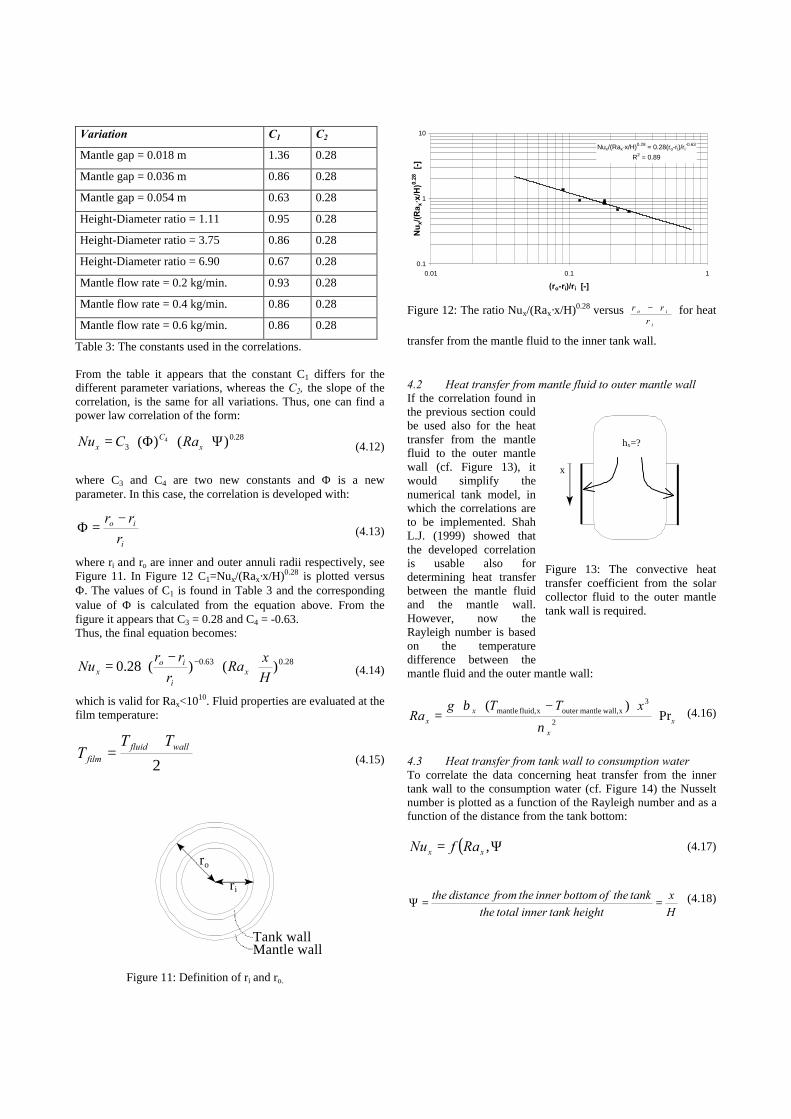
Table 3: The constants used in the correlations.
From the table it appears that the constant C1 differs for thedifferent parameter variations, whereas the C2, the slope of thecorrelation, is the same for all variations. Thus, one can find apower law correlation of the form:
28.03 )()( 4 Ψ⋅⋅Φ⋅= x
Cx RaCNu (4.12)
where C3 and C4 are two new constants and Φ is a newparameter. In this case, the correlation is developed with:
i
io
r
rr −=Φ (4.13)
where ri and ro are inner and outer annuli radii respectively, seeFigure 11. In Figure 12 C1=Nux/(Rax·x/H)0.28 is plotted versusΦ. The values of C1 is found in Table 3 and the correspondingvalue of Φ is calculated from the equation above. From thefigure it appears that C3 = 0.28 and C4 = -0.63.Thus, the final equation becomes:
28.063.0 )()(28.0Hx
Rar
rrNu x
i
iox ⋅⋅
−⋅= −
(4.14)
which is valid for Rax<1010. Fluid properties are evaluated at thefilm temperature:
2wallfluid
film
TTT
+= (4.15)
Nux/(Rax·x/H)0.28 = 0.28(ro-ri)/ri-0.63
R2 = 0.89
0.1
1
10
0.01 0.1 1
(ro-ri)/ri [-]
Nu
x/(R
a x·x
/H)0.
28 [
-]
Figure 12: The ratio Nux/(Rax·x/H)0.28 versus i
io
r
rr − for heat
transfer from the mantle fluid to the inner tank wall.
4.2 Heat transfer from mantle fluid to outer mantle wallIf the correlation found inthe previous section couldbe used also for the heattransfer from the mantlefluid to the outer mantlewall (cf. Figure 13), itwould simplify thenumerical tank model, inwhich the correlations areto be implemented. ShahL.J. (1999) showed thatthe developed correlationis usable also fordetermining heat transferbetween the mantle fluidand the mantle wall.However, now theRayleigh number is basedon the temperaturedifference between themantle fluid and the outer mantle wall:
x
x
xx
xTTgRa Pr
)(2
3x wall,mantleouter xfluid, mantle ⋅
⋅−⋅⋅=
ν
β(4.16)
4.3 Heat transfer from tank wall to consumption waterTo correlate the data concerning heat transfer from the innertank wall to the consumption water (cf. Figure 14) the Nusseltnumber is plotted as a function of the Rayleigh number and as afunction of the distance from the tank bottom:
( )Ψ= ,xx RafNu (4.17)
Hx
height tank inner total thetank the of bottom inner the from distance the
==Ψ (4.18)
ro
ri
Tank wallMantle wall
Figure 11: Definition of ri and ro.
x
hx=?
Figure 13: The convective heattransfer coefficient from the solarcollector fluid to the outer mantletank wall is required.
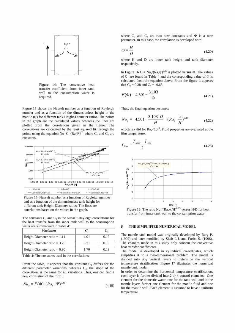
Figure 15 shows the Nusselt number as a function of Rayleighnumber and as a function of the dimensionless height in themantle (ψ) for different tank Height-Diameter ratios. The pointsin the graph are the calculated values, whereas the lines areplotted from the correlations given in the figure. Thecorrelations are calculated by the least squared fit through thepoints using the equation Nu=C1·(Ra·Ψ)C2 where C1 and C2 areconstants.
The constants C1 and C2 in the Nusselt-Rayleigh correlations forthe heat transfer from the inner tank wall to the consumptionwater are summarised in Table 4:
Variation C1 C2
Height-Diameter ratio = 1.11 4.01 0.19
Height-Diameter ratio = 3.75 3.71 0.19
Height-Diameter ratio = 6.90 1.70 0.19
Table 4: The constants used in the correlations.
From the table, it appears that the constant C1 differs for thedifferent parameter variations, whereas C2, the slope of thecorrelation, is the same for all variations. Thus, one can find anew correlation of the form:
19.0)()( Ψ⋅⋅Φ= xx RaFNu (4.19)
where C3 and C4 are two new constants and Φ is a newparameter. In this case, the correlation is developed with:
DH
=Φ (4.20)
where H and D are inner tank height and tank diameterrespectively.
In Figure 16 C1= Nux/(Raxψ)0.19 is plotted versus Φ. The valuesof C1 are found in Table 4 and the corresponding value of Φ iscalculated from the equation above. From the figure it appearsthat C3 = 0.28 and C4 = -0.63.
Φ−=Φ
103.3501.4)(F (4.21)
Thus, the final equation becomes:
19.0)(103.3
501.4Hx
RaH
DNu xx ⋅⋅
⋅
−= (4.22)
which is valid for Rax<1011. Fluid properties are evaluated at thefilm temperature:
2wallfluid
film
TTT
+= (4.23)
5 THE SIMPLIFIED NUMERICAL MODEL
The mantle tank model was originally developed by Berg P.(1992) and later modified by Shah L.J. and Furbo S. (1996).The changes made in this study only concern the convectiveheat transfer coefficients.The model is developed in cylindrical co-ordinates, whichsimplifies it to a two-dimensional problem. The model isdivided into NZ3 vertical layers to determine the verticaltemperature stratification. Figure 17 illustrates the numericalmantle tank model.In order to determine the horizontal temperature stratification,each layer is further divided into 2 or 4 control elements: Oneelement for the domestic water, one for the tank wall and in themantle layers further one element for the mantle fluid and onefor the mantle wall. Each element is assumed to have a uniformtemperature.
x hx=?
Figure 14: The convective heattransfer coefficient from inner tankwall to the consumption water isrequired.
Nux = 4.01(Rax·x/H)0.19
R2 = 0.84
Nux = 3.71(Rax·x/H)0.19
R2 = 0.91
Nux = 1.70(Rax·x/H)0.19
R2 = 0.94
0.10
1.00
10.00
100.00
1000.00
1.0E-04 1.0E-02 1.0E+00 1.0E+02 1.0E+04 1.0E+06 1.0E+08 1.0E+10 1.0E+12Rax·x/H [-]
Nu
x [
-]
H/D=1.11 H/D=3.67 H/D=6.90
Correlation, H/D=1.11 Correlation, H/D=3.67 Correlation, H/D=6.9
Figure 15: Nusselt number as a function of Rayleigh numberand as a function of the dimensionless tank height fordifferent tank Height-Diameter ratios. The lines arecorrelations based on the values in the graph.
0
1
2
3
4
5
6
0 1 2 3 4 5 6 7 8
H/D [-]
Nu
x/(R
a x·x
/H)0.
19 [
-]
Nux/(Rax·x/H)0.19=4.501-3.103/(H/D)
R2 = 0.99
Figure 16: The ratio Nux/(Rax·x/H)0.19 versus H/D for heattransfer from inner tank wall to the consumption water.
The energy balance in each layer, i, can be presented as:
tapauxlosscondmixsoli QQQQQQQ +++++=∆ (5.1)
Qmix, means energy transport caused by mixing when a lowerlayer has a higher temperature than a higher layer. Thetemperature gradient along the vertical direction is calculated bymodelling the inner tank with NZ3 elements. The inner tankcontains consumption water and the energy balances musttherefore include eventual draw-off.The correlations derived above enter the energy balance as apart of Qloss as energy transfer through the walls is treated aslosses (positive or negative) for each control element.
6 COMPARISON WITH AN OUTDOOR MEASUREDSYSTEM
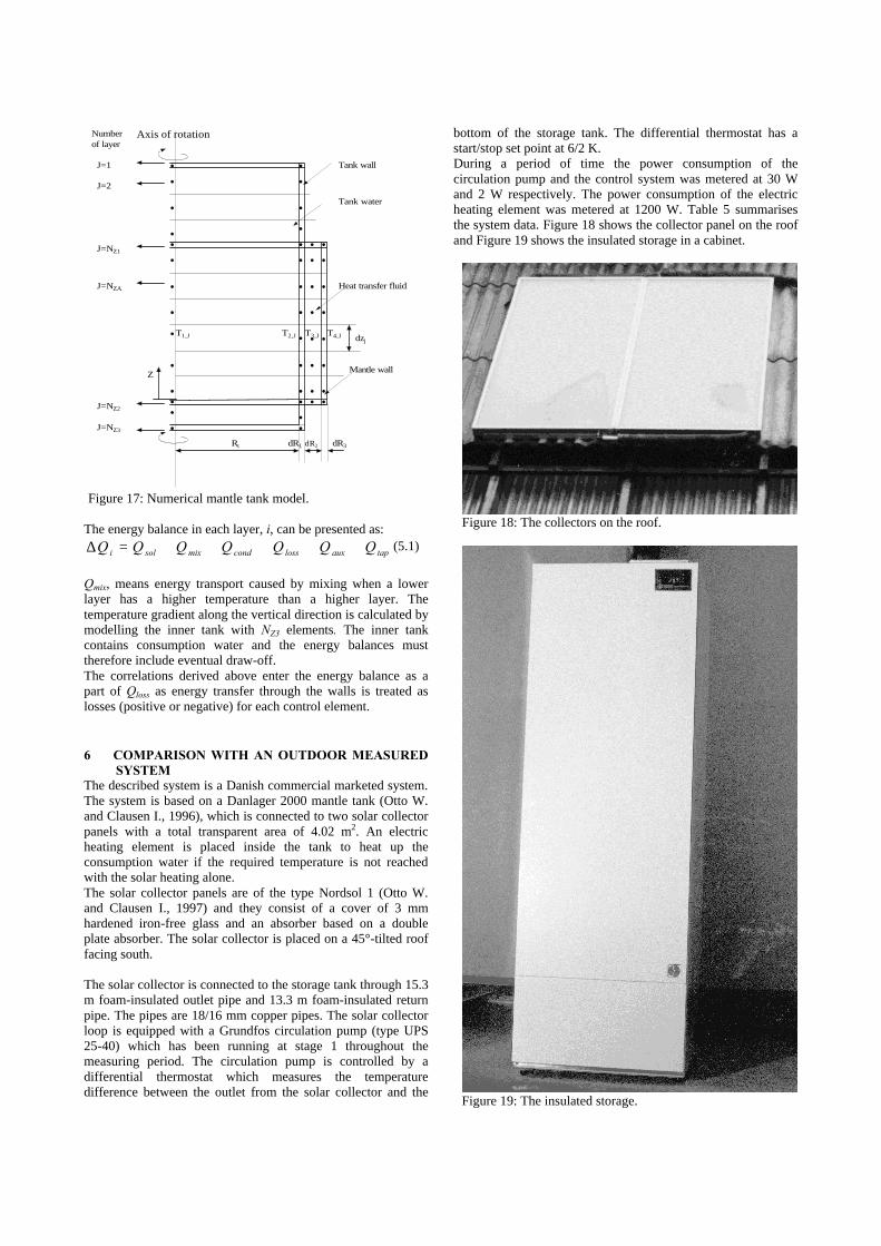
The described system is a Danish commercial marketed system.The system is based on a Danlager 2000 mantle tank (Otto W.and Clausen I., 1996), which is connected to two solar collectorpanels with a total transparent area of 4.02 m2. An electricheating element is placed inside the tank to heat up theconsumption water if the required temperature is not reachedwith the solar heating alone.The solar collector panels are of the type Nordsol 1 (Otto W.and Clausen I., 1997) and they consist of a cover of 3 mmhardened iron-free glass and an absorber based on a doubleplate absorber. The solar collector is placed on a 45°-tilted rooffacing south.
The solar collector is connected to the storage tank through 15.3m foam-insulated outlet pipe and 13.3 m foam-insulated returnpipe. The pipes are 18/16 mm copper pipes. The solar collectorloop is equipped with a Grundfos circulation pump (type UPS25-40) which has been running at stage 1 throughout themeasuring period. The circulation pump is controlled by adifferential thermostat which measures the temperaturedifference between the outlet from the solar collector and the
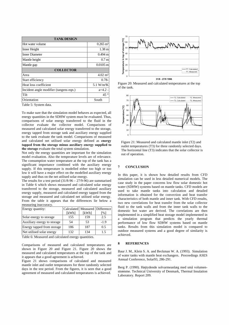
bottom of the storage tank. The differential thermostat has astart/stop set point at 6/2 K.During a period of time the power consumption of thecirculation pump and the control system was metered at 30 Wand 2 W respectively. The power consumption of the electricheating element was metered at 1200 W. Table 5 summarisesthe system data. Figure 18 shows the collector panel on the roofand Figure 19 shows the insulated storage in a cabinet.
l l
l l
l l
ll
l l l l
l l l l
l ll l
llll
l
l
l
lll
l
lll
l
l
lll
l l
l
l
l
Axis of rotation
Tank wall
Mantle wall
J=1
J=2
J=NZ1
J=NZ2
J=NZ3
Numberof layer
T1,J T2,J T3,J T4,J dzj
Heat transfer fluid
Tank water
R dR1 dR2 dR3
J=NZA
Z
t
Figure 17: Numerical mantle tank model.
Figure 18: The collectors on the roof.
Figure 19: The insulated storage.
TANK DESIGN
Hot water volume 0.265 m³
Inner Height 1.38 m
Inner Diameter 0.494 m
Mantle height 0.7 m
Mantle gap 0.0105 m
COLLECTORArea 4.02 m²
Start efficiency 0.78-
Heat loss coefficient 5.1 W/m²K
Incident angle modifier (tangens eqn.) a=4.2 -
Tilt 45 °
Orientation South
Table 5: System data.
To make sure that the simulation model behaves as expected, allenergy quantities in the SDHW system must be evaluated. Thus,comparisons of solar energy transferred to the fluid in thecollector evaluate the collector model. Comparisons ofmeasured and calculated solar energy transferred to the storage,energy tapped from storage tank and auxiliary energy suppliedto the tank evaluate the tank model. Comparisons of measuredand calculated net utilised solar energy defined as energytapped from the storage minus auxiliary energy supplied tothe storage evaluate the total system simulation.Not only the energy quantities are important for the simulationmodel evaluation. Also the temperature levels are of relevance.The consumption water temperature at the top of the tank has asignificant importance combined with the auxiliary energysupply. If this temperature is modelled either too high or toolow it will have a major effect on the modelled auxiliary energysupply and thus on the net utilised solar energy.The results for a test period (31/8-96 – 27/9-96) are summarisedin Table 6 which shows measured and calculated solar energytransferred to the storage, measured and calculated auxiliaryenergy supply, measured and calculated energy tapped from thestorage and measured and calculated net utilised solar energy.From the table it appears that the differences lie below ameasuring inaccuracy.Energy quantity: Calculated
[kWh]Measured
[kWh]Difference
[%]Solar energy to storage 155 159 2.5
Auxiliary energy to storage 54 53 -1.9
Energy tapped from storage 186 187 0.5
Net utilised solar energy 132 134 1.5
Table 6: Measured and calculated energy quantities.
Comparisons of measured and calculated temperatures areshown in Figure 20 and Figure 21. Figure 20 shows themeasured and calculated temperatures at the top of the tank andit appears that a good agreement is achieved.Figure 21 shows comparisons of calculated and measuredmantle inlet and outlet temperatures for three randomly selecteddays in the test period. From the figures, it is seen that a goodagreement of measured and calculated temperatures is achieved.
7 CONCLUSION
In this paper, it is shown how detailed results from CFDsimulation can be used in less detailed numerical models. Thecase study in the paper concerns low flow solar domestic hotwater (SDHW) systems based on mantle tanks. CFD models areused to take mantle tanks into calculation and detailedinformation is obtained for the convection and heat transfercharacteristics of both mantle and inner tank. With CFD results,two new correlations for heat transfer from the solar collectorfluid to the tank walls and from the inner tank walls to thedomestic hot water are derived. The correlations are thenimplemented in a simplified heat storage model implemented ina simulation program that predicts the yearly thermalperformance of low flow SDHW systems based on mantletanks. Results from this simulation model is compared tooutdoor measured systems and a good degree of similarity isachieved.
8 REFERENCES
Baur J. M., Klein S. A. and Beckman W. A. (1993). Simulationof water tanks with mantle heat exchangers. Proceedings ASESAnnual Conference, Solar93, 286-291.
Berg P. (1990). Højtydende solvarmeanlæg med små volumen-strømme. Technical University of Denmark, Thermal InsulationLaboratory. Report 209.
0
10
20
30
40
50
60
70
31/8 - 27/9 1996
Tem
per
atu
re in
to
p o
f st
ora
ge
[°C
]
T7, Calculated
T7, Measured
Figure 20: Measured and calculated temperatures at the topof the tank.
0
10
20
30
40
50
60
70
80
Tem
per
atu
re [
°C]
T2, Calculated T2, Measured
T3, Calculated T3, Measured
Figure 21: Measured and calculated mantle inlet (T2) andoutlet temperatures (T3) for three randomly selected days.The horizontal line (T3) indicates that the solar collector isout of operation.
Drück H. and Pausinger T. (1997). MULTIPORT Store –Model for TrnSys. Type 140. Universität Stuttgart. Institut fürThermodynamik und Wärmetechnik.
Klein S.A et al. (1996). TRNSYS 14.1, User Manual.University of Wisconsin Solar Energy Laboratory.
Mercer W. E., Pearce W. M. and Hitchcock J. E (1967) Laminarforced convection in the entrance region between parallel flatplates. ASME J of Heat Transfer V89, 251-257.
Furbo, S. (1993). Optimum Design of Small DHW Low FlowSolar Heating Systems. Proceedings, ISES Solar WorldCongress 1993, Budapest, Hungary.
Furbo S. and Shah L.J. (1997). Laboratory Tests of SmallSDHW Systems. Proceedings NorthSun’97, Volume I pp. 153-159. Espoo, Finland 1997. ISBN 951-22-3567-6.
Furbo S. (1998) Ydelser af solvarmeanlæg under laboratorie-mæssige forhold. Note U-18.Technical University of Denmark,Department of Buildings and Energy.
Otto W. and Clausen, I. (1996). Beholderprøvning. Nilan A/S.Danlager 2000. Prøvningsrapport D3070. Prøvestationen forSolenergi.
Olesen M. and Clausen, I. (1997). Måling af solfanger-effektivitet. Nordsol A/S. Nordsol1. Prøvningsrapport D2115 B.Prøvestationen for Solenergi.
Shah L.J. and Furbo S. (1996). Optimisation of Mantle Tanksfor Low Flow Solar Heating Systems. Proceedings EuroSun’96, Vol.I, pp. 369-375. Freiburg. September 1996.
Shah L. J. and Furbo S. (1998). Correlation of experimentaland theoretical data for mantle tanks used in low flow SDHWsystems. Solar Energy V64, 245-256.
Shah L.J., Morrison G.L. and Behnia M. (1998). ModellingMantle Tanks for SDHW Systems using PIV and CFD.Proceedings, Vol. 2, pp. III.3.1-6. EuroSun 98, Portorôz,Slovenia.
Shah L.J. (1999). Investigation and modelling of low flowSDHW systems. Report R-034. Department of Buildings andEnergy, Technical University of Denmark. ISBN 87-7877-035-1.
Shah L.J., Morrison G.L. and Behnia M. (1999).Characteristics of vertical mantle heat exchangers for solarwater heaters. Solar99 ISES Israel 1999.
9 NOMENCLATURE
A(x,z) area of each control volume of the current layer in the
x-direction [m²]
g acceleration due to gravity [m/s²]
h convective heat transfer coefficient [W/m²K]
m number of control volumes in the radial direction [-]
n number of control volumes in the tangential direction [-]
q heat flux [W/m²]
qx is the average heat flow at a specific level in the x-
direction [W/m²]
q(x,z) heat flux at the surfaces of each control volume at a
specific level in the x-direction [W/m²]
∆Qi energy stored in the layer i [J]
Qmix convective energy due to mixing, entering layer no. i [J]
Qcond diffusive energy, entering layer no. i [J]
Qsol solar energy, entering layer no. i [J]
Qloss is the heat loss from the layer no. i [J]
Qaux is the auxiliary energy supplied to the layer no. i [J]
Qtap is the energy amount tapped from the layer no. i [J]
T temperature [K]T(x,z) mean temperature at a single tangential position in the
current level in the x-direction [K]
V(x,z) sum of the volume of the control volumes at the single
tangential positions in the current layer in the x-
direction [m³]
V(x,y,z) volume of the control volumes at the single tangential
and radial positions in the current layer in the x-
direction [m³]
Pr Prandtl number of the solar collector fluid [-]
u vertical velocity of the solar collector fluid [m/s]
β thermal volume expansion coefficient of the mantle
fluid [1/K]
λ thermal conductivity for the solar collector fluid [W/mK]
ν viscosity of the solar collector fluid [m²/s]