Embed Size (px)
Citation preview

NOVA SCOTIA POWER INC. UTILITY SERVICE REQUIREMENTS
FEBRUARY, 2009

NOVA SCOTIA POWER INC. UTILITY SERVICE REQUIREMENTS
Page 1
Table of ContentsPage
0 SCOPE................................................................................................................. 3
1 DEFINITIONS....................................................................................................... 3
2 DEVIATIONS FROM REQUIREMENTS............................................................... 5
3 THE CANADIAN ELECTRICAL CODE................................................................. 5
4 INTERFERENCE WITH UTILITY EQUIPMENT ................................................... 5
5 REQUIREMENTS FOR SERVICE CONNECTION .............................................. 5
5.1 Easements and Right of Way Requirements:............................................. 6
6 SUPPLY VOLTAGES ........................................................................................... 6
6.1 Secondary Supply Voltages ....................................................................... 7
7 LARGE ELECTRIC LOADS.................................................................................. 7
8 ELECTRIC MOTORS ........................................................................................... 8
9 TRANSFER EQUIPMENT FOR STANDBY POWER SYSTEMS ......................... 8
10 SERVICE CAPACITY........................................................................................... 9
10.1 Single Phase ........................................................................................... 9
10.2 Three Phase............................................................................................ 9
11 SERVICE TO RESIDENTIAL BUILDINGS (SINGLE OR MULTIPLE
OCCUPANCY) ................................................................................................... 10
12 SERVICE ENTRANCES..................................................................................... 10
12.2 Service Entrance Disconnect ................................................................ 11
12.3 Temporary Service Entrances ............................................................... 11
13 SERVICES REQUIRING PRIMARY EQUIPMENT............................................. 14
13.1 Policy..................................................................................................... 14
13.2 Customer Responsibilities ..................................................................... 14
13.3 NSPI Responsibilities ............................................................................ 16
13.4 Duct Banks ................................................................................................. 16
13.5 Customer Owned Secondary Cable ...................................................... 18
13.6 Ground Tie ............................................................................................ 19
13.7 Concrete Transformer Base .................................................................. 19
NOVA SCOTIA POWER INC. UTILITY SERVICE REQUIREMENTS
Page 2
13.8 Fibreglass or Composite Transformer Base .......................................... 20
13.9 Fire-Resisting Barriers........................................................................... 20
13.10 Mechanical Protection ........................................................................... 21
13.11 Definition of Backfill Materials ............................................................... 22
13.12 Primary Line Extensions........................................................................ 22
14 METERING......................................................................................................... 23
14.1 Electrical Contractor’s Responsibilities.................................................. 23
14.2 Meter Locations..................................................................................... 23
14.3 Instrument Transformers – 0 to 600 volts .............................................. 24
14.4 Secondary Wiring .................................................................................. 25
14.5 Service (System) Neutral....................................................................... 25
14.6 Three Phase Self-contained Metering Above 300V............................... 26
14.7 Primary Metering ................................................................................... 27
15 SERVICE REQUEST PROCESS ....................................................................... 28
Appendices
APPENDIX A SAFE CLEARANCES REPORT
APPENDIX B SERVICE ENTRANCE AND METERING CONFIGURATIONS
APPENDIX C NSPI STANDARD DRAWINGS
APPENDIX D NSPI APPROVED CONNECTORS LISTING
APPENDIX E NSPI APPROVED UNDERGROUND MATERIALS
NOVA SCOTIA POWER INC. UTILITY SERVICE REQUIREMENTS
Page 3
0 SCOPE
This document sets forth the minimum utility requirements for electrical service in the province of Nova Scotia, for all areas served by Nova Scotia Power Incorporated (NSPI). It is not to be regarded as a design specification and is not all inclusive with respect to the installation of electrical equipment or wiring.
These utility service requirements are in addition to the Canadian Electrical Code, Part 1 (CEC), the NSPI Electrical Inspection Authority, and NSPI Utility Standards.
Construction shall not be undertaken based solely on this document, contact with both the Supply and Inspection Authorities is required for confirmation of site specific requirements and/or conditions.
1 DEFINITIONS
Complex Structure: A complex structure is any structure that would be difficult to supply with a single
utility service due to its physical characteristics or electrical requirements. The designation of a structure as ‘complex’ must be mutually agreed upon by both the Supply and Inspection Authorities.
Customer: A Customer is defined as a person or company who is receiving, intends to receive,
or has received electrical energy or electrical services from NSPI. Requests for service may be made by someone acting legally on behalf of the person or company.
Consumer’s Service Conductors: This term refers to Consumer owned conductors. On an overhead entrance these would typically be the conductors in the service conduit from the point at which the Supply Authority makes connection at the service head to the Customer’s first service enclosure. On an underground entrance these would be the underground cables from the utility secondary system, or transformer to the Customer’s first service enclosure.
Firewall/Fire separation: Where occupancies of a building are separated by a firewall or a fire separation, the
occupancies may be considered as separate buildings for the purpose of electrical service. Firewalls and fire separations must be constructed in compliance with the National Building Code and confirmed as such in writing by a recognized building inspector, architect, or professional engineer.
NOVA SCOTIA POWER INC. UTILITY SERVICE REQUIREMENTS
Page 4
Inspection Authority: The Nova Scotia Department of Labour and Workforce Development has
responsibility for enforcement of the Electrical Requirements in the Province of Nova Scotia. Nova Scotia Power’s Electrical Inspection Department is authorized by their office to enforce the Canadian Electrical Code, Part 1 within NSPI’s Service Area. The NSPI Electrical Inspection Department will also enforce the Utility Standards where applicable.
Inspection Department: Within this document refers to the Nova Scotia Power Electrical Inspection
Department.
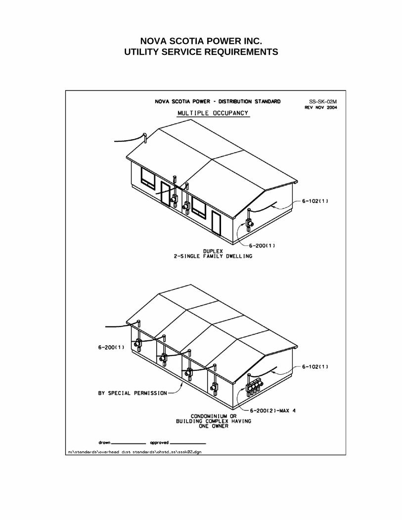
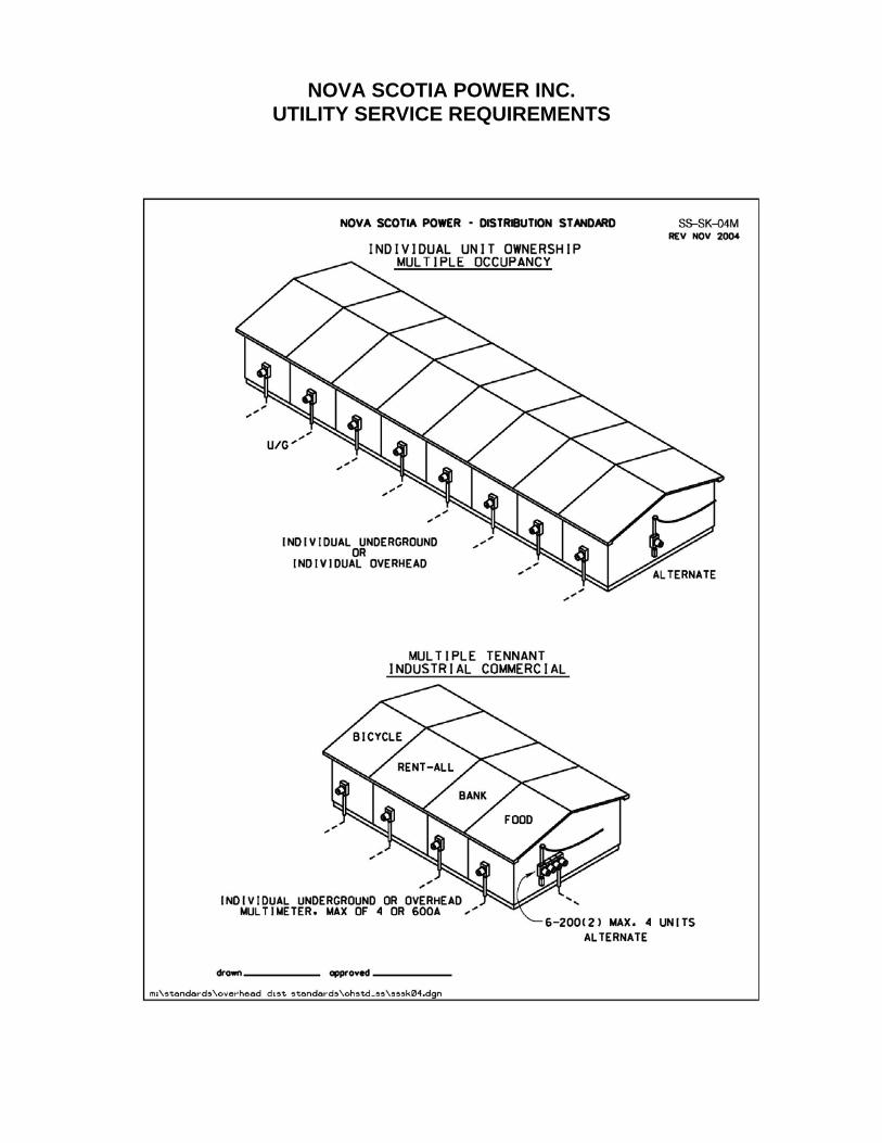
Multiple Occupancy Buildings: This includes strip malls or plazas, duplex, row and semi-detached housing, and
other such structures.
Primary: As used in this document in relation to voltages, primary means voltages in excess
of 750 volts.
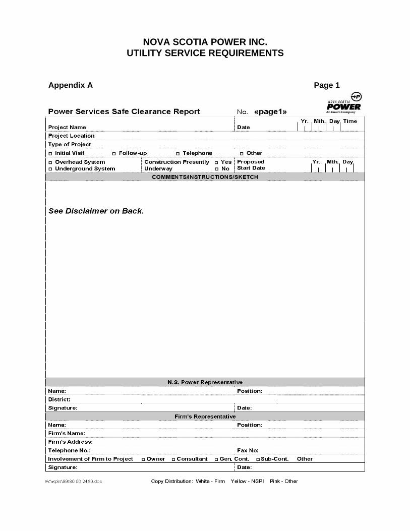
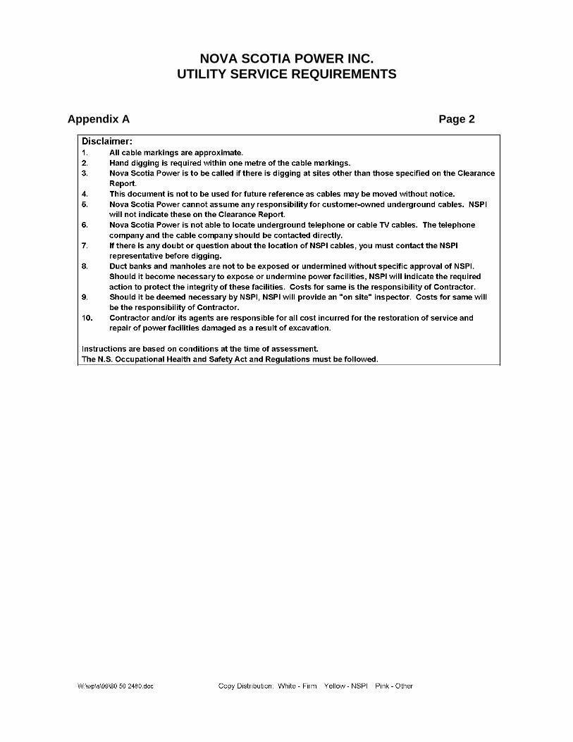
Safe Clearances Report: A power services safe clearance report is a detailed report identifying any potential
safety issues/hazards to the requested party who is required to complete work in close proximity of NSPI plant (lines or equipment). A copy of this report is provided to the requestor.
Service Box: An approved assembly consisting of a metal box or cabinet constructed so that it
may be locked or sealed, containing either service fuses and a service switch or a circuit breaker, and of such design that either the switch or circuit breaker may be manually operated when the box is closed.
Supply Authority (Interchangeable with Utility): Nova Scotia Power, having the authority to supply electrical energy within its service
area.
Utility Approval: Written or verbal approval from the Utility.
Utility Supply Conductors: This term refers to the utility owned conductors connecting the Consumer’s Service
Conductors to the utility’s system or transformer.
NOVA SCOTIA POWER INC. UTILITY SERVICE REQUIREMENTS
Page 5
2 DEVIATIONS FROM REQUIREMENTS
Utility and/or Inspection Department Approval is necessary for deviations from these requirements.
3 THE CANADIAN ELECTRICAL CODE
These Utility Service Requirements contain references to the Canadian Electrical Code, Part 1. This document does not however, constitute a complete explanation of all CEC rules, which apply to service entrances.
Where the Canadian Electrical Code refers to compliance with the requirements of the local Supply Authority, then NSPI shall be consulted for approval.
4 INTERFERENCE WITH UTILITY EQUIPMENT
The Supply Authority does not permit unauthorized disconnection or removal of meters, meter seals, utility supply conductors or any of its equipment. Requests for disconnection or removal of utility equipment shall be made to the NSPI’s call center at (800)-428-6230.
Unauthorized removal of NSPI revenue meters may result in charges for retesting of the meter.
5 REQUIREMENTS FOR SERVICE CONNECTION
Service entrances will be connected upon compliance with the following requirements:
a) Supply Authority approval of the service entrance location, capacity and provisions for metering equipment.
b) A valid wiring permit, for the installation, issued by NSPI.
c) Authorization for a utility connection from the Inspection Department.
d) For all consumer service entrances, or sub-services, larger than 250 Amps or 250 volts, the customer or their agent shall submit plans and specifications to the utility. Submittal of electrical plans shall comply with NSPI Electrical Inspection Bulletin B-2-014 “Submittal of Electrical Plans for Inspection Department Acceptance”.
e) Compliance of the installation with all other requirements of this document and the Canadian Electrical Code, Part 1.
NOVA SCOTIA POWER INC. UTILITY SERVICE REQUIREMENTS
Page 6
f) Establishment of all easement and right-of-way requirements as specified in Section 5.1.
g) A valid building permit when the municipal government with jurisdiction requires one for the facility being built by the customer.
5.1 Easements and Right of Way Requirements:
The customer has overall responsibility for obtaining any easements or licenses. Where a service route as approved by the Supply Authority crosses private property the Customer shall be responsible for supplying and clearing the route.
The Customer is responsible for any costs incurred by NSPI in acquiring easements or licenses where regulations do not allow the customer to obtain them on behalf of NSPI.
The actual right-of-way dimensions and orientation details may vary by location. The Supply Authority will provide and confirm the requirements on a case by case basis.
5.2 Changes in Service Requirements Before Connection
Should the customer change the service voltage and/or the capacity requirements or any other electrical parameters of the new service after NSPI has installed the facilities to meet the original requirements, then the customer must pay all additional costs associated with reworking the new NSPI plant.
The customer is also responsible for all costs associated with physical changes that arise after utility facilities and equipment are installed according to the original site layout.
6 SUPPLY VOLTAGES
NSPI will normally supply one service with standard voltages and characteristics as specified in this section.
When multiple supplies of different voltages or characteristics are requested for a single building (complex structure), approval must be obtained from the Supply Authority by the Customer or their Agent. Approval from the Inspection Authority for designation as this type of structure should also be obtained.
The Customer shall supply all transformation necessary to serve loads utilizing voltages different from that which is normally supplied by NSPI.
NOVA SCOTIA POWER INC. UTILITY SERVICE REQUIREMENTS
Page 7
The frequency of all supply voltages is 60 hertz.
Refer to Section 13 for requirements associated with service at primary voltages, which includes padmount transformer installations. Contact must be made with the Supply Authority for confirmation of the requirements for each particular installation.
6.1 Secondary Supply Voltages
The following are standard secondary and service voltages:
a) 120/240 volt, single phase, three wire; or
b) 120/208 volt, three phase, four wire grounded wye; or
c) 347/600 volt, three phase, four wire grounded wye.
Where a high resistance grounded installation is requested, the configuration must be approved by the Supply Authority, and must conform to the Canadian Electrical Code.
Electric service may be provided to customers at other voltages with special permission from the supply authority.
Existing non-standard installations shall be changed to conform with these requirements when alterations are made to the service. Consultation with the Engineering Department for the area in which the service resides is necessary.
7 LARGE ELECTRIC LOADS
Operating large loads such as motors, electric furnaces, electric welders, air conditioners, heat pumps, etc., can produce momentary voltage sag or ‘flicker’: It is the responsibility of the Customer to ensure that electric loads which can produce momentary voltage sags or flicker are configured or controlled in such a way that sag or flicker is minimized.
The operating requirements of large loads should be given consideration during design of the service entrance. Consultation with the Supply Authority is required to ensure the adequacy of the Utility supply equipment. Failure to do so will result in charges to the customer for costs associated with any reworking of newly installed NSPI equipment that is required.
NOVA SCOTIA POWER INC. UTILITY SERVICE REQUIREMENTS
Page 8
8 ELECTRIC MOTORS
8.1 Motor Sizes:
a) The maximum motor sizes permitted for starting across the line shall be:i) Single phase, 5.6 kW (7.5 horsepower);ii) Three phase 120/208 V, 11.2 kW (15 horsepower); iii) Three phase 347/600 V, 30 kW (40 horsepower).
b) Larger motors are permitted where: i) The Customer installs reduced voltage or variable frequency
start; or ii) Upon examination of the utility’s system capabilities and the
motor’s characteristics, Utility Approval for starting across the line is granted.
8.2 Motor Protection:
The Customer shall be responsible to provide all motor protection as per the CEC.
NOTE: Normal overload protection will likely not provide adequate protection during loss of one supply phase. Loss of one phase of the utility supply (or of the building distribution system) may cause overheating and damage to three phase motors. Therefore, protection against the loss of one supply phase is recommended and shall be the responsibility of the customer.
9 TRANSFER EQUIPMENT FOR STANDBY POWER SYSTEMS
Transfer switches for transferring the source of power from the utility system to a standby power system must meet the requirements of CEC 14-612. The switch shall not allow the two sources to operate in parallel to prevent energizing or back feeding a de-energized utility distribution line on which crews may be working.
Other devices such as purpose built meter base accessories that accommodate the connection of standby generators are also acceptable and must have the approval of the Inspection Authority.
NOVA SCOTIA POWER INC. UTILITY SERVICE REQUIREMENTS
Page 9
10 SERVICE CAPACITY
10.1 Single Phase
a) The maximum single-phase overhead service entrance capacity shall be 600 amps.
b) The maximum single-phase service entrance capacity run underground terminating at a utility pole shall be 400 amps.
c) Notwithstanding paragraphs (a) and (b), an 800 amp single phase underground service may be permitted with Utility Approval. Installation shall be in accordance with Section 13.
10.2 Three Phase
a) The maximum overhead three phase, 120/208 volt service entrance capacity shall be 600 amps.
b) The maximum overhead three phase, 347/600 volt service entrance capacity shall be 200 amps.
c) The maximum three-phase, 120/208 volt service entrance capacity run underground terminating at a utility pole shall be 600 amps.
d) The maximum three-phase, 347/600 volt service entrance capacity run underground terminating at a utility pole shall be 400 amps.
e) Notwithstanding paragraphs (a) and (b) above, larger overhead service ampacities may be permitted with Supply Authority approval. These are generally industrial or commercial buildings that are supplied from platform mounted utility transformers that are connected to the building by short conductors of large trade size. This type of installation is not preferred.
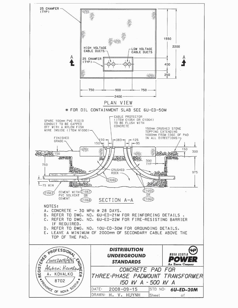
f) Services on which the required transformer capacity exceeds 225 kVA, three phase, regardless of service voltage, will normally be supplied from a padmount transformer. Installation details for padmounted transformers are in Section 13. Other transformer arrangements/designs are possible, consult with the supply authority.
NOVA SCOTIA POWER INC. UTILITY SERVICE REQUIREMENTS
Page 10
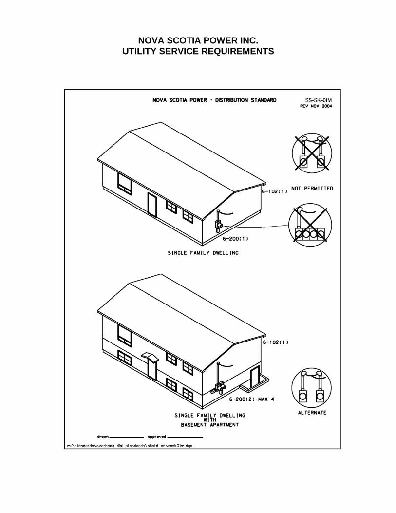
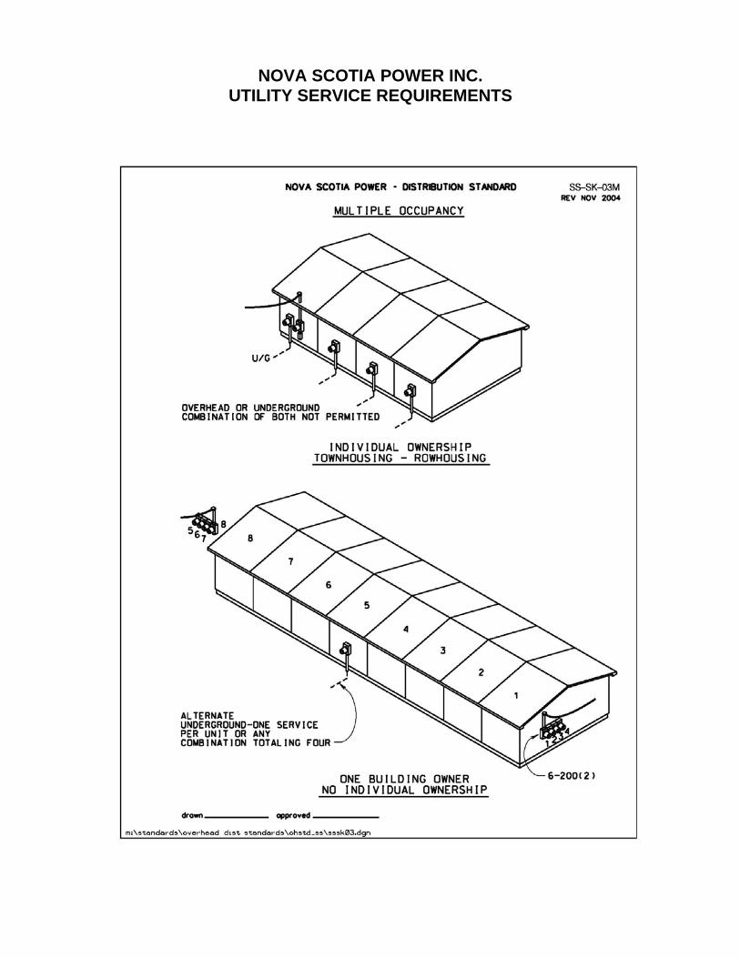
11 SERVICE TO RESIDENTIAL BUILDINGS (SINGLE OR MULTIPLE OCCUPANCY)
a) Normally, one set of utility supply conductors is run to a residential multi-occupancy building.
b) Where more than one set of utility supply conductors is run to a residential multiple occupancy building:
i) The occupancies shall be completely self-contained (i.e. no indoor access between occupancies); and
ii) The occupancies shall not be located one above the other; and iii) The occupancies shall have a separate entrance with direct access to
ground level.
c) Fire pumps or other emergency systems can be supplied from a second utility supply.
d) Complex structures may have more than one utility supply. Both the Supply and Inspection Authorities must approve all installations where more than one supply service is requested or required.
e) See Section 12 and Appendix B for service entrance guidelines.
12 SERVICE ENTRANCES
12.1 General
Before commencing any service entrance installation (new, relocation, or upgrade of service) the Customer or their agent shall contact NSPI to obtain approval for the route of the utility supply conductors. The location of the service head and the location of the point of attachment for the utility supply conductors shall be in accordance with both the Canadian Electrical Code and NSPI standards.
The responsibility for obtaining easements (in a form specified by NSPI) and developing the right of way (ROW) are the responsibility of the customer as specified previously in Section 5.1.
NOVA SCOTIA POWER INC. UTILITY SERVICE REQUIREMENTS
Page 11
12.2 Service Entrance Disconnect
a) As per CEC Rule 6-206, subrule (1), paragraph (e), the main service disconnect shall be located as close as practicable to the point where the customer’s service conductors enter the building. ‘As close as practicable’ shall not be more than 3 m in length and applies to the section of raceway which enters the building before it enters the main service switch.
b) When applied to a mobile home, in particular a skirted mobile home, as close as practicable shall not be more than 7.5 m. When mobile homes are set on a permanent foundation, as close as practicable shall be as per paragraph a) above.
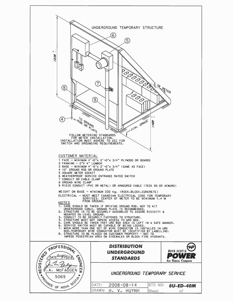
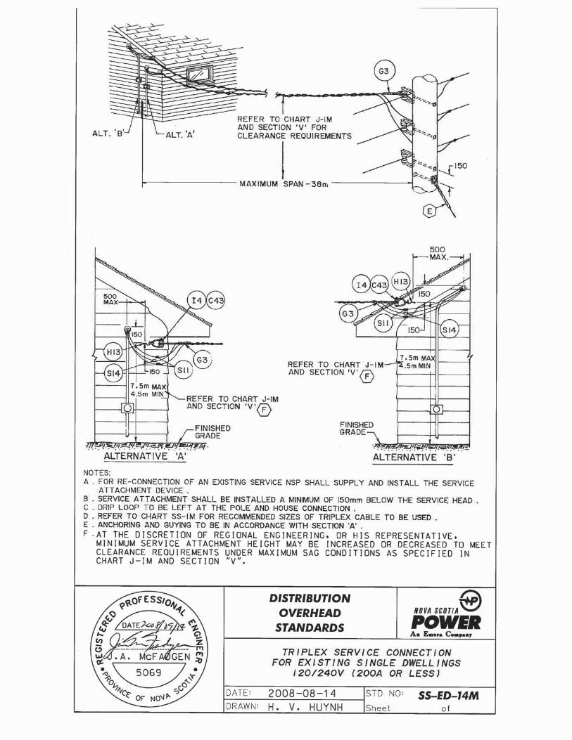
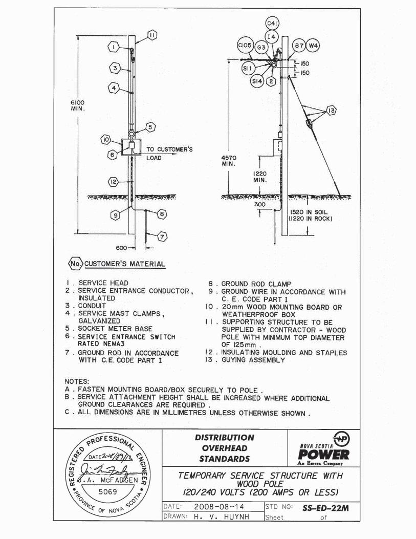
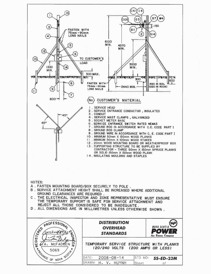
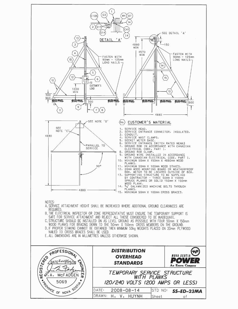
12.3 Temporary Service Entrances
a) A temporary service entrance is intended to be used for non-permanent, short-term applications and for construction power.
b) Overhead temporary services may be mounted on: i) Construction shacks or trailers equipped with a service mast;
orii) A customer owned pole or tripod structure in accordance with
NSPI Standard Drawings SS-ED-22M and SS-ED-23M, SS-ED-23MA, or
iii) A utility owned secondary service pole, or iv) A utility owned service pole that is supporting primary voltage
and is dedicated to one customer, or v) A tree that is sound and free of rot, and has a minimum
diameter of 125 mm at the service attachment point; furthermore, there may be no limbs within a 1m radius of the attachment point.
c) Where a temporary service is installed on a utility pole as permitted in b) iii and iv above, it shall be installed with the weatherhead at a height that will place it in the secondary zone. For a pole with open secondary, the weatherhead will be above the two hot legs and below the neutral, for a pole with service cable only (triplex) the weatherhead must be within 150 mm of the triplex attachment point. If primary voltage conductors are on the pole, or if the installer is uncertain of the voltage, then the installer will contact the Supply Authority for a Safe Clearances Report (see Appendix A) before installing the service.
NOVA SCOTIA POWER INC. UTILITY SERVICE REQUIREMENTS
Page 12
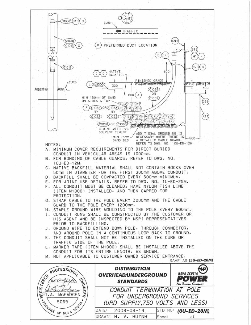
d) Temporary services connecting to an underground supply point shall be in accordance with drawing 8U-ED-40M.
NOTE: Copies of drawings referenced above are included in Appendix C.
12.4 Prefabricated Homes
As with buildings constructed on site, the Customer shall obtain approval from the Supply Authority for the route of the utility supply conductors and the location of the service entrance for prefabricated homes (modular homes, mini homes, etc.) being constructed for a specific building lot.
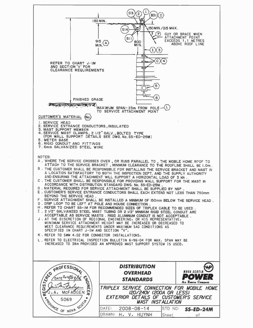
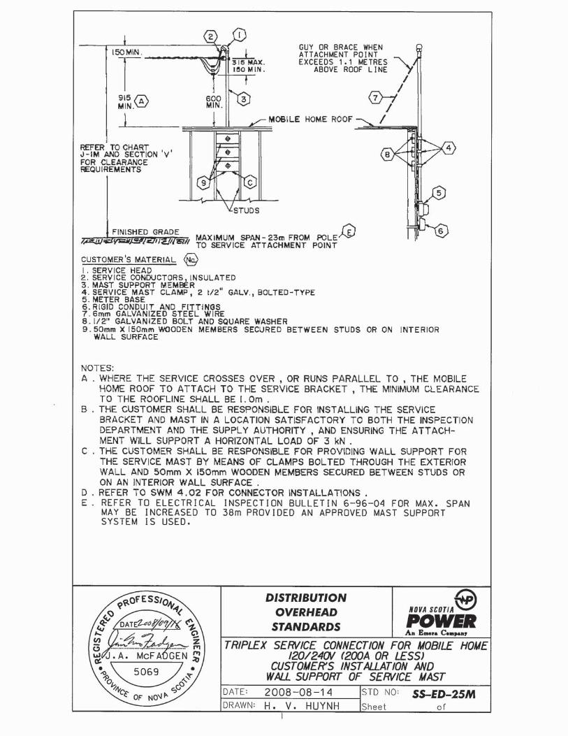
12.5 Mobile Homes
A transportable dwelling unit constructed to be towed on its own chassis.
a) As with buildings constructed on site, the Customer shall obtain approval from the Supply Authority for the route of the utility supply conductors and the location of the service entrance for mobile homes.
b) For the maximum length of service conduit permitted, see clause 12.2 (b) - Service Entrance Disconnect.
c) Service wires supplying one mobile home shall not pass over the roof of any other home.
d) Where the service wire crosses over a mobile home roof, the minimum clearance to the roof shall be 915 mm in accordance with drawings SS-ED-24M and SS-ED-25M.
12.6 Recreational Vehicles:
Service to recreational vehicles shall be considered to be permanent as regards the requirements of the service entrance and all supporting structures. The customer is responsible for the cost associated with the installation of an approved pole or other suitable structure that is acceptable to both the Supply Authority and the Inspection Department, and must be capable of supporting the service entrance equipment.
NOVA SCOTIA POWER INC. UTILITY SERVICE REQUIREMENTS
Page 13
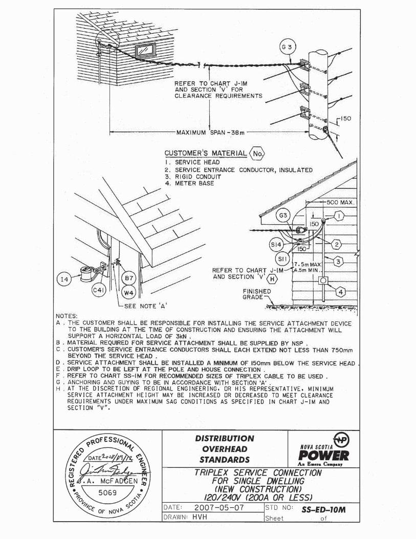
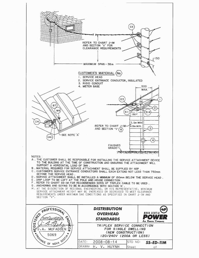
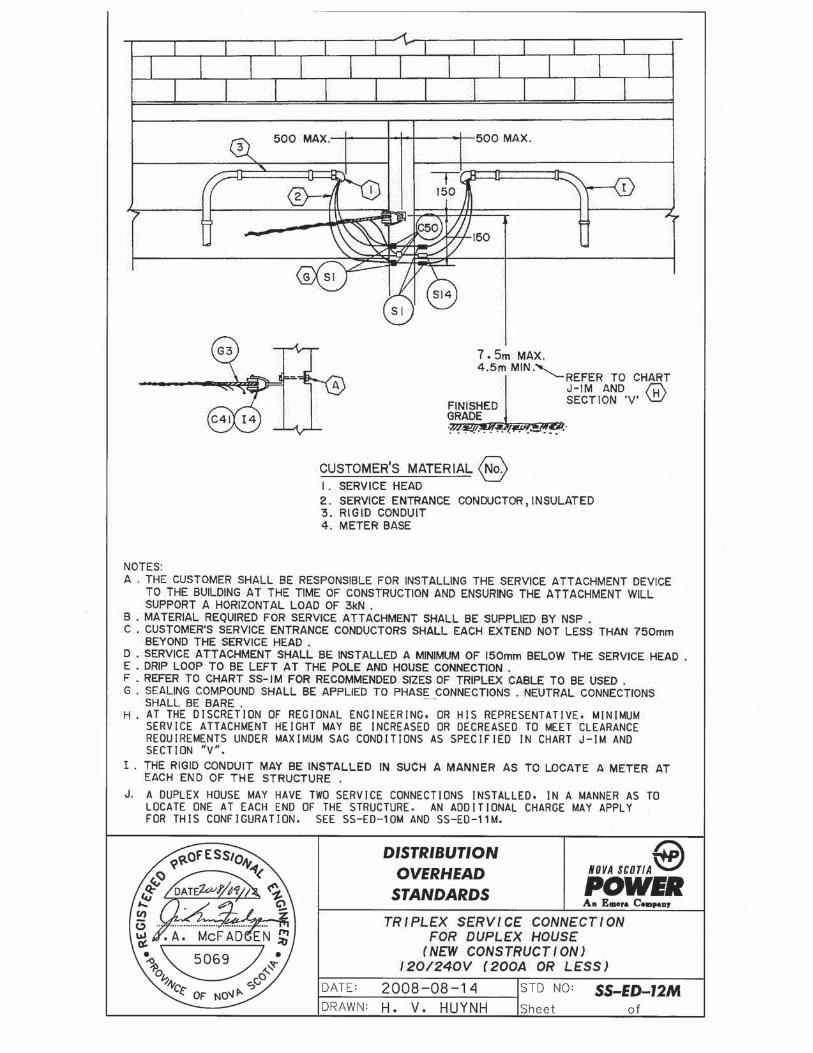
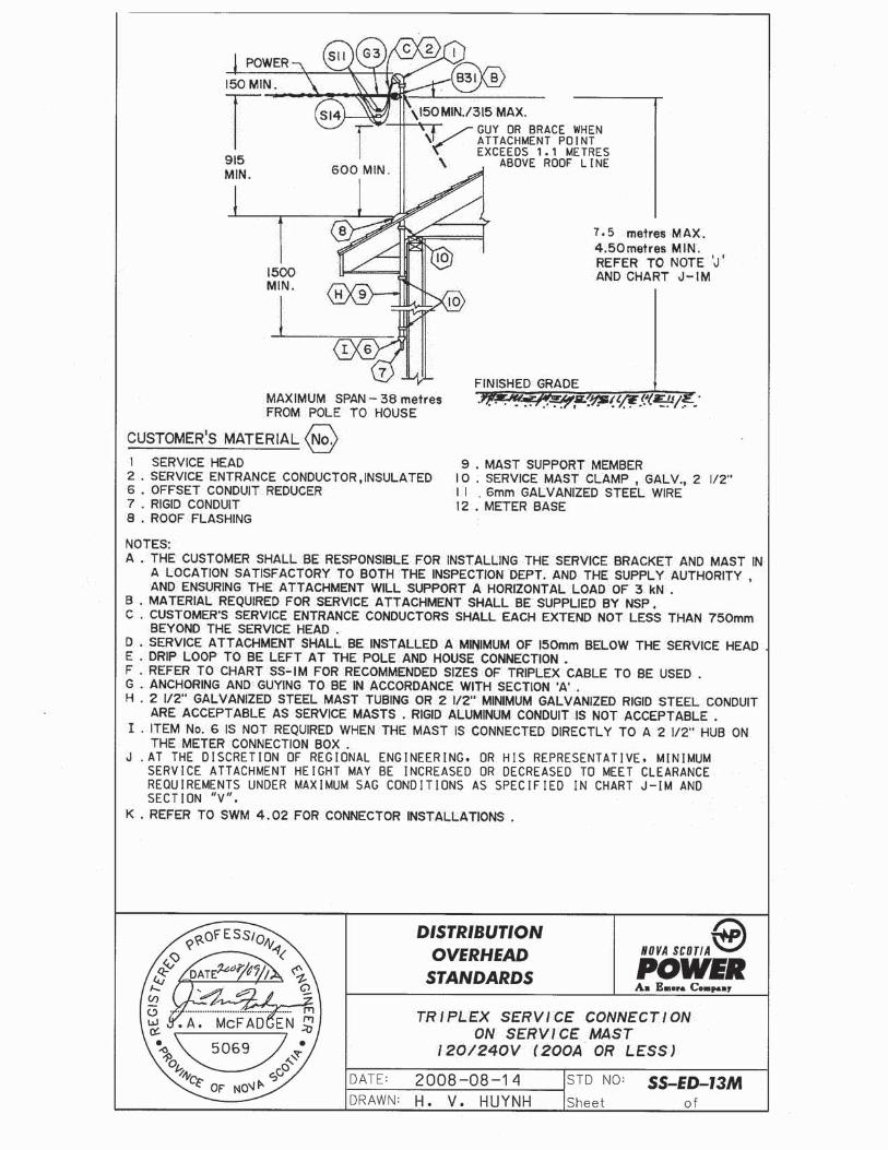
12.7 Utility Supply Conductors Point Of Attachment At Building:
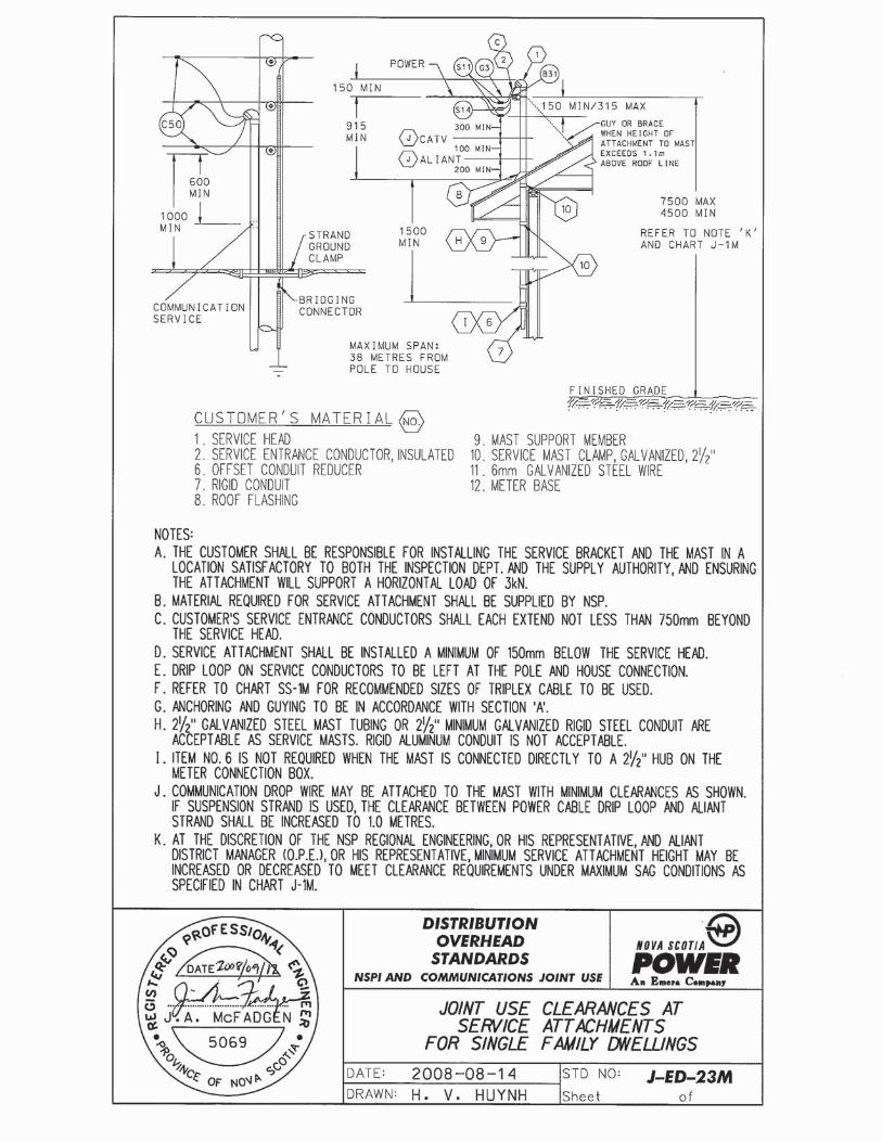
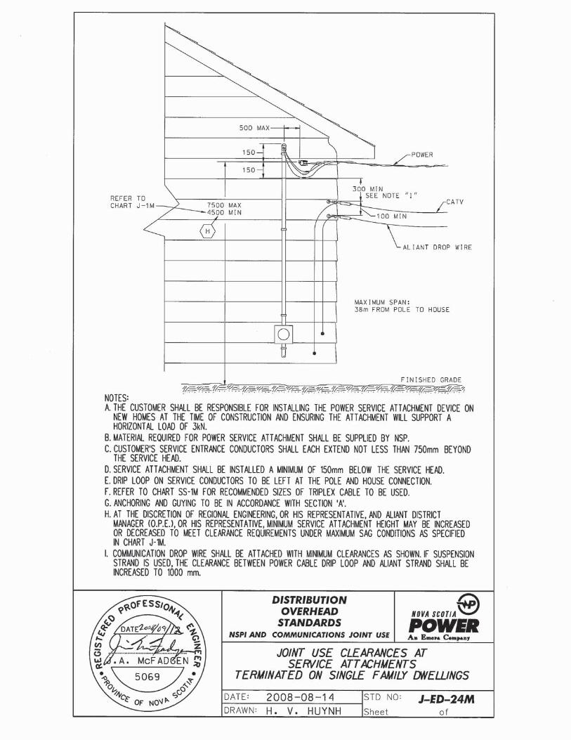
a) The point of attachment at buildings shall be in accordance with the CEC and NSPI drawings SS-ED-10M, SS-ED-11M, SS-ED-12M, SS-ED-13M, SS-ED-14M, J-ED-23M, J-ED-24M as appropriate.
b) The point of attachment shall maintain a minimum conductor clearance of 1.0 meter from windows, doors, fire escapes and porches.
c) The point of attachment shall be such that it allows the utility to maintain a minimum design clearance of 1.0 m horizontal or 2.5m vertical between the utility supply conductors and building surfaces that are readily accessible.
d) Where existing service entrances are upgraded or repairs are made to the service entrance above the meter base, minimum height and clearance requirements as per the CEC and NSPI Standards shall be met.
e) NSPI will supply the attachment device, the customer must install it.
f) If the point of attachment to a service mast exceeds 1.1m above the roof line, then the mast shall be guyed or braced.
12.8 Customer’s Service Stacks And Conduits:
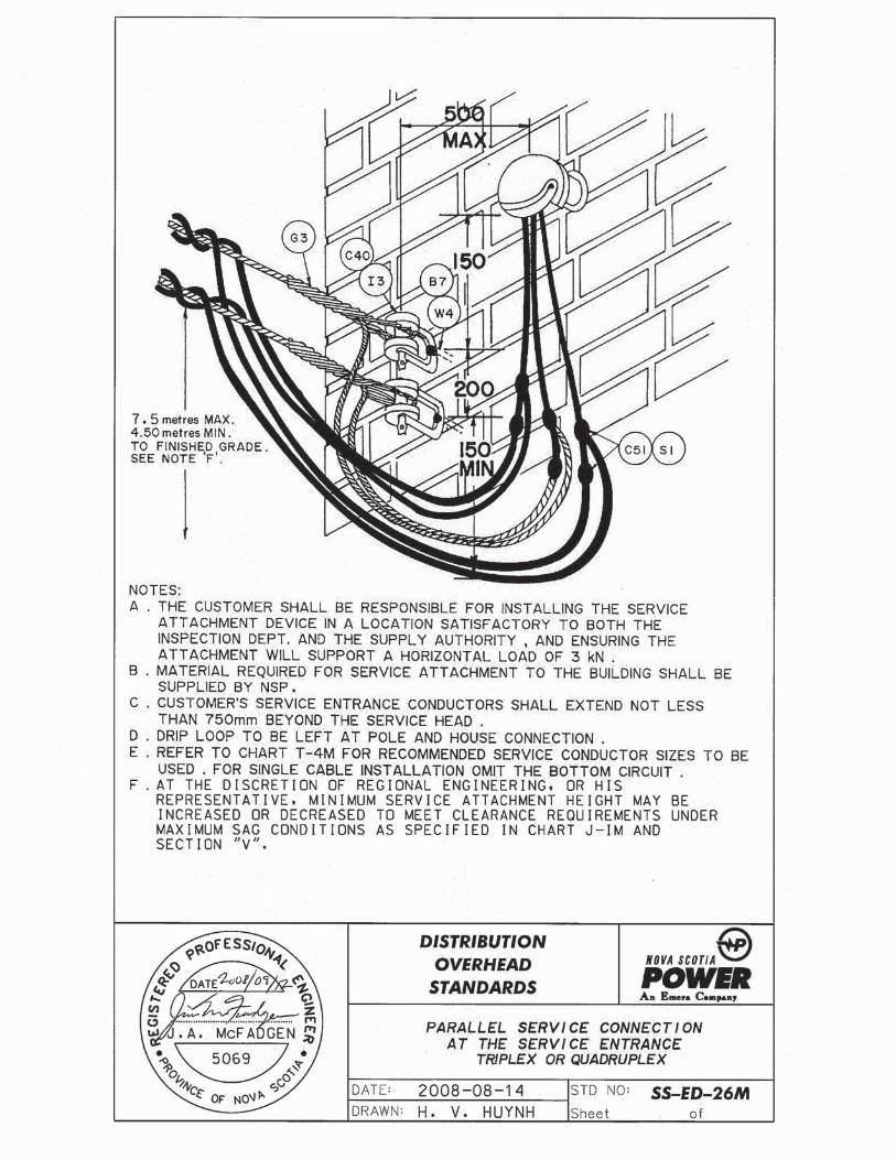
a) The maximum number of service raceways shall not exceed four to any one building.
b) Multiple service weatherheads for a single customer on a building shall be located within 300 mm of each other to allow for connection to a single set of utility supply conductors.
12.9 Service Entrances on Utility Poles:
Service entrances and meters shall only be permitted on utility poles as follows:
a) Service entrance and meter may be installed on a service pole that carries only utility secondary conductors.
b) In the case where a service pole is supporting primary voltage and is dedicated to one customer, then service entrance and meter may be installed on the pole.
NOVA SCOTIA POWER INC. UTILITY SERVICE REQUIREMENTS
Page 14
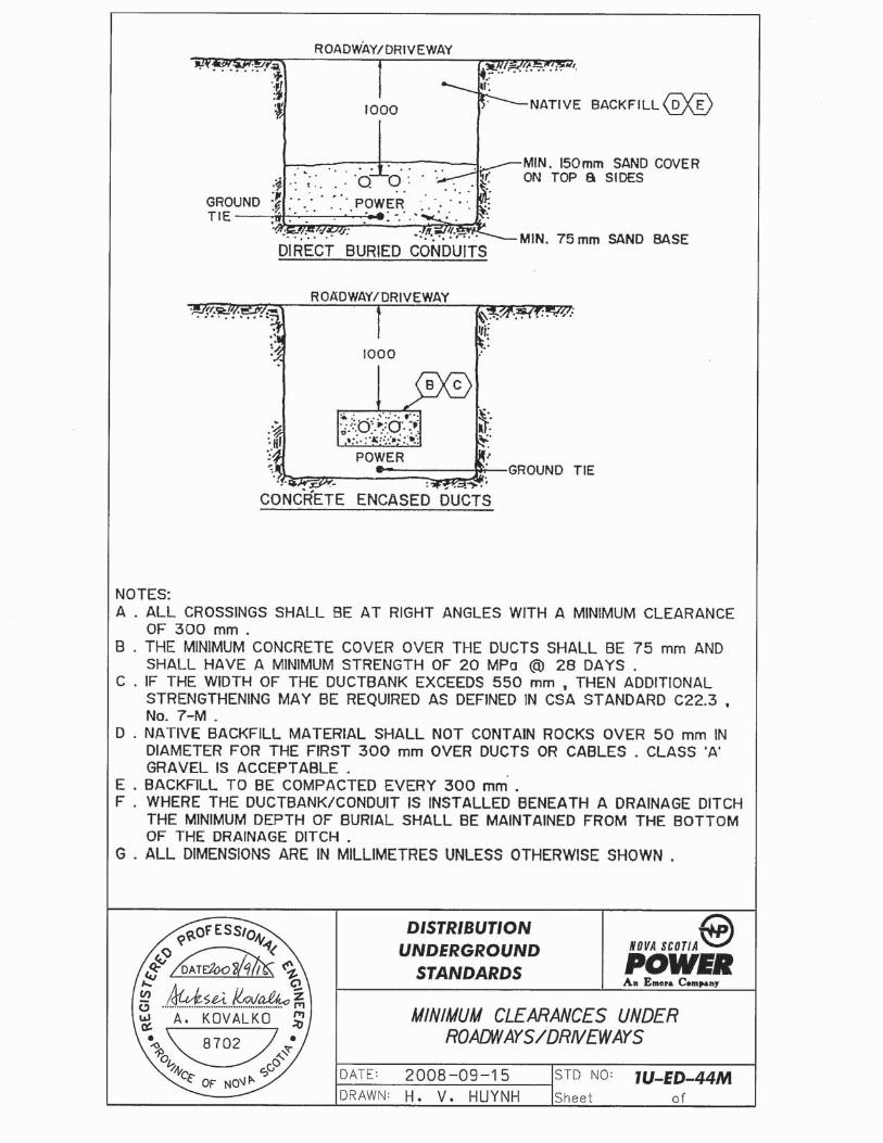
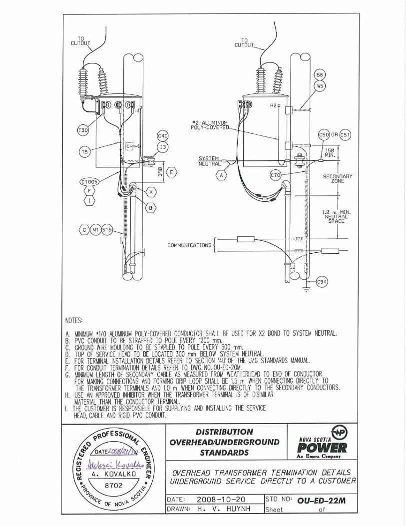
c) On a mainline primary pole, service raceway and length of conductor shall be installed in accordance with drawing OU-ED-22M (meters are not permitted on main line primary poles).
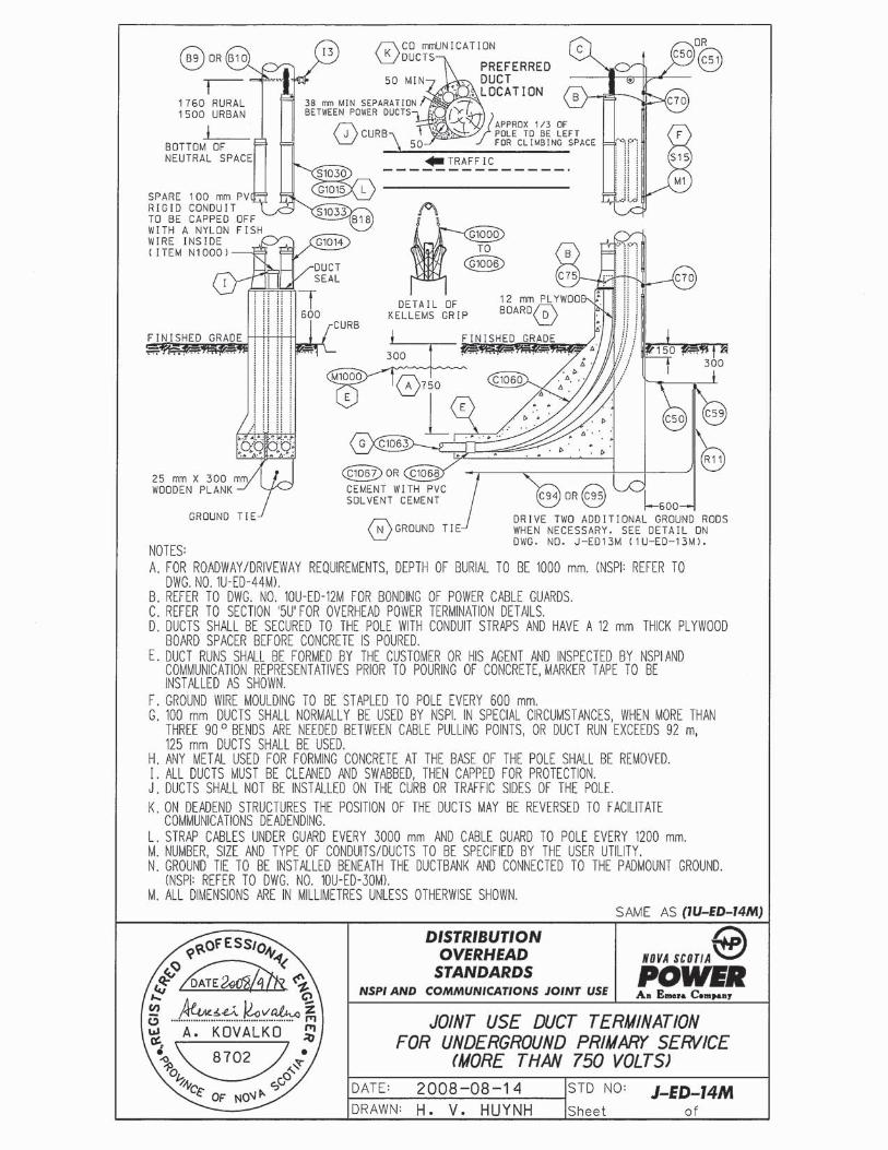
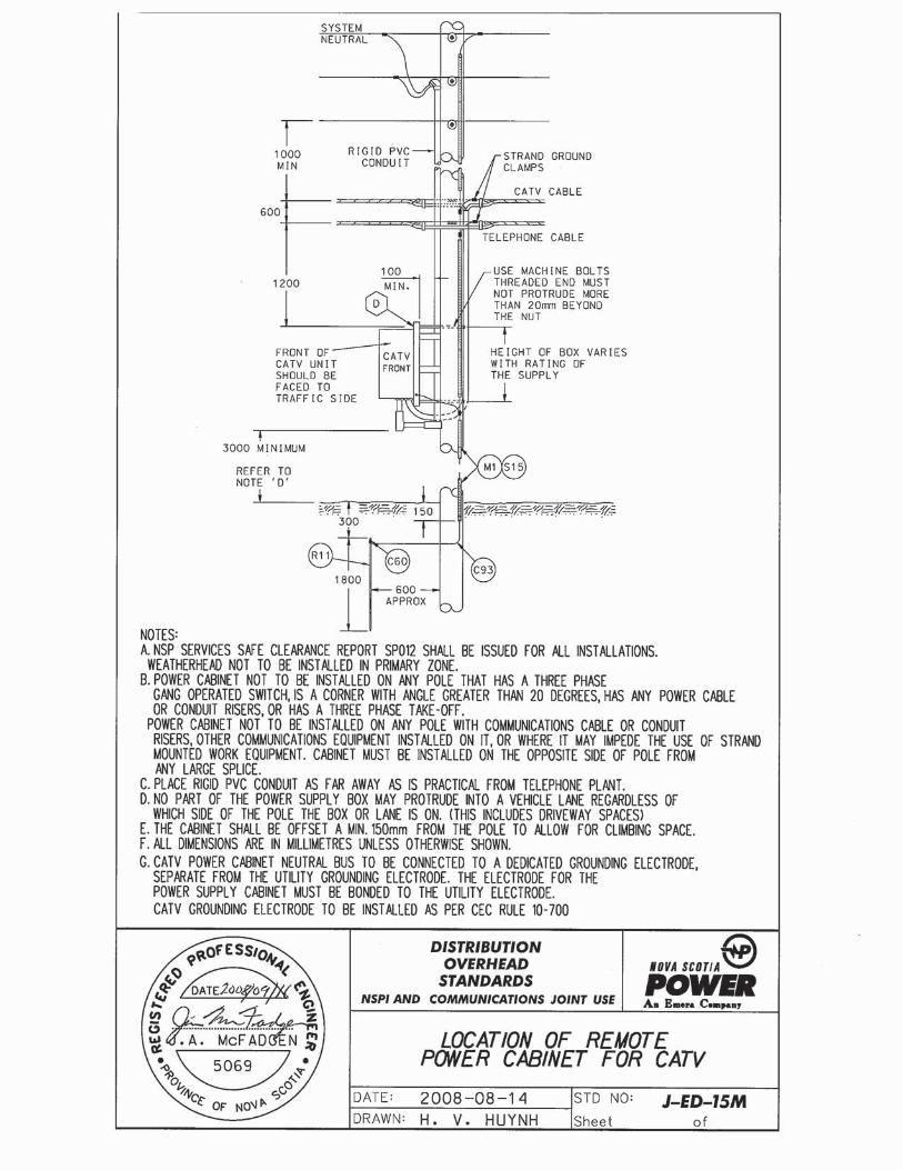
d) CATV power supplies may be installed on utility poles, and shall be in accordance with drawing J-ED-15M.
NOTE: Prior approval of the supply authority is required for installations in accordance with paragraphs (b), (c) and (d) above. Approval shall include a completed Safe Clearances Report, (see Appendix A for an example).
13 SERVICES REQUIRING PRIMARY EQUIPMENT
Some larger facilities will require the installation of a transformer that is too large for a mounting on a single pole and/or a primary line extension. The customer will be referred to the local Engineering or Planning Office for particulars and approval.
All NSPI Standard Drawings referred to in this section are included in Appendix C.
13.1 Policy
NSPI Regulation 2.1 regarding transformer installation states the following:
“When in the Company’s opinion, it is impractical to provide the customer’s electrical requirements from existing Company facilities the customer must, on the request of the Company, provide suitable transformer(s) space on the customer’s premises for the necessary transformers. The type and location of primary service equipment must be approved by the Company for each installation”.
The space for the primary service equipment may be in the form of a suitable room inside the building or a designated space on the property outside the building.
13.2 Customer Responsibilities
13.2.1 The customer shall provide NSPI with site drawings and an estimate of connected electrical load at the earliest possible stage of planning. This will permit the Utility to determine an acceptable method of service and point of supply. It will also provide lead time for the ordering of electrical equipment.
NOVA SCOTIA POWER INC. UTILITY SERVICE REQUIREMENTS
Page 15
13.2.2 The customer shall provide, as soon as possible, electrical plans for the buildings and other facilities/structures which are to be submitted to the Inspection Authority and accepted before service arrangements can be finalized.
13.2.3 The following requirements must be met before temporary or permanent service connection can be provided:
(a) A building permit must have been obtained from the applicable municipal authority.
(b) Authorization must be given by the electrical inspection authority.
(c) An electric service contract must be completed by the party accepting responsibility for the electric service account. A security deposit may be required as part of the service contract.
13.2.4 The customer shall be responsible for the additional expense of any temporary service required for construction power. Arrangements must be made with NSPI for the connection of a temporary service.
13.2.5 The customer will be required to make a capital contribution if the service requirements exceed the Utility’s normal service allowance. The allowance consists of 92 metres of overhead line extension or 46 meters of high voltage underground cable. Payment of the contribution will be required before electric service can be provided.
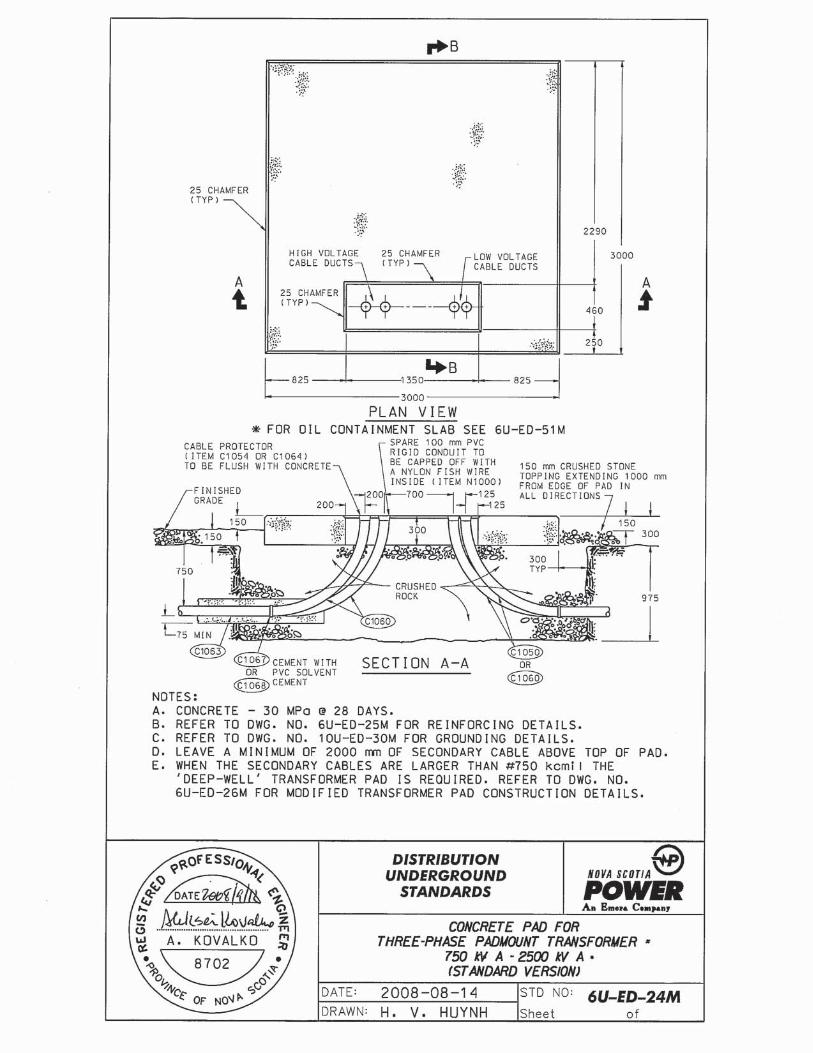
13.2.6 The customer shall provide, own and maintain all secondary voltage electrical equipment. This includes the electrical cables from the customer’s main disconnect switch to the padmounted transformer and the connectors required for the secondary terminations on the transformer (see Appendix D). The secondary cables shall be installed by the electrical contractor such that the end of each secondary cable extends a minimum of 2 metres above the transformer base. This is required to ensure sufficient cable for connection to the transformer. The connection of secondary cables to the transformer will be done by NSPI.
13.2.7 All customer-owned electrical equipment must be inspected and approved by the appropriate inspection authority.

NOVA SCOTIA POWER INC. UTILITY SERVICE REQUIREMENTS
Page 16
13.2.8 The customer shall provide, own and maintain the civil structures necessary to support the high voltage electrical equipment. The civil structures generally consist of a concrete base for the padmounted transformer and a concrete encased ductbank for the high voltage cable. The ductbank and the transformer base must be inspected and approved by NSPI.
13.2.9 The customer shall provide NSPI with easements pertaining to the ductbank and transformer installations which will allow the Company to install and maintain the primary service equipment.
13.3 NSPI Responsibilities
13.3.1 NSPI will normally supply, own and maintain the high voltage cable, complete with terminations, and the padmounted transformer.
(In certain cases, the customer may arrange or be required to supply the high voltage cable and the transformer. These situations will be rare and will be dealt with on an individual basis.)
13.3.2 Connection of all cables to the transformer unit will be performed by NSPI.
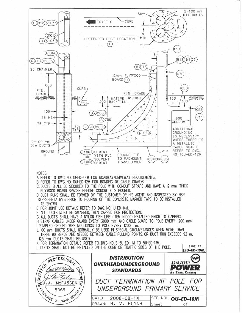
13.4 Duct Banks
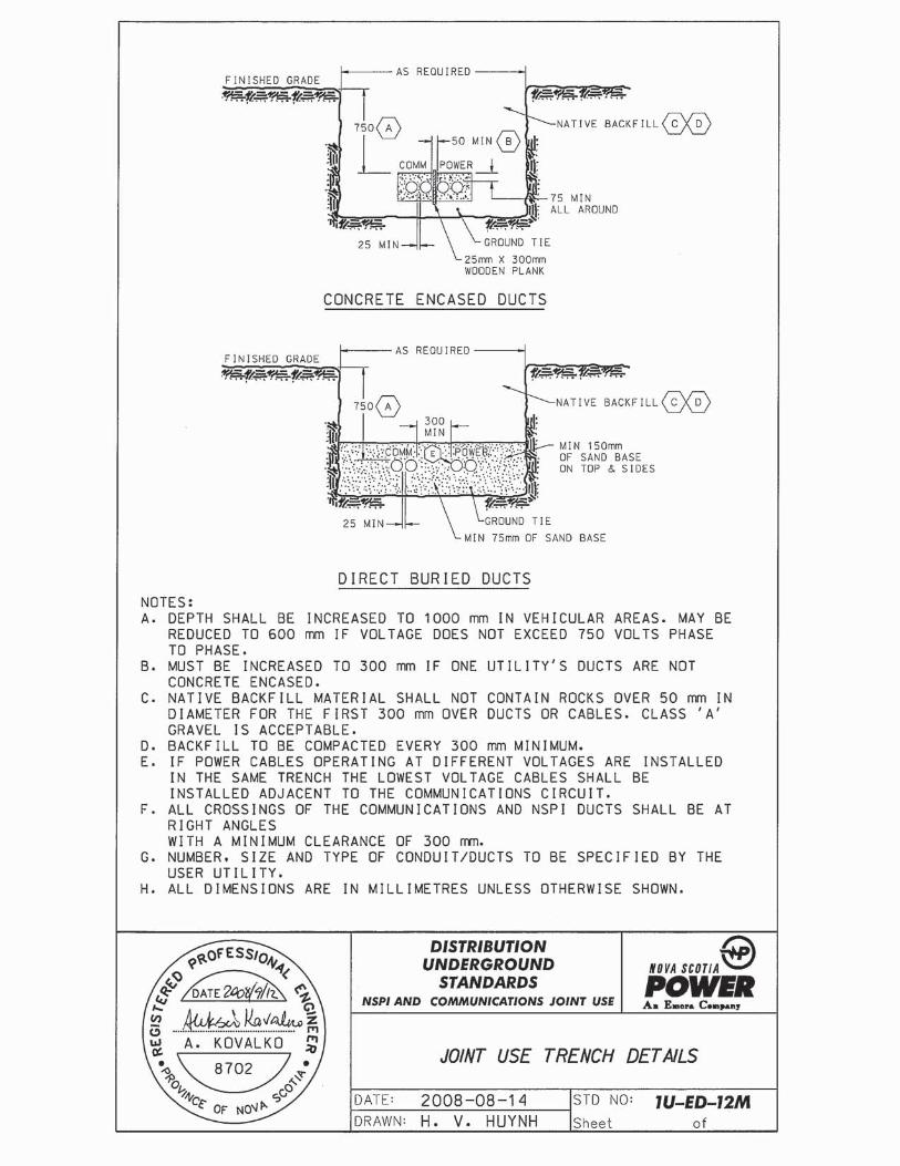
The customer shall provide a suitable underground ductbank as shown on Dwg. 1U-ED-12M and Dwg. 1U-ED-14M. If telephone ducts are not required, they may be eliminated along with the wooden plank separation. Drawing 5U-ED-10M shows details of the non-joint use duct bank. Appendix 5 contains an approved hardware and materials list to be used in conjunction with the drawings in this document. Item numbers shown in circles or ovals on the drawings are cross-referenced in this listing to the appropriate description and part numbers.
The following specifications must be met;
13.4.1 All ducts and fittings must be approved by a recognized Certification Agency. (e.g., CSA or ULC)
13.4.2 All Primary Ducts are to be concrete encased unless otherwise specified by NSPI. Secondary ducts may be direct buried.
NOVA SCOTIA POWER INC. UTILITY SERVICE REQUIREMENTS
Page 17
13.4.3 Ducts must be supported by approved spacers. Wire or metal ties are not to be used to support the electrical ducts.
13.4.4 Duct risers at poles shall face away from the flow of vehicular traffic and shall not be installed on the curb or sidewalk side of the terminal pole.
13.4.5 Ducts shall be carefully installed and all joints are to be glued unless the duct system is specifically designed for friction or snap fit. Such duct systems must be preapproved by NSPI Engineering. Foreign material is to be kept out of the ducts.
13.4.6 Long sweep 90 degree rigid PVC or heavy wall FRE bends shall be used at both the pole and the concrete pad. PVC type DBII or FRE may be used for the remainder of the duct run.
13.4.7 The standard duct size shall be 100 mm. When the equivalent of more than 3 90 degree bends are required between pulling points, or the duct run is in excess of 90 metres in length, 125 mm duct shall be used.
13.4.8 The primary ductbank and concrete pad are to be formed and inspected by the Utility before pouring any concrete. In joint use applications representatives from both NSPI and Aliant must be called for inspection purposes. A 75 mm envelope of concrete is required around the ductbank.
13.4.9 All ducts are to be swabbed and a 4 mm polyethylene fish line installed in each duct. Ducts are to be sealed with proper caps at both ends.
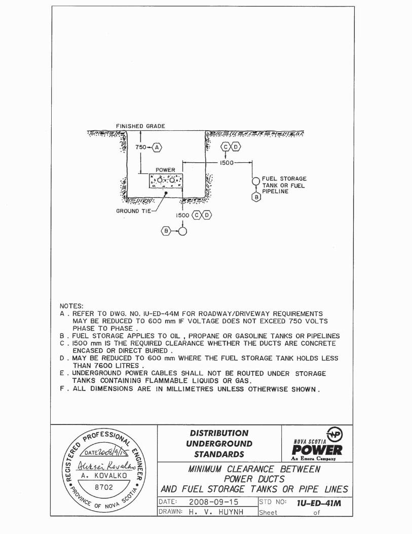
13.4.10 A 1.5 m separation shall be maintained between the ductbank and a fuel storage system or a steam line. See Drawing NO. 1U-ED-41M for details on the required separation between ductbanks and various underground structures.
13.4.11 A 1.5 m minimum horizontal separation shall be maintained between a high voltage ductbank and a swimming pool.
13.4.12 A ductbank shall not run directly above or below other underground systems such as water, sewer, or communications. An electrical ductbank may cross other underground systems at right angles as long as a minimum separation of 60 mm is maintained.
NOVA SCOTIA POWER INC. UTILITY SERVICE REQUIREMENTS
Page 18
13.4.13 Under some conditions, it will be necessary to place some reinforcing steel in the ductbank. Typical examples include fluid or unstable soil conditions or where a ductbank passes under a retaining wall or building foundation. Details of the proposed installation must be approved by NSPI.
13.4.14 At the riser pole, there is to be a 12 mm spacer between each duct and the pole.
13.4.15 Marker tape approved by NSPI shall be installed above all primary ductbanks. The marker tape shall be located 300 mm below finished grade. Installation of this tape must be verified by NSPI before it is covered.
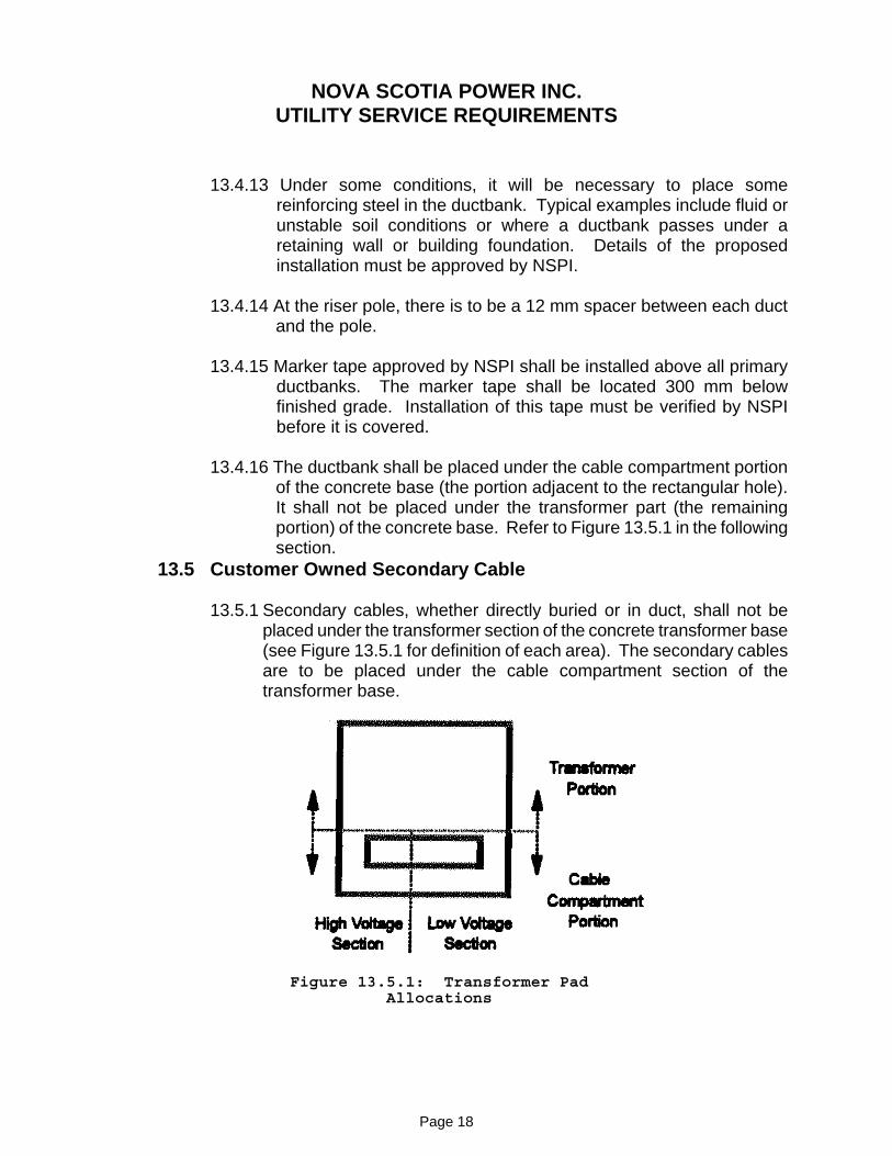
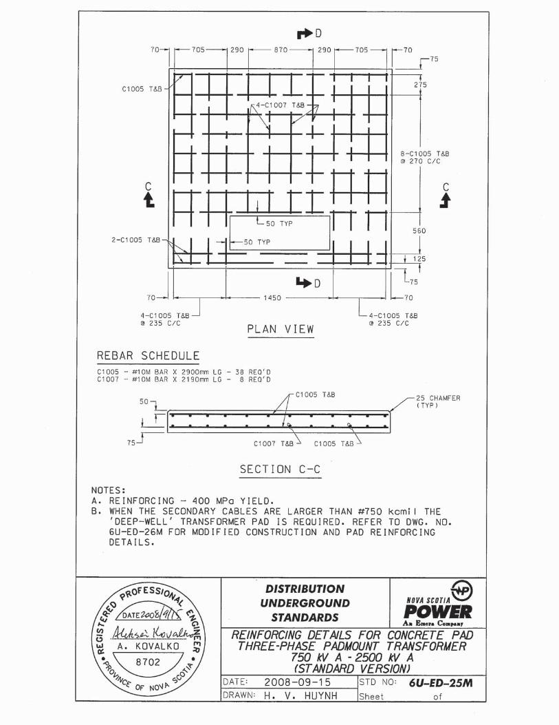
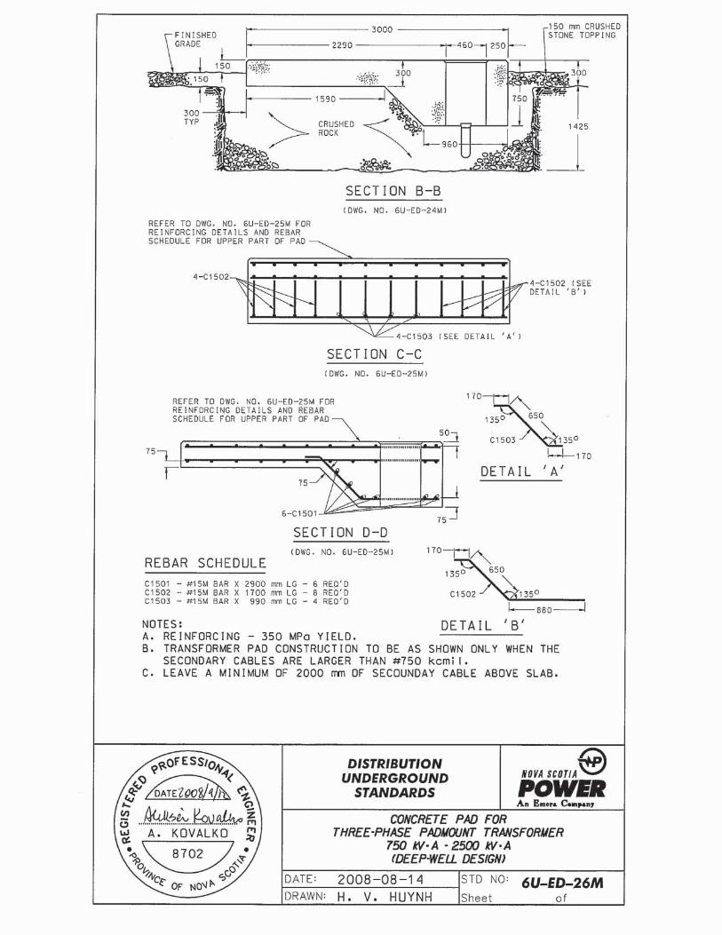
13.4.16 The ductbank shall be placed under the cable compartment portion of the concrete base (the portion adjacent to the rectangular hole). It shall not be placed under the transformer part (the remaining portion) of the concrete base. Refer to Figure 13.5.1 in the following section.
13.5 Customer Owned Secondary Cable
13.5.1 Secondary cables, whether directly buried or in duct, shall not be placed under the transformer section of the concrete transformer base (see Figure 13.5.1 for definition of each area). The secondary cables are to be placed under the cable compartment section of the transformer base.
Figure 13.5.1: Transformer Pad Allocations
NOVA SCOTIA POWER INC. UTILITY SERVICE REQUIREMENTS
Page 19
13.5.2 Secondary cables are not to be installed in the high voltage section of the transformer.
13.5.3 Secondary cables are to be connected to the transformer using approved compression lugs (see Appendix 4). The compression lugs are to be supplied by the customer and installed by NSPI. NSPI will supply the stainless steel connection hardware.
13.5.4 Permanent secondary cables are not to be energized or used for temporary service without permission from NSPI.
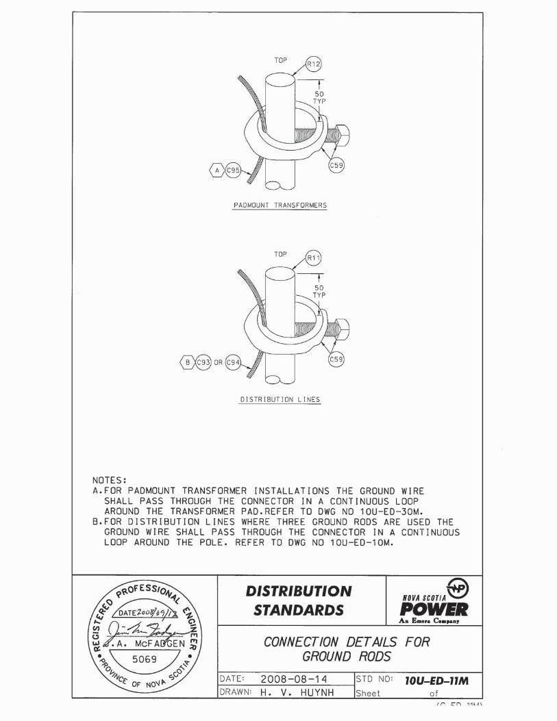
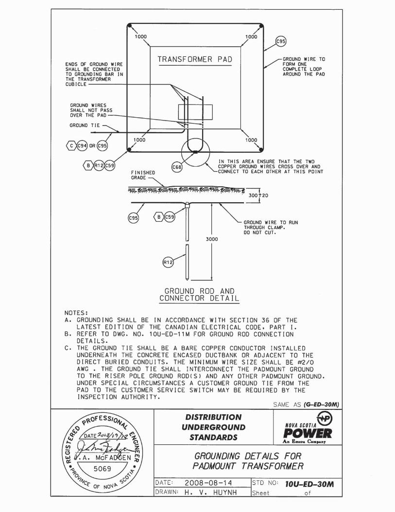
13.6 Ground Tie
The customer shall provide a ground tie between the padmounted transformer and the riser pole (see Drawing No. 1U-ED-12M and 1U-ED-14M). The ground tie shall be a bare copper conductor installed beneath the concrete ductbank. It may also be installed immediately adjacent to the ductbank (on either side). When installed under the ductbank, it shall be inspected by NSPI prior to pouring the concrete for the ductbank. When installed beside the ductbank it shall be verified by NSPI prior to backfilling the trench. NSPI will connect the ground tie to the riser pole ground rod.
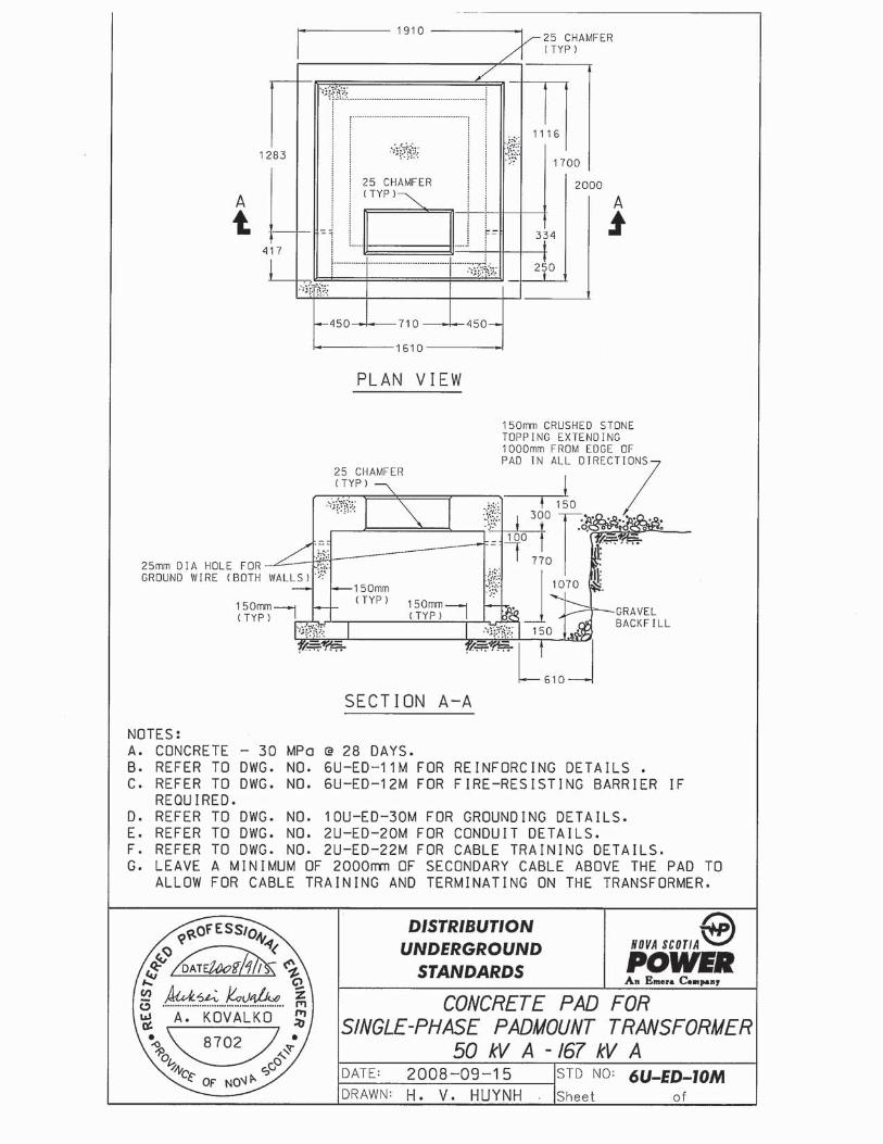
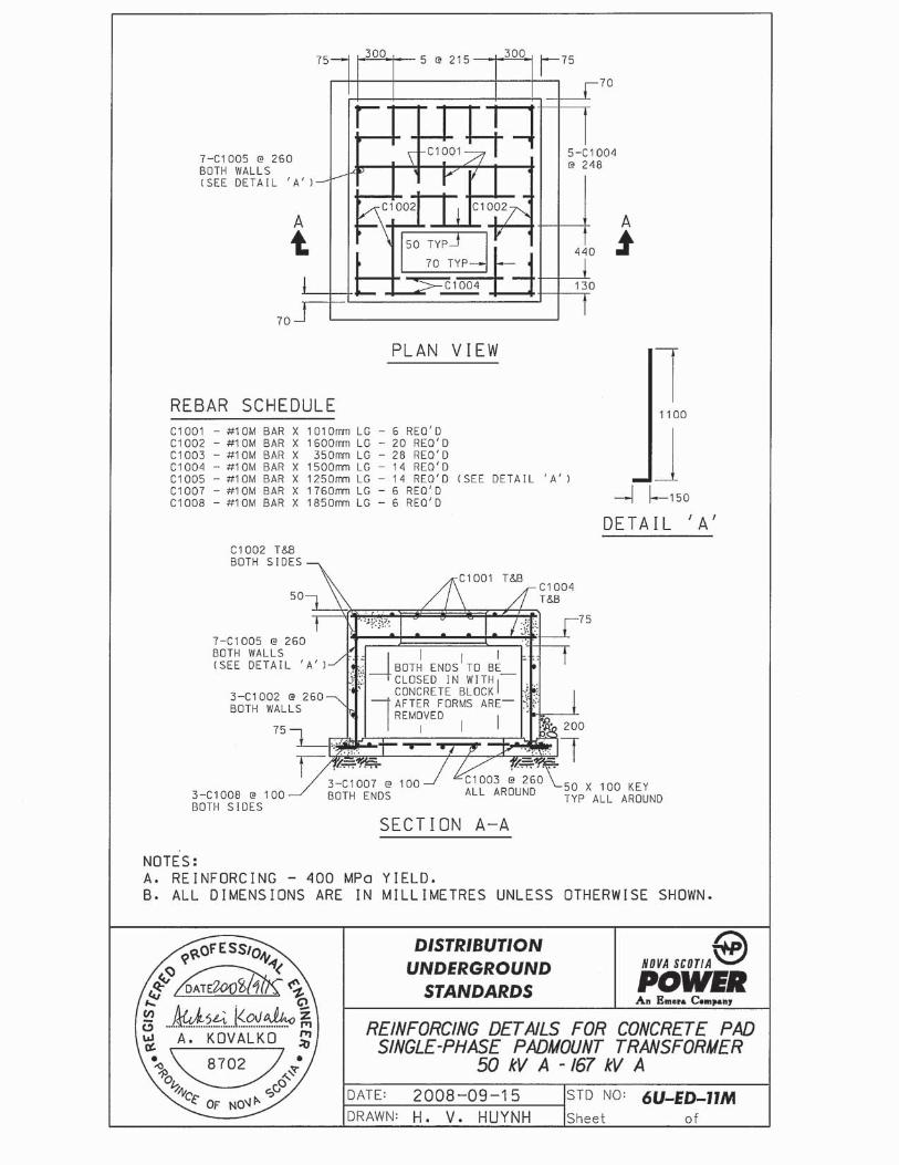
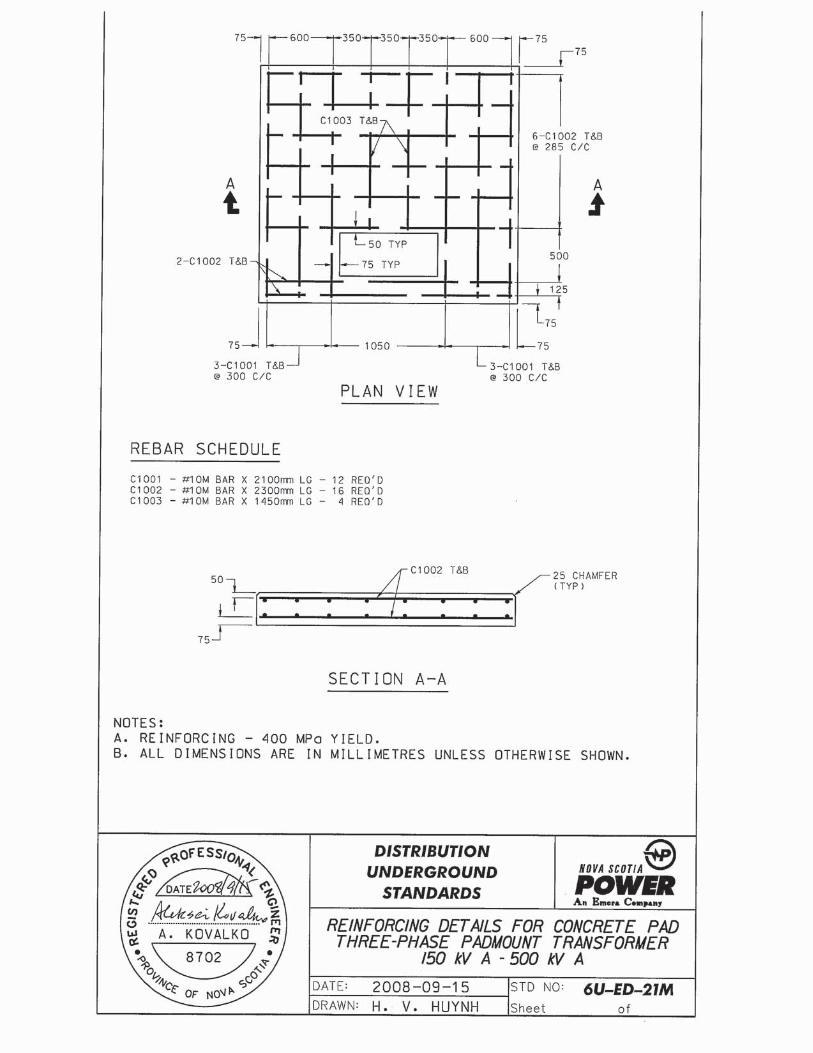
13.7 Concrete Transformer Base
Where a padmounted transformer is required, the Customer shall contact the Utility, and will be referred to the Engineering Department for design and approval requirements regarding transformer pad location and construction standards, trenching and duct installation details, grounding, concrete specifications, cable installation guidelines, etc.
The customer shall provide a suitable concrete base for the padmounted transformer. The base shall be constructed to NSPI specifications using the drawings found in this document. NSPI will select the appropriate transformer size based on estimated load information provided by the customer and other pertinent factors.
Section 13.8 of this bulletin contains a Transformer Pad Selection Guide which references the drawings pertaining to each transformer base size.
A fire-resisting barrier or vehicular protection may be required in certain circumstances. Section 13.9 outlines the requirements for fire-resisting barriers. Section 13.10 outlines the requirements for vehicular protection.
NOVA SCOTIA POWER INC. UTILITY SERVICE REQUIREMENTS
Page 20
13.7.1 The transformer base shall be inspected by NSPI during construction and approval given before any backfilling or pouring of concrete.
13.7.2 The concrete base shall be located in an area that is permanently accessible by NSPI maintenance vehicles. It shall be located within 3 m of a roadway, parking lot, or other reasonable means of access.
13.7.3 The area surrounding the transformer shall be kept clear of any obstructions (bushes, trees, posts, etc.) for a distance of one meter out from all sides of the concrete base.
13.7.4 Grounding around the concrete base shall be provided by the customer in accordance with Drawings 10U-ED-11M and 30M. Ground rods are not to be installed under the concrete base. The grounding installation must be inspected by NSPI before it is covered over.
13.7.5 The use of pre-cast transformer bases is acceptable if they have been constructed in accordance with NSPI specification and have been approved by NSPI.
13.7.6 No padmounted transformer shall be installed on a pad until the concrete has been allowed to set for a minimum of forty-eight hours.
13.8 Fibreglass or Composite Transformer Base
Notwithstanding clause 13.7, the customer may provide a suitable base for the padmounted transformer that is constructed of fiberglass, plastic or a composite material. Approval of NSPI Distribution Standards Department is required before purchase or installation.
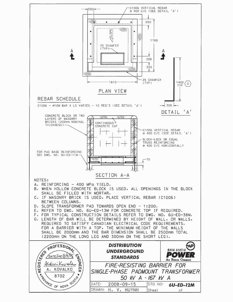
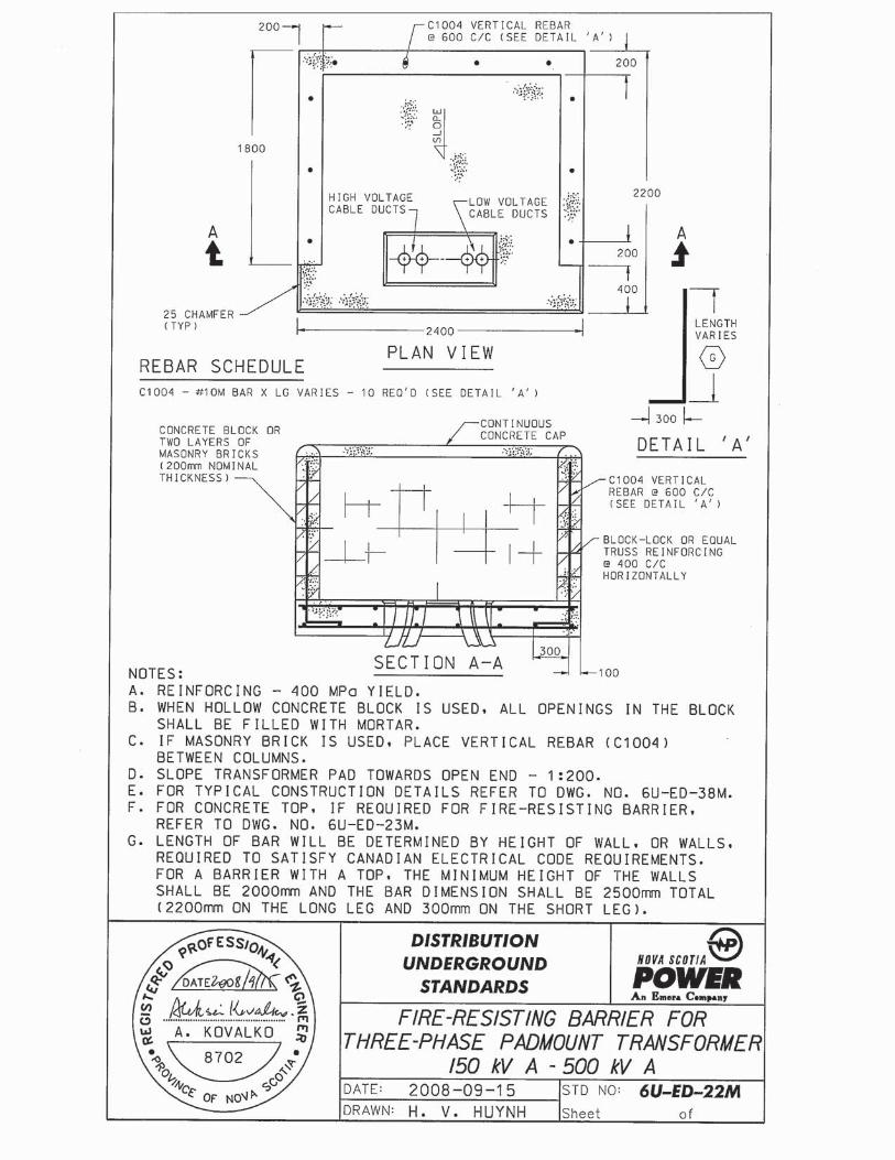
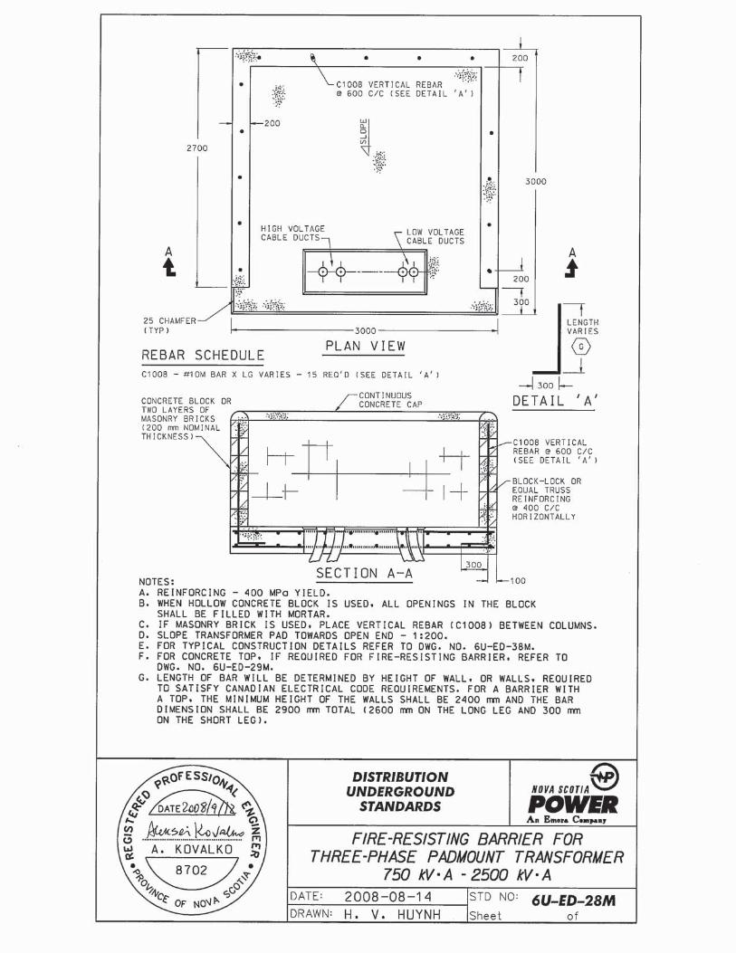
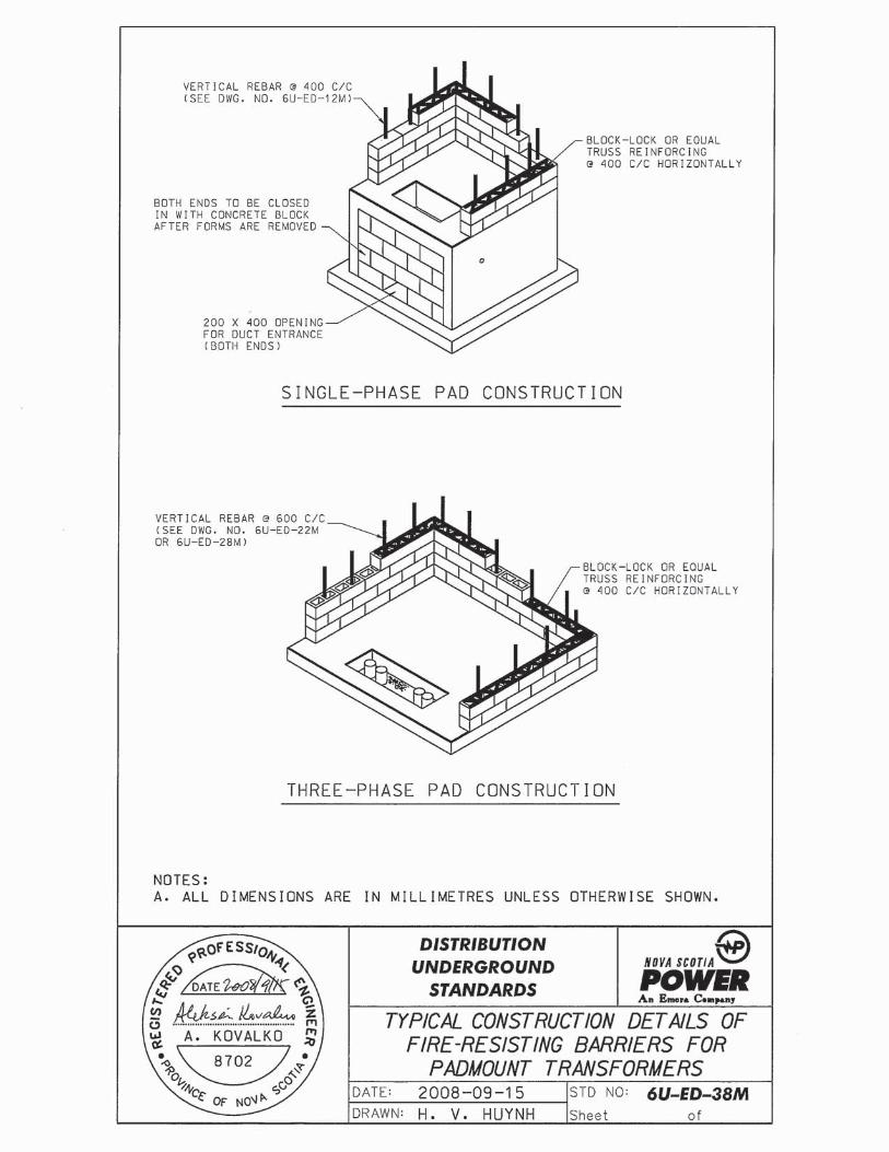
13.9 Fire-Resisting Barriers
A fire-resisting barrier shall be required if a transformer will be installed within 3 meters of any combustible surface or material on a building or within 6 meters of any door, window, or ventilation opening on a building. The fire-resisting barrier must be constructed between the transformer and the door, window, ventilation opening or combustible surface.
In case of dispute, the local Inspection Authority in conjunction with the Supply Authority shall determine the barrier requirements.
NOVA SCOTIA POWER INC. UTILITY SERVICE REQUIREMENTS
Page 21
13.9.1 The fire-resisting barrier shall be constructed of concrete block or two layers of masonry brick.
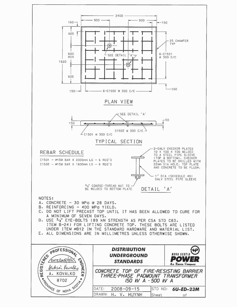
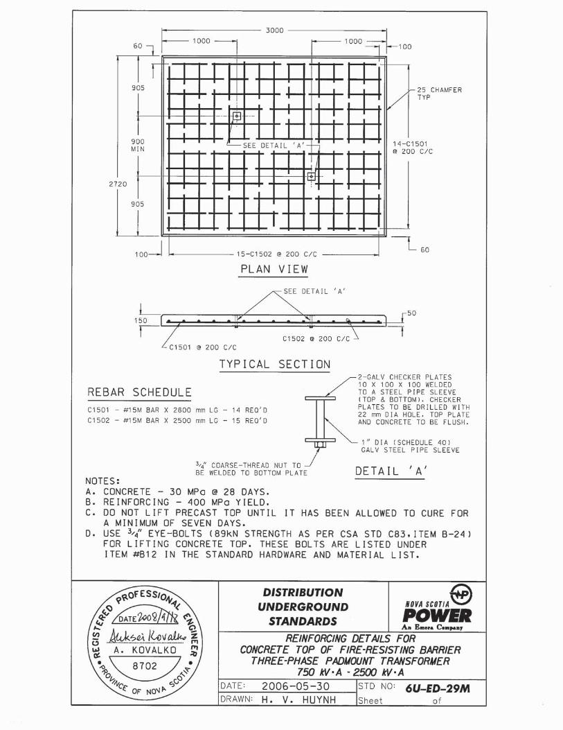
13.9.2 The fire-resisting barrier shall consist of one, two, or three walls, with or without a concrete top.
13.9.3 When only one or two walls are being constructed, the height of the barrier wall shall not exceed 1.9 m. If circumstances require a height in excess of 1.8 m, then a three-walled structure complete with a concrete top shall be constructed instead.
13.9.4 Where a concrete top is installed, a minimum clearance of 150 mm shall be maintained from the top of the transformer to the underside of the concrete top. Unless otherwise notified by NSPI, the minimum height of the walls shall be as follows: for single phase transformers the minimum height of the three walls shall be 2.0m; for three-phase 150 – 500 kVA transformers the minimum height shall be 2.0 m; and for three-phase 750 – 2500 kVA transformers the minimum height shall be 2.4 m.
13.9.5 Where a three-walled barrier is constructed, the transformer cable compartment must face the open side of the barrier structure as shown in the drawings. Therefore the transformer pad must be oriented with the cable compartment (and thus the opening in the fire barrier) away from the building, combustible material, or windows, doors, etc., in order to satisfy the requirements of the electrical code regarding fire-resisting barriers.
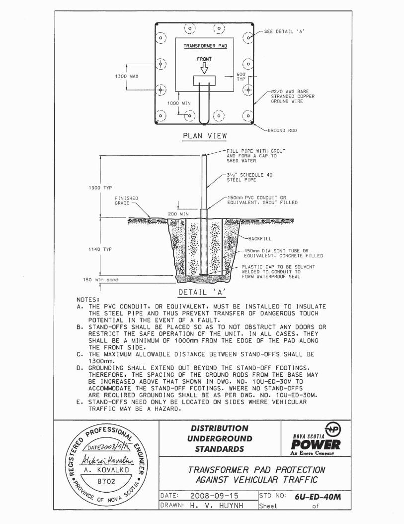
13.10 Mechanical Protection
Vehicular protection is required to protect the transformer from being accidentally hit by vehicles. This is most commonly applied for transformers close to driveways, parking lots, or loading bay areas. If it is judged by NSPI that the transformer would be in danger of being hit by traffic, protection will be required on one or more sides. This shall be constructed as shown on Drawing No. 6U-ED-40M.
NOVA SCOTIA POWER INC. UTILITY SERVICE REQUIREMENTS
Page 22
13.11 Definition of Backfill Materials
The transformer base (or pad) drawings refer to several types of backfill materials.
1. Gravel backfill – shall consist of well graded, clean granular material containing no material larger than 50 mm in size and shall meet the requirements of gravel – Class C as specified by the Department of Transportation.
2. Crushed rock backfill – shall consist of 20 mm clear crushed rock. Crushed rock backfill shall be used as a base for certain construction, as specified.
3. Crushed stone topping – shall consist of angular shaped, hard, igneous rock, crushed, screened and washed. Soft rock, shale, or slate is not acceptable. The product shall be of uniform quality throughout and shall be free of flat, elongated, round or other objectionable pieces. No earth, sod, silt, clay or any foreign or vegetative matter shall be allowed in this material. The purpose of the crushed stone topping is to reduce electric shock hazard and provide a stable working surface around the padmounted transformer.
13.12 Primary Line Extensions
Individual customers are entitled to a 92 metre overhead line extension credit. If required, NSPI will determine the point of attachment at both the customers’ point of connection and NSPI plant. Any length over this amount will require a capital contribution from the customer.
Customers must contact the NSPI to determine the suitability of any lines near the site of the new service. Not all lines are suitable for direct attachment of customers. NSPI must determine which line(s) are suitable for the installation being considered. Site planning by the customer should not assume the point of connection or routing for primary lines as this is the responsibility of NAPI.
Refer to NSPI regulation 2.6 on line extensions.
NOVA SCOTIA POWER INC. UTILITY SERVICE REQUIREMENTS
Page 23
14 METERING
General All meter installations shall comply with NSPI Metering Standards. Existing non-
standard installations shall be changed to conform with these standards when alterations are made to the service.
All new and upgraded three phase 4 wire meter installations, self-contained or transformer rated shall require 3 element meters to be installed. Three phase 2 ½ element meters are only used for replacement of existing 2 ½ element meters.
Specialized metering installations not covered by these standards shall be developed by Regional Engineering and approved by Meter Services.
14.1 Electrical Contractor’s Responsibilities
1) The electrical contractor shall supply and install all meter sockets, cabinets, conduit (for CT & PT secondary leads as required) and current transformers lugs.
2) The contractor is responsible for the installation of transformers in metal enclosures as per the requirements of Canadian Electrical Code for enclosures for instrument transformers (Rule 6-404). Enclosures shall have provision for sealing.
3) The contractor is responsible for connections to the primary side of current transformers.
NOTE: #1 NSPI will supply all revenue class potential and current transformers.
NOTE: #2 NSPI will supply and install colour-coded secondary wiring from current transformers to meter socket and wiring to the primary and secondary side of potential transformers.
14.2 Meter Locations
1) The Meter and associated metering equipment shall be in locations satisfactory to both inspection and supply authority (refer to Canadian Electrical Code Part I, Rules 6-402 and 6-408, and metering standards MS 7.0). The center of the meter shall not be higher than 1.8 m or lower than 1.4 m from the floor or ground level. Meters and metering equipment may be placed outdoors if they are of weatherproof construction or in weatherproof enclosures.
NOVA SCOTIA POWER INC. UTILITY SERVICE REQUIREMENTS
Page 24
2) Normally meter sockets are to be located on the outside of the building. Utility approval is required for meter sockets to be located inside of buildings with the exception of multiple occupancy buildings with more than four meter positions.
3) Meters shall not be located in bins, clothes closets, bathrooms, stairways, high ambient temperature room, dangerous or hazardous locations, or in any similar undesirable places.
4) For multiple meter installations, as in apartment buildings, office buildings, industrial complexes, etc., the meters shall be conveniently grouped and readily accessible to Meter Readers and Installers during normal business hours.
5) A clear working space of 1.0 m minimum must be provided in front of all meter panels, free of any temporary or permanent obstruction. Passageways and working space around electrical equipment shall not be used for storage and must be kept free from obstruction. (Canadian Electrical Code, Part I, Rules 2-300 through 2-322 deal with these and related items).
6) Every meter shall be installed in a level position and solidly fixed to a wall or other support supplied by the customer, free from excessive vibration. If the meter location proves to be susceptible to vandalism or frequent breakage by other means, a protective enclosure shall be installed at the customer’s expense.
7) When a customer requires a recessed wall installation, adequate room must be provided to install/remove meters and faceplate of the meter base.
8) For temporary service enclosures the meter base shall be installed on the outside of the weatherproof box. (Ref. Electrical Inspection Bulletin B-76-008)
14.3 Instrument Transformers – 0 to 600 volts
1) NSPI will supply the necessary Instrument Transformers; however, the contractor must arrange to have them installed at his expense at the factory or in the field. Refer to Metering Standard MS 4.0 for standard layouts.
2) In the case of factory-built custom switchgear, space is to be provided for instrument transformers and test blocks which are readily accessible for inspection; the compartment or enclosure for instrument transformers must have provision for sealing.
NOVA SCOTIA POWER INC. UTILITY SERVICE REQUIREMENTS
Page 25
3) The instrument transformers are to be electrically connected on the load side of the service box immediately after customer main service switch (C.E. Code Part I, Rule 6-402[2]).
14.4 Secondary Wiring
1) Electrical raceway shall be supplied and installed by the contractor from instrument transformer cabinets or primary metering equipment to meters in minimum sizes noted below: a) Single phase service 2 & 3-wire meter, 20 mm (3/4”). b) Three phase four-wire service, 25 mm (1”).
2) The raceway run shall be as short as practical; however, no run may exceed 30 m or contain the equivalent of more than three 90-degree bends.
3) All meters, meter sockets, metal raceways, cabinets, etc. shall be bonded to ground in accordance with Canadian Electrical Code Part I, Section 10.
14.5 Service (System) Neutral
1) The service (system) neutral conductor is to be connected to all single-phase meter sockets up to and including 200 A. For single-phase transformer rated installations the instrument transformer cabinet must be bonded either through metallic conduit or suitably rated conductor (Canadian Electrical Code, Table 16). The neutral shall pass through the cabinet unbroken.
2) Every three phase, four-wire system being metered with instrument transformers shall have the service neutral available at the main switch. The neutral must be accessible (at a lug) for line to neutral metering.
3) In some installations, the customer does not require phase-to-neutral voltage; however, NSPI is required by Measurement Canada to use phase-to-neutral connections on low potential installations.
4) For further details on system neutral sizing requirements refer to Canadian Electrical Code Rule 4-022.
NOVA SCOTIA POWER INC. UTILITY SERVICE REQUIREMENTS
Page 26
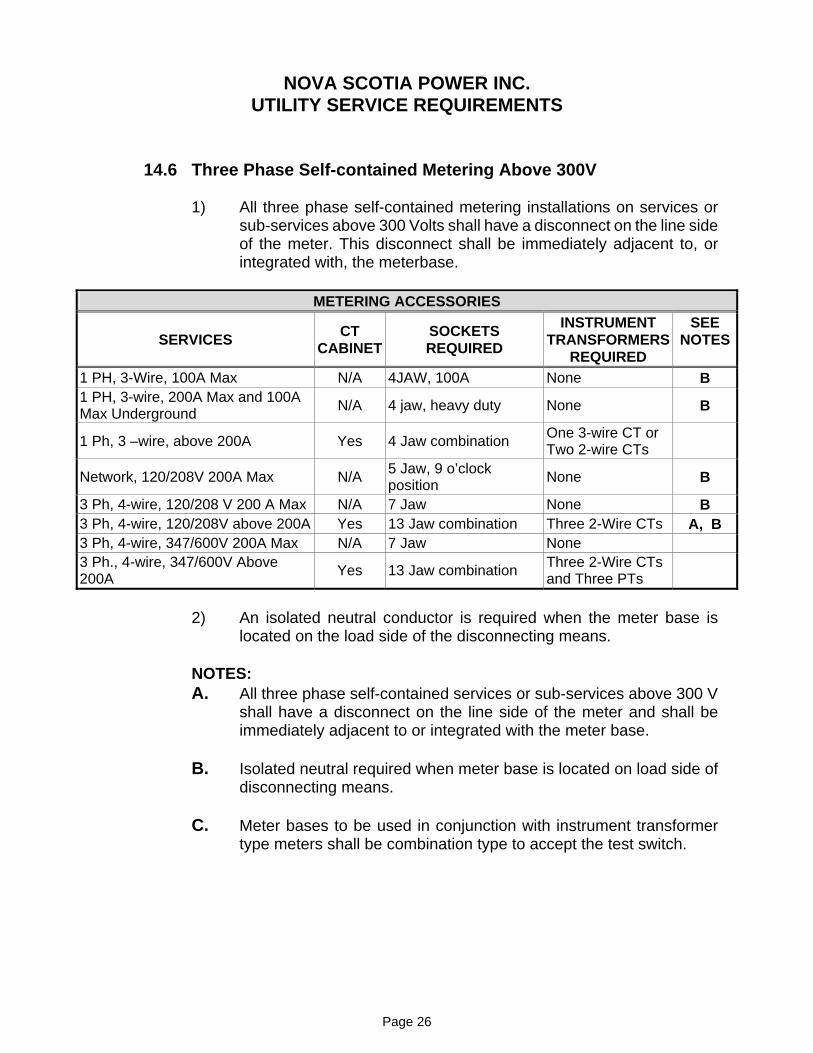
14.6 Three Phase Self-contained Metering Above 300V
1) All three phase self-contained metering installations on services or sub-services above 300 Volts shall have a disconnect on the line side of the meter. This disconnect shall be immediately adjacent to, or integrated with, the meterbase.
METERING ACCESSORIES
SERVICES CTCABINET
SOCKETSREQUIRED
INSTRUMENTTRANSFORMERS
REQUIRED
SEENOTES
1 PH, 3-Wire, 100A Max N/A 4JAW, 100A None B1 PH, 3-wire, 200A Max and 100A Max Underground N/A 4 jaw, heavy duty None B
1 Ph, 3 –wire, above 200A Yes 4 Jaw combination One 3-wire CT or Two 2-wire CTs
Network, 120/208V 200A Max N/A 5 Jaw, 9 o’clock position None B
3 Ph, 4-wire, 120/208 V 200 A Max N/A 7 Jaw None B3 Ph, 4-wire, 120/208V above 200A Yes 13 Jaw combination Three 2-Wire CTs A, B 3 Ph, 4-wire, 347/600V 200A Max N/A 7 Jaw None 3 Ph., 4-wire, 347/600V Above 200A Yes 13 Jaw combination Three 2-Wire CTs
and Three PTs
2) An isolated neutral conductor is required when the meter base is located on the load side of the disconnecting means.
NOTES:A. All three phase self-contained services or sub-services above 300 V
shall have a disconnect on the line side of the meter and shall be immediately adjacent to or integrated with the meter base.
B. Isolated neutral required when meter base is located on load side of disconnecting means.
C. Meter bases to be used in conjunction with instrument transformer type meters shall be combination type to accept the test switch.
NOVA SCOTIA POWER INC. UTILITY SERVICE REQUIREMENTS
Page 27
14.7 Primary Metering
NSPI Regulation 4.4 states the following: “Metering will normally be at the secondary side of the transformer. Should the customer’s requirements make it necessary for the Company to provide primary metering, then the customer will be required to make a capital contribution equal to the additional cost of the primary metering.”
The additional costs referred to in the regulation as quoted above include full equipment purchase and installation costs (unless otherwise noted) for the following;
a) primary metering equipment,
b) installation of any poles, platforms, foundations, or other supporting structures as required for the equipment,
c) changes and modifications to existing NSPI facilities as required to accommodate the primary metering,
d) removal of any facilities as required to accommodate the primary metering,
e) any other modifications or additions as required to accommodate the installation.
NOVA SCOTIA POWER INC. UTILITY SERVICE REQUIREMENTS
Page 28
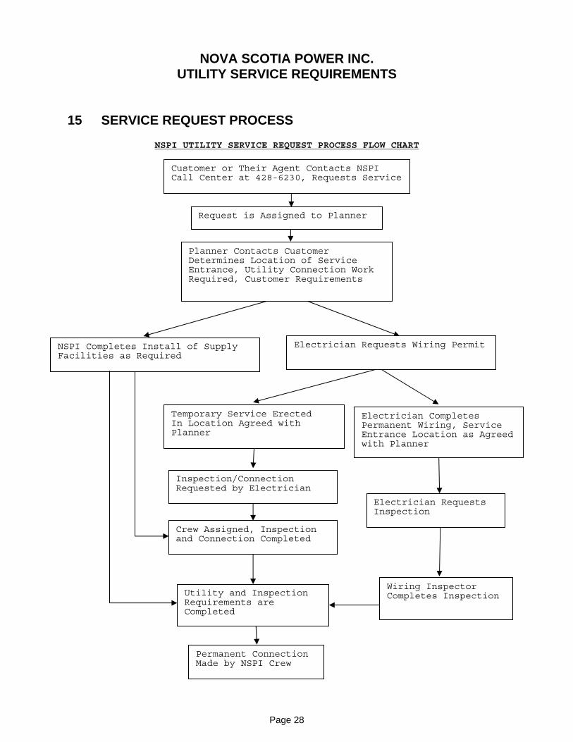
15 SERVICE REQUEST PROCESS
NSPI UTILITY SERVICE REQUEST PROCESS FLOW CHART
Customer or Their Agent Contacts NSPI Call Center at 428-6230, Requests Service
Request is Assigned to Planner
Planner Contacts Customer Determines Location of Service Entrance, Utility Connection Work Required, Customer Requirements
Electrician Requests Wiring Permit NSPI Completes Install of Supply Facilities as Required
Temporary Service Erected In Location Agreed with Planner
Crew Assigned, Inspection and Connection Completed
Electrician Completes Permanent Wiring, Service Entrance Location as Agreed with Planner
Wiring Inspector Completes Inspection
Permanent Connection Made by NSPI Crew
Utility and Inspection Requirements are Completed
Electrician Requests Inspection
Inspection/Connection Requested by Electrician
NOVA SCOTIA POWER INC. UTILITY SERVICE REQUIREMENTS
APPENDIX A SAFE CLEARANCES REPORT

NOVA SCOTIA POWER INC. UTILITY SERVICE REQUIREMENTS
Appendix A Page 1
NOVA SCOTIA POWER INC. UTILITY SERVICE REQUIREMENTS
Appendix A Page 2
NOVA SCOTIA POWER INC. UTILITY SERVICE REQUIREMENTS
APPENDIX B SERVICE ENTRANCE AND METERING
CONFIGURATIONS

NOVA SCOTIA POWER INC. UTILITY SERVICE REQUIREMENTS
NOVA SCOTIA POWER INC. UTILITY SERVICE REQUIREMENTS
NOVA SCOTIA POWER INC. UTILITY SERVICE REQUIREMENTS
NOVA SCOTIA POWER INC. UTILITY SERVICE REQUIREMENTS
NOVA SCOTIA POWER INC. UTILITY SERVICE REQUIREMENTS

NOVA SCOTIA POWER INC. UTILITY SERVICE REQUIREMENTS
APPENDIX C NSPI STANDARD DRAWINGS


NOVA SCOTIA POWER INC. UTILITY SERVICE REQUIREMENTS
APPENDIX D NSPI APPROVED CONNECTORS LISTING

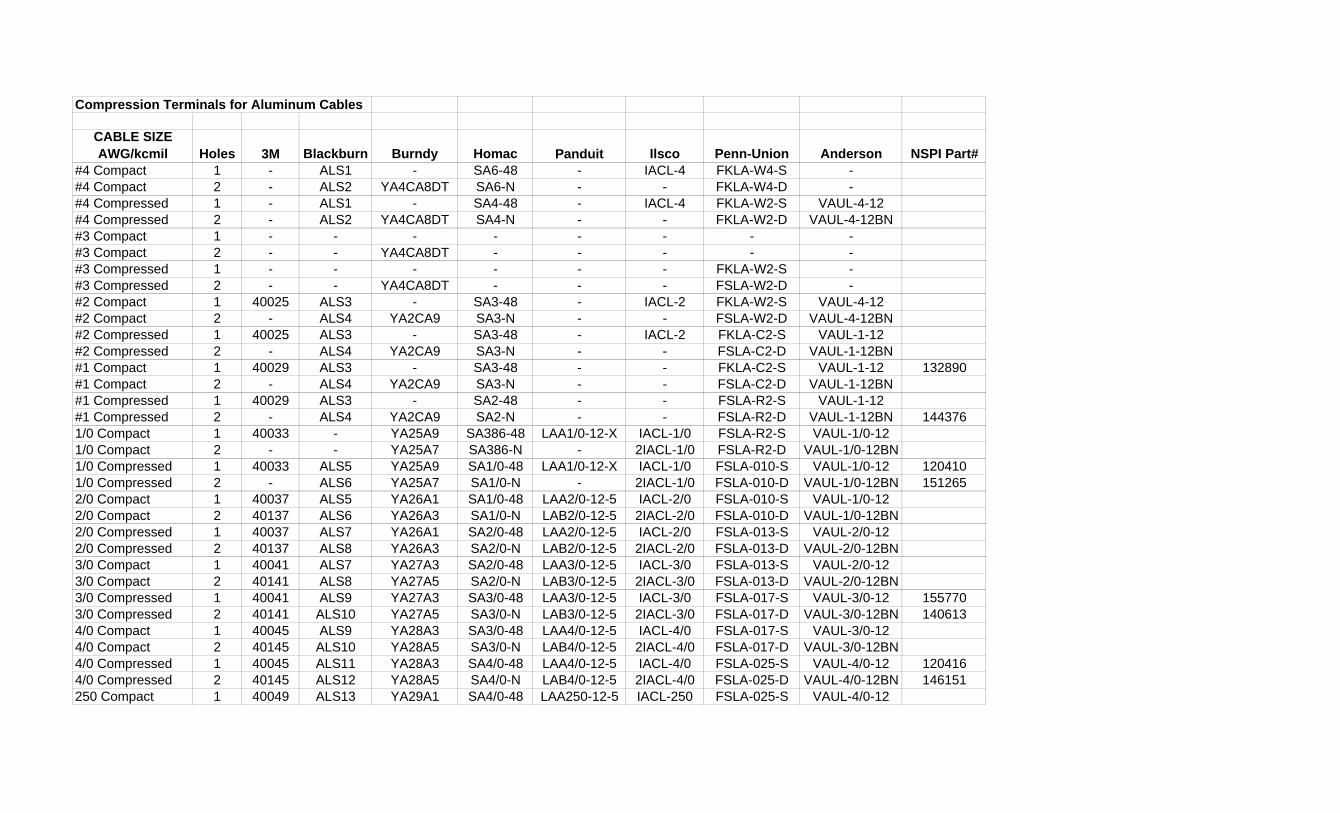
Compression Terminals for Aluminum Cables
CABLE SIZE AWG/kcmil Holes 3M Blackburn Burndy Homac Panduit Ilsco Penn-Union Anderson NSPI Part#
#4 Compact 1 - ALS1 - SA6-48 - IACL-4 FKLA-W4-S -#4 Compact 2 - ALS2 YA4CA8DT SA6-N - - FKLA-W4-D -#4 Compressed 1 - ALS1 - SA4-48 - IACL-4 FKLA-W2-S VAUL-4-12#4 Compressed 2 - ALS2 YA4CA8DT SA4-N - - FKLA-W2-D VAUL-4-12BN#3 Compact 1 - - - - - - - -#3 Compact 2 - - YA4CA8DT - - - - -#3 Compressed 1 - - - - - - FKLA-W2-S -#3 Compressed 2 - - YA4CA8DT - - - FSLA-W2-D -#2 Compact 1 40025 ALS3 - SA3-48 - IACL-2 FKLA-W2-S VAUL-4-12#2 Compact 2 - ALS4 YA2CA9 SA3-N - - FSLA-W2-D VAUL-4-12BN#2 Compressed 1 40025 ALS3 - SA3-48 - IACL-2 FKLA-C2-S VAUL-1-12#2 Compressed 2 - ALS4 YA2CA9 SA3-N - - FSLA-C2-D VAUL-1-12BN#1 Compact 1 40029 ALS3 - SA3-48 - - FKLA-C2-S VAUL-1-12 132890#1 Compact 2 - ALS4 YA2CA9 SA3-N - - FSLA-C2-D VAUL-1-12BN#1 Compressed 1 40029 ALS3 - SA2-48 - - FSLA-R2-S VAUL-1-12#1 Compressed 2 - ALS4 YA2CA9 SA2-N - - FSLA-R2-D VAUL-1-12BN 1443761/0 Compact 1 40033 - YA25A9 SA386-48 LAA1/0-12-X IACL-1/0 FSLA-R2-S VAUL-1/0-121/0 Compact 2 - - YA25A7 SA386-N - 2IACL-1/0 FSLA-R2-D VAUL-1/0-12BN1/0 Compressed 1 40033 ALS5 YA25A9 SA1/0-48 LAA1/0-12-X IACL-1/0 FSLA-010-S VAUL-1/0-12 1204101/0 Compressed 2 - ALS6 YA25A7 SA1/0-N - 2IACL-1/0 FSLA-010-D VAUL-1/0-12BN 1512652/0 Compact 1 40037 ALS5 YA26A1 SA1/0-48 LAA2/0-12-5 IACL-2/0 FSLA-010-S VAUL-1/0-122/0 Compact 2 40137 ALS6 YA26A3 SA1/0-N LAB2/0-12-5 2IACL-2/0 FSLA-010-D VAUL-1/0-12BN2/0 Compressed 1 40037 ALS7 YA26A1 SA2/0-48 LAA2/0-12-5 IACL-2/0 FSLA-013-S VAUL-2/0-122/0 Compressed 2 40137 ALS8 YA26A3 SA2/0-N LAB2/0-12-5 2IACL-2/0 FSLA-013-D VAUL-2/0-12BN3/0 Compact 1 40041 ALS7 YA27A3 SA2/0-48 LAA3/0-12-5 IACL-3/0 FSLA-013-S VAUL-2/0-123/0 Compact 2 40141 ALS8 YA27A5 SA2/0-N LAB3/0-12-5 2IACL-3/0 FSLA-013-D VAUL-2/0-12BN3/0 Compressed 1 40041 ALS9 YA27A3 SA3/0-48 LAA3/0-12-5 IACL-3/0 FSLA-017-S VAUL-3/0-12 1557703/0 Compressed 2 40141 ALS10 YA27A5 SA3/0-N LAB3/0-12-5 2IACL-3/0 FSLA-017-D VAUL-3/0-12BN 1406134/0 Compact 1 40045 ALS9 YA28A3 SA3/0-48 LAA4/0-12-5 IACL-4/0 FSLA-017-S VAUL-3/0-124/0 Compact 2 40145 ALS10 YA28A5 SA3/0-N LAB4/0-12-5 2IACL-4/0 FSLA-017-D VAUL-3/0-12BN4/0 Compressed 1 40045 ALS11 YA28A3 SA4/0-48 LAA4/0-12-5 IACL-4/0 FSLA-025-S VAUL-4/0-12 1204164/0 Compressed 2 40145 ALS12 YA28A5 SA4/0-N LAB4/0-12-5 2IACL-4/0 FSLA-025-D VAUL-4/0-12BN 146151250 Compact 1 40049 ALS13 YA29A1 SA4/0-48 LAA250-12-5 IACL-250 FSLA-025-S VAUL-4/0-12
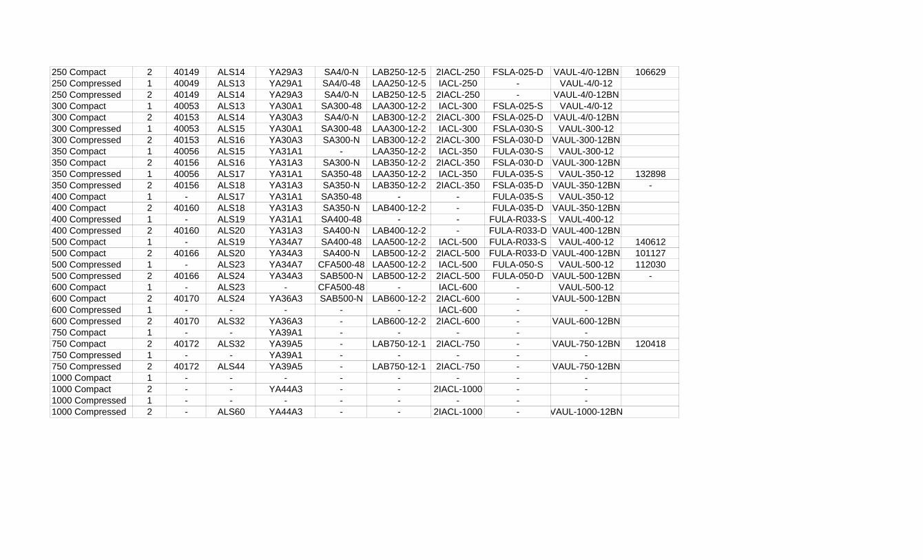
250 Compact 2 40149 ALS14 YA29A3 SA4/0-N LAB250-12-5 2IACL-250 FSLA-025-D VAUL-4/0-12BN 106629250 Compressed 1 40049 ALS13 YA29A1 SA4/0-48 LAA250-12-5 IACL-250 - VAUL-4/0-12250 Compressed 2 40149 ALS14 YA29A3 SA4/0-N LAB250-12-5 2IACL-250 - VAUL-4/0-12BN300 Compact 1 40053 ALS13 YA30A1 SA300-48 LAA300-12-2 IACL-300 FSLA-025-S VAUL-4/0-12300 Compact 2 40153 ALS14 YA30A3 SA4/0-N LAB300-12-2 2IACL-300 FSLA-025-D VAUL-4/0-12BN300 Compressed 1 40053 ALS15 YA30A1 SA300-48 LAA300-12-2 IACL-300 FSLA-030-S VAUL-300-12300 Compressed 2 40153 ALS16 YA30A3 SA300-N LAB300-12-2 2IACL-300 FSLA-030-D VAUL-300-12BN350 Compact 1 40056 ALS15 YA31A1 - LAA350-12-2 IACL-350 FULA-030-S VAUL-300-12350 Compact 2 40156 ALS16 YA31A3 SA300-N LAB350-12-2 2IACL-350 FSLA-030-D VAUL-300-12BN350 Compressed 1 40056 ALS17 YA31A1 SA350-48 LAA350-12-2 IACL-350 FULA-035-S VAUL-350-12 132898350 Compressed 2 40156 ALS18 YA31A3 SA350-N LAB350-12-2 2IACL-350 FSLA-035-D VAUL-350-12BN -400 Compact 1 - ALS17 YA31A1 SA350-48 - - FULA-035-S VAUL-350-12400 Compact 2 40160 ALS18 YA31A3 SA350-N LAB400-12-2 - FULA-035-D VAUL-350-12BN400 Compressed 1 - ALS19 YA31A1 SA400-48 - - FULA-R033-S VAUL-400-12400 Compressed 2 40160 ALS20 YA31A3 SA400-N LAB400-12-2 - FULA-R033-D VAUL-400-12BN500 Compact 1 - ALS19 YA34A7 SA400-48 LAA500-12-2 IACL-500 FULA-R033-S VAUL-400-12 140612500 Compact 2 40166 ALS20 YA34A3 SA400-N LAB500-12-2 2IACL-500 FULA-R033-D VAUL-400-12BN 101127500 Compressed 1 - ALS23 YA34A7 CFA500-48 LAA500-12-2 IACL-500 FULA-050-S VAUL-500-12 112030500 Compressed 2 40166 ALS24 YA34A3 SAB500-N LAB500-12-2 2IACL-500 FULA-050-D VAUL-500-12BN -600 Compact 1 - ALS23 - CFA500-48 - IACL-600 - VAUL-500-12600 Compact 2 40170 ALS24 YA36A3 SAB500-N LAB600-12-2 2IACL-600 - VAUL-500-12BN600 Compressed 1 - - - - - IACL-600 - -600 Compressed 2 40170 ALS32 YA36A3 - LAB600-12-2 2IACL-600 - VAUL-600-12BN750 Compact 1 - - YA39A1 - - - - -750 Compact 2 40172 ALS32 YA39A5 - LAB750-12-1 2IACL-750 - VAUL-750-12BN 120418750 Compressed 1 - - YA39A1 - - - - -750 Compressed 2 40172 ALS44 YA39A5 - LAB750-12-1 2IACL-750 - VAUL-750-12BN1000 Compact 1 - - - - - - - -1000 Compact 2 - - YA44A3 - - 2IACL-1000 - -1000 Compressed 1 - - - - - - - -1000 Compressed 2 - ALS60 YA44A3 - - 2IACL-1000 - VAUL-1000-12BN
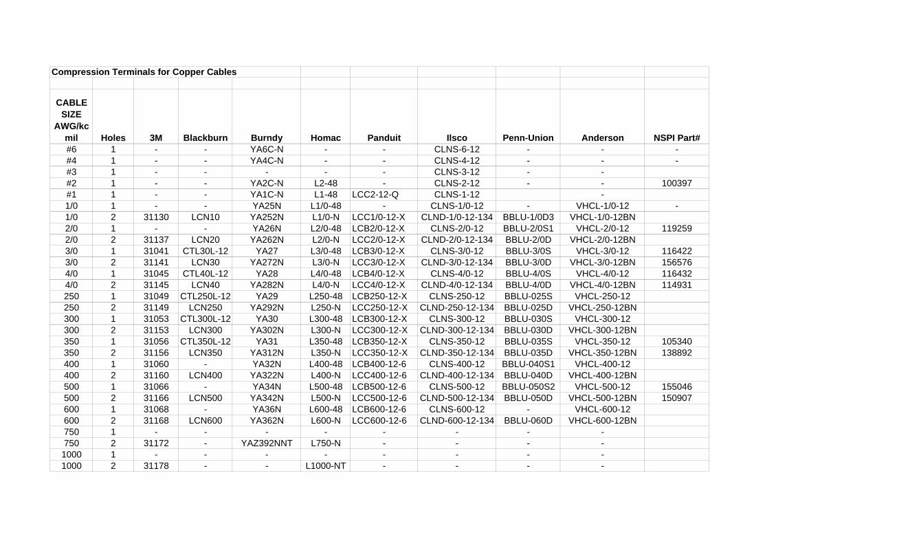
Compression Terminals for Copper Cables
CABLE SIZE
AWG/kcmil Holes 3M Blackburn Burndy Homac Panduit Ilsco Penn-Union Anderson NSPI Part##6 1 - - YA6C-N - - CLNS-6-12 - - -#4 1 - - YA4C-N - - CLNS-4-12 - - -#3 1 - - - - - CLNS-3-12 - -#2 1 - - YA2C-N L2-48 - CLNS-2-12 - - 100397#1 1 - - YA1C-N L1-48 LCC2-12-Q CLNS-1-12 -1/0 1 - - YA25N L1/0-48 - CLNS-1/0-12 - VHCL-1/0-12 -1/0 2 31130 LCN10 YA252N L1/0-N LCC1/0-12-X CLND-1/0-12-134 BBLU-1/0D3 VHCL-1/0-12BN2/0 1 - - YA26N L2/0-48 LCB2/0-12-X CLNS-2/0-12 BBLU-2/0S1 VHCL-2/0-12 1192592/0 2 31137 LCN20 YA262N L2/0-N LCC2/0-12-X CLND-2/0-12-134 BBLU-2/0D VHCL-2/0-12BN3/0 1 31041 CTL30L-12 YA27 L3/0-48 LCB3/0-12-X CLNS-3/0-12 BBLU-3/0S VHCL-3/0-12 1164223/0 2 31141 LCN30 YA272N L3/0-N LCC3/0-12-X CLND-3/0-12-134 BBLU-3/0D VHCL-3/0-12BN 1565764/0 1 31045 CTL40L-12 YA28 L4/0-48 LCB4/0-12-X CLNS-4/0-12 BBLU-4/0S VHCL-4/0-12 1164324/0 2 31145 LCN40 YA282N L4/0-N LCC4/0-12-X CLND-4/0-12-134 BBLU-4/0D VHCL-4/0-12BN 114931250 1 31049 CTL250L-12 YA29 L250-48 LCB250-12-X CLNS-250-12 BBLU-025S VHCL-250-12250 2 31149 LCN250 YA292N L250-N LCC250-12-X CLND-250-12-134 BBLU-025D VHCL-250-12BN300 1 31053 CTL300L-12 YA30 L300-48 LCB300-12-X CLNS-300-12 BBLU-030S VHCL-300-12300 2 31153 LCN300 YA302N L300-N LCC300-12-X CLND-300-12-134 BBLU-030D VHCL-300-12BN350 1 31056 CTL350L-12 YA31 L350-48 LCB350-12-X CLNS-350-12 BBLU-035S VHCL-350-12 105340350 2 31156 LCN350 YA312N L350-N LCC350-12-X CLND-350-12-134 BBLU-035D VHCL-350-12BN 138892400 1 31060 - YA32N L400-48 LCB400-12-6 CLNS-400-12 BBLU-040S1 VHCL-400-12400 2 31160 LCN400 YA322N L400-N LCC400-12-6 CLND-400-12-134 BBLU-040D VHCL-400-12BN500 1 31066 - YA34N L500-48 LCB500-12-6 CLNS-500-12 BBLU-050S2 VHCL-500-12 155046500 2 31166 LCN500 YA342N L500-N LCC500-12-6 CLND-500-12-134 BBLU-050D VHCL-500-12BN 150907600 1 31068 - YA36N L600-48 LCB600-12-6 CLNS-600-12 - VHCL-600-12600 2 31168 LCN600 YA362N L600-N LCC600-12-6 CLND-600-12-134 BBLU-060D VHCL-600-12BN750 1 - - - - - - - -750 2 31172 - YAZ392NNT L750-N - - - -1000 1 - - - - - - - -1000 2 31178 - - L1000-NT - - - -

NOVA SCOTIA POWER INC. UTILITY SERVICE REQUIREMENTS
APPENDIX E NSPI APPROVED UNDERGROUND MATERIALS

NOVA SCOTIA POWER INC. UTILITY SERVICE REQUIREMENTS
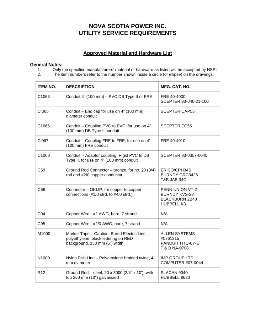
Approved Material and Hardware List
General Notes: 1. Only the specified manufacturers’ material or hardware as listed will be accepted by NSPI. 2. The item numbers refer to the number shown inside a circle (or ellipse) on the drawings.
ITEM NO. DESCRIPTION MFG. CAT. NO.
C1063 Conduit 4” (100 mm) – PVC DB Type II or FRE FRE 40-4000 SCEPTER 83-040-21-100
CI065 Conduit – End cap for use on 4” (100 mm) diameter conduit
SCEPTER CAP55
C1066 Conduit – Coupling PVC to PVC, for use on 4” (100 mm) DB Type II conduit
SCEPTER EC55
Cl067 Conduit – Coupling FRE to FRE, for use on 4” (100 mm) FRE conduit
FRE 40-4010
C1068 Conduit - Adaptor coupling, Rigid PVC to DB Type II, for use on 4” (100 mm) conduit
SCEPTER 83-0357-0040
C59 Ground Rod Connector – bronze, for no. 20 (3/4) rod and #2/0 copper conductor
ERICO/CPH34SBURNDY GRC3426 T&B JAB 34C
C68 Connector – OKLIP, for copper to copper connections (#1/0 strd. to #4/0 strd.)
PENN UNION VT-2 BURNDY KVS-28 BLACKBURN 2B40 HUBBELL K3
C94 Copper Wire - #2 AWG, bare, 7 strand N/A
C95 Copper Wire - #2/0 AWG, bare, 7 strand N/A
M1000 Marker Tape – Caution, Bured Electric Line – polyethylene, black lettering on RED background, 150 mm (6”) width
ALLEN SYSTEMS #0761315PANDUIT HTU-6Y-E T & B NA-0708
N1000 Nylon Fish Line – Polyethylene braided twine, 4 mm diameter
IMP GROUP LTD. COMPUTER #07-0044
R12 Ground Rod – steel, 20 x 3000 (3/4” x 10’), with top 250 mm (10”) galvanized
SLACAN 9340 HUBBELL 8620