Embed Size (px)
Citation preview

UTILITY OF OPTICAL COHERENCE TOMOGRAPHY IMAGING WITH ANGIOGRAPHIC CO-REGISTRATION FOR THE GUIDANCE OF PERCUTANEOUS CORONARY INTERVENTION Antonios Karanasos, MD, PhD, Jors N. van der Sijde, MD Jurgen Ligthart, Karen Witberg, Evelyn Regar
Department of Interventional Cardiology, Thoraxcenter Erasmus University Medical Center, Rotterdam, Netherlands

2 | ILUMIEN™ OPTIS™ PCI Optimization and OPTIS™ Integrated Systems

ILUMIEN™ OPTIS™ PCI Optimization and OPTIS™ Integrated Systems | 3
UTILITY OF OPTICAL COHERENCE TOMOGRAPHY IMAGING WITH ANGIOGRAPHIC CO-REGISTRATION FOR THE GUIDANCE OF PERCUTANEOUS CORONARY INTERVENTION INTRODUCTIONIntracoronary optical coherence tomography (OCT) is a light-based imaging modality able to visualize with high resolution (~10 μm) the vascular morphology and the acute and chronic effects of intervention with intracoronary devices.1,2 OCT could therefore find application in the guidance of percutaneous coronary intervention (PCI), allowing a thorough preprocedural lesion assessment, which enables accurate device sizing, selection of the vessel segment requiring treatment, and thus, efficient planning of the implantation strategy (Table 1).3 Moreover, it can be used for the assessment of the acute procedural result, allowing the estimation of stent expansion and vessel injury. Consequently, intravascular imaging can in this way assist in the optimization of the acute implantation result, the significance of which is underscored by observations of an association between suboptimal implantation and stent failure.4 Importantly, several studies and metaanalyses have shown that the use of imaging guidance might improve outcome.5-7
Although OCT can provide a high amount of detail in the assessment of coronary arteries, this information might be challenging to be directly applied in the guidance of interventions in the daily cath lab practice, which are performed using real-time fluoroscopic guidance. This could happen because the spatial correspondence of OCT findings with the vessel angiogram is not always straightforward as a result of vessel overlap, foreshortening or the inability to visualize a complex three-dimensional structure correctly in a two-dimensional image. As the operator is using the angiographic image as a guide for performing the intervention, it is essential for him or her to ensure correct spatial orientation of the invasive imaging findings with the angiogram. Such problems might become more exaggerated in cases with diffuse disease, angiographically silent lesions, or in the absence of side branches that can function as landmarks. In order to overcome this problem, approaches implementing an online co-registration of OCT with the coronary angiogram, which allows the operator to scroll through a synchronized dataset, would be highly desired. Such information could be useful for procedural planning and longitudinal assessment of atherosclerotic lesions.
We present a new technology allowing the online co-registration of OCT images with the angiogram in the catheterization laboratory and discuss its potential utility in optimizing procedural outcome in everyday practice.
Table 1. Potential Clinical Applications of OCT3
Setting Application
Lesion evaluation
Assessment of culprit lesion in acute coronary syndromes: evaluation for plaque rupture and/or thrombus in patients without angiographically evident culprit lesion
Evaluation of lesions with angiographic haziness: differential diagnosis between thrombus, dissection, heavy calcification
Determination about presence or absence of plaque (e.g., in coronary spasm)
Preprocedural assessment
Luminal measurements for selection of balloon and stent dimensions
Assessment of plaque morphology in order to guide therapeutic strategy and device selection (rotablation, cutting balloon, etc.)
Evaluation of the optimal location in the vessel for implantation of a coronary stent
Use for tracking the exact guidewire position (i.e., in chronic total occlusion or in bifurcation stenting)
Use in bifurcation intervention (assessment of carina, ostia of side branches, stent cell geometry)
Postprocedural assessment
Assessment of stent expansion (detection of underexpansion, residual stenosis, incomplete stent apposition)
Assessment of vascular injury: detection of edge dissections, tissue protrusion, intra-stent thrombus
Assessment of intervention by adjunctive devices: measurement of luminal enlargement after cutting balloon angioplasty, assessment of the reduction of calcification after rotablation
Assessment of adjunctive therapies in acute coronary syndromes: evaluation of residual thrombus burden after thrombectomy or selective administration of IIb/IIIa antagonists
Follow-up stent assessment
Mid-term and long-term assessment of stent safety and efficacy: evaluation of stent restenosis (quantitative and qualitative), stent thrombosis, and stent coverage as a surrogate for vessel healing
Monitoring of the bioresorption and the healing response after implantation of bioresorbable scaffolds

4 | ILUMIEN™ OPTIS™ PCI Optimization and OPTIS™ Integrated Systems
OPTIS™ INTEGRATED SYSTEM: A NEW OCT IMAGING SYSTEM WITH ONLINE ANGIOGRAPHIC CO-REGISTRATIONThe OPTIS™ integrated system St. Jude Medical, St Paul, MN, US is an OCT imaging system that is integrated in the catheterization laboratory and has the additional ability to provide a real-time co-registration of OCT images with the angiogram of the studied vessel. The OPTIS integrated system can be directly installed in a catheterization laboratory and consists of the OCT imaging system, a pullback device, monitors and a tableside controller, while image acquisition is being performed with the Dragonfly™ Duo St. Jude Medical OCT imaging catheter.
The imaging system is located within the control room of the catheterization laboratory, while OCT data are projected in real time on a screen within the intervention room. Angiographic data from the existing angiographic system are retrieved and displayed simultaneously on the same screen. The pullback device is stowed in a holster positioned at the cath lab table. Direct tableside controls at the cath lab table allow for an autonomous handling of the system by the operating physician without the need for extra cable connections as in systems based on mobile carts. The OCT system specifications are similar to the previously used ILUMIEN™ OPTIS™ PCI Optimization system St. Jude Medical allowing for acquisition of OCT images with a frame rate of 180 frames per second. The pullback speed can be adjusted by the operator in one of two settings:
1. A Survey mode with a 75 mm long pullback and a frame density of 5 frames per mm, which finds application in the assessment of longer coronary segments; and
2. A High Resolution mode with a 54 mm long pullback and a frame density of 10 frames per mm, which can provide a more detailed longitudinal assessment of the vessel and stent morphology.
The Dragonfly Duo imaging catheter is a 2.7 F, rapid exchange monorail catheter with a pullback speed up to 75 mm/sec. Further, the distal catheter end carries a number of markers: a distal radiopaque marker indicating the guidewire exit, a proximal marker that indicates the ending position of the pullback and a marker indicating
the position of the OCT lens. This marker moves simultaneously with the lens and allows the real-time tracking of its position by fluoroscopy. Finally, a femoral shaft guide marker has been added to identify when the Dragonfly Duo catheter is exiting a 100 cm guide catheter.
A number of different options for displaying the OCT information are available. These include an automated lumen profile, which is generated after automated lumen detection in all OCT cross-sectional images throughout the pullback. This view provides information regarding the mean luminal diameter along the pullback, thus enabling a luminographic assessment of the studied vessel, but with the use of OCT measurements, overcoming potential limitations of angiography in luminal assessment such as foreshortening, vessel overlap or filling artifacts.
Information such as minimal lumen diameter, reference diameters and degree of area or diameter stenosis are simultaneously projected on the screen, thus providing a fast and practical assessment of the severity of luminal stenosis, while giving important information for sizing. Moreover, OCT information is also reconstructed in 3-D and can be displayed in parallel. This visualization might aid in the assessment of bifurcations or in cases with stent deformation.
The angiographic image that is recorded during the pullback is projected together with the OCT image. After semi-automatic co-registration, a small white marker is projected over the angiogram, indicating the exact location of the displayed OCT frame on the angiogram. This information is useful for the direct utilization of intravascular imaging findings in procedural decision making, as the location of the OCT images is directly displayed and facilitates the selection of a suitable landing zone for the intervention.
CLINICAL RELEVANCE OF ONLINE OCT CO-REGISTRATIONOverall, the use of a system able to provide online spatial co-registration of the high-resolution intravascular imaging findings with the angiographic image could improve decision making in the cath lab. This integration
ILUMIEN™ OPTIS™ PCI Optimization and OPTIS™ Integrated Systems | 5
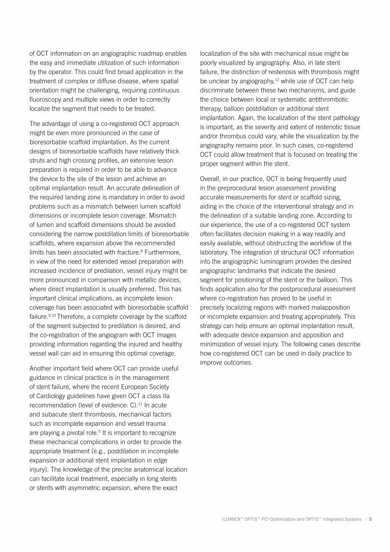
of OCT information on an angiographic roadmap enables the easy and immediate utilization of such information by the operator. This could find broad application in the treatment of complex or diffuse disease, where spatial orientation might be challenging, requiring continuous fluoroscopy and multiple views in order to correctly localize the segment that needs to be treated.
The advantage of using a co-registered OCT approach might be even more pronounced in the case of bioresorbable scaffold implantation. As the current designs of bioresorbable scaffolds have relatively thick struts and high crossing profiles, an extensive lesion preparation is required in order to be able to advance the device to the site of the lesion and achieve an optimal implantation result. An accurate delineation of the required landing zone is mandatory in order to avoid problems such as a mismatch between lumen scaffold dimensions or incomplete lesion coverage. Mismatch of lumen and scaffold dimensions should be avoided considering the narrow postdilation limits of bioresorbable scaffolds, where expansion above the recommended limits has been associated with fracture.8 Furthermore, in view of the need for extended vessel preparation with increased incidence of predilation, vessel injury might be more pronounced in comparison with metallic devices, where direct implantation is usually preferred. This has important clinical implications, as incomplete lesion coverage has been associated with bioresorbable scaffold failure.9,10 Therefore, a complete coverage by the scaffold of the segment subjected to predilation is desired, and the co-registration of the angiogram with OCT images providing information regarding the injured and healthy vessel wall can aid in ensuring this optimal coverage.
Another important field where OCT can provide useful guidance in clinical practice is in the management of stent failure, where the recent European Society of Cardiology guidelines have given OCT a class IIa recommendation (level of evidence: C).11 In acute and subacute stent thrombosis, mechanical factors such as incomplete expansion and vessel trauma are playing a pivotal role.5 It is important to recognize these mechanical complications in order to provide the appropriate treatment (e.g., postdilation in incomplete expansion or additional stent implantation in edge injury). The knowledge of the precise anatomical location can facilitate local treatment, especially in long stents or stents with asymmetric expansion, where the exact
localization of the site with mechanical issue might be poorly visualized by angiography. Also, in late stent failure, the distinction of restenosis with thrombosis might be unclear by angiography,12 while use of OCT can help discriminate between these two mechanisms, and guide the choice between local or systematic antithrombotic therapy, balloon postdilation or additional stent implantation. Again, the localization of the stent pathology is important, as the severity and extent of restenotic tissue and/or thrombus could vary, while the visualization by the angiography remains poor. In such cases, co-registered OCT could allow treatment that is focused on treating the proper segment within the stent.
Overall, in our practice, OCT is being frequently used in the preprocedural lesion assessment providing accurate measurements for stent or scaffold sizing, aiding in the choice of the interventional strategy and in the delineation of a suitable landing zone. According to our experience, the use of a co-registered OCT system often facilitates decision making in a way readily and easily available, without obstructing the workflow of the laboratory. The integration of structural OCT information into the angiographic luminogram provides the desired angiographic landmarks that indicate the desired segment for positioning of the stent or the balloon. This finds application also for the postprocedural assessment where co-registration has proved to be useful in precisely localizing regions with marked malapposition or incomplete expansion and treating appropriately. This strategy can help ensure an optimal implantation result, with adequate device expansion and apposition and minimization of vessel injury. The following cases describe how co-registered OCT can be used in daily practice to improve outcomes.

6 | ILUMIEN™ OPTIS™ PCI Optimization and OPTIS™ Integrated Systems
Figure 1.
Figure 2. OCT images before scaffold implantation.CASE STUDY 1. OCT-GUIDED BVS IMPLANTATION IN A PATIENT WITH ACUTE CORONARY SYNDROMEA 46-year-old male without cardiovascular history underwent coronary catheterization for non-ST elevated myocardial infarction. Angiogram showed a sub-occlusive lesion in the marginal branch that was considered the culprit (Figure 1), with an online measured interpolated
reference diameter of 2.33 mm by QCA, while the lesion length was 18 mm.
After predilation with a 2.5 x 15mm balloon, an OCT pullback co-registered with the angiogram was acquired in order to assess the lesion, select device size and determine the landing zone. Cross-sectional OCT images (Figure 2) revealed an occlusive lesion at the minimal lumen area. At the angiographically suggested proximal reference segment, OCT revealed the presence of a thin-cap fibroatheroma with mural thrombus. Therefore, another more proximal landing zone was selected based on the OCT images, with a mean diameter of 3.86 mm and a maximum diameter of 3.93 mm. As the maximum diameter in the proximal landing zone was
below 4 mm, we selected a 3.5 mm Absorb™ (Abbott Vascular, Santa Clara, CA, US) bioresorbable scaffold that can be safely expanded up to a 4 mm diameter. Also, seeing the high-risk plaque morphology at the angiography suggested landing zone, a 23 mm long scaffold was selected instead of the 18 mm suggested by angiography for complete coverage of the diseased segment. Furthermore, we decided upfront that postdilatation would be necessary in order to match the proximal reference diameter. A 3.5 x 23 mm scaffold was then implanted with low-pressure inflation in order to avoid vessel injury due to the tapering of the vessel distally.
Pre-interventional angiogram of the marginal branch with online quan-titative coronary angiography (QCA) measurements after intracoronary nitrate administration. Online QCA suggested a lesion length of 18 mm, with a proximal reference diameter of 3.34 mm and an interpolated reference diameter of 2.33 mm.
A. Minimal lumen area site at the obtuse marginal branch, in which the OCT catheter becomes occlusive. B. Site of angiographically suggested proximal landing zone. In OCT a thin-cap fibroatheroma with abundant necrotic core (*) is present with some mural thrombus (arrow). C. OCT suggested proximal landing zone. A normal three-lay-ered appearance is observed with an average diameter of 3.86 mm, which was selected as the proximal landing zone. Based the imaging findings, a minimum length of 21.5 mm was required for complete coverage of the diseased segment.

ILUMIEN™ OPTIS™ PCI Optimization and OPTIS™ Integrated Systems | 7
Immediately after implantation, a proximal postdilation was performed with a 3.75 x 15 mm noncompliant balloon (Figure 3). A final OCT was performed to assess the implantation result, showing a good scaffold expansion with small-scale malapposition (less than one strut thickness) proximally that was accepted, and absence of vessel injury at the edges of the stent (Figure 4).
Overall, in this case OCT helped us to achieve optimal lesion coverage, select the size and length of the implanted scaffold that was different from what was suggested by online QCA and guide the use of proximal postdilation. Moreover, OCT helped confirm the absence of distal vessel injury and a good expansion and apposition.
CASE STUDY 2. IDENTIFICATION OF
Figure 3. Scaffold implantation and postdilation.
Figure 4. Postinterventional OCT images.
The location of the marker on the OCT catheter was used to guide scaffold implantation (A. and B.) with low-inflation pressure. Due to the tapering of the vessel, a postdilation was performed proximally immediately after scaffold implantation (C.) resulting in a good angiographic result (D.).
A. OCT image at the location of the proximal scaffold marker (white arrow) showing good expansion and small-scale malapposition (less than one strut thickness; yellow arrow). The mean lumen diameter is 3.80 mm. B. The distal edge shows a normal vessel morphology without any edge dissection.
8 | ILUMIEN™ OPTIS™ PCI Optimization and OPTIS™ Integrated Systems
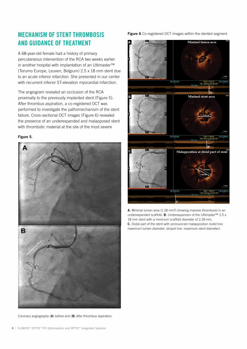
MECHANISM OF STENT THROMBOSIS AND GUIDANCE OF TREATMENTA 68-year-old female had a history of primary percutaneous intervention of the RCA two weeks earlier in another hospital with implantation of an Ultimaster™ (Terumo Europe, Leuven, Belgium) 2.5 x 18 mm stent due to an acute inferior infarction. She presented in our center with recurrent inferior ST-elevation myocardial infarction.
The angiogram revealed an occlusion of the RCA proximally to the previously implanted stent (Figure 5). After thrombus aspiration, a co-registered OCT was performed to investigate the pathomechanism of the stent failure. Cross-sectional OCT images (Figure 6) revealed the presence of an underexpanded and malapposed stent with thrombotic material at the site of the most severe
Figure 5.
Figure 6 Co-registered OCT images within the stented segment.
Coronary angiography (A) before and (B) after thrombus aspiration.
A. Minimal lumen area (1.18 mm²) showing massive thrombosis in an underexpanded scaffold. B. Underexpansion of the Ultimaster™ 2.5 x 18 mm stent with a minimum scaffold diameter of 2.18 mm, C. Distal part of the stent with pronounced malapposition (solid line: maximum lumen diameter, striped line: maximum stent diameter).

ILUMIEN™ OPTIS™ PCI Optimization and OPTIS™ Integrated Systems | 9
underexpansion.
Moreover, OCT showed the presence of extensive disease distally to the stent comprised of several stenotic lesions (Figure 7).
Importantly, these findings of excessive malapposition, underexpansion and in-stent stenosis due to thrombus were not visible by angiography, while the severity of the downstream disease was also underestimated. A landing zone was selected based on the lumen profile view, aiming to cover the entire diseased segment. OCT measurements dictated the selection of a Promus™ 3.0 x 32 mm (Boston Scientific, Natick, MA, US), with the intention to distal overlap the pre-existing stent. Immediately postimplantation, after considering the lumen area at the site of the malapposition (2.67 mm) and a distal reference area of 2.82 mm, the balloon of the stent (3.0 mm diameter) was used for postdilation of the entire stented region, including the underexpanded and malapposed Ultimaster stent. This resulted in a well-expanded stent, landing in a relatively healthy segment and with a short segment of strut overlap (Figure 8). The lumen area within the previous stent was also improved (MLA increased from 1.18 mm² to 5.29 mm²), as were apposition and expansion of this stent.
In this case, OCT helped us understand the pathomechanism of stent thrombosis and also revealed the presence of severe under-recognized atherosclerotic disease distally to the stent. The visualization of the substrate together with the accurate measurements helped us selected the proper treatment, resulting in optimal lesion coverage and correction of the mechanical issues of the thrombosed stent.
CONCLUSIONSOCT is an intravascular imaging modality with the
Figure 7. Co-registered OCT images downstream of the stented segment demonstrating extensive disease.
Diffuse disease distally to the previously stented segment. A. and B. demonstrate sites with luminal narrowing with the most distal (B.) located about 25 mm distally to the previously implanted stent. C. demonstrates the distal landing zone selected at approximately 30 mm distal of the underexpanded stent to entirely cover the diseased segment.

10 | ILUMIEN™ OPTIS™ PCI Optimization and OPTIS™ Integrated Systems
Figure 8. Postinterventional co-registered OCT images. potential to play an integral role in the daily cath lab routine. Information acquired by OCT is crucial in preprocedural planning, while OCT can be used to assess acute postprocedural result, guiding the performance or deferral of further intervention. Recently introduced technological developments providing a spatial co-registration of the OCT findings with the angiographic image can enable the operator to use this information for procedural guidance in an easy, quick and reliable manner. The adaptation of such imaging-guided strategies can aid decision making in the everyday practice while helping the optimization of the procedural result.
OCT image showing a relatively healthy distal edge (A). At the site of the overlap, which is approximately 1.8 mm long (B), the stents are well expanded and apposed to the vessel wall, thus correcting the baseline malapposition at this site. Expansion of the proximal segment (C) has also greatly been improved after postdilation with a lumen diameter of 2.97 mm.

ILUMIEN™ OPTIS™ PCI Optimization and OPTIS™ Integrated Systems | 11
REFERENCES1. Tearney, G. J., Regar, E., Akasaka, T., Adriaenssens, T., Barlis, P.,
Bezerra, H. G., … International Working Group for Intravascular
Optical Coherence Tomography (IWG-IVOCT). (2012). Consensus
standards for acquisition, measurement, and reporting of
intravascular optical coherence tomography studies: A report from
the International Working Group for Intravascular Optical Coherence
Tomography Standardization and Validation. Journal of the American
College of Cardiology, 59, 1058-1072.
2. Prati, F., Guagliumi, G., Mintz, G. S., Costa, M., Regar, E.,
Akasaka, T., . . . Di Mario, C. (2012). Expert review document
part 2: methodology, terminology and clinical applications of
optical coherence tomography for the assessment of interventional
procedures. European Heart Journal, 33, 2513-2520.
3. Karanasos, A., Ligthart, J., Witberg, K., van Soest, G., Bruining, N.,
& Regar, E. (2012). Optical coherence tomography: potential clinical
applications. Current Cardiovascular Imaging Reports, 5, 206-220.
4. Choi, S. Y., Witzenbichler, B., Maehara, A., Lansky, A. J., Guagliumi,
G., Brodie, B., . . . Stone, G. W. (2011). Intravascular ultrasound
findings of early stent thrombosis after primary percutaneous
intervention in acute myocardial infarction: a Harmonizing
Outcomes with Revascularization and Stents in Acute Myocardial
Infarction (HORIZONS-AMI) substudy. Circulation: Cardiovascular
Interventions, 4, 239-47.
5. Witzenbichler, B., Maehara, A., Weisz, G., Neumann, F. J., Rinaldi,
M. J., Metzger, D. C., . . . Stone, G. W. (2014). Relationship between
intravascular ultrasound guidance and clinical outcomes after drug-
eluting stents: the assessment of dual antiplatelet therapy with drug-
eluting stents (ADAPT-DES) study. Circulation, 129, 463-470.
6. Prati, F., Di Vito, L., Biondi-Zoccai, G., Occhipinti, M., La Manna, A.,
Tamburino, C., … Albertucci, M. (2012). Angiography alone versus
angiography plus optical coherence tomography to guide decision-
making during percutaneous coronary intervention: The Centro
per la Lotta contro I’Infarto-Optimisation of Percutaneous Coronary
Intervention (CLI-OPCI) study. EuroIntervention, 8, 823-829.
7. Zhang, Y., Farooq, V., Garcia-Garcia, H. M., Bourantas, C.
V. Tian, N., Dong, S., . . . Chen, S. L. (2012). Comparison of
intravascular ultrasound versus angiography-guided drug-eluting
stent implantation: a meta-analysis of one randomised trial and ten
observational studies involving 19,619 patients. EuroIntervention, 8,
855-865.
8. Onuma, Y., Serruys, P. W., Muramatsu, T., Nakatani, S., van Geuns,
R. J., de Bruyne, B., . . . Ormiston, J. A. (2014). Incidence and
imaging outcomes of acute scaffold disruption and late structural
discontinuity after implantation of the absorb everolimus-eluting
fully bioresorbable vascular scaffold: optical coherence tomography
assessment in the ABSORB cohort B trial (A clinical evaluation of
the bioabsorbable everolimus eluting coronary stent system in the
treatment of patients with de novo native coronary artery lesions).
Journal of the American College of Cardiology Cardiovascular
Interventions, 7, 1400-1411.
9. Longo, G., Granata, F., Capodanno, D., Ohno, Y., Tamburino, C. I.,
Capranzan, P., . . . Tamburino, C. (2015). Anatomical features and
management of bioresorbable vascular scaffolds failure: a case
series from the GHOST registry. Catheterization and Cardiovascular
Interventions, 2015 Jan 8. [Epub ahead of print]
10. Karanasos, A., Felix, C., Kauer, F., Van Mieghem N. M., Diletti,
R., Valgimigli, M., . . . Van Geuns, R. J. (2014). TCT-645 Optical
coherence tomography findings in bioresorbable scaffold
thrombosis. Journal of the American College of Cardiology,
64(11_S).
11. Windecker, S., Kolh, P., Alfonso, F. Collet, J. P., Cremer, J., Falk, V., .
. . Witkowski, A. (2014). 2014 ESC/EACTS Guidelines on myocardial
revascularization. European Heart Journal, 35(37), 2541-2619.
12. Karanasos, A., Ligthart, J., Witberg, K., Toutouzas, K., Daemen,
J., van Soest, G.,. . . Regar, E. (2013). Association of neointimal
morphology by optical coherence tomography with rupture of
neoatherosclerotic plaque very late after coronary stent implantation.
SPIE conference proceedings, 856542-856542-13.

St. Jude Medical Brasil Ltda. Rua Itapeva, 5385º ao 8º andares01332-000 – São Paulo – SPBrazilT +55 11 5080 5400 | F +55 11 5080 5423
St. Jude Medical (Hong Kong) Ltd. Suite 1608, 16/F Exchange Tower33 Wang Chiu RoadKowloon Bay, KowloonHong Kong SART +852 2996 7688 | F +852 2956 0622
St. Jude Medical Japan Co., Ltd. Shiodome City Center 15F1-5-2 Higashi Shinbashi, Minato-kuTokyo 105-7115JapanT +81 3 6255 6370 | F +81 3 6255 6371
St. Jude Medical Australia Pty, Ltd. 17 Orion RoadLane Cove, NSW 2066AustraliaT +61 2 9936 1200 | F +61 2 9936 1222
St. Jude Medical Inc. Global Headquarters One St. Jude Medical Drive St. Paul, MN 55117 USA T +1 651 756 2000 | F +1 651 756 3301
St. Jude Medical S.C., Inc. Americas Division6300 Bee Cave RoadBldg. Two, Suite 100Austin, TX 78746USAT +1 512 286 4000 | F +1 512 732 2418
SJM Coordination Center BVBA The Corporate VillageDa Vincilaan 11-Box F1B-1935 Zaventem, BelgiumT +32 2 774 68 11 | F +32 2 772 83 84
SJMprofessional.com
Rx OnlyBrief Summary: Prior to using these devices, please review the Instructions for Use for a complete listing of indications, contraindications, warnings, precautions, potential adverse events and directions for use.
Unless otherwise noted, ™ indicates that the name is a trademark of, or licensed to, St. Jude Medical or one of its subsidiaries. ST. JUDE MEDICAL and the nine-squares symbol are trademarks and service marks of St. Jude Medical, Inc. and its related companies. © 2015 St. Jude Medical, Inc. All Rights Reserved.
SJM-OPS-0415-0041b | This item is approved for global use.