Embed Size (px)
Citation preview
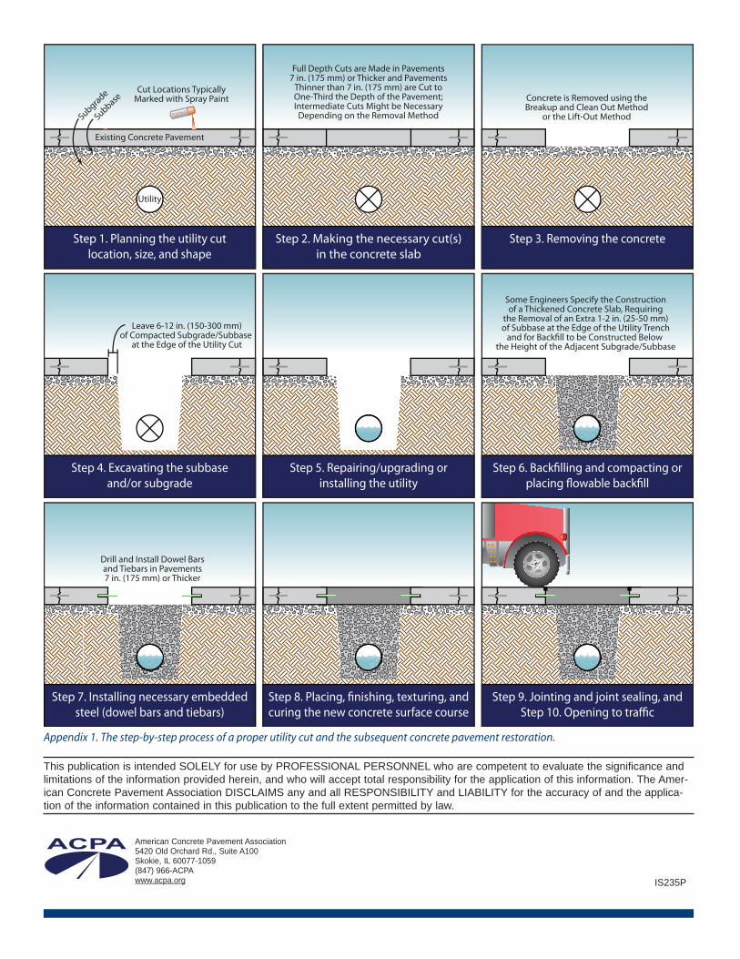
Concrete pavements have long been recognized as clean,smooth riding, strong, and durable, and properly designed andconstructed concrete pavements should provide severaldecades of zero- to low-maintenance service. At times, it isnecessary to cut trenches in some concrete pavements, particu-larly in urban areas, in order to repair or install utilities such assewers, drainage structures, water mains, gas mains and servicelines, telecommunication lines, and power conduits. Unless thecost of trenchless methods that do not disturb the pavement isjustified, the pavement must be opened up, the utility installedor repaired, and the pavement restored using a utility cutrestoration. If these operations are carried out properly (seeAppendix 1 for the step-by-step process of making a utility cut ina concrete pavement), there will be minimal impact on the pave-ment's functional serviceability, ride quality, and lifespan.
Experience has shown that it is best to repair or restore concretepavements with concrete. Proper utility cut restorations,constructed even with the surrounding pavement, provide asmooth transition that can withstand traffic loads without futuresettlement. Flowable backfill, a material that solidifies in aboutfour hours, and/or a fast-setting concrete mixture that can carrytraffic in four hours or less can be specified; precast concretepanels might even be used to further expedite the most time-sensitive utility cut restorations.
The purpose of this publication is to provide guidance for thecity engineer, public works supervisor, utility foreman, orcontractor who must plan or carry out a utility cut and thesubsequent utility cut restoration. This publication describessimple design and construction techniques, which usually donot involve any specialized equipment, contractors, or materials;these techniques apply primarily to utility cut restorations inlight-truck-traffic roadways, such as residential and collectorstreets. Exceptions to these techniques for specialty situations,such as utility cuts in overlays, are included in the "Other DesignConsiderations" section.
� Planning the Utility Cut Location, Size,and ShapeThe first step is to plan the location, size, and shape of the utilitycut after the location of the new or existing utility is identified.
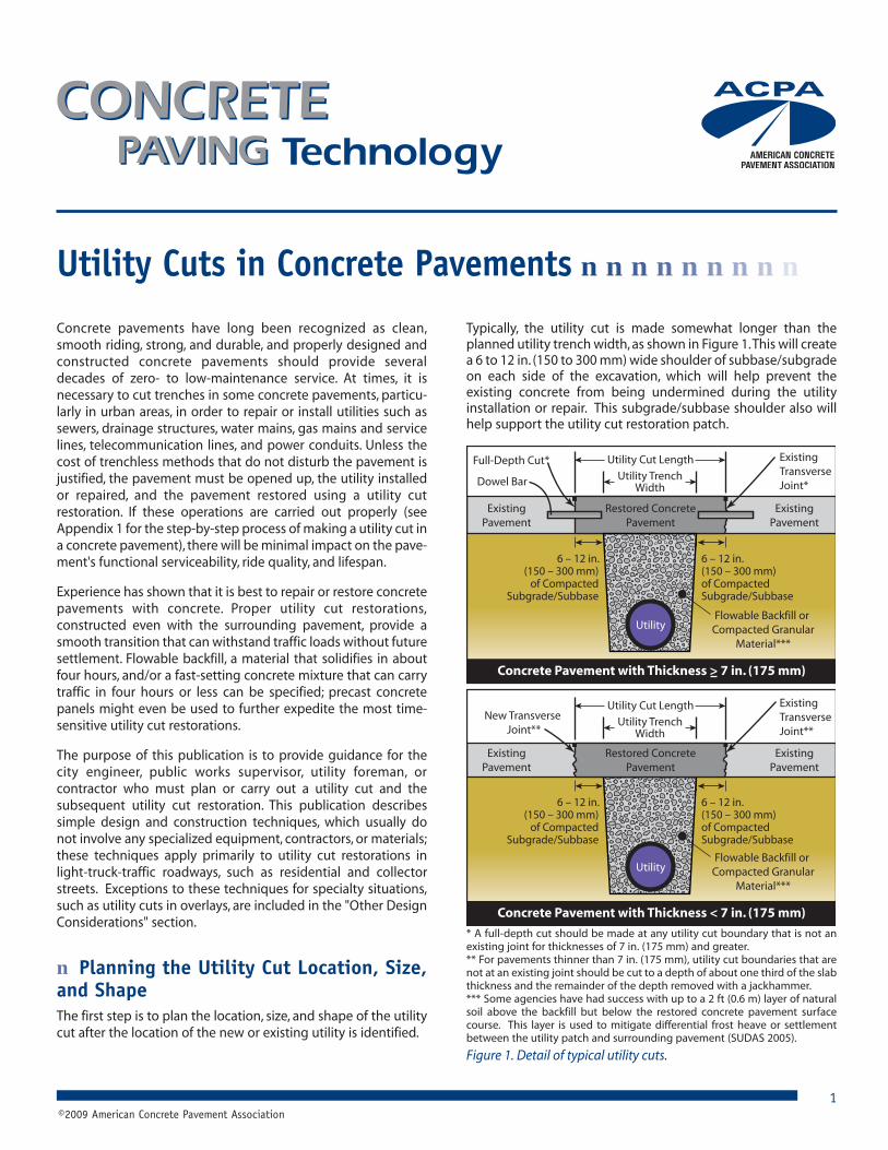
Typically, the utility cut is made somewhat longer than theplanned utility trench width, as shown in Figure 1. This will createa 6 to 12 in. (150 to 300 mm) wide shoulder of subbase/subgradeon each side of the excavation, which will help prevent theexisting concrete from being undermined during the utilityinstallation or repair. This subgrade/subbase shoulder also willhelp support the utility cut restoration patch.
Utility Cuts in Concrete Pavements ���������
©2009 American Concrete Pavement Association
Utility
ExistingPavement
ExistingPavement
Restored ConcretePavement
Flowable Backfill or Compacted Granular
Material***
6 – 12 in.(150 – 300 mm)
of CompactedSubgrade/Subbase
6 – 12 in.(150 – 300 mm)of CompactedSubgrade/Subbase
Utility Cut Length
Utility TrenchWidth
Existing TransverseJoint*
Concrete Pavement with Thickness > 7 in. (175 mm)
Dowel Bar
Utility
ExistingPavement
ExistingPavement
Flowable Backfill or Compacted Granular
Material***
6 – 12 in.(150 – 300 mm)
of CompactedSubgrade/Subbase
6 – 12 in.(150 – 300 mm)of CompactedSubgrade/Subbase
Utility Cut Length
Utility TrenchWidth
Existing TransverseJoint**
Concrete Pavement with Thickness < 7 in. (175 mm)
Full-Depth Cut*
New Transverse Joint**
Restored ConcretePavement
Figure 1. Detail of typical utility cuts.
1
* A full-depth cut should be made at any utility cut boundary that is not anexisting joint for thicknesses of 7 in. (175 mm) and greater.** For pavements thinner than 7 in. (175 mm), utility cut boundaries that arenot at an existing joint should be cut to a depth of about one third of the slabthickness and the remainder of the depth removed with a jackhammer.*** Some agencies have had success with up to a 2 ft (0.6 m) layer of naturalsoil above the backfill but below the restored concrete pavement surfacecourse. This layer is used to mitigate differential frost heave or settlementbetween the utility patch and surrounding pavement (SUDAS 2005).
If the utility cut is to be made in a concrete pavement that is 7 in.(175 mm) or thicker, dowel bars are required for load transfer,rendering aggregate interlock unnecessary. As such, full-depthsawcuts can be made at any utility cut boundary that is not at anexisting joint to ease removal. Depending on the concreteremoval method and if any boundaries of the utility cut are atexisting joints, buffer cuts might also be used to protect theutility cut perimeters from surface spalling and/or undercuttingof the existing slab during removal of the section.
When making a rectangular or square utility cut, the cuts shouldbe perpendicular, straight lines at the edge of the utility cut(Figure 4); round utility cuts are made through the full-depth ofthe concrete, similar to typical coring operation. Saw cuts arepreferable to line drilling because they create a clean edge andwill minimize the potential for long-term spalling around theutility cut boundaries.
2
Utility Cut Length
Utility TrenchWidth
Chipped EdgesTaper Inward
6 - 12 in. (150 - 300 mm)of Compacted Subbase
Utility Cut Length
Utility TrenchWidth
UndercutSpall
No Rim
Good Practice
Poor Practice
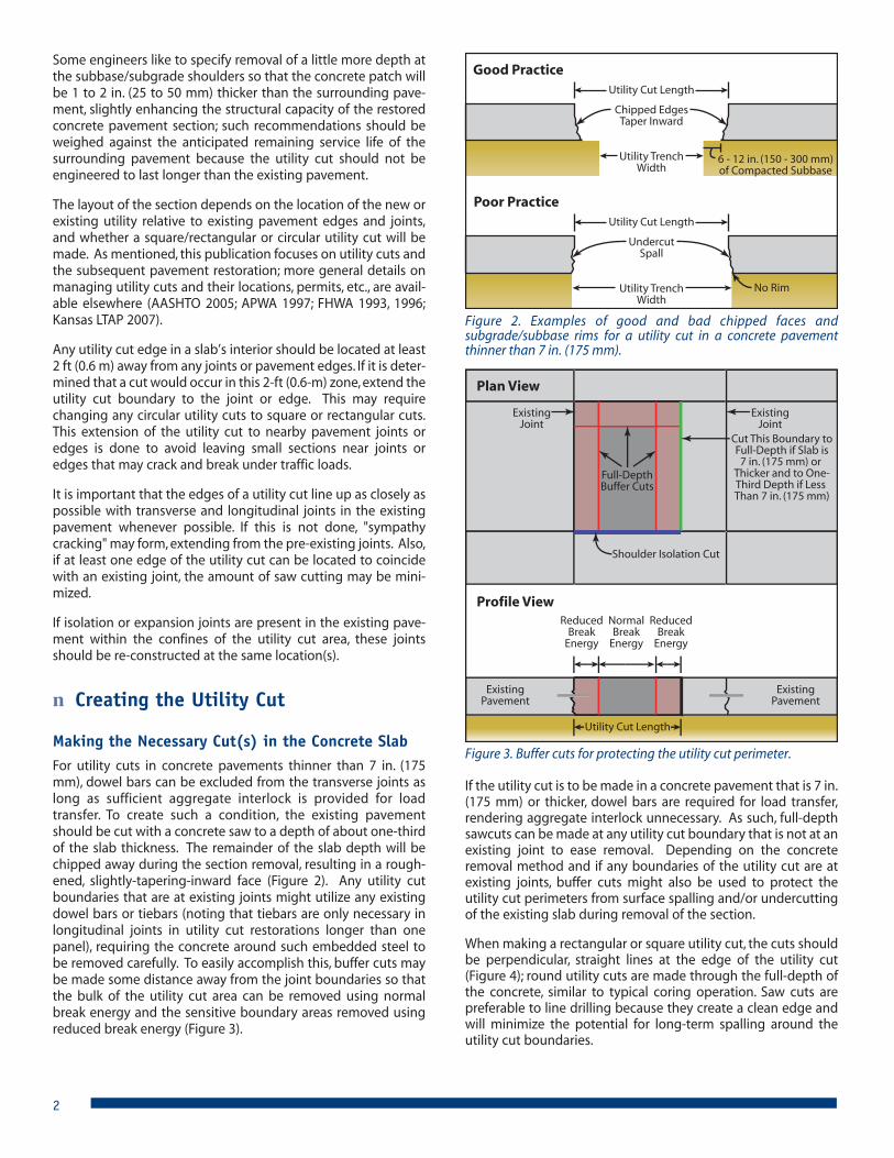
Figure 2. Examples of good and bad chipped faces andsubgrade/subbase rims for a utility cut in a concrete pavementthinner than 7 in. (175 mm).
Some engineers like to specify removal of a little more depth atthe subbase/subgrade shoulders so that the concrete patch willbe 1 to 2 in. (25 to 50 mm) thicker than the surrounding pave-ment, slightly enhancing the structural capacity of the restoredconcrete pavement section; such recommendations should beweighed against the anticipated remaining service life of thesurrounding pavement because the utility cut should not beengineered to last longer than the existing pavement.
The layout of the section depends on the location of the new orexisting utility relative to existing pavement edges and joints,and whether a square/rectangular or circular utility cut will bemade. As mentioned, this publication focuses on utility cuts andthe subsequent pavement restoration; more general details onmanaging utility cuts and their locations, permits, etc., are avail-able elsewhere (AASHTO 2005; APWA 1997; FHWA 1993, 1996;Kansas LTAP 2007).
Any utility cut edge in a slab’s interior should be located at least2 ft (0.6 m) away from any joints or pavement edges. If it is deter-mined that a cut would occur in this 2-ft (0.6-m) zone, extend theutility cut boundary to the joint or edge. This may requirechanging any circular utility cuts to square or rectangular cuts.This extension of the utility cut to nearby pavement joints oredges is done to avoid leaving small sections near joints oredges that may crack and break under traffic loads.
It is important that the edges of a utility cut line up as closely aspossible with transverse and longitudinal joints in the existingpavement whenever possible. If this is not done, "sympathycracking" may form, extending from the pre-existing joints. Also,if at least one edge of the utility cut can be located to coincidewith an existing joint, the amount of saw cutting may be mini-mized.
If isolation or expansion joints are present in the existing pave-ment within the confines of the utility cut area, these jointsshould be re-constructed at the same location(s).
� Creating the Utility Cut
Making the Necessary Cut(s) in the Concrete SlabFor utility cuts in concrete pavements thinner than 7 in. (175mm), dowel bars can be excluded from the transverse joints aslong as sufficient aggregate interlock is provided for loadtransfer. To create such a condition, the existing pavementshould be cut with a concrete saw to a depth of about one-thirdof the slab thickness. The remainder of the slab depth will bechipped away during the section removal, resulting in a rough-ened, slightly-tapering-inward face (Figure 2). Any utility cutboundaries that are at existing joints might utilize any existingdowel bars or tiebars (noting that tiebars are only necessary inlongitudinal joints in utility cut restorations longer than onepanel), requiring the concrete around such embedded steel tobe removed carefully. To easily accomplish this, buffer cuts maybe made some distance away from the joint boundaries so thatthe bulk of the utility cut area can be removed using normalbreak energy and the sensitive boundary areas removed usingreduced break energy (Figure 3).
ExistingPavement
ExistingPavement
Utility Cut Length
NormalBreak
Energy
ReducedBreak
Energy
ReducedBreak
Energy
Profile View
Plan View
Full-DepthBuffer Cuts
ExistingJoint
ExistingJoint
Cut This Boundary toFull-Depth if Slab is7 in. (175 mm) or
Thicker and to One-Third Depth if Less Than 7 in. (175 mm)
Shoulder Isolation Cut
Figure 3. Buffer cuts for protecting the utility cut perimeter.
During hot weather, the sawing equipment may bind duringinitial sawing, so it may be helpful to perform sawing at nightwhen the temperatures are lower and the slabs are contracted(also when the traffic volume is lower). Another solution is toprovide one or more transverse sawcuts in the area to beremoved, similar to those made for buffer cuts (see Figure 3). Ifthe saws continue to bind, yet another solution, if the contractorhas the equipment readily available, is to use a carbide toothedwheel saw (or kerf saw) to provide a pressure relief cut within thepatch area prior to boundary sawing (Figure 5). Such pressurerelief cuts might also be used to ease breaking and removal ofthe concrete in the utility restoration area (Figure 6).
Removing the ConcreteRemoval procedures should not spall or crack adjacent concreteslabs. If they do, the utility cut restoration area might need to beexpanded to ensure that the boundary is free of major surfacedefects.
The concrete in the removal section typically is removed usingthe breakup and cleanout method. This is normally accom-plished using a jackhammer or, for larger areas, a pavementbreaker to break the slab(s), followed by removal of the piecesusing a backhoe. Breakup should begin in the center of theremoval area using normal break energy and, as the breakoutoperation nears the saw-cut boundary of the utility cut area, areduced breaking energy, which might include switching to alighter, hand-held jackhammer (see Figure 6).
If the pavement is thinner than 7 in. (175 mm), special careshould be taken to obtain a slightly-tapering-inward cut for alltransverse joints that are not at existing joints (see Figure 2). Arough, irregular face below the saw cut is desirable to promoteload transfer across the transverse joints in these thin pave-ments.
Regardless, the method of breaking the removal section shouldnot damage the adjacent pavement or overbreak/undercut theslab bottom resulting in a cone or pyramid-shaped patch withpoor load transfer and an increased potential for punchout ofthe utility cut restoration section.
An alternate method of removing the concrete is the lift-outmethod, in which full or partial slabs are lifted out of place. Afterthe area to be removed is isolated by full-depth saw cuts, holesare drilled through the slab and fitted with lift pins. The slab isthen lifted and removed in one or more pieces by some type ofheavy equipment (e.g., a backhoe or front-end loader) with achain attached to the lift pins (Figure 7). Alternatively, a claw-likeattachment that slides beneath the concrete slab and grabs itbefore lifting may be used (Figure 8). Regardless of which lift-outmethod is used, care should be taken to lift out the slab(s) asvertically as possible to prevent the slab from binding andspalling the adjacent pavement. Because both lift out methodsrequire full-depth sawcuts around the perimeter of the utilitycuts, it makes this method the ideal, quickest way to removeutility cut sections in pavements that are 7 in. (175 mm) orthicker. The lift-out method also is the preferred removalmethod for circular utility cuts because it often allows for theintact core to be retained and replaced as a pseudo-precast slabsection.
If completed correctly, both lift-out operations leave a smooth,undamaged joint face. Although both lift-out methods typicallyare faster than the breakup and clean-out methods, the lift-outmethods require some special equipment.
3
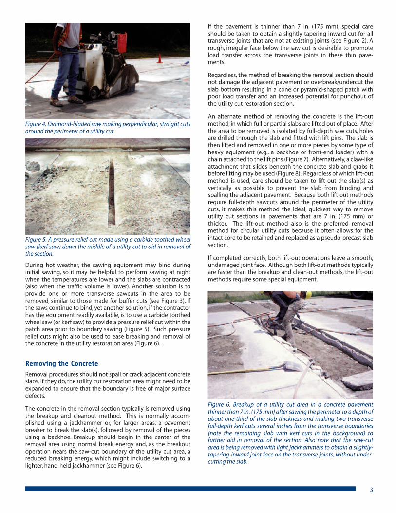
Figure 4. Diamond-bladed saw making perpendicular, straight cutsaround the perimeter of a utility cut.
Figure 5. A pressure relief cut made using a carbide toothed wheelsaw (kerf saw) down the middle of a utility cut to aid in removal ofthe section.
Figure 6. Breakup of a utility cut area in a concrete pavementthinner than 7 in. (175 mm) after sawing the perimeter to a depth ofabout one-third of the slab thickness and making two transversefull-depth kerf cuts several inches from the transverse boundaries(note the remaining slab with kerf cuts in the background) tofurther aid in removal of the section. Also note that the saw-cutarea is being removed with light jackhammers to obtain a slightly-tapering-inward joint face on the transverse joints, without under-cutting the slab.
Excavating the Subbase and/or SubgradeAfter the concrete has been broken and removed, the excavationis made to the utility or fixture that is to be replaced or repairedor to the depth necessary for the installation of the new utility.This may be done using a backhoe or skid steer loader, by hand,using a specialized vacuum, or by any other acceptable means.
The need for shoring to prevent cave-ins of the trench willdepend upon the type of subgrade soil, its condition at the timeof excavation, and the depth of the utility trench. The contractormust have a good knowledge of the soils under the pavementand make this determination based on the current local andfederal specifications or regulations governing excavating tech-niques.
� Repairing/Upgrading or Installing theUtilityThe utility is repaired or upgraded upon excavation, or a newutility is installed, using the appropriate procedures.
� Preparing the Utility Cut AreaReconstructing a subgrade/subbase and the subsequent instal-lation of any necessary dowel bars or tiebars are the two primarykeys to proper preparation of the utility cut area. Thesubgrade/subbase might be backfilled and compacted withnative or borrow material (possibly containing recycled concreteaggregate (RCA)), or the area might be filled with a flowablebackfill (again potentially utilizing RCA). Dowel bars are notnecessary for utility cut restorations in pavements thinner than 7in. (175 mm). If the pavement thickness is 7 in. (175 mm) orgreater, however, dowels must be drilled and installed into theexisting adjacent pavement at transverse joints along theboundary of the utility cut and dowel baskets must be installedat any transverse joints in the utility cut if it is longer than oneslab. Tiebars should be included in longitudinal joints that abutexisting concrete pavements (and in interior longitudinal joints)in portions of the utility cut restoration area that are longer thanone slab and a bond breaker might be used in such longitudinaljoints in sections where the joint is less than one slab long.
As noted, it may be desirable to construct the utility cut concretepatch 1 to 2 in. (25 to 50 mm) thicker than the existing concretefor extra structural capacity of the restored concrete pavementstructure, requiring slightly more subgrade/subbase to beremoved between the perimeter of the utility cut trench and theutility cut; this should be done as part of the preparation of theutility cut area so that this lower elevation can be referencedwhen placing the backfill.
Some engineers recommend two additional cuts at the trans-verse boundaries of the utility cut area approximately 6 to 12 in.(150 to 300 mm) beyond the limits of the excavation after theutility cut trench has been backfilled/compacted (NCPTC 2008).This provides shouldering if sloughing of the trench hasoccurred during utility installation/repair. Such a precautionprovides an even larger area of well-compactedsubgrade/subbase to better ensure that the ends of the utilitycut repair are supported. If done, the additional boundary cut(s)and the necessary hand-held jackhammer work should beperformed prior to drilling any holes in the adjacent pavementfor dowel bars. If a thickened slab is used in this scenario,removal of the top 1 to 2 in. (25 to 50 mm) of subgrade/subbasewould be necessary prior to installation of dowel bars to ensurethat the thickened slab is constructed to the boundaries of theutility cut area.
Backfilling with Granular Material and CompactingSettlement of utility cut restorations in pavements is a prevalentproblem that can be avoided by careful construction and inspec-tion during backfilling operations. While concrete is morecapable of bridging a slight settlement than other paving mate-rials, it is, nonetheless, wise to pay particular attention to thebackfill specifications and construction procedures.
When backfilling a utility trench, every attempt should be madeto achieve adequate compaction of the backfill material so thatit will not settle when in service. In the past, this often involvedbackfilling with previously removed material and tamping thismaterial in 6-in. (150-mm) lifts at the proper moisture contentand density. However, proper compaction of silt-clay soils in autility cut trench is difficult, especially during wet weather.
4
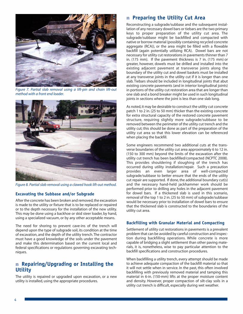
Figure 7. Partial slab removal using a lift-pin and chain lift-outmethod with a front end loader.
Figure 8. Partial slab removal using a clawed hook lift-out method.

Today, many public works engineers prefer removing all fine-grained soil at the time of excavation and replacing it withcement-treated sand/soil or a select granular material. If used,select granular material must be free of frozen lumps and rockslarger than 4 in. (100 mm) in diameter. As with any un- orpartially-stabilized backfill material, adequate compaction (95%of density as determined by ASTM D698/AASHTO T99) is criticalto prevent later settlement.
A cement-treated sand or soil will usually pay dividends to boththe contractor and the municipality by ensuring higher, moreuniform support, further preventing future settlement of thepatch. The amount of cement used in such compacted mixturesshould be only enough to "cake" the material rather than toproduce a hardened soil-cement. Soils treated with lime or anyother acceptable soil stabilizing material also may be used andshould be compacted in layers at the proper moisture content.
Depending on the duration between compaction of thesubgrade/subbase and the time when the concrete is going tobe placed, it might be necessary to recompact thesubgrade/subbase immediately prior to placement of the newconcrete surface course (Figure 9).
Placing Flowable BackfillFlowable backfill is an ideal alternative to subgrade/subbasereconstruction for utility cuts. Flowable backfill is a low-strength,self leveling material made with cement, supplementary cemen-titious materials (SCMs; e.g., fly ash, slag cement, silica fume, etc.),sand (possibly fine RCA), and water that easily flows and fills theutility cut area, then hardens. Because it is designed not tobecome too hard, it is easy to remove later but, because it is soflowable, it requires some means of containment while it sets up.
In addition to its fast setup time—usually within a few hours—flowable backfill has many advantages over compacted soil andgranular backfills. Flowable backfill, available from ready mixedconcrete plants in most locations, hardens to a degree thatprecludes any future trench settlement.
Many terms are presently used to describe this type of backfillmaterial: flowable fill, unshrinkable fill, controlled-density fill,flowable mortar, and various trade names. Controlled Low-Strength Materials (CLSM) is the technical general term thatemerged through ACI Committee 229 (ACI 1999), although theterm flowable backfill tends to still be more commonly used.
Flowable backfill has the advantage of being a standard, well-controlled material, mixed at a plant, transported to the site in aready mix truck, or, on small jobs, delivered dry to a mobile mixer.In its application for backfill, the material is designed to have avery low strength compared to conventional concrete.
A typical flowable backfill mixture consists of about 60 lb/yd3 (35kg/m3) of cementitious materials and fine and coarse aggregate,with a slump up to about 8 in. (200 mm). A minimum strength of10 psi (0.07 MPa) at 24 hours typically is required and the 28-daycompressive strength specification typically is in the range of 50to 100 psi (0.35 to 0.70 MPa); this ensures that, if necessary, it canbe easily removed later using normal excavation tools andequipment. As such, it is important not to use too much cementor SCMs so long-term strength gain does not become excessive.
5
Because flowable backfill is a self-leveling, flowable material, itcan be poured into the utility trench, requiring no compaction,as shown in Figure 10. The trench is filled with the flowablematerial up to the level where the bottom of the new concretesurface course will be constructed. Typically, the material solidi-fies sufficiently to support loads or have the concrete surfacecourse placed in about 4 hours.
If the utility is not filled with fluid or is not neutrally buoyant rela-tive to the flowable fill, it might be necessary to either secure theutility against possible floating due to buoyancy of the emptypipe or place the flowable fill in two layers: the first layer fillingthe trench up to the bottom of the pipe and the second layer,placed only after the first has set up, filling the rest of the utilitytrench. Alternatively, the utility can be bedded in a granularmaterial, rather than flowable fill, up to at least half of the pipedepth.
Figure 9. Recompaction of backfill immediately prior to placementof the new concrete surface course. Note that all other necessarypreparation work has been completed, such as the dowel barsalready having been drilled and installed.
Figure 10. Placement of flowable backfill in a utility cut. Note thatthe flowable material is self-leveling, with the top of the backfillbeing placed to the base of the existing adjacent concrete slab[Photo courtesy of the Cincinnati Ready-Mix Concrete Company].
6
Use of flowable backfill along with high early strength concretepatches or precast concrete panels—discussed later—becomesimportant where there is a need to restore the pavement quicklyto minimize traffic disruption. The extra cost for the material,compared to compacted backfill, is offset by the fact that it elim-inates the costs for compaction and labor, reduces themanpower required for close inspection of the backfill opera-tion, requires less trench width, and reduces the time and costfor traffic control and public protection measures.
The performance of flowable backfill has generally exceededthat of compacted backfills with minimal problems due tosettlement, frost action, or localized zones of increased stiffness.It has been used extensively in the U.S. and Canada since the1970s.
Installing Necessary Embedded Steel (Dowel Barsand Tiebars)It is crucial that all necessary subgrade/subbase and/or backfillcompaction is completed prior to installing any dowel bars ortiebars because once the dowel bars and/or tiebars are installedit will be difficult to maneuver compaction equipment aroundthem at the edges of the utility cut area.
Load transfer is the ability of a utility cut restoration section totransfer part of its load to the adjacent concrete. Re-establishingload transfer across any transverse joint on the perimeter of autility cut is one of the most critical factors affecting long-termperformance of the section. Good load transfer reduces thestresses on the patch and prevents it from rocking and moving.
For utility cut restorations in pavements thinner than 7 in. (175mm), it is possible to obtain sufficient long-term load transferwith just aggregate interlock. Aggregate interlock load transferis derived from the interlocking action between the roughenedface of the in-place concrete and the face of the cast-in-placepatch. As discussed, to create the roughened face, the crewremoves the existing concrete along the transverse boundariesof the utility cut with a light pneumatic hammer to create aroughed, slightly-tapering-inward edge. If a concrete pavementthinner than 7 in. (175 mm) included dowels in the originaldesign then dowels might be included as part of the utility cutrepair but such recommendations should be weighed againstthe anticipated remaining service life of the surrounding pave-ment because the utility cut should not be engineered to lastlonger than the existing pavement.
For utility cut restorations in pavements 7 in. (175 mm) or thicker,load transfer typically is best achieved by a sufficient size andnumber of properly installed dowel bars. Dowel bars are smooth,round bars that extend from one side of a joint to the other,transferring the load across the joint. Dowels improve pavementperformance by:
� Helping maintain the alignment of adjoining slabs.
� Providing load transfer across joints, while at the same timeallowing the joint to open and close as the surroundingpavement expands and contracts in response to tempera-ture and moisture changes.
� Limiting or reducing stresses that result from loads on thepavement.
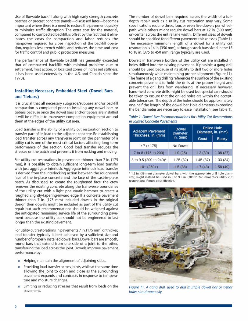
The number of dowel bars required across the width of a full-depth repair such as a utility cut restoration may vary. Somespecifications require three, four, or even five dowels per wheel-path while others might require dowel bars at 12 in. (300 mm)on-center across the entire lane width. Different sizes of dowelsshould be specified for different pavement thicknesses (Table 1).The necessary minimum length of a dowel for a utility cutrestoration is 14 in. (350 mm), although stock bars sized in the 15to 18 in. (375 to 450 mm) range typically are used.
Dowels in transverse borders of the utility cut are installed inholes drilled into the existing pavement. If possible, a gang drillshould be used because of its ability to drill two or more holessimultaneously while maintaining proper alignment (Figure 11).The frame of a gang drill rig references the surface of the existingconcrete pavement to hold the drills at the proper height andprevent the drill bits from wandering. If necessary, however,hand-held concrete drills might be used but special care shouldbe taken to ensure that the drilled holes are within the accept-able tolerances. The depth of the holes should be approximatelyone-half the length of the dowel bar. Hole diameters exceedingthe bar diameter are necessary to ease installation (see Table 1).
Figure 11. A gang drill, used to drill multiple dowel bar or tiebarholes simultaneously.
Table 1. Dowel Size Recommendations for Utility Cut Restorationsin Jointed Concrete Pavements
* 1.5 in. (38 mm) diameter dowel bars, with the appropriate drill hole diam-eter, might instead be used in 8 to 9.5 in. (200 to 240 mm) thick utility cutrestorations if more cost effective.
Adjacent PavementThickness, in. (mm)
Dowel Diameter, in. (mm)
Drilled Hole Diameter, in. (mm)
Grout Epoxy
≤ 7 (≤ 175) No Dowel - -
7 to 8 (175 to 200) 1.0 (25) 1.2 (30) 1.08 (27)
8 to 9.5 (200 to 240)* 1.25 (32) 1.45 (37) 1.33 (34)
10+ (250+) 1.5 (38) 1.7 (43) 1.58 (40)

7
� Restoration of the Utility Cut
Design of Concrete Mixtures for Utility Cuts The concrete mixture requirements for a utility cut primarilydepend on the required strength before opening of the area totraffic (see the section titled “Opening to Traffic” for minimumopening strength recommendations). Local ready mixedconcrete producers should be able to recommend concretemixtures that will be suitable to match the project requirements.Both coarse and fine RCA can be utilized in concrete mixtures forutility cuts.
If it is acceptable for the concrete to cure for several days (similarto new construction), standard concrete mixtures with a Type Icement will be sufficient. If an accelerated opening is required, ahigh early strength cement (Type III or Type HE) can be used orthe cement content (not the same as the cementitious materialscontent) may be increased to as much as 650 to 850 lb/yd3 (380to 500 kg/m3) of Type I or Type GU cement. Proprietary, rapid-setcementitious materials and blended cements also are available;some can reach sufficient strength for traffic in as little as fourhours. These materials should be used in compliance with themanufacturer’s recommendations for bonding, placing, curing,opening to traffic requirements, and placement temperatureranges. An accelerating admixture also is frequently added toutility cut restoration mixtures to achieve strengths earlier. Extracare may be necessary, however, to properly cure the utility cutrestoration when using an accelerating admixtures and/or highearly strength cement.
All concrete placement techniques should follow standardprocedures. Where opening to traffic is critical, concrete mixturesshould be tested for strength and strength gain properties at theapproximate temperature in which it will be placed. A maturitycurve may be developed before placing the concrete to helpdetermine the earliest time for opening the utility repair area.(See the section titled “Opening to Traffic” for more details onthe maturity method for early estimation of in-place strength).
In freeze-thaw climatic areas where deicing compounds areapplied to pavements to melt snow and ice, it is imperative thatair-entrained concrete be used. Failure to do so will frequentlyresult in slab scaling. The amount of entrained air necessarydepends on the maximum size of the aggregate in the concrete(Table 2). In addition to providing resistance to freezing andthawing and the action of deicer salts, entrained air improves theworkability and ease of consolidation of the concrete utility cutrestoration material. More general details on designing concretepaving mixtures that are resistant to freeze-thaw damage areavailable elsewhere (PCA 2002, FHWA 2006).
The first step in installing dowel bars is to place grout (cementi-tious or epoxy) into the back of each hole (Figure 12). Thisensures that the material flows out around each bar, fullyencasing it. Do not coat one end of the bar with grout or epoxyand then insert the bar into the hole – the air pressure inside thehole will force the grouting material back out of the hole, leavinga void around the bar. The end of the bar that extends into theutility cut area should have a bond breaker applied to it toprevent bonding with the patch material. This bond breaker maybe applied by the manufacturer or may be field-applied.
If the repair is large enough to require transverse joints in theinterior of the repair area, a contraction joint with dowels isnecessary in pavements that are 7 in. (175 mm) or thicker; thesedowels are installed using dowel baskets.
Deformed tiebars have surface ridges that provide a lockinganchorage when embedded in concrete. In contrast to dowelbars, tiebars are not designed to assist with load transfer but,rather, are designed to prevent opening of longitudinal joints atthe utility cut/existing pavement interface or within the utilitycut. Sections of a utility cut restoration that are longer than oneslab, or utility cuts in pavements that have tiebars, shouldinclude tiebars of a diameter and spacing that complies withlocal requirements; utility cut restorations that are not as long asone slab may be isolated from the adjacent pavement by theinclusion of a bond breaker in the longitudinal joint. Tiebars areinstalled in much the same manner as dowel bars, with holesbeing drilled in the longitudinal joint of the existing pavementat a prescribed spacing, diameter and depth, and tiebars beingepoxied or grouted into the holes. A bond breaker is not appliedto tiebars because a bond with the concrete is desirable.
Be sure that all dowel bars and/or tiebars are clean, free offlaking rust, and are epoxy-coated or otherwise non-corrosiveprior to their installation.
Utility cuts in continuously reinforced concrete pavement(CRCP) are rare because CRCP typically is only used on highways.Should a utility cut be necessary in a CRCP, the procedure to re-establish load transfer (and the continuous reinforcement) issimilar to CRCP patching. Guidelines for the necessary lapdistance for various splicing techniques to reestablish thecontinuous reinforcing in full-depth CRCP repairs are availableelsewhere (ACPA 1995).
1
2
3
Inject groutto the back of the hole.
Twist one turn whilepushing the dowelinto the hole.
Place grout retentiondisk to hold in grout(optional).
Figure 12. Steps for installing dowels in drilled holes in an existingconcrete pavement.
Table 2. Recommendations for Percent Entrained Air Based onMaximum Aggregate Size
Maximum aggregate size, in. (mm)
Entrained air, %
1 ½ (38) 5 ½ ± 1
¾ (19) or 1 (25) 6 ± 1
½ (13) 7 ± 1
38 (9.5) 7 ½ ± 11
8
Normal strength concrete, high early strength concrete, andproprietary materials all have been used successfully as mate-rials for utility cut restorations; asphalt concrete is not a goodmaterial for utility cut restorations in concrete pavements.Asphalt has different thermal properties than concrete, and it isnot as durable. Using asphalt in a utility repair area in a concretepavement can lead to roughness from heaving or settling, andcan compromise the utility.
Placing, Finishing, Texturing, and Curing the NewConcrete Surface Course Before placing concrete into the utility cut area, any loosesubgrade/subbase material should be firmly compacted withhand or pneumatic tools. The exposed faces of existing jointsthat will still serve as working joints should be coated with formoil or a curing compound to prevent bonding to the newconcrete. Also, a fiber-board bond breaker might need to beinstalled between the longitudinal joints of the existingconcrete and the repair when the joint is not longer than oneslab (Figure 13).
Concrete placed in the utility cut restoration area should be wellconsolidated using hand tools or internal vibrators to ensurethat there are no voids under or adjacent to the existing pave-ment (proper mixture design is a critical variable in ensuringadequate consolidation along the perimeter of the utility cut) orbeneath any embedded steel (Figure 14). Ambient temperaturesshould be between 40° and 90°F (4° and 32°C) for any concreteplacement, otherwise the appropriate hot or cold weatherconcreting practices should be employed. The slump ofconcrete for utility cut restoration mixtures should be in therange of 3 to 5 in. (75 to 125 mm) to ensure proper consolidationand to permit manual finishing with a manual or vibratingscreed.
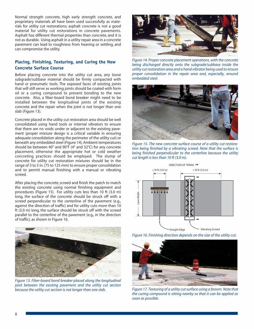
After placing the concrete, screed and finish the patch to matchthe existing concrete using normal finishing equipment andprocedures (Figure 15). For utility cuts less than 10 ft (3.0 m)long, the surface of the concrete should be struck off with ascreed perpendicular to the centerline of the pavement (e.g.,against the direction of traffic) and for utility cuts more than 10ft (3.0 m) long, the surface should be struck off with the screedparallel to the centerline of the pavement (e.g., in the directionof traffic), as shown in Figure 16.
Figure 13. Fiber-board bond breaker placed along the longitudinaljoint between the existing pavement and the utility cut sectionbecause the utility cut section is not longer than one slab.
Figure 14. Proper concrete placement operations, with the concretebeing discharged directly onto the subgrade/subbase inside theutility cut restoration area and a hand vibrator being used to ensureproper consolidation in the repair area and, especially, aroundembedded steel.
Figure 17. Texturing of a utility cut surface using a broom. Note thatthe curing compound is sitting nearby so that it can be applied assoon as possible.
Figure 15. The new concrete surface course of a utility cut restora-tion being finished by a vibrating screed. Note that the surface isbeing finished perpendicular to the centerline because the utilitycut length is less than 10 ft (3.0 m).
<10 ft (3.0 m) >10 ft (3.0 m)
DIRECTION OF TRAVEL
Straight Edge
Lane
Wid
th
Vibrating Screed
Figure 16. Finishing direction depends on the size of the utility cut.

The final texturing of the surface should match the existingsurrounding pavement as closely as possible. Usually, a lightbrooming or burlap drag will be satisfactory, typically appliedonce the surface sheen has disappeared (Figure 17). To avoidslippery surfaces, smooth-steel trowels should not be used.
As with the placement of any fresh concrete, proper curing ofthe new concrete surface course is important. The patch shouldbe cured to ensure that the concrete achieves its potentialstrength and durability. It is best to begin curing operations assoon as possible after completing the finishing operationsand/or as soon as the bleed water has disappeared from thesurface of the concrete (typically within ½ hour after placementof the concrete for most paving and repair mixtures). While poly-ethylene, wet burlap, impervious paper, ponding, or constantspraying may be used for curing, a membrane-formingcompound is the most common curing method. Unlikemethods such as covering with wet burlap or a polyethylene, theapplication of a curing compound requires no uncovering at alater time, and traffic can be reinstated on the pavement soonafter placement.
To ensure the area is thoroughly coated, curing compoundsshould be either white-pigmented or tinted for visibility. A usefulrule of thumb is that proper application of a white-pigmentedcuring compound has occurred when the concrete surface is aswhite as a sheet of paper (Figure 18); any gray areas, streaks orblotches are an indication of under-application. A double appli-cation of curing compound is a good practice for repairs such asutility cut restorations. In all curing operations, make sure theentire utility cut surface and any exposed edges are covered.
For utility cuts utilizing high early strength materials that willopen quickly to traffic, insulation boards/mats will hold in heatwhile the concrete is curing. The insulating material should beplaced over a polyethylene sheet (Figure 19). In extremely coldambient conditions, care should be taken to ensure thatstrength requirements are met prior to removal of any insulationboards/mats to prevent thermal shock.
Circular utility cuts oftentimes can use the intact, removed coreas a repair, similar to a pre-cast slab. If this is done, the coreshould is oriented it in its original direction and grout used tolevel it up and bond it to the surrounding pavement (APWA2004). Specialty non-shrink grout mixtures and epoxies alsohave been used successfully to set circular utility cut cores.
Jointing and Joint Sealing Joints may be formed by use of an edging tool or parting stripsor cut later with a saw; the depth of any saw cuts should be one-fourth the slab thickness for any joints in the interior of the utilitycut restoration and the minimum depth necessary for creationof the sealant joint reservoir for joints on the perimeter of theutility cut restoration. Or, if the joint(s) are not to be sawed andsealed, the patch edges may be finished with a one-eighth-inch(3 mm) radius edging tool for a neat appearance.
Any transverse or longitudinal construction/contraction or isola-tion/expansion joints in the adjacent pavement should becontinued through the utility cut to prevent sympathy cracking.
If necessary, transverse and longitudinal joints within the utilitycut may be sawed while the concrete is green to controlcracking. If the concrete cracks before initial sawing, the resultingcrack should be prepared and sealed.
Longitudinal and transverse joints typically are sealed, particu-larly if the original pavement had sealed joints. Jointing detailssuch as commonly used sealant types and typical sealant reser-voir dimensions for the various sealant types are available else-where (ACPA 1991, 2008b).
� Opening to TrafficIt is preferred to require a minimum concrete strength prior toopening the utility cut restoration to traffic. Thanks to modernconcrete mixture technologies, a mixture can be designed andproportioned to obtain a desired strength in the time required.In most cases, the opening strengths listed in Table 3 are suffi-cient for opening to public traffic. The use of maturity methodsto estimate opening strength is recommended.
9
Figure 18. Proper application of white-pigmented membrane-forming curing compound. Note that the surface of the repair areais as white as a sheet of paper.
Figure 19. Insulation mats placed on top of polyethylene sheets toencourage a relatively quick strength gain.
Table 3. Minimum Opening Strength for Utility Cuts of VariousThicknesses and Lengths
Utility Cut Thickness,in (mm)
Compressive Strength for Opening to Traffic, psi (MPa)
Utility Cut Length < 10 ft (3.0 m)
Utility Cut Length > 10 ft (3.0 m)
6 (150) 3,000 (20.7) 3,600 (24.8)
7 (175) 2,400 (16.5) 2,700 (18.6)
8 (200) 2,150 (14.8) 2,150 (14.8)
9+ (225+) 2,000 (13.8) 2,000 (13.8)
In any case, the concrete should have at least 4,000 psi (27.6MPa) compressive strength in 28 days. Most normal paving andrepair concrete mixtures will obtain strengths of the magnitudeshown in Table 3 within 24 to 72 hours and some high earlystrength and proprietary mixtures reach such strengths in aslittle as 3 to 4 hours.
Maturity testing is one of the most useful methods to estimateearly-age strength, particularly when early opening is required. Itemploys small thermocouples or maturity probes that can bemonitored periodically or even continuously from placement inthe field, whereas compressive (or flexural) strength testingrequires testing specimens at a laboratory, making some delayinherent to such testing methods. More general details on theestimation of in-place strength using the maturity method andthe construction of a maturity curve are available elsewhere(ACPA 2008a; FHWA 2005).
� Other Design Considerations
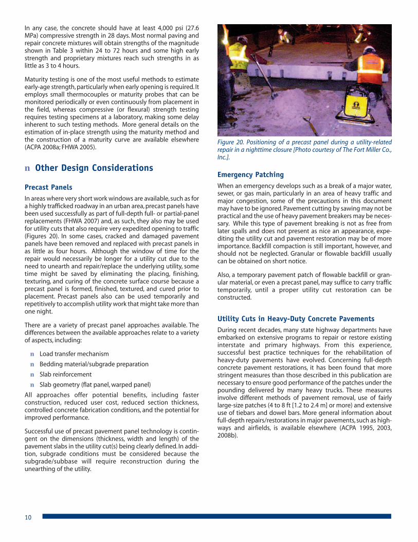
Precast PanelsIn areas where very short work windows are available, such as fora highly trafficked roadway in an urban area, precast panels havebeen used successfully as part of full-depth full- or partial-panelreplacements (FHWA 2007) and, as such, they also may be usedfor utility cuts that also require very expedited opening to traffic(Figures 20). In some cases, cracked and damaged pavementpanels have been removed and replaced with precast panels inas little as four hours. Although the window of time for therepair would necessarily be longer for a utility cut due to theneed to unearth and repair/replace the underlying utility, sometime might be saved by eliminating the placing, finishing,texturing, and curing of the concrete surface course because aprecast panel is formed, finished, textured, and cured prior toplacement. Precast panels also can be used temporarily andrepetitively to accomplish utility work that might take more thanone night.
There are a variety of precast panel approaches available. Thedifferences between the available approaches relate to a varietyof aspects, including:
� Load transfer mechanism
� Bedding material/subgrade preparation
� Slab reinforcement
� Slab geometry (flat panel, warped panel)
All approaches offer potential benefits, including fasterconstruction, reduced user cost, reduced section thickness,controlled concrete fabrication conditions, and the potential forimproved performance.
Successful use of precast pavement panel technology is contin-gent on the dimensions (thickness, width and length) of thepavement slabs in the utility cut(s) being clearly defined. In addi-tion, subgrade conditions must be considered because thesubgrade/subbase will require reconstruction during theunearthing of the utility.
Emergency PatchingWhen an emergency develops such as a break of a major water,sewer, or gas main, particularly in an area of heavy traffic andmajor congestion, some of the precautions in this documentmay have to be ignored. Pavement cutting by sawing may not bepractical and the use of heavy pavement breakers may be neces-sary. While this type of pavement breaking is not as free fromlater spalls and does not present as nice an appearance, expe-diting the utility cut and pavement restoration may be of moreimportance. Backfill compaction is still important, however, andshould not be neglected. Granular or flowable backfill usuallycan be obtained on short notice.
Also, a temporary pavement patch of flowable backfill or gran-ular material, or even a precast panel, may suffice to carry traffictemporarily, until a proper utility cut restoration can beconstructed.
Utility Cuts in Heavy-Duty Concrete PavementsDuring recent decades, many state highway departments haveembarked on extensive programs to repair or restore existinginterstate and primary highways. From this experience,successful best practice techniques for the rehabilitation ofheavy-duty pavements have evolved. Concerning full-depthconcrete pavement restorations, it has been found that morestringent measures than those described in this publication arenecessary to ensure good performance of the patches under thepounding delivered by many heavy trucks. These measuresinvolve different methods of pavement removal, use of fairlylarge-size patches (4 to 8 ft [1.2 to 2.4 m] or more) and extensiveuse of tiebars and dowel bars. More general information aboutfull-depth repairs/restorations in major pavements, such as high-ways and airfields, is available elsewhere (ACPA 1995, 2003,2008b).
10
Figure 20. Positioning of a precast panel during a utility-relatedrepair in a nighttime closure [Photo courtesy of The Fort Miller Co.,Inc.].
Utility Cuts in Concrete OverlaysBonded Concrete Overlay Over Concrete – Use a minimumutility cut restoration length of 6 ft (1.8m). Omit longitudinaltiebars on all partial length panel replacements. Place dowelbars in the underlying concrete, when required, and not theoverlay. Replace the concrete overlay with a full-depth pave-ment, matching the existing joints in the adjacent pavement.
Bonded Concrete Overlay Over Asphalt or Composite – Do nottie the utility cut restoration to the existing bonded overlay. Ifthere are dowel bars in a concrete course in an underlyingcomposite pavement, they might be included at the same depthin the utility cut restoration. Although highly unlikely, if dowelbars were used in the overlay, they might also be used in theutility cut restoration. Replace the concrete overlay with a full-depth pavement, matching the existing joints in the adjacentpavement.
Unbonded Concrete Overlay Over Concrete, Asphalt orComposite – Do not tie the utility cut restoration to the existingunbonded overlay. Replace the concrete overlay with a full-depth pavement, matching the existing joints in the adjacentpavement and doweling the utility cut restoration to match theunderlying pavement. If the utility cut restoration is approaching20 ft (6 m) in length to match the existing joint pattern, saw amid-panel transverse joint.
Utility Cuts in Pervious Concrete PavementsIf at all possible, it is best to prevent utilities from being installedor retrofitted under pervious concrete pavements throughcareful, foresightful planning of the original design of an areasurrounding and beneath a pervious concrete pavementbecause any utility beneath a pervious concrete pavementmight interfere with the percolation of water through the depthof the pervious concrete pavement structure. Pervious concretepavements also might allow for deeper penetration of the frostline, requiring many utilities to be installed at deeper-than-typical depths.
If utilities are installed or retrofitted under a pervious concretepavement and its drainage layers, precautions must be made toallow water to percolate properly through the layers and aroundthe utility and, at the same time, to protect the utility. Any utilitycut made in a previous concrete pavement will require that thebackfill and restored surface course be replaced with the appro-priate materials so that the pervious utility cut section canperform as intended. As such, construction of a utility cutrestoration in a pervious concrete pavement is required to beperformed by a National Ready Mixed Concrete Association(NRMCA) Pervious Concrete Contractor Certified Installer orCraftsman.
� References1. AASHTO 2005, A Guide for Accommodating Utilities within
Highway Right-of-Way, GAU-4, American Association ofState Highway and Transportation Officials.
2. ACI 1999, Controlled Low-Strength Materials, 229R-99,American Concrete Institute.
3. ACPA 1991, Design and Construction of Joints for ConcreteHighways, TB010P, American Concrete Pavement Associa-tion.
4. ACPA 1995, Guidelines for Full-Depth Repair, TB002P, Amer-ican Concrete Pavement Association.
5. ACPA 2003, Concrete Repair Manual for Airfields, JP002P,American Concrete Pavement Association.
6. ACPA 2008a, Concrete Pavement Field Reference: Pre-Paving, EB237P, American Concrete Pavement Association.
7. ACPA 2008b, Concrete Pavement Field Reference: Preserva-tion and Repair, EB239P, American Concrete PavementAssociation.
8. APWA 1997, Managing Utility Cuts, PB.AMUC, AmericanPublic Works Association.
9. APWA 2004, Restoration of Utility Cuts, PB.E401, AmericanPublic Works Association.
10. FHWA 1993, Highway/Utility Guide, FHWA-SA-93-049,Federal Highway Administration.
11. FHWA 1996, Utility Cuts in Paved Roads: Field Guide, FHWA-SA-97-049, Federal Highway Administration.
12. FHWA 2005, Maturity Testing for Concrete Pavement Appli-cations, FHWA-IF-06-004, Federal Highway Administration.
13. FHWA 2006, Integrated Materials and Construction Prac-tices for Concrete Pavement: A State-of-the-PracticeManual, FHWA-HIF-07-004, Federal Highway Administra-tion.
14. FHWA 2007, Precast Concrete Panel Systems for Full-DepthPavement Repairs: Field Trials, FHWA-HIF-07-019, FederalHighway Administration.
15. Kansas LTAP 2007, Guide for Accommodating UtilitiesWithin Right-Of-Way For Counties & Small Cities in Kansas,Kansas Local Technical Assistance Program.
16. NCPTC 2008, Concrete Pavement Preservation Workshop,National Concrete Pavement Technology Center.
17. PCA 2002, Design and Control of Concrete Mixtures, EB001,Portland Cement Association.
18. SUDAS 2005, Utility Cut Repair Techniques – Investigationof Improved Cut Repair Techniques to Reduce Settlementin Repaired Areas, IHRB Project TR-503, Statewide UrbanDesign and Specifications (Iowa).
11
Existing Concrete Pavement
Subgrade
Utility
Cut Locations TypicallyMarked with Spray Paint
Subbase
Full Depth Cuts are Made in Pavements7 in. (175 mm) or Thicker and Pavements
Thinner than 7 in. (175 mm) are Cut toOne-Third the Depth of the Pavement;Intermediate Cuts Might be Necessary
Depending on the Removal Method
Concrete is Removed using theBreakup and Clean Out Method
or the Lift-Out Method
Leave 6-12 in. (150-300 mm)of Compacted Subgrade/Subbase
at the Edge of the Utility Cut
Step 3. Removing the concreteStep 2. Making the necessary cut(s) in the concrete slab
Step 1. Planning the utility cut location, size, and shape
Step 4. Excavating the subbase and/or subgrade
Step 5. Repairing/upgrading or installing the utility
Step 6. Back!lling and compacting or placing "owable back!ll
Step 8. Placing, !nishing, texturing, and curing the new concrete surface course
Drill and Install Dowel Barsand Tiebars in Pavements7 in. (175 mm) or Thicker
Some Engineers Specify the Constructionof a Thickened Concrete Slab, Requiring
the Removal of an Extra 1-2 in. (25-50 mm)of Subbase at the Edge of the Utility Trench
and for Back!ll to be Constructed Below the Height of the Adjacent Subgrade/Subbase
Step 9. Jointing and joint sealing, andStep 10. Opening to tra#c
Step 7. Installing necessary embedded steel (dowel bars and tiebars)
Appendix 1. The step-by-step process of a proper utility cut and the subsequent concrete pavement restoration.
IS235P
American Concrete Pavement Association5420 Old Orchard Rd., Suite A100Skokie, IL 60077-1059(847) 966-ACPAwww.acpa.org
This publication is intended SOLELY for use by PROFESSIONAL PERSONNEL who are competent to evaluate the significance andlimitations of the information provided herein, and who will accept total responsibility for the application of this information. The Amer-ican Concrete Pavement Association DISCLAIMS any and all RESPONSIBILITY and LIABILITY for the accuracy of and the applica-tion of the information contained in this publication to the full extent permitted by law.