Embed Size (px)
Citation preview

Burlington Northern Santa Fe
UTILITY ACCOMMODATION POLICY
Engineering Services 4515 Kansas Avenue
Kansas City, KS 66106 May 18, 2011

TABLE OF CONTENTS PART 1 - GENERAL POLICY A. Policy Application 1-1 B. Utility License Agreement Requirements 1-3 C. Safety 1-5 D. Maintenance and Servicing Utilities 1-6 E. Preservation, Restoration and Cleanup 1-7 F. Protection of Vegetation 1-7 PART 2 - UTILITIES PARALLELING RAILROAD PROPERTY A. General Provisions 2-1 B. Overhead Installations 2-1 C. Underground Installations 2-2 D. Attachment to Bridges and Other Structures 2-3 E. Drains for Steep Slopes (Tight Lines) 2-3 PART 3 - UTILITIES CROSSING RAILROAD PROPERTY A. General Provisions 3-1 B. Overhead Installations 3-1 C. Underground Installations 3-2 PART 4 - PLANS, APPROVALS AND PROCEDURES A. Plans and Approvals 4-1 B. License Procedures 4-2 C. Construction 4-2 PART 5 - APPENDIX Application for Pipelines A-1 Application for Wirelines A-2 Application for Environmental Access A-4 Application to Conduct Seismic Survey A-5 Applicant’s Pipeline Crossing Checklist A-6 Underground Cable Locate Form A-7 Horizontal Directional Drilling Standard A-8 Retirement of Pipeline A-9 Drains for Steep Slopes (Tight Lines) A-10 Definition of Terms A-11 References A-14

************************************
PART 1
GENERAL POLICY
************************************

May 18, 2011 Page 1-1
PART 1 - GENERAL POLICY A. Policy Application 1. Purpose This policy is to prescribe the accommodation, location and method of installation,
adjustments, removal, relocation and maintenance of utility facilities within the property of Burlington Northern & Santa Fe Railway Company, referred to hereafter as BNSF. The policy was developed in the interest of safety, protection, utilization, and future development of BNSF with due consideration given to public and private service afforded by adequate and economical utility installations.
2. Application The policy concerning utility accommodations shall apply to all: a. New utility installations. b. Additions to existing utility installations. c. Adjustment and relocation of utilities. d. Existing or planned utility installations for which agreements with BNSF were entered
prior to the date of the adoption of this policy. e. Existing utility installations that do not meet the license requirements may remain at the
discretion of BNSF. Various types of utility lines not specifically discussed herein shall be considered within the
provisions of this policy. It shall be the general practice to consider all lines carrying caustic, flammable or explosive materials under the provisions for high-pressure gas and liquid fuel lines.
3. Scope Utilities include lines, facilities and systems for producing, transmitting or distributing
communications, power, electricity, light, heat, gas, oil, crude products, water, steam, waste, storm water and other similar commodities which are privately, publicly or cooperatively owned and which serve directly or indirectly the public or any part thereof.
A Utility Agreement License allowing a Utility Owner the privilege of placing its facilities in
or on railroad property does not constitute permanent right for such usage. Any removal, remodeling, maintenance or relocation of the facilities, whether or not required by BNSF, will be accomplished promptly by the Utility Owner at no cost to BNSF.

May 18, 2011 Page 1-2
4. Exceptions Exceptions to any design, location or methods of installation provisions contained in this
policy must be authorized by BNSF. Requests for exceptions will be considered only where it is shown that extreme hardship and/or unusual conditions provide justification and where alternate measures can be prescribed in keeping with the intent of this policy. All requests for exceptions shall be fully documented including design data, cost comparisons and other pertinent information.
5. Liability The Utility Owner, it successor, or assigns shall assume all risk and liability for accidents
and damages that may occur to persons or property on account of this work, and shall indemnify and hold BNSF harmless from any and all costs, liabilities, expenses, suits, judgments or damages to persons or property or claims of any nature whatsoever arising out of or in connection with the permit, or the operation and performance thereunder by the utility, its agents, employees or subcontractors. In this regard, it is further understood and agreed that the utility may be required to obtain insurance coverage as determined by BNSF.
The Utility Owner agrees that if liability insurance is required, it will file with the designated
office, prior to granting of the license, “Certificates of Insurance” or other evidence to show that the appropriate insurance is carried.
Insurance as may be required shall be maintained in force until the final release of the Utility
Owner by BNSF from all obligations under the terms of the license. The insurance contract shall cover claims for such length of time as law permits said claims. The insurance document shall include a clause requiring the insurer to notify BNSF ten (10) days in advance of any cancellation or change in insurance contacts.
The Utility Owner is responsible for any subcontractor to be knowledgeable of the policy and
to require all work to be in compliance with this policy. Subcontractors must carry a liability insurance policy unless the subcontractor is covered by the Utility Owner’s insurance.
6. Replacement of Facility Replacement of existing facility with the same facilities or facilities of a different type, or
design, is to be considered as a new utility installation and all work shall adhere to this policy.
May 18, 2011 Page 1-3
7. Change in Ownership It is the Utility Owner’s responsibility to inform BNSF, in writing, of any name, ownership
or address changes. 8. Noncompliance Noncompliance with any terms of this Utility Accommodation Policy or Utility License
Agreements may be considered as cause for discontinuance of construction or operations until compliance is assured. Continued noncompliance will result in the revocation of the license. The cost of any work required by BNSF in the removal of non-complying construction will be assessed against the Utility Owner.
9. Discharge of Waste Material Applications for a Utility License Agreement for the installation of utility facilities which
will discharge materials into the nation’s waters, must comply with all applicable requirements of Corps of Engineers, and other federal, state or local environmental protection agencies. Identification of applicable requirements and administration of compliance procedures are the responsibility of the Utility Owner.
B. Utility License Agreement Requirements 1. General Utility License Agreements are required when utility facilities are installed, relocated,
removed or maintained along or across all BNSF property. If liability insurance is required, then evidence of adequate liability insurance is to be on file
with BNSF for each agreement. 2. Applications Approved requests to install, maintain, relocate or remove a utility within the property of
BNSF shall be authorized by a Utility License Agreement. The applications for utility license agreements along with plans for the proposed installation shall be submitted to BNSF and approved before construction has commenced (see blank forms in appendix).
3. Location a. Utility lines shall be located to avoid or minimize the need for adjustments for future
railroad improvements and to permit access to the utility lines for their maintenance with minimum interference to railroad traffic.
May 18, 2011 Page 1-4
b. Pipelines shall be installed under tracks by boring, jacking, or in some cases, open-trenching. WATER JETTING IS NOT PERMITTED.
c. Where practical, pipelines carrying liquefied petroleum gas shall cross the railway where
the tracks are carried on an embankment. d. All high-pressure pipelines (greater than 60-psi internal pressure), except those in public
roads, shall be prominently marked at the property line (on both sides of the track for under crossings) by signs which state the size of the line and its depth.
Example: CAUTION: 30-inch diameter high-pressure Gas main 7 feet deep. 4. Design Considerations a. The design of any utility installation will be the responsibility of the Utility Owner. An
installation within the railroad property must be reviewed and approved by the railroad with regard to location and the manner of adjustment. This includes the measures to be taken to preserve the safety and flow of rail traffic, structural integrity of the roadway or structure, ease of maintenance and the integrity of the utility facility. Utility installations, on, over or under BNSF property shall conform with requirements contained herein and/or as a minimum, the appropriate requirements outlined in the following:
1) Safety Rules for the Installation and Maintenance of Electric Supply and
Communication Lines-National Electric Safety Code. 2) Title 49 C.F.R. Part 192, Transportation of Natural and Other Gas by Pipeline:
Minimum Federal Safety Standards and Amendments. 3) Title 49 C.F.R. Part 195, Transportation of Liquids by Pipelines and Amendments. 4) American Society for Testing and Materials (ASTM) Specifications - latest edition. 5) Manual on Uniform Traffic Control Devices - with revisions. 6) Rules and Regulations for Public Water Systems - latest edition, published by the
appropriate State Health Department. b. All utility installations on, over or under BNSF property shall be of durable materials
designed for long service life and relatively free from routine servicing and maintenance. Conformance with current applicable material specifications and codes is mandatory.
c. References given to any manual, publication or specification are intended to be the most
current edition. If a conflict occurs between any publication and this manual, the most restrictive specification will be used.

May 18, 2011 Page 1-5
d. For all boring and jacking installations under main and passing tracks, greater than 26
inches in diameter, and at a depth of between 5.5 and 10.0 feet below top of tie, a geotechnical study will need to be performed to determine the presence of granular material and/or high water table elevation, at the sole expense of the Permittee. The study will include recommendations and a plan for a procedure to prevent failure and a collapse of the bore. Generally, core samples are to be taken near the ends of tie at the proposed location, at least as deep as the bottom of the proposed horizontal bore. Test results must be reviewed and approved by BNSF, or its agent, prior to boring activities commencing. BNSF reserves the rights, based on test results, to require the Permittee to select an alternate location, or to require additional engineering specifications be implemented, at the sole expense of the Permittee, in order to utilize existing location.
C. Safety 1. A safety orientation course will be completed by all workers prior to entering BNSF
property. It is the contractor’s responsibility to conduct the safety training and implementation of a safety program for its employees. Training materials are available on the web site: www.contractororientation.com. The contractor must comply with all federal, state and local safety regulations.
2. Flagging When work is performed within twenty-five (25) feet of the centerline of the track, railroad
flagging will be required. a. Railroad flagging will be required: 1) During the period of construction when it is necessary for the Contractor to operate
equipment in the vicinity of, or over, BNSF property which may endanger railroad operations, or
2) Two or more railroad flagmen may be required at other times that the Railway
Company Roadmaster’s sole discretion shall deem necessary. b. Flagging services shall be performed by BNSF employees and the total cost borne by the
Utility Owner. c. The Utility Owner will be billed monthly at a rate to be determined by BNSF to include
labor and payroll associated costs plus any expenses incurred by BNSF for flagging services.
d. A written request for flagging services will be required at least 72 hours prior to the time
when such services are needed. This request is made to the BNSF Roadmaster, as noted in agreement.

May 18, 2011 Page 1-6
3. Material Storage Storage of materials, parking of equipment and vehicles when not used in actual utility work
will not be permitted on railroad property. 4. Call Before You Dig! Call 1-800-533-2891 to arrange for a BNSF underground cable
locate. BNSF form “Underground Cable Location & Acknowledge” will be completed by a BNSF representative and copy provided to the contractor. The contractor must have this completed form in possession at the job site at all times.
D. Maintenance and Servicing Utilities 1. Utility Owner’s Responsibility a. Maintenance of the utility is the responsibility of the Utility Owner. b. Maintenance must be performed to keep the facility in an as-constructed condition, and in
a good state of repair in accordance with the requirements of Federal, State and Local laws, regulatory standards and utility codes.
c. It is the Utility Owner’s responsibility to replace and stabilize all earth cover and
vegetation when it has eroded over an underground utility facility where such erosion is due to, or caused by, the placement or existence of the underground utility facility.
d. The Utility Owner shall be responsible for any settlement of backfill, fills, and
embankments that may occur. 2. Emergency Maintenance a. Emergency maintenance of utilities located on railroad property is permissible without
obtaining a Utility License Agreement if an emergency exists that is dangerous to the life, safety or welfare of the public and which requires immediate repair. The Utility Owner shall take all necessary and reasonable safety measures to protect the public and the railroad.
b. The Utility Owner, in such an event, will advise the Railway Company’s Roadmaster as
soon as possible. Damage to the right-of-way and facilities will be restored to its original condition. A Utility License Agreement should be requested by the Utility Owner within the second working day provided the work is not covered under any previously granted license. Flagging requirements described earlier apply in all situations.

May 18, 2011 Page 1-7
E. Preservation, Restoration and Cleanup 1. Disturbed Areas a. Areas of railroad property, disturbed by the installation, maintenance, removal and
relocation of utilities shall be kept to a minimum. b. Disturbed areas shall be returned to normal grade and elevation, with compaction of
backfill material, and all excess or undesirable material removed by the Utility Owner. The Utility Owner shall replace destroyed vegetation by sodding, or seeding, fertilizing and mulching, or a combination thereof.
c. The Utility Owner shall provide protection against erosion in disturbed areas that are
subject to erosion. Such protection may be in the form of rock riprap, wash checks, hay or straw cover, or other material that is approved and does not interfere with railroad maintenance.
2. Drainage Facilities Care shall be taken to avoid disturbing existing drainage facilities. Underground utility
facilities shall be bedded with pervious material and outlets provided for entrapped water. Underdrains should be provided where necessary.
3. Cleanup Unused material or debris shall be removed from the work site area. At the end of every
construction day, construction equipment and materials shall be removed as far from the operating railroad tracks as possible (minimum 25 feet from centerline). All machines will be disabled when not in use to prevent unauthorized operation.
F. Protection of Vegetation 1. Trimming, Clearing or Removal of Vegetation a. Consistent with the preservation of planted vegetation, consideration will be given to
Utility Owners for the necessary trimming, clearing or removal of vegetation to provide adequate clearance of overhead wires. Such work will be done in accordance with established practices and standards; however, approval will not be granted for wasteful or wanton trimming, or removal in order to provide easy solutions to a difficult situation.
b. No trees, shrubs, bushes, vines or ground cover on railroad property shall be sprayed,
trimmed, cut down, rooted up, removed or mutilated in any manner unless a permit is granted by BNSF to do such work.
May 18, 2011 Page 1-8
2. Chemical Brush Control a. Spraying brush and seedling tree growth to prevent re-sprouting may be permitted, and
when permitted, shall be carried out with extreme caution and careful performance. The Utility Owner shall be responsible for the performance of their employees or contractors in the application of brush control and approved by BNSF Environmental Department.
b. All spraying shall be done by a herbicide applicator that is licensed in the state where the
work is to be performed. c. Permit applications for spraying shall list the kinds of chemical weed and brush killers
that will be used. When liability insurance is required, it shall be provided by the herbicide applicator, or be insured under the liability insurance of the Utility Owner.
d. Plants over five (5) feet in height should not be sprayed for control. Brush over five (5)
feet in height, which is to be removed, should be cut and the stumps treated to prevent growth. Shrubbery type growth such as dogwood, sumac, redbud, plum, etc., should not be sprayed as a general rule. Steep slopes, where brushy growth is a major factor in preventing erosion, should not be sprayed.
3. Tree Pruning a. Tree pruning on railroad property for utility lines will utilize the best horticultural
practices. All cut branches, dead limbs, etc., shall be removed. Such materials shall not be burned or disposed of on railroad property unless permission is granted by Utility License Agreement.
b. Should burning be permitted, the Utility Owner will be held liable for any damage to
grass, crops, native shrubs and trees arising from careless burning of such brush. c. Any and all limbs trimmed shall be removed with a clean cut and all limb scars over one
(1) inch in diameter shall be treated with appropriate tree paint.
************************************
PART 2
UTILITIES PARALLELING
RAILROAD PROPERTY
************************************

May 18, 2011 Page 2-1
PART 2 - UTILITIES PARALLELING RAILROAD PROPERTY
A. General Provisions This section of the policy applies to all public and private utilities, including electric power, telephone (including fiber optics), telegraph, cable television, water, gas, oil, petroleum products, steam, chemicals, sewage, drainage, irrigation and similar lines that are located, adjusted or relocated within the property under the jurisdiction of BNSF. Such utilities may involve underground, surface or overhead facilities. Any utility line greater than five hundred (500) feet in length will be considered a parallel line and is to be located on uniform alignment, within ten (10) feet or less of the property line so as to provide a safe environment and to preserve space for future railroad improvements or other utility installations. BNSF Engineering must approve any installation over one mile. Utilities will be located so as to provide a safe environment and shall conform to the current “National Electrical Safety Code,” “American Waterworks Association Specifications,” Federal Pipeline Safety Regulations,” and “The American Railway Engineering and Maintenance Association Specifications.” Where laws or orders of public authority prescribe a higher degree of protection, then the higher degree of protection prescribed shall supersede the provisions of this manual. B. Overhead Installations 1. Minimum four feet clearance required above signal and communication lines.
2. Poles must be located 50 feet out from the centerline of railroad main, branch and running
tracks, CTC sidings, and heavy tonnage spurs. Pole location adjacent to industry tracks; must provide at least a 10-foot clearance from the centerline of track, when measured at right angles. If located adjacent to curved track, then said clearance must be increased at a rate of 1-½ inches per degree of curved track.
3. Regardless of the voltage, unguyed poles shall be located a minimum distance from the
centerline of any track, equal to the height of the pole above the ground-line plus 10 feet. If guying is required, the guys shall be placed in such a manner as to keep the pole from leaning/falling in the direction of the tracks.
4. Poles (including steel poles) must be located a minimum distance from the railroad signal
and communication line equal to the height of the pole above the ground-line or else be guyed at right angles to the lines. High voltage towers (34.5 kV and higher) must be located off railroad right of way.

May 18, 2011 Page 2-2
5. For proposed electrical lines paralleling tracks, BNSF may request that an inductive coordination study be performed at the expense of the utility owner. Inductive interference from certain lines has the potential to disrupt the signal system in the track causing failures in the track signals and highway grade crossing warning devices. Generally, if the proposed electrical line exceeds 12.5 kV and runs parallel to the track for at least 1,000 feet, a study will be required. A study will be required if a new sub-station is to be located within 1,000 feet of the track. The General Director of Signals will determine the need for a study on a case-by-case basis.
C. Underground Installations 1. Underground utility installations should be located on top of the back slope at the outer limits
of the railroad property. 2. If the pipeline is located forty (40) feet or less from centerline of track, the pipeline shall be
encased in a steel pipe subject to approval from BNSF. No pipe may be placed closer than twenty-five (25) feet from centerline of track. Pipe must be buried with a minimum cover of three (3) feet.
a. If less than minimum depth is necessary because of existing utilities, water table,
ordinance or similar reasons, the line shall be rerouted. b. Locations where it will be difficult to attain minimum depth due to wet or rocky terrain
shall be avoided. Any location change from plan must be approved by BNSF. 3. The use of plastic carrier pipe for sewer, water, natural gas and other liquids is acceptable
under specific circumstances. The use of plastic pipe is satisfactory if the pipe is designed to meet AREMA and all applicable federal and state codes, and if the carrier pipe is properly encased with a steel casing pipe for the entire length on BNSF right of way.
4. Manholes shall be limited to those necessary for installation and maintenance of underground
lines. Manholes vary as to size and shape depending on the type of utility they serve. To conserve space, their dimensions should be minimally acceptable by good engineering and safety standards. In general, the only equipment to be installed in manholes located on railroad property is that which is essential to the normal flow of the utility, such as circuit reclosers, cable splices, relays, valves and regulators. Other equipment should be located outside the limits of the railroad property. Manholes shall not protrude above the surrounding ground nor be located in the shoulder, shoulder slope, ditch, backslope, or within twenty-five (25) feet of the centerline of track without approval of BNSF.
5. Electric Power Lines
a. A minimum depth of 3.0 feet below natural grade (BNG) will be maintained for 750 volts and less, and 4.0 feet BNG for greater than 750 volts.
May 18, 2011 Page 2-3
b. A 6-inch wide warning tape will be installed, 1.0 foot BNG directly over the underground power line where located on Railroad right-of-way outside the track ballast sections.
6. Fiber Optic Lines
a. A minimum depth of 4.0 feet BNG for fiber optic cable wirelines. b. Whenever feasible, all cable should be laid within 5 feet from property lines. c. A 6-inch wide warning tape will be installed, 1.0 foot BNG directly over the underground
fiber optic line where located on Railroad right-of-way outside the track ballast sections. 7. Abandonment/Removal of Facilities
a. Upon termination of license the pipeline needs to be removed from BNSF property except for the portion under the track embankment.
D. Attachment to Bridges and Other Structures The Utility Owner will not be permitted to attach to BNSF bridges or route facilities through
drainage structures or cattle passes. Utilities are not to be attached to other railroad structures without the written approval of BNSF Engineering. As a general rule, overhead power, communication and cable television line crossings at bridges must be avoided. Pipelines laid longitudinally on railroad property shall be located as far as practical from any tracks or other important structures. If located within forty (40) feet of the centerline of any track, the carrier pipe shall be encased or be of special design as approved by BNSF Engineering.
E. Drains for Steep Slopes (Tight Lines) Drainage onto BNSF property from adjacent land that is significantly higher than the track
elevation should be directed through a pipe anchored into the steep slope. The pipe needs to be designed to withstand the weight of the water in the pipe. The drainage system will include a diffuser at the bottom to prevent erosion on BNSF property (see appendix page A-10 for an example).
In some instances a concrete vault with a strike plate and bolted manhole cover may be
required. The volume and velocity of discharge will determine the type of pipe or structure to convey the water across BNSF property. BNSF Engineering will review and approve the plan prior to execution of the license agreement.
************************************
PART 3
UTILITIES CROSSING
RAILROAD PROPERTY
************************************

May 18, 2011 Page 3-1
PART 3 - UTILITIES CROSSING RAILROAD PROPERTY
A. General Provisions This section of the policy applies to all public and private utilities, including electric power, telephone (including fiber optics), telegraph, cable television, water, gas, oil, petroleum products, steam, chemicals, sewage, drainage, irrigation and similar lines that are located, adjusted or relocated within the property under the jurisdiction of BNSF. Such utilities may involve underground, surface or overhead facilities. Installations crossing the property of the railroad, to the extent feasible and practical, are to be perpendicular to the railroad alignment and preferably at not less than forty-five (45) degrees to the centerline of the track. Utilities shall not be placed within culverts or under railroad bridges, buildings or other important structures. Utilities will be located so as to provide a safe environment and shall conform to the current “National Electrical Safety Code,” “American Waterworks Association Specifications,” Federal Pipeline Safety Regulations,” and “The American Railway Engineering and Maintenance Association Specifications.” Where laws or orders of public authority prescribe a higher degree of protection, then the higher degree of protection prescribed shall supersede the provisions of this manual. B. Overhead Installations 1. Minimum four feet clearance required above signal and communication lines. 2. Poles must be located 50 feet out from the centerline of railroad main, branch and running
tracks, CTC sidings, and heavy tonnage spurs. Pole location adjacent to industry tracks; must provide at least a 10-foot clearance from the centerline of track, when measured at right angles. If located adjacent to curved track, then said clearance must be increased at a rate of 1-½ inches per degree of curved track.
3. Regardless of the voltage, unguyed poles shall be located a minimum distance from the
centerline of any track, equal to the height of the pole above the ground-line plus 10 feet. If guying is required, the guys shall be placed in such a manner as to keep the pole from leaning/falling in the direction of the tracks.
4. Poles (including steel poles) must be located a minimum distance from the railroad signal
and communication line equal to the height of the pole above the ground-line or else be guyed at right angles to the lines. High voltage towers (34.5 kV and higher) must be located off railroad right of way.
5. Crossings must not be installed under or within 500 feet of the end of any railroad bridge, or
300 feet from the centerline of any culvert or switch area.

May 18, 2011 Page 3-2
6. Complete spanning of the property is encouraged with supportive structures and
appurtenances located outside railroad property. For electric supply lines, normally the crossing span shall not exceed 150 feet with adjacent span not exceeding 1-1/2 times the crossing span length. For communication lines, the crossing span shall not exceed 100 feet in heavy loading districts, 125 feet in medium loading districts, and 150 feet in light loading districts; and the adjacent span shall not exceed 1-1/2 times the crossing span length. For heavier type construction, longer spans will be considered.
7. Joint-use construction is encouraged at locations where more than one utility or type of
facility is involved. However, electricity and petroleum, natural gas or flammable materials shall not be combined. Pipe truss design and layout will need to be reviewed and approved by BNSF Engineering.
8. To ensure that overhead wire crossings are clear from contact with any equipment passing
under such wires, communication lines shall be constructed with a minimum clearance above top of rail of twenty-four (24) feet, and electric lines with a minimum clearance of twenty-six and one-half (26 1/2) feet or greater above top of rail when required by the “National Electric Safety Code” or state and local regulations. Electric lines must have a florescent ball marker on low wire over centerline of track.
9. The utility owner will label the posts closest to the crossing with the owner’s name and
telephone number for emergency contact. 10. All overhead flammable and hazardous material lines will need BNSF Engineering approval,
but should be avoided if possible. 11. For proposed electrical lines crossing tracks, BNSF may request that an inductive
coordination study be performed at the expense of the utility owner. Inductive interference from certain lines have the potential to disrupt the signal system in the track causing failures in the track signals and highway grade crossing warning devices. The General Director of Signals will determine the need for a study on a case-by-case basis.
C. Underground Installations 1. General
a. All underground utility crossings of railroad trackage shall be designed to carry Cooper’s E-80 Railroad live loading with diesel impact (AREMA Cooper’s loading Section 8-2-8). This 80,000-lb. axle load may be distributed laterally a distance of three (3) feet, plus a distance equal to the depth from structure grade line to base of rail, on each side of centerline of single tracks, or centerline of outer track where multiple tracks are to be crossed. In no case shall railroad loading design extend less than ten (10) feet laterally from centerline of track. Longitudinally, the load may be distributed between the five-foot axle spacing of the Cooper configuration. Railroad loading criteria will also apply
May 18, 2011 Page 3-3
where future tracks on BNSF are contemplated, to the extent this information is available.
b. All utility crossings under ditches and railroad trackage should have a minimum depth of
cover of three (3) feet below the flow line of the ditch or ground surface and five and one-half (5-1/2) feet from base of rail. In fill sections, the natural ground line at the toe of slope will be considered as ditch grade. The depth of cover shall not be less than that meeting applicable industry standards.
c. For all boring and jacking installations under main and passing tracks, greater than 26
inches in diameter, and at a depth of between 5.5 and 10.0 feet below top of tie, a geotechnical study will need to be performed to determine the presence of granular material and/or high water table elevation, at the sole expense of the Permittee. The study will include recommendations and a plan for a procedure to prevent failure and a collapse of the bore. Generally, core samples are to be taken near the ends of tie at the proposed location, at least as deep as the bottom of the proposed horizontal bore. Test results must be reviewed and approved by BNSF, or its agent, prior to boring activities commencing. BNSF reserves the rights, based on test results, to require the Permittee to select an alternate location, or to require additional engineering specifications be implemented, at the sole expense of the Permittee, in order to utilize existing location.
d. The use of plastic carrier pipe for sewer, water, natural gas and other liquids is acceptable
under specific circumstances. The use of plastic pipe is satisfactory if the pipe is designed to meet all applicable federal and state codes, and if the carrier pipe is properly encased within a steel casing pipe per AREMA standards. This casing must extend the full width of the right of way. Casing may be omitted only for gaseous products if the carrier pipe is steel and is placed ten (10) feet minimum below the base of rail per AREMA standards.
2. General Design and Construction Requirements a. If the minimum depth is not attainable because of existing utilities, water table,
ordinances, or similar reasons, the line shall be rerouted. b. Locations that are considered unsuitable or undesirable are to be avoided. These include
deep cuts and in wet or rocky terrain or where it will be difficult to obtain minimum depth.
c. Underground installations may be made by open-trenching from the property line to the
toe of the fill slope in fill sections and to the toe of the shoulder slope in cut sections but to no closer than thirty (30) feet of the centerline of track. The remainder will be tunneled, augured, jacked or directional-bored through the roadbed. Refer to the following sections for required encasement of utilities and boring requirements.
d. Manholes should be located outside railroad property, when possible. No manhole will
be located in the shoulder, shoulder slope, ditch or backslope, or within twenty-five (25)

May 18, 2011 Page 3-4
feet of the centerline of track, and shall not protrude above the surrounding ground without approval of BNSF.
e. Utilities will not be attached to or routed through drainage structures or cattle passes.
Utilities are not to be attached to other railroad structures without written approval of the BNSF Structures Department.
f. Jacking/boring pits shall be located a minimum of thirty (30) feet from the centerline of
track, and kept to the minimum size necessary. g. Under-track bores shall be located greater than 150 feet from the nearest bridge, culvert,
track switch, building or other major structure. 3. Pipeline Requirements a. Pipeline designs are to specify the type and class of material, maximum working
pressures and test and design pressure. Pipelines which are not constructed, operated and maintained under regulations established under US Department of Transportation Hazardous Materials Regulations Board, shall upon revisions in the class of material or an increase in the maximum operating pressure, must obtain BNSF Engineering approval.
b. Pipelines carrying oil, liquefied petroleum gas, natural or manufactured gas and other
flammable products shall conform to the requirements of the current AREMA, ANSI/ASME B 31.4 Code for pressure piping - Liquid Petroleum Transportation Piping Systems; ANSI B 31.8 Code for pressure piping - Gas Transmission and Distribution Piping Systems; other applicable ANSI codes and 49 C.F.R. Part 192 or Part 195 - Transportation of Hazardous Liquids by Pipeline, except that the maximum allowable stress of design of steel pipe shall not exceed the following percentages of the specified minimum yield strength (multiplied by longitudinal joint factor) of the pipe as defined in the ANSI codes.
c. Pipelines under railroad tracks and across railroad property shall be encased in a larger
pipe or conduit called “casings.” Generally, casings shall extend from right-of-way line to right-of-way line, unless otherwise approved.
d. Pipelines and casing pipes shall be suitably insulated from underground conduits carrying
electric wires on railroad property. e. Reinforced concrete pipe will need to be encased for a distance as wide as the
embankment at the utility crossing. This is to protect against track failure due to joint separation.
4. Encasement of Utilities
a. Casings are oversized load-bearing conduits or ducts through which a utility is inserted:

May 18, 2011 Page 3-5
1) To protect the railroad from damages and to provide for repair, removal and replacement of the utility without interference to railway traffic.
2) To protect the carrier pipe from external loads or shock, either during or after
construction. 3) To convey leaking fluids or gases away from the area directly beneath the railroad
trackage to a point of venting at the railroad property line. b. Casings may be omitted for gaseous products only under the following circumstances: 1) Carrier pipe must be steel and the wall thickness must conform to E-80 loading for
casing pipe shown in the tables as included in the AREMA manual Chapter 1, Part 5 for Pipeline Crossings. The length of thicker-walled pipe shall extend from railroad right-of-way line to right-of-way line. This will generally result in thicker-walled pipe on railroad right-of-way.
2) All steel pipe shall be coated and cathodically protected. 3) The depth from base of rail to top of pipe shall not be less than ten (10) feet below
base of rail. The depth from ditches or other low points on railroad right-of-way shall not be less than six (6) feet from ground line to top of pipe.
c. In circumstances where it is not feasible to install encasement from right-of-way line to
right-of-way line, casing pipe under railroad tracks and across railroad property shall extend to the greater of the following distances, measured at right angles to the centerline of track:
1) Two (2) feet beyond toe of slope. 2) Three (3) feet beyond ditch line. 3) Twenty-five (25) feet from centerline of outside track when casing is sealed at both
ends. 4) Forty-five (45) feet from centerline of outside track when casing is open at both ends. 5) If additional track is planned for future construction, casing must extend far enough
to meet above distances given the additional track requirement. d. Pipelines and casing pipe shall be suitably insulated from underground conduits carrying
electric wires on railroad property. e. Casing pipe and joints shall be made of metal, and of leakproof construction. Casings
shall be capable of withstanding the railroad loadings and other loads superimposed upon them.

May 18, 2011 Page 3-6
f. Wall thickness designations for steel casing pipe for E-80 loading (including impact) are: Nominal Diameter, Min. Thickness for Non Coated (Inches) Coated (Inches) (Inches) 14 and Under 0.188 0.188 16 0.219 0.281 18 0.250 0.312 20 and 22 0.281 0.344 24 0.312 0.375 26 0.344 0.406 28 0.375 0.438 30 0.406 0.469 32 0.438 0.500 34 and 36 0.469 0.531 38, 40 and 42 0.500 0.563 44 and 46 0.531 0.594 48 0.563 0.625 50 0.594 0.656 52 0.625 0.688 54 0.656 0.719 56 and 58 0.688 0.750 60 0.719 0.781 62 0.750 0.813 64 0.718 0.844 66 and 68 0.813 0.875 70 0.844 0.906 72 0.875 0.938 1) Steel pipe shall have minimum yield strength of 35,000 pounds per square inch. 2) All metallic casing pipes are to be designed for effective corrosion control, long
service life and relatively free from routine servicing and maintenance. Corrosion control measures for metallic carrier piping must include cathodic protection.
3) Cast iron may be used for casing. It shall conform to ANSI A21. The pipe shall be
connected with mechanical-type joints. Plain-end pipe shall be connected with compression-type couplings. The strength of the cast iron pipe to sustain external loads shall be computed in accordance with the most current ANSI A21.1 “Manual for the Computation of Strength and Thickness of Cast Iron Pipe.”
g. The inside diameter of the casing pipe shall be such that the carrier pipe can be removed
without disturbing the casing. All joints or couplings, supports, insulators or centering devices for the carrier pipe shall be considered in the selection of the casing diameter.

May 18, 2011 Page 3-7
h. For flexible casing pipe, a minimum vertical deflection clearance of the casing pipe shall be three percent (3%) of its diameter plus one-half (1/2) inch so that no loads from the roadbed, track, railroad traffic or casing pipe are transmitted to the carrier pipe. When insulators are used on the carrier pipe, the relationship of the casing size to the size of the carrier pipe is:
Inside Dia. of Casing Pipe Equals Diameter of Carrier Pipe Outside Dia. of Carrier Pipe Plus 0” - 8” 2” 10” - 16” 3-1/4” Over 16” 4-1/2” 5. Casing and Pipeline Installation a. Casing and pipeline installations should be accomplished by directional boring (see
appendix page A-8), jack-and-bore, tunneling or other approved methods. Tunneling construction under tracks will be permitted only under direct supervision of a BNSF Engineer. Tunneling procedures and equipment, as well as structural design, must have BNSF Engineering approval prior to starting any work on BNSF property. Generally, tunneling shall not be considered where less than six (6) feet of cover exists, or where excessively sandy, loose or rocky soils are anticipated.
Rail elevations over the work must be monitored at intervals prescribed by BNSF to
detect any track movement. Movements of over one-quarter (1/4) inch vertically shall be immediately reported to the BNSF Roadmaster. Due to the danger to rail traffic that is caused by only small amounts of track movement, BNSF forces may have to be called to surface the track several times.
The following requirements shall apply to these construction methods: 1) The use of water under pressure jetting or puddling will not be permitted to facilitate
boring, pushing or jacking operations. Some boring may require water to lubricate cutter and pipe, and under such conditions, is considered dry boring.
2) Where unstable soil conditions exist, boring or tunneling operations shall be
conducted in such a manner as not to be detrimental to the railroad being crossed. 3) If excessive voids or too large a bored hole is produced during casing or pipeline
installations, or if it is necessary to abandon a bored or tunneled hole, prompt remedial action should be taken by the Utility Owner.
4) All voids or abandoned holes caused by boring or jacking are to be filled by pressure
grouting. The grout material should be sand cement slurry with a minimum of two (2) sacks of cement per cubic yard and a minimum of water to assure satisfactory placement.

May 18, 2011 Page 3-8
5) The hole diameter resulting from bored or tunneled installations shall not exceed the
outside diameter of the utility pipe, cable or casing (including coating) by more than one and one-half (1-1/2) inches for pipes with an inside diameter of twelve (12) inches or less, or two (2) inches on pipes with an inside diameter greater than twelve (12) inches.
6) Pits for boring, tunneling or jacking will not be permitted within thirty (30) feet of the
centerline of track; or closer to the track than the toe of fill slopes in fill sections, or toe of shoulder slopes in ditch sections when pipes are allowed on the railroad property.
c. Vents. In casing pipe installations, vents are appurtenances by which fluids or gases
between carrier and casing may be inspected, sampled, exhausted or evacuated. 1) Vents shall be located at the high end of short casings and at both ends of casing
longer than one hundred fifty (150) feet. 2) Vent standpipes shall be located and constructed so as not to interfere with
maintenance of the railroad or to be concealed by vegetation. Where possible, they shall be marked and located at the property line. The markers shall give the name and address of the owner, and a phone number to contact in case of emergency.
3) Casing pipe, when sealed, shall be properly vented. Vent pipes shall be of sufficient
diameter, but in no case less than two (2) inches in diameter and shall be attached near each end of casing, projecting through ground surface at property lines.
4) Vent pipes shall extend not less than four (4) feet above ground surface. Top of vent
pipes shall be fitted with a down-turned elbow, properly screened; or a relief valve. 5) For pipelines carrying flammable materials, vent pipes on casings shall be at least 16
feet (vertically) from aerial electric wires. Casings shall be suitably insulated from underground conduits carrying electric wires on Railroad right-of-way.
d. Shut-Off Valves 1) The Utility Owner shall install accessible emergency shut-off valves within effective
distances on each side of the railroad. Where pipelines are provided with automatic control stations, no additional valves will be required.
2) Locating a shut-off valve on railroad property should be avoided. If approval is
acquired, a guardrail must protect the shut-off valve. 3) When a guardrail is required, its height shall be four (4) feet above the ground line.
All four corner posts shall be driven to a minimum depth of four (4) feet below ground line. There shall be a minimum clearance of two (2) feet from the valve to the

May 18, 2011 Page 3-9
guardrail. The steel pipes for the four corner posts and guardrail shall have a minimum diameter of four (4) inches. All joints will be welded with a one-quarter (1/4) inch fillet weld all around.
6. Water Lines a. Where casing pipe is used, venting is not required; however, sealing will be required if
the ends of the casing are not above high water. b. Where non-metallic pipe is permitted and installed, steel casings are required from right
of way line to right of way line. c. Manholes should be located outside the railroad property. Manholes shall not be located
within twenty-five (25) feet of railroad trackage, in the shoulder, shoulder slope, ditch or backslope; and shall not protrude above the surrounding ground without the approval of BNSF Engineering.
d. The Utility Owner shall place a readily identifiable and suitable marker at each railroad
property line where it is crossed by a water line. 7. Sewer Lines a. New and relocated sewer lines shall be constructed with satisfactory joints, materials and
designs which will provide protection and resistance to damage from sulfide gases and other corrosive elements to which they may be exposed.
b. Where casing pipe is used, venting and sealing of casing will be required on pressurized
lines. c. Where non-metallic pipe is permitted and installed, a durable metal wire shall be
concurrently installed; or other means shall be provided for detection purposes. d. Manholes should be located outside the railroad property. Manholes shall not be located
within twenty-five (25) feet of railroad trackage, in the shoulder, shoulder slope, ditch or backslope; and shall not protrude above the surrounding ground without the approval of BNSF Engineering.
8. Electric Power Lines
a. A minimum depth of 5.5 feet below the base of rail (BBR) will be maintained. b. A minimum depth of 3.0 feet below natural grade (BNG) will be maintained for 750 volts
and less, and 4.0 feet BNG for greater than 750 volts. c. The wireline must be encased completely across the Railroad right-of-way with a rigid
conduit. The conduit can be metal or high-density poly-ethylene (HDPE).

May 18, 2011 Page 3-10
d. Crossings shall not be installed under or within 50 feet of the end of any Railroad bridge,
centerline of any culvert or switch area. e. A BNSF signal representative must be present during installation if railroad signals are in
the vicinity of wireline crossings unless signal representative authorizes otherwise. f. Markers that identify the Utility Owner shall be placed at both property lines for utilities
crossing the railroad property. For parallel lines markers shall be placed above the cable at intervals no less than 300’ apart. The markers should identify the owner, type of cable and emergency telephone number. A 6-inch wide warning tape will be installed, 1.0 foot BNG directly over the underground power line where located on Railroad right-of-way outside the track ballast sections.
g. Above-ground utility appurtenances installed as a part of an underground installation
shall be located at or near the railroad property line and shall not be any closer than twenty-five (25) feet to the centerline of track.
9. Fiber Optic Lines.
a. The same requirements for electric power line crossings will apply for fiber optic line
crossings except for the following:
b. A minimum depth of 4.0 feet BNG for fiber optic cable wirelines. c. BNSF Engineering must approve any specialized equipment used to install cable. No rail
plow will be allowed for installation purposes. d. Schedule 80 HDPE pipe is acceptable (with no casing pipe) for use when housing fiber
optic lines. A metallic ribbon or wire must be included in the pipe to allow for radio locating at a later date.
10. Abandonment/Removal of Facilities
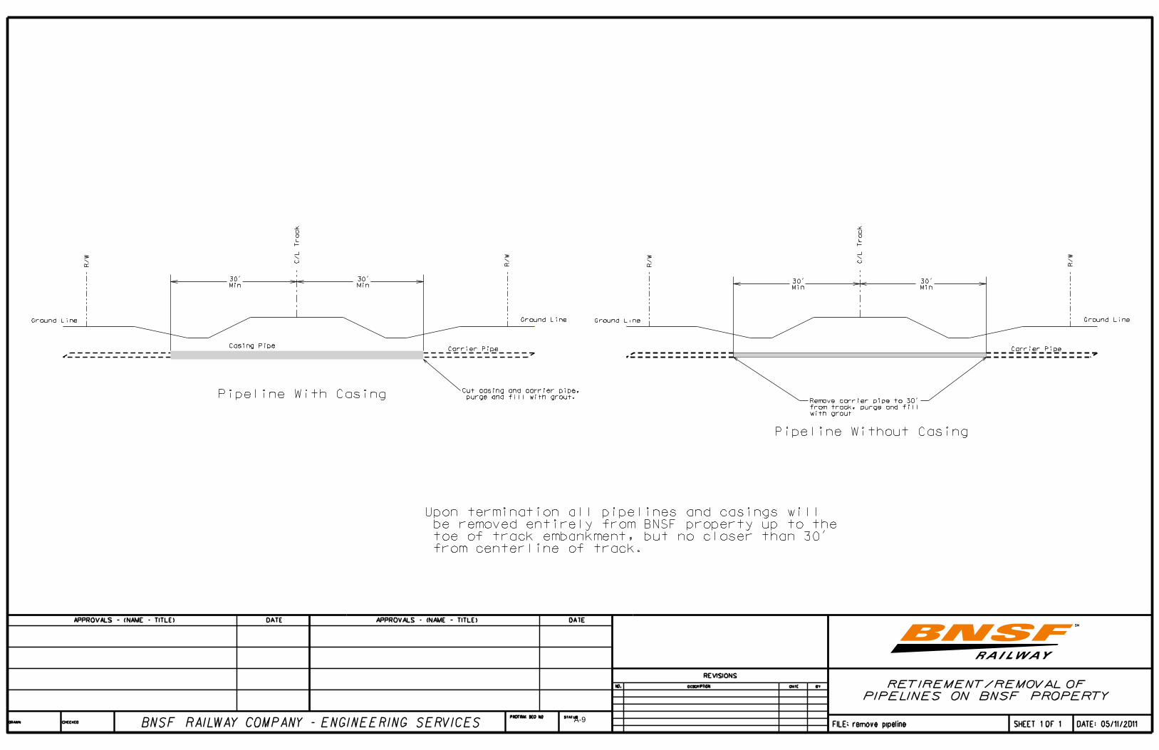
a. Upon termination of license the pipeline needs to be removed from BNSF property except for the portion under the track embankment. For pipelines crossing under the tracks the pipe and casing will be cut just short of the toe of embankment slope, purged and filled with a flowable grout (see appendix page A-9).

************************************
PART 4
PLANS, APPROVALS AND
PROCEDURES
************************************

May 18, 2011 Page 4-2
PART 4 - PLANS, APPROVALS AND PROCEDURES A. Plans and Approvals 1. Design
a. The design of all utility installations will be the responsibility of the Utility Owner.
b. The plans for the proposed installation shall be submitted with the application and have BNSF approval before construction is initiated.
c. Plans shall be drawn to scale showing the relationship of the proposed utility line to the
railroad tracks, the angle of crossing, location of valves and vents, the railroad mile post and engineering station, railroad property lines and general layout of tracks and other railroad facilities. The plans should include a cross-section (or sections) from the field survey that will show utility placement in relation to actual profile of ground and tracks. If tunneling is proposed, method of supporting tracks or driving of tunnel shall be shown. The geotechnical study, when required, should be included.
d. The plans should contain the following data for carrier pipe and casing pipe:
Contents to be carried Inside diameter Pipe material Specifications and grade of material Wall thickness Actual working pressure Type of joints Longitudinal joint factor Coating Method of installation Vents-Number, Size, Height above ground Seals-Both ends, One end Cover (top of tie to top of pipe or casing) Cover (other than under tracks) Cover (at ditches) Cathodic protection Type, Size and Spacing of insulators or supports
e. When a geotechnical study is required, the findings and protection plan shall be prepared by a licensed civil engineer and included with the plans. The geotechnical crew will need to be properly permitted to enter BNSF right-of-way and a BNSF flagman will be required when working within 25 feet of the track.
May 18, 2011 Page 4-3
2. Approvals a. Approval of plans and application forms is required for all installations of utilities prior
to initiation of work on railroad property. b. If surveying is necessary for the completion of an application, a “Right of Entry” or
“Temporary Occupancy Permit” must be executed and referenced. B. License Procedures 1. Submit applications to:
Jones Lang LaSalle 3017 Lou Menk Drive Fort Worth, TX 76131-2800
2. Upon receipt of the application, a letter will be forwarded acknowledging receipt and advising of the Permit & Contract file reference number that has been assigned and the person who should be contacted for further inquiries.
3. Office Hours: 8:00 A.M. to 5:00 P.M. Monday through Friday, CT Phone Number: (toll free) 866-498-6647. Fax: 817-306-8265 4. Agreements will be required for all encroachments on railroad property. 5. Generally, agreement-processing time will be thirty to sixty days. Please allow sufficient
lead-time for document handling prior to desired construction date. Before construction begins, agreements must be executed by Utility Owner and returned. Verbal authorizations will not be granted or permitted. A minimum of seventy-two (72) hours advance notice after execution of an agreement will be required prior to initiation of construction.
6. License fees must be submitted at the time the agreement is executed and returned. 7. Applications are to be made on the standard application form including an Exhibit “A.” C. Construction 1. The execution of the work on railroad property shall be subject to the inspection and
direction of the BNSF Roadmaster or his representative. 2. A representative of BNSF Signal Department must be present during installation if railroad
signals are in the vicinity of the proposed construction.

************************************
APPENDIX
************************************

Date:_______________________
APPLICATION FOR PIPE LINE CROSSING OR LONGITUDINAL Jones Lang LaSalle APPLICANT'S TAX I.D.
NO./SS#________________________ ATTN: Permit Services 3017 Lou Menk Drive Fort Worth, TX 76131-2800 We submit for your approval the following specifications for a pipe line we propose to build across BNSF RAILWAY COMPANY’S right-of-way, as shown on enclosed sketch. IS THIS PROJECT ARRA FUNDED? Yes ____ No ____ Legal name of company/municipality who will own the pipeline:_____________________________________ Is this a condemning authority? Yes ___ No___ State in which Incorporated: ______________ If not incorporated, please attach name of owners or partners. Name of contact for ownership entity: ______________________Telephone: __________ Fax: ___________ Correct Mailing Address: ___________________________________________________Zip Code: ________ Type of Encroachment: Crossing ___ Longitudinal ____ Location of Encroachment: _____1/4 Section ____ Twsp _____Range _____Mile Post ________+_______ Name of nearest town on Railroad: ___________________________ County_________________ State_____Name of nearest roadway crossing: ____________________________ Width of public road or street: _____ ft Within limits of public road or street: Yes ____ No_____ If yes, distance form center line of road: _____ft Contents to be handles through pipe: _____________________ CARRIER CASING Length of pipe on RR property (plastic pipe must be encased full width of R-O-W) _________ft. _________ft. Inside diameter of pipe _________in. _________in. Pipe Material _________ _________ Specification & grade (Minimum yield strength casing 35,000 psi.) _________ _________ Wall Thickness (min. wall thickness of casing pipe under 14 in-0.188 in E-80 Loading) _________ _________ Actual working pressure _________psi _________ Type of Joint (mechanical or welded type) _________ _________ Coating _________ _________ Distance-Base of rail to top of pipe _________ _________ (Flammable, contents, steam, water or non-flammable-min. 5½ ft. under main track) (Uncased, gaseous products-min.10’ under track) Minimum ground cover on Railroad property (minimum 3 feet) _________ _________ Cathodic protection casing- (flammable substance) _________ _________ Type of insulators or support: __________________________ Size _________ Space _________ Number of Vents (flammable substances require 2 vents)_______ Size______ Height above ground _________ Method of Crossing: Jacking ________ Trench ________ Dry Bore Only________ (if trenched-Railroad to furnish flagman at applicant’s expense) (If bored or jacked-Jacking pit location min. 30 feet from centerline of track. Pit must not be open more than 48 hrs. and must be protected when not in use) Does pipeline support oil or gas well? Yes____ No ____ If yes, distance from Railroad property ____ ft. Name of well: ______________________ Is applicant a Railroad Shipper? Yes___ No ___ If yes, BNSF Marketing Rep name and number:_________________________________________________ Was this service requested by BNSF? Yes ___ No ___ If yes, who requested? __________________________ Requestor Telephone Number: ________________ Is this installation in conjunction with a track or track expansion project? Yes ___ No ___ If yes, BNSF contact name and number: ______________________________________________________ Attached to this sheet is location plan and detail sketch. Sketch shows tie-down measurement to centerline of nearest road crossing, bridge or other railroad structure. Please authorize us to proceed with this installation or advise what changes are necessary to meet your specifications. Signed: ___________________________________ Print Name: ___________________________________ Title: ___________________________________ Telephone: _____________________Fax ___________
If you would like confirmation of your application, please print your email address: ____________________________________
If you need additional assistance, please contact Jones Lange LaSalle/Permits Department at 817-230-2626 A-1

Date: _______________________
APPLICATION FOR WIRE LINE CROSSING OR LONGITUDINAL Jones Lang LaSalle TAX I.D. NO./SS# __________________________ 3017 Lou Menk Drive, Suite 100 Fort Worth, TX 76131-2800 ATTN: Permit Services We submit for your approval the following specifications for a wire line we propose to build across BNSF RAILWAY COMPANY’S Right-of-way, as shown on enclosed drawing. Legal name of company/municipality who will own the wireline: __________________________________________ Is this a condemning Authority? Yes___ No___ IS THE PROJECT ARRA FUNDED? Yes ____ No ___ State in which Incorporated: ____________________ If not incorporated, please attach name of owners or partners. Name of contact for ownership entity: ________________________Telephone: ____________ Fax: _____________ Correct Mailing Address: _______________________________________________________ Zip Code: _________ Type of Encroachment: Crossing: ________ Longitudinal: ________ Location of Encroachment: ______1/4 Section ______ Twsp _______ Range ______ Mile Post _______+______ Name of nearest town on Railroad: ______________________________County________________ State_______ Name of nearest roadway crossing: ______________________________Width of public road or street: ________ ft Within limits of public road or street: Yes _____ No______ If yes, distance form center line of road: _________ft Width of public road or street: _____ ft. Kind of encroachment: Electric: __________ Telephone: __________ Other: ___________ No. of wires or cables: __________ Type of wires/cables: ___________ Volts: ______ Phase ______ Cycles_____ No. of conduits: _______________ No. of occupied conduits: ______________ No. of vacant conduits: _________ Length of encroachment: ___________________________ Adjacent spans: _______________ ft. ____________ft. Appurtenances on RR Company property: __________________________________________________________ Wire clearance over or under top of rail: ___________________________ft _____________________________ft. If under track, size and kind of conduit: _____________________________________________________________ Wire clearance over RR Company wire lines: ________________________________________________________ Was this service requested by BNSF? Yes _________ No _________ If yes, by what Railroad representative? ___________________________________ BNSF Contact phone number: __________________________________________ Is applicant a Railroad Shipper? Yes___ No ___ If yes, BNSF Marketing Rep name and number: _____________________________________________ Is this installation in conjunction with a track or track expansion project? Yes ___ No ___ If yes, BNSF contact name and number: ______________________________________________________ Is this installation associated with a public road crossing/widening or grade-separation project? Yes ___ No ___ If yes, please provide details and plans for said crossing/widening/separation project with your application. Attached to this sheet is a pole head diagram (if required) and location plan. Location plan shows tie-down measurement to centerline of nearest road crossing, bridge or other railroad structure. Please authorize us to proceed with construction of this encroachment as proposed or advise what changes are necessary to meet your specifications. I agree that I have read the instructions for installations of wirelines as detailed in the Utility Accommodation Policy.
Signed:
Print Name: Title: Telephone: Fax: Email:
Wireline 02/10
If you would like confirmation of your application, please print your email address: __________________________________________
A-2

Wireline 02/10
POLE HEAD AND DATA SHEET
This completed form to accompany application to construct a wire line on BNSF RAILWAY COMPANY’S right-of-way. Name of Company: _________________________________________________________________________ Location of encroachment: ___________ft. Section: ____________ Twsp: _____________ Range____ _____ Nearest Town: ___________________________________________ County: ___________________________ POLES Kind Size Height Class Set-in Earth-Rock GUY WIRES
Overhead Down Kind Size CROSS ARMS
Material Size X X FRONT ELEVATION INSULATORS
Material Type Size BRACKETS
Material Type Size CONDUCTORS
Material Kind Size LINE CHARACTERISTICS Voltage Phase Cycle SIDE ELEVATION
A-3

Date: ___________________
APPLICATION FOR ENVIRONMENTAL ACCESS PERMIT
Jones Lang LaSalle APPLICANT”S TAX I.D./S.S. # _________________ Attn: Permit Services 3017 Lou Menk Dr., Suite 100 Fort Worth, TX 76131-2800 Name of company/municipality who will occupy the property: ________________________________ Is this a condemning authority? Yes____ No____ Name of contact: _____________________Telephone: ____________ __ Fax: ________________ State in which incorporated: _______ If not incorporated, please attach name(s) of owners or partners. Mailing Address: _______________________________________________ Zip Code: ___________ Name or nearest town on railroad: _________________ ______ County: _______________ State: ____ Railroad Mile Post: ____________ Line Segment: __________ (please complete, if available) Location of proposed occupancy: _____1/4 Sec: _____ Twsp: _____ Range: ______ Is work to be performed within 50 feet of railroad property? Yes ____ No ___ What percentage? _____ How many feet from the track will the work be performed? ____________________________________ Total cost of project: $________________________________________________________________ Area to Occupy: _____________________feet by ________________________feet Date of occupancy (from/to): ___________________________________________________________ Purpose of Testing? (testing for what?): ___________________________________________________ ___________________________________________________________________________________ ___________________________________________________________________________________ ___________________________________________________________________________________ IS THIS PROJECT ARRA FUNDED? Yes ____ No___ Is applicant a Railroad Shipper? Yes___ No ___ If yes, BNSF Marketing Rep name and number: _____________________________________________ Was this service requested by BNSF? Yes ___ No ___ If yes, who requested? __________________________ Requestor Telephone Number: ________________ Is this installation in conjunction with a track or track expansion project? Yes ___ No ___ If yes, BNSF contact name and number: ______________________________________________________ The cost of the Environmental Access permit is $500.00 for sampling purposes and an additional $1000.00 for placement of monitoring wells, due when the permit had been signed by the Permittee and is ready to be returned for execution. Also, Railroad Protective Insurance is required. This insurance will be offered when the Permit draft is sent. APPLICANT IS REQUIRED TO PROVIDE COPY OF PROPOSED WORK PLAN. A $1000.00 deposit may be required and will be returned once BNSF receives copy of the Final Report.
Signed: Print Name: Title: Telephone:
If you would like confirmation of your application,
please print your email address: _________________________________________ A-4

Date: ___01/01/2010_____________
APPLICATION TO CONDUCT SEISMOGRAPH SURVEY Jones Lang LaSalle
3017 Lou Menk Dr., Suite 100 Ft. Worth, TX 76131
ATTN: Permit Services
YOU MUST FIRST HAVE OBTAINED A MINERAL LEASE FROM BNSF PRIOR TO REQUESTING
A SEISMIC PERMIT. IF YOU HAVE NOT OBTAINED THIS LEASE, PLEASE CONTACT:
TERRY YOUNG, FARMERS NATIONAL COMPANY, (918) 895-8020. We submit for your approval the following application for temporary occupancy on BNSF RAILWAY COMPANY right-of-way, as shown on enclosed sketch. IS THIS PROJECT ARRA FUNDED? Yes ____ No ___ Purpose of occupancy ________________________ __________________________________________________________________ Legal name of company or municipality who will occupy the property State in which incorporated If not incorporated, correct name of owners or all partners: Correct mailing address Zip Code Telephone Location of proposed occupancy 1/4 Sec Twsp Rng Railroad Mile Post ________ Name of nearest town on Railroad County State Name of nearest roadway crossing Railroad Days you will actually be on railroad property: _____________________ ___________________ (Date From) (Date To) Total number of cables you will have on railroad property each day ____________ Total length of project: ______________________ _____________________ (Date From) (Date To): Will a crossing under the railroad tracks be required. Yes or No (circle one) If yes at what railroad mile post locations ____________________________________________________________________________________________________________. Attached to this sheet is a location plan and detailed sketch. Shown on the sketch are exact dimensions of the project area and distances to the centerline of nearest railroad track and road crossing, bridge or other railroad structure. I understand that submission of this application does not authorize occupancy of the property. Exact fees and insurance requirements will be forwarded after the application has been reviewed and approved by the Railroad.
Signed: Print Name: Title: Telephone:
If you would like confirmation of your application, please print your email address: __________________________________________
A-5
APPLICANT’S PIPELINE CROSSING CHECKLIST Installation must comply with Standard Specifications. Installation is located at least fifty (50) feet from the end of any railroad bridge or centerline of any culvert. Steel casing must extend completely across railroad property if carrier pipe is made of plastic. Approval for installation may be given if pipeline is uncased and commodity is gaseous and the carrier pipe
is made of steel, buried a minimum of ten (10) feet below base of rail and six (6) feet below ground line for its entire length across railroad property.
A BNSF Signal representative may be present during installation if railroad signals are in vicinity of
installation, unless plans have been approved prior to installation. Applications and Policy are available on-line at: http://www.bnsf.com/communities/faqs/permits-real-estate/
A-6
Copyright BNSF 1999 Revision March 1, 2001
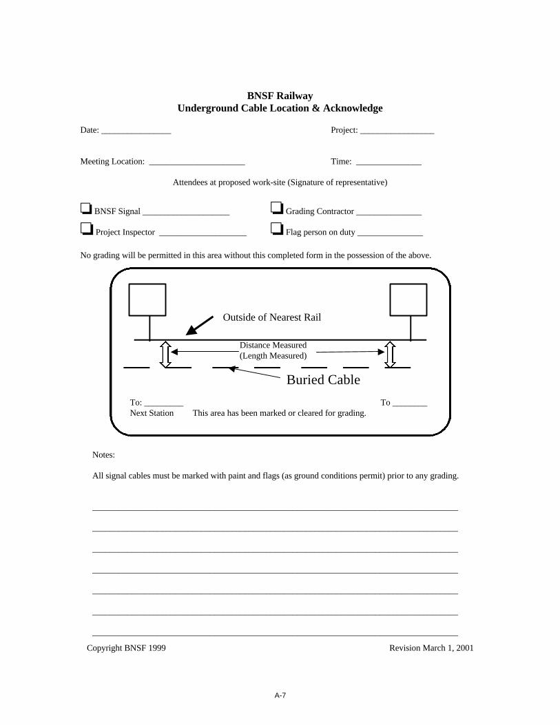
BNSF RailwayUnderground Cable Location & Acknowledge
Date: ________________ Project: _________________
Meeting Location: ______________________ Time: _______________
Attendees at proposed work-site (Signature of representative)
o BNSF Signal ____________________ o Grading Contractor _______________
o Project Inspector ____________________ o Flag person on duty _______________
No grading will be permitted in this area without this completed form in the possession of the above.
Notes:
All signal cables must be marked with paint and flags (as ground conditions permit) prior to any grading.
____________________________________________________________________________________
____________________________________________________________________________________
____________________________________________________________________________________
____________________________________________________________________________________
____________________________________________________________________________________
____________________________________________________________________________________
____________________________________________________________________________________
To: _________ To ________Next Station This area has been marked or cleared for grading.
Outside of Nearest Rail
Distance Measured(Length Measured)
Buried Cable
A-7

D:\Office\Dgn\hdd.dgn 10/16/2008 2:54:47 PM
A-8
A-9

A-10
DEFINITION OF TERMS The terminology used in this Policy strives for conventional meaning and to insure uniform
interpretation. To this end, the following definitions apply: ACCESS CONTROL: Restriction of access to and from abutting lands to railroad property. AREMA: American Railroad Engineering and Maintenance of Way Association. ANSI: American National Standard Institute. ASTM: American Society for Testing and Materials. BACKFILL: Replacement of soil around and over an underground utility facility. BORING: Piercing a hole under the surface of the ground without disturbing the earth surrounding the
hole. Boring may be accomplished by any approved manner. Water jetting or puddling will not be permitted. Holes may be mechanically bored and cased using a cutting head and continuous auger mounted inside of the casing. Small diameter holes may be augured and the casing or utility facility pushed in later.
BNSF: Burlington Northern and Santa Fe Railway Company. BURY: Placement of the utility facility below grade of roadway, ditch or natural ground to a specified
depth. CARRIER: Pipe directly enclosing a transmitted fluid (liquid or gas). CASING: A larger pipe enclosing a carrier. CFR: Code of Federal Regulations. COATING: Material applied to or wrapped around a pipe. COMMUNICATION LINE: Fiber optic, telephone cable and similar lines, not exceeding four hundred
(400) volts to ground or seven hundred fifty (750) volts between any two (2) points of the circuit, the transmittal power of which does not exceed one hundred fifty (150) watts.
CONDUIT OR DUCT: An enclosed tubular runway for protecting wires or cables. COVER: The depth of material placed over a utility. Depth of cover is measured from top of utility casing
or carrier pipe (if no casing is required) to the natural ground line or construction line above the utility. DIRECT BURIAL: Installing a utility underground without encasement, by plowing or trenching. No rail
plows will be permitted. ELECTRIC SUPPLY: Electric light, power supply, and trolley lines, irrespective of voltage used for
transmitting a supply of electrical energy.
A-11

ENCASEMENT: Structural element surrounding a pipe or cable. FLEXIBLE PIPE: A plastic, fiberglass, or metallic pipe having a large ratio of diameter to wall thickness
that can be deformed without undue stress. Copper or aluminum pipe shall be considered as flexible pipe.
GROUNDED: Connected to the earth or to some extended conducting bodies which intentionally or
accidentally is connected with the earth. GROUT: A cement mortar or slurry of fine sand or clay as conditions govern. HORIZONTAL DIRECTIONAL DRILLING: A steerable trenchless method of installing underground
pipes, conduits and cables in a shallow arc along a prescribed bore path by using a surface launched drilling rig, with minimal impact on the surrounding area.
JACK-AND-BORE: The installation method whereby the leading edge of the jacked pipe is well ahead of
the cutting face of the auger bit. The auger is removing waste from inside the pipe as it is being jacked. This method greatly reduces the likelihood of subsidence of granular material during installation.
JACKING: The installation of small pipes by the use of hydraulic jacks or rams to push the pipe under the
traveled surface of a road, railroad roadbed, or other facility. LICENSE: UTILITY LICENSE AGREEMENTS are executed for all utility facilities located on railroad
property. MANHOLE: An opening to an underground utility system which workmen or other may enter for the
purpose of maintaining, inspecting, or making installations. NATURAL GAS PIPELINES: DISTRIBUTION SYSTEM - A pipeline other than a gathering or transmission line. SERVICE LINE - A distribution line that transports gas from a common source of supply to a customer
meter. TRANSMISSION SYSTEM - A pipeline other than a gathering line that transports gas from a
gathering line or storage facility to a distribution center or storage facility. It operates at a hoop stress of twenty percent (20%) or more of the Specified Minimum Yield Strength.
NORMAL: Crossing at a right angle. PERMITS: PERMIT TO BE ON BNSF PROPERTY FOR UTILITY SURVEY is to be executed prior to all
survey work on railroad property. PIPE: A tubular product made as a production item for sale as such. Cylinders formed from plate in the
course of fabrication of auxiliary equipment are not pipes as defined here. PRESSURE: Relative internal pressure in PSI (pounds per square inch) gauge.
A-12

PRIVATE LINES: Any privately owned facilities which convey or transmit the commodities outlined
under the definition for Utilities but are devoted exclusively to private use. PUBLIC LINES: Those facilities which convey or transmit the commodities outlined under the definition
for Utilities and directly or indirectly serve the public or any part thereof. RIGHT OF WAY: A general term denoting land, property of interest therein, usually in a strip, acquired
for or devoted to railroad transportation purposes. SEAL: A material placed between the carrier pipe and casing to prevent the intrusion of water, where ends
of casing are below the ground surface. SHOULDER: That portion of the roadbed outside the ballast. TRENCHED: Installed in a narrow excavation. TUNNELING: Excavating the earth ahead of a large diameter pipe by one or more of the following
processes: 1) The earth ahead of the pipe will be excavated by men using hand tools while the pipe is pushed through the holes by means of jacks, rams or other mechanical devices, 2) The excavation is carried on simultaneously with the installation of tunnel liner plates, and/or 3) The tunnel liner plates are installed immediately behind the excavation as it progresses and are assembled completely away from the inside.
UTILITY OWNER: All privately, publicly or cooperatively owned lines, facilities and systems for
producing, transmitting or distributing communications, power, electricity, light, heat, gas, oil, crude products, water, steam, waste, storm water and other similar commodities, including fire and police signal systems and street lighting systems which directly or indirectly serve the public.
A-13

REFERENCES American National Standards Institute (ANSI) Codes, 1430 Broadway, NY, NY 10018. American Railway Engineering and Maintenance of Way Association (AREMA) Specifications. American Society for Testing and Materials (ASTM) Specifications. American Water Works Association Standards and Specifications, AWWA, 2 Park Avenue, NY, NY 10016. Manual on Uniform Traffic Control Devices - with revisions, US Department of Transportation, Federal
Highway Administration. National Electrical Safety Code, US Department of Commerce, National Bureau of Standards. Pipeline Safety Regulations - Code of Federal Regulations, Tile 49 - Transportation, Parts 191-192-Natural
Gas; Part 195-Liquid Petroleum Gas. Rules and Regulations for Public Water Systems - latest edition, State Health Departments. Rules and Regulations promulgated by the Hazardous Materials Regulation Board of the US Department of
Transportation. Statutory Provisions, 23 U.S.C. 109 and 111.
A-14