Embed Size (px)
Citation preview
UTAH DIVISION OF AIR QUALITY NEW SOURCE PLAN REVIEW Tom Cameron Project fee code: N3031-001 Vice President Summit Vineyard LLC 6682 W. Greenfield Ave West Allis, WI 53214 RE: Approval for Lake Side Power Plant Utah County, CDS A; NA; NSPS, NESHAPS, HAPs, TITLE V
MAJOR, PSD MAJOR, NAA/NSR MAJOR REVIEW ENGINEER: John D. Jenks DATE: October 25, 2004 NOTICE OF INTENT SUBMITTED: May 21, 2004 PLANT CONTACT: Tom Cameron PHONE NUMBER: (414) 475-2015 FAX NUMBER: (414) 475-4552 SOURCE LOCATION: 1825 North Pioneer Lane, Vineyard, UT 84058 Utah County UTM COORDINATES: 4,464.5 km. Northing, 436.0 km. Easting, Zone 12
UTM datum NAD27 N:\Engineer Directory\word\ Company Review
Project - Plan Review October 25, 2004 Page 2
REVIEWS: Peer Engineer ___________________________________________________________
Milka Radulovic DAQ requests that a company/corporation official read the attached draft/proposed Plan Review with Recommended Approval Order Conditions. If this person does not understand or does not agree with the conditions, the PLAN REVIEW ENGINEER should be contacted within five days after receipt of the Plan Review. Special attention needs to be addressed to the Recommended AO Conditions because they will be recommended for the final AO. If this person understands and the company/corporation agrees with the Plan Review or Recommended AO Conditions, this person should sign below and return (can use FAX # 801-536-4099) within 10 days after receipt of the conditions. If the Plan Review Engineer is not contacted within 10 days, the Plan Review Engineer shall assume that the Company/Corporation official agrees with this Plan Review and will process the Plan Review towards final approval. A 30-day public comment period will be required before the Approval Order can be issued.
Thank You
Applicant Contact ______________________________________________________________ (Signature & Date)
Project - Plan Review October 25, 2004 Page 3
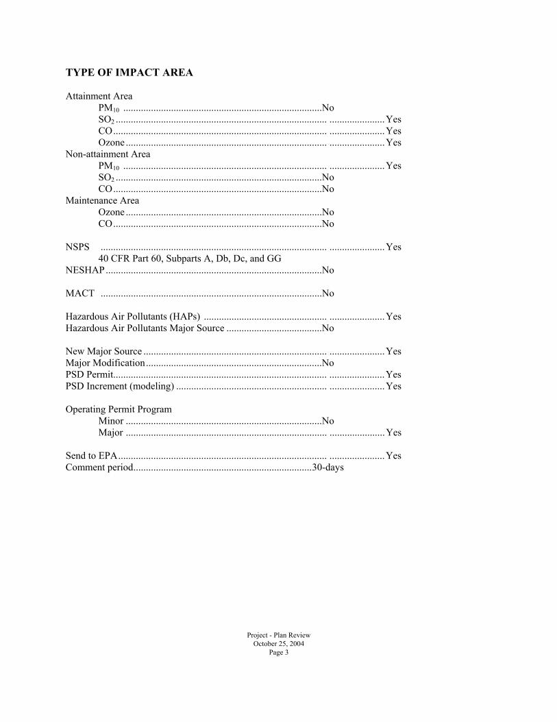
TYPE OF IMPACT AREA
Attainment Area PM10 ...............................................................................No SO2 .................................................................................... ......................Yes CO..................................................................................... ......................Yes Ozone ................................................................................ ......................Yes Non-attainment Area PM10 ................................................................................. ......................Yes SO2 ..................................................................................No CO...................................................................................No Maintenance Area Ozone ..............................................................................No CO...................................................................................No NSPS .......................................................................................... ......................Yes 40 CFR Part 60, Subparts A, Db, Dc, and GG NESHAP......................................................................................No MACT ........................................................................................No Hazardous Air Pollutants (HAPs) ................................................. ......................Yes Hazardous Air Pollutants Major Source ......................................No New Major Source ......................................................................... ......................Yes Major Modification......................................................................No PSD Permit..................................................................................... ......................Yes PSD Increment (modeling) ............................................................ ......................Yes Operating Permit Program Minor ..............................................................................No Major ................................................................................ ......................Yes Send to EPA................................................................................... ......................Yes Comment period.......................................................................30-days
Project - Plan Review October 25, 2004 Page 4
Abstract Summit Vineyard LLC, has submitted a Notice of Intent (NOI) to install and operate a 560 MW (gross) electric generation plant in Utah County. The plant would be located on the site of the old Geneva Steel facility, and would consist of two (2) combustion turbine and HRSG arrangements and a single steam turbine generator. The combustion turbines and HRSG units will be equipped with CO catalysts, SCR, and combustion controls featuring dry-low NOx burners. This source is major under both the Prevention of Significant Deterioration (PSD) and Non-attainment Area New Source Review (NAA/NSR) regulations. Utah County is a Non-attainment area of the National Ambient Air Quality Standards (NAAQS) for PM10. New Source Performance Standards (NSPS) A, Db, Dc, and GG regulations apply to this source. The Acid Rain Program (Title IV) of the Clean Air Act applies to this source. Title V of the 1990 Clean Air Act applies to this source, with the requirement that the source submit a Title V Operating Permit application within one year of beginning operations. The emissions, in tons per year, will be as follows: PM10 95.8, NOx 138.3, SO2 26.5, CO 547.1, VOC 72.8, HAPs (Formaldehyde) 6.2. Newspaper Notice Summit Vineyard LLC, has submitted a Notice of Intent (NOI) to install and operate a 560 MW (gross) electric generation plant in Utah County. New Source Performance Standards (NSPS) A, Db, Dc, and GG regulations apply to this source. The Acid Rain Program (Title IV) of the Clean Air Act applies to this source. Title V of the 1990 Clean Air Act applies to this source, with the requirement that the source submit a Title V Operating Permit application within one year of beginning operations. I. DESCRIPTION OF PROPOSAL Two natural gas-fired combined cycle CTs will be the primary power generating equipment at the Lake Side Power Plant (LSPP). At full operating capacity (including power augmentation capability), the LSPP will have capacity of approximately 560 MW at site average annual ambient temperatures. The LSPP project site is located on property presently owned by the Geneva Steel Corporation. The parcel includes approximately 60 acres, which is more than adequate for the new generation plant, switchyard, and the peripheral buffers. I.1 LOCATION The site is located in the town of Vinyard in Utah County, Utah, approximately 2 miles west of the town of Orem. The project is located on the south side of 200 South Road, between North Pioneer Lane and 250 West (Proctor) Road. The site address is 1825 North Pioneer Lane, Vineyard, UT 84058. The Lake Side Power Plant will be located in an area that is designated as non-attainment for PM10 and
Engineering Review: Summit Vineyard, LLC. Lake Side Power Plant October 25, 2004 Page 5
unclassified/attainment for all other criteria pollutants for state and federal standards. The project site is essentially flat, with an average elevation of approximately 4,500 feet above mean sea level (MSL). I.2 DESCRIPTION OF PLANT PROCESSES The primary processes at this project consist of the following equipment:
• 2 Siemens Westinghouse 501F CTs (165 MW each) • 2 duct-fired HRSGs • 1 steam turbine generator unit (240 MW)
The support processes having the potential for air emissions at this project consist of the following equipment:
• One cooling tower for the steam turbine • Auxiliary boiler • Fuel dew point heater • Fire pump (diesel engine) • Standby diesel generator
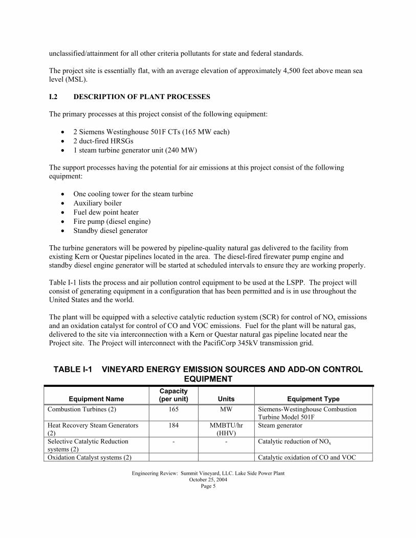
The turbine generators will be powered by pipeline-quality natural gas delivered to the facility from existing Kern or Questar pipelines located in the area. The diesel-fired firewater pump engine and standby diesel engine generator will be started at scheduled intervals to ensure they are working properly. Table I-1 lists the process and air pollution control equipment to be used at the LSPP. The project will consist of generating equipment in a configuration that has been permitted and is in use throughout the United States and the world. The plant will be equipped with a selective catalytic reduction system (SCR) for control of NOx emissions and an oxidation catalyst for control of CO and VOC emissions. Fuel for the plant will be natural gas, delivered to the site via interconnection with a Kern or Questar natural gas pipeline located near the Project site. The Project will interconnect with the PacifiCorp 345kV transmission grid. TABLE I-1 VINEYARD ENERGY EMISSION SOURCES AND ADD-ON CONTROL
EQUIPMENT
Equipment Name Capacity (per unit) Units Equipment Type
Combustion Turbines (2) 165 MW Siemens-Westinghouse Combustion Turbine Model 501F
Heat Recovery Steam Generators (2)
184 MMBTU/hr (HHV)
Steam generator
Selective Catalytic Reduction systems (2)
-
- Catalytic reduction of NOx
Oxidation Catalyst systems (2) Catalytic oxidation of CO and VOC
Engineering Review: Summit Vineyard, LLC. Lake Side Power Plant October 25, 2004 Page 6
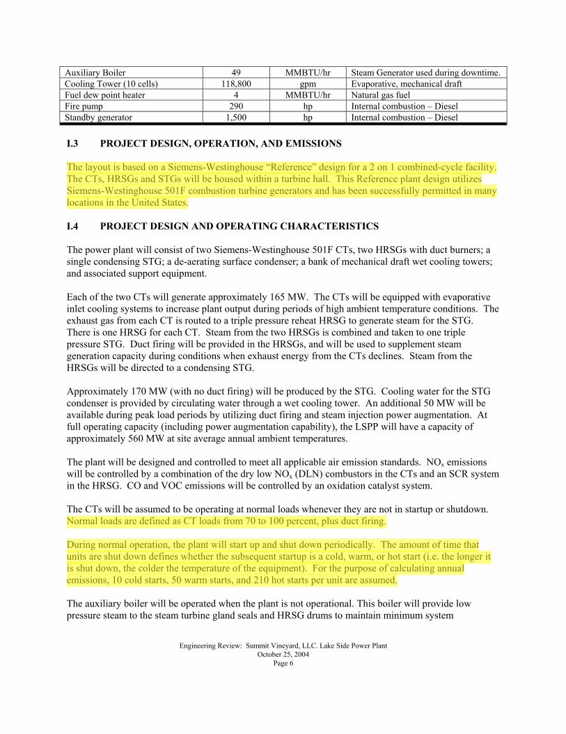
Auxiliary Boiler 49 MMBTU/hr Steam Generator used during downtime. Cooling Tower (10 cells) 118,800 gpm Evaporative, mechanical draft Fuel dew point heater 4 MMBTU/hr Natural gas fuel Fire pump 290 hp Internal combustion � Diesel Standby generator 1,500 hp Internal combustion � Diesel I.3 PROJECT DESIGN, OPERATION, AND EMISSIONS The layout is based on a Siemens-Westinghouse �Reference� design for a 2 on 1 combined-cycle facility. The CTs, HRSGs and STGs will be housed within a turbine hall. This Reference plant design utilizes Siemens-Westinghouse 501F combustion turbine generators and has been successfully permitted in many locations in the United States. I.4 PROJECT DESIGN AND OPERATING CHARACTERISTICS The power plant will consist of two Siemens-Westinghouse 501F CTs, two HRSGs with duct burners; a single condensing STG; a de-aerating surface condenser; a bank of mechanical draft wet cooling towers; and associated support equipment. Each of the two CTs will generate approximately 165 MW. The CTs will be equipped with evaporative inlet cooling systems to increase plant output during periods of high ambient temperature conditions. The exhaust gas from each CT is routed to a triple pressure reheat HRSG to generate steam for the STG. There is one HRSG for each CT. Steam from the two HRSGs is combined and taken to one triple pressure STG. Duct firing will be provided in the HRSGs, and will be used to supplement steam generation capacity during conditions when exhaust energy from the CTs declines. Steam from the HRSGs will be directed to a condensing STG. Approximately 170 MW (with no duct firing) will be produced by the STG. Cooling water for the STG condenser is provided by circulating water through a wet cooling tower. An additional 50 MW will be available during peak load periods by utilizing duct firing and steam injection power augmentation. At full operating capacity (including power augmentation capability), the LSPP will have a capacity of approximately 560 MW at site average annual ambient temperatures. The plant will be designed and controlled to meet all applicable air emission standards. NOx emissions will be controlled by a combination of the dry low NOx (DLN) combustors in the CTs and an SCR system in the HRSG. CO and VOC emissions will be controlled by an oxidation catalyst system. The CTs will be assumed to be operating at normal loads whenever they are not in startup or shutdown. Normal loads are defined as CT loads from 70 to 100 percent, plus duct firing. During normal operation, the plant will start up and shut down periodically. The amount of time that units are shut down defines whether the subsequent startup is a cold, warm, or hot start (i.e. the longer it is shut down, the colder the temperature of the equipment). For the purpose of calculating annual emissions, 10 cold starts, 50 warm starts, and 210 hot starts per unit are assumed. The auxiliary boiler will be operated when the plant is not operational. This boiler will provide low pressure steam to the steam turbine gland seals and HRSG drums to maintain minimum system
Engineering Review: Summit Vineyard, LLC. Lake Side Power Plant October 25, 2004 Page 7
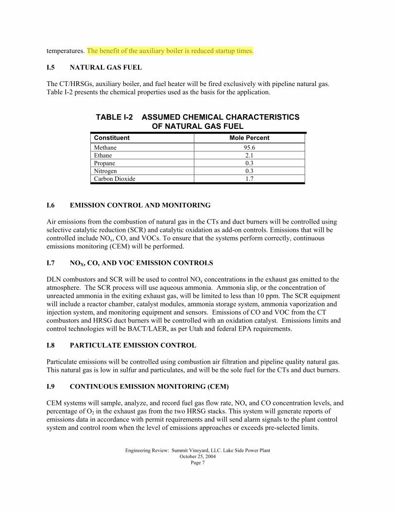
temperatures. The benefit of the auxiliary boiler is reduced startup times. I.5 NATURAL GAS FUEL The CT/HRSGs, auxiliary boiler, and fuel heater will be fired exclusively with pipeline natural gas. Table I-2 presents the chemical properties used as the basis for the application.
TABLE I-2 ASSUMED CHEMICAL CHARACTERISTICS OF NATURAL GAS FUEL
Constituent Mole Percent Methane 95.6 Ethane 2.1 Propane 0.3 Nitrogen 0.3 Carbon Dioxide 1.7
I.6 EMISSION CONTROL AND MONITORING Air emissions from the combustion of natural gas in the CTs and duct burners will be controlled using selective catalytic reduction (SCR) and catalytic oxidation as add-on controls. Emissions that will be controlled include NOx, CO, and VOCs. To ensure that the systems perform correctly, continuous emissions monitoring (CEM) will be performed. I.7 NOX, CO, AND VOC EMISSION CONTROLS DLN combustors and SCR will be used to control NOx concentrations in the exhaust gas emitted to the atmosphere. The SCR process will use aqueous ammonia. Ammonia slip, or the concentration of unreacted ammonia in the exiting exhaust gas, will be limited to less than 10 ppm. The SCR equipment will include a reactor chamber, catalyst modules, ammonia storage system, ammonia vaporization and injection system, and monitoring equipment and sensors. Emissions of CO and VOC from the CT combustors and HRSG duct burners will be controlled with an oxidation catalyst. Emissions limits and control technologies will be BACT/LAER, as per Utah and federal EPA requirements. I.8 PARTICULATE EMISSION CONTROL Particulate emissions will be controlled using combustion air filtration and pipeline quality natural gas. This natural gas is low in sulfur and particulates, and will be the sole fuel for the CTs and duct burners. I.9 CONTINUOUS EMISSION MONITORING (CEM) CEM systems will sample, analyze, and record fuel gas flow rate, NOx and CO concentration levels, and percentage of O2 in the exhaust gas from the two HRSG stacks. This system will generate reports of emissions data in accordance with permit requirements and will send alarm signals to the plant control system and control room when the level of emissions approaches or exceeds pre-selected limits.
Engineering Review: Summit Vineyard, LLC. Lake Side Power Plant October 25, 2004 Page 8
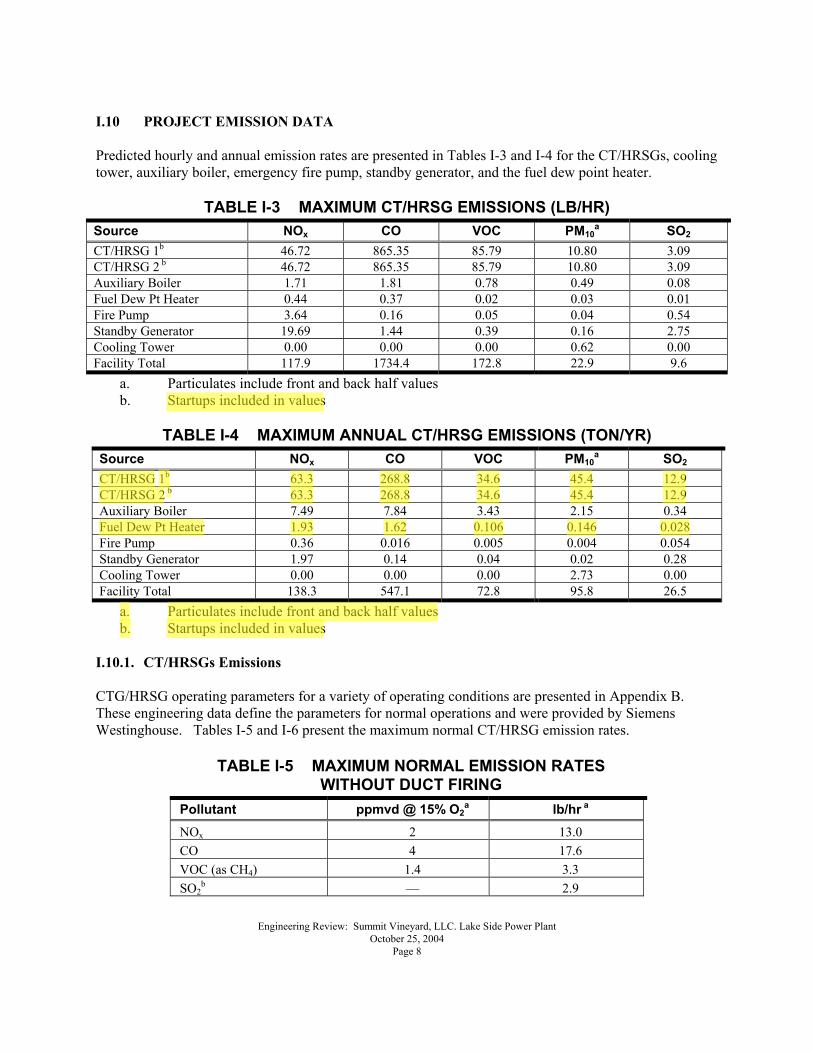
I.10 PROJECT EMISSION DATA Predicted hourly and annual emission rates are presented in Tables I-3 and I-4 for the CT/HRSGs, cooling tower, auxiliary boiler, emergency fire pump, standby generator, and the fuel dew point heater.
TABLE I-3 MAXIMUM CT/HRSG EMISSIONS (LB/HR) Source NOx CO VOC PM10
a SO2 CT/HRSG 1b 46.72 865.35 85.79 10.80 3.09 CT/HRSG 2 b 46.72 865.35 85.79 10.80 3.09 Auxiliary Boiler 1.71 1.81 0.78 0.49 0.08 Fuel Dew Pt Heater 0.44 0.37 0.02 0.03 0.01 Fire Pump 3.64 0.16 0.05 0.04 0.54 Standby Generator 19.69 1.44 0.39 0.16 2.75 Cooling Tower 0.00 0.00 0.00 0.62 0.00 Facility Total 117.9 1734.4 172.8 22.9 9.6
a. Particulates include front and back half values b. Startups included in values
TABLE I-4 MAXIMUM ANNUAL CT/HRSG EMISSIONS (TON/YR)
Source NOx CO VOC PM10a SO2
CT/HRSG 1b 63.3 268.8 34.6 45.4 12.9 CT/HRSG 2 b 63.3 268.8 34.6 45.4 12.9 Auxiliary Boiler 7.49 7.84 3.43 2.15 0.34 Fuel Dew Pt Heater 1.93 1.62 0.106 0.146 0.028 Fire Pump 0.36 0.016 0.005 0.004 0.054 Standby Generator 1.97 0.14 0.04 0.02 0.28 Cooling Tower 0.00 0.00 0.00 2.73 0.00 Facility Total 138.3 547.1 72.8 95.8 26.5
a. Particulates include front and back half values b. Startups included in values
I.10.1. CT/HRSGs Emissions CTG/HRSG operating parameters for a variety of operating conditions are presented in Appendix B. These engineering data define the parameters for normal operations and were provided by Siemens Westinghouse. Tables I-5 and I-6 present the maximum normal CT/HRSG emission rates.
TABLE I-5 MAXIMUM NORMAL EMISSION RATES WITHOUT DUCT FIRING
Pollutant ppmvd @ 15% O2a lb/hr a
NOx 2 13.0 CO 4 17.6 VOC (as CH4) 1.4 3.3 SO2
b � 2.9
Engineering Review: Summit Vineyard, LLC. Lake Side Power Plant October 25, 2004 Page 9
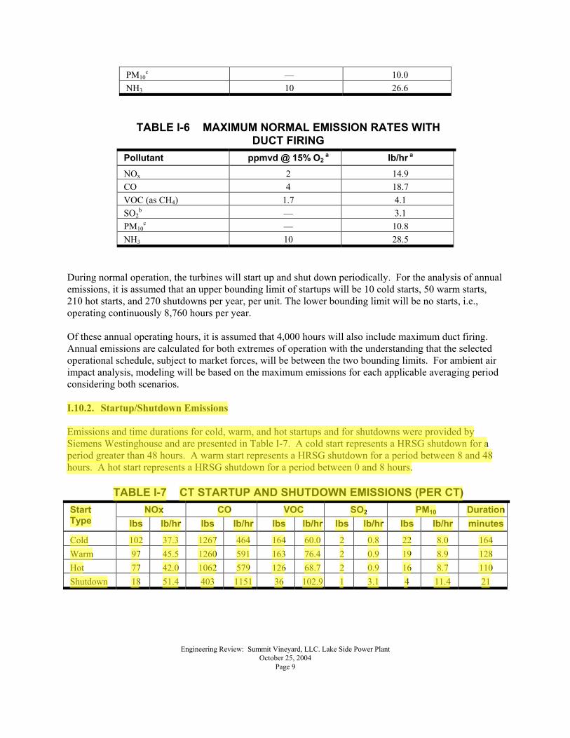
PM10c � 10.0
NH3 10 26.6
TABLE I-6 MAXIMUM NORMAL EMISSION RATES WITH DUCT FIRING
Pollutant ppmvd @ 15% O2 a lb/hr a
NOx 2 14.9 CO 4 18.7 VOC (as CH4) 1.7 4.1 SO2
b � 3.1 PM10
c � 10.8 NH3 10 28.5
During normal operation, the turbines will start up and shut down periodically. For the analysis of annual emissions, it is assumed that an upper bounding limit of startups will be 10 cold starts, 50 warm starts, 210 hot starts, and 270 shutdowns per year, per unit. The lower bounding limit will be no starts, i.e., operating continuously 8,760 hours per year. Of these annual operating hours, it is assumed that 4,000 hours will also include maximum duct firing. Annual emissions are calculated for both extremes of operation with the understanding that the selected operational schedule, subject to market forces, will be between the two bounding limits. For ambient air impact analysis, modeling will be based on the maximum emissions for each applicable averaging period considering both scenarios. I.10.2. Startup/Shutdown Emissions Emissions and time durations for cold, warm, and hot startups and for shutdowns were provided by Siemens Westinghouse and are presented in Table I-7. A cold start represents a HRSG shutdown for a period greater than 48 hours. A warm start represents a HRSG shutdown for a period between 8 and 48 hours. A hot start represents a HRSG shutdown for a period between 0 and 8 hours.
TABLE I-7 CT STARTUP AND SHUTDOWN EMISSIONS (PER CT) NOx CO VOC SO2 PM10 DurationStart
Type lbs lb/hr lbs lb/hr lbs lb/hr lbs lb/hr lbs lb/hr minutes
Cold 102 37.3 1267 464 164 60.0 2 0.8 22 8.0 164 Warm 97 45.5 1260 591 163 76.4 2 0.9 19 8.9 128 Hot 77 42.0 1062 579 126 68.7 2 0.9 16 8.7 110 Shutdown 18 51.4 403 1151 36 102.9 1 3.1 4 11.4 21
Engineering Review: Summit Vineyard, LLC. Lake Side Power Plant October 25, 2004 Page 10
I.10.3. Cooling Tower Emissions A mechanical draft cooling tower is required for the steam condensing portion of the steam turbine cycle. The cooling tower employs water to cool the process water and results in an increase in both the temperature and moisture content of the air passing through it. Entrained liquid droplets in this air, known as �drift,� may be carried out of the tower through the exhaust fan duct. Following evaporation of the water droplets, the dissolved solids present in the drift may be classified as PM emissions. To calculate PM10 emissions, it is assumed that the drift droplet total dissolved solids (TDS) content is the same as the circulating water. As a conservative estimate of TDS, a value of 2,100 milligrams per liter (mg/l or parts per million, or ppm) was used based on a water quality analysis of the ground water supply. This analysis indicated a maximum TDS concentration of 300 mg/l for the makeup water. The circulating water is cycled seven times. This results in a calculated circulating water concentration of 300 mg/l multiplied by seven cycles for a total of 2,100 mg/l. Cooling tower particulate emissions are estimated based on a mass-balance emission calculation. High-efficiency drift eliminators will limit escaping water particles to 0.0005 percent of the circulating water rate. The high-efficiency drift eliminators minimize cooling tower mist and associated PM drift from the cooling tower and represent a significant increase in the control of these emissions over standard mist eliminators. I.10.4. Auxiliary Boiler and Fuel Dew Point Heater A small (49 MMBTU/hr) auxiliary boiler will provide seal steam to the steam turbine and maintain optimal temperature in the HRSG during downtimes. It will operate when the CT/HRSG units are in startup or are not operating. The use of an auxiliary boiler allows for quick startup of the CT/HRSGs. A 3.67 MMBTU/hr fuel dew point heater will treat incoming fuel to keep entrained liquids from condensing as a result of fuel pressure reduction. This heater will be fired with natural gas. This source will operate continuously. I.10.5. Diesel Fire Pump and Standby Generator A diesel-fired 290-horsepower fire pump will be located on the facility for emergency situations. The pump will be tested for a one-hour period once per week and may be operated up to 200 hours per year. A diesel-fired 1490-horsepower standby generator will also be located on the facility to provide power during utility power outages. The generator will be tested for a one-hour period once per week and may be operated up to 200 hours per year. II. EMISSION SUMMARY The emissions from the Lake Side Power Plant will be as follows:
Current Emissions Emission Increases Total Emissions Pollutant tons/year tons/year tons/year
Engineering Review: Summit Vineyard, LLC. Lake Side Power Plant October 25, 2004 Page 11
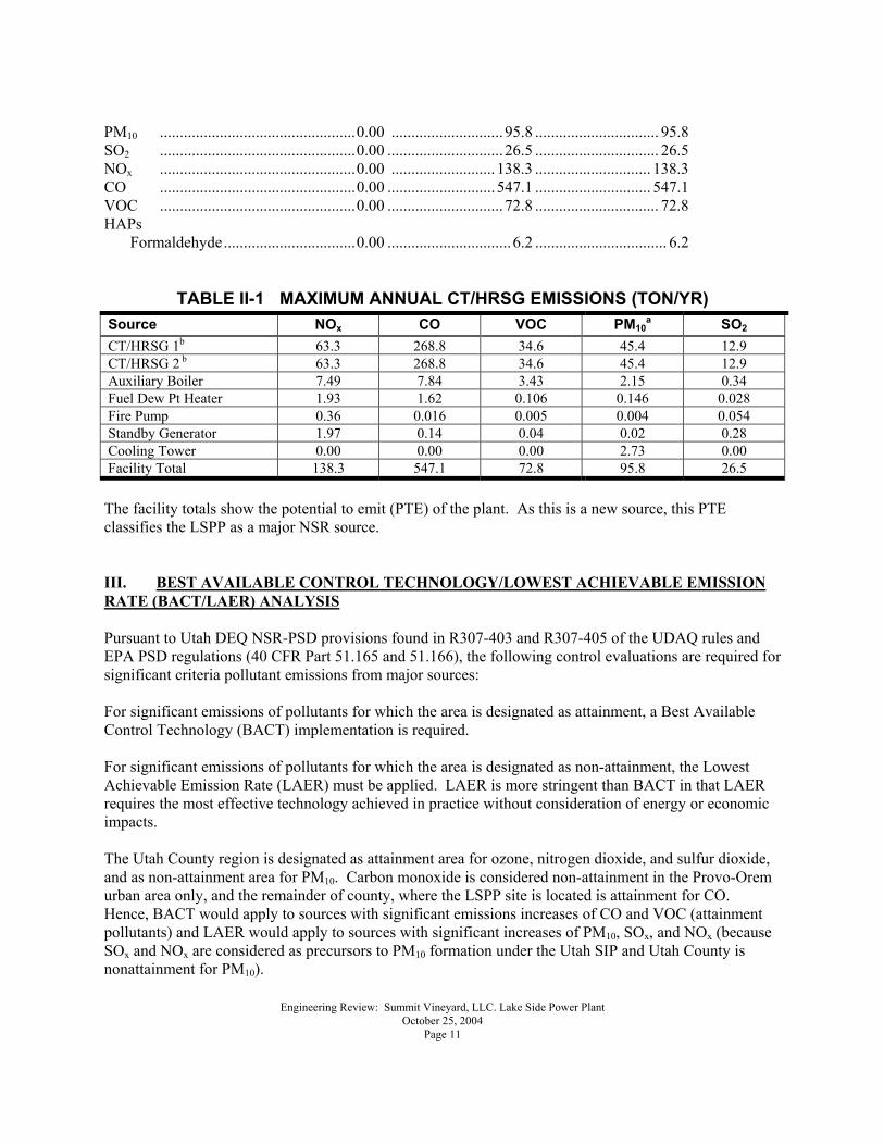
PM10 .................................................0.00 ............................95.8 ............................... 95.8 SO2 .................................................0.00 .............................26.5 ............................... 26.5 NOx .................................................0.00 ..........................138.3 ............................. 138.3 CO .................................................0.00 ...........................547.1 ............................. 547.1 VOC .................................................0.00 .............................72.8 ............................... 72.8 HAPs
Formaldehyde.................................0.00 ...............................6.2 ................................. 6.2
TABLE II-1 MAXIMUM ANNUAL CT/HRSG EMISSIONS (TON/YR) Source NOx CO VOC PM10
a SO2 CT/HRSG 1b 63.3 268.8 34.6 45.4 12.9 CT/HRSG 2 b 63.3 268.8 34.6 45.4 12.9 Auxiliary Boiler 7.49 7.84 3.43 2.15 0.34 Fuel Dew Pt Heater 1.93 1.62 0.106 0.146 0.028 Fire Pump 0.36 0.016 0.005 0.004 0.054 Standby Generator 1.97 0.14 0.04 0.02 0.28 Cooling Tower 0.00 0.00 0.00 2.73 0.00 Facility Total 138.3 547.1 72.8 95.8 26.5 The facility totals show the potential to emit (PTE) of the plant. As this is a new source, this PTE classifies the LSPP as a major NSR source. III. BEST AVAILABLE CONTROL TECHNOLOGY/LOWEST ACHIEVABLE EMISSION RATE (BACT/LAER) ANALYSIS Pursuant to Utah DEQ NSR-PSD provisions found in R307-403 and R307-405 of the UDAQ rules and EPA PSD regulations (40 CFR Part 51.165 and 51.166), the following control evaluations are required for significant criteria pollutant emissions from major sources: For significant emissions of pollutants for which the area is designated as attainment, a Best Available Control Technology (BACT) implementation is required. For significant emissions of pollutants for which the area is designated as non-attainment, the Lowest Achievable Emission Rate (LAER) must be applied. LAER is more stringent than BACT in that LAER requires the most effective technology achieved in practice without consideration of energy or economic impacts. The Utah County region is designated as attainment area for ozone, nitrogen dioxide, and sulfur dioxide, and as non-attainment area for PM10. Carbon monoxide is considered non-attainment in the Provo-Orem urban area only, and the remainder of county, where the LSPP site is located is attainment for CO. Hence, BACT would apply to sources with significant emissions increases of CO and VOC (attainment pollutants) and LAER would apply to sources with significant increases of PM10, SOx, and NOx (because SOx and NOx are considered as precursors to PM10 formation under the Utah SIP and Utah County is nonattainment for PM10).
Engineering Review: Summit Vineyard, LLC. Lake Side Power Plant October 25, 2004 Page 12
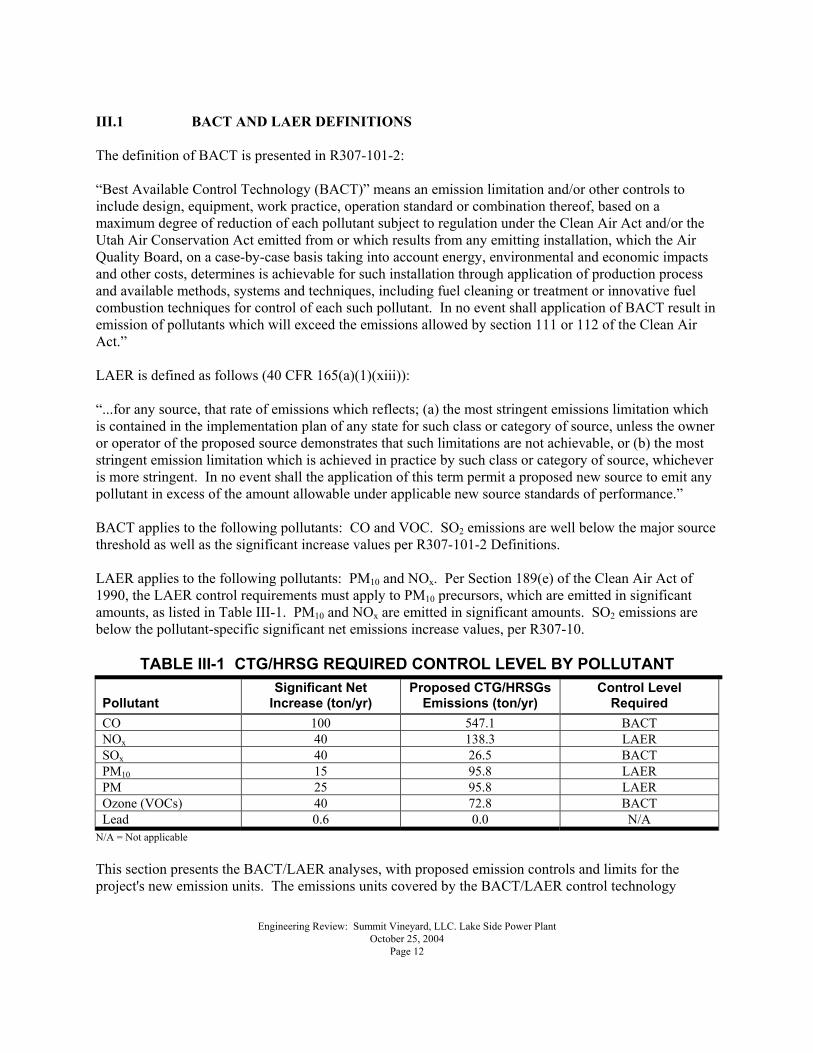
III.1 BACT AND LAER DEFINITIONS The definition of BACT is presented in R307-101-2: �Best Available Control Technology (BACT)� means an emission limitation and/or other controls to include design, equipment, work practice, operation standard or combination thereof, based on a maximum degree of reduction of each pollutant subject to regulation under the Clean Air Act and/or the Utah Air Conservation Act emitted from or which results from any emitting installation, which the Air Quality Board, on a case-by-case basis taking into account energy, environmental and economic impacts and other costs, determines is achievable for such installation through application of production process and available methods, systems and techniques, including fuel cleaning or treatment or innovative fuel combustion techniques for control of each such pollutant. In no event shall application of BACT result in emission of pollutants which will exceed the emissions allowed by section 111 or 112 of the Clean Air Act.� LAER is defined as follows (40 CFR 165(a)(1)(xiii)): �...for any source, that rate of emissions which reflects; (a) the most stringent emissions limitation which is contained in the implementation plan of any state for such class or category of source, unless the owner or operator of the proposed source demonstrates that such limitations are not achievable, or (b) the most stringent emission limitation which is achieved in practice by such class or category of source, whichever is more stringent. In no event shall the application of this term permit a proposed new source to emit any pollutant in excess of the amount allowable under applicable new source standards of performance.� BACT applies to the following pollutants: CO and VOC. SO2 emissions are well below the major source threshold as well as the significant increase values per R307-101-2 Definitions. LAER applies to the following pollutants: PM10 and NOx. Per Section 189(e) of the Clean Air Act of 1990, the LAER control requirements must apply to PM10 precursors, which are emitted in significant amounts, as listed in Table III-1. PM10 and NOx are emitted in significant amounts. SO2 emissions are below the pollutant-specific significant net emissions increase values, per R307-10.
TABLE III-1 CTG/HRSG REQUIRED CONTROL LEVEL BY POLLUTANT
Pollutant Significant Net
Increase (ton/yr) Proposed CTG/HRSGs
Emissions (ton/yr) Control Level
Required CO 100 547.1 BACT NOx 40 138.3 LAER SOx 40 26.5 BACT PM10 15 95.8 LAER PM 25 95.8 LAER Ozone (VOCs) 40 72.8 BACT Lead 0.6 0.0 N/A
N/A = Not applicable This section presents the BACT/LAER analyses, with proposed emission controls and limits for the project's new emission units. The emissions units covered by the BACT/LAER control technology
Engineering Review: Summit Vineyard, LLC. Lake Side Power Plant October 25, 2004 Page 13
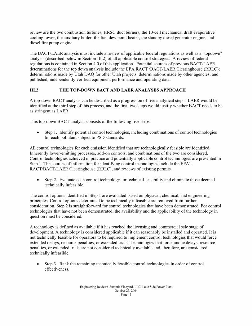
review are the two combustion turbines, HRSG duct burners, the 10-cell mechanical draft evaporative cooling tower, the auxiliary boiler, the fuel dew point heater, the standby diesel generator engine, and diesel fire pump engine. The BACT/LAER analysis must include a review of applicable federal regulations as well as a "topdown" analysis (described below in Section III.2) of all applicable control strategies. A review of federal regulations is contained in Section 4.0 of this application. Potential sources of previous BACT/LAER determinations for the top down analysis include the EPA RACT /BACT/LAER Clearinghouse (RBLC); determinations made by Utah DAQ for other Utah projects, determinations made by other agencies; and published, independently verified equipment performance and operating data. III.2 THE TOP-DOWN BACT AND LAER ANALYSES APPROACH A top-down BACT analysis can be described as a progression of five analytical steps. LAER would be identified at the third step of this process, and the final two steps would justify whether BACT needs to be as stringent as LAER. This top-down BACT analysis consists of the following five steps:
• Step 1. Identify potential control technologies, including combinations of control technologies for each pollutant subject to PSD standards.
All control technologies for each emission identified that are technologically feasible are identified. Inherently lower-emitting processes, add-on controls, and combinations of the two are considered. Control technologies achieved in practice and potentially applicable control technologies are presented in Step 1. The sources of information for identifying control technologies include the EPA�s RACT/BACT/LAER Clearinghouse (RBLC), and reviews of existing permits.
• Step 2. Evaluate each control technology for technical feasibility and eliminate those deemed technically infeasible.
The control options identified in Step 1 are evaluated based on physical, chemical, and engineering principles. Control options determined to be technically infeasible are removed from further consideration. Step 2 is straightforward for control technologies that have been demonstrated. For control technologies that have not been demonstrated, the availability and the applicability of the technology in question must be considered. A technology is defined as available if it has reached the licensing and commercial sale stage of development. A technology is considered applicable if it can reasonably be installed and operated. It is not technically feasible for operators to be required to implement control technologies that would force extended delays, resource penalties, or extended trials. Technologies that force undue delays, resource penalties, or extended trials are not considered technically available and, therefore, are considered technically infeasible.
• Step 3. Rank the remaining technically feasible control technologies in order of control effectiveness.
Engineering Review: Summit Vineyard, LLC. Lake Side Power Plant October 25, 2004 Page 14
The control technologies remaining after Step 2 is complete are ranked in order of control effectiveness. LAER would be the top ranked control technology. LAER is defined as �the most stringent emissions limitation achieved in practice by any such class or category of stationary sources.� This is the step where LAER is selected.
• Step 4. Assume the highest-ranking and technically feasible control represents BACT, unless it can be shown to result in adverse environmental, energy, or economic impacts.
If the top candidate is determined to be less satisfactory than controls that rank below it, the rationale for this conclusion is presented as public record. A thorough documentation of the source-specific environmental, energy, or economic impact must be presented that demonstrates how alternate technologies are appropriate as BACT for a top-listed control technology to be deferred for a lower-listed technology.
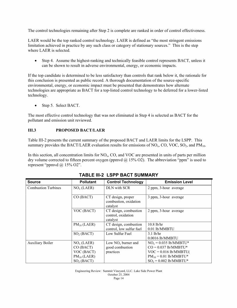
• Step 5. Select BACT. The most effective control technology that was not eliminated in Step 4 is selected as BACT for the pollutant and emission unit reviewed. III.3 PROPOSED BACT/LAER Table III-2 presents the current summary of the proposed BACT and LAER limits for the LSPP. This summary provides the BACT/LAER evaluation results for emissions of NOx, CO, VOC, SO2, and PM10. In this section, all concentration limits for NOx, CO, and VOC are presented in units of parts per million dry volume corrected to fifteen percent oxygen (ppmvd @ 15% O2). The abbreviation �ppm� is used to represent �ppmvd @ 15% O2�.
TABLE III-2 LSPP BACT SUMMARY Source Pollutant Control Technology Emission Level
NOx (LAER) DLN with SCR 2 ppm, 3-hour average
CO (BACT) CT design, proper combustion, oxidation catalyst
3 ppm, 3-hour average
VOC (BACT) CT design, combustion control, oxidation catalyst
2 ppm, 3-hour average
PM10 (LAER) CT design, combustion control, low sulfur fuel
10.8 lb/hr 0.01 lb/MMBTU
Combustion Turbines
SO2 (BACT) Low Sulfur Fuel 3.1 lb/hr 0.0016 lb/MMBTU
Auxiliary Boiler NOx (LAER) CO (BACT) VOC (BACT) PM10 (LAER) SO2 (BACT)
Low NOx burner and good combustion practices
NOx = 0.035 lb/MMBTU* CO = 0.037 lb/MMBTU* VOC = 0.016 lb/MMBTU( PM10 = 0.01 lb/MMBTU* SO2 = 0.002 lb/MMBTU*
Engineering Review: Summit Vineyard, LLC. Lake Side Power Plant October 25, 2004 Page 15
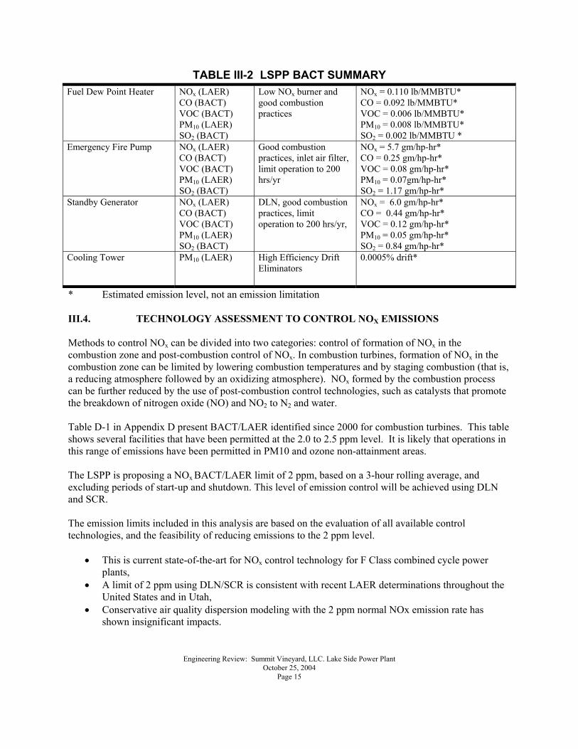
TABLE III-2 LSPP BACT SUMMARY Fuel Dew Point Heater NOx (LAER)
CO (BACT) VOC (BACT) PM10 (LAER) SO2 (BACT)
Low NOx burner and good combustion practices
NOx = 0.110 lb/MMBTU* CO = 0.092 lb/MMBTU* VOC = 0.006 lb/MMBTU* PM10 = 0.008 lb/MMBTU* SO2 = 0.002 lb/MMBTU *
Emergency Fire Pump NOx (LAER) CO (BACT) VOC (BACT) PM10 (LAER) SO2 (BACT)
Good combustion practices, inlet air filter, limit operation to 200 hrs/yr
NOx = 5.7 gm/hp-hr* CO = 0.25 gm/hp-hr* VOC = 0.08 gm/hp-hr* PM10 = 0.07gm/hp-hr* SO2 = 1.17 gm/hp-hr*
Standby Generator NOx (LAER) CO (BACT) VOC (BACT) PM10 (LAER) SO2 (BACT)
DLN, good combustion practices, limit operation to 200 hrs/yr,
NOx = 6.0 gm/hp-hr* CO = 0.44 gm/hp-hr* VOC = 0.12 gm/hp-hr* PM10 = 0.05 gm/hp-hr* SO2 = 0.84 gm/hp-hr*
Cooling Tower PM10 (LAER) High Efficiency Drift Eliminators
0.0005% drift*
* Estimated emission level, not an emission limitation III.4. TECHNOLOGY ASSESSMENT TO CONTROL NOX EMISSIONS Methods to control NOx can be divided into two categories: control of formation of NOx in the combustion zone and post-combustion control of NOx. In combustion turbines, formation of NOx in the combustion zone can be limited by lowering combustion temperatures and by staging combustion (that is, a reducing atmosphere followed by an oxidizing atmosphere). NOx formed by the combustion process can be further reduced by the use of post-combustion control technologies, such as catalysts that promote the breakdown of nitrogen oxide (NO) and NO2 to N2 and water. Table D-1 in Appendix D present BACT/LAER identified since 2000 for combustion turbines. This table shows several facilities that have been permitted at the 2.0 to 2.5 ppm level. It is likely that operations in this range of emissions have been permitted in PM10 and ozone non-attainment areas. The LSPP is proposing a NOx BACT/LAER limit of 2 ppm, based on a 3-hour rolling average, and excluding periods of start-up and shutdown. This level of emission control will be achieved using DLN and SCR. The emission limits included in this analysis are based on the evaluation of all available control technologies, and the feasibility of reducing emissions to the 2 ppm level.
• This is current state-of-the-art for NOx control technology for F Class combined cycle power plants,
• A limit of 2 ppm using DLN/SCR is consistent with recent LAER determinations throughout the United States and in Utah,
• Conservative air quality dispersion modeling with the 2 ppm normal NOx emission rate has shown insignificant impacts.
Engineering Review: Summit Vineyard, LLC. Lake Side Power Plant October 25, 2004 Page 16
III.4.1. Step 1. Identify All Technologies to Control Emissions of NOx The following NOx control technologies were evaluated for their technical feasibility.
• DLN combined with Selective Catalytic Reduction DLN/SCR • EMx (formerly SCONOx) • Xonon • DLN Combustion • Flue Gas Recirculation (FGR) • Selective Non-Catalytic Reduction (SNCR) • Water Steam Injection
III.4.1.1. DLN with SCR The combination of DLN controls followed by SCR is the most stringent control technology that is currently commercially available and achieved in practice for F Class turbines. SCR is a post combustion gas treatment technique used for reducing NO and NO2 to molecular N2 and water in the turbine exhaust stream. Aqueous ammonia (NH3) is typically used as the reducing agent. The basic reactions are: 4NH3 + 4NO + O2 → 4N2 + 6H2O 8NH3 + 6NO2 → 7N2 + 12H2O The reactions take place on the surface of a catalyst. The function of the catalyst is to effectively lower the activation energy of the NOx decomposition reaction. Technical factors related to this technology include the design of the catalyst, optimum operating temperature, sulfur content of the fuel, and design of the NH3 injection system. An SCR system is composed of an aqueous ammonia storage tank, forwarding pumps, and controls; an injection grid (a system of nozzles that spray aqueous ammonia into the exhaust gas ductwork); a reactor that contains the catalyst; and instrumentation and electronic controls. An injection grid disperses NH3 in the flue gas upstream of the catalyst and NH3 and NOx are reduced to N2 and water in the catalyst reactor. This control technique reduces both thermal and fuel NOx in the exhaust streams. The performance and effectiveness of SCR systems directly depend on the temperature of the flue gas when it passes through the catalyst. The optimum temperature range for flue gas in SCR operation, using a conventional vanadium/titanium catalyst, is 600 to 750 °F. For combined cycle units, this temperature window occurs at an intermediate point in the HRSG. DLN combined with SCR is a proven and feasible NOx control technology on F Class combined cycle systems. This system has been demonstrated on similar power plants over the last five years. DLN/SCR is considered a technically feasible alternative to control NOx emissions to 2 ppm. III.4.1.2. EMx EMx (previously referred to as SCONOx) is a post combustion control system produced by EmeraChem,
Engineering Review: Summit Vineyard, LLC. Lake Side Power Plant October 25, 2004 Page 17
LLC. A demonstration project is currently operating at the Federal Plant owned by Sunlaw Cogeneration Partners. This plant uses a GE LM2500 combined cycle power plant with a nominal capacity of 34 MW which is roughly one fifth the capacity of each of the proposed LSPP CT/HRSG units. The GE LM2500 is the largest CT that has been used to demonstrate this control technology at this time. The EMx system uses a coated oxidation catalyst installed in the flue gas to remove both NOx and CO without a reagent such as ammonia. The emissions of NOx are oxidized to NO2 and then absorbed onto the catalyst. A dilute hydrogen gas is passed through the catalyst periodically. This gas desorbs the NO2 from the catalyst and reduces it to N2 before it exits the stack. CO is oxidized to CO2. VOCs are also oxidized by this control technology. EMx operates in a temperature range between 300° F and 700° F. The catalyst uses a potassium carbonate coating that reacts to form potassium nitrates and nitrites on the surface of the catalyst. When all of the carbonate coating on the surface of the catalyst has reacted to form nitrogen compounds, NO2 is no longer absorbed, and the catalyst must be regenerated. Dampers are used to isolate a portion of the catalyst for regeneration. The regenerative gas is passed through the isolated portion of the catalyst while the remaining catalyst stays in contact with the flue gas. After the isolated portion has been regenerated, the next set of dampers closes to isolate and regenerate the next portion of the catalyst. This cycle repeats continuously. As a result, each section of the catalyst is regenerated about once every 15 minutes. Current emissions data (December 1996 through August 2000) show that the Federal Plant is controlling NOx emissions to 1.3 ppm and CO to 1 ppm on a periodic basis for a LM2500 application (excluding start up, shutdown, and frequent maintenance). III.4.1.3. Xonon The Xonon combustion system, developed by Catalytica, improves the combustion process by lowering the peak combustion temperature to reduce the formation of NOx, while further controlling CO and VOC emissions. Most emission control technologies for CTs remove contaminants from exhaust gas before they are released to the atmosphere. In contrast, the overall process in the Xonon system involves partial combustion of the fuel in the catalyst module followed by complete combustion downstream of the catalyst. In the catalyst module, a portion of the fuel is combusted without a flame (thus, at relatively low temperatures and lowered NOx formation). A homogeneous combustion region is located immediately downstream where the remainder of the fuel is combusted. The key feature of the Xonon combustion system is a proprietary catalytic component, called the Xonon Module, which is integral to the CT combustor. Xonon combusts the fuel without a flame, thus eliminating the peak flame temperatures that lead to formation of NOx. Because it prevents the formation of NOx rather than cleaning up NOx after it is produced, no expensive add-on recovery systems are required. The Xonon combustion system consists of four sections:
• The preburner for start-up, acceleration of the CT, and adjustment of the catalyst inlet temperature, if required.
• The fuel injection and fuel-air mixing system that achieves a uniform fuel-air mixture to the
Engineering Review: Summit Vineyard, LLC. Lake Side Power Plant October 25, 2004 Page 18
catalyst. • The Xonon flameless catalyst module, where a portion of the fuel is combusted in a flameless
reaction without creating NOx because the temperature remains below the level where NOx will form.
• The remainder of the fuel is combusted in the burnout zone and CO and unburned hydrocarbons are burned out. This process also is flameless.
Xonon is an innovative technology that is currently being commercialized on small scale projects with support from the U.S. Department of Energy, the California Energy Commission (CEC), and the California Air Resources Board (CARB). CARB has reported on the pilot effort under way in Santa Clara where the Xonon system is operating at a 1.5 MW simple cycle pilot facility. The CARB indicated in its June 1999 Stationary Source Division Report Guidance for Power Plant Siting and Best Available Control Technology (CARB 1999), page 23: �Emission levels from 1.33 to 4.04 ppmvd NOx, at 15 percent oxygen (O2) have been achieved at Silicon Valley Power utilizing the Xonon technology�. But CARB further indicates, �There is not sufficient operating experience to ensure reliable performance on large gas turbines.� III.4.1.4. DLN Combustion Virtually all gas turbine manufacturers are continuing to research and improve on advanced combustion technologies, because they represent the most cost effective approach to NOx reduction for some turbines. With natural gas combustion, control of NOx through design of the combustor is attractive because thermal formation of NOx is the primary mechanism for NOx formation. The thermal NOx reaction converts atmospheric N2 and O2 to NOx at the high temperatures of combustion. DLN combustion results in NOx emission rates of 9 to 25 ppm. With DLN, the W501F can control NOx emissions within the range of 15 to 25 ppm. III.4.1.5. FGR FGR is the process of rerouting exhaust gases into the combustion zone. This results in lowering the combustion zone temperature and oxygen concentrations thus lowering the formation of NOx. III.4.1.6. SNCR The selective non-catalytic reduction (SNCR) process injects ammonia or urea into the exhaust steam. The ammonia or urea reacts with the NO in a series of reactions that reduce the NO to N2. To be effective, this reaction must take place within a narrow range of high temperatures (1,500° F � 2,000° F). At temperatures below this range there is increased ammonia slip, and at temperatures above this range the ammonia or urea can be oxidized to form NO. III.4.1.7. Water or Steam Injection Like FGR, water or steam injection technology results in lowering the combustion zone temperature an oxygen concentrations thus lowering the formation of NOx. III.4.2. Step 2. Eliminate Technically Infeasible Options to Control NOx
Engineering Review: Summit Vineyard, LLC. Lake Side Power Plant October 25, 2004 Page 19
The following technologies have been determined to be technically infeasible to control NOx emissions to levels that would qualify as BACT/LAER:
• Water or Steam Injection • SNCR • FGR • Xonon • EMx
The discussions below summarize this evaluation of the technologies. III.4.2.1. Water or Steam Injection Water or steam injection cannot reduce concentrations of NOx to the levels that would qualify as BACT. Therefore, water steam injection is not an effective control technology for the proposed LSPP turbines and is eliminated as a technically feasible alternative. III.4.2.2. SNCR A review of EPA�s RBLC database, and of EPA�s National Combustion Turbine Spreadsheet has shown that SNCR has never been demonstrated on a combined cycle system. The temperature range required for effective operation of this technology is above the peak temperature for combined cycle systems. The maximum CT exhaust temperature would be approximately 1,200° F. Therefore, SNCR is an infeasible control technology for the LSPP. III.4.2.3. FGR There is no documentation of FGR being used on combined cycle CTs. Therefore, it has been determined that this technology is not feasible. The RBLC database and EPA�s spreadsheet show that flue gas recirculation has never been demonstrated on combined cycle CTs. Therefore, this technology is not considered feasible for the LSPP. III.4.2.4. Xonon The basic research and development of the Xonon combustion system has been completed, and the technology has been confirmed with tests performed on a 1.5 MW turbine at the Silicon Valley Power facility in Santa Clara, California. To date, this technology has not been demonstrated on larger turbines, such as the SW501F. Because the technology has not been demonstrated in practice it does not currently represent BACT. Xonon is an emerging technology and is not commercially available at this time for CTs of the size proposed for this project (F Class CTs). In addition, Xonon has not demonstrated feasibility for long-term operations. Current results for this technology involve limited operations of up to 8,100 hours (reflecting equivalent operations of less than one year) and has been limited to systems with smaller CTs. Therefore, the Xonon catalytic system was rejected because it has not been shown to be technically feasible for F Class CTs or long term operation.
Engineering Review: Summit Vineyard, LLC. Lake Side Power Plant October 25, 2004 Page 20
III.4.2.5. EMx Although EMx technology represents a significant potential advancement in the future of NOx control, it has not been demonstrated in combustion turbines equivalent to the units proposed for the LSPP Project. Recently, Redding Power in California selected EMx as the emission control technology for use on an Alstom GTX 100 with a nominal rating of 43 MW with a 13 MW HRSG. This plant began operation in June 2002. Therefore, there is little data on the long-term viability of this system. Additionally, because of its smaller capacity, the Alstom GTX 100 does not demonstrate the feasibility of EMx for larger turbine systems. EMx has been demonstrated in operations with small CTs, and has been considered for F Class CTs. However, there are no operational data at this time that demonstrate that this technology is feasible for an F Class CT. EMx has never been installed or operated on an F Class CT for either combined or simple cycle operations. In the EMx system, a system of multiple dampers create seals for the sections of catalyst that are regenerating, and the exhaust flow is directed to the active sections of catalyst. If the dampers do not seal, the catalyst within this section will not regenerate and the effectiveness of this section�s emissions control will deteriorate. To resolve this problem it may be necessary to shutdown the power generation system. For the smaller units where EMx is employed the dampers are less than 15 feet in length. The LSPP F Class CTs would be much larger than the CTs where EMx is currently being demonstrated. The width of the proposed LSPP HRSGs would be approximately 45 feet. Also, EMx is currently operating in HRSGs that contain only one module, but the width of the HRSGs associated with F Class CTs would require at least two modules or, possibly, three modules. Because of the larger area required for the exhaust flow, this would present an even greater problem in sealing the dampers and making catalyst regeneration reliable. In addition, the height of the LSPP HRSGs would be approximately 82 feet, and EMx has only been used in units with heights less than 70 feet. Therefore the LSPP HRSGs would require a greater number of dampers, and, consequently, more potential for damper failure. III.4.3. Step 3. Rank Remaining Technologies � Select LAER The remaining technologies are ranked from most feasible to least feasible for achieving NOx emission levels that would qualify as BACT/LAER:
• DLN combined with SCR is the only feasible technology with a long-term record of performance on F Class CT technology.
• EMx has no proven feasibility on F Class CT technology. USEPA Region 9 and the California South Coast Air Quality Management District (SCAQMD) have determined that a NOx emission limit of 2 ppm has been demonstrated in practice for F Class combined cycle projects. Because this is the most stringent limit that has been demonstrated in practice, this represents LAER and would be applied to projects in non-attainment areas (the South Coast Air Basin is an extreme non-attainment area for ozone).
Engineering Review: Summit Vineyard, LLC. Lake Side Power Plant October 25, 2004 Page 21
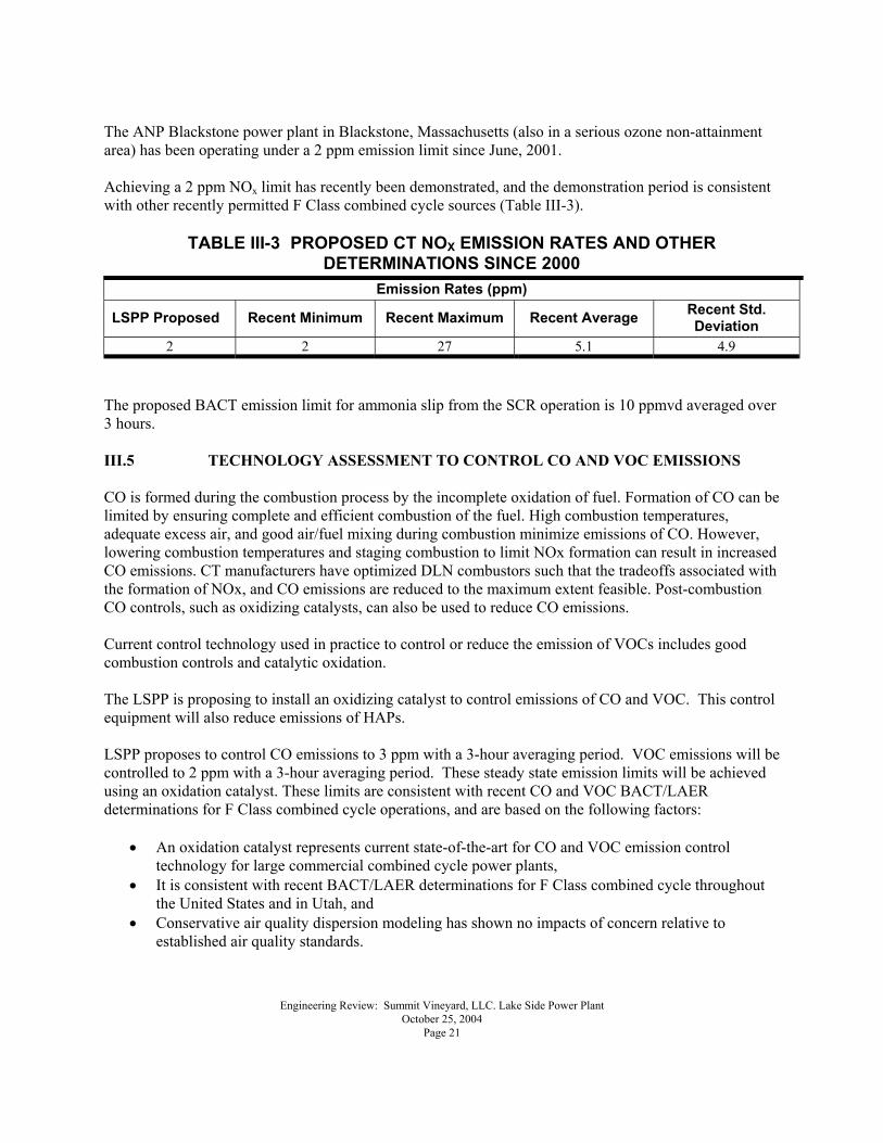
The ANP Blackstone power plant in Blackstone, Massachusetts (also in a serious ozone non-attainment area) has been operating under a 2 ppm emission limit since June, 2001. Achieving a 2 ppm NOx limit has recently been demonstrated, and the demonstration period is consistent with other recently permitted F Class combined cycle sources (Table III-3).
TABLE III-3 PROPOSED CT NOX EMISSION RATES AND OTHER DETERMINATIONS SINCE 2000
Emission Rates (ppm)
LSPP Proposed Recent Minimum Recent Maximum Recent Average Recent Std. Deviation
2 2 27 5.1 4.9 The proposed BACT emission limit for ammonia slip from the SCR operation is 10 ppmvd averaged over 3 hours. III.5 TECHNOLOGY ASSESSMENT TO CONTROL CO AND VOC EMISSIONS CO is formed during the combustion process by the incomplete oxidation of fuel. Formation of CO can be limited by ensuring complete and efficient combustion of the fuel. High combustion temperatures, adequate excess air, and good air/fuel mixing during combustion minimize emissions of CO. However, lowering combustion temperatures and staging combustion to limit NOx formation can result in increased CO emissions. CT manufacturers have optimized DLN combustors such that the tradeoffs associated with the formation of NOx, and CO emissions are reduced to the maximum extent feasible. Post-combustion CO controls, such as oxidizing catalysts, can also be used to reduce CO emissions. Current control technology used in practice to control or reduce the emission of VOCs includes good combustion controls and catalytic oxidation. The LSPP is proposing to install an oxidizing catalyst to control emissions of CO and VOC. This control equipment will also reduce emissions of HAPs. LSPP proposes to control CO emissions to 3 ppm with a 3-hour averaging period. VOC emissions will be controlled to 2 ppm with a 3-hour averaging period. These steady state emission limits will be achieved using an oxidation catalyst. These limits are consistent with recent CO and VOC BACT/LAER determinations for F Class combined cycle operations, and are based on the following factors:
• An oxidation catalyst represents current state-of-the-art for CO and VOC emission control technology for large commercial combined cycle power plants,
• It is consistent with recent BACT/LAER determinations for F Class combined cycle throughout the United States and in Utah, and
• Conservative air quality dispersion modeling has shown no impacts of concern relative to established air quality standards.
Engineering Review: Summit Vineyard, LLC. Lake Side Power Plant October 25, 2004 Page 22
III.5.1. Step 1. Identify All Technologies to Control Emissions of CO and VOCs A BACT/LAER analysis for CO and VOC emission control is presented below. As with NOx, CO and VOCs can be controlled at the turbine combustion zone and by employing additional oxidation after the turbine combustion zone (post-combustion zone). The EPA RBLC and recent PSD permits indicate that the following control technologies are currently used to achieve BACT/LAER for CO and VOCs:
• Combustion design and control • Oxidation catalyst • EMx
III.5.1.1. Combustion Design and Control F Class combined cycle CT combustion technology has significantly improved in recent years. Efficient combustion systems have been able to achieve CO emissions in the 9 to 15 ppm range. Efficient combustion also minimizes the formation of VOC and HAP emissions. III.5.1.2. Oxidizing Catalyst Catalytic oxidation is a post-combustion method for reduction of CO and VOC emissions which has been successfully applied to natural gas-fired turbines in cogeneration and combined cycle systems for about 10 years. Excess oxygen in the turbine exhaust reacts with CO and VOC over the catalyst bed to promote oxidation to CO2 and H2O. No injection of reagent is necessary. The catalyst must to be replaced when it deteriorates to the point where emissions increase above allowable levels. None of the components of the catalyst are considered toxic. Oxidizing catalysts have been used extensively and there is significant experience with the technology. III.5.1.3. EMx The EMx system, which has been evaluated as a control technology for emissions of NOx, also removes emissions of CO and VOC by oxidizing these to CO2 and H2O. III.5.2. Step 2. Eliminate CO and VOC Control Options that are Technically Infeasible The following technologies have been determined to be technically infeasible to control CO and VOC emissions to levels that would qualify as BACT:
• Combustion design and control • EMx
III.5.2.1. Combustion Design and Control For combustion turbine systems, combustion design and control cannot achieve the level of CO and VOC reduction that would qualify as BACT.
Engineering Review: Summit Vineyard, LLC. Lake Side Power Plant October 25, 2004 Page 23
III.5.2.2. EMx As discussed in detail in Section III.4.2.5, EMx performance on F Class CTs has not been demonstrated at this time. Although EMx has been demonstrated in operations with small CTs, and has been considered as a potentially feasible technology for other permit applications for F Class CTs, there are no operational data at this time that demonstrate that this technology is feasible for an F Class CT. III.5.3. Step 3. Rank Remaining CO and VOC Control Technologies by Control Effectiveness The following technologies are ranked from most feasible to least feasible to achieve CO and VOC emission levels that would quality as BACT/LAER:
• An oxidation catalyst is the only feasible technology with a long-term record of performance on F Class CT technology.
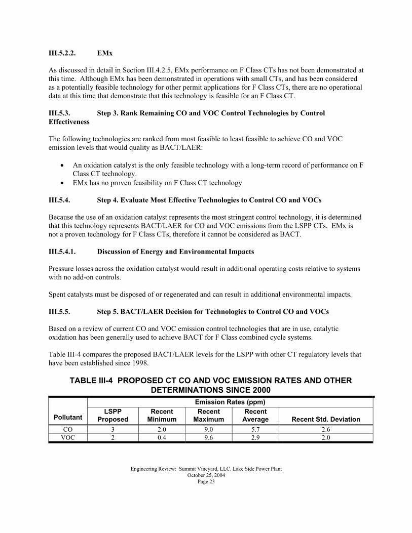
• EMx has no proven feasibility on F Class CT technology III.5.4. Step 4. Evaluate Most Effective Technologies to Control CO and VOCs Because the use of an oxidation catalyst represents the most stringent control technology, it is determined that this technology represents BACT/LAER for CO and VOC emissions from the LSPP CTs. EMx is not a proven technology for F Class CTs, therefore it cannot be considered as BACT. III.5.4.1. Discussion of Energy and Environmental Impacts Pressure losses across the oxidation catalyst would result in additional operating costs relative to systems with no add-on controls. Spent catalysts must be disposed of or regenerated and can result in additional environmental impacts. III.5.5. Step 5. BACT/LAER Decision for Technologies to Control CO and VOCs Based on a review of current CO and VOC emission control technologies that are in use, catalytic oxidation has been generally used to achieve BACT for F Class combined cycle systems. Table III-4 compares the proposed BACT/LAER levels for the LSPP with other CT regulatory levels that have been established since 1998.
TABLE III-4 PROPOSED CT CO AND VOC EMISSION RATES AND OTHER DETERMINATIONS SINCE 2000
Emission Rates (ppm)
Pollutant LSPP
Proposed Recent
Minimum Recent
Maximum Recent
Average Recent Std. Deviation CO 3 2.0 9.0 5.7 2.6
VOC 2 0.4 9.6 2.9 2.0
Engineering Review: Summit Vineyard, LLC. Lake Side Power Plant October 25, 2004 Page 24
It is proposed that an oxidation catalyst will be installed to control CO and VOC emissions to 3 ppm and 2ppm, respectively. These limits are consistent with the lowest proposed control efficiencies for recently permitted F Class combined cycle facilities, including similar facilities in Utah. The proposed averaging period for CO is 3-hour. The proposed averaging period for VOC is 3-hour as determined by a performance test. III.6 TECHNOLOGY ASSESSMENT TO CONTROL EMISSIONS OF PM10 Emissions of PM10 from CTs are generally related to condensable sulfur compounds. Thus the use low sulfur fuels such as natural gas minimizes the formation of PM10. Some PM10 also results from particulates entrained in the CT inlet air. III.6.1. Step 1. Identify All Technologies to Control PM10 Although added controls for PM10 emissions have never been required for natural gas combustion sources, various technologies are available to control them. These control technologies include:
• Baghouses (Fabric Filters) • Electrostatic Precipitators (ESP) • Wet Scrubbers • Use of Low Sulfur Fuel
III.6.1.1. Baghouses Baghouses use arrays of fabric filters to capture dust particles in the exhaust stream. The filters are cleaned periodically and the collected material is either disposed as waste or recycled back into the process. The effectiveness of a baghouse depends on particle size and on a �cake� of particulate that forms on the upstream side of the filter. The periodic cleaning of the filter maintains the cake, pressure loss, and efficiency at a desired level. III.6.1.2. ESPs ESPs ionize particles and liquid droplets in the exhaust, which are collected on charged plates. The plates are periodically cleaned to maintain the efficiency of the system. The material collected is subsequently disposed as waste. Although this system can be highly efficient, it also requires large amounts of electricity and space. III.6.1.3. Wet Scrubbers A variety of wet scrubbers can be used to control emissions of PM10 including spray chambers and venturi scrubbers. Like baghouses, the efficiency of a wet scrubber depends on the size of the particulate. The slurry of water and collected material is subsequently disposed as waste. III.6.1.4. Use of Low Sulfur Fuel Emissions of PM10 from combustions turbines is primarily related to the formation of sulfates in the
Engineering Review: Summit Vineyard, LLC. Lake Side Power Plant October 25, 2004 Page 25
exhaust. Thus, the use of low sulfur fuel lowers formation of sulfate. III.6.2. Step 2. Eliminate Technically Infeasible Options to Control Emissions of PM10 Although substantial ancillary facilities would be constructed to implement the add-on control strategies discussed in Section III.6.1, it is assumed that it would be feasible to implement them. III.6.3. Step 3. Rank Remaining Technologies to Control Emissions of PM10 It is possible that the control effectiveness of add-on control technologies discussed in Section III.6.1 may all be similar, although wet scrubbers are typically expected to be the least efficient. Based on the lack of empirical data, it is impossible to estimate the control efficiencies. Data that have been collected and control efficiencies that have been identified for exhausts with high particulate loadings (such as mineral processing and coal fired combustion sources) are not applicable to an exhaust with a significantly lower particulate loading. Particulate emissions related to natural gas combustion are not efficiently removed using controls such as baghouses and wet scrubbers. ESPs may be more effective but require a large amount of electricity and space. Without data to assess or support any add-on controls for removal of PM10, these efficiencies cannot be evaluated. The potential costs and risks are unknown without empirical data. It can also be assumed that all the add-on control technologies would require substantial additional facilities. The use of low sulfur fuel is selected as BACT/LAER for control of PM10. Add-on controls cannot be selected as BACT/LAER based on the following:
• Lack of data on control effectiveness, • Significant additional facilities that are required to operate these systems, • Significant energy requirements, and • Environmental impacts associated with waste handling.
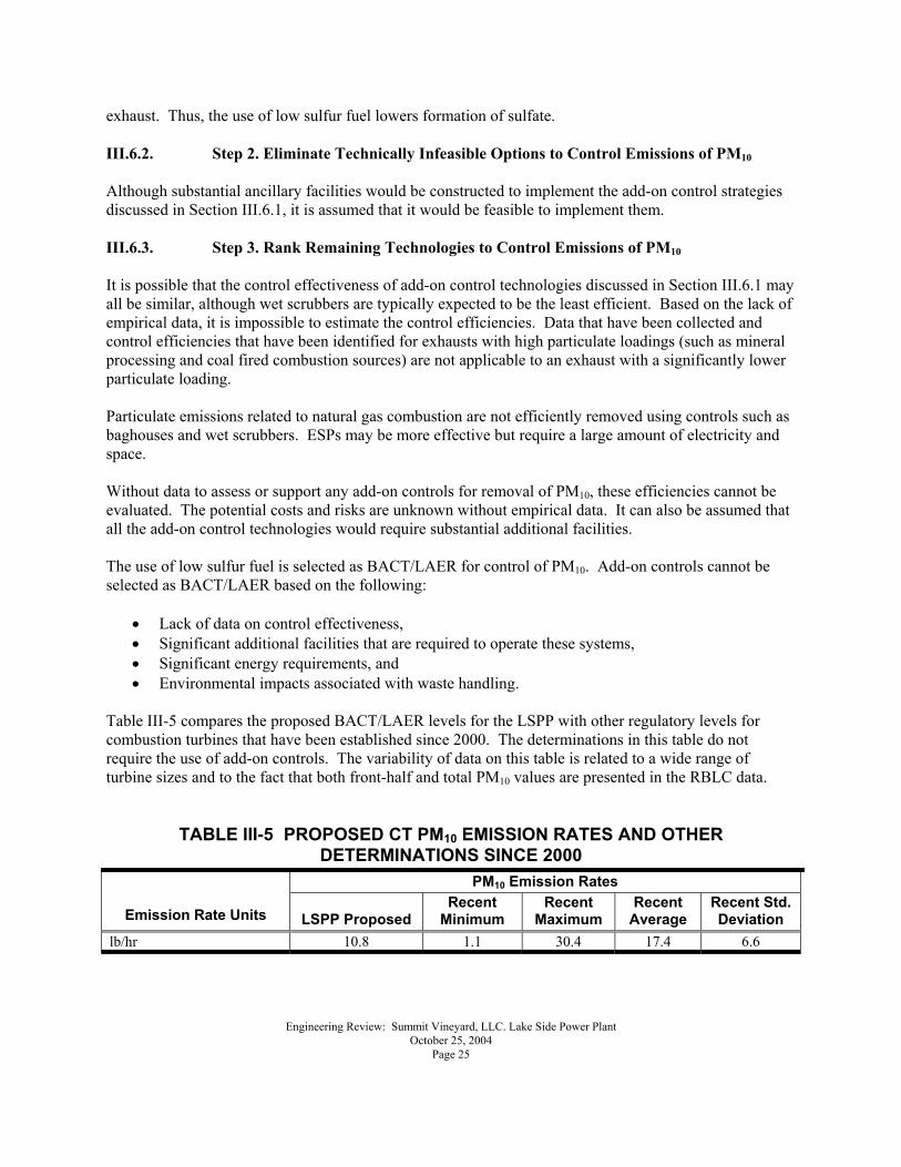
Table III-5 compares the proposed BACT/LAER levels for the LSPP with other regulatory levels for combustion turbines that have been established since 2000. The determinations in this table do not require the use of add-on controls. The variability of data on this table is related to a wide range of turbine sizes and to the fact that both front-half and total PM10 values are presented in the RBLC data.
TABLE III-5 PROPOSED CT PM10 EMISSION RATES AND OTHER DETERMINATIONS SINCE 2000
PM10 Emission Rates
Emission Rate Units LSPP Proposed Recent
Minimum Recent
Maximum Recent
Average Recent Std. Deviation
lb/hr 10.8 1.1 30.4 17.4 6.6
Engineering Review: Summit Vineyard, LLC. Lake Side Power Plant October 25, 2004 Page 26
III.7 TECHNOLOGY ASSESSMENT TO CONTROL SO2 Emissions of SO2 result from the combustion of fuel-bound sulfur. Fuels such as natural gas have the lowest concentrations of sulfur compounds. This section evaluates BACT/LAER for the control of SO2 emissions from natural gas fired CTs. III.7.1. Control Technologies for SO2 Emissions Add-on controls for emissions of SO2 have never been required for natural gas fired CTs. Various technologies have been developed to control these emissions from combustion sources that use fuel oil and coal. These control technologies include:
• Wet Limestone Scrubbers • Dry Limestone Scrubbers • Use of Low Sulfur Fuel
Although fuel desulfurization is also considered as a control technology for SO2, it is assumed that it would not be applicable for a low-sulfur fuel such as natural gas. III.7.1.1. Wet Limestone Scrubbers Wet scrubbers use a spray of limestone slurry to absorb the sulfur compounds in the flue gases. The reaction between the slurry and the exhaust occurs in a spray tower where the slurry flows counter-current to the exhaust gases. The reacted slurry contains calcium sulfite and calcium sulfate that must be removed from the process and disposed as waste. III.7.1.2. Dry Limestone Scrubbers Dry limestone scrubbers use a similar process as the wet scrubbers. The difference is the amount of water in the slurry. In dry scrubbing, the water is evaporated during the reaction process, leaving fine particulates of calcium sulfite and calcium sulfate that must, subsequently, be removed from the exhaust. III.7.1.3. Low Sulfur Fuel This control strategy involves the use of low sulfur fuels such as natural gas in lieu of other fuels such as fuel oil. III.7.2. Assessment of Technologies to Control Emissions of SO2 A review of recently permitted natural gas fired CTs shows that exhaust scrubbing controls have never been used on these plants. Because of this lack of evidence for the feasibility of the scrubbing controls, these controls are eliminated as potential BACT for this application. Energy loss impacts would result from the operation of the scrubbers. Wet and dry scrubbers cause additional pressure drops, and the dry scrubbers cause additional energy losses across the baghouse. In addition, energy losses also result from the various pumps and motors that are required to drive these
Engineering Review: Summit Vineyard, LLC. Lake Side Power Plant October 25, 2004 Page 27
systems. Environmental impacts are associated with the operation of scrubbers. Both wet and dry scrubbers require disposal of the calcium sulfites and calcium sulfates that are generated by these processes. In addition, both systems would result in higher water use at the facility. Therefore, wet or dry scrubbing systems cannot be selected as BACT for the following reasons:
• Lack of data on feasibility, • Significant additional facilities that are required to operate these systems, • Significant energy requirements, and • Environmental impacts associated with waste handling.
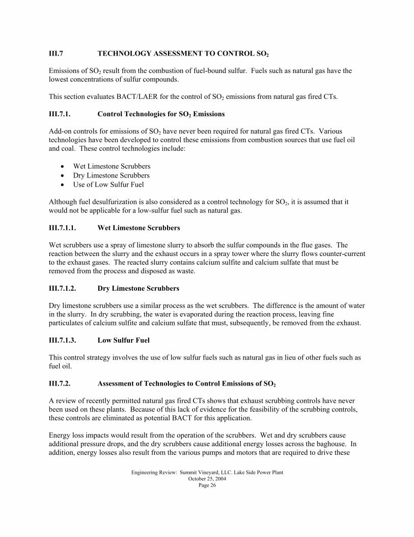
The use of low sulfur fuel is selected as BACT/LAER for controlling SO2 emissions from the LSPP CTs. Table III-6 compares the proposed BACT/LAER levels for the LSPP with other regulatory levels for CTs that have been established since 2000. None of the determinations in these tables required the use of add-on controls.
TABLE III-6 PROPOSED CT SO2 EMISSION RATES AND OTHER DETERMINATIONS SINCE 2000
SO2 Emission Rates Emission Rate Units
LSPP Proposed
Recent Minimum
Recent Maximum
Recent Average
Recent Std. Deviation
lb/hr 3.1 0.1 28.2 8.0 6.4 III.8. BACT/LAER DETERMINATIONS FOR ANCILLARY SOURCES The ancillary sources at LSPP considered in this analysis include:
• An auxiliary boiler, • A fuel dew point heater, • A fire pump, • A standby generator, and • A ten-cell cooling tower.
III.8.1. Auxiliary Boiler and Fuel Dew Point Heater This analysis supports the selection of BACT and LAER for the LSPP auxiliary boiler and fuel dew point heater for control of emissions of NOx, PM10, CO, SO2, and VOCs. The auxiliary boiler is a natural gas-fired industrial package boiler that has a maximum fuel burn rate of 49 MMBTU/hr. To ensure operational flexibility, the current application proposes that the auxiliary boiler will operate a maximum of 8,760 hours per year. The fuel dew point heater is a natural gas-fired water bath heater that has a maximum fuel burn rate of 4.0
Engineering Review: Summit Vineyard, LLC. Lake Side Power Plant October 25, 2004 Page 28
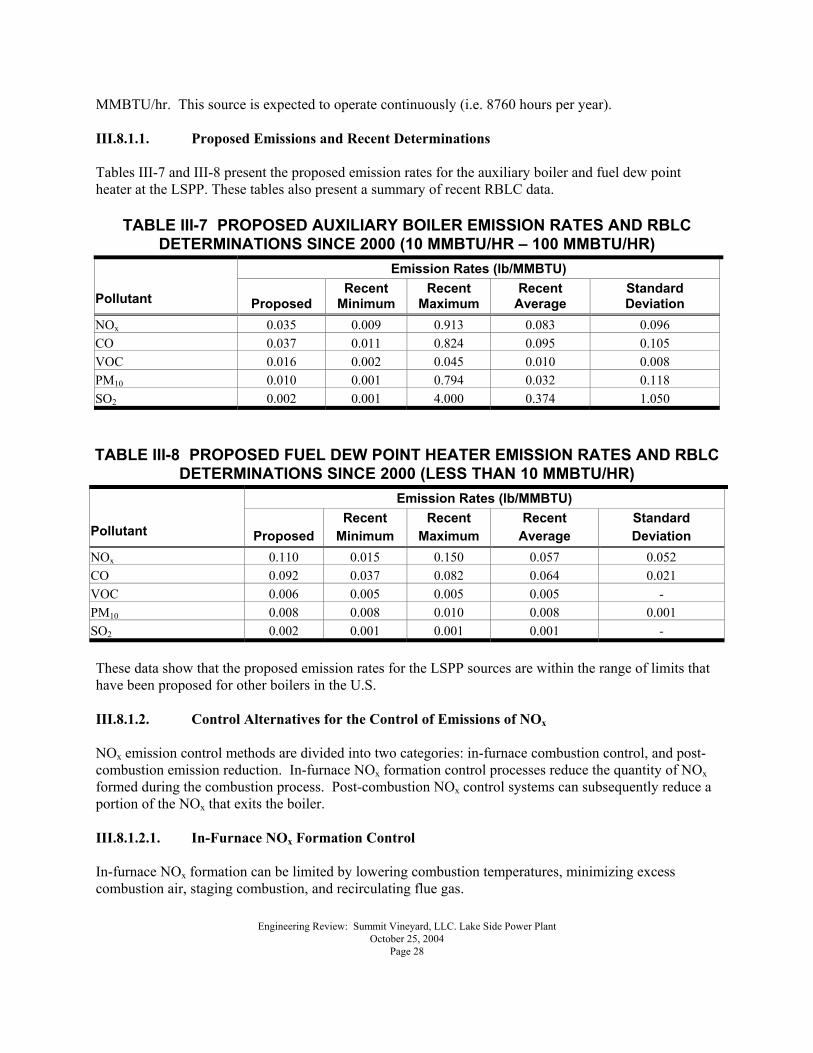
MMBTU/hr. This source is expected to operate continuously (i.e. 8760 hours per year). III.8.1.1. Proposed Emissions and Recent Determinations Tables III-7 and III-8 present the proposed emission rates for the auxiliary boiler and fuel dew point heater at the LSPP. These tables also present a summary of recent RBLC data.
TABLE III-7 PROPOSED AUXILIARY BOILER EMISSION RATES AND RBLC DETERMINATIONS SINCE 2000 (10 MMBTU/HR � 100 MMBTU/HR)
Emission Rates (lb/MMBTU)
Pollutant Proposed Recent
Minimum Recent
Maximum Recent
Average Standard Deviation
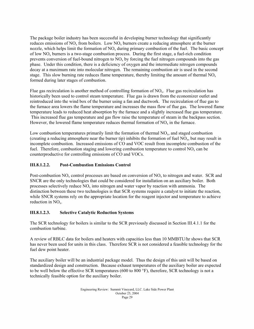
NOx 0.035 0.009 0.913 0.083 0.096 CO 0.037 0.011 0.824 0.095 0.105 VOC 0.016 0.002 0.045 0.010 0.008 PM10 0.010 0.001 0.794 0.032 0.118 SO2 0.002 0.001 4.000 0.374 1.050 TABLE III-8 PROPOSED FUEL DEW POINT HEATER EMISSION RATES AND RBLC
DETERMINATIONS SINCE 2000 (LESS THAN 10 MMBTU/HR) Emission Rates (lb/MMBTU)
Pollutant Proposed Recent
Minimum Recent
Maximum Recent
Average Standard Deviation
NOx 0.110 0.015 0.150 0.057 0.052 CO 0.092 0.037 0.082 0.064 0.021 VOC 0.006 0.005 0.005 0.005 - PM10 0.008 0.008 0.010 0.008 0.001 SO2 0.002 0.001 0.001 0.001 - These data show that the proposed emission rates for the LSPP sources are within the range of limits that have been proposed for other boilers in the U.S. III.8.1.2. Control Alternatives for the Control of Emissions of NOx NOx emission control methods are divided into two categories: in-furnace combustion control, and post-combustion emission reduction. In-furnace NOx formation control processes reduce the quantity of NOx formed during the combustion process. Post-combustion NOx control systems can subsequently reduce a portion of the NOx that exits the boiler. III.8.1.2.1. In-Furnace NOx Formation Control In-furnace NOx formation can be limited by lowering combustion temperatures, minimizing excess combustion air, staging combustion, and recirculating flue gas.
Engineering Review: Summit Vineyard, LLC. Lake Side Power Plant October 25, 2004 Page 29
The package boiler industry has been successful in developing burner technology that significantly reduces emissions of NOx from boilers. Low NOx burners create a reducing atmosphere at the burner nozzle, which helps limit the formation of NOx during primary combustion of the fuel. The basic concept of low NOx burners is a two-stage combustion process. During the first stage, a fuel-rich condition prevents conversion of fuel-bound nitrogen to NOx by forcing the fuel nitrogen compounds into the gas phase. Under this condition, there is a deficiency of oxygen and the intermediate nitrogen compounds decay at a maximum rate into molecular nitrogen. The remaining combustion air is used in the second stage. This slow burning rate reduces flame temperature, thereby limiting the amount of thermal NOx formed during later stages of combustion. Flue gas recirculation is another method of controlling formation of NOx. Flue gas recirculation has historically been used to control steam temperature. Flue gas is drawn from the economizer outlet and reintroduced into the wind box of the burner using a fan and ductwork. The recirculation of flue gas to the furnace area lowers the flame temperature and increases the mass flow of flue gas. The lowered flame temperature leads to reduced heat absorption by the furnace and a slightly increased flue gas temperature. This increased flue gas temperature and gas flow raise the temperature of steam in the backpass section. However, the lowered flame temperature reduces thermal formation of NOx in the furnace. Low combustion temperatures primarily limit the formation of thermal NOx, and staged combustion (creating a reducing atmosphere near the burner tip) inhibits the formation of fuel NOx, but may result in incomplete combustion. Increased emissions of CO and VOC result from incomplete combustion of the fuel. Therefore, combustion staging and lowering combustion temperature to control NOx can be counterproductive for controlling emissions of CO and VOCs. III.8.1.2.2. Post-Combustion Emissions Control Post-combustion NOx control processes are based on conversion of NOx to nitrogen and water. SCR and SNCR are the only technologies that could be considered for installation on an auxiliary boiler. Both processes selectively reduce NOx into nitrogen and water vapor by reaction with ammonia. The distinction between these two technologies is that SCR systems require a catalyst to initiate the reaction, while SNCR systems rely on the appropriate location for the reagent injector and temperature to achieve reduction in NOx. III.8.1.2.3. Selective Catalytic Reduction Systems The SCR technology for boilers is similar to the SCR previously discussed in Section III.4.1.1 for the combustion turbine. A review of RBLC data for boilers and heaters with capacities less than 10 MMBTU/hr shows that SCR has never been used for units in this class. Therefore SCR is not considered a feasible technology for the fuel dew point heater. The auxiliary boiler will be an industrial package model. Thus the design of this unit will be based on standardized design and construction. Because exhaust temperatures of the auxiliary boiler are expected to be well below the effective SCR temperatures (600 to 800 °F), therefore, SCR technology is not a technically feasible option for the auxiliary boiler.
Engineering Review: Summit Vineyard, LLC. Lake Side Power Plant October 25, 2004 Page 30
III.8.1.2.4. Selective Noncatalytic Reduction Systems Selective noncatalytic NOx reduction systems rely on the appropriate injection temperature for the reagent and reagent/flue gas mixing rather than a catalyst to achieve reductions in NOx. SNCR systems can use either ammonia or urea as a reagent. The ammonia is received and stored as a liquid. The ammonia is vaporized before it is injected into the boiler. Injection is accomplished using either compressed air or steam as a carrier. The injected ammonia then reacts with NOx in the flue gas to form nitrogen and water. Urea is stored as a 50 percent solution in water. This solution is atomized at the injection point to optimize mixing. In this process, the urea molecule dissociates to form two molecules of ammonia that react with NOx in the flue gas to form nitrogen and water. Requirements for location of the injector would be similar for both ammonia- and urea-based SNCR systems. SNCR systems require a fairly narrow temperature range for reagent injection to achieve a specific NOx reduction efficiency. The optimum temperature range for injection of ammonia or urea is 1,500 °F to 2,000 °F. This optimum temperature range occurs in the backpass portion of the boiler. This temperature range will occur at different locations within the boiler, depending on boiler load. Therefore, multiple sets of injection nozzles are required in order to follow the location of the optimum temperature as boiler load changes during normal operation. The NOx reduction efficiency of an SNCR system decreases rapidly at temperatures outside the optimum temperature range. Operation below this temperature range results in excessive emissions of ammonia (slip). Operation above the temperature range results in increased emissions of NOx. Injection of hydrogen or other additives can increase the effective temperature range required for operation of the SNCR. However, regardless of the magnitude of the temperature window, residence times for a specific temperature range are limited, resulting in less than optimum performance. Compared with SCR systems, the SNCR process requires more than twice the theoretical amount of reagent to achieve similar NOx reduction levels. A portion of the ammonia used or generated by the SNCR process reacts with NOx in the flue gas and decomposes into nitrogen and water. The remaining unreacted ammonia exits the system as ammonia slip. Control of ammonia in an SNCR system is difficult. Continuous emissions monitors for measuring ammonia have proven unreliable. Without reliable, accurate monitors, feedback control is compromised and ammonia injection rates cannot be precisely controlled, potentially resulting in excess ammonia slip. Therefore, the use of an SNCR system could result in stack emissions of between 20 and 50 ppm of ammonia. An SNCR system will also increase energy requirements for a given application, requiring fans, air compressors, or a source of steam to provide the necessary motive energy for dilution, atomization, and injection of reagent into the flue gas stream. These additional energy requirements will result in increased annual emissions of other pollutants. In light of the major site-specific considerations such as temperature profile of the package boiler, residence time, and geometry of the boiler (affecting reagent distribution), the potential for reductions of NOx emissions of SNCR systems is severely limited. To date, SNCR systems have not been used on package-type boilers and heaters and are not considered feasible for this application. III.8.1.2.5. Auxiliary Boiler and Fuel Dew Point Heater NOx LAER Conclusions
Engineering Review: Summit Vineyard, LLC. Lake Side Power Plant October 25, 2004 Page 31
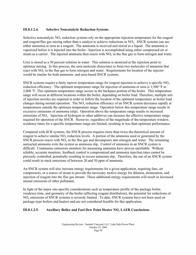
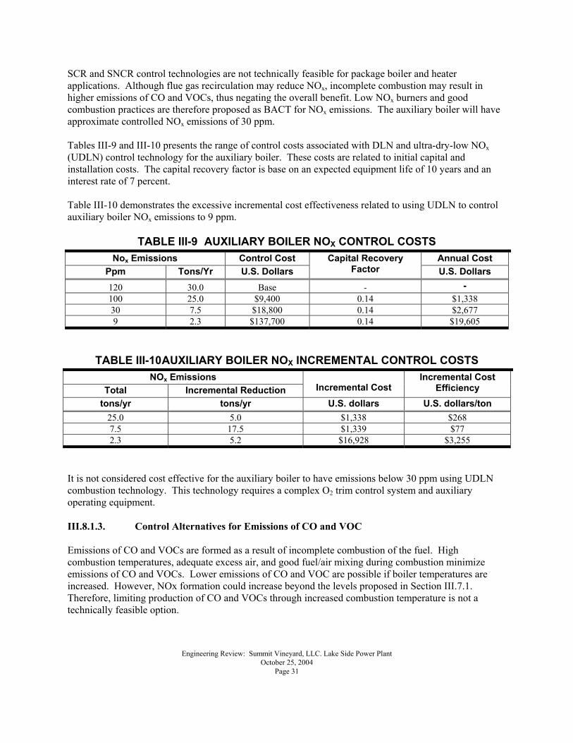
SCR and SNCR control technologies are not technically feasible for package boiler and heater applications. Although flue gas recirculation may reduce NOx, incomplete combustion may result in higher emissions of CO and VOCs, thus negating the overall benefit. Low NOx burners and good combustion practices are therefore proposed as BACT for NOx emissions. The auxiliary boiler will have approximate controlled NOx emissions of 30 ppm. Tables III-9 and III-10 presents the range of control costs associated with DLN and ultra-dry-low NOx (UDLN) control technology for the auxiliary boiler. These costs are related to initial capital and installation costs. The capital recovery factor is base on an expected equipment life of 10 years and an interest rate of 7 percent. Table III-10 demonstrates the excessive incremental cost effectiveness related to using UDLN to control auxiliary boiler NOx emissions to 9 ppm.
TABLE III-9 AUXILIARY BOILER NOX CONTROL COSTS Nox Emissions Control Cost Annual Cost
Ppm Tons/Yr U.S. Dollars Capital Recovery
Factor U.S. Dollars 120 30.0 Base - - 100 25.0 $9,400 0.14 $1,338 30 7.5 $18,800 0.14 $2,677 9 2.3 $137,700 0.14 $19,605
TABLE III-10 AUXILIARY BOILER NOX INCREMENTAL CONTROL COSTS NOx Emissions
Total Incremental Reduction Incremental Cost Incremental Cost
Efficiency tons/yr tons/yr U.S. dollars U.S. dollars/ton
25.0 5.0 $1,338 $268 7.5 17.5 $1,339 $77 2.3 5.2 $16,928 $3,255
It is not considered cost effective for the auxiliary boiler to have emissions below 30 ppm using UDLN combustion technology. This technology requires a complex O2 trim control system and auxiliary operating equipment. III.8.1.3. Control Alternatives for Emissions of CO and VOC Emissions of CO and VOCs are formed as a result of incomplete combustion of the fuel. High combustion temperatures, adequate excess air, and good fuel/air mixing during combustion minimize emissions of CO and VOCs. Lower emissions of CO and VOC are possible if boiler temperatures are increased. However, NOx formation could increase beyond the levels proposed in Section III.7.1. Therefore, limiting production of CO and VOCs through increased combustion temperature is not a technically feasible option.
Engineering Review: Summit Vineyard, LLC. Lake Side Power Plant October 25, 2004 Page 32
An oxidation catalytic emission reduction system is available for use on the exhaust from combustion turbines. The oxidation catalyst could be installed at the boiler exit. However, the temperature of flue gas that exits the proposed package boiler will be approximately 400°F. As previously noted, the optimum temperature range of flue gas for operation of a catalyst to reduce emissions of CO and VOCs is between 700°F and 900°F. Accordingly, the range of temperatures available in an auxiliary boiler is less than optimum for the oxidation catalyst, making the oxidation catalyst an undesirable option. The RBLC data indicate that catalytic oxidation has not been required in previous BACT or LAER determinations for boilers and heaters with capacities below 10 MMBTU/hr. Therefore an oxidation catalyst is not considered a feasible technology for the fuel dew point heater. III.8.1.3.1. BACT/LAER Conclusions for Auxiliary Boiler and Fuel Dew Point Heater CO and VOC An oxidation catalyst control system is not considered technically feasible for the auxiliary boiler and fuel dew point heater. Therefore the CO and VOC BACT/LAER proposed for these sources include the use of good combustion control with no add-on controls. III.8.1.4. Control Alternatives for Emissions of PM10 and BACT/LAER Conclusions The RBLC Clearinghouse database does not list any particulate control equipment requirements for 40 CFR Subpart Dc classification boilers that burn natural gas except for the use of good combustion controls. The use of natural gas is proposed as BACT/LAER for emissions of PM10. III.8.1.5. Control Alternatives for Emissions of SO2 and BACT/LAER Conclusions Because the natural gas fuel for the auxiliary boiler and fuel dew point heater is inherently low in sulfur content, additional emissions controls have not been required or developed to reduce emissions further. The use of natural gas is proposed as BACT/LAER for emissions of SO2 from these sources. III.8.2. Emergency Diesel-fueled Fire Pump and Standby Generator This analysis supports selection of BACT/LAER for the LSPP diesel-fueled fire pump and standby diesel generator to control emissions of NOx, PM10, SO2, CO, and VOCs. An emergency diesel-fueled fire pump will be a nominal 290 horsepower (hp) engine and the diesel-fueled standby generator will be a nominal 1490 hp engine. These engines are expected to operate once per week for required testing, and each is expected to operate up to 200 hours annually. III.8.2.1. Proposed Emissions and Recent Determinations Tables III-11 and III-12 present the proposed emission rates for the LSPP standby diesel generator fire pump. This table also presents a summary of recent RBLC data for diesel-fueled fire pumps. With the exception of CO and PM10, which are slightly less than the RBLC minimum, these data show that the proposed emissions are within the range of limits that have been proposed for other diesel-fueled engines.
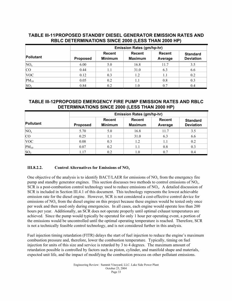
Engineering Review: Summit Vineyard, LLC. Lake Side Power Plant October 25, 2004 Page 33
TABLE III-11 PROPOSED STANDBY DIESEL GENERATOR EMISSION RATES AND
RBLC DETERMINATIONS SINCE 2000 (LESS THAN 2000 HP) Emission Rates (gm/hp-hr)
Pollutant Proposed Recent
Minimum Recent
Maximum Recent
Average Standard Deviation
NOx 6.00 5.0 16.8 11.7 3.5 CO 0.44 1.1 31.0 6.3 6.6 VOC 0.12 0.3 1.2 1.1 0.2 PM10 0.05 0.2 1.1 0.8 0.3 SO2 0.84 0.2 1.0 0.7 0.4 TABLE III-12 PROPOSED EMERGENCY FIRE PUMP EMISSION RATES AND RBLC
DETERMINATIONS SINCE 2000 (LESS THAN 2000 HP) Emission Rates (gm/hp-hr)
Pollutant Proposed Recent
Minimum Recent
Maximum Recent
Average Standard Deviation
NOx 5.70 5.0 16.8 11.7 3.5 CO 0.25 1.1 31.0 6.3 6.6 VOC 0.08 0.3 1.2 1.1 0.2 PM10 0.07 0.2 1.1 0.8 0.3 SO2 1.17 0.2 1.0 0.7 0.4
III.8.2.2. Control Alternatives for Emissions of NOx One objective of the analysis is to identify BACT/LAER for emissions of NOx from the emergency fire pump and standby generator engines. This section discusses two methods to control emissions of NOx. SCR is a post-combustion control technology used to reduce emissions of NOx. A detailed discussion of SCR is included in Section III.4.1 of this document. This technology represents the lowest achievable emission rate for the diesel engine. However, SCR is not considered a cost-effective control device for emissions of NOx from the diesel engine on this project because these engines would be tested only once per week and then used only during emergencies. In all cases, each engine would operate less than 200 hours per year. Additionally, an SCR does not operate properly until optimal exhaust temperatures are achieved. Since the pump would typically be operated for only 1 hour per operating event, a portion of the emissions would be uncontrolled until the optimal operating temperature is reached. Therefore, SCR is not a technically feasible control technology, and is not considered further in this analysis. Fuel injection timing retardation (FITR) delays the start of fuel injection to reduce the engine�s maximum combustion pressure and, therefore, lower the combustion temperature. Typically, timing on fuel injection for units of this size and service is retarded by 3 to 4 degrees. The maximum amount of retardation possible is controlled by factors such as piston, cylinder, and manifold shape and materials, expected unit life, and the impact of modifying the combustion process on other pollutant emissions.
Engineering Review: Summit Vineyard, LLC. Lake Side Power Plant October 25, 2004 Page 34
Retarding the timing of fuel injection can reduce emissions of NOx by 20 to 30 percent, depending on the unit service, size, and design. However, combustion efficiency of a diesel engine decreases with an increase in timing retardation, thereby reducing the maximum efficiency of the fire pump when it is needed in emergencies. Additionally, this method increases the emissions of other pollutants such as CO, VOCs, and particulate matter. Therefore, FITR is not a technically feasible control technology, and is not considered further in this analysis. III.8.2.2.1. Fire Pump and standby Generator BACT/LAER Conclusions for Emissions of NOx SCR is not considered a cost-effective alternative for reduction in NOx for the diesel fueled engines because each will operate only a maximum of 200 hours per years. FITR is not considered because it would reduce the efficiency of the engines when they are needed most during emergencies and because the reduction in annual emissions and ambient air impacts would be minimal compared with cost. For these reasons, proper combustion control is proposed as BACT/LAER for NOx emissions. III.8.2.3. Alternatives for Control Emissions of CO and VOC CO and VOCs are formed as a result of incomplete oxidation of hydrocarbons contained in the fuel. Combustion controls such as high combustion temperatures, adequate excess air, and good fuel/air mixing during combustion will minimize formation of CO and VOCs. Formation of NOx however, is increased by combustion control efforts to minimize emissions of CO and VOCs. Because of this inverse relationship, increased NOx emissions must always be considered when identifying CO and VOC emissions controls. Post-combustion control technologies, such as an oxidation catalyst, could reduce emissions of CO and VOCs. An oxidation catalyst could be located at the diesel engine exhaust. This option could reduce emissions of CO and VOCs by 50 to 80 percent. Catalytic oxidation is not considered a cost-effective emission control device for CO and VOCs from the diesel engines based on the intermittent and limited operating hours. Because oxidation catalysts operate in an optimal temperature range, they would not be as effective for this type of source that operates intermittently and for very short periods. Therefore, catalytic oxidation is not considered further in this analysis. III.8.2.3.1. BACT/LAER Conclusions for Emissions of CO and VOCs from the Fire Pump and Standby Generator Proper combustion controls are proposed as CO and VOC BACT/LAER for the emergency diesel-fueled fire pump. III.8.2.4. Control Alternatives for Emissions of PM10 and BACT/LAER Conclusions Based on the limited operating hours, it is anticipated that uncontrolled emissions of PM10 from these engines will be minimal and will be controlled by ensuring complete combustion of the fuel, as recommended by the manufacturer�s standard operating procedures. Accordingly, inlet air filtering and good combustion control are proposed as BACT/LAER for the LSPP fire pump and standby generator for controlling emissions of PM10. III.8.2.5. Control Alternatives for Emissions of SO2 and BACT/LAER Conclusions
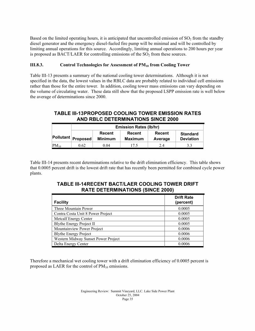
Engineering Review: Summit Vineyard, LLC. Lake Side Power Plant October 25, 2004 Page 35
Based on the limited operating hours, it is anticipated that uncontrolled emission of SO2 from the standby diesel generator and the emergency diesel-fueled fire pump will be minimal and will be controlled by limiting annual operations for this source. Accordingly, limiting annual operations to 200 hours per year is proposed as BACT/LAER for controlling emissions of the SO2 from these sources. III.8.3. Control Technologies for Assessment of PM10 from Cooling Tower Table III-13 presents a summary of the national cooling tower determinations. Although it is not specified in the data, the lowest values in the RBLC data are probably related to individual cell emissions rather than those for the entire tower. In addition, cooling tower mass emissions can vary depending on the volume of circulating water. These data still show that the proposed LSPP emission rate is well below the average of determinations since 2000.
TABLE III-13 PROPOSED COOLING TOWER EMISSION RATES AND RBLC DETERMINATIONS SINCE 2000
Emission Rates (lb/hr)
Pollutant Proposed Recent
Minimum Recent
Maximum Recent
Average Standard Deviation
PM10 0.62 0.04 17.5 2.4 3.3 Table III-14 presents recent determinations relative to the drift elimination efficiency. This table shows that 0.0005 percent drift is the lowest drift rate that has recently been permitted for combined cycle power plants.
TABLE III-14 RECENT BACT/LAER COOLING TOWER DRIFT RATE DETERMINATIONS (SINCE 2000)
Facility Drift Rate (percent)
Three Mountain Power 0.0005 Contra Costa Unit 8 Power Project 0.0005 Metcalf Energy Center 0.0005 Blythe Energy Project II 0.0005 Mountainview Power Project 0.0006 Blythe Energy Project 0.0006 Western Midway Sunset Power Project 0.0006 Delta Energy Center 0.0006
Therefore a mechanical wet cooling tower with a drift elimination efficiency of 0.0005 percent is proposed as LAER for the control of PM10 emissions.
Engineering Review: Summit Vineyard, LLC. Lake Side Power Plant October 25, 2004 Page 36
III.9. MODELING ANALYSIS The following modeling analysis is based on the original NOI prepared by Greystone Environmental Consultants, Inc. of Greenwood Village, Colorado. It was submitted on behalf of the Applicant and received by the Division on May 21, 2004. One change from the modeling analysis is in terms of CO, which was changed to 3.0 ppm on a 3-hour average as discussed in the BACT review given above. III.9.1. OBJECTIVE The facility will consist of two combustion turbines and one heat recovery steam generator (HRSG) with a gross capacity of 500 MW. The proposed increase in emissions associated with the construction of this unit constitutes a new major source subject to the Prevention of Significant Deterioration (PSD) permitting rules. The rules require the Applicant to include an air quality impact analysis (AQIA) of the proposed project�s impact on federal air quality standards and air quality related values, as part of a complete NOI. This report prepared by the Staff of the Technical Analysis Section (TAS) contains a review of the Applicant�s AQIA including the methodology, data sources, assumptions and modeling results used to determine compliance with State and Federal air quality standards. The AQIA document reviewed and referenced in this report is the �Notice of Intent and Prevention Of Significant Deterioration Air Quality Application � Lake Side Power Plant.� III.9.2. APPLICABLE RULES AND ANALYSES III.9.2.1. Utah Air Quality Rules UDAQ has determined that the Applicant�s NOI is subject to the following rules for conducting an AQIA: R307-401-2 Notice of Intent Requirements R307-401-6 Condition for Issuing an Approval Order R307-403-3 Review of Major Sources of Air Quality Impact R307-405-6 PSD Areas � New Sources and Modifications R307-406-2 Visibility � Source Review R307-410-2 Use of Dispersion Models R307-410-3 Modeling of Criteria Pollutant Impacts in Attainment Areas R307-410-4 Documentation of Ambient Air Impacts for Hazardous Air Pollutants (HAPs) III.9.2.2. Applicability The proposed increases in emissions of NOx, CO, and formaldehyde exceed the emission thresholds outlined in R307-406-5, R307-410-3, and R307-410-4. Therefore, an AQIA consistent with the requirements of R307-405-6, R307-406-2, R307-410-2, and R307-410-4 was submitted as part of the Applicant�s NOI. R307-410-2 and 3 provides further clarification by assigning the burden for conducting AQIAs, and establishes the U. S. Environmental Protection Agency (US EPA) � Guideline on Air Quality Models as a formal basis for defining the scope of the analysis, as well as the model�s construction. The results of the AQIA are required to demonstrate the proposed project�s impact on state and federal air quality standards, acceptable levels of impact, and action triggering thresholds referenced or listed in R307-401-6(2), R307-401-6(3), R307-403-3(1), R307-403-5(1)(a), R307-405-4(1), R307-405-6(2),
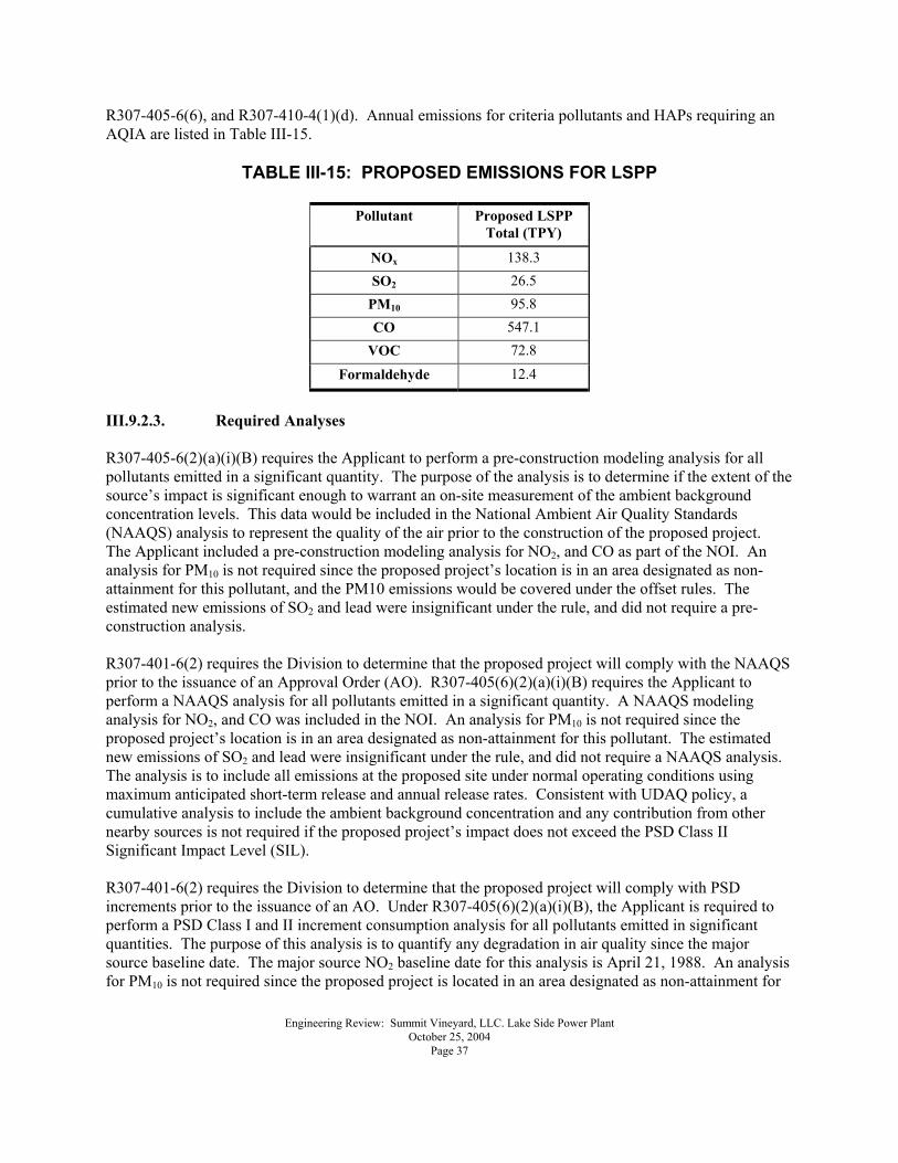
Engineering Review: Summit Vineyard, LLC. Lake Side Power Plant October 25, 2004 Page 37
R307-405-6(6), and R307-410-4(1)(d). Annual emissions for criteria pollutants and HAPs requiring an AQIA are listed in Table III-15.
TABLE III-15: PROPOSED EMISSIONS FOR LSPP
Pollutant Proposed LSPP Total (TPY)
NOx 138.3 SO2 26.5
PM10 95.8 CO 547.1
VOC 72.8
Formaldehyde 12.4
III.9.2.3. Required Analyses R307-405-6(2)(a)(i)(B) requires the Applicant to perform a pre-construction modeling analysis for all pollutants emitted in a significant quantity. The purpose of the analysis is to determine if the extent of the source�s impact is significant enough to warrant an on-site measurement of the ambient background concentration levels. This data would be included in the National Ambient Air Quality Standards (NAAQS) analysis to represent the quality of the air prior to the construction of the proposed project. The Applicant included a pre-construction modeling analysis for NO2, and CO as part of the NOI. An analysis for PM10 is not required since the proposed project�s location is in an area designated as non-attainment for this pollutant, and the PM10 emissions would be covered under the offset rules. The estimated new emissions of SO2 and lead were insignificant under the rule, and did not require a pre-construction analysis. R307-401-6(2) requires the Division to determine that the proposed project will comply with the NAAQS prior to the issuance of an Approval Order (AO). R307-405(6)(2)(a)(i)(B) requires the Applicant to perform a NAAQS analysis for all pollutants emitted in a significant quantity. A NAAQS modeling analysis for NO2, and CO was included in the NOI. An analysis for PM10 is not required since the proposed project�s location is in an area designated as non-attainment for this pollutant. The estimated new emissions of SO2 and lead were insignificant under the rule, and did not require a NAAQS analysis. The analysis is to include all emissions at the proposed site under normal operating conditions using maximum anticipated short-term release and annual release rates. Consistent with UDAQ policy, a cumulative analysis to include the ambient background concentration and any contribution from other nearby sources is not required if the proposed project�s impact does not exceed the PSD Class II Significant Impact Level (SIL). R307-401-6(2) requires the Division to determine that the proposed project will comply with PSD increments prior to the issuance of an AO. Under R307-405(6)(2)(a)(i)(B), the Applicant is required to perform a PSD Class I and II increment consumption analysis for all pollutants emitted in significant quantities. The purpose of this analysis is to quantify any degradation in air quality since the major source baseline date. The major source NO2 baseline date for this analysis is April 21, 1988. An analysis for PM10 is not required since the proposed project is located in an area designated as non-attainment for
Engineering Review: Summit Vineyard, LLC. Lake Side Power Plant October 25, 2004 Page 38
this pollutant. New emissions of SO2 were insignificant under the rule, and did not require an increment analysis. The analysis is to include all increment consuming emissions at the proposed site under normal operating conditions using maximum anticipated short-term and annual release rates. A cumulative analysis to include contributions associated with growth and other increment consuming sources is not required if the proposed project�s impact does not exceed the PSD Class I or II SIL. R307-410-4 requires the Applicant to perform a HAPs analysis for any pollutant emitted above a pollutant specific emission threshold value. This analysis is to include all emissions of the pollutants resulting from the proposed modification under normal operating conditions using maximum anticipated one-hour release rates. The Applicant included an analysis for formaldehyde as part of the NOI. Under R307-405-6(2)(a)(i)(B) and R307-406-2, the Applicant is required to perform a plume blight and regional haze analysis to address impacts from the proposed project on visibility in the Class I areas of concern. A plume blight analysis is required to determine if plumes emanating from the proposed project would be visible inside the Class I area. A regional haze analysis is required to determine if the plumes would reduce the visual range of an observer inside the Class I area. The plume blight analysis is to include all emissions of NO2 and SO4. The regional haze analysis is to include all emissions of SO2, SO4, and NO2. Contributions to model predicted plume visibility and haze-induced reductions in background visual range inside the Class I areas resulting from PM10 emissions, are exempt from the analyses, since the source is proposing to locate in a PM10 non-attainment area. Both analyses are to include emissions from the proposed project under normal operating conditions with maximum anticipated 24-hour emission rates. R307-405-6(2)(a)(i)(D) requires the Applicant to perform a soils and vegetation analysis. The analysis should quantify deposition rates for nitrate and sulfate in the Class I areas. This analysis is to include all emissions of NO2 at the proposed site under normal operating conditions with maximum anticipated annual emission rates. III.10. ON-SITE PRE-CONSTRUCTION MONITORING III.10.1. Meteorological Data Consistent with the US EPA - Meteorological Monitoring Guidance for Regulatory Modeling Applications, on-site data collection using a 10-meter tower was conducted throughout the 1990s by Geneva Steel at a site two kilometers south-southeast of the proposed LSPP site. Parameters collected on-site included wind speed and direction, standard deviation of the wind direction (sigma theta), and temperature. For the purpose of this analysis, five years of meteorological data (1995 and 1997 through 2000) from this site was used to simulate dispersion in the near-field analyses. On-site 1996 data was excluded due to equipment malfunctions that resulted in PSD quality control deficiencies (data collection rate less than 90%). III.10.2. Ambient Pollutant Data A preliminary analysis was conducted to determine the necessity for pre-construction ambient pollutant monitoring. The modeling results were compared against R307-405-6(6) � Exemptions - Monitoring Requirements. The results indicated that NO2 and CO concentrations were less than the monitoring
Engineering Review: Summit Vineyard, LLC. Lake Side Power Plant October 25, 2004 Page 39
trigger level listed in the rule; and therefore, no pre-construction monitoring was required for either pollutant. III.11. MODEL SELECTION The Industrial Source Complex Short Term -Version 3 (ISCST3) is the preferred model specified in the US EPA � Guideline on Air Quality Models to predict air pollutant concentrations in the near field (within 50 kilometers of the source). The US EPA - CALPUFF - Version 5.5 model is the preferred model to predict concentrations in the far field (long range transport conditions beyond 50 kilometers from the source). III.12. MODELING INPUTS AND ASSUMPTIONS III.12.1. Technical Options The regulatory default options were selected in ISCST3 - PRIME by the Applicant to quantify all concentrations. The CALPUFF model options and assumptions used in the analysis are discussed in Section 7 of the NOI. III.12.2. Urban or Rural Area Designation A review of the appropriate 7.5-minute quadrangles determined that the area should be classified as �rural� for air modeling purposes. III.12.3. Topography/Terrain The Plant is at an elevation of 4510 feet with distant terrain features that have little affect on concentration predictions.
• Zone: 12 • Location: UTM (NAD27): 435955 meters East, 4464582 meters North
III.12.4. Ambient Air It was determined that the Plant boundary used in the AQIA meets the State�s definition of an ambient air boundary. III.12.5. Receptor and Terrain Elevations The near-field modeling domain (20 km x 20 km) used by the Applicant consisted of ~22,000 Cartesian grid receptors including property boundary receptors. The modeling domain has simple and complex terrain features in the near field. Therefore, receptor points representing actual terrain elevations from the area were used in the analysis. The far-field modeling domain consisted of the area covered under an arc extending ±45° either side of the vector from the proposed site to the Class I areas being evaluated, and having a radius equal to the distance between the two points plus 50 kilometers. Three receptor rings were created for each of the
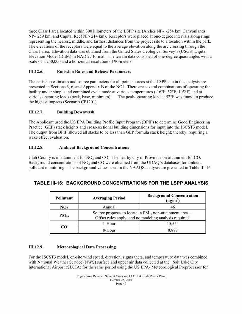
Engineering Review: Summit Vineyard, LLC. Lake Side Power Plant October 25, 2004 Page 40
three Class I area located within 300 kilometers of the LSPP site (Arches NP- ~254 km, Canyonlands NP� 259 km, and Capital Reef NP- 214 km). Receptors were placed at one-degree intervals along rings representing the nearest, middle, and farthest distances from the project site to a location within the park. The elevations of the receptors were equal to the average elevation along the arc crossing through the Class I area. Elevation data was obtained from the United States Geological Survey�s (USGS) Digital Elevation Model (DEM) in NAD 27 format. The terrain data consisted of one-degree quadrangles with a scale of 1:250,000 and a horizontal resolution of 90-meters. III.12.6. Emission Rates and Release Parameters The emission estimates and source parameters for all point sources at the LSPP site in the analysis are presented in Sections 3, 6, and Appendix B of the NOI. There are several combinations of operating the facility under simple and combined cycle mode at various temperatures (-16°F, 52°F, 105°F) and at various operating loads (peak, base, minimum). The peak-operating load at 52°F was found to produce the highest impacts (Scenario CP1201). III.12.7. Building Downwash The Applicant used the US EPA Building Profile Input Program (BPIP) to determine Good Engineering Practice (GEP) stack heights and cross-sectional building dimensions for input into the ISCST3 model. The output from BPIP showed all stacks to be less than GEP formula stack height; thereby, requiring a wake effect evaluation. III.12.8. Ambient Background Concentrations Utah County is in attainment for NO2 and CO. The nearby city of Provo is non-attainment for CO. Background concentrations of NO2 and CO were obtained from the UDAQ�s databases for ambient pollutant monitoring. The background values used in the NAAQS analysis are presented in Table III-16.
TABLE III-16: BACKGROUND CONCENTRATIONS FOR THE LSPP ANALYSIS
Pollutant Averaging Period Background Concentration (µg/m3)
NO2 Annual 46
PM10 Source proposes to locate in PM10 non-attainment area � Offset rules apply, and no modeling analysis required.
1-Hour 15,554 CO
8-Hour 8,888 III.12.9. Meteorological Data Processing For the ISCST3 model, on-site wind speed, direction, sigma theta, and temperature data was combined with National Weather Service (NWS) surface and upper air data collected at the Salt Lake City International Airport (SLCIA) for the same period using the US EPA- Meteorological Preprocessor for
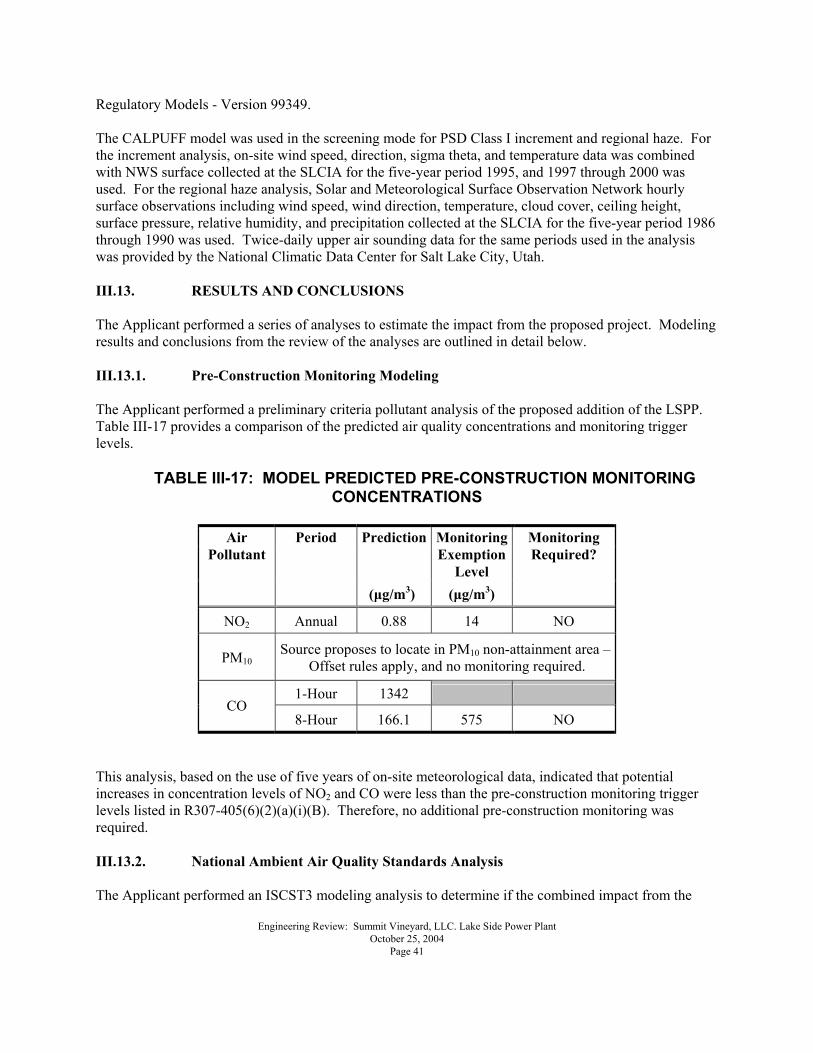
Engineering Review: Summit Vineyard, LLC. Lake Side Power Plant October 25, 2004 Page 41
Regulatory Models - Version 99349. The CALPUFF model was used in the screening mode for PSD Class I increment and regional haze. For the increment analysis, on-site wind speed, direction, sigma theta, and temperature data was combined with NWS surface collected at the SLCIA for the five-year period 1995, and 1997 through 2000 was used. For the regional haze analysis, Solar and Meteorological Surface Observation Network hourly surface observations including wind speed, wind direction, temperature, cloud cover, ceiling height, surface pressure, relative humidity, and precipitation collected at the SLCIA for the five-year period 1986 through 1990 was used. Twice-daily upper air sounding data for the same periods used in the analysis was provided by the National Climatic Data Center for Salt Lake City, Utah. III.13. RESULTS AND CONCLUSIONS The Applicant performed a series of analyses to estimate the impact from the proposed project. Modeling results and conclusions from the review of the analyses are outlined in detail below. III.13.1. Pre-Construction Monitoring Modeling The Applicant performed a preliminary criteria pollutant analysis of the proposed addition of the LSPP. Table III-17 provides a comparison of the predicted air quality concentrations and monitoring trigger levels.
TABLE III-17: MODEL PREDICTED PRE-CONSTRUCTION MONITORING CONCENTRATIONS
Prediction Monitoring
Exemption Level
Air Pollutant
Period
(µg/m3) (µg/m3)
Monitoring Required?
NO2 Annual 0.88 14 NO
PM10 Source proposes to locate in PM10 non-attainment area �
Offset rules apply, and no monitoring required.
1-Hour 1342 CO
8-Hour 166.1 575 NO This analysis, based on the use of five years of on-site meteorological data, indicated that potential increases in concentration levels of NO2 and CO were less than the pre-construction monitoring trigger levels listed in R307-405(6)(2)(a)(i)(B). Therefore, no additional pre-construction monitoring was required. III.13.2. National Ambient Air Quality Standards Analysis The Applicant performed an ISCST3 modeling analysis to determine if the combined impact from the
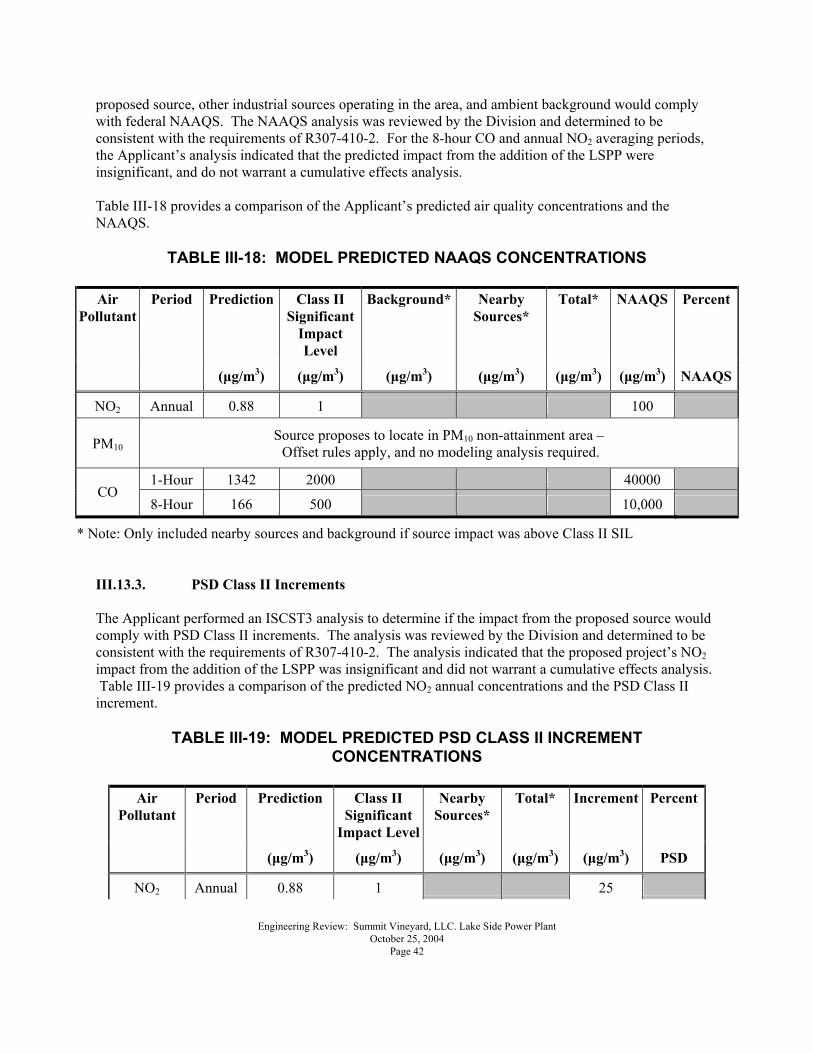
Engineering Review: Summit Vineyard, LLC. Lake Side Power Plant October 25, 2004 Page 42
proposed source, other industrial sources operating in the area, and ambient background would comply with federal NAAQS. The NAAQS analysis was reviewed by the Division and determined to be consistent with the requirements of R307-410-2. For the 8-hour CO and annual NO2 averaging periods, the Applicant�s analysis indicated that the predicted impact from the addition of the LSPP were insignificant, and do not warrant a cumulative effects analysis. Table III-18 provides a comparison of the Applicant�s predicted air quality concentrations and the NAAQS.
TABLE III-18: MODEL PREDICTED NAAQS CONCENTRATIONS
Prediction Class II Significant
Impact Level
Background* Nearby Sources*
Total* NAAQS Percent Air Pollutant
Period
(µg/m3) (µg/m3) (µg/m3) (µg/m3) (µg/m3) (µg/m3) NAAQS
NO2 Annual 0.88 1 100
PM10 Source proposes to locate in PM10 non-attainment area � Offset rules apply, and no modeling analysis required.
1-Hour 1342 2000 40000 CO
8-Hour 166 500 10,000
* Note: Only included nearby sources and background if source impact was above Class II SIL III.13.3. PSD Class II Increments The Applicant performed an ISCST3 analysis to determine if the impact from the proposed source would comply with PSD Class II increments. The analysis was reviewed by the Division and determined to be consistent with the requirements of R307-410-2. The analysis indicated that the proposed project�s NO2 impact from the addition of the LSPP was insignificant and did not warrant a cumulative effects analysis. Table III-19 provides a comparison of the predicted NO2 annual concentrations and the PSD Class II increment.
TABLE III-19: MODEL PREDICTED PSD CLASS II INCREMENT CONCENTRATIONS
Prediction Class II
Significant Impact Level
Nearby Sources*
Total* Increment PercentAir Pollutant
Period
(µg/m3) (µg/m3) (µg/m3) (µg/m3) (µg/m3) PSD
NO2 Annual 0.88 1 25
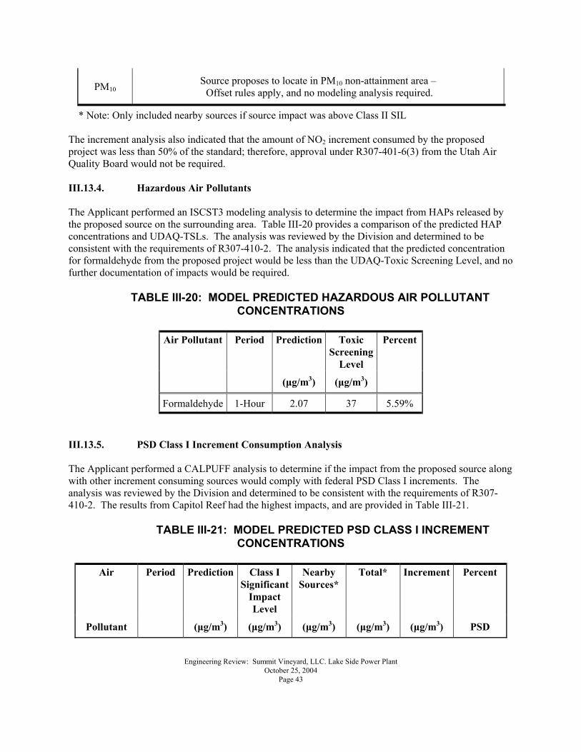
Engineering Review: Summit Vineyard, LLC. Lake Side Power Plant October 25, 2004 Page 43
PM10 Source proposes to locate in PM10 non-attainment area � Offset rules apply, and no modeling analysis required.
* Note: Only included nearby sources if source impact was above Class II SIL The increment analysis also indicated that the amount of NO2 increment consumed by the proposed project was less than 50% of the standard; therefore, approval under R307-401-6(3) from the Utah Air Quality Board would not be required. III.13.4. Hazardous Air Pollutants The Applicant performed an ISCST3 modeling analysis to determine the impact from HAPs released by the proposed source on the surrounding area. Table III-20 provides a comparison of the predicted HAP concentrations and UDAQ-TSLs. The analysis was reviewed by the Division and determined to be consistent with the requirements of R307-410-2. The analysis indicated that the predicted concentration for formaldehyde from the proposed project would be less than the UDAQ-Toxic Screening Level, and no further documentation of impacts would be required.
TABLE III-20: MODEL PREDICTED HAZARDOUS AIR POLLUTANT CONCENTRATIONS
Prediction Toxic
Screening Level
Percent Air Pollutant Period
(µg/m3) (µg/m3)
Formaldehyde 1-Hour 2.07 37 5.59% III.13.5. PSD Class I Increment Consumption Analysis The Applicant performed a CALPUFF analysis to determine if the impact from the proposed source along with other increment consuming sources would comply with federal PSD Class I increments. The analysis was reviewed by the Division and determined to be consistent with the requirements of R307-410-2. The results from Capitol Reef had the highest impacts, and are provided in Table III-21.
TABLE III-21: MODEL PREDICTED PSD CLASS I INCREMENT CONCENTRATIONS
Air Prediction Class I
Significant Impact Level
Nearby Sources*
Total* Increment Percent
Pollutant
Period
(µg/m3) (µg/m3) (µg/m3) (µg/m3) (µg/m3) PSD
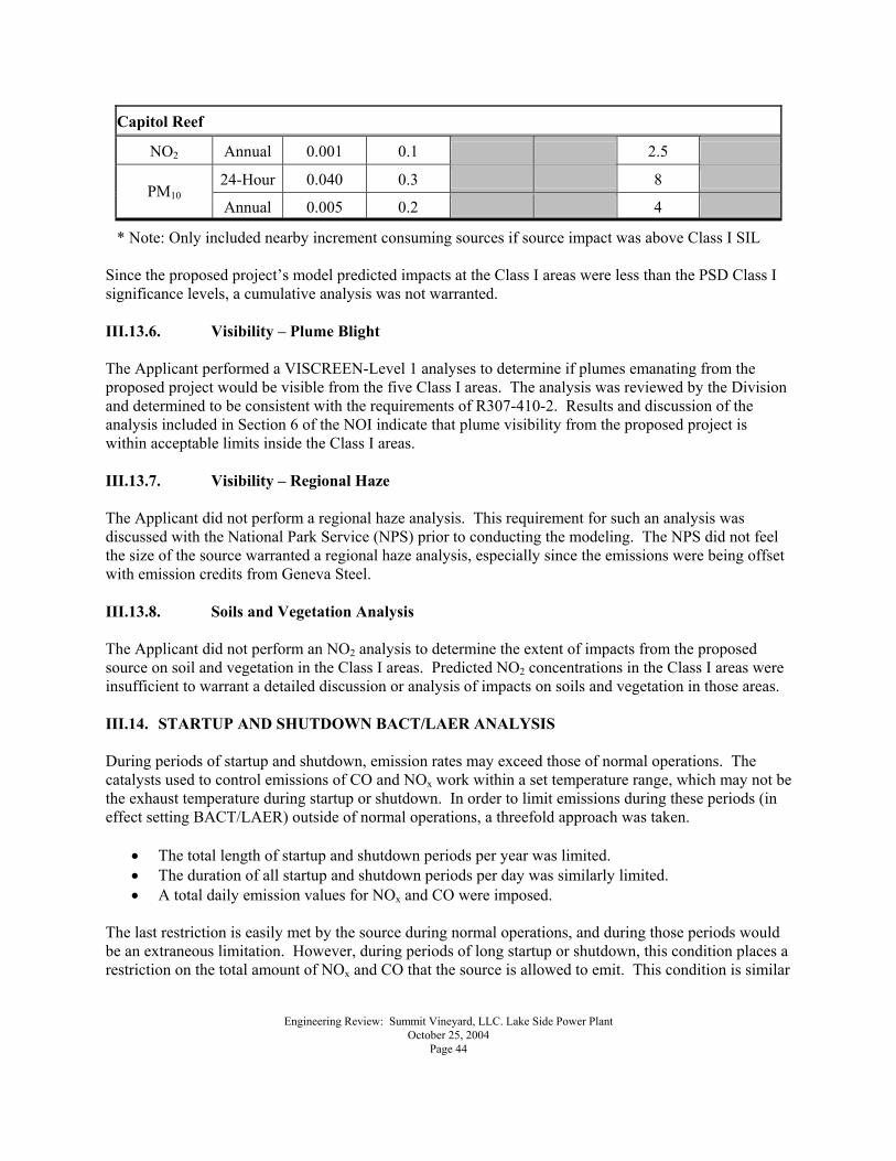
Engineering Review: Summit Vineyard, LLC. Lake Side Power Plant October 25, 2004 Page 44
Capitol Reef
NO2 Annual 0.001 0.1 2.5
24-Hour 0.040 0.3 8 PM10
Annual 0.005 0.2 4
* Note: Only included nearby increment consuming sources if source impact was above Class I SIL Since the proposed project�s model predicted impacts at the Class I areas were less than the PSD Class I significance levels, a cumulative analysis was not warranted. III.13.6. Visibility � Plume Blight The Applicant performed a VISCREEN-Level 1 analyses to determine if plumes emanating from the proposed project would be visible from the five Class I areas. The analysis was reviewed by the Division and determined to be consistent with the requirements of R307-410-2. Results and discussion of the analysis included in Section 6 of the NOI indicate that plume visibility from the proposed project is within acceptable limits inside the Class I areas. III.13.7. Visibility � Regional Haze The Applicant did not perform a regional haze analysis. This requirement for such an analysis was discussed with the National Park Service (NPS) prior to conducting the modeling. The NPS did not feel the size of the source warranted a regional haze analysis, especially since the emissions were being offset with emission credits from Geneva Steel. III.13.8. Soils and Vegetation Analysis The Applicant did not perform an NO2 analysis to determine the extent of impacts from the proposed source on soil and vegetation in the Class I areas. Predicted NO2 concentrations in the Class I areas were insufficient to warrant a detailed discussion or analysis of impacts on soils and vegetation in those areas. III.14. STARTUP AND SHUTDOWN BACT/LAER ANALYSIS During periods of startup and shutdown, emission rates may exceed those of normal operations. The catalysts used to control emissions of CO and NOx work within a set temperature range, which may not be the exhaust temperature during startup or shutdown. In order to limit emissions during these periods (in effect setting BACT/LAER) outside of normal operations, a threefold approach was taken.
• The total length of startup and shutdown periods per year was limited. • The duration of all startup and shutdown periods per day was similarly limited. • A total daily emission values for NOx and CO were imposed.
The last restriction is easily met by the source during normal operations, and during those periods would be an extraneous limitation. However, during periods of long startup or shutdown, this condition places a restriction on the total amount of NOx and CO that the source is allowed to emit. This condition is similar
Engineering Review: Summit Vineyard, LLC. Lake Side Power Plant October 25, 2004 Page 45
to those being imposed on similar sources elsewhere in the country. These conditions are as follows:
• Total yearly hours of startup and shutdown operations = 613.5 hours/year • Total daily hours of startup and shutdown operations = 14 hours/day • Total daily emissions of NOx = 744 lbs/day • Total daily emissions of CO = 9,182 lbs/day
III.15. ALTERNATIVE SITES ANALYSIS This analysis is intended to comply with the requirements of Utah Administrative Code section R307-401-8, nonattainment and maintenance areas. This regulation requires an owner or operator of a major new stationary source of air emissions or a source undergoing a major modification affecting its air emissions to analyze alternative sites, sizes, production processes, and environmental control techniques if the proposed project is located in an area that is not in attainment of National Ambient Air Quality Standards (NAAQS). The required analysis is intended to identify the environmental and social costs of the proposed project and compare them to the overall benefits of the project. This analysis must demonstrate that the benefits of the expansion significantly outweigh the environmental and social costs. III.15.1 Project Objectives The need for the new facility is a result of a significant increase in the electrical demand of the Salt Lake Valley, specifically during the hot summer months. The Salt Lake Valley is �line limited�; electrical transmission lines into the Salt Lake Valley from distant power plants are operating at capacity and are incapable of carrying the additional power. It is necessary to provide generation near load centers for ancillary services such as voltage support as well as to provide generation in a time efficient manner. It is intended that this generation act as a hedge against high prices for independent operators in the Utah area as well as providing voltage support. III.15.2 Dismissed Alternative Sites The following alternative sites were considered and rejected:
• Elberta: Elberta is the future location of Questar�s 104 natural gas pipeline expansion tie-in to the Kern River Pipeline. Therefore, natural gas would be readily available. However, greenfield site development would be required prior to plant construction. Only 345 kV transmission is available. Water supply would be a problem for short-term development. Distance from load centers would result in less voltage support benefits.
• Kennecott North: The existing Kennecott power facility would readily enable a transmission interconnection. The natural gas supply would be adequate if Kennecott were to curtail power production from natural gas. This option would be viable, but Kennecott is not interested in a joint development in this type of project.
• Kennecott South:
Engineering Review: Summit Vineyard, LLC. Lake Side Power Plant October 25, 2004 Page 46
Locating a plant neat the Copper Mine would offer sufficient transmission access and load, but natural gas availability is inadequate. With an expanded natural gas connection, this option would be viable, but Kennecott is not interested in a joint development at the current time.
• Central and Southern Utah: Location of the additional generation at other existing plants in Carbon and Emery counties was not seriously considered for a number of reasons. Natural gas and water availability are questionable. Altitudes over 6,000 feet would impact plant output and performance. Additionally, the distance from the Salt Lake Valley would considerably reduce the voltage support benefit. III.15.3 Chosen Site
• Geneva Steel Location: This location is adequately serviced by electrical transmission lines, and it is proximate to both 138 kV and 345 kV connections. Natural gas availability was formerly questionable due to Geneva�s operational use of the fuel, but is greatly improved with both the permanent shut down of steel operations, and available tie-ins to the nearby Kern River Pipeline. Water availability is good, and altitudes are less than 6000 feet. Geneva Steel has both the available land and the emission offset credits available for this project. As the location is already zoned for heavy industrial use, and is in fact located on the former site of the steel mill, noise, equipment access, truck use, and other social issues are extremely limited. IV. APPLICABILITY OF FEDERAL REGULATIONS AND UTAH ADMINISTRATIVE CODES (UAC) The Notice of Intent submitted is for a new source. At the time of this review the Utah Administrative Code Rules 307 (UAC R307) and federal regulations have been examined to determine their applicability to this Notice of Intent. The following rules have been specifically addressed.
1. R307-101-2, Major Modification - means any physical change in or change in the method of operation of a major source that would result in a significant net emissions increase of any pollutant.
2. R307-107, UAC - Unavoidable breakdown reporting requirements
3. R307-150 Series, UAC - Inventories, Testing and Monitoring. These rules cover
emission inventory reporting requirements and require the owner or operator of sources of air pollution to submit an emissions inventory report:
R307-150. Emission Inventories R307-155. Hazardous Air Pollutant R307-158. Emission Statement Inventory.
4. R307-201-1(2), UAC - 20% maximum opacity limitation at all emission points. Visible
Engineering Review: Summit Vineyard, LLC. Lake Side Power Plant October 25, 2004 Page 47
emissions from installations constructed after April 25, 1971, except internal combustion engines, or any incinerator shall be of a shade or density no darker than 20% opacity, except as otherwise provided in these regulations.
5. R307-201-1(9), UAC - Opacity Observation.
6. R307-203-1(1), UAC - Commercial and Industrial Sources. Any coal, oil, or mixture
thereof, burned in any fuel burning or process installation not covered by New Source Performance Standards for sulfur emissions shall contain no more than 1.0 pound sulfur per million gross Btu heat input for any mixture of coal nor .85 pounds sulfur per million gross Btu heat input for any oil.
7. R307-205 (UAC) - Emission Standards: Fugitive Emissions and Fugitive Dust.
8. R307-206, UAC - Abrasive Blasting Requirements - Opacity limitations and performance
standards for abrasive blasting.
9. R307-305-5(1), UAC - Existing sources located in or affecting areas of non-attainment shall use reasonably available control measures to the extent necessary to insure the attainment and maintenance of the National Ambient Air Quality Standards (NAAQS).
10. R307-325-1(1) R307-325 applies to all sources in R307-326 through 341, major sources
as defined and outlined in section 182 of the Clean Air Act and non-major sources located in Davis and Salt Lake Counties and in any non-attainment area for ozone as defined in the State Implementation Plan.
11. R307-401-7, UAC - Rules for relocation of temporary sources.
12. R307-401-10(1), UAC - All sources excluding non-commercial residential dwellings
shall install oxides of nitrogen control/low oxides of nitrogen burners or controls resulting from application of an equivalent technology, as determined by the Executive Secretary, whenever existing fuel combustion burners are replaced, unless such replacement is not physically practical or cost effective. The request for an exemption shall be presented to the Executive Secretary for review and approval.
13. R307-403-3, UAC - Every major new source or major modification must be reviewed by
the Executive Secretary to determine if a source will cause or contribute to a violation of the NAAQS.
14. R307-403-5(1)(b), UAC - Enforceable offsets of 1.2:1 are required for new sources or
modifications that would produce an emission increase greater than or equal to 50 tons per year of any combination of PM10, SO2, and NOx.
15. R307-403-5(1)(c), UAC - Enforceable offsets of 1:1 are required for new sources or
modifications that would produce an emission increase greater than or equal to 25 tons per year but less than 50 tons per year of any combination of PM10, SO2, and NOx.
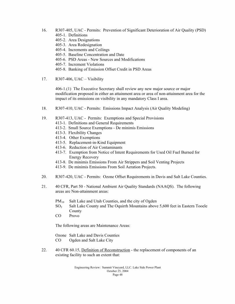
Engineering Review: Summit Vineyard, LLC. Lake Side Power Plant October 25, 2004 Page 48
16. R307-405, UAC - Permits: Prevention of Significant Deterioration of Air Quality (PSD) 405-1. Definitions 405-2. Area Designations 405-3. Area Redesignation 405-4. Increments and Ceilings 405-5. Baseline Concentration and Date 405-6. PSD Areas - New Sources and Modifications 405-7. Increment Violations 405-8. Banking of Emission Offset Credit in PSD Areas
17. R307-406, UAC � Visibility
406-1.(1) The Executive Secretary shall review any new major source or major modification proposed in either an attainment area or area of non-attainment area for the impact of its emissions on visibility in any mandatory Class I area.
18. R307-410, UAC - Permits: Emissions Impact Analysis (Air Quality Modeling)
19. R307-413, UAC - Permits: Exemptions and Special Provisions
413-1. Definitions and General Requirements 413-2. Small Source Exemptions - De minimis Emissions 413-3. Flexibility Changes 413-4. Other Exemptions 413-5. Replacement-in-Kind Equipment 413-6. Reduction of Air Contaminants 413-7. Exemption from Notice of Intent Requirements for Used Oil Fuel Burned for
Energy Recovery 413-8. De minimis Emissions From Air Strippers and Soil Venting Projects 413-9. De minimis Emissions From Soil Aeration Projects.
20. R307-420, UAC - Permits: Ozone Offset Requirements in Davis and Salt Lake Counties.
21. 40 CFR, Part 50 - National Ambient Air Quality Standards (NAAQS). The following
areas are Non-attainment areas:
PM10 Salt Lake and Utah Counties, and the city of Ogden SO2 Salt Lake County and The Oquirrh Mountains above 5,600 feet in Eastern Tooele
County CO Provo
The following areas are Maintenance Areas:
Ozone Salt Lake and Davis Counties CO Ogden and Salt Lake City
22. 40 CFR 60.15, Definition of Reconstruction - the replacement of components of an
existing facility to such an extent that:

Engineering Review: Summit Vineyard, LLC. Lake Side Power Plant October 25, 2004 Page 49
A. The fixed capital cost of the new components exceeds 50% of the fixed capital
cost that would be required to construct a comparable entirely new facility and
B. It is technologically and economically feasible to meet the applicable standards set forth in this part.
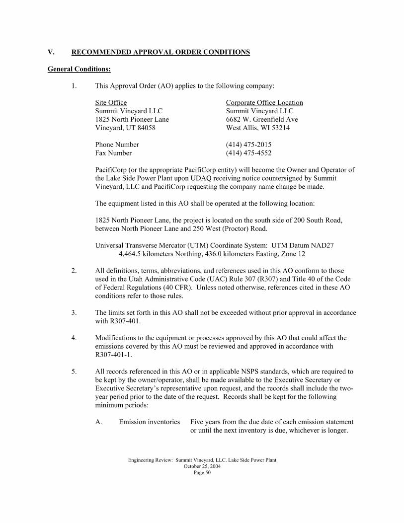
Engineering Review: Summit Vineyard, LLC. Lake Side Power Plant October 25, 2004 Page 50
V. RECOMMENDED APPROVAL ORDER CONDITIONS General Conditions:
1. This Approval Order (AO) applies to the following company:
Site Office Corporate Office Location Summit Vineyard LLC Summit Vineyard LLC 1825 North Pioneer Lane 6682 W. Greenfield Ave Vineyard, UT 84058 West Allis, WI 53214
Phone Number (414) 475-2015 Fax Number (414) 475-4552
PacifiCorp (or the appropriate PacifiCorp entity) will become the Owner and Operator of the Lake Side Power Plant upon UDAQ receiving notice countersigned by Summit Vineyard, LLC and PacifiCorp requesting the company name change be made. The equipment listed in this AO shall be operated at the following location: 1825 North Pioneer Lane, the project is located on the south side of 200 South Road, between North Pioneer Lane and 250 West (Proctor) Road.
Universal Transverse Mercator (UTM) Coordinate System: UTM Datum NAD27
4,464.5 kilometers Northing, 436.0 kilometers Easting, Zone 12
2. All definitions, terms, abbreviations, and references used in this AO conform to those used in the Utah Administrative Code (UAC) Rule 307 (R307) and Title 40 of the Code of Federal Regulations (40 CFR). Unless noted otherwise, references cited in these AO conditions refer to those rules.
3. The limits set forth in this AO shall not be exceeded without prior approval in accordance
with R307-401.
4. Modifications to the equipment or processes approved by this AO that could affect the emissions covered by this AO must be reviewed and approved in accordance with R307-401-1.
5. All records referenced in this AO or in applicable NSPS standards, which are required to
be kept by the owner/operator, shall be made available to the Executive Secretary or Executive Secretary�s representative upon request, and the records shall include the two-year period prior to the date of the request. Records shall be kept for the following minimum periods:
A. Emission inventories Five years from the due date of each emission statement
or until the next inventory is due, whichever is longer.
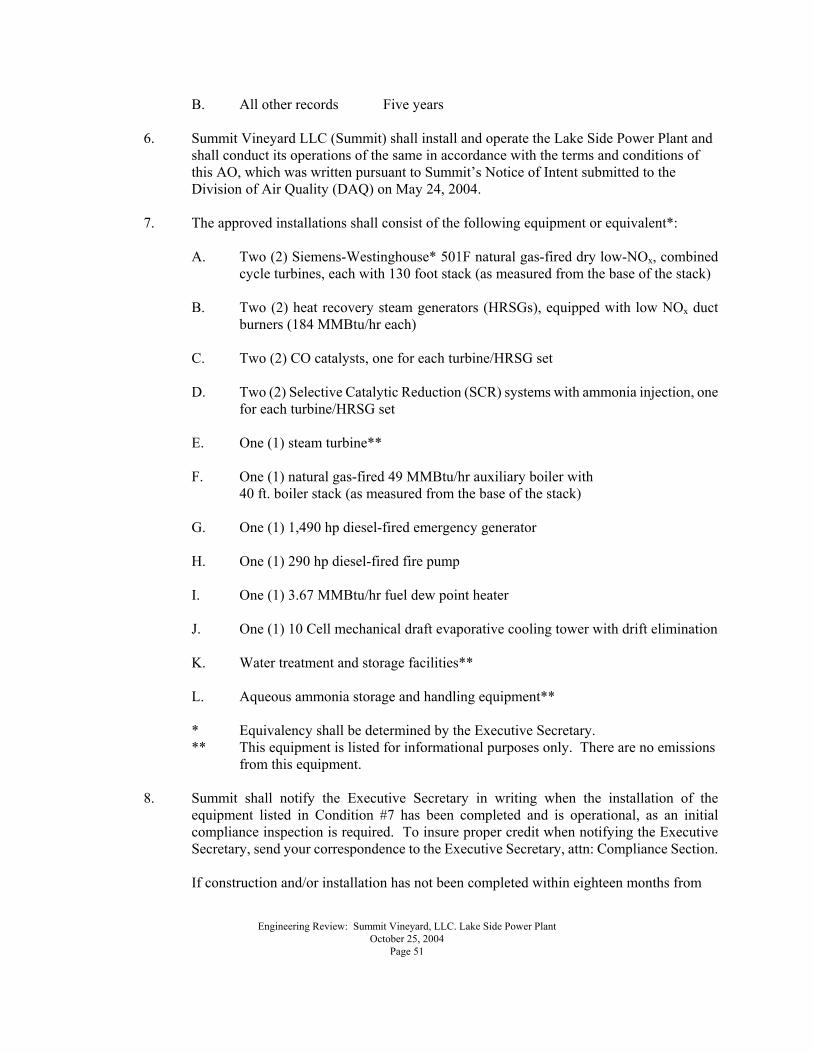
Engineering Review: Summit Vineyard, LLC. Lake Side Power Plant October 25, 2004 Page 51
B. All other records Five years
6. Summit Vineyard LLC (Summit) shall install and operate the Lake Side Power Plant and shall conduct its operations of the same in accordance with the terms and conditions of this AO, which was written pursuant to Summit�s Notice of Intent submitted to the Division of Air Quality (DAQ) on May 24, 2004.
7. The approved installations shall consist of the following equipment or equivalent*:
A. Two (2) Siemens-Westinghouse* 501F natural gas-fired dry low-NOx, combined
cycle turbines, each with 130 foot stack (as measured from the base of the stack) B. Two (2) heat recovery steam generators (HRSGs), equipped with low NOx duct
burners (184 MMBtu/hr each)
C. Two (2) CO catalysts, one for each turbine/HRSG set
D. Two (2) Selective Catalytic Reduction (SCR) systems with ammonia injection, one for each turbine/HRSG set
E. One (1) steam turbine**
F. One (1) natural gas-fired 49 MMBtu/hr auxiliary boiler with 40 ft. boiler stack (as measured from the base of the stack) G. One (1) 1,490 hp diesel-fired emergency generator
H. One (1) 290 hp diesel-fired fire pump
I. One (1) 3.67 MMBtu/hr fuel dew point heater
J. One (1) 10 Cell mechanical draft evaporative cooling tower with drift elimination
K. Water treatment and storage facilities**
L. Aqueous ammonia storage and handling equipment**
* Equivalency shall be determined by the Executive Secretary. ** This equipment is listed for informational purposes only. There are no emissions
from this equipment.
8. Summit shall notify the Executive Secretary in writing when the installation of the equipment listed in Condition #7 has been completed and is operational, as an initial compliance inspection is required. To insure proper credit when notifying the Executive Secretary, send your correspondence to the Executive Secretary, attn: Compliance Section.
If construction and/or installation has not been completed within eighteen months from
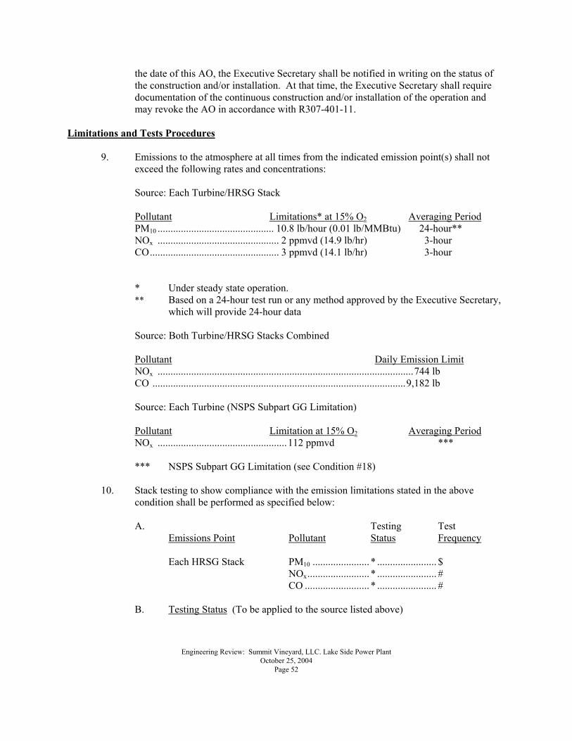
Engineering Review: Summit Vineyard, LLC. Lake Side Power Plant October 25, 2004 Page 52
the date of this AO, the Executive Secretary shall be notified in writing on the status of the construction and/or installation. At that time, the Executive Secretary shall require documentation of the continuous construction and/or installation of the operation and may revoke the AO in accordance with R307-401-11.
Limitations and Tests Procedures
9. Emissions to the atmosphere at all times from the indicated emission point(s) shall not exceed the following rates and concentrations:
Source: Each Turbine/HRSG Stack
Pollutant Limitations* at 15% O2 Averaging Period PM10 ............................................. 10.8 lb/hour (0.01 lb/MMBtu) 24-hour**
NOx ............................................... 2 ppmvd (14.9 lb/hr) 3-hour CO.................................................. 3 ppmvd (14.1 lb/hr) 3-hour
* Under steady state operation. ** Based on a 24-hour test run or any method approved by the Executive Secretary,
which will provide 24-hour data
Source: Both Turbine/HRSG Stacks Combined
Pollutant Daily Emission Limit NOx ...................................................................................................744 lb CO ..................................................................................................9,182 lb
Source: Each Turbine (NSPS Subpart GG Limitation)
Pollutant Limitation at 15% O2 Averaging Period NOx ..................................................112 ppmvd *** *** NSPS Subpart GG Limitation (see Condition #18)
10. Stack testing to show compliance with the emission limitations stated in the above
condition shall be performed as specified below:
A. Testing Test Emissions Point Pollutant Status Frequency
Each HRSG Stack PM10 ...................... * ....................... $
NOx........................ * ....................... # CO ......................... * ....................... #
B. Testing Status (To be applied to the source listed above)
Engineering Review: Summit Vineyard, LLC. Lake Side Power Plant October 25, 2004 Page 53
* Initial compliance testing is required. The initial test date shall be performed as soon as possible and in no case later than 180 days after the start up of a new emission source, an existing source without an AO, or the granting of an AO to an existing emission source that has not had an initial compliance test performed. If an existing source is modified, a compliance test is required on the modified emission point that has an emission rate limit.
$ Test every year or testing may be replaced with parametric monitoring if
approved by the Executive Secretary # Compliance shall be demonstrated through use of a Continuous
Emissions Monitoring System (CEM) as outlined in Conditions #14.A and #21 below. The Executive Secretary may require testing at any time.
C. Notification
The Executive Secretary shall be notified at least 30 days prior to conducting any required emission testing. A source test protocol shall be submitted to DAQ when the testing notification is submitted to the Executive Secretary.
The source test protocol shall be approved by the Executive Secretary prior to performing the test(s). The source test protocol shall outline the proposed test methodologies, stack to be tested, and procedures to be used. A pretest conference shall be held, if directed by the Executive Secretary.
D. Sample Location
The emission point shall be designed to conform to the requirements of 40 CFR 60, Appendix A, Method 1, or other methods as approved by the Administrator. An Occupational Safety and Health Administration (OSHA) or Mine Safety and Health Administration (MSHA) approved access shall be provided to the test location.
E. Volumetric Flow Rate
40 CFR 60, Appendix A, Method 2 or EPA Test Method No. 19 �SO2 Removal & PM, SO2, NOx Rates from Electric Utility Steam Generators� or other testing methods approved by the Administrator.
F. PM10
For stacks in which no liquid drops are present, the following methods shall be used: 40 CFR 51, Appendix M, Methods 201, 201a and 202, or other testing methods approved by the Administrator. All particulate captured shall be considered PM10. The back half condensibles shall be used for compliance demonstration as well as for inventory purposes.
Engineering Review: Summit Vineyard, LLC. Lake Side Power Plant October 25, 2004 Page 54
For stacks in which liquid drops are present, methods to eliminate the liquid drops should be explored. If no reasonable method to eliminate the drops exists, then the following methods shall be used: 40 CFR 60, Appendix A, Method 5, 5a, 5d, or 5e as appropriate, or other testing methods approved by the Administrator. The back half condensibles shall also be tested using the method specified by the Administrator. The portion of the front half of the catch considered PM10 shall be based on information in Appendix B of the fifth edition of the EPA document, AP-42, or other data acceptable to the Administrator.
G. Nitrogen Oxides (NOx)
40 CFR 60, Appendix A, Method 7, 7A, 7B, 7C, 7D, 7E, or other testing methods approved by the Administrator.
H. Carbon Monoxide (CO)
40 CFR 60, Appendix A, Method 10, or other testing methods approved by the Administrator.
I. Calculations
To determine mass emission rates (lb/hr, etc.) the pollutant concentration as determined by the appropriate methods above shall be multiplied by the volumetric flow rate and any necessary conversion factors determined by the Executive Secretary, to give the results in the specified units of the emission limitation.
11. Compliance with the 3-hour NOx and CO emission limitations specified in Condition #9
shall not be required during short-term excursions, limited to a cumulative total of 160 hours annually. Short-term excursions are defined as 15-minute periods designated by the Owner/Operator that are the direct result of transient load conditions, not to exceed four consecutive 15-minute periods, when the 15-minute average NOx and CO concentrations exceed 2.0 ppmv and 3.0 ppmv, dry @ 15% O2, respectively. Transient load conditions include the following: (1) Initiation/shutdown of combustion turbine inlet air-cooling (2) Rapid combustion turbine load changes (3) Initiation/shutdown of HRSG duct burners (4) Provision of Ancillary Services and Automatic Generation Control
During periods of transient load conditions, the NOx concentration shall not exceed 25 ppmv and the CO concentration shall not exceed 50 ppmv, dry @ 15% O2. All NOx and CO emissions during these events shall be included in all calculations of annual mass emissions as required by this permit.
12. Startup is defined as the period beginning with turbine initial firing until the unit meets
Engineering Review: Summit Vineyard, LLC. Lake Side Power Plant October 25, 2004 Page 55
the ppmvd emission limits in the first table of Condition #9 for steady state operation. Shutdown is defined as the period beginning with the initiation of turbine shutdown sequence and ending with the cessation of firing of the gas turbine engine. Startup and shutdown events shall not exceed 613.5 hours per turbine per calendar year and are counted toward the applicable annual emission limitations.
The total startup and shutdown period shall not exceed 14-hours in any one calendar day, commencing at midnight. Emissions during startup and shutdown periods must be counted toward the applicable annual emission limitations.
13. Visible emissions from the following emission points shall not exceed the following
values:
A. All natural gas combustion exhaust stacks - 10% opacity B. All other points - 20% opacity Opacity observations of emissions from stationary sources shall be conducted according to 40 CFR 60, Appendix A, Method 9.
14. The following limits shall not be exceeded:
Combined emissions of PM10+ NOx + SO2 shall not be greater than 260.9 tons per calendar year (from the plant-gas turbines, the duct burners, fire pump, auxiliary boiler, cooling tower and emergency generator)
Compliance with the above emission limitation for required offsets shall be determined as follows:
A. NOx from the gas turbine and the duct burner shall be obtained from CEMS recorded data
B PM10 from the gas turbine and the duct burner shall be obtained from the latest emission test record data
C. SO2 from the gas turbine and the duct burner shall be from the latest
emission test or if testing is not required by the other alternative method as approved by the Executive Secretary or Administrator.
D. NOx, PM10 and SO2 for auxiliary boiler, emergency generator, cooling tower
and fire pump shall be obtained from the U.S. EPA�s compilation of air pollutants emission factors, AP-42.
To determine compliance with the combined annual limit the owner/operator shall calculate average hourly rate (using CEMS recorded data as outlined in Condition #21, test results and AP-42 calculations) and sum them over calendar year.
15. Emergency generators shall be used for electricity producing operation only during the
Engineering Review: Summit Vineyard, LLC. Lake Side Power Plant October 25, 2004 Page 56
periods when electric power from the public utilities is interrupted, and for regular maintenance and testing. Records documenting generator usage shall be kept in a log and they shall show the date the generator was used, the duration in hours of the generator usage, and the reason for each generator usage.
Fuels
16. The owner/operator shall use natural gas as fuel in the combustion turbines, duct burners and auxiliary boiler.
17. The owner/operator shall use a combination of #2 fuel oil or diesel fuel in the emergency
generators and fire pump.
The sulfur content of any #2 fuel oil or diesel fuel burned shall not exceed 0.05 percent by weight. Sulfur content shall be determined by ASTM Method D-4294-89, or approved equivalent. Certification of fuels shall be either by the owner/operator�s own testing or test reports from the fuel marketer. For purposes of demonstrating compliance with this limitation, the owner/operator may obtain the above specifications by testing each purchase of fuel in accordance with the required methods; by inspection of the specifications provided by the vendor for each purchase of fuel; or by inspection of summary documentation of the fuel sulfur content from the vendor; provided that the above specifications are available from the vendor for each purchase if requested.
Federal Limitations and Requirements
18. In addition to the requirements of this AO, all applicable provisions of 40 CFR 60, New Source Performance Standards (NSPS) Subpart A, 40 CFR 60.1 to 60.18; Subpart GG, 40 CFR 60.330 to 60.334 (Standards of Performance for Stationary Gas Turbines); Subpart Db, 40 CFR 60.40b to 60.49b (Standards of Performance for Industrial-Commercial-Institutional Steam Generating Units); and Subpart Dc, 40 CFR 60.40c to 60.49c (Standards of Performance for Small Industrial-Commercial-Institutional Steam Generating Units) � apply to this installation as follows:
Subpart Db: Heat Recovery Steam Generators (HRSGs) Subpart Dc: Auxiliary Boiler Subpart GG: Combustion Turbines
19. In addition to the requirements of this AO, all applicable provisions of 40 CFR Part 72, 73,
75, 76, 77 and 78, Federal Regulations for the Acid Rain Program under Clean Air Act Title IV apply to this installation.
Monitoring - Continuous Emissions Monitoring
20. The owner/operator shall install, calibrate, maintain, and operate a continuous emissions monitoring system on each of the HRSG stacks. Summit shall record the output of the system, for measuring the NOx and CO emissions. The monitoring system shall comply with all applicable sections of R307-170; 40 CFR 13; and 40 CFR 60, Appendix B.
Engineering Review: Summit Vineyard, LLC. Lake Side Power Plant October 25, 2004 Page 57
All continuous emissions monitoring devices as required in federal regulations and state rules shall be installed and operational prior to placing the affected source in operation.
Except for system breakdown, repairs, calibration checks, and zero and span adjustments required under paragraph (d) 40 CFR 60.13, the owner/operator of an affected source shall continuously operate all required continuous monitoring systems and shall meet minimum frequency of operation requirements as outlined in 40 CFR 60.13 and Section R307-170.
Records & Miscellaneous
21. At all times, including periods of startup, shutdown, and malfunction, owners and operators shall, to the extent practicable, maintain and operate any equipment approved under this Approval Order including associated air pollution control equipment in a manner consistent with good air pollution control practice for minimizing emissions. Determination of whether acceptable operating and maintenance procedures are being used will be based on information available to the Executive Secretary which may include, but is not limited to, monitoring results, opacity observations, review of operating and maintenance procedures, and inspection of the source. All maintenance performed on equipment authorized by this AO shall be recorded.
22. The owner/operator shall comply with R307-150 Series. Inventories, Testing and
Monitoring.
23. The owner/operator shall comply with R307-107. General Requirements: Unavoidable Breakdowns.
The Executive Secretary shall be notified in writing if the company is sold or changes its name. Under R307-150-1, the Executive Secretary may require a source to submit an emission inventory for any full or partial year on reasonable notice. This AO in no way releases the owner or operator from any liability for compliance with all other applicable federal, state, and local regulations including R307. A copy of the rules, regulations and/or attachments addressed in this AO may be obtained by contacting the Division of Air Quality. The Utah Administrative Code R307 rules used by DAQ, the Notice of Intent (NOI) guide, and other air quality documents and forms may also be obtained on the Internet at the following web site: http://www.airquality.utah.gov/ The annual emissions estimations below are for the purpose of determining the applicability of Prevention of Significant Deterioration, non-attainment area, maintenance area, and Title V source requirements of the R307.
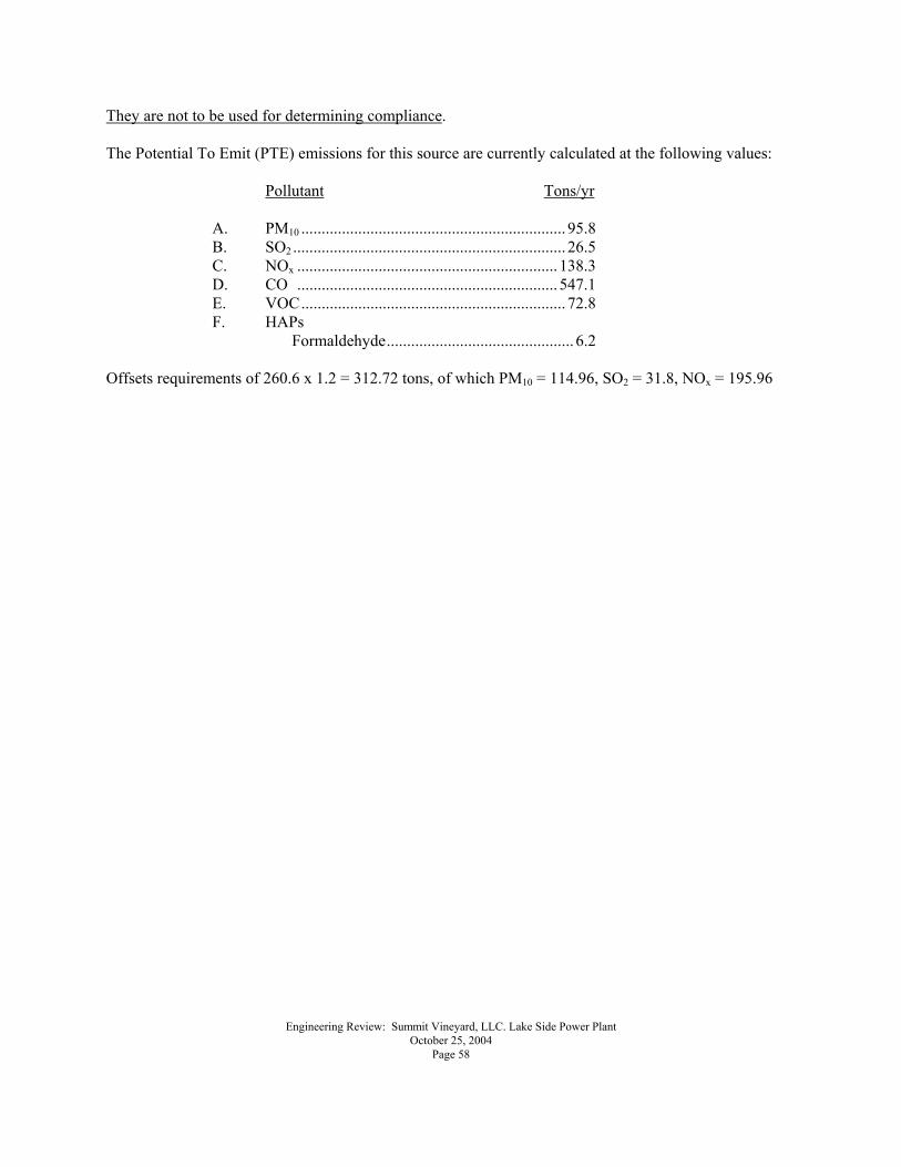
Engineering Review: Summit Vineyard, LLC. Lake Side Power Plant October 25, 2004 Page 58
They are not to be used for determining compliance. The Potential To Emit (PTE) emissions for this source are currently calculated at the following values:
Pollutant Tons/yr A. PM10 ................................................................. 95.8 B. SO2 ................................................................... 26.5 C. NOx ................................................................ 138.3 D. CO ................................................................ 547.1 E. VOC................................................................. 72.8 F. HAPs
Formaldehyde.............................................. 6.2 Offsets requirements of 260.6 x 1.2 = 312.72 tons, of which PM10 = 114.96, SO2 = 31.8, NOx = 195.96