Embed Size (px)
DESCRIPTION
USPV Architecture User Guide
Citation preview
MK-96RD635-01
Hitachi Universal Storage Platform V User and Reference Guide
FASTFIND LINKS
Document Organization
Product Version
Getting Help
Contents

ii
Hitachi Universal Storage Platform V User and Reference Guide
Copyright © 2007 Hitachi Data Systems Corporation, ALL RIGHTS RESERVED
Notice: No part of this publication may be reproduced or transmitted in any form or by any means, electronic or mechanical, including photocopying and recording, or stored in a database or retrieval system for any purpose without the express written permission of Hitachi Data Systems Corporation (hereinafter referred to as “Hitachi Data Systems”).
Hitachi Data Systems reserves the right to make changes to this document at any time without notice and assumes no responsibility for its use. Hitachi Data Systems products and services can only be ordered under the terms and conditions of Hitachi Data Systems’ applicable agreements. All of the features described in this document may not be currently available. Refer to the most recent product announcement or contact your local Hitachi Data Systems sales office for information on feature and product availability.
This document contains the most current information available at the time of publication. When new and/or revised information becomes available, this entire document will be updated and distributed to all registered users.
Hitachi Data Systems is a registered trademark and service mark of Hitachi, Ltd., and the Hitachi Data Systems design mark is a trademark and service mark of Hitachi, Ltd.
Hitachi Data Systems is a registered trademark and service mark of Hitachi , Ltd., and the Hitachi Data Systems design mark is a trademark and service mark of Hitachi , Ltd. HiCommand is a trademark of Hitachi , Ltd.
All other brand or product names are or may be trademarks or service marks of and are used to identify products or services of their respective owners.

Contents iii
Hitachi Universal Storage Platform V User and Reference Guide
Contents
Preface..................................................................................................vii
Overview of the Universal Storage Platform V ......................................... 1-1
Key Features of the Universal Storage Platform V ................................................1-2 Continuous Data Availability ........................................................................1-3 Connectivity ...............................................................................................1-4 Mainframe Compatibility and Functionality ....................................................1-5 Open-Systems Compatibility and Functionality ..............................................1-6 Hitachi NAS Blade.......................................................................................1-7 SAN Solutions and Open Storage Networks...................................................1-9 Program Products and Software Products ...................................................1-10 Storage Subsystem Scalability....................................................................1-13
Reliability, Availability, and Serviceability ...........................................................1-14
Subsystem Architecture and Components ............................................... 2-1
Overview..........................................................................................................2-2 Hardware Architecture.......................................................................................2-4 Components of the Controller Frame...................................................................2-5
Storage Clusters .........................................................................................2-5 Nonvolatile Shared Memory .........................................................................2-6 Nonvolatile Cache Memory ..........................................................................2-6 Multiple Data and Control Paths ...................................................................2-7 Redundant Power Supplies ..........................................................................2-8 Channel Adapters and Front-End Directors....................................................2-8 Host Channels ..........................................................................................2-10 Disk Adapters and Back-End Directors ........................................................2-12
Components of the Array Frame.......................................................................2-15 Hard Disk Drives.......................................................................................2-15 Array Groups............................................................................................2-17 Sequential Data Striping............................................................................2-20 LDEV Striping Across Array Groups.............................................................2-20

iv Contents
Hitachi Universal Storage Platform V User and Reference Guide
Intermix Configurations................................................................................... 2-24 RAID-Level Intermix................................................................................. 2-24 Hard Disk Drive Intermix .......................................................................... 2-25 Device Emulation Intermix........................................................................ 2-25
Service Processor (SVP) .................................................................................. 2-26 Storage Navigator........................................................................................... 2-27
Functional and Operational Characteristics ............................................. 3-1
New Features and Capabilities of the Universal Storage Platform V ....................... 3-2 I/O Operations ................................................................................................. 3-3 Cache Management .......................................................................................... 3-4
Algorithms for Cache Control ...................................................................... 3-4 Write Pending Rate .................................................................................... 3-4
Control Unit (CU) Images, LVIs, and LUs ............................................................ 3-6 CU Images ................................................................................................ 3-6 Logical Volume Image (LVIs) ...................................................................... 3-6 Logical Unit (LU) Type................................................................................ 3-6
System Option Modes ....................................................................................... 3-8 Open Systems Features and Functions ............................................................. 3-17 Open-Systems Configuration ........................................................................... 3-17
Configuring the Fibre-Channel Ports .......................................................... 3-18 Virtual LVI/LUN Devices............................................................................ 3-19 LUN Expansion (LUSE) Devices ................................................................. 3-19 Modes and Mode Options for Host Groups and iSCSI Targets....................... 3-19 Failover and SNMP Support....................................................................... 3-19 Share-Everything Architecture................................................................... 3-20
Data Management Functions ........................................................................... 3-21 Data Replication and Migration.................................................................. 3-23
Hitachi TrueCopy............................................................................... 3-23 Hitachi TrueCopy for z/OS.................................................................. 3-23 Hitachi ShadowImage....................................................................... 3-24 Hitachi ShadowImage for z/OS .......................................................... 3-24 Command Control Interface (CCI)....................................................... 3-25 Universal Replicator, Universal Replicator for z/OS ............................... 3-25 Copy-on-Write Snapshot .................................................................... 3-26 Compatible Replication for IBM XRC.................................................... 3-26
Backup/Restore and Sharing ..................................................................... 3-27 Cross-OS File Exchange ..................................................................... 3-27
Resource Management ............................................................................. 3-28 Universal Volume Manager ................................................................. 3-28 Virtual Partition Manager.................................................................... 3-28 LUN Manager .................................................................................... 3-28 LUN Expansion (LUSE)....................................................................... 3-29 Virtual LVI/LUN ................................................................................. 3-29

Contents v
Hitachi Universal Storage Platform V User and Reference Guide
Cache Residency Manager ..................................................................3-29 Cache Manager..................................................................................3-30 Compatible PAV .................................................................................3-30
Data Protection ........................................................................................3-31 LUN Security......................................................................................3-31 Volume Security.................................................................................3-31 Database Validator .............................................................................3-32 Data Retention Utility .........................................................................3-32 Volume Retention Manager .................................................................3-33 Volume Shredder ...............................................................................3-33
Performance Management.........................................................................3-34 Hitachi Performance Monitor ..............................................................3-34 Volume Migration...............................................................................3-34 Server Priority Manager ......................................................................3-34
Server-Based Software for ...............................................................................3-35 Hitachi Dynamic Link Manager (HDLM)......................................................3-36 HiCommand Device Manager .....................................................................3-36 HiCommand Provisioning Manager .............................................................3-37 Business Continuity Manager .....................................................................3-37 HiCommand Replication Monitor ................................................................3-38 HiCommand Tuning Manager.....................................................................3-38 HiCommand Protection Manager ................................................................3-40 HiCommand Tiered Storage Manager .........................................................3-40 Copy Manager for TPF ..............................................................................3-41 Dataset Replication for z/OS ......................................................................3-41
Planning for Installation and Operation .................................................. 4-1
User Responsibilities and Safety Precautions........................................................4-3 Safety Precautions ......................................................................................4-3
Dimensions, Physical Specifications, and Weight ..................................................4-4 Service Clearance, Floor Cutout, and Floor Load Rating Requirements ...................4-7 Electrical Specifications and Requirements for Three-Phase Subsystems ..............4-14
Power Plugs for Three-Phase (Europe) .......................................................4-15 Power Plugs for Three-Phase (USA) ...........................................................4-17 Features for Three-Phase ..........................................................................4-19 Power Cables and Connectors for Three-Phase............................................4-19 Input Voltage Tolerances for Three-Phase ..................................................4-20 Cable Dimensions for 50-Hz Three-Phase Subsystems .................................4-20
Electrical Specifications and Requirements for Single-Phase Subsystems ..............4-22 Power Plugs for Single-Phase (Europe) .......................................................4-23 Power Plugs for Single-Phase (USA) ...........................................................4-25 Features for Single-Phase..........................................................................4-27 Power Cables and Connectors for Single-Phase ...........................................4-27 Input Voltage Tolerances for Single-Phase ..................................................4-29

vi Contents
Hitachi Universal Storage Platform V User and Reference Guide
Cable Dimensions for 50-Hz Single-Phase Subsystems ................................ 4-29 Cable Requirements........................................................................................ 4-30
Device Interface Cable ............................................................................. 4-32 External Cable Length Between Units ........................................................ 4-33
Channel Specifications and Requirements ......................................................... 4-34 Environmental Specifications and Requirements ................................................ 4-37
Temperature, Humidity, and Altitude Requirements .................................... 4-37 Power Consumption and Heat Output Specifications ................................... 4-38 Loudness ................................................................................................ 4-41 Air Flow Requirements ............................................................................. 4-41 Vibration and Shock Tolerances................................................................. 4-42
Control Panel ................................................................................................. 4-42 Emergency Power-Off (EPO) ..................................................................... 4-45
Open-Systems Operations ............................................................................... 4-45 Command Tag Queuing............................................................................ 4-45 Host/Application Failover Support.............................................................. 4-45 Path Failover Support ............................................................................... 4-46 SIM Reporting ......................................................................................... 4-46 SNMP Remote Subsystem Management ..................................................... 4-47
Troubleshooting ................................................................................... 5-1
Troubleshooting ............................................................................................... 5-2 Calling the Hitachi Data Systems Support Center................................................. 5-3 Service Information Messages (SIMs)................................................................. 5-4
Units and Unit Conversions ................................................................... A-1
Acronyms and Abbreviations ..................................................... Acronyms-1
Index ............................................................................................ Index-1

Preface vii
Hitachi Universal Storage Platform V User and Reference Guide
Preface
This document provides the installation and configuration planning information for the Hitachi Universal Storage Platform V (USP V) disk subsystem, describes the physical, functional, and operational characteristics of the USP V, and provides general instructions for operating the USP V.
Please read this document carefully to understand how to use this product, and maintain a copy for reference purposes.
This preface includes the following information:
Intended Audience
Product Version
Document Revision Level
Changes in this Revision
Document Organization
Referenced Documents
Document Conventions
Convention for Storage Capacity Values
Getting Help
Comments
Notice: The use of Hitachi Universal Storage Platform V (USP V) and all other Hitachi Data Systems products is governed by the terms of your agreement(s) with Hitachi Data Systems.

viii Preface
Hitachi Universal Storage Platform V User and Reference Guide
Intended Audience
This document is intended for system administrators, Hitachi Data Systems representatives, and Authorized Service Providers who are involved in installing, configuring, and operating the Hitachi Universal Storage Platform V storage system.
This document assumes the following:
• The user has a background in data processing and understands RAID storage systems and their basic functions.
• The user is familiar with the open-system platforms and/or mainframe operating systems supported by the USP V. For details on supported host systems and platforms, please refer to the USP V Configuration Guide for the platform, or contact your Hitachi Data Systems account team.
• The user is familiar with the equipment used to connect RAID disk array subsystems to the supported host systems.
Product Version
This document revision applies to Universal Storage Platform V microcode 60-01-3x and higher.
Document Revision Level
Revision Date Description
MK-96RD635-P February 2007 Preliminary Release
MK-96RD635-00 February 2007 Initial Release, supersedes and replaces MK-96RD635-P
MK-96RD635-01 June 2007 Revision 1, supersedes and replaces MK-96RD635-00
Changes in this Revision
Not applicable to this release.
Preface ix
Hitachi Universal Storage Platform V User and Reference Guide
Document Organization
The following table provides an overview of the contents and organization of this document. Click the chapter title in the left column to go to that chapter. The first page of each chapter provides links to the sections in that chapter.
Chapter Description
Overview of the USP V This chapter provides an overview of the USP V, including features, benefits general function and connectivity descriptions.
Subsystem Artitecture and Components
This chapter describes the USP V architecture and components.
Functional and Operational Characteristics
This chapter discusses the functional and operational capabilities of the USP V.
Planning for Installation and Operation
This chapter provides information for planning and preparing a site before and during installation of the Hitachi USP V.
Troubleshooting This chapter provides troubleshooting guidelines and customer support contact information.
Acronyms and Abbreviations Defines the acronyms and abbreviations used in this document.
Index Lists the topics in this document in alphabetical order.
For further information on Hitachi Data Systems products and services, contact your Hitachi Data Systems account team, or visit Hitachi Data Systems online at http://www.hds.com.
Note: This document applies to all configurations and models of the Hitachi USP V (USP V) (for example, USP V100, USP V600, USP V1100).
Notice: The use of the USP V and all other Hitachi Data Systems products is governed by the terms of your agreement(s) with Hitachi Data Systems.
Referenced Documents
Hitachi Universal Storage Platform V:
Please see the following tables in this document for listings of the USP V user documentation:
• Software products: Table 3-5
• Host installation guides: Table 3-2
IBM® documentation:
• Planning for IBM Remote Copy, SG24-2595
• DFSMSdfp Storage Administrator Reference, SC28-4920
• DFSMS MVS V1 Remote Copy Guide and Reference, SC35-0169

x Preface
Hitachi Universal Storage Platform V User and Reference Guide
• OS/390 Advanced Copy Services, SC35-0395 (replaces Advanced Copy Services, SC35-0355)
• Storage Subsystem Library, 3990 Transaction Processing Facility Support RPQs, GA32-0134
• 3990 Operations and Recovery Guide, GA32-0253
• Storage Subsystem Library, 3990 Storage Control Reference for Model 6, GA32-0274

Preface xi
Hitachi Universal Storage Platform V User and Reference Guide
Document Conventions
The terms “Universal Storage Platform V” and “USP V” refer to all models of the Hitachi Universal Storage Platform V, unless otherwise noted.
This document uses the following typographic conventions:
Typographic Convention Description
Bold Indicates text on a window, other than the window title, including menus, menu options, buttons, fields, and labels. Example: Click OK.
Italic Indicates a variable, which is a placeholder for actual text provided by the user or system. Example: copy source-file target-file
Note: Angled brackets (< >) are also used to indicate variables.
screen/code Indicates text that is displayed on screen or entered by the user. Example: # pairdisplay -g oradb
< > angled brackets Indicates a variable, which is a placeholder for actual text provided by the user or system. Example: # pairdisplay -g <group>
Note: Italic font is also used to indicate variables.
[ ] square brackets Indicates optional values. Example: [ a | b ] indicates that you can choose a, b, or nothing.
{ } braces Indicates required or expected values. Example: { a | b } indicates that you must choose either a or b.
| vertical bar Indicates that you have a choice between two or more options or arguments. Examples:
[ a | b ] indicates that you can choose a, b, or nothing.
{ a | b } indicates that you must choose either a or b.
underline Indicates the default value. Example: [ a | b ]
This document uses the following icons to draw attention to information:
Icon Meaning Description
Note Calls attention to important and/or additional information.
Tip Provides helpful information, guidelines, or suggestions for performing tasks more effectively.
Caution Warns the user of adverse conditions and/or consequences (e.g., disruptive
operations).
WARNING Warns the user of severe conditions and/or consequences (e.g., destructive
operations).
DANGER Dangers provide information about how to avoid physical injury to yourself and
others.
ELECTRIC SHOCK HAZARD!
Warns the user of electric shock hazard. Failure to take appropriate precautions (e.g., do not touch) could result in serious injury.
ESD Sensitive Warns the user that the hardware is sensitive to electrostatic discharge (ESD).
Failure to take appropriate precautions (e.g., grounded wriststrap) could result in damage to the hardware.
xii Preface
Hitachi Universal Storage Platform V User and Reference Guide
Convention for Storage Capacity Values
Physical storage capacity values (e.g., disk drive capacity) are calculated based on the following values:
1 KB = 1,000 bytes 1 MB = 1,0002 bytes 1 GB = 1,0003 bytes 1 TB = 1,0004 bytes 1 PB = 1,0005 bytes
Logical storage capacity values (e.g., logical device capacity) are calculated based on the following values:
1 KB = 1,024 bytes 1 MB = 1,0242 bytes 1 GB = 1,0243 bytes 1 TB = 1,0244 bytes 1 PB = 1,0245 bytes 1 block = 512 bytes
Getting Help
If you need to call the Hitachi Data Systems Support Center, make sure to provide as much information about the problem as possible, including:
• The circumstances surrounding the error or failure.
• The exact content of any error message(s) displayed on the host system(s).
• The data in the CCI error log file and trace data (all files in the HORCM_LOG directory).
• The service information messages (SIMs), including reference codes and severity levels, displayed by Storage Navigator.
The Hitachi Data Systems customer support staff is available 24 hours/day, seven days a week. If you need technical support, please call:
• United States: (800) 446-0744
• Outside the United States: (858) 547-4526

Preface xiii
Hitachi Universal Storage Platform V User and Reference Guide
Comments
Please send us your comments on this document. Make sure to include the document title, number, and revision. Please refer to specific section(s) and paragraph(s) whenever possible.
• E-mail: [email protected]
• Fax: 858-695-1186
• Mail: Technical Writing, M/S 35-10 Hitachi Data Systems 10277 Scripps Ranch Blvd. San Diego, CA 92131
Thank you! (All comments become the property of Hitachi Data Systems Corporation.)

xiv Preface
Hitachi Universal Storage Platform V User and Reference Guide

1
Overview of the Universal Storage Platform V 1-1
Hitachi Universal Storage Platform V User and Reference Guide
Overview of the Universal Storage Platform V
This chapter provides an overview of the USP V, including features, benefits general function and connectivity descriptions.
Key Features of the Universal Storage Platform V
Reliability, Availability, and Serviceability

1-2 Overview of the Universal Storage Platform V
Hitachi Universal Storage Platform V User and Reference Guide
Key Features of the Universal Storage Platform V
The Hitachi Universal Storage Platform V (USP V) constitutes a new computing revolution that promises to deliver efficient and flexible IT infrastructure, breaking away from computing that is rigid and expensive and involves under-utilized resources. The USP V enables you to extend the life of current storage investments and take advantage of new functionality on yesterday’s storage products. Multiple and tiered heterogeneous storage systems can be connected to and managed through a unique new feature introduced on the USP V. Interoperability issues are eliminated and performance and capacity management is simplified to reduce overall storage costs. The USP V creates a data lifecycle management (DLM) foundation and enables massive consolidation and storage aggregation across disparate platforms.
The USP V is a multiplatform, high-performance, large-capacity storage array that provides high-speed response, continuous data availability, scalable connectivity, and expandable capacity in heterogeneous system environments. The USP V provides non-stop operation for 24×7 data centers and is compatible with industry-standard software. The advanced components, functions, and features of the USP V represent an innovative and integrated approach to DLM.
The USP V employs and improves upon the key characteristics of generations of successful Hitachi disk storage subsystems to achieve the highest level of performance and reliability currently available. The USP V features third-generation improvements to the Hi-Star™ crossbar switch architecture, the ground-breaking technology introduced and proven on previous-generation Hitachi storage arrays, as well as faster microprocessors on the front-end and back-end directors.
The USP V can operate with multi-host applications and host clusters, and is designed to handle very large databases as well as data warehousing and data mining applications that store and retrieve terabytes of data. The USP V supports an intermix of FICON®, ESCON®, fibre-channel, NAS, and iSCSI host attachment and can be configured for all-mainframe, all-open, and multiplatform operations.
The USP V provides many benefits and advantages as well as advanced new features for the user, including double or more scalability from the 9900V in both capacity and performance. The HiCommand™ licensed software products also support the USP V for maximum flexibility in configuration and management.

Overview of the Universal Storage Platform V 1-3
Hitachi Universal Storage Platform V User and Reference Guide
The Hitachi USP V is designed to meet customers’ evolving and increasing needs for data lifecycle management in the 21st century:
• Instant access to data around the clock:
– 100-percent data availability guarantee with no single point of failure
– Highly resilient multi-path fibre architecture
– Fully redundant, hot-swappable components and non-disruptive microcode updates
– Global dynamic hot sparing
– Duplexed write cache with battery backup
– Hi-Track® “call-home” maintenance system
– RAID-1, RAID-5, and/or RAID-6 array groups within the same subsystem
• Unmatched performance and capacity:
– Multiple point-to-point data and control paths
– Up to 68-GB/sec internal subsystem (data) bandwidth
– Fully addressable 256-GB data cache; separate control memory (up to 16 GB)
– Extremely fast and intelligent cache algorithms
– Non-disruptive expansion to over 332 TB raw capacity
– Simultaneous transfers from up to 64 separate hosts
– Up to 1152 high-throughput (10 or 15 krpm) fibre-channel, dual-active disk drives
• Extensive connectivity and resource sharing:
– Concurrent operation of UNIX®, Windows®, Linux®, and mainframe (z/OS®, S/390®) host systems
– FICON, Extended Serial Adapter® (ESCON), fibre-channel, NAS, and iSCSI server connections
– Fibre-channel switched, arbitrated loop, and point-to-point configurations
Continuous Data Availability
The Hitachi USP V is designed for nonstop operation and continuous access to all user data. To achieve nonstop customer operation, the USP V accommodates online feature upgrades and online software and hardware maintenance. Main components are implemented with a duplexed or redundant configuration. The USP V has no active single point of component failure.

1-4 Overview of the Universal Storage Platform V
Hitachi Universal Storage Platform V User and Reference Guide
Connectivity
The Hitachi USP V (USP V) RAID storage system supports concurrent attachment and support for all-mainframe, all-open, and multiplatform configurations using the following interface types:
• FICON. When FICON® channel interfaces are used, the USP V can provide up to 64 control unit (CU) images and 16,384 logical devices (LDEVs). Each physical FICON channel interface (port) supports up to 65,536 logical paths (1024 host paths × 64 CUs) for a maximum of 131,072 logical paths per USP V subsystem. FICON connection provides transfer rates of up to 400 MB/sec (4 Gbps).
• Hitachi Extended Serial Adapter™ (ExSA™) (compatible with ESCON protocol). When ExSA channel interfaces are used, the USP V can provide up to 64 control unit (CU) images and 16,384 logical devices (LDEVs). Each physical ExSA channel interface (port) supports up to 512 logical paths (32 host paths × 16 CUs) for a maximum of 32,768 logical paths per USP V subsystem. ExSA connection provides transfer rates of up to 17 MB/sec.
• Fibre-channel. When fibre-channel interfaces are used, the USP V can provide up to 192 ports for attachment to UNIX-based and/or PC-server platforms. The type of host platform determines the number of logical units (LUs) that may be connected to each port (maximum 1024 per port). Fibre-channel connection provides data transfer rates of up to 400 MB/sec (4 Gbps). The USP V supports fibre-channel arbitrated loop (FC-AL) and fabric fibre-channel topologies as well as high-availability (HA) fibre-channel configurations using hubs and switches.
• NAS. The USP V supports a maximum of 32 NAS channel interfaces. The NAS channel interface boards provide data transfer speeds of up to 100 MB/sec. The USP V supports shortwave (multimode) NAS channel adapters and can be located up to 500 meters (2750 feet) from the NAS-attached host(s).
• iSCSI. The USP V supports a maximum of 48 iSCSI interfaces. The iSCSI channel interface boards provide data transfer speeds of up to 100 MB/sec. The USP V supports shortwave (multimode) iSCSI channel adapters and can be located up to 500 meters (2750 feet) from the iSCSI-attached host(s).
Note: Current addressing limitations for ESCON interface are 1024 Unit Addresses (UA) per channel. With FICON interface, addressability is increased to 65,536.

Overview of the Universal Storage Platform V 1-5
Hitachi Universal Storage Platform V User and Reference Guide
Mainframe Compatibility and Functionality
The Hitachi USP V (USP V) supports 3990-6, 3990-6E, and 2105 control unit (CU) emulation types and can be configured with multiple concurrent logical volume image (LVI) formats, including 3390-3, 3390-3R, 3390-9, and larger. In addition to full System-Managed Storage (SMS) compatibility, the USP V also provides the following functionalities in the mainframe environment:
• Sequential data striping
• Cache fast write (CFW) and DASD fast write (DFW)
• Enhanced dynamic cache management
• Multiple Allegiance support
• Concurrent Copy (CC) support
• Peer-to-Peer Remote Copy (PPRC) and Extended Remote Copy (XRC) support
• FlashCopy support
• Enhanced CCW support
• Priority I/O queuing
• Parallel Access Volume (PAV) support
• Transaction Processing Facility (TPF)/Multi-Path Locking Facility (MPLF) support
• Support for Red Hat Linux for IBM S/390® and zSeries®
• Support for SuSE® Linux Enterprise Server (SLES) for IBM zSeries
For additional information on mainframe environments (e.g., CU types A-65A2, H-65A2, A-65C1, A-65C2), FICON connectivity, FICON/Open intermix configurations, and supported HBAs, switches, and directors (for example, McDATA®, CNT) for the USP V, please contact your Hitachi Data Systems account team.

1-6 Overview of the Universal Storage Platform V
Hitachi Universal Storage Platform V User and Reference Guide
Open-Systems Compatibility and Functionality
The Hitachi USP V supports multiple concurrent attachments to a variety of host operating systems (OS) and is compatible with most fibre-channel host bus adapters (HBAs). The number of logical units (LUs) that may be connected to each port is determined by the type of host platform being attached. The USP V currently supports the following platforms:
• Sun® Solaris®
• IBM AIX
• Note: The AIX® ODM updates are included on the Product Documentation Library (PDL) CDs that come with the Hitachi USP V (USP V).
• HP-UX
• HP® Tru64 UNIX
• HP OpenVMS
• SGI® IRIX®
• Microsoft® Windows 2000
• Microsoft Windows 2003
• Novell® NetWare®
• Red Hat Linux
• SuSE Linux
• VMware®
Contact Hitachi Data Systems for the latest information on platform, OS version, and HBA support.
The Hitachi USP V provides enhanced dynamic cache management and supports command tag queuing and multi-initiator I/O. Command tag queuing enables hosts to issue multiple disk commands to the fibre-channel adapter without having to serialize the operations. The USP V operates with industry-standard middleware products providing application/host failover, I/O path failover, and logical volume management. The USP V also supports the industry-standard simple network management protocol (SNMP) for remote subsystem management from the open-system host.
The USP V is configured with OPEN-V logical units (LUs).* Users can perform additional LUN configuration activities using the Virtual LVI/LUN and LUN Expansion (LUSE) features of the Hitachi Universal Storage Platform V.
*Note: For information on other LU types (for example, OPEN-3, OPEN-9), please contact your Hitachi Data Systems representative.
Overview of the Universal Storage Platform V 1-7
Hitachi Universal Storage Platform V User and Reference Guide
Hitachi NAS Blade
The Hitachi NAS Blade system provides a NAS environment based on NAS packages incorporated in the USP V. Clients (such as end users, application servers, and database servers) can access file systems on the disks over the NAS Blade packages installed on the USP V disk subsystem.
The main features of the NAS Blade system are:
• Open data-sharing environment that utilizes legacy systems
The disk subsystem enables integrated data management utilizing the enterprise’s LAN environment already in place. Data within a disk subsystem can be shared across heterogeneous platforms.
• High-performance NAS environment
The NAS Packages are built into the disk subsystem, so overhead is lower than with a separate NAS server and disk subsystem.
• High availability
In a NAS Blade system, NAS Packages make up a cluster system to reliably deliver services such as NFS and CIFS file shares provided by NAS functionality. If an error occurs in one NAS Package, services can be relocated to the other NAS Package in the cluster, ensuring service stability.
Services are quickly switched within a cluster using the shared cache of the USP V. Used in conjunction with the failover functionality, the NAS Blade system enables online maintenance of hardware, software, and the services provided by the NAS Blade system.
• Scalability
In a NAS Blade system, a cluster is configured as two NAS Packages. The system can be extended in multiples of two NAS Packages. The USP V can provide up to 16 NAS Blade ports, assuring scalability of the NAS environment.
• Safety assuredness (optional functionality)
In a NAS Blade system, data resources on disk subsystems can be protected from viruses by linking to a network scan server that scans for viruses.
• High reliability (optional functionality)
By using optional programs, you can protect critical organization data resources that are shared on a disk subsystem against loss or corruption.
By using NAS Backup Restore and ShadowImage of the USP V, you can obtain high-speed snapshots and online backup.
You can also create differential-data snapshots by using NAS Sync Image.
Moreover, by using NAS Backup Restore, CCI, and TrueCopy, you can use the remote copy functionality to duplicate, into a different cabinet, data in a file system that is shared in a NAS Blade system.

1-8 Overview of the Universal Storage Platform V
Hitachi Universal Storage Platform V User and Reference Guide
The NAS Blade Manager software enables the user to efficiently set up, operate, and control the NAS Blade system. Running under the NAS OS, the NAS Blade Manager program supports NAS Blade system setup, operating status monitoring, modification of system settings, error monitoring, and data backup and restoration. NAS Blade Manager functions can be accessed over a Web browser from any client.
In a NAS Blade system, the NAS environment is realized by installing the NAS OS and the requisite programs for NAS operation on the USP V. The NAS OS is equipped with NAS functionality and the following functionality required for NAS Blade Manager operations:
• CIFS server
• NFS server
• LVM
• HIXFS
• RAID driver
• Web server
• NTP client
• SNMP agent
• DNS client
• NIS client
• Failover
• Installer
Overview of the Universal Storage Platform V 1-9
Hitachi Universal Storage Platform V User and Reference Guide
SAN Solutions and Open Storage Networks
Hitachi Data Systems’ end-to-end SAN Solutions give you the freedom to locate storage wherever it makes the greatest business sense while protecting your investment in currently installed components. Made possible by the advent and proliferation of high-speed technologies, storage area networks (SANs) break the traditional server/storage bond and enable total connectivity. As a result, you can consolidate large storage pools shareable across the enterprise, centralize management, and dramatically improve storage utilization while reducing costs.
Hitachi Data Systems’ SAN Solutions enable you to increase data availability, counter spiraling information management costs, and take advantage of the speed and flexibility of SAN technology. In addition to supporting the Storage Networking Industry Association’s open-systems standards, HDS SAN Solutions reduce total cost of ownership by minimizing support costs and downtime, and optimizing server and storage configurations.
The benefits of Hitachi Data Systems’ SAN Solutions include:
• Server/storage subsystem scalability
• Improved information access
• Enhanced application/backup performance
• Increased resource manageability and reliability
• Higher availability
HDS’ Open Storage Network solutions address the challenge of open architecture and multiple platforms. Open Storage Networks is the focus of Hitachi’s long-term vision for offering businesses complete freedom of choice in establishing data-centric enterprise networks, encompassing storage, switches, servers, management software, protocols, services, and networks developed by Hitachi, our alliance partners, and third party providers. Open Storage Network solutions facilitate:
• Consolidation of server and storage resources
• Data sharing across the enterprise
• Centralized resource and data management
• Superior data security
• Increased availability and scalability
• Business continuity and disaster recovery
For further information on SAN Solutions and Open Storage Networks, please contact your Hitachi Data Systems account team, or visit Hitachi Data Systems online at www.hds.com.

1-10 Overview of the Universal Storage Platform V
Hitachi Universal Storage Platform V User and Reference Guide
Program Products and Software Products
The USP V provides many advanced features and functions that increase data accessibility, enable continuous user data access, and deliver enterprise-wide coverage of on-line data copy/relocation, data access/protection, and storage resource management. Hitachi Data Systems’ software solutions provide a full complement of industry-leading copy, availability, resource management, and exchange software to support business continuity, database backup/restore, application testing, and data mining.
Table 1-1 lists and describes the program products for the USP V.
Table 1-2 lists and describes the software for the USP V. This information was current at the time of publication of this document and is subject to change.
Table 1-1 Program Products
Function and Product Name Description
Hitachi TrueCopy Hitachi TrueCopy for z/OS
Enables the user to perform remote copy operations between Universal Storage Platform V (and 9900V/9900) systems in different locations. TrueCopy provides synchronous and asynchronous copy modes for open-system and mainframe data.
Hitachi ShadowImage Hitachi ShadowImage for z/OS
Allows the user to create internal copies of volumes for purposes such as application testing and offline backup. Can be used in conjunction with TrueCopy to maintain multiple copies of data at primary and secondary sites.
Hitachi FlashCopy Mirroring Provides compatibility with the IBM FlashCopy mainframe host software function, which performs server-based data replication for mainframe data.
Hitachi Command Control Interface
Enables open-system users to perform data replication and data protection operations by issuing commands from the host to the Universal Storage Platform V. The CCI software supports scripting and provides failover and mutual hot standby functionality in cooperation with host failover products.
Hitachi Universal Replicator
Hitachi Universal Replicator for z/OS
Provides a RAID storage-based hardware solution for disaster recovery which enables fast and accurate system recovery, particularly for large amounts of data which span multiple volumes. Using UR, you can configure and manage highly reliable data replication systems using journal volumes to reduce chances of suspension of copy operations.
Copy-on-Write Snapshot Provides ShadowImage functionality using less capacity of the disk subsystem and less time for processing than ShadowImage by using “virtual” secondary volumes. COW Snapshot is useful for copying and managing data in a short time with reduced cost. ShadowImage provides higher data integrity.
Hitachi Compatible Replication for IBM XRC
Provides compatibility with the IBM Extended Remote Copy (XRC) mainframe host software function, which performs server-based asynchronous remote copy operations for mainframe LVIs.
Hitachi Cross-OS File Exchange Enables users to transfer data between mainframe and open-system platforms using the FICON and/or ExSA channels, which provides high-speed data transfer without requiring network communication links or tape.
Hitachi Code Converter

Overview of the Universal Storage Platform V 1-11
Hitachi Universal Storage Platform V User and Reference Guide
Function and Product Name Description
Hitachi Universal Volume Manager
Realizes the virtualization of the storage subsystem. Users can connect other subsystems to the Universal Storage Platform V and access the data on the external subsystem over virtual devices on the USP V. Functions such as TrueCopy and Cache Residency can be performed on the external data.
Hitachi Virtual Partition Manager Provides storage logical partition (SLPR) and cache logical partition (CLPR):
Storage Logical Partition allows you to divide the available storage among various users to reduce conflicts over usage.
Cache Logical Partition allows you to divide the cache into multiple virtual cache memories to reduce I/O contention.
Hitachi LUN Manager Enables users to configure the Universal Storage Platform V NAS and/or fibre-channel ports for operational environments (for example, arbitrated-loop (FC-AL) and fabric topologies, host failover support).
Hitachi LUN Expansion Allows open-system users to concatenate multiple LUs into single LUs to enable open-system hosts to access the data on the entire Universal Storage Platform V using fewer logical units.
Hitachi Virtual LVI/LUN Enables users to convert single volumes (LVIs or LUs) into multiple smaller volumes to improve data access performance.
Hitachi Cache Residency Manager
Enables users to store specific high-usage data directly in cache memory to provide virtually immediate data availability.
Hitachi Cache Manager Enables users to perform Cache Residency Manager operations from the mainframe host system. Cache Residency Manager allows you to place specific data in cache memory to enable virtually immediate access to this data.
Hitachi Compatible PAV Enables the mainframe host system to issue multiple I/O requests in parallel to single LDEVs in the Universal Storage Platform V. Compatible PAV provides compatibility with the IBM Workload Manager (WLM) host software function and supports both static and dynamic PAV functionality.
Hitachi LUN Security Hitachi Volume Security
Allows users to restrict host access to data on the USP V. Open-system users can restrict host access to LUs based on the host’s world wide name (WWN). Mainframe users can restrict host access to LVIs based on node IDs and logical partition (LPAR) numbers.
Hitachi Database Validator Prevents corrupted data environments by identifying and rejecting corrupted data blocks before they are written onto the storage disk, thus minimizing risk and potential costs in backup, restore, and recovery operations.
Hitachi Data Retention Utility Hitachi Volume Retention Manager
Allows users to protect data from I/O operations performed by hosts. Users can assign an access attribute to each logical volume to restrict read and/or write operations, preventing unauthorized access to data.
Volume Shredder Enables users to overwrite data on logical volumes with dummy data.
Hitachi Performance Monitor Performs detailed monitoring of subsystem and volume activity.
Hitachi Volume Migration Performs automatic relocation of volumes to optimize performance.
Hitachi Server Priority Manager Allows open-system users to designate prioritized ports (for example, for production servers) and non-prioritized ports (for example, for development servers) and set thresholds and upper limits for the I/O activity of these ports.

1-12 Overview of the Universal Storage Platform V
Hitachi Universal Storage Platform V User and Reference Guide
Table 1-2 Server-Based Software Products
Name Description
Hitachi Cache Manager Enables users to perform Cache Residency Manager operations from the mainframe host system. Cache Residency Manager allows you to place specific data in cache memory to enable virtually immediate access to this data.
Hitachi Dynamic Link Manager Provides automatic load balancing, path failover, and recovery capabilities in the event of a path failure.
HiCommand Device Manager Enables users to manage the Universal Storage Platform V and perform functions (for example, LUN Manager, LUN Security, ShadowImage) from virtually any location over the Device Manager Web Client, command line interface (CLI), and/or third-party application.
HiCommand Provisioning Manager
Designed to handle a variety of storage subsystems to simplify storage management operations and reduce costs. Works together with HiCommand Device Manager to provide the functionality to integrate, manipulate, and manage storage using provisioning plans.
Hitachi Business Continuity Manager
Enables mainframe users to make Point-in-Time (PiT) copies of production data, without quiescing the application or causing any disruption to end-user operations, for such uses as application testing, business intelligence, and disaster recovery for business continuance.
HiCommand Replication Monitor Supports management of storage replication (copy pair) operations, enabling users to view (report) the configuration, change the status, and troubleshoot copy pair issues. Replication Monitor is particularly effective in environments that include multiple storage subsystems or multiple physical locations, and in environments in which various types of volume replication functionality (such as both ShadowImage and TrueCopy) are used.
HiCommand Tuning Manager Provides intelligent and proactive performance and capacity monitoring as well as reporting and forecasting capabilities of storage resources.
HiCommand Protection Manager Systematically controls storage subsystems, backup/recovery products, databases, and other system components to provide efficient and reliable data protection using simple operations without complex procedures or expertise.
HiCommand Tiered Storage Manager
Enables users to relocate data non-disruptively from one volume to another for purposes of Data Lifecycle Management (DLM). Helps improve the efficiency of the entire data storage system by enabling quick and easy data migration according to the user’s environment and requirements.
Hitachi Copy Manager for TPF Enables TPF users to control DASD copy functions on Hitachi RAID subsystems from TPF through an interface that is simple to install and use.
Hitachi Dataset Replication for z/OS
Operates together with the ShadowImage feature. Rewrites the OS management information (VTOC, VVDS, and VTOCIX) and dataset name and creates a user catalog for a ShadowImage target volume after a split operation. Provides the prepare, volume divide, volume unify, and volume backup functions to enable use of a ShadowImage target volume.
Overview of the Universal Storage Platform V 1-13
Hitachi Universal Storage Platform V User and Reference Guide
Storage Subsystem Scalability
The architecture of the Universal Storage Platform V accommodates scalability to meet a wide range of capacity and performance requirements. The USP V storage capacity can be increased from a minimum of 288 GB raw (one RAID-5 (3D+1P) parity group, 72-GB HDDs) to a maximum of 332 TB of raw capacity (287 RAID-5(7D+1P) parity groups of 300-GB HDDs). The nonvolatile cache can be configured from 8 GB to 256 GB. All disk drive and cache upgrades can be performed without interrupting user access to data.
Front-end directors. The USP V can be configured with the desired number and type(s) of channel adapters (CHAs), installed in pairs. The USP V can be configured with one to six CHA pairs to provide up to 192 paths (16 ports × 12 CHAs) to attached host processors.
Back-end directors. The USP V can be configured with the desired number of disk adapters (DKAs), installed in pairs. The DKAs transfer data between the disk drives and cache. Each DKA pair is equipped with 16 device paths. The USP V can be configured with up to four DKA pairs, providing up to 64 concurrent data transfers to and from the disk drives.
1-14 Overview of the Universal Storage Platform V
Hitachi Universal Storage Platform V User and Reference Guide
Reliability, Availability, and Serviceability
The Hitachi USP V is not expected to fail in any way that would interrupt user access to data. The USP V can sustain multiple component failures and still continue to provide full access to all stored user data.
Note: While access to user data is never compromised, the failure of a key component can degrade performance.
The reliability, availability, and serviceability features of the USP V include:
• Full fault-tolerance. The USP V provides full fault-tolerance capability for all critical components. The subsystem is protected against disk drive error and failure by enhanced RAID technologies and dynamic scrubbing and sparing. The USP V uses component and function redundancy to provide full fault-tolerance for all other subsystem components (microprocessors, control storage, power supplies, etc.). The USP V has no active single point of component failure and is designed to provide continuous access to all user data.
• Separate power supply systems. Each storage cluster is powered by a separate set of power supplies. Each set can provide power for the entire subsystem in the unlikely event of power supply failure. The power supplies of each set can be connected across power boundaries, so that each set can continue to provide power if a power outage occurs. The USP V can sustain the loss of multiple power supplies and still continue operation.
• New – battery backup and de-stage option for HDDs. A new feature of the USP V provides separate battery backup for the hard disk drives (HDDs) with an optional setting to de-stage data from cache to the (internal) HDDs during a power outage.
• Note: The de-stage option is not supported when external storage is connected and/or when Cache Residency Manager BIND mode is applied.
• Dynamic scrubbing and sparing for disk drives. The USP V uses special diagnostic techniques and dynamic scrubbing to detect and correct disk errors. Dynamic sparing is invoked automatically if needed. The USP V can be configured with up to 40 spare disk drives (4 + 36 optional), and any spare disk can back up any other disk of the same speed (RPMs) and the same or less capacity, even if the failed disk and spare disk are in different array domains (attached to different back-end directors).
• Dynamic duplex cache. The USP V cache is divided into two equal segments on separate power boundaries. The USP V places all write data in both cache segments with one internal write operation, so the data is always duplicated (duplexed) across power boundaries. If one copy of write data is defective or lost, the other copy is immediately de-staged to disk. This duplex design ensures full data integrity in the event of a cache or power failure.

Overview of the Universal Storage Platform V 1-15
Hitachi Universal Storage Platform V User and Reference Guide
• Remote copy features. The Hitachi Universal Replicator, Hitachi TrueCopy, and Compatible Replication for IBM XRC data movement features enable users to set up and maintain duplicate copies of mainframe and open-system data over extended distances. In the event of a system failure or site disaster, the secondary copy of data can be invoked rapidly, allowing applications to be recovered with guaranteed data integrity.
• Hi-Track. The Hi-Track maintenance support tool monitors the operation of the USP V at all times, collects hardware status and error data, and transmits this data to the Hitachi Data Systems Support Center. The Support Center analyzes the data and implements corrective action as needed. In the unlikely event of a component failure, Hi-Track contacts the Hitachi Data Systems Support Center immediately to report the failure without requiring any action on the part of the user. Hi-Track enables most problems to be identified and fixed prior to actual failure, and the advanced redundancy features enable the subsystem to remain operational even if one or more components fail.
• Note: Hi-Track does not have access to any user data stored on the USP V.
• Non-disruptive service and upgrades. All hardware upgrades can be performed non-disruptively during normal system operation. All hardware sub-assemblies can be removed, serviced, repaired, and/or replaced non-disruptively during normal system operation. Shared memory for the USP V is installed on separate PCBs, and the fibre-channel PCBs for the USP V are equipped with hot-swappable fibre SFP transceivers (GBICs). All microcode upgrades can be performed during normal operations using the service processor (SVP) and the alternate path facilities of the host. Online microcode upgrades can be performed without interrupting open-system host operations.
• Error Reporting. The USP V reports service information messages (SIMs) to notify users of errors and service requirements. SIMs can also report normal operational changes, such as remote copy pair status change. The SIMs are logged on the USP V SVP, reported directly to the mainframe and open-system hosts, and reported to Hitachi Data Systems over Hi-Track.

1-16 Overview of the Universal Storage Platform V
Hitachi Universal Storage Platform V User and Reference Guide

2
Subsystem Architecture and Components 2-1
Hitachi Universal Storage Platform V User and Reference Guide
Subsystem Architecture and Components
This chapter describes the USP V architecture and components.
Overview
Hardware Architecture
Components of the Controller Frame
Components of the Array Frame
Intermix Configurations
Service Processor (SVP)
Storage Navigator

2-2 Subsystem Architecture and Components
Hitachi Universal Storage Platform V User and Reference Guide
Overview
Figure 2.1 shows an overview of the frame configurations of the USP V. The USP V consists of the disk controller (DKC) frame and up to four array or disk unit (DKU) frames. Up to 128 disk drives can be installed in the controller frame, and up to 256 disk drives can be installed each of the array frames for a maximum of 1,152 hard disk drives in the USP V system. Components can be replaced and added and microcode can be upgraded while the system is in operation.
Disk array frame
(DKU-R1)
Disk array frame
(DKU-R2)
Disk array frame
(DKU-L1)
Disk array frame
(DKU-L2)
Disk control frame (DKC)
Single cabinet
Disk controlFrame (DKC)
Five cabinets configuration
Figure 2.1 Overview of Universal Storage Platform V Frame Configurations
Subsystem Architecture and Components 2-3
Hitachi Universal Storage Platform V User and Reference Guide
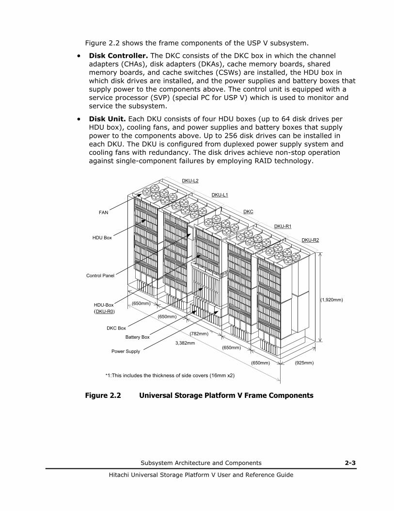
Figure 2.2 shows the frame components of the USP V subsystem.
• Disk Controller. The DKC consists of the DKC box in which the channel adapters (CHAs), disk adapters (DKAs), cache memory boards, shared memory boards, and cache switches (CSWs) are installed, the HDU box in which disk drives are installed, and the power supplies and battery boxes that supply power to the components above. The control unit is equipped with a service processor (SVP) (special PC for USP V) which is used to monitor and service the subsystem.
• Disk Unit. Each DKU consists of four HDU boxes (up to 64 disk drives per HDU box), cooling fans, and power supplies and battery boxes that supply power to the components above. Up to 256 disk drives can be installed in each DKU. The DKU is configured from duplexed power supply system and cooling fans with redundancy. The disk drives achieve non-stop operation against single-component failures by employing RAID technology.
DKC
DKU-R1
(925mm)
(1,920mm)
(650mm)
(650mm)
(650mm)
(650mm)
(782mm) *1
DKU-L2
DKU-L1
DKU-R2
*1:This includes the thickness of side covers (16mm x2)
3,382mm
HDU-Box (DKU-R0)
DKC Box
Battery Box
Power Supply
Control Panel
HDU Box
FAN
Figure 2.2 Universal Storage Platform V Frame Components
2-4 Subsystem Architecture and Components
Hitachi Universal Storage Platform V User and Reference Guide
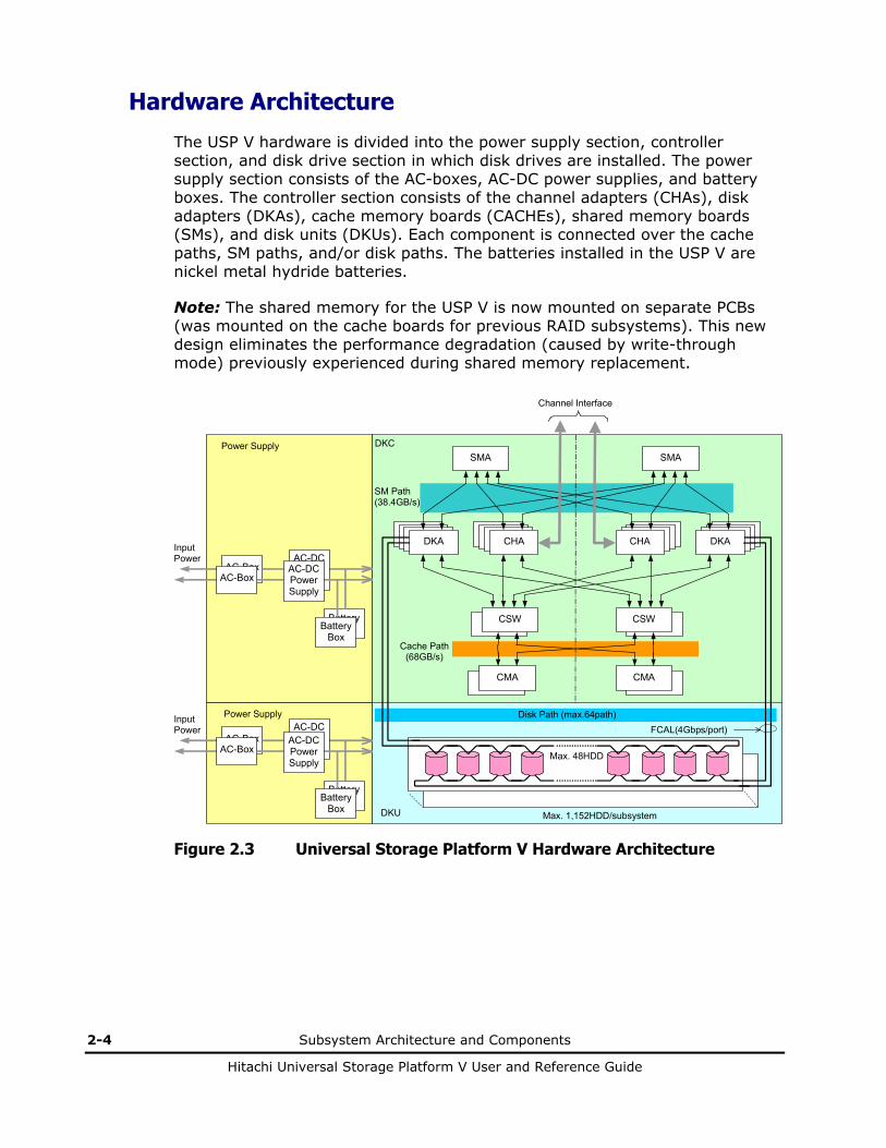
Hardware Architecture
The USP V hardware is divided into the power supply section, controller section, and disk drive section in which disk drives are installed. The power supply section consists of the AC-boxes, AC-DC power supplies, and battery boxes. The controller section consists of the channel adapters (CHAs), disk adapters (DKAs), cache memory boards (CACHEs), shared memory boards (SMs), and disk units (DKUs). Each component is connected over the cache paths, SM paths, and/or disk paths. The batteries installed in the USP V are nickel metal hydride batteries.
Note: The shared memory for the USP V is now mounted on separate PCBs (was mounted on the cache boards for previous RAID subsystems). This new design eliminates the performance degradation (caused by write-through mode) previously experienced during shared memory replacement.
DKA DKA DKA CHA DKA DKA DKA DKA
DKA DKA DKA CHA DKA DKA DKA DKA
CSW CSW CSW CSW
CACHE CMA CACHE CMA
SMA SMA
Channel Interface
FCAL(4Gbps/port)
Cache Path(68GB/s)
SM Path (38.4GB/s)
Max. 48HDD
DKU
BatteryBox Battery
Box
DKC Power Supply
Max. 1,152HDD/subsystem
Disk Path (max.64path)
Input Power
AC-Box AC-Box
AC-DC Power Supply
Input Power
AC-Box AC-Box
AC-DC Power Supply
AC-DC Power Supply
Power Supply
AC-DC Power Supply
BatteryBox Battery
Box
Figure 2.3 Universal Storage Platform V Hardware Architecture
Subsystem Architecture and Components 2-5
Hitachi Universal Storage Platform V User and Reference Guide
Components of the Controller Frame
The USP V controller frame contains the control and operational components of the subsystem and one hard disk unit (HDU) box. The USP V controller is fully redundant and has no active single point of failure. All controller frame components can be repaired or replaced without interrupting access to user data. The key features and components of the controller frame are:
• Storage clusters
• Nonvolatile duplex shared memory
• Nonvolatile duplex cache memory
• Multiple data and control paths
• Redundant power supplies
• Front-end directors
• Channels
• Back-end directors
Storage Clusters
Each controller frame consists of two redundant controller halves called storage clusters. Each storage cluster contains all physical and logical elements (for example, power supplies, channel adapters, disk adapters, cache, control storage) needed to sustain processing within the subsystem. Both storage clusters should be connected to each host using an alternate path scheme, so that if one storage cluster fails, the other storage cluster can continue processing for the entire subsystem.
The front-end and back-end directors are split between clusters to provide full backup. Each storage cluster also contains a separate, duplicate copy of cache and shared memory contents. In addition to the high-level redundancy that this type of storage clustering provides, many of the individual components within each storage cluster contain redundant circuits, paths, and/or processors to allow the storage cluster to remain operational even with multiple component failures. Each storage cluster is powered by its own set of power supplies, which can provide power for the entire storage subsystem in the unlikely event of power supply failure. Because of this redundancy, the USP V can sustain the loss of multiple power supplies and still continue operation.
Note: The redundancy and backup features of the USP V eliminate all active single points of failure, no matter how unlikely, to provide an additional level of reliability and data availability.

2-6 Subsystem Architecture and Components
Hitachi Universal Storage Platform V User and Reference Guide
Nonvolatile Shared Memory
The nonvolatile shared memory contains the cache directory and configuration information for the USP V. The path group arrays (for example, for dynamic path selection) also reside in the shared memory. The shared memory is duplexed, and each side of the duplex resides on the first two SM cards, which are in clusters 1 and 2. The shared memory has separate power supplies and is protected by separate seven-day battery backup.
For the USP V model, shared memory is now mounted on separate boards (previously on the cache boards). This new design eliminates the performance degradation (caused by write-through mode) that was previously experienced during shared memory replacement.
The USP V can be configured with up to 16 GB of shared memory. The size of the shared memory is determined by several factors, including total cache size, number of logical devices (LDEVs), and replication function(s) in use. The replication functions affecting shared memory include TrueCopy, ShadowImage, Universal Replicator, Copy-on-Write Snapshot, FlashCopy V2, Volume Migration, and Copy Manager for TPF. Any required increase beyond the base size is automatically shipped and configured during the upgrade process.
Nonvolatile Cache Memory
The USP V can be configured with a maximum of 256 GB of cache (increments of 4 or 8 GB). All cache memory in the USP V is nonvolatile and is protected by 36-hour battery backup (without de-stage option, cache 132 GB or more) or 48-hour battery backup (without de-stage option, cache 128 GB or less).
The cache in the USP V is divided into two equal areas (called cache A and cache B) on separate cards. Cache A is in cluster 1, and cache B is in cluster 2. The USP V places all read and write data in cache. Write data is normally written to both cache A and B with one channel write operation, so that the data is always duplicated (duplexed) across logic and power boundaries. If one copy of write data is defective or lost, the other copy is immediately de-staged to disk. This “duplex cache” design ensures full data integrity in the unlikely event of a cache memory or power-related failure.
Note: Mainframe hosts can specify special attributes (for example, cache fast write (CFW) command) to write data (typically sort work data) without write duplexing. This data is not duplexed and is usually given a discard command at the end of the sort, so that the data will not be de-staged to the disk drives.
Subsystem Architecture and Components 2-7
Hitachi Universal Storage Platform V User and Reference Guide
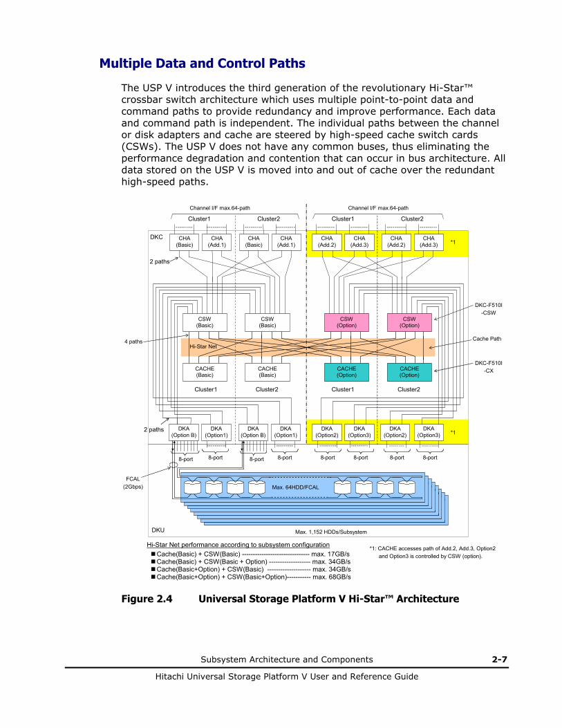
Multiple Data and Control Paths
The USP V introduces the third generation of the revolutionary Hi-Star™ crossbar switch architecture which uses multiple point-to-point data and command paths to provide redundancy and improve performance. Each data and command path is independent. The individual paths between the channel or disk adapters and cache are steered by high-speed cache switch cards (CSWs). The USP V does not have any common buses, thus eliminating the performance degradation and contention that can occur in bus architecture. All data stored on the USP V is moved into and out of cache over the redundant high-speed paths.
Max. 64HDD/FCAL Max. 64HDD/FCAL Max. 64HDD/FCAL Max. 64HDD/FCAL Max. 64HDD/FCAL Max. 64HDD/FCAL Max. 64HDD/FCAL
Channel I/F max.64-path Channel I/F max.64-path
Hi-Star Net
CHA (Basic)
CHA (Add.1)
CHA (Basic)
CHA (Add.1)
CHA (Add.2)
CHA (Add.3)
CHA (Add.2)
CHA (Add.3)
CSW (Basic)
CSW (Basic)
CSW (Option)
CSW (Option)
CACHE (Basic)
CACHE (Basic)
CACHE (Option)
CACHE (Option)
DKA (Option1)
DKA (Option1)
DKA (Option3)
DKA (Option2)
DKA (Option3)
DKA (Option2)
Max. 64HDD/FCAL
DKA (Option B)
8-port 8-port
2 paths
Cluster1 Cluster2 Cluster1 Cluster2
4 paths
8-port
Max. 1,152 HDDs/Subsystem
8-port 8-port 8-port 8-port 8-port
Cluster1 Cluster2 Cluster2 Cluster1
DKA (Option B)
DKC-F510I-CSW
DKC
DKU
FCAL (2Gbps)
DKC-F510I-CX
Hi-Star Net performance according to subsystem configuration Cache(Basic) + CSW(Basic) ------------------------------- max. 17GB/s Cache(Basic) + CSW(Basic + Option) ------------------- max. 34GB/s Cache(Basic+Option) + CSW(Basic) -------------------- max. 34GB/s Cache(Basic+Option) + CSW(Basic+Option)----------- max. 68GB/s
2 paths
*1
*1
*1: CACHE accesses path of Add.2, Add.3, Option2 and Option3 is controlled by CSW (option).
Cache Path
Figure 2.4 Universal Storage Platform V Hi-Star™ Architecture
2-8 Subsystem Architecture and Components
Hitachi Universal Storage Platform V User and Reference Guide
Redundant Power Supplies
Each storage cluster is powered by its own set of redundant power supplies, and each power supply is able to provide power for the entire system, if necessary. Because of this redundancy, the USP V can sustain the loss of multiple power supplies and still continue to operate. To make use of this capability, the USP V should be connected either to dual power sources or to different power panels, so if there is a failure on one of the power sources, the USP V can continue full operations using power from the alternate source.
Channel Adapters and Front-End Directors
The channel adapter boards (CHAs) contain the front-end directors (microprocessors) that process the channel commands from the host(s) and manage host access to cache. In the mainframe environment, the front-end directors perform CKD-to-FBA and FBA-to-CKD conversion for the data in cache. Channel adapter boards are installed in pairs. The channel interfaces on each board can all transfer data at once, independently. Each channel adapter board pair is composed of one type of channel interface (for example, FICON or NAS). Fibre-channel adapters and FICON-channel adapters are available in both shortwave (multimode) and longwave (single-mode) versions. The USP V can be configured with multiple channel adapter pairs to support various interface configurations.
Table 2-1 lists the channel adapter specifications and configurations and the number of channel connections for each configuration.
Note: Hitachi Performance Monitor allows users to collect and view usage statistics for the front-end directors in the USP V.

Subsystem Architecture and Components 2-9
Hitachi Universal Storage Platform V User and Reference Guide
Table 2-1 Channel Adapter Specifications
Parameter Specifications
Number of channel adapter pairs 1, 2, 3, 4, 5, 6, 7, 8, 9, 10, 11, 12, 13, 14
Simultaneous data transfers per CHA pair: FICON ExSA Fibre-channel NAS iSCSI
8 8 8, 16 8 8
Maximum data transfer rate: FICON ExSA Fibre-channel NAS iSCSI
400 MB/sec (4 Gbps) 17 MB/sec 400 MB/sec (4 Gbps) 100 MB/sec (1 Gbps) 100 MB/sec (1 Gbps)
Physical interfaces per CHA pair: FICON ExSA Fibre-channel NAS (Gigabit Ethernet) iSCSI (Gigabit Ethernet)
8 8 16 8 8
Maximum physical interfaces per subsystem: FICON ExSA Fibre-channel NAS iSCSI
8, 16, 24, 32, 40, 48, 56, 64, 62, 80,88, 96,104, 112 8, 16, 24, 32, 40, 48, 56, 64, 62, 80,88, 96,104, 112 16, 32, 48,64, 80,96,112 128, 144,160, 176,192 8, 16, 24, 32 (maximum 4 NAS features) 8, 16, 24, 32, 40, 48
Logical paths per FICON port 65,536 (1024 host paths × 64 CUs) (2105 emulation)
261,120(1024 host paths x 255 CUs) (2107 emulation)
Logical paths per ExSA (ESCON) port 512 (32 host paths × 16 CUs) *
Maximum logical paths per subsystem 1,044,480 FICON (2048 CHLs × 510 CUs) 32,768 ExSA (2048 CHLs × 16 CUs)
Maximum LUs per fibre-channel port 1024
Maximum LDEVs per subsystem 130,560 (256 LDEVs x 510 CUs)
*Note: When the number of devices per CHL image is limited to a maximum of 1024, 16 CU images can be assigned per CHL image. If one CU involves 256 devices, the maximum number of CUs per CHL image is limited to 4.

2-10 Subsystem Architecture and Components
Hitachi Universal Storage Platform V User and Reference Guide
Host Channels
The USP V supports all-mainframe, all-open system, and multiplatform operations and offers the following types of host channel connections:
• FICON. The USP V supports up to 96 FICON ports capable of data transfer speeds of up to 400 MB/sec (4 Gbps). FICON features, available in shortwave (multimode) and longwave (single mode) versions, can have either 8 or 16 FICON host interfaces per pair of channel adapter boards. When configured with shortwave FICON channel adapters, the USP V can be located up to 500 meters (2750 feet) from the host(s). When configured with longwave FICON channel adapters, the USP V can be located up to ten kilometers from the host(s). If you need further FICON-related information, please contact your Hitachi Data Systems representative.
Note: FICON data transmission rates vary according to configuration. Please note:
– S/390 Parallel Enterprise Servers - Generation 5 (G5) and Generation 6 (G6) only support FICON at 1 Gbps.
– z800 and z900 series hosts have the following possible configurations:
FICON channel will operate at 1 Gbps ONLY. FICON EXPRESS channel transmission rates will vary according to microcode release. If microcode is 3G or later, the channel will auto-negotiate to set a 1-Gbps or 2-Gbps transmission rate. If microcode is previous to 3G, the channel will operate at 1 Gbps ONLY.
• Extended Serial Adapter (ExSA) (compatible with ESCON protocol). The USP V supports a maximum of 96 ExSA serial channel interfaces. The ExSA channel interface cards provide data transfer speeds of up to 17 MB/sec and have 16 ports per pair of channel adapter boards. Each ExSA channel can be directly connected to a CHPID or a serial channel director. Shared serial channels can be used for dynamic path switching. The USP V also supports the ExSA Extended Distance Feature (XDF).
• Fibre-Channel. The USP V supports up to 192 fibre-channel ports. The fibre ports are capable of data transfer speeds of 400 MB/sec (4 Gbps). Fibre-channel features can have either 16 or 32 ports per pair of channel adapter boards. The USP V supports shortwave (multimode) and longwave (single-mode) versions of fibre-channel ports on the same adapter card. When configured with shortwave fibre-channel adapters, the USP V can be located up to 500 meters (2750 feet) from the open-system host(s). When configured with longwave fibre-channel adapters, the USP V can be located up to 10 kilometers from the open-system host(s).
• NAS. The USP V supports a maximum of 32 NAS channel interfaces (8 ports per pair of channel adapter boards). The NAS channel interface boards provide data transfer speeds of up to 100 MB/sec. The USP V supports shortwave (multimode) NAS channel adapters and can be located up to 500 meters (2750 feet) from the NAS-attached host(s).
Subsystem Architecture and Components 2-11
Hitachi Universal Storage Platform V User and Reference Guide
• iSCSI. The USP V supports a maximum of 48 iSCSI interfaces. The iSCSI channel interface boards provide data transfer speeds of up to 100 MB/sec. The USP V supports shortwave (multimode) iSCSI channel adapters and can be located up to 500 meters (2750 feet) from the host(s). In an iSCSI environment, the USP V provides user authentication between hosts and ports mutually by using CHAP (challenge handshake authentication protocol).
2-12 Subsystem Architecture and Components
Hitachi Universal Storage Platform V User and Reference Guide
Disk Adapters and Back-End Directors
The disk adapters (DKAs) contain the back-end directors (microprocessors) that control the transfer of data between the disk drives and cache. The disk adapters are installed in pairs for redundancy and performance. Figure 2.5 illustrates a conceptual DKA pair domain. The USP V can be configured with up to four DKA pairs. All functions, paths, and disk drives controlled by one DKA pair are called an “array domain.” An array domain can contain a variety of LVI and/or LU configurations.
The disk drives are connected to the DKA pairs by fibre cables using an arbitrated-loop (FC-AL) topology. Each DKA has eight independent fibre backend paths controlled by eight back-end directors (microprocessors). Each dual-ported fibre-channel disk drive is connected through its two ports to each DKA in a pair over separate physical paths for improved performance as well as redundancy.
Table 2-2 lists the DKA specifications. Each DKA pair can support a maximum of 256 HDDs (in two array frames), including dynamic spare drives (384 HDDs for the first DKA pair). Each DKA pair contains eight buffers (one per fibre path) that support data transfer to and from cache. Each dual-ported disk drive can transfer data over either port. Each of the two paths shared by the disk drive is connected to a separate DKA in the pair to provide alternate path capability. Each DKA pair is capable of 16 simultaneous data transfers to or from the HDDs.

Subsystem Architecture and Components 2-13
Hitachi Universal Storage Platform V User and Reference Guide
62 63 00 01
62 63 00 01
62 63 00 01
62 63 00 01
Fibre Port
DKA Pair
Fibre Loop
Max. 64 HDDs per FCAL
62 63 00 01
62 63 00 01
62 63 00 01
62 63 00 01
DKA (CL1)
0 1 2 3 4 5 6 7
DKA (CL2)
0 1 2 3 4 5 6 7
RAID group (3D+1P / 2D+2D)*1
*1: A RAID group (3D+1P/2D+2D) consists of fibre port number 0, 2, 4, and 6, or 1, 3, 5 and 7.
RAID group (7D+1P / 4D+4D)
Fibre Port Number
Figure 2.5 Conceptual Array Domain for the Universal Storage Platform V
Hitachi Performance Monitor allows users to collect and view usage statistics for the back-end directors in the USP V.
Table 2-2 DKA Specifications
Description Specifications
Number of DKA pairs 1, 2, or 4
Backend paths per DKA pair 16
Backend paths per subsystem 16, 32, or 64
Array group (parity group) type per DKA pair RAID-1, RAID-5, and/or RAID-6 *1
Hard disk drive type 72 GB, 146 GB, 300 GB
Logical device emulation type 3390-x *2 and OPEN-V *3
Backend array interface type Fibre-channel arbitrated loop (FC-AL)
Backend interface transfer rate (burst rate) 200 MB/sec (2 Gbps)
Maximum concurrent backend operations per DKA pair
16
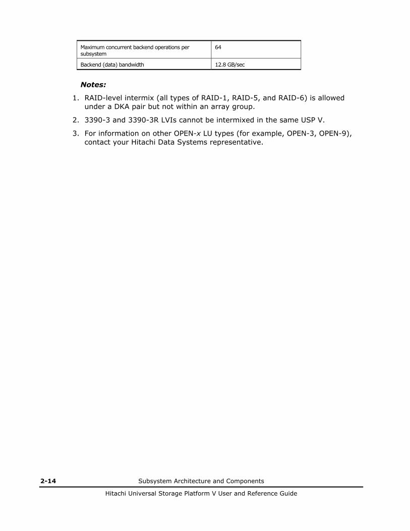
2-14 Subsystem Architecture and Components
Hitachi Universal Storage Platform V User and Reference Guide
Maximum concurrent backend operations per subsystem
64
Backend (data) bandwidth 12.8 GB/sec
Notes:
1. RAID-level intermix (all types of RAID-1, RAID-5, and RAID-6) is allowed under a DKA pair but not within an array group.
2. 3390-3 and 3390-3R LVIs cannot be intermixed in the same USP V.
3. For information on other OPEN-x LU types (for example, OPEN-3, OPEN-9), contact your Hitachi Data Systems representative.

Subsystem Architecture and Components 2-15
Hitachi Universal Storage Platform V User and Reference Guide
Components of the Array Frame
The USP V array frames contain the physical disk drives, including the disk array groups and the dynamic spare disk drives. Each array frame has dual AC power plugs, which should be attached to two different power sources or power panels. The USP V can be configured with up to four array frames to provide a raw storage capacity of up to 332 TB. When configured in four-drive RAID-5 parity groups (3D+1P), ¾ of the raw capacity is available to store user data, and ¼ of the raw capacity is used for parity data.
Hard Disk Drives
The USP V uses disk drives with fixed-block-architecture (FBA) format. The currently available disk drives have capacities of 72 GB (15k rpm), 146 GB (10k rpm), and 300 GB (10k rpm). Table 2-3 provides the disk drive specifications.
Note: Storage capacities for HDDs on the USP V are calculated based on the following values: 1 KB = 1,000 bytes, 1 MB = 1,0002 bytes, 1 GB = 1,0003 bytes, 1 TB = 1,0004 bytes. (Storage capacities for LDEVs on the USP V are based on 1,024 instead of 1,000.)
Each disk drive can be replaced non-disruptively on site. The USP V utilizes diagnostic techniques and background dynamic scrubbing that detect and correct disk errors. Dynamic sparing is invoked automatically if needed. For an array group of any RAID level, any spare disk drive can back up any other disk drive of the same rotation speed and the same or lower capacity anywhere in the subsystem, even if the failed disk and the spare disk are in different array domains (attached to different DKA pairs). The USP V can be configured with a minimum of one and a maximum of 40 spare disk drives (4 slots for spare disks + 36 slots for spare or data disks). The standard configuration provides one spare drive for each type of drive installed in the subsystem. The Hi-Track monitoring and reporting tool detects disk failures and notifies the Hitachi Data Systems Support Center automatically, and a service representative is sent to replace the disk drive.
Note: The spare disk drives are used only as replacements and are not included in the storage capacity ratings of the subsystem.
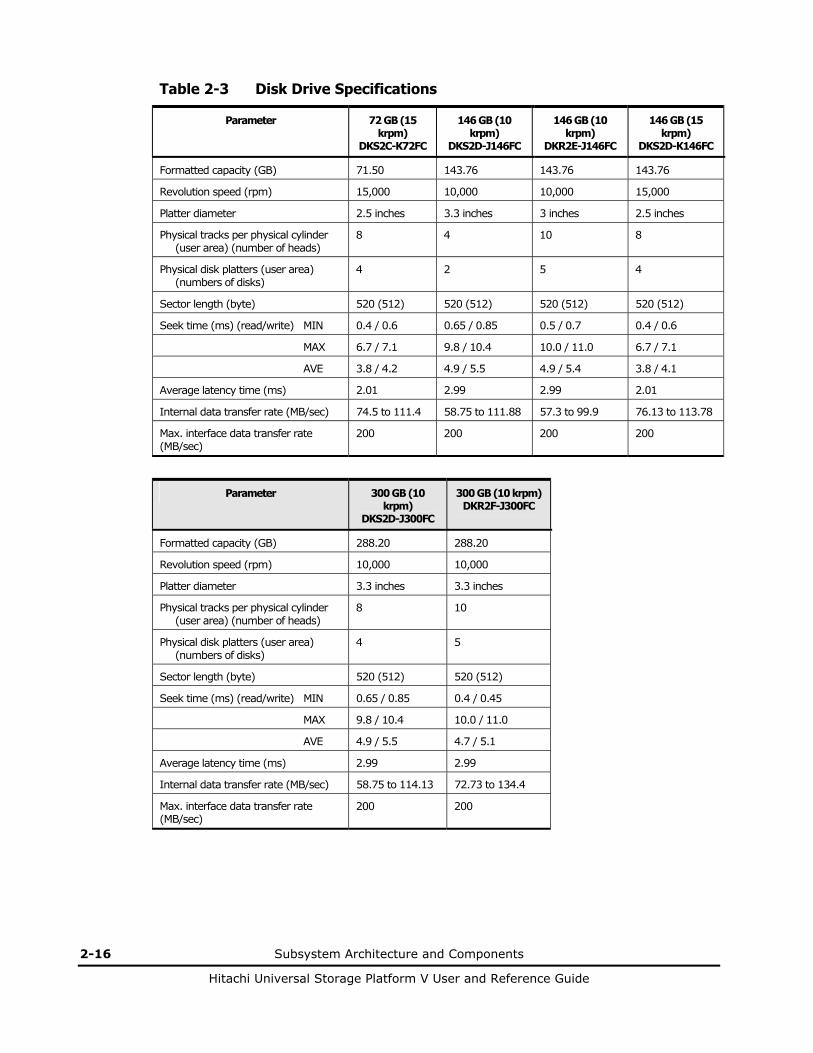
2-16 Subsystem Architecture and Components
Hitachi Universal Storage Platform V User and Reference Guide
Table 2-3 Disk Drive Specifications
Parameter 72 GB (15 krpm)
DKS2C-K72FC
146 GB (10 krpm)
DKS2D-J146FC
146 GB (10 krpm)
DKR2E-J146FC
146 GB (15 krpm)
DKS2D-K146FC
Formatted capacity (GB) 71.50 143.76 143.76 143.76
Revolution speed (rpm) 15,000 10,000 10,000 15,000
Platter diameter 2.5 inches 3.3 inches 3 inches 2.5 inches
Physical tracks per physical cylinder (user area) (number of heads)
8 4 10 8
Physical disk platters (user area) (numbers of disks)
4 2 5 4
Sector length (byte) 520 (512) 520 (512) 520 (512) 520 (512)
Seek time (ms) (read/write) MIN 0.4 / 0.6 0.65 / 0.85 0.5 / 0.7 0.4 / 0.6
MAX 6.7 / 7.1 9.8 / 10.4 10.0 / 11.0 6.7 / 7.1
AVE 3.8 / 4.2 4.9 / 5.5 4.9 / 5.4 3.8 / 4.1
Average latency time (ms) 2.01 2.99 2.99 2.01
Internal data transfer rate (MB/sec) 74.5 to 111.4 58.75 to 111.88 57.3 to 99.9 76.13 to 113.78
Max. interface data transfer rate (MB/sec)
200 200 200 200
Parameter 300 GB (10 krpm)
DKS2D-J300FC
300 GB (10 krpm)DKR2F-J300FC
Formatted capacity (GB) 288.20 288.20
Revolution speed (rpm) 10,000 10,000
Platter diameter 3.3 inches 3.3 inches
Physical tracks per physical cylinder (user area) (number of heads)
8 10
Physical disk platters (user area) (numbers of disks)
4 5
Sector length (byte) 520 (512) 520 (512)
Seek time (ms) (read/write) MIN 0.65 / 0.85 0.4 / 0.45
MAX 9.8 / 10.4 10.0 / 11.0
AVE 4.9 / 5.5 4.7 / 5.1
Average latency time (ms) 2.99 2.99
Internal data transfer rate (MB/sec) 58.75 to 114.13 72.73 to 134.4
Max. interface data transfer rate (MB/sec)
200 200
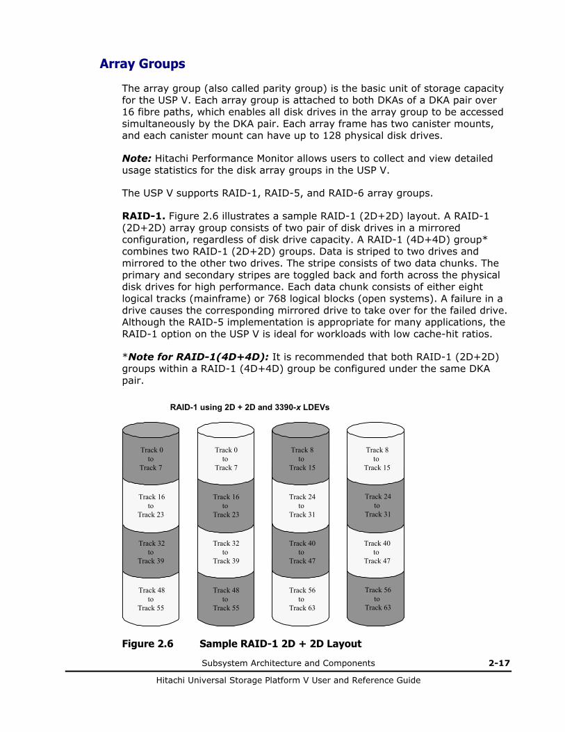
Subsystem Architecture and Components 2-17
Hitachi Universal Storage Platform V User and Reference Guide
Array Groups
The array group (also called parity group) is the basic unit of storage capacity for the USP V. Each array group is attached to both DKAs of a DKA pair over 16 fibre paths, which enables all disk drives in the array group to be accessed simultaneously by the DKA pair. Each array frame has two canister mounts, and each canister mount can have up to 128 physical disk drives.
Note: Hitachi Performance Monitor allows users to collect and view detailed usage statistics for the disk array groups in the USP V.
The USP V supports RAID-1, RAID-5, and RAID-6 array groups.
RAID-1. Figure 2.6 illustrates a sample RAID-1 (2D+2D) layout. A RAID-1 (2D+2D) array group consists of two pair of disk drives in a mirrored configuration, regardless of disk drive capacity. A RAID-1 (4D+4D) group* combines two RAID-1 (2D+2D) groups. Data is striped to two drives and mirrored to the other two drives. The stripe consists of two data chunks. The primary and secondary stripes are toggled back and forth across the physical disk drives for high performance. Each data chunk consists of either eight logical tracks (mainframe) or 768 logical blocks (open systems). A failure in a drive causes the corresponding mirrored drive to take over for the failed drive. Although the RAID-5 implementation is appropriate for many applications, the RAID-1 option on the USP V is ideal for workloads with low cache-hit ratios.
*Note for RAID-1(4D+4D): It is recommended that both RAID-1 (2D+2D) groups within a RAID-1 (4D+4D) group be configured under the same DKA pair.
Track 32 to
Track 39
Track 32to
Track 39
Track 40to
Track 47
Track 56to
Track 63
Track 48 to
Track 55
Track 48to
Track 55
Track 40to
Track 47
Track 56to
Track 63
RAID-1 using 2D + 2D and 3390-x LDEVs
Track 0 to
Track 7
Track 0to
Track 7
Track 8to
Track 15
Track 24to
Track 31
Track 16 to
Track 23
Track 16to
Track 23
Track 8to
Track 15
Track 24to
Track 31
Figure 2.6 Sample RAID-1 2D + 2D Layout

2-18 Subsystem Architecture and Components
Hitachi Universal Storage Platform V User and Reference Guide

Subsystem Architecture and Components 2-19
Hitachi Universal Storage Platform V User and Reference Guide
RAID-5. A RAID-5 array group consists of four (3D+1P) or eight (7D+1P) disk drives. The data is written across the four (or eight) disk drives in a stripe that has three (or seven) data chunks and one parity chunk. Each chunk contains either eight logical tracks (mainframe) or 768 logical blocks (open). The enhanced RAID-5+ implementation in the USP V minimizes the write penalty incurred by standard RAID-5 implementations by keeping write data in cache until an entire stripe can be built and then writing the entire data stripe to the disk drives. The 7D+1P RAID-5 increases usable capacity and improves performance.
Figure 2.7 illustrates RAID-5 data stripes mapped over four physical drives. Data and parity are striped across each of the disk drives in the array group (hence the term “parity group”). The logical devices (LDEVs) are evenly dispersed in the array group, so that the performance of each LDEV within the array group is the same. Figure 2.7 also shows the parity chunks that are the “Exclusive OR” (EOR) of the data chunks. The parity and data chunks rotate after each stripe. The total data in each stripe is either 24 logical tracks (eight tracks per chunk) for mainframe data, or 2304 blocks (768 blocks per chunk) for open-systems data. Each of these array groups can be configured as either 3390-x or OPEN-x logical devices. All LDEVs in the array group must be the same format (3390-x or OPEN-x). For open systems, each LDEV is mapped to a SCSI address, so that it has a TID and logical unit number (LUN).
Track 0 to
Track 7
Parity Tracks
Track 8to
Track 15
ParityTracks
Track 16to
Track 23
next8
tracks
ParityTracks
next8
tracks
RAID-5 using 3D + 1P and 3390-x LDEVs
ParityTracks
Track 24to
Track 31
Track 32 to
Track 39
Track 40to
Track 47
next8
tracks
next8
tracks
next 8
tracks
next8
tracks
Figure 2.7 Sample RAID-5 3D + 1P Layout (Data Plus Parity Stripe)
RAID-6. A RAID-6 array group consists of eight (6D+2P) disk drives. The data is written across the eight disk drives in a stripe that has six data chunks and two parity chunks. Each chunk contains either eight logical tracks (mainframe) or 768 logical blocks (open).
In the case of RAID-6, data can be assured when up to two drives in an array group fail. Therefore, RAID-6 is the most reliable of the RAID levels.

2-20 Subsystem Architecture and Components
Hitachi Universal Storage Platform V User and Reference Guide
Sequential Data Striping
The USP V’s enhanced RAID-5+ implementation attempts to keep write data in cache until parity can be generated without referencing old parity or data. This capability to write entire data stripes, which is usually achieved only in sequential processing environments, minimizes the write penalty incurred by standard RAID-5 implementations. The device data and parity tracks are mapped to specific physical disk drive locations within each array group. Therefore, each track of an LDEV occupies the same relative physical location within each array group in the subsystem.
LDEV Striping Across Array Groups
In addition to the conventional concatenation of RAID-1 array groups (4D+4D), the USP V supports LDEV striping across multiple RAID-5 array groups for improved LU performance in open-system environments. The advantages of LDEV striping are:
• Improved performance, especially of an individual LU, due to an increase in the number of HDDs that constitute an array group.
• Better workload distribution: in the case where the workload of one array group is higher than another array group, you can distribute the workload by combining the array groups, thereby reducing the total workload concentrated on each specific array group.
Note: The LDEV striping feature should only be used to resolve a performance problem (disk drive bottleneck) due to heavy I/O activity to an individual LDEV.
The supported LDEV striping configurations are:
• LDEV striping across two RAID-5 (7D+1P) array groups (see Figure 2.8). The maximum number of LDEVs in this configuration is 1000.
• LDEV striping across four RAID-5 (7D+1P) array groups (see Figure 2.9). The maximum number of LDEVs in this configuration is 2000.

Subsystem Architecture and Components 2-21
Hitachi Universal Storage Platform V User and Reference Guide
Array group 1 (7D+1P) Array group 2 (7D+1P)
LDEV#A
A-1 A-2 A-3 A-4
B-1 B-2 B-3
A-2
A-4
B-1
B-3
B-4
A-1
A-3 B-4
B-2
Array group 1 (7D+1P) Array group 2 (7D+1P)
LDEV#B
LDEV Striping
Figure 2.8 LDEV Striping Across 2 RAID-5 (7D+1P) Array Groups

2-22 Subsystem Architecture and Components
Hitachi Universal Storage Platform V User and Reference Guide
ECC group 1 (7D+1P) ECC group 2 (7D+1P)
LDEV#A
A-1 A-2 A-3 A-4
B-1 B-2 B-3 B-4
LDEV#B
ECC group 3 (7D+1P) ECC group 4 (7D+1P)
LDEV#C
C-1 C-2 C-3 C-4
D-1 D-2 D-3 D-4
LDEV#D
ECC group 1 (7D+1P) ECC group 2 (7D+1P)
A-1 D-2 C-3 B-4
B-1 A-2 D-3 C-4
ECC group 3 (7D+1P) ECC group 4 (7D+1P)
C-1 B-2 A-3 D-4
D-1 C-2 B-3 A-4
LDEV Striping
Figure 2.9 LDEV Striping Across 4 RAID-5 (7D+1P) Array Groups
All disk drives and device emulation types are supported for LDEV striping. LDEV striping can be used in combination with all USP V data management functions, with the following restriction in Volume Migration:
• In Volume Migration operations (optimizing LDEV allocation), you cannot migrate an array group within a combined/striped group to another group. Volume Migration migrates all LDEVs in an array group to another array group.

Subsystem Architecture and Components 2-23
Hitachi Universal Storage Platform V User and Reference Guide
Array Group 1 7D+1P
Array Group 2 7D+1P
7D+1P 2 concatenations
Array Group 2 7D+1P
You cannot migrate only one of the groups.
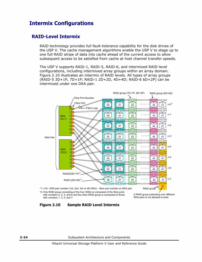
2-24 Subsystem Architecture and Components
Hitachi Universal Storage Platform V User and Reference Guide
Intermix Configurations
RAID-Level Intermix
RAID technology provides full fault-tolerance capability for the disk drives of the USP V. The cache management algorithms enable the USP V to stage up to one full RAID stripe of data into cache ahead of the current access to allow subsequent access to be satisfied from cache at host channel transfer speeds.
The USP V supports RAID-1, RAID-5, RAID-6, and intermixed RAID-level configurations, including intermixed array groups within an array domain. Figure 2.10 illustrates an intermix of RAID levels. All types of array groups (RAID-5 3D+1P, 7D+1P; RAID-1 2D+2D, 4D+4D; RAID-6 6D+2P) can be intermixed under one DKA pair.
46 47
46 47
46 47
46 47
46 47
46 47
46 47
46 47
00
00
00
00
Fibre Port
DKA Pair
Fibre Loop
00
00
00
00
01
01
01
01
01
01
01
01
DKA (CL1)
0 1 2 3 4 5 6 7
DKA (CL2)
0 1 2 3 4 5 6 7
RAID5(3D+1P)*2
*2: One RAID group consisting of the four HDDs is composed of the fibre ports with numbers 0, 2, 4, and 6 and the other RAID group is composed of those with numbers 1, 3, 5, and 7.
RAID group (4D+4D)
02
02
02
02
02
02
02
02
RAID1(2D+2D)*2
n-0*1
n-1
n-2
n-3
n-4
n-5
n-6
n-7
*1: n-N-- DKA pair number (1st, 2nd, 3rd or 4th DKA) – fibre port number on DKA pair.
RAID group (7D+1P, 6D+2P)
A RAID group extending over different DKA pairs is not allowed to exist.
RAID group
Fibre Port Number
Figure 2.10 Sample RAID Level Intermix

Subsystem Architecture and Components 2-25
Hitachi Universal Storage Platform V User and Reference Guide
Hard Disk Drive Intermix
All hard disk drives (HDDs) in one array group (parity group) must be of the same capacity and type. Different HDD types can be attached to the same DKA pair.
Note: For the latest information on available HDD types and intermix requirements, please contact your Hitachi Data Systems account team.
Device Emulation Intermix
Figure 2.11 illustrates an intermix of device emulation types. The USP V supports an intermix of all device emulations on the same DKA pair, with the restriction that the devices in each array group have the same type of track geometry or format.
The Virtual LVI/LUN (also called CVS) function enables different logical volume types to coexist. When Virtual LVI/LUN is not being used, an array group can be configured with only one device type (for example, 3390-3 or 3390-9, not 3390-3 and 3390-9). When Virtual LVI/LUN is being used, you can intermix 3390 device types, and you can intermix OPEN-x device types, but you cannot intermix 3390 and OPEN device types.
Note: For the latest information on supported LU types and intermix requirements, please contact your Hitachi Data Systems account team.
4thDKAPair
2ndDKAPair
3rdDKAPair
1stDKAPair
OPEN-3 3390-9 OPEN-V
Disk Array Unit Disk Array Unit
3390-9 3390-3
OPEN-V
Disk Array UnitDisk Array UnitUniversal Storage Platform DKC
Figure 2.11 Sample Device Emulation Intermix

2-26 Subsystem Architecture and Components
Hitachi Universal Storage Platform V User and Reference Guide
Service Processor (SVP)
The USP V includes a built-in custom PC called the service processor (SVP). The SVP is integrated into the controller frame and can only be used by authorized Hitachi Data Systems personnel. The SVP enables the Hitachi Data Systems representative to configure, maintain, and upgrade the USP V. The SVP also collects performance data for all key components of the USP V to enable diagnostic testing and analysis. In addition, the USP V Storage Navigator functionality is provided by the SVP. Connecting the SVP with a service center enables remote maintenance of the subsystem.
Note: The USP V can be equipped with an optional duplicate SVP for additional reliability.
Important: The SVP does not have access to any user data stored on the USP V.

Subsystem Architecture and Components 2-27
Hitachi Universal Storage Platform V User and Reference Guide
Storage Navigator
The Storage Navigator for USP V is provided as a Java® applet program which can be executed on any machine that supports a Java Virtual Machine (JVM). A PC hosting the Storage Navigator (called a “remote console”) is attached to the USP V system(s) over a TCP/IP local-area network (LAN). When a remote console accesses and logs into the desired SVP the Storage Navigator applet is downloaded from the SVP to the remote console, runs in the Web browser, and communicates with the attached USP V subsystem(s) over a TCP/IP network. Figure 2.12 shows an example of remote console and SVP configuration.
Two LANs can be attached to the USP V: the RAID-internal LAN (private LAN), which is used to connect the SVP(s) of multiple systems, and the user’s intranet (public LAN), which allows you to access the Storage Navigator functions from individual remote console PCs. The remote console communicates directly with the service processor (SVP) of each attached subsystem to obtain subsystem configuration and status information and send user-requested commands to the subsystem. The Storage Navigator Java applet program is downloaded to the remote console (Web client) from the SVP (Web server) each time the remote console connects to the SVP. The Storage Navigator Java applet program runs in Web browsers (for example, Internet Explorer or Mozilla) which run under the Windows®, Solaris, and Linux® operating systems to provide a user-friendly interface for the USP V remote console functions.
Note: For further information on the USP V Storage Navigator software and remote console hardware, please see the Hitachi USP V (USP V) Storage Navigator User’s Guide (MK-96RD621).
Web Server (JVM™)
Private LAN
Web Client Java™ Applet
Download
Data communication
Web Client
Java™ Applet program is running. Configuration
information Information acquisition
Web Browser
Web Client (JVM™)
Storage Navigator Private LAN
Universal Storage PlatformSVP
Public LAN
RMI™Server
HTTPDserver
Figure 2.12 Example of Storage Navigator and SVP Configuration

2-28 Subsystem Architecture and Components
Hitachi Universal Storage Platform V User and Reference Guide
3
Functional and Operational Characteristics 3-1
Hitachi Universal Storage Platform V User and Reference Guide
Functional and Operational Characteristics
This chapter discusses the functional and operational capabilities of the USP V.
New Features and Capabilities of the Universal Storage Platform V
I/O Operations
Cache Management
Control Unit (CU) Images, LVIs, and LUs
System Option Modes
Open Systems Features and Functions
Open-Systems Configuration
Data Management Functions
3-2 Functional and Operational Characteristics
Hitachi Universal Storage Platform V User and Reference Guide
New Features and Capabilities of the Universal Storage Platform V
The Hitachi USP V (USP V) offers the following new and improved features and capabilities which distinguish this model from the Lightning 9900V® subsystem:
• New – Up to 32 PBs of external storage capacity (no external storage for 9900V)
• Up to 332 TB (raw) internal storage capacity (147 TB for 9900V)
• Sixty-four (64) control unit (CU) images (32 for 9900V)
• Up to 16,384 device addresses (8192 for 9900V)
• Up to 1,152 HDDs (1,024 HDDs in the 9900V)
• Up to 1024 LUNs per fibre-channel port (512 for 9900V)
• Internal bandwidth increased by over 4 times relative to 9900V
• State-of-the-art hard disk drives of 72-GB, 146-GB, and 300-GB capacities
• LDEV striping across multiple RAID-5 array groups
Functional and Operational Characteristics 3-3
Hitachi Universal Storage Platform V User and Reference Guide
I/O Operations
The USP V I/O operations are classified into three types based on cache usage:
• Read hit: For a read I/O, when the requested data is already in cache, the operation is classified as a read hit. The front-end director searches the cache directory, determines that the data is in cache, and immediately transfers the data to the host at the channel transfer rate.
• Read miss: For a read I/O, when the requested data is not currently in cache, the operation is classified as a read miss. The front-end director searches the cache directory, determines that the data is not in cache, disconnects from the host, creates space in cache, updates the cache directory, and requests the data from the appropriate DKA pair. The DKA pair stages the appropriate amount of data into cache, depending on the type of read I/O (for example, sequential).
• Fast write: All write I/Os to the USP V are fast writes, because all write data is written to cache before being de-staged to disk. The data is stored in two cache locations on separate power boundaries in the nonvolatile duplex cache. As soon as the write I/O has been written to cache, the USP V notifies the host that the I/O operation is complete, and then de-stages the data to disk.

3-4 Functional and Operational Characteristics
Hitachi Universal Storage Platform V User and Reference Guide
Cache Management
The USP V places all read and write data in cache, and 100% of cache memory is available for read operations. The amount of fast-write data in cache is dynamically managed by the cache control algorithms to provide the optimum amount of read and write cache, depending on the workload read and write I/O characteristics.
The following sections explain how the cache is managed.
Algorithms for Cache Control
The algorithms for internal cache control used by the USP V include the following:
• Hitachi Data Systems Intelligent Learning Algorithm. The Hitachi Data Systems Intelligent Learning Algorithm identifies random and sequential data access patterns and selects the amount of data to be “staged” (read from disk into cache). The amount of data staged can be a record, partial track, full track, or even multiple tracks, depending on the data access patterns.
• Least-recently-used (LRU) algorithm (modified). When a read hit or write I/O occurs in a non-sequential operation, the least-recently-used (LRU) algorithm marks the cache segment as most recently used and promotes it to the top of the appropriate LRU list. In a sequential write operation, the data is de-staged by priority, so the cache segment marked as least-recently used is immediately available for reallocation, since this data is not normally accessed again soon.
• Sequential prefetch algorithm. The sequential pre-fetch algorithm is used for sequential-access commands or access patterns identified as sequential by the Intelligent Learning Algorithm. The sequential pre-fetch algorithm directs the back-end directors to pre-fetch up to one full RAID stripe (24 tracks) to cache ahead of the current access. This allows subsequent access to the sequential data to be satisfied from cache at host channel transfer speeds.
Note: The USP V supports mainframe extended count key data (ECKD) commands for specifying cache functions.
Write Pending Rate
The write pending rate is the percent of total cache used for write pending data. The amount of fast-write data stored in cache is dynamically managed by the cache control algorithms to provide the optimum amount of read and write cache based on workload I/O characteristics. Hitachi Performance Monitor allows users to collect and view the write-pending-rate data and other cache statistics for the USP V.
Functional and Operational Characteristics 3-5
Hitachi Universal Storage Platform V User and Reference Guide
Note: If the write pending limit is reached, the USP V sends DASD fast-write delay or retry indications to the host until the appropriate amount of data can be de-staged from cache to the disks to make more cache slots available.

3-6 Functional and Operational Characteristics
Hitachi Universal Storage Platform V User and Reference Guide
Control Unit (CU) Images, LVIs, and LUs
CU Images
The USP V supports the following control unit emulation types: 3990-6, 3990-6E, and 2105 (2105-F20 required for FICON connection). The USP V is configured with one control unit (CU) image for each 256 devices (one storage subsystem ID (SSID) for each 64 or 256 LDEVs) to provide a maximum of 255 CU images per subsystem. The mainframe data management features of the USP V may have restrictions on CU image compatibility. For further information on CU image support, please contact your Hitachi Data Systems account team.
Logical Volume Image (LVIs)
The USP V supports the following mainframe LVI types: 3390-3, -3R, -9, -L, and -M. The LVI configuration of the subsystem depends on the RAID implementation and physical disk drive capacities. The USP V LDEVs are accessed using a combination of CU number (00-FE) and device number (00-FF). All control unit images can support an installed LVI range of 00 to FF.
Note on 64K LDEV addressing: LDEVs in all global logical partitions (GLPRs) are supported with cache logical partition (CLPR), storage logical partition (SLPR), Hitachi Performance Monitor feature, Virtual LVI (also called CVS), Hitachi Cache Residency Manager, Hitachi Compatible PAV for IBM z/OS, and Hitachi Volume Shredder software.
Logical Unit (LU) Type
The USP V is configured with OPEN-V LU types. For information on other LU types (for example, OPEN-3, OPEN-9), please contact your Hitachi Data Systems representative. The OPEN-V LU can vary in size from 48.1 MB to 64.422 GB.
Note: Storage capacities for LUs on the USP V are calculated based on the following values: 1 KB = 1,024 bytes, 1 MB = 1,0242 bytes, 1 GB = 1,0243 bytes, 1 TB = 1,0244 bytes. (Storage capacities for HDDs on the USP V are based on 1,000 instead of 1,024.)
For maximum flexibility in LU configuration, the USP V supports the Virtual LVI/LUN (VLL) and LUN Expansion (LUSE) features. Virtual LVI/LUN allows users to configure multiple devices (LVIs or LUs) under a single volume, and LUN Expansion (LUSE) enables users to concatenate multiple LUs into single volumes.
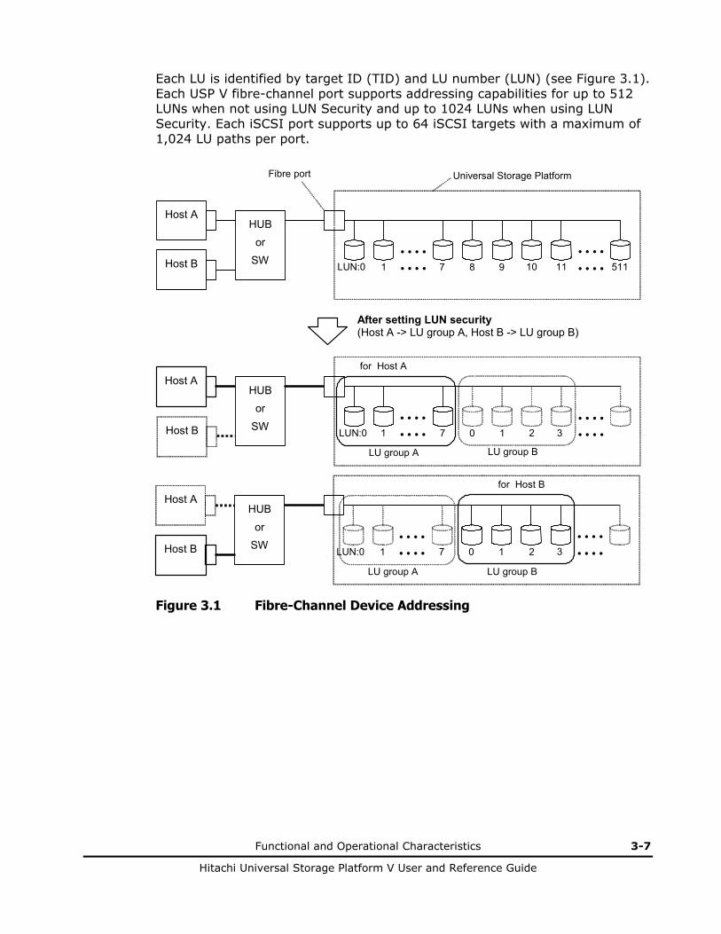
Functional and Operational Characteristics 3-7
Hitachi Universal Storage Platform V User and Reference Guide
Each LU is identified by target ID (TID) and LU number (LUN) (see Figure 3.1). Each USP V fibre-channel port supports addressing capabilities for up to 512 LUNs when not using LUN Security and up to 1024 LUNs when using LUN Security. Each iSCSI port supports up to 64 iSCSI targets with a maximum of 1,024 LU paths per port.
Host A
LUN:0
Fibre port Universal Storage Platform
• • • • Host B
HUB or
SW
Host A
Host B
HUB or
SW LUN:0
LU group A LU group B
Host A
Host B
HUB or
SW
LU group A LU group B
After setting LUN security (Host A -> LU group A, Host B -> LU group B)
1 7 8 9 10 11 511 • • • •
• • • •
• • • • • • • •
• • • •
1 7 0 1 2 3 • • • • • • • •
LUN:0 1 7 0 1 2 3 • • • • • • • • • • • • • • • •
for Host A
for Host B
Figure 3.1 Fibre-Channel Device Addressing

3-8 Functional and Operational Characteristics
Hitachi Universal Storage Platform V User and Reference Guide
System Option Modes
To provide greater flexibility and enable the USP V to be tailored to unique customer operating requirements, additional operational parameters, or system option modes, are available for the USP V. At installation, the USP V modes are set to their default values, so make sure to discuss these settings with your Hitachi Data Systems team. The USP V system option modes can only be changed by the Hitachi Data Systems representative.
Table 3-1 lists the USP V system option mode information for microcode 50-07-51-00/00. Mode information may change in future microcode releases. Please contact your Hitachi Data Systems representative for the latest information on the USP V system option modes.
Note on host group modes: The host group modes and host group mode options (set using LUN Manager) are not described in this document. For details on the host group modes and host group mode options, see the LUN Manager User’s Guide (MK-94RD203).
Table 3-1 System Option Modes for the Universal Storage Platform V
Mode Function Default MCU/RCU Remarks
20 R-VOL read only function. OFF RCU For TrueCopy for z/OS
21 This option must be set on both the MCU and RCU for TrueCopy and TrueCopy for z/OS (not required for XRC). This option must be ON for MCUs and RCUs which connect to CNT® channel extenders.
ON: Mandatory setting when channel extenders are connected.
OFF: Channel extenders should never be connected with this setting.
OFF MCU/RCU For remote copy with CNT Channel Extender
36 TrueCopy for z/OS Synchronous – Selects function of CRIT=Y(ALL) or CRIT=Y(PATHS).
ON: CRIT=Y(ALL) equivalent to Fence Level = Data.
Write I/Os from the host will be rejected when PPRC pairs are suspended.
OFF: CRIT=Y(PATHS) equivalent to Fence Level = Status.
If the pair status of M-VOL and R-VOL is inconsistent, the operation is the same as the above. Otherwise, write I/Os from the host will be accepted when PPRC pairs are suspended.
OFF MCU For TrueCopy for z/OS
45 Sleep Wait suppressing option (see modes 61, 85, 86, 97).
ON: Sidefile threshold does not activate Sleep Wait timer at the sleep wait threshold.
OFF: Sidefile threshold activates Sleep Wait timer at the sleep wait threshold
When Mode 45 is ON and Mode 61 is ON, WRITE I/Os for LDEVs are blocked by the threshold specified by SDM.
OFF For XRC

Functional and Operational Characteristics 3-9
Hitachi Universal Storage Platform V User and Reference Guide
49 TC for z/OS – Changes reporting of SSIDs in response to CQUERY command (which is limited to four SSIDs). When 64 LDEVs per SSID are defined, mode 49 must be ON for TCz, GDPS, and P/DAS operations. When 256 LDEVs per SSID are defined, mode 49 must be OFF.
ON: Report first SSID for all (256) devices in the logical CU.
OFF: Report SSID specified for each 64 or 256 devices.
OFF MCU For TrueCopy for z/OS
61 Enables the DONOTBLOCK option of the XADDPAIR command . Must be OFF if the OS does not support the DONOTBLOCK option.
ON: DONOTBLOCK option activated.
OFF: DONOTBLOCK option ignored.
OFF For XRC
64 TCz CGROUP – Defines scope of CGROUP command within the Universal Storage Platform V. Must be OFF for GDPS.
ON: All TCz volumes in this USP V subsystem.
OFF: TCz volumes behind the specified LCU pair (main and remote LCUs).
OFF MCU For TrueCopy for z/OS
80 Suppression of ShadowImage (BC) Quick Restore function
ON: Subsystem does not perform SI Quick Restore operation.
OFF: Subsystem performs SI Quick Restore operation.
ON For ShadowImage (BC)
85 86
Variable sidefile threshold
Mode 85 Mode 86
ON OFF Thresholds for Sleep wait/SCP/Puncture = 30/40/50%
OFF OFF Thresholds for Sleep wait/SCP/Puncture = 40/50/60%
OFF ON Thresholds for Sleep wait/SCP/Puncture = 50/60/70%
ON ON Thresholds for Sleep wait/SCP/Puncture = 60/70/80%
OFF For XRC
87 ShadowImage Quick Resync by RAID Manager
ON: Subsystem performs ShadowImage Quick Resync operation for Resync command from CCI.
OFF: Subsystem does not perform ShadowImage Quick Resync operation for Resync command from CCI.
OFF For ShadowImage
93 TCz Asynchronous graduated delay process for sidefile control
ON: soft delay type
OFF: strong delay type
OFF MCU
97 Variable Sleep Wait timer duration (see modes 45, 85, 86).
ON: Sleep Wait timer duration = 10 ms.
OFF: Sleep Wait timer duration = 100 ms.
OFF For XRC
98 Selects SCP or session cancel (see modes 45, 85, 86).
ON: Forced session cancel.
OFF: SCP
OFF For XRC
3-10 Functional and Operational Characteristics
Hitachi Universal Storage Platform V User and Reference Guide
104 TCz CGROUP – Selects subsystem default for CGROUP FREEZE option. Applies to 3990 emulation only.
ON: FREEZE enabled.
OFF: FREEZE disabled.
OFF MCU For TrueCopy for z/OS
114 TCz – Allows dynamic port mode setting (RCP/LCP for serial, Initiator/RCU target for fiber-channel) through PPRC CESTPATH and CDELPATH commands.
ON: Set defined port to RCP/LCP mode (serial) or Initiator/RCU target mode (fiber-channel) as needed.
OFF: Port must be reconfigured using Remote Console PC (or SVP).
OFF MCU/RCU For TrueCopy for z/OS
118 XRC, CC, TCz Async – SIM notification when: XRC+CC sidefile reaches sleep wait threshold (see modes 45, 85, 86, 97). TCz Async sidefile reaches high-water mark (HWM = sidefile threshold - 20%) (see mode 93).
ON: Generate SIM.
OFF: No SIM generated.
OFF For XRC, CC, and TCz Asynchronous
122 Suppression of ShadowImage (BC) Quick Split and Resync function.
ON For ShadowImage
186 Host Mode Option 2 is used instead of System Option Mode186
OFF OPEN
190 TCz – Allows you to update the VOLSER and VTOC of the R-VOL while the pair is suspended if both mode 20 and 190 are ON.
MODE 190 ON and MODE 20 ON: R-VOL Read allowed & Write allowed to VTOC area (CYL#0,HD#0-14).
MODE 190 ON and MODE 20 OFF: No R-VOL Read/Write.
MODE 190 OFF and MODE 20 ON: R-VOL Read allowed & Write allowed to VOLSER ((CYL#0,HD#0,REC#3).
MODE 190 OFF and MODE 20 OFF: No R-VOL Read/Write.
OFF RCU For TrueCopy for z/OS
213 AIX+HACMP
Host Mode Option 5 is used instead of System Option Mode 213
OFF OPEN
225 (1) For VMware (Host Mode '0A')
(2) Mode option for XP product. (NetWare Multi-pathing )
ON: NetWare Multipath is usable.
OFF: NetWare Multipath is unusable.
OFF This function is provided by default of Host Mode '0A'.
228 OpenVMS® Alternate path
OFF: OpenVMS alternate path is not available
ON: OpenVMS alternate path is available
OFF
246 Support of RAID RANK information for Read Subsystem Data (in case of 2105 DKC emulation type)
OFF Mainframe
249 Host Mode Option 7 is used instead of System Option Mode 249
Report Unit Attention when LUN is added (Linux/Solaris)
ON : Unit Attention is reported
OFF (Default) : Unit Attention is not reported
OFF OPEN

Functional and Operational Characteristics 3-11
Hitachi Universal Storage Platform V User and Reference Guide
258 To disable the MCU Sidefile buffer function for TrueCopy Async OPEN.
Before downgrading the micro-program from an MCU Sidefile buffer supported version (50-06-11-00/00 or higher) to an unsupported version (lower than 50-06-11-00/00), it is required to set mode 258 to ON.
Mode 258 = ON: The MCU Sidefile buffer function for TrueCopy Async OPEN is unavailable.
Mode 258 = OFF (default): The MCU Sidefile buffer function for TrueCopy Async OPEN is available.
OFF MCU/RCU For TrueCopy Async
269 High Speed Format for CVS (Available for all DKU emulation types)
(1) High Speed Format support: In case of redefining all LDEVs included in ECC group using Volume Initialize or Make Volume on CVS setting panel, LDEV format, as the last process, will be performed in high speed.
(2) Make Volume feature enhancement: In addition, with supporting the feature, the Make Volume feature (recreating new CVs after deleting all volumes in a VDEV), which was supported for OPEN-V only, is available for all device types.
OFF
272 Host Mode Option 14 is used instead of System Option Mode 272
TrueCopy TruCluster in TrueCopy environment
To activate this feature, set System Option Mode 247(for Tru64) and Mode 272 (TrueCopy TruCluster) to ON.
OFF MCU/RCU For TrueCopy
278 Adding/Reducing LUNs for OpenVMS/Tru64 Online OFF
280 Host Mode Option 13 is used instead of System Option Mode 282 & 283
HP-UX Ghost LUN
OFF OPEN
292 Issuing OLS when Switching Port
If a mainframe host (FICON) is connected with the CNT-made FC switch (FC9000 etc.) and is using along with TrueCopy for z/OS with Open Fibre connection, the occurrence of Link Incident Report for the mainframe host from the FC switch will be deterred when switching the CHT port attribute (including automatic switching when executing CESTPATH and CDELPATH in case of Mode 114 = ON).
ON: When switching the port attribute, issue the OLS (100ms) first, and then reset the Chip.
OFF: When switching the port attribute, reset the Chip without issuing the OLS.
OFF MCU/RCU For mainframe remote copy with CNT FC switch
308 SIM RC=2180 option (TC MF)
SIM RC=2180 (RIO path failure between MCU and RCU) was not reported to host. DKC reports SSB with F/M=F5 instead of reporting SIM RC=2180 in the case. Micro-program has been modified to report SIM RC=2180 with newly assigned system option mode as individual function for specific customer.
ON: SIM RC 2180 is reported (compatible with older Hitachi specification).
OFF: Reporting is compatible with IBM - Sense Status report of F5.
OFF MCU For TrueCopy for z/OS

3-12 Functional and Operational Characteristics
Hitachi Universal Storage Platform V User and Reference Guide
313 OPEN-V Geometry: When Host Mode Option 16=ON or System Option Mode 313=ON, the same geometry shared by USP V and 9900V can be responded to the host. When changing System Option Mode 313 or Host Mode Option 16, the connected server should be powered off.
OFF
316 Auto Negotiation in fixed speed. In case the signal synchronizing has been unmatched for 2.6 seconds during Auto Negotiation, the fixed speed can be set as follows:
Mode 316 ON: 1Gbps
Mode 316 OFF: 2Gbps
The mode should be set when a fixed speed of Auto Negotiation is needed though the transfer speed may slow down.
The mode is available for 16HS, 32HS, 16FS, and 32FS.
OFF
334 To reset the iSCSI protocol chip when a port error is detected.
For the iSCSI channel adapter option, when the firmware of the iSCSI protocol chip detects a port error, the chip is reset to expect a host retry without blocking the port if the number of errors does not exceed the threshold (20 per 24 hours).
Mode 334 ON: The chip is reset if the number of errors does not exceed the threshold (20 per 24 hours) when the iSCSI firmware detects a port error. The port is blocked if the number of errors exceeds the threshold.
Mode 334 OFF (default): The port is blocked when the iSCSI firmware detects an error.
OFF
448 ON: (Enabled) If the SVP detects a blocked path, the SVP assumes that an error occurred, and then immediately splits (suspends) the mirror.
OFF: (Disabled) If the SVP detects a blocked path and the path does not recover within the specified period of time, the SVP assumes that an error occurred, and then splits (suspends) the mirror.
Note: The mode 448 setting takes effect only when mode 449 is set to OFF.
OFF Universal Replicator
449 Detecting and monitoring path blockade between MCU and RCU of Universal Replicator/Universal Replicator for z/OS
<Functionality>
MODE 449 ON: Detecting and monitoring of path blockade will NOT be performed. ON is the default for DKCMAIN Ver. 50-04-40 and later.
MODE 449 OFF (default*): Detecting and monitoring of the path blockade will be performed. OFF is the default for DKCMAIN Ver. 50-04-3x and earlier.
Note: The mode status will not be changed by the microcode exchange.
OFF Mode 449 = ON is the default for DKCMAIN Ver. 50-04-40-00/00 and later.
454 When making a de-stage schedule for CLPRs, using the average workload of all the CLPRs or the highest workload of those of the CLPRs can be optional.
Mode 454 = ON: The average workload of all the CLPRs is used to make the de-stage schedule.
Mode 454 = OFF (default): The highest workload of those of the CLPRs is used to make the de-stage schedule.
Note: The priority of the de-stage processing for a specific CLPR in the overloaded status decreases and the overloaded status is not released so that TOV (MIH) may occur.
OFF Virtual Partition Manager
Functional and Operational Characteristics 3-13
Hitachi Universal Storage Platform V User and Reference Guide
457 50-03-93-00/00 and later: High Speed LDEV Format for External Volumes
The high speed LDEV format for external volumes is available by setting system option mode 457 to ON. When system option mode 457 is ON, when selecting the external volume group and performing the LDEV format, any write processing on the external LUs will be skipped. However, if the emulation type of the external LDEV is mainframe, the write processing for mainframe control information only will be performed after the write skip.
50-04-28-00/00 and later: Support for Mainframe Control Block Write GUI
When system option mode 457 is ON, the high speed LDEV format for external volumes was supported at V03. In V04, Control Block Write of the external LDEVs in mainframe emulation is supported by Storage Navigator.
- In case the LDEV is not written with data “0” before performing the function, the LDEV format may fail.
- After the format processing, be sure to set system option mode 457 to OFF.
OFF
459 In case the secondary volume of an SI/SIz pair is an external volume, the transaction to change the status from SP-PEND to SPLIT is as follows.
(1) System Option Mode 459 = ON when creating an SI/SIz pair
The copy data is created in cache memory. When the write processing on the external storage completes and the data is fixed, the pair status will change to SPLIT.
(2) System Option Mode 459 = OFF when creating an SI/SIz pair
Once the copy data has been created in cache memory, the pair status will change to SPLIT. The external storage data is not fixed (current spec).
OFF For ShadowImage and ShadowImage for z/OS
460 When turning off PS, the control information of the following program products stored in SM will be backed up in SVP. After that, when performing volatile PS ON, the control information will be restored into SM from SVP.
TrueCopy/ TrueCopy for z/OS/ ShadowImage/ ShadowImage for z/OS/ Volume Migration/ FlashCopy Version 1/ FlashCopy Version 2/ Universal Replicator/ Universal Replicator for z/OS/ Copy-on-Write Snapshot
Setting system option mode 460 to on is required to enable the function.
Note:
1. This support only applies to the case of volatile PS ON after PS OFF. As usual, Power outage, offline micro-program exchange, DCI and System Tuning are not supported.
2. Since PS-OFF/ON takes up to 25 minutes, when using power monitoring devices (PCI, etc.), it is required to take enough time for PS-OFF/ON.
OFF SM SVP.
464 SIM Report without Inflow Limit (TrueCopy for z/OS)
ON: The SIM report for the volume without inflow limit is available. Before, if system option mode 118 was ON, SIM was only reported for the volume with inflow limit. Now, when system option mode 464 is ON, SIM will be reported for the volume without inflow limit. SIM: RC=490x-yy (x = CU#, yy = LDEV#)
OFF MCU For TrueCopy for z/OS

3-14 Functional and Operational Characteristics
Hitachi Universal Storage Platform V User and Reference Guide
467 In case of using the following features, the current copy processing slows down if the dirty percentage is 60% or larger, and it stops if the dirty percentage is 75% or larger. Mode 467 is to prevent the dirty percentage from over 60% so that the host performance is not affected.
ShadowImage/ ShadowImage-for z/OS/ ShadowImage-FCV1/ ShadowImage-FCV2/ Copy-on-Write Snapshot/ Volume Migration
Mode 467 ON: Copy overload prevention
The copy processing stops if the dirty percentage is 60% or larger. If the dirty percentage becomes lower than 60%, the copy processing restarts.
Mode 467 OFF (default): Normal operation
The copy processing slows down if the dirty percentage is 60% or larger, and it stops if the dirty percentage is 75% or larger.
OFF SI/SIz etc.
484 To display the information of PPRC path QUERY in FC interface format.
In previous versions, the PPRC path QUERY information is displayed in ESCON interface format, even though the path is a FC link, and even though the information is available in FC interface format on the IBM host. When using IBM host functions (PPRC, GDPS etc.), mode 484 can be set for displaying the PPRC path QUERY information in FC interface format.
Mode 484 = ON: Displaying information of PPRC path QUERY in FC interface format.
Mode 484 = OFF (default): Displaying information of PPRC path QUERY in ESCON interface format.
OFF MCU/RCU TrueCopy for z/OS
493 To support the CUIR function, SA_ID reported to the host is required to be unique. Since SA_ID cannot be changed in online operation, the SA_ID value can be changed from normal to unique by setting mode 493 to ON and then performing “at a time MPs start-up”*.
In case of using the CUIR function, it is required to perform “at a time MPs start-up”* after setting the mode to ON. Setting the mode to ON only cannot enable the function.
* At a time MPs start-up: This is done during PS-OFF/ON (volatile/non-volatile), start-up after breaker OFF/ON, or offline micro-program exchange.
Mode 493 = ON: Only if a power cycle has been performed when mode 493 ON, a unique SA_ID value for each port is reported to the host.
Mode 493 = OFF (default): Normal SA_ID values are reported to the host.
OFF Mainframe

Functional and Operational Characteristics 3-15
Hitachi Universal Storage Platform V User and Reference Guide
494 To support the CUIR function.
Mode 494 ON enables the CUIR processing when replacing the FICON PCB.
Mode 494 = ON: The CUIR processing is available when replacing the FICON PCB. However, the CUIR function is only available if “at a time MPs start-up” has been performed in the SA_ID unique mode (mode 493 ON).
* At a time MPs start-up: It is done during PS-OFF/ON (volatile/non-volatile), start-up after breaker OFF/ON, or offline micro-program exchange.
Mode 494 = OFF (default): The CUIR processing is unavailable.
OFF Mainframe
495 That the secondary volume where S-VOL Disable is set means the NAS file system information is imported in the secondary volume. If the user has to take a step to release the S-VOL Disable attribute in order to perform the restore operation, it is against the policy for the guard purpose and the guard logic to have the user uninvolved. In this case, in the NAS environment, Mode 495 can be used to enable the restore operation.
Mode 495 = ON: The restore operation (Reverse Copy, Quick Restore) is allowed on the secondary volume where S-VOL Disable is set.
Mode 495 = OFF (default): The restore operation (Reverse Copy, Quick Restore) is not allowed on the secondary volume where S-VOL Disable is set.
OFF NAS
497 When a path failure occurs due to Link Down between a RAID500 and external storages, the function limits the data, which is generated by a host I/O or a copy operation and has not been written onto the external volume, to inflow into and to be accumulated in the cache.
Mode 497 = ON: The data that has not been written onto the external volume is limited to inflow into and to be accumulated in the cache.
Mode 497 = OFF (default): The data that has not been written onto the external volume is not limited to inflow into and to be accumulated in the cache.
Note:
1. In cases of using ShadowImage/ ShadowImage for z/OS/ Copy on Write Snapshot/ FCv2/ FCv1:
(1) The function is unavailable if a copy operation working with a host I/O is performed,
(2) The function is available if the background copy operation is performed.
2 The function is unavailable in cases of using the R-VOL of TrueCopy Async/ TrueCopy for z/OS Async or the JNL-VOL of Universal Replicator/ Universal Replicator for z/OS.
3. Timeout may occur since the host write I/O is limited.
OFF

3-16 Functional and Operational Characteristics
Hitachi Universal Storage Platform V User and Reference Guide
498 One path performance improvement for the OPEN random read.
Mode 498 = OFF (default): One path performance improvement for the OPEN random read is unavailable.
Mode 498 = ON: One path performance improvement for the OPEN random read is available.
Note:
(1) With setting mode 498 to ON, the maximum performance of CHP is improved so that the number of I/Os to the backend (DKP, HDD, external initiator MP, external storage) increases. Therefore, it is required to check whether the backend performance is sufficient. If the backend performance is insufficient, a timeout may occur due to backend neck.
(2) The performance when backend (DKP, HDD, external initiator MP, external storage) neck occurs may be worse than that when mode 498 is set to OFF.
(3) When mode 498 is set to ON and OPEN PCBs (CHT/CHN/CHI) are installed, it is not allowed to downgrade the micro-program to a version lower than 50-07-51-00-00/00. In this case, please downgrade the micro-program by following the procedures in the maintenance manual.
OFF

Functional and Operational Characteristics 3-17
Hitachi Universal Storage Platform V User and Reference Guide
Open Systems Features and Functions
The USP V offers many features and functions specifically for the open-systems environment. The USP V supports multi-initiator I/O configurations in which multiple host systems are attached to the same fibre-channel interface. The USP V also supports important functions such as fibre-channel arbitrated-loop (FC-AL) and fabric topologies, command tag queuing, and industry-standard middleware products which provide application and host failover, I/O path failover, and logical volume management functions. In addition, several program products and services are specifically for open systems.
Open-Systems Configuration
After physical installation of the USP V has been completed, the user configures the USP V for open-system operations with assistance as needed from the Hitachi Data Systems representative. For specific information and instructions on configuring the USP V disk devices for open-system operations, please refer to the USP V configuration guide for the connected platform. Table 3-2 lists the currently supported platforms and the corresponding USP V configuration guides. Please contact your Hitachi Data Systems account team for the latest information on platform and operating system version support.
Table 3-2 Open-System Platforms and Configuration Guides
Platform Document Number
UNIX-based platforms:
IBM AIX * MK-94RD232
HP-UX® MK-94RD235
Sun Solaris MK-94RD236
SGI IRIX MK-94RD237
HP Tru64 UNIX MK-94RD243
HP OpenVMS MK-94RD239
PC server platforms:
Windows 2000 MK-94RD241
Windows 2003 MK-94RD242
Novell NetWare MK-94RD238
Linux platforms:
Red Hat Linux MK-94RD233
SuSE Linux MK-94RD234
VMware MK-95RD276
*Note: The AIX ODM updates are included on the Product Documentation Library (PDL) CDs that come with the Hitachi USP V (USP V).
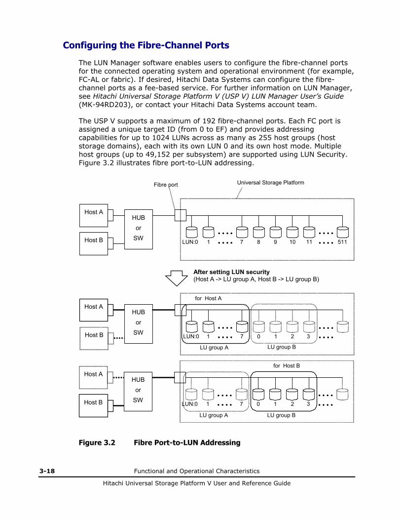
3-18 Functional and Operational Characteristics
Hitachi Universal Storage Platform V User and Reference Guide
Configuring the Fibre-Channel Ports
The LUN Manager software enables users to configure the fibre-channel ports for the connected operating system and operational environment (for example, FC-AL or fabric). If desired, Hitachi Data Systems can configure the fibre-channel ports as a fee-based service. For further information on LUN Manager, see Hitachi Universal Storage Platform V (USP V) LUN Manager User’s Guide (MK-94RD203), or contact your Hitachi Data Systems account team.
The USP V supports a maximum of 192 fibre-channel ports. Each FC port is assigned a unique target ID (from 0 to EF) and provides addressing capabilities for up to 1024 LUNs across as many as 255 host groups (host storage domains), each with its own LUN 0 and its own host mode. Multiple host groups (up to 49,152 per subsystem) are supported using LUN Security. Figure 3.2 illustrates fibre port-to-LUN addressing.
Host A
LUN:0
Fibre port Universal Storage Platform
• • • • Host B
HUB or
SW
Host A
Host B
HUB or
SW LUN:0
LU group A LU group B
Host A
Host B
HUB or
SW
LU group A LU group B
After setting LUN security (Host A -> LU group A, Host B -> LU group B)
1 7 8 9 10 11 511 • • • •
• • • •
• • • • • • • •
• • • •
1 7 0 1 2 3 • • • • • • • •
LUN:0 1 7 0 1 2 3 • • • • • • • • • • • • • • • •
for Host A
for Host B
Figure 3.2 Fibre Port-to-LUN Addressing
Functional and Operational Characteristics 3-19
Hitachi Universal Storage Platform V User and Reference Guide
Virtual LVI/LUN Devices
The Virtual LVI/LUN software enables users to configure multiple custom volumes (LVIs or LUs) under a single LDEV. Open-system users define Virtual LVI/LUN devices by size in MB* (minimum device size = 35 MB). Mainframe users define Virtual LVI/LUN devices by number of cylinders.
*Note: Storage capacities for LUs on the USP V are calculated based on the following values: 1 KB = 1,024 bytes, 1 MB = 1,0242 bytes, 1 GB = 1,0243 bytes, 1 TB = 1,0244 bytes. (Storage capacities for HDDs on the USP V are based on 1,000 instead of 1,024.)
LUN Expansion (LUSE) Devices
The LUSE software enables users to configure size-expanded LUs by concatenating multiple LUs to form a single LU. LUSE devices are identified by the type and number of LUs which have been joined to form the LUSE device. For example, an OPEN-V*15 LUSE device is composed of 15 OPEN-V LUs.
Modes and Mode Options for Host Groups and iSCSI Targets
The USP V supports connection of multiple server hosts of different platforms to each of its ports. When configuring your system, you must group server hosts connected to each port by host groups (FC) or by target (iSCSI). For example, if Solaris hosts and Windows hosts are connected to a fibre port, you must create a host group for the Solaris hosts and another host group for the Windows hosts, and you must assign the appropriate host group mode and options to each group. The modes and mode options provide enhanced compatibility with supported platforms and environments. The management software for the USP V (for example, Storage Navigator, HiCommand Device Manager) allows you to create host groups and iSCSI targets and assign modes and options to the host groups and iSCSI targets on the USP V.
For further information on the host group modes and host group mode options, see the Hitachi Universal Storage Platform V V (USP V) LUN Manager User’s Guide (MK-94RD203).
Failover and SNMP Support
The USP V supports industry-standard products and functions which provide host and/or application failover, I/O path failover, and logical volume management (LVM), including Hitachi Dynamic Link Manager, VERITAS Cluster® Server, Sun Cluster, VERITAS Volume Manager/DMP, HP MC/ServiceGuard, HACMP, Microsoft Cluster Server. For the latest information on failover and LVM product releases, availability, and compatibility, please contact your Hitachi Data Systems account team.
3-20 Functional and Operational Characteristics
Hitachi Universal Storage Platform V User and Reference Guide
The USP V also supports the industry-standard simple network management protocol (SNMP) for remote subsystem management from the UNIX/PC server host. SNMP is used to transport management information between the subsystem and the SNMP manager on the host. The SNMP agent for the USP V sends status information to the host(s) when requested by the host or when a significant event occurs.
Share-Everything Architecture
The USP V’s global cache provides a “share-everything” architecture that enables any fibre-channel port to have access to any LU in the subsystem. In the USP V, each LU can be assigned to multiple fibre-channel ports to provide I/O path failover and/or load balancing (with the appropriate middleware support such as HDLM) without sacrificing cache coherency. The LUN mapping can be performed by the user using HiCommand Device Manager or LUN Manager, or by the Hitachi Data Systems representative (fee-based configuration service).
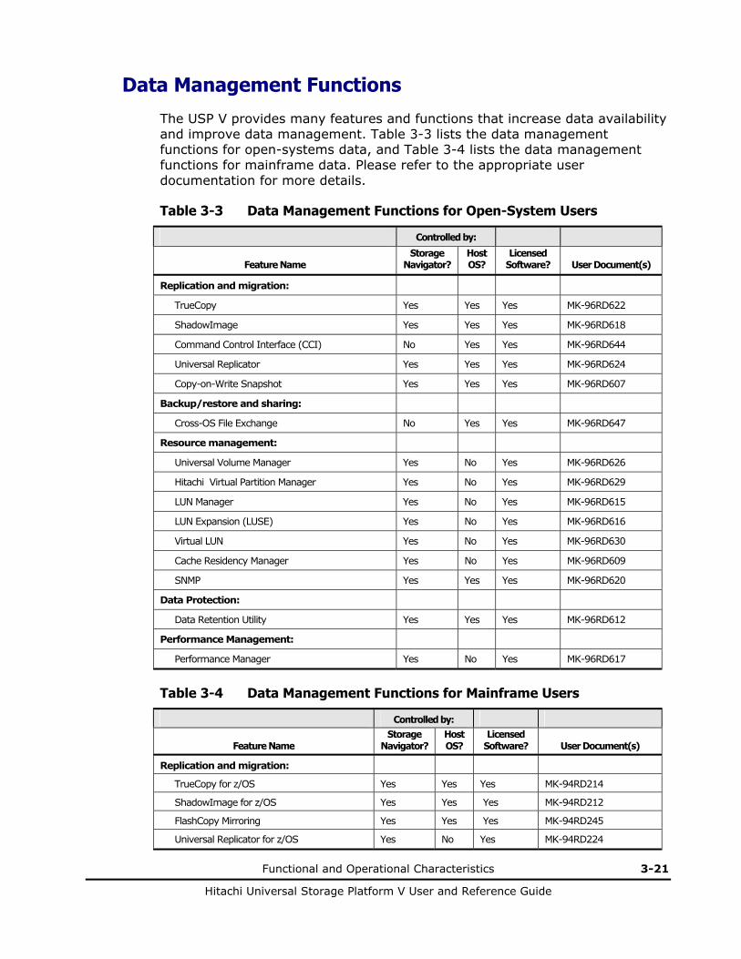
Functional and Operational Characteristics 3-21
Hitachi Universal Storage Platform V User and Reference Guide
Data Management Functions
The USP V provides many features and functions that increase data availability and improve data management. Table 3-3 lists the data management functions for open-systems data, and Table 3-4 lists the data management functions for mainframe data. Please refer to the appropriate user documentation for more details.
Table 3-3 Data Management Functions for Open-System Users
Controlled by:
Feature Name
Storage Navigator?
HostOS?
Licensed Software?
User Document(s)
Replication and migration:
TrueCopy Yes Yes Yes MK-96RD622
ShadowImage Yes Yes Yes MK-96RD618
Command Control Interface (CCI) No Yes Yes MK-96RD644
Universal Replicator Yes Yes Yes MK-96RD624
Copy-on-Write Snapshot Yes Yes Yes MK-96RD607
Backup/restore and sharing:
Cross-OS File Exchange No Yes Yes MK-96RD647
Resource management:
Universal Volume Manager Yes No Yes MK-96RD626
Hitachi Virtual Partition Manager Yes No Yes MK-96RD629
LUN Manager Yes No Yes MK-96RD615
LUN Expansion (LUSE) Yes No Yes MK-96RD616
Virtual LUN Yes No Yes MK-96RD630
Cache Residency Manager Yes No Yes MK-96RD609
SNMP Yes Yes Yes MK-96RD620
Data Protection:
Data Retention Utility Yes Yes Yes MK-96RD612
Performance Management:
Performance Manager Yes No Yes MK-96RD617
Table 3-4 Data Management Functions for Mainframe Users
Controlled by:
Feature Name Storage
Navigator? Host OS?
Licensed Software?
User Document(s)
Replication and migration:
TrueCopy for z/OS Yes Yes Yes MK-94RD214
ShadowImage for z/OS Yes Yes Yes MK-94RD212
FlashCopy Mirroring Yes Yes Yes MK-94RD245
Universal Replicator for z/OS Yes No Yes MK-94RD224
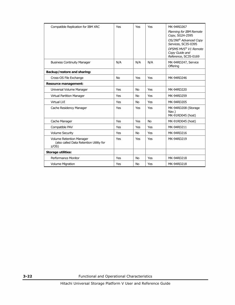
3-22 Functional and Operational Characteristics
Hitachi Universal Storage Platform V User and Reference Guide
Compatible Replication for IBM XRC Yes Yes Yes MK-94RD267
Planning for IBM Remote Copy, SG24-2595
OS/390® Advanced Copy Services, SC35-0395
DFSMS MVS® V1 Remote Copy Guide and Reference, SC35-0169
Business Continuity Manager N/A N/A N/A MK-94RD247, Service Offering
Backup/restore and sharing:
Cross-OS File Exchange No Yes Yes MK-94RD246
Resource management:
Universal Volume Manager Yes No Yes MK-94RD220
Virtual Partition Manager Yes No Yes MK-94RD259
Virtual LVI Yes No Yes MK-94RD205
Cache Residency Manager Yes Yes Yes MK-94RD208 (Storage Nav.) MK-91RD045 (host)
Cache Manager Yes Yes No MK-91RD045 (host)
Compatible PAV Yes Yes Yes MK-94RD211
Volume Security Yes No Yes MK-94RD216
Volume Retention Manager (also called Data Retention Utility for z/OS)
Yes Yes Yes MK-94RD219
Storage utilities:
Performance Monitor Yes No Yes MK-94RD218
Volume Migration Yes No Yes MK-94RD218
Functional and Operational Characteristics 3-23
Hitachi Universal Storage Platform V User and Reference Guide
Data Replication and Migration
The following sections describe the data replication and migration features of the Hitachi USP V storage system.
Hitachi TrueCopy
Hitachi TrueCopy enables open-system users to perform synchronous and/or asynchronous remote copy operations between USP Vs. The user can create, split, and resynchronize LU pairs. TrueCopy also supports a “takeover” command for remote host takeover (with the appropriate middleware support). Once established, TrueCopy operations continue unattended and provide continuous, real-time data backup. Remote copy operations are non-disruptive and allow the primary TrueCopy volumes to remain online to all hosts for both read and write I/O operations. TrueCopy operations can be performed between USP Vs and between USP V and 9900V/9900 subsystems.
Hitachi TrueCopy supports both fibre-channel and serial (ESCON) interface connections between the main and remote USP Vs. For fibre-channel connection, TrueCopy operations can be performed across distances of up to 30 km (18.6 miles) using single-mode longwave optical fibre cables in a switch configuration. For serial interface connection, TrueCopy operations can be performed across distances of up to 43 km (26.7 miles) using standard ESCON support. Long-distance solutions are provided, based on user requirements and workload characteristics, using approved channel extenders and communication lines.
Hitachi TrueCopy for z/OS
Hitachi TrueCopy for z/OS enables mainframe (z/OS, S/390) users to perform synchronous and asynchronous remote copy operations between USP Vs. Hitachi TrueCopy for z/OS can be used to maintain copies of data for backup or duplication purposes. Once established, TrueCopy for z/OS operations continue unattended and provide continuous, real-time data backup. Remote copy operations are non-disruptive and allow the primary TrueCopy volumes to remain online to all hosts for both read and write I/O operations.
Hitachi TrueCopy for z/OS also supports both serial (ESCON) and fibre-channel interface connections between the main and remote USP versus Remote copy operations can be performed between USP Vs and between USP V and 9900V/9900 subsystems.

3-24 Functional and Operational Characteristics
Hitachi Universal Storage Platform V User and Reference Guide
Hitachi ShadowImage
Hitachi ShadowImage enables open-system users to maintain system-internal copies of LUs for purposes such as data backup or data duplication. The RAID-protected duplicate LUs (up to nine) are created within the same USP V as the primary LU at hardware speeds. Once established, ShadowImage operations continue unattended to provide asynchronous internal data backup. ShadowImage operations are non-disruptive; meaning, the primary LU of each ShadowImage pair remains available to all hosts for both read and write operations during normal operations. Usability is further enhanced through a resynchronization capability that reduces data duplication requirements and backup time, thereby increasing user productivity. ShadowImage also supports reverse resynchronization for maximum flexibility.
ShadowImage operations can be performed in conjunction with Hitachi TrueCopy operations to provide multiple copies of critical data at both primary and remote sites. ShadowImage also supports the Virtual LVI/LUN and Cache Residency Manager features of the USP V, ensuring that all user data can be duplicated by ShadowImage operations.
Hitachi ShadowImage for z/OS
Hitachi ShadowImage for z/OS enables mainframe (z/OS, S/390) users to create high-performance copies of source LVIs for testing or modification while benefiting from full RAID protection for the ShadowImage copies. The ShadowImage copies can be available to the same or different logical partitions (LPARs) as the original volumes for read and write I/Os. ShadowImage allows the user to create up to three copies of a single source LVI and perform updates in either direction, either from the source LVI to the ShadowImage copy or from the copy back to the source LVI. When used in conjunction with either TrueCopy for z/OS or XRC Replication, ShadowImage for z/OS enables users to maintain multiple copies of critical data at both primary and remote sites. ShadowImage also supports the Virtual LVI/LUN and Cache Residency Manager features, ensuring that all user data can be duplicated by ShadowImage operations.
The ShadowImage – FlashCopy option provides support for and compatibility with the IBM FlashCopy data replication feature. The ShadowImage – FlashCopy option establishes pairs so that the copy of the S-VOL data can be virtually or physically created on the T-VOL. Once the pairs have been established, it is possible to specify Read/Write operation from the host to virtual data on the T-VOL or physical data on the S-VOL.

Functional and Operational Characteristics 3-25
Hitachi Universal Storage Platform V User and Reference Guide
Command Control Interface (CCI)
Hitachi Command Control Interface (CCI) enables users to perform the following data replication and data protection operations on the USP V by issuing commands from the UNIX/PC server host to the subsystem:
• TrueCopy
• ShadowImage
• Data Retention Utility
• Universal Replicator
• Copy-on-Write Snapshot
• Database Validator
CCI interfaces with the system software and high-availability (HA) software on the server host as well as the USP V Storage Navigator software. The CCI software provides failover and other functions such as backup commands to allow mutual hot standby in cooperation with the failover product on the server (e.g., MC/ServiceGuard, FirstWatch, HACMP).
CCI also supports a scripting function that allows users to define multiple operations in a script (text) file. Using CCI scripting, you can set up and execute a large number of commands in a short period of time while integrating host-based high-availability control over remote copy operations.
Universal Replicator, Universal Replicator for z/OS
Universal Replicator (UR) provides a RAID storage-based hardware solution for disaster recovery which enables fast and accurate system recovery. Once UR operations are established over dedicated fibre-channel remote copy connections, duplicate copies of data are automatically maintained for backup and disaster recovery purposes. During normal UR operations, the primary data volumes remain online to all hosts and continue to process both read and write I/O operations. In the event of a disaster or system failure, the secondary copy of data can be rapidly invoked to allow recovery with a very high level of data integrity. UR can also be used for data duplication and migration tasks.
Universal Replicator represents a unique and outstanding disaster recovery solution for large amounts of data which span multiple volumes. The UR group-based update sequence consistency solution enables fast and accurate database recovery, even after a “rolling” disaster, without the need for time-consuming data recovery procedures. The UR journal groups (volume groups) at the secondary site can be recovered with full update sequence consistency, but the updates will be behind the primary site due to the asynchronous remote copy operations. Universal Replicator provides update sequence consistency for user-defined journal groups (e.g., large databases) as well as protection for write-dependent applications in the event of a disaster.

3-26 Functional and Operational Characteristics
Hitachi Universal Storage Platform V User and Reference Guide
Copy-on-Write Snapshot
Copy-on-Write (COW) Snapshot provides ShadowImage functionality using less capacity of the disk subsystem and less time for processing than ShadowImage. COW Snapshot enables you to create copy pairs, just like ShadowImage, consisting of primary volumes (P-VOLs) and secondary volumes (S-VOLs). The COW Snapshot P-VOLs are logical volumes (OPEN-V LDEVs), but the COW Snapshot S-VOLs are virtual volumes (V-VOLs) with pool data stored in memory.
Copy-on-Write Snapshot is recommended for copying and managing data in a short time with reduced cost. However, since only some of the P-VOL data is copied by COW Snapshot, the data stored in the S-VOL is not guaranteed in certain cases (for example, physical P-VOL failure). ShadowImage copies the entire P-VOL to the S-VOL, so even if a physical failure occurs, the P-VOL data can be recovered using the S-VOL. ShadowImage provides higher data integrity than COW Snapshot, so you should consider the use of ShadowImage when data integrity is more important than the copy speed or the capacity of the disk subsystem.
Compatible Replication for IBM XRC
The Compatible Replication for IBM XRC asynchronous remote copy feature of the USP V is functionally compatible with IBM Extended Remote Copy (XRC, XRC3). XRC Replication provides asynchronous remote copy operations for maintaining duplicate copies of mainframe data for data backup purposes. Once established, XRC operations continue unattended to provide continuous data backup. XRC operations are non-disruptive and allow the primary XRC Replication volumes to remain online to the host(s) for both read and write I/O operations. For XRC Replication operations, there is no distance limit between the primary and remote disk subsystems. XRC Replication is also compatible with the DFSMS data mover that is common to the XRC environment.
XRC Replication operations are performed in the same manner as XRC operations. The user issues standard XRC TSO commands from the mainframe host system directly to the USP V. For enhanced usability, XRC Replication settings can now be configured using the XRC remote console (Storage Navigator) software. XRC Replication can be used as an alternative to Hitachi TrueCopy for z/OS for mainframe data backup and disaster recovery planning. However, XRC Replication requires host processor resources that may be significant for volumes with high-write activity. The Data Mover utility may run in either the primary host or the optional remote host.

Functional and Operational Characteristics 3-27
Hitachi Universal Storage Platform V User and Reference Guide
Backup/Restore and Sharing
The following sections describe the data backup/restore and cross-platform data sharing features of the Hitachi USP V storage system.
Cross-OS File Exchange
Cross-OS File Exchange (formerly Hitachi RapidXchange) enables the user to transfer data between mainframe and open-system platforms using the ExSA channels. Cross-OS File Exchange enables high-speed data transfer without requiring network communication links or tape. Data transfer is performed over the Cross-OS File Exchange volumes, which are shared devices that appear to the mainframe host as 3390 LVIs and to the open-system host as OPEN LUs. To provide the greatest platform flexibility for data transfer, the Cross-OS File Exchange volumes are accessed from the open-system host using SCSI raw device mode.
Cross-OS File Exchange allows the open-system host to read from and write to mainframe sequential datasets using the Cross-OS File Exchange volumes. The Cross-OS File Exchange volumes must be formatted as 3390-3A/B/C LVIs. The -A LVIs can be used for open-to-mainframe and/or mainframe-to-open Cross-OS File Exchange, the -B LVIs are used for mainframe-to-open Cross-OS File Exchange, and the -C LVIs are used for open-to-mainframe Cross-OS File Exchange. Cross-OS File Exchange also supports OPEN-x-FX devices to provide open-to-open Cross-OS File Exchange operations for USP Vs.
The Cross-OS File Exchange software enables the open-system host to read from and write to individual mainframe datasets. The Cross-OS File Exchange software is installed on the open-system host and includes the File Conversion Utility (FCU) and the File Access Library (FAL). FCU allows the user to set up and perform file conversion operations between mainframe sequential datasets and open-system flat files. The FAL is a library of C-language functions that allows open-system programmers to read from and write to mainframe sequential datasets on the Cross-OS File Exchange volumes.

3-28 Functional and Operational Characteristics
Hitachi Universal Storage Platform V User and Reference Guide
Resource Management
The following sections describe the resource management features of the Hitachi USP V storage system.
Universal Volume Manager
Universal Volume Manager is a new feature introduced on the USP V that enables users to realize the virtualization of the storage subsystem. Users can connect other subsystems to the USP V and access the data on the external subsystem over virtual devices on the USP V. Functions such as TrueCopy and Cache Residency can be performed on the external data. External subsystems can be connected to the USP V’s external ports over a switch using fibre-channel interface, and external volumes are mapped to virtual volumes on the USP V.
Virtual Partition Manager
The USP V can connect to multiple hosts and can be shared by multiple users, which can result in conflicts among users. For example, if a host issues many I/O requests, the I/O performance of other hosts may decrease. Other difficulties can occur if storage administrators issue conflicting commands or perform operations (for example, LUSE or VLL) on the same volume at the same time.
Virtual Partition Manager has two main functions: Storage Logical Partition (SLPR), and Cache Logical Partition (CLPR). Storage Logical Partition allows you to allocate the subsystem resources into multiple virtual subsystems, each of which can only be accessed by users assigned to that partition. This prevents usage conflicts. Cache Logical Partition allows you to create multiple virtual cache memories, each allocated to different host(s). This prevents contention for cache memory.
LUN Manager
LUN Manager enables users to configure logical volumes and ports for operation with UNIX and PC server hosts and modify the configuration as needed. Using LUN Manager, you can define I/O paths from hosts to logical volumes, set the host modes for the FC ports, set the fibre topology (for example, FC-AL, fabric), configure host groups (host storage domains), and define command devices for CCI operations.

Functional and Operational Characteristics 3-29
Hitachi Universal Storage Platform V User and Reference Guide
LUN Expansion (LUSE)
LUN Expansion allows users to concatenate multiple LUs into single volumes to enable open-system hosts to access the data on the entire USP V using fewer logical units. LUSE allows host operating systems that have restrictions on the number of LUs per interface to access larger amounts of data. The maximum size for a LUSE volume is 60 TB.
Virtual LVI/LUN
Virtual LVI/LUN allows users to convert single volumes (LUs or LVIs) into multiple smaller volumes to improve data access performance. Using the Virtual LVI/LUN software, users assign a logical address and a specific number of MB (for open-systems devices) or cylinders/tracks (for mainframe devices) to each custom LVI/LU.
Virtual LVI/LUN improves data access performance by reducing logical device contention as well as host I/O queue times, which can occur when several frequently accessed files are located on a single volume. Multiple LVI/LU types can be configured within each array group. Virtual LVI/LUN enables the user to more fully utilize the physical storage capacity of the USP V, while reducing the amount of administrative effort required to balance I/O workloads. When Virtual LVI/LUN is used in conjunction with Cache Residency Manager, the user can achieve even better data access performance than when either Virtual LVI/LUN or Cache Residency Manager is used alone.
Cache Residency Manager
Cache Residency Manager (formerly FlashAccess) allows users to store specific data in cache memory. Cache Residency Manager increases the data access speed for the cache-resident data by enabling read and write I/Os to be performed at front-end host data transfer speeds. The Cache Residency Manager cache areas (called cache extents) are dynamic and can be added and deleted at any time. The USP V supports up to 1024 addressable cache extents.
Cache Residency Manager operations can be performed for data on open-system LUs as well as mainframe LVIs (for example, 3390-9), including custom (VLL and LUSE) volumes. Use of Cache Residency Manager in conjunction with the Virtual LVI/LUN feature will achieve better performance improvements than when either of these options is used individually.
3-30 Functional and Operational Characteristics
Hitachi Universal Storage Platform V User and Reference Guide
Cache Manager
Cache Manager enables users to perform Cache Residency Manager operations on mainframe LVIs by issuing commands from the mainframe host system to the USP V.
Compatible PAV
Compatible PAV (formerly Hitachi PAV) enables the mainframe host system to issue multiple I/O requests in parallel to single logical devices (LDEVs) in the USP V. Compatible PAV can provide substantially faster host access to the mainframe data stored in the USP V. The Workload Manager (WLM) host software function enables the mainframe host to utilize the USP V’s Compatible PAV functionality. The USP V supports both static and dynamic PAV functionality.

Functional and Operational Characteristics 3-31
Hitachi Universal Storage Platform V User and Reference Guide
Data Protection
The following sections describe the data protection features of the Hitachi USP V storage system.
LUN Security
LUN Security allows users to restrict LU accessibility to an open-systems host using the host’s World Wide Name (WWN). You can set an LU to communicate only with one or more specified WWNs, allowing you to limit access to that LU to specified open-system host(s). This feature prevents other open-systems hosts from either seeing the secured LU or accessing the data contained on it. The LUN Manager software enables you to configure LUN Security operations on the USP V.
LUN Security can be activated on any installed fibre-channel port, and can be turned on or off at the port level. If you enable LUN Security on a particular port, that port will be restricted to a particular host or group of hosts. You can assign a WWN to as many ports as you want, and you can assign more than one WWN to each port. You can also change the WWN access for any port without disrupting the settings of that port.
Because up to 255 WWNs can access each port and the same WWNs may go to additional ports in the same subsystem, LUN Manager allows you to create host groups (host storage domains), so you can more easily manage your USP V subsystem. You assign the hosts (WWNs) to host groups and then associate the desired LUs with each host group. Each host in the host group has access to the LU(s) associated with that group.
Volume Security
Volume Security (formerly SANtinel-S/390) allows users to restrict mainframe (z/OS, S/390) host access to the logical devices (LDEVs) on the USP V. Each LDEV can be set to communicate only with user-selected host(s). Volume Security prevents other hosts from seeing the secured LDEV and from accessing the data contained on the secured LDEV. The licensed Volume Security software on the USP V Storage Navigator displays the volume security information and allows you to perform volume security operations. The Volume Security Port option can be used to specify the disk subsystem ports that hosts can use to access logical volumes.
3-32 Functional and Operational Characteristics
Hitachi Universal Storage Platform V User and Reference Guide
Database Validator
The Database Validator feature is designed for the Oracle® database platform to prevent data corruption between the database and the storage subsystem. Database Validator prevents corrupted data blocks generated in the database-to-storage subsystem infrastructure from being written onto the storage disk. The combination of networked storage and database management software has a risk of data corruption while writing data on the storage. This data corruption rarely occurs; however, once corrupted data is written into storage, it can be difficult and time-consuming to detect the underlying cause, restore the system, and recover the database. Database Validator helps prevent corrupted data environments and minimizes risk and potential costs in backup, restore, and recovery operations. Database Validator combined with the Oracle9i Database product provides a resilient system that can operate for 24 hours a day, 365 days a year to provide the uptime required by enterprises today.
The USP V supports parameters for validation checking at the volume level, and these parameters are set through the USP V command device using the Command Control Interface (CCI) software. CCI supports commands to set and verify these parameters for validation checking. Once validation checking is turned on, all write operations to the specified volume must have valid Oracle checksums. CCI reports a validation check error to the syslog file each time an error is detected.
Note: Database Validator requires the CCI software product and a separate license key. Database Validator is not controlled via the Storage Navigator remote console software.
Data Retention Utility
Data Retention Utility (formerly Open LDEV Guard) enables you to prevent writing to specified volumes by the USP V guarding the volumes. Data Retention Utility is similar to the Database Validator feature, setting a guarding attribute to the specified LU.
The USP V supports parameters for guarding at the volume level. You can set and verify these parameters for guarding of open volumes using either the USP V Storage Navigator software or the Command Control Interface (CCI) software on the host. Once guarding is enabled, the USP V conceals the target volumes from SCSI commands (for example, SCSI Inquiry, SCSI Read Capacity), prevents reading and writing to the volume, and protects the volume from being used as a copy volume (in other words, TrueCopy and ShadowImage paircreate operation fails).
Functional and Operational Characteristics 3-33
Hitachi Universal Storage Platform V User and Reference Guide
Volume Retention Manager
Volume Retention Manager (also Data Retention Utility for z/OS) (formerly LDEV Guard) allows you to protect your data from I/O operations performed by mainframe hosts. Volume Retention Manager enables you to assign an access attribute to each logical volume to restrict read and/or write operations. Using Volume Retention Manager, you can prevent unauthorized access to your sensitive data.
Volume Shredder
Volume shredding allows you to overwrite all of the data on a logical volume with dummy data. Volume shredding is available for both mainframe and open-system data. You can configure volume shredding to overwrite volumes up to eight times (recommended minimum is three times). Volume Shredding is a Virtual LVI/LUN function that is licensed separately.
Note: For details on volume shredding, see the LUN Expansion and Virtual LVI/LUN User’s Guide (MK-94RD205), or contact your Hitachi Data Systems account team.

3-34 Functional and Operational Characteristics
Hitachi Universal Storage Platform V User and Reference Guide
Performance Management
The following sections describe the performance management features of the Hitachi USP V storage system.
Hitachi Performance Monitor
Hitachi Performance Monitor provides detailed monitoring and collection of USP V usage and performance statistics. Volume Migration and Server Priority Manager use the data collected by Performance Monitor to identify and resolve bottlenecks of activity.
Volume Migration
Volume Migration (formerly CruiseControl) enables users to optimize their data storage and retrieval on the USP V. Volume Migration analyzes detailed information on the usage of the USP V’s resources and tunes the USP V automatically by migrating logical volumes within the subsystem according to detailed user-specified parameters. Volume Migration tuning operations can be used to resolve bottlenecks of activity and optimize volume allocation. Volume Migration operations are completely non-disruptive – the data being migrated can remain online to all hosts for read and write I/O operations throughout the entire volume migration process. Volume Migration also supports manual volume migration operations and estimates performance improvements prior to migration to assist you in tuning the USP V for your operational environment.
Volume Migration provides the following major benefits for the user:
• Load balancing of subsystem resources
• Optimizing disk drive access patterns
Note: For details on Volume Migration, see the Performance Manager User’s Guide (MK-94RD218), or contact your Hitachi Data Systems account team.
Server Priority Manager
Server Priority Manager (formerly Priority Access) allows open-system users to designate prioritized ports (for example, for production servers) and non-prioritized ports (for example, for development servers) and set thresholds and upper limits for the I/O activity of these ports. Server Priority Manager enables users to tune the performance of the development server without affecting production server performance.
Note: For details on Server Priority Manager, see the Performance Manager User’s Guide (MK-94RD218), or contact your Hitachi Data Systems account team.
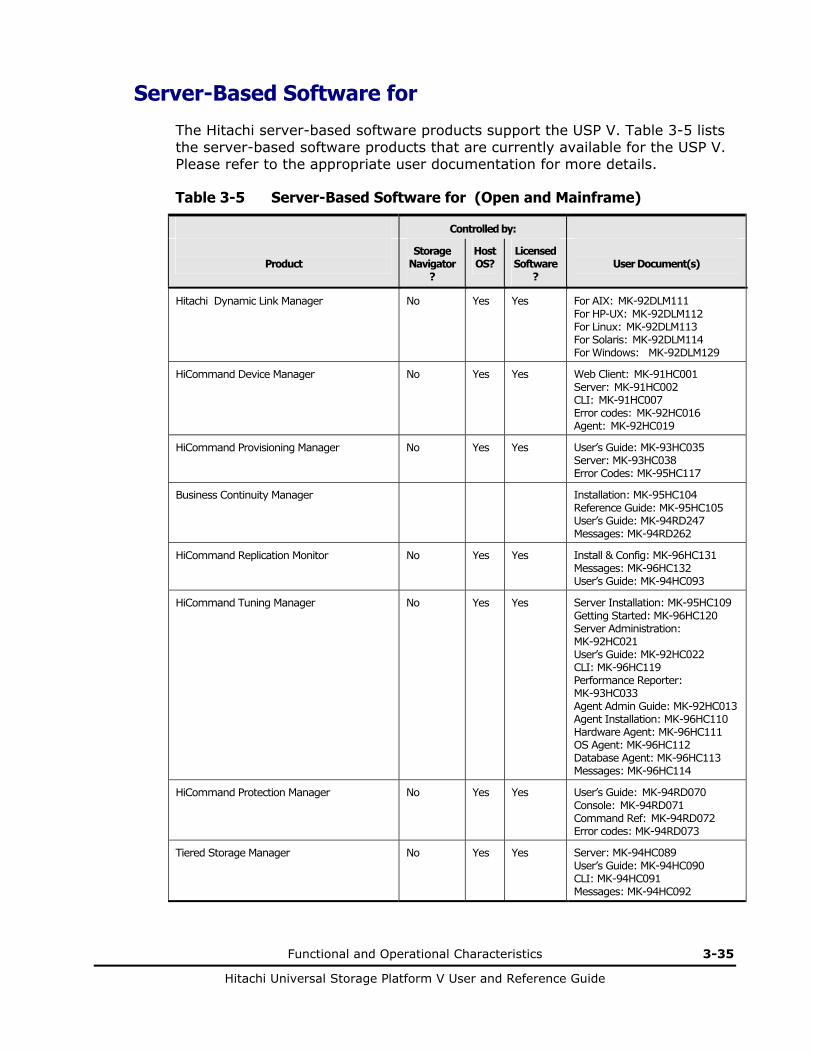
Functional and Operational Characteristics 3-35
Hitachi Universal Storage Platform V User and Reference Guide
Server-Based Software for
The Hitachi server-based software products support the USP V. Table 3-5 lists the server-based software products that are currently available for the USP V. Please refer to the appropriate user documentation for more details.
Table 3-5 Server-Based Software for (Open and Mainframe)
Controlled by:
Product
Storage Navigator
?
HostOS?
Licensed Software
?
User Document(s)
Hitachi Dynamic Link Manager No Yes Yes For AIX: MK-92DLM111 For HP-UX: MK-92DLM112 For Linux: MK-92DLM113 For Solaris: MK-92DLM114 For Windows: MK-92DLM129
HiCommand Device Manager No Yes Yes Web Client: MK-91HC001 Server: MK-91HC002 CLI: MK-91HC007 Error codes: MK-92HC016 Agent: MK-92HC019
HiCommand Provisioning Manager No Yes Yes User’s Guide: MK-93HC035 Server: MK-93HC038 Error Codes: MK-95HC117
Business Continuity Manager Installation: MK-95HC104 Reference Guide: MK-95HC105 User’s Guide: MK-94RD247 Messages: MK-94RD262
HiCommand Replication Monitor No Yes Yes Install & Config: MK-96HC131 Messages: MK-96HC132 User’s Guide: MK-94HC093
HiCommand Tuning Manager No Yes Yes Server Installation: MK-95HC109 Getting Started: MK-96HC120 Server Administration: MK-92HC021 User’s Guide: MK-92HC022 CLI: MK-96HC119 Performance Reporter: MK-93HC033 Agent Admin Guide: MK-92HC013 Agent Installation: MK-96HC110 Hardware Agent: MK-96HC111 OS Agent: MK-96HC112 Database Agent: MK-96HC113 Messages: MK-96HC114
HiCommand Protection Manager No Yes Yes User’s Guide: MK-94RD070 Console: MK-94RD071 Command Ref: MK-94RD072 Error codes: MK-94RD073
Tiered Storage Manager No Yes Yes Server: MK-94HC089 User’s Guide: MK-94HC090 CLI: MK-94HC091 Messages: MK-94HC092
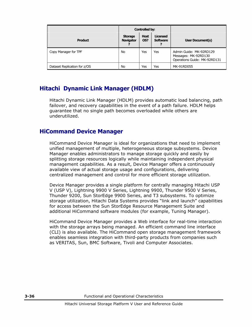
3-36 Functional and Operational Characteristics
Hitachi Universal Storage Platform V User and Reference Guide
Controlled by:
Product
Storage Navigator
?
HostOS?
Licensed Software
?
User Document(s)
Copy Manager for TPF No Yes Yes Admin Guide: MK-92RD129 Messages: MK-92RD130 Operations Guide: MK-92RD131
Dataset Replication for z/OS No Yes Yes MK-91RD055
Hitachi Dynamic Link Manager (HDLM)
Hitachi Dynamic Link Manager (HDLM) provides automatic load balancing, path failover, and recovery capabilities in the event of a path failure. HDLM helps guarantee that no single path becomes overloaded while others are underutilized.
HiCommand Device Manager
HiCommand Device Manager is ideal for organizations that need to implement unified management of multiple, heterogeneous storage subsystems. Device Manager enables administrators to manage storage quickly and easily by splitting storage resources logically while maintaining independent physical management capabilities. As a result, Device Manager offers a continuously available view of actual storage usage and configurations, delivering centralized management and control for more efficient storage utilization.
Device Manager provides a single platform for centrally managing Hitachi USP V (USP V), Lightning 9900 V Series, Lightning 9900, Thunder 9500 V Series, Thunder 9200, Sun StorEdge 9900 Series, and T3 subsystems. To optimize storage utilization, Hitachi Data Systems provides “link and launch” capabilities for access between the Sun StorEdge Resource Management Suite and additional HiCommand software modules (for example, Tuning Manager).
HiCommand Device Manager provides a Web interface for real-time interaction with the storage arrays being managed. An efficient command line interface (CLI) is also available. The HiCommand open storage management framework enables seamless integration with third-party products from companies such as VERITAS, Sun, BMC Software, Tivoli and Computer Associates.

Functional and Operational Characteristics 3-37
Hitachi Universal Storage Platform V User and Reference Guide
HiCommand Provisioning Manager
HiCommand Provisioning Manager works together with HiCommand Device Manager to provide the functionality to integrate, manipulate, and manage storage using provisioning plans. Provisioning Manager optimizes the deployment of Hitachi storage systems by exploiting deep knowledge of the architectures and automating the workflow to improve administrator efficiency. Designed to handle a variety of storage subsystems, Provisioning Manager simplifies storage management operations and reduces costs.
Business Continuity Manager
Business Continuity (BC) Manager (formerly Copycentral) is the storage industry’s first hardware-based solution which enables customers to make Point-in-Time (PiT) copies without quiescing the application or causing any disruption to end-user operations. BC Manager is based on Hitachi TrueCopy for z/OS Asynchronous, which is used to move large amounts of data over any distance with complete data integrity and minimal impact on performance. Hitachi TrueCopy for z/OS Asynchronous can be integrated with third-party channel extender products to address the “access anywhere” goal of data availability. Hitachi TrueCopy for z/OS Asynchronous enables production data to be duplicated over ESCON or communication lines from a main (primary) site to a remote (secondary) site that can be thousands of miles away.
BC Manager copies data between any number of primary subsystems and any number of secondary subsystems, located any distance from the primary subsystem, without using valuable server processor cycles. The copies may be of any type or amount of data and may be recorded on subsystems anywhere in the world.
BC Manager enables customers to quickly generate copies of production data for such uses as application testing, business intelligence, and disaster recovery for business continuance. For disaster recovery operations, BC Manager will maintain a duplicate of critical data, allowing customers to initiate production at a backup location immediately following an outage. This is the first time an asynchronous hardware-based remote copy solution, with full data integrity, has been offered by any storage vendor.
Hitachi TrueCopy for z/OS Asynchronous with BC Manager support is offered as an extension to Hitachi Data Systems’ data movement options and software solutions for the Hitachi USP V. Hitachi ShadowImage for z/OS can also operate in conjunction with Hitachi TrueCopy for z/OS Synchronous and Asynchronous to provide volume-level backup and additional image copies of data. This delivers an additional level of data integrity to assure consistency across sites and provides flexibility in maintaining volume copies at each site.

3-38 Functional and Operational Characteristics
Hitachi Universal Storage Platform V User and Reference Guide
HiCommand Replication Monitor
HiCommand Replication Monitor supports management of storage replication (copy pair) operations performed by storage administrators. Replication Monitor is used to view (report) the configuration, change the status, and troubleshoot copy pair issues. Replication Monitor is particularly effective in environments that include multiple storage subsystems or multiple physical locations, and in environments in which various types of volume replication functionality (such as both ShadowImage and TrueCopy) are used.
With the increase of data handled by corporate information systems, the way in which storage subsystems are used has changed, from standalone storage subsystems running in one location, to widely linked storage subsystems that span multiple data centers. As such, more importance has been placed on preparing environments for disaster recovery, in which several data centers are linked to protect data and perform system recovery.
By using Replication Monitor, users can visually check the configurations of multiple copy pairs configured across multiple storage subsystems, from the standpoint of a host, storage subsystem, or copy pair configuration definition. You can check system-wide pair statuses and then drill-down to areas where problems exist to identify failure areas and expedite recovery, and you can monitor copy pairs so that users are automatically notified over e-mail when a pair status changes or there is a failure occurrence.
HiCommand Tuning Manager
For organizations that have a large storage infrastructure and need to implement consolidated management of their storage environment, HiCommand Tuning Manager is the HiCommand software component that provides intelligent and proactive performance and capacity monitoring. Tuning Manager also provides reporting and forecasting capabilities of storage resources, integrated with key business applications, such as Oracle, so that organizations can optimize capacity and performance of their storage resources.
With HiCommand Tuning Manager, users can:
• Establish proactive monitoring of overall storage resources capacity and performance, responding to capacity crises and predicting storage capacity
• Prepare/plan resources for new database instance or file system
• Set up periodic reporting for storage charge-back costing
• Identify the source of slow application performance
• Prepare storage resources for implementation of a new enterprise application or storage consolidation

Functional and Operational Characteristics 3-39
Hitachi Universal Storage Platform V User and Reference Guide
Fully integrated with the HiCommand Management Framework and Device Manager and compliant with industry standards, the Tuning Manager module can be used with Hitachi USP V (USP V), Lightning 9900 V Series, Lightning 9900, Thunder 9500 V Series, and Thunder 9200 storage subsystems.

3-40 Functional and Operational Characteristics
Hitachi Universal Storage Platform V User and Reference Guide
HiCommand Protection Manager
The HiCommand Protection Manager software simplifies management of data replication and movement for business continuity and eases data maintenance operations, including operations for backup and restoration, by automating the associated workflow. Protection of important data is ensured with minimum interruption of processing jobs. The user can accomplish data management using simple operations without complex procedures and expertise, thus reducing the system administrator’s workload and the cost of data management.
HiCommand Tiered Storage Manager
HiCommand Tiered Storage Manager enables users to relocate (migrate) data from one volume on a storage subsystem to another volume for purposes of Data Lifecycle Management (DLM). With minimal preparation time, non-disruptive migration can be performed simply by specifying the relocation destination. Tiered Storage Manager helps to improve the efficiency of the entire data storage system by allowing users to migrate data quickly and easily to the appropriate locations based on the user’s environment and requirements.
When Tiered Storage Manager is used with the USP V, multiple storage subsystems can be controlled through a single USP V, enabling users to centrally manage different types of storage environments.
Using Tiered Storage Manager, users can ensure that frequently accessed data is stored in high-performance storage, while data that is used less frequently is stored in low-performance, low-cost storage. Users can decide to migrate data:
• When the importance of particular data changes
• When improving storage performance
• When the storage environment changes
Fully integrated with the HiCommand Management Framework and Device Manager and compliant with industry standards, Tiered Storage Manager can be used with Hitachi USP V V (USP V), Network Storage Controller, Lightning 9900 V Series, Lightning 9900, Thunder 9500 V Series, and Thunder 9200 storage subsystems.

Functional and Operational Characteristics 3-41
Hitachi Universal Storage Platform V User and Reference Guide
Copy Manager for TPF
Hitachi Copy Manager for TPF enables TPF users to control DASD copy functions on Hitachi RAID subsystems from TPF over an interface that is simple to install and use. With one TPF operator entry, the TPF user can control ShadowImage (local copy) or TrueCopy (remote copy) sessions over the entire TPF complex. Copy Manager for TPF provides the ability to establish, split, delete, or resume those sessions with one entry. As there are no TPF control program changes, Copy Manager for TPF requires minimal effort to incorporate into a TPF complex. Copy Manager for TPF can be used for applications such disaster recovery backup, checkpoints, and creation of test systems.
Dataset Replication for z/OS
Hitachi Dataset Replication for z/OS (formerly Logical Volume Divider) operates together with the ShadowImage feature. The Dataset Replication software rewrites the OS management information (VTOC, VVDS, and VTOCIX) and dataset name and creates a user catalog for a ShadowImage target volume after a split operation. The prepare, volume divide, volume unify, and volume backup functions are provided to enable use of a ShadowImage target volume.

3-42 Functional and Operational Characteristics
Hitachi Universal Storage Platform V User and Reference Guide
4
Planning for Installation and Operation 4-1
Hitachi Universal Storage Platform V User and Reference Guide
Planning for Installation and Operation
This chapter provides information for planning and preparing a site before and during installation of the Hitachi USP V. Please read this chapter carefully before beginning your installation planning. Figure 4.1 shows a physical overview of the USP V.
User Responsibilities and Safety Precautions
Dimensions, Physical Specifications, and Weight
Service Clearance, Floor Cutout, and Floor Load Rating Requirements
Electrical Specifications and Requirements for Three-Phase Subsystems
Electrical Specifications and Requirements for Single-Phase Subsystems
Cable Requirements
Channel Specifications and Requirements
Environmental Specifications and Requirements
Control Panel
Open-Systems Operations
If you would like to use any of the USP V features or software products (for example, Hitachi TrueCopy, ShadowImage), please contact your Hitachi Data Systems account team to obtain the appropriate license(s) and software license key(s).
Note: The general information in this chapter is provided to assist in installation planning and is not intended to be complete. The DKC510I/DKU505I (USP V) installation and maintenance documents used by Hitachi Data Systems personnel contain complete specifications. The exact electrical power interfaces and requirements for each site must be determined and verified to meet the applicable local regulations. For further information on site preparation for USP V installation, please contact your Hitachi Data Systems account team or the Hitachi Data Systems Support Center.

4-2 Planning for Installation and Operation
Hitachi Universal Storage Platform V User and Reference Guide
DKC
DKU-R1
(925mm)
(1,860mm)
(650mm)
(650mm)
(650mm)
(650mm)
(782mm) *1
DKU-L2
DKU-L1
DKU-R2
*1:This includes the thickness of side covers (16mm x2)
3,382mm
HDU-Box (DKU-R0)
DKC Box
Battery Box
Power Supply
Control Panel
HDU Box
FAN
Additional DKU
Figure 4.1 Physical Overview of Universal Storage Platform V

Planning for Installation and Operation 4-3
Hitachi Universal Storage Platform V User and Reference Guide
User Responsibilities and Safety Precautions
Before the USP V arrives for installation, the user must provide the following items to ensure proper installation and configuration:
• Physical space necessary for proper subsystem function and maintenance activity
• Electrical input power
• Connectors and receptacles
• Air conditioning
• Floor ventilation areas (recommended but not required)
• Cable access holes
• LAN connection (or RJ-11 analog phone line) for Hi-Track support
Safety Precautions
For safe operation of the USP V disk subsystem, please observe the following precautions:
• WARNING: Do not touch areas marked “HAZARDOUS”, even with the power off. These areas contain high-voltage power.
• Use the subsystem with the front and rear doors closed. The doors are designed for safety and protection from noise, static electricity, and EMI emissions.
• Make sure that all front and rear doors are closed before operating the subsystem. The only exceptions are during the power-up and power-down processes.
• Before performing power-down or power-up, make sure that the disk subsystem is not undergoing any maintenance and is not being used online.
• Do not place objects against the sides or bottom of the frames (air inlet), or on top of the frames (air outlet). This interferes with the flow of cooling air.
• For troubleshooting, perform only the instructions described in this manual. If you need further information, please contact Hitachi Data Systems maintenance personnel.
• In case of a problem with the subsystem, please report the exact circumstances surrounding the problem and provide as much detail as possible to expedite problem isolation and resolution.

4-4 Planning for Installation and Operation
Hitachi Universal Storage Platform V User and Reference Guide
Dimensions, Physical Specifications, and Weight
Figure 4.2 shows the physical dimensions of the Hitachi USP V (USP V). Table 4-1 lists the physical specifications for the disk controller (DKC) components of the USP V. lists the physical specifications for the disk array unit (DKU) components of the USP V.
Front
925
727
727
782
Rear
DKC
(Unit: mm)
(Unit: mm)
Front
650
627
925
627
Rear
DKU
Figure 4.2 DKC and DKU Physical Dimensions for the Universal Storage Platform V
Table 4-1 DKC Component Specifications: Weight, Dimensions
Weight Dimension (mm) No Model Number (kg)
Width Depth Height 1 DKC610I-5 386.0 782 *1 925 1,920
2 DKC-F610I-DH 90 — — —
3 DKC-F610I-DS 90 — — —
4 DKC-F610I-3PS 4.3 — — —
5 DKC-F610I-3EC 2.8 — — —
6 DKC-F610I-3UC 4.9 — — —
7 DKC-F610I-1PS 4.0 — — —
8 DKC-F610I-1EC 2.8 — — —
9 DKC-F610I-1UC 4.7 — — —

Planning for Installation and Operation 4-5
Hitachi Universal Storage Platform V User and Reference Guide
10 DKC-F610I-1PSD 4.3 — — —
11 DKC-F610I-1ECD 2.8 — — —
12 DKC-F610I-1UCD 4.7 — — —
13 DKC-F610I-APC 12 — — —
14 DKC-F610I-AB 14 — — —
15 DKC-F610I-ABX 36 — — —
16 DKC-F610I-CX 2.2 — — —
17 DKC-F610I-C4G 0.08 — — —
18 DKC-F610I-C8G 0.08 — — —
19 DKC-F610I-SX 1.2 — — —
20 DKC-F610I-S2GQ 0.08 — — —
21 DKC-F610I-S4GQ 0.08 — — —
22 DKC-F610I-CSW 1.8 — — —
23 DKC-F610I-DKA 2.6 — — —
24 DKC-F610I-SVP 4.1 — — —
25 DKC-F610I-PCI 0.3 — — —
26 DKC-F610I-R1DC 4.4 — — —
27 DKC-F610I-R1UC 5.7 — — —
28 DKC-F610I-L1DC 4.3 — — —
29 DKC-F610I-L1UC 5.8 — — —
30 DKC-F610I-MDM 0.07 — — —
31 DKC-F610I-8S 2.7 — — —
32 DKC-F610I-8MFS 3.0 — — —
33 DKC-F610I-8MFL 3.0 — — —
34 DKC-F610I-8FS 2.8 — — —
35 DKC-F610I-16FS 3.0 — — —
36 DKC-F610I-8IS 2.4 — — —
37 DKC-F610I-1FL 0.02 — — —
38 DKC-F610I-1FS 0.02 — — —
Notes:
1. This includes the thickness of side covers (16 mm × 2).
2. These options can be used for both of the DKC510I and DKU505I.
3. This is common to the option installed in DKC460I (Lightning 9900V). For use on DKC510I (USP V), bundle the extra cable.
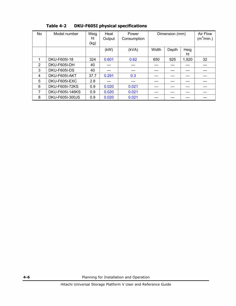
4-6 Planning for Installation and Operation
Hitachi Universal Storage Platform V User and Reference Guide
Table 4-2 DKU-F605I physical specifications
No Model number Weight
(kg)
Heat Output
Power Consumption
Dimension (mm) Air Flow (m3/min.)
(kW) (kVA) Width Depth Height
1 DKU-F605I-18 324 0.601 0.62 650 925 1,920 32 2 DKU-F605I-DH 40 — — — — — — 3 DKU-F605I-DS 40 — — — — — — 4 DKU-F605I-AKT 37.7 0.291 0.3 — — — — 5 DKU-F605I-EXC 2.8 — — — — — — 6 DKU-F605I-72KS 0.9 0.020 0.021 — — — — 7 DKU-F605I-146KS 0.9 0.020 0.021 — — — — 8 DKU-F605I-300JS 0.9 0.020 0.021 — — — —

Planning for Installation and Operation 4-7
Hitachi Universal Storage Platform V User and Reference Guide
Service Clearance, Floor Cutout, and Floor Load Rating Requirements
This section specifies the service clearance requirements (a + b) for the USP V based on the floor load rating and the clearance (c).
• Figure 4.3 shows the service clearance and floor cutout for one frame (DKC only, no DKUs). Table 4-3 shows the floor load rating requirements for this configuration.
• Figure 4.4 shows the service clearance and floor cutouts for two frames (one DKC, one DKU). Table 4-4 shows the floor load rating requirements for this configuration.
• Figure 4.5 shows the service clearance and floor cutouts for three frames (one DKC, two DKUs). Table 4-5 shows the floor load rating requirements for this configuration.
• Figure 4.6 shows the service clearance and floor cutouts for four frames (one DKC, three DKUs). Table 4-6 shows the floor load rating requirements for this configuration.
• Figure 4.7 shows the service clearance and floor cutouts for five frames (one DKC, four DKUs). Table 4-7 shows the floor load rating requirements for this configuration.
Caution: The service clearance is required for service work. Do not use this space for storage of any article to prevent damage.
Note: Actual clearances for installation should be decided after consulting with construction specialist responsible for installation building, as clearances could vary depending on the size/layout of the subsystem and building conditions.
Note: When various configurations of subsystems are arranged in a row, use the clearance values based on the maximum subsystem configuration.
Note: For efficient maintenance operations, it is recommended that clearance (c) be made as large as possible.
The following formula can be used to calculate floor loading to ensure that the weight of all equipment to be installed is adequately supported. Total area is defined as machine area plus half the service clearance.
machine weight + (15 lb/ft2 × 0.5 service clearance) + (10 lb/ft2 × total area) total area
The additional weight of the raised floor and the weight of the cables is 10 lb/ft2 (50 kg/m2) uniformly across the total area used in the calculations. When personnel and equipment traffic occur in the service clearance area, a distributed weight of 15 lb/ft2 (75 kg/m2) is allowed. This distributed weight is applied over half of the service clearance area up to a maximum of 760 mm (30 inches) from the machine.

4-8 Planning for Installation and Operation
Hitachi Universal Storage Platform V User and Reference Guide
Recommended dimension:400 ( 340 – 450 ) *4
Recommended dimension:250 ( 180 - 405 ) *4
Recommended dimension:250 ( 180 - 405 ) *4
(Unit : mm)
Floor cutout area for cables
Caster
Screw jack
Service clearance
G Grid panel (over 450mm x 450mm)
782
Front
G
G
DKC
a *1 *1b
210
65 179 52.5
785 557 450
75 189 62.5
110
67
16
200 *3 d *2
562
648
750 16c *1
2525 925
Front
925
727
727
782
800
800
Rear
DKC
Figure 4.3 DKC Service Clearance and Floor Cutout
*1 Clearance (a+b) depends on the floor load rating and clearance c. Floor load rating and required clearances are in Table 4-3. Allow clearance of 100 mm on both sides of the subsystem when the kick plates are to be attached after the subsystem is installed. However, when subsystems of the same type are to be installed adjacent to each other, clearance between the subsystems may be 100 mm.
*2 Clearance (d) must be over 350mm to open the subsystem front door. If clearance(d) is less than clearance(a), give priority to clearance(a).
*3 The side clearance on the front left side of the subsystem must be 350 mm or wider in order to open the DKC front door. However, priority should be given to the side clearance value "a" according to the load on the floor when the dimension "a" exceeds 350 mm.
*4 Dimensions in parentheses show allowable range of the floor cutout dimensions. Basically, position the floor cutout in the center of the subsystem. However, the position may be off-center, as long as the cutout allows smooth entrance of an external cable (check the relation between the positions of the cutout and the opening on the bottom plate of the subsystem) and it is within the allowable range.
*5 This dimension varies depending on the floor cutout dimensions.

Planning for Installation and Operation 4-9
Hitachi Universal Storage Platform V User and Reference Guide
Table 4-3 Floor Load Rating and Required Clearances for One Frame (DKC only)
Floor load Required clearance (a+b) m rating Clearance (c) m
(kg/m2) C=0 C=0.2 C=0.4 C=0.6 C=1.0 500 0.4 0.3 0.2 0.1 0 450 0.5 0.4 0.3 0.2 0.1 400 0.8 0.6 0.5 0.4 0.2 350 1.1 0.9 0.8 0.6 0.4 300 1.7 1.4 1.2 1.1 0.8
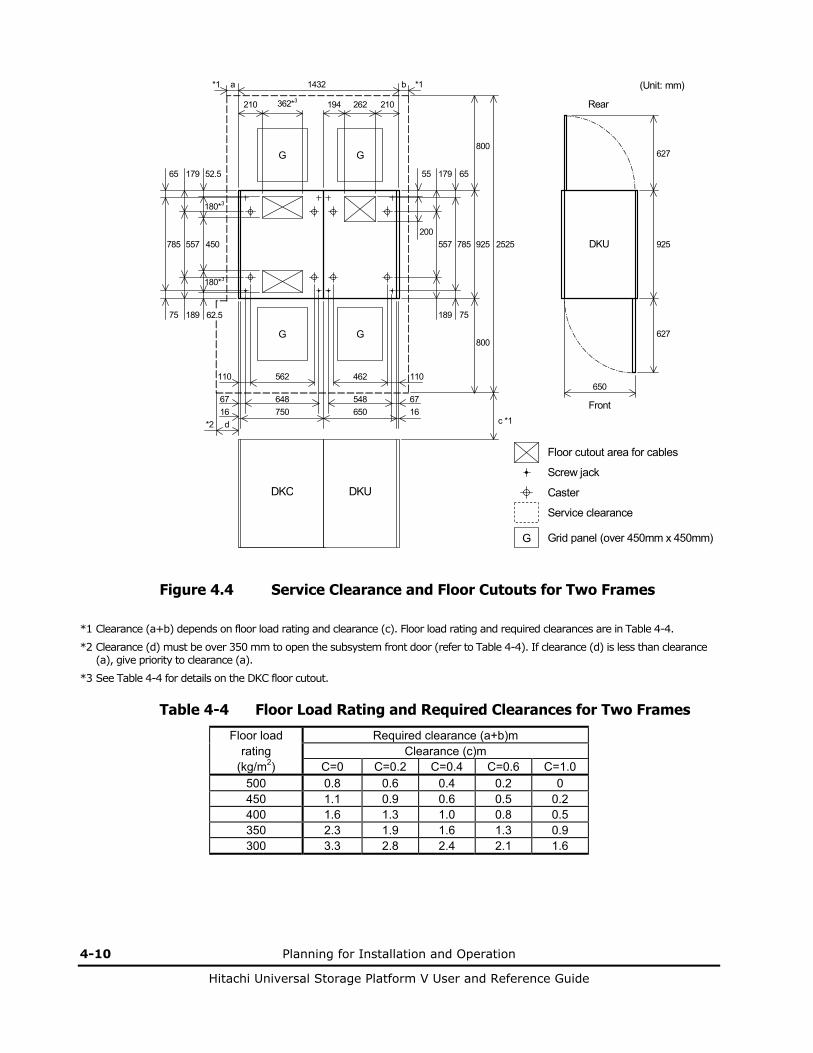
4-10 Planning for Installation and Operation
Hitachi Universal Storage Platform V User and Reference Guide
(Unit: mm) 1432
G
G
DKC
a *1 b
210
65 179 52.5
785 557 450
75 189 62.5
110
67 16 d *2
562
648 750
Floor cutout area for cables
Caster
Screw jack
Service clearance
G Grid panel (over 450mm x 450mm)
*1
362*3
G
180*3
180*3
194 262 210
G
462
548650
DKU
110
6716
55 179 65
800
200557 785 925 2525
189 75
800
c *1
Front
650
627
925
627
Rear
DKU
Figure 4.4 Service Clearance and Floor Cutouts for Two Frames
*1 Clearance (a+b) depends on floor load rating and clearance (c). Floor load rating and required clearances are in Table 4-4.
*2 Clearance (d) must be over 350 mm to open the subsystem front door (refer to Table 4-4). If clearance (d) is less than clearance (a), give priority to clearance (a).
*3 See Table 4-4 for details on the DKC floor cutout.
Table 4-4 Floor Load Rating and Required Clearances for Two Frames
Floor load Required clearance (a+b)m rating Clearance (c)m
(kg/m2) C=0 C=0.2 C=0.4 C=0.6 C=1.0 500 0.8 0.6 0.4 0.2 0 450 1.1 0.9 0.6 0.5 0.2 400 1.6 1.3 1.0 0.8 0.5 350 2.3 1.9 1.6 1.3 0.9 300 3.3 2.8 2.4 2.1 1.6

Planning for Installation and Operation 4-11
Hitachi Universal Storage Platform V User and Reference Guide
(Unit: mm)
Floor cutout area for cables
Caster Screw jack
Service clearance
G Grid panel (over 450mm x 450mm)
650
a
G G G
G G G
DKU DKU DKC
*1 2082 b *1
16 750 650 16
800
925
800
2525
c *1
Figure 4.5 Service Clearance and Floor Cutouts for Three Frames
*1. Clearance (a+b) depends on the floor load rating and clearance (c). Floor load rating and required clearances are in Table 4-5.
Table 4-5 Floor Load Rating and Required Clearances for Three Frames
Floor load Required clearance (a+b)m rating Clearance (c)m
(kg/m2) C=0 C=0.2 C=0.4 C=0.6 C=1.0 500 1.2 0.9 0.6 0.3 0.0 450 1.7 1.3 1.0 0.7 0.3 400 2.4 1.9 1.5 1.2 0.7 350 3.4 2.8 2.3 2.0 1.4 300 4.9 4.2 3.6 3.1 2.4
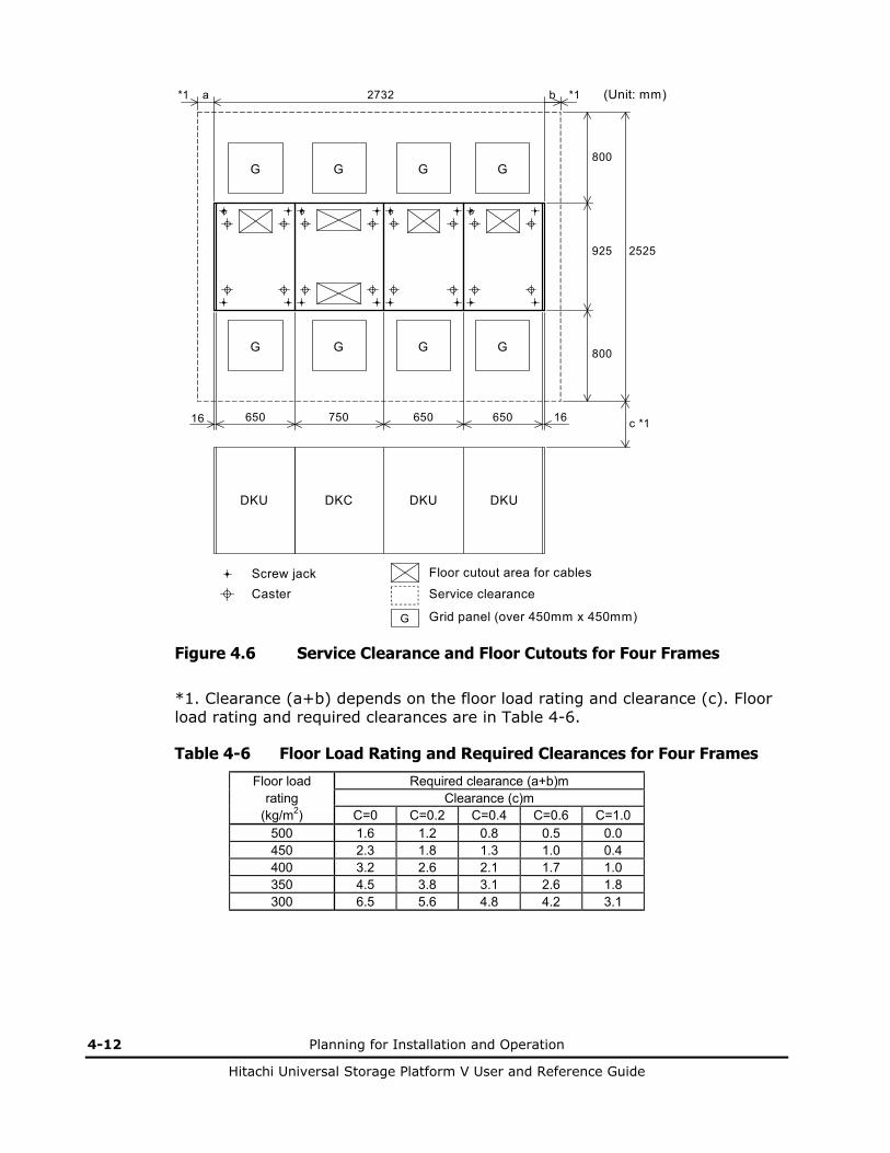
4-12 Planning for Installation and Operation
Hitachi Universal Storage Platform V User and Reference Guide
Floor cutout area for cables
Service clearance
G Grid panel (over 450mm x 450mm)
Caster Screw jack
650
a
G
*1
16
G
DKU
(Unit: mm)
DKC
2732 b *1
750 650 16
800
925
800
2525
c *1
G G G
G G G
650
DKU DKU
Figure 4.6 Service Clearance and Floor Cutouts for Four Frames
*1. Clearance (a+b) depends on the floor load rating and clearance (c). Floor load rating and required clearances are in Table 4-6.
Table 4-6 Floor Load Rating and Required Clearances for Four Frames
Floor load Required clearance (a+b)m rating Clearance (c)m
(kg/m2) C=0 C=0.2 C=0.4 C=0.6 C=1.0 500 1.6 1.2 0.8 0.5 0.0 450 2.3 1.8 1.3 1.0 0.4 400 3.2 2.6 2.1 1.7 1.0 350 4.5 3.8 3.1 2.6 1.8 300 6.5 5.6 4.8 4.2 3.1

Planning for Installation and Operation 4-13
Hitachi Universal Storage Platform V User and Reference Guide
(Unit: mm)
Floor cutout area for cables
Service clearance
G Grid panel (over 450mm x 450mm)
Caster Screw jack
650
a
G
DKC
*1 3382 b *1
16 750 650 16
800
925
800
2525
c *1
G G G G
G G G G G
650 650
DKU DKU DKU DKU
Figure 4.7 Service Clearance and Floor Cutouts for Five Frames
*1. Clearance (a+b) depend on the floor load rating and clearance c. Floor load rating and required clearances are in Table 4-7.
Table 4-7 Floor Load Rating and Required Clearances for Five Frames
Floor load Required clearance (a+b)m rating Clearance (c)m
(kg/m2) C=0 C=0.2 C=0.4 C=0.6 C=1.0 500 2.0 1.5 1.0 0.6 0.0 450 2.8 2.2 1.7 1.2 0.6 400 4.0 3.2 2.6 2.1 1.3 350 5.6 4.7 3.9 3.3 2.3 300 8.2 7.0 6.0 5.2 3.9

4-14 Planning for Installation and Operation
Hitachi Universal Storage Platform V User and Reference Guide
Electrical Specifications and Requirements for Three-Phase Subsystems
The USP V supports three-phase and single-phase power. This section provides electrical specifications and requirements for three-phase subsystems:
• Power plugs for three-phase (Europe)
• Power plugs for three-phase (USA)
• Features for three-phase
• Current rating, power plugs, receptacles, and connectors for three-phase (60 Hz only)
• Input voltage tolerances for three-phase
• Cable dimensions for 50-Hz three-phase subsystems
The AC input to the USP V subsystem has a duplex structure per AC box. When installing a subsystem, be careful to correctly connect the AC cable which connects AC box and power distribution panel. If the AC cable is not connected correctly, a system failure is caused when one of AC inputs intercept.
PDP1 PDP2 PDP2PDP1PDP2 PDP1
Connect to same PDP
AC Input Line
PDP: Power Distribution Panel *1: The output of one AC box supplies electric power to the whole DKC610I-5. *2: Since two AC input lines to which electric power is supplied in one AC Box are not redundant,
two AC input lines need to supply electric power. *3: When PDP1 breaks, since the output of one AC box cannot supply the whole DKC610I-5,
it causes a system failure.
When AC input line is connected to direct Power Facility
DKC610I-5
AC Box (3φ/30A)
AC Box (3φ/30A)
DKC HDU
DKC610I-5
AC Box(1φ/30A)
DKC HDU
AC Box(1φ/30A)
Duplex Structure
DuplexBreaker
DKC610I-5
AC Box (1φ/30A)
DKC HDU
AC Box (1φ/30A)
Wrong Connection *3
*1 *1
*2
Figure 4.8 Three-Phase AC Input, Connection to the Power Facility

Planning for Installation and Operation 4-15
Hitachi Universal Storage Platform V User and Reference Guide
Power Plugs for Three-Phase (Europe)
Figure 4.9 illustrates the power plugs for a three-phase USP V (Europe). The DKC has two (2) main disconnect devices (two main breaker CB101s for dual power lines), so that AC power of the unit can be supplied from the separate power distribution board with two (2) power supply cords. Similarly, each of the DKU-R1, DKU-R2, DKU-L1, and DKUL2 also has two (2) main disconnect devices.
Caution: The Hitachi Data Systems representative must observe all instructions in the Maintenance Manual before connecting the equipment to the power source and before servicing.
Connection of Power Supply Cord. The unit has two (2) power supply cords. Make sure to prepare the following socket receptacles and power cords between the power distribution board of the building and the power cords for the unit:
• Socket Receptacle: As shown in the following figure.
• Power Cord: Type H07RN-F or equivalent, with five 6 mm2 conductors.
Make sure to connect a power cord to the distribution box as illustrated in Figure 4.9. The wrong connection of neutral line may cause fire or damage to the equipment. To reduce the risk of wrong connection, use the approved type attachment plug and socket for power cord connection.
High leakage current may be caused between the power supply and this unit. To avoid an electric shock by high leakage current, perform the protective earth connection before the supply connections and disconnect it after the supply connections.
Requirements to Branch Circuit. This unit relies on the building installation for protection of the internal components of the equipment. Each line (R/S/T/N line) should be protected by a short-circuit protective device and by an over-current protective device rated 30 amp on building installation.
The protective device on building installation shall be comply with National Standards of the country where the units shall be installed, and if a protective device interrupts a conductor, it shall also interrupt all other supply conductors. This protection is also required for the neutral line of this unit.
Disconnection from Power Supply. The DKC has two (2) main disconnect devices (two main breaker CB101s for dual power lines). Each DKU has two (2) main disconnect devices (two main breaker CB101s for dual power lines). To remove all utility power from the unit, turn off both main disconnect device CB101s at the same time.
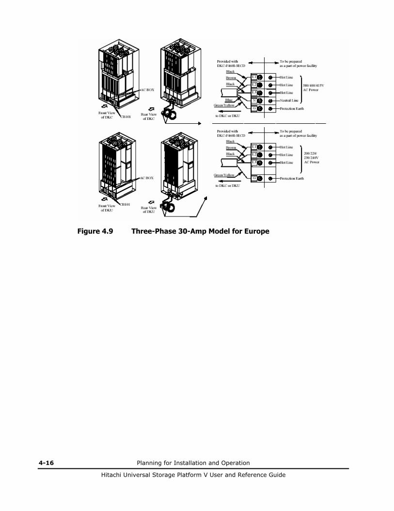
4-16 Planning for Installation and Operation
Hitachi Universal Storage Platform V User and Reference Guide
Figure 4.9 Three-Phase 30-Amp Model for Europe
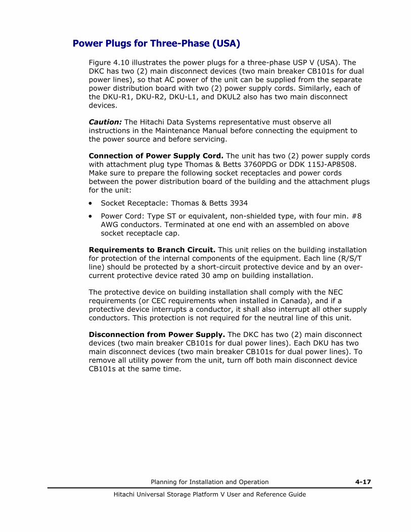
Planning for Installation and Operation 4-17
Hitachi Universal Storage Platform V User and Reference Guide
Power Plugs for Three-Phase (USA)
Figure 4.10 illustrates the power plugs for a three-phase USP V (USA). The DKC has two (2) main disconnect devices (two main breaker CB101s for dual power lines), so that AC power of the unit can be supplied from the separate power distribution board with two (2) power supply cords. Similarly, each of the DKU-R1, DKU-R2, DKU-L1, and DKUL2 also has two main disconnect devices.
Caution: The Hitachi Data Systems representative must observe all instructions in the Maintenance Manual before connecting the equipment to the power source and before servicing.
Connection of Power Supply Cord. The unit has two (2) power supply cords with attachment plug type Thomas & Betts 3760PDG or DDK 115J-AP8508. Make sure to prepare the following socket receptacles and power cords between the power distribution board of the building and the attachment plugs for the unit:
• Socket Receptacle: Thomas & Betts 3934
• Power Cord: Type ST or equivalent, non-shielded type, with four min. #8 AWG conductors. Terminated at one end with an assembled on above socket receptacle cap.
Requirements to Branch Circuit. This unit relies on the building installation for protection of the internal components of the equipment. Each line (R/S/T line) should be protected by a short-circuit protective device and by an over-current protective device rated 30 amp on building installation.
The protective device on building installation shall comply with the NEC requirements (or CEC requirements when installed in Canada), and if a protective device interrupts a conductor, it shall also interrupt all other supply conductors. This protection is not required for the neutral line of this unit.
Disconnection from Power Supply. The DKC has two (2) main disconnect devices (two main breaker CB101s for dual power lines). Each DKU has two main disconnect devices (two main breaker CB101s for dual power lines). To remove all utility power from the unit, turn off both main disconnect device CB101s at the same time.
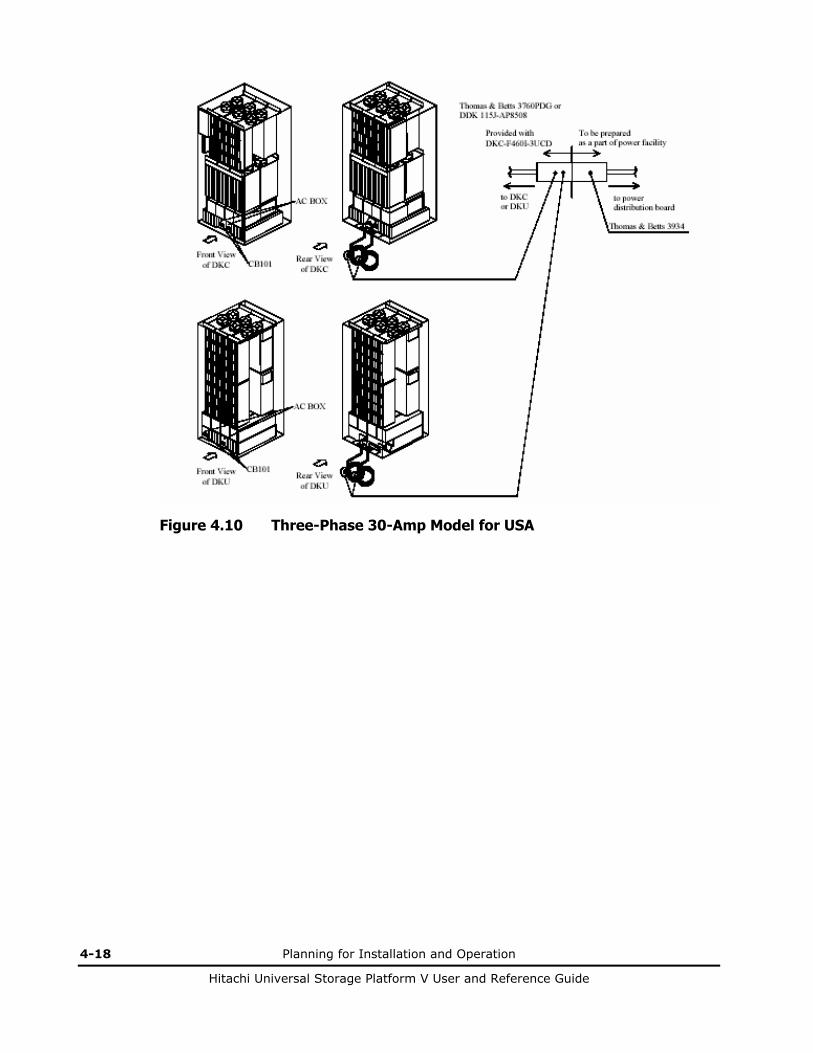
4-18 Planning for Installation and Operation
Hitachi Universal Storage Platform V User and Reference Guide
Figure 4.10 Three-Phase 30-Amp Model for USA
Planning for Installation and Operation 4-19
Hitachi Universal Storage Platform V User and Reference Guide
Features for Three-Phase
Table 4-8 lists the features for three-phase USP V subsystems. The three-phase USP V requires dual power feeds to every frame (DKC and all DKU frames).
Table 4-8 Universal Storage Platform V Three-Phase Features
Frame Feature Number
Description Comments
Controller DKC-F610I-3PS AC Box Kit for 3-Phase/30A
Required when the specification for the power supplied to the subsystem is 200V/3-phase, and a breaker capacity of power facility is 30A. The option can be used for both DKC and DKU frames. Two 30A power facilities per DKC or DKU frame are required.
Disk Array DKC-F610I-3PS AC Box Kit for 3-Phase/30A
Same as option for DKC. Two 30A power facilities per DKC or DKU frame are required.
Power Cables and Connectors for Three-Phase
Table 4-9 lists the power cables and connectors for three-phase subsystems.
The user must supply all power receptacles and connectors for the USP V. Thomas & Betts (T&B) (formerly R&S) type connectors (or Hubbell or Leviton) are recommended for 60-Hz subsystems.
Note: Each USP V disk array frame requires two power connections for power redundancy. It is strongly recommended that the second power source be supplied from a separate power boundary to eliminate source power as a possible single (non-redundant) point of failure.
Table 4-9 Power Cables and Customer-Supplied Connectors for Three-Phase
Model Part Connector Comments
DKC-F460I-3UCD
For DKC & DKU
Power Cable Unit Thomas & Betts: 3934
U.S. - Power Cable Kit / 3-Phase 30A / 60Hz
DKC-F460I-3ECD
For DKC & DKU
Power Cable Unit N/A Europe – Power Cable Kit / 3-Phase 30A / 50Hz
*Note: For information on power connection specifications for locations outside the U.S., contact the Hitachi Data Systems Support Center for the specific country.

4-20 Planning for Installation and Operation
Hitachi Universal Storage Platform V User and Reference Guide
Input Voltage Tolerances for Three-Phase
Table 4-10 lists the input voltage tolerances for the three-phase USP V subsystem. Transient voltage conditions must not exceed +15-18% of nominal and must return to a steady-state tolerance within of +6 to -8% of the normal related voltage in 0.5 seconds or less. Line-to-line imbalance voltage must not exceed 2.5%. Non-operating harmonic contents must not exceed 5%.
Table 4-10 Input Voltage Specifications for Three-Phase AC Input
Frequency Input Voltages (AC) Wiring Tolerance Remarks
60 Hz ± 0.5 Hz 200V, 208V, or 230V 3-phase, 3 wire + ground
+6% or -8%
For North America 200V
50 Hz ± 0.5 Hz 200V, 220V, 230V, or 240V
3-phase, 3 wire + ground
+6% or -8%
For Europe 200V
50 Hz ± 0.5 Hz 380V, 400V, or 415V 3-phase, 4 wire + ground
+6% or -8%
For Europe
Note: These specifications apply to the power supplied to the USP V subsystem, not to the subsystem-internal power system.
Cable Dimensions for 50-Hz Three-Phase Subsystems
Table 4-11 and Figure 4.11 show the data required for 50-Hz three-phase cable installations.
Table 4-11 Cable and Terminal Dimensions for 50-Hz Three-Phase Subsystems
Power Cable Terminal Outer Sheath
Overall Diameter Insulator
Outer Diameter Electric Wire
Cross-Section Area Internal Diameter
External Diameter
Screw Size
Model A B C D E
DKC-F460I-3ECD (30A)
18.0-24.5mm 5.2 mm 6.0 mm2 6.4 mm 12.0 mm M6
A
C
B
D E
Figure 4.11 Cable and Terminal Dimensions for 50-Hz Three-Phase Subsystems

Planning for Installation and Operation 4-21
Hitachi Universal Storage Platform V User and Reference Guide

4-22 Planning for Installation and Operation
Hitachi Universal Storage Platform V User and Reference Guide
Electrical Specifications and Requirements for Single-Phase Subsystems
The USP V supports three-phase and single-phase power. This section provides electrical specifications and requirements for single-phase subsystems:
• Power plugs for single-phase (Europe)
• Power plugs for single-phase (USA)
• Features for single-phase
• Current rating, power plugs, receptacles, and connectors for single-phase (60 Hz only)
• Input voltage tolerances for single-phase
• Cable dimensions for 50-Hz single-phase subsystems
Figure 4.12 and Figure 4.13 show the single-phase AC input power for the USP V DKC and DKU frames, respectively.
50A Breaker
50A Breaker
HDU Controller
DKC610I-5
DKC-F610I-1UC/1ECx 1set
AC Box (1φ/50A)
AC Box (1φ/50A)
DKC-F610I-1PS
Figure 4.12 Single-Phase AC Input Power (DKC)
50A breaker
50A breaker
HDU
DKU605I-18
DKC-F610I-1UC/1EC
AC Box (1φ/50A)
AC Box (1φ/50A)
DKC-F610I-1PS
Figure 4.13 Single-Phase AC Input Power (DKU)
Planning for Installation and Operation 4-23
Hitachi Universal Storage Platform V User and Reference Guide
Power Plugs for Single-Phase (Europe)
Figure 4.14 illustrates the power plugs for a single-phase USP V controller (Europe). The DKC has two (2) main disconnect devices (two main breaker CB101s for dual power lines), so that AC power of the unit can be supplied from the separate power distribution board with two (2) power supply cords. Similarly, each of the DKU-R1, DKU-R2, DKU-L1, and DKU-L2 also has two (2) main disconnect devices (two main breaker CB101s for dual power lines).
Caution: The Hitachi Data Systems representative must observe all instructions in the Maintenance Manual before connecting the equipment to the power source and before servicing.
Connection of Power Supply Cord. The unit has two power supply cords. Be sure to prepare the following socket receptacles and power cords between the power distribution board of the building and the power cords for the unit.
• Socket Receptacle: As shown in the following figure.
• Power Cord: Type H07RN-F or equivalent, with three 10 mm2 conductors.
Make sure to connect a power cord to the distribution box as illustrated in Figure 4.14. The wrong connection of neutral line may cause fire or damage to the equipment. To reduce the risk of wrong connection, you should use approved type attachment plug and socket for power cord connection.
High leakage current may be caused between the power supply and this unit. To avoid an electric shock by high leakage current, perform the protective earth connection before the supply connections and disconnect it after the supply connections.
Requirements to Branch Circuit. This unit relies on the building installation for protection of the internal components of the equipment. Each line (U/L1, N/L2 line) should be protected by a short-circuit protective device and by an over-current protective device rated 50 amp on building installation.
The protective device on building installation shall be comply with National Standards of the country where the units shall be installed, and if a protective device interrupts a conductor, it shall also interrupt all other supply conductors. This protection is also required for the neutral line of this unit.
Disconnection from Power Supply. The DKC has two (2) main disconnect devices (two main breaker CB101s for dual power lines). Each DKU has two (2) main disconnect devices (two main breaker CB101s for dual power lines). To remove all utility power from the unit, turn off both main disconnect device CB101s at the same time.

4-24 Planning for Installation and Operation
Hitachi Universal Storage Platform V User and Reference Guide
Figure 4.14 Single-Phase 50-Amp Model for Europe
Planning for Installation and Operation 4-25
Hitachi Universal Storage Platform V User and Reference Guide
Power Plugs for Single-Phase (USA)
Figure 4.15 illustrates the power plugs for a single-phase USP V controller (USA). The DKC has two (2) main disconnect devices (two main breaker CB101s for dual power lines), so that AC power of the unit can be supplied from the separate power distribution board with two (2) power supply cords. Similarly, each of the DKU-R1, DKU-R2, DKU-L1, and DKU-L2 also has two (2) main disconnect devices (two main breaker CB101s for dual power lines).
Caution: The Hitachi Data Systems representative must observe all instructions in the Maintenance Manual before connecting the equipment to the power source and before servicing.
Connection of Power Supply Cord. The unit has two (2) power supply cords with attachment plug type Thomas & Betts 9P53U2. Make sure to prepare the following socket receptacles and power cords between the power distribution board of the building and the attachment plugs for the unit:
• Socket Receptacle: Thomas & Betts 9C53U2 or 9R53U2W
• Power Cord: Type ST or equivalent, non-shielded type, with three min. #6 AWG conductors. Terminated at one end with an assembled on above socket receptacle cap.
Requirements to Branch Circuit. This unit relies on the building installation for protection of the internal components of the equipment. Each line (U/L1, V/L2 line) should be protected by a short circuit protective device and by an over current protective device rated 50 amp on building installation.
The protective device on building installation shall comply with the NEC requirements (or CEC requirements when installed in Canada), and if a protective device interrupts a conductor, it shall also interrupt all other supply conductors. This protection is not required for the neutral line of this unit.
Disconnection from Power Supply. DKC has two (2) main disconnect devices (two main breaker CB101s for dual power lines). Each DKU has two (2) main disconnect devices (two main breaker CB101s for dual power lines). To remove all utility power from the unit, turn off both main disconnect device CB101s at the same time.

4-26 Planning for Installation and Operation
Hitachi Universal Storage Platform V User and Reference Guide
Figure 4.15 Single-Phase 50-Amp Model for USA
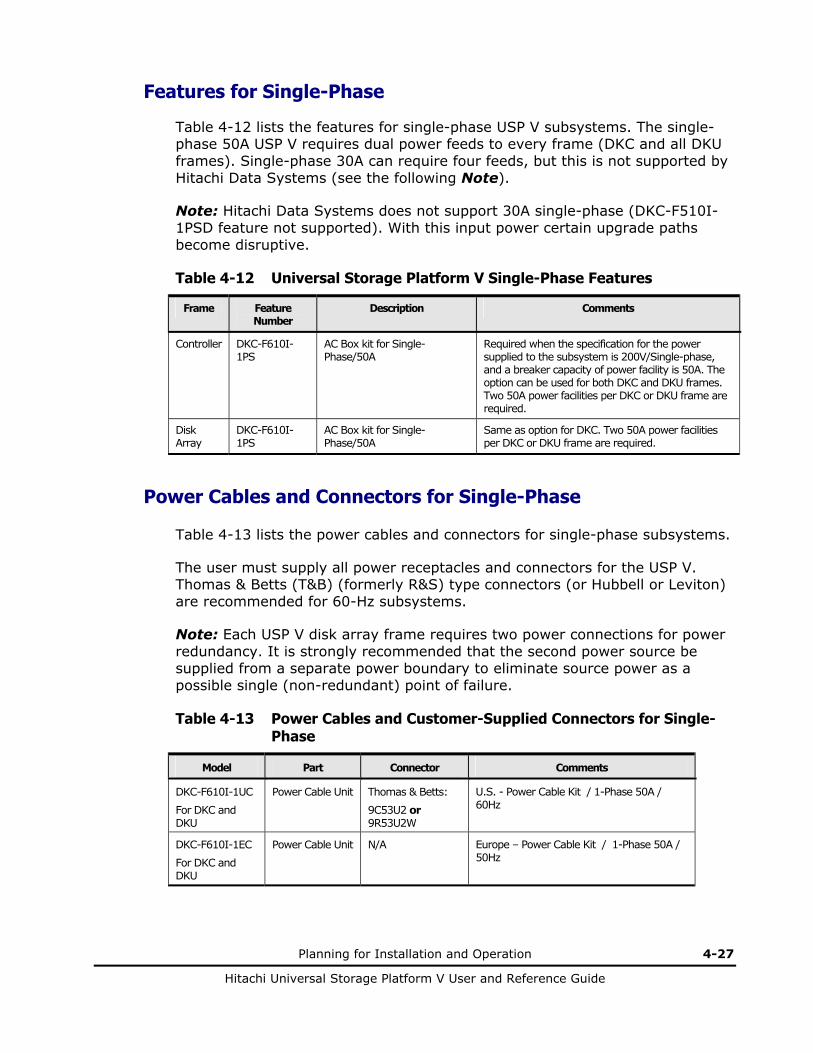
Planning for Installation and Operation 4-27
Hitachi Universal Storage Platform V User and Reference Guide
Features for Single-Phase
Table 4-12 lists the features for single-phase USP V subsystems. The single-phase 50A USP V requires dual power feeds to every frame (DKC and all DKU frames). Single-phase 30A can require four feeds, but this is not supported by Hitachi Data Systems (see the following Note).
Note: Hitachi Data Systems does not support 30A single-phase (DKC-F510I-1PSD feature not supported). With this input power certain upgrade paths become disruptive.
Table 4-12 Universal Storage Platform V Single-Phase Features
Frame Feature Number
Description Comments
Controller DKC-F610I-1PS
AC Box kit for Single-Phase/50A
Required when the specification for the power supplied to the subsystem is 200V/Single-phase, and a breaker capacity of power facility is 50A. The option can be used for both DKC and DKU frames. Two 50A power facilities per DKC or DKU frame are required.
Disk Array
DKC-F610I-1PS
AC Box kit for Single-Phase/50A
Same as option for DKC. Two 50A power facilities per DKC or DKU frame are required.
Power Cables and Connectors for Single-Phase
Table 4-13 lists the power cables and connectors for single-phase subsystems.
The user must supply all power receptacles and connectors for the USP V. Thomas & Betts (T&B) (formerly R&S) type connectors (or Hubbell or Leviton) are recommended for 60-Hz subsystems.
Note: Each USP V disk array frame requires two power connections for power redundancy. It is strongly recommended that the second power source be supplied from a separate power boundary to eliminate source power as a possible single (non-redundant) point of failure.
Table 4-13 Power Cables and Customer-Supplied Connectors for Single-Phase
Model Part Connector Comments
DKC-F610I-1UC
For DKC and DKU
Power Cable Unit Thomas & Betts:
9C53U2 or 9R53U2W
U.S. - Power Cable Kit / 1-Phase 50A / 60Hz
DKC-F610I-1EC
For DKC and DKU
Power Cable Unit N/A Europe – Power Cable Kit / 1-Phase 50A / 50Hz

4-28 Planning for Installation and Operation
Hitachi Universal Storage Platform V User and Reference Guide
*Note: For information on power connection specifications for locations outside the U.S., contact the Hitachi Data Systems Support Center for the specific country.
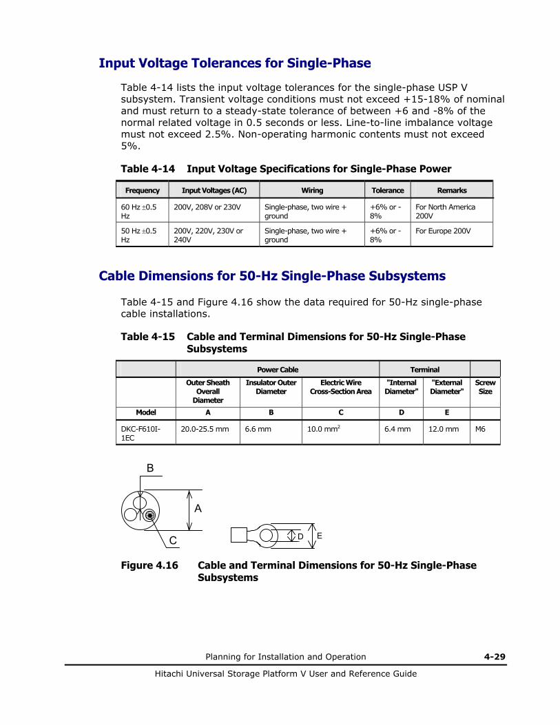
Planning for Installation and Operation 4-29
Hitachi Universal Storage Platform V User and Reference Guide
Input Voltage Tolerances for Single-Phase
Table 4-14 lists the input voltage tolerances for the single-phase USP V subsystem. Transient voltage conditions must not exceed +15-18% of nominal and must return to a steady-state tolerance of between +6 and -8% of the normal related voltage in 0.5 seconds or less. Line-to-line imbalance voltage must not exceed 2.5%. Non-operating harmonic contents must not exceed 5%.
Table 4-14 Input Voltage Specifications for Single-Phase Power
Frequency Input Voltages (AC) Wiring Tolerance Remarks
60 Hz ±0.5 Hz
200V, 208V or 230V Single-phase, two wire + ground
+6% or -8%
For North America 200V
50 Hz ±0.5 Hz
200V, 220V, 230V or 240V
Single-phase, two wire + ground
+6% or -8%
For Europe 200V
Cable Dimensions for 50-Hz Single-Phase Subsystems
Table 4-15 and Figure 4.16 show the data required for 50-Hz single-phase cable installations.
Table 4-15 Cable and Terminal Dimensions for 50-Hz Single-Phase Subsystems
Power Cable Terminal
Outer Sheath Overall
Diameter
Insulator OuterDiameter
Electric Wire Cross-Section Area
"Internal Diameter"
"External Diameter"
Screw Size
Model A B C D E
DKC-F610I-1EC
20.0-25.5 mm 6.6 mm 10.0 mm2 6.4 mm 12.0 mm M6
B
C
A
D E
Figure 4.16 Cable and Terminal Dimensions for 50-Hz Single-Phase Subsystems

4-30 Planning for Installation and Operation
Hitachi Universal Storage Platform V User and Reference Guide
Cable Requirements
Table 4-16 lists the cables required for the controller frame. These cables must be ordered separately, and the quantity depends on the type and number of channels and ports. ExSA (ESCON), FICON, and fibre-channel cables are available from Hitachi Data Systems.
Table 4-16 Cable Requirements
Cable Function/Description
PCI cable Connects Universal Storage Platform V to CPU power control interface.
FICON interface cables
Connects mainframe host systems, channel extenders, or FICON directors to USP V ports.
Single-mode cables:
Yellow in color with SC- and LC-type connectors.
8-10 micron. Most common is 9-micron single mode.
Multimode cables:
Orange cables with SC- and LC-type connectors.
50/125 micron and 62.5 micron multi-mode.
Note: The mainframe fibre adapters require an LC-type connector. When one of these adapters is connected to a host or switch device with an SC-type connector, you must have a cable which has an LC-type connector plug at one end and an SC-type connector plug at the other end.
ExSA (ESCON) interface cables
Connects mainframe host systems, channel extenders, or ESCON directors to USP V ports.
Multimode cables:
Commonly called jumper cables.
Use LED light source.
Plug directly on CHA cards.
Orange cables with MT-RJ connectors.*
Contain 2 fibers (transmit and receive).
62.5 micron (up to 3 km per link).
50 micron (up to 2 km per link).
Mono/Single mode cables:
Required on XDF links between ESCDs or IBM 9036 ESCON remote control extenders.
Use laser light source.
Yellow in color with MT-RJ connectors.*
8-10 micron. Most common is 9 micron.
*MT-RJ: An MT-RJ connector miniaturizes an ESCON connector. When a host side is an ESCON connector, a cable connectable with an MT-RJ connector is chosen, or a conversion kit is required.
Fibre cables Connects open-system host to Universal Storage Platform V fibre-channel or NAS ports. Fibre cable types are 50 / 125 micron or 62.5 / 125 micron multimode.
LC-type (little) connector is required for the 4-Gbps and 2-Gbps ports. Note: When a 4- or 2-Gbps port is connected to a host or switch device with an SC-type connector, you must have a cable which has an LC-type connector plug at one end and an SC-type connector plug at the other end.
Phone cable with RJ11 connector
Connects phone line to Universal Storage Platform V SVP for Hi-Track.
10/100 BaseT (Cat 5) cable with RJ45 connector
Connects Storage Navigator PC to Universal Storage Platform V. Can also be used for connecting multiple USP V subsystems together (daisy-chain).
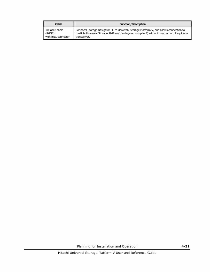
Planning for Installation and Operation 4-31
Hitachi Universal Storage Platform V User and Reference Guide
Cable Function/Description
10Base2 cable (RG58) with BNC connector
Connects Storage Navigator PC to Universal Storage Platform V, and allows connection to multiple Universal Storage Platform V subsystems (up to 8) without using a hub. Requires a transceiver.
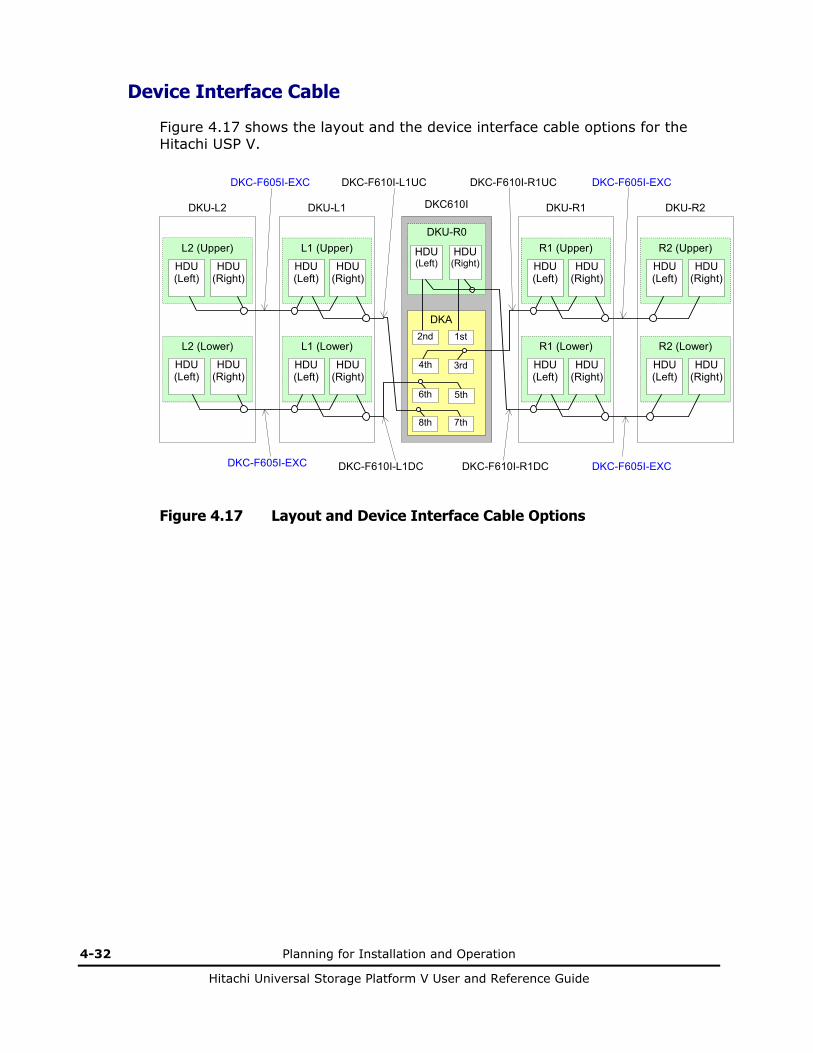
4-32 Planning for Installation and Operation
Hitachi Universal Storage Platform V User and Reference Guide
Device Interface Cable
Figure 4.17 shows the layout and the device interface cable options for the Hitachi USP V.
DKU-R0
HDU(Left)
HDU(Right)
DKC-F610I-L1UCDKC-F605I-EXC
DKC610I DKU-L2
DKA
L1 (Upper)
HDU(Right)
HDU (Left)
L1 (Lower)
HDU(Right)
HDU (Left)
L2 (Upper)
HDU (Right)
HDU (Left)
L2 (Lower)
HDU (Right)
HDU (Left)
R1 (Upper)
HDU (Right)
HDU(Left)
R1 (Lower)
HDU (Right)
HDU(Left)
R2 (Upper)
HDU(Right)
HDU(Left)
R2 (Lower)
HDU(Right)
HDU(Left)
DKU-L1 DKU-R1 DKU-R2
DKC-F610I-L1DCDKC-F605I-EXC
DKC-F610I-R1UC
DKC-F610I-R1DC
DKC-F605I-EXC
DKC-F605I-EXC
2nd 1st
4th 3rd
5th6th
8th 7th
Figure 4.17 Layout and Device Interface Cable Options
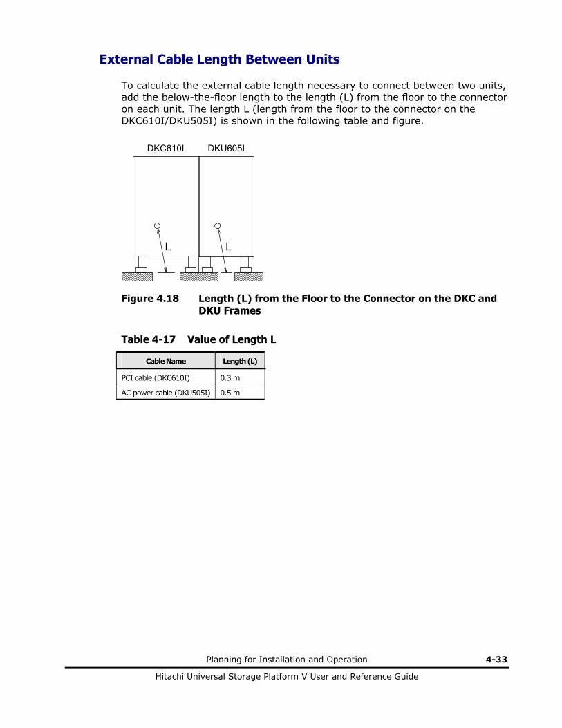
Planning for Installation and Operation 4-33
Hitachi Universal Storage Platform V User and Reference Guide
External Cable Length Between Units
To calculate the external cable length necessary to connect between two units, add the below-the-floor length to the length (L) from the floor to the connector on each unit. The length L (length from the floor to the connector on the DKC610I/DKU505I) is shown in the following table and figure.
L
DKC610I
L
DKU605I
Figure 4.18 Length (L) from the Floor to the Connector on the DKC and DKU Frames
Table 4-17 Value of Length L
Cable Name Length (L)
PCI cable (DKC610I) 0.3 m
AC power cable (DKU505I) 0.5 m
4-34 Planning for Installation and Operation
Hitachi Universal Storage Platform V User and Reference Guide
Channel Specifications and Requirements
Table 4-18 lists the specifications for each USP V mainframe channel option. Table 4-19 lists the specifications for each USP V open-systems channel option. Each channel adapter (CHA) feature consists of a pair of cards.
Note: Additional power supply is needed for the following configurations:
• When the total number of installed CHA and DKA options is four or more.
• When 68 GB or more of cache memory is to be installed.
• When 65 or more HDD canisters are to be installed.
Database Validator: All fibre-channel options for the USP V are equipped with the Database Validator function. When data for an Oracle database is written from the host to the array, the array checks the integrity of the data. If an error is detected with this function, the array does not write the erroneous data to the data volume in order to keep data integrity of the database.
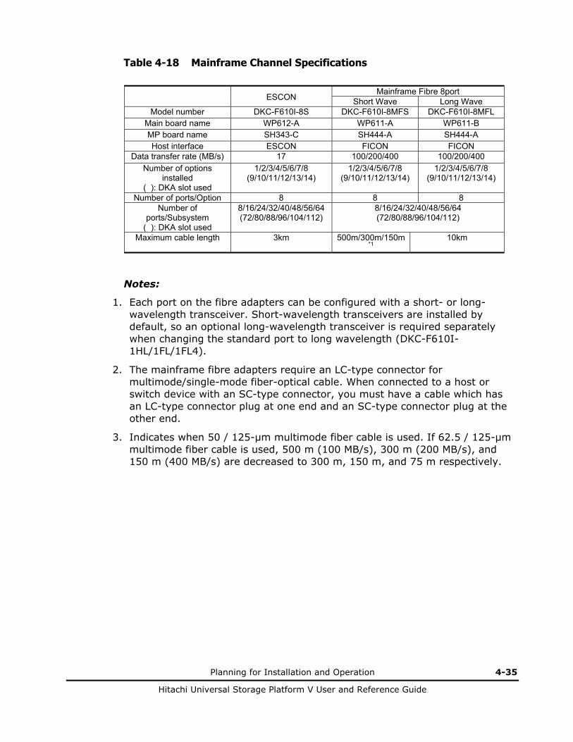
Planning for Installation and Operation 4-35
Hitachi Universal Storage Platform V User and Reference Guide
Table 4-18 Mainframe Channel Specifications
Mainframe Fibre 8port ESCON Short Wave Long Wave
Model number DKC-F610I-8S DKC-F610I-8MFS DKC-F610I-8MFL Main board name WP612-A WP611-A WP611-B MP board name SH343-C SH444-A SH444-A Host interface ESCON FICON FICON
Data transfer rate (MB/s) 17 100/200/400 100/200/400 Number of options
installed ( ): DKA slot used
1/2/3/4/5/6/7/8 (9/10/11/12/13/14)
1/2/3/4/5/6/7/8 (9/10/11/12/13/14)
1/2/3/4/5/6/7/8 (9/10/11/12/13/14)
Number of ports/Option 8 8 8 Number of
ports/Subsystem ( ): DKA slot used
8/16/24/32/40/48/56/64 (72/80/88/96/104/112)
8/16/24/32/40/48/56/64 (72/80/88/96/104/112)
Maximum cable length 3km 500m/300m/150m*1
10km
Notes:
1. Each port on the fibre adapters can be configured with a short- or long-wavelength transceiver. Short-wavelength transceivers are installed by default, so an optional long-wavelength transceiver is required separately when changing the standard port to long wavelength (DKC-F610I-1HL/1FL/1FL4).
2. The mainframe fibre adapters require an LC-type connector for multimode/single-mode fiber-optical cable. When connected to a host or switch device with an SC-type connector, you must have a cable which has an LC-type connector plug at one end and an SC-type connector plug at the other end.
3. Indicates when 50 / 125-µm multimode fiber cable is used. If 62.5 / 125-µm multimode fiber cable is used, 500 m (100 MB/s), 300 m (200 MB/s), and 150 m (400 MB/s) are decreased to 300 m, 150 m, and 75 m respectively.

4-36 Planning for Installation and Operation
Hitachi Universal Storage Platform V User and Reference Guide
Table 4-19 Open-Systems Channel Specifications
Fibre iSCSI*3 8port 16port 8port
Model number DKC-F610I-8FS*4 DKC-F610I-16FS*4 DKC-F610I-8IS Main board name WP610-B WP610-A WP613-A MP board name SH444-A SH444-A SH444-A Host interface FCP FCP Gigabit Ethernet
Data transfer rate (MB/s) 100/200/400 100/200/400 100 Number of options
installed ( ): DKA slot used
1/2/3/4/5/6/7/8 (9/10/11/12/13/14)
1/2/3/4/5/6/7/8 (9/10/11/12/13/14)
1/2/3/4/5/6/7/8 (9/10/11/12/13/14)
Number of ports / Option 8 16 8 Number of
ports/Subsystem ( ): DKA slot used
8/16/24/32/40/48/56/64
(72/80/88/96/104/112)
16/32/48/64/80/96/112/128 (144/160/176/192/208/224)
8/16/24/32/40/48/56/64
(72/80/88/96/104/112) Short Wave 500m/300m/150m *1 500m/300m/150m *1 500m/275m *2 Maximum
cable length
Long Wave 10km 10km -
Notes:
1. Each port on the fibre adapters can be configured with a short- or long-wavelength transceiver. Short-wavelength transceivers are installed by default, so an optional long-wavelength transceiver is required separately when changing the standard port to long wavelength (DKC-F510I-1HL/1FL/1FL4).
2. The fibre-channel adapters require an LC-type connector for multimode/single-mode fiber-optical cable. When an FC adapter is connected to a host or switch device with an SC-type connector, you must have a cable which has an LC-type connector plug at one end and an SC-type connector plug at the other end.
3. The maximum number of NAS CHAs that can be installed is 4.
4. Indicates when 50 / 125-µm multimode fiber cable is used. If 62.5 / 125-µm multimode fiber cable is used, 500 m (100 MB/s), 300 m (200 MB/s), and 150 m (400 MB/s) are decreased to 300 m, 150 m, and 75 m respectively.
5. Indicates when 50/125 µm multi-mode fiber cable is used. If 62.5/125 µm multi-mode fiber cable is used, maximum length is decreased to 275 m.

Planning for Installation and Operation 4-37
Hitachi Universal Storage Platform V User and Reference Guide
Environmental Specifications and Requirements
The environmental specifications and requirements for the USP V include:
• Temperature, humidity, and altitude requirements
• Power consumption and heat output specifications
• Loudness
• Air flow requirements
• Vibration and shock tolerances
Temperature, Humidity, and Altitude Requirements
Table 4-20 lists the temperature, humidity, and altitude requirements for the USP V. The recommended operational room temperature is 70–75°F (21–24°C). The recommended operational relative humidity is 50% to 55%.
Table 4-20 Temperature, Humidity, and Altitude Requirements
Operating *1 Non-Operating *2 Shipping & Storage *3
Parameter Low High Low High Low High
Temperature °F (°C) 60 (16) 90 (32) 14 (-10)
109 (43) 5 (-25) 140 (60)
Relative Humidity (%) *4 20 - 80 8 – 90 5 – 95
Max. Wet Bulb °F (°C) 79 (26) 81 (27) 84 (29)
Temperature Deviation °F (°C) / hour
18 (10) 18 (10) 36 (20)
Altitude -60 m to 3,000 m —
Notes:
1. Environmental specification for operating condition should be satisfied before the disk subsystem is powered on. The maximum temperature of 90°F (32°C) should be strictly satisfied at the air inlet portion of the subsystem. The recommended temperature range is 70-75°F (21-24°C).
2. Non-operating condition includes both packing and unpacking conditions unless otherwise specified.
3. During shipping or storage, the product should be packed with factory packing.
4. No condensation in or around the drive should be observed under any conditions.

4-38 Planning for Installation and Operation
Hitachi Universal Storage Platform V User and Reference Guide
Power Consumption and Heat Output Specifications
Table 4-21 lists the power consumption and heat output parameters for the USP V DKC components. Table 4-22 lists the power consumption and heat output parameters for the USP V DKU components. These data generally apply to both 60-Hz and 50-Hz subsystems.
Note: The air flow requirements for the USP V are greater than those for the Lightning 9900V subsystem.
Table 4-21 DKC Component Specs: Heat Output, Power Consumption, Air Flow
No. Model Number
Heat
Output
(kW)
Power
Consumption
(kVA)
Air Flow
(m3/min.)
1 DKC610I-5 0.834 0.860 34
2 DKC-F610I-DH — — —
3 DKC-F610I-DS — — —
4 DKC-F610I-3PS — — —
5 DKC-F610I-3EC — — —
6 DKC-F610I-3UC — — —
7 DKC-F610I-1PS — — —
8 DKC-F610I-1EC — — —
9 DKC-F610I-1UC — — —
10 DKC-F610I-1PSD — — —
11 DKC-F610I-1ECD — — —
12 DKC-F610I-1UCD — — —
13 DKC-F610I-APC — — —
14 DKC-F610I-AB 0.029 0.030 —
15 DKC-F610I-ABX 0.128 0.132 —
16 DKC-F610I-CX 0.005 0.005 —
17 DKC-F610I-C4G 0.015 0.015 —
18 DKC-F610I-C8G 0.019 0.020 —
19 DKC-F610I-SX 0.005 0.005 —
20 DKC-F610I-S2GQ 0.013 0.013 —
21 DKC-F610I-S4GQ 0.013 0.013 —
22 DKC-F610I-CSW 0.029 0.03 —
23 DKC-F610I-DKA 0.097 0.100 —
24 DKC-F610I-SVP 0.073 0.075 —
25 DKC-F610I-PCI 0.002 0.002 —
26 DKC-F610I-R1DC — — —

Planning for Installation and Operation 4-39
Hitachi Universal Storage Platform V User and Reference Guide
27 DKC-F610I-R1UC — — —
28 DKC-F610I-L1DC — — —
29 DKC-F610I-L1UC — — —
30 DKC-F610I-MDM 0.006 0.006 —
31 DKC-F610I-8S 0.146 0.150 —
32 DKC-F610I-8MFS 0.146 0.150 —
33 DKC-F610I-8MFL 0.146 0.150 —
34 DKC-F610I-8FS 0.130 0.135 —
35 DKC-F610I-16FS 0.146 0.150 —
36 DKC-F610I-8IS 0.108 0.113 —
37 DKC-F610I-1FL — — —
38 DKC-F610I-1FS — — —
No Model number
Heat
Output
(kW)
Power
Consumption
(kVA)
Air Flow
(m3/min.)
1 DKU-F605I-18 0.601 0.62 32
2 DKU-F605I-DH — — —
3 DKU-F605I-DS — — —
4 DKU-F605I-AKT 0.291 0.3 —
5 DKU-F605I-EXC — — —
6 DKU-F605I-72KS 0.020 0.021 —
7 DKU-F605I-146KS 0.020 0.021 —
8 DKU-F605I-300JS 0.020 0.021 —
Table 4-22 DKU Component Specs: Heat Output, Power Consumption, Air Flow
Model Number Heat Output (kW)
Power Consumption (kVA) Air Flow (m3/min.)
DKU-605I-18 0.659 0.686 31
DKU-F605I-DH — — —
DKU-F605I-DS (Sun door kit)
— — —
DKU-F605I-FSWA 0.264 0.275 —
DKU-F605I-EXC — — —
DKU-F605I-72KS 0.022 0.024 —
DKU-F605I-146JS 0.023 0.025 —
DKU-F605I-146KS 0.023 0.025 —
DKU-F605I-300JS 0.023 0.025 —
4-40 Planning for Installation and Operation
Hitachi Universal Storage Platform V User and Reference Guide
Notes:
1. These options can be used for both the DKC610I and DKU605I.
2. This is common to the option installed in DKC460I (Lightning 9900V). For use on DKC510I (USP V), bundle the extra cable.

Planning for Installation and Operation 4-41
Hitachi Universal Storage Platform V User and Reference Guide
Loudness
The acoustic emission values [loudness in dB(A)] for a maximum USP V configuration (one DKC, four DKUs) are:
Front/rear = 65 dB(A) Both sides = 65 dB(A)
Note: These values were extrapolated from the values for one DKC and one DKU.
Important: Measurement point: 1 m above floor and 1 m from surface of the product.
Air Flow Requirements
The USP V is air cooled. Air must enter the subsystem through the air flow intakes at the sides and bottoms of the frames and must be exhausted out of the top, so it is very important that the air intakes and outlets remain clear. Hitachi Data Systems recommends that under-floor air cooling has a positive pressure and meets the specifications listed in Table 4-23.
For subsystems located at elevations from 3000 to 7000 feet (900 to 2100 meters) above sea level, decrease the maximum air temperature by two degrees for each 1000 feet (300 meters) above 3000 feet (900 meters).
Note: The air flow requirements for the USP V are greater than those for the Lightning 9900V subsystem.
Table 4-23 Internal Air Flow
Subsystem Configuration Air Flow (m3/min)
Air Flow (ft3/min)
Controller Frame (all configurations)
34 1553.84
Array Frame (all configurations) 32 1094.75
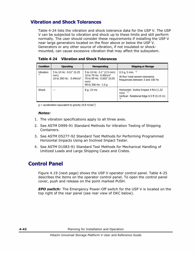
4-42 Planning for Installation and Operation
Hitachi Universal Storage Platform V User and Reference Guide
Vibration and Shock Tolerances
Table 4-24 lists the vibration and shock tolerance data for the USP V. The USP V can be subjected to vibration and shock up to these limits and still perform normally. The user should consider these requirements if installing the USP V near large generators located on the floor above or below the USP V. Generators or any other source of vibration, if not insulated or shock-mounted, can cause excessive vibration that may affect the subsystem.
Table 4-24 Vibration and Shock Tolerances
Condition Operating Nonoperating Shipping or Storage
Vibration *1
5 to 10 Hz: 0.01" (0.25 mm) 10 to 300 Hz: 0.49m/s2
5 to 10 Hz: 0.1" (2.5 mm) 10 to 70 Hz: 0.49m/s2 70 to 99 Hz: 0.002" (0.05 mm) 99 to 300 Hz: 1.0 g
0.5 g, 5 min. *2
At four most severe resonance frequencies between 3 and 100 Hz
Shock —- 8 g, 15 ms Horizontal: Incline Impact 4 ft/s (1.22 m/s) *3 Vertical: Rotational Edge 0.5 ft (0.15 m) *4
g = acceleration equivalent to gravity (9.8 m/sec2)
Notes:
1. The vibration specifications apply to all three axes.
2. See ASTM D999-91 Standard Methods for Vibration Testing of Shipping Containers.
3. See ASTM D5277-92 Standard Test Methods for Performing Programmed Horizontal Impacts Using an Inclined Impact Tester.
4. See ASTM D1083-91 Standard Test Methods for Mechanical Handling of Unitized Loads and Large Shipping Cases and Crates.
Control Panel
Figure 4.19 (next page) shows the USP V operator control panel. Table 4-25 describes the items on the operator control panel. To open the control panel cover, push and release on the point marked PUSH.
EPO switch: The Emergency Power-Off switch for the USP V is located on the top right of the rear panel (see rear view of DKC below).

Planning for Installation and Operation 4-43
Hitachi Universal Storage Platform V User and Reference Guide
FRONT VIEW (Unit: mm)
1,920
Operator Panel
READY
ALARM
MESSAGE
RESTART REMOTE MAINTENANCE PROCESSING
ENABLE
DISABLE
BS-ON
PS-ON
ENABLE PS ON
OFF
EMERGENCY
SUB-SYSTEM
TOP VIEW
75016 16
925
REAR VIEW
EMERGENCY
UNIT EMERGENCYPOWER OFF
Figure 4.19 Universal Storage Platform V Control Panel
Note: This illustration does not show the service port under the EPO switch.
Table 4-25 Universal Storage Platform V Control Panel
Name Type Description
SUBSYSTEM READY LED (Green)
When lit, indicates that input/output operation on the channel interface is possible. Applies to both storage clusters.

4-44 Planning for Installation and Operation
Hitachi Universal Storage Platform V User and Reference Guide
SUBSYSTEM ALARM LED (Red)
When lit, indicates that low DC voltage, high DC current, abnormally high temperature, or a failure has occurred. Applies to both storage clusters.
SUBSYSTEM MESSAGE
LED (Amber)
On: Indicates that a SIM (Message) was generated from either of the clusters. Applied to both storage clusters.
Blinking: Indicates that the SVP failure has occurred.
SUBSYSTEM RESTART
Switch Used to un-fence a fenced drive path and to release the Write Inhibit command. Applies to both storage clusters.
REMOTE MAINTENANCE PROCESSING
LED (Amber)
When lit, indicates that remote maintenance activity is in process. If remote maintenance is not in use, this LED is not lit. Applies to both storage clusters.
REMOTE MAINTENANCE ENABLE/DISABLE
Switch Used for remote maintenance. While executing remote maintenance (the REMOTE MAINTENANCE PROCESSING LED in item 5 is blinking), when switching from ENABLE to DISABLE, remote maintenance is interrupted. If the remote maintenance function is not used, this switch is ineffective. Applies to both storage clusters.
BS-ON LED (Amber)
Indicates input power is available.
PS-ON LED (Green)
Indicates that subsystem is powered on. Applies to both storage clusters.
PS SW ENABLE Switch Used to enable the PS ON/ PS OFF switch. To be enabling the PS ON/ PS OFF switch, turn the PS SW ENABLE switch to the ENABLE position.
PS ON / PS OFF Switch Used to power subsystem on/off. This switch is valid when the PS REMOTE/LOCAL switch is set to LOCAL. Applies to both storage clusters.
EMERGENCY LED (Red)
This LED shows status of EPO switch on the rear door. OFF: Indicates that the EPO switch is off. ON: Indicates that the EPO switch is on.
EMERGENCY POWER OFF (EPO)
1-Way Locking Switch
Used to shut down power to both storage clusters in an emergency.

Planning for Installation and Operation 4-45
Hitachi Universal Storage Platform V User and Reference Guide
Emergency Power-Off (EPO)
The disk subsystem EMERGENCY POWER OFF (EPO) switch is located in the rear of the DKC (see Figure 4.19). Use this switch only in case of an emergency.
To power off the disk subsystem in case of an emergency:
1. Go to the rear of the DKC, and pull the emergency power-off switch (item 13 in Figure 4.19) up and then out towards you as illustrated on the switch.
2. Call the technical support center. The EPO switch must be reset by service personnel before the disk subsystem can be powered on again.
Open-Systems Operations
Command Tag Queuing
The USP V supports command tag queuing for open-system devices. Command tag queuing enables hosts to issue multiple disk commands to the fibre-channel adapter without having to serialize the operations. Instead of processing and acknowledging each disk I/O sequentially as presented by the applications, the USP V processes requests in the most efficient order to minimize head seek operations and disk rotational delay.
Note: The queue depth parameter may need to be adjusted for the USP V devices. Please refer to the appropriate USP V configuration guide for queue depth requirements and instructions on changing queue depth and other related system and device parameters (refer to Table 3-2 for a list of the open-system configuration guides for the USP V.
Host/Application Failover Support
The USP V supports many industry-standard products which provide host and/or application failover capabilities (for example, Hitachi Dynamic Link Manager, VERITAS Cluster Server, Sun Cluster, VERITAS Volume Manager/DMP, HP MC/ServiceGuard, HACMP, Microsoft Cluster Server). For the latest information on failover and LVM product releases, availability, and compatibility, please contact your Hitachi Data Systems account team.
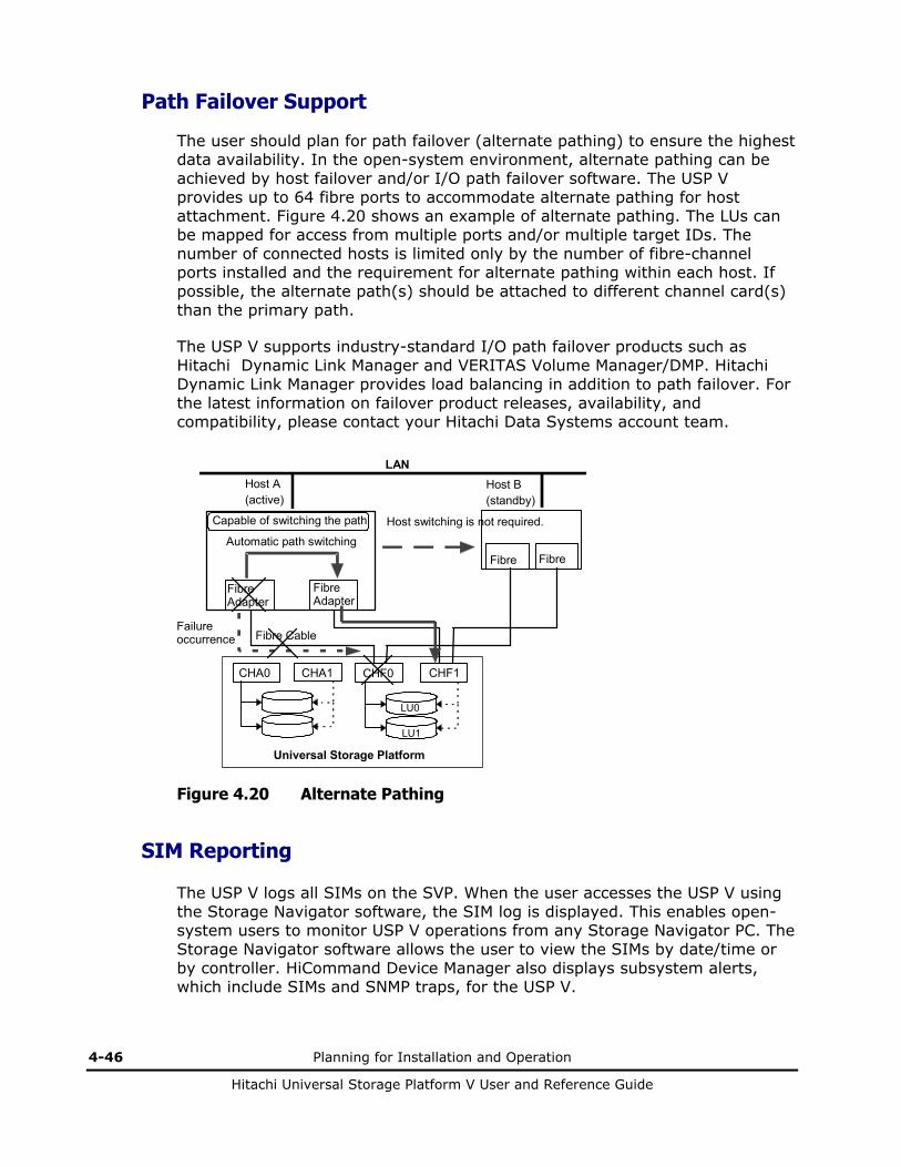
4-46 Planning for Installation and Operation
Hitachi Universal Storage Platform V User and Reference Guide
Path Failover Support
The user should plan for path failover (alternate pathing) to ensure the highest data availability. In the open-system environment, alternate pathing can be achieved by host failover and/or I/O path failover software. The USP V provides up to 64 fibre ports to accommodate alternate pathing for host attachment. Figure 4.20 shows an example of alternate pathing. The LUs can be mapped for access from multiple ports and/or multiple target IDs. The number of connected hosts is limited only by the number of fibre-channel ports installed and the requirement for alternate pathing within each host. If possible, the alternate path(s) should be attached to different channel card(s) than the primary path.
The USP V supports industry-standard I/O path failover products such as Hitachi Dynamic Link Manager and VERITAS Volume Manager/DMP. Hitachi Dynamic Link Manager provides load balancing in addition to path failover. For the latest information on failover product releases, availability, and compatibility, please contact your Hitachi Data Systems account team.
Fibre Adapter
LU0
LU1
CHF0 CHF1CHA0 CHA1
Failure occurrence
Automatic path switching
Host switching is not required.Capable of switching the path
LANHost A (active)
Fibre Adapter
Host B(standby)
FibreFibre
Universal Storage Platform
Fibre Cable
Figure 4.20 Alternate Pathing
SIM Reporting
The USP V logs all SIMs on the SVP. When the user accesses the USP V using the Storage Navigator software, the SIM log is displayed. This enables open-system users to monitor USP V operations from any Storage Navigator PC. The Storage Navigator software allows the user to view the SIMs by date/time or by controller. HiCommand Device Manager also displays subsystem alerts, which include SIMs and SNMP traps, for the USP V.

Planning for Installation and Operation 4-47
Hitachi Universal Storage Platform V User and Reference Guide
SNMP Remote Subsystem Management
The USP V supports the industry-standard simple network management protocol (SNMP) for remote subsystem management from the UNIX/PC server host. SNMP is used to transport management information between the USP V and the SNMP manager on the host. The SNMP agent on the USP V sends status information to the host(s) when requested by a host or when a significant event occurs. Notification of error conditions is made in real time, providing UNIX/PC server users with the same level of monitoring and support available to mainframe users. The SIM reporting over SNMP enables users to monitor the USP V without having to check the Storage Navigator for SIMs. HiCommand Device Manager also displays subsystem alerts, which include SIMs and SNMP traps, for the USP V.
Note: For further information on SNMP, please see the Hitachi Universal Storage Platform V V (USP V) SNMP API User and Reference Guide (MK-94RD213), or contact your Hitachi Data Systems account team.

4-48 Planning for Installation and Operation
Hitachi Universal Storage Platform V User and Reference Guide

5
Troubleshooting 5-1
Hitachi Universal Storage Platform V User and Reference Guide
Troubleshooting
This chapter provides troubleshooting guidelines and customer support contact information.
Troubleshooting
Calling the Hitachi Data Systems Support Center
Service Information Messages (SIMs)
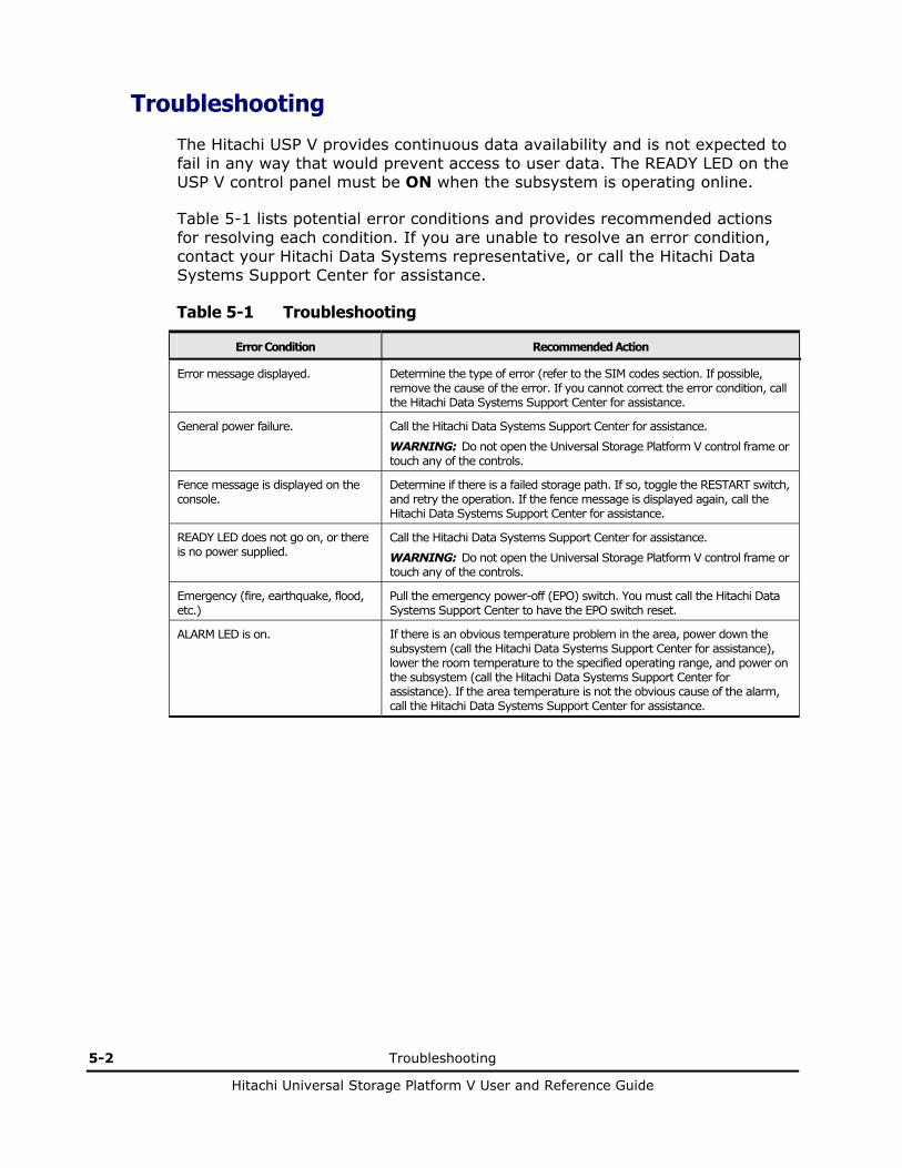
5-2 Troubleshooting
Hitachi Universal Storage Platform V User and Reference Guide
Troubleshooting
The Hitachi USP V provides continuous data availability and is not expected to fail in any way that would prevent access to user data. The READY LED on the USP V control panel must be ON when the subsystem is operating online.
Table 5-1 lists potential error conditions and provides recommended actions for resolving each condition. If you are unable to resolve an error condition, contact your Hitachi Data Systems representative, or call the Hitachi Data Systems Support Center for assistance.
Table 5-1 Troubleshooting
Error Condition Recommended Action
Error message displayed. Determine the type of error (refer to the SIM codes section. If possible, remove the cause of the error. If you cannot correct the error condition, call the Hitachi Data Systems Support Center for assistance.
General power failure. Call the Hitachi Data Systems Support Center for assistance.
WARNING: Do not open the Universal Storage Platform V control frame or touch any of the controls.
Fence message is displayed on the console.
Determine if there is a failed storage path. If so, toggle the RESTART switch, and retry the operation. If the fence message is displayed again, call the Hitachi Data Systems Support Center for assistance.
READY LED does not go on, or there is no power supplied.
Call the Hitachi Data Systems Support Center for assistance.
WARNING: Do not open the Universal Storage Platform V control frame or touch any of the controls.
Emergency (fire, earthquake, flood, etc.)
Pull the emergency power-off (EPO) switch. You must call the Hitachi Data Systems Support Center to have the EPO switch reset.
ALARM LED is on. If there is an obvious temperature problem in the area, power down the subsystem (call the Hitachi Data Systems Support Center for assistance), lower the room temperature to the specified operating range, and power on the subsystem (call the Hitachi Data Systems Support Center for assistance). If the area temperature is not the obvious cause of the alarm, call the Hitachi Data Systems Support Center for assistance.
Troubleshooting 5-3
Hitachi Universal Storage Platform V User and Reference Guide
Calling the Hitachi Data Systems Support Center
If you need to call the Hitachi Data Systems Support Center, make sure to provide as much information about the problem as possible, including:
• The Storage Navigator trace files saved on diskette using the FD Dump tool (see the Hitachi Universal Storage Platform V (USP V) Storage Navigator User’s Guide)
• The configuration definition files (spreadsheets) downloaded (exported) using the Configuration File Loader function (see the Hitachi Universal Storage Platform V (USP V) Storage Navigator User’s Guide)
• The circumstances surrounding the error or failure
• The exact content of any error messages displayed on the host system(s)
• The error code(s) displayed on the Storage Navigator
• The service information messages (SIMs) displayed on the Storage Navigator and the reference codes and severity levels of the recent SIMs
• The worldwide Hitachi Data Systems Support Centers are:
• Hitachi Data Systems North America/Latin America San Diego, California, USA 1-800-446-0744
• Hitachi Data Systems Europe Buckinghamshire, United Kingdom 011-44-175-361-8000
• Hitachi Data Systems Asia Pacific North Ryde, Australia 61-2-9325-3300

5-4 Troubleshooting
Hitachi Universal Storage Platform V User and Reference Guide
Service Information Messages (SIMs)
The USP V generates service information messages (SIMs) to identify normal operations (for example, TrueCopy pair status change) as well as service requirements and errors or failures. Note: For assistance with SIMs, please call the Hitachi Data Systems Support Center.
SIMs can be generated by the front-end and back-end directors and by the SVP. All SIMs generated by the USP V are stored on the SVP for use by Hitachi Data Systems personnel, logged in the SYS1.LOGREC dataset of the mainframe host system, displayed by the Storage Navigator software, and reported over SNMP to the open-system host. The SIM display on USP V Storage Navigator enables users to remotely view the SIMs reported by the attached USP Vs. Each time a SIM is generated, the amber Message LED on the USP V control panel turns on. The Hi-Track remote maintenance tool also reports all SIMs to the Hitachi Data Systems Support Center.
SIMs are classified according to severity: service, moderate, serious, or acute. The service and moderate SIMs (lowest severity) do not require immediate attention and are addressed during routine maintenance. The serious and acute SIMs (highest severity) are reported to the mainframe host(s) once every eight hours. Note: If a serious or acute-level SIM is reported, the user should call the Hitachi Data Systems Support Center immediately to ensure that the problem is being addressed.
Figure 5.1 illustrates a typical 32-byte SIM from the USP V. SIMs are displayed by reference code (RC) and severity. The six-digit RC, which is composed of bytes 22, 23, and 13, identifies the possible error and determines the severity. The SIM type, located in byte 28, indicates which component experienced the error.
Byte
SIM SSB
0 1 2 3 4 5 6 8 9 107 11 12 13 14 15 16 17 18 19 20 21 22 23 2524 26 27 28 29 30 31
0090 10 00 00 00E0 44 1000 0C 69 00000000 02 05 10 42 C000 020004 0400 80 30 70 F1F8
SSB22, 23SSB13
Indicates SIM. RC = 307080
SIM type F1: DKC SIM F2: CACHE SIM FE: DEVICE SIM FF: MEDIA SIM
Figure 5.1 Typical SIM Showing Reference Code and SIM Type

A
Units and Unit Conversions A-1
Hitachi Universal Storage Platform V User and Reference Guide
Units and Unit Conversions
This appendix describes the Storage capacities for LDEVs on the USP V are calculated based on the following values: 1 KB = 1,024 bytes, 1 MB = 1,0242 bytes, 1 GB = 1,0243 bytes, 1 TB = 1,0244 bytes. Storage capacities for HDDs are calculated based on 1,000 (103) instead of 1,024 (210).
Table A.1 provides unit conversions for the standard (U.S.) and metric measurement systems.
Table A.1 Unit Conversions for Standard (U.S.) and Metric Measures
From Multiply By: To Get:
British thermal units (BTU) 0.251996 Kilocalories (kcal)
British thermal units (BTU) 0.000293018 Kilowatts (kW)
Inches (in) 2.54000508 Centimeters (cm)
Feet (ft) 0.3048006096 Meters (m)
Square feet (ft2) 0.09290341 Square meters (m2)
Cubic feet per minute (ft3/min) 0.028317016 Cubic meters per minute (m3/min)
Pound (lb) 0.4535924277 Kilogram (kg)
Kilocalories (kcal) 3.96832 British thermal units (BTU)
Kilocalories (kcal) 1.16279 × 10⁻³ Kilowatts (kW)
Kilowatts (kW) 3412.08 British thermal units (BTU)
Kilowatts (kW) 859.828 Kilocalories (kcal)
Millimeters (mm) 0.03937 Inches (in)
Centimeters (cm) 0.3937 Inches (in)
Meters (m) 39.369996 Inches (in)
Meters (m) 3.280833 Feet (ft)
Square meters (m2) 10.76387 Square feet (ft2)
Cubic meters per minute (m3/min) 35.314445 Cubic feet per minute (ft3/min)
Kilograms (kg) 2.2046 Pounds (lb)
Ton (refrigerated) 12,000 BTUs per hour (BTU/hr)

A-2 Units and Unit Conversions
Hitachi Universal Storage Platform V User and Reference Guide
Degrees Fahrenheit (°F) subtract 32, then multiply result by 0.555556
Degrees centigrade (°C) °C = (°F - 32) × 0.555556
Degrees centigrade (°C) multiply by 1.8, then add 32 to result
Degrees Fahrenheit (°F) °F = (°C × 1.8) + 32
Degrees Fahrenheit per hour (°F/hour) 0.555555 Degrees centigrade per hour (°C/hour)
Degrees centigrade per hour (°C/hour) 1.8 Degrees Fahrenheit per hour (°F/hour)

Acronyms and Abbreviations Acronyms-1
Hitachi Universal Storage Platform V User and Reference Guide
Acronyms and Abbreviations
A ampere ACP array control processor (another name for back-end director) ASTM American Society for Testing and Materials AVE average
BC business continuity BED back-end director BS basic (power) supply BSA bus adapter BTU British thermal unit
°C degrees centigrade/Celsius ca cache CC Concurrent Copy CCI Command Control Interface CD compact disk CEC Canadian Electroacoustic Community CFW cache fast write CH channel CHA channel adapter CHIP client-host interface processor (another name for front-end director) CHL channel CHN NAS channel adapter CHP channel processor or channel path CHPID channel path identifier CIFS common internet file system CKD count key data CL cluster CLI command line interface CLPR cache logical partition CPU central processing unit CSA Canadian Standards Association CSW cache switch CU control unit CVS custom volume size
DASD direct access storage device dB(A) decibel (A-weighted)

Acronyms-2 Acronyms and Abbreviations
Hitachi Universal Storage Platform V User and Reference Guide
DFDSS Data Facility Dataset Services DFSMS Data Facility System Managed Storage DFW DASD fast write DKA disk adapter DKC disk controller, disk controller frame (DKC510I = Universal Storage
Platform V) DKU disk unit, disk array frame (DKU505I = Universal Storage Platform V) DLM data lifecycle management DNS domain name system dr drive DRAM dynamic random access memory DSF Device Support Facilities DTDS+ Disaster Tolerant Disk Subsystem Plus
ECKD Extended Count Key Data EOF end of field EMI electromagnetic interference EPO emergency power-off EREP Error Reporting ESA Enterprise Systems Architecture ESCON Enterprise System Connection (IBM trademark for optical channels) ESS Enterprise Storage Server® ExSA Extended Serial Adapter
FAL File Access Library (part of the Cross-OS File Exchange software) FBA fixed-block architecture FC fibre-channel FC-AL fibre-channel arbitrated loop FCC Federal Communications Commission FCP fibre-channel protocol FCU File Conversion Utility (part of the Cross-OS File Exchange software) FDR Fast Dump/Restore FED front-end director FICON Fiber Connection (IBM trademark for fiber connection technology) F/M format/message FWD fast wide differential FX Hitachi Cross-OS File Exchange
g acceleration of gravity (9.8 m/s2) (unit used for vibration and shock) Gb gigabit GB gigabyte (see “Convention for Storage Capacity Values” in the
Preface) Gbps, Gb/s
gigabit per second
GLM gigabyte link module GLPR global logical partition GUI graphical user interface
HACMP High Availability Cluster Multi-Processing HBA host bus adapter HCD hardware configuration definition HCPF Hitachi Concurrent Processing Facility HDLM Hitachi Dynamic Link Manager HDS Hitachi Data Systems

Acronyms and Abbreviations Acronyms-3
Hitachi Universal Storage Platform V User and Reference Guide
HDU hard disk unit Hi-Star Hierarchical Star Network HIXFS Hitachi NAS enhancement XFS HSN Hierarchical Star Network HWM high-water mark Hz Hertz
ICKDSF A DSF command used to perform media maintenance IDCAMS access method services (a component of Data Facility Product) IML initial microprogram load in. inch(es) IO, I/O input/output (operation or device) IOCP input/output configuration program
JCL job control language
KB kilobyte (see “Convention for Storage Capacity Values” in the Preface) kcal kilocalorie kg kilogram km kilometer kVA kilovolt-ampere kW kilowatt
LAN local area network lb pound LD logical device LDEV logical device LED light-emitting diode LPAR logical partition LCP link control processor, local control port LRU least recently used LU logical unit LUN logical unit number, logical unit LVI logical volume image LVM logical volume manager, Logical Volume Manager LW long wavelength
m meter MB megabyte (see “Convention for Storage Capacity Values” in the
Preface) MIH missing interrupt handler mm millimeter MP microprocessor MPLF Multi-Path Locking Facility MR magnetoresistive ms, msec millisecond MVS Multiple Virtual Storage (including MVS/ESA, MVS/XA)
NAS network-attached storage NBU NetBackup (a VERITAS software product) NEC National Electrical Code NFS network file system NIS network information service NTP network time protocol NVS nonvolatile storage

Acronyms-4 Acronyms and Abbreviations
Hitachi Universal Storage Platform V User and Reference Guide
ODM Object Data Manager OEM original equipment manufacturer OFC open fibre control ORM online read margin OS operating system
PAV Parallel Access Volume PC personal computer system PCI power control interface P/DAS PPRC/dynamic address switching (an IBM mainframe host software
function) PDL Product Documentation Library PPRC Peer-to-Peer Remote Copy (an IBM mainframe host software
function) PS power supply
RAB RAID Advisory Board RAID redundant array of independent disks RAM random-access memory RC reference code RISC reduced instruction-set computer R&S Russell & Stoll (replaced by Thomas & Betts, T&B) R/W read/write
S/390 IBM System/390 architecture SAN storage-area network SCSI small computer system interface SCP state-change pending sec. second seq. sequential SFP small form-factor pluggable SGI Silicon Graphics, Inc. SI ShadowImage SIM service information message SIz ShadowImage for z/OS SLPR storage logical partition SMS System Managed Storage SNMP simple network management protocol SSID storage subsystem identification SVP service processor SW switch, short wavelength
TB terabyte (see “Convention for Storage Capacity Values” in the Preface)
T&B Thomas & Betts TC TrueCopy TCz TrueCopy for z/OS TID target ID TPF Transaction Processing Facility TSO Time Sharing Option (an IBM mainframe operating system option)
UCB unit control block UIM unit information module UL Underwriters’ Laboratories

Acronyms and Abbreviations Acronyms-5
Hitachi Universal Storage Platform V User and Reference Guide
μm micron, micrometer USP V Hitachi Universal Storage Platform V V (USP V)
VA volt-ampere VAC volts AC VCS VERITAS Cluster Server VDE Verband Deutscher Elektrotechniker VDEV virtual device VM Virtual Machine (an IBM mainframe system control program) VOLID volume ID volser volume serial number VSE Virtual Storage Extension (an IBM mainframe operating system) VTOC volume table of contents
W watt WLM Workload Manager (an IBM mainframe host software function)
XA System/370 Extended Architecture XDF Extended Distance Feature (for ExSA channels) XRC Extended Remote Copy (an IBM mainframe host software function)

Acronyms-6 Acronyms and Abbreviations
Hitachi Universal Storage Platform V User and Reference Guide
Index Index-1
Hitachi Universal Storage Platform V User and Reference Guide
Index


Hitachi Universal Storage Platform V User and Reference Guide
A AC power plugs, 26 activity bottlenecks, 68 air intakes, 113 algorithms
cache control, 39 cache mgmt, 32 least recently used, 39 sequential prefetch, 39
alternate pathing fibre port qty, 118 scheme, 18
arbitrated-loop topology, 24 array
domain, 24 group, 28
asynchronous remote copy, 57 xrc remote copy, 60
B back-end director, 24 balance I/O workloads, 63 battery backup, 13 bus adapters, 5
C cable installations
three-phase, 95 cache
duplex segments, 13 global, 54 memory battery backup, 19 nonvolatile, 12 storing data, 63 switch cards, 20
canister mount, 28 CCI scripting, 59 channel adapter
boards, 21 pairs, 12
commands cache fast write, 19 cgroup, 43 multiple disk, 117 scsi, 66 tso, 60 write inhibit, 116 xaddpair, 43
conversion fba to ckd, 21
copy functions dasd on raid, 11
D data
MK-96RD635-01
corruption prevention, 66 integrity compared, 60 lifecycle management, 1 pool, 60 relocation, 73 sequential striping, 30 staging, 39 striping, 28 write-pending rate, 39
data cache 256 gb, 2 data transfer
max speed, 23 using exsa channels, 61
data transmission rates ficon, 23 nas, 23
datasets mainframe sequential, 61
disaster recovery, 71 disk
adapter pairs, 12 controller, 16 errors, 13
disk adapter boards, 24
distributed weight, 82 distribution box
power cords, 97 DKA pair
buffers, 24 device emulation, 33
dynamic path switching, 23
E emulation types
dku, 44 error conditions, 121 ExSA channel
interfaces, 3 extended count key data, 39 external cable length
calc, 105
F failover
application and path, 53 UNIX products, 59
fast writes, 38 fault-tolerance, 13 fibre-channel
interfaces, 3 max qty ports, 23 usp max qty ports, 52
FICON channel interfaces, 3
FICON ports max qty, 23
fixed-block-architecture, 26 floor load rating, 82, 83

Index Index-5
Hitachi Universal Storage Platform V User and Reference Guide
functions c language, 61 dasd copy, 74 volume divide, unify, backup, 74
H hard disk drives
maximum, 15 hdd storage capacities, 26 heterogeneous connectivity, 3 HiCommand license, 1 Hierarchical Star Network, 1, 20 hot-swappable components, 2
I identify failure areas, 72 input voltage tolerance
single phase, 102 input voltage tolerances, 95 intermix
virtual lvi/lun, 33
J Java applet, 35 journal groups
user defined, 59
L LDEV mapping
scsi address, 29 Lightning 9900V, 37 load balancing, 70 logical units
open-v, 5 longwave, 21, 57
location from host, 23 LU number
max addressing qty, 40 LU types, 40
M main disconnect devices, 90, 92 mainframe
lvi supported types, 40 maintenance support tool
Hi-Track, 14 microcode upgrades, 14 multiple LUs
concatenate, 40
N NAS
blade mgr software, 7 NAS channel
interfaces, 3
MK-96RD635-01
O open storage network solutions, 8 open-to-open operations, 61 option
cgroup freeze, 43 donotblock, 43 host mode, 45 suppressing sleep wait, 42
overwriting volumes, 67
P parameters
heat output, 110 queue depth, 117
parity data, 26 groups, 28
paths data and command, 20
Point-in-Time copies, 71 ports
disk subsystem, 65 power cord
connecting, 90 power supply, 13, 21 private LAN, 35 product doc library, 5
R Raid array groups, 2 RAID-5 array group, 29 RAID-6 array group, 29 read hit, 38 read miss, 38 Red Hat Linux, 4 remote console, 35 remote data copies, 13 reports
link incident, 45 requirements
air flow, 110 room temperature, 109
S SAN solutions, 8 scrubbing
background, 26 service processor, 34 shared cache, 6 shared memory
new design, 17 nonvolatile, 19
short-circuit protective device, 90, 99 shortwave, 21
location from host, 23 sidefile threshold, 42
modes 85-86, 43 single points of failure, 18 single-phase subsystems, 101
Index Index-7
Hitachi Universal Storage Platform V User and Reference Guide
SNMP agent, 119 spare disk drives
max qty, 26 statistics
collect and view, 21 storage
clusters, 18 synchronous, 71
remote copy, 57 syslog file, 66
T TCP/IP, 35 TCz volumes, 43 three-phase, 94 troubleshoot copy pair issues, 72
U unit addresses, 3 usage conflicts, 62 USP V advanced features and functions, 9 USP V capacity, 12 USP V frame configurations, 15 USP V hardware architecture, 17 utilities
data mover, 60 file conversion, 61
V vibration and shock, 114 voltage
imbalance, 95
W world wide name, 65 write penalty, 30 write skip, 46
MK-96RD635-01
Hitachi Data Systems
Corporate Headquarters 750 Central Expressway Santa Clara, California 95050-2627 U.S.A. Phone: 1 408 970 1000 www.hds.com [email protected]
Asia Pacific and Americas 750 Central Expressway Santa Clara, California 95050-2627 U.S.A. Phone: 1 408 970 1000 [email protected]
Europe Headquarters Sefton Park Stoke Poges Buckinghamshire SL2 4HD United Kingdom Phone: + 44 (0)1753 618000 [email protected]