Embed Size (px)
Citation preview
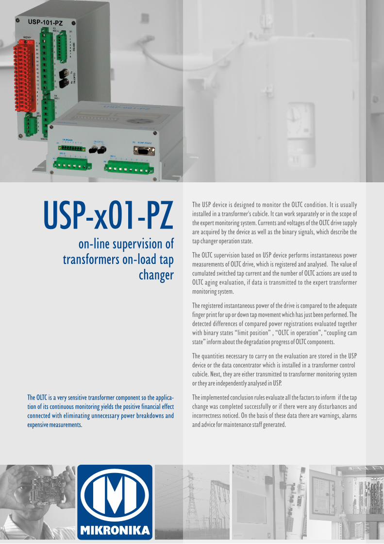
USP-x01-PZon-line supervision of
transformers on-load tap changer
The USP device is designed . It is usually installed in a transformer's cubicle. It can work separately or in the scope of the expert monitoring system. Currents and voltages of the OLTC drive supply are acquired by the device as well as the binary signals, which describe the tap changer operation state.
The OLTC supervision based on USP device performs instantaneous power measurements of OLTC drive, which is registered and analysed. The value of cumulated switched tap current and the number of OLTC actions are used to OLTC aging evaluation, if data is transmitted to the expert transformer monitoring system.
The registered instantaneous power of the drive is compared to the adequate finger print for up or down tap movement which has just been performed. The detected differences of compared power registrations evaluated together with binary states “limit position” , “OLTC in operation”, “coupling cam state” inform about the degradation progress of OLTC components.
The quantities necessary to carry on the evaluation are stored in the USP device or the data concentrator which is installed in a transformer control cubicle. Next, they are either transmitted to transformer monitoring system or they are independently analysed in USP.
The implemented conclusion rules evaluate all the factors to inform if the tap change was completed successfully or if there were any disturbances and incorrectness noticed. On the basis of these data there are warnings, alarms and advice for maintenance staff generated.
to monitor the OLTC condition
The OLTC is a very sensitive transformer component so the applica-tion of its continuous monitoring yields the positive financial effect connected with eliminating unnecessary power breakdowns and expensive measurements.
www.mikronika.pl
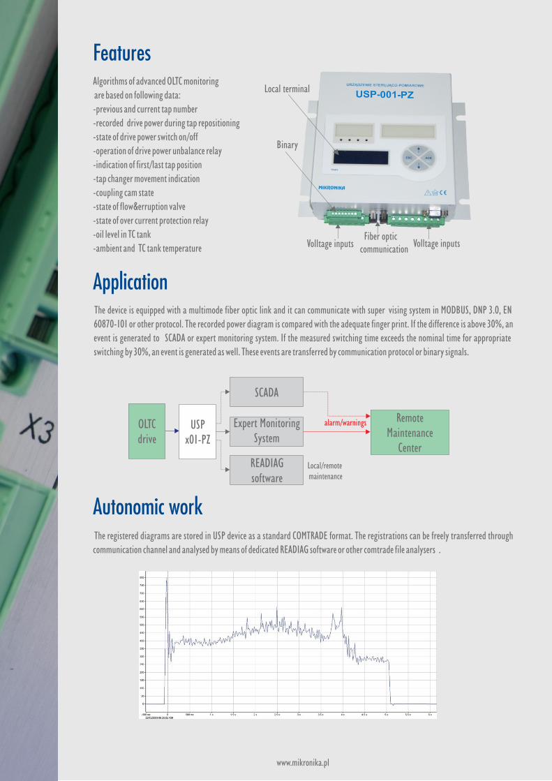
Autonomic work The registered diagrams are stored in USP device as a standard COMTRADE format. The registrations can be freely transferred through communication channel and analysed by means of dedicated READIAG software or other comtrade file analysers .
Expert Monitoring System
OLTCdrive
USPx01-PZ
READIAGsoftware
Remote Maintenance
Center
The device is equipped with a multimode fiber optic link and it can communicate with super vising system in MODBUS, DNP 3.0, EN
60870-101 or other protocol. The recorded power diagram is compared with the adequate finger print. If the difference is above 30%, an
event is generated to SCADA or expert monitoring system. If the measured switching time exceeds the nominal time for appropriate
switching by 30%, an event is generated as well. These events are transferred by communication protocol or binary signals.
FeaturesAlgorithms of advanced OLTC monitoring
are based on following data:-previous and current tap number-recorded drive power during tap repositioning-state of drive power switch on/off-operation of drive power unbalance relay-indication of first/last tap position-tap changer movement indication-coupling cam state-state of flow&erruption valve-state of over current protection relay
-oil level in TC tank
-ambient and TC tank temperature
SCADA
alarm/warnings
Local/remote maintenance
Volltage inputs Fiber optic communication
Volltage inputs
Local terminal
Binary
Application
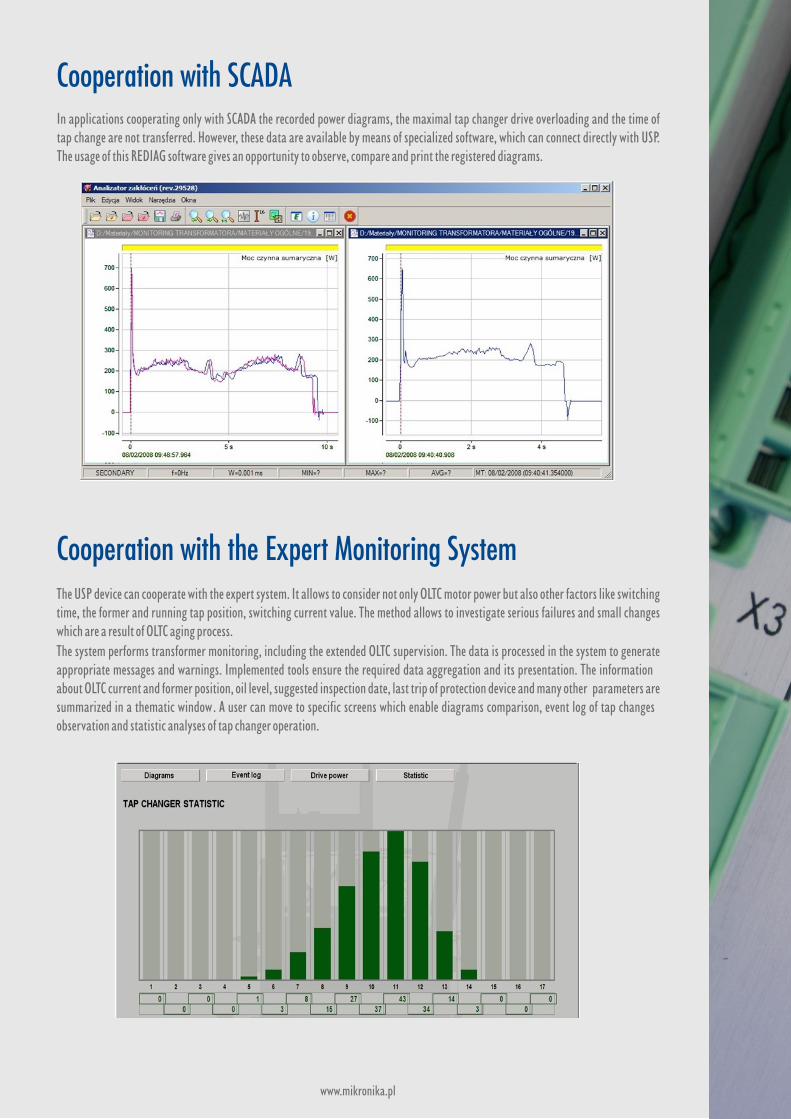
Cooperation with the Expert Monitoring SystemThe USP device can cooperate with the expert system. It allows to consider not only OLTC motor power but also other factors like switching time, the former and running tap position, switching current value. The method allows to investigate serious failures and small changes which are a result of OLTC aging process. The system performs transformer monitoring, including the extended OLTC supervision. The data is processed in the system to generate appropriate messages and warnings. Implemented tools ensure the required data aggregation and its presentation. The information about OLTC current and former position, oil level, suggested inspection date, last trip of protection device and many other parameters are summarized in a thematic window. A user can move to specific screens which enable diagrams comparison, event log of tap changes observation and statistic analyses of tap changer operation.
www.mikronika.pl
Cooperation with SCADAIn applications cooperating only with SCADA the recorded power diagrams, the maximal tap changer drive overloading and the time of tap change are not transferred. However, these data are available by means of specialized software, which can connect directly with USP. The usage of this REDIAG software gives an opportunity to observe, compare and print the registered diagrams.
Technical data
Basing on implemented conclusion rules, the system creates information and advice for dispatch staff. The concisely summarized messages are generated for local SCADA and can be transferred to Remote Maintenance Centres :
Alarms & wornings
Parametr
Output signal
USP-001-PZ
5 outputs 0,2A / 220V DC
Assembly
Serial transmission
panel mounted
3x RS-485, 1x RS-232, fiber optic
LCD monitor
Network link
internal
No
Current measurements
Modem
Voltage measurements
Power
4 inputs 0-1A AC
No
4 inputs 0-230V AC
230/220V AC/DC or 24V DC
Digital inputs
Power consumption
8 inputs 24V or 220V
6VA
USP-101-PZ
5 outputs 0,2A / 220V DC
DIN rail 35mm
2x RS-485, fiber optic
external
Ethernet FX 100MB, multimode
3 inputs 0-1A AC
GSM/GPRS/EDGE
5 inputs 0-230V AC
230/220V AC/DC or 24V DC
16 inputs 24V lub 220V
6VA
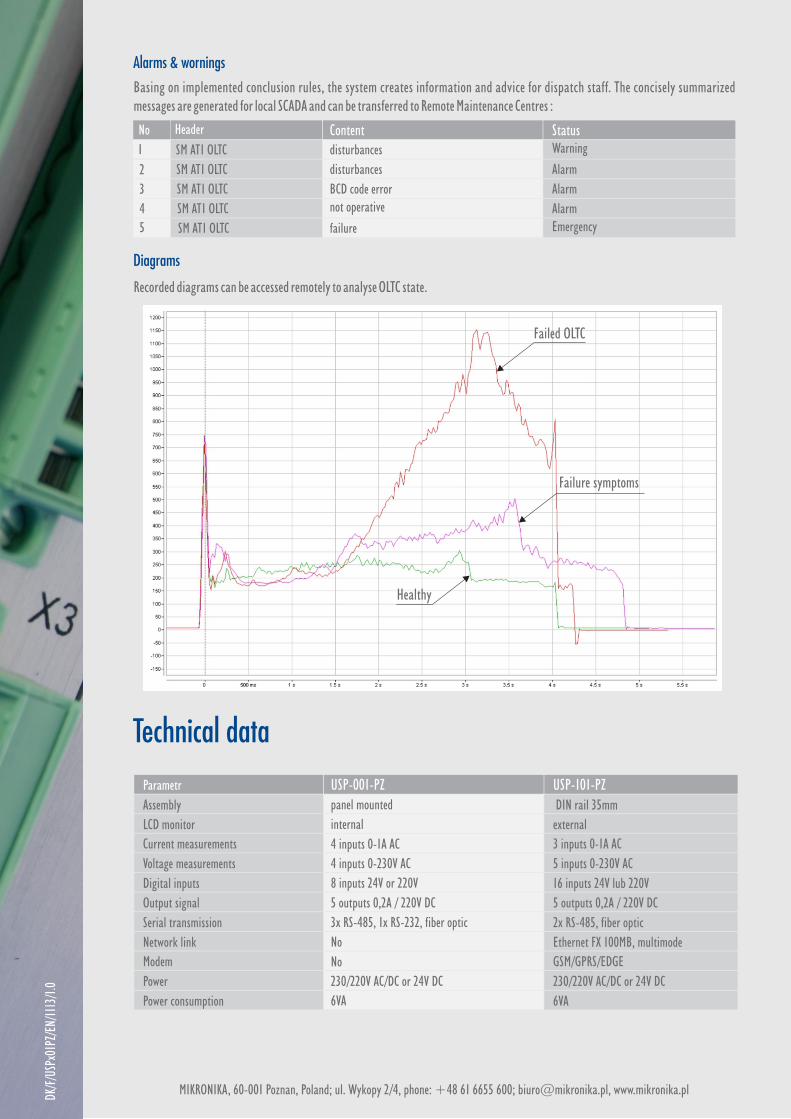
Failure symptoms
Failed OLTC
Healthy
Header ContentSM AT1 OLTC disturbances
SM AT1 OLTC disturbances
SM AT1 OLTC
SM AT1 OLTC
BCD code errornot operative
SM AT1 OLTC failure
StatusWarning
Alarm
Alarm
AlarmEmergency
No
1
2
3
4
5
DK/F
/USP
x01P
Z/EN
/111
3/1.0
MIKRONIKA, 60-001 Poznan, Poland; ul. Wykopy 2/4, phone: +48 61 6655 600; [email protected], www.mikronika.pl
Diagrams
Recorded diagrams can be accessed remotely to analyse OLTC state.